

1
Concealed Duct type (Underside intake
)
Installation Manual
High-Efficiency Filter
Model: TCB-UFM11BE (65%)
TCB-UFM21BE (65%)
TCB-UFM31BE (65%)
TCB-UFM41BE (65%)
TCB-UFH51BE (90%)
TCB-UFH61BE (90%)
TCB-UFH71BE (90%)
TCB-UFH81BE (90%)
SAFETY CAUTIONS
• Before installation work, read thoroughly this “Safety Cautions” to install the air conditioner correctly.
• This “Safety Cautions” describes the important contents concerned to the safety. Be sure to keep in mind these items.
Symbols and meanings are as described below.
WARNING
CAUTION
Indicates “User may be seriously injured (*1) if it is incorrectly used.”
Indicates “It is assumed that user may be injured (*2) or property damage (*3) may occur if it is incorrectly used.”
*1: “Serious injury” means a disease which has an after-effect or requires hospitalization or long-term going to the hospital for
treatment, such as loss of sight, burn (by high temperature or low temperature), electric shock, fracture, poisoning, etc.
*2:
“Injury” means hurt, burn, electric shock, etc. which does not require hospitalization or long-term going to the hospital for treatment.
*3: “Property damage” means enlarged damage concerned to house, household effects, domestic animal, pet, etc.
Explanation of symbols
indicates prohibition (prohibited action).
The concrete prohibited action is indicated with sentence in or near the symbol.
indicates that the forced instructed action (Act necessarily).
The concrete instructed action is indicated with sentence in or near the symbol.
indicates an item with care.
The concrete item to be cautioned is indicated with sentence in or near the symbol.
Specifications
High-Efficiency Filter
(65%) model name
Conformed air
conditioner model
name
Quantity
Dust collecting effect
Operation time (Life)
TCB-
UFM11BE
TCB-
UFM21BE
TCB-
UFM31BE
TCB-
UFM41BE
MMD-
AP0071BH
to
AP0121BH
MMD-
AP0151BH
to
AP0181BH
MMD-
AP0241BH
to
AP0301BH
MMD-
AP0361BH
to
AP0561BH
—
RAVSM561BT,
SM562BT
RAVSM801BT,
SM802BT
RAVSM1101BT to
SM1401BT,
SM1102BT to
SM1402BT
1122
65% (NBS Colorimetric method)
2500 hours
High-Efficiency Filter
(90%) model name
Conformed air
conditioner model
name
Quantity
Dust collecting effect
Operation time (Life)
TCB-
UFM51BE
TCB-
UFM61BE
TCB-
UFM71BE
TCB-
UFM81BE
MMD-
AP0071BH
to
AP0121BH
MMD-
AP0151BH
to
AP0181BH
MMD-
AP0241BH
to
AP0301BH
MMD-
AP0361BH
to
AP0561BH
—
RAVSM561BT,
SM562BT
RAVSM801BT,
SM802BT
RAVSM1101BT to
SM1401BT,
SM1102BT to
SM1402BT
1122
90% (NBS Colorimetric method)
1800 hours
WARNING
•
CAUTION
•
Keep all plastic bags away from babies
and small children as a danger of
suffocation exists.
Install the suction grille securely to the main
unit. If an incomplete installation is performed,
falling of the suction grille may causes an injury.
NOTES
• This manual should be stored together with the Owner's
manual and indoor unit installation manual.

2
Installation of High-Efficiency Filter
2
Remove the air filter, and install High-Efficiency Filter
to the inlet port.
Push the High-Efficiency Filter completely up to the end.
Check that the rear side is hanged to the hook.
Adjust the hook with plier if fixing of hook is not enough.
1
Mount the attached filter fixture plate.
3
Install the air filter
Be sure to fix the air filter with clamps in order to prevent falling.
(Clamps are attached to the indoor unit.)
NOTE
These filter cannot be reused even if it is washed.
NOTE
This filter is used for underside intake only.
In case of using MMD-AP** , install the filter kit for underside
(TCB-FK
***
BE) be fore install this filter.
Tighten the fixing screw of the blower base certainly after
attaching the filter fixture plate.
When fixing is not enough, it becomes the cause of generating,
such as a noise.
Filter fixture plate
Filter fixture plate
Blower base
Blower base
Indoor unit
SM561, SM562,
AP0071~AP0181
SM801~SM1401
SM802~SM1402
AP0241~AP0561
Air filter
High-Efficiency Filter
High-Efficiency
Filter
Hook
Loose the fixing screw of the blower base at once, insert the filter
fixture plate from width and fasten together with the blower base.
"AP0071~AP0181, SM561 and SM562" attaches one piece for
the filter fixture plate, and "AP0241~AP0561, SM801~SM1401
and SM802~SM1402" attaches two pieces.

3
UFBE-E
Setup of fan when building in the High-Efficiency Filter:
Necessary at initial installation only
Two methods are provided for setup, one is to use a wired remote controller sold separately
and the other is to exchange the short plug on the indoor microcomputer P.C. board.
Set data
0000
0001
Filter sold separately
Standard filter (At shipment)
High-Efficiency Filter (65%)
High-Efficiency Filter (90%)
* Setup can be performed only by the
wired remote controller. If setup is not
performed, air volume is decreased and
dewing occurs.
• Item code 5d
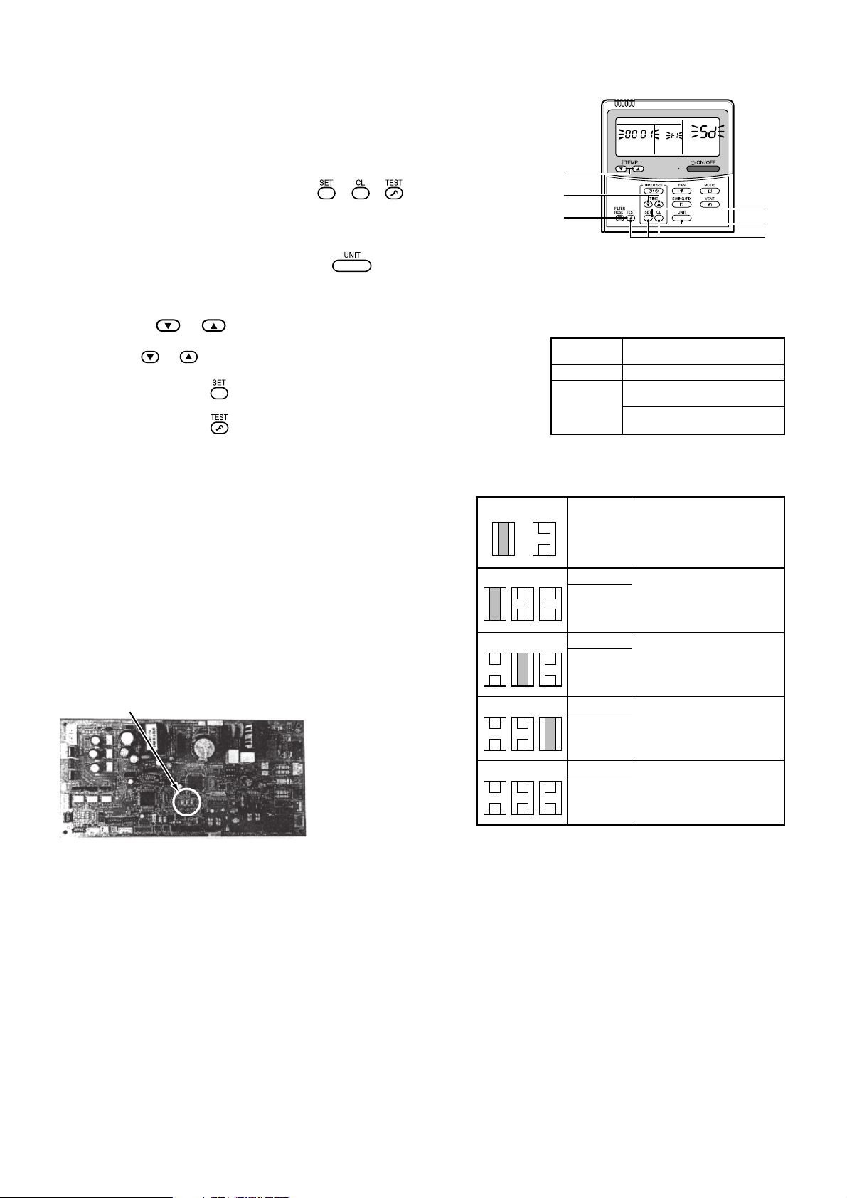
[Using a wired remote controller sold separately]
(Procedure) Perform the setup while the equipment stops.
1
Push + + buttons concurrently for 4 seconds or more.
The firstly displayed unit No. is the master indoor unit address of the group control.
In this time, the fan of the selected indoor unit only operates.
2
Every pushing button, No. of the group control units are displayed in
order.
In this time, the fan of the selected indoor unit only operates.
3
Using set temperature and buttons, specify the item code “5d”.
4
Using timer time and buttons, select from the set data.
For contents of the setup data, refer to the table at the right.
5
Push button.
(When flashing display changes to lighting display, the setup completes.)
6
Pushing button returns the state to the normal stop state.
[Exchange of short plug on indoor microcomputer P.C. board]
Short plug position (CN112, CN111, CN110 from the left)
To exchange the static pressure, there is a method other than the
abovementioned method by wired remote controller, which is to shift the
short plug on the indoor microcomputer P.C. board as shown in the
following table. Adopt this method in case of using a wireless remote
controller, etc.
* However, after exchanging once, be careful to shift the short plug to the
standard position (At shipment) in order to return to the standard setup
(follow to E
2PROM setup) though the setup for high static-pressure 1,
high static-pressure 2, or low static-pressure can be arbitrarily performed.
It is necessary to rewrite data from the wired remote controller sold
separately in the set data “0000”.
• Select with shifting of the short plug on the indoor unit
microcomputer P.C. board.
External
static
pressure
40Pa
Standard
(At shipment)
70Pa
High staticpressure 1
100Pa
High staticpressure 2
20Pa
Low staticpressure
Filter sold separately
Standard filter
(At shipment)
*1
High-Efficiency Filter 65
High-Efficiency Filter 90
*1 Resistance of High-Efficiency Filter 65 and 90is equivalent to 30Pa.
Therefore, set the resistance (external static pressure) of a duct to be connected to 40Pa.
*1
*1
Short plug position
Short
CN112 CN111 CN110
Open
CN112 CN111 CN110
CN112 CN111 CN110
CN112 CN111 CN110
3
4
6
2
1
5
CODE No.
SET DATA
UNIT No
4
UFBE-FR
Réglage du ventilateur pendant le montage du filtre à grand rendement :
Cela n’est nécessaire que lors du montage initial
Il y a deux méthodes de réglage : l’une utilise une commande à distance câblée vendue séparément
et l’autre consiste à changer la courte fiche du circuit imprimé du microordinateur intérieur.
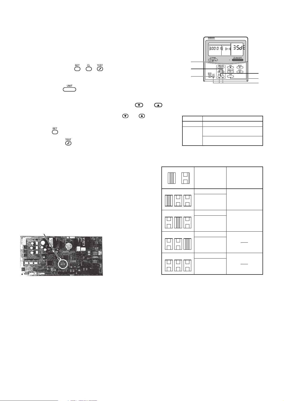
[Utilisation d’une commande à distance câblée vendue séparément]
(Procédure) Effectuez le réglage avec l’appareil à l’arrêt.
Position de la fiche courte (CN112, CN111, CN110 de gauche à droite)
1
Appuyez en même temps sur les touches + + pendant 4 secondes
ou davantage.
Le numéro d’unité qui s’affiche en premier indique l’unité intérieure principale de la
commande du groupe.
Le ventilateur de l’unité intérieure sélectionnée est alors le seul à fonctionner.
2
Chaque fois que vous appuyez sur la touche , vous affichez dans l’ordre
les numéros des unités de la commande du groupe.
Le ventilateur de l’unité intérieure sélectionnée est alors le seul à fonctionner.
3
Précisez le code de l’élément “5d” à l’aide des touches de réglage de la
température et .
4
Sélectionnez les données configurées à l’aide des touches de réglage de la
minuterie et .
Pour connaître les données configurées, consultez le tableau à droite.
5
Appuyez sur la touche . (Lorsque l’afficheur cesse de clignoter et s’éclaire
fixement, le réglage est terminé)
6
Appuyez sur la touche pour revenir à l’état d’arrêt normal.
* Vous ne pouvez effectuer le réglage
qu’avec la commande à distance câblée.
Si vous n’effectuez pas le réglage, le
volume d’air diminue et des condensats se
forment.
• Code d’élément 5d
[Changement de la courte fiche du circuit imprimé du microordinateur intérieur]
Il existe une autre méthode que celle indiquée plus haut, avec la commande à
distance câblée, pour changer la pression statique : il suffit pour cela de
changer la courte fiche du circuit imprimé du microordinateur intérieur de la
façon indiquée sur le tableau suivant. Utilisez cette méthode si vous
employez une commande à distance sans-fil, etc…
* Cependant, après avoir échangé la fiche une fois, veillez à remettre la courte
fiche dans sa position normale (départ d’usine) afin de revenir à la
configuration classique (suivez la configuration E
2PROM) même si vous
pouvez effectuer de façon arbitraire la configuration pour la pression statique
élevée 1, la pression statique élevée 2 ou la pression statique basse.
Vous devez réécrire les données de la commande à distance câblée
vendue séparément sur les données configurées “0000”.
• Effectuez la sélection en déplaçant la courte fiche du circuit
imprimé du microordinateur de l’unité intérieure.
40Pa
Standard
(départ
d’usine)
70Pa
Haute
pression
statique 1
100Pa
Haute
pression
statique 2
20Pa
Basse
pression
statique
——
——
Court Ouvert
Position du
micro-interrupteur
Données
configurées
0000
0001
Filtre vendu séparément
Filtre standard (départ d’usine)
Filtre à grand rendement (65 %)
Filtre à grand rendement (90 %)
*1
*1
Pression
statique
extérieure
*1
Filtre à grand rendement 65
Filtre à grand rendement 90
Filtre standard (départ d’usine)
Filtre vendu séparément
*1 La résistance du filtre à grand rendement 65 et 90 est égale à 30Pa.
Vous devez donc régler la résistance (pression statique extérieure) du conduit à raccorder sur 40 Pa.
CN112 CN111 CN110
CN112 CN111 CN110
CN112 CN111 CN110
CN112 CN111 CN110
3
4
6
2
1
5
CODE No.
SET DATA
UNIT No
5
UFBE-DE
Einstellen des Gebläsen bei der Installation des Hochleistungsfilters:
Nur bei der Erstinstallation erforderlich
Es bestehen zwei Möglichkeiten das Gebläse einzustellen, zum einen über die verdrahtete
Fernbedienung und zum anderen durch den Austausch des Jumpers auf der
Prozessorkarte der Raumeinheit.
[Einstellung mit der verdrahteten Fernbedienung (getrennt erhältlich)]
(Vorgehensweise) Nehmen Sie die Einstellen vor, wenn die Geräte nicht arbeiten.
Setzen Sie die Jumper CN112, CN111, CN110 (von links nach rechts gesehen).
40Pa
Standard
(Werkseinstellung)
70Pa
Hoher statischer
Druck 1
100Pa
Hoher statischer
Druck 2
20Pa
Niedriger statischer
Druck
Standardfilter
(Werkseinstellung)
*1
Hochleistungsfilter 65
Hochleistungsfilter 90
Kurzgeschlossen
Offen
Jumperposition
1
Drücken Sie gleichzeitig + + für mindestens 4 Sekunden.
Die als erste angezeigte Gerätenummer ist die Andresse der Haupteinheit der
Gruppensteuerung.
In diesem Fall arbeitet nur das Gebläse der ausgewählten Raumeinheit.
2
Jedesmal wen Sie drücken, werden die Nummern der zur Gruppe
gehörenden Einhaiten nacheinander angezeigt.
In diesem Fall arbeitet nur das Gebläse der ausgewählten Raumeinheit.
3
Geben Sie mit Hilfe der Tasten zur Temperatureinstellung und
den Code “5d” ein.
4
Wählen Sie mit Hilfe der Tasten zur Zeiteinstellung und
die Daten zur
Einstellung.
In der rechts stehenden Tabelle werden diese Daten erklärt.
5
Drücken Sie
.
(Wenn die Anzeige nicht mehr blinkt, wurde die Einstellung übernommen.)
6
Durch Drücken von
wechseln Sie zurück in den normalen Stopp-Modus.
Die Einstellung kann nur ü
*
Fernbedienung erfolgen. Wird die Einstellung
nicht durchgeführt, verringert sich die
Lüftungsleistung und es entsteht
Kondenswasser.
• Code 5d
[Austausch des Jumpers auf der Prozessorkarte der Raumeinheit]
Der statische Druck kann auch, anders als oben für die Fernbedienung
beschrieben, über die Jumper auf der Leiterplatte des Mikroprozessors der
Raumeinheit nach folgender Tabelle eingestellt werden. Verwenden Sie diese
Methode, wenn Sie nur eine drahtlose Fernbedienung etc. zur Verfügung
haben.
* Wurde die Einstellung geändert, seien Sie vorsichtig, wenn Sie sie wieder
auf die Werkseinstellung zurücksetzen wollen. Zur Rückkehr zur
Standardeinstellung folgen Sie den Anweisungen zum Setup des E
2PROM,
obwohl die Werte für den hohen statischen Druck 1 und 2 oder den
niedrigen statischen Druck beliebig festgelegt werden können.
Die Daten müssen über die separat erhältliche verdrahtete Fernbedienung
auf “0000” zurückgesetzt werden.
• Einstellung der Jumper auf der Prozessorkarte der Raumeinheit
Daten
0000
0001
Separat erhältlicher Filter
Standardfilter (Werkseinstellung)
Hochleistungsfilter (65%)
Hochleistungsfilter (90%)
*1 Der Widerstand von Hochleistungsfilter 65 und 90 entspricht jeweils 30 Pa.
*1
*1
Stellen Sie daher den Widerstand für daher den Widerstand für einen angeschlossenen Kanal (statischer Außendruck) auf 40Pa ein.
Statischer
Außendruck
Separat
erhältlicher Filter
CN112 CN111 CN110
CN112 CN111 CN110
CN112 CN111 CN110
CN112 CN111 CN110
3
4
6
2
1
5
CODE No.
SET DATA
UNIT No

CH67600302-(3)
 Loading...