

Page 1

Toshiba Personal Computer
STREAMLINE-S 10
Maintenance Manual
TOSHIBA CORPORATION
[CONFIDENTIAL]
Page 2

Copyright
© 2010 by Toshiba Corporation. All rights reserved. Under the copyright laws, this manual cannot
be reproduced in any form without the prior written permission of Toshiba. No patent liability is
assumed with respect to the use of the information contained herein.
Toshiba Personal Computer SATELLITE T210/T215/PRO T210/T215/PORTEGE T210 MAINTENANCE
MANUAL
L Maintenance Manual
First edition April, 2010
Disclaimer
The information presented in this manual has been reviewed and validated for accuracy. The
included set of instructions and descriptions are accurate for the SATELLITE T210/T215/PRO
T210/T215/PORTEGE T210 MAINTENANCE MANUALL Series at the time of this manual's
production. However, succeeding computers and manuals are subject to change without notice.
Therefore, Toshiba assumes no liability for damages incurred directly or indirectly from errors,
omissions, or discrepancies between any succeeding product and this manual.
Trademarks
IBM is a registered trademark, and OS/2 and PS/2 are trademarks of IBM Corporation.
Microsoft, MS-DOS, Windows, DirectSound and DirectMusic are registered trademarks of
Microsoft Corporation.
Intel and Pentium are registered trademarks, and SpeedStep is a trademark of Intel Corporation.
Sound Blaster is a registered trademark of Creative Technology Ltd.
Centronics is a registered trademark of Centronics Data Computer Corporation.
Photo CD is a trademark of Eastman Kodak.
All other properties are trademarks or registered trademarks of their respective holders.
ii
[CONFIDENTIAL]
SATELLITE T210/T215/PRO T210/T215/PORTEGE T210 MAINTENANCE MANUALL
Page 3
Preface
This maintenance manual describes how to perform hardware service maintenance for the Toshiba
Personal Computer SATELLITE T210/T215/PRO T210/T215/PORTEGE T210 MAINTENANCE
MANUALL, referred to as the SATELLITE T210/T215/PRO T210/T215/PORTEGE T210
MAINTENANCE MANUALL Series in this manual.
The procedures described in this manual are intended to help service technicians isolate faulty Field
Replaceable Units (FRUs) and replace them in the field.
SAFETY PRECAUTIONS
Four types of messages are used in this manual to bring important information to your attention.
Each of these messages will be italicized and identified as shown below.
DANGER: “Danger” indicates the existence of a hazard that could result in death or
serious bodily injury if the safety instruction is not observed.
WARNING: “Warning” indicates the existence of a hazard that could result in bodily
injury if the safety instruction is not observed.
CAUTION: “Caution” indicates the existence of a hazard that could result in property
damage if the safety instruction is not observed.
NOTE: “Note” contains general information that relates to your safe maintenance
service.
Improper repair of the computer may result in safety hazards. Toshiba requires service technicians
and authorized dealers or service providers to ensure the following safety precautions are adhered
to strictly.
Be sure to fasten screws securely with the right screwdriver. If a screw is not fully fastened,
it could come loose, creating a danger of a short circuit, which could cause overheating,
smoke or fire.
If you replace the battery pack or RTC battery, be sure to use only the same model battery
or an equivalent battery recommended by Toshiba. Installation of the wrong battery can
cause the battery to explode.
SATELLITE T210/T215/PRO T210/T215/PORTEGE T210 MAINTENANCE MANUALL
ONFIDENTIAL]
iii
Page 4

The manual is divided into the following parts:
Chapter 1 Hardware Overview describes the SATELLITE T210/T215/PRO
T210/T215/PORTEGE T210 MAINTENANCE MANUALL Series system
unit and each FRU.
Chapter 2 Troubleshooting Procedures explains how to diagnose and resolve FRU
problems.
Chapter 3 Test and Diagnostics describes how to perform test and diagnostic operations
for maintenance service.
Chapter 4 Replacement Procedures describes the removal and replacement of the FRUs.
Appendices The appendices describe the following:
Handling the LCD module
Board layout
Pin assignments
Keyboard scan/character codes
Key layout
Screw torque list
Reliability
Conventions
This manual uses the following formats to describe, identify, and highlight terms and operating
procedures.
Acronyms
On the first appearance and whenever necessary for clarification, acronym
s are enclosed in
parentheses following their definition. For example:
Read Only Memory (ROM)
Keys
Keys are used in the text to describe many operations. The key top symbol as it appears on the
keyboard is printed in boldface type.
Key operation
iv
[CONFIDENTIAL]
SATELLITE T210/T215/PRO T210/T215/PORTEGE T210 MAINTENANCE MANUALL
Page 5

Some operations require you to simultaneously use two or more keys. We identify such operations
by the key top symbols separated by a plus (+) sign. For example, Ctrl + Pause (Break) means you
must hold down Ctrl and at the same time press Pause (Break). If three keys are used, hold down
the first two and at the same time press the third.
User input
Text that you are instructed to type in is shown in the boldface type below:
DISKCOPY A: B:
The display
Text generated by the computer that appears on its display is presented in the typeface below:
Format complete
System transferred
SATELLITE T210/T215/PRO T210/T215/PORTEGE T210 MAINTENANCE MANUALL
ONFIDENTIAL]
v
Page 6

Table of Contents
Chapter 1
1.1
Features..............................................................................Error! Bookmark not defined.
1.2 9.5mm (2.5-inch) HDD......................................................Error! Bookmark not defined.
1.3 Power Supply.....................................................................Error! Bookmark not defined.
1.4 Batteries.............................................................................Error! Bookmark not defined.
1.4.1 Main Battery........................................................Error! Bookmark not defined.
1.4.2 Battery Charging Control....................................Error! Bookmark not defined.
1.4.3 RTC Battery........................................................Error! Bookmark not defined.
Chapter 2
2.1 Troubleshooting Introduction................................................................................................3
2.2 Troubleshooting Flowchart....................................................................................................4
2.3 Power Supply Troubleshooting .............................................................................................9
2.4 Display Troubleshooting .....................................................................................................14
2.5 Keyboard Troubleshooting..................................................................................................17
2.6 External USB Devices Troubleshooting..............................................................................19
2.7 TouchPad Troubleshooting..................................................................................................21
2.8 Speaker Troubleshootin.......................................................................................................23
2.9 Wireless LAN Troubleshooting…………………………………………………………...25
2.10 Camera troubleshooting.......................................................................................................29
2.12 4 in 1 card Troubleshooting.................................................................................................31
2.13 HDD troubleshooting process…………......................................…….…….......................33
2.14 CRT failure troubleshooting process ………
2.15 LAN troubleshooting process…………………............................................……….…….37
2.16 MIC troubleshooting process …………………................................................……….….39
2.17 3D sensor troubleshooting process........................ .............................................................41
....................................………………….….35
2.18 3G troubleshooting process………………… .......................................................……..…43
2.19 HDMI troubleshooting process……………..............................................................….….46
2.20 E-SATA troubleshooting process……............................................................................…48
vi
[CONFIDENTIAL]
SATELLITE T210/T215/PRO T210/T215/PORTEGE T210 MAINTENANCE MANUALL
Page 7

2.21 Wimax troubleshooting process ...........................................................................................50
Chapter 3
3.1 The Diagnostic Test..............................................................................................................3
3.2 Executing the Diagnostic Test.............................................................................................4
3.3 Display Configuration ........................................................................................................7
3.4 Audio sound Test.................................................................................................................8
3.5 Fan ON/OFF Test..............................................................................................................11
3.6 Main Battery Test..............................................................................................................13
3.7 FDD Test ...........................................................................................................................14
3.8 Memory Test......................................................................................................................15
3.9 Keyboard Test....................................................................................................................18
3.10 Mouse (Pad) Test...............................................................................................................20
3.11 LCD Pixels Test.................................................................................................................21
3.12 Magnetic switch Test.........................................................................................................22
3.13 LAN Test...........................................................................................................................24
3.14 RTC Test............................................................................................................................26
3.15 G-sensor Test......................................................................................................................28
3.16 HDD Test………………...………......................................................................…….......31
3.17 Read DMI Test………….……... .............................................................……..………...34
3.18 Write DMI Test....………… ..........................................................................…...……….35
3.19 Toshiba Logo Set………….…............................................................................................37
3.20 Dynabook Logo Set….…..........................................................................................….…39
3.21 TP Type R/W Test….….….…….........................................................................….…….41
3.22 EE-PROM SETTING…….….. ......................……………………….……...……….…..44
SATELLITE T210/T215/PRO T210/T215/PORTEGE T210 MAINTENANCE MANUALL
ONFIDENTIAL]
vii
Page 8

Chapter 4
4.1 General...............................................................................Error! Bookmark not defined.
Safety Precautions..............................................................Error! Bookmark not defined.
Before You Begin ..............................................................Error! Bookmark not defined.
Disassembly Procedures ....................................................Error! Bookmark not defined.
Assembly Procedures.........................................................Error! Bookmark not defined.
Tools and Equipment.........................................................Error! Bookmark not defined.
Screw Tightening Torque ..................................................Error! Bookmark not defined.
Colors of Screw Shanks.....................................................Error! Bookmark not defined.
Symbols of Screws on the Laptop Body............................Error! Bookmark not defined.
Symbol examples...............................................................Error! Bookmark not defined.
4.2 Battery................................................................................Error! Bookmark not defined.
Removing the Battery Pack ...............................................Error! Bookmark not defined.
Installing the Battery Pack.................................................Error! Bookmark not defined.
4.3 Memory..............................................................................Error! Bookmark not defined.
Removing the Optional Memory.......................................Error! Bookmark not defined.
Installing the Optional Memory.........................................Error! Bookmark not defined.
4.4 HDD...................................................................................Error! Bookmark not defined.
Removing the HDD ...........................................................Error! Bookmark not defined.
Installing the HDD.............................................................Error! Bookmark not defined.
4.5 Keyboard............................................................................Error! Bookmark not defined.
Removing the Keyboard ....................................................Error! Bookmark not defined.
Installing the Keyboard......................................................Error! Bookmark not defined.
4.6 Logic Upper Assembly......................................................Error! Bookmark not defined.
Removing the Logic Upper Assembly...............................Error! Bookmark not defined.
Installing the Logic upper assembly..................................Error! Bookmark not defined.
4.7 Power Button Board...........................................................Error! Bookmark not defined.
Removing the Power Button Board...................................Error! Bookmark not defined.
Installing the power button board......................................Error! Bookmark not defined.
4.8 Touch Pad Assembly.........................................................Error! Bookmark not defined.
Removing the Touch Pad Assembly..................................Error! Bookmark not defined.
viii
MANUALL
[CONFIDENTIAL]
SATELLITE T210/T215/PRO T210/T215/PORTEGE T210 MAINTENANCE
Page 9

Installing the Touch Pad Assembly...................................Error! Bookmark not defined.
4.9 WLAN Card.......................................................................Error! Bookmark not defined.
Removing the WLAN Card...............................................Error! Bookmark not defined.
Installing the WLAN Card.................................................Error! Bookmark not defined.
4.10 WWAN Card.....................................................................Error! Bookmark not defined.
Removing the WWAN Card..............................................Error! Bookmark not defined.
Installing the WWAN Card ...............................................Error! Bookmark not defined.
4.11 IO Board ............................................................................Error! Bookmark not defined.
Removing the IO Board.....................................................Error! Bookmark not defined.
Installing the IO Board ......................................................Error! Bookmark not defined.
4.12 Minicard Brackets..............................................................Error! Bookmark not defined.
Removing the Minicard Brackets......................................Error! Bookmark not defined.
Installing the Minicard Brackets........................................Error! Bookmark not defined.
4.13 HDD Board........................................................................Error! Bookmark not defined.
Removing the HDD Board ................................................Error! Bookmark not defined.
Installing the HDD Board..................................................Error! Bookmark not defined.
4.14 Bluetooth Module..............................................................Error! Bookmark not defined.
Removing the Bluetooth Module.......................................Error! Bookmark not defined.
Installing the Bluetooth Module........................................Error! Bookmark not defined.
4.15 RGB Board ........................................................................Error! Bookmark not defined.
Removing the RGB Board.................................................Error! Bookmark not defined.
Installing the RGB Board ..................................................Error! Bookmark not defined.
4.16 Display Assembly..............................................................Error! Bookmark not defined.
Removing the Display Assembly ......................................Error! Bookmark not defined.
Installing the Display Assembly........................................Error! Bookmark not defined.
4.17 Motherboard ......................................................................Error! Bookmark not defined.
Removing the Motherboard...............................................Error! Bookmark not defined.
Installing the Motherboard ................................................Error! Bookmark not defined.
4.18 LED Cable and LED Board...............................................Error! Bookmark not defined.
Removing the LED Cable and Board................................Error! Bookmark not defined.
Installing the LED Cable and LED Board.........................Error! Bookmark not defined.
4.19 Speakers.............................................................................Error! Bookmark not defined.
SATELLITE T210/T215/PRO T210/T215/PORTEGE T210 MAINTENANCE MANUALL
ONFIDENTIAL]
ix
Page 10

Removing the Speakers......................................................Error! Bookmark not defined.
Installing the Speakers.......................................................Error! Bookmark not defined.
4.20 Thermal Module ................................................................Error! Bookmark not defined.
Removing the Thermal Module.........................................Error! Bookmark not defined.
Installing the Thermal Module...........................................Error! Bookmark not defined.
4.21 LCD Bezel .........................................................................Error! Bookmark not defined.
Removing the LCD Bezel..................................................Error! Bookmark not defined.
Installing the LCD Bezel ...................................................Error! Bookmark not defined.
4.22 LCD Module......................................................................Error! Bookmark not defined.
Removing the LCD Module...............................................Error! Bookmark not defined.
Installing the LCD Module................................................Error! Bookmark not defined.
Removing the Camera Module..........................................Error! Bookmark not defined.
Installing the Camera Module............................................Error! Bookmark not defined.
4.23 WLAN Antennas ...............................................................Error! Bookmark not defined.
Removing the WLAN Antennas........................................Error! Bookmark not defined.
Installing the WLAN Antennas .........................................Error! Bookmark not defined.
Figures
Figure 1-1A ID Parts Description Placement Part A .................Error! Bookmark not defined.
Figure 1-2 SATA HDD ...........................................................Error! Bookmark not defined.
Figure 2-1 Troubleshooting flowchart (1/2) .............................................................................5
Figure 2-1 Troubleshooting flowchart (2/2) .............................................................................6
Figure 2-2 Power Supply Troubleshooting Process ..................................................................9
Figure 2-3 Display troubleshooting process............................................................................14
Figure 2-4 Keyboard troubleshooting process.........................................................................17
Figure 2-5 External USB device troubleshooting process.......................................................19
Figure 2-6 TouchPad troubleshooting process........................................................................21
Figure 2-7 Speaker troubleshooting process............................................................................23
Figure 2-8 Wireless LAN troubleshooting process..................................................................25
Figure 2-9 Camera troubleshooting process.............................................................................27
Figure 2-10 Bluetooth troubleshooting process.........................................................................29
x
[CONFIDENTIAL]
SATELLITE T210/T215/PRO T210/T215/PORTEGE T210 MAINTENANCE MANUALL
Page 11

Figure 2-11 2 in 1 card troubleshooting process .......................................................................31
Figure 2-12 HDD troubleshooting process................................................................................33
Figure 2-13 CRT troubleshooting process ................................................................................35
Figure 2-14 LAN troubleshooting process ...............................................................................37
Figure 2-15 MIC troubleshooting process.................................................................................39
Figure 2-16 3D sensor troubleshooting process.........................................................................41
Figure 2-17 3G troubleshooting process ....................................................................................43
Figure 4.1 Removing the battery pack......................................Error! Bookmark not defined.
Figure 4.2 Removing the bottom door......................................Error! Bookmark not defined.
Figure 4.3 Removing the right hand RAM from the laptop.....Error! Bookmark not defined.
Figure 4.4 Removing left hand RAM from the laptop..............Error! Bookmark not defined.
Figure 4.5 Removing the bottom door.......................................Error! Bookmark not defined.
Figure 4.6 Removing the HDD pack from the HDD bay..........Error! Bookmark not defined.
Figure 4.7 Removing the HDD foil...........................................Error! Bookmark not defined.
Figure 4.8 Removing the keyboard ...........................................Error! Bookmark not defined.
Figure 4.9 Releasing the keyboard hooks..................................Error! Bookmark not defined.
Figure 4.10 Prying up the keyboard ............................................Error! Bookmark not defined.
Figure 4.11 Removing the keyboard ...........................................Error! Bookmark not defined.
Figure 4.12 Removing eight screws from the bottom of the laptopError! Bookmark not defined.
Figure 4.13 Disconnecting the logic upper assembly cables.......Error! Bookmark not defined.
Figure 4.14 Prying up the logic upper assembly.........................Error! Bookmark not defined.
Figure 4.15 Removing the power button board...........................Error! Bookmark not defined.
Figure 4.16 Removing the touch pad assembly screws...............Error! Bookmark not defined.
Figure 4.17 Removing the touch pad assembly...........................Error! Bookmark not defined.
Figure 4.18 Removing the touch pad button board from the touch pad bracketError! Bookmark not
defined.
Figure 4.19 Removing the WLAN card ......................................Error! Bookmark not defined.
Figure 4.20 Removing the WWAN card.....................................Error! Bookmark not defined.
Figure 4.21 Removing the IO Board...........................................Error! Bookmark not defined.
Figure 4.22 Sliding out the IO Board..........................................Error! Bookmark not defined.
Figure 4.23 Removing the minicard bracket...............................Error! Bookmark not defined.
Figure 4.24 Removing the minicard bracket 2............................Error! Bookmark not defined.
SATELLITE T210/T215/PRO T210/T215/PORTEGE T210 MAINTENANCE MANUALL
ONFIDENTIAL]
xi
Page 12

Figure 4.25 Removing the HDD board........................................Error! Bookmark not defined.
Figure 4.26 Removing the Bluetooth module..............................Error! Bookmark not defined.
Figure 4.27 Removing the RGB board........................................Error! Bookmark not defined.
Figure 4.28 Removing the display assembly...............................Error! Bookmark not defined.
Figure 4.29 Removing motherboard from logic lower assemblyError! Bookmark not defined.
Figure 4.30 Installing the motherboard .......................................Error! Bookmark not defined.
Figure 4.31 Disconnecting the LED cable...................................Error! Bookmark not defined.
Figure 4.32 Removing the LED board.........................................Error! Bookmark not defined.
Figure 4.33 Removing the speakers.............................................Error! Bookmark not defined.
Figure 4.34 Disconnecting the thermal fan cable from the motherboardError! Bookmark not
defined.
Figure 4.35 Removing the four screws from the thermal moduleError! Bookmark not defined.
Figure 4.36 Applying Shinetsu 7762 grease on the thermal moduleError! Bookmark not defined.
Figure 4.37 Securing the thermal module to the motherboard with four screwsError! Bookmark not
defined.
Figure 4.38 Connecting the thermal fan cable to the motherboardError! Bookmark not defined.
Figure 4.39 Prying up the LCD bezel..........................................Error! Bookmark not defined.
Figure 4.40 Removing the LCD bezel.........................................Error! Bookmark not defined.
Figure 4.41 Removing the LCD panel.........................................Error! Bookmark not defined.
Figure 4.42 Disconnecting the camera cable...............................Error! Bookmark not defined.
Figure 4.43 Removing the LCD hinges.......................................Error! Bookmark not defined.
Figure 4.44 Removing the LVDS cable.......................................Error! Bookmark not defined.
Figure 4.45 Prying up the camera................................................Error! Bookmark not defined.
Figure 4.46 Removing the WLAN antennas ...............................Error! Bookmark not defined.
Figure 4.47 Installing the WLAN antennas.................................Error! Bookmark not defined.
Appendices
Appendix A Handling the LCD Module................................................................................... A-1
Appendix B Board Layout.........................................................................................................B-1
Appendix C Pin Assignments....................................................................................................C-1
Appendix D Keyboard Scan/Character Codes.......................................................................... D-1
Appendix E Key Layout............................................................................................................E-1
xii
MANUALL
[CONFIDENTIAL]
SATELLITE T210/T215/PRO T210/T215/PORTEGE T210 MAINTENANCE
Page 13

Appendix F Series Screw Torque List....................................................................................... F-1
Appendix G Reliability............................................................................................................. G-1
SATELLITE T210/T215/PRO T210/T215/PORTEGE T210 MAINTENANCE MANUALL
ONFIDENTIAL]
xiii
Page 14

Chapter 1
Hardware Overview
Page 15

1 Hardware Overview
Chapter 1 Contents
1.1 Features .................................................................................................................. 1-1
1.2 9.5mm (2.5-inch) HDD........................................................................................1-10
1.3 Power Supply ....................................................................................................... 1-11
1.4 Batteries................................................................................................................ 1-13
1.4.1 Main Battery......................................................................................... 1-13
1.4.2 Battery Charging Control ..................................................................... 1-13
1.4.3 RTC Battery..........................................................................................1-14
Satellite T210/T215/Pro T210/T215/PORTEGE T210 Maintenance Manual 1-ii
Page 16

1 Hardware Overview
Figures
Figure 1-1A ID Parts Description Placement Part A..........................................................1-6
Figure 1-2 SATA HDD ................................................................................................. 1-10
Tables
Table 1-1 HDD Specifications.....................................................................................1-10
Table 1-2 Quick/Normal Charging Time..................................................................... 1-13
Satellite T210/T215/Pro T210/T215/PORTEGE T210 Maintenance Manual 1-iii
Page 17

Page 18

Error! No text of specified style in document. Error! No text of specified style in document. 1
Hardware Overview
1.1 Features
The Toshiba Satellite T210/T215/Pro T210/T215/PORTEGE T210 series portable personal
computer is based on a Dual Core/Quad Core Processor, providing high-speed processing
capabilities and advanced features. The computer employs a lithium ion battery that allows it to
be battery-operated for a long period of time. The display uses a 16.0-inch WXGA LCD panel.
The PGA socket supports BTO for the CPU so that the system can be designed to suit the
customer’s needs.
The computer has the following features:
Processor (BTO)
The computer is equipped with one of the following Intel
®
processors.
Intel® Arrandale processor (18W SFF)
Supports Intel® Turbo Boost Technology, Intel® Hyper Threading and Intel® Stable
Image Platform Program
Memory (BTO)
The computer has two SODIMM slots that come standard with 1GB/2GB/4GB, BTO for
various memory requirements. It can incorporate up to 8 GB of main memory. It supports
dual channel DDR3 at 1066MHz/1333MHZ.
Battery Pack
The computer is powered by one 6-cell rechargeable and removable lithium ion battery
pack.
RTC Battery
The internal RTC battery backs up the Real Time Clock and calendar.
Hard Disk Drive (HDD) (BTO)
The computer accommodates 9.5 mm or 12.5 mm HDD sizes with following storage
capacities:
160/250/320/500/640 GB (9.5 mm thick) SATA (5,400rpm)
250/320/500 GB (9.5 mm thick) SATA (7,200rpm)
Satellite T210/T215/Pro T210/T215/PORTEGE T210 Maintenance Manual 1-1
Page 19

1 Hardware Overview Error! No text of specified style in document. Error! No text of specified
style in document.
Display (BTO)
The computer display features one of the following LCD panels:
11.6”W HD CSV LED (16:9, 1366x768)
Graphics (BTO)
Intel® Arrandale with Ibex Peak HM55 for integrated graphics.
Toshiba Value Added Package support featuring VideoStream Playback for external
monitor under simultaneous display mode.
Dual external monitor support.
HDMI V1.3 support (without CEC)
Keyboard (BTO)
The computer is equipped with a Toshiba NB200 keyboard with 86 keys. It is a Win7
compliant keyboard, featuring a Windows key and other application keys.
Pointing Device
The integrated Wide Touch Pad and two control buttons in the palm rest allow control of
the on-screen pointer and support functions such as multi-touch touchpad gestures and
window scrolling.
External Monitor Port (BTO)
The computer features an external monitor port with support for VideoStream Playback and
simultaneous display mode.
Universal Serial Bus (USB) Ports
The computer has two USB 2.0 ports. It is supported to daisy-chain a maximum of 127
USB devices. The serial data transfer rate is 480 Mbps or 12 Mbps and 1.5 Mbps. These
ports support PnP installation and hot plugging.
eSATA/USB Combo Port
The external eSATA/USB combo port executes high-speed data transfers to external
devices and now supports shielded cable lengths of up to 2 meters outside the computer.
The port also complies with the USB 2.0 standard and supports the sleep and charge
Satellite T210/T215/Pro T210/T215/PORTEGE T210 Maintenance Manual 1-2
Page 20

Error! No text of specified style in document. Error! No text of specified style in document. 1
Hardware Overview
function.
Satellite T210/T215/Pro T210/T215/PORTEGE T210 Maintenance Manual 1-3
Page 21

1 Hardware Overview Error! No text of specified style in document. Error! No text of specified
style in document.
Bridge Media Slot
This slot allows you to insert SD, MiniSD/ MicroSD (through adapter), Memory
Stick/Memory Stick Duo (through adaptor), Memory Stick Pro/Memory Stick Duo (through
adaptor), xD and MMC memory cards. It supports High-speed SD, SDHC and SD-IO. An
I/O port heel cover is needed. This model does not support CF or Smart Media cards.
Sound system
The integrated sound system is composed of two internal speakers, an internal microphone
(equipped with echo cancellation) as well as standard MIC-IN and S/PDIF-OUT ports.
Internal Camera (BTO)
Camera supports 1.3M pixels without Auto Macro and comes with a blue LED indicator.
(The internal camera is BTO with the internal microphone). The camera is not a rotation
type.
HDMI Out Port (BTO)
HDMI 1.3 out port can connect with Type A connector HDMI cable. One HDMI cable can
send and receive SD and HD video/audio and control signals (no CEC support).
Headphones/S/PDIF/Line out Jack
This jack connects digital speakers or stereo headphones (16 ohm minimum). When
connected to digital speakers or headphones, the internal speaker is automatically disabled.
This jack can also be used as a S/PDIF port and can enable connection of optical-digital
correspondence devices.
Microphone/ Line-in Jack
A 3.5mm mini microphone jack enables connection of a three-conductor microphone for
monaural input and also enables the connection of a stereo device for audio input.
LAN (BTO)
The computer has built-in support for Gigabit Ethernet LAN (1000 megabits per second,
1000BASE-T) and 10M/100M Ethernet LAN (10/100 megabits per second, 10/100BASET). It employs a Realtek 8105E for 10M/100Mbit LAN.
Satellite T210/T215/Pro T210/T215/PORTEGE T210 Maintenance Manual 1-4
Page 22

Error! No text of specified style in document. Error! No text of specified style in document. 1
Hardware Overview
Wireless LAN (BTO)
Some computers in this series are equipped with a Wireless LAN card. This WLAN module
may come in with the following types (depending on the model):
Realtek 802.11bgn 8191SE
Atheros 802.11b/g HB95
Broadcom 802.11bgn/bg 4313 (WLAN/BT) w/ Bluetooth V3.0+HS
3G WWAN (BTO)
The computer has built-in support for an optional 3G enabled WWAN card, allowing the
user to enjoy mobile broadband rates.
Bluetooth (BTO)
Some computers in this series offer Bluetooth wireless communication functionality which
eliminates the need for cables between electronic devices such as computers and printers.
When implemented, Bluetooth provides a fast, reliable and secure means to achieve
wireless communication in a small space. This module is Version 2.1 + EDR (Antenna on
Module type).
Sound system (BTO)
The integrated sound system uses the Realtek ALC259 audio codec and provides support
for the computer’s two internal speakers and microphone, also allowing an external
microphone and headphones to be connected via the appropriate jacks.
Satellite T210/T215/Pro T210/T215/PORTEGE T210 Maintenance Manual 1-5
Page 23
1 Hardware Overview Error! No text of specified style in document. Error! No text of specified
style in document.
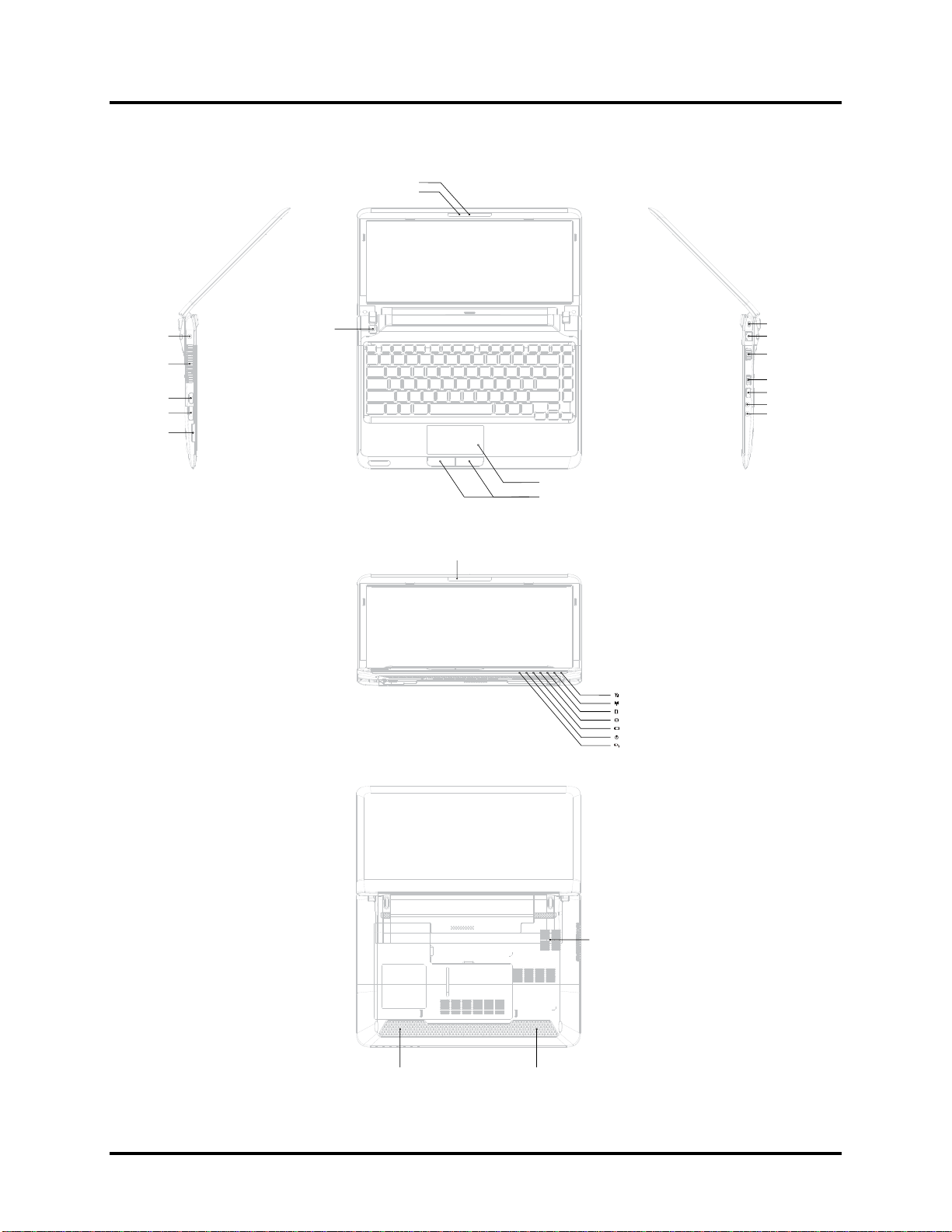
Figure 1-1A shows the computer and its system unit configuration.
Camera
Camera LED Lens Blue
:
DC-IN
Thermal Van Holes
HDMI
e-SATA
Card Reader
Power BTN
Microphone
Touch Pad
TP BTN
WiMax/3G: Blue
Wireless / RF status: Amber
Bridge Media: White
HDD/ODD/e-SATA: White
Main Battery: /Amber/Amber<Blink>White
Power: /Amber<Blink>White
DC-IN:White
Kensington Lock
RJ-45
VGA
USB
USB
Microphone (Chrome ring)
Headphone (Chrome ring)
Battery
Thermal Van Holes
Bottom Door
Speaker
Speaker
Figure 1-1A ID Parts Description Placement Part A
Satellite T210/T215/Pro T210/T215/PORTEGE T210 Maintenance Manual 1-6
Page 24
Error! No text of specified style in document. Error! No text of specified style in document. 1
Hardware Overview
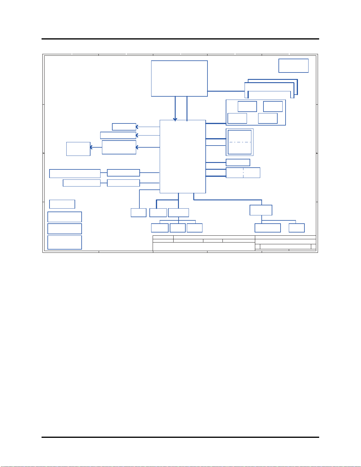
Clock Generator
SLG8SP587VTR
page 11,10
Block Diagrams
E
SPK CONN
E
page 12
page 30
245Monday, February 08, 2010
of
A
B
C
D
Compal Confidential
Model Name :NDU00/NDU10
File Name : LA-6031P
1
page 27
page 28page 28
LVDS-A
RGB
DDP-C
PCIe 1x
1.5V 2.5GHz(250MB/s)
PCIe 1x
1.5V 2.5GHz(250MB/s)
SPI
LCD Conn.
2
CRT (Sub-board)
HDMI Conn.
page 14
3 3
Cardreader conn.
HDMI Level Shifter
page 27
page 12
page 13
page 14
RTL8105E 10/100M
PCIe port 1
CardRead
er OZ600FJ1LN
PCIe port 5
Power/B
page 33
RTC CKT.
4
DC/DC Interface CKT.
SPI ROM
page 15
page 34
page 15
Debug Por t
Touch Pad
Power Circuit DC/DC
page 37~43
A
B
Mobile
Arrandale CPU
BGA 1288pins
page 5,6,7,8,9
FDI X8
DMI
2.5GHz2.7GHz
Intel Ibex Peak
BGA1071
FC
page 15~23
3.3V 33 MHz
LPC BUS
ENE KB926 D3
page 32
page 33
Security Classification
Issued Dat e
THIS SHEET OF ENGINEERING DRAWING IS THE PROPRIETARY PROPERTY OF COMPAL ELECTRONICS, INC. AND CONTAINS CONFIDENTIAL
AND TRADE SECRET INFORMATION. THIS SHEET MAY NOT BE TRANSFERED FROM THE CUSTODY OF THE COMPETENT DIVISION OF R&D
DEPARTMENT EXCEPT AS AUTHORIZED BY COMPAL ELECTRONICS, INC. NEITHER THIS SHEET NOR THE INFORMATION IT CONTAINS
MAY BE USED BY OR DISCLOSED TO ANY THIRD PARTY WITHOUT PRIOR WRITTEN CONSENT OF COMPAL ELECTRONICS, IN C.
page 31
EC ROM
Int.KBD
page 25
2009/01/23 2010/01/23
C
X4
HD Audio
page 32
Compal Secret Data
Memory BUS(DDRIII)
Dual Channel
1.5V DDRIII 800/1066 MT/s
3G
USB
3.3V/1.5V 24MHz
USB port 1 2
PCIeMini Card
WiMax
PCIeMini Card
WLAN
A HDD0
S TA
eSATARJ45+Trans former (Sub-board)
USB
5V 480MHz
5V 480MHz
PCIe 1x
1.5V 2.5GHz(250MB/s)
SATA port 1
5V 3GHz(300MB/s)
SATA port 5
5V 3GHz(300MB/s)
USB port 3
5V 480MHz
Deciphered Date
page 26
page 24
D
200pin DDRIII-SO-DIMM X2
BANK
0, 1, 2, 3
USB/B
USB port 0,1
page 30
USB port 13
page 26
PCIe port 2
page 26
page 24
USB
USB port 3
BT conn
USB port 5
page 25
Int. Camera
USB port 11
page 12
page 24
HDA Codec
ALC259
page 29
Audio sub-board
page 30
Compal Electronics, Inc.
Title
Size Docu ment Number Re v
NDU00_LA-6031P M/B
Date: Sheet
1
2
4
0.3
Satellite T210/T215/Pro T210/T215/PORTEGE T210 Maintenance Manual 1-7
Page 25

1 Hardware Overview Error! No text of specified style in document. Error! No text of specified
style in document.
The system unit of the computer consists of the following components:
Processor (BTO)
The computer is equipped with one of the following Intel® processors:
Intel® Arrandale processor (18W SFF)
Supports Intel® Turbo Boost Technology, Intel® Hyper Threading and Intel® Stable
Image Platform Program
Memory (BTO)
The computer has two SODIMM slots that come standard with 1GB/2GB/4GB, BTO for
various memory requirements. It can incorporate up to 8 GB of main memory. It supports
DDR3 at 1066MHZ/1333MHZ (Works at 800MHZ with Arrandale processor).
BIOS ROM (EEPROM)
The system BIOS and Keyboard BIOS share one single 2048KB flash ROM which is
ACPI-compliant. The flash utility can be used to program both system and keyboard BIOS
at the same time.
System Controllers
Advanced Power Management 1.2 support
ACPI2.0 b and PC2001 compliant
Support SMBus specification V2.0
Hot keys for system control
Audio volume output control
External LED control
Battery scope report and control
Sticky key support
Power switch control
Two host interface channels support
Supports three independent devices
Internal Keyboard country selection
Wireless LAN on/off button
Satellite T210/T215/Pro T210/T215/PORTEGE T210 Maintenance Manual 1-8
Page 26

Error! No text of specified style in document. Error! No text of specified style in document. 1
Hardware Overview
Graphics Controller
Intel® Arrandale with Ibex Peak HM55 for integrated graphics.
Toshiba Value Added Package support featuring VideoStream Playback for external
monitor under simultaneous display mode.
Dual external monitor support.
HDMI V1.3 support (without CEC)
Audio Controller
Realtek Azalia ALC259
One Audio-in port: Mic.-in/Line-in
One Audio-out port: Headphone-out / Line-out / S / PDIF-out
Internal Microphone (with Internal Camera, MIC with echo cancellation)
Volume control: Digital control, feather touch button, no mute function
Microsoft inbox audio driver support
Software EQ support
Synchronize to change video and audio output to HDMI/DP
MAXX audio support by SW solution (BTO by image)
Wireless LAN Controller
Realtek 802.11bgn 8191SE
Atheros 802.11b/g HB95
Broadcom 802.11bgn/bg 4313 (WLAN/BT) w/ Bluetooth V3.0+HS
Satellite T210/T215/Pro T210/T215/PORTEGE T210 Maintenance Manual 1-9
Page 27
1 Hardware Overview Error! No text of specified style in document. Error! No text of specified
style in document.
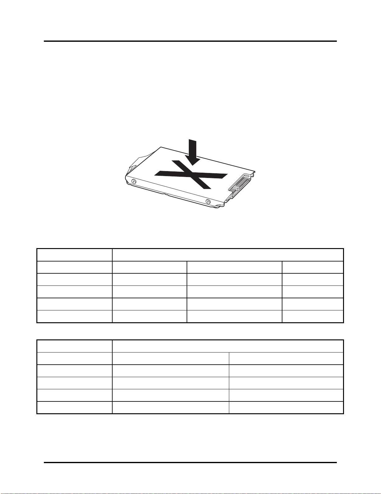
1.2 9.5mm (2.5-inch) HDD
The computer contains an extremely low-profile and lightweight, high-performance HDD. The
9.5 mm HDD incorporates HDD Protection, and NCQ and 3D sensor support. The HDD
interface conforms to Serial ATA. Storage capacities supported are 160, 250, 320, 500 and
640GB.
The HDD is shown in Figure 1-2 and some of its specifications are listed in Table 1-1.
Figure 1-2 SATA HDD
Table 1-1 HDD Specifications
Item
Capacity (GB)
Rotational Speed (RPM)
Height
User Data Sectors
Bytes / Sector 512 512 512
160G 250G 320 GB
5400 RPM 5400 or 7200 RPM 5400 or 7200 RPM
9.5mm, 2.5” 9.5mm, 2.5” 9.5mm, 2.5”
312,581,808 488,397,168 625,142,448
Specifications
Item
Capacity (GB)
Rotational Speed (RPM)
Height
User Data Sectors
500G 640 GB
5400 or 7200 RPM 5400 RPM
9.5mm, 2.5” 9.5mm, 2.5”
976,773,168 1,250,263,728
Specifications
Bytes / Sector 512 512
Satellite T210/T215/Pro T210/T215/PORTEGE T210 Maintenance Manual 1-10
Page 28

Error! No text of specified style in document. Error! No text of specified style in document. 1
Hardware Overview
1.3 Power Supply
The power supply unit provides constant voltage (19V) for the system board and performs the
following functions:
1. Power input monitor
Checks whether the AC adapter (DC power supply) is connected to the computer.
Checks whether the battery pack is connected to the computer.
Monitors the DC power supply input voltage (AC Adapter output voltage).
2. Power supply's internal control
Turns on and off the battery pack charging power supply.
Issues a charging current instruction to the PWM control IC of the battery pack charging
power supply.
Controls the supply of DC power supply input (AC Adapter output) to the power supply
unit.
Controls the supply of power to the system block (load/logic circuit side).
Controls forced shutdown if the power supply malfunctions.
3. Logic circuit control
Instructs the gate array to enable/disable tuning the power on.
Controls power-on/off operation.
4. Status display
Turns on the Power LED (in White).
Battery indicator (in White or Amber).
DC-IN indicator (in White color)
5. External interface
Performs communication through the I2C bus (via the internal EC/KBC).
Transfers the power supply operation mode.
Satellite T210/T215/Pro T210/T215/PORTEGE T210 Maintenance Manual 1-11
Page 29

1 Hardware Overview Error! No text of specified style in document. Error! No text of specified
style in document.
6. Output monitor
Monitors the voltage output to the system block (load/logic circuit side).
Monitors the voltage, over-voltage, input/output current of the battery pack.
Monitors the internal temperature of the battery pack.
Monitors the supply voltage from the AC adapter.
Satellite T210/T215/Pro T210/T215/PORTEGE T210 Maintenance Manual 1-12
Page 30
Error! No text of specified style in document. Error! No text of specified style in document. 1
Hardware Overview
1.4 Batteries
The computer has the following two types of batteries:
Main Battery Pack
Real Time Clock (RTC) Battery
1.4.1 Main Battery
The main battery pack serves as the computer's main power source when the AC adapter is not
attached. The main battery maintains the state of the computer when the AC adapter is detached.
1.4.2 Battery Charging Control
Battery charging is controlled by EC KB926. When the AC adapter and battery pack are attached
to the computer, the EC KB926 controls the charge on/off state and detects a full charge.
Battery Charge
When the AC adapter is attached, the battery is charged by off-state charge when the system
is powered off or by on-state charge when it is powered on.
Table 1-2 Quick/Normal Charging Time
State Charge Time
Off-State Charge 6 Cell Approximately 4 hours
On-State Charge 6 Cell Approximately 4 hours
Satellite T210/T215/Pro T210/T215/PORTEGE T210 Maintenance Manual 1-13
Page 31

1 Hardware Overview Error! No text of specified style in document. Error! No text of specified
style in document.
NOTE: The time required for normal charge depends on the power consumption by the
system. Using a fluorescent lamp and frequently accessing the disk consumes more power and
lengthens the charge time.
The following can stop battery charge:
1. The battery becomes fully charged.
2. The AC adapter or battery pack is removed.
3. The battery or AC adapter voltage is abnormal.
Detection of full charge
A full charge is detected only when the battery is being charged by quick or normal charge.
A full charge is detected when either of the following conditions is met:
1. The current in the battery charging circuit drops below the predetermined value.
2. The charging time exceeds the fixed limit.
1.4.3 RTC Battery
The RTC battery provides power to maintain the current date, time and other system information
in memory while the computer is turned off.
Satellite T210/T215/Pro T210/T215/PORTEGE T210 Maintenance Manual 1-14
Page 32

Chapter 2
Troubleshooting Procedures
Page 33

Page 34

2 Troubleshooting Procedures
Chapter 2 Contents
2.1 Troubleshooting Introduction......................................................................................3
2.2 Troubleshooting Flowchart..........................................................................................4
2.3 Power Supply Troubleshooting ...................................................................................9
2.4 Display Troubleshooting ...........................................................................................14
2.5 Keyboard Troubleshooting........................................................................................17
2.6 External USB Devices Troubleshooting............................................................................19
2.7 Touch pad Troubleshooting.............................................................................................21
2.8 Speaker Troubleshooting.................................................................................................23
2.9 Wireless LAN Troubleshooting.....................................................................................25
2.10 Camera Troubleshooting..............................................................................................27
2.11 Bluetooth Troubleshooting........................................................................................29
2.12 4in1 card Troubleshooting...........................................................................................31
2.13 HDD Troubleshooting ................................................................................................33
2.14 CRT Troubleshooting ..................................................................................................35
2.15 LAN Troubleshooting..................................................................................................37
2.18 3G Troubleshooting.......................................................................................................43
2.19 HDMI Troubleshooting.............................................................................................46
2.20 E-SATA Troubleshooting..........................................................................................48
2.21 Wimax Troubleshooting ................................................................................................50
Satellite T210/T215 Series Maintenance Manual 1
Page 35

2 Troubleshooting Procedures
Figures
Figure 2-1 Troubleshooting flowchart (1/2)……………………………………………….5
Figure 2-1 Troubleshooting flowchart (2/2)……………………………………………….6
Figure 2-2 Power Supply Troubleshooting Process……………………………………….9
Figure 2-3 Display troubleshooting process……………………………………………...14
Figure 2-4 Keyboard troubleshooting process……………………………………………17
Figure 2-5 External USB device troubleshooting process………………………………..19
Figure 2-6 TouchPad troubleshooting process…………………………………………...21
Figure 2-7 Speaker troubleshooting process……………………………………………...23
Figure 2-8 Wireless LAN troubleshooting process...........................................................25
Figure 2-9 Camera troubleshooting process .....................................................................27
Figure 2-10 Bluetooth troubleshooting process…..……………………………….……….29
Figure 2-11 4 in 1 card troubleshooting process……………………………..…….………31
Figure 2-12 HDD troubleshooting process………………….….……..…………………...33
Figure 2-13 CRT troubleshooting process ……………………………….………………..35
Figure 2-14 LAN troubleshooting process ………………………………………………..37
Figure 2-15 MIC troubleshooting process……………………………………………........39
Figure 2-16 3D sensor troubleshooting process……………………………………………41
Figure 2-17 3G troubleshooting process…………………………………………………....43
Figure 2-18 HDMI troubleshooting process…...…………………………………………...46
Figure 2-19 E-SATA troubleshooting process…...………………………………………...48
Figure 2-20 Wimax troubleshooting process…...………………………………………......50
Tables
Table 2-1 Battery LED..........................................................................................................10
Table 2-2 DC-IN LED...........................................................................................................11
Satellite T210/T215 Series Maintenance Manual 2
Page 36

2 Troubleshooting Procedures
2.1 Troubleshooting Introduction
Chapter 2 describes how to determine if a Field Replaceable Unit (FRU) in the computer is
causing the computer to malfunction. The FRUs covered are:
1. Display 7. Wireless LAN 13. 4 in 1 card 19. Wimax
2. HDD 8. Camera 14. CRT
3. Keyboard 9. Bluetooth 15. LAN
4. USB ports 10. Headphone 16. 3D sensor
5. Touchpad 11.MIC 17. HDMI
6. Speaker/Head 12. 3G 18. E-SATA
The Diagnostics Disk operations are described in Chapter 3. Detailed replacement
procedures are given in Chapter 4.
The following tools are necessary for implementing the troubleshooting procedures:
1. Phillips screwdriver (2 mm)
2. 6mm nut driver (for the helix screw nuts on the rear ports for RAM door)
3. 2DD or 2HD formatted work disk for floppy disk drive testing
4. Torx screw driver with type T6 bit for HDD door
5. USB memory disk
6. Multimeter
7. External monitor
8. USB compatible keyboard
9. Multimedia sound system with line-in and line-out ports
10. Headphones
11. USB test module and USB cable
12. MIC line
13. E-SATA HDD & cable
14. HDMI cable
Satellite T210/T215 Series Maintenance Manual 3
Page 37

2 Troubleshooting Procedures
2.2 Troubleshooting Flowchart
If you know the location of the malfunction, turn directly to the appropriate section of this
chapter. If the problem is unspecified, use the flowchart in Figure 2-1 as a guide for
determining which troubleshooting procedures to execute. Before performing any
troubleshooting procedures, verify the following:
Ask the user if a password is registered, if it is, ask him or her to enter the password.
Verify with the customer that Toshiba Windows XP/Win7/Linux is installed on the hard
disk. Operating systems that were not preinstalled by Toshiba can cause the computer to
malfunction.
Make sure all optional equipment is removed from the computer.
Satellite T210/T215 Series Maintenance Manual 4
Page 38

2 Troubleshooting Procedures
C onnect the A C adapter to the D C -
IN so cket
Is the DC-IN LED on?
Is th e B a tte ry L ED o n?
START
Yes
Yes
No
No
Perform the Pow er Supply
Troubleshooting procedures
in se c tio n 2 .3
Perform the Power Supply
Troubleshooting procedures
in se c tio n 2 .3
T u rn th e P o wer switch o n
Yes
Is the Power On LED on?
Yes
Is the "Toshiba or Dynabook"
logo m essage display?
Yes
If the "passw ord" m essage
d isp la y s, ty p e th e p a ss wo rd , th e n
press Enter.
Is Toshiba Windows or Linux
being loaded?
Yes
No
No
No
Perform the Power Supply
Troubleshooting procedures
in se c tio n 2 .3
Perform the Power Supply
Troubleshooting procedures
in se c tio n 2 .3
P erfo rm d iag n os tics
program.
A
Figure 2-1 Troubleshooting flowchart (1/2)
Satellite T210/T215 Series Maintenance Manual 5
Page 39

2 Troubleshooting Procedures
A
Does typed characters appear correctly?
Yes
Insert USB memory disk. Then run the
diagnostics test program
Yes
No
Perform the Keyboard
Troubleshooting procedures
in section 2.5
Is the diagnostics test loaded?
Yes
Allow each test to perform
automatically
Is an error detected by any of the
diagnostics tests?
No
System is normal
No
Yes
Perform the HDD
Troubleshooting procedures
in section 2.13
After confirming which
diagnostics test has detected
an error, perform the
appropriate procedure as
outlined below.
End
Figure 2-1 Troubleshooting flowchart (2/2)
Satellite T210/T215 Series Maintenance Manual 6
Page 40

2 Troubleshooting Procedures
If the diagnostics program cannot detect an error, the problem may be intermittent. The test
program should be executed several times to isolate the problem. When a problem has been
located, perform the appropriate troubleshooting procedures as follows:
1. If an error is detected by the battery test, perform th e Power Supply Troubleshooting
procedures in Section 2.3
2. If an error is detected by the display test, perform the Display Troubleshooting
procedures in Section 2.4
3. If an error is detected by the keyboard test, perform the Keyboard Troubleshooting
procedures in Section 2.5
4. If an error is detected by the HDD test, perform the Keyboard Troubleshooting
procedures in Section 2.13
Satellite T210/T215 Series Maintenance Manual 7
Page 41

2 Troubleshooting Procedures
Other problems that are not covered by the diagnostics program may be discovered by a
user.
1. If an error is detected when using an external USB device, perform the external USB
Devices Troubleshooting procedures in Section 2.6
2. If an error is detected when using the speakers, perform the Speaker Troubleshooting
procedures in Section 2.8
3. If an error is detected when using the Wireless LAN, perform the Wireless LAN
Troubleshooting procedures in Section 2.9
4. If an error is detected when using the camera, perform the camera Troubleshooting
procedures in Section 2.10
5. If an error is detected when using the Bluetooth, perform the Bluetooth
Troubleshooting procedures in Section 2.11
6. If an error is detected when using the 4 in 1 card, perform the 4 in 1 card
Troubleshooting procedures in Section 2.12
7. If an error is detected when using the CRT, perform the CRT Troubleshooting
procedures in Section 2.14
8. If an error is detected when using the MIC, perform the MIC troubleshooting
procedures in Section 2.16
9. If an error is detected when using the HDMI, perform the HDMI troubleshooting
procedures in Section 2.19
10. If an error is detected when using the E-SATA, perform the E-SATA troubleshooting
procedures in Section 2.20
11. If an error is detected when using the 3G, perform the 3G troubleshooting procedures
in Section 2.18
12. If an error is detected when using the Wimax, perform the Wimax troubleshooting
procedures in Section 2.21
13. If an error is detected when using the 3D sensor, perform the 3D sensor
Troubleshooting procedures in Section 2.17
Satellite T210/T215 Series Maintenance Manual 8
Page 42

2 Troubleshooting Procedures
2.3 Power Supply Troubleshooting
START
Check Power Supp ly Status
(Procedure 1)
Are the DC-IN and
Ba tte ry L EDs lit?
Yes
Check power supply
connections
(Procedure 3)
Can you turn the
computer on?
No
Are th e in te rn a l power
connections secure?
No
Yes
No
Replace adaptor / battery
(Procedure 2)
Run diagnostic program
(Procedure 4)
Pe rfo rm inter na l c o nn e cti on
check
(Procedure 5)
Yes
Replace system board
END
Figure 2-2 Power Supply Troubleshooting Process
The power supply controls many functions and components. To determine if the power
supply is functioning properly, start with Procedure 1 and continue with the other Procedures
Satellite T210/T215 Series Maintenance Manual 9
Page 43

2 Troubleshooting Procedures
as instructed. The flowchart in Figure 2-2 gives a summary of the process. The procedures
described in this section are:
Procedure 1: Power status check
Procedure 2: Adaptor / battery replacement
Procedure 3: Power supply connection check
Procedure 4: Diagnostic check
Procedure 5: Internal connection check
Procedure 1 Power Status Check
The following LEDS indicate the power supply status:
Battery LED
DC-IN LED
The power supply controller displays the power supply status through the Battery and the DCIN LEDS as listed in the tables below.
Table 2-1 Battery LED
Satellite T210/T215 Series Maintenance Manual 10
Page 44

2 Troubleshooting Procedures
Table 2-2 DC-IN LED
DC-IN LED Power supply status
Solid on AC power exists (LED is Green).
Off No AC power exists.
To check the power supply status, install a battery pack and connect an AC adaptor to the
DC-IN port on the computer and to a power supply.
If the DC-IN LED or Battery LED is not lit, go to Procedure 2.
Procedure 2 Adaptor / battery replacement
A faulty adaptor may not supply power or may not charge the battery. Perform Check 1.
Check 1 Connect a new AC adaptor. If the problem is not resolved, go to Check 2.
Check 2 Insert a new battery. If the problem is still not resolved, go to Procedure 3.
Satellite T210/T215 Series Maintenance Manual 11
Page 45

2 Troubleshooting Procedures
Procedure 3 Power supply connection check
The power supply wiring diagram is shown below:
A C ad aptor cord
AC power cord
AC
adaptor
Any of the connectors may be disconnected. Perform Check 1.
Check 1 Disconnect the AC power cord from wall outlet. Check the power cable for
breaks. If the power cord is damaged, connect a new AC power cord. If there is
no damage, go to Check 2.
Check 2 Make sure the AC adaptor cord and AC power cord are firmly plugged into the
DC-IN socket, AC adaptor inlet and wall outlet. If these cables are connected
correctly, go to Check 3.
Check 3 Make sure that the DC-IN input port socket is firmly secured to the system board
of the computer.
If the DC-IN input socket is loose, go to Procedure 5.
If it is not loose, go to Check 4.
System
board
B a tter y
Check 4 Use a multi-meter to make sure that the AC adaptor output voltage is close to 19
V. If the output is several percent lower than 19 V, go to Check 5. If the output
is close to 19 V, go to Check 6.
Check 5 Connect a new AC adaptor or AC power cord.
If the DC-IN LED does not light, go to Procedure 4.
If the battery LED does not light, go to Check 6.
Check 6 Make sure the battery pack is installed in the computer correctly. If the battery is
properly installed and the battery LED still does not light, go to Procedure 4.
Satellite T210/T215 Series Maintenance Manual 12
Page 46

2 Troubleshooting Procedures
Procedure 4 Diagnostic check
The power supply may not charge the battery pack. Perform the following procedures:
1. Reinstall the battery pack.
2. Attach the AC adaptor and turn on the power. If you cannot turn on the power, go to
Procedure 5.
3. Run the Diagnostic test following the procedures described in Chapter 3, Tests and
Diagnostics. If no problem is detected, the battery is functioning normally.
Procedure 5 Replacement check
The system board may be disconnected or damaged. Disassemble the computer following the
steps described in Chapter 4, Replacement Procedures. Check the connection between the AC
adaptor and the system board. After checking the connection, perform Check 1:
Check 1 Use a multi-meter to make sure that the fuses on the system board are not blown.
If a fuse is not blown, go to Check 2. If a fuse is blown, go to Check 3.
Check 2 Make sure that the battery cable is firmly connected to the system board. If it is
connected firmly, go to Check 3.
Check 3 The system board may be damaged. Replace it with a new one following the
instructions in Chapter 4.
Satellite T210/T215 Series Maintenance Manual 13
Page 47

2 Troubleshooting Procedures
2.4 Display Troubleshooting
Perform external display check
display function ok?
STAR T
(Procedure 1)
D oes the external
No
Yes
Perform diagnostic check
(Procedure 2)
Was a display
problem detected?
Yes
Perform connector and
replacemen t check
(Procedure 3)
Rep lace system bo ard
END
No
Display is not
faulty. Continue
troubleshooting-
refer to F igu re 2 .1
Figure 2-3 Display troubleshooting process
Satellite T210/T215 Series Maintenance Manual 14
Page 48

2 Troubleshooting Procedures
This section describes how to determine if the computer’s display is functioning properly.
The process is outlined in Figure 2-3. Start with Procedure 1 and continue with the other
procedures as instructed.
Procedure 1: External display check
Procedure 2: Diagnostic check
Procedure 3: Connector and replacement check
Procedure 1 External display check
Connect an external display to the computer’s external monitor port, and then boot the
computer. The computer automatically detects the external display.
If the external display works correctly, the internal LCD may be damaged. Go to Procedure 3.
If the external monitor appears to have the same problem as the internal monitor, the system
board may be damaged. Go to Procedure 2.
Procedure 2 Diagnostic check
The Display Test program is stored on the computer’s Diagnostics disk. This program checks
the display controller on the system board. Insert the USB memory disk in the computer, turn
on the computer and run the test. Refer to Chapter 3, Tests and Diagnostics for details.
If an error is detected, go to Procedure 3. If an error is not detected, the display is functioning
properly.
Satellite T210/T215 Series Maintenance Manual 15
Page 49

2 Troubleshooting Procedures
Procedure 3 Connector and replacement check
The LCD module and system board are connected to the display circuits. Any of these
components may be damaged. Refer to Chapter 4, Replacement Procedures, for instructions
on how to disassemble the computer and then perform the following checks:
Check 1 Make sure the DDR module is seated properly. Test display again. If the problem
still exits, replace the DDR RAM module. If the problem still exists, perform
Check 2.
Check 2 Replace the LCD module with a new one and test display again. If the problem
still exists, perform Check 4.
Check 3 Replace the LCD cable with a new one and test display again. If the problem still
exists, perform Check 5.
Check 4 The system board may be damaged. Replace it with a new one.
Satellite T210/T215 Series Maintenance Manual 16
Page 50

2 Troubleshooting Procedures
2.5 Keyboard Troubleshooting
Perform diagnostic check
STAR T
(Procedure 2)
W as a keyboard
problem detected?
Yes
Rep lace system bo ard
END
No
Keyboard is not
faulty. Continue
troubleshooting-refer
to F ig u re 2 .1
Figure 2-4 Keyboard troubleshooting process
Satellite T210/T215 Series Maintenance Manual 17
Page 51

2 Troubleshooting Procedures
To determine if the computer’s keyboard is functioning properly, perform the following
procedures. Figure 2-4 outlines the process. Start with Procedure 1 and continue with the
other procedures as instructed.
Procedure 1: Diagnostic check
Procedure 2: Connector and replacement check
Procedure 1 Diagnostic check
Run the test and Diagnostics Program, which will automatically execute the Keyboard Test.
Refer to Chapter 3, Tests and Diagnostics for more information on how to run the program.
If an error is located, go to Procedure 3. If an error does not occur, the keyboard is
functioning ok.
Procedure 2 Connector and replacement check
The keyboard and/or system board may be disconnected or damaged. Disassemble the
computer following the steps described in Chapter 4, Replacement Procedures and perform
the following checks.
Check 1 Make sure the keyboard cable is firmly connected to the system board.
If the connection is loose, reconnect firmly and repeat Procedure 2. If there is still
an error, go to Check 2.
Check 2 The keyboard may be damaged. Replace it with a new one following the
instructions in Chapter 4.
If the problem still exists, perform Check 3.
Check 3 The system board may be damaged. Replace it with a new one following the
instructions in Chapter 4.
Satellite T210/T215 Series Maintenance Manual 18
Page 52

2 Troubleshooting Procedures
2.6 External USB Devices Troubleshooting
Perform external device
D oes the device function
conn ected to a different
START
and connection check
(Procedure 1)
correctly w hen
U SB port?
Yes
No
D oes an alternative U S B
device function correctly?
No
O r igin a l U S B
Yes
device is
R eplace system b oard
(Procedure 2)
END
Figure 2-5 External USB device troubleshooting process
fau lty
Satellite T210/T215 Series Maintenance Manual 19
Page 53

2 Troubleshooting Procedures
To determine if the computer’s external USB devices are functioning properly, perform the
following procedures. Figure 2-5 outlines the process. Start with Procedure 1 and continue as
instructed.
Procedure 1: External device and connection check
Procedure 2: Replace system board
Procedure 1 External device and connection check
The USB device may be damaged or the connection may be faulty. Use windows application
to check device can work fine or not. If an error is located, go to Perform Check 1. If an error
does not occur, the USB is functioning ok.
Check 1 Make sure USB device cable is firmly plugged into one of the USB sockets. If the
cable is connected correctly, go to Check 2.
Check 2 Plug the USB device into another USB socket (there are three in all). If the USB
device still does not work, go to Check 4.
If the device functions correctly when connected to another USB port, go to
Check 3.
Check 3 Make sure that the USB socket is firmly secured to the system board of the
computer. If the malfunction remains, the system board or USB small board may
be damaged. Go to Procedure 2.
Check 4 Connect an alternative USB device to one of the computer’s USB ports, and then
boot the computer. The computer automatically detects the external device.
If the alternative USB device works correctly, the original device may be
damaged and should be replaced.
If the alternative USB device appears to have the same problem as the original
device, the system board or USB small board may be damaged. Go to Procedure
2.
Procedure 2 Replace system board
If the error persists, the system board or USB small board may be damaged. Replace it with a
new one following the instructions in Chapter 4.
Satellite T210/T215 Series Maintenance Manual 20
Page 54

2 Troubleshooting Procedures
2.7 Touch pad Troubleshooting
Perform Touchpad
(P ro ced u re 1 )
D oes T ouchpad
function ok?
START
check
Yes
No
Perform diagnostic
check
(Procedure 2)
Was a Touchpad
problem detected?
Yes
Perform con nector and
replacem ent check
(Procedure 3)
R eplace system b oard
No
Touchpad is not
faulty. C ontinue
troubleshooting
-refe r to F ig u re
2-1
END
Figure 2-6 Touchpad troubleshooting process
Satellite T210/T215 Series Maintenance Manual 21
Page 55

2 Troubleshooting Procedures
To determine if the computer’s built-in TouchPad is functioning properly, perform the
following procedures. Figure 2-6 outlines the process. Start with Procedure 1 and continue as
instructed.
Procedure 1: Perform Touchpad test
Procedure 2: Touchpad connection check
Procedure 3: Touchpad replacement check
Procedure 1 Perform Touchpad test
Run the Diagnostic Program, which will automatically execute the Touchpad test. (Refer to
Chapter 3 system configuration check), Tests and Diagnostics for more information on the
program.
If an error is located, go to Procedure 2. If an error is not located, the Touchpad function is
functioning properly.
Procedure 2 Touchpad connection check
The Touchpad is connected via the Touchpad FPC to the system board. Make sure the
Touchpad FPC cable is firmly connected to the Touchpad and system board. Refer to Chapter
4, Replacement Procedures, for instructions on how to disassemble the computer and then
perform the following checks.
If any of the connections are loose, reconnect firmly. If any of the connections is damaged, or
there is still an error, go to Procedure 3.
Procedure 3 Touchpad replacement check
The Touchpad unit or FPC may be defective or damaged. Replace each with a new one
following the steps in Chapter 4. If the free-Dos test is still not functioning properly, replace
the system board with a new one following the steps in Chapter 4.
Satellite T210/T215 Series Maintenance Manual 22
Page 56

2 Troubleshooting Procedures
2.8 Speaker Troubleshooting
Perform audio source test
START
(P roc ed ure 1)
D o all sources have
same problem?
Yes
P erform e arp ho ne test
(P roc ed ure 2)
No
Speakers are no t
faulty. C ontinue
troubleshooting -
see Figure 2-1
Do earphones
function correctly?
Yes
Perform connection check
No
(P roc ed ure 3)
Perform replacement
check
(P roc ed ure 4)
R eplac e system b oa rd
END
Figure 2-7 Speaker troubleshooting process
Satellite T210/T215 Series Maintenance Manual 23
Page 57

2 Troubleshooting Procedures
To determine if the computer’s built-in speakers are functioning properly, perform the
following procedures. Figure 2-7 outlines the process. First adjust the speaker volume to an
appropriate level. Start with Procedure 1 and continue as instructed.
Procedure 1: Audio source test
Procedure 2: Earphone test
Procedure 3: Connection check
Procedure 4: Replacement check
Procedure 1 Audio source test
Try different audio sources (e.g. an audio CD and digital music file) to determine whether the
fault is in the speaker system or not. If not all sources have sound problem, the problem is in
the monaural devices. If all have the same problem, continue with Procedure 2.
Procedure 2 Earphone test
Connect a set if earphones or external speakers. If these function correctly, go to Procedure 3.
If they do not function correctly, the system board may be defective or damaged. Replace it
with a new one.
Procedure 3 Connection check
Disassemble the computer following the steps described in Chapter 4, Replacement
Procedures and make sure the speaker cable is firmly connected to the audio board. If the
speakers are still not functioning properly, go to Procedure 4.
Procedure 4 Replacement check
If the monaural speakers don't sound properly, the monaural speakers may be defective or
damaged. Replace them with new ones. If the monaural speakers still do not work properly,
try replacing in turn the audio board and system board.
Satellite T210/T215 Series Maintenance Manual 24
Page 58

2 Troubleshooting Procedures
2.9 Wireless LAN Troubleshooting
Perform W ireless LAN con nection check
Was a w ireless LA N problem delected?
START
(Procedure 1 )
Yes
No
Wireless LA N sy stem
is no t fa u lty. Con tin ue
troubleshooting - refer
to Figure 2-1
Perform connector and replacement check
(Procedure 2 )
Replace wireless LAN antenna/unit
Replace system bo ard
END
Figure 2-8 Wireless LAN troubleshooting process
Notes: W/L Antenna assemble rule as below:
color of antenna assemble location
White antenna Main/1
Black antenna Aux/2
Satellite T210/T215 Series Maintenance Manual 25
Page 59

2 Troubleshooting Procedures
The wireless LAN antenna wire, wireless LAN unit or system board may each be the source
of a wireless LAN fault. Any of these components may be damaged. To determine if the
computer’s wireless LAN system is functioning properly, perform the following procedures.
Figure 2-8 outlines the process. Start with Procedure 1 and continue with the other procedures
as instructed.
Procedure 1: Wireless LAN connection check
Procedure 2: Connector and replacement check
Procedure 1 Wireless LAN connection check
PLS use windows application. If an error is located, go to Procedure 2. If an error is not
located, the wireless LAN system is functioning properly.
Procedure 2 Connector and replacement check
The wireless LAN antenna, wireless LAN unit or system board may be disconnected or
damaged. Disassemble the computer following the steps described in Chapter 4, Replacement
Procedures, and perform the following checks.
Check 1 Make sure that the wireless LAN antenna is firmly connected to the Wireless
LAN module (refer to Chapter 4 for instructions) and that the wireless LAN
module is securely slotted into the system board. If the problem persists, go to
Check 2.
Check 2 Check that the wireless communication function is enable by BIOS setup and
FN+F8, and then make sure that the wireless communication LED on the front
panel is light. If the LED is light but the wireless LAN function is still faulty, the
antenna may be damaged. Replace with a new antenna following the steps in
Chapter 4, Replacement Procedures. If the problem persists, or if the wireless
LAN LED is not light when the wireless communication function is enabled by
BIOS setup and FN+F8, go to Check 3.
Check 3 The wireless LAN unit may be damaged. Replace it with a new one following the
instructions in Chapter 4. If the problem still exists, perform Check 4.
Check 4 The system board may be damaged. Replace it with a new one following the
instructions in Chapter 4.
Satellite T210/T215 Series Maintenance Manual 26
Page 60

2 Troubleshooting Procedures
2.10 Camera Troubleshooting
Figure 2-9 Camera troubleshooting process
Satellite T210/T215 Series Maintenance Manual 27
Page 61

2 Troubleshooting Procedures
The Camera board or system board may be the reason of a Camera fault. Either of these two
components may be damaged. To determine if the computer’s Camera is functioning
properly, perform the following procedures. Figure 2-9 outlines the process. Start with
Procedure 1 and continue with the other procedures as instructed.
Procedure 1: Windows Application test
Procedure 2: Connector and replacement check
Procedure 1 Windows Application test
Run the functioning Program in windows, which will display the Camera test result.
If tests and diagnostics result abnormal go to Procedure 2. If an error is not located, the
Camera system is functioning properly.
Procedure 2 Connector and replacement check
The Camera board or system board may be disconnected or damaged. Disassemble the
computer following the steps described in Chapter 4, Replacement Procedures, and perform
the following checks.
Check 1 Make sure that the Camera board cable is securely slotted into the system board.
If the problem persists, go to Check 2.
Check 2 The Camera board may be damaged. Replace it with a new one following the
instructions in Chapter 4. If the problem still exists, perform Check 3.
Check 3 The system board may be damaged. Replace it with a new one following the
instructions in Chapter 4.
Satellite T210/T215 Series Maintenance Manual 28
Page 62

2 Troubleshooting Procedures
2.11 Bluetooth Troubleshooting
Figure 2-10 Bluetooth troubleshooting process
Satellite T210/T215 Series Maintenance Manual 29
Page 63

2 Troubleshooting Procedures
The Bluetooth antenna wire, Bluetooth module or system board may be the reason of a
Bluetooth fault. Any of these components may be damaged. To determine if the computer’s
Bluetooth is functioning properly, perform the following procedures. Figure 2-10 outlines the
process. Start with Procedure 1 and continue with the other procedures as instructed.
Procedure 1: Windows Application test
Procedure 2: Connector and replacement check
Procedure 1 Windows Application test
PLS use windows application to check device can work fine or not. If an error is located, go
to Procedure 2. If an error is not located, the Bluetooth system is functioning properly.
Procedure 2 Connector and replacement check
The Bluetooth, antenna module or system board may be disconnected or damaged.
Disassemble the computer following the steps described in Chapter 4, Replacement
Procedures, and perform the following checks.
Check 1 Make sure the Bluetooth cable is securely slotted into the system board. If the
problem persists, go to Check 2.
Check 2 Check the wireless communication function is enabled by BIOS setup and
FN+F8, then make sure that the communication LED on the left panel is lit. If the
problem persists, or if the Bluetooth communication LED is not lit when the
wireless communication function is enabled by BIOS setup and FN+F8 to “On”,
go to Check 3.
Check 3 The Bluetooth module may be damaged. Replace it with a new one following the
instructions in Chapter 4. If the problem still exists, perform Check 4.
Check 4 The system board may be damaged. Replace it with a new one following the
instructions in Chapter 4.
Satellite T210/T215 Series Maintenance Manual 30
Page 64

2 Troubleshooting Procedures
2.12 4in1 card Troubleshooting
START
Perform 4 in 1 CARD test
(Procedure 1)
Do errors occur during 4
IN 1 CARD test?
Yes
Perform 4 IN 1 card socket
replacement check
(Procedure 2)
4 IN 1 unit is not
No
faulty.
Replace system board
END
Figure 2-11 4 in 1 card troubleshooting process
This section describes how to determine if the 4 IN 1 Card is functioning properly. The
process is summarized in Figure 2-11. Perform the steps below starting with Procedure 1 and
continuing with the other procedures as required.
Procedure 1: 4 in 1 card test
Satellite T210/T215 Series Maintenance Manual 31
Page 65

2 Troubleshooting Procedures
Procedure 2: 4 in 1 card socket check
Procedure 1 4 in 1card test
The 4 in 1 Card test card contains a 4 in 1 card test program. Ensure the card in fully inserted
into the socket before running the program.
If an error occurs during the 4 in 1 card test, perform Procedure 2. If no error occurs, it is
likely that the original 4 in 1 card was faulty.
Procedure 2 4 in 1 Card socket check
The 4 in 1 Card socket may be damaged or defective, for instance the socket pins can be bent.
Disassemble the computer following the steps described in Chapter 4, Replacement
Procedures and check the socket. If the problem persists, the system board may be defective
or damaged. Replace the system board with a new one following the steps in Chapter 4.
Satellite T210/T215 Series Maintenance Manual 32
Page 66

2 Troubleshooting Procedures
2.13 HDD Troubleshooting
Figure 2-12 HDD troubleshooting process
Satellite T210/T215 Series Maintenance Manual 33
Page 67

2 Troubleshooting Procedures
The HDD or system board may be the reason of a HDD fault. Either of these two components
may be damaged. To determine if the computer’s HDD is functioning properly, perform the
following procedures. Figure 2-12 outlines the process. Start with Procedure 1 and continue
with the other procedures as instructed.
Procedure 1: Diagnostic test
Procedure 2: Connector and replacement check
Procedure 1 Diagnostic test
Run the Diagnostic Program, which will automatically execute the HDD R/W test. Refer to
Chapter 3, Tests and Diagnostics for more information on the program.
If an error is located, go to Procedure 2. If an error is not located, the HDD function is
functioning properly.
Procedure 2 Connector and replacement check
The HDD module or system board may be disconnected or damaged. Disassemble the
computer following the steps described in Chapter 4, Replacement Procedures, and perform
the following checks.
Check 1 Make sure that the HDD module is securely slotted into the system board. If the
problem persists, go to Check 2.
Check 2 The HDD module may be damaged. Replace it with a new one following the
instructions in Chapter 4. If the problem still exists, perform Check 3.
Check 3 The system board may be damaged. Replace it with a new one following the
instructions in Chapter 4.
Satellite T210/T215 Series Maintenance Manual 34
Page 68

2 Troubleshooting Procedures
2.14 CRT Troubleshooting
START
P erfo rm C R T c on nec tio n
check
(P rocedure 1)
D oes replacem ent
CRT cable
function properly?
YES
P erfo rm C R T set chec k
(P rocedure 2)
C RT functioning ok?
YES
R eplace system board
No
No
NO
R eplace C R T
cable
U se d iffere nt
CRT set
Check CRT
Port
co nn ec tio n
END
Figure 2-13 CRT troubleshooting process
To determine if the computer’s CRT port is functioning properly, perform the following
procedures. Figure 2-14 outlines the process. Start with Procedure 1 and continue as
instructed.
Procedure 1: CRT connection check
Satellite T210/T215 Series Maintenance Manual 35
Page 69

2 Troubleshooting Procedures
Procedure 2: CRT set check
Procedure 1 CRT connection check
The CRT cable may be damaged or the connections may be loose. Perform Check 1:
Check 1 Make sure CRT cable is firmly plugged into both the CRT set and the CRT port
of the computer. If the cable is connected correctly, go to Check 2.
Check 2 Make sure the CRT port is firmly secured to the system board of the computer. If
the malfunction remains, go to Check 3.
Check 3 The CRT cable may be damaged. Replace with a good cable. If the malfunction
remains, go to Procedure 2.
Procedure 2 CRT set check
The CRT set may be faulty. Perform Check 1:
Check 1 Try using the set for CRT reception. If it does not work, the set may be damaged.
If the set does work, perform Check 2.
Check 2 Try connecting a different CRT to the computer. If the replacement CRT works,
the original set may be damaged. If the replacement set does not work the system
board may be damaged. Replace it with a new one following the instructions in
Chapter 4.
Satellite T210/T215 Series Maintenance Manual 36
Page 70

2 Troubleshooting Procedures
2.15 LAN Troubleshooting
START
Perform diagnostic
check
(Procedure 2)
Was a LAN
problem detected?
Yes
P erfo rm co nnec to r an d
replacem ent check
(Procedure 3)
R eplace system board
END
No
L A N is n ot fa u lty.
Continue
troubleshooting-
refe r to F ig ure 2 -1
Figure 2-14 LAN troubleshooting process
Satellite T210/T215 Series Maintenance Manual 37
Page 71

2 Troubleshooting Procedures
To determine if the computer’s LAN port is functioning properly, perform the following
procedures. Figure 2-14 outlines the process. Start with Procedure 1 and continue as
instructed.
Procedure 1: Diagnostic test
Procedure 2: Connection and replacement check
Procedure 1 Diagnostic test
Run T&D Program on DOS model, which will display the LAN test result.
If tests and diagnostics result abnormal go to Procedure 2. If an error is not located, the 3D
functioning is properly.
Procedure 2 Connection and replacement check
The transmission cable may be damaged or the connections may be loose. Perform Check 1:
Check 1 Make sure the transmission LAN cable is firmly plugged into the LAN port of the
computer. If the LAN cable is connected correctly, go to Check 2.
Check 2 Make sure the LAN port is firmly secured to the system board of the computer. If
the malfunction persists, go to Check 3.
Check 3 The transmission LAN cable may be damaged. Replace with a good LAN cable.
If the malfunction persists, go to Check 4
Check 4 The system board may be damaged. Replace it with a new one following the
instructions in Chapter 4.
Satellite T210/T215 Series Maintenance Manual 38
Page 72

2 Troubleshooting Procedures
2.16 MIC Troubleshooting
Figure 2-15. MIC troubleshooting process
The MIC module or system board may be the reason of a MIC fault. Either of these two
components may be damaged. To determine if the computer’s MIC is functioning properly,
perform the following procedures. Figure 2-15 outlines the process. Start with Procedure 1
and continue with the other procedures as instructed.
Procedure 1: Windows Application test
Satellite T210/T215 Series Maintenance Manual 39
Page 73

2 Troubleshooting Procedures
Procedure 2: Connector and replacement check
Procedure 1 Windows Application test
Run the functioning Program (record.exe) on Windows model, which will display the MIC
test result.
If tests and diagnostics result abnormal go to Procedure 2. If an error is not located, the MIC
module functioning is properly.
Procedure 2 Connector and replacement check
The MIC module or system board may be disconnected or damaged. Disassemble the
computer following the steps described in Chapter 4, Replacement Procedures, and perform
the following checks.
Check 1 Make sure that the MIC module line is securely slotted into the system board. If
the problem remains, go to Check 2.
Check 2 The MIC module may be damaged. Replace it with a new one following the
instructions in Chapter 4. If the problem still exists, perform Check 3.
Check 3 The system board may be damaged. Replace it with a new one following the
instructions in Chapter 4.
Satellite T210/T215 Series Maintenance Manual 40
Page 74

2 Troubleshooting Procedures
2.17 3D Sensor Troubleshooting
Figure 2-16. 3D sensor troubleshooting process
The operation or system board may be the reason of 3D sensor fault. Either of these two may
be damaged. To determine if the computer’s 3D is functioning properly, perform the
following procedures. Figure 2-16 outlines the process. Start with Procedure 1 and continue
with the other procedures as instructed.
Procedure 1: Diagnostic test
Procedure 2: Replacement check
Procedure 1 Diagnostic test
Run the functioning Program on Windows model, which will display the 3D test result.
If tests and diagnostics result abnormal go to Procedure 2. If an error is not located, the 3D
functioning is properly.
Satellite T210/T215 Series Maintenance Manual 41
Page 75

2 Troubleshooting Procedures
Procedure 2 Replacement check
Disassemble the computer following the steps described in Chapter 4, Replacement
Procedures, and perform the following checks.
Check 1 Make sure that 3D sensor test operation is correct, go to Check 2.
Check 2 The system board may be damaged. Replace it with a new one following the
instructions in Chapter 4.
Satellite T210/T215 Series Maintenance Manual 42
Page 76

2 Troubleshooting Procedures
2.18 3G Troubleshooting
Pe rform W in do ws a pp lication test
W as a 3G p roblem detected?
Perform system info and electric wav e check
STAR T
(Procedure 1)
Yes
(Procedure 2)
No
3G system is not
fau lty . Co n tin u e
troubleshooting - refer
to Figure 2.1
Replace 3G antenna/unit
Replace system board
END
Figure 2-17 3G troubleshooting process
Notes: 3G Antenna assemble rule as below:
color of antenna Assemble location
Red antenna Main/1
Blue antenna Aux/2
The 3G antenna wire, 3G unit or system board may each be the source of a 3G fault. Any of
these components may be damaged. To determine if the computer’s wireless LAN system is
Satellite T210/T215 Series Maintenance Manual 43
Page 77

2 Troubleshooting Procedures
functioning properly, perform the following procedures. Figure 2-17 outlines the process.
Start with Procedure 1 and continue with the other procedures as instructed.
Procedure 1: Windows Application check
Procedure 2: Connector and replacement check
Procedure 1 Windows Application check
1.> Please use TOSHIBA wireless manager. It displays the name of telecommunication
company, and intensity of an electric wave.
2.> Please choose “About” and click “System Info”. “System Info” the Following data is
displayed.
Satellite T210/T215 Series Maintenance Manual 44
Page 78

2 Troubleshooting Procedures
Procedure 2 Connector and replacement check
The 3G antenna, 3G unit or system board may be disconnected or damaged. Disassemble the
computer following the steps described in Chapter 4, Replacement Procedures, and perform
the following checks.
Check 1 Make sure that the 3G antenna is firmly connected to the 3G module (refer to
Chapter 4 for instructions) and that the 3G module is securely slotted into the
system board. If the problem persists, go to Check 2.
Check 2 Check the wireless communication function is enabled by BIOS setup and
FN+F8, and then make sure that the wireless communication LED on the front
panel is light. If the LED is light but the 3G function is still faulty, the antenna
may be damaged. Replace with a new antenna following the steps in Chapter 4,
Replacement Procedures. If the problem persists, or if the wireless LAN LED is
not light when the wireless communication function is enabled by BIOS setup and
FN+F8, go to Check 3.
Check 3 If the intensity of an electric wave is weak, an antenna should exchange. Replace
it with a new one following the instructions in Chapter 4. If the problem still
exists, perform Check 4.
Check 4 If information of 3G module is not displayed, please exchange 3G module.
Replace it with a new one following the instructions in Chapter 4. If the problem
still exists, perform Check 5.
Check 5 If information of SIM card is not displayed, please replace it with a new one
following the instructions in Chapter 4.
Satellite T210/T215 Series Maintenance Manual 45
Page 79

2 Troubleshooting Procedures
2.19 HDMI Troubleshooting
Perform H D MI connection
(Procedure 1)
STAR T
check
D oes replacement HDMI
cable
function properly?
No
Pe rform HD M I set ch eck
(Procedure 2)
HD MI functioning ok?
No
Replace system board
Yes
Yes
Replace H D MI
cable
U se different
HDMI set
END
Figure 2-18 HDMI troubleshooting process
To determine if the computer’s HDMI port is functioning properly, perform the following
procedures. Figure 2-18 outlines the process. Start with Procedure 1 and continue as
instructed.
Satellite T210/T215 Series Maintenance Manual 46
Page 80

2 Troubleshooting Procedures
Procedure 1: HDMI connection check
Procedure 2: HDMI set check
Procedure 1 HDMI connection check
The CRT cable may be damaged or the connections may be loose. Perform Check 1:
Check 1 Make sure HDMI cable is firmly plugged into both the CRT set and the CRT port
of the computer. If the cable is connected correctly, go to Check 2.
Check 2 Make sure the HDMI port is firmly secured to the system board of the computer.
If the malfunction remains, go to Check 3.
Check 3 The HDMI cable may be damaged. Replace with a good cable. If the malfunction
remains, go to Procedure 2.
Procedure 2 HDMI set check
The TV set may be faulty. Perform Check 1:
Check 1 Try using the set for television reception. If it does not work, the set may be
damaged. If the set does work, perform Check 2.
Check 2 Try connecting a different television to the computer. If the replacement
television works, the original set may be damaged. If the replacement set does not
work, the system board may be damaged. Replace it with a new one following the
instructions in Chapter 4.
Satellite T210/T215 Series Maintenance Manual 47
Page 81

2 Troubleshooting Procedures
2.20 E-SATA Troubleshooting
START
Perform E-SATA device check
(Procedure 1)
Is E-SATA transmission ok?
Yes
No
Perform diagnostic check
(Procedure 2)
Was an E-SATA problem detected?
Yes
Perform connection and replacement check
(Procedure 3)
Replace system board
END
E-SATA port and
transmission are not
No
faulty. Continue
troubleshooting - refer
to Figure 2-1
Figure 2-19 E-SATA troubleshooting process
Satellite T210/T215 Series Maintenance Manual 48
Page 82

2 Troubleshooting Procedures
To determine if the computer’s E-SATA system is functioning properly, perform the
following procedures. Figure 2-19 outlines the process. Start with Procedure 1 and continue
with the other procedures as instructed.
Procedure 1: E-SATA device check
Procedure 2: Windows Application check
Procedure 3: Connection and replacement check
Procedure 1 E-SATA device check
Connect an E-SATA device to the computer’s E-SATA port, and then boot the computer for
Windows7. The computer should automatically detect the E-SATA device. Check whether
the device can transmit data to the computer.
If the device is able to communicate with the computer, the problem may be intermittent or
connections may be faulty. Go to Procedure 2.
If communication is impaired, there may be a faulty connection. Go to Procedure 3.
Procedure 2 Windows Application check
Run the Windows Application, which will automatically execute the E-SATA port test for
transmission, Tests and Diagnostics for more information on how to run the program.
If an error is located, go to Procedure 3. If an error does not occur, the E-SATA port is
functioning properly.
Procedure 3 Connection and replacement check
The transmission cable may be damaged or the connections may be loose. Perform Check 1:
Check 1 Make sure the transmission cable is firmly plugged into both the E-SATA
compatible device and the E-SATA port of the computer. If the cable is connected
correctly, go to Check 2.
Check 2 Make sure the E-SATA port is firmly secured to the system board of the
computer. If the malfunction persists, go to Check 3.
Check 3 The transmission cable may be damaged. Replace with a good cable. If the
malfunction persists, go to Check 4
Check 4 The system board may be damaged. Replace it with a new one following the
instructions in Chapter 4.
Satellite T210/T215 Series Maintenance Manual 49
Page 83

2 Troubleshooting Procedures
2.21 Wimax Troubleshooting
Perform W imax connection check
Was a Wimax problem delected?
START
(Procedure 1)
Yes
No
Wim ax system is not
faulty. C ontinue
troubleshooting - refer
to Figure 2-1
Perform connector and replacement check
(Procedure 2)
Replace Wim ax antenna/unit
Replace system board
END
Figure 2-20 Wimax troubleshooting process
Notes: Wimax Antenna assemble rule as below:
color of antenna assemble location
White antenna Main/1
Black antenna Aux/2
Satellite T210/T215 Series Maintenance Manual 50
Page 84

2 Troubleshooting Procedures
The Wimax antenna wire, Wimax unit or system board may each be the source of a Wimax
fault. Any of these components may be damaged. To determine if the computer’s Wimax
system is functioning properly, perform the following procedures. Figure 2-20 outlines the
process. Start with Procedure 1 and continue with the other procedures as instructed.
Procedure 1: Wimax connection check
Procedure 2: Connector and replacement check
Procedure 1 Wimax connection check
PLS use windows application. If an error is located, go to Procedure 2. If an error is not
located, the Wimax system is functioning properly.
Procedure 2 Connector and replacement check
The Wimax antenna, Wimax unit or system board may be disconnected or damaged.
Disassemble the computer following the steps described in Chapter 4, Replacement
Procedures, and perform the following checks.
Check 1 Make sure that the Wimax antenna is firmly connected to the Wimax module
(refer to Chapter 4 for instructions) and that the Wimax module is securely slotted
into the system board. If the problem persists, go to Check 2.
Check 2 Check that the Wimax communication function is enable by BIOS setup and
FN+F8, and then make sure that the Wimax communication LED on the front
panel is light. If the LED is light but the Wimax function is still faulty, the
antenna may be damaged. Replace with a new antenna following the steps in
Chapter 4, Replacement Procedures. If the problem persists, or if the Wimax LED
is not light when the Wimax communication function is enabled by BIOS setup
and FN+F8, go to Check 3.
Check 3 The Wimax unit may be damaged. Replace it with a new one following the
instructions in Chapter 4. If the problem still exists, perform Check 4.
Check 4 The system board may be damaged. Replace it with a new one following the
instructions in Chapter 4.
Satellite T210/T215 Series Maintenance Manual 51
Page 85

Chapter 3
Tests and Diagnostic
Page 86

3. Tests and Diagnostics
3.1 The Diagnostic Test ..................................................................................................................3
3.2 Executing the Diagnostic Test...................................................................................................
4
3.3 Display Configuration ..............................................................................................................7
3.4 Audio sound Test.......................................................................................................................
3.5 Fan ON/OFF Test....................................................................................................................
8
11
3.6 Main Battery Test....................................................................................................................13
3.7 FDD Test.................................................................................................................................14
3.8 Memory Test ...........................................................................................................................15
3.9 Keyboard Test .........................................................................................................................18
3.10 Mouse (Pad) Test ..................................................................................................................20
3.11 LCD Pixels Test ....................................................................................................................21
3.12 Magnetic switch Test ............................................................................................................22
3.13 LAN Test...............................................................................................................................24
3.14 RTC Test ...............................................................................................................................26
3.15 G-sensor Test………..…………..………….…….……………..……………...……...........28
3.16 HDD Test ………………...…………...…….………….……………....….…………........31
3.17 Read DMI Test………………...………………………………………...…..……………...34
3.18 Write DMI Test …………….…………………………….…………….…...…………….35
3.19 Toshiba Logo Set…………………………………................................................................37
3.20 Dynabook Logo Set………………………………...………...…….…………………….…39
3.21 TP Type R/W Test…….…………………….………………..…….……………………….41
3.22 EE-PROM SETTING…….…………………….……………………….……...……….…..44
Satellite T210/T215 Series Maintenance Manual
2
Page 87

3. Tests and Diagnostics
3.1 The Diagnostic Test
This chapter explains how to use the Test & Diagnostic program to test the functions of the
(Base on Streamline S10 T&D version 1.0) hardware modules. The program consists of a series
of tests that run automatically when the Diagnostics Program items are selected and executed.
NOTES: To start the diagnostics, follow these steps
1. Check all cables for loose connections.
2. Exit this program when you are at Main Menu.
The TEST & DIAGNOSTIC PROGRAM contains the following functional tests:
CONFIG CHECK TEST
AUDIO SOUND TEST
FAN ON/OFF TEST
MAIN BATTERY CHARGE TEST
FDD TEST
MEMORY CHECK
KEYBOARD TEST
MOUSE(PAD) TEST
LCD PIXELS MODE TEST
MAGNETIC SWITCH TEST
LAN TEST
RTC TEST
G-SENSOR TEST
HDD TEST
READ DMI TEST
WRITE DMI TEST
TOSHIBA LOGO SET
DYNABOOK LOGO SET
TP TYPE R/W TEST
EE-PROM SETTING
You will need the following equipment to perform some of the Diagnostic test programs.
The diagnostics USB memory
A formatted working diskette for the floppy disk drive test (Floppy Disk Drive Test)
A LAN loopback
Satellite T210/T215 Series Maintenance Manual
3
Page 88

3. Tests and Diagnostics
3.2 Executing the Diagnostic Test
Free-DOS is required to run the DIAGNOSTICS PROGRAM. To start the DIAGNOSTIC
PROGRAM, follow these steps:
Insert the diagnostics USB memory and turn on the computer. (The diagnostics USB
memory contains the Free-DOS boot files.) And then follow the instructions for T&D
program installed in USB memory.
The T&D Program can run single test by you press corresponsive English letter of test item, and
it also asks you if you like to copy test log file to USB memory as reference at the end of test(s).
The test list is as the following:
A. CONFIG CHECK TEST
B. AUDIO SOUND TEST
C. FAN ON/OFF TEST
D. MAIN BATTERY TEST
E. FDD TEST
F. MEMOY CHECK
G. KEYBOARD TEST
H. MOUSE (PAD) TEST
I. LCD PIXELS TEST
J. MAGNETIC SWITCH
K. LAN TEST
L. RTC TEST
M. HDD TEST
N. READ DMI
O. WRITE DMI
P. TP TYPE R/W TEST
Q. EE-PROM SETTING
R. G-SENSOR TEST
S. TOSHIBA LOGO SET
T. DYNABOOK LOGO SET
Satellite T210/T215 Series Maintenance Manual
4
Page 89

3. Tests and Diagnostics
The below display will show up at the beginning of T&D program
If the test result passes, the following display will show up:
Satellite T210/T215 Series Maintenance Manual
5
Page 90

3. Tests and Diagnostics
If an error is detected and a test fails, the following message displays:
Then press any key for next actions, the below display presented.
Satellite T210/T215 Series Maintenance Manual
6
Page 91

3. Tests and Diagnostics
3.3 Display Configuration
This Item will show the unit configuration. It includes:
CPU (CPU type; Cache ; CPU speed ;CPU FSB)
DDRAM SIZE
Panel ID
HDD type (Vendor ID. Model.)
VRAM size / VGA CHIP TYPE
Battery cell (3cell; 6cell.)
Wireless type
LAN Type
Bluetooth
SKUID
The screen should display as below:
Satellite T210/T215 Series Maintenance Manual
7
Page 92

3. Tests and Diagnostics
3.4 Audio sound test
The audio sound test allows the user to aurally confirm the speaker functions. And the speaker
will send out music during test.
Before the Audio Test, you will see below note:
Press any key, then the program will test below item:
1. Line out Left channel test
2. Line out Right channel test
3. Playing 44K wave file
4. Playing 48K wave file
Satellite T210/T215 Series Maintenance Manual
8
Page 93

3. Tests and Diagnostics
If the function test fail, you can press “N” to stop test, and then it will display as below;
Satellite T210/T215 Series Maintenance Manual
9
Page 94

3. Tests and Diagnostics
Press any key, the program will return to the below display, and you can press “Y” or “N” to
judge the result.
Satellite T210/T215 Series Maintenance Manual
10
Page 95

3. Tests and Diagnostics
3.5 Fan ON/OFF Test
The fan test allows the user to test aurally whether the fan is working. And follow the below
procedures for this test:
The computer will let the fan be “ON” after any key pressed. Feel the wind or
listen the rotating sound to check whether the fan is working or not.
NOTE: Remember to approach fan outlet that is near left side of unit whether fan is “ON”.
The computer will stop the fan working after any key pressed. Feel the wind or
listen the sound to check if the fan is “OFF”.
The screen should display as below, indicating whether the test is passed or failed after the
question.
Satellite T210/T215 Series Maintenance Manual
11
Page 96

3. Tests and Diagnostics
If FAN RPM check is OK, it will show as below:
If FAN RPM check is NG, it will show as below:
Satellite T210/T215 Series Maintenance Manual
12
Page 97

3. Tests and Diagnostics
3.6 Main Battery Charge Test
NOTE: The AC adaptor should be connected to successfully run this test
. 45W with 19V DC for ALL SKU
This test shows and measures the main battery:
Battery type (Lion)
Manufacturer (Sanyo/Panasonic/Sony)
Remain charge capacity (0 ~ 100%)
Charge function (PASS/FAIL)
- “Battery Is Full” showed when “remain charge capacities” is 100%
The screen should display as below, if the charge function is OK, will show:.
If the charge function is NG, the screen will display as:
Satellite T210/T215 Series Maintenance Manual
13
Page 98

3 Tests and Diagnostics
3. 7 FDD Test
NOTE: Before running the FDD test, prepare a formatted work diskette (1.44 MB). Need
to insert FDD when power on machine. Otherwise the Floppy can not be detected.
The Floppy Disk Test includes three subtests of the:
1. Sequential seek/verify function (Range: Track 0 ~ 79)
2. Funnel code seek/verify function (Range: Track 0 ~ 79)
3. Write/Read/Compare pattern function (Range: Track 75 ~ 79)
NOTE: The write-protected device of this formatted diskette should be “Disable”.
The subtests run automatically.
NOTE: Press “Esc” key can skip the current subtest.
The screen should display as below, indicating whether the subtests pass or fail when finished.
Satellite T210/T215 Series Maintenance Manual
14
Page 99

3. Tests and Diagnostics
3.8 Memory check
This test will check if the computer’s Memory Frequency and Size is correct in every slot.
Before Memory test start, you should choice the below item:
1. Memory Read test
2. Memory Write test
3. Memory Read & Write test
4. Memory INFO test
5. Back to title
Satellite T210/T215 Series Maintenance Manual
15
Page 100

3 Tests and Diagnostics
When you execute this test, after you press the related number, the test picture will show as
below:
Memory Read Test
Memory Write Test
Satellite T210/T215 Series Maintenance Manual
16
 Loading...