

Page 1

STE 58761
INSTRUCTION MANUAL
INDUSTRIAL ROBOT SR SERIES
OPERATING MANUAL
Notice
1. Make sure that this Instruction Manual is delivered to the final user
of the Toshiba Industrial Robot.
2. Please read this manual before installing or operating the Toshiba
Industrial Robot, and keep the manual nearby for further reference
during use of the robot.
TOSHIBA MACHINE CO.,LTD.
1998- 3
Page 2

Copyright 1997 by Toshiba Machine Co., Ltd.
All rights reserved.
No part of this document may be reproduced in any form without obtaining prior written
permission from the Toshiba Machine Co., Ltd.
The information contained in this manual is subject to change without notice.
STE 58761
i
- -
Page 3

STE 58761
PREFACE
This Manual describes how to utilize various robot system functions in order to manually guide
the robot with the teach pendant, edit programs, compile data and carry out automatic operation.
This manual is directed at the robot operator. Before reading this manual, he or she should first
read the Introductory Manual and the Start-up Manual.
This Manual is divided into fourteen chapters:
Chapter 1 "Before Operating Your Robot"
Chapter 2 "Basic Operation"
Chapter 3 "Manual Operation"
Chapter 4 "Auxiliary Signals"
Chapter 5 "Program Editing"
Chapter 6 "Data Editing"
Chapter 7 "Test Operation"
Chapter 8 "Internal Automatic Operation"
Chapter 9 "External Automatic Operation"
Chapter 10 "System Control"
Chapter 11 "File Management"
Chapter 12 "Utilities"
Chapter 13 "Self Diagnosis"
Chapter 14 "Joint Limit Setting"
ii
- -
Page 4

STE 58761
NOTE!
FOR EUROPEAN UNION (EU)
In the European Union (EU), there are following limitations and notes to approve the CE
Marking EMC Direction. In other countries and areas, it is not necessary to apply to these
limitations and notes.
(1) Setup conditions
The following type of power line transformer must be used.
◆
Frequency: 50 or 60 Hz
Secondary voltage: 3-phase, 200~230 VAC
Power capacity: Min. 2.7 kVA
(2) Input power condition
Core wires: 3.5 mm
◆
Voltage short interruption: 0.5 cycle
◆
(3) Ground
Core wires: 3.5 mm
◆
Ground condition: Exclusive ground line for robot ground impedance must be
◆
less than 100Ω
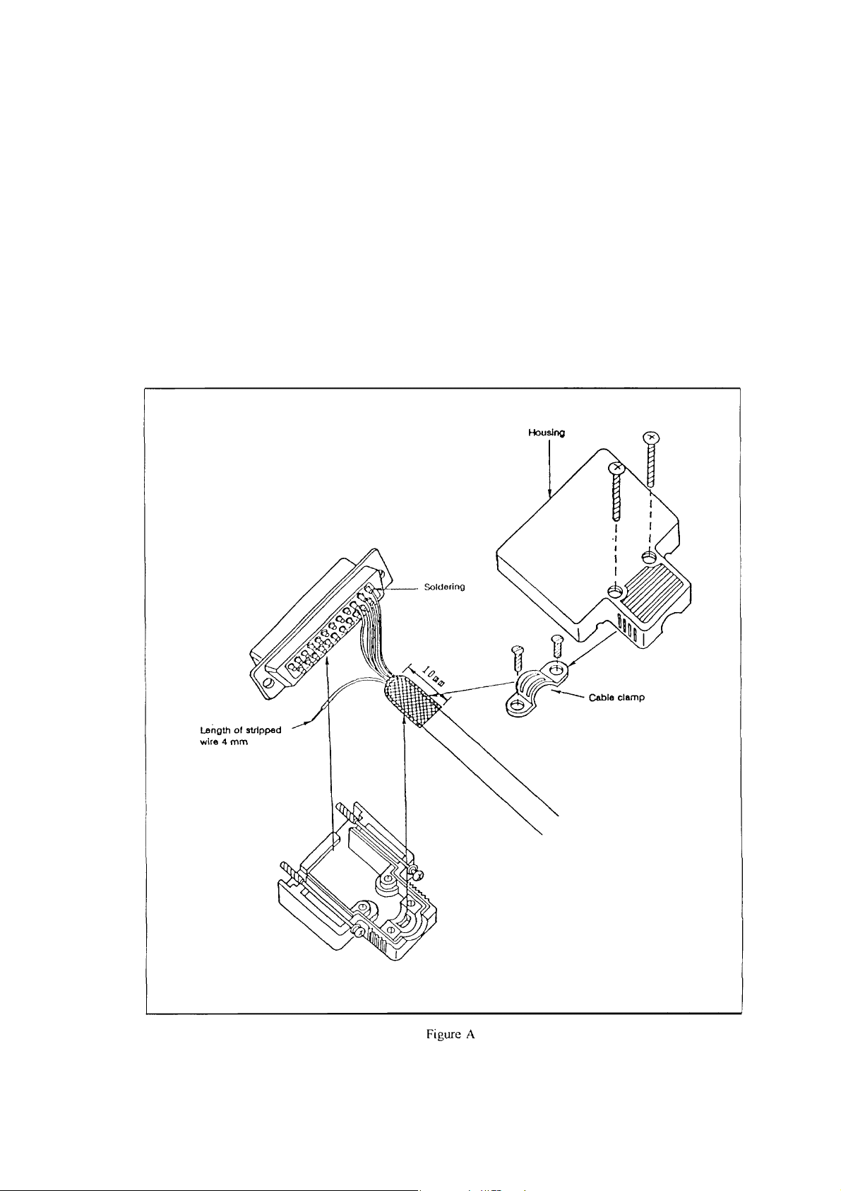
(4) External input/output line/Optional input/output line
Core wires: 0.08 mm
◆
Shield: Ground shield
◆
Cable length: Max. 10 m
◆
Manufacturing method: Refer to Figure A.
◆
Signal ground: Voltage potential between signal ground PGBA and controller
◆
frame ground F.G. must be same.
(5) Serial communication line
Only 1 of 4 serial communication ports (connector name; J1~J4) can be used at the same
◆
time.
Core wires: 0.08 mm
◆
Shield: Ground shield
◆
Cable length: Max. 10 m
◆
Twisted pair: Not required for RS-232C, required for RS-422
◆
Manufacturing method: Refer to Figure A.
◆
2
~ 5.5 mm2
2
~ 5.5 mm2
2
~ 0.5 mm2
2
~ 0.5 mm2
iii
- -
Page 5
(6) Limitation on the robot specifications
Cable length from robot to controller: Max. 8 m
◆
Cable length of teach pendant: Max. 8 m
◆
Optional axis 5: Can not be used.
◆
Optional input/output signals (type; SR-5500IO): Only one optional board can be
◆
Optional relay output signals (type; SR-5500RO): Can not be used.
◆
Optional conveyer tracking system (type; SR-5500CV): Can not be used.
◆
Separated operation panel: Can not be used.
◆
STE 58761
used.
iv
- -
Page 6

STE 58761
This Manual describes how to utilize various robot system functions in order to manually guide
the robot with the teach pendant, edit programs, compile data and carry out automatic operation.
This manual is directed at the robot operator. Before reading this manual, he or she should first
read the Introductory Manual and the Start-up Manual.
v
- -
Page 7
STE 58761
Cautions on Safety
This manual contains the important information on the robot and controller to prevent injury to the
operators and persons nearby, to prevent damage to assets and to ensure correct use.
Make sure that the following details (indications and symbols) are well understood before reading
this manual. Always observe the information that is noted.
[Explanation of indications]
Indication Meaning of indication
This means that "incorrect handling will lead to fatalities or serious injuries."
Danger
!
This means that "incorrect handling may lead to personal injuries *1) or
!
Caution
physical damage *2)."
*1) Injuries refer to injuries, burns and electric shocks, etc., which do not require hospitalization
or long-term medical treatment.
*2) Physical damage refers to damages due to destruction of assets or resources.
[Explanation of symbols]
Symbol Meaning of symbol
This means that the action is prohibited (must not be done).
!
!
!
The details of the actions actually prohibited are indicated with pictures or
words in or near the symbol.
This means that the action is mandatory (must be done).
The details of the actions that must be done are indicated with pictures or
words in or near the symbol.
This means danger.
The details of the actual danger are indicated with pictures or words in or near
the symbol.
This means caution.
The details of the actual caution are indicated with pictures or words in or near
the symbol.
vi
- -
Page 8
[Operation]
STE 58761
Prohibited
!
Danger
!
• During operation, NEVER enter the dangerous area of the robot.
Otherwise, you will be injured seriously.
• DO NOT leave in the working range any machinery or materials which will
hinder the operation. If the equipment went wrong, a person nearby will
be injured or involved in an accident.
• Anyone other than the operator MUST NOT approach the equipment.
Should he negligently touch a dangerous part of the equipment, he will get
injured or involved in a serious accident.
• NEVER perform an inappropriate operation which is not described in the
instruction manual. Otherwise, the equipment will start by mistake,
resulting in personal injury or serious accident.
• If you feel even a little that you are exposed to danger or the equipment
works abnormally, press the EMERGENCY STOP pushbutton switch to
stop the equipment. If the equipment is used as it is, you will be injured or
involved in a serious accident. When this happens, ask our after-sale
service agent for repair.
• During operation, be sure to close the equipment cover. Should the cover
be opened during operation, you will be struck by an electric shock or get
injured.
• Only a well-trained and qualified person is allowed to perform the
operation. Should the equipment be operated improperly, it will start by
mistake, causing a personal injury or serious accident.
Danger
• If the equipment has malfunctioned, turn the power off, identify and remove
the cause of the abnormality, maintain the peripheral equipment and
completely restore the malfunctioned equipment. Then start the
equipment at a low speed. If the equipment starts, leaving the
abnormality, you will be involved in a serious accident.
vii
- -
Page 9
STE 58761
Prohibited
!
Mandatory
!
• DO NOT change the data of the system structure file. Otherwise, the
robot will operate abnormally, resulting in damage or an accident.
• In principle, teaching operation should be performed outside the dangerous
area of the robot. If it should be performed inevitably within the dangerous
area, strictly observe the following matters.
(1) The teaching operation should be always performed by two (2)
persons. One person performs the job and the other person watches
outside the dangerous area. Also, both persons should try to prevent
mis-operation with each other.
(2) The operator should do the job in an attitude ready to press the
EMERGENCY STOP pushbutton switch at any time. Also, he should
perform the job at a position from which he can evacuate immediately
at the time of an emergency after confirming the robot working range
and shields nearby.
(3) The supervisor should keep watch on the job at a position where he
can see the entire robot system and operate the EMERGENCY STOP
pushbutton switch at the time of an emergency. Also, he should keep
• If an abnormality has generated or the POWER LED lamp on the control
anyone from entering the dangerous area. Unless an operator or
other person follows the instructions of the supervisor, accidents will be
caused.
panel remains off after the main power switch of the equipment was turned
on, turn off the main power immediately and confirm the wiring.
Otherwise, you will be struck by an electric shock or a fire will break out.
Caution
• Unless the robot operates toward a designated direction at manual guide,
turn off the servo power. Otherwise, the robot will be damaged or you will
be involved in an accident. When this happens, call us at the after-sale
service agent.
• Pushbutton operations of the control panel and teach pendant should be
confirmed visually. Otherwise, you will be involved in an accident due to
mis-operation.
• Before the hot start in automatic operation, be sure to reset a program. If
the program is executed continuously, the robot will interfere with the
peripheral equipment, resulting in damages or accidents.
viii
- -
Page 10
STE 58761
Mandatory
!
!
Caution
!
• Before operating the equipment, perform the following inspection.
(1) Make sure that visual appearance of the robot, controller, peripheral
equipment and cables is in good condition.
(2) Make sure that no obstacle stands in or near the operating range of the
If the above prior inspection is skipped, the equipment will be damaged or
• The speed of test operation is initially set at 25 % of the maximum robot
• The speed of automatic operation is initially set at 100 % of the maximum
• Once a cold start has been executed, all data saved in the controller
robot and peripheral equipment.
(3) Make sure that the emergency stop and other safety devices operate
properly.
(4) Make sure that no abnormal noise or vibration is involved in the robot
operation.
you will be involved in an accident.
speed.
robot speed.
memory, such as user program, position data, user parameter and system
parameter files are initialized.
Caution
ix
- -
Page 11

TABLE OF CONTENTS
CHAPTER 1 BEFORE OPERATING YOUR ROBOT
1.1
1.2
1.2.1
1.2.2
1.2.3
1.2.4
1.2.5
1.3
1.3.1
1.4
1.4.1
1.4.2
1.4.3
1.4.4
1.4.5
1.4.6
1.4.7
1.5
1.5.1
1.5.2
1.5.3
1.5.4
1.5.5
CHAPTER 2 BASIC OPERATION
2.1
2.2
2.2.1
2.2.2
2.3
2.4
2.5
OVERVIEW OF CONTROL FUNCTIONS・・・・・・・・・・・・
MODE STRUCTURE
External Automatic Mode
Internal Automatic Mode
Manual Mode
Edit
・・・・・・・・・・・・・・・・・・・・・・・・・・・
Test Operation
PRECAUTIONS FOR USE・・・・・・・・・・・・・・・・・・・
Handling Disks
GENERAL OPERATION・・・・・・・・・・・・・・・・・・・・
Use of the Shift key
Use of the Function keys
Repeating an Entry
Correcting Incorrect Entries
Cancelling an Entry
Use of Wild Cards
Format for Operating Instructions
ASSIGNING NAMES
Assigning the Volume Name
Assigning a File Name
Assigning a Point Name
Assigning a Name to Coordinate Data
Assigning a Name to Load Data
BASIC OPERATING PROCEDURE
TURNING ON THE MAIN POWER・・・・・・・・・・・・・・・
Cold Starting
Hot Starting
TURNING ON THE SERVO POWER
TURNING OFF THE SERVO POWER
TURNING OFF THE MAIN POWER
・・・・・・・・・・・・・・・・・・・・・
・・・・・・・・・・・・・・・・・・
・・・・・・・・・・・・・・・・・・
・・・・・・・・・・・・・・・・・・・・・・・
・・・・・・・・・・・・・・・・・・・・・・
・・・・・・・・・・・・・・・・・・・・・・
・・・・・・・・・・・・・・・・・・・・
・・・・・・・・・・・・・・・・・・
・・・・・・・・・・・・・・・・・・・・
・・・・・・・・・・・・・・・・・
・・・・・・・・・・・・・・・・・・・・
・・・・・・・・・・・・・・・・・・・・・
・・・・・・・・・・・・・・・・・・・・・
・・・・・・・・・・・・・・・・・・・
・・・・・・・・・・・・・・・・・・
・・・・・・・・・・・・・・・・・・・・・・・
・・・・・・・・・・・・・・・・・・・・・・・・
STE 58761
・・・・・・・・・・・・・・
・・・・・・・・・・・・・・・・
・・・・・・・・・・・・
・・・・・・・・・・・・・・・
・・・・・・・・・・・・・・・
・・・・・・・・・・・・・・
・・・・・・・・・・・・・・
・・・・・・・・・・・・・・
1-1
1-3
1-4
1-4
1-5
1-6
1-7
1-8
1-8
1-10
1-10
1-11
1-12
1-12
1-12
1-13
1-14
1-15
1-15
1-16
1-17
1-18
1-19
2-1
2-2
2-2
2-4
2-6
2-7
2-8
x
- -
Page 12

CHAPTER 3 MANUAL OPERATION
3.1
3.2
3.3
3.4
3.5
3.6
CHAPTER 4 AUXILIARY SIGNALS
CHAPTER 5 PROGRAM EDITING
5.1
5.2
5.2.1
5.2.2
5.2.3
5.2.4
5.2.5
5.2.6
5.3
5.3.1
5.3.2
5.4
5.4.1
5.4.2
5.4.3
5.4.4
5.5
5.5.1
5.5.2
5.5.3
5.5.4
5.5.5
5.5.6
5.5.7
5.5.8
5.5.9
SELECTING THE MANUAL MODE・・・・・・・・・・・・・・
GUIDANCE COORDINATES
GUIDE MOVEMENT・・・・・・・・・・・・・・・・・・・・・
GUIDE SPEED
GUIDANCE・・・・・・・・・・・・・・・・・・・・・・・・・
SERVO FREE
INVOKING THE SCREEN EDITOR
CHARACTER INPUT・・・・・・・・・・・・・・・・・・・・・
Character Input Mode Selection
Insert Mode
Typeover Mode
Input Deletion
Character Deletion
Moving the Cursor
INPUTTING SCOL COMMANDS・・・・・・・・・・・・・・・・
SCOL Menu
SCOL Menu Selection
EDITOR COMMAND INPUT
Editor Commands
Command Menu Selection
Input Deletion
Cancelling a Command
EDIT COMMAND DESCRIPTIONS
Jump to First Line
Jump to Last Line
Jump to Specified Line
Jump to Previous Page
Jump to Next Page
Jump to Beginning of Line
Jump to End of Line
Set Block
Delete Present Line
・・・・・・・・・・・・・・・・・・・・・・・・
・・・・・・・・・・・・・・・・・・・・・・・・
・・・・・・・・・・・・・・・・・・・・・・・・
・・・・・・・・・・・・・・・・・・・・・・・・・
STE 58761
・・・・・・・・・・・・・・・・・・
・・・・・・・・・・・・・・・
・・・・・・・・・・・・・・・
・・・・・・・・・・・・・・・・・・・・・・
・・・・・・・・・・・・・・・・・・・・・・・
・・・・・・・・・・・・・・・・・・・・・
・・・・・・・・・・・・・・・・・・・・・
・・・・・・・・・・・・・・・・・・・・・・・
・・・・・・・・・・・・・・・・・・・
・・・・・・・・・・・・・・・・・・
・・・・・・・・・・・・・・・・・・・・・
・・・・・・・・・・・・・・・・・
・・・・・・・・・・・・・・・・・・・・・・・
・・・・・・・・・・・・・・・・・・・
・・・・・・・・・・・・・・・
・・・・・・・・・・・・・・・・・・・・・
・・・・・・・・・・・・・・・・・・・・・
・・・・・・・・・・・・・・・・・・・
・・・・・・・・・・・・・・・・・・・
・・・・・・・・・・・・・・・・・・・・
・・・・・・・・・・・・・・・・・
・・・・・・・・・・・・・・・・・・・・
・・・・・・・・・・・・・・・・・・・・
3-1
3-3
3-4
3-5
3-6
3-7
5-1
5-6
5-6
5-7
5-10
5-12
5-13
5-14
5-15
5-15
5-17
5-19
5-19
5-20
5-21
5-22
5-23
5-23
5-25
5-27
5-30
5-32
5-34
5-36
5-38
5-41
xi
- -
Page 13

5.5.10
5.5.11
5.5.12
5.5.13
5.5.14
5.5.15
5.5.16
5.5.17
5.5.18
5.5.19
5.5.20
CHAPTER 6 DATA EDITING
6.1
6.2
6.3
6.3.1
6.3.2
6.4
6.4.1
6.4.2
6.5
6.5.1
6.5.2
6.5.3
6.5.4
6.5.5
6.5.6
6.6
6.6.1
6.6.2
6.6.3
6.6.4
6.6.5
6.6.6
6.6.7
6.6.8
INVOKING THE DATA EDITOR・・・・・・・・・・・・・・・・
EDITOR DATA SELECTION
DATA INPUT・・・・・・・・・・・・・・・・・・・・・・・・・
EDITOR COMMAND INPUT
EDIT COMMANDS COMMON TO EACH DATA EDITING
EDITING POSITIONAL DATA・・・・・・・・・・・・・・・・・
Delete Block
Copy Block
Rename File
Search
Replace
Restore Deleted Line
Repeat
Read in File
Change Editor File
Display Status
Quit
Selecting the Data Input Mode
Moving the Cursor
Editor Commands
Command Menu Selection
Jump to First Line
Jump to Last Line
Jump to Previous Page
Jump to Next Page
Display Status
Quit
・・・・・・・・・・・・・・・・・・・・・・・・・・・
Positional-data Edit-mode Selection
Work Coordinate Selection
Point Name Selection
Teaching Positional Data
Numerical Input of Positional Data
Deleting Positional Data
Point Search
Moving to a Taught Point
STE 58761
・・・・・・・・・・・・・・・・・・・・・・
・・・・・・・・・・・・・・・・・・・・・・・
・・・・・・・・・・・・・・・・・・・・・・
・・・・・・・・・・・・・・・・・・・・・・・・・
・・・・・・・・・・・・・・・・・・・・・・・・
・・・・・・・・・・・・・・・・・・
・・・・・・・・・・・・・・・・・・・・・・・・
・・・・・・・・・・・・・・・・・・・・・・
・・・・・・・・・・・・・・・・・・・
・・・・・・・・・・・・・・・・・・・・・
・・・・・・・・・・・・・・・・・・・・・・・・・・
・・・・・・・・・・・・・・・・・・
・・・・・・・・・・・・・・・
・・・・・・・・・・・・・・・・・・・・・
・・・・・・・・・・・・・・・・・・
・・・・・・・・・・・・・・・・・・・・・
・・・・・・・・・・・・・・・・・
・・・・
・・・・・・・・・・・・・・・・・・・・・
・・・・・・・・・・・・・・・・・・・・・
・・・・・・・・・・・・・・・・・・・
・・・・・・・・・・・・・・・・・・・・
・・・・・・・・・・・・・・・・・・・・・・・
・・・・・・・・・・・・・
・・・・・・・・・・・・・・・・・
・・・・・・・・・・・・・・・・・・・
・・・・・・・・・・・・・・・・・・
・・・・・・・・・・・・・・
・・・・・・・・・・・・・・・・・・
・・・・・・・・・・・・・・・・・・・・・・・
・・・・・・・・・・・・・・・・・・
5-43
5-45
5-48
5-49
5-52
5-57
5-59
5-61
5-65
5-68
5-71
6-1
6-2
6-3
6-3
6-4
6-5
6-5
6-6
6-8
6-8
6-10
6-12
6-14
6-16
6-18
6-20
6-20
6-22
6-25
6-28
6-33
6-36
6-38
6-41
xii
- -
Page 14

6.7
6.7.1
6.7.2
6.7.3
6.7.4
6.7.5
6.7.6
6.7.7
6.8
6.8.1
6.8.2
6.8.3
CHAPTER 7 TEST OPERATION
7.1
7.2
7.3
7.4
7.5
7.6
7.7
7.8
7.9
7.9.1
7.9.2
7.9.3
7.9.4
7.9.5
7.10
7.10.1
7.10.2
7.10.3
7.10.4
7.11
7.12
EDITING COORDINATE DATA・・・・・・・・・・・・・・・・
Coordinate-data Edit-mode Selection
Teaching Coordinate Data
Numerical Input of Coordinate Data
Deleting Coordinate Data
Base Coordinate Selection
Tool Coordinate Selection
Work Coordinate Selection
EDITING LOAD DATA
Load-data Edit-mode Selection
Numerical Input of Load Data
Deleting Load Data
SELECTING THE TEST OPERATION MODE
PROGRAM SELECTION・・・・・・・・・・・・・・・・・・・
OPERATION MODE SELECTION
SPEED OVERRIDE・・・・・・・・・・・・・・・・・・・・・・
SPEED LIMIT
MACHINE LOCK・・・・・・・・・・・・・・・・・・・・・・・
STEP EXECUTION
START-UP
STOP COMMANDS
Cycle Stop
STOP
BREAK
Feed Hold
Emergency Stop
RESET・・・・・・・・・・・・・・・・・・・・・・・・・・・
DIRECT EXECUTION・・・・・・・・・・・・・・・・・・・・
EXITING THE TEST OPERATION MODE
・・・・・・・・・・・・・・・・・・・・・・・・・・
・・・・・・・・・・・・・・・・・・・・・・・・・・
・・・・・・・・・・・・・・・・・・・・・・・・・・
Program Reset
Step Reset
Cycle Reset
Output Signal Reset
STE 58761
・・・・・・・・・・・・・
・・・・・・・・・・・・・・・・・
・・・・・・・・・・・・・
・・・・・・・・・・・・・・・・・・
・・・・・・・・・・・・・・・・・
・・・・・・・・・・・・・・・・・・
・・・・・・・・・・・・・・・・・
・・・・・・・・・・・・・・・・・・・・
・・・・・・・・・・・・・・・
・・・・・・・・・・・・・・・・
・・・・・・・・・・・・・・・・・・・・
・・・・・・・・・・
・・・・・・・・・・・・・・・
・・・・・・・・・・・・・・・・・・・・・・・・
・・・・・・・・・・・・・・・・・・・・・・
・・・・・・・・・・・・・・・・・・・・・・
・・・・・・・・・・・・・・・・・・・・・・・・
・・・・・・・・・・・・・・・・・・・・・・・・
・・・・・・・・・・・・・・・・・・・・・・
・・・・・・・・・・・・・・・・・・・・・
・・・・・・・・・・・・・・・・・・・・・・・
・・・・・・・・・・・・・・・・・・・・・・
・・・・・・・・・・・・・・・・・・・
・・・・・・・・・・・
6-42
6-42
6-44
6-49
6-51
6-55
6-58
6-61
6-63
6-63
6-65
6-67
7-2
7-4
7-6
7-8
7-10
7-12
7-14
7-17
7-20
7-20
7-22
7-23
7-24
7-26
7-27
7-27
7-29
7-31
7-33
7-35
7-37
xiii
- -
Page 15

CHAPTER 8 INTERNAL AUTOMATIC OPERATION
8.1
8.2
8.3
8.4
8.5
8.6
8.7
8.7.1
8.7.2
8.7.3
8.7.4
8.7.5
8.8
8.8.1
8.8.2
8.8.3
8.8.4
8.9
CHAPTER 9 EXTERNAL AUTOMATIC OPERATION
9.1
9.2
9.3
9.4
9.5
9.6
9.7
9.7.1
9.7.2
9.7.3
9.7.4
9.7.5
9.8
SELECTING THE INTERNAL AUTOMATIC MODE・・・・・・・
PROGRAM SELECTION
OPERATION MODE SELECTION・・・・・・・・・・・・・・・
SPEED OVERRIDE
SPEED LIMIT・・・・・・・・・・・・・・・・・・・・・・・・
START-UP
STOP COMMANDS
Cycle Stop
STOP
BREAK
Feed Hold
Emergency Stop
RESET
Program Reset
Step Reset
Cycle Reset
Output Signal Reset
DIRECT EXECUTION
SELECTING THE EXTERNAL AUTOMATIC MODE
PROGRAM SELECTION・・・・・・・・・・・・・・・・・・・
OPERATION MODE SELECTION
SPEED OVERRIDE・・・・・・・・・・・・・・・・・・・・・・
SPEED LIMIT
START-UP
STOP・・・・・・・・・・・・・・・・・・・・・・・・・・・・
Cycle Stop
STOP
BREAK
Feed Hold
Emergency Stop
RESET・・・・・・・・・・・・・・・・・・・・・・・・・・・
・・・・・・・・・・・・・・・・・・・・・・・・・・
・・・・・・・・・・・・・・・・・・・・・・・・
・・・・・・・・・・・・・・・・・・・・・・・・・・
・・・・・・・・・・・・・・・・・・・・・・・・・・
・・・・・・・・・・・・・・・・・・・・・・・・
・・・・・・・・・・・・・・・・・・・・・・・・・・・
・・・・・・・・・・・・・・・・・・・・・・
・・・・・・・・・・・・・・・・・・・・・・・・
・・・・・・・・・・・・・・・・・・・・・・・・
・・・・・・・・・・・・・・・・・・・・・・・・
・・・・・・・・・・・・・・・・・・・・・・・・・・
・・・・・・・・・・・・・・・・・・・・・・・・
・・・・・・・・・・・・・・・・・・・・・・・・・・
・・・・・・・・・・・・・・・・・・・・・・・・・・
・・・・・・・・・・・・・・・・・・・・・・・・
・・・・・・・・・・・・・・・・・・・
・・・・・・・・・・・・・・・・・・・・・・
・・・・・・・・・・・・・・・・・・・・・・
・・・・・・・・・・・・・・・・・・・・・・
・・・・・・・・・・・・・・・・・・・・
・・・・・・・・・・・・・・・・・・・・・
・・・・・・・・・・・・・・・・・・・・・・
STE 58761
・・・・・・・
・・・・・・・・・・・・・・・
8-2
8-4
8-6
8-8
8-10
8-12
8-13
8-13
8-15
8-17
8-18
8-20
8-21
8-21
8-23
8-25
8-27
8-29
9-2
9-4
9-6
9-7
9-8
9-9
9-10
9-10
9-11
9-13
9-14
9-16
9-17
xiv
- -
Page 16

CHAPTER 10 SYSTEM CONTROL
10.1
10.2
10.3
10.4
10.4.1
10.4.2
10.4.3
10.4.4
CHAPTER 11 FILE MANAGEMENT
11.1
11.2
11.3
11.4
11.5
11.6
11.7
11.8
11.9
11.10
CHAPTER 12 UTILITIES
12.1
12.2
12.3
12.4
12.5
CHAPTER 13 SELF DIAGNOSIS
13.1
13.2
13.3
13.4
13.5
13.6
13.7
SETTING THE DATE・・・・・・・・・・・・・・・・・・・・
SETTING THE TIME
CHANNEL SELECTION・・・・・・・・・・・・・・・・・・
RESET
INITIALIZATION・・・・・・・・・・・・・・・・・・・・・・
DIRECTORY DISPLAY
FILE COPY・・・・・・・・・・・・・・・・・・・・・・・・
FILE RENAME
FILE DELETE
FILE LOAD
FILE SAVE
FILE PRINT・・・・・・・・・・・・・・・・・・・・・・・・
BATCH PROCESSING
AUTOMATIC EXECUTION FILES・・・・・・・・・・・・・・
SELECTING THE UTILITY MODE・・・・・・・・・・・・・・
WORK COORDINATE SELECTION
TOOL COORDINATE SELECTION
PRESENT POSITION MONITOR
EXTERNAL I/O SIGNAL MONITOR
CLASSIFICATION OF ERRORS
ERROR DISPLAYS・・・・・・・・・・・・・・・・・・・・
ERROR MESSAGE DISPLAYS
ERROR RESETTING・・・・・・・・・・・・・・・・・・・・
ALL ERRORS RESET
ERROR HISTORY DISPLAYS
LIST OF ERRORS
・・・・・・・・・・・・・・・・・・・・・・・・・・
Program Reset
Step Reset
Cycle Reset
Output Signal Reset
・・・・・・・・・・・・・・・・・・・・・・・・
・・・・・・・・・・・・・・・・・・・・・・・・
STE 58761
・・・・・・・・・・・・・・・・・・・・
・・・・・・・・・・・・・・・・・・・・・
・・・・・・・・・・・・・・・・・・・・・・・
・・・・・・・・・・・・・・・・・・・・・・
・・・・・・・・・・・・・・・・・・・
・・・・・・・・・・・・・・・・・・・
・・・・・・・・・・・・・・・・・・・・・・・
・・・・・・・・・・・・・・・・・・・・・・・
・・・・・・・・・・・・・・・・・・・
・・・・・・・・・・・・・
・・・・・・・・・・・・・・
・・・・・・・・・・・・・・・
・・・・・・・・・・・・・
・・・・・・・・・・・・・・・
・・・・・・・・・・・・・・・
・・・・・・・・・・・・・・・・・・・
・・・・・・・・・・・・・・・・
・・・・・・・・・・・・・・・・・・・・・
10-1
10-4
10-7
10-10
10-10
10-12
10-14
10-16
11-1
11-4
11-7
11-11
11-14
11-17
11-20
11-23
11-26
11-30
12-1
12-2
12-4
12-6
12-8
13-1
13-1
13-2
13-4
13-5
13-6
13-8
xv
- -
Page 17

CHAPTER 14 JOINT LIMIT SETTING
14.1
14.2
14.3
APPENDIX A
APPENDIX B
APPENDIX C
SELECTING JOINT LIMIT SETTING MODE・・・・・・・・・・
JOINT LIMIT TEACHING
INPUTTING NUMERIC VALUES FOR JOINT LIMITS・・・・・・
TEACH PENDANT MESSAGE TABLE
LIST OF COMMANDS
HANDLING ARRAY DATA BY DATA EDITING・・・・・・
STE 58761
・・・・・・・・・・・・・・・・・・
・・・・・・・・・・
・・・・・・・・・・・・・・・・・
14-1
14-3
14-5
15-1
15-10
15-13
xvi
- -
Page 18

CHAPTER 1
BEFORE OPERATING YOUR ROBOT
1.1 OVERVIEW OF CONTROL FUNCTIONS
Function Description
Main power ON/OFF Used to turn the main power on or off.
Servo power ON/OFF Use to turn the power for the servo on or off.
Master mode selection
Start-up and stop Used to start up or stop automatic operation.
Cycle completion
Feed hold Used to temporarily stop automatic operation.
Emergency stop Used to immediately stop automatic operation.
Manual operation
Auxiliary signal
operation
Program editing Used to create and edit programs.
Data editing
File management
Reset
Date setting Used to set the data for use by the system.
The setting Used to set the time for use by the system.
Channel selection Used to select a communication channel.
Error display
Error reset Used to reset errors that have been corrected.
Error history display
Work coordinate
selection
Tool coordinate
selection
Used to select either the Manual Mode, the External
Automatic Mode or the Internal Automatic Mode.
Used to stop automatic operation (after the
completion of one cycle).
Used to manually guide the robot by jogging, inching
and other such movement.
Used to control pneumatic drive shafts (for grippers,
etc.)
Used to create and edit positional data, coordinate
data and load data.
Used to manage files by such operations as loading,
saving, copying and deleting.
Used to reset output signals and execution
conditions.
Used to display errors which have not yet been
reset.
Used to display a historical list of errors which have
been corrected.
Used to select a work coordinate system.
Used to select a tool coordinate system.
Control
Panel
STE 58761
Teaching
pendant
〇
△
〇
(On only)
〇
〇
〇
〇
〇
〇
〇
〇
〇
〇
〇
〇
〇
〇
〇
〇
〇
〇
〇
〇
〇
〇
External
control
signals
〇
〇
〇
〇
〇
1-1
- -
Page 19

Function Description
Present position
monitor
External I/O signal
monitor
File selection Used to select a file for execution.
Move Moves the robot to a point which has been taught.
Used to display the present position of the robot in
terms of the various coordinate system.
Used to display the status of digital I/O signals.
Control
Panel
〇
△
STE 58761
External
control
signals
〇
Teaching
pendant
: Complete operation
: Partial operation
〇
〇
〇
〇
1-2
- -
Page 20

STE 58761
1.2 MODE STRUCTURE
External Automatic
Mode (EXT)
Master Mode
Utility Mode The Utility Mode is used to perform such operations
Error Display Mode The error display mode is used to display and reset
The emergency stop and servo off operations can be used regardless of the present mode.
Internal Automatic
Mode (INT)
Manual Mode (MANU) The Manual Mode is used to perform such
The External Automatic Mode is used to
automatically operate the robot by program. This
operation is performed with external control signals
or signals from a host computer.
The Internal Automatic Mode is used to
automatically operate the robot by program. This
operation is carried out from either the control panel
or the teach pendant.
operations as teaching, guiding, file management
and program test runs. All such operations are
carried out with the teach pendant.
as coordinate selection, position monitoring and
signal monitoring. The Utility Mode is carried out
from the teach pendant and is unrelated to the
master mode.
errors with the teach pendant. The error display
mode has nothing to do with the Master Mode.
1-3
- -
Page 21

STE 58761
1.2.1 External Automatic Mode
External Operation
Signal Mode (SIG)
External
Automatic
Mode (EXT)
The mode with which external automatic operation is carried out is defined in
Host Mode (HOST) This mode is used to perform the program
the system configuration file. See the Start-up Manual for details.
All file selections, execution mode selections, speed override settings and
speed limit settings made in either the Internal Automatic Mode or the Test
Operation Mode are also valid in the External Automatic Mode.
1.2.2 Internal Automatic Mode
Program Selection
(SELECT)
Internal
Automatic
Mode (INT)
Operation Mode
Selection (MODE)
Speed Override
(MSPEED)
Speed Limit
(LSPEED)
Start-up Starts program execution from the control panel.
Stop (STOP,BREAK) Suspends or cancels program execution.
Direct Execution
(DO)
Reset (RESET) Resets the program execution step, variables and
This mode is used to perform the program automatic
operation. This operation is carried out with
external operation signals. For details, see the
Interface Manual.
automatic-operation, file uploading and file
downloading. All operations are carried out by the
host computer through serial communication
channel(s). For details, see the Communications
Manual.
Selects a program for execution.
Selects an operation mode.
Selects the speed override.
Selects the speed limit.
Directly executes a SCOL command.
digital output signals.
1-4
- -
Page 22

1.2.3 Manual Mode
Edit (EDIT) Edits programs and data (positional data, coordinate
Test Operation
(TESTRUN)
Manual
Mode
(MANU)
File Load (LOAD) Loads a file from the disk into the RAM drive.
File Save (SAVE) Saves a file in the RAM drive onto the disk.
Disk Initialization
(FORMAT)
Directory Display
(DIR)
File Copy (COPY) Copies a file in the RAM drive and stores the copy in
File Comparison
(VERIFY)
File Renaming (REN) Renames a file.
File Deletion (DEL) Deletes an unneeded file.
File Printing (PRINT) Prints out the contents of a file on a printer.
Date Setting (DATE) Sets the current date.
Time Setting (TIME) Sets the current time.
Channel Selection
(CHANNEL)
Reset (RESET) Resets the program execution step, variables and
Guidance In conjunction with the control key, the guide teach
STE 58761
data and load data).
Checks to see that programs run properly.
Formats either the disk or the RAM drive.
Displays a list of all the files contained in either the
RAM drive or the disk.
a separate file.
Compares the contents of two files in units of bytes
to see that they are the same.
Switches over between serial channels.
digital output signals.
speed key and the guide coordinate key, the guide
keys are used to move the end effecter. Guidance
is effective only in the Manual Mode; it is not
effective in the Test Operation Mode.
1-5
- -
Page 23

1.2.4 Edit
Editing
Screen editor Program editing
Programs and global data are created and edited by
entering and deleting characters, by selecting
command menus and by selecting SCOL menus.
Data editor
Positional data editing
Positional data are created and edited by teaching
and by entering numbers. Work coordinate
systems are selected; work coordinates are edited.
Coordinate data editing
Coordinate data are created and edited by teaching
and by entering numbers. Base coordinates and
tool coordinates are selected. Work coordinates
are specified.
Load data editing
Load data are created and edited by entering
numbers.
STE 58761
1-6
- -
Page 24

1.2.5 Test Operation
Program Selection
(SELECT)
Operation Mode
Selection (MODE)
Speed Override
(MSPEED)
Speed Limit (LSPEED) Sets the speed limit.
Te st
Operation
(TESTRUN)
Machine Lock
(MACHINE)
Step Execution
(STEP)
Start-up (RUN) Starts program execution from a desired step in the
Stop (STOP,BREAK) Suspends or cancels program execution.
Direct Execution
(DO)
Reset (RESET) Resets the program execution step, variables and
STE 58761
Selects a program for execution.
Selects an operation mode.
Selects the speed override.
Enables and disables the machine lock.
Executes the program one step at a time.
program.
Directly executes a SCOL command.
digital output signals.
1-7
- -
Page 25

1.3 PRECAUTIONS FOR USE
For the connection of FDD unit (option), see the Interface Manual.
1.3.1 Handling Disks
(1) General precautions
(a) Don’t open the shutter section. The disk will be unusable should
any dirt get on the magnetic surface.
' I~
(b) Keep away from speakers or other devices which create strong
magnetic fields. If you don't, the contents of your disks may get
erased.
(c) Keep out of direct sunlight and away from hot objects.
(d) Don't stack books or folders on top of a disk.
A
(e) Stick the label on in the correct position. If you put on a new label,
be sure to take the old label off first.
(f) Store your disk in a location having the following temperature and
humidity range:
Storage temperature : 4 to 53°C
Storage humidity : 8 to 90 %
STE 58761
1-8
- -
Page 26

(2) Inserting a disk
(3) Removing a disk
(4) Disk write protection
STE 58761
(a) With the label up and the metal shutter forward, insert
the disk straight and slowly into the slot until you
hear it click into place.
(a) Push the push button. The floppy disk should pop
out a little ways from the slot.
(b) Grip the disk with your fingers at the label section
and draw it straight out.
Caution
!
Do not try to remove the disk while the disk
drive light is still lit. Data is either being
written to or read from the disk while the light is
lit, and if you remove the disk at this time you
may lose or damage your files.
All 3.5" disks have a write protect tab to prevent files
from being accidentally erased.
(a) Write protect
Slide the write protect tab toward the edge of the
disk (protect position).
(b) Write enable
Slide the write protect tab away from the edge of the
disk (write position).
1-9
- -
Page 27

1.4 GENERAL OPERATION
Only one key can be input at a time with the teach pendant.
1.4.1 Use of the Shift Key
When a key is pushed while the "shift" key is held down, the upper character on that key
will be input.
(1) Entering the lower character
To enter the lower character on a key, simply push that key.
Example) Entering the character "9".
Key operation Display
(2) Entering the upper character
To enter the upper character, push down that key while holding down the "shift" key.
Example) Entering the character "(".
Key operation Display
+
Shift
(
9
(
9
9
STE 58761
9
1-10
- -
Page 28

1.4.2 Use of the Function Keys
In order to make it easier to input data, the teach pendant is provided with six function
keys, i.e., "F1" to "F6".
The functions to which "F1" to "F5" correspond will change depending on the mode. The
names of these functions will appear above the corresponding function key. By pushing
the appropriate key, commands can be executed without having to type in each letter
making up that command.
The "F6" key is the NEXT key. When there are more than five commands in a particular
mode, the NEXT key allows one to display the additional commands.
Example: Selecting the "SAVE" command
> ■
EDIT LOAD SAVE TESTRUN> RESET NEXT
F1 F2 F3 F4 F5 F6
STE 58761
Command names followed by a “>” symbol indicate commands which are executed
immediately when the, corresponding function key is pushed.
Caution
!
The function keys work differently when editing with the screen editor or data editor. For
more information, refer to Chapter 5 "Program Editing" and Chapter 6 "Data Editing."
1-11
- -
Page 29

1.4.3 Repeating an Entry
The repeat operation is available for the following keys.
[Bs], [Esc], [Exec]
Guide key
[Move]
Cursor keys
[Coordinates], [Teach Speed], [Control]
1.4.4 Correcting Incorrect Entries
Use the "Bs" key to erase any characters which were incorrectly entered.
Example:
(Correct) TIME 13:50:00 (Incorrect) TIME 13:60:__
Push the “Bs” key. TIME 13:6__
Push the “Bs” key. TIME 13:__
Keep on pushing the “Bs” key until the incorrect characters are erased. Then type in the
correct characters.
STE 58761
Caution
!
The "Ins", "Del" and cursor keys may not be used when entering a command.
1.4.5 Cancelling an Entry
If you wish to cancel the command you are entering, simultaneously push the "ESC" key.
This will cancel the command you entered and allow you to write the next command on
the following line.
Should an error message or other such message appear while entering a command, that
command line will be negated.
1-12
- -
Page 30

1.4.6 Use of Wild Cards
You may use the wild cards * and ? when specifying files with the directory [DIR], delete
[DEL], print [PRINT], file save [SAVE] or file load [LOAD] command.
Wild cards are used to simultaneously specify multiple files. Using wild cards correctly
can save time and increase efficiency when specifying files.
(1) The asterisk wild card”*”
The asterisk wild card (*) can take the place of a file name or an extension. For
example, the specification “A*.*” refers to all files having a name starting with A and
having any type of extension (or no extension at all). All of the following files would
apply:
ADATA. BAT
ABC.PAR
AFILE
(2) The question mark wild card "?"
The question mark wild card "?" can take the place of any single character in a name or
extension. For example, the specification “A??.*” refers to all files that have a name
starting with A, are three characters long or less. A space or null character is also
treated as one character. All of the following files would apply:
ABC.PAR
ACD.DAT
AAA
In order to be able to use wild cards effectively, you should pay attention to how you assign
file names and extensions.
STE 58761
1-13
- -
Page 31

1.4.7 Format for Operating Instructions
The following format is used in this manual to explain how to use commands.
Title [command name]
(1) Function
Explains the purpose of the command and what it does.
(2) Input format
Explains the input format for operation. An input consists of a command and
parameters. Listed below are notation used to describe the input format.
[ ] Indicates an item (or items) that may be specified if necessary and omitted if not.
< > Indicates an item (or items) to be input.
<d:> Specifies the drive name. One must enter either A or R.
A : FDD unit (option)
R : RAM drive
<file name> Specifies the file name. <file name> may consist of a name having up to
eight alphanumeric characters and an extension having up to three characters. For
example, CONSTRUC.SYS is a valid <file name>.
{ } Indicates that one parameter is to be chosen from among the multiple parameters
enclosed.
... Indicates that multiple parameters may be specified.
Note that the characters [ ], < >, { } and ... are themselves not to be entered.
They are merely symbols use to describe the input format.
(3) Comments
Explains restrictions and things to keep in mind.
(4) Procedure
Explains procedures and system responses for various operations.
(5) Related functions
Explains related functions.
STE 58761
1-14
- -
Page 32

1.5 ASSIGNING NAMES
1.5.1 Assigning the Volume Name
When a disk is initialized, you can assign a name to that disk. This is the volume name.
In order to simplify disk handling, you should keep your files sorted by task and put related
files on the same disk. Also, be sure to give the disk a descriptive, easy to understand
name.
The volume name can be checked by looking at the directory display.
Volume names consist of a volume name proper, a period, and a volume name extension.
An example is shown below:
WORK1
The following characters may be used in the volume name and its extension:
Alphabetic characters: A to Z
Numerals: 0 to 9
The volume name extension may be omitted. In such a case, the period becomes
unnecessary.
. FIL
STE 58761
FIL is the volume name extension.
It may have up to three characters.
A period is used to separate the volume name
and the volume name extension.
WORK1 is the volume name. It may have up to
six characters.
1-15
- -
Page 33

1.5.2 Assigning a File Name
Every file in a disk or in the RAM drive has its own name. This is called the file name.
File names consists of a file name proper, a period, and a file name extension. An
example is shown below:
CONSTRUC
The following characters may be used in the file name and its extension:
Alphabetic characters: A to Z
Numerals: 0 to 9
The file name extension is used to identify the nature (type) of the file. By using different
extensions on the same file name, you can keep related files together while still being able
to differentiate between them by purpose.
The following extensions are used for the following type of special purpose files.
Extension Purpose
STE 58761
. SYS
SYS is the file name extension. It may have up
to three characters.
A period is used to separate the file name and
the file name extension.
CONSTRUC is the file name. It may have up to
eight characters.
SYS Identifies system files.
BAT Identifies batch files.
PAR Identifies parameter files.
LIB Identifies library files.
LOG Identifies maintenance files.
The file name extension may be omitted. In such a case, the period becomes
unnecessary.
When specifying a file having a file name extension, you may not omit that extension. If
you do, the controller will treat that file as a completely different file.
1-16
- -
Page 34

1.5.3 Assigning a Point Name
When entering positional data for a point, you have to assign a name to that point. This
name will be used later in the program when telling the robot where to go.
Point names generally have a format like that shown in the example below:
PNT100
The following characters may be used in the point name. (The first letter of a point name
must be an alphabetic character.)
Alphabetic characters: A to Z
Numerals: 0 to 9
Note: You may not use an identifier reserved for the SCOL language to name a point.
See Appendix B of Robot Language Manual for a list of such identifiers
(reserved words).
If you try to enter more than ten characters when inputting a point name, an error
message ("name over") will be displayed and that entry will be invalidated.
If you try to enter anything other than an alphabetic character for the first character of the
point name, an error message ("illegal key!") will be displayed and that entry will be
invalidated.
If you try to enter anything other than an alphanumeric character when inputting the point
name, an error message ("illegal key!") will be displayed and that entry will be invalidated.
STE 58761
PNT100 is the point name (in this example).
The point name may have up to ten characters.
1-17
- -
Page 35

1.5.4 Assigning a Name to Coordinate Data
When entering coordinate data for a work coordinate system, a tool coordinate system or
the base coordinate system, you have to assign a coordinate name to that data. This
name will be used later in the program when telling the robot which coordinate system to
use.
Coordinate names generally have a format like that shown in the example below:
TAB L E 1
The following characters may be used in the coordinate name. (The first letter must be
an alphabetic character.)
Alphabetic characters: A to Z
Numerals: 0 to 9
Note: You may not use an identifier reserved for the SCOL language to name
coordinate data. See Appendix B of Robot Language Manual for a list of such
identifiers (reserved words).
If you try to enter more than ten characters when inputting a coordinate name, an error
message ("name over") will be displayed and that entry will be invalidated.
If you try to enter anything other than an alphabetic character for the first character of the
name, an error message ("illegal key!") will be displayed and that entry will be invalidated.
If you try to enter anything other than an alphanumeric character when inputting the name,
an error message ("illegal key!") will be displayed and that entry will be invalidated.
STE 58761
TABLE1 is the coordinate name (in this example).
The name may have up to ten characters.
1-18
- -
Page 36

1.5.5 Assigning a Name to Load Data
When entering load data, you have to assign a load name to that data. This name will be
used later in the program when telling the robot which load value to use.
Load names generally have a format like that shown in the example below:
SAMPLE1
The following characters may be used in the load name. (The first letter must be an
alphabetic character.)
Alphabetic characters: A to Z
Numerals: 0 to 9
Note: You may not use an identifier reserved for the SCOL language to name load
data. See Appendix B of Robot Language Manual for a list of such identifiers
(reserved words).
If you try to enter more than ten characters when inputting a load name, an error message
("name over") will be displayed and that entry will be invalidated.
If you try to enter anything other than an alphabetic character for the first character of the
name, an error message ("illegal key!") will be displayed and that entry will be invalidated.
If you try to enter anything other than an alphanumeric character when inputting the name,
an error message ("illegal key!") will be displayed and that entry will be invalidated.
STE 58761
SAMPLE1 is the load name (in this example).
The name may have up to ten characters.
1-19
- -
Page 37

STE 58761
CHAPTER 2
BASIC OPERATION
2.1 BASIC OPERATING PROCEDURE
The following flowchart shows the basic operating procedure for automatic operation. It covers
all operations from turning on the power to turning off the power.
START
Turn on main power
Turn on servo power
NO
program
edit end?
YES
Automatic operation
Job End?
YES
Turn off servo power
Turn off main power
END
NO
NO
edit
Test run
operation
Correct?
YES
2-1
- -
Page 38

STE 58761
2.2 TURNING ON THE MAIN POWER
There are two ways to start up the controller - cold starting and hot starting. Normally, only the
hot starting is required. For details, see Para. 2.2.2.
2.2.1 Cold Starting
Danger
!
If an abnormality has generated or the POWER LED lamp on the control panel remains off after
the main power switch of the equipment was turned on, turn off the main power immediately
and confirm the wiring. Otherwise, you will be struck by an electric shock or a fire will break
out.
Caution
!
Once a cold start has been executed, all data saved in the controller memory, such as user
program, position data, user parameter and system construction files are initialized.
(1) Function
System programs contained on a disk inserted in the FDD unit (option) are loaded into
the RAM drive. The RAM drive is thereby initialized and the controller is booted
(started up).
(2) Input format: None
(3) Comments
Normally, you should hot start the system. Only cold start the system when you cannot
・
hot start it.
After you have completed a cold start, remove the system disk from the controller disk
・
drive. Should you leave the system disk in the disk drive, all the files in the RAM drive
will be erased should the power go out and turn back on again.
Copies of all files necessary for the RAM drive should be kept on disks for safekeeping.
・
For information on how to save files on disks, see the Section "Saving files."
The system disk must contain the following system programs and subscription files.
・
System programs:
SVPMTX. SYS
MCPMTX. SYS
Subscription files:
CONSTRUC. SYS EXTRNSEL. SYS *
ALARM. MES * SCOL. LIB *
SYSTEM. PAR AUTOSTR. BAT *
USER. PAR
2-2
- -
Page 39

STE 58761
Files marked by an asterisk are not absolutely necessary to run the system. However,
you will get an error if you try to execute a function dependent on a missing file.
For more information on these files, see the Start-up Manual.
(4) Procedure
(a) Step 1: Insert the system disk
Insert the system disk into the FDD unit (option).
(b) Step 2: Turn on the main power.
Turn on the main power switch located on the controller.
The POWER lamp and SERVO POWER OFF lamp should light up.
10AT
POWER
The light on the disk drive should also light up around this time. This shows
that the system programs are being loaded into the RAM drive. While these
programs are being loaded, the START lamp on the control panel blink.
When loading is complete, the SERVO POWER OFF lamp, the START lamp,
the STOP and the CYCLE STOP lamp will all momentarily light up at once.
The LCD (liquid crystal display) of the teach pendant will display the initial mode
selection menu. The STOP lamp and the SERVO POWER OFF lamp on the control
panel will be lit.
Following this, parameters will be automatically read in from the disk in the disk drive.
When this is completed, the disk drive light will go out. This marks the end of the
cold start operation.
(c) Step 3: Remove the system disk
Once the cold start is completed, the system is booted and ready to operate.
After checking to make sure that the disk drive light is out, remove the system
disk from the disk drive.
The lamp
turns on
POWER
FAULT
EXT
SERVO POWER
OFF
STOP START
INT
MANU
EMERGENCY
ON
BATTERY
ALARM
CYCLE
STOP
2-3
- -
Page 40

STE 58761
2.2.2 Hot Starting
Caution
!
If an abnormality has generated or the POWER LED lamp on the control panel remains off after
the main power switch of the equipment was turned on, turn off the main power immediately
and confirm the wiring. Otherwise, you will be struck by an electric shock or a fire will break
out. When hot starting has been done, the controller enters a program reset status.
(1) Function
Starts up the controller with files contained in the RAM drive.
(2) Input format
None
(3) Comments
The following subscription files must be in the RAM drive:
CONSTRUC. SYS EXTRNSEL. SYS *
ALARM. MES * SCOL . LIB *
SYSTEM. PAR AUTOSTR. BAT *
USER. PAR
Files marked by an asterisk are not absolutely necessary to run the system.
However, you will get an error should you try to execute a function dependent
on a missing file.
For more information on these files, see the Start-up Manual.
2-4
- -
Page 41

10AT
STE 58761
(4) Procedure
(a) Step 1: Turn on the main power
First, make sure that the system disk is not in the FDD unit (option). Then,
turn on the controller main power. The POWER lamp and the SERVO
POWER OFF lamp on the control panel will light up.
The lamp
POWER
turns on
POWER
FAULT
EXT
INT
SERVO POWER
OFF
STOP START
MANU
ON
CYCLE
STOP
EMERGENCY
BATTERY
ALARM
The controller will start initializing the system. The disk drive light will blink for
about 15 seconds.
When the hot start operation is completed, the STOP lamp on the control panel will
light up and the LCD (liquid crystal display) of the teach pendant will display the
initial mode selection menu.
2-5
- -
Page 42

2.3 TURNING ON THE SERVO POWER
Caution
!
If the robot moves abnormally at the servo power ON, press the EMERGENCY STOP
・
switch immediately to turn the servo power off.
If anyone enters the robot dangerous area, turn the servo power off beforehand.
・
(1) Function
Turns on the main power circuit for the servo drivers. Servo control axes will
change over to the servo-lock state, and any brakes will be released.
(2) Input format: None
(3) Comments
You will not be able to turn on the servo power if the emergency switch is pushed
down. Release the switch first.
In order to turn on the servo power with an external operation signal, the teach pendant
connector (or the dummy connector) must be attached to the control panel. Also, the
contacts for the Emergency Stop and Servo OFF external signals must be open. For
more information, refer to the Interface Manual.
(4) Procedure
(a) Step 1: Turn on the servo power
Push either the SERVO POWER ON switch on the controller or the teach pendant.
The controller SERVO POWER ON lamp should turn on and the OFF lamp should
turn off. The teach pendant SERVO ON lamp should light up.
STE 58761
2-6
- -
Page 43

2.4 TURNING OFF THE SERVO POWER
(1) Function
Turns off the main power circuit for the servo drivers. Servo control axes will
change over to the servo-free state, and any brakes will be activated.
(2) Input format: None
(3) Comments
Do not turn the servo power off while the robot is running. When you wish to stop
the robot in a hurry, push an emergency stop switch instead.
When about to enter the robot work-space envelope, or when no operator is to be present,
turn off the servo power for safety reasons. (Note that this does not apply to automatic
operation.)
For information on how to turn off the servo power with an external operation signal, see
the Interface Manual.
(4) Procedure
(a) Step 1: Turn off the servo power
Push the SERVO POWER OFF switch on the controller. The SERVO POWER
OFF lamp should turn on and the ON lamp should turn off. The teach pendant
SERVO ON lamp should turn off.
The lamp
turns on
STE 58761
2-7
- -
Page 44

2.5 TURNING OFF THE MAIN POWER
(1) Function
Turns off the main power and stops controller processing.
(2) Input format: None
(3) Comments
Do not turn off the main power while the servo power is on or while the controller is
either processing data or manipulating files. Before turning off the main power,
make sure that the servo power is off and that the controller is not running.
(4) Procedure
(a) Step 1: Remove the disk, if any, from the disk drive
If there is a disk in the FDD unit (option), check to see that the disk drive light is off
and then remove the disk.
(b) Step 2: Turn off the main power
Turn off the main power switch located on the controller.
10AT
The POWER lamp on the controller should turn off.
POWER
The lamp
turns off
POWER
FAULT
EXT
SERVO POWER
OFF
STOP START
INT
MANU
STE 58761
EMERGENCY
ON
BATTERY
ALARM
CYCLE
STOP
2-8
- -
Page 45

CHAPTER 3
MANUAL OPERATION
3.1 SELECTING THE MANUAL MODE
(1) Function
Changes over to the Manual Mode in which the robot is manually guided, points
are taught, files are managed and the system is controlled. All of these
operations are performed with the teach pendant.
(2) Input format
None
(3) Comments
The Test Operation Mode is classified as a manual mode. However, the Test
Operation Mode is treated as completely separate in this manual.
For information on the Test Operation Mode, see Chapter 7,"Test Operation."
(4) Procedure
(a) Step 1: Select the Manual Mode
Turn the master mode switch on the control panel to MANU. The following menu
should appear on the teach pendant display.
> ■
----- (a)
EDIT LOAD SAVE TESTRUN> RESET NEXT ----- (b)
STE 58761
3-1
- -
Page 46

a) Display field for command input and messages
b) Display field for function key menu
EDIT Edit
LOAD File load
SAVE File save
TESTRUN Test operation
RESET Reset
DIR Directory display
COPY File copy
DEL File deletion
REN File renaming
PRINT File printing
FORMAT Disk initialization
VERIFY File comparison
ZEROP Zero point teaching
JLMIT Soft limit teaching
CHANNEL Channel selection
DATE Date setting
TIME Time setting
STE 58761
3-2
- -
Page 47

STE 58761
3.2 GUIDANCE COORDINATES
(1) Function
Selects a coordinate system in which to guide the robot from among the joint
coordinates, tool coordinates, work coordinates and world coordinates.
(2) Input format
None
(3) Comments
Refer to the Introductory Manual for information on robot coordinate systems.
If a tool, base or work coordinate system has not been taught to the robot, the
robot will assume:
(a) The tool coordinate system coincides with the surface of the hand mounting flange.
(b) The work and world coordinate systems coincide with the base coordinate system.
When using the tool or work coordinate system, make sure you have selected the
right one.
(4) Procedure
(a) Step 1: Select the tool and work coordinates
It is possible to have several work and/or tool coordinate systems. Therefore, you
must select which ones you are going to use with the WORK and TOOL utilities.
For details, see Chapter 12, "Utilities."
If you are using joint or world coordinates, this operation is unnecessary.
(b) Step 2: Select the coordinates
Push the "Coordinate" key on the teach pendant. Each time you push this key,
the lamp will cycle one step between World, Work, Tool and Joint.
The initial setting is Joint.
3-3
- -
Page 48

STE 58761
3.3 GUIDE MOVEMENT
There are three types of guide movement: jog, inching and free.
In the jog mode, the robot will move in the specified direction at the specified speed in the
specified coordinate system for as long as you hold down the corresponding guide key. The jog
mode is useful for rough positioning of the robot to get it near the target position.
In the inching mode, the robot will move in the specified direction at the specified displacement in
the specified coordinate system. The inching mode is useful for fine positioning of the robot near
the target position.
In the free mode, you may release the servo lock on the desired axes and move around the robot
by hand. The free mode is useful for fine positioning of the robot near workpieces and other
such objects.
(1) Function
Selects the guide movement mode.
(2) Input format: None
(3) Comments
When changing from the free mode to another mode, the servo mechanism on all
axes will lock-up (change to the locked state).
(4) Procedure
(a) Step 1: Select the Manual Mode
Turn the master mode switch on the control panel to "MANU".
(b) Step 2: Select the guide movement mode
Push the "Control" key on the teach pendant. Each time you push this key, the
lamp will cycle one stop between Jog, Inching and Free.
The initial setting is Jog.
3-4
- -
Page 49

3.4 GUIDE SPEED
(1) Function
Selects the guide speed or the guide displacement.
Guide speed will be set if the guide movement mode is set to jog. Guide
displacement will be set if the guide movement mode is set to inching.
Set the guide speed or guide displacement in accordance with how far the robot is from the
target position.
(2) Input format: None
(3) Comments: None
(4) Procedure
(a) Step 1: Select the guide speed mode
Push the "Teach Speed" key on the teach pendant. Each time you push this key,
the lamp will cycle one step between High, Med. and Low.
The initial setting is Low.
STE 58761
3-5
- -
Page 50

3.5 GUIDANCE
Caution
!
If the guidance is performed manually, do not enter the robot dangerous area.
・
If the robot moves abnormally, immediately effect an emergency stop.
・
If the robot will not move in the specified direction, consult Toshiba Machine.
・
(1) Function
The robot can be moved in the desired direction by pushing the appropriate guide
keys when the guide movement mode is set to inching or jog.
(2) Input format
The guidance coordinates, guide movement mode and guide speed do not have to
be set in any particular order. However, they all must be set before pushing any
guide keys.
(3) Comments
When the guide movement mode is set to free, the guide keys do not specify the
direction the robot is to move; rather, they specify axes for which the servo lock is
to be released.
The guide keys will only work while at least one of the deadman switches (on the back of
the teach pendant) is pushed down. This is to prevent accidents.
(4) Procedures
(a) Step 1: Select the Manual Mode
Turn the master mode switch on the control panel to "MANU".
(b) Step 2: Set the guidance conditions
Set the guidance conditions (guidance coordinates, guide movement and guide
speed) as necessary.
(c) Step 3: Guidance
Push the guide keys as appropriate while holding down at least one deadman
switch (on the back of the pendant). The robot will move as directed in the
specified coordinate system.
STE 58761
3-6
- -
Page 51

3.6 SERVO FREE
(1) Function
Servo locks can be released for axes as desired when the guide movement mode
is set to free. Axes in the servo free (i.e., unlocked) state can be moved freely by
hand. This is convenient when moving the robot near workpieces and other such
objects.
(2) Input format
None
(3) Comments
If You change from the servo free state to either the Test Operation Mode, the
Internal Automatic Mode or the External Automatic Mode, the servo lock will be set
for all axes.
The guide keys will only work while at least one of the deadman switches (on the back of
the teach pendant) is pushed down.
If you move the robot by hand in the servo free state, other joints may move as well due to
axial interference.
You cannot cancel the servo free state while in Feed Hold.
You can cancel the servo free state while displaying the Error History.
(4) Procedure
(a) Step 1: Select the Manual Mode
Turn the master mode switch on the control panel to "MANU".
(b) Step 2: Select the guide movement mode
Push the Guide Movement key on the teach pendant as many times as necessary
to select "Free".
(c) Step 3: Release the servo locks
While pushing down on a deadman switch, push the guide keys on the minus (-)
side to release the servo locks for the desired axes. Such axes will change over
to the servo free state.
(d) Step 4: Guide the robot
Guide the robot by hand to where you want it to go.
(e) Step 5: Set the servo locks
STE 58761
3-7
- -
Page 52

STE 58761
While pushing down on a deadman switch, push the guide keys on the plus (+)
side for those axes in the servo free state. Such axes will then change over to the
servo lock state.
3-8
- -
Page 53

(1) Function
Manages auxiliary signals used to control the hand, the air control axes, etc.
(2) Input format
None
(3) Comments
The output signal port and solenoid type corresponding to each function key must
be defined (specified) in the system configuration file. For more information, see
the Start-up Manual.
Press the "Esc" key to exit the Auxiliary Signal Operation Mode and return back to the
original menu.
While under emergency stop or in feed hold, auxiliary signals may be turned on and off.
The initial state including signals which is set for double solenoids in the power ON state is
turned off.
STE 58761
CHAPTER 4
AUXILIARY SIGNALS
4-1
- -
Page 54

(4) Procedure
(a) Step 1: Select the Manual Mode
Turn the master mode switch on the control panel to "MANU".
(b) Step 2: Select the Auxiliary Signal Operation Mode
Push the "Aux. Signal" key on the teach pendant. The Auxiliary Signal Operation
Mode menu should then appear.
Auxiliary signal operation mode
[210] [212] [214]
[208] [209] [211] [213]
Aux 1 Aux 2 Aux 3 Aux 4 Aux 5 Aux 6
The numbers on the screen correspond to the output signal ports. Auxiliary
signals having two output signal ports are set for double solenoids, and those
having one output signal port are set for single solenoids. Those having no
output signal ports are not set for anything.
Ports that are highlighted in the display are on and ports that are not are off.
(c) Step 3: Turn ports on and off as appropriate
Each time you push a function key corresponding to a port, the status of the
solenoid will change from on to off or from off to on. For double solenoids, the
status of the two ports will be transposed.
STE 58761
4-2
- -
 Loading...