

Toshiba SD-M1802 User Manual

TOSHIBA AMERICA INFORMATION SYSTEMS
STORAGE DEVICE DIVISION
IRVINE, CALIFORNIA
SD-M1802
DVD-ROM DRIVE
USER MANUAL

CONTENTS
Introduction..............................................................................1
Setup ........................................................................................3
Using the DVD-ROM Drive ......................................................6
Troubleshooting.......................................................................8
Specifications ..........................................................................9
Drive Connectors................................................................... 13

INTRODUCTION – SD-M1802 DVD-ROM Drive
General Features
Tray Loading Mechanism
3-way Disc Eject (eject button, software, emergency eject hole)
Average Random Access Time
CD-ROM 85ms
DVD 95ms
DAE (Digital Audio Extraction) Audio Capability
MPC3 Compatibility
Multi-Read Capability
Regionalization (RPC2 compliance) (DVD)
ATAPI BUS Interface
Drive Speed
DVD 16X Single Layer
10X Dual Layer
CD 48X
Types of Disc Formats Supported
DVD
• DVD-ROM
DVD-5 - Single-sided/Single Layer
DVD-9 - Single-sided/Dual Layer
DVD-10 - Double-sided/Single Layer
DVD-18 - Double-sided/Dual Layer
• DVD-R, DVD-RW
1
CD
• CD-DA
• CD-MIDI
• CD-TEXT
• CD-ROM
• CD-ROM-XA
• CD-I Bridge (Photo-CD, Video CD)
• CD-I
• Multi-session (Photo-CD, CD Extra, CD-RW, CD-R)
• CD-R (Read)
• CD-RW (Read)
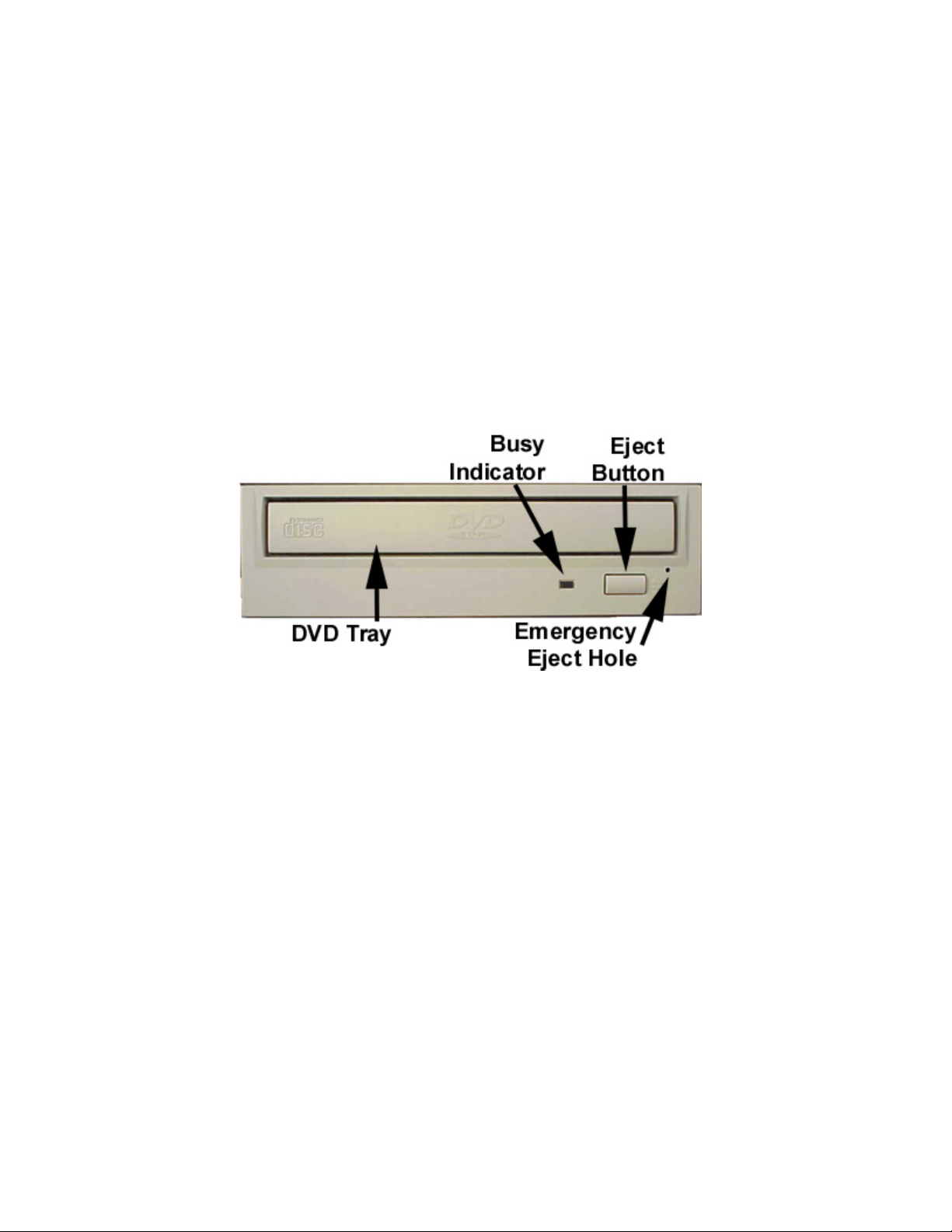
Front Panel
Figure 1.SD-M1802 DVD-ROM Drive Front Panel
Loading Tray
Busy Indicator
Eject
Button
Emergency
Eject Hole
Load disc using tray.
When you install a disc into the DVD-ROM drive, the BUSY light flashes slowly as it
attempts to locate the disc. One of the following will occur:
• BUSY light goes out. The DVD-ROM drive is ready to read data from the disc.
• BUSY light flashes slowly. The disc may be dirty.
• BUSY light remains ON. The DVD-ROM is accessing data.
• BUSY light remains ON indefinitely. The DVD-ROM is experiencing an error
The Eject button is used to open the disc tray so you can install or remove a disc.
The emergency eject hole is to be used only when the Loading Tray will not open when
Eject button is pressed.
SETUP – SD-M1802 DVD-ROM
The following steps must be performed to properly install your drive:
• Set Drive Jumper Settings
• Connect Audio Cable (optional)
• Attach IDE BUS Cable
• Attach Power Cable
• Mount Drive
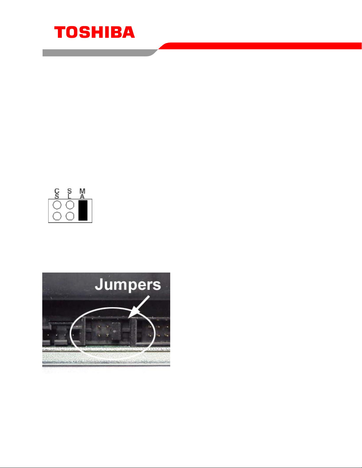
Jumper Settings
The mode select jumpers are 6 straight angle pins located on the rear of the DVD-ROM drive.
By placing a jumper on the pins, you can select the following functions:
CS
SL Configures drive as Slave
MA Configures drive as Master (default mode)
In most installations, jumper should remain in the MA position (factory default). It is recommended that
you install your DVD-ROM drive only on the secondary IDE BUS. If you are installing on primary IDE
BUS, your hard drive would then be the Master, and you should set your DVD-ROM drive to the Slave
position (SL)
Drive is configured using host interface signal CSEL
Figure 1.Mode Select Jumper
3
Figure 2.Jumper Locations
 Loading...