

Toshiba SD-M1302, SD-M1402 Installation Instructions Manual

SD-M1302 & SD-M1402 DVD-ROMs
with REALmagic Hollywood+ Playback Card
Installation Instructions
Congratulations on your purchase of a T oshiba SD-M1302 or SD-M1402
DVD-R OM drive and REALmagic Hollywood+ D VD/MPEG-2 Playback
Card Kit. The following information will help you in the simple installation of your new DVD-ROM. It is assumed that you are replacing a
presently installed CD-ROM with the enclosed DVD-ROM. If this is not
the case, additional installation hardware may be required. Refer to
REALmagic Hollywood+ User’s Guide for installation instructions on
the DVD/MPEG-2 Playback Card.
CHECKING YOUR KIT PACKAGING
Please unpack your DVD kit, and assure that you hav e the following items:
l T oshiba SD-M1302 or SD-M1402 AT API D VD-ROM dri ve
l DVD/MPEG-2 PCI Pla yback Card (compatible with all graphics cards)
l 13” 3.5mm ext. audio cable
l 14” HDB15 - 9 DIN overlay cable
l S-Video to RCA video converter cable
l REALmagic™ Accessory Kit en v elope
(with software, demo CD and Playback Card User’ s Guide)
l SD-M1302 & SD-M1402 DVD-R OM Installation Instructions
(this manual)
Additional items you may need that are not included in the kit are:
l Screwdriver
l mounting screws and mounting hardware
l IDE BUS cable
l DVD/CD-ROM Sound Cable
SYSTEM REQUIREMENT
The DVD-ROM kit requires the following:
✔ 2MB of free hard disk space
✔ 16MB of RAM
✔ Pentium-based PC (or compatible), 133MHz or higher
✔ PCI 2.1 compliant expansion slot
✔ VGA Card
✔ Plug and Play BIOS support
✔ Microsoft™ Windows 95 or higher
✔ Amplified stereo speakers
TOSHIBA
The following steps must be performed to properly install your DVDROM.
l Set DVD-ROM Drive Jumper Settings
l Connect Audio Cable
l Attach IDE BUS cable
l Mount DVD-ROM
SETTING JUMPERS
C
S
S
L
M
A
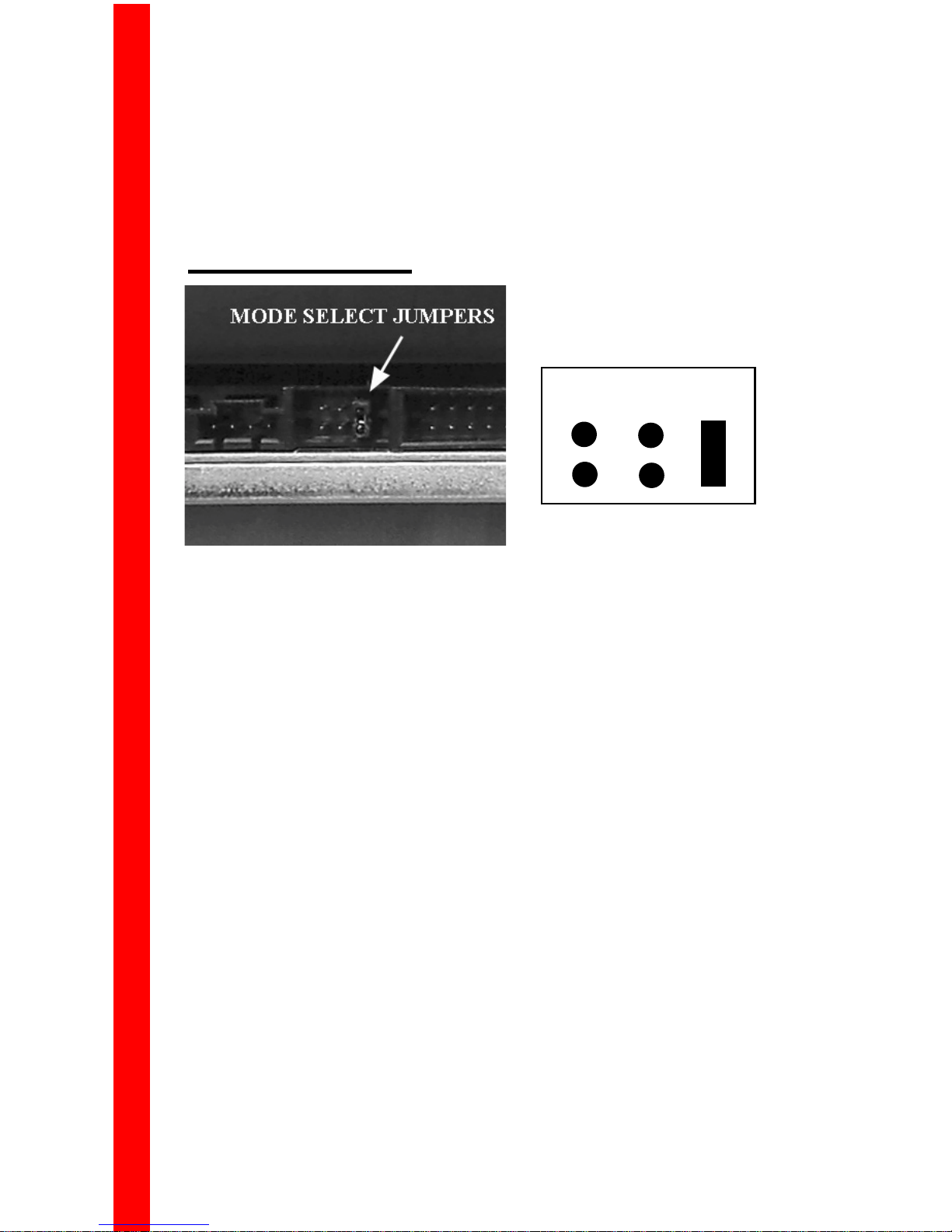
The mode select jumpers are 6 straight angle pins located on the rear of
the DVD-ROM. By placing a jumper on the pins, you can select the
following functions:
CS: – Drive is configured using host interface signal CSEL
SL: – Configures drive as Slave
MA: – Configures drive as Master (default mode)
In most installations, jumper should remain in MA position (factory default). It is recommended that you install your DVD-ROM only on the
secondary IDE BUS. If you are installing on primary IDE BUS, your
hard drive would then be the Master, and you should set your DVDROM to the Slave position (SL).
2
 Loading...