

Toshiba SD-M1212 - DVD-ROM Drive - IDE Specifications

DISK PRODUCTS
SD-M1212
DVD-ROM DRIVE
PRODUCT SPECIFICA TION
MARCH 1999
REV. 1.0
Specifications are subject to change without notice
DOCUMENT NUMBER
1 1899

SD-M1212 Rev.1.0
Notice
1.This product has no over-current protection circuit.
System should have appropriate over-current protection.
Toshiba Corporation makes no warranty of damages caused by no over-current protection.
2.This has a little possibility of errors.
To prevent damages and injury caused by the above, careful consideration for the safety and integrity
should be taken in the system design.
Do not use this product in a system that may cause hazard to human being or material loss caused by
the failure, loss of data and/or errors of this product.
3.Do not disassemble or modify this product.
Or, reliability, safety and performance can not be guaranteed.
4.Turn off the system power before mounting/removing this product.
Or, it may cause failure or damage.
5.Because the DC power socket of this product allows insertion of only one side direction, ascertain
direction carefully to insert the plug.
6.To build this product in an equipment, handle it only in electrostatically safe environment.
Do not touch connecting terminals directly.
Or, the product may be damaged by electrostatic energy.
7. This product can playback discs based on the formats described in item 3.1.(1). Do not load a disc
which is not conformed with those formats such as a shaped disc or a disc with its weight unbalanced
excessively.
A very high speed rotation is carried out inside the product, so abnormal vibration and malfunction may
occur if disc described above is loaded.
8. When a disc cannot be ejected because of some troubles, etc., turn off the power for the unit and eject
the disc using the emergency eject mechanism after passing more than 1 minute.
When the emergency eject is carried out while the power is on or immediately after the power off, the disc
may be eject in a rotating status. We do not assure if the disc is damaged by this.
9. When you close the tray, power must not be turned off. If the tray is pushed in with the hand during
power off, a breakdown may occur because the mechanism in the product is not in the transit
state during power off.
10. This product comes under the regulations of TWA (The Wassenaar Arrangement on Export Controls
for Conventional Arms and Dual Use Goods and Technologies).
When exporting the product, an export permission according to the regulations of your country will
be required.
SD-M1212 Rev.1.0
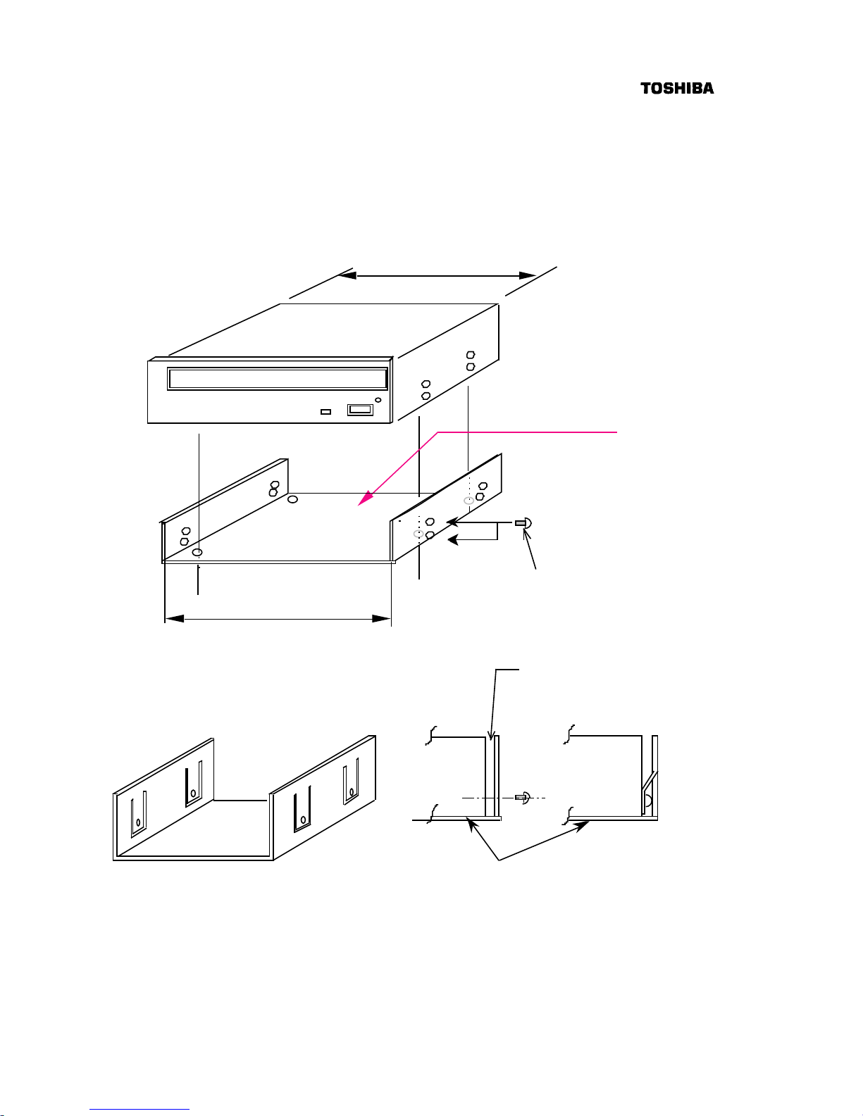
11. As for mounting bracket to incorporate this product into an equipment,
(1) When this product is incorporated into an equipment by using the mounting screw holes in the right
and left side planes, the clearance between this product and the mounting bracket is too wide;
(2) When this product is incorporated into an equipment by using the mounting screw hole in the
bottom, the surface of the mounting bracket is contorted.
If you use such mounting bracket as the above, this product will become deformed, which may cause
operation failure. Therefore, it is necessary to take account of the mounting bracket which has the
tolerances shown in Fig.1 or whose structure cannot cause this product to deform, as shown in Fig.2
146+/-0.3
146.3
+ 0.2
- 0
less than plane 0.5
Select screws, the length of which
threaded
onto the product is within 3 +/- 0.5 mm
Fig.1
this product
this product
before the fixing
after the fixing
mounting bracket
When a large amount space is left,
insert spacers, etc. to adjust the space
less than 0.5 mm between the product
and mounting bracket.
Fig.2

SD-M1212 Rev.1.0
Contents
1. Introduction ---------------------------------------------------------------------------------------------------------------------- 1
2. Features -------------------------------------------------------------------------------------------------------------------------- 3
3. Specifications ------------------------------------------------------------------------------------------------------------------ 4
3.1. Performance ------------------------------------------------------------------------------------------------------------ 4
3.2. Environmental Conditions ---------------------------------------------------------------------------------------- 6
3.2.1. Temperature and Humidity ---------------------------------------------------------------------------------- 6
3.2.2. Dust and Dirt ------------------------------------------------------------------------------------------------------ 6
3.2.3. Vibration ----------------------------------------------------------------------------------------------------------- 6
3.2.4. Atmospheric Pressure and Altitude -------------------------------------------------------------------- 6
3.2.5. Shock --------------------------------------------------------------------------------------------------------------- 6
3.3. Installation Conditions --------------------------------------------------------------------------------------------- 7
3.4. Dimensions and Mass --------------------------------------------------------------------------------------------- 7
3.5. Reliabilities ------------------------------------------------------------------------------------------------------------- 9
3.5.1. Error Rate ---------------------------------------------------------------------------------------------------------- 9
3.5.2. MTBF ---------------------------------------------------------------------------------------------------------------- 9
3.5.3. MTTR ---------------------------------------------------------------------------------------------------------------- 9
3.5.4. Drive Life ----------------------------------------------------------------------------------------------------------- 9
4. Configurations ----------------------------------------------------------------------------------------------------------------- 9
4.1. Electrical Circuits ------------------------------------------------------------------------------------------------------ 9
4.2. Optical Pickup --------------------------------------------------------------------------------------------------------- 9
4.3. Spindle Motor ---------------------------------------------------------------------------------------------------------- 9
4.4. Feed Motor -------------------------------------------------------------------------------------------------------------- 9
4.5. Tray Load/Eject Motor ---------------------------------------------------------------------------------------------- 9
5. Functions ------------------------------------------------------------------------------------------------------------------------11
5.1. Disc Data Configurations ------------------------------------------------------------------------------------------11
5.1. 1. DVD-ROM Data Configurations ---------------------------------------------------------------------------11
5.1. 2.CD-ROM Data Configurations ------------------------------------------------------------------------------11
5.2. Power ON/OFF Timing --------------------------------------------------------------------------------------------12
6. Interfaces ------------------------------------------------------------------------------------------------------------------------12
6.1. I/O Cable ------------------------------------------------------------------------------------------------------------------12
6.2. Signal Summary -------------------------------------------------------------------------------------------------------13
6.2.1. Signal Specifications ---------------------------------------------------------------------------------------- 13
6.2.2. Timing of Host Interface (PIO) ---------------------------------------------------------------------------- 14
6.2.3. Timing of Host Interface (DMA Single) ---------------------------------------------------------------- 15
6.2.4. Timing of Host Interface (DMA Multi) ------------------------------------------------------------------- 16
6.2.5. Timing of Host Interface (Ultra DMA) ------------------------------------------------------------------- 17
6.3. Connector ------------------------------------------------------------------------------------------------------------- 18
6.4. Support Command List -------------------------------------------------------------------------------------------- 20
7. Power Requirements ----------------------------------------------------------------------------------------------------- 21
7.1. Source Voltage ------------------------------------------------------------------------------------------------------ 21
7.1.1. Spike -------------------------------------------------------------------------------------------------------------- 21
7.1.2. Ripple ----------------------------------------------------------------------------------------------------------- 21

SD-M1212 Rev.1.0
7.2. Current Drain -------------------------------------------------------------------------------------------------------21
7.2.1.Sleep -------------------- --------------------------------------------------------------------------------------- 21
7.2.2. Standby ---------------------------------------------------------------------------------------------------------- 21
7.2.3. Continuous Read ------------------------------------------------------------------------------------------ 21
7.2.4. Idle ------------------------------------------------------------------------------------------------------------------ 21
7.2.5. Average ----------------------------------------------------------------------------------------------------------- 21
7.2.6. Maximum --------------------------------------------------------------------------------------------------------- 21
7.2.7. Peak in executing Access --------------------------------------------------------------------------------- 21
8. CD Audio ------------------------------------------------------------------------------------------------------------------- 22
8.1. Analog Out -----------------------------------------------------------------------------------------------------------22
8.2. Digital Out ------------------------------------------------------------------------------------------------------------22
8.3. Connector ------------------------------------------------------------------------------------------------------------ 22
8.4. Audio Modes ------------------------------------------------------------------------------------------------------- 22
8.5. Headphones Output (Option) ------------------------------------------------------------------------------- 22
8.5.1. Connector ----------------------------------------------------------------------------------------------------- 22
9. Device Configuration Jumper ---------------------------------------------------------------------------------------- 23
9.1. Device configuration Jumper --------------------------------------------------------------------------------- 23
10.Busy Indicator ------------------------------------------------------------------------------------------------------------- 24
11. Connections ------------------------------------------------------------------------------------------------------------- 25
11.1. Power Supply Cable ------------------------------------------------------------------------------------------- 25
11.2. Interface Cable --------------------------------------------------------------------------------------------------- 25
11.3. Audio Cable ------------------------------------------------------------------------------------------------------ 25
12. Emergency Eject ------------------------------------------------------------------------------------------------------ 25
13. Safety Standards/Agency Approvals --------------------------------------------------------------------------- 26
14. Electrostatic Discharge ---------------------------------------------------------------------------------------------- 26
15. Accessories -------------------------------------------------------------------------------------------------------------- 26
16. Packaging ----------------------------------------------------------------------------------------------------------------- 26
17. CE Declaration of conformity -------------------------------------------------------------------------------------- 26

1/28 SD-M1212 Rev.1.0
1. Introduction
This document describes TOSHIBA's SD-M1212 DVD-ROM Drive.
This drive supports DVD CSS (Contents Scramble Systems) Disc.
This drive reads digital data stored on CD-ROM, DVD-ROM and CD audio discs.
DVD-ROM disc spec (DVD-ROM Book) defines 120 mm and 80 mm in diameter, single and dual layers
as recording layer structure and single and double sides as recording side.
Maximum storage capacities are 4.38 GBytes and 15.9 GBytes for single layer/single side and
dual layer/double side respectively. (1 GByte=2
30
Bytes)
Due to these high capacity and high data transfer rate of 1352 KBytes/sec, DVD-ROM discs are
capable to store high quality and long duration MPEG-2 moving picture data. (1 KByte=2
10
Byte)
This drive reads digital data stored on DVD-ROM discs at maximum 6 times faster rotaional speed.
This drive reads digital data stored on CD-ROM discs at maximun 32 times faster rotational speed.
This drive is a new generation drive with highest performance such as 110 ms(DVD)/85 ms(CD)
Access Time.
This drive offers long life and durability because the disc is read by a LASER, thereby eliminating
physical contact with the disc.
This drive supports SFF-8020i of ATAPI (ATA Packet Interface ) spec. and SFF-8090 Ver.2 (Fuji2) of DVD
Commands.
This drive shows a highest performance such as100,000 hour MTBF.
This drive can be used in a vertical position or horizontal position.
This drive adopts RPC-II for its "Standard Specification Model".
Refer to the precation of the next page for the RPC-II.

2/28 SD-M1212 Rev.1.0
Matters to be attended to:
This drive adopts RPC-II for its “Standard Specification Model”.
This DVD-ROM Drive adopts RPC-II, the Phase II System of RPC (Regional Playback Control) for “Standard
Specification Model”, on the basis of a contract with the CSS (Contents Scramble System) organization.
(All of our former DVD-ROM Drives adopted RPC-I, the Phase I System.)
The CSS rule requires that all the products not only DVD-ROM Drives but also PC systems installing
DVD-ROM Drives sold from Jan.1, 2000 need to support RPC-II described above.
To playback a DVD-Movie Software with the Regional Code specified by using a DVD-ROM Drive with RPC-II
adopted, either the hardware or software used as applications on PC system side is also required to meet
RPC-II.
Namely, in the status that a hardware or a software for a DVD-Movie Playback Application planned to use in a
PC does not support RPC-II, if the "RPC-II (Standard Specification) Drive" is used in combination, DVD-Movie
Softwares with the Regional Code specified (most of DVD-Movie Softwares currently available on the market)
cannot be reproduced. So, in such a case, "RPC-I Specifications Supported Model" must be purchased for a
while.
However, all the drive manufacturers must obey to the deadline specified by the CSS rule saying; all DVDROM Drives have to implement Phase II from Jan.1, 2000. So we recommend that you will change your DVDMovie Playback Hardware or Software to those applicable to the RPC-II as soon as possible and investigate to
combine your system with the RPC-II Specification Drives.
Since we determine the drives are of RPC-I or RPC-II when manufacturing at factory and ship, the
specification change after shipping is not available in principle. Especially, changing the RPC-II specification
drive to the RPC-I is prohibited by the CSS rule.
In the combination of the drive and PC system with RPC-II supported, as far as the Regional Code of a DVDMovie Software and the code memorized in the RPC-II Specification Drive coincides, the Movie Software is
allowed to carry out.
In the RPC-II Specification Drive, the region change by an end user is permitted up to 5 times in total
including the initial region set. After change to the fifth region is carried out, the Drive enters Parm State
(“no change allowed”status).
The drive with Parm State is permitted up to 4 times of "reinitialization" by a drive manufacturer or a specific
service center authorized by the CSS. Since it is considered that the reinitialization is carried out after the
completion of the region confirmation through test items in the PC manufacturer’s manufacturing line or the
completion of drive repair, etc., the number of reinitialization times may vary from 0 (no reinitialization
available) to 4 times. So, we recommend that not to disclose the reinitialization process to end users but only
to inform the number of region setting times as "end user’s direct region setting is available up to 5 times in
total."

4/28 SD-M1212 Rev.1.0
3. Specifications
3.1.Performance
(1) Applicable Disc *
1
DVD: DVD-ROM (DVD-5, DVD-9, DVD-10, DVD-18),
DVD-R (read)
CD : CD-DA, CD+(E)G, CD-MIDI, CD-TEXT, CD-ROM,
CD-ROM XA, CD-I, CD-I Bridge (Photo-CD, Video-CD)
Multisession CD (Phto-CD, CD-EXTRA, CD-R,
CD-RW), CD-R (read), CD-RW (read)
(2) Data Capacity
User Data/Block DVD-ROM: 2,048 Byte/Block
CD-ROM : 2,048 Byte/Block (Mode 1)
2,336 Byte/Block (Mode 2)
Data Cpacity/Disc: (1 GB=230Byte, 1 MB=220Byte, 1 KB=210Byte)
DVD- 5: 4.377 GB (4.700 Billion Byte)
DVD- 9: 7.959 GB (8.545 Billion Byte)
DVD-10: 8.754 GB (9.400 Billion Byte)
DVD-18: 15.917 GB (17.091 Billion Byte)
CD (Mode-1): 656.5 MB (688.4 Million Byte)
CD (Mode-2): 748.8 MB (785.2 Million Byte)
(3) Rotational Speed
DVD : Approx. 3,500 rpm (2.5-6X CAV)
DVD-R : Approx. 1,100-2,800 rpm (2X CLV)
CD : Approx. 6,900 rpm (13.8-32X CAV)
CD-RW: Approx. 4,300 rpm (8.6-20X CAV)
CD Audio,Video-CD: Approx. 1,200 - 2,000 rpm (4-5.7X PCAV)
(4) Transfer Rate
( 1 KByte=210Byte=1,024 Bytes, 1 Mbyte=220Byte=1,048,576 Bytes)
Sustained Block Transfer Rate DVD: 1,683-4,056 Block/s
CD : 1,034-2,400 Block/s
Sustained Data Transfer Rate DVD: 3,366-8,112 KByte/s
CD : Mode 1 2,069-4,800 KByte/s
Mode 2 2,360-5,475 KByte/s
Burst DataTransfer Rate 16.7 MByte/s (PIO Mode 4 )
8.3 MByte/s (Single word DMA transfer mode-2 )
16.7 MByte/s ( Multiple word DMA transfer mode-2)
33.3 MByte/s (Ultra DMA )

5/28 SD-M1212 Rev.1.0
(5) Access Time
Average Random Access Time DVD:*2110 ms Typ
CD:*385 ms Typ
Average Random Seek Time DVD:*490 ms Typ
CD:*580 ms Typ
Average Full Stroke Access Time DVD:*6210 ms Typ
CD:*7140 ms Typ
(6) Spin up Time ( Focus Search Time and Disc Motor Start up Time )
DVD: 1.4 s Typ
CD: 3.1 s Typ
(7) Data Buffer Capacity 256 KByte
*1: All disc written in CD or DVD formats, except CD-DA (audio), require additional specific
application software and/or hardware. This drive referred in the specification is capable of reading
these data formats. However, in order to run applications that use these formats you must first have the
required software and/or hardware.
*2: Measured by performing multiple accesses which means reads of data blocks over whole area of the
media from 0 (h) block to 1E7725(h) (4.089 Billion Byte:87 % of total area) block more than 3000
times. Includes positioning, setting, latency time and ECC implementation time (if required).
*3: Measured by performing multiple accesses which means reads of data blocks over whole area of the
media from 00 min 02 sec 00 Frame to 60 min 01 sec 74 Frame (552.96 Million Byte:87 %
of total area at linear velocity of 1.3 m/s) more than 3000 times. Includes positioning, setting, latency
time and ECC implementation time (if required).
*4: Measured by performing multiple seek which means seeks of data block over whole area of the media
from 0(h) block to 1E7725(h) block more than 3000 times.
Includes positioning, setting time which is same definition as HDD.
*5: Measured by performing multiple seek which means seeks of data block over whole area of the media
from 00 min 02 sec 00 Frame to 60 min 01 sec 74 Frame more than 3000 times. Includes positioning,
setting time which is same definition as HDD.
*6: Measured by performing maximum accesses which means reads of each data block of
0 (h) Frame and 1E7725(h) Frame alternately more than 100 times.
Includes positioning, setting, latency time and ECC implementation time (if required)
*7: Measured by performing maximum accesses which means reads of each data block of 00 min
02 sec 00 Frame and 60 min 01 sec 74 Frame alternately more than 100 times.
Includes positioning, setting, latency time and ECC implementation time (if required)
(8) Load/Eject (a) Electrical Load/Eject (Eject Button)
(b) Load/Eject by ATAPI command
(c) Emergency Eject
(9) Air Flow Not Required
(10) Acoustic Noise 45 dB (IEC 179 A weighted at 1 m)
(11) Power Supply +5 V , +12 V (details in Section 7)
 Loading...