

Page 1
SERVICE MANUAL
SD-34VLSL
VIDEO CASSETTE RECORDER
FILE NO. 810-200440
DVD PLAYER &
SD-34VESE
SD-34VBSB
SEP. 2004
Page 2

CONTENTS
SECTION 1 . . . . SUMMARY
SECTION 2 . . . . CABINET & MAIN CHASSIS
SECTION 3 . . . . ELECTRICAL
SECTION 4 . . . . MECHANISM OF VCR PART
SECTION 5 . . . . MECHANISM OF DVD PART
SECTION 6 . . . . REPLACEMENT PARTS LIST
Page 3

1-2
SECTION 1
SUMMARY
CONTENTS
PRODUCT SAFETY SERVICING GUIDELINES FOR VIDEO PRODUCTS .......... 1-2
SERVICING PRECAUTIONS .................................................................................. 1-3
SERVICE INFORMATION FOR EEPROM IC SETTING ........................................ 1-4
OWNER’S MANUAL ............................................................................................... 1-6
Page 4

1-3
CAUTION : DO NOT ATTEMPT TO MODIFY THIS PRODUCT IN ANY WAY,
NEVER PERFORM CUSTOMIZED INSTALLATIONS WITHOUT MANUFACTURER’S APPROVAL. UNAUTHORIZED MODIFICATIONS WILL NOT ONLY
VOID THE WARRANTY, BUT MAY LEAD TO YOUR BEING LIABLE FOR ANY
RESULTING PROPERTY DAMAGE OR USER INJURY.
SERVICE WORK SHOULD BE PERFORMED ONLY AFTER YOU ARE THOROUGHLY FAMILIAR WITH ALL OF THE FOLLOWING SAFETY CHECKS
AND SERVICING GUIDELINES. TO DO OTHERWISE, INCREASES THE
RISK OF POTENTIAL HAZARDS AND INJURY TO THE USER.
WHILE SERVICING, USE AN ISOLATION TRANSFORMER FOR PROTECTION FROM A.C. LINE SHOCK.
SAFETY CHECKS
AFTER THE ORIGINAL SERVICE PROBLEM HAS BEEN CORRECTED. A
CHECK SHOULD BE MADE OF THE FOLLOWING.
SUBJECT : FIRE & SHOCK HAZARD
1. BE SURE THAT ALL COMPONENTS ARE POSITIONED IN SUCH A WAY
AS TO AVOID POSSIBILITY OF ADJACENT COMPONENT SHORTS.
THIS IS ESPECIALLY IMPORTANT ON THOSE MODULES WHICH ARE
TRANSPORTED TO AND FROM THE REPAIR SHOP.
2. NEVER RELEASE A REPAIR UNLESS ALL PROTECTIVE DEVICES
SUCH AS INSULATORS, BARRIERS, COVERS, SHIELDS, STRAIN
RELIEFS, POWER SUPPLY CORDS, AND OTHER HARDWARE HAVE
BEEN REINSTALLED PER ORIGINAL DESIGN. BE SURE THAT THE
SAFETY PURPOSE OF THE POLARIZED LINE PLUG HAS NOT BEEN
DEFEATED.
3. SOLDERING MUST BE INSPECTED TO DISCOVER POSSIBLE COLD
SOLDER JOINTS, SOLDER SPLASHES OR SHARP SOLDER POINTS.
BE CERTAIN TO REMOVE ALL LOOSE FOREIGN PARTICLES.
4. CHECK FOR PHYSICAL EVIDENCE OF DAMAGE OR DETERIORATION
TO PARTS AND COMPONENTS. FOR FRAYED LEADS, DAMAGED
INSULATION (INCLUDING A.C. CORD). AND REPLACE IF NECESSARY
FOLLOW ORIGINAL LAYOUT, LEAD LENGTH AND DRESS.
5. NO LEAD OR COMPONENT SHOULD TOUCH A RECIVING TUBE OR
A RESISTOR RATED AT 1 WATT OR MORE. LEAD TENSION AROUND
PROTRUNING METAL SURFACES MUST BE AVOIDED.
6. ALL CRITICAL COMPONENTS SUCH AS FUSES, FLAMEPROOF
RESISTORS, CAPACITORS, ETC. MUST BE REPLACED WITH EXACT
FACTORY TYPES, DO NOT USE REPLACEMENT COMPONENTS
OTHER THAN THOSE SPECIFIED OR MAKE UNRECOMMENDED CIRCUIT MODIFICATIONS.
7. AFTER RE-ASSEMBLY OF THE SET ALWAYS PERFORM AN A.C.
LEAKAGE TEST ON ALL EXPOSED METALLIC PARTS OF THE CABINET, (THE CHANNEL SELECTOR KNOB, ANTENNA TERMINALS. HANDLE AND SCREWS) TO BE SURE THE SET IS SAFE TO OPERATE
WITHOUT DANGER OF ELECTRICAL SHOCK. DO NOT USE A LINE
ISOLATION TRANSFORMER DURING THIS TEST USE AN A.C. VOLTMETER, HAVING 5000 OHMS PER VOLT OR MORE SENSITIVITY, IN
THE FOLLOWING MANNER; CONNECT A 1500 OHM 10 WATT RESISTOR, PARALLELED BY A .15 MFD. 150.V A.C TYPE CAPACITOR
BETWEEN A KNOWN GOOD EARTH GROUND (WATER PIPE, CONDUIT, ETC.) AND THE EXPOSED METALLIC PARTS, ONE AT A TIME.
MEASURE THE A.C. VOLTAGE ACROSS THE COMBINATION OF 1500
OHM RESISTOR AND .15 MFD CAPACITOR. REVERSE THE A.C. PLUG
AND REPEAT A.C. VOLTAGE MEASUREMENTS FOR EACH EXPOSED
METALLIC PART. VOLTAGE MEASURED MUST NOT EXCEED 75
VOLTS R.M.S. THIS CORRESPONDS TO 0.5 MILLIAMP A.C ANY
VALUE EXCEEDING THIS LIMIT CONSTITUTES A POTENTIAL SHOCK
HAZARD AND MUST BE CORRECTED IMMEDIATELY.
SUBJECT: GRAPHIC SYMBOLS
THE LIGHTNING FLASH WITH APROWHEAD SYMBOL. WITHIN
AN EQUILATERAL TRIANGLE, IS INTENDED TO ALERT THE
SERVICE PERSONNEL TO THE PRESENCE OF UNINSULATED
“DANGEROUS VOLTAGE” THAT MAY BE OF SUFFICIENT MAGNI-
TUDE TO CONSTITUTE A RISK OF ELECTRIC SHOCK.
THE EXCLAMATION POINT WITHIN AN EQUILATERAL TRIANGLE IS INTENDED TO ALERT THE SERVICE PERSONNEL TO
THE PRESENCE OF IMPORTANT SAFETY INFORMATION IN
SERVICE LITERATURE.
SUBJECT : X-RADIATION
1. BE SURE PROCEDURES AND INSTRUCTIONS TO ALL SERVICE PERSONNEL COVER THE SUBJECT OF X-RADIATION. THE ONLY POTENTIAL SOURCE OF X-RAYS IN CURRENT T.V. RECEIVERS IS THE PICTURE TUBE. HOWEVER, THIS TUBE DOES NOT EMIT X-RAYS WHEN
THE HIGH VOLTAGE IS AT THE FACTORY SPECIFIED LEVEL. THE
PROPER VALUE IS GIVEN IN THE APPLICABLE SCHEMATIC. OPERATION AT HIGHER VOLTAGES MAY CAUSE A FAILURE OF THE PICTURE TUBE OR HIGH VOLTAGE SUPPLY AND, UNDER CERTAIN CIRCUMSTANCES, MAY PRODUCE RADIATION IN EXCESS OF DESIRABLE LEVELS.
2. ONLY FACTORY SPECIFIED C.R.T. ANODE CONNECTORS MUST BE
USED. DEGAUSSING SHIELDS ALSO SERVE AS X-RAY SHIELD IN
COLOR SETS, ALWAYS RE-INSTALL THEM.
3. IT IS ESSNTIAL THAT SERVICE PERSONNEL HAVE AVAILABLE AN
ACCURATE AND RELIABLE HIGH VOLTAGE METER. THE CALIBRA
TION OF THE METER SHOULD BE CHECKED PERIODICALLY
AGAINST A REFERENCE STANDARD, SUCH AS THE ONE AVAILABLE
AT YOUR DISTRIBUTOR.
4. WHEN THE HIGH VOLTAGE CIRCUITRY IS OPERATING PROPERLY
THERE IS NO POSSIBILITY OF AN X-RADIATION PROBLEM. EVERY
TIME A COLOR CHASSIS IS SERVICED. THE BRIGHTNESS SHOULD
BE RUN UP AND DOWN WHILE MONITORING THE HIGH VOLTAGE
WITH A METER TO BE CERTAIN THAT THE HIGH VOLTAGE DOES
NOT EXCEED THE SPECIFIED VALUE AND THAT IT IS REGULATING
CORRECTLY, WE SUGGEST THAT YOU AND YOUR SERVICE ORGANIZATION REVIEW TEST PROCEDURES SO THAT VOLTAGE REGULATION IS ALWAYS CHECKED AS A STANDARD SERVICING PROCEDURE. AND THAT THE HIGH VOLTAGE READING BE RECORDER ON
EACH CUSTOMER’S INVOICE.
5. WHEN TROUBLESHOOTING AND MAKING TEST MEASUREMENTS IN
A PRODUCT WITH A PROBLEM OF EXCESSIVE HIGH VOLTAGE,
AVOID BEING UNNECESSARILY CLOSE TO THE PICTURE TUBE AND
THE HIGH VOLTAGE SUPPLY. DO NOT OPERATE THE PRODUCT
LONGER THAN IS NECESSARY TO LOCATE THE CAUSE OF EXCES
SIVE VOLTAGE.
6. REFER TO HV. B+ AND SHUTDOWN ADJUSTMENT PROCEDURES
DESCRIBED IN THE APPROPRIATE SCHEMATIC AND DIAGRAMS
(WHERE USED).
SUBJECT: IMPLOSION
1. ALL DIRECT VIEWED PICTURE TUBES ARE EQUIPPED WITH AN INTE
GRAL IMPLOSION PROTECTION SYSTEM, BUT CARE SHOULD BE
TAKEN TO AVOID DAMAGE DURING INSTALLATION, AVOID
SCRATCHING THE TUBE. IF SCRATCHED REPLACE IT.
2. USE ONLY RECOMMENDED FACTORY REPLACEMENT TUBES.
SUBJECT : TIPS ON PROPER INSTALLATION
1. NEVER INSTALL ANY PRODUCT IN A CLOSED-IN RECESS, CUBBYHOLE OR CLOSELY FITTING SHELF SPACE. OVER OR CLOSE TO
HEAT DUCT, OR IN THE PATH OF HEATED AIR FLOW.
2. AVOID CONDITIONS OF HIGH HUMIDITY SUCH AS: OUTDOOR PATIO
INSTALLATIONS WHERE DEW IS A FACTOR, NEAR STEAM RADIATORS WHERE STEAM LEAKAGE IS A FACTOR, ETC.
3. AVOID PALCEMENT WHERE DRAPERIES MAY OBSTRUCT REAR
VENTING. THE CUSTOMER SHOULD ALSO AVOID THE USE OF DECORATIVE SCARVES OR OTHER COVERINGS WHICH MIGHT
OBSTRUCT VENTILATION.
4. WALL AND SHELF MOUNTED INSTALLATIONS USING A COMMERCIAL MOUNTING KIT. MUST FOLLOW THE FACTORY APPROVED
MOUNTING INSTRUCTIONS A PRODUCT MOUNTED TO A SHELF OR
PLATFORM MUST RETAIN ITS ORIGINAL FEET (OR THE EQUIVALENT
THICKNESS IN SPACERS) TO PROVIDE ADEQUATE AIR FLOW
ACROSS THE BOTTOM, BOLTS OR SCREWS USED FOR FASTENERS
MUST NOT TOUCH ANY PARTS OR WIRING. PERFORM LEAKAGE
TEST ON CUSTOMIZED INSTALLATIONS.
5. CAUTION CUSTOMERS AGAINST THE MOUNTING OF A PRODUCT ON
SLOPING SHELF OR A TILTED POSITION, UNLESS THE PRODUCT IS
PROPERLY SECURED.
6. A PRODUCT ON A ROLL-ABOUT CART SHOULD BE STABLE ON ITS
MOUNTING TO THE CART. CAUTION THE CUSTOMER ON THE HAZARDS OF TRYING TO ROLL A CART WITH SMALL CASTERS ACROSS
THRESHOLDS OR DEEP PILE CARPETS.
7. CAUTION CUSTOMERS AGAINST THE USE OF A CART OR STAND
WHICH HAS NOT BEEN LISTED BY UNDERWRITERS LABORATORIES,
INC. FOR USE WITH THEIR SPECIFIC MODEL OF TELEVISION
RECEIVER OR GENERICALLY APPROVED FOR USE WITH T.V.’S OF
THE SAME OR LARGER SCREEN SIZE.
8. CAUTION CUSTOMERS AGAINST THE USE OF EXTENSION CORDS,
EXPLAIN THAT A FOREST OF EXTENSIONS SPROUTING FROM A SINGLE OUTLET CAN LEAD TO DISASTROUS CONSEQUENCES TO
HOME AND FAMILY.
PRODUCT SAFETY SERVICING GUIDELINES FOR VIDEO PRODUCTS
A.C. VOLTMETER
GOOD EARTH GROUND
SUCH AS THE WATER
PIPE. CONDUIT. ETC
PLACE THIS PROBE
ON EACH EXPOSED
METAL PART
Page 5

1-4
SERVICING PRECAUTIONS
CAUTION : Before servicing the VCR+DVD covered by this
service data and its supplements and addends, read and follow the
SAFETY PRECAUTIONS. NOTE : if unforeseen circumstances create conflict between the following servicing
precautions and any of the safety precautions in this publications, always follow the safety precautions.
Remembers Safety First:
General Servicing Precautions
1. Always unplug the VCR+DVD AC power cord from the AC
power source before:
(1) Removing or reinstalling any component, circuit board,
module, or any other assembly.
(2) Disconnection or reconnecting any internal electrical
plug or other electrical connection.
(3) Connecting a test substitute in parallel with an elec-
trolytic capacitor.
Caution : A wrong part substitution or incorrect
polarity installation of electrolytic capacitors may result
in an explosion hazard.
2. Do not spray chemicals on or near this VCR+DVD or any
of its assemblies.
3. Unless specified otherwise in this service data, clean
electrical contacts by applying an appropriate contact
cleaning solution to the contacts with a pipe cleaner,
cotton-tipped swab, or comparable soft applicator.
Unless specified otherwise in this service data, lubrication
of contacts is not required.
4. Do not defeat any plug/socket B+ voltage interlocks with
whitch instruments covered by this service manual might
be equipped.
5. Do not apply AC power to this VCR+DVD and/or any of its
electrical assemblies unless all solid-state device heat
sinks are cerrectly installed.
6. Always connect test instrument ground lead to the
appropriate ground before connection the test instrument
positive lead. Always remove the test instrument ground
lead last.
Insulation Checking Procedure
Disconnect the attachment plug from the AC outlet and turn
the power on. Connect an insulation resistance meter(500V)
to the blades of the attachment plug. The insulation resistance between each blade of the attachment plug and accessible conductive parts (Note 1) should be more than 1Mohm.
Note 1 : Accessible Conductive Parts including Metal panels,
Input terminals, Earphone jacks, etc.
Electrostatically Sensitive (ES) Devices
Some semiconductor (solid state) devices can be damaged
easily by static electricity. Such components commonly are
called Electrostatically Sensitive (ES) Devices. Examples of
typical ES devices are integrated circuits and some field
effect transistors and semiconductor chip components.
The following techniques should be used to help reduce the
incidence of component damage caused by static electricity.
1. Immediately before handling any semiconductor component or semiconductor-equipped assembly, drain off any
electrostatic charge on your body by touching a known
earth ground. Alternatively, obtain and wear a commercially available discharging wrist strap device, which
should be removed for potential shock reasons prior to
applying power to the unit under test.
2. After removing an electrical assembly equipped with ES
devices, place the assembly on a conductive surface such
as aluminum foil, to prevent electrostatic charge buildup or
exposure of the assembly.
3. Use only a grouned-tip soldering iron to solder or unsolder
ES devices.
4. Use only an anti-static solder removal device. Some
solder removal devices not classified a “anti-static” can
generate electrical charges sufficient to damage ES
devices.
5. Do not use freon-propelled chemicals. These can
generate electrical charge sufficient to damage ES
devices.
6. Do not remove a replacement ES device from its protec
tive package until immediately before you are ready to
install it. (Most replacement ES devices are packaged with
leads electrically shorted together by conductive foam,
aluminum foil, or comparable conductive material).
7. Immediately before removing the protective material from
the leads of a replacement ES device, touch the protective
material to the chassis or circuit assembly into which the
device will be installed.
Caution : Be sure no power is applied to the chassis or
circuit, and observe all other safety precautions.
8. Minimize bodily motions when handling unpackaged
replacement ES devices. (Normally harmless motion such
as the brushing together of your clothes fabric or the lifting
of your foot from a carpeted floor can generate static electricity sufficient to damage an ES device.)
Page 6
1-5
SERVICE INFORMATION FOR EEPROM IC SETTING
MODEL NAME HEX BINARY
SD-34VLSL OPT1 FC 00000000
OPT2 C3 00000000
OPT3 5A 00000000
OPT4 21 00000000
OPT5 00 00000000
SD-34VBSB OPT1 FE 00000000
OPT2 CD 00000000
OPT3 4A 00000000
OPT4 02 00000000
OPT5 00 00000000
SD-34VESE OPT1 FC 00000000
OPT2 D6 00000000
OPT3 7A 00000000
OPT4 00 00000000
OPT5 00 00000000
WR : OK I : EXIT MOVE :
F G
EDIT : DE
1. DETECT NEW EEPROM (OPTION EDIT
SCREEN)
- Eeprom EDIT screen automatically appears if
replacing Eeprom.
- Setup option data using the cursor Up/Down key
of a remote control.
(Setup upon BOM depending on OPT1~OPT5
model)
• Since an initial remote control is set to LG for LG
model, appropriately set optiona data using the
cursor Up/Down key.
2. EEPROM WRITED COMPLETE SCREEN
- Writes data on EEPROM by using REMOCON
"OK".
- If completing the option data screen with a menu
key, Powering Off is automatically done and the
option edit screen is arranged.
3. PG ADJUST
1) Payback the SP standard tape
2) Press the “1” key on the Remote controller and
the “PLAY” key on the Front Panel the same
time, then it goes in to Tracking initial mode.
3) Repeat the above step(No.2), then it finishes
the PG adjusting automatically.
4) Stop the playback, then it goes out to PG
adjusting mode after mony the PG data.
4. EEPROM INITIAL
- SETUP is displayed in the field if pressing the
FRONT REC KEY with the remocon number
"CLEAR" key pressed in the status of powering
Off.
- AUTO SEARCH is done since the initial screen of
ACMS is serviced if powering On.
- Check basic operation (PLAY/RECORD...)
EEPROM option code No. setting EEPROM option code No. setting procedure
NAME HEX BINARY
OPT1 00 00000000
OPT2 00 00000000
OPT3 00 00000000
OPT4 00 00000000
OPT5 00 00000000
WR : OK I : EXIT MOVE : F G
EDIT : DE
MASKROM : R00
EEPROM : R13 LG CODE
C/SUM : OF
Page 7

SD-34VLSL
OWNER’S MANUAL
DVD PLAYER &
VIDEO CASSETTE RECORDER
Before connecting, operating or adjusting this product,
please read this instruction booklet carefully and completely.
©2004 Toshiba Corporation
This device does not tape-record copy protected DVD Video Discs.
R
Page 8

1-7
Warning:To reduce the risk of electric
shock, do not remove the cover or back
of this product.There are no user-serviceable parts inside. Refer servicing to
qualified service personnel.
Warning:To reduce the risk of fire or
electric shock, do not expose this product to dripping or splashing water, rain,
or moisture. Do not place objects filled
with water such as vases, on the product.
Warning:This digital video disc player
employs a laser system. Use of controls,
adjustments, or the performance of procedures other than those specified herein may result in hazardous radiation
exposure.
Warning:To prevent direct exposure to
laser beam, do not open the enclosure.
Visible laser radiation may be present
when the enclosure in opened.
Warning: Never stare directly into the
laser beam.
Caution: Do not install this product in a
confined space such as a book case or
similar unit.
This product is manufactured to comply
with the radio interference requirements
of EEC DIRECTIVE 89/336/EEC,
93/68/EEC and 73/23/EEC.
Notes on Copyrights:
It is forbidden by law to copy, broadcast, show, broadcast via cable, play in public, or rent copyrighted
material without permission. This product features the
copy protection function developed by Macrovision.
Copy protection signals are recorded on some discs.
When recording and playing the pictures of these
discs picture noise will appear. This product incorporates copyright protection technology that is protected
by method claims of certain U.S. patents and other
intellectual property rights owned by Macrovision
Corporation and other rights owners. Use of this
copyright protection technology must be authorized
by Macrovision Corporation, and is intended for home
and other limited viewing uses only unless otherwise
authorized by Macrovision Corporation. Reverse engineering or disassembly is prohibited.
CONSUMERS SHOULD NOTE THAT NOT ALL
HIGH DEFINITION TELEVISION SETS ARE FULLY
COMPATIBLE WITH THIS PRODUCT AND MAY
CAUSE ARTIFACTS TO BE DISPLAYED IN THE
PICTURE. IN CASE OF 525 OR 625 PROGRESSIVE
SCAN PICTURE PROBLEMS, IT IS ECOMMENDED
THAT THE USER SWITCH THE CONNECTION TO
THE ‘STANDARD DEFINITION’ OUTPUT. IF THERE
ARE QUESTIONS REGARDING OUR TV SET COMPATIBILITY WITH THIS MODEL 525p AND 625p
DVD PLAYER, PLEASE CONTACT OUR CUSTOMER SERVICE CENTER.
SERIAL NUMBER:
You can find the serial number on the back of the
unit. This number is unique to this unit and not available to others.You should record requested information here and retain this guide as a permanent record
of your purchase.
Model No. ______________________________
Serial No. ______________________________
Date of Purchase_________________________
CAUTION
RISK OF ELECTRIC SHOCK
DO NOT OPEN
Page 9

1-8
SOME DOS AND DON'TS ON THE SAFE USE OF EQUIPMENT
This equipment has been designed and manufactured to meet international safety standards but,
like any electrical equipment, care must be taken if you are to obtain the best results and safety is to
be assured. So, please read the points below for your own safety. They are of a general nature,
intended to help you with all your electronic consumer products and some points may not apply to
the goods you have just purchased.
**************
DO read the operating instructions before you attempt to use the equipment.
DO ensure that all electrical connections (including the mains plug, extension leads and inter- con-
nections between the pieces of equipment) are properly made and in accordance with the manufacturer's instructions. Switch off and withdraw the mains plug before making or changing connections.
DO consult your dealer if you are ever in doubt about the installation, operation or safety of your
equipment.
DO be careful with glass panels or doors on equipment
**************
DON'T remove any fixed cover as this may expose dangerous voltages.
DON'T obstruct the ventilation openings of the equipment with items such as newspapers, table-
cloths, curtains, etc. Overheating will cause damage and shorten the life of the equipment.
DON'T allow electrical equipment to be exposed to dripping or splashing, or objects filled with liquids, such as vases, to be placed on the equipment.
DON'T place hot objects or naked flame sources such as lighted candles or nightlights on, or close
to equipment. High temperatures can melt plastic and lead to fires.
DON'T use makeshift stands and NEVER fix legs with wood screws - to ensure complete safety
always fit the manufacturer's approved stand or legs with the fixings provided according to the
instructions.
DON'T use equipment such as personal stereos or radios so that you are distracted from the
requirements of traffic safety. It is illegal to watch television whilst driving.
DON'T listen to headphones at high volume, as such use can permanently damage your hearing.
DON'T leave equipment switched on when it is unattended unless it is specifically stated that it is
designed for unattended operation or has a stand-by mode. Switch off using the switch on the
equipment and make sure that your family know how to do this. Special arrangements may need to
be made for infirm or handicapped people.
DON'T continue to operate the equipment if you are in any doubt about it working normally, or if it is
damaged in any way -switch off, withdraw the mains plug and consult your dealer.
ABOVE ALL
---NEVER let anyone especially children push anything into holes, slots or any other opening
in the case - this could result in a fatal electrical shock;
---NEVER guess or take chances with electrical equipment of any kind
---it is better to be safe than sorry!
*************
Page 10

1-9
Contents
Introduction . . . . . . . . . . . . . . . . . . . . . . . . . .5
Symbol Used in this Manual . . . . . . . . . . . . . . . . . .5
About the Symbol Display . . . . . . . . . . . . . . . . .5
Notes on Discs . . . . . . . . . . . . . . . . . . . . . . . . . . . . .5
Handling Discs . . . . . . . . . . . . . . . . . . . . . . . . . . .5
Storing Discs . . . . . . . . . . . . . . . . . . . . . . . . . . . .5
Cleaning Discs . . . . . . . . . . . . . . . . . . . . . . . . . . .5
Moisture Condensation . . . . . . . . . . . . . . . . . . . .5
Types of Playable Discs . . . . . . . . . . . . . . . . . . . . . .6
Regional code . . . . . . . . . . . . . . . . . . . . . . . . . . . . .6
Selecting the Viewing Source . . . . . . . . . . . . . . . . .6
Disc-related terms . . . . . . . . . . . . . . . . . . . . . . . . . .7
Front Panel . . . . . . . . . . . . . . . . . . . . . . . . . . . . . . . .8
Display Window . . . . . . . . . . . . . . . . . . . . . . . . . . . . .9
Remote Control . . . . . . . . . . . . . . . . . . . . . . . . .10-11
Rear Panel . . . . . . . . . . . . . . . . . . . . . . . . . . . . . . . .12
Preparation . . . . . . . . . . . . . . . . . . . . . . . . .13
Connecting to a TV and Decoder (or Set Top Box)
. .13
Connecting to Optional Equipment . . . . . . . . . . . .14
Tuning in a video channel on your TV . . . . . . . . . .15
Using your DVD+VCR for the very first time . . . . .15
Setting the clock Manually . . . . . . . . . . . . . . . . . . .16
To set the colour system . . . . . . . . . . . . . . . . . . . .16
To set the RF OUT sound system . . . . . . . . . . . . .16
How to use the main menu . . . . . . . . . . . . . . . . . .17
Tuning in TV Stations Automatically . . . . . . . . . . . .17
Tuning in TV Stations Manually . . . . . . . . . . . . . . .18
Changing the order of TV Stations . . . . . . . . . . . . .19
Deleting TV Stations . . . . . . . . . . . . . . . . . . . . . . . .19
DVD On-Screen Display . . . . . . . . . . . . . . . . . . . . .20
Initial Settings . . . . . . . . . . . . . . . . . . . . . . . . . . . .21
General Operation . . . . . . . . . . . . . . . . . . . . . . .21
LANGUAGE . . . . . . . . . . . . . . . . . . . . . . . . . . . .21
• Menu Language . . . . . . . . . . . . . . . . . . . . . . . .21
• Disc Audio / Subtitle / Menu . . . . . . . . . . . . . .21
DISPLAY . . . . . . . . . . . . . . . . . . . . . . . . . . . . . . .21
• TV Aspect . . . . . . . . . . . . . . . . . . . . . . . . . . . .21
• Display Mode . . . . . . . . . . . . . . . . . . . . . . . . . .21
• Progressive Scan . . . . . . . . . . . . . . . . . . . .21-22
AUDIO . . . . . . . . . . . . . . . . . . . . . . . . . . . . . . . .22
• Dolby Digital / DTS / MPEG . . . . . . . . . . . . . . .22
• Sample Freq. (Frequency) . . . . . . . . . . . . . . . . .22
• Dynamic Range Control (DRC) . . . . . . . . . . . .22
• Vocal . . . . . . . . . . . . . . . . . . . . . . . . . . . . . . . .22
OTHERS . . . . . . . . . . . . . . . . . . . . . . . . . . . . . .23
• PBC . . . . . . . . . . . . . . . . . . . . . . . . . . . . . . . . .23
• Auto Play . . . . . . . . . . . . . . . . . . . . . . . . . . . . .23
• B.L.E.(Black Level Expansion) . . . . . . . . . . . . . .23
• DivX(R) VOD . . . . . . . . . . . . . . . . . . . . . . . . . .23
LOCK (Parental Control) . . . . . . . . . . . . . . . . . .24
• Rating . . . . . . . . . . . . . . . . . . . . . . . . . . . . . . .24
• Password (Security Code) . . . . . . . . . . . . . . . . .24
• Country Code . . . . . . . . . . . . . . . . . . . . . . . . .24
Operation . . . . . . . . . . . . . . . . . . . . . . . . . .25
Playing a tape . . . . . . . . . . . . . . . . . . . . . . . . . . . . .25
CM (Commercial Message) Skip . . . . . . . . . . . .25
OPR (Optimum Picture Response) . . . . . . . . . . .25
One-touch Timer Recording (OTR) . . . . . . . . . . . . .26
Timer recording using On Screen Display
. . . . . . . .27-28
SHOWVIEW Programming . . . . . . . . . . . . . . . . . . . . .29
Playing a DVD and Video CD . . . . . . . . . . . . . . . . .30
Playback Setup . . . . . . . . . . . . . . . . . . . . . . . . . .30
General Features . . . . . . . . . . . . . . . . . . . . . . . . . .30
Moving to another TITLE/GROUP . . . . . . . . . . . .30
Moving to another CHAPTER/TRACK . . . . . . . .30
Search . . . . . . . . . . . . . . . . . . . . . . . . . . . . . . . .30
Changing the Audio Channel . . . . . . . . . . . . . . .30
Still Picture and Frame-by-Frame Playback
. . . . . .31
Slow Motion . . . . . . . . . . . . . . . . . . . . . . . . . . . .31
One Touch Replay . . . . . . . . . . . . . . . . . . . . . . . .31
Random . . . . . . . . . . . . . . . . . . . . . . . . . . . . . . .31
Repeat A-B . . . . . . . . . . . . . . . . . . . . . . . . . . . . .31
Repeat . . . . . . . . . . . . . . . . . . . . . . . . . . . . . . . .31
3D Surround . . . . . . . . . . . . . . . . . . . . . . . . . . . .31
Time Search . . . . . . . . . . . . . . . . . . . . . . . . . . . .32
Changing Video Mode . . . . . . . . . . . . . . . . . . . . .32
Zoom . . . . . . . . . . . . . . . . . . . . . . . . . . . . . . . . .32
Marker Search . . . . . . . . . . . . . . . . . . . . . . . . . .32
Screen Saver . . . . . . . . . . . . . . . . . . . . . . . . . . .32
Special DVD Features . . . . . . . . . . . . . . . . . . . . . . .33
Checking the contents of DVD discs: Menus
. . . . .33
Title Menu . . . . . . . . . . . . . . . . . . . . . . . . . . . . . .33
Disc Menu . . . . . . . . . . . . . . . . . . . . . . . . . . . . . .33
Camera Angle . . . . . . . . . . . . . . . . . . . . . . . . . . .33
Changing the Audio Language . . . . . . . . . . . . . .33
Subtitles . . . . . . . . . . . . . . . . . . . . . . . . . . . . . . .33
DVD Audio Discs . . . . . . . . . . . . . . . . . . . . . . . . . .34
Moving to another GROUP . . . . . . . . . . . . . . . . .34
Viewing another PAGE . . . . . . . . . . . . . . . . . . . .34
Playing an Audio CD or MP3/WMA Disc . . . . . . . .35
Audio CD and MP3/WMA Disc Features . . . . . . . .36
Pause . . . . . . . . . . . . . . . . . . . . . . . . . . . . . . . . .36
Moving to another Track . . . . . . . . . . . . . . . . . . .36
Repeat Track/All/Off . . . . . . . . . . . . . . . . . . . . . . .36
Search . . . . . . . . . . . . . . . . . . . . . . . . . . . . . . . .36
Random . . . . . . . . . . . . . . . . . . . . . . . . . . . . . . .36
Repeat A-B . . . . . . . . . . . . . . . . . . . . . . . . . . . . .36
3D Surround . . . . . . . . . . . . . . . . . . . . . . . . . . . .36
Programmed Playback . . . . . . . . . . . . . . . . . . . . . .37
Repeat Programmed Tracks
. . . . . . . . . . . . . . . . . . .37
Erasing a Track from Program List . . . . . . . . . . .37
Erasing the Complete Program List . . . . . . . . . .37
Viewing a JPEG Disc . . . . . . . . . . . . . . . . . . . . . . . .38
Slide Show . . . . . . . . . . . . . . . . . . . . . . . . . . . . .38
Still Picture . . . . . . . . . . . . . . . . . . . . . . . . . . . . .38
Moving to another File . . . . . . . . . . . . . . . . . . . .38
Zoom . . . . . . . . . . . . . . . . . . . . . . . . . . . . . . . . .38
To rotate picture . . . . . . . . . . . . . . . . . . . . . . . . .38
To listen to MP3/WMA music watching picture . .38
Playing a DVD VR format Disc . . . . . . . . . . . . . . . .39
Playing a DivX Movie Disc . . . . . . . . . . . . . . . . . . .40
Additional Operation with tape . . . . . . . . . . . . . . . .41
Hi-Fi Stereo Sound System (NIC) . . . . . . . . . . . .41
Blank Search . . . . . . . . . . . . . . . . . . . . . . . . . . .41
On Screen Display(F.OSD) . . . . . . . . . . . . . . . . .41
Tape Counter Memory Stop . . . . . . . . . . . . . . . . .41
Video Doctor (Self-Diagnosis) . . . . . . . . . . . . . . .42
Wide Screen Compatibility 16:9 . . . . . . . . . . . . . .42
To set the decoder . . . . . . . . . . . . . . . . . . . . . . .43
Copying from DVD to VCR . . . . . . . . . . . . . . . . .43
Recording from another video recorder . . . . . . . .43
Video Head Cleaning . . . . . . . . . . . . . . . . . . . . .43
Reference . . . . . . . . . . . . . . . . . . . . . . . . . .44
Language Codes . . . . . . . . . . . . . . . . . . . . . . . . . . .44
Country Codes . . . . . . . . . . . . . . . . . . . . . . . . . . . .44
Troubleshooting . . . . . . . . . . . . . . . . . . . . . . . .45-46
Specifications . . . . . . . . . . . . . . . . . . . . . . . . . . . . .47
Page 11
1-10
To ensure proper use of this product, please read this
owner’s manual carefully and retain for future reference.
This manual provides information on the operation
and maintenance of your DVD+VCR. Should the unit
require service, contact an authorized service location.
Symbol Used in this Manual
The lightning flash symbol alerts you to the
presence of dangerous voltage within the
product enclosure that may constitute a risk
of electric shock.
The exclamation point alerts you to the presence of important operating and maintenance
/ servicing instructions.
Indicates hazards likely to cause harm to the
unit itself or other material damage.
Note:
Indicates special notes and operating features.
Tip:
Indicates tips and hints for making the task easier.
A section whose title has one of the following symbols is applicable only to the disc represented by the
symbol.
DVD and finalized DVD±R/RW
DVD Audio discs
Video CDs
Audio CDs
MP3 Discs
WMA Discs
JPEG Discs
DivX Discs
About the Symbol Display
“ ” may appear on your TV display during operation and indicates that the function is not permitted by
this unit or the disc.
Notes on Discs
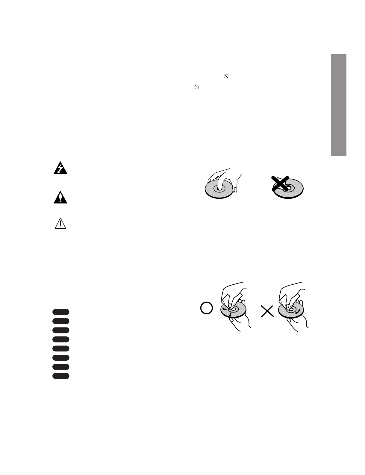
Handling Discs
Do not touch the playback side of the disc. Hold the
disc by the edges so that fingerprints do not get on
the surface. Never stick paper or tape on the disc.
Storing Discs
After playing, store the disc in its case. Do not expose
the disc to direct sunlight or sources of heat and
never leave it in a parked car exposed to direct sunlight.
Cleaning Discs
Fingerprints and dust on the disc can cause poor picture quality and sound distortion. Before playing,
clean the disc with a clean cloth. Wipe the disc from
the center out.
Do not use strong solvents such as alcohol, benzine,
thinner, commercially available cleaners, or anti-static
spray intended for older vinyl records.
Moisture Condensation
Never operate the DVD+VCR immediately after moving it from a cold location to a warm location. Leave it
for two or three hours without operating it. If you use
the DVD+VCR in such a situation, it may damage
discs/tapes and internal parts.
DivX
JPEG
WMA
MP3
CD
VCD
DVD-A
DVD-V
Introduction
Introduction
Page 12
1-11
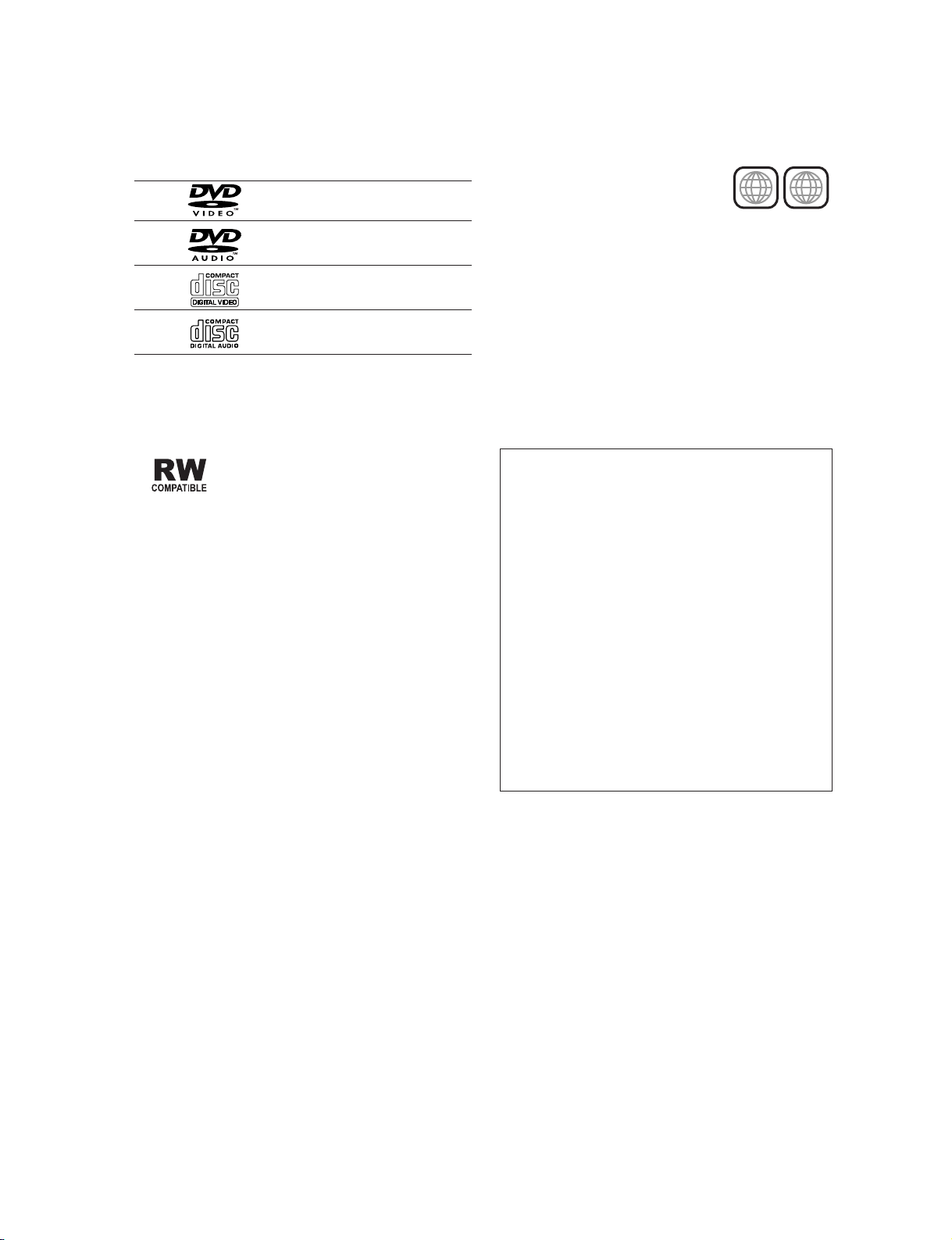
Types of Playable Discs
DVD video discs
(8 cm / 12 cm disc)
DVD audio discs
(8 cm / 12 cm disc)
Video CD (VCD)
(8 cm / 12 cm disc)
Audio CD
(8 cm / 12 cm disc)
In addition, this unit plays DivX file, DVD -R, DVD +R,
DVD -RW, DVD +RW, SVCD, and CD-R / CD-RW that
contains audio titles, MP3, WMA, and/or JPEG files.
This indicates a product feature that is
capable of playing DVD-RW discs
recorded with Video Recording format.
Notes:
• Refer to page 7 for more informations on disc-related terms.
• Depending on the conditions of the recording
equipment or the CD-R/RW (or DVD -R, DVD +R,
DVD -RW, DVD +RW) disc itself, some CD-R/RW
(or DVD -R, DVD +R, DVD -RW, DVD +RW) discs
cannot be played on the unit.
• Do not attach any seal or label to either side (the
labeled side or the recorded side) of a disc.
• Do not use irregularly shaped CDs (e.g., heartshaped or octagonal) since they may result in malfunctions.
Notes on DVDs and Video CDs
Some playback operations of DVDs and Video CDs
may be intentionally programmed by software manufacturers. This unit plays DVDs and Video CDs
according to disc content designed by the software
manufacturer, therefore some playback features may
not be available or other functions may be added.
Manufactured under license from Dolby
Laboratories. “Dolby”,“Pro Logic”, and the double-D symbol are trademarks of Dolby
Laboratories.
DTS and DTS Digital Out are trademarks of
Digital Theater Systems, Inc.
Regional code
This DVD+VCR is designed and
manufactured for playback of region
“2” encoded DVD software. This unit
can play only DVD discs labeled “2”
or “ALL”.
Notes on Regional Codes
• Most DVD discs have a globe with one or more
numbers in it clearly visible on the cover. This number must match your DVD+VCR’s regional code or
the disc cannot play.
• If you try to play a DVD with a different region code
from your player, the message “Check Regional
Code” appears on the TV screen.
2
ALL
Selecting the Viewing Source
You must select one of your output sources (DVD
or VCR) to view on the TV screen.
• If you want to view DVD deck output source:
Press DVD until DVD indicator in the display window
lights and output source of DVD deck is viewed on the
TV screen.
• If you want to view VCR deck output source:
Press VCR until VCR indicator in the display window
lights and output source of VCR deck is viewed on the
TV screen.
Notes:
• If you insert a disc while the DVD+VCR is in the
VCR mode, the DVD+VCR will switch to DVD
mode automatically.
• If you insert a cassette tape without prevention
tab while the DVD+VCR is in the DVD mode, the
DVD+VCR will switch to VCR mode automatically.
Page 13

1-12
Disc-related terms
DVD ±R / DVD ±RW
DVD -R and DVD +R are two different standards for
recordable DVD drives and discs. This format allows
information to be recorded onto the DVD disc only
once. DVD +RW and DVD -RW are two standards for
re-writable media, meaning the DVD content can be
erased and re-recorded. Single-sided discs can hold
4.38 Gigabytes and double-sided discs hold twice as
much. This player can only playback single sided
recordable discs.
VCD (Video CD)
A VCD holds up to 74 minutes (650 MB disc) or 80
minutes (700 MB disc) of MPEG-1 full-motion video
along with quality stereo sound.
MPEG
MPEG is an international standard for video and
audio compression. MPEG-1 is used in encoding
video for VCD and provides for multichannel surround
sound coding such as PCM, Dolby Digital, DTS and
MPEG audio.
MP3
MP3 is a popular compression format used for digital
audio files that yields very high near-CD quality.
WMA
Windows media audio file. A type of coding / decoding developed by Microsoft Corp.
JPEG
Joint Pictures Expert Group. JPEG is a compressed
file format that allows you to save images with no limit
on the number of colors.
DivX
DivX is the name of a revolutionary new video codec
which is based on the new MPEG-4 compression
standard for video.You will be able to play DivX
movies using this player .
PBC: Playback Control (Video CD only)
Playback control is available for Video CD (VCD) version 2.0 disc formats. PBC allows you to interact with
the system via menus, search functions, or other typical computer-like operations. Moreover, still pictures
of high resolution can be played if they are included
in the disc. Video CDs not equipped with PBC
(Version 1.1) operate in the same way as audio CDs.
Title (DVD video discs only)
A title is generally a distinct section of a DVD disc.
For example the main feature could be title 1, a documentary describing how the film was made could be
title 2, and cast interviews could be title 3. Each title
is assigned a reference number enabling you to
locate it easily.
Group (DVD audio discs only)
The main audio content or accompanying feature
content or additional feature content, or music album.
Each group is assigned a group reference number
enabling you to locate it easily.
Chapter (DVD video discs only)
A chapter is a segment of a title such as a scene in a
film or one interview in a series. Each chapter is
assigned a chapter number, enabling you to locate
the chapter you want. Depending on the disc, chapters may not be recorded.
Scene (VCD)
On a video CD with PBC (playback control) functions,
moving pictures and still pictures are divided into sections called “scenes”. Each scene is displayed in the
menu screen and assigned a scene number, enabling
you to locate the scene you want. A scene is composed of one or several tracks.
Track
A distinct element of audiovisual information, such as
the picture or sound track for a specific language
(DVD), or a musical piece on a video or audio CD.
Each track is assigned a track number, enabling you
to locate the track you want. DVD discs allow one
track of video (with multiple angles) and several
tracks of audio.
Introduction
Page 14

1-13
Front Panel
AV3
OPEN/CLOSE
Opens or closes the disc tray.
Remote Sensor
Point the DVD+VCR remote control here.
Display window
Shows the current status of the DVD+VCR.
Disc Tray (DVD deck)
Insert a disc here.
ON/STANBY
Switches the
DVD+VCR ON
and OFF.
AV3 (VIDEO IN/AUDIO IN (Left/Right))
Connect to the audio/video output of an external source (Audio
system, TV/Monitor, Another VCR).
Cassette Compartment (VCR deck)
Insert a video cassette here.
EJECT
Ejects the tape in the VCR deck.
DVD/VCR indicator
Indicates the active deck.
REC
To record normally or to
activate One-touch Timer
Recording by repeated
presses.
FWD
Advances the tape during the STOP mode
or for fast forward picture search.
REW
Rewinds the tape during the STOP
mode or for fast reverse picture search.
PLAY (ww)
Starts playback of a tape in the VCR deck.
PLAY (ww)
Starts playback of a
disc in the DVD deck.
STOP (■)
Stops playback of
disc.
STOP (■)
Stops playback of tape.
SKIP (B/F)
-
Skip to beginning of current chap-
ter or track, press twice in quick suc-
cessions to go to previous chapter
or track.
- Skip to next chapter or track.
Press and hold button for about two
seconds to search backward or for-
ward.
Page 15

1-14
DVD+VCR is in timer recording or a timer
recording is programmed.(VCR part only)
A cassette is in the VCR deck.
The VCR deck is selected.
DVD+VCR is Recording.
(VCR part only)
Lights when TV mode is active (see page 26).
A disc is in the DVD deck.
(Lights when a disc is in the DVD deck
and Flashes when no disc.)
Indicates when the Progressive scan is active.
Indicates total playing time, elapsed time, remaining time or
current deck status (Playback, Pause, etc).
The DVD deck is selected.
Indicates repeat mode.
Display Window
Introduction
DVD
[P]
VCR
REC
TV
Page 16
1-15
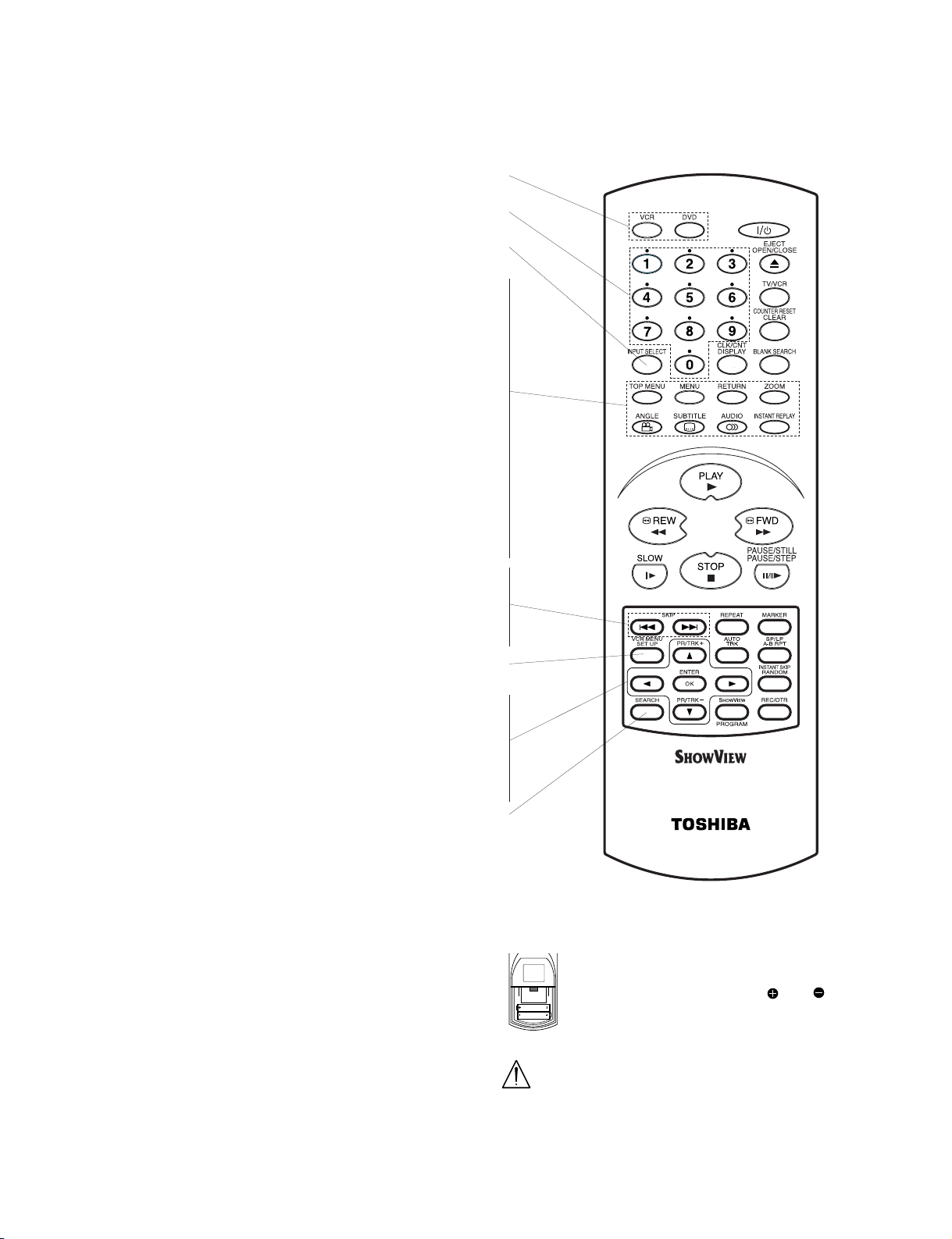
Remote Control
DVD/VCR select button
Select the output source (DVD or VCR) to view on the TV screen.
0-9 numerical buttons
Selects numbered options in a menu.
INPUT SELECT
To select the VCR deck’s source (Tuner, AV1, AV2 or AV3).
TOP MENU
Displays the disc’s Title menu, if available.
MENU
Accesses menu on a DVD disc.
RETURN
Removes the setup menu.
ZOOM
Enlarges video image.
ANGLE
Selects a DVD camera angle if available.
SUBTITLE
Selects a subtitle language (DVD).
AUDIO
Selects an audio language (DVD) or an audio channel (VCD).
INSTANT REPLAY
Replays through 10 seconds of DVD playback.
SKIP B
Skip to beginning of current chapter or track,
press twice in quick successions to go to previous chapter or track.
SKIP F
Skip to next chapter or track.
SET UP, VCR MENU
Accesses or removes DVD setup menu and VCR menu.
W/w/v/V (left/right/up/down)
- Selects an option in the menu
- PR/TRK (+/-): Selects channel of VCR. Adjusts manually the
tape’s picture onscreen.
ENTER/OK
- Acknowledges menu selection.
- Displays functions on the TV screen.
SEARCH
Displays MARKER SEARCH menu.
Remote Control Operation
Point the remote control at the remote sensor and
press the buttons.
Distance: About 23 ft (7 m) from the front of the
remote sensor
Angle: About 30° in each direction of the front of the
remote sensor
Remote Control Battery installation
Detach the battery cover on the rear of
the remote control, and insert two
(R03/AAA) size batteries with and
aligned correctly.
Do not mix old and new batteries and never
mix different types of batteries such as standard, alkaline, etc.
AAA
AAA
Page 17
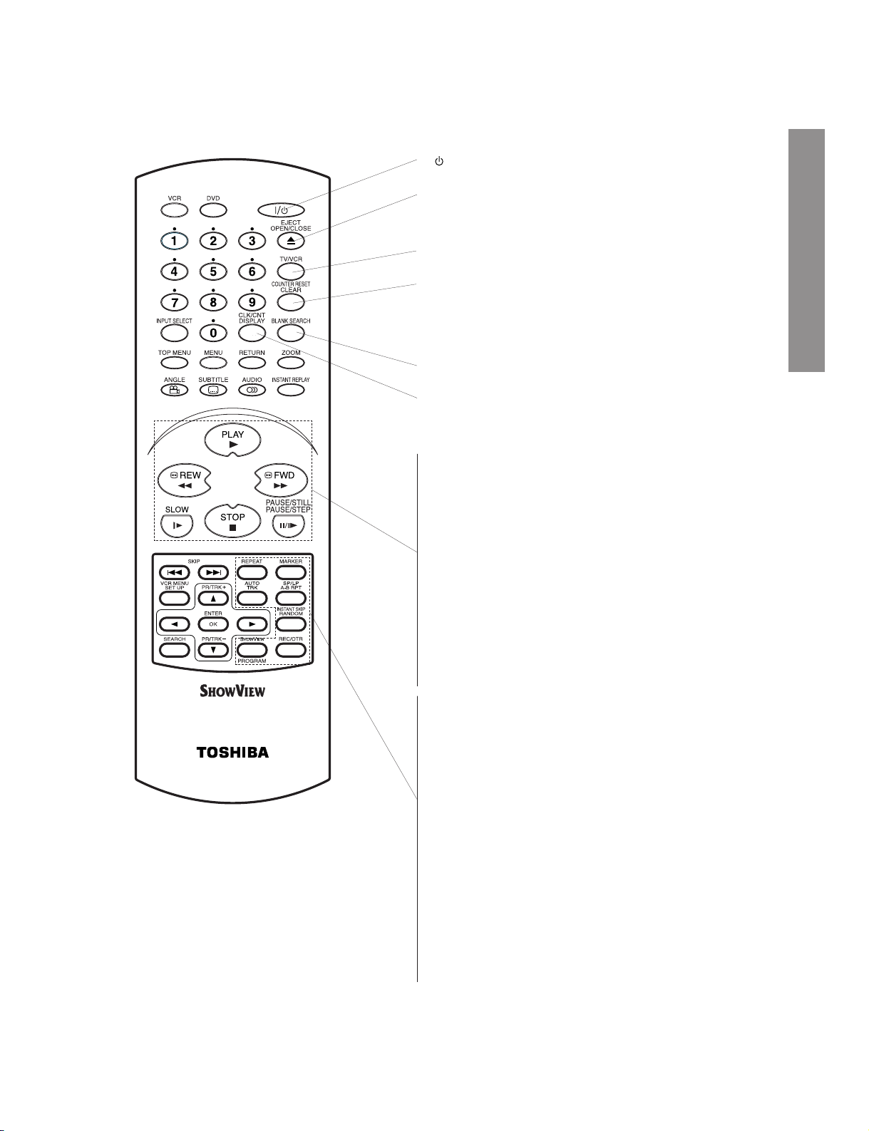
1-16
I/ (POWER)
Switches DVD+VCR ON and OFF.
EJECT, OPEN/CLOSE
- Opens and closes the disc tray.
- Ejects the tape in the VCR deck.
TV/VCR
To view channels selected by the VCR tuner or by the TV tuner.
COUNTER RESET, CLEAR
- Resets tape counter to M 0:00:00.
- Removes a track number on the
program menu or a mark on the
MARKER SEARCH menu.
BLANK SEARCH
Finds end points of recording.
CLK/CNT, DISPLAY
Accesses On-Screen display.
Switches among the clock, tape counter and tape remaining modes
on the display.
PLAY
Starts playback.
REW
- Rewinds the tape during the STOP.
- To fast reverse picture search.
FWD
- Advances the tape during the STOP.
- To fast forward picture search.
SLOW
Forward slow playback.
STOP
Stops playback.
PAUSE/STILL, PAUSE/STEP
- Pause playback or recording.
- Press repeatedly for frame-by-frame playback during pause.
REPEAT
Repeat chapter, track, title, group, all.
MARKER
Marks any point during playback.
AUTO TRK
Adjusts automatically the tape’s picture onscreen.
A-B RPT (REPEAT), SP/LP
- Repeats sequence.
- Selects recording speed of the tape.
RANDOM, INSTANT SKIP
- Plays tracks in random order.
- Fast forwards picture search through 30 seconds of recording.
SHOWVIEW/PROGRAM
-
To display the programme menu for SHOWVIEW programming.
-
Accesses or removes Program menu.
REC/OTR
Records normally or activates One- touch Timer Recording with
repeated presses.
Remote Control
Introduction
Page 18
1-17
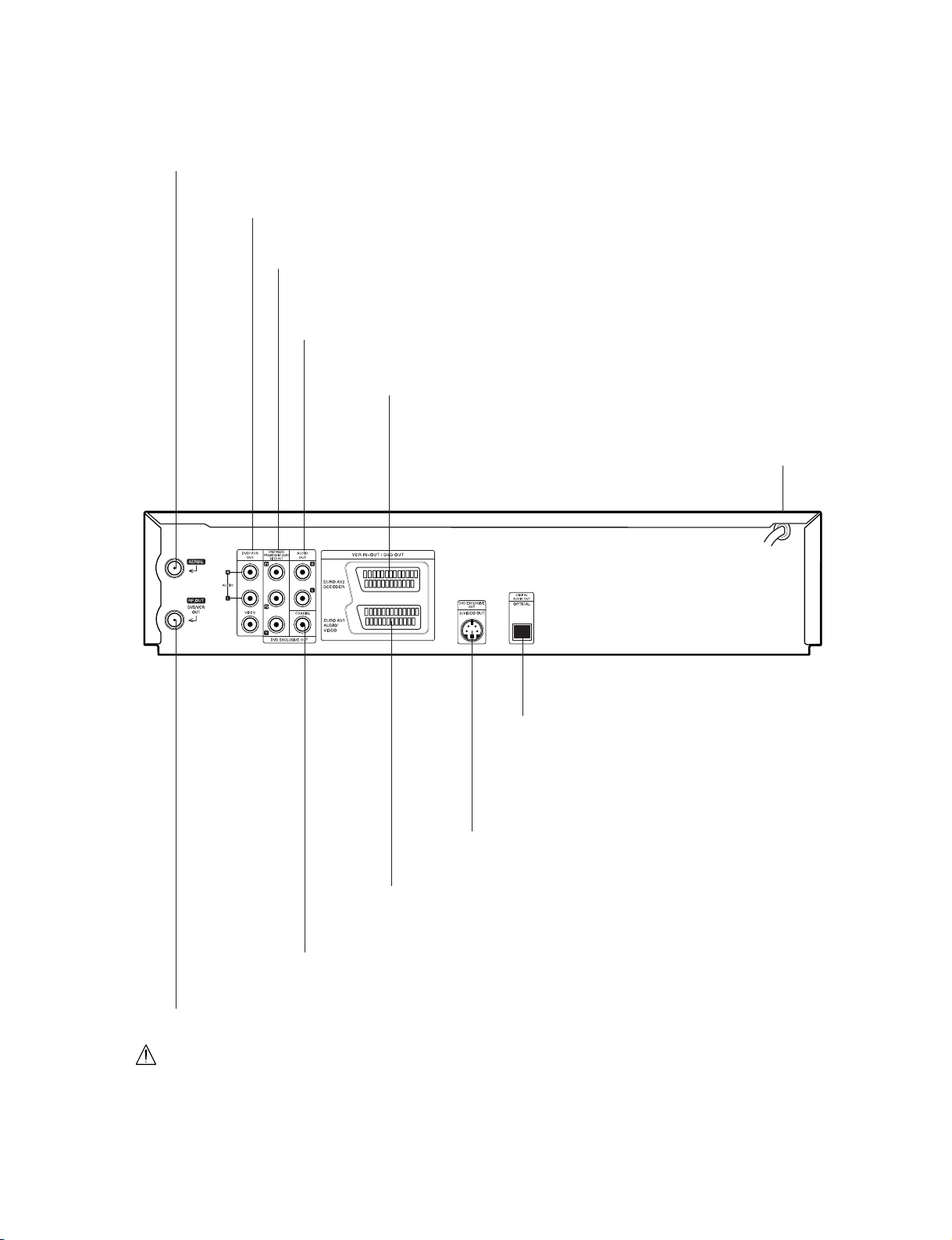
Rear Panel
DVD/VCR OUT (VIDEO/AUDIO (Left/Right))
Connect to a TV with video and audio inputs.
AUDIO OUT (Left/Right) (DVD EXCLUSIVE OUT)
Connect to an amplifier, receiver or stereo system.
AERIAL
Connect the aerial using this jack.
EURO AV2 DECODER
Connect to pay-TV decoder, Set Top Box or another
video recorder.
EURO AV1 AUDIO/VIDEO (VCR IN+OUT/DVD OUT)
Connect to your TV set or another video recorder.
RF.OUT (DVD/VCR OUT)
Connect to your TV using this jack.
AC Power Cord
Connect to a power source.
S-VIDEO OUT (DVD EXCLUSIVE OUT)
Connect to a TV With S-Video input.
COMPONENT/PROGRESSIVE SCAN VIDEO OUT (Y Pb Pr)
(DVD EXCLUSIVE OUT)
Connect to a TV With Y Pb Pr inputs.
OPTICAL (DVD EXCLUSIVE OUT)
(Digital audio out jack)
Connect to digital (optical) audio equipment.
COAXIAL (DVD EXCLUSIVE OUT)
(Digital audio out jack)
Connect to digital (coaxial) audio equipment.
Do not touch the inner pins of the jacks on the rear panel.
Electrostatic discharge may cause permanent damage to the unit.
Page 19

1-18
Tips:
• Depending on your TV and other equipment you wish to
connect, there are various ways you could connect the
unit.
• Please refer to the manuals of your TV, Stereo System or
other devices as necessary to make the best connections.
• For better sound reproduction, connect this unit’s AUDIO
OUT jacks to the audio in jacks of your amplifier, receiver,
stereo or audio/video equipment. See “Connecting to
Optional Equipment” on page 14.
Caution:
• This DVD+VCR only support PAL system (refer to VCR
part only).
• Make sure this unit is connected directly to the TV. Set the
TV to the correct video input channel.
• Do not connect this unit’s AUDIO OUT jack to the phono
in jack (record deck) of your audio system.
Connecting to a TV and
Decoder (or Set Top Box)
• Make one of the following connections, depending
on the capabilities of your existing equipment.
• RGB signal is only exclusive for DVD playback.
Basic connection (AV)
1. Connect the EURO AV1 AUDIO/VIDEO on the
rear panel of this unit to the SCART input socket
on the TV using a SCART lead (not supplied).
For TV without SCART, connect the yellow VIDEO
OUT jack and DVD/VCR AUDIO OUT jacks of this
unit to the TV.
2. Some TV broadcasters transmit encoded televi-
sion signals which you can only see with a purchased or rented decoder.You can connect such
a decoder (descrambler) to this unit.
Basic connection (RF)
1. Connect the RF antenna cable from your indoor/
outdoor antenna to AERIAL jack on the rear
panel of this unit.
2. Connect the supplied RF antenna cable from the
RF.OUT (DVD/VCR OUT) jack on the rear panel
of this unit to your television’s Antenna Input.
S-Video connection
1. Connect the S-VIDEO OUT jack on this unit to the
S-Video in jack on the TV using the S-Video cable
(not supplied).
2. Connect the Left and Right
AUDIO OUT (DVD
EXCLUSIVE OUT) jacks of this unit to the audio
left/right in jacks on the TV using the audio
cables.
Component (Color Stream®) / Progressive
Scan (ColorStream
®
pro) Video connection
(DVD EXCLUSIVE OUT)
1. Connect the COMPONENT/PROGRESSIVE
SCAN VIDEO OUT (DVD EXCLUSIVE OUT)
jacks on the DVD+VCR to the corresponding in
jacks on the TV using an Y Pb Pr cable (not supplied).
2. Connect the Left and Right
AUDIO OUT (DVD
EXCLUSIVE OUT) jacks of the DVD+VCR to the
audio left/right in jacks on the TV using the audio
cables.
Notes:
• If your television is a high-definition or “digital ready” tele-
vision, you may take advantage of the DVD+VCR’s pro-
gressive scan output for the highest video resolution possible.
• Set the Progressive Scan to “On” on the setup menu for
progressive scan signal, see page 22.
• When you use Component Video signal (interlace mode),
set the Progressive Scan to “Off” on the setup menu.
• If you set Progressive Scan to ON in error, you must reset
the DVD+VCR. First, remove the disc in the DVD+VCR.
Next, press STOP (
■) and hold it for five seconds before
releasing it. The video output will be restored to the standard setting, and a picture will once again be visible on a
conventional analog TV or monitor.
• If the TV has an S-video input, connect the DVD+VCR
with the S-video cable. When using an S-video cable, do
not connect the yellow video cable.
Preparation
Introduction
Page 20

1-19
Connecting to Optional
Equipment
Connecting to an amplifier equipped with
two channel analog stereo or Dolby
Surround.
Connect the Left and Right DVD/VCR AUDIO OUT or
AUDIO OUT (DVD EXCLUSIVE OUT) jacks on this
unit to the audio left and right in jacks on your amplifier, receiver or stereo system, using the audio cables.
Connecting to an amplifier equipped with
two channel digital stereo (PCM) or to an
Audio/ Video receiver equipped with a multichannel decoder (Dolby Digital™, MPEG 2 or
DTS)
1. Connect one of this unit’s DIGITAL AUDIO OUT
jack (COAXIAL or OPTICAL) to the corresponding in jack on your amplifier. Use an optional digital (optical or coaxial) audio cable.
2. You will need to activate this unit’s digital output.
(See “AUDIO” on page 22).
Digital Multi-channel sound
A digital multi-channel connection provides the best
sound quality. For this you need a multi-channel
Audio/Video receiver that supports one or more of the
audio formats supported by your unit (MPEG 2, Dolby
Digital and DTS). Check the receiver manual and the
logos on the front of the receiver.
Warning:
Due to the DTS Licensing agreement, the digital output will be in DTS digital out when DTS audio stream
is selected.
Notes:
• If the audio format of the digital output does not
match the capabilities of your receiver, the receiver
will produce a strong, distorted sound or no sound
at all.
• Six Channel Digital Surround Sound via digital
connection can only be obtained if your receiver is
equipped with a Digital Multi-channel decoder.
• To see the audio format of the current DVD in the
On-Screen Display, press
AUDIO.
Rear of this unit (Component/Progressive scan Video connection)
Rear of TV
VIDEO INAERIAL
COMPONENT/PROGRESSIVE SCAN VIDEO INPUT
Pb
Pr
AUDIO INPUT
L
Y
SCART INPUT
R
Decoder or Set Top Box
S-
VIDEO OUT
Rear of this unit (Basic connection)
Rear of this unit
2 channel analog stereo or Dolby Surround connection.
DVD exclusive out
R
L
AUDIO INPUT
COAXIAL
DIGITAL INPUT
Amplifier (Receiver)
Digital multi-channel
connection
OPTICAL
DIGITAL INPUT
Page 21

1-20
Tuning in a video channel on
your TV
Notes:
• The output frequency of this video recorder
(VCR) is set at UHF channel 60. If channel 60
is already used by another TV station, or if the
picture is distorted, you can change the
transmitter channel of your DVD+VCR. Stages
5 ~ 8 will show you how to change the output
frequency of your DVD+VCR.
• Your TV receives signals from the video
recorder (VCR) like another TV station. You
have to select a channel number on your TV
and tune it in so that you may watch video
tapes. If you have used a
SCART then your
TV should already have a dedicated video
channel built into it, usually called AV.
1. Make sure that you have correctly installed your
DVD+VCR as described earlier in this book.
Press
I/ to turn on your DVD+VCR.
Turn on your TV.
2. Insert a pre-recorded video tape into your
DVD+VCR and press
PLAY wwon the remote con-
trol.
Select a TV channel number on which you wish to
watch video’s.
Don’t worry if you don’t have a video-tape to play
at this stage! If you switch your DVD+VCR on and
continue stages
3 ~ 4, instead of seeing video
playback tune your TV until you see a bright blue
screen.
3. Tune this channel until the video picture is sharp
and the sound is clear.
If you have used a
SCART or AUDIO and VIDEO
cables you will not have to tune your TV, simply
select the AV channel.The
AV channel is already
pre-tuned for optimum video playback on your TV.
4. Store this channel on your TV.
You will need to look at the TV instruction book if
you do not know how to do this.
5.
Only carry out stages 5 ~ 8 if you cannot
obtain clear video playback as described in
stages 1 ~ 4.
Select a TV channel number on
which you wish to watch video’s.
Make sure that your DVD+VCR is in standby
pressing
I/ on the remote control (only the clock
will be displayed).
6. Press
REW
bb
or FWD
ff
on the front of
your DVD+VCR for more than 4 seconds.
RF60 will appear in the display window.
The following picture will be displayed on the TV
screen.
7. Use
bb
or FWD
ff
to select another video
channel. You may select any channel number
between 22 and 68.
You can also set it to “OFF” if there is any
interference when your TV is connected to the
VCR with a SCART lead.
8. Select a TV channel number on which you wish to
watch video’s.
Press
ON/STANDBY I/ on the front of your
DVD+VCR when you have finished.
Tune this channel so that a bright blue screen
appears. Store this channel on your TV.
Notes:
Make sure that you have correctly installed your
DVD+VCR and successfully tuned in a dedicated video channel on your TV. If you do not tune
in a dedicated video channel on your TV you
will be unable to view and record video tapes!
Using your DVD+VCR for the
very first time
The following picture will be displayed on the TV
screen when you have just connected your DVD+VCR
for the very first time.
To activate tuning of TV stations, please follow stages
3 to 4 of “Tuning in TV Stations Automatically” in page
17.
i
RF CHANNEL 60
P
SET
R
A
NNL PSSF
ANDERE
B D DK E FI
OK
i
Pr-12
ACMS
CH
Preparation
Page 22
1-21
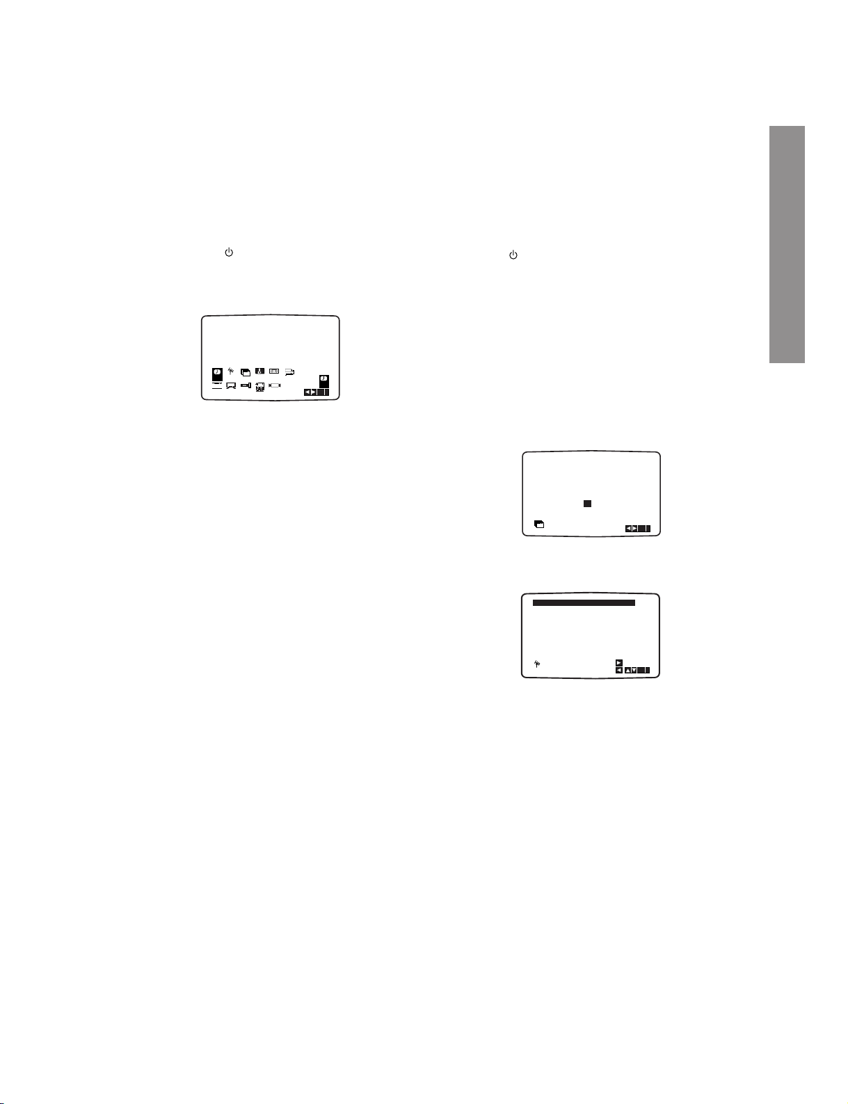
Setting the clock Manually
The clock in your DVD+VCR controls time and
date settings for your DVD+VCR.
The clock is set automatically during ACMS
(Automatic Channel Memory System) when
your DVD+VCR detects a channel that broadcasts a Teletext signal. If the broadcast signal is
weak the clock will not be set and will require
setting manually.
1. Press VCR MENU.
Press
WW
or wwto select TIME DATE.
Press
ENTER/OK.
The auto adjust mode can be set to “OFF” by
pressing
vvorVV
if you want to set the time
manually.
Press
ENTER/OK.
2. Use the
numbered buttons on the remote control
to alter the HOURS, MINUTES, DAY, MONTH and
YEAR.
Please note your DVD+VCR uses a 24 hour
clock. e.g. 1pm will be displayed as 13:00.
The day of the week will appear automatically
when you enter the year.
3. If you make a mistake press
WW
or wwand enter the
correct details.
4. Press
VCR MENU to return to a TV picture.
To set the colour system
1. Press VCR MENU.
2. The main menu will appear on the TV screen.
3. Press
WW
or wwto select the SYSTEM and press
ENTER/OK.
4. Press
v or V to select according to the
COLOUR system used.
5. Press
VCR MENU to remove the menus from the
TV screen.
To set the RF OUT sound
system
1. Press VCR MENU.
2. The main menu will appear on the TV screen.
3. Press
WW
or wwto select the SYSTEM and press
ENTER/OK.
4. Press
v or V to select according to the
COLOUR system used.
5. Press
ww
to select the RF Out sound system com-
patible to your TV.
6. Press
VCR MENU to remove the menus from the
TV screen.
HH MM DD MM YY
:..- -
- -
- - - -
- - - - -
i
12
TIME
DATE
HH MM DD MM YY
:..00 1 01 04 THU
i
12
TIME
DATE
8
AUTO ADJUST
- -
i
12
TIME
DATE
ON:
OK
REC
i
Pr-12
ACMS
P
SET
R
12
TIME
DATE
SYS-
TEM
SYS-
TEM
Dr.
VCR
OSD
ON
OFF
OSD
f
16:9
4:3
OPR
NIC
DECO-
DER
+
-
AUTO
PAL
MESECAM
REC
i
Pr-12
ACMS
P
SET
R
12
TIME
DATE
SYS-
TEM
SYS-
TEM
Dr.
VCR
OSD
ON
OFF
OSD
f
16:9
4:3
OPR
NIC
DECO-
DER
+
-
RF I / I
RF B/G
RF D/K
Page 23
1-22
How to use the main menu
This DVD+VCR can easily be programmed by
using the menus displayed on screen.
The menus are controlled from the Remote
Control Handset.
1. Switch on your TV set and video recorder by
pressing the I/ button.
2. Press
VCR MENU button.
The main menu will appear on the TV screen.
• REC - Timer recording setting (see p. 27).
• PR SET - Manual tuning setting (see p. 18).
• ACMS - ACMS (Automatic Channel Memory
System) (see p. 17).
• TIME DATE - Date & clock setting (see p. 16).
• SYSTEM - To set the Colour TV System
(see p. 16).
• Dr. - To check a problem with your VCR
(see p. 42).
• F.OSD ON/OFF - To display the operational
mode of your VCR (see
p. 41).
• 16:9/4:3 - To select the aspect ratio of your TV
(see p. 42).
• DECODER - To use a pay-TV decoder (or
Satellite) with your VCR (see
p. 43).
• OPR - To improve the playback picture
(see p. 25).
• NIC - To activate or deactivate the NICAM digi-
tal sound (see p. 41).
3. Press
WW
or wwto select the desired menu.
Press
ENTER/OK and use v or V to select.
4. Press
VCR MENU to return to a TV picture.
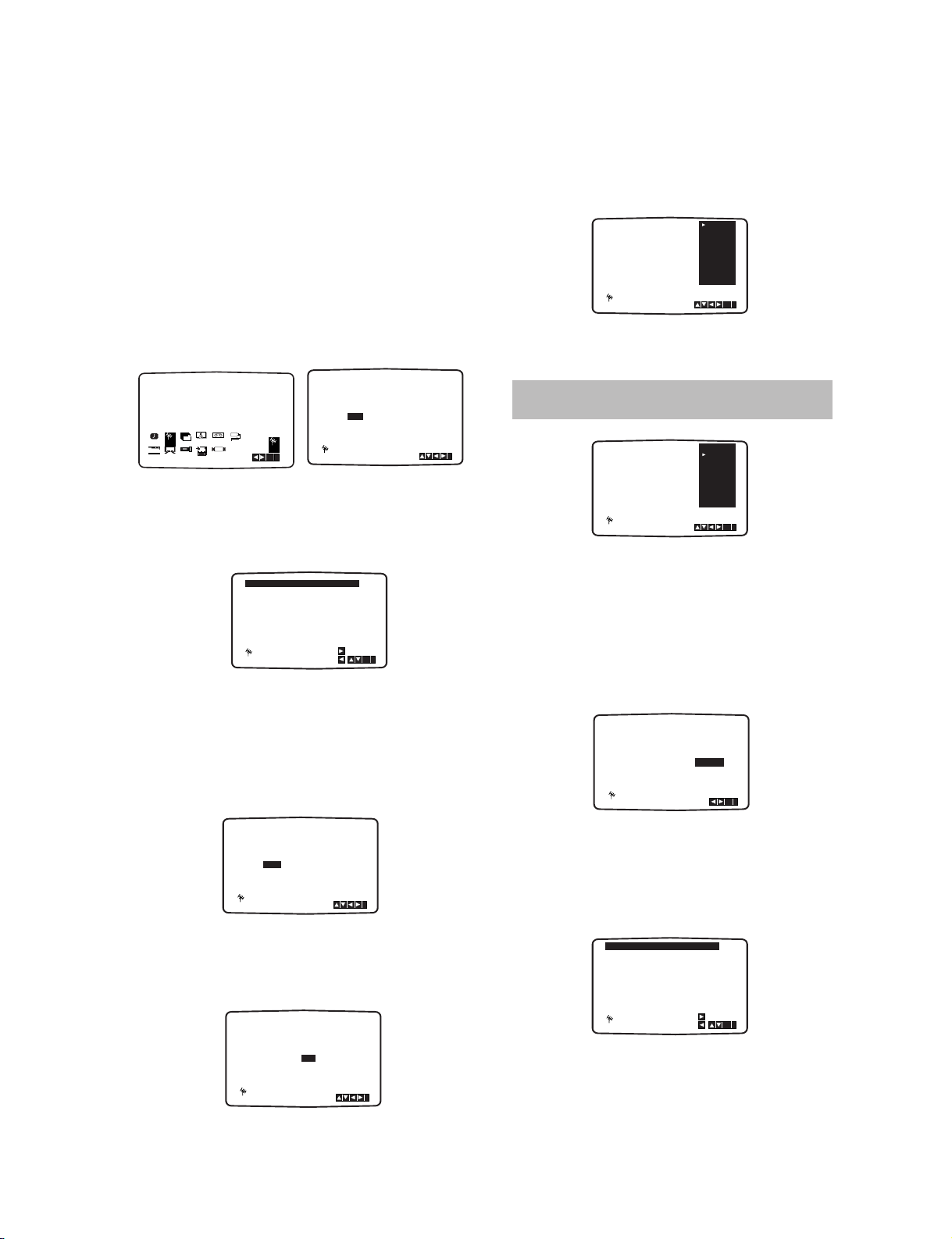
Tuning in TV Stations Automatically
If the TV broadcast signal is weak your
DVD+VCR may not detect the necessary information and will not be able to store them correctly. To overcome this problem please turn to
the MANUAL TUNING section on page 18.
1. Press I/ to turn on your DVD+VCR.
2. Press
VCR MENU button.
The main menu will appear on the TV screen.
Press
v or V to select the ACMS.
Press
ENTER/OK.
3. Press
v or V to select COUNTRY.
(
A:Austria, B:Belgium, CH:Switzerland,
D:Germany, DK:Denmark, E:Spain, F:France,
I:Italy, N:Norway, NL:Nertherlands, P:Portugal,
S:Sweden, SF:Finland, Others)
Press
ENTER/OK to start the automatic tuning
process.
4. The TV STATION TABLE will appear when tuning
is completed.
Press
VCR MENU to save your settings.
Notes:
• The DVD+VCR’s clock will be set automatically
when automatic tuning has finished. If the clock is
wrong please see “Setting the clock Manually” on
page 16.
• Please note currently only a limited number of TV
companies transmit the
Programme Delivery
Control (PDC) signal which enables your
DVD+VCR to successfully identify and store them.
If your DVD+VCR has difficulty in identifying a TV
station please turn the page to find out how to
manually tune in and name a TV station. While
automatic tuning is taking place the time and date
will set automatically.
If - - :- - appears in the DVD+VCR display it means
that the broadcast signal is weak and the clock was
not set. Please turn to
CLOCK SET section of this
book on page 16.
02 C03 00
03 C04 00
04 C05 00
05 C06 00
06 C07 00
07 C08 00
08 C09 00
01 C02 00
OK
i
,DELETE :
MOVE :
P
SET
R
ZDF
WDR 3
BR3
HR3
N 3
NDR 3
SWF3
ARD
REC
REC
OK
i
SYS-
TEM
P
SET
R
Pr-12
ACMS
OSD
ON
OFF
OSD
f
12
TIME
DATE
16:9
4:3
Dr.
VCR
OPR
DECO-
DER
+
-
NIC
A
NNL PSSF
OTHERS
B D DK E FI
OK
i
Pr-12
ACMS
CH
Preparation
Page 24
1-23
Tuning in TV Stations Manually
In certain areas of the country broadcast signals
may be too weak for your DVD+VCR’s automatic tuning process to find or assign TV stations
correctly. You must tune in these weaker broadcast stations manually in order for your
DVD+VCR to store them.
1. Press VCR MENU.
The main menu will appear on the TV screen.
Press
WW
or wwto select the PR SET.
Press
ENTER/OK.
2. Press VCR MENU.
The station table will appear.
Press
v or V to select the programme number
that you want to tune (for example, PR 09).
3. Press
ENTER/OK.
Press INPUT SELECT to select C (Standard
stations) or S (Cable stations):
C02 - C69, S01 - S41.
Enter the channel number of station that you want
to tune with
the numbered buttons or use v or
V to find the required station.
4. Searching will stop when it locates a stations.
Press
to select MFT.
Control the fine tuning of the station by using v
or V.
5. Press
ww
to select STATION so that you may
name your TV station.
Press
ENTER/OK.
The TV station name list will appear.
6. Use
D or E to select a station name from the list.
Press ENTER/OK to select it.
7. You can change a TV station name manually
rather than using the “standard” names.
Press
G.
Use
v or V to select letters and numbers for
the new station name.
Use
WW
or wwto move back and forth between
characters.
Press
ENTER/OK.
8. Press VCR MENU, confirm the station placement.
Press VCR MENU again.
Your new TV station has now been tuned into your
DVD+VCR.
If you wish to manually tune other stations repeat
stages
1 - 8.
PR CH MFT STATION
01 00
CHANNEL/CABLE : AV
C 02
P
SET
R
i
PR-01
OK
i
,DELETE :
MOVE :
P
SET
R
02 C03 00 PR-02
03 C04 00 PR-03
04 C05 00 PR-04
05 C06 00 PR-05
06 C07 00 PR-06
07 C08 00 PR-07
08 C09 00 PR-08
01 C02 00 PR-01
PR CH STATION
09 - - - - - -
MFT
P
SET
R
C - -
CHANNEL/CABLE : AV
i
PR CH STATION
09 00
C10
MFT
CHANNEL/CABLE : AV
i
P
SET
R
i
- - - -
PR CH MFT
09 00
P
SET
R
C10
i
OK
ZDF
WDR 3
BR3
HR3
N 3
NDR3
SWF3
ARD
PR CH MFT
09 00
P
SET
R
C10
i
OK
ZDF
WDR 3
BR3
HR3
N 3
NDR3
SWF3
ARD
PR CH MFT
STATION
C09 00
C10
ZDF
i
OK
P
SET
R
11
12
13
14
15
- - - - - - - - -
- - - - - - - - -
- - - - - - - - -
- - - - - - - - -
- - - - - - - - -
- - - - - - - - -
- - - - - - - - -
09 C10 00 ZDF
16
10
OK
i
,DELETE :
MOVE :
P
SET
R
OK
i
P
SET
R
P
SET
R
REC
SYS-
TEM
Dr.
VCR
OSD
ON
OFF
OSD
f
16:9
4:3
12
TIME
DATE
OPR
NIC
DECO-
DER
+
-
Pr-12
ACMS
If your station name isn’t on the list do not press
ENTER/OK, but go to stage 7.
Page 25
1-24
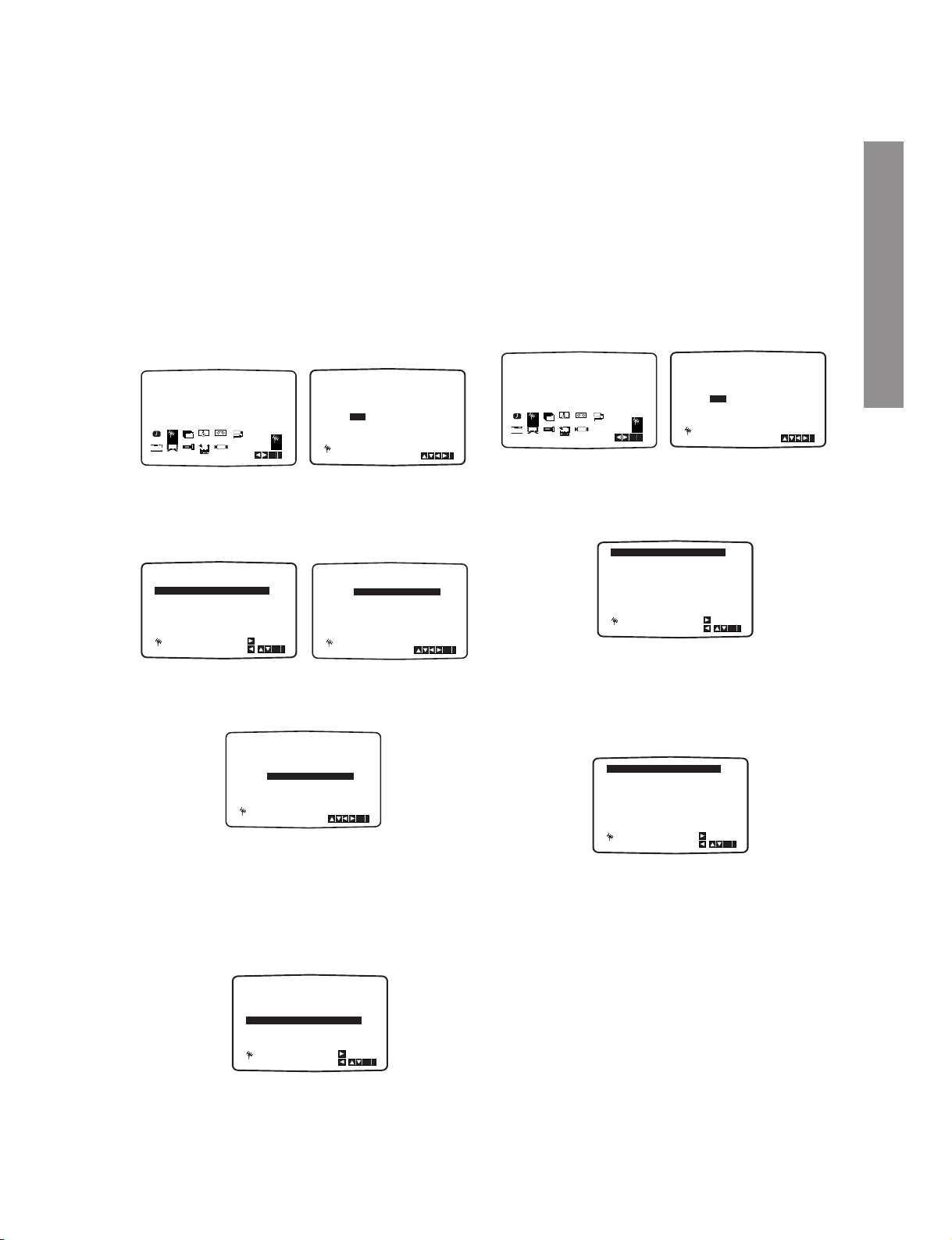
Changing the order of TV Stations
After tuning TV stations into your DVD+VCR you
may wish to change the order in which they are
stored without having to retune them again. The
instructions given on this page will show you how
you can simply move them into your desired
order.
1. Press VCR MENU.
The main menu will appear on the TV screen.
Press
WW
or wwto select the PR SET.
Press
ENTER/OK.
2. Press VCR MENU.
Press
v or V to select the programme number
you want to move (for example, PR-03).
Press
ww
.
3. Press
v or V to select the programme number
you want to move to (for example, PR-05).
4. Press ENTER/OK.
The selected programme will be moved to the
new programme number.
If you wish to move other TV stations repeat stages
1 - 4.
Press
VCR MENU to remove the menus from the
TV screen.
Deleting TV Stations
After tuning TV stations into your VCR you may
wish to delete a station.
The instructions given on this page will show you
how you can easily delete any unwanted TV
stations.
1. Press VCR MENU.
The main menu will appear on the TV screen.
Use
WW
or wwto select the PR SET.
Press
ENTER/OK.
2. Press VCR MENU.
3. Press v or V to select the programme number
you want to delete. (for example, PR-01)
4. Press
.
After a short while, the selected station will be
deleted.
If you wish to delete other TV stations repeat
stages
3 - 4.
5. Press VCR MENU to remove the menus from the
TV screen.
How to select Stored TV stations:
Stored TV stations can be selected in either of two
ways.
Use
PR/TRK + or - to select different stations that
are tuned into your DVD+VCR.
You may also directly select stations using the
numbered buttons on the remote control.
OK
i
,DELETE :
MOVE :
P
SET
R
02 C03 00 PR-02
03 C04 00 PR-03
04 C05 00 PR-04
05 C06 00 PR-05
06 C07 00 PR-06
07 C08 00 PR-07
08 C09 00 PR-08
01 C02 00 PR-01
OK
i
,DELETE :
MOVE :
P
SET
R
- - - -
02
C03
00
03
C04
00
04
C05
00
05
C06
00
06
C07
00
07
C08
00
08
C09
01 00
PR-02
PR-03
PR-04
PR-05
PR-06
PR-07
PR-01
- - - - -
OK
i
,DELETE :
MOVE :
P
SET
R
02 C03 00 PR-02
03 C05 00 PR-03
04 C06 00 PR-04
05 C04 00 PR-05
06 C07 00 PR-06
07 C08 00 PR-07
08 C09 00 PR-08
01 C02 00 PR-01
OK
i
,DELETE :
MOVE :
P
SET
R
02 C03 00 PR-02
03 C04 00 PR-03
04 C05 00 PR-04
05 C06 00 PR-05
06 C07 00 PR-06
07 C08 00 PR-07
08 C09 00 PR-08
01 C02 00 PR-01
OK
i
P
SET
R
P
SET
R
REC
SYS-
TEM
Dr.
VCR
OSD
ON
OFF
OSD
f
16:9
4:3
12
TIME
DATE
OPR
NIC
DECO-
DER
+
-
Pr-12
ACMS
PR CH MFT STATION
01 00 PR-01
CHANNEL/CABLE : AV
C 02
P
SET
R
i
P
SET
R
02 C03 00 PR-02
03 C05 00 PR-04
04 C06 00 PR-05
05 C04 00 PR-03
06 C07 00 PR-06
07 C08 00 PR-07
08 C09 00 PR-08
01 C02 00 PR-01
OK
i
P
SET
R
02 C03 00 PR-02
03 C05 00 PR-04
04 C06 00 PR-05
05 C04 00 PR-03
06 C07 00 PR-06
07 C08 00 PR-07
08 C09 00 PR-08
01 C02 00 PR-01
OK
i
OK
i
P
SET
R
P
SET
R
REC
SYS-
TEM
Dr.
VCR
OSD
ON
OFF
OSD
f
16:9
4:3
12
TIME
DATE
OPR
NIC
DECO-
DER
+
-
Pr-12
ACMS
PR CH MFT STATION
01 00 PR-01
CHANNEL/CABLE : AV
C 02
P
SET
R
i
Preparation
Page 26

1-25
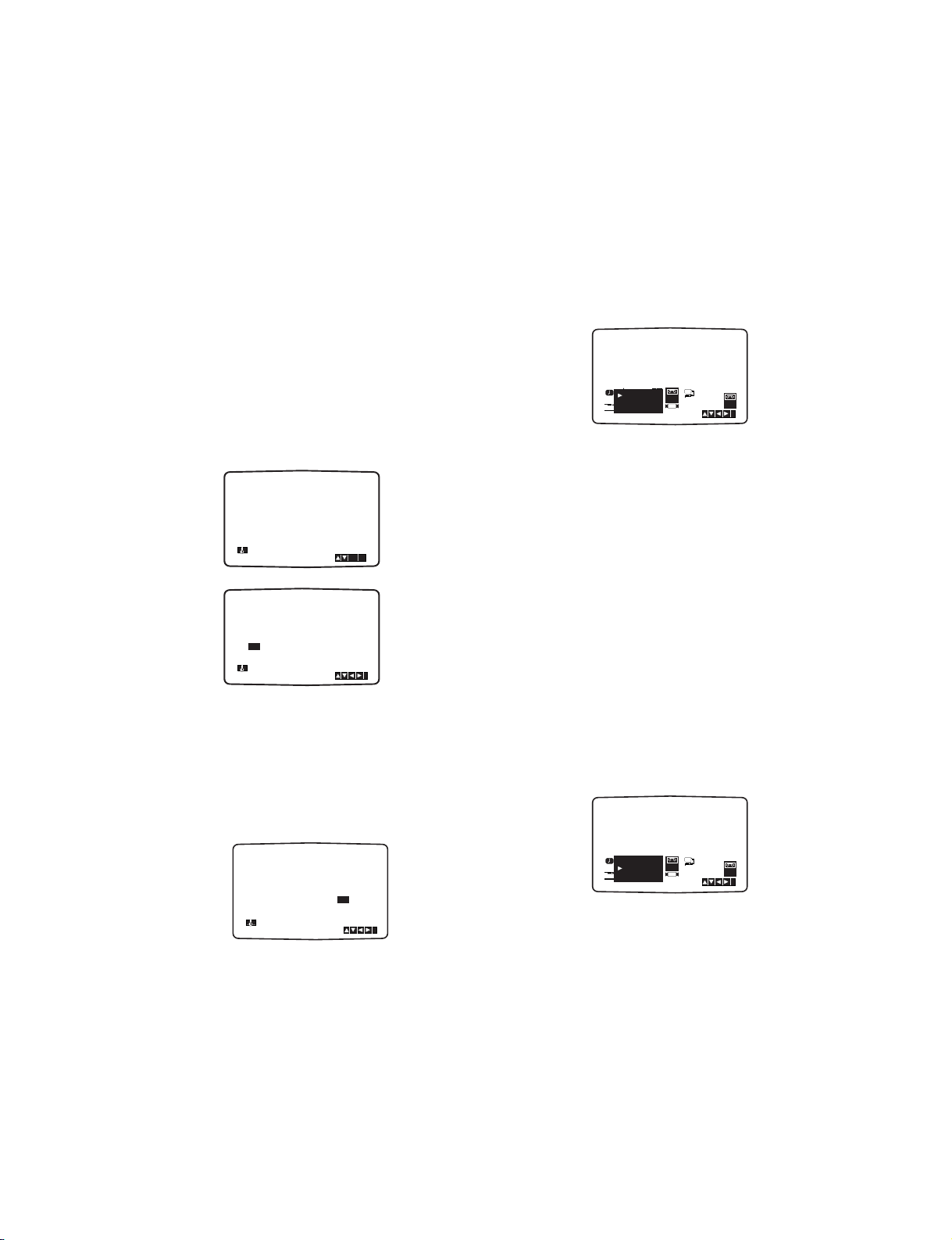
DVD On-Screen Display
You can display the general playback status on the
TV screen. Some items can be changed using the
menu. To use the on-screen display:
1. Press DISPLAY during playback.
2. Press
v /V to select an item.
The selected item is highlighted.
3. Press
WW/ ww
to change the setting. You can also
use the number buttons if appropriate (e.g.
inputting the title number). For some functions,
press ENTER/OK to execute the setting.
Notes:
• Some discs may not provide all of the features
shown below.
• If no button is pressed for 10 seconds, the onscreen display disappears.
Playback Status/Restrictions
Repeat title
Repeat sequence
Enter a Marker
Marker Search menu
Resume play from this point
Action prohibited or not available
Example: On-Screen Display during
playing VCD
Items
Title Number
Chapter Number
Time search
Audio language
and Digital Audio
Output mode
Subtitle language
Angle
Sound
Selection Method
W/w
, Numbers
ENTER/OK
W/w
, Numbers
ENTER/OK
Numbers, ENTER/OK
W/w
or
AUDIO
W/w
or
SUBTITLE
W/w
or
ANGLE
W/w
1 / 3
1 / 12
0:20:09
CH
A
B
C
1 ENG
1 / 3
3D SUR
Example: On-Screen Display during
playing DVD Video
Items
Track Number
(or PBC mode)
Time search
Audio Channel
Sound
Selection Method
W/w
, Numbers
ENTER/OK
Numbers
ENTER/OK
W/w
or
AUDIO
W/w
1 / 3
0:20:09
3D SUR
Items
Group Number
Track Number
Time search
DVD Audio
Output mode
Subtitle language
Page (or Angle)
Sound
Selection Method
W /w
, Numbers
ENTER/OK
W /w
, Numbers
ENTER/OK
Display only
W /w
or
AUDIO
Display only
W /w
or
ANGLE
W /w
1 / 2
1 / 6
0:20:09
OFF
A
B
C
1 / 21
3D SUR
Example: On-Screen Display during
playing DVD Audio
1 / 3
or
Items
Track Number
Time search
Audio language
and Digital Audio
Output mode
Subtitle language
Sound
Selection Method
WW/ ww
Numbers ENTER/OK
Numbers, ENTER/OK
WW/ ww
or
AUDIO
WW/ ww
or
SUBTITLE
WW/ ww
1 / 3
0:20:09
MP3
1
A
B
C
ENG
3D SUR
Example: On-Screen Display during
playing divx movie disc
Title
A - B
1 / 9
MARKER SEARCH
123456789
Page 27
1-26
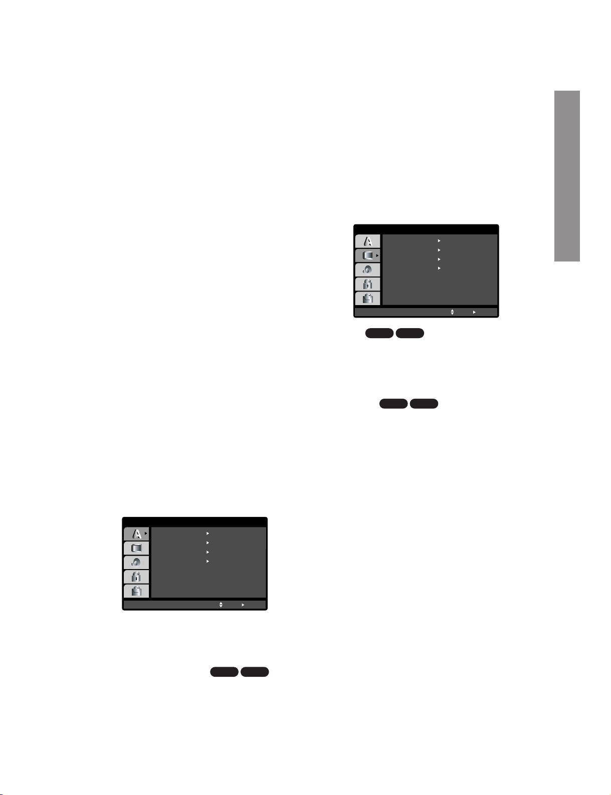
Initial Settings
By using the Setup menu, you can make various
adjustments to items such as picture and sound. You
can also set a language for the subtitles and the
Setup menu, among other things. For details on each
Setup menu item, see pages 21 to 24.
To display and exit the Menu:
Press SETUP to display the menu. A second press of
SETUP will take you back to initial screen.
To go to the next level:
Press wwon the remote control.
To go back to the previous level:
Press W on the remote control.
General Operation
1. Press SETUP.
The Setup menu appears.
2. Use
v / V to select the desired option then press
ww
to move to the second level. The screen shows
the current setting for the selected item, as well
as alternate setting(s).
3. Use
v / V to select the second desired option
then press
ww
to move to the third level.
4.
Use v / V to select the desired setting then press
ENTER/OK to confirm your selection. Some items
require additional steps.
5. Press SETUP or PLAY to exit the Setup menu.
LANGUAGE
Menu Language
Select a language for the Setup menu and on-screen
display.
Disc Audio / Subtitle / Menu
Select the language you prefer for the audio track
(disc audio), subtitles, and the disc menu.
Original: Refers to the original language in which the
disc was recorded.
Other:
To select another language, press number buttons then ENTER/OK to enter the corresponding 4-digit
number according to the language code list in the reference chapter (see p. 44). If you enter the wrong language code, press CLEAR.
DISPLAY
TV Aspect
4:3 :
Select when a standard 4:3 TV is connected.
16:9 Wide: Select when a 16:9 wide TV is
connected.
Display Mode
Display Mode setting works only when the TV Aspect
mode is set to “4:3”.
Letterbox: Displays a wide picture with bands on the
upper and lower portions of the screen.
Panscan:
Automatically displays the wide picture on the
entire screen and cuts off the portions that do not fit.
Progressive Scan
Progressive Scan Video provides the highest quality
pictures with less flickering.
If you are using the Component Video jacks for connection to a TV or monitor that is compatible with a
progressive scan signal, set Progressive Scan to On.
DVD-ADVD-V
DVD-ADVD-V
DVD-ADVD-V
Menu Language
Original
English
Off
Original
Disc Audio
Disc Subtitle
Disc Menu
Move
Select
LANGUAGE
DISPLAY
TV Aspect
Panscan
4 : 3
Display Mode
OffProgressive Scan
Move
Select
TV Output Select RGB
Preparation
Page 28

1-27
To turn on progressive scan:
Connect component out of this unit to the input of
your monitor/television, set your television or monitor
to component Input.
1. Select “Progressive Scan” on the DISPLAY menu
then press
ww
.
2. Select “On” using the
v /V buttons.
3. Press ENTER/OK to confirm your selection.
The confirm menu will appear.
4. When the confirm menu appears on your screen
“Cancel” is highlighted as default. Use the
W but-
ton to highlight “Enter”.
5. Pressing ENTER/OK will set this unit to progressive scan mode.
TV Output Select
Set this unit’s TV Output Select options according to
the TV connection type.
YPbPr: When your TV is connected with the
COMPONENT/PROGRESSIVE SCAN VIDEO OUT
jacks on this unit.
RGB: When your TV is connected with the SCART
(RGB signal) jack.
AUDIO
Each DVD disc has a variety of audio output options.
Set this unit’s AUDIO options according to the type of
audio system you use.
Dolby Digital / DTS / MPEG
Bitstream:
Select “Bitstream” if you connect the
DVD+VCR’s DIGITAL AUDIO OUT jack to an
amplifier or other equipment with a Dolby Digital,
DTS or MPEG decoder.
PCM (for Dolby Digital / MPEG): Select when
connected to a two-channel digital stereo amplifier. DVDs encoded in Dolby Digital or MPEG will
be automatically downmixed to two-channel PCM
audio.
Off (for DTS): If you select “Off”, the DTS signal
is not output through the DIGITAL OUT jack.
Sample Freq. (Frequency)
If your receiver or amplifier is NOT capable of handling 96 kHz signals, select 48 kHz. When this choice
is made, this unit automatically converts any 96 kHz
signals to 48 kHz so your system can decode them.
If your receiver or amplifier is capable of handling 96
kHz signals, select 96 kHz. When this choice is
made, this unit passes each type of signal through
without any further processing.
Check the documentation for your amplifier to verify
its capabilities.
Dynamic Range Control (DRC)
With the DVD format, you can hear a program’s
soundtrack in the most accurate and realistic presentation possible, thanks to digital audio technology.
However, you may wish to compress the dynamic
range of the audio output (the difference between the
loudest sounds and the quietest ones). This allows
you to listen to a movie at a lower volume without losing clarity of sound. Set DRC to On for this effect.
Vocal
Set to On only when a multi-channel karaoke DVD is
playing. The karaoke channels on the disc mix into
normal stereo sound.
DVD-V
DVD-ADVD-V
DVD-ADVD-V
DivX
DVD-ADVD-V
DISPLAY
TV Aspect
TV Output Select
Display Mode
Move
Enter Prev.
OnProgressive Scan
Off
Dolby Digital
Bitstream
PCM
48KHz
On
Bitstream
DTS
MPEG
Sample Freq.
DRC
OnVocal
Move
Select
AUDIO
Page 29
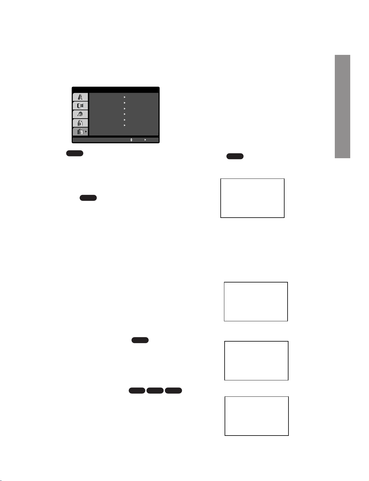
1-28
OTHERS
The PBC, Auto Play, B.L.E., Pluge, DNR and DivX(R)
VOD settings can be changed.
PBC
Set Playback Control (PBC) to On or Off.
On:
Video CDs with PBC are played according to the PBC.
Off: Video CDs with PBC are played the same way as
Audio CDs.
Auto Play
You can set up the DVD+VCR so a DVD disc automatically starts playing whenever the DVD is inserted.
If Auto Play mode is set to On, this DVD+VCR will
search for title that has the longest playback time and
then play back the title automatically.
On: Auto Play function is active.
Off: Auto Play function is not active.
Note:
The Auto Play function may not work for some DVDs.
B.L.E. (Black Level Expansion)
To select the black level of playback pictures. Set your
preference and monitor’s ability.
On: Expanded grey scale. (0 IRE cut off)
Off: Standard grey scale. (7.5 IRE cut off)
Note:
The B.L.E. function works on NTSC system only.
Pluge (Blacker than Black)
For proper adjustment of your television brightness
settings utilizing a commercially available test disc.
On:
Select when you adjust the level of your TV using a commercially available test disc that contains pluge signals.
Off: For normal use.
DNR (Digital Noise Reduction)
You can reduce ambient noise in the picture.
DNR1: Normal level
DNR2: Expanded level.
Off: Off.
Note:
• Actual picture enhancement may vary depending on the
quality of the disc.
• While the DNR2 (expanded level) can provide additional
improvement in the reduction of noise in the video signal,
it may produce undesirable picture artifacts on some
discs. Should this occur, select a more appropriate DNR
level (normal or off).
• Depending on the disc, some picture detail may be lost by
the picture enhancement.
• A DVD audio disc with Dolby Digital or DTS soundtrack
may be played, some DVD audio discs include moving
pictures which may be modified by the above processes.
DivX(R) VOD
You can show the DivX DRM (Digital Right
Management) Registration code for your unit only.
The Registration code is used for VOD (Video-OnDemand) service agent. You can purchase or rental
an encrypt movie file.
Notes:
If you rent the DivX VOD file, it has several options of
viewing limits as show below.
• Display the number which you can watch the file.
• The rental has been expired.
• Display the authorization error.
DivX
VCD1.1VCD2.0
DVD-V
DVD-V
DVD-V
VCD
PBC
Off
Move
Auto Play
OTHERS
On
Select
OnB.L.E.
OnPluge
OffDNR
SelectDivX(R) VOD
DivX(R) Video On Demand
Your registration code is : XXXXXXXX
To learn more visit
www.divx.com/vod
(Done)
View DivX(R) VOD Rental
This rental has 3 view left.
Do you want to use one
of you 3 views now?
(Yes) (No)
Rental Expired
(Done)
Authorization Error
This player is not authorized
to play this video.
(Done)
Preparation
Page 30

1-29
LOCK (Parental Control)
Rating
Some movies contain scenes that may not be suitable for children to view. Many of these discs contain
parental control information that applies to the complete disc or to certain scenes on the disc. Movies
and scenes are rated from 1 to 8, depending on the
country. DVD video discs may or may not respond to
the parental control setting if the Country code of the
disc is set wrongly. Some discs offer more suitable
scenes as an alternative.
The parental control feature allows you to block
access to scenes below the rating you input, thereby
preventing your children from being able to view
material you believe is unsuitable.
1. Select “Rating” on the LOCK menu then
press
w.
2. To access the Rating, Password and Country
Code features, you must input the 4-digit security
code you created. If you have not yet entered a
security code you are prompted to do so.
Input a 4-digit code and press ENTER/OK. Enter it
again and press ENTER/OK to verify. If you make
a mistake before pressing ENTER/OK, press
CLEAR.
3. Select a rating from 1 to 8 using the
v / V but-
tons.
Rating 1-8: Rating one (1) has the most restrictions and rating eight (8) is the least restrictive.
Unlock
If you select unlock, parental control is not active
and the disc plays in full.
Note:
If you set a rating for the player, all disc scenes with the
same rating or lower are played. Higher rated scenes
are not played unless an alternate scene is available on
the disc. The alternative must have the same rating or a
lower one. If no suitable alternative is found, playback
stops.You must enter the 4-digit password or change the
rating level in order to play the disc.
4. Press ENTER/OK to confirm your rating selection,
then press SETUP to exit the menu.
5. Press OPEN/CLOSE (
U) to activate parental
control.
Password (Security Code)
You can enter or change password.
1. Select “Password” on the LOCK menu then press
w.
2. Press ENTER/OK.
3. Follow step 2 as shown left (Rating). “Change” or
“New” is highlighted.
4. Enter the new 4-digit code, then press ENTER/OK.
Input it again to verify.
5. Press SETUP to exit the menu.
If you forget your Security Code
If you forget your security code you can clear it using
the following steps:
1. Press SETUP to display the Setup menu.
2. Input the 6-digit number “210499” and the security
code is cleared.
3. Enter a new code as described above.
Country Code
Enter the code of the country/area whose standards
were used to rate the DVD video disc, based on the
list in the reference chapter (see p. 44).
1. Select “Country Code” on the LOCK menu then
press
w.
2. Follow step 2 as shown left (Rating).
3. Select the first character using
v /V buttons.
4. Press ENTER/OK and select the second charac-
ter using
v /V buttons.
5. Press ENTER/OK to confirm your country code
selection.
DVD-V
DVD-V
LOCK
Rating
New
DE
Unlock
Password
Country Code
Move
Select
Page 31

1-30
Playing a tape
You will only be able to load and eject video cassettes
when your DVD+VCR is plugged into the mains.
Your DVD+VCR may also playback recordings from
NTSC tapes (on PAL TV).
Getting a better picture
When a cassette is inserted and playback started, the
automatic tracking function works to get the best possible picture automatically. If the quality of the recording is
poor, repeatedly press
v or V on the remote control to
manually adjust the tracking until any distortions have
been removed.
1. Make sure that you have correctly connected your
DVD+VCR as described earlier in this book.
Turn on your TV.
Press
I/ to turn on your DVD+VCR.
Insert the video cassette into your DVD+VCR.
The video cassette should have the window side facing
up and the arrow facing away from you.
2. Press PLAY w to start playing your tape.
If you load a video cassette which has had its
record protection tab removed, playback of the
cassette will start automatically.
AUTO TRACKING
Your DVD+VCR will automatically adjust the
tracking to give the best picture quality.
If noise bars appear during playback, adjust the tracking
manually by pressing
PR/TRK+/-.
To resume automatic tracking, press
AUTO TRK.
3. Press PAUSE/STILL II/Rto still a picture.
Press
PAUSE/STILL II/Rrepeatedly to advance
the tape frame by frame.
If you press SLOW R, the picture will be slowed down at
about 1/19 times the normal playback.
Tapes can be paused for up to 5 minutes. After 5 minutes
your DVD+VCR will stop the tape to prevent damaging
the tape or your DVD+VCR. Still picture quality can be
improved slightly by using
v or V.
4. Press PLAY w to continue playing your tape.
Picture search:
During playing back press either REW b or FWD f
to this will enable you to rapidly wind the tape (7 times
normal playback) and see where you are on the tape.
Logic search:
During fast forwarding or rewinding press and hold FWD
or REW respectively. The picture will be played back
at 7 times normal playback speed.
5. Slow motion playback, Shuttle :
During playing back or still picture press W or w.
You can reach the following playback speeds.
(-7xplay, -3xplay, -play, still, 1/19 slow, play, 2xplay,
7xplay)
To switch off the slow motion and shuttle, press the
desired function. During slow motion and shuttle, the
noise bars may appear on the picture according to the
status of tape. If distortions can be seen in the picture,
reduce them with
v or V.
6. Press STOP ■ to end playback.
Press
EJECT UU.
If the end of the tape is reached, your DVD+VCR will
stop playback automatically, rewind, stop, eject the tape
and go to standby.
CM (Commercial Message) Skip:
This feature enables you to skip a commercial break
in a few seconds during tape playback, then resume
normal playback.
While tape is playing press
INSTANT SKIP
on the
remote control to skip commercial (or another
programme material).
Repeatedly press
INSTANT SKIP
to skip:
1 Press 30 seconds
2 Press 60 seconds
3 Press 90 seconds
4 Press 120 seconds
5 Press 150 seconds
6 Press 180 seconds
OPR (Optimum Picture Response)
This feature automatically improves playback picture
quality by adjusting your DVD+VCR to the condition
of the tape.
1. Press
VCR MENU.
2. Press W or w to select OPR.
3. Press
ENTER/OK.
4. Press v or V repeatedly to select: OFF, SOFT or
SHARP.
Please note that you can only set OPR when
playing a tape.
5. Press VCR MENU return to screen.
Operation
REC
i
Pr-12
ACMS
P
SET
R
12
TIME
DATE
SYS-
TEM
OPR
OPR
OSD
ON
OFF
OSD
f
16:9
4:3
NIC
DECO-
DER
+
-
OFF
SOFT
SHARP
Dr.
VCR
Preparation
Page 32

1-31
One-touch Timer Recording (OTR)
Your DVD+VCR allows you to make recordings
using a variety of simple methods:
One-touch Timer Recording (OTR) start
recording immediately for a set period of time or
until the video cassette runs out.
Your DVD+VCR incorporates Long Play (LP)
which enables you to record up to twice the
amount of time on a video cassette. For example
an E-180 will record up to 180 minutes using
Standard Play (SP); using LP you will be able to
record up to 360 minutes. Please note there will be
a slight loss in picture and sound quality when
using LP.
1. Make sure that you have correctly connected your
DVD+VCR as described earlier in this book.
Press I/1 to turn on your DVD+VCR.
2. Insert a video cassette with protection tab into
your DVD+VCR.
The video cassette should have the window side
facing up and the arrow facing away from you.
3. Press
PR/TRK + or - to select the programme
number
you wish to record.
You may also directly select programme number
using the numbered buttons on the remote control.
4. If you wish to record directly from the SCART
sockets or AV jacks, press
INPUT SELECT
repeatedly until the input you wish to record from
is displayed.
AV 1 for recording from EURO AV1 SCART socket
on the rear of your unit.
AV 2 for recording from EURO AV2 SCART socket
on the rear of your unit.
AV 3 for recording from VIDEO IN and AUDIO IN
(Left & Right) jacks on the front of your unit.
5. Press
SP/LP if you wish to record in Long Play or
Standard Play.
SP will produce improved picture and sound quality, however LP will provide twice as much recording time as SP.
6. Press
REC/OTR on the remote to start recording.
RECORD will appear on the TV screen.
Press
REC on your unit or press REC/OTR on the
remote several times. Each successive press will
increase the record time by 30 minutes until you
reach a maximum of 9 hours.
7. Press PAUSE/STILL II/Rto avoid recording
unwanted scenes.
Press
PAUSE/STILL II/Rto continue recording.
Tapes can be paused for up to 5 minutes; RECP
will be displayed briefly when a tape is paused.
After 5 minutes your DVD+VCR will stop recording
to prevent damaging the tape or your DVD+VCR.
8. Press
STOP ■ to end recording.
Press
EJECT UU.
EJECT will appear on the TV screen for a few
seconds.
Notes:
• If you do not wish to record on a tape (this can
happen quite easily by accident!) remove the protection tab on the back edge of the video cassette.
• It is possible to record on a video cassette with the
record protection tab removed by covering the hole
with self adhesive tape.
• Remember you can record one programme while
watching another by starting your instant recording,
press TV/VCR to select TV mode and then selecting a different channel on your TV.
Page 33

1-32
Timer recording using On
Screen Display
You may set up to seven timer record events
within one month of the current date.
Note:
Before setting the timer make sure that you have set the
DVD+VCR clock correctly and you know which stations you
have tuned TV stations on your DVD+VCR.
1. Insert a video cassette with protection tab into
your DVD+VCR.
The video cassette should have the window side
facing up and the arrow facing away from you.
2. Press
VCR MENU.
Press
W or w to select REC.
Press
ENTER/OK.
3. Press
ENTER/OK to start setting the timer record
event.
If all timer record events are full press
v or V to
select the event that you wish to remove and
replace.
Press
W to delete the event.
4. Press the numbered buttons to enter the station
that you wish to record.
When selecting stations 1 - 9, press 0 first, then
the channel number; for example Stations 3 - 03.
You may also select Channels by pressing
v or
V. Once selected press W.
If you wish to record from AUDIO IN (L/R) and
VIDEO IN on the front or from the EURO SCART
sockets on the back of your unit, press INPUT
SELECT to select for correct display (AV1, AV2
or AV3).
5. Press the
numbered buttons to enter the date of
the programme.
If you press
ENTER/OK before entering the date
you may select one of the following automated
recording features. Press
W or w to select, then
press
ENTER/OK to confirm.
DLY To record every day (except Saturday and
Sunday) at the same time.
SU~SA To record at the same time every week.
6. Press the numbered buttons to enter the record-
ing start and end times of the programme that you
wish to record.
Please note your DVD+VCR uses a 24 hour
clock. e.g. 1pm will be displayed as 13:00.
You may also select the start and end times by
using
v or V.
7. Press
w and press v or V to switch VPS/PDC
on or off.
Press
w to select the recording speed.
Press
v or V to select the desired tape speed
(SP, IP, or LP).
IP mode determines how much tape is left and
switches speed from SP to LP, if necessary, to
complete recording the program. IP mode is not
selected when VPS/PDC is ON.
PR DATE
T I M E
- - - - SP
- - - - SP
- - - - SP
- - - - SP
- - - - SP
- - - - SP
PR-01 16
- - - - - - - -~::
- - - - - - - -~::
- - - - - - - -~::
- - - - - - - -~::
- - - - - - - -~::
- - - - - - - -~::
- - - - - - - -~::
SP
i
OK
DLY SU MO TU WE TH FR SA
PR
DATE
T I M E
- - - -
16
SP
- - - -
SP
- - - -
SP
- - - -
SP
- - - -
SP
- - - -
SP
PR-01
- - - - - - - -~::
19 00 20 00~::
- - - - - - - -~::
- - - - - - - -~::
- - - - - - - -~::
- - - - - - - -~::
- - - - - - - -~::
SP
i
PR
DATE
T I M E
- - - -
16
SP
- - - - SP
- - - - SP
- - - - SP
- - - - SP
- - - - SP
PR-01
- - - - - - - -~::
19 00 20 00~::
- - - - - - - -~::
- - - - - - - -~::
- - - - - - - -~::
- - - - - - - -~::
- - - - - - - -~::
i
SP
PR DATE
T I M E
- - - -
- SP
- - - - SP
- - - - SP
- - - - SP
- - - - SP
- - - - SP
PR-01
- - - - - - - -~::
- - - - - - - -~::
- - - - - - - -~::
- - - - - - - -~::
- - - - - - - -~::
- - - - - - - -~::
- - - - - - - -~::
SP
i
PR DATE
T I M E
- - - -
- SP
- - - - SP
- - - - SP
- - - - SP
- - - - SP
- - - - SP
- - - - - - - -~::
- - - - - - - -~::
- - - - - - - -~::
- - - - - - - -~::
- - - - - - - -~::
- - - - - - - -~::
- - - - - - - -~::
SP
i
PR-01
Operation
Page 34

1-33
8. Press VCR MENU to set another timer record
event and follow steps 3 to 7.
Check that the timer event details are correct.
Press
VCR MENU twice.
If
PLEASE CHECK is displayed, you have
entered incorrectly and will need to re-enter the
data.
Press
I/ to switch your DVD+VCR to Timer
Standby mode.
The timer symbol ( ) will appear in the display
window while your DVD+VCR waits to make the
recording.
9. Press
STOP (■) to end timer recording.
Notes:
• During timer recording standby mode, the DVD and
VCR mode cannot be operated. To use the
DVD+VCR, press
I/ . After you use the DVD or
VCR, press I/ again to put the VCR into timer
recording standby mode.
• If at a later date you wish to delete or change any
of the settings in timer event memory you may do
so without having to enter all the timer event information again. Simply display the timer event
screen. Use
v or V to select the event that you
wish to
delete or change.
Press
W to delete the event...or
Press
ENTER/OK to change; then press W or w to
select; Station, Date, Start and End times and LP.
Press
v or V to enter the correct information.
• If Timer record events Overlap...
Make sure that the preset times of the timer recording events do not overlap. If they do, the earlier programme will always be given priority.
Example:
Programme 1 is programmed to start at 16:00 and
end at 17:00.
Programme 2 is programmed to start at 16:30 and
end at 17:30.
(In this case, Programme 1 will be recorded in its
entirety, but only the last 30 minutes of Programme
2 will be recorded.)
• To watch a DVD while performing a timer recording,
press
TV/VCR to select VCR mode. Then press
DVD to view the DVD deck output source on the TV
screen.
• Video Programme System (VPS)
The Video Programme System (VPS) ensures that
the TV programmes that you have programmed for
timer recording will be recorded exactly from their
beginning to end, even if the actual broadcasting
time differs from the scheduled time due to delayed
start, or if the programme is extended beyond its
scheduled time. Also, if a programme is interrupted,
for example, if a news flash is inserted, the recording will also be interrupted automatically and
resumed when the programme continues.
The VPS signal is broadcast by the TV station and
this controls the timer in the video recorder.
VPS should be set ON for all timer recordings from
TV stations broadcasting these signals. It should be
set OFF for all timer recordings from TV stations
that are not broadcasting these signals.
*** The similar system PDC, which is used in the
time being in the Netherlands, can also be used
with your new video recorder.
Page 35

1-34
SHOWVIEW Programming
SHOWVIEW greatly simplifies entering the date,
channel, start and end times of a Timer
Recording by simply entering a S
HOWVIEW
Code. SHOWVIEW Codes are published in most
TV guide magazines; they can vary one to nine
numbers in length.
S
HOWVIEW is a registered trademark of Gemstar
Development Corporation.
The S
HOWVIEW system is manufactured under
licence from Gemstar Development Corporation.
1. Make sure that TV channels have been tuned and
stored in correct
SHOWVIEW order.
Insert a video cassette with protection tab into
your DVD+VCR.
2. Press
SHOWVIEW.
3. Press
D or E to select the recording type.
ONCE: To record once.
DAILY: To record every day (except Saturday and
Sunday) at the same time.
WEEKLY: To record at the same time every week.
4. Press the
numbered buttons to enter the
SHOWVIEW Code of the TV programme that you
wish to record.
If you make a mistake press
F then enter the
revised number.
5. Press
ENTER/OK.
If
PLEASE CHECK is displayed it means that you
have entered the wrong S
HOWVIEW number,
entered the S
HOWVIEW number correctly.
If “
- -” is displayed, you have to enter the pro-
gramme number of the station, you want to record
from.
6. Press
F or G to select the settings that you wish to
revise. (PR, DATE, TIME, VPS/PDC and SP).
Press
D or E to enter the correct information.
7. Press
G and press D or E to switch VPS/PDC on
or off. Press
G to select the recording speed.
Press
D or E to select the desired tape speed (SP,
IP, or LP).
Notes:
• IP mode determines how much tape is left and
switches speed from SP to LP, if necessary, to
complete recording the program.
• IP mode is not selected when VPS/PDC is ON.
Check that the timer event details are correct.
• If you wish to record from AUDIO IN and VIDEO IN
on the front or from either of the EURO SCART
sockets on the back of DVD+VCR, press
INPUT
SELECT to select for correct display (AV1, AV2 or
AV3).
• If you want to make another S
HOWVIEW recording
repeat stages 3 - 7 by pressing SHOWVIEW twice.
8. Press
VCR MENU twice to return to TV Picture.
If
PLEASE CHECK is displayed, you have entered
incorrect information and will need to re-enter the
data.
Press
I/ to switch your DVD+VCR power off
mode. will appear in the video recorder’s display while your DVD+VCR waits to make the
recording. To watch a DVD+VCR during timer
recording standby mode, press
+/1 and switch
DVD+VCR to DVD mode.
ONCE
OK
i
0~9,
SHOWVIEW NO.
- - - - - - - - -
REC
ONCE
OK
i
0~9,
246876543
REC
PR DATE TIME
- - - -
SP
- - - -
SP
- - - -
SP
- - - -
SP
- - - -
SP
- - - -
SP
- - - - - - - -~::
- - - - - - - -~::
- - - - - - - -~::
- - - - - - - -~::
- - - - - - - -~::
- - - - - - - -~::
10
ARD 12
SP
11 11 55~::
i
PR DATE TIME
- - - -
SP
- - - -
SP
- - - -
SP
- - - -
SP
- - - -
SP
- - - -
SP
- - - - - - - -~::
- - - - - - - -~::
- - - - - - - -~::
- - - - - - - -~::
- - - - - - - -~::
- - - - - - - -~::
10
ARD 12
SP
11 11 55~::
i
PR DATE TIME
- - - -
SP
- - - -
SP
- - - -
SP
- - - -
SP
- - - -
SP
- - - -
SP
- - - - - - - -~::
- - - - - - - -~::
- - - - - - - -~::
- - - - - - - -~::
- - - - - - - -~::
- - - - - - - -~::
10
ARD
12
SP
11 11 55~::
i
Operation
Page 36

1-35
Playing a DVD or Video CD
Playback Setup
1. Turn on the TV and select the video input source
connected to the DVD+VCR.
2. Turn on the audio system (if applicable) and
select the input source connected to the
DVD+VCR.
3. Press OPEN/CLOSE (
U) to open the disc tray
and load your chosen disc in the tray, with the
playback side down.
4. Press OPEN/CLOSE (
U) to close the tray.
Playback starts automatically. If playback does not
start, press PLAY (
G).
In some cases, the disc menu might appear
instead.
5. To stop the playback, press STOP
■.
The unit records the stopped point, depending on the
disc. “
II■” appears on the screen briefly. Press PLAY
to resume playback (from the scene point). If you press
STOP
■ again or unload the disc (“■” appears on the
screen.), the unit will clear the stopped point.
Press
OPEN/CLOSE U to remove the disc.
Press
OPEN/CLOSE U to close disc tray or press I/
, the disc tray closes automatically and unit turns off.
If a menu screen is displayed
The menu screen may be displayed first after loading
a DVD or Video CD which offer a menu.
Use the
FG v V buttons to select the
title/chapter you want to view, then press
ENTER/OK to start. Press TOP MENU or MENU
to return to the menu screen.
Use the
FG v V buttons to select an option
you want, then press ENTER/OK to view the
option.
Use the number buttons to select the track you
want to view and press RETURN to return to the
menu screen. Menu settings and operating procedures may differ. Follow the instructions on each
menu screen. You also may set PBC to Off (See
“PBC” on page 23).
Notes:
• If parental control is set and the disc is not within
the rating settings you must input the password.
(See “LOCK” on page 24.)
• DVDs may have a region code.Your player will not
play discs that have a region code different from
your player. The region code for this player is 2
(two).
General Features
Notes:
Unless stated otherwise, all operations described use
the remote control. Some features may also be available on the Setup menu.
Moving to another TITLE/GROUP
When a disc has more than one title/group, you can
move to another title/group. Press DISPLAY, then the
appropriate number (0-9) or use
b / B to move
to another title/group.
Moving to another CHAPTER/TRACK
When a title on a disc has more than one chapter or
a disc has more than one track, you can move to
another chapter/track as follows:
• Press SKIP
F or B briefly during playback
to select the next chapter/track or to return to the
beginning of the current chapter/track.
• Press SKIP
B twice in quick successions to
step back to the previous chapter/track.
• To go directly to any chapter during DVD playback, press DISPLAY and press
v / V to select
the chapter/track icon. Then, input the
chapter/track number or use
F / G.
Search
1. Press REW b or FWD f during playback.
2. Press REW
b or FWD f repeatedly to select
the required speed.
DVD, DivX disc; X2, X4, X16 or X100
Video CD; X2, X4 or X8
3. To exit SEARCH mode, press PLAY (
G).
Note:
When using a DVD audio disc that includes pictures,
this operation may be permitted in some picture
segments.
Changing the Audio Channel
Press AUDIO repeatedly during playback to hear a
different audio channel (STEREO, LEFT or RIGHT).
VCD
DivX
VCD
DVD-ADVD-V
DivXVCD
DVD-ADVD-V
DVD-ADVD-V
VCD
DVD-A
DVD-V
Page 37

1-36
Still Picture and Frame-by-Frame Playback
1. Press PAUSE/STEP (II) during playback. Advance
the picture frame-by-frame by pressing
PAUSE/STEP (II) repeatedly.
2. To exit still motion mode, press PLAY.
Note:
When using a DVD audio disc that includes pictures,
this operation may be permitted in some picture
segments.
Slow Motion
1. Press SLOW R during playback or still mode.
The player will enter SLOW mode.
2. Use REW
b or FWD f (or SLOW R) to
select the required speed:
L 1/16, L 1/8, L
1/4, or L 1/2 (reverse), or R 1/16, R 1/8, R 1/4,
or
R 1/2 (forward).
With a DivX Disc and Video CD, the Slow speed
changes:
R 1/16, R 1/8, R 1/4 or R 1/2 (for-
ward).
3. To exit Slow Motion mode, press PLAY (
G).
Note:
Slow motion playback in reverse is not possible with
Video CDs and DivX Discs..
One Touch Replay
Press INSTANT REPLAY during playback and the
disc will reverse picture search through 10 seconds of
playback. And then the playback will start from the
point again.
Random
1. Press RANDOM during playback. The unit automatically begins random playback and RANDOM
appears on the TV screen.
2. Press RANDOM again to normal.
Tip:
By pressing SKIP B or F during random playback,
the unit selects another title (track) and resumes Random
playback.
Note:
On a Video CD with PBC, You must set PBC to Off on the
setup menu to use the random function
(See “PBC” on page 23).
Repeat A-B
To repeat a sequence.
1. Press A-B at your chosen starting point. “ A*”
appears briefly on the TV screen.
2. Press A-B again at your chosen end point.
“A B” appears briefly on the TV screen and the
repeat sequence begins.
3. Press A-B again to cancel.
Repeat
You can repeat a title/chapter/all/track/group on a
disc.
Press REPEAT during playback to select a desired
repeat mode.
DVD Video Discs - Repeat Chapter/Title/Off
• Chapter: repeats the current chapter.
• Title: repeats the current title.
• Off : does not play repeatedly.
Video CDs, DivX discs - Repeat Track/All/Off
• Track : repeats the current track
• All : repeats all the tracks on a disc.
• Off : does not play repeatedly.
DVD Audio Discs - Repeat Track/Group/Off
• Track: repeats the current track.
• Group: repeats the current Group.
• Off : does not play repeatedly.
Note:
• On a Video CD with PBC, you must set PBC to Off on the
setup menu to use the repeat function (See “PBC” on
page 23).
• If you press SKIP (
) once during Repeat Chapter (Track)
playback, the repeat playback cancels.
3D Surround
To produce a 3D surround effect that simulates multichannel audio from two stereo speakers (instead of
the five+ speakers normally required for multi-channel
audio from a home theater system).
1. Press DISPLAY during playback.
2. Use
v or V to select the sound option.
The sound option will be highlighted.
3. Use F or G to to select “3D SUR”.
To turn off the 3D Surround effect, select
“Normal”.
DivXVCD
DVD-ADVD-V
DivXVCD
DVD-ADVD-V
DivXVCD
DVD-ADVD-V
Karaoke DVDVCD
DVD-ADVD-V
DivXVCD
DVD-ADVD-V
DivXVCD
DVD-ADVD-V
Operation
Page 38

1-37
Time Search
To start playing at any chosen time on the disc:
1. Press DISPLAY during playback. The time search
box shows the elapsed playing time.
2. Press
v / V to select the time clock icon and
“-:--:--” appears.
3. Input the required start time in hours, minutes,
and seconds from left to right. If you enter the
wrong numbers, press CLEAR to remove the
numbers you entered. Then input the correct numbers.
4. Press ENTER/OK to confirm. Playback starts from
the selected time.
Changing Video Mode
• With certain discs, the playback picture may be
flickering or Dot Crawl is shown on straight lines.
That means Vertical interpolation or De-interlace is
not perfectly matched with the disc. In this case,
the picture quality may be improved by changing
the video mode.
• To change the video mode, press and hold
DISPLAY about 3 seconds during disc playback.
The new video mode number selected is displayed
on the TV screen. Check whether the video quality
has improved. If not, repeat the above procedure
until picture quality is improved.
• Video mode sequence:
MODE1→MODE2→MODE3→MODE1
• If you turn off the power, the video mode will return
to initial default state (MODE1).
Detailed Description of each Video Mode
MODE1 : The source material of the DVD video (film mate-
rial or video material) is determined from disc
information.
MODE2 : Suitable for playing film based content or video
based material recorded by the progressive scan
method.
MODE3 : Suitable for playing video based content with
comparatively little motion.
Note:
The video mode setting only works when the
Progressive Scan option is set to “On” in the Setup
menu.
Zoom
Use zoom to enlarge the video image.
1. Press ZOOM during playback or still playback to
activate the Zoom function. The square frame
appears briefly in the right bottom of the picture.
2. Each press of the ZOOM button changes the TV
screen in the sequence: 100% size → 400% size
→ 1600% size → screen fit mode → 100% size
Screen fit mode:
You can change the way the image appears on
the screen when you’re playing a DVD movie.
Press
v/V to select between Normal, Enhanced,
and Maximum.
3. Use the
FGvVbuttons to move through the
zoomed picture.
4. To resume normal playback, press ZOOM repeatedly or CLEAR button.
Notes:
• Zoom may not work on some DVDs.
• Screen fit mode is available for playing the DVD disc, VR
disc and movie file.
Marker Search
To enter a Marker
You can start playback from up to nine memorized
points. To enter a marker, press MARKER at the
desired point on the disc. The Marker icon appears
on the TV screen briefly. Repeat to enter up to nine
markers.
To Recall or Clear a Marked Scene
1. During disc playback, press SEARCH. The marker
search menu appears on the screen.
2. Within 10 seconds, press
F / G to select a marker
number that you want to recall or clear.
3. Press ENTER/OK and playback starts from the
marked scene. Or, Press CLEAR and the marker
number is erased from the list.
4. You can play any marker by inputting its number
on the marker search menu.
Screen Saver
The screen saver appears when you leave the
DVD+VCR in Stop mode for about five minutes.
DivXVCD
DVD-ADVD-V
DivXVCD
DVD-ADVD-V
DVD-ADVD-V
DivXVCD
DVD-V
Page 39

1-38
Special DVD Features
Checking the contents of DVD discs: Menus
DVDs may offer menus that allow you to access special features. To use the disc menu, press MENU.
Input the corresponding number or use the
FGvV
buttons to highlight your selection. Then press
ENTER/OK.
Title Menu
1. Press TOP MENU. If the current title has a menu,
the menu appears on the screen. Otherwise, the
disc menu may appear.
2. The menu offers features such as camera angles,
spoken language and subtitle options, and chapters for the title.
3. Press TOP MENU to exit.
Disc Menu
Press MENU and the disc menu is displayed.
Press MENU again to exit.
Camera Angle
If the disc contains scenes recorded at different camera angles, you can change to a different camera
angle during playback. Press ANGLE repeatedly during playback to select a desired angle. Note that the
number of the current angle appears on the display.
Tip:
The angle indicator will blink on the TV screen during
scenes recorded at different angles as an indication that
angle switching is possible.
Changing the Audio Language
Press AUDIO repeatedly during playback to hear a
different audio language or audio track.
With DVD-RW discs recorded in VR mode that have
both a main and a Bilingual audio channel, you can
switch between Main (L), Bilingual (R), or a mix of
both (Main + Bilingual) by pressing AUDIO.
Subtitles
Press SUBTITLE repeatedly during playback to see
the different subtitle languages.
Notes:
• This unit can only read subtitle with “.smi”, “.srt” or “.sub”
extension only.
• If there is no information or the unit can not read subtitle
of the DivX file, even if it has subtitle file, “ 1 ” etc. are displayed.
DivX
DVD-V
DivX
DVD-ADVD-V
DVD-ADVD-V
DVD-ADVD-V
DVD-ADVD-V
Operation
Page 40

1-39
DVD Audio Discs
DVD Audio is a new disc format building on the success of DVD to provide high quality, uncompressed,
multi-channel audio for a new experience in audio
quality. A DVD Audio disc can be identified by the
DVD audio logo on the disc jacket or on the disc
itself.
DVD Audio can provide higher quality stereo than
Audio CDs with a sampling rate of up to 192kHz
(compared to 44.1kHz for CDs). DVD Audio digital
sound can be delivered with up to 24 bits of data
(compared to 16 bits for a standard CD).
A typical DVD Audio disc contains up to seven times
the data capacity of a CD.This additional space is
used for music, either Advanced Resolution multichannel sound quality that is closer to the artist’s
master recording or for longer recordings. Many DVD
Audio discs contain on-screen text, such as artist
biographies, playlists, or lyrics. Some DVD Audio
discs contain photo galleries or video clips.
Note:
To enjoy maximum sound quality and surround effect
of DVD Audio, you must use the DIGITAL OUT
(OPTICAL or COAXIAL) for your audio connection.
Moving to another GROUP
Some DVD Audio discs divide content into different
groups.Your player enables you to quickly access different groups during playback via the on-screen display.
1. Press DISPLAY during playback or in stop mode.
2. Press
v / V to select Group icon.
3. Press
F / G or the numbered buttons (0-9) to
select a group number.
Note:
Sometimes the author of the disc creates hidden content that can only be accessed by entering a password. If the lock icon appears on the TV screen, enter
the password (sometimes you’ll find it on the disc’s
jacket cover or on a web site). This password control
isn’t dictated by your DVD+VCR — it is a function of
the disc.
Since the authoring of DVD Audio Discs varies, some
of the on-screen display choices might not be available for the disc you’re playing.
Viewing another PAGE
Since DVD Audio discs can hold a lot of content,
there are various ways to see what’s available on the
disc.
1. Press DISPLAY during playback.
2. Press
v / V to select Page icon.
3. Press
F / G to select a page number.
What appears on the screen will vary from disc to
disc because the information available depends
upon the way the disc was created.
Note:
Since the authoring of DVD Audio Discs varies, some
of the on-screen display choices might not be available for the disc you’re playing.
1 / 2
1 / 21
Page 41

1-40
Playing an Audio CD or MP3/WMA
Disc
The DVD+VCR can play MP3/WMA formatted recordings on CD-ROM, CD-R, or CD-RW discs.
Audio CD
Once you insert an audio CD a menu appears on the
TV screen. Press
v / V to select a track then press
PLAY (
w) or ENTER/OK and playback starts.
MP3 / WMA
1. Press v / V to select a folder, and press
ENTER/OK to see the folder contents.
2. Press
v / V to select a track then press PLAY
(
w) or ENTER/OK. Playback starts.
ID3 TAG
• When playing a file containing information such as track
titles, you can see the information by pressing DISPLAY.
[ Title, Artist, Album, Year, Comment ]
• If there is no information, “No ID3 TAG” appear on the
menu screen.
Tips:
• If you are in a file list on the “MUSIC” menu and want to
return to the Folder list, use the
v / V to highlight
and press ENTER/OK.
• Press MENU to move to the next page.
• On a CD with MP3/WMA and JPEG you can switch
MP3/WMA and JPEG. Press TOP MENU and “MUSIC” or
“PHOTO” word on top of the menu is highlighted.
MP3 / WMA disc compatibility with this player is
limited as follows:
• Sampling frequency: within 8 - 48 kHz (MP3),
within 32 - 48kHz (WMA)
• Bit rate: within 8 - 320kbps (MP3),
32 - 192kbps (WMA)
• The player cannot read an MP3/WMA file that
has a file extension other than “.mp3” / “.wma”.
• CD-R physical format should be ISO 9660
• If you record MP3 / WMA files using software that
cannot create a file system (eg. Direct-CD) it is
impossible to playback MP3 / WMA files. We recommend that you use Easy-CD Creator, which
creates an ISO 9660 file system.
• File names should have a maximum of 8 letters
and must incorporate an .mp3 or .wma extension.
• They should not contain special letters such as /
? * : “ < > l etc.
• The total number of files on the disc should be
less than 650.
This DVD+VCR requires discs and recordings to
meet certain technical standards in order to
achieve optimal playback quality. Pre-recorded
DVDs are automatically set to these standards.
There are many different types of recordable disc
formats (including CD-R containing MP3 or WMA
files) and these require certain pre-existing conditions (see above) to ensure compatible playback.
Customers should note that permission is
required in order to download MP3 / WMA files
and music from the Internet. Our company has
no right to grant such permission. Permission
should always be sought from the copyright
owner.
Microsoft, Windows Media, and
the Windows Logo are trademarks
or registered trademarks of
Microsoft Corporation in both the
United States and other countries
Operation
Operation
AUDIO CD
1:01:47
1 / 12
TRACK01
TRACK02
TRACK03
TRACK04
TRACK05
TRACK06
TRACK07
TRACK08
1-Music1
1-Music1
2-Music2
2-Music2
3-Music3
3-Music3
4-Music4
4-Music4
5-Music5
5-Music5
6-Music6
6-Music6
7-Music7
7-Music7
List
MUSIC
0:00:00
List
List
InfoDISPLAY
1 / 104
Program
Clear All
EditPROGRAM
Program
Clear All
EditPROGRAM
Page 42

1-41
Audio CD and MP3 / WMA Disc
Features
Pause
1. Press PAUSE/STEP II/Rduring playback.
2. To return to playback, press PLAY
w or press
PAUSE/STEP
II/Ragain.
Moving to another Track
1. Press SKIP (B or F) briefly during playback
to go to the next track or to return to the beginning of the current track.
2. Press SKIP
B twice in quick successions to go
back to the previous track.
3. You can play any track by inputting its number.
Repeat Track/All/Off
You can play a track/all on a disc.
1. Press REPEAT when playing a disc. The repeat
icon appears.
2. Press REPEAT to select a desired repeat mode.
• Track: repeats the current track.
• All: repeats all the tracks on a disc.
• Off(No display): does not play repeatedly.
Note:
If you press SKIP (F) once during Repeat Track playback, the repeat playback will be cancelled.
Search
1. Press REW b or FWD f during playback.
2. Press REW
b or FWD f repeatedly to select
the required speed: X2, X4, X8 backward or forward.
3. To exit SEARCH mode, press PLAY
w.
Random
1. Press RANDOM during playback. Random
Playback begins immediately and RANDOM
appears on the menu screen.
2. To return to normal playback, press RANDOM
repeatedly until RANDOM disappears from the
menu screen.
Tip:
By pressing SKIP B or F during random playback,
the unit selects another track and resumes random playback.
Repeat A-B
1. To repeat a sequence during disc playback press
A-B at your chosen starting point. The Repeat
icon and “A” appear on the menu screen.
2. Press A-B again at your chosen end point. The
Repeat icon and “A-B” appear on the menu
screen, and the sequence begins to play repeatedly.
3. To exit the sequence and return to normal play,
press A-B again. The Repeat icon disappears
from the menu screen.
3D Surround
To produce a 3D surround effect that simulates multichannel audio from two stereo speakers (instead of
the five+ speakers normally required for multi-channel
audio from a home theater system).
1. Press AUDIO during playback.
“3D SUR.” appears on the menu screen.
2. To return to normal playback, press AUDIO
repeatedly until “3D SUR.” disappears from the
menu screen.
CD
CD
WMA
MP3CD
WMA
MP3CD
WMA
MP3CD
WMA
MP3CD
WMA
MP3CD
Page 43

1-42
Programmed Playback
The program function enables you to store your
favourite tracks from any disc in the player memory. A
program can contain 30 tracks.
1. Insert a disc.
Audio CD or MP3/WMA Discs:
AUDIO CD or MUSIC menu appears.
2. Press PROGRAM.
The mark will appear to the right of the word
“Program” on the right side of the menu screen.
Note:
Press PROGRAM again, the mark will disappear to exit
the Program Edit mode.
Audio CD Menu MP3/WMA Menu
Video CD: Press PROGRAM while playback is
stopped. The program menu appears. Press PROGRAM again to exit the menu.
Note:
On a Video CD with PBC, you must set PBC to Off on the
setup menu to use the programmed playback (See “PBC” on
page 23).
Video CD Menu
3. Select a track on the “List”, then press ENTER/OK
to place the selected track on the “Program” list.
Repeat to place additional tracks on the list.
4. Press
w.
Select the track you want to start playing on the
“Program” list.
5. Press PLAY (
w) or ENTER/OK to start. Playback
begins in the order in which you programmed the
tracks. Playback stops after all of the tracks on the
“Program” list have played once.
6.
To resume normal playback from programmed playback, select a track of AUDIO
CD (or MUSIC) list and then press
PLAY (w).
Repeat Programmed Tracks
1. Press REPEAT when playing a disc. The repeat
icon appears.
2. Press REPEAT to select a desired repeat mode.
• TRACK: repeats the current track
• ALL: repeats all the tracks on programmed list.
• Off(No display): does not play repeatedly.
Note:
If you press F once during Repeat Track playback, the
repeat playback will be cancelled.
Erasing a Track from “Program” List
1. Use vVwto select the track that you wish to
erase from the Program list.
2. Press CLEAR. Repeat to erase additional tracks
on the list.
Erasing the Complete Program List
1. Press w to move to the “Program” list.
2. Use
v / V to select “Clear All”, then press
ENTER/OK.
Note:
The programs are also cleared when the disc is removed.
Operation
E
AUDIO CD
1:01:47
1 / 12
TRACK01
TRACK02
TRACK03
TRACK04
TRACK05
TRACK06
TRACK07
TRACK08
List
TRACK01
TRACK02
TRACK03
TRACK04
TRACK05
TRACK06
Program
Clear All
EditPROGRAM
E
MUSIC
0:00:00
1-Music1
1-Music1
2-Music2
2-Music2
3-Music3
3-Music3
4-Music4
4-Music4
5-Music5
5-Music5
6-Music6
6-Music6
7-Music7
7-Music7
1 / 104
List
List
1-Music1
2-Music2
3-Music3
4-Music4
5-Music5
6-Music6
EditPROGRAMInfoDISPLAY
Program
Clear All
E
VIDEO CD
TRACK01
TRACK02
TRACK03
TRACK04
List
TRACK1
TRACK2
TRACK3
TRACK4
Program
E
Clear All
Page 44

1-43
Viewing a JPEG Disc
Using this DVD+VCR you can view JPEG files.
1. Insert a disc and close the tray. The PHOTO menu
appears on the TV screen.
2. Press
v / V to select a folder, and press
ENTER/OK. A list of files in the folder appears. If
you are in a file list and want to return to the pre-
vious Folder list, use the
v / V buttons on the
remote to highlight and press ENTER/OK.
3. If you want to view a particular file, press
v / V to highlight a file and press ENTER/OK or
PLAY.The selected file will appear for viewing.
While viewing a file, you can press STOP to move
to the previous menu (PHOTO menu).
Tip:
• Press MENU to move to the next page.
• There are three Slide Speed options :
>>> (Fast), >> (Normal), and > (Slow).
Use
vVW wto highlight the Speed. Then, use W / w
to select the option you want to use then press
ENTER/OK.
• On a disc with MP3/WMA and JPEG you can switch
MP3/WMA and JPEG. Press TOP MENU and MUSIC or
PHOTO word on top of the menu is highlighted.
• Press RETURN, information of file is hidden.
Slide Show
Use vVW wto highlight the (Slide Show) then
press ENTER/OK.
Still Picture
1. Press PAUSE/STEP II/Rduring slide show.
The player will now go into PAUSE mode.
2. To return to the slide show, press PLAY
w or
press PAUSE/STEP
II/Ragain.
Moving to another File
Press SKIP (B or F) or cursor (W or w) once
while viewing a picture to advance to the next or previous file.
Zoom
Use zoom to enlarge the photo image. (see page 32)
To rotate picture
Press v / V during showing a picture to rotate the
picture clockwise or counter clockwise.
To listen to MP3/WMA music while watching
picture
You can display files while listening to MP3/WMA
music files recorded on the same disc.
1. Insert the disc containing the two types of file in
the player.
2. Press TOP MENU to display PHOTO menu.
3. Press
v / V to select a photo file.
4. Use
w to select icon then press ENTER/OK.
Playback starts. The playback will continue until
STOP is pressed.
Tip:
To listen to only the desired music while watching picture, programmed the desired tracks from the
“MUSIC” menu and then proceed as above
.
JPEG
JPEG
JPEG
JPEG
JPEG
JPEG
JPEG disc compatibility with this player is limited as follows:
• Depending upon the size and number of JPEG
files, it could take a long time for the DVD+VCR
to read the disc’s contents. If you don’t see an
on-screen display after several minutes, some of
the files may be too large — reduce the resolution of the JPEG files to less than 2M pixels as
2760 x 2048 pixels and burn another disc.
• The total number of files and folders on the disc
should be less than 650.
• Some discs may be incompatible due to a different recording format or the condition of disc.
• Ensure that all the selected files have the “.jpg”
extensions when copying into the CD layout.
• If the files have “.jpe” or “.jpeg” extensions,
please rename them as “.jpg” file.
• File names without “.jpg” extension will not be
able to be read by this DVD+VCR. Even though
the files are shown as JPEG image files in
Windows Explorer.
PHOTO
List
JPEG Folder 1
JPEG Folder 2
JPEG Folder 3
JPEG Folder 4
JPEG Folder 5
JPEG Folder 6
JPEG Folder 7
JPEG Folder 8
Preview
>>>
Page 45

1-44
Playing a DVD VR format Disc
This unit will play DVD-R/RW discs recorded using
the DVD-Video format that have been finalized using
a DVD-recorder.
• This unit will play DVD-RW discs recorded using
the Video Recording (VR) format.
1. Insert a disc and close the tray. The DVD-VR
menu appears on the TV screen.
2. Press
v / V to select a track then press PLAY
(
w) or ENTER/OK and playback starts.
3. Press TOP MENU to move to the list menu.
Note:
• Unfinalized DVD-R/RW discs cannot be played in this
player.
• Some DVD-VR disc are made with CPRM data by DVD
RECORDER. Player does not support these kinds of
discs and display the “CHECK DISC”.
What is ‘CPRM’?
CPRM is a copy protection system (with scramble system) only allowing the recording of ‘copy once’ broadcast
programs. CPRM stands for Content Protection for
Recordable Media.
This player is CPRM compatible, which means that you
can record copy-once broadcast programs, but you cannot then make a copy of those recordings. CPRM recordings can only be made on DVD-RW discs formatted in VR
mode, and CPRM recordings can only be played on play-
ers that are specifically compatible with CPRM.
Operation
Page 46

1-45
Playing a DivX Movie Disc
Using this DVD+VCR you can play DivX disc.
1. Insert a disc and close the tray. The MOVIE
menu appears on the TV screen.
2. Press
v / V to select a folder, and press
ENTER/OK. A list of files in the folder
appears. If you are in a file list and want to
return to the Folder list, use the
v / V buttons on the remote to highlight and
press ENTER/OK.
3. If you want to view a particular file, press
v / V to highlight a file and press
ENTER/OK or
PLAY (w).
4. Press STOP (ÁÁ) to exit.
Tip:
• Press MENU to move to the next page.
• On a CD with MP3/WMA, JPEG and MOVIE file, you can
switch MUSIC, PHOTO and MOVIE menu. Press TOP
MENU and MUSIC, PHOTO and MOVIE word on top of
the menu is highlighted.
DivX disc compatibility with this player is limited
as follows:
• Available resolution size of the DivX file is under
720x576 (W x H) pixel.
• The file name of the DivX subtitle is available by
56 characters.
• If there is impossible code to express in the DivX
file, it may be displayed as “ _ ” mark on the display.
• If the number of the screen frame is over 30
per 1 second, this unit may not operate normally.
• If the video and audio structure of recorded
file is not interleaved, either video or audio is
outputted.
• If the file is recorded with GMC, the unit supports only 1-point of the record level.
*
GMC?
GMC is the acronym for Global Motion Compensation. It
is an encoding tool specified in MPEG4 standard. Some
MPEG4 encoders, like DivX or Xvid, have this option.
There are different levels of GMC encoding, usually
called 1-point, 2-point, or 3-point GMC.
Playable DivX file
• “.avi”, “.mpg”, “.mpeg”
Playable Codec format
• “DIVX3.xx “, “DIVX4.xx”, “DIVX5.xx”, “XVID”,
“MP43”, “3IVX”.
Playable Audio format
• “AC3”, “DTS”, “PCM”, “MP3”, “WMA”.
- Sampling frequency: within 8 - 48 kHz (MP3),
within 32 - 48kHz (WMA).
- Bit rate: within 8 - 320kbps (MP3),
32 - 192kbps (WMA)
List
Movie Folder 1
Movie Folder 2
Movie Folder 3
Movie Folder 4
Movie Folder 5
Movie Folder 6
Movie Folder 7
Movie Folder 8
MOVIE
0:00:00
Page 47

1-46
Additional Operation with tape
Hi-Fi Stereo Sound System (NIC)
Your DVD+VCR will record and playback Hi-Fi stereo
sound. In addition it has a stereo NICAM digital
stereo sound decoder. This allows you to record and
playback the sound in several different ways. Video
cassettes recorded on your DVD+VCR will have a
normal mono audio track and two VHS Hi-Fi stereo
audio tracks. These stereo tracks allow you to make
audio recordings in Hi-Fi stereo or bilingual mode
from a TV broadcast, stereo audio system, video disc
or another Hi-Fi VCR.
1. Your DVD+VCR’s NICAM digital sound decoder
allows you to enjoy broadcasts with NICAM
sound, as well as standard stereo, bilingual and
mono sound. The particular type of sound
received or that recorded will be briefly displayed
on the TV screen for a couple of seconds:
STEREO NICAM
Sound is automatically recorded on the Hi-Fi
stereo and mono tracks of the video tape.
BIL NICAM
Both audio channels will be recorded on the Hi-Fi
stereo tracks. The primary language channel (left)
will be recorded on the mono track of the video
tape.
MONO
The sound is recorded on the Hi-Fi tracks and the
mono track of the video tape without any separation.
2. Press AUDIO repeatedly until the desired audio
mode appears.
3. The choice is STEREO, LEFT, RIGHT and
MONO. In BIL NICAM playback the primary language is output on the left channel and the secondary channel is output simultaneously from the
right channel when audio output is set to
STEREO. The primary language will be output
from both channels when the audio setting is
MONO.
Please note that when adjusting the tracking control Hi-Fi stereo sound may revert to MONO.
Note:
When OFF is selected in NIC, only mono sound will
be output.
Blank Search
The Blank Search enables you to locate the end of
any recording. Whenever a recording creates, a blank
content is recorded on the tape.
Press BLANK SEARCH in the stop mode and it
rapidly advanced to find blank content.
To find next blank content, press BLANK SEARCH
again.
On Screen Display (F.OSD)
You may easily display the current time or tape
counter, amount of tape left, day, month, year, day of
week, programme channel, tape speed and operational mode of your DVD+VCR on the TV screen. If a
recording is taking place these On Screen Displays
will not be recorded onto the tape.
1. Press CLK/CNT to display.
Press CLK/CNT repeatedly to cycle through the
display options. The tape counter and amount of
tape left will appear if there is a tape loaded.
2. After 3 seconds the majority of the On Screen
Displays will clear leaving only the clock or tape
counter and the amount of tape left on the screen.
Press CLK/CNT again to remove all displays from
the TV screen.
Note:
It cannot display when F.OSD is OFF.
Tape Counter Memory Stop
The Digital Tape Counter can be displayed on the display window instead of the time by pressing CLK/CNT
on the remote control. The Digital Tape Counter indicates the relative positions of recordings on the tape.
1. Press CLK/CNT.
Press COUNTER RESET to set the counter to
0:00:00.
Press PLAY
w or start recording.
The tape counter will display the actual play time
in hours, minutes and seconds.
2. Press STOP ■ when playback or recording is
complete.
Press REW b.
The tape will rewind and automatically stop when
the counter returns to 0:00:00.
Note:
To rewind to the beginning of the tape, press REW b
again.
Operation
Page 48

1-47
Video Doctor (Self-Diagnosis)
This feature informs you that there is a problem with
your DVD+VCR. These error messages will appear
on the TV screen.
1. Press VCR MENU.
Press
W or w to select Dr.
Press ENTER/OK.
2. Press v or V to check a problem.
HEAD STATUS
• PLEASE CLEAN:
Clean your video heads.
TAPE STATUS
• NOT RECORDABLE:
Insert a tape with its protection tab in place
NO. OF TIMER PROGRAMME
• 2
Shows the number of timer recording.
NEXT TIMER PROGRAMME
• PR-01 26 10:00~11:00 SP
Shows the current status of timer recording.
3. Press VCR MENU to remove the menus from the
TV screen.
Wide Screen Compatibility 16:9
Your DVD+VCR can record and play back wide
screen aspect ratio programmes (16:9). To record a
wide screen format programme successfully the correct type of wide screen signal must be broadcast by
the TV station.
1. Switch on your DVD+VCR.
Press VCR MENU.
Press F or G to select 16:9/4:3.
Press ENTER/OK.
2. Press v/V repeatedly to select: AUTO, 4:3 or
16:9.
AUTO:
Automatically plays back Wide-Screen
programmes as Wide-Screen and Normal
programmes as normal.
4:3
Only for playing back and recording Normal format
recordings (4:3).
16:9:
Only for playing back and recording Wide-Screen format recordings (16:9).
3. Press VCR MENU to remove the menus from the
TV screen.
REC
OK
i
SYS-
Pr-12
ACMS
12
TIME
DATE
Dr.
VCR
Dr.
VCR
TEM
P
SET
R
OSD
ON
OFF
OSD
f
16:9
4:3
OPR
NIC
DECO-
DER
+
-
REC
Pr-12
ACMS
P
SET
R
12
TIME
DATE
SYS-
TEM
OSD
ON
OFF
OSD
f
16:9
4:3
16:9
4:3
Dr.
VCR
OPR
OK
i
NIC
DECO-
DER
+
-
REC
i
Pr-12
ACMS
P
SET
R
12
TIME
DATE
SYS-
TEM
OSD
ON
OFF
OSD
f
16:9
4:3
16:9
4:3
Dr.
VCR
OPR
NIC
DECO-
DER
+
-
AUTO
4:3
16:9
Page 49

1-48
To set the decoder
We have already described, how to connect a
decoder for pay-TV station as DECODER or PREMIERE on page 13-14. For the recording of an
encoded station you do not have to control anything.
You just select the station and wait shortly until the
decoding will start.
1. Press VCR MENU.
The main menu will appear on the TV screen.
Press
F or G to select the DECODER.
Press ENTER/OK.
2. Press D or E to select.
ON: When the decoder is connected to the AV2
socket.
OFF: When another VCR is connected to the AV2
socket.
3. Press VCR MENU to return to a TV picture.
Copying from DVD To VCR
This unit allows you to copy the contents of a DVD to
a VHS tape with a press of the
REC/OTR button.
Note:
If the DVD you are attempting to copy is copy protected, you
may not be able to copy the disc.
1. Insert Disc
Insert the disc you wish to copy in the DVD deck
and close the disc tray.
2. Insert VHS Tape
Insert a blank VHS videotape into the VCR deck.
3. Press DVD so that the DVD indicator lights up.
4. Copy the DVD to VHS Tape
Press the REC
O button on the unit front panel.
• The DVD will go into Play mode and the VCR
will go into Record mode.
• If the DVD disc menu appears, you may need
to press the Play button manually to begin
copying.
5. Stop the Copy Process.
Press STOP
■.
Recording from another video recorder
With this video recorder you can make recordings
from an external source, such as copying from another video recorder or a camcorder.
Note:
In the following description, this video recorder will be one
used for recording and will be referred to as VCR B. The
other appliance will be used for playback and will be referred
to as VCR A.
1. VCR A should be connected to the SCART socket
on the rear panel of your unit or the AV jacks on
the front panel of your unit.
2. Insert the recorded tape into VCR A and a blank
tape into VCR B.
3. To start recording, press the REC O on VCR B
and PLAY
G on VCR A.
4. When you want to finish copying,
press STOP
■ on this video recorder and then
STOP
■ the VCR A.
Video Head Cleaning
Whenever a video cassette is inserted into or ejected
from your DVD+VCR the video head is automatically
cleaned.
This should mean that additional head cleaning
should not be necessary.
However, dirt accumulating on the head after a long
period of time can cause the playback picture to
become blurred or broken up. High quality video cassette tapes will not normally deposit dirt onto the
video head, but old or damaged tapes might.
Operation
Page 50

1-49
Reference
Country Code
Afghanistan AF
Argentina AR
Australia AU
Austria AT
Belgium BE
Bhutan BT
Bolivia BO
Brazil BR
Cambodia KH
Canada CA
Chile CL
China CN
Colombia CO
Congo CG
Costa Rica CR
Croatia HR
Czech Republic CZ
Denmark DK
Ecuador EC
Egypt EG
El Salvador SV
Country Code
Ethiopia ET
Fiji FJ
Finland FI
France FR
Germany DE
Great Britain GB
Greece GR
Greenland GL
Islands HM
Hong Kong HK
Hungary HU
India IN
Indonesia ID
Israel IL
Italy IT
Jamaica JM
Japan JP
Kenya KE
Kuwait KW
Libya LY
Luxembourg LU
Country Code
Malaysia MY
Maldives MV
Mexico MX
Monaco MC
Mongolia MN
Morocco MA
Nepal NP
Netherlands NL
Netherlands Antilles AN
New Zealand NZ
Nigeria NG
Norway NO
Oman OM
Pakistan PK
Panama PA
Paraguay PY
Philippines PH
Poland PL
Portugal PT
Romania RO
Russian Federation RU
Country Code
Saudi Arabia SA
Senegal SN
Singapore SG
Slovak Republic SK
Slovenia SI
South Africa ZA
South Korea KR
Spain ES
Sri Lanka LK
Sweden SE
Switzerland CH
Taiwan TW
Thailand TH
Tu r ke y T R
Uganda UG
Ukraine UA
United States US
Uruguay UY
Uzbekistan UZ
Vietnam VN
Zimbabwe ZW
Country Codes
Choose a country code from this list.
Language Code
Abkhazian 6566
Afar 6565
Afrikaans 6570
Albanian 8381
Ameharic 6577
Arabic 6582
Armenian 7289
Assamese 6583
Aymara 6588
Azerbaijani 6590
Bashkir 6665
Basque 6985
Bengali; Bangla 6678
Bhutani 6890
Bihari 6672
Breton 6682
Bulgarian 6671
Burmese 7789
Byelorussian 6669
Cambodian 7577
Catalan 6765
Chinese 9072
Corsican 6779
Croatian 7282
Czech 6783
Danish 6865
Dutch 7876
English 6978
Esperanto 6979
Estonian 6984
Faroese 7079
Language Code
Fiji 7074
Finnish 7073
French 7082
Frisian 7089
Galician 7176
Georgian 7565
German 6869
Greek 6976
Greenlandic 7576
Guarani 7178
Gujarati 7185
Hausa 7265
Hebrew 7387
Hindi 7273
Hungarian 7285
Icelandic 7383
Indonesian 7378
Interlingua 7365
Irish 7165
Italian 7384
Japanese 7465
Javanese 7487
Kannada 7578
Kashmiri 7583
Kazakh 7575
Kirghiz 7589
Korean 7579
Kurdish 7585
Laothian 7679
Latin 7665
Latvian, Lettish 7686
Language Code
Lingala 7678
Lithuanian 7684
Macedonian 7775
Malagasy 7771
Malay 7783
Malayalam 7776
Maltese 7784
Maori 7773
Marathi 7782
Moldavian 7779
Mongolian 7778
Nauru 7865
Nepali 7869
Norwegian 7879
Oriya 7982
Panjabi 8065
Pashto, Pushto 8083
Persian 7065
Polish 8076
Portuguese 8084
Quechua 8185
Rhaeto-Romance 8277
Rumanian 8279
Russian 8285
Samoan 8377
Sanskrit 8365
Scots Gaelic 7168
Serbian 8382
Serbo-Croatian 8372
Shona 8378
Sindhi 8368
Language Code
Singhalese 8373
Slovak 8375
Slovenian 8376
Somali 8379
Spanish 6983
Sudanese 8385
Swahili 8387
Swedish 8386
Tagalog 8476
Tajik 8471
Tamil 8465
Tatar 8484
Telugu 8469
Thai 8472
Tibetan 6679
Tigrinya 8473
Tonga 8479
Turkish 8482
Turkmen 8475
Twi 8487
Ukrainian 8575
Urdu 8582
Uzbek 8590
Vietnamese 8673
Volapük 8679
Welsh 6789
Wolof 8779
Xhosa 8872
Yiddish 7473
Yoruba 8979
Zulu 9085
Language Codes
Use this list to input your desired language for the following initial settings:
Disc Audio, Disc Subtitle, Disc Menu.
Page 51

1-50
Troubleshooting
Symptom
No power.
The power is on, but
the DVD+VCR does not
work.
No picture.
Abnormal picture
and/or colour (pinkish,
greenish, etc.).
No sound.
The playback picture is
poor.
Cause
The power cord is disconnected.
DVD or VCR button is not switched
properly.
No disc is inserted.
No tape is inserted.
The TV is not set to receive DVD+VCR
signal output.
The video cable is not connected
securely.
The Progressive Scan is set to On on
the setup menu but is connected to a
standard(analog) television with component video input.
Mismatch setting between TV and this
unit
Wrong connection.
The equipment connected with the
audio cable is not set to receive
DVD+VCR signal output.
The audio cables are not connected
securely.
The power of the equipment connected
with the audio cable is turned off.
The Digital Audio Output is set to the
wrong position.
The disc is dirty.
The TV channels are not tuned in properly
Tape heads are dirty.
Tape is a rental or was recorded on
another VCR.
This unit can only output 625p
Progressive scan picture.
Correction
Plug the power cord into the wall out-
let securely.
Refer to page 6.
Insert a disc or tape. (Check that the
disc or tape indicator in the display
window is lit.)
Select the appropriate video input
mode on the TV so the picture from
the DVD+VCR player appears on the
TV screen.
Connect the video cable into the jacks
securely.
Set Progressive Scan to Off
(see page 22).
Select the correct TV output select in
SETUP menu.
Check the connection.
Select the correct input mode of the
audio receiver so you can listen to the
sound from the DVD+VCR.
Connect the audio cable into the jacks
securely.
Turn on the equipment connected with
the audio cable.
Set the Digital Audio Output to the
correct position, then turn on the
DVD+VCR again by pressing
+/1.
Clean the disc.
Check tuning, carry out tuning again.
Clean video heads.
Use PR/TRK (+/-) for manual tracking
adjustment while tape is playing.
Make sure that your TV can support
625p Progressive scan picture or set
Progressive scan to off.
Check the following guide for the possible cause of a problem before contacting service.
Operation
Page 52

1-51
Symptom
The DVD+VCR does
not start playback.
Video tape cannot be
inserted.
No Hi-Fi sound
No NICAM sound
recording
The remote control
does not work properly.
Camcorder image is
not shown.
Camcorder image via
AV input to DVD+VCR
is not shown on TV
screen.
Timer recording is not
possible.
Cause
An unplayable disc is inserted.
The disc is placed upside down.
The disc is not placed within the
guide.
The disc is dirty.
The Rating level is set.
Is the cassette compartment empty?
Audio mode is not set properly.
NICAM mode is not set properly.
There is an obstacle in the path of the
remote control and this unit.
The batteries in the remote control are
exhausted.
The remote control is not pointed at
the remote sensor of the DVD+VCR.
The remote control is too far from the
DVD+VCR.
This remote control use the same but-
tons for VCR and DVD functions
(ex.PLAY).
Camcorder is off.
DVD+VCR SOURCE SELECT is not
set to AV3.
Clock in DVD+VCR is not set to cor-
rect time.
Timer has been programmed
incorrectly.
indicator does not appear.
Correction
Insert a playable disc. (Check the disc
type and Regional code.)
Place the disc with the playback side
down.
Place the disc on the disc tray correctly
inside the guide.
Clean the disc.
Cancel the Rating function or change
the rating level.
Eject the tape in.
Select STEREO by repeatedly pressing
AUDIO on the remote control.
Make sure NICAM in the menu is set to
AUTO for the station to be recorded.
Remove the obstacle.
Replace the batteries with new ones.
Point the remote control at the remote
sensor of the DVD+VCR.
Operate the remote control within 23ft
(7m).
When using a VCR, first press the VCR
button. When using a DVD, first press
the DVD button.
Turn camcorder on and operate
properly.
Press INPUT SELECT to select LINE
input channel AV3.
Set clock to correct time. See Setting
the clock Manually on page 16.
Reprogram Timer. See Timer recording
using On Screen Display on page 27.
Press +/1 to switch to Timer record-
ing standby mode.
Page 53

1-52
General
Power requirements AC 200-240V, 50Hz
Power consumption 19W
Dimensions (approx.) 430 X 78.5 X 266 mm (w/h/d)
Mass (approx.) 4.0 kg
Operating temperature 5˚C to 35˚C (41˚F to 95˚F)
Operating humidity 5 % to 90 %
Timer 24 hours display type
RF Modulator UHF 22-68 (Adjustable)
System
Laser Semiconductor laser, wavelength 650 nm
Video Head system Double azimuth 6 heads, helical scanning.
Signal system PAL
Frequency response DVD (PCM 96 kHz): 8 Hz to 44 kHz
DVD (PCM 48 kHz): 8 Hz to 22 kHz
CD: 8 Hz to 20 kHz
Signal-to-noise ratio More than 100 dB (ANALOG OUT connectors only)
Harmonic distortion Less than 0.008%
Dynamic range More than 100 dB (DVD)
More than 95 dB (CD)
Inputs (VCR)
Audio -6.0 dBm, more than 10 kohms (SCART)
-6.0 dBm, more than 47 kohms (RCA)
Video 1.0 V (p-p), 75 ohms, unbalanced (SCART/RCA)
RF IN PAL B/G, I/I
SECAM D/K
Outputs (DVD)
VIDEO OUT 1.0 V (p-p) 75 ohms, negative sync
COMPONENT VIDEO OUT (Y) 1.0 V (p-p), 75 ohms, negative sync, RCA jack x 1
(PROGRESSIVE SCAN) (Pb)/(Pr) 0.7 V (p-p), 75 ohms, RCA jack x 2
Audio output (digital audio) 0.5 V (p-p), 75 ohms, RCA jack x 1
Audio output (optical audio) 5.0 V (p-p), 75 ohms, Optical connector x 1
Audio output (analog audio) 2.0 Vrms (1 kHz, 0 dB), 600 ohms, RCA jack (L, R) x 1/SCART (TO TV)
Outputs (VCR/DVD)
Audio -6.0 dBm, less than 1 kohms (SCART)
Video 1.0V (p-p), 75 ohms, unbalanced (SCART)
Outputs (DVD)
S-VIDEO OUT (Y) 1.0 V (p-p) 75 ohms, negative sync., Mini Din 4-pin x 1
(Y) 0.3 V (p-p) 75 ohms
Accessories:
RF 75 Ω Coaxial Cable x 1, Remote control x 1, Batteries (R03/AAA) x 2
Design and specifications are subject to change without notice.
Specifications
Reference
Page 54

P/NO: 3834RV0004L Printed in Indonesia
Page 55

2-1
SECTION 2
CABINET & MAIN CHASSIS
CONTENTS
EXPLODED VIEWS......................................................................................................................2-2
1. Cabinet and Main Frame Section...........................................................................................2-2
2. Packing Accessory Section ....................................................................................................2-3
Page 56

2-2
EXPLODED VIEWS
1. Cabinet and Main Frame Section
A
5
4
3
2
1
BCD
250
467
468
462
457
468
A00
A47
467
323
265
A46
468
465
261A
300
467
261A
330
452
261A
A44
260
276
467
274
A26
A50
283
286
285
284
280
A43
452
261A
Page 57

2-3
2. Packing Accessory Section
BATTERY
808
BAG
804
PACKING
OPTIONAL PARTS
803
806
INSTRUCTION ASSEMBLY
CABLE, COAXIAL
810
CABLE ASS’Y, RF
801
REMOCON
900
BOX CARTON
802
PACKING
803
811
812
PLUG ASS’Y 1WAY(YELLOW)
PLUG ASS’Y 2WAY(RED/WHITE)
821
SCART CABLE
813
PLUG ASS’Y 1WAY(BLACK)
Page 58

POSITION DRAWING OF DECK
MECHANISM PARTS
• Top View ......................................................4-1
• Bottom View................................................4-1
DISASSEMBLY AND
ASSEMBLY OF DECK MECHANISM
01.Disassembly of Drum Assembly...............4-2
02.Disassembly of Plate Top..........................4-4
03.Holder Assembly CST...............................4-4
04.Disassembly of Gear Assembly
Rack F/L....................................................4-4
05.Opener Door .............................................4-4
06.Arm Assembly F/L.....................................4-4
07.Lever Assembly S/W.................................4-4
08.Motor Assembly L/D..................................4-5
09.Gear Wheel ...............................................4-5
10.Arm Assembly Cleaner .............................4-5
11.Head F/E ...................................................4-5
12.Base Assembly A/C Head.........................4-5
13.Brake Assembly T .....................................4-6
14.Arm Assembly Tension..............................4-6
15.Reel S / Reel T..........................................4-6
16.Base Assembly P4....................................4-7
17.Opener Lid ................................................4-7
18.Arm Assembly Pinch.................................4-7
19.Arm T/up....................................................4-7
20.Supporter, Capstan...................................4-8
21.Belt Capstan/Motor Capstan.....................4-8
22.Lever F/R...................................................4-8
23.Clutch Assembly D37................................4-8
24.Gear Drive/Gear Cam ...............................4-9
25.Gear Sector...............................................4-9
26.Brake Assembly Capstan..........................4-9
27.Plate Slider................................................4-9
28.Lever Tension ............................................4-9
29.Lever Spring..............................................4-9
30. Lever Brake..............................................4-9
31.Gear Assembly P2/Gear Assembly P3...4-10
32.Base Assembly P2/Base Assembly P3...4-10
33.Base Loading ..........................................4-10
34.Base Tension...........................................4-11
35.Arm Assembly Idler Jog ..........................4-11
DECK MECHANISM ADJUSTMENT
• Fixtures and tools for service ................4-12
1. Mechanism Assembly ModeCheck.........4-13
2. Previous Preparation for
Deck Adjustment .....................................4-14
3. Torque Measuring ...................................4-14
4. Guide Roller Height Adjustment..............4-15
4-1. Prior Adjustment ..............................4-15
4-2. Fine Adjustment...............................4-15
5. Audio/Control (A/C) HeadAdjustment....4-16
5-1. Prior Adjustment ..............................4-16
5-2. Tape Path Check between Pinch
Roller and Take-up Guide ................4-17
5-3. Fine Adjustment
(Azimuth Adjustment).......................4-17
6. X-distance Adjustment ............................4-17
7. Adjustment after Drum Assembly
(Video Heads) .........................................4-18
8. Check of travelling Device after
Deck Assembly........................................4-18
8-1. Audio, RF Normalization Time
Check(Locking Time) in Play after
CUE or REV.....................................4-18
8-2. Check of Tape Curl and
Jam Status .......................................4-18
PROTECTION,MAINTENANCE AND
CHECK OF VIDEO FUNCTION
1. Checking Points prior to Repair...............4-19
2. Essential Check and Repair....................4-20
3. Regular Check and Repair......................4-20
4. Tools for Check and Repair.....................4-20
5. Maintenance Process..............................4-20
5-1. Removal of Foreign Material ............4-20
5-2. Grease Application...........................4-21
MECHANISM TROUBLESHOOTING
1. Deck Mechanism.....................................4-23
2. Front Loading Mechanism.......................4-26
EXPLODED VIEWS
1. Front Loading Mechanism Section ...........4-28
2. Moving Mechanism Section(1) .................4-29
3. Moving Mechanism Section(2) .................4-30
SECTION 4 MECHANISM (D-37) OF VCR PART
CONTENTS
Page 59

POSITION DRAWING OF DECK MECHANISM PARTS
4-1
• Top View
• Bottom View
21
21
24
23
22
31
32
31
32
25
34
28
27
29
20
26
30
24
1 Drum Assembly 3 screws A-1 T
2 Plate Top 2 hooks A-2 T
2 3 Holder Assembly CST 6 chasses A-2 T
2,3 4 Gear Assembly Rack F/L 1 hook A-2 T
2,3,4 5 Opener Door Chassis Hole A-2 T
2,3,4,5 6 Arm Assembly F/L Chassis Hole A-2 T
7 Lever Assembly S/W Chassis Hole, A-2 T
1 hook
8 Motor Assembly L/D 1 screw A-3 T
9 Gear Wheel 2 hooks A-3 T
10 Arm Assembly Cleaner Chassis Embossing A-3 T
11 Head F/E Chassis Embossing A-3 T
12 Base Assembly A/C Head 1 screw A-3 T
2,3 13 Brake Assembly T 1 hook A-4 T
2,3 14 Arm Assembly Tension 1 hook A-4 T
2,3,13,14 15 Reel S / Reel T Shaft A-4 T
16 Base Assembly P4 Chassis Embossing A-5 T
17 Opener Lid Chassis Embossing A-5 T
17 18 Arm Assembly Pinch Shaft A-5 T
17 19 Arm T/up 1 hook A-5 T
20 Supporter, capstan Chassis Hole A-6 B
17,18 21 Belt Capstan/Motor Capstan 3 screws A-6 B
22 Lever F/R Locking Tab A-6 B
21, 22 23 Clutch Assembly D37 Washer A-6 B
24 Gear Drive/Gear Cam Washer/Hook A-7 B
25 Gear Sector Hook A-7 B
21 26 Brake Assembly Capstan Chassis Hole A-7 B
21,22,23, 27 Plate Slider Chassis Guide A-7 B
24,2526
21,22,23, 28 Lever Tension 1 Hook A7 B
24,2526,27
21,22,23, 29 Lever Spring 1 Hook A-7 B
24,2526,27
21,22,23, 30 Lever Brake 1 Hook A-7 B
24,2526,27
25 31 Gear Assembly P2/ Bass A-8 B
Gear Assembly P3
2, 3, 14, 32 Base Assembly P2 6 Chasses A-8 B
25, 31 /Base Assembly P3
25, 31 33 Base Loading 3 Hooks A-8 B
2,3,14 34 Base Tension Chassis Embossing A-9 T
35 Arm Assembly Idler Jog Locking Tab A-9 T
Parts firstly
Disassembled
Order Of Dis-
assembled
Part Fixing Type
Ref.
Draw-
ings
Posit
ion
NOTE : Assembly order is a reverse of
disassembly order.
(1) For assembly, check the assembly mode is accurate.
(2) Parts firstly disassembled indicate parts firstly disassem-
bled in disassembly of related parts.
T:Top, B:Bottom
9
2
6
11
1
33
14
15
4
3
5
10
8
12
18
16
17
19
7
35
13
15
Page 60

4-2
DISASSEMBLY AND ASSEMBLY OF DECK MECHANISM
Cap, FPC
Drum Assembly
Cable Flat
(S1)
(S1)
(S1)
Holder FPC
H1
H2
1. Disassembly of Drum Assembly
(Figure A-1)
1) Separate cable flat from the Drum FPC and the Capstan
Motor.
2) Release 3 screws (S1) on the bottom side of the chassis,
and separate the drum assembly.
3) Release the hooks (H1, H2) and separate both the holder
FPC and the Cap FPC (disassemble if necessary).
Fig. A-1
Cautions in assembly of FPC
Holder FPC
Drum FPC
Cap FPC
Assembly shape seen in the reverse direction
(Fig. A-1-1)
Page 61

DISASSEMBLY AND ASSEMBLY OF DECK MECHANISM
4-3
(B)
(E)
(C)
Plate Top
Arm Assembly F/L
Gear Assembly Rack F/L
Opener Door
Holder Assembly CST
(B')
(H3)
(A)
(B)
Lever Assembly S/W
(H4)
(E)
Fig. A-2
(Fig. A-2-1)
(Fig. A-2-2)
(Fig. A-2-5)
(Fig. A-2-6)
(Fig. A-2-3)
(Fig. A-2-4)
Page 62

2. Disassembly of Plate Top (Fig. A-2-1)
1) Separate the right part while leaning back the (B) part of
the plate top toward the arrow direction.
2) Separate the left part while leaning back the (B’) part of
the plate top toward the arrow direction.
(Tool used: Tool such as (-) driver, auger, etc with pointed
or flat end)
CAUTIONS
Assemble while pressing the (C), (C’) part after corresponding them as in drawing.
3. Holder Assembly CST (Fig. A-2-2)
1) Firstly separate the left part from the groove on the (D)
part of chassis while moving the holder assembly CST
toward the arrow direction.
2) Separate the right part from each groove of chassis
CAUTIONS
Assemble by inserting the left part after firstly inserting the
(E) part of the holder assembly CST into the groove on the
(E’) part of chassis.
4. Disassembly of Gear Assembly
Rack F/L (Fig. A-2-3)
1) Separate the hook (H3) while leaning ahead the hook (3)
after moving the gear assembly rack F/L toward the arrow
(A) direction.
2) Separate the gear assembly rack F/L toward the arrow (B)
direction.
CAUTIONS
For the assembly, correspond the gear part of gear assembly rack F/L to the gear drive.
5. Opener Door (Fig. A-2-4)
1) Separate the opener door ahead from the guide hole of
chassis while turning it clockwise.
6. Arm Assembly F/L (Fig. A-2-5)
1) Firstly separate the left part of the arm assembly F/L from
the groove of chassis while pushing the arm assembly F/L
toward the arrow direction.
2) Separate the right part from the groove of chassis.).
7. Lever Assembly S/W (Fig. A-2-6)
1) Separate the lever assembly S/W while pushing it toward
the arrow direction after removing the hook (4) on the left
side of chassis.
4-4
DISASSEMBLY AND ASSEMBLY OF DECK MECHANISM
(C')
(C)
(B')
(B)
Holder Assembly CST
(D)
Chassis
Gear Rack F/L
Gear Drive
Chassis
(H4)
Page 63

DISASSEMBLY AND ASSEMBLY OF DECK MECHANISM
4-5
8. Motor Assembly L/D (Fig. A-3-1)
1) Take the connector (C1) connected to the Capstan motor
PCB out.
2) Remove a screw (S4) of the chassis (S4) and step backward, and disassemble it while holding it up.
9. Gear Wheel (Fig. A-3-2)
1) Release the hook (H5) of the gear wheel and disassemble
it upward.
10. Arm Assembly Cleaner (Fig. A-3-3)
1) Separate the (A) part of Fig. A-3-1 from the embossing of
chassis, and hold it up while turning it anti-clockwise.
11. Head F/E (Fig. A-3-4)
1) Separate the (A) part of the head F/E from the embossing of chassis, and hold it up while turning it anti-clockwise.
12. Base Assembly A/C Head (Fig. A-3-5)
1) Release a screw (S5) and disassemble while holding it up.
Fig. A-3
(Fig. A-3-3)
(Fig. A-3-5)
(Fig. A-3-4)
(Fig. A-3-2)
(Fig. A-3-1)
Arm Assembly Cleaner
(A)
(H5)
Gear Wheel
Base Assembly A/C Head
(A)
(S5)
Motor Assembly L/D
Head F/E
(C1)
(S4)
Page 64

4-6
DISASSEMBLY AND ASSEMBLY OF DECK MECHANISM
Fig. A-4
13. Brake Assembly T (Fig. A-4-1)
1) Release the spring tension from the lever spring hook
(H6).
2) Disassemble the brake assembly T while holding it
upward.
14. Arm Assembly Tension (Fig. A-4-2)
1) Release the spring tension the hook (H7) from the arm
assembly tension.
2) After releasing the hook (H8) of the base tension, separate it while holding it up.
CAUTIONS
Spring used for both brake assembly T and arm assembly
tension is used (2EA used).
15. Reel S/Reel T (Fig. A-4-3)
1) Disassemble the reel S/ reel T while holding it up (comparison between Reel S and Reel T)
Reel S Reel T
(Fig. A-4-3)
(Fig. A-4-2)
(Fig. A-4-1)
(Fig. A-4-3)
Arm Assembly Tension
(H7)
Reel T
Reel S
Spring Tension
(H8)
Spring Tension
Brake Assembly T
(H6)
Page 65

DISASSEMBLY AND ASSEMBLY OF DECK MECHANISM
4-7
Opener Lid
Arm Assembly Pinch
Base Assembly P4
Arm T/up
(A)
(B)
(C)
Chassis
(C)
(H9)
Fig. A-5
16. Base Assembly P4 (Fig. A-5-1)
1) Release the (A) part of the base assembly P4 from the
embossing of chassis.
2) Hold the base assembly P4 up while turning it anti-clockwise.
17. Opener Lid (Fig. A-5-2)
1) Release the (B) part of the opener lid from the embossing
of chassis.
2) Disassemble the opener lid upward while turning it anticlockwise.
18. Arm Assembly Pinch (Fig. A-5-3))
1) Hold the arm assembly pinch up.
19. Arm T/up (Fig. A-5-4)
1) Turn the arm T/up to release the anchor jaw (H9) part of
chassis and then hold it upward.
CAUTIONS
For the assembly, check the (C) part of the arm assembly
pinch is assembled as in drawing.
- REVERSE THE MECHANISM.
(Fig. A-5-2)
(Fig. A-5-1)
(Fig. A-5-3)
(Fig. A-5-4)
Page 66

4-8
DISASSEMBLY AND ASSEMBLY OF DECK MECHANISM
Chassis
(S6)
Belt Capstan
Motor Capstan
Washer(W1)
Lever F/R
Clutch Assembly D37
(L1)
(L1)
Suppoter Capstan
Fig. A-6
20. Supporter, Capstan (Fig. A-6-1)
1) Turn the supporter and Capstan by 90 deg. clockwise
with a driver for disassembly.
21. Belt Capstan (Fig. A-6-2) /
Motor Capstan (Fig. A-6-3)
1) Separate the belt Capstan.
2) Undo 3 screws (S6) on the bottom side of chassis and disassemble it upward.
22. Lever F/R (Fig. A-6-4)
1) Release the locking tab (L1) and then disassemble it
upward.
23. Clutch Assembly D37 (Fig. A-6-5)
1) Remove the washer (W1) and then disassemble it
upward.
(Fig. A-6-1)
(Fig. A-6-2)
(Fig. A-6-3)
(Fig. A-6-4)
(Fig. A-6-5)
Page 67

DISASSEMBLY AND ASSEMBLY OF DECK MECHANISM
4-9
Fig. A-7
24. Gear Drive (Fig. A-7-1)/
Gear Cam (Fig. A-7-2)
1) Remove the washer (W2) and then disassemble the gear
drive.
2) Release the hook (H10) of the gear cam and then disas-
semble it upward.
CAUTIONS
For the assembly, adjust both the gear driver hole (A) and the
gear cam hole (B) straightly and then correspond the gear
cam hole (C) to the chassis hole.
25. Gear Sector (Fig. A-7-3)
1) Release the hook (H11) of the gear sector and then hold
the gear sector upward.
26. Brake Assembly Capstan (Fig. A-7-4)
1) Release the locking tab (L2) on the bottom side of the
plate slider and then disassemble it upward.
27. Plate Slider (Fig. A-7-5)
1) Disassemble the plate slider while holding it up.
28. Lever Tension (Fig. A-7-6)
1) Release the lever tension from the guide (A) of chassis
while turning it anti-clockwise.
2) Disassemble the lever tension while holding it up.
29. Lever Spring (Fig. A-7-7)
1) Release the (B) part of the lever spring from the guide
(A) of chassis while turning it anti-clockwise.
2) Disassemble the lever tension while holding it up.
30. Lever Brake (Fig. A-7-8)
1) Disassemble the lever brake while holding it up.
(Fig. A-7-4)
(Fig. A-7-5)
(Fig. A-7-8)
(Fig. A-7-7)
(Fig. A-7-6)
(Fig. A-7-1)
(Fig. A-7-2)
(Fig. A-7-3)
Gear Cam Hole(B)
Gear Cam Hole(C)
Gear Drive Hole(A)
(H10)
(W2)
Gear Cam
Washer (W2)
Gear Drive
Lever Brack
(L2)
(H11)
Gear Sector
Brake Assembly Capstan
(B)
(A)
Plate Slider
Lever Tension
Lever spring
Base Loading
Chassis
Page 68

4-10
DECK MECHANISM DISASSEMBLY
Gear Assembly P3
Gear Assembly P2
Base Assembly P2
Base Assembly P3
(A)
(B)
(H14)
(H12)
(H13)
Chassis
Gear assembly P2 Hole
Gear assembly P3 Hole
Lever Tension Boss
Plate slider Hole(B)
Base Loading
Fig. A-8
31. Gear Assembly P2 (Fig. A-8-1)/
Gear Assembly P3 (Fig. A-8-2)
1) Hold the gear assembly P2 upward.
2) Hold the gear assembly P3 upward.
CAUTIONS
For the assembly, check the holes of both the gear assembly
P2 and the P3 are adjusted straightly, and then correspond
the gear section groove (A) to the plate slider hole (B).
32. Base Assembly P2 (Fig. A-8-3)/
Base Assembly P3 (Fig. A-8-4)
1) Disassemble the base assembly P2 downward while mov-
ing it toward the arrow (A) direction along with the guide
hole of chassis.
2) Disassemble the base assembly P2 downward while mov-
ing it toward the arrow (B) direction along with the guide
hole of chassis.
33. Base Loading (Fig. A-8-5)
1) Release 3 hooks (H12, 13, 14) of the base loading, and
then disassemble them upward.
- Reverse the mechanism.
(Fig. A-8-1)
(Fig. A-8-2)
(Fig. A-8-5)
(Fig. A-8-4)
(Fig. A-8-3)
Page 69

DISASSEMBLY AND ASSEMBLY OF DECK MECHANISM
4-11
(A)
(B) (C)
Arm Assembly Idler Jog
Base Tension
Chassis
(D)
Fig. A-9
34. Base Tension (Fig. A-9-1)
1) Release the (A) part of the base tension from the
embossing of chassis.
2) Hold the base tension upward while turning it anti-clockwise.
35. Arm assembly Idler Jog (Fig. A-9-2)
1) Push both (B), (C) parts in Fig. A-9-2 toward the arrow
direction.
2) Disassemble the arm assembly idler upward.
CAUTIONS
Take care to ensure that the (D) part in the drawing is not
hung to chassis in disassembly.
(Fig. A-9-1)
(Fig. A-9-2)
Page 70

DECK MECHANISM ADJUSTMENT
4-12
• Fixtures and Tools for Service
1. Cassette Torque Meter
SRK-VHT-303(Not SVC part)
Part No:D00-D006
4. Torque gauge adaptor
Part No:D09-R001
5. Post height adjusting driver
Part No:DTL-0005
6. + Type driver (ø5)
2. Alignment tape
Part No NTSC:DTN-0001
PAL:DTN-0002
3. Torque gauge
600g.Cm ATG
Part No:D00-D002
SRK
VIDEO
CASSETTE
TORQUE
METER
VHT-303
S
R
K
-
V
H
T
-
S
S
R
K
-
V
H
T
T
3
0
0
250
200
150
50
0
3
0
0
250
200
150
50
0
100
Page 71

Purpose of adjustment : To make tools normally operate by positioning tools accurately.
DECK MECHANISM ADJUSTMENT
4-13
1) Turn the VCR on and take the tape out by pressing the
eject button.
2) Separate both top cover and plate top, and check both
the hole (A) of gear cam and the hole (A’) of chassis correspond (Fig. C-2).
3) If it is done as in the paragraph 2): Turn the gear cam as
in No.2) after mantling the motor assembly L/D.
4) Undo the screw fixing the deck and the main frame, and
separate the deck assembly. Check both the hole (A) of
gear cam and the hole (A’) of chassis correspond (Fig.
C-1).
5) Check the mode S/W on the main P.C. board locates at
a proper position as in (B) of the Fig. (C-1).
6) Connect the deck to the main P.C. board and perform all
types of test.
Gear Cam
Gear Drive
(C)
Mode S/W
(B)
Motor Assembly L/D
Gear Cam
Chassis Hole
Gear Cam Hole
(A)
(A')
Fixtures and tools used VCR (VCP) status Checking Position
• Blank Tape (empty tape)
• Eject Mode
(with cassette withdrawn)
• Mechanism and Mode Switch
Fig. C-1
Fig. C-2
CHECK DIAGRAM
BOTTOM VIEW
TOP VIEW
Correspondence of the gear cam hole (O)
and the gear drive hole (O)
1. Mechanism Assembly Mode Check
Page 72

Purpose of Measuring : To measure and check the reel torque on the take-up part and the
supply part that performs basic operation of the VCR (VCP) for
smoothly forwarding the tape.
Measure and check followings when the tape is not smoothly
wound or the tape velocity is abnormally proceeded:
4-14
• Torque Gauge
(600 g.cm ATG)
• Torque Gauge Adaptor
• Cassette Torque Meter
SRK-VHT-303
• Play (FF) or Review
(REW) Mode
• Try to operate the VCR (VCP) per mode with the
tape not inserted (See ‘2. Prior Preparation for
Deck Adjustment).
• Measure after adhering and fixing the torque
gauge adaptor to the torque gauge (Fig. C-3-1)
• Read scale of the supply or take-up part of the
cassette torque meter (Fig. C-3-2).
DECK MECHANISM ADJUSTMENT
1) Take the power cord from the consent.
2) Separate the top cover and the plate assembly top.
3) Insert the power cord into again.
4) Turn the VCR (VCP) on and load the cassette while pushing the lever stopper of the holder assembly CST backward. In this case, clog both holes on the housing
rail part of chassis to prevent detection of the end sensor.
If doing so, proceeding to the stop mode is done. In this
status, input signals of all modes can be received.
However, operation of the Rewind and the Review is
impossible since the take-up reel remains at stop status
and so cannot detect the reel pulse (however, possible for
several seconds).
2. Previous Preparation for Deck Adjustment
(Preparation to load the VCR (VCP) with cassette tape not inserted)
3. Torque Measuring
NOTE
Adhere the torque gauge adaptor to the torque gauge for measuring the value.
SRK
V
ID
E
O
C
A
S
S
E
T
T
E
T
O
R
Q
U
E
M
E
T
E
R
V
H
T
-3
0
3
S
R
K
-
V
H
T
-
S
S
R
K
-
V
H
T
T
300
250
200
150
50
0
300
250
200
150
50
0
100
Fig. C-3-2Fig. C-3-1
Torque Gauge
Torque Gauge
Adaptor
Reel Table
Item
Fast forward Torque
Rewind Torque
Play Take-Up Torque
Review Torque
Fast Forward
Rewind
Play
Review
Torque Gauge
Torque Gauge
VHT-303
VHT-303
Take-Up Reel
Supply Reel
Take-Up Reel
Supply Reel
More than 400g°cm
More than 400g°cm
40~100g°cm
120~210g°cm
Mode Instruments Reel Measured Measuring Value
• Cassette Torque Meter (SRK-VHT-303)• Torque Gauge (600g.cm ATG)
VCR (VCP) status Measuring methodFixtures and tools used
Page 73

Adjustment Procedure
1) Travel the tape and check the bottom surface of the tape
travels along with the guide line of the lower drum.
2) If the tape travels toward the lower part of guide line on
the lower drum, turn the guide roller height adjusting
screw to the left
3) If it travels to the upper part, turn it to the right.
4) Adjust the height of the guide roller to ensure that the
tape is guided on the guide line of the lower drum at the
inlet/outlet of the drum. (Fig. C-4-1)
DECK MECHANISM ADJUSTMENT
4-15
Fig. C-4-1
GUIDE ROLLER
HEIGHT
ADJUSTMENT SCREW
ADJUSTMENT DIAGRAM
Purpose of adjustment : To ensure that the bottom surface of the tape can travel along with
the tape lead line of the lower drum by constantly and adjusting
and maintaining the height of the tape.
4. Guide Roller Height Adjustment
Fixtures and tools used VCR (VCP) status Adjustment position
• Post Height Adjusting
Driver
• Play or Review Mode
• The guide roller height adjusting screw on the
supply guide roller and the take-up guide roller
4-1. Prior Adjustment
1) Play the standard test tape after connecting the probe of
oscilloscope to the RF envelope output point and the
head switching output point.
2) Tracking control (playback) : Locate it at the center
(Set the RF output to the maximum value via the tracking control when such adjustment is completed after the
drum assembly is replaced.)
3) Height adjusting screw: Flatten the RF waveform.
(Fig. C-4-2)
4) Move the tracking control (playback) to the right/left.
(Fig. C-4-3)
5) Check the start and the end of the RF output reduction
width are constant.
CAUTIONS
There must exist no crumpling and folding of the tape due
to excess adjustment or insufficient adjustment.
Fig. C-4-2
Fig. C-4-2
P2 POST ADJUSTMENT
P3 POST ADJUSTMENT
CH-1 CH-2
RF ENVELOPE OUTPUT POINT
HEAD RF SWITCHING OUTPUT POINT
Flatten the waveform by
lightly turning the
guide roller height adjustment screw.
When turning the tracking
control to both sides.
OSCILLOSCOPE
When the tracking control
locates at the center.
Waveform
Connection Diagram
Fixtures and tools used
Measuring tools and
connection position
VCR (VCP) status Adjustment position
• Oscilloscope
• Standard test tape
• Post height adjusting
driver
• CH-1: PB RF Envelope
• CH-2: NTSC : SW 30Hz
PAL : SW 25Hz
• Head switching output
point
• RF Envelope output
point
• Play the standard test
tape.
• Guide roller height
adjusting screw
4-2. Fine Adjustment
Page 74

4-16
DECK MECHANISM ADJUSTMENT
8.3
Fig. C-5-1
A/C Head Base
Fig. C-5-2
Height Adjustment
Screw(B)
Tilt Adjustment
Screw(C)
Azimuth
Adjustment
Screw(A)
X-Value Adjustment
Hole
Fig. C-5-3
A/C Head
Tape
Tape
0.2~0.25mm
P4
A/C Head Assembly
Purpose of adjustment : To ensure that audio and control signals can be recorded and
played according to the contract tract by constantly maintaining
distance between tape and head, and tape tension between the P3
post and the P4 post.
5. Audio/Control (A/C) Head Adjustment
Adjustment Procedure/Adjustment Diagrams
1) Basically use the A/C head assembly adjusted as in
SPEC.
2) Check there is crumpling and folding of the tape around
the A/C head. If it is, Turn and adjust the tilt adjusting
screw to ensure that the tape corresponds to the bottom
guide of the P4, and recheck the tape path after proceeding play for 4-5 seconds.
3) Where the tape bottom is not equal to Fig. C-5-3, Adjust
the height by using the height adjusting screw (B) and
then readjust it by using the tilt adjusting screw (C).
CAUTIONS
Always check the height of the A/C head since most ideal
height of A/C head can be obtained when the bottom part
of the tape is away 0.2 ~ 0.25mm from the bottom part of
the A/C head.
Fixtures and tools used VCR (VCP) status Adjustment position
• Blank Tape
(Empty Tape)
• Driver (+) Type ø 5
• Play the blank tape
(empty tape).
• Tilt adjusting screw (C)
• Height adjusting screw (B)
• Azimuth adjusting screw (A)
5-1. Prior Adjustment (performed only when no audio output appears in play of the standard test tape)
Fixed Screw
Page 75

Adjustment Procedure
1) After releasing the auto tracking, lightly turn the fixing
screw. Turn the (+) type driver (Ø 3 ~ Ø 4) on the X-distance adjusting hole to the right or left. Adjust the RF
envelope level to the maximum point and then fix the fixing screws.
2) For the 31mm head, adjust it with the SP tape recorded
in the width of 31mm since the head travels on the tape
track only for SP with the width of 58mm.
DECK MECHANISM ADJUSTMENT
4-17
5-2. Tape Path Check between Pinch Roller and
Take up Guide (Check in the Rev Mode)
1) Check the tape pass status between the pinch roller and
the take-up guide.(Check there is crumpling of the tape
pass and folding of the take-up guide.)
1) (1) When holding of the take-up guide bottom occurs
Turn the tilt adjusting screw (C) clockwise and travel it
stably to ensure there is no crumbling or folding of the
tape.
1) (2) When holding of the take-up guide top occurs
Turn the tilt adjusting screw (C) anti-clockwise and
travel it stably to ensure there is no crumbling or folding of the tape.
1) 2) Check there is folding of the tape at the bottom or top
of the take-up guide in cutting-off the REV mode
CAUTIONS
If the RF waveform is changed after adjusting the A/C head,
perform fine adjustment to ensure the RF waveform is flattened.
Adjustment Procedure
1) Connect the probe of Oscilloscope to the audio output
jack.
2) Ensure that Audio 1KHz, 7KHz output is flattened at the
maximization point by adjusting the Azimuth adjusting
screw (A).
Fig. C-5-4
Fixtures and tools used Connection position VCR (VCP) status Adjustment position
• Oscilloscope
• Standard test tape
(only for SP)
• Driver (+) Type Ø 4
• Audio Output Jack • Play the standard test
• Tape, 1KHz, 7KHz.
• Azimuth Adjusting
Screw (A)
• Height Adjusting Screw
(B)
5-3. Fine Adjustment (Azimuth Adjustment)
1KHz
A: Maximum
7KHz
B: Minimum
Fig. C-6
Fixtures and tools used Connection position VCR (VCP) status Adjustment position
• Oscilloscope
• Standard test tape
(only for SP)
• Driver (+) Type Ø 4
• CH-1: PB RF Envelope
• CH-2: NTSC ; SW 30Hz
PAL:SW 25Hz
• Head switching output
point
• RF Envelope output
point
• Play the standard test
tape.
6. X-distance Adjustment
Left
X-distance Adjusting Hole
Tilt Adjusting Screw (C)
Fixing Screw
Height Adjusting
Screw (B)
Right
Grove of Base A/C
Purpose of adjustment : To maintain compatibility with other VCR (VCP).
RF ENVELOPE OUTPUT POINT
HEAD RF SWITCHING OUTPUT POINT
OSCILLOSCOPE
Connection Diagram
CH-2CH-1
Azimuth
Adjustment
Screw(A)
Page 76

Checking/Adjustment Procedure
1) Play the blank tape (empty tape) and check whether the
guide roller crumbles or wrinkles the tape and adjust it if
necessary.
2) Check that the RF envelope output waveform is flat, and
adjust the height of the guide roller while playing the
standard test tape.
3) Adjust the switching point.
4) Check the RF envelope output is the maximum when
the tracking control locates at the center. If not maximum, set up to ensure that RF envelope output
becomes the maximum by turning the (+) type driver (Ø
3 ~ Ø 4) on the base A/C groove.
4-18
DECK MECHANISM ADJUSTMENT
8-2. Check of Tape Curl and Jam Status
Fixtures and tools used Connection position VCR (VCP) status Adjustment position
• Oscilloscope
• Standard test tape
(only for SP)
• Post Height Adjusting
Driver
• Driver (+) Type Ø 5
• CH-1: PB RF Envelope
• CH-2: NTSC : SW 30Hz
PAL:SW 25Hz
• Head switching output
point
• RF Envelope output
point
• Play the blank tape.
• Play the standard test
tape.
• Fine adjustment of
guide roller
• Switching Point
• Tracking Preset
• X-distance
7. Adjustment after Drum Assembly (Video Heads)
Purpose of adjustment : To adjust and stabilize the height change, X-distance change, etc
depending on the guide roller after assembling the drum.
RF ENVELOPE OUTPUT POINT
V2V1V1
V1/V MAX = 0.7
V1/V MAX = 0.8
RF ENVELOPE OUTPUT
HEAD RF SWITCHING OUTPUT POINT
OSCILLOSCOPE
Connection Diagram
Waveform
CH-2CH-1
Checking Procedure
1) Check that locking time of the RF and Audio waveform is
fallen within the measuring standard in conversion of the
play mode from the CUE or the REV mode.
2) Readjust the paragraph 5 and 6 if it deviates from the
standard.
Fixtures and tools used Measuring standard Connection position VCR (VCP) status
• Oscilloscope
• 6H 3KHz Color Bar
Standard Test tape
• Stop Watch
• RF Locking Time: Within
5 seconds
• Audio Locking Time :
Within 10 seconds
• CH-1: PB RF Envelope
• CH-2: Audio output
• RF Envelope output
point
• Audio output jack
• Play the 6H 3KHz
Color Bar Standard
Test tape.
8. Check of Traveling Device after Deck Assembly
8-1. Audio, RF Normalization Time (Locking Time) Check in Play after CUE or REV
Checking Procedure
1) Check there is no abnormality of every traveling post status.
2) There must be no abnormal operation of the counter in
occurrence of folding of the bottom tape. There must be
not abnormality of audio signal in damage of the top tape.
3) If there is abnormality, readjust the adjustment paragraph 4 and 5.
Fixtures and tools used Fixtures and tools used Fixtures and tools used
• T-160 Tape
• T-120 Tape
• There must be no jam or curl at the
first, middle and end position of tape.
• Travel the tape at the position
of its first and end.
Page 77

PROTECTION, MAINTENANCE AND CHECK OF VIDEO FUNCTION
4-19
(3) F/E Head
(5) Drum Assembly
(Video Head)
(4) Base Assembly
(2) Tension Post
(1) Supply Reel
(6) Base Assembly
P3
Phenomena
Replace-
ment
Checking Points and
Cause
Color beat Pollution of Full-Erase Head o
S/N, Color Faded Pollution of Video Head o
Horizontal, Vertical Jitte o
CAUTIONS
If operation of the position with (O) mark is abnormal even
after removing cause, replace it with substitute product since
it shows damage or wearing.
(7) A/C Head
(8) P4 Post
(10) Pinch Roller
(11) Take-up Guide
Post
(9) Capstan Shaft
(12) Take-up Reel
* No. (1) ~ (12) shows sequence that the tape moves from the supply reel to the take-up reel.)
Fig. C-9-1 TOP VIEW
Fig. C-9-2 BOTTOM VIEW
F/E Head
Video Head
A/C Head
Pinch Roller
Belt Capston
Clutch
Assembly A37
Fig. C-9-3 Tape Transport System
Pollution of Video Head or
Tape Transport System
Poor Sound, Low Sound o
Pollution of Audio/Control
Head
o
Pollution of Pinch Roller or
Belt Capstan Belt
No tape wound or tape
wound loosely.
FF or REW impossible,
or slow turning
Deterioration of Clutch
Assembly D37 Torque
Pollution of Drum and
Traveling Device
Tape loosely wound in
REV or Unloading
o
Fig. C-9-3
1. Checking Points prior to Repair
Following abnormal phenomena may be repaired by
removal of foreign materials and oil supply. Check oiling is
required at the checking set or cleaning status is complete.
Determine that necessity of checking and repair the set
exists after checking the using period of the set together
with the user. In this case, followings must be checked:
Page 78

PROTECTION, MAINTENANCE AND CHECK OF VIDEO FUNCTION
4-20
2. Essential Check and Repair
Recording density of the video is far higher than the audio.
Therefore video parts are very precise so as to allow only
error of 1/1000mm or so in order to maintain compatibility
with other videos.
If one of these parts is polluted or old, same phenomena will
appear as they are damaged.
To maintain clear screen, regular check, replacement of old
and damaged parts and oil supply, etc are essential.
3. Regular Check and Repair
Check and repair schedule is not constant since they vary
depending on method that the consumer uses video and
environment where the video is installed at.
However, for the video used by common household, good
screen will be maintained if regular check and repair per
1,000 hour is performed. The following chart shows relationship between using time and checking time:
4. Tools for Check and Repair
(1) Grease: Floil G-3114 (KANTO) or equivalent grease
(Green)
(2) Grease: Kanto G-754, PL-433 (Yellow)
(3) Alcohol (Isopropyl Alcohol)
(4) Cleaning Patch (cloth)
5. Maintenance Process
5-1) Removal of Foreign Material
(1) Removal of foreign material from video head (Fig. C-9-4)
Firstly try to use a cleaning tape.
(1) Use a cleaning patch if foreign materials are not removed
with the cleaning tape due to severe dirty of the head.
Soak the cleaning patch in alcohol and put it to the head
tip. Smoothly turn the drum (turning cylinder) to the right
or left (In this case, the cleaning patch must not be moved
vertically).
(1) After completely drying the head, test the traveling status
of the tape.
(1) If alcohol (Isopropyl Alcohol) remains at the video head,
the tape may be damaged when this solution touches
with the head surface.
Never use a cloth bar (commercial sale)
(2) Wipe the tape transport system and the drive system
with the cleaning patch soaked in alcohol (Isopropyl
Alcohol) when removing foreign materials from them.
1) The part touched with the traveling tape is called as
tape transport system. The drive system consists of
parts to travel the tape.
(2) 2) Care must be exercised so that unreasonable force to
change the pattern will be applied to the tape transport
system during removal of foreign materials.
About
1 year
One hour
Table 1
Two hours
Three hours
Time
Requiring
Checking
Average
hours used
per day
About
18 months
About
3 years
Fig. C-9-4
Drum
(Turning Cylinder)
Head Tip
Soak alcohol
(Isopropyl Alcohol).
Cleaning Patch
(Cloth)
Smoothly turn the drum (turning
cylinder) touching the soft surface
to the head tip surface.
Page 79

PROTECTION, MAINTENANCE AND CHECK OF VIDEO FUNCTION
4-21
5-2) Grease Applications
(1) Grease Application Method
Apply grease by using a cloth swab or brush. Care must
be exercised so that excess quantity should not be
used. If the excessive quantity is applied, wipe it with
the gauze soaked in alcohol (Isopropyl Alcohol).
NOTE: POSITION OF GREASE APPLICATION
(2) Regular Grease Application
Apply grease to the designated application position
every 500 hour.
5
4
2
1
3
(1) Inner Side Surface and Top
Surface of Loading Path
(2) Stable Adhesion Part of Base
P2, P3
(3) Arm Pinch Shaft
(4) Gear Wheel Shaft
(5) Reel S. T. Shaft
(1) (2) (3) (4): KG-684G
(Green)
(5): PL-433 (Yellow)
Cam Part
(PL-433.Yellow)
Gear Part
(PL-433.Yellow)
Boss Part Side Wall
(PL-433.Yellow)
Gear Part Side Application
(PL-433.Yellow)
Cam Part Side Application
(KG-684G.Green)
Gear Sector Gear Cam
Base Loading Gear Drive
Inner Surface of
Guide Rail
(KG-684G.Green)
Chassis (L) Chassis (R)
Gear Part
1
2
3
4
6
5
7
(1) Inner Side Surface and Top
Surface of Loading Path
(2) Stable Adhesion Part of Base
P2, P3 Coil
(3) Gear Cam Shaft
(4) Gear Drive Shaft
(5) Clutch Shaft Groove
(6) Guide Part on the Plate Slider
Side Wall (Left)
(7) Guide Part on the Plate Slider
Side Wall (Right)
(1) (2) (3) (4) (5) (6) (7): KG684G (Green)
Chassis (TOP)
Chassis (Bottom)
Cam Part
(KG-684G , GREEN)
Cam Part
(KG-684G , GREEN)
Gear Rack F/L
Lever, Brake Driving Cam Part
Side Wall Guide Part
Lever F/R Driving Part
Side Wall Guide Part
Lever, Spring Driving Part
Lever Tension Driving Cam Part
Gear Sector Driving Part
Plate Slider
Page 80

PROTECTION, MAINTENANCE AND CHECK OF VIDEO FUNCTION
4-22
Lever, F/R, Base,Tension GEAR AY, P2 & P3
LEVER, F/R
Clutch Contact Part
(PL-433, Yellow)
Tension Arm Party
Hinge Part (PL-433, Yellow)
BASE, TENSION
PL-433
Page 81

MECHANISM TROUBLESHOOTING GUIDE
4-23
No Auto Rewind operates.
Is output of the end sensor “H”?
“H”: 3.5V or less
“L”: 0.7V –1V or less
Is voltage at both ends of the
IR LED 0.8V-1.5?
Replace the LED.
Is the end sensor Vcc applied at
5V?
Check the Syscon power supply.
Replace the end sensor.
Is the Syscon checked?
NO
YES
YES
YES
YES
NO
NO
1.Deck Mechanism
A.
NO
NO
NO
No F/R operates.
Is the current mode an F/R
mode?
Check the assembly position of
the Mode S/W.
Is normal voltage applied at the
Vcc1 and the Vcc2 of the
Capstan motor?
Is the Vctl terminal voltage of the
Capstan Motor applied at more
than 4V?
Check the Servo, Power
circuit.
Replace the Capstan motor.
Does the Capstan motor rotate?
Does the T/up and the supply
reel Operate?
Check the Syscon circuit.
YES
YES
YES
YES
YES
YES
B.
Page 82

4-24
MECHANISM TROUBLESHOOTING GUIDE
Auto Stop operates.
(PLAY/CUE/REV)
Does the T/UP or the supply
reel pulse occur?
Does the pinch roller attached to
the Capstan shaft turn in operation of the Play/Cue/Rev.
Replace the reel sensor.
Is output of the DFG, DPG
normal?
Check the assembly mode.
Check the spring pinch.
Replace the drum motor.
Check the Servo, Syscon.
Check the Syscon, µ-com.
No cassette loading is done.
Insert the cassette.
Check the holder assembly CST.
Does output of the CST IN S/W
change?
(In insertion of the REC tape:
“L”_“H”_ “L”)
(In insertion of the REC prevention tape:
“L”_ “H”_ “L”_ “H”)
Is the CST IN S/W normal?
Is operation of the lever
assembly S/W normal?
Check the Syscon circuit.
Check the Syscon circuit.
Replace the CST IN S/W.
YES
YES
YES
YES
YES
YES
NO
NO
NO
NO
NO
NO
NO
YES
C.
D.
Page 83

4-25
MECHANISM TROUBLESHOOTING GUIDE
No tape winding is done in
play.
Is the pinch roller attached to the
Capstan shaft in operation of play?
Check the assembly mode?
Does the T/up reel operate?
Hang the Capstan belt.
Is the Capstan belt hung?
Does the drum motor turn?
Is the DPG, DFG normal?
Are the T/up and the reel sensor
normal?
Check the Syscon circuit.
Check the Syscon circuit.
Check the Syscon circuit.
Does the Capstan motor turn?
Is the Vctl terminal voltage of the
drum motor at more than 2.3V?
Replace the drum motor.
Is the Vcc voltage of the drum
motor normal?
Check the clutch and the idler
assembly.
YES
YES
YES
YES
YES
YES
YES
YES
NO
NO
NO
NO
NO
Is the Vctl terminal voltage of
the Capstan motor applied at
more than 4V?
Replace the Capstan motor.
Is normal voltage applied to the
capstan motor Vcc1, Vcc2?
YES
YES
YES
Check the Servo, power circuit.
NO
NO
NO
E.
Page 84

MECHANISM TROUBLESHOOTING GUIDE
4-26
No cassette insert is done.
Does the lever assembly
switch operate?
Is the lever assembly switch
spring normal?
Does the CST IN switch
operate normally?
Add or replace the lever
assembly switches spring.
Is the Vcc of the main P.C.B
assembly?
YES
YES
Check the Syscon circuit.
YES
Check the power circuit.
NO
Is voltage between the cassette
switch terminal and the GND on
the main P.C.B assembly?
YES
Is there short between the cassette switch terminal
and the GND on the main P.C.B assembly?
Replace the main P.C.B assembly or remove the short part.
NO
Check the mode switch position
and the Syscon circuit.
Replace the CST IN switch.
YES
NO
YES
NO
NO
Replace the F/L switch.
NO
NO
No cassette eject is done.
Does the L/D motor turn in reverse?
Check the L/D motor and the drive IC.
Replace the lever assembly switch.
Does the lever assembly switch operate?
YES
NO
NO
Does the arm assembly F/G operate?
YES
NO
Does the opener door operate?
YES
Replace the arm assembly F/L
Replace the opener door.
2. Front Loading Mechanism
A.
B.
Page 85

MECHANISM TROUBLESHOOTING GUIDE
4-27
No safe adherence of tape is done.
Is cassette insert done?
Does the opener lid operate?
Check the assembly status of the
opener door.
Replace the opener lid.
Replace the arm assembly F/L.
Check power supply of the L/D motor.
Check the assembly status of the
holder assembly cassette.
Replace the gear rack F/L.
Does the gear rack F/L operate?
Does the opener door operate?
Does the arm assembly F/L operate?
Does the L/D motor operate?
Does the holder assembly cassette move
same as the arm assembly F/L?
Replace the front loading mechanism
assembly.
YES
YES
YES
YES
NO
NO
NO
YES
NO
YES
NO
YES
NO
C.
Page 86

4-28
EXPLODED VIEWS
1. Front Loading Mechanism Section
116
115
A24
103
110
105
054
054A
109
A22
032
112
113
114
A23
102
106
100
107
A21
Page 87

EXPLODED VIEWS
4-29
2. Moving Mechanism Section (1)
OPTIONAL PART
406
024
032
079
031
017
012
011
022
016
409
A01
003
004
008
006
013
007
A03
031
405
028
021
029
009
014
015
027
026
Page 88

EXPLODED VIEWS
4-30
3. Moving Mechanism Section (2)
060
518
055
051
080
410
058
052A
077
056
061
064
065
517
052
A11
067
066
076
032
078
023
070
069
068
A12
Page 89

Page 90

DECK MECHANISM PARTS
LOCATIONS
• Top View(with Tray)................................5-1
• Top View(without Tray)...........................5-1
• Bottom View............................................5-1
DECK MECHANISM
DISASSEMBLY
1. Holder Clamp....................................5-2
1-1. Clamp Assembly Disc.......................5-2
1-1-1. Plate Clamp ..................................5-2
1-1-2. Magnet Clamp...............................5-2
1-1-3. Clamp Upper.................................5-2
2. Tray Disc ...........................................5-2
3. Base Assembly Sled........................5-3
3-1. Gear Assembly Feed ........................5-3
3-2. Gear Assembly Middle......................5-3
3-3. Gear Assembly Rack ........................5-3
4. Rubber Rear......................................5-3
5. Frame Assembly Up/Down ..............5-4
6. Belt Loading......................................5-4
7. Gear Pulley........................................5-4
8. Gear Loading ....................................5-4
9. Guide Up/Down.................................5-4
10. PWB Assembly Loading ................5-4
11. Base Main........................................5-4
EXPLODED VIEW
1. Deck Mechanism Exploded View ....5-5
CONTENTS
SECTION 5 MECHANISM OF DVD PART
Page 91

5-1
DECK MECHANISM PARTS LOCATION
Starting No.
1
1, 2
1, 2, 3
1, 2, 3, 4
1
1, 6
1, 2, 6
1, 2, 6, 8
1, 2, 6, 8,
9
1, 2, 7
1, 2, 7
1, 2
1, 2 ,13
1, 2, 13, 14
1, 2, 7, 12, 13, 14
1, 2, 13
1, 2, 7, 12, 13,
14, 15, 16, 17
1
2
3
4
5
6
7
8
9
10
11
12
13
14
15
16
17
18
Holder
Clamp
Clamp Assembly
Disc
Plate Clamp
Magnet Clamp
Clamp Upper
Tray Disc
Base Assembly Sled
Gear Assembly
Feed
Gear
Middle
Gear Assembly
Rack
Rubber Rear
Frame Assembly
Up/Down
Belt Loading
Gear Pulley
Gear Loading
Guide Up/Down
PWB Assembly
Loading
Base Main
2 Screws,
2 Locking Tabs
4 Screws,
1 Screw
1 Screw
1 Locking Tab
1 Locking Tab
1 Locking Tab
1 Hook
2Screw
5-1
5-1
5-1
5-1
5-1
5-2
5-3
5-3
5-3
5-3
5-3
5-4
5-4
5-4
5-4
5-4
5-4
5-4
Bottom
Bottom
Procedure
Parts Fixing Type
Figure
Disass
embly
Note
When reassembling, perform the procedure in
reverse order.
The “Bottom” on Disassembly column of above
Table indicates the part should be disassembled
at the Bottom side.
• Top View (Without Tray)
• Bottom View
• Top View (With Tray)
Page 92

5-2
DECK MECHANISM DISASSEMBLY
1.Holder Clamp (Fig. 5-1)
1) Release 2 Screws(S1).
2) Unhook 2 Locking Tabs(L1).
3) Lift up the Holder Clamp and then separate it from the
Base Main.
1-1. Clamp Assembly Disc
1) Place the Clamp Assembly Disc as Fig. (A)
2) Lift up the Clamp Assembly Disc in direction of
arrow(A).
3) Separate the Clamp Assembly Disc from the Holder
Clamp.
1-1-1. Plate Clamp
1) Turn the Plate Clamp to counterclockwise direction and
then lift up the Plate Clamp.
1-1-2. Magnet Clamp
1-1-3.Clamp Upper
2. Tray Disc (Fig. 5-2)
1) Insert and push a Driver in the emergency eject
hole(A) at the right side, or put the Driver on the
Lever(B) of the Gear Emergency and pull the Lever(B)
in direction of arrow so that the Tray Disc is ejected
about 15~20mm.
2) Pull the Tray Disc until it is separated from the Base
Main completely.
Fig. 5-1 Fig. 5-2
Page 93

5-3
DECK MECHANISM DISASSEMBLY
3.Base Assembly Sled (Fig. 5-3)
1) Release 4 Screw(S2).
2) Disconnect the FFC Connector(C1)
3-1. Gear Assembly Feed
3-2. Gear Assembly Middle
3-3. Gear Assembly Rack
1) Release the Scerw(S3)
4. Rubber Rear (Fig. 5-3)
Fig. 5-3
Page 94

5-4
DECK MECHANISM DISASSEMBLY
5. Frame Assembly Up/Down (Fig. 5-4)
Put the Base Main face down(Bottom Side)
1) Release the Screw(S4)
2) Unlock the Locking Tab(L3) in direction of arrow and
then lift up the Frame Assembly Up/Down to separate
it from the Base Main.
• When reassembling move the Guide Up/Down in direction
of arrow(C) until it is positioned as Fig.(C).
• When reassembling insert (A) portion of the Frame
Assembly Up/Down in the (B) portion of the Guide
Up/Down as Fig.(B)
6. Belt Loading(Fig. 5-4)
Put the Base Main on original position(Top Side)
7. Gear pulley (Fig. 5-4)
1) Unlock the Locking Tab(L4) in direction of arrow(B) and
then separate the Gear Pulley from the Base Main.
8. Gear Loading (Fig. 5-4)
9. Guide Up/Down (Fig. 5-4)
1) Move the Guide Up/Down in direction of arrow(A) as
Fig.(A)
2) Push the Locking Tab(L5) down and then lift up the
Guide Up/Down to separate it from the Base Main.
When reassembling place the Guide Up/Down as Fig.(C)
and move it in direction arrow(B) until it is locked by the
Locking Tab(L5). And confirm the Guide Up/Down as Fig.(A)
10. PWB Assembly Loading (Fig. 5-4)
Put the Base Main face down(Bottom Side)
1) Release 2 Screws(S5)
2) Unlock the Loading Motor (C2) from the Hook (H1) on
the Base Main.
3) Unlock 2 Locking Tabs(L6) and separate the PWB
Assembly Loading from the Base Main.
11. Base Main(Fig. 5-4)
Note
Note
Note
Note
Note
Fig. 5-4
Page 95

Page 96

EXPLODED VIEWS
1. Deck Mechanism Exploded View
429
429
026
010
018
013
014
017
015
015A
011
430
431
011A
012
004
001
002
003
A01
A02
020
430
430
430
430
012
021
433
433
012
012
028
022
432
024
A03
A26
025
030
015B
015C
435
029
031
431
431
431
024A
024A
024B
5-5 5-6
Page 97

Page 98

6-1
SECTION 6 REPLACEMENT PARTS LIST
TOSHIBA MODEL : SD-34VLSL NSP : Not avallable as service parts.
RUN DATE : 28-JUNE-04
S AL LOCA. NO. TOSHIBA P/NO LG PART NO. DESCRIPTION SPECIFICATION REMARKS
*** INDIVIDUAL PARTS ***
250 AF000340 3110R-V024B CASE VBW8024 PRESS TOP A288G B:3,S:
274 AF000351 3300R-V103A PLATE TOSHIBA PRESS JACK
276 AF000418 4930R-0471A HOLDER VCR ONE BOARD SLIM MOLD HF-380
300 AF000445 6410RCHP02D POWER CORD HIT-102/H03VHH2-F (ST-HS:80MM)
457 79097907 353-051E SCREW,DRAWING SPECIAL (3X12)
462 AF000355 353-051K SCREW,DRAWING + 2 D3.0 - MSWR3/FN L23.5 X13.
465 79097903 353-046K SCREW,DRAWING SPECIAL (3X10 B.K)
467 79096043 353-051G SCREW,DRAWING + 2 D3.0 L8.0 MSWR3/FN TB ROUN
467 79096043 353-051G SCREW,DRAWING + 2 D3.0 L8.0 MSWR3/FN TB ROUN
468 AF000354 353-051J SCREW,DRAWING + 2 D3.0 L6.5 MSWR3/FN TB ROUN
*** PACKING ACCESSORY ***
801 AF000744 3835RV0004L INSTRUCTION ASSEMBLY VCR VBC8007P1M.NA3GTT TOSHIBA
802 AF000747 3890R-C226A BOX VBC8007P1M NA3GTT SWW3-A
803 AF000373 3920R-E104A PACKING,CASING V89/88 0.02 80 EPS 4 937 1984
804 79096262 292-053B BAG SOFT(MIDI) NSP
808 79096451 534-008C BATTERY,MANGANESE AAAM(R03) SEOTONG 1-5 V - 1PA
806 AF000472 6850R-CAA2H CABLE,COAXIAL RF PAL DOUBLE SHIELD DT_HY_HIT
810 AF000479 6851R-0054B CABLE ASSEMBLY PAL RF 1.2M FREE OF CD_PB_HG H
*** REMOTE CONTROLLER ***
900 79096621 6711R2N080C REMOTE CONTROLLER ASSEMBLY TOSHIBA VB602CP SE-R0092 TOSHI
*** PANEL ASSEMBLY , FRONT ***
A43 AF000737 3721R-F837G PANEL ASSEMBLY,FRONT VCR VBC8007P1M NA3GTT FRONT
280 AF000363 3720R-F774B PANEL,VIDEO VCR VBC8016P1K MOLD FRONT(SPOO NSP
283 AF000734 3580R-V099G DOOR VCR VBC8007P1M NA3GTT MOLD CST
284 79096419 442-681A SPRING DOOR
285 AF000731 3580R-T132G DOOR VCR VBC8007P1M NA3GTT MOLD TRA
286 AF000422 4970R-0146A SPRING PLATE DR4000 SPRING
*** PWB(PCB) ASSEMBLY , TOTAL TIMER/KEY ***
A50 AF000782 6871R-7788C PWB(PCB) ASSEMBLY,TOTAL TIMER & KEY VBC8007P1M
C601 79097104 0CE1064F638 CAPACITOR,ELECTROLYTIC 10M SRA 16V M FM5 TP(5)
C611 790971234 0CN1020K518 CAPACITOR TUBULA(HIGH DIELE) 1000P 50V K B TA26
C611 79097123 0CN1020K518 CAPACITOR TUBULA(HIGH DIELE) 1000P 50V K B TA26
C612 790971234 0CN1020K518 CAPACITOR TUBULA(HIGH DIELE) 1000P 50V K B TA26
C612 79097123 0CN1020K518 CAPACITOR TUBULA(HIGH DIELE) 1000P 50V K B TA26
C6G1 79096020 0CE4775C638 CAPACITOR,FIXED ELECTROLYTIC 470UF SR,SV 6.3V 20% FM5 TP 5
C6G2 79096020 0CE4775C638 CAPACITOR,FIXED ELECTROLYTIC 470UF SR,SV 6.3V 20% FM5 TP 5
IC601 AF000296 0ILNRPY001A IC,LINEAR PT6955 PTC 24P SOP ST LED DRIV
JK601 AF000456 6612JH003AD JACK,RCA RCA-102H(BK) YUQIU BLACK
JK602 AF000456 6612JH003AD JACK,RCA RCA-102H(BK) YUQIU BLACK
JK603 AF000456 6612JH003AD JACK,RCA RCA-102H(BK) YUQIU BLACK
L602 79096332 0LA1000K018 INDUCTOR AXIAL LEAD 100M K 2.3X3.4 L5 TP
L603 79096332 0LA1000K018 INDUCTOR AXIAL LEAD 100M K 2.3X3.4 L5 TP
L6G1 AF000308 0LR4700K035 INDUCTOR RADIAL LEAD 470M K 6X6 L5 TP
LED601 AF000441 6301R2U012A LED ASSEMBLY TOS-3667AGMGMRMY-B OASIS UNIVE
LED601 AF000442 6301R3U012A LED ASSEMBLY F3C5-3GWB EVERLIGHT UNIVERSAL
LED602 79096306 0DL112000AK DIODE,LED DL-11S2GNS(SUPPER,GREEN,03)KOC
LED603 79096306 0DL112000AK DIODE,LED DL-11S2GNS(SUPPER,GREEN,03)KOC
P6602 AF000775 6630S-BC01H CONNECTOR (CIRC),BOARD TO BOAR 52061-0811 J-MOLEX 8PIN 1-25MM
P6603 AF000776 6630S-BC02H CONNECTOR (CIRC),BOARD TO BOAR 53045-0811 J-MOLEX 8PIN 1-25MM
P6M01 AF000765 561-844L CONNECTOR(CIRC),DRAWING TUC-P12X-B1,TAIKO
P6M03 AF000763 561-844D CONNECTOR(CIRC),DRAWING TUC-P05X-B1,TAIKO B-B 5PIN
P6M05 AF000763 561-844D CONNECTOR(CIRC),DRAWING TUC-P05X-B1,TAIKO B-B 5PIN
Q601 AF000210 0TR120309AE TRANSISTOR SRC1203 TP AUK TO92 22K,22K
Q602 AF000210 0TR120309AE TRANSISTOR SRC1203 TP AUK TO92 22K,22K
R604 79096341 0RD5602F608 RESISTOR,FIXED CARBON FILM 56K OHM 1/6 W 5% TA26
R605 79093014 0RD3300F608 RESISTOR,FIXED CARBON FILM 330 OHM 1/6 W 5% TA26
R611 79098764 0RD6800F608 RESISTOR,FIXED CARBON FILM 680 OHM 1/6 W 5% TA26
R612 79098765 0RD8200F608 RESISTOR,FIXED CARBON FILM 820 OHM 1/6 W 5% TA26
R613 79093007 0RD1201F608 RESISTOR,FIXED CARBON FILM 1.2K OHM 1/6 W 5% TA26
R613 79096185 0RD1201F608 RESISTOR,FIXED CARBON FILM 1.2K OHM 1/6 W 5% TA26
R614 79098760 0RD1501F608 RESISTOR,FIXED CARBON FILM 1.5K OHM 1/6 W 5% TA26
R615 79098761 0RD2201F608 RESISTOR,FIXED CARBON FILM 2.2K OHM 1/6 W 5% TA26
R616 79098764 0RD6800F608 RESISTOR,FIXED CARBON FILM 680 OHM 1/6 W 5% TA26
R617 79098765 0RD8200F608 RESISTOR,FIXED CARBON FILM 820 OHM 1/6 W 5% TA26
R618 79093007 0RD1201F608 RESISTOR,FIXED CARBON FILM 1.2K OHM 1/6 W 5% TA26
R618 79096185 0RD1201F608 RESISTOR,FIXED CARBON FILM 1.2K OHM 1/6 W 5% TA26
R619 79098760 0RD1501F608 RESISTOR,FIXED CARBON FILM 1.5K OHM 1/6 W 5% TA26
R620 79098761 0RD2201F608 RESISTOR,FIXED CARBON FILM 2.2K OHM 1/6 W 5% TA26
NOTES) Warning Parts that are shaded
are critical With respect to risk
of fire or electricial shock.
Page 99

6-2
S AL LOCA. NO. TOSHIBA P/NO LG PART NO. DESCRIPTION SPECIFICATION REMARKS
R631 79093010 0RD1800F608 RESISTOR,FIXED CARBON FILM 180 OHM 1/6 W 5% TA26
R632 79093010 0RD1800F608 RESISTOR,FIXED CARBON FILM 180 OHM 1/6 W 5% TA26
R641 79098759 0RD0752F608 RESISTOR,FIXED CARBON FILM 75 OHM 1/6 W 5.00% TA26
RC601 AF000465 6712R1638GB REMOTE CONTROLLER RECEIVER TSOP4438RF1 VISHAY 38KHZ =TSOP
SW601 79097338 556-219B SWITCH,TACT THVV502GAA POSTECH DC 12 V 5SW601 AF000451 6600R000036 SWITCH,TACT EVQ 225 05R MATSUSHITA 15VDC 2
SW601 AF000452 6600RRT001Q SWITCH,TACT SKHVBE3520-AA FORWARD 12V DC 5
SW602 79097338 556-219B SWITCH,TACT THVV502GAA POSTECH DC 12 V 5SW602 AF000451 6600R000036 SWITCH,TACT EVQ 225 05R MATSUSHITA 15VDC 2
SW602 AF000452 6600RRT001Q SWITCH,TACT SKHVBE3520-AA FORWARD 12V DC 5
SW603 79097338 556-219B SWITCH,TACT THVV502GAA POSTECH DC 12 V 5SW603 AF000451 6600R000036 SWITCH,TACT EVQ 225 05R MATSUSHITA 15VDC 2
SW603 AF000452 6600RRT001Q SWITCH,TACT SKHVBE3520-AA FORWARD 12V DC 5
SW604 79097338 556-219B SWITCH,TACT THVV502GAA POSTECH DC 12 V 5SW604 AF000451 6600R000036 SWITCH,TACT EVQ 225 05R MATSUSHITA 15VDC 2
SW604 AF000452 6600RRT001Q SWITCH,TACT SKHVBE3520-AA FORWARD 12V DC 5
SW605 79097338 556-219B SWITCH,TACT THVV502GAA POSTECH DC 12 V 5SW605 AF000452 6600RRT001Q SWITCH,TACT SKHVBE3520-AA FORWARD 12V DC 5
SW605 AF000451 6600R000036 SWITCH,TACT EVQ 225 05R MATSUSHITA 15VDC 2
SW606 79097338 556-219B SWITCH,TACT THVV502GAA POSTECH DC 12 V 5SW606 AF000452 6600RRT001Q SWITCH,TACT SKHVBE3520-AA FORWARD 12V DC 5
SW606 AF000451 6600R000036 SWITCH,TACT EVQ 225 05R MATSUSHITA 15VDC 2
SW607 79097338 556-219B SWITCH,TACT THVV502GAA POSTECH DC 12 V 5SW607 AF000452 6600RRT001Q SWITCH,TACT SKHVBE3520-AA FORWARD 12V DC 5
SW607 AF000451 6600R000036 SWITCH,TACT EVQ 225 05R MATSUSHITA 15VDC 2
SW608 79097338 556-219B SWITCH,TACT THVV502GAA POSTECH DC 12 V 5SW608 AF000451 6600R000036 SWITCH,TACT EVQ 225 05R MATSUSHITA 15VDC 2
SW608 AF000452 6600RRT001Q SWITCH,TACT SKHVBE3520-AA FORWARD 12V DC 5
SW609 79097338 556-219B SWITCH,TACT THVV502GAA POSTECH DC 12 V 5SW609 AF000451 6600R000036 SWITCH,TACT EVQ 225 05R MATSUSHITA 15VDC 2
SW609 AF000452 6600RRT001Q SWITCH,TACT SKHVBE3520-AA FORWARD 12V DC 5
SW610 79097338 556-219B SWITCH,TACT THVV502GAA POSTECH DC 12 V 5SW610 AF000451 6600R000036 SWITCH,TACT EVQ 225 05R MATSUSHITA 15VDC 2
SW610 AF000452 6600RRT001Q SWITCH,TACT SKHVBE3520-AA FORWARD 12V DC 5
SW611 79097338 556-219B SWITCH,TACT THVV502GAA POSTECH DC 12 V 5SW611 AF000452 6600RRT001Q SWITCH,TACT SKHVBE3520-AA FORWARD 12V DC 5
SW611 AF000451 6600R000036 SWITCH,TACT EVQ 225 05R MATSUSHITA 15VDC 2
SW612 79097338 556-219B SWITCH,TACT THVV502GAA POSTECH DC 12 V 5SW612 AF000451 6600R000036 SWITCH,TACT EVQ 225 05R MATSUSHITA 15VDC 2
SW612 AF000452 6600RRT001Q SWITCH,TACT SKHVBE3520-AA FORWARD 12V DC 5
*** PWB(PCB) ASSEMBLY , TOTAL POWER ***
A47 AF000686 6871R-5377H PWB(PCB) ASSEMBLY,TOTAL SMPS VLC8510WIK SERIES
BD101 79096005 0DD160000DA DIODE,RECTIFIERS S1WBA60 BK SHINDENGEN - 600V C101 79096244 624-088L CAPACITOR,DRAWING 435D SUNIL ELECTRONICS 0.1UF/275V
C102 79096244 624-088L CAPACITOR,DRAWING 435D SUNIL ELECTRONICS 0.1UF/275V
C103 79096500 624-082C CAPACITOR,AL.ELECTROLYTIC 100MF/400V SHL SMPS S/Y
C104 79098728 0CN1040K948 CAPACITOR,FIXED TUBULAR(HIGH D 0.1UF D 50V 80%,-20% F(Y5V) TA
C105 79092033 0CQ1031Y519 CAPACITOR,FIXED FILM 0.01UF D 630V 10% PE NI TP5
C106 79096651 624-087G CAPACITOR HIGH-VOL 68PF/1KV SMPS SAMHWA
C109 79092001 0CE1064K638 CAPACITOR,FIXED ELECTROLYTIC 10M SRA 50V M FM5 TP(5)
C110 79096279 0CG1020U630 CAPACITOR,SEMI CERAMIC 1000PF 400V M E(Z5U) R
C111 79096279 0CG1020U630 CAPACITOR,SEMI CERAMIC 1000PF 400V M E(Z5U) R
C117 79096617 0CE337EK630 CAPACITOR,AL.ELECTROLYTIC 330UF KMG 50V M FM5 BULK
C123 79092010 0CE477BH630 CAPACITOR,AL.ELECTROLYTIC 470UF KME TYPE 25V M FM5 BULK
C127 79092003 0CE108BF630 CAPACITOR,FIXED ELECTROLYTIC 1000UF KME 16V M FM5 BULK
C129 AF000268 0CE2282F611 CAPACITOR,FIXED ELECTROLYTIC 2200UF KMF 16V 20% BK7.5 FL
C131 79096460 624-082H CAPACITOR CE 1000UF/10V SHL(10*12.5)T/P
C132 79092035 624-085D CAPACITOR CE 47UF/50V KME (SMPS)
C133 79098731 0CQ1042K409 CAPACITOR,FIXED FILM 0.1UF S 50V 5% PE TP5
C135 79096303 0CN223AK948 CAPACITOR,TUBULAR(HIGH DIELEC) 0.022UF 50V Z F TA26 S
C163 79096243 624-087D CAPACITOR HI-VOL 470P/1KVDC SMPS SAMHWA
D101 79096006 0DD221009AA DIODE,RECTIFIERS ERA22-10 KFLB,TP ,R T/P,FUJI
D102 79096001 0DD010009AC DIODE,RECTIFIERS EU01W(R-FORM) TP SANKEN
D106 79096023 0DR104009BA DIODE,RECTIFIERS RL104F TP RECTRON - 400V 1A 30
D110 79096308 0DR302000AB DIODE,RECTIFIERS HER302 BK RECTRON DO201AD 100V
D110 79097505 0DD400000AD DIODE,RECTIFIERS RU4YX BK SANKEN - - - - - D111 79096009 0DR158220AA DIODE,RECTIFIERS 1N5822 BK RECTRON DO201AD 40V
D113 79096023 0DR104009BA DIODE,RECTIFIERS RL104F TP RECTRON - 400V 1A 30
D118 79096590 0DR104510AA DIODE,RECTIFIERS B10A45V1 BK KEC TO220 45V 10A
F101 79096588 0FS1601B51D FUSE,SLOW BLOW 1600MA 250 V 5.2X20 CY/GL KS/J
FH01 79098790 586-008B HOLDER FUSE CLIP TP SINSUNG
FH02 79098790 586-008B HOLDER FUSE CLIP TP SINSUNG
IC101 AF000302 0IPMGFA053A IC,POWER MANAGEMENT FSDL0365RN FAIRCHILD 8PIN,DIP
IC102 79094030 657-063A SENSOR LTV-817B,PHOTO COUPLER(LITEON)
IC103 79094010 0IKE431000A IC,KEC KIA431 3 PIN TP
TOSHIBA MODEL : SD-34VLSL NSP : Not avallable as service parts.
RUN DATE : 28-JUNE-04
Page 100

6-3
S AL LOCA. NO. TOSHIBA P/NO LG PART NO. DESCRIPTION SPECIFICATION REMARKS
L102 79096456 616-145G FILTER(CIRC),DRAWING SHT LFSQ2215V4-04220
L102 AF000434 616-145E FILTER(CIRC),DRAWING KSE-145E KSE LINE FILTER SQ211
L125 79098794 633-088D COIL,CHOKE 20UH KWANGSUNG LEAD CUT
PPM01 AF000772 6630R-BF03H CONNECTOR (CIRC),BOARD TO BOAR JE121-08 JAE EUN 8P 2.54MM COM
PW101 79096066 561-292B CONNECTOR(CIRC),DRAWING GP390 LGC 3P 3.96 STRAIGHT SN
R100 79093009 0RD1504H632 RESISTOR,FIXED CARBON FILM 1.5M OHM 1/2 W 5.00% MF10
R101 79093056 614-007A RESISTOR 2.7/2W CEMENT SMPS V
R104 79093055 0RS5602K619 RESISTOR,FIXED METAL OXIDE FIL 56K OHM 2 W 5.00% TR
R105 79097164 0RD0102F608 RESISTOR,FIXED CARBON FILM 10 OHM 1/6 W 5% TA26
R112 79093011 0RD2200F608 RESISTOR,FIXED CARBON FILM 220 OHM 1/6 W 5% TA26
R113 79098761 0RD2201F608 RESISTOR,FIXED CARBON FILM 2.2K OHM 1/6 W 5% TA26
R114 79093004 0RD1001F608 RESISTOR,FIXED CARBON FILM 1K OHM 1/6 W 5% TA26
R115 79096375 0RN3301F408 RESISTOR,FIXED METAL FILM 3.3K OHM 1/6 W 1% TA26
R116 79096374 0RN2701F408 RESISTOR,FIXED METAL FILM 2.7K OHM 1/6 W 1% TA26
R117 79096339 0RD2700F608 RESISTOR,FIXED CARBON FILM 270 OHM 1/6 W 5% TA26
R119 79093006 0RD1003F608 RESISTOR,FIXED CARBON FILM 100K OHM 1/6 W 5% TA26
R130 79093006 0RD1003F608 RESISTOR,FIXED CARBON FILM 100K OHM 1/6 W 5% TA26
T101 AF000435 6170RNGW12G TRANSFORMER,SMPS[COIL] EER2828 SAMWHA 2004 COMBI CLO
V101 79098795 656-004C VARISTOR,DRAWING SVC681D-10A SAMHWA 4.O CUT
ZD102 AF000672 0DZ222609AB DIODE,ZENER UZ-22BSB 26MM TP PYUNG CHANG
*** CHASSIS ASSEMBLY ***
A44 AF000792 3141R-V017X CHASSIS ASSEMBLY VC8804P1M NA5ILL SCART MTK1389
260 AF000349 3210R-V011B FRAME COMBI 3 MOLD HIPS 60HR BK
261A AF000430 5040H-1016U RUBBER VCR SLIM-COMBI OTHER DS08*D22
265 AF000413 4930R-0384A HOLDER POWER CORD
330 AF000342 3140R-V010A CHASSIS ONE BOARD PRESS SECC 0.8T
452 79097905 353-051A SCREW,DRAWING SPECIAL
*** SUB ASSEMBLY , MAIN(VCR+DVD) ***
A46 AF000786 6885R-261CF SUB PWB(PCB) ASSEMBLY 444502D71105F4 000000 80030000
323 AF000341 3111R-0089E CASE ASSEMBLY PRE AMP SLIM COMBI C-CORE A NO
BC91 79091008 636-004C FILTER(CIRC),EMC BEAD CORE BFS3550R2FD8,R T/P
BC92 79091008 636-004C FILTER(CIRC),EMC BEAD CORE BFS3550R2FD8,R T/P
C126 79096270 0CE2276H638 CAPACITOR,FIXED ELECTROLYTIC 220UF SMS,SG 25V 20% FM5 TP 5
C128 79092007 0CE3376D638 CAPACITOR,ELECTROLYTIC 330UF SMS 10V M FM5 TP5
C151 79096275 0CE4754K638 CAPACITOR,FIXED ELECTROLYTIC 4.7UF SRA,SS 50V 20% FM5 TP 5
C152 79096275 0CE4754K638 CAPACITOR,FIXED ELECTROLYTIC 4.7UF SRA,SS 50V 20% FM5 TP 5
C153 79097104 0CE1064F638 CAPACITOR,ELECTROLYTIC 10M SRA 16V M FM5 TP(5)
C154 79098705 0CE1074F638 CAPACITOR,ELECTROLYTIC 100U SRA 16V M FM5 TP(5)
C155 79097104 0CE1064F638 CAPACITOR,ELECTROLYTIC 10M SRA 16V M FM5 TP(5)
C162 79097104 0CE1064F638 CAPACITOR,ELECTROLYTIC 10M SRA 16V M FM5 TP(5)
C169 79097104 0CE1064F638 CAPACITOR,ELECTROLYTIC 10M SRA 16V M FM5 TP(5)
C201 79098705 0CE1074F638 CAPACITOR,ELECTROLYTIC 100U SRA 16V M FM5 TP(5)
C202 79092014 0CH1104K942 CAPACITOR,CHIP[CERAMIC M/L HD 0.1UF 50V Z Y5V(F) 1508 R/TP
C203 79092014 0CH1104K942 CAPACITOR,CHIP[CERAMIC M/L HD 0.1UF 50V Z Y5V(F) 1508 R/TP
C204 79092014 0CH1104K942 CAPACITOR,CHIP[CERAMIC M/L HD 0.1UF 50V Z Y5V(F) 1508 R/TP
C205 79097108 0CE4764F638 CAPACITOR,ELECTROLYTIC 47M SRA/SS 16V M FM5 TP(5)
C206 79097108 0CE4764F638 CAPACITOR,ELECTROLYTIC 47M SRA/SS 16V M FM5 TP(5)
C208 79092016 0CH1222K562 CAPACITOR,CHIP[CERAMIC M/L HD 2200PF 50V K X7R(X) 1608 R/TP
C210 79092014 0CH1104K942 CAPACITOR,CHIP[CERAMIC M/L HD 0.1UF 50V Z Y5V(F) 1508 R/TP
C211 AF000696 0CH1821K562 CAPACITOR,FIXED CERAMIC(Temp.c 820PF 50V 10% X7R(X) 1608 R/TP
C212 79092014 0CH1104K942 CAPACITOR,CHIP[CERAMIC M/L HD 0.1UF 50V Z Y5V(F) 1508 R/TP
C213 79097108 0CE4764F638 CAPACITOR,ELECTROLYTIC 47M SRA/SS 16V M FM5 TP(5)
C215 79092016 0CH1222K562 CAPACITOR,CHIP[CERAMIC M/L HD 2200PF 50V K X7R(X) 1608 R/TP
C216 79098714 0CH1102K562 CAPACITOR,FIXED CERAMIC(Temp.c 1000PF 50V 10% X7R(X) 1608 R/T
C221 79092014 0CH1104K942 CAPACITOR,CHIP[CERAMIC M/L HD 0.1UF 50V Z Y5V(F) 1508 R/TP
C222 79092014 0CH1104K942 CAPACITOR,CHIP[CERAMIC M/L HD 0.1UF 50V Z Y5V(F) 1508 R/TP
C223 79098709 0CE2274C638 CAPACITOR,ELECTROLYTIC 220M SRA 6.3V M FM5 TP(5)
C225 79098709 0CE2274C638 CAPACITOR,ELECTROLYTIC 220M SRA 6.3V M FM5 TP(5)
C226 79092014 0CH1104K942 CAPACITOR,CHIP[CERAMIC M/L HD 0.1UF 50V Z Y5V(F) 1508 R/TP
C227 79098709 0CE2274C638 CAPACITOR,ELECTROLYTIC 220M SRA 6.3V M FM5 TP(5)
C228 79092014 0CH1104K942 CAPACITOR,CHIP[CERAMIC M/L HD 0.1UF 50V Z Y5V(F) 1508 R/TP
C229 79098709 0CE2274C638 CAPACITOR,ELECTROLYTIC 220M SRA 6.3V M FM5 TP(5)
C301 79097104 0CE1064F638 CAPACITOR,ELECTROLYTIC 10M SRA 16V M FM5 TP(5)
C302 79097106 0CE2264F638 CAPACITOR,FIXED ELECTROLYTIC 22UF SRA,SS 16V 20% FM5 TP 5
C303 AF000273 0CH1122K562 CAPACITOR,FIXED CERAMIC(Temp.c 1200PF 50V 10% X7R(X) 1608 R/T
C304 79097108 0CE4764F638 CAPACITOR,ELECTROLYTIC 47M SRA/SS 16V M FM5 TP(5)
C305 AF000269 0CH1103K512 CAPA,CHIP CERAMIC M/L H.D F/S 0.0100UF 50V K B 1608 R/TP
C306 79096022 0CH1102K512 CAPACITOR,FIXED CERAMIC(TEMP.C 1000PF 50V 10% B(5YP) 1608 R/T
C307 79098702 0CE1054K638 CAPACITOR,ELECTROLYTIC 1.0M SRA/SS50V M FM5 TP(5)
C308 AF000290 0CQ1532K409 CAPACITOR,FIXED FILM 0.015UF S 50V 5% PE TP5
C309 79092025 0CH4221K412 CAPACITOR,CHIP[CERAMIC M/L TC 220P 50V J COG 1.6X0.8 R/TP
C310 79092025 0CH4221K412 CAPACITOR,CHIP[CERAMIC M/L TC 220P 50V J COG 1.6X0.8 R/TP
C311 79097108 0CE4764F638 CAPACITOR,ELECTROLYTIC 47M SRA/SS 16V M FM5 TP(5)
C312 AF000269 0CH1103K512 CAPA,CHIP CERAMIC M/L H.D F/S 0.0100UF 50V K B 1608 R/TP
C314 79097104 0CE1064F638 CAPACITOR,ELECTROLYTIC 10M SRA 16V M FM5 TP(5)
TOSHIBA MODEL : SD-34VLSL NSP : Not avallable as service parts.
RUN DATE : 28-JUNE-04
 Loading...