

Page 1
FILE NO. 8U0-200201
DOCUMENT CREATED IN JAPAN, Sep., 2002
SD-1810
SERVICE MANUAL
DVD VIDEO PLAYER
Sep.,2002 S
Page 2
2B30201A
02/05
DIGITAL VIDEO
DVD VIDEO PLAYER
SD-1810
OWNER’S MANUAL
U
Printed in Thailand
SAFETY PRECAUTIONS
WARNING
RISK OF ELECTRIC SHOCK
DO NOT OPEN
RISQUE DE CHOC ELECTRIQUE NE
AVIS
WARNING : TO REDUCE THE RISK OF
ELECTRIC SHOCK, DO NOT REMOVE
COVER (OR BACK). NO USER
PARTS INSIDE. REFER SERVICING TO
QUALIFIED SERVICE PERSONNEL.
WARNING: TO REDUCE THE RISK OF FIRE OR ELECTRIC SHOCK, DO NOT EXPOSE THIS APPLIANCE
CAUTION: TO PREVENT ELECTRIC SHOCK, MATCH WIDE BLADE OF PLUG TO WIDE SLOT, FULLY
ATTENTION: POUR EVITER LES CHOCS ELECTRIQUES, INTRODUIRE LA LAME LA PLUS LARGE DE LA
CAUTION: This Digital Video Disc Player employs a Laser System.
FCC NOTICE: This equipment has been tested and found to comply with the limits for a Class B digital device,
WARNING: Changes or modifications made to this equipment, not expressly approved by Toshiba, or parties
PAS OUVRIR
SERVICEABLE
TO RAIN OR MOISTURE. DANGEROUS HIGH VOLTAGES ARE PRESENT INSIDE THE
ENCLOSURE. DO NOT OPEN THE CABINET. REFER SERVICING TO QUALIFIED PERSONNEL
ONLY.
INSERT.
FICHE DANS LA BORNE CORRESPONDANTE DE LA PRISE ET POUSSER JUSQU’AU FOND.
To ensure proper use of this product, please read this owner’s manual carefully and retain for
future reference. Should the unit require maintenance, contact an authorized service location see service procedure.
Use of controls or adjustments or performance of procedures other than those specified herein
may result in hazardous radiation exposure.
To prevent direct exposure to laser beam, do not try to open the enclosure.
Visible and invisible laser radiation when open and interlocks defeated.
DO NOT STARE INTO BEAM.
pursuant to part 15 of the FCC Rule. These limits are designed to provide reasonable protection
against harmful interference in a residential installation.
This equipment generates, uses, and can radiate radio frequency energy and, if not installed
and used in accordance with the instructions, may cause harmful interference to radio
communications.
However, there is no guarantee that interference will not occur in a particular installation.
If this equipment does cause harmful interference to radio or television reception, which can be
determined by turning the equipment off and on, the user is encouraged to try to correct the
interference by one or more of the following measures:
- Reorient or relocate the receiving antenna.
- Increase the separation between the equipment and receiver.
- Connect the equipment into an outlet on a circuit different from that to which the receiver is
connected.
- Consult the dealer or an experienced radio/TV technician for help.
authorized by Toshiba, could void the user’s authority to operate the equipment.
The lightning flash with arrowhead symbol, within an equilateral triangle, is intended to alert the user to the presence of
uninsulated “dangerous voltage” within the product’s enclosure that may be of sufficient magnitude to constitute a risk
of electric shock to persons.
The exclamation point within an equilateral triangle is intended to alert the user to the presence of important operating and maintenance (servicing) instructions in the literature
accompanying the appliance.
The symbol for CLASS II (Double Insulation)
CAUTION: Servicing instructions are for use by qualified service personnel only. To reduce the risk of
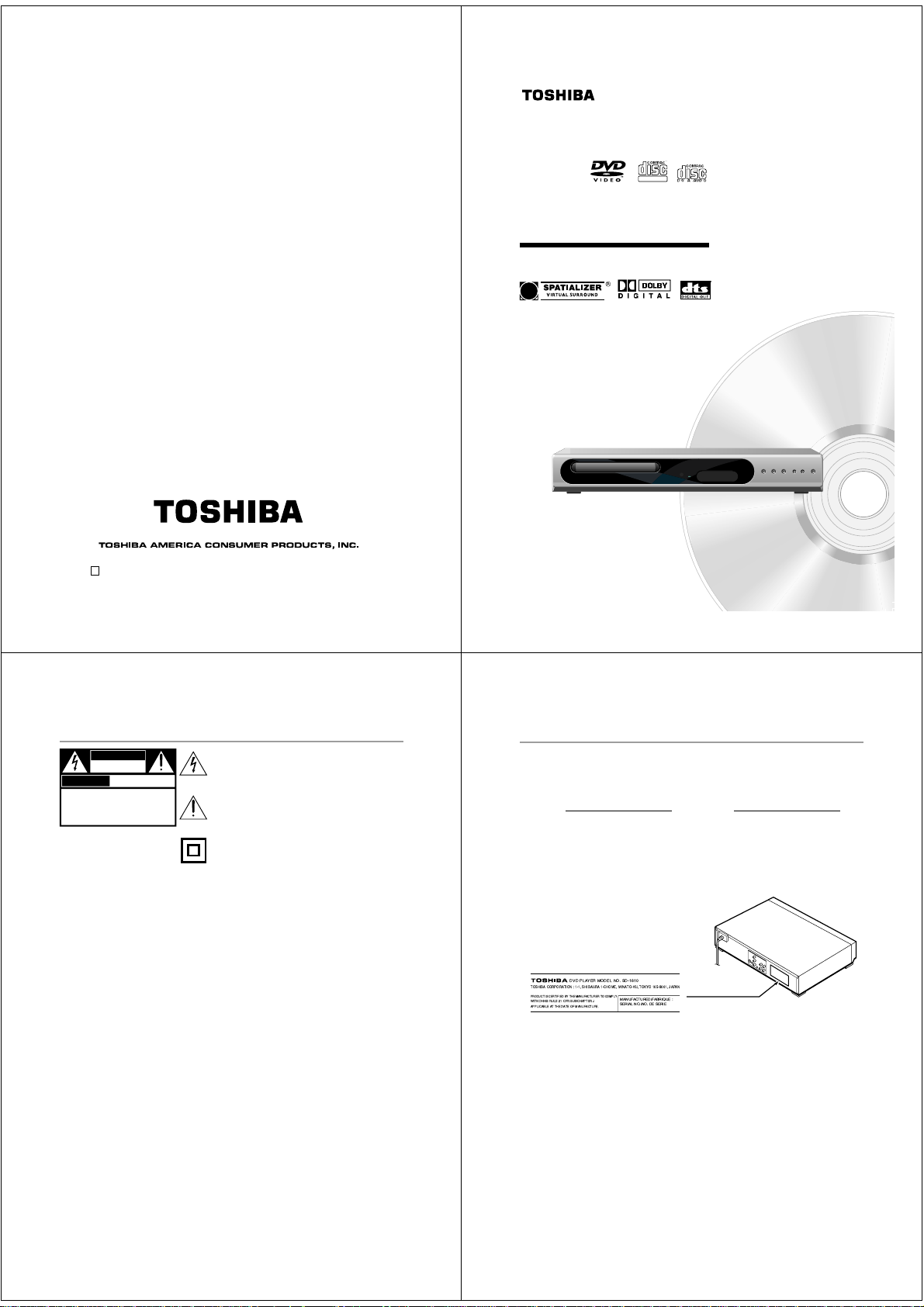
In the spaces provided below, record the Model and Serial No. located on the rear panel of your DVD video
player.
Model No. Serial No.
Retain this information for future reference.
Location of the required label
TOSHIBA CORPORATION : 1-1, SHIBAURA 1-CHOME, MINATO-KU, TOKYO 105-8001, JAPAN
PRODUCTIS CERTIFIED BYTHE MANUFACTURER TOCOMPLY
WITHDHHS RULE 21CFR SUBCHAPTER J
APPLICABLEAT THE DATEOF MANUFACTURE.
electric shock do not perform any servicing other than that contained in the operating
instructions unless you are qualified to do so.
DVD PLAYER MODEL NO. SD-1810
MANUFACTURED/FABRIQUE:
SERIALNO./NO. DE SERIE
2
3
Page 3
IMPORT ANT SAFEGUARDS
CAUTION: PLEASE READ AND OBSERVE ALL WARNINGS AND INSTRUCTIONS PROVIDED IN THIS
OWNER’S MANUAL AND THOSE MARKED ON THE UNIT . RETAIN THIS BOOKLET FOR
FUTURE REFERENCE.
This set has been designed and manufactured to assure personal safety. Improper use can result in electric
shock or fire hazard. The safeguards incorporated in this unit will protect you if you observe the following
procedures for installation, use and servicing. This unit is fully transistorized and does not contain any parts that
can be repaired by the user.
DO NOT REMOVE THE CABINET COVER, OR YOU MAY BE EXPOSED TO DANGEROUS VOLTAGE.
REFER SERVICING TO QUALIFIED SERVICE PERSONNEL ONL Y.
1. Read these instructions.
2. Keep these instructions.
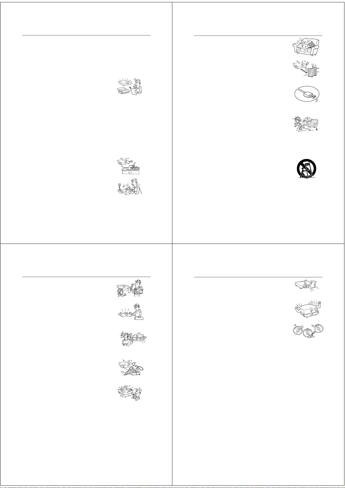
7. Do not block any ventilation openings. Install in accordance with the
manufacturer’s instructions.
8. Do not install near any heat sources such as radiators, heat registers, stoves,
or other apparatus (including amplifiers) that produce heat.
9. Do not defeat the safety purpose of the polarized or grounding-type plug. A
polarized plug has two blades with one wider than the other. A grounding
type plug has two blades and a third grounding prong. The wide blade or the
third prong are provided for your safety. If the provided plug does not fit into
your outlet, consult an electrician for replacement of the obsolete outlet.
3. Heed all warnings.
4. Follow all instructions.
5. Do not use this apparatus near water.
6. Clean only with dry cloth.
4
IMPORT ANT SAFEGUARDS (Continued)
13.Unplug this apparatus during lightning storms or when unused for long periods
of time.
10.Protect the power cord from being walked on or pinched particularly at plugs,
convenience receptacles, and the point where they exit from the apparatus.
11.Only use attachments/accessories specified by the manufacturer.
12.Use only with the cart, stand, tripod, bracket, or table specified by the
manufacturer, or sold with the apparatus. When a cart is used, use caution
when moving the cart/apparatus combination to avoid injury from tip-over.
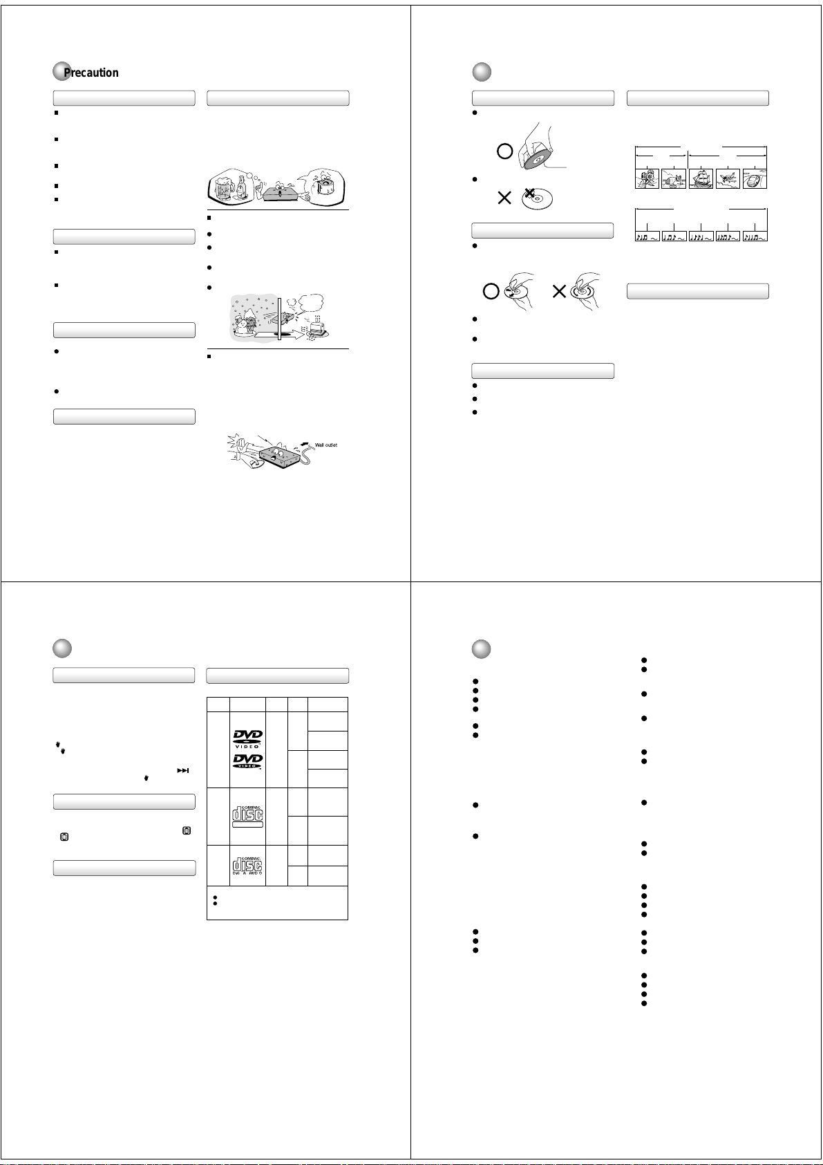
18.Keep your fingers well clear of the disc tray as it is closing. Neglecting to do
so may cause serious personal injury.
S3125A
5
14.Refer all servicing to qualified service personnel. Servicing is required when
the apparatus has been damaged in any way, such as power-supply cord or
plug is damaged, liquid has been spilled or objects have fallen into the
apparatus, the apparatus has been exposed to rain or moisture, does not
operate normally, or has been dropped.
15.When you use headphones on the amplifier, keep the volume at a moderate
level. If you use the headphones continuously with high volume sound, it
may cause hearing damage.
16.Do not overload wall outlets; extension cords, or integral convenience
receptacles as this can result in a risk of fire or electric shock.
17.Never insert objects of any kind into this apparatus through openings as
they may touch dangerous voltage points or short-out parts that could result
in a fire or electric shock. Never spill liquid of any kind on the apparatus.
6
19.Do not place a heavy object on or step on the apparatus. The object may fall,
causing serious personal injury and serious damage to the apparatus.
20.Do not use a cracked, deformed, or repaired disc. These discs are easily
broken and may cause serious personal injury and apparatus malfunction.
7
Page 4
Precautions
Notes on Discs
Notes on handling
When shipping the DVD video player, the original
shipping carton and packing materials come in handy.
For maximum protection, repack the unit as it was
originally packed at the factory.
Do not use volatile liquids, such as insect spray, near
the DVD video player. Do not leave rubber or plastic
products in contact with the DVD video player for a
long time. They will leave marks on the finish.
The top and rear panels of the DVD video player may
become warm after a long period of use. This is not a
malfunction.
When the DVD video player is not in use, be sure to
remove the disc and turn off the power.
If you do not use the DVD video player for a long
period, the unit may not function properly in the
future. Turn on and use the DVD video player
occasionally.
Notes on locating
Place the DVD video player on a level surface. Do not
use it on a shaky or unstable surface such as a
wobbling table or inclined stand. The loaded disc may
come off the proper position and cause damage to
the DVD video player.
When you place this DVD video player near a TV,
radio, or VCR, the playback picture may become poor
and the sound may be distorted. In this case, place
the DVD video player away from the TV, radio, or
VCR.
Notes on cleaning
Use a soft, dry cloth for cleaning.
For stubborn dirt, soak the cloth in a weak detergent
solution, wring well and wipe. Use a dry cloth to wipe
it dry.
Do not use any type of solvent, such as thinner and
benzine, as they may damage the surface of the DVD
video player.
If you use a chemical saturated cloth to clean the unit,
follow that product’s instructions.
To obtain a clear picture
The DVD video player is a high technology, precision
device. If the optical pick-up lens and disc drive parts
are dirty or worn down, the picture quality becomes
poor. To obtain a clear picture, we recommend regular
inspection and maintenance (cleaning or parts
replacement) every 1,000 hours of use depending on
the operating environment. For details, contact your
nearest dealer.
Notes on moisture condensation
Moisture condensation damages the DVD video
player. Please read the following carefully.
Moisture condensation occurs, for example, when you
pour a cold drink into a glass on a warm day. Drops of
water form on the outside of the glass. In the same way,
moisture may condense on the optical pick-up lens
inside this unit, one of the most crucial internal parts of
the DVD video player.
Moisture condensation occurs during the
following cases.
When you bring the DVD video player directly from a
cold place to a warm place.
When you use the DVD video player in a room where
you just turned on the heater, or a place where the
cold wind from the air conditioner directly hits the unit.
In summer, when you use the DVD video player in a
hot and humid place just after you move the unit from
an air conditioned room.
When you use the DVD video player in a humid place.
Do not use the DVD video player when moisture
condensation may occur.
If you use the DVD video player in such a situation, it
may damage discs and internal parts. Remove the
disc, connect the power cord of the DVD video player
to the wall outlet, turn on the DVD video player, and
leave it for two or three hours. After two or three
hours, the DVD video player will have warmed up and
evaporated any moisture. Keep the DVD video player
connected to the wall outlet and moisture
condensation will seldom occur.
Wait!
f
o
m
e
o
l
p
i
s
t
m
u
a
r
x
e
E
s
n
a
e
t
i
d
o
n
n
o
!
c
Optical pick-up
lens
o
to
It’s
!
rm
a
w
Wall outlet
On handling discs
Do not touch the playback side of the disc.
Do not attach paper or tape to discs.
Playback side
On cleaning discs
Fingerprints and dust on the disc cause picture and
sound deterioration. Wipe the disc from the center
outwards with a soft cloth. Always keep the disc
clean.
If you cannot wipe off the dust with a soft cloth, wipe
the disc lightly with a slightly moistened soft cloth and
finish with a dry cloth.
Do not use any type of solvent such as thinner,
benzine, commercially available cleaners or antistatic
spray for vinyl LPs. It may damage the disc.
On storing discs
Do not store discs in a place subject to direct sunlight
or near heat sources.
Do not store discs in places subject to moisture and
dust such as a bathroom or near a humidifier.
Store discs vertically in a case. Stacking or placing
objects on discs outside of their case may cause
warping.
Structure of disc contents
Normally, DVD video discs are divided into titles, and
the titles are sub-divided into chapters. VIDEO CDs and
audio CDs are divided into tracks.
DVD video disc
Chapter 1 Chapter 2 Chapter 1 Chapter 2 Chapter 3
VIDEO CD/audio CD
Track 1 Track 2 T rack 3 Track 4 Track 5
Each title, chapter or track is assigned a number, which
is called “title number”, “chapter number” or “track
number” respectively.
There may be discs that do not have these numbers.
DVD video disc
Title 1 Title 2
VIDEO CD/audio CD
Notes on copyright
It is forbidden by law to copy, broadcast, show,
broadcast on cable, play in public, and rent copyrighted
material without permission.
DVD video discs are copy protected, and any recordings
made from these discs will be distorted.
This product incorporates copyright protection
technology that is protected by method claims of certain
U.S. patents and other intellectual property rights owned
by Macrovision Corporation and other rights owners.
Use of this copyright protection technology must be
authorized by Macrovision Corporation, and is intended
for home and other limited viewing uses only unless
otherwise authorized by Macrovision Corporation.
Reverse engineering or disassembly is prohibited.
8
Notes on Discs (continued)
About this owner’s manual
This owner’s manual explains the basic instructions of
this DVD video player. Some DVD video discs are
produced in a manner that allows specific or limited
operation during playback. As such, the DVD video
player may not respond to all operating commands. This
is not a defect in the DVD video player. Refer to
instruction notes of discs.
” may appear on the TV screen during operation.
“
” means that the operation is not permitted by the
A “
DVD video player or the disc at the moment.
For example, sometimes it is unable to skip the playback
of copyright message of the disc when the SKIP(
button is pressed. Alternatively, the “
indicate that the feature is not available for the disc.
” may also
Notes on region numbers
The region number of this DVD video player is 1. If
region numbers, which stand for their playable area, are
printed on your DVD video disc and you do not find
ALL
or
, disc playback will not be allowed by the player.
(In this case, the DVD video player will display a
message on-screen.)
On VIDEO CDs
This DVD video player supports VIDEO CDs equipped
with the PBC (Version 2.0) function. (PBC is the
abbreviation of Playback Control.) You can enjoy two
playback variations depending on types of discs.
• VIDEO CD not equipped with PBC function
(Version 1.1)
Sound and movie can be played on this DVD video
player in the same way as an audio CD.
• VIDEO CD equipped with PBC function
(Version 2.0)
In addition to operation of a VIDEO CD not equipped
with the PBC function, you can enjoy playback of
interactive software with search function by using the
menu displayed on the TV screen (Menu Playback).
Some of the functions described in this owner’s
manual may not work with some discs.
Playable discs
This DVD video player can play the following discs.
Contents
Disc Mark
Audio
DVD
video
discs
)
VIDEO
CDs
1
DIGITAL VIDEO
Audio
CDs
The following discs are also available.
CD-R
CD-RW
CD-R/RW discs recorded by CD-DA method can be
played. Some CD-R/RW discs may be incompatible.
• You cannot play discs other than those listed above.
• You cannot play discs of DVD-RAM, DVD-RW, etc., or
non standardized discs even if they may be labeled as
above.
• This DVD video player uses the NTSC color system,
and cannot play DVD video discs recorded in any
other color system (PAL, SECAM, etc.).
• For MP3 CD, please see page 23.
video
(moving
pictures)
Audio
+
video
(moving
pictures)
Audio
+
12 cm
single)
Disc
Size
12 cm
8 cm
8 cm
12 cm
8 cm
(CD
Maximum
playback time
Approx. 4 hours
(single sided disc)
Approx. 8 hours
(double sided disc)
Approx. 80 minutes
(single sided disc)
Approx. 160 minutes
(double sided disc)
Approx. 74 minutes
Approx. 20 minutes
Approx. 74 minutes
Approx. 20 minutes
Table of Contents
Introduction
SAFETY PRECAUTIONS .......................... 2
IMPORTANT SAFEGUARDS.....................4
Precautions ...............................................8
Notes on Discs.......................................... 9
Notes on region numbers ............................... 10
Table of Contents....................................11
Identification of Controls .......................12
Front panel ..................................................... 12
Rear panel......................................................12
DVD display .................................................... 13
Remote control ............................................... 14
Loading batteries............................................ 15
Operating with the remote control .................. 15
Connections
Connecting to a TV ................................. 16
Connecting to a TV.........................................16
Connecting to an audio system and TV
equipped with component video inputs ........ 17
Connecting to Optional Equipment ...... 18
Connecting to an amplifier equipped with a
Dolby Digital decoder ................................... 18
Connecting to an amplifier equipped with
Dolby Pro Logic Surround ............................ 18
Connecting to an amplifier equipped with a
DTS decoder ................................................ 18
Connecting to an amplifier equipped with an
MPEG2 audio decoder.................................19
Connecting to an amplifier equipped with a
digital audio input ......................................... 19
Playback operation
Language setup ......................................20
Playback procedure................................ 21
Special playback.....................................22
Advanced Function
MP3 playback..............................................
Zooming/Locating desired scene .............
Zooming ......................................................... 24
Locating desired scene .................................. 24
Repeat playback ..................................... 25
Title, Chapter, Track and Folder Playback......25
A-B Repeat Playback ..................................... 25
Program playback/Random
playback (CD/VCD/MP3)......................... 26
Program playback .......................................... 26
Random playback........................................... 26
Marking desired scenes.........................27
Changing soundtrack language/Setting
the Spatializer/Subtitles .........................28
Changing soundtrack language......................28
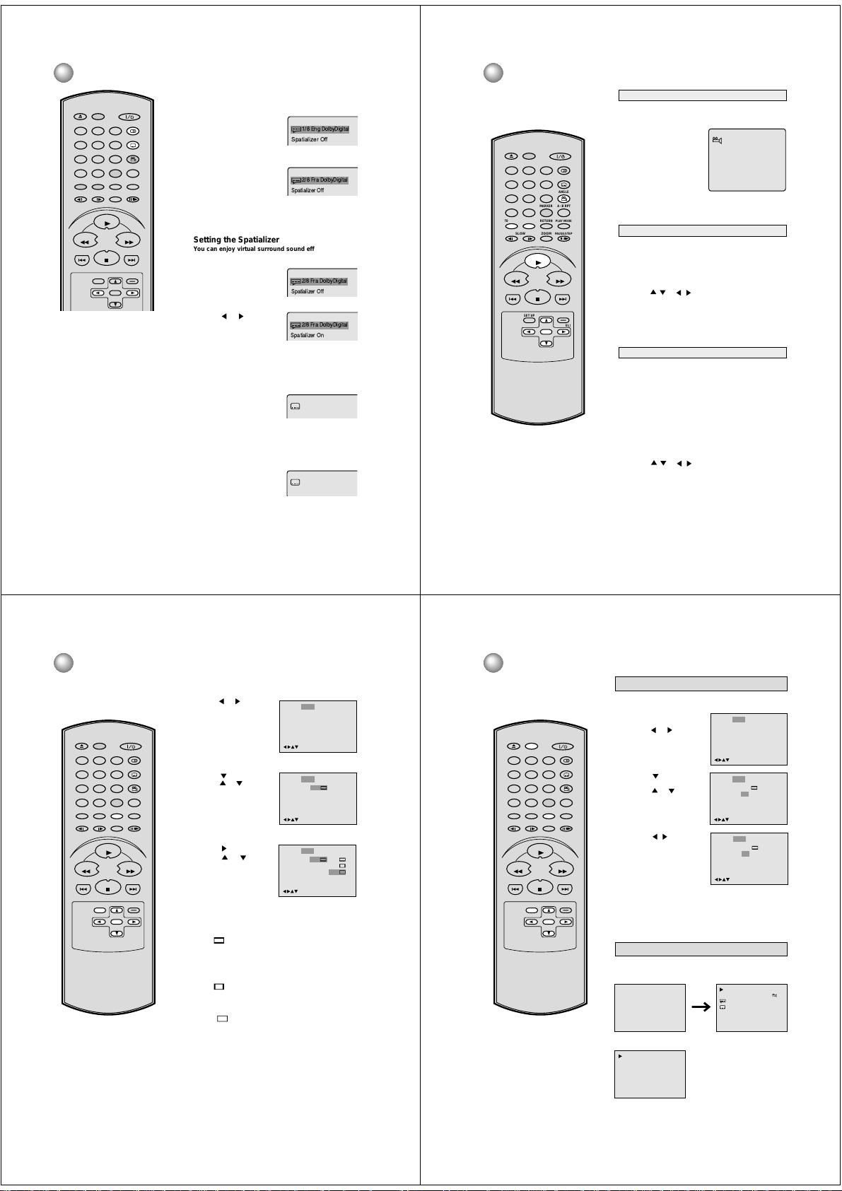
Setting the Spatializer .................................... 28
Subtitles.......................................................... 28
Changing angles/Title selection/DVD
menu ........................................................29
Changing angles ............................................ 29
Title selection ................................................. 29
DVD menu ...................................................... 29
Setting the aspect ratio of TV screen.... 30
Setting on Screen display/
Disc status ..............................................31
Setting on Screen display...............................31
Disc status......................................................31
Dynamic Range Control.........................32
Parental control setting.......................... 33
To change the parental level..................34
Temporary disabling of rating level of
DVD disc ..................................................35
Setting menu language ..........................36
Setting subtitle language.......................37
Setting audio soundtrack language......38
Others
Language code list .................................39
Before Calling Service Personnel ......... 40
Specifications ......................................... 41
LIMITED WARRANTY DVD VIDEO
PLAYER ...................................................42
9
23
24
10
11
Page 5
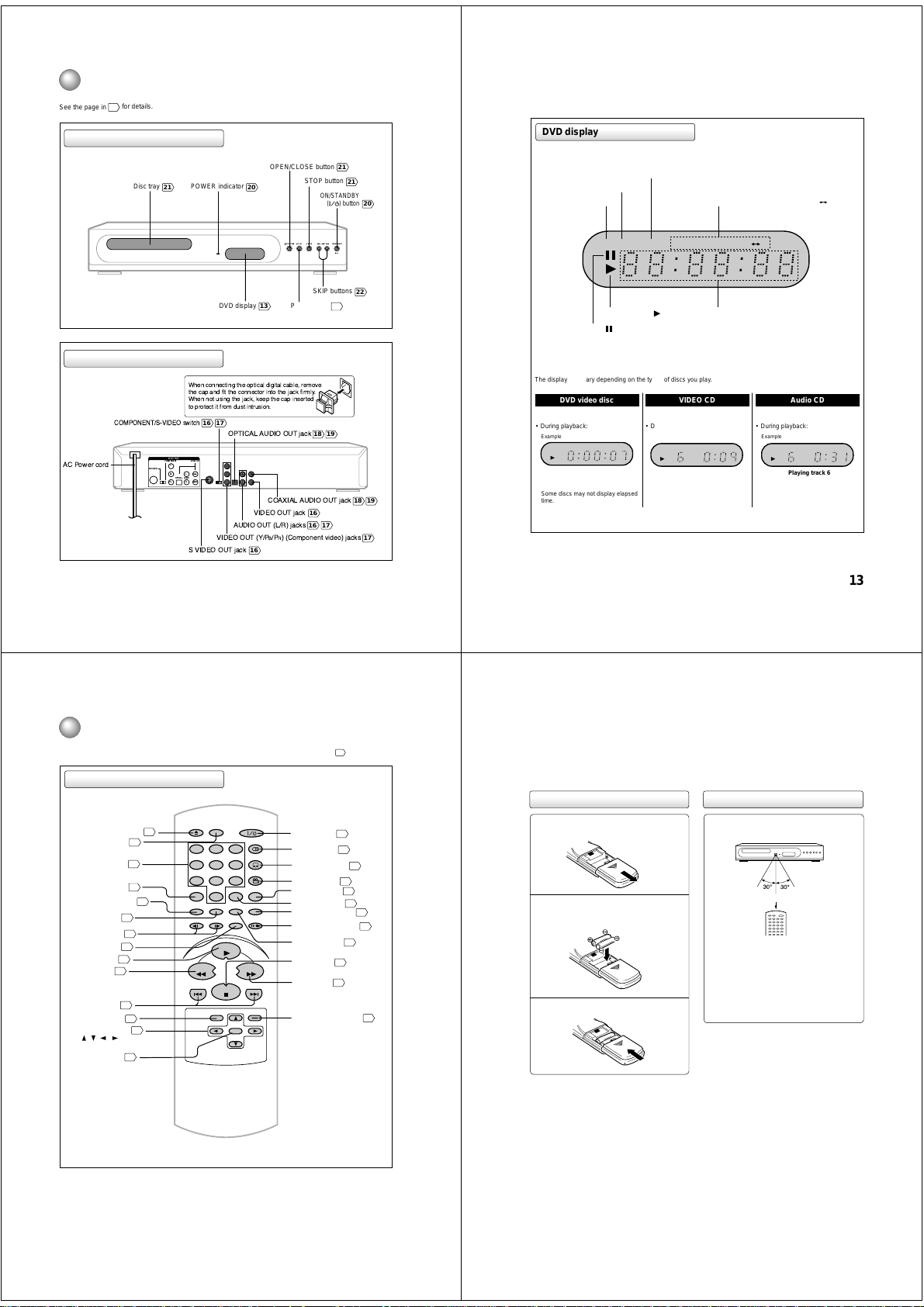
Identification of Controls
See the page in
Front panel
for details.
DVD display
Rear panel
AC Power cord
12
Disc tray
21
COMPONENT/S-VIDEO switch
OUTPUT
COMPONENT
Y
S-VIDEO
L
P
B
OPTICAL AUDIO
P
R
R
OPEN/CLOSE button
POWER indicator
20
DVD display
When connecting the optical digital cable, remove
the cap and fit the connector into the jack firmly.
When not using the jack, keep the cap inserted
to protect it from dust intrusion.
16 17
OPTICAL AUDIO OUT jack
DIGITAL
COAXIAL
VEDIO
VIDEO OUT jack
AUDIO OUT (L/R) jacks
VIDEO OUT (Y/PB/PR) (Component video) jacks
S VIDEO OUT jack
16
STOP button
PLAY button
13
COAXIAL AUDIO OUT jack
16
16 17
21
ON/STANDBY
( ) button
SKIP buttons
21
18 19
21
22
18 19
CD indicator (CD)
20
DVD indicator (DVD)
DVD CD
TRACK
Play indicator ( )
Pause indicator ( )
The display may vary depending on the types of discs you play.
DVD video disc Audio CD
• During playback:
Example
DVD
Some discs may not display elapsed
time.
17
• During playback:
Repeat mode indicators
(ALL REPEAT, REPEAT, REPEAT A B)
ALL
REPEAT
AB
Message or number indicator
(Title, chapter, track, playing time or other information)
VIDEO CD
• During playback:
Example
TRACK
Playing track 6
Some discs may not display track
numbers or elapsed time.
Example
CD TRACK
Playing track 6
Some discs may not display track
numbers or elapsed time.
13
TRACK indicator (TRACK)
Identification of Controls (continued)
The instructions in this manual describe the functions on the remote control. See the page in
Remote control
DISPLAY
OPEN/CLOSE
OPEN/CLOSE button
DISPLAY button
Number buttons
SEARCH button
TOP MENU button
MENU button
SLOW buttons
ZOOM button
PLAY button
REV button
SKIP buttons
SET UP button
Direction buttons
( / / / )
ENTER button
21
31
24
24
29
29
22
24
21
22
22
20
20
20
321
654
79
8
SEARCH
(JUMP)
0T
PLAY MODE
RETURN
TOP MENU
MENU
PAUSE/STEP
ZOOMSLOW
PLAY
REV FWD
SKIP
STOP
SET UP
ENTER
AUDIO
SUBTITLE
ANGLE
A - B RPTMARKER
SKIP
CLEAR
(CANCEL)
Power button
AUDIO button
SUBTITLE button
ANGLE button
A-B RPT button
MARKER button
PLAY MODE button
PAUSE/STEP button
RETURN button
STOP button
FWD button
CLEAR (CANCEL) button
20
28
29
21
22
for details.
28
25
27
25
22
20
24
14
Loading batteries
Slide the battery compartment cover in the
direction of the arrow.
1
Install two "AAA" batteries (supplied), paying
2
attention to the polarity diagram in the battery
compartment.
Replace the compartment cover.
3
Notes on batteries
Improper use of batteries may cause battery leakage and
corrosion. To operate the remote control correctly, follow the
instructions below.
• Do not insert batteries into the remote control in the wrong
direction.
• Do not charge, heat, open, or short-circuit the batteries.
Do not throw batteries into a fire.
• Do not leave dead or exhausted batteries in the remote
control.
• Do not use different types of batteries together, or mix old
and new batteries.
• If you do not use the remote control for a long period of
time, remove the batteries to avoid possible damage from
battery corrosion.
• If the remote control does not function correctly or if the
operating range becomes reduced, replace all batteries
with new ones.
• If battery leakage occurs, wipe the battery liquid from the
battery compartment, then insert new batteries.
Operating with the remote control
Point the remote control at the remote
sensor and press the buttons.
Within about 7 m (23 feet)
Distance: About 7 m (23 feet) from the front of the
remote sensor
Angle: About 30° in each direction of the front of
the remote sensor
* Do not expose the remote sensor of the DVD video
player to a strong light source such as direct
sunlight or other illumination. If you do so, you may
not be able to operate the DVD video player via the
remote control.
Notes on the remote control
• Direct the remote control at the remote sensor of the DVD
video player.
• Do not drop or give the remote control a shock.
• Do not leave the remote control near an extremely hot or
humid place.
• Do not spill water or put anything wet on the remote
control.
• Do not disassemble the remote control.
• When using the remote control, press the button at
intervals of about 1 second to ensure the correct mode of
operation.
15
Page 6
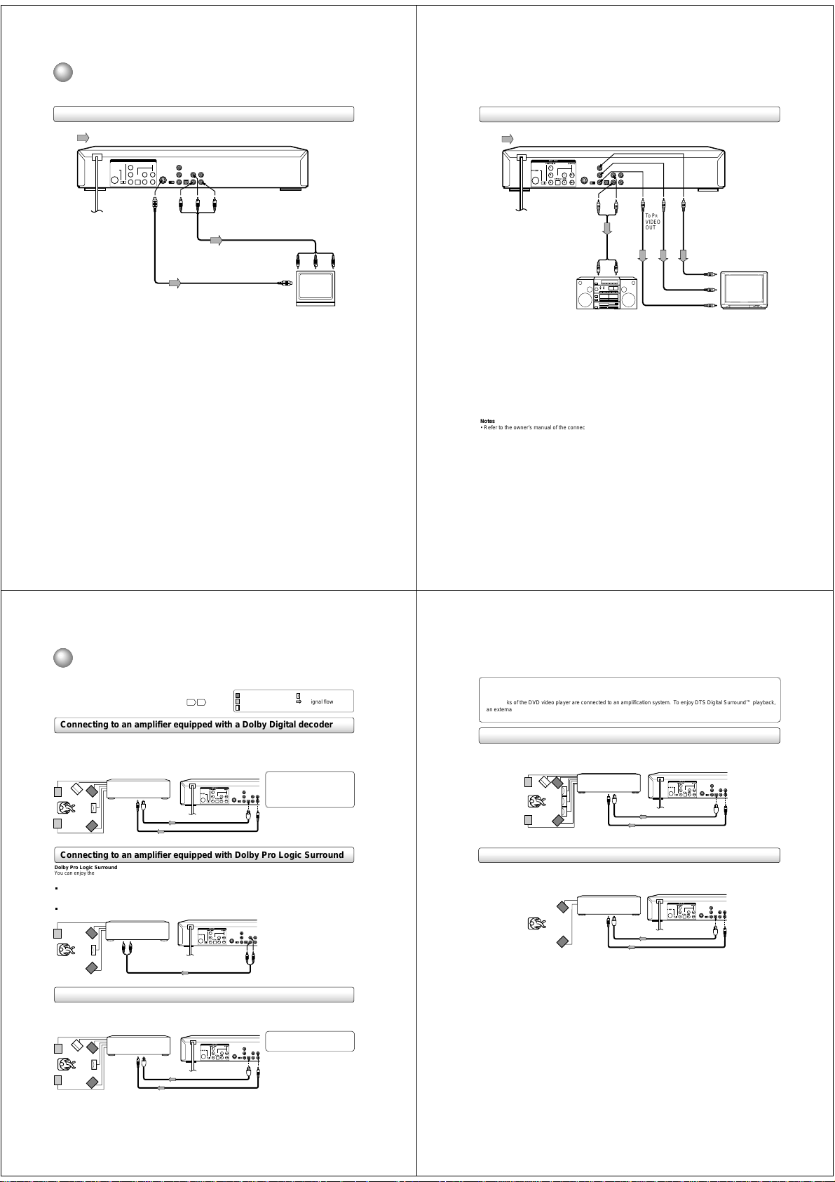
Connecting to a TV
Connect the DVD video player to your TV.
Connecting to a TV
Signal flow
OUT PUT
DIGITAL
COMPONENT
Y
S-VIDEO
COAXIAL
L
B
P
OPTICAL AUDIO
VEDIO
P
R
R
To wall outlet
To S
(red)
(white)
VIDEO
OUT
To VIDEO
OUT
(yellow)
To AUDIO OUT
Audio/video cable (supplied)
S video cable (not supplied)
If the TV has an S video input, connect the
DVD video player with an S video cable.
When using an S video cable, do not
connect the yellow video cable.
Set the COMPONENT/S-VIDEO switch to
the S-VIDEO position.
To video input
To S video input
(red)
TV or monitor with
audio/video inputs
To audio inputs
(white)
(yellow)
Connecting to an audio system and TV equipped with component video inputs
Signal flow
OUTPUT
DIGITAL
COMPONENT
Y
S-VIDEO
COAXIAL
L
B
P
OPTICAL AUDIO
VEDIO
P
R
R
(red)
(white)
To P R
To Y
To AUDIO OUT
To audio inputs of
the amplifier
(red) (white)
Audio system
Component video (ColorStream®) outputs/inputs
Some TVs or monitors are equipped with component video inputs. Connecting to these inputs allows you to enjoy
higher quality picture playback.
Set the COMPONENT/S-VIDEO switch to the COMPONENT position.
Actual labels for component video inputs may vary depending on the TV manufacturer. (ex. Y, R-Y, B-Y or Y, C
In some TVs or monitors, the color levels of the playback picture may be reduced slightly or the tint may change. In
such a case, adjust the TV or monitor for optimum performance.
VIDEO
OUT
To P B
VIDEO
OUT
To P
To P
VIDEO
OUT
To Y video
B video input
R video input
input
TV or monitor with
component video inputs
B, CR)
Notes
• Refer to the owner’s manual of the connected TV as well.
• When you connect the DVD video player to your TV, be sure to turn off the power and unplug both units from the wall outlet
before making any connections.
• If your television set has one audio input, connect the left and right audio outputs of the DVD video player to a Y cable
adapter (not supplied) and then connect to your TV.
• Connect the DVD video player directly to your TV. If you connect the DVD video player to a VCR, TV/VCR combination or
video selector, the playback picture may be distorted as DVD video discs are copy protected.
16
Connecting to Optional Equipment
You can enjoy high quality dynamic sounds by connecting the DVD video
player to optional audio equipment.
16
For connection to your TV, see “Connecting to a TV”
17
Connecting to an amplifier equipped with a Dolby Digital decoder
Dolby Digital
Dolby Digital is the surround sound technology used in theaters showing the latest movies, and is now available to reproduce this
realistic effect in the home. You can enjoy motion picture and live concert DVD video discs with this dynamic realistic sound by
connecting the DVD video player to a 6 channel amplifier equipped with a Dolby Digital decoder or Dolby Digital processor. If you have
a Dolby Pro Logic Surround decoder, you will obtain the full benefit of Pro Logic from the same DVD movies that provide full 5.1channel Dolby Digital soundtracks, as well as from titles with the Dolby Surround mark.
Amplifier equipped with a
Dolby Digital decoder
To COAXIAL
To OPTICAL
type digital
type digital
audio input
audio input
Optical digital cable
75 Ω coaxial cable
: Front speaker
: Rear speaker
.
: Sub woofer
OUTPUT
COMPONENT
DIGITAL
Y
S-VIDEO
COAXIAL
L
P
B
OPTICALAUDIO
VEDIO
P
R
R
: Center speaker
: Signal flow
Manufactured under license from Dolby
Laboratories. “Dolby” “Pro Logic” and
the double-D symbol are trademarks of
Dolby Laboratories. Confidential
unpublished works. ©1992-1997 Dolby
Laboratories. All rights reserved.
Connect either.
Notes
• Refer to the owner’s manual of the connected equipment as well.
• When you connect the DVD video player to other equipment, be sure to turn off the power and unplug all of the equipment
from the wall outlet before making any connections.
• If you place the DVD video player near a tuner or radio, the radio broadcast sound might be distorted. In this case, place the
DVD video player away from the tuner and radio.
• The output sound of the DVD video player has a wide dynamic range. Be sure to adjust the receiver’s volume to a moderate
listening level. Otherwise, the speakers may be damaged by a sudden high volume sound.
• Turn off the amplifier before you connect or disconnect the DVD video player’s power cord. If you leave the amplifier power
on, the speakers may be damaged.
Warning
• When playing DTS-encoded discs (DVD video discs and audio CDs), excessive noise may be output from the analog
stereo jacks. To avoid possible damage to the audio system, you should take proper precautions when the AUDIO OUT
(L/R) jacks of the DVD video player are connected to an amplification system. To enjoy DTS Digital Surround™ playback,
an external 5.1 channel DTS Digital Surround™ decoder system must be connected to the OPTICAL AUDIO OUT jack or
COAXIAL AUDIO OUT jack of the DVD video player .
Connecting to an amplifier equipped with an MPEG2 audio decoder
MPEG2 sound
You can enjoy motion picture and live concert DVD video discs with dynamic realistic sound by connecting an amplifier equipped with
an MPEG2 audio decoder or MPEG2 audio processor.
Amplifier equipped with an
MPEG2 audio decoder
To OPTICAL
To COAXIAL
type digital
type digital
audio input
audio input
OUTPUT
COMPONENT
Y
S-VIDEO
P
P
Optical digital cable
75 Ω coaxial cable
DIGITAL
COAXIAL
L
B
OPTICALAUDIO
VEDIO
R
R
Connect either.
17
Connecting to an amplifier equipped with Dolby Pro Logic Surround
Dolby Pro Logic Surround
You can enjoy the dynamic realistic sound of Dolby Pro Logic Surround by connecting an amplifier and speaker system (right and left
front speakers, a center speaker, and one or two rear speakers).
With an amplifier equipped with Dolby Digital Connect the equipment the same way as described in “Connecting to an amplifier
equipped with a Dolby Digital decoder.” Refer to that amplifier’s owner’s manual and set the amplifier so you can enjoy Dolby Pro
Logic Surround sound.
With an amplifier not equipped with Dolby Digital Connect the equipment as follows.
Amplifier equipped with
*
Dolby Pro Logic Surround
To audio input
Audio cable
COMPONENT
S-VIDEO
OUTPUT
DIGITAL
Y
COAXIAL
L
B
P
OPTICALAUDIO
VEDIO
P
R
R
To AUDIO OUT
* Connect one or two rear speakers.
The output sound from the rear speakers
will be monaural even if you connect two
rear speakers.
Connecting to an amplifier equipped with a DTS decoder
Digital Theater Systems (DTS)
DTS is a high quality surround technology used in theaters and now available for home use, on DVD video discs or audio CDs.
If you have a DTS decoder or processor, you can obtain the full benefit of 5.1 channel DTS encoded sound tracks on DVD video discs
or audio CDs.
Amplifier equipped with
a DTS decoder
To COAXIAL
type digital
audio input
To OPTICAL
type digital
audio input
COMPONENT
S-VIDEO
Optical digital cable
75 Ω coaxial cable
OUTPUT
DIGITAL
Y
COAXIAL
L
B
P
OPTICALAUDIO
VEDIO
P
R
R
“DTS” and “DTS Digital Surround” are
trademarks of Digital Theater Systems,
Inc.
Connect either.
18
Connecting to an amplifier equipped with a digital audio input
2 channel digital stereo
You can enjoy the dynamic sound of 2 channel digital stereo by connecting an amplifier equipped with a digital audio input and speaker
system (right and left front speakers).
Amplifier equipped with
a digital audio input
To COAXIAL
type digital
audio input
Notes
• DO NOT connect the OPTICAL AUDIO OUT jack or COAXIAL AUDIO OUT jack of the DVD video player to the AC-3 RF
input of a Dolby Digital Receiver. This input on your A/V Receiver is reserved for Laserdisc use only and is incompatible with
the OPTICAL AUDIO OUT jack or COAXIAL AUDIO OUT jack of the DVD video player.
• Connect the OPTICAL AUDIO OUT jack or COAXIAL AUDIO OUT jack of the DVD video player to the “OPTICAL” or
“COAXIAL” input of a Receiver or Processor.
• Refer to the owner’s manual of the connected equipment as well.
• When you connect the DVD video player to other equipment, be sure to turn off the power and unplug all of the equipment
from the wall outlet before making any connections.
• The output sound of the DVD video player has a wide dynamic range. Be sure to adjust the receiver’s volume to a moderate
listening level. Otherwise, the speakers may be damaged by a sudden high volume sound.
• Turn off the amplifier before you connect or disconnect the DVD video player’s power cord. If you leave the amplifier power
on, the speakers may be damaged.
To OPTICAL
type digital
audio input
OUTPUT
COMPONENT
Y
S-VIDEO
P
B
OPTICALAUDIO
P
R
Optical digital cable
75 Ω coaxial cable
DIGITAL
COAXIAL
L
VEDIO
R
Connect either.
19
Page 7
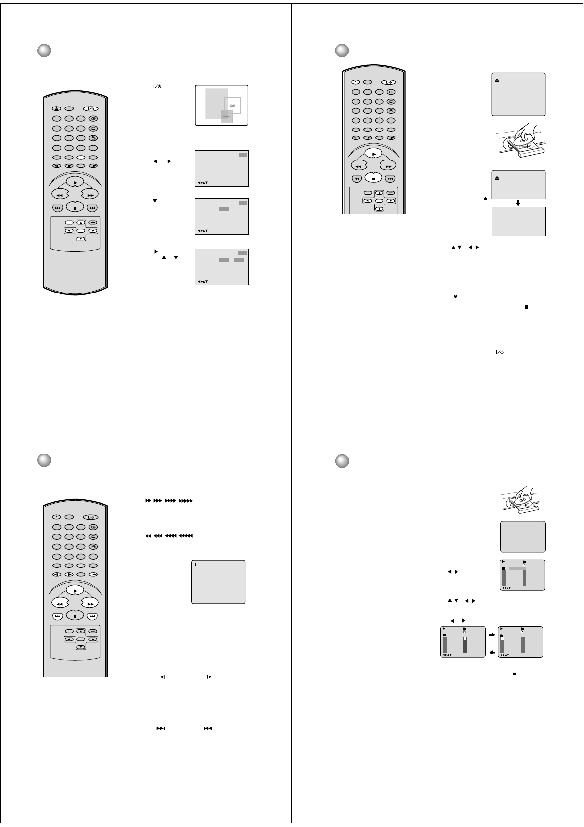
Language setup
The setup language can be selected.
DISPLAY
OPEN/CLOSE
79
SEARCH
(JUMP)
TOP MENU
REV FWD
SKIP
•
If the unit does not operate properly:
Static electricity, etc., may affect the player's operation. Disconnect the AC power
cord once, then connect it again.
MENU
SET UP
AUDIO
321
SUBTITLE
654
ANGLE
8
A - B RPTMARKER
0T
PLAY MODE
RETURN
PAUSE/STEP
ZOOMSLOW
PLAY
SKIP
STOP
CLEAR
(CANCEL)
ENTER
20
Preparation
• Turn ON the TV and select to the corresponding video input.
• When using an amplifier, switch on the amplifier.
Press (POWER) on
1
the unit or on the remote
control to turn on the unit.
The POWER indicator will
light up.
“Reading” display will
change to “No Disc”.
(If DVD disc has already
loaded, playback will start
automatically.)
From the stop mode press
2
SET UP.
Press
or to select
“Other”.
Press or ENTER
3
to select “OSD Language”.
or ENTER and
Press
4
or to se-
then press
lect desired language(e.g.
English), then press
ENTER.
NOTE: To exit the SETUP screen, press SET UP
(or RETURN) while the SETUP screen is displayed.
No Disc
welcome
Picture ParentalSound
Language Other
/Enter/Setup/Return
Language
Picture ParentalSound
OSD Language English
/Enter/Setup/Return
Language
Picture ParentalSound
OSD Language English English
/Enter/Setup/Return
Francais
Espanol
Other
Other
Playback procedure
DISPLAY
OPEN/CLOSE
79
SEARCH
(JUMP)
TOP MENU
REV FWD
SKIP
Note:
If a non-compatible disc is loaded, "Incorrect
•
Disc", "Region Code Error" or "Parental
Error" will appear on the TV screen according to the type of loaded disc. In this case,
check your disc again (See pages 10 and
33).
• Some discs may take a minute or so to start
playback.
• When you insert a disc with the label facing
downwards (ie. the wrong way up) and press
PLAY or CLOSE on the unit, "Reading" will
appear on the display for 10 seconds and
then "Incorrect Disc" will be displayed.
• Some playback functions of DVDs may be
intentionally fixed by software producers.
This unit plays DVDs in accordance with the
design intent of the software producers.
Some playback features may not be available. Also refer to the instructions supplied
with the DVD.
• When playing DTS-encoded Audio CDs,
excessive noise will be heard from the analogue stereo outputs. To avoid possible
damage to the audio system, take proper
precautions when the analogue stereo outputs of the DVD player are connected to an
amplification system.
MENU
SET UP
AUDIO
321
SUBTITLE
654
ANGLE
8
A - B RPTMARKER
0T
PLAY MODE
RETURN
PAUSE/STEP
ZOOMSLOW
PLAY
SKIP
STOP
CLEAR
(CANCEL)
ENTER
Press OPEN/CLOSE on
1
the unit or on the remote
control. The disc tray will
open.
Place a disc onto the tray.
2
Hold the disc, position it with
the printed label side up,
align it with the guides, and
place it in its proper position.
Press PLAY or OPEN/
3
CLOSE on the unit or on
the remote control.
The disc tray closes automatically.
The TV-screen display,
changes to “Reading” and
then playback
commences.
• A menu screen will
appear on the TV screen,
if the disc has a menu
feature.
Press / or / to select desired title.
4
Press ENTER.
5
• Title is selected and play commences.
Press STOP to end playback.
6
• The unit memorizes the stop location, depending on the
disc. “
” appears on the screen. Press PLAY to
resume playback (from the stopped location).
• If you press STOP again or unload the disc (“
on the screen.), the unit will clear the stopped location
from its memory.
To stop playback, press STOP.
7
Then press OPEN/CLOSE on the unit or on the remote
control.
The disc tray opens.
Remove the disc and press OPEN/CLOSE on the unit or on
the remote control then press
The disc tray closes automatically and unit turns off.
Reading
(POWER).
” appears
21
Special playback
Note: there may be a slight delay between you pressing the button and the
function activating.
DISPLAY
OPEN/CLOSE
79
SEARCH
(JUMP)
TOP MENU
REV FWD
SKIP
Note:
The unit is capable of displaying a still video
image or On Screen Display image on your
television indefinitely.
video image or On screen display image
displayed on your TV for an extended period of time, you risk permanent damage
to your television screen. Projection
televisions are particularly susceptible. If
you must display a still image for a
prolonged time, reduce the contrast and
brightness of your set.
This, however, will not insure damage will
not occur to your screen always exercise
caution when displaying still images.
321
654
8
0T
RETURN
MENU
ZOOMSLOW
PLAY
STOP
SET UP
ENTER
If you leave a still
AUDIO
SUBTITLE
ANGLE
A - B RPTMARKER
PLAY MODE
PAUSE/STEP
SKIP
CLEAR
(CANCEL)
22
Fast Forward Playback
Press FWD during normal playback.
Each press of the FWD button will increase the speed of the
, , , .
search
• To resume normal playback, press PLAY.
Review Playback
Press REV during normal playback.
Each press of the REV button will increase the speed of the
, , , .
search
• To resume normal playback, press PLAY.
Still Playback
Press PAUSE/STEP during
normal playback to pause
playback.
To resume normal playback,
press PLAY.
Frame Advance
Press PAUSE/STEP during still playback.
One frame is advanced each time you press PAUSE/STEP.
To resume normal playback, press PLAY.
Slow-motion Playback
Press SLOW( ) Reverse or SLOW
normal playback or still playback.
Each press of SLOW will change the speed of the slow x1/2,
x1/4, x1/6, x1/7.
• To resume normal playback, press PLAY.
• To resume the still playback, press PAUSE/STEP.
Locating a chapter or track
Press SKIP(
playback to locate a chapter that you want to watch.
Each time you press the button, a chapter or track is
skipped.
) Forward or SKIP( ) Reverse during
( )
Forward during
MP3 Playback
This player can play back the MP3-data
which has been recorded on CD-R or CDRW. To produce the MP3-data, you need a
Windows-PC with CD-ROM drive and a MP3encoding Software (not supplied).
The Apple-HFS-System can not be played.
MP3 CD Information
Limitations on MP3 CD playback
• MP3 CD is the disc that is standardized by
ISO9660, its file name must include 3-digits
extension letters, “mp3”.
• The directory and file names of the MP3
CD must correspond to the ISO
standardized files.
• This unit can read 200 files per disc. If
one directory has more than 200 files, it
reads up to 200 files, the remaining files will
be omitted.
• As for multi-session disc, only the first
session can be played.
• If the CD has both audio tracks and MP3
files, only audio tracks are played.
• It may take more than one minute for this
unit to read MP3 files depending on its
structure.
• Music recorded by “Joliet Recording
Specification” can be played back, the file
name is displayed (within 17 letters) on the
screen. Long file names will be condensed.
• The music files recorded by “Hierarchical
File System” (HFS) cannot be played.
Limitations on display
• The maximum number for display is 17
letters. Available letters for display are the
following: capital or small alphabets of A
through Z, numbers of 0 through 9, and _
(under score).
• Other characters than those above are
replaced in hyphen.
Notes on MP3 files
To play back a MP3 CD in the recorded order ,
1. Use MP3 software that records data
alphabetically or numerically.
2. Name each file including two-digit or three-
digit number (e.g. “01” “02” or “001” “002”).
3. Refrain from making too many sub-folders.
CAUTION:
• Some MP3 CDs cannot be played back
depending on the recording conditions.
• A CD-R/RW that has no music data or
non-MP3 files cannot be played back.
Preparation:
Turn ON the TV and select the corresponding video input.
•
Press OPEN/CLOSE.
1
The disc tray will open.
Place a disc onto the tray.
Press PLAY or OPEN/CLOSE.
2
The disc tray closes automatically.
Reading” will appear followed
“
on screen, by reading file number.
Reading time will vary depending
on the number of files.
A MP3 menu screen will appear
3
on the TV screen.
Press
/ or ENTER to select
desired folder.
Press
/ or / or Number keys to select the desired
4
track, then press ENTER. Track is selected and play
commences.
• In the event the folder includes more than 11 tracks,
or to display next track list.
press
Press STOP to end playback.
5
• The unit memorizes the stopped point. “
the screen. Press PLAY to resume playback (from the
memorized location point).
• If you press STOP again or unload the disc, the unit will
clear the memorized location from its memory.
Then press OPEN/CLOSE.
6
The disc tray opens.
Remove the disc and press POWER.
The disc tray closes automatically and DVD turns off.
NOTES:
• During MP3-Playback, you cannot use SEARCH, or A-B
Repeat functions.
• You can use Repeat(Track, All or Folder), Random and Program
functions for MP3 CD Playback.(See page 25 and 26)
• MP3-Playback may take two minutes or so to start the reading
for the first time.
Track 1/12
1
Pops
1
Japan
2
Bay Bridge
3
CLOSE MY EYES
4
DIVE TO BLUE
5
Honey
01:28 Japan
6
7
8
9
10
/0-9/Enter/Play Mode
Jazz
BLUE EYES
Blurry Eyes
flower
Lies and Truth
winter fall
Reading
MP3 15
Track 1/12
01:28 Japan
1
Pops
1
Japan
6
2
7
Bay Bridge
3
8
CLOSE MY EYES
4
9
DIVE TO BLUE
5
10
Honey
/0-9/Enter/Play Mode
Track 1/12 01:28 Japan
1
Pops
11
Mother
12
Hold Your Last
/0-9/Enter/Play Mode
” appears on
Jazz
BLUE EYES
Blurry Eyes
flower
Lies and Truthwinter fall
Jazz
23
Page 8
Zooming/Locating desired scene
Marker 2
Marker 1
Marker 3
/Enter/Clear/Marker
Marker 2
Marker 1
Marker 3
/Enter/Clear/Marker
2700 54
Marker 2
Marker 1
Marker 3
/Enter/Clear/Marker
27
16
08
54
25
31
00
01
02
Marker 2
Marker 1
Marker 3
/Enter/Clear/Marker
27
16
08
54
25
31
00
01
02
Zooming
This unit will allow you to zoom in on an image. You can
then make selections by switching the position of the
zoom point on the frame.
Press ZOOM during play-
1
DISPLAY
OPEN/CLOSE
321
654
79
8
SEARCH
(JUMP)
0T
RETURN
TOP MENU
MENU
ZOOMSLOW
PLAY
REV FWD
SKIP
STOP
SET UP
ENTER
AUDIO
SUBTITLE
ANGLE
A - B RPTMARKER
PLAY MODE
PAUSE/STEP
SKIP
CLEAR
(CANCEL)
back.
The center part of the
image will be zoomed.
Each press of ZOOM will
change the ZOOM power.
1 (x 1.3),
3 (x 2.0).
and
Press
/
2
You may move the frame from the center position to UP,
DOWN, LEFT or RIGHT direction.
In the zoom mode press ZOOM repeatedly to return to a
3
Locating Desired Scene
Use the title, chapter and time recorded on the disc to
locate the desired to play back point.
1
1:1 view (
SEARCH (JUMP
Press
during playback.
Off).
1
2 (x 1.5)
/ / to view a different part of the frame.
)
Jump Time
Title
Chapter
/Enter/0 9/Clear/Jump
Repeat playback
DISPLAY
OPEN/CLOSE
79
SEARCH
(JUMP)
TOP MENU
REV FWD
SKIP
MENU
SET UP
AUDIO
321
SUBTITLE
654
ANGLE
8
A - B RPTMARKER
0T
PLAY MODE
RETURN
PAUSE/STEP
ZOOMSLOW
PLAY
SKIP
STOP
CLEAR
(CANCEL)
ENTER
Title, Chapter, Track and Folder Playback
Press PLAY MODE during playback or stop mode.
DVD
Press / or ENTER once or twice to select “Chapter” or
“Title”.
:
Repeat
Off
to select “Repeat”.
:
:
/Enter/Play Mode
Repeat
/Enter/Play Mode
/ or ENTER once or twice to select
Play Mode Off
Repeat::
/Enter/Play Mode
/Enter/Play Mode
Audio MP3/CD
Press
In case of CD, press
“Track” or “All”.
Play Mode Off
Repeat Off
You can also select “Folder” when
playing MP3 encoded CD’s.
Press PLAY MODE again to exit the On Screen Display.
In case of CD, press PLAY to start Repeat playback.
To resume normal playback, select Repeat “Off”.
A-B Repeat Playback
A-B repeat playback allows you to repeat material between
two selected points.
Press A-B RPT during
1
playback.
The start point is selected.
Repeat
Chapter
:
Track
A
:
/Enter/Play Mode
:
Play Mode Off
Repeat
:
/Enter/Play Mode
Play Mode Off
Repeat::
/Enter/Play Mode
Title
All
Folder
Press
to select the “Time”, “Title” or “Chapter”.
or
2
Note:
• You can select Pause, Slow or
Search playback from the zoom mode.
• Some discs may not respond to the
zoom feature.
24
Number buttons (0-9)
Press
3
• If you input a wrong number, press
• Refer to the package supplied with the disc to check the
numbers.
ENTER
Press
4
• Playback starts.
• When you change the title, playback starts from
Chapter 1 of the selected title.
• Some discs may not be compatible with the above
operation.
to change the number.
CLEAR (CANCEL
.
Program playback/Random playback (CD/ VCD/MP3)
You can arrange the playback order of
tracks on the disc.
DISPLAY
OPEN/CLOSE
79
SEARCH
(JUMP)
TOP MENU
REV FWD
SKIP
SET UP
AUDIO
321
SUBTITLE
654
ANGLE
8
A - B RPTMARKER
0T
PLAY MODE
RETURN
MENU
PAUSE/STEP
ZOOMSLOW
PLAY
SKIP
STOP
CLEAR
(CANCEL)
ENTER
Program playback
Press PLAY MODE in the stop mode.
1
Press / to select Play
2
Mode, then press
select program.
Press / or / to
3
select the programming position. Use Numbered but-
tons (0-9) to input the Track
numbers.
• To program others, repeat
Step 3.
• If you input a wrong
press CLEAR
number,
(CANCEL).
Press / or / to
4
select “Program Playback”
and press ENTER.
The programs in the order
you selected will start playback.
To return to normal playback, select Play Mode:
“Off”.
• To cancel program play, select “Clear” and press ENTER.
• The program is cancelled when you open the disc tray or
turn the power off.
Play Mode
/ to
Repeat
1
2
3
Clear Program Playback
/Enter/0 9/Cancel/Play Mode
Play Mode
Repeat
19
235811
31
16912
Clear
/Enter/0 9/Cancel/Play Mode
Program Playback
4
5
6
4710
Program Playback
Random playback
1 Press PLAY MODE in the
stop mode.
/ to select Play
2 Press
Mode, then press
select “Random”.
/ to
Play Mode:Random
Repeat
/Enter/Play Mode
3 Press PLAY.
26
:
Program
:
Off
7
8
9
:
Program
:
Off
:
Off
Note:
•
Some discs may not be compatible with
the repeat operation.
•
In A-B repeat mode, subtitles near the
A or B locations may not be displayed.
•
).
During the A-B Repeat Playback the
ANGLE feature will not function.
•
You may not be able to set A-B Repeat,
during certain on the scenes of the DVD.
•
A-B repeat does not work with an interactive DVD.
Press A-B RPT again.
2
The end point is selected.
Playback starts at the point
that you selected. Playback
stops at the end point, and
resumes again at point A.
To resume normal playback press A-B RPT again.
” appears on the screen.
“
Off
AB
25
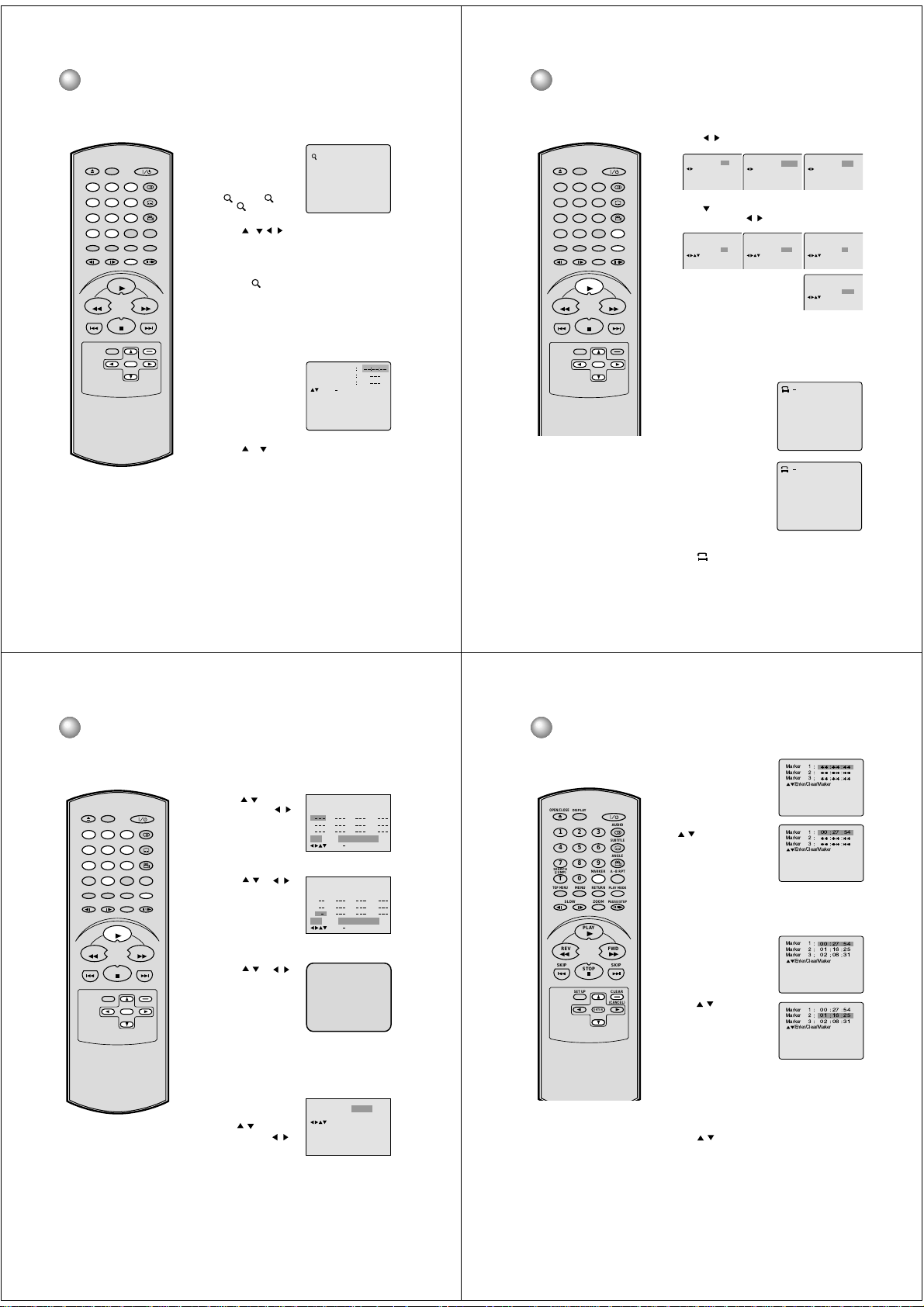
Marking desired scenes
The unit stores the points that you
want to watch again up to 3 points.
You can resume playback from
each scene.
DISPLAY
10
11
12
OPEN/CLOSE
79
SEARCH
(JUMP)
TOP MENU
REV FWD
SKIP
NOTES:
•
Some discs may not work with the
marking operation.
•
The marking is canceled when you
open the disc tray or turn the power off.
•
Some subtitles recorded around the
marker may fail to appear.
•
While the MARKER screen is displayed,
if you do a special playback as the
Fast Forward/Review Playback or
SKIP, the MARKER screen will
disappear. Press MARKER again as
soon as you find the desired scene.
MENU
SET UP
AUDIO
321
SUBTITLE
654
ANGLE
8
A - B RPTMARKER
0T
PLAY MODE
RETURN
PAUSE/STEP
ZOOMSLOW
PLAY
SKIP
STOP
CLEAR
(CANCEL)
ENTER
Marking the scenes
Press MARKER during
1
playback.
Select the blank Marker using
2
/ .
Then press ENTER at the desired scene.
• Repeat this procedure to set
the other 2 scenes.
Press MARKER to remove this display.
3
Returning to the scenes
Press MARKER during playback
1
or stop mode.
Press / to select the Marker
2
1-3.
Press ENTER.
3
Playback starts from the marked scene.
To cancel the mark
Press MARKER.
1
Press / to select the Marker 1-3.
2
Press CLEAR.
3
To remove this display, press MARKER.
27
Page 9
Changing soundtrack language/Setting the Spatializer/Subtitles
Changing soundtrack language
DISPLAY
OPEN/CLOSE
79
SEARCH
(JUMP)
TOP MENU
REV FWD
SKIP
Note:
•
If the desired language is not heard
after pressing the button several times,
the soundtrack language is not recorded
on the disc.
•
A selected soundtrack language may be
cancelled when you open the disc tray
or turn the power off. The initial default
language or available language will be
heard if the disc is played back again.
•
Depending on the DVD, you may not be
able to change subtitles, on turn subtitles on or off.
•
While playing a DVD, the subtitle may
change when: -you open or close the
disc tray.
•
In some cases, a selected subtitle language may not be changed immediately.
SET UP
AUDIO
321
SUBTITLE
654
ANGLE
8
A - B RPTMARKER
0T
PLAY MODE
RETURN
MENU
PAUSE/STEP
ZOOMSLOW
PLAY
SKIP
STOP
CLEAR
(CANCEL)
ENTER
28
You can select a desired language from a multilingual disc.
AUDIO
Press
1
2
Setting the Spatializer
You can enjoy virtual surround sound effects from your
stereo TV, on stereo system.
1
2
Subtitles
Turning the Subtitles On and Off
When playing back a disc recorded with subtitles, you
can turn the subtitles on or off.
Press SUBTITLE during playback until “Off” appears.
Changing the subtitle language
You can select the language when playing back a disc
recorded with multi-lingual subtitles.
1
2
during playback.
The current soundtrack
language will appear.
Press AUDIO repeatedly
until the desired language
is selected.
The on-screen display will
disappear after a few
seconds.
Press AUDIO during
playback. “Spatializer Off”
will appear.
Press or to select the
“Spatializer On”.
1/8 Eng DolbyDigital
Spatializer Off
2/8 Fra DolbyDigital
Spatializer Off
2/8 Fra DolbyDigital
Spatializer Off
2/8 Fra DolbyDigital
Spatializer On
Off
Press SUBTITLE repeatedly
during playback until your
desired language appears.
The on-screen display will disappear after a few seconds.
1/32 Eng
Changing angles/Title selection/DVD menu
Changing Angles
When playing back a disc recorded with multiple camera
angles,
you can change the angle that you are viewing.
Press ANGLE during play-
1
DISPLAY
OPEN/CLOSE
79
SEARCH
(JUMP)
TOP MENU
REV FWD
SKIP
Note:
•
Depending on the DVD, you may not be
able to change the angles even if multiangles are recorded on the DVD.
•
Depending on the DVD, you may not be
able to select the title. On some DVD’s
a "title menu" may simply be called a
"menu" or "top menu" in the instructions
supplied with the disc.
MENU
SET UP
AUDIO
321
SUBTITLE
654
ANGLE
8
A - B RPTMARKER
0T
PLAY MODE
RETURN
PAUSE/STEP
ZOOMSLOW
PLAY
SKIP
STOP
CLEAR
(CANCEL)
ENTER
back.
The current angle will ap-
pear.
Press ANGLE repeatedly until the desired angle is se-
2
lected.
Title Selection
Two or more titles may be recorded on some discs. If a title
menu is recorded on the disc, you can select the desired
title.
Press TOP MENU during playback.
1
Title menu appears on the screen.
Press / or / to select the desired title.
2
Press ENTER or PLAY.
3
The playback of the selected title will start.
DVD Menu
Some DVDs allow you to select the disc contents via the
disc menu.
When you play back these DVDs, you can select the
sub-title language and sound-track language, etc. from
the MENU.
Press MENU during playback.
1
The DVD menu appears on the screen.
• Press MENU again to resume playback at the scene
when you pressed MENU.
Press / or / to select the desired item.
2
Press ENTER.
3
The menu continues to another screen. Repeat steps 2
and 3 to set the item completely.
1/9
29
Setting the aspect ratio of TV screen
You can select an aspect ratio
appropriate to your TV.
DISPLAY
OPEN/CLOSE
79
SEARCH
(JUMP)
TOP MENU
REV FWD
SKIP
Note:
If the DVD disc is not formatted in the pan
& scan style, it will display a letterboxed
picture.
MENU
SET UP
AUDIO
321
SUBTITLE
654
ANGLE
8
A - B RPTMARKER
0T
PLAY MODE
RETURN
PAUSE/STEP
ZOOMSLOW
PLAY
SKIP
STOP
CLEAR
(CANCEL)
ENTER
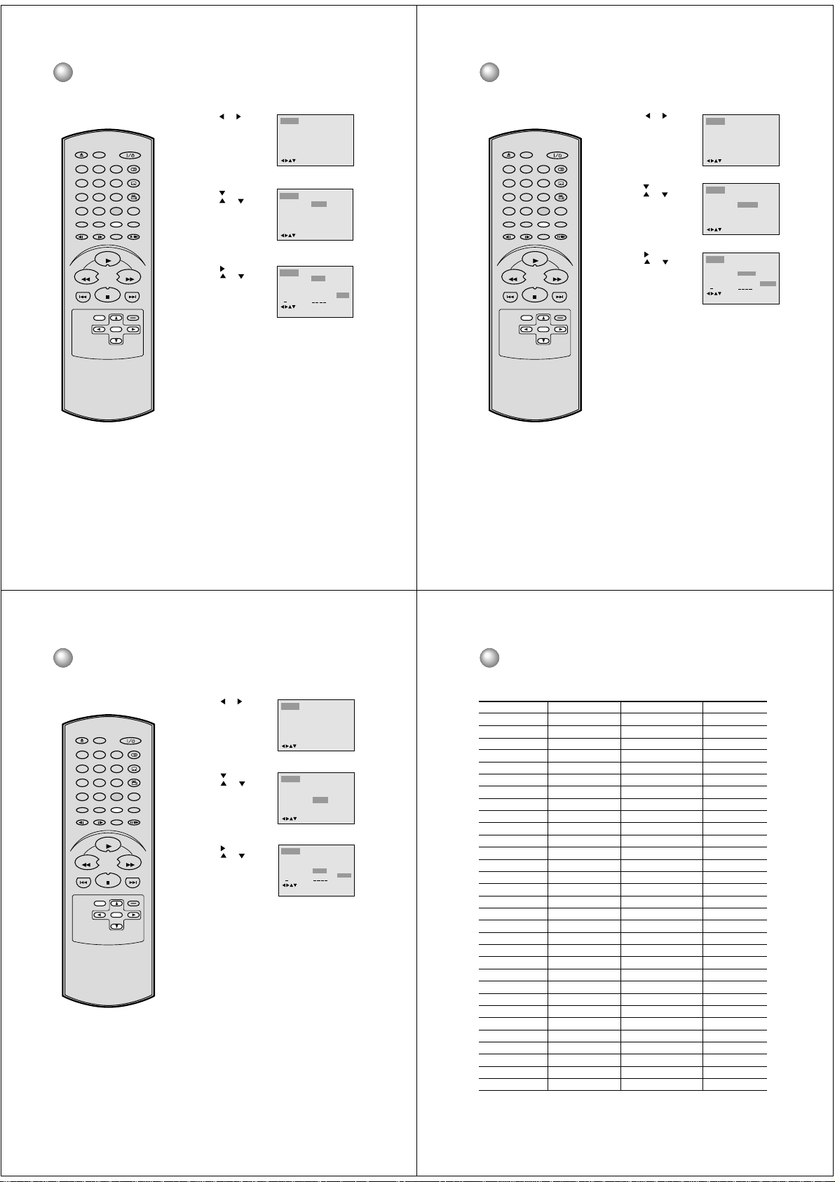
Press SET UP from the stop mode.
1
Press
or to select
“Picture”.
Press or ENTER, then
2
or to select
press
“Tv Screen”.
Press or ENTER.
3
or to select
Press
your desired screen type,
then press ENTER.
You have the following screen sizes to choose from:
4:3
Select this mode when connecting to a conventional TV.
When playing back a wide screen-DVD disc, it displays
the wide picture with black bands at the top and bottom of
screen.
PAN SCAN (Conventional mode)
4:3
Displays the wide picture on the whole screen with left
and right edges automatically cut off.
WIDE SCREEN
16:9
Select this mode when connecting to a wide-screen TV.
A wide screen picture is displayed full size.
To exit the SETUP menu, press SET UP or RETURN.
4
Language Picture Parental OtherSound
/Enter/Setup/Return
Language Picture Parental OtherSound
4:3
Tv Screen
On
Display
/Enter/Setup/Return
Language Picture Parental OtherSound
4:3
Tv Screen
On
Display
/Enter/Setup/Return
Setting on Screen display/Disc status
Setting on Screen display
On screen display can be viewed when you press the
operation buttons.
Press SET UP from the
1
stop mode.
or to select
Press
DISPLAY
OPEN/CLOSE
79
SEARCH
(JUMP)
TOP MENU
4:3
4:3
16:9
REV FWD
SKIP
MENU
SET UP
AUDIO
321
SUBTITLE
654
ANGLE
8
A - B RPTMARKER
0T
PLAY MODE
RETURN
PAUSE/STEP
ZOOMSLOW
PLAY
SKIP
STOP
CLEAR
(CANCEL)
ENTER
“Picture”.
Press or ENTER,
2
then
or to select
press
“Display”.
Press / or ENTER to
3
select “On” or “Off”.
On: On screen displays appear when you press the
operation buttons (factory setting).
Off: On screen displays do not appear when operation
buttons are pressed.
To exit the SETUP screen, press SET UP or RETURN while
4
the SETUP screen is displayed.
Disc status
With each Press of DISPLAY, the status of the disc will appear on
the screen and change as follows.
DVD
00:34:56 01:12:33
To exit the display, press DISPLAY again.
CD
34:56 71:33
Track 11/18
Language Picture Parental OtherSound
/Enter/Setup/Return
Language Picture Parental OtherSound
4:3
Tv Screen
On
Display
/Enter/Setup/Return
Language Picture Parental OtherSound
4:3
Tv Screen
Off
Display
/Enter/Setup/Return
Title 1/99
Chapter 1/999
1/8
Eng DolbyDigital
1/32
Eng
00:34:56 01:12:33
1/9
30
When you playback a CD disc, the status display will
appear and remain on the screen.
31
Page 10

Dynamic Range Control
DRC (Dynamic Range Control) reduces the range between the quietest
and loudest scenes on the disc.
DISPLAY
OPEN/CLOSE
79
SEARCH
(JUMP)
TOP MENU
REV FWD
SKIP
Note:
• This function works only during
playback of Dolby Digital recorded discs.
• The level of Dynamic Range Reduction
may differ depending on DVD video disc.
SET UP
AUDIO
321
SUBTITLE
654
ANGLE
8
A - B RPTMARKER
0T
PLAY MODE
RETURN
MENU
PAUSE/STEP
ZOOMSLOW
PLAY
SKIP
STOP
CLEAR
(CANCEL)
ENTER
32
Press SET UP from the stop mode.
1
Press
or to select
“Sound”.
Press
or ENTER to
2
select “DRC”.
Press or ENTER, then
3
press
or to select
desired setting.
Max: Level difference is big.
Std: Level difference is medium.
Min: Level difference is small.
Language Picture Parental OtherSound
/Enter/Setup/Return
Language Picture Parental OtherSound
Std
DRC
/Enter/Setup/Return
Language Picture Parental OtherSound
Std
DRC
/Enter/Setup/Return
Parental control setting
Some discs are specified as not suitable for children. Playback of such
discs can be restricted with this unit.
DISPLAY
OPEN/CLOSE
79
SEARCH
(JUMP)
TOP MENU
Max
Std
Min
REV FWD
SKIP
Note:
• When each setup function (P.30~31,
33~38) has been completed, the unit
can always be operated under the
same conditions (especially with
DVD discs).
Each setup command will be
retained in the memory even if you
turn the power off.
• Depending on the discs, the unit may not
be able to limit playback.
• Some discs may not be encoded with
specific rating level information though its
disc jacket says "adult." For those discs,
the parental control feature will not work.
MENU
SET UP
AUDIO
321
SUBTITLE
654
ANGLE
8
A - B RPTMARKER
0T
PLAY MODE
RETURN
PAUSE/STEP
ZOOMSLOW
PLAY
SKIP
STOP
CLEAR
(CANCEL)
ENTER
Press SET UP from the stop mode.
1
or to select
Press
“Parental”. Then press
or ENTER.
Press
or to select
2
“Parental”, then press
or until the level you require appears.
• Level Off : The parental control setting does not
function.
• Level 8 : Virtually all DVD software can be played
back.
• Level 1 : DVD software for adults cannot be
played back.
• Select from level 1 to level 8. The limitation will be
more severe as the level number decreases.
Press or to select
3
“Password”.
Press number buttons
(0-9) to input a 4-digit
password.
Be sure to remember this
number!
• If you input a wrong
number, press CLEAR
(CANCEL).
Press ENTER to store the
4
password.
Note: Now the rating is
locked and the setting cannot be changed unless you
enter the correct password.
Press SET UP or RETURN to exit the parental control
5
screen.
Language
Picture Parental Other
Sound
Password
Off
Parental
0 9/Clear
/Enter/Setup/Return
Language Picture Parental OtherSound
Password
1
Parental
/Enter/Setup/Return
Language Picture Parental OtherSound
2 3
1
Password
1
Parental
0 9/Clear
/Enter/Setup/Return
Language Picture Parental OtherSound
Password
1
Parental
0 9/Clear
/Enter/Setup/Return
4
33
T o change the parental level
1
DISPLAY
OPEN/CLOSE
79
SEARCH
(JUMP)
TOP MENU
REV FWD
SKIP
SET UP
AUDIO
321
SUBTITLE
654
ANGLE
8
A - B RPTMARKER
0T
PLAY MODE
RETURN
MENU
PAUSE/STEP
ZOOMSLOW
PLAY
SKIP
STOP
CLEAR
(CANCEL)
ENTER
2
3
4
5
If you forget the password...
1. Press OPEN/CLOSE to open the disc tray.
2. Remove the disc.
3. Press OPEN/CLOSE again to close the
tray. “No Disc” appears on the TV screen.
4. While holding STOP down on the front
panel, press 7 on the remote control.
“PASSWORD CLEAR” appears on the
TV screen.
5. Enter a new password again.
34
6
7
Press SET UP from the stop
or to select
Press
“Parental”. Then press
or ENTER.
Press number buttons
(0-9) to enter the password
you have stored.
Press ENTER.
The rating is now unlocked.
Press or to select
“Parental”, then press
to change the parental
level.
Press or to select
“Password”, then press
number buttons (0-9) to
enter the password.
Note: You can change the
password at this time if you
want.
Press ENTER.
The parental level is
changed and locked.
Press SET UP or RETURN
to exit the parental control
screen.
or
mode.
Language Picture Parental OtherSound
Password
Parental
0 9/Clear
/Enter/Setup/Return
Language Picture Parental OtherSound
1 2 3 4
Password
Parental
0 9/Clear
/Enter/Setup/Return
Language Picture Parental OtherSound
Password
Parental
0 9/Clear
/Enter/Setup/Return
Language Picture Parental OtherSound
Password
Parental
/Enter/Setup/Return
Language Picture Parental OtherSound
1 2 3 4
Password
Parental
0 9/Clear
/Enter/Setup/Return
Language Picture Parental OtherSound
Password
Parental
0 9/Clear
/Enter/Setup/Return
Temporary disabling of rating level of DVD disc
Some DVD discs may permit you to
temporarily cancel the rating level
that you have set.
It is up to you to decide whether on
1
1
1
5
5
5
not to cancel the rating level.
DISPLAY
OPEN/CLOSE
79
SEARCH
(JUMP)
TOP MENU
REV FWD
SKIP
Note:
This temporary cancellation of rating level
will be maintained until the disc is ejected.
When the disc is ejected, the original rating
level will be set again automatically.
MENU
SET UP
AUDIO
321
SUBTITLE
654
ANGLE
8
A - B RPTMARKER
0T
PLAY MODE
RETURN
PAUSE/STEP
ZOOMSLOW
PLAY
SKIP
STOP
CLEAR
(CANCEL)
ENTER
Load a DVD disc and press
1
PLAY or OPEN/CLOSE on
the unit (see P.21).
If the DVD disc has been designed to temporarily cancel the
2
Rating level, the screen which follows the “Reading” screen
will change, depending on which disc is played. If you select
“YES” with the SELECT key, “Your disc exceeds the
parental control level#.” screen will then appear.
Reading
If you wish to cancel the set rating level temporarily, select
3
“Parental Control Level” with
If the 4-digit password at step 3 on P.32 has been set, the
password entering screen will appear as shown in step 4
below.
Alternatively, if the password has not been set, playback
will commence. If you don’t know (or have forgotten) the
password, select “Cancel Picture”.
The setting screen will disappear. Press OPEN/CLOSE to
remove the disc.
Enter the password with
4
number buttons (0-9).
Then press ENTER.
If you interrupt the entering, press RETURN.
Playback will commence if the entered password was
5
correct.
Your disc exceeds
the parental control level#.
Parental Control Level
Cancel Picture
/Enter/Return
or , then press ENTER.
Please enter the
-
4 digit password
9/ Clear/ReturnEnter/0
35
Page 11
Setting menu language
You can select the language of the
DVD disc menu display.
DISPLAY
OPEN/CLOSE
79
SEARCH
(JUMP)
TOP MENU
REV FWD
SKIP
SET UP
AUDIO
321
SUBTITLE
654
ANGLE
8
A - B RPTMARKER
0T
PLAY MODE
RETURN
MENU
PAUSE/STEP
ZOOMSLOW
PLAY
SKIP
STOP
CLEAR
(CANCEL)
ENTER
Press SET UP from the stop mode.
1
Press
or to select
“Language”.
Press
or ENTER, then
2
press
or to select
“Menu”.
Press or ENTER.
3
Press
or to select
your desired language,
then press ENTER.
English, Francais, Espanol
The selected language is the first-priority Menu language.
Other: Other language can be selected (See the Lan-
guage Code List on page 39).
To exit the SETUP screen, press SET UP or RETURN while
4
the SETUP screen is displayed.
Language Picture Parental OtherSound
/Enter/Setup/Return
Language Picture Parental OtherSound
Menu
English
Subtitle
Automatic
Audio
English
/Enter/Setup/Return
Language Picture Parental OtherSound
Menu
English
Subtitle
Automatic
Audio
English
0 9/Clear
/Enter/Setup/Return
English
Francais
Espanol
Other
Setting subtitle language
The same subtitle language can
always be selected even if you replace
the disc or turn the power off.
DISPLAY
OPEN/CLOSE
79
SEARCH
(JUMP)
TOP MENU
REV FWD
SKIP
Note:
If the selected language is not recorded
on the disc, the first-priority language is
selected.
SET UP
AUDIO
321
SUBTITLE
654
ANGLE
8
A - B RPTMARKER
0T
PLAY MODE
RETURN
MENU
PAUSE/STEP
ZOOMSLOW
PLAY
SKIP
STOP
CLEAR
(CANCEL)
ENTER
Press SET UP from the stop mode.
1
Press
or to select
“Language”.
Press
or ENTER, then
2
press
or to select
“Subtitle”.
Press or ENTER.
3
Press
or to select
your desired language,
then press ENTER.
English, Francais, Espanol
The subtitle is displayed with the selected language if it is
recorded on the disc.
Other:
If you want to select another language, enter the language
code (see the language code list on page 39).
Automatic:
• The unit will automatically select the same language
chosen for the AUDIO setting.
• When the same language as the AUDIO is recorded on
the disc, the subtitles will not appear during playback.
• When the same language as the AUDIO is not recorded
on the disc, the subtitles will appear during playback.
Off:
Subtitles do not appear.
To exit the SETUP screen, press SET UP or RETURN while
4
the SETUP screen is displayed.
Language Picture Parental OtherSound
/Enter/Setup/Return
Language Picture Parental OtherSound
Menu
English
Subtitle
Automatic
Audio
English
/Enter/Setup/Return
Language Picture Parental OtherSound
Menu
English
Subtitle
Automatic
Audio
English
0 9/Clear
/Enter/Setup/Return
English
Francais
Espanol
Other
Automatic
Off
36
Setting audio soundtrack language
The same audio soundtrack language
can always be selected by your unit
even if you replace the disc or turn the
power off.
DISPLAY
OPEN/CLOSE
79
SEARCH
(JUMP)
TOP MENU
REV FWD
SKIP
Note:
If the selected language is not recorded
on the disc, the original language will be
heard.
SET UP
AUDIO
321
SUBTITLE
654
ANGLE
8
A - B RPTMARKER
0T
PLAY MODE
RETURN
MENU
PAUSE/STEP
ZOOMSLOW
PLAY
SKIP
STOP
CLEAR
(CANCEL)
ENTER
Press SET UP from the stop mode.
1
Press
or to select
“Language”.
or ENTER, then
Press
2
press
or to select
“Audio”.
Press or ENTER.
3
Press
or to select
your desired Audio Language, then press ENTER.
• English, Francais, Espanol:
The language you have selected will play if it is
recorded on the disc.
• Other: If you want to select another language,
enter the language code (See the Language Code List
on page 39).
• Original: The unit will select the first priority language
of each disc.
To exit the SETUP screen, press SET UP or RETURN while
4
the SETUP screen is displayed.
Language Picture Parental OtherSound
/Enter/Setup/Return
Language Picture Parental OtherSound
Menu
English
Subtitle
Automatic
Audio
English
/Enter/Setup/Return
Language Picture Parental OtherSound
Menu
English
Subtitle
Automatic
Audio
English
0 9/Clear
/Enter/Setup/Return
English
Francais
Espanol
Other
Original
Language code list
Enter the appropriate code number for the initial settings "AUDIO", "SUBTITLE" and/or "MENU LANGUAGE"
(see pages 36-38).
Language Name Code Language Name Code Language Name Code
Abkhazian 1112 Fiji 1620 Lingala 2224 Singhalese 2919
Afar 1111 Finnish 1619 Lithuanian 2230 Slovak 2921
Afrikaans 1116 French 1628 Macedonian 2321 Slovenian 2922
Albanian 2927 Frisian 1635 Malagasy 2317 Somali 2925
Amharic 1123 Galician 1722 Malay 2329 Spanish 1529
Arabic 1128 Georgian 2111 Malayalam 2322 Sundanese 2931
Armenian 1835 German 1415 Maltese 2330 Swahili 2933
Assamese 1129 Greek 1522 Maori 2319 Swedish 2932
Aymara 1135 Greenlandic 2122 Marathi 2328 Tagalog 3022
Azerbaijani 1136 Guarani 1724 Moldavian 2325 Tajik 3017
Bashkir 1211 Gujarati 1731 Mongolian 2324 Tamil 3011
Basque 1531 Hausa 1811 Nauru 2411 Tatar 3030
Bengali; Bangla 1224 Hebrew 1933 Nepali 2415 Telugu 3015
Bhutani 1436 Hindi 1819 Norwegian 2425 Thai 3018
Bihari 1218 Hungarian 1831 Oriya 2528 Tibetan 1225
Breton 1228 Icelandic 1929 Panjabi 2611 Tigrinya 3019
Bulgarian 1217 Indonesian 1924 Pashto, Pushto 2629 Tonga 3025
Burmese 2335 Interlingua 1911 Persian 1611 Turkish 3028
Byelorussian 1215 Irish 1711 Polish 2622 Turkmen 3021
Cambodian 2123 Italian 1930 Portuguese 2630 Twi 3033
Catalan 1311 Japanese 2011 Quechua 2731 Ukrainian 3121
Chinese 3618 Javanese 2033 Rhaeto-Romance 2823 Urdu 3128
Corsican 1325 Kannada 2124 Romanian 2825 Uzbek 3136
Croatian 1828 Kashmiri 2129 Russian 2831 Vietnamese 3219
Czech 1329 Kazakh 2121 Samoan 2923 Volapük 3225
Danish 1411 Kirghiz 2135 Sanskrit 2911 Welsh 1335
Dutch 2422 Korean 2125 Scots Gaelic 1714 Wolof 3325
English 1524 Kurdish 2131 Serbian 2928 Xhosa 3418
Esperanto 1525 Laothian 2225 Serbo-Croatian 2918 Yiddish 2019
Estonian 1530 Latin 2211 Shona 2924 Yoruba 3525
Faroese 1625 Latvian, Lettish 2232 Sindhi 2914 Zulu 3631
Language Name Code
37
38
39
Page 12
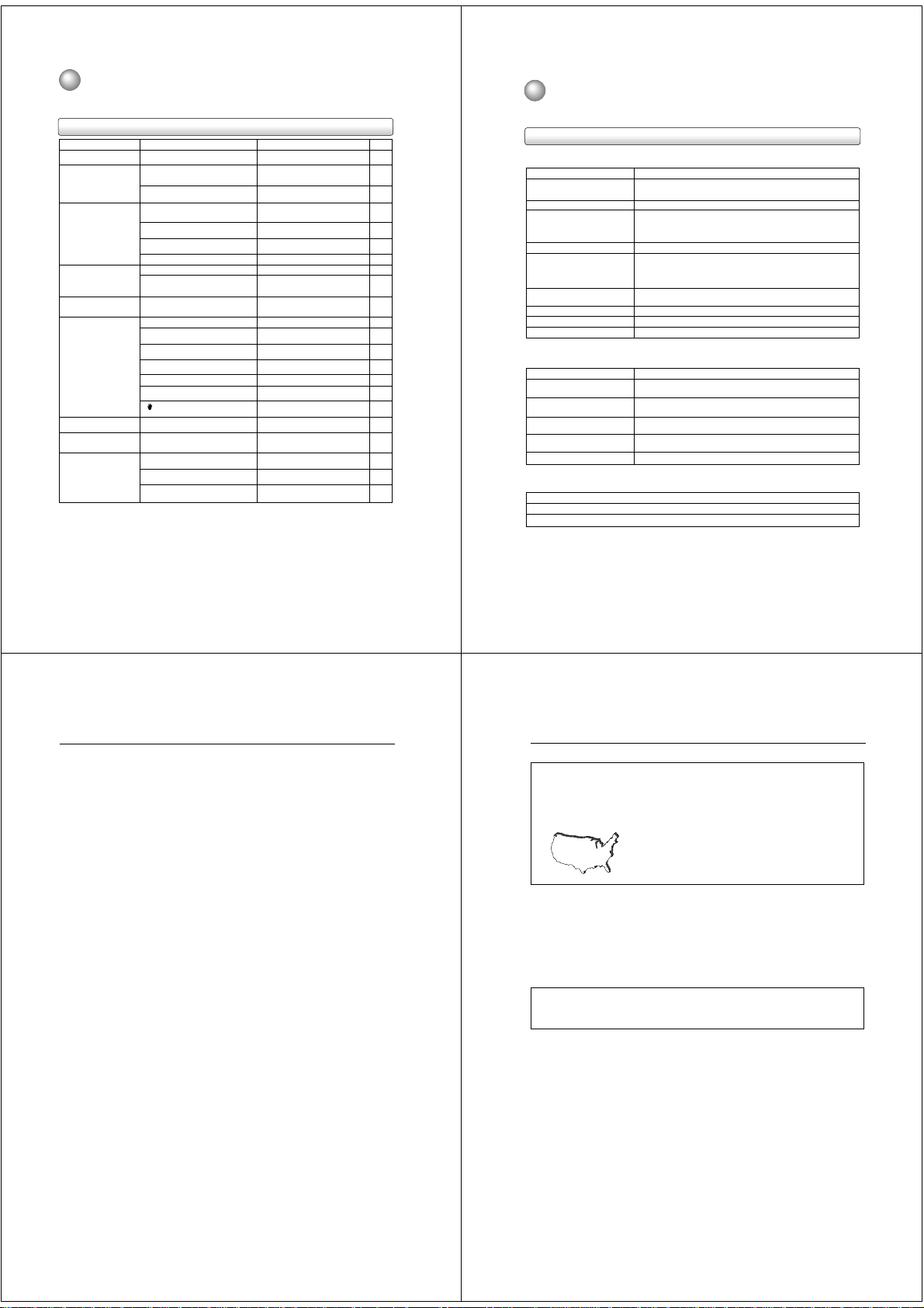
Before Calling Service Personnel
Check the following guide for the possible cause of a problem before contacting service.
Symptoms and correction
Symptom
No power.
No picture.
No sound.
The playback picture has
occasional distortion.
Brightness is unstable or
noises are present in the
playback pictures.
The DVD video player does
not start playback.
Playback does not follow the
course of the disc’s program.
Buttons do not work.
The remote control does not
work properly.
Cause
• The power plug is disconnected.
• The TV is not set to receive DVD signal
output.
• The video cable is not connected securely.
• The equipment connected with the audio
cable is not set to receive DVD signal
output.
• The audio cable is not connected securely.
• The audio receiver or TV is turned off.
• The unit is in the special playback mode.
• The disc is dirty.
• It is in fast forward or fast reverse
playback.
• The effect of copy protection.
• No disc is inserted.
• An unplayable disc is inserted.
• The disc is placed upside down.
• The disc is not placed within the guide.
• The disc is dirty.
• The parental lock function is set.
appears on the screen.
•
• It is in the mode of repeat playback,
program playback, etc.
• Power supply fluctuations or other
abnormalities such as static electricity
may interrupt correct operations.
• The remote control is not pointed at the
remote sensor of the DVD video player.
• The remote control is too far from the DVD
video player.
• The batteries in the remote control are
exhausted.
Correction
• Connect the power plug securely into the
wall outlet.
• Select the appropriate video input mode
on the TV so the picture from the DVD
video player appears on the TV screen.
• Connect the video cable securely into the
appropriate jacks.
• Select the correct input mode of the
audio receiver so you can listen to the
sound from the DVD video player.
• Connect the audio cable securely into the
appropriate jacks.
• Turn on the equipment connected with
the audio cable.
• Resume the normal playback.
• Eject the disc and clean it.
• Sometimes a small amount of picture
distortion may appear. This is not a
malfunction.
• Connect the DVD video player directly to
the TV. Avoid connecting the DVD video
player to a VCR or TV/VCR combination.
• Insert a disc.
• Insert a playable disc. (Check the disc
type and color system.)
• Place the disc with the playback side
down.
• Place the disc correctly inside the guide
on the disc tray.
• Clean the disc.
• Cancel the parental lock function or
change the parental lock level.
• The function is prohibited with the unit or
the disc.
• These operations may prevent a proper
progress of the contents.
• Turn the power on or off with POWER.
Or disconnect the power plug and insert
it into the wall outlet again.
• Point the remote control at the remote
sensor of the DVD video player.
• Operate the remote control within about
7 m.
• Replace the batteries with new ones.
16, 17
16, 17
18, 19
Page
Specifications
DVD video player / outputs / supplied accessories
16
20
–
–
22
9
–
16
21
10
21
21
9
34
10
–
–
15
15
15
DVD Video Player
Power supply 120 V AC, 60 Hz
Power consumption Operation : 10 W
Mass 4.4 lbs (2.0 kg)
External dimensions Width : 16 - 15/16 inches (430mm)
Signal system Standard NTSC
Pickup CD : Wavelength: 775 - 815 nm
Frequency response DVD : 4 Hz
Harmonic distortion Less than 0.008 %
Wow and flutter Below measurable level
Operating conditions Temperature: 5 °C to 40 °C, Operation status: Horizontal
Outputs
Video output 1.0 V (p-p), 75 Ω, negative sync., pin jack × 1
S video output (Y) 1.0 V (p-p), 75 Ω, negative sync., Mini DIN 4-pin × 1
Component video output (Y) 1.0 V (p-p), 75 Ω, negative sync., pin jack × 1
Audio output (BITSTREAM/PCM 0.5V (p-p), 75 Ω, pin jack × 1
COAXIAL)
Audio output (BITSTREAM/PCM Optical connector × 1
OPTICAL)
Audio output (ANALOG) 2.0 V (rms), 220 Ω, pin jacks (L, R) × 1
Supplied Accessories
Audio/video cable ................................................. 1
Remote control ..................................................... 1
Batteries (AAA) ..................................................... 2
Standby : 4 W
Height : 2 - 5/16 inches (59mm)
Depth : 8 - 1/8 inches (206.5mm)
Maximum output power: 0.5 mW
DVD : Wavelength: 650 - 666 nm
Maximum output power: 2.0 mW
-
22 kHz
CD : 4 Hz
-
20 kHz
(C) 0.286 V (p-p), 75 Ω
(P
B)/(PR) 0.525 V (p-p), 75 Ω, pin jack × 2
• Designs and specifications are subject to change without notice.
40
LIMITED WARRANTY DVD VIDEO PLA YER
Toshiba America Consumer Products, Inc. (“TACP”), Toshiba Hawaii (“THI”) and Toshiba Canada Limited (“TCL”) make the
following limited warranties. These limited warranties extend to original purchaser or any person receiving this set as a gift from
the original purchaser and to no other purchaser or transferee.
Limited Ninety (90) Day Warranty
TACP/THI warrant this product against defects in materials
or workmanship for a period of ninety (90) days after the
date of original retail purchase. During this period, TACP/
THI will repair or replace a defective product or part, at their
option, with a new or refurbished product or part without
charge to you. You must deliver the entire product to a
TACP/THI Authorized Service Station. You are responsible
for all transportation and insurance charges for the unit to
and from the Authorized Service Station. If you live in the
U.S.A. you may, at your option, return your DVD Unit to:
Toshiba America Consumer Products Inc.
Returns Center
1420C Toshiba Dr.
Lebanon, TN 37087
Upon receipt we will, at our option, exchange the DVD Unit
with a new or refurbished unit. Canadian consumers are
requested to contact TCL. In Hawaii consumers are
requested to contact THI.
Limited One (1) Year Warranty
TACP/THI further warrant the parts in this product against
defects in materials or workmanship for a period of one (1)
year after the date of original retail purchase. During this
period, TACP/THI will repair or replace a defective product
or part, at their option, with a new or refurbished product or
part without charge to you, except that if a defective part is
replaced after ninety (90) days from the date of the original
retail purchase you pay labor charges involved in the
replacement. You must also deliver the entire product to a
TACP/THI Authorized Service Station. You are responsible
for all transportation and insurance charges for the unit to
and from the Authorized Service Station. If you live in the
U.S.A. you may, at your option, return your DVD Unit to:
Toshiba America Consumer Products Inc.
Returns Center
1420C Toshiba Dr.
Lebanon, TN 37087
Upon receipt we will, at our option, exchange the DVD Unit
with a new or refurbished unit. Canadian Consumers are
requested to contact TCL. In Hawaii consumers are
requested to contact THI.
Rental Units
The warranty for rental units begin with the first rental or
thirty (30) days from the date of shipment to the rental firm,
whichever comes first.
Commercial Units
Products sold and used for commercial use have a limited
ninety (90) day warranty for all parts and labor.
Owner’s Manual
You should read the owner’s manual thoroughly before
operating this product. You should complete and mail the
enclosed Demographic card within ten (10) days after you,
or the person who has given you this product as a gift,
purchased this product. This is one way to enable TACP to
provide you with better customer service and improved
products. Failure to return the card will not affect your rights
under this warranty.
Your Responsibility
The above warranties are subject to the following
conditions:
(1) You must retain your bill of sale or provide other proof of
purchase.
(2) You must notify a TACP/THI/TCL /Authorized Service
Station within thirty (30) days after you discover a
defective product or part.
(3) All warranty servicing of this product must be made by a
TACP/THI/TCL Authorized Service Station.
(4) U.S.A. warranties are effective only if the product is
purchased and operated in the Continental U.S.A. or
Puerto Rico.
(5) Labor service charges for set installation. Set up,
adjustment of customer controls and installation or
repair of antenna systems are not covered by this
warranty. Reception problems caused by inadequate
antenna systems are your responsibility.
(6) Warranties extend only to defects in materials or
workmanship as limited above and do not extend to any
product or parts which have been lost or discarded by
you or to damage to products or parts caused by
misuse, accident, damage caused by Acts of God, such
as lighting or fluctuations in electric power, improper
installation, improper maintenance or use in violation of
instructions furnished by us; or to units which have been
altered or modified without authorization of TACP/THI/
TCL or to damage to products or part thereof which
have had the serial number removed, altered, defaced
or rendered illegible.
(7) Should you elect to return your DVD Unit to TACP after
the ninety (90) days and within one (1) year, or after the
warranty period has expired: Call (800)-631-3811 to
receive information concerning an exchange price.
Payment must be enclosed with product in the form of a
certified check or money order including reason for
return.
(8) Physically damaged DVD Units are not acceptable for
repair or exchange whether in or out of warranty and
will be returned as received.
(Continued)
41
LIMITED WARRANTY DVD VIDEO PLAYER (continued)
How to Obtain Warranty Service
(1) Refer to the troubleshooting guide in your owner’s manual. This check list may solve your problem.
(2) In the U.S.A., only call the TACP toll free number 800-631-3811, or if in Hawaii or Canada see listing below within (30)
days after you find a defective product or part.
(3) Arrange for the delivery of the product to the TACP/THI/TCL Authorized Service Station or TACP Return Center.
Products shipped to the Service Station must be insured and safely and securely packed, preferably in the original
shipping carton, and a letter explaining the defect and also a copy of the bill of sale or other proof of purchase must be
enclosed.
In the Continental United States contact:
Toll Free
800-631-3811
All warranties implied by state law, including the implied warranties of merchantability and fitness for a particular purpose, are
expressly limited to the duration of the limited warranties set forth above. With the exception of any warranties implied by state
law as hereby limited, the foregoing warranty is exclusive and in lieu of all other warranties, guarantees, agreements and
similar obligations of manufacturer or seller with respect to the repair or replacement of any parts. In no event shall TACP/THI
be liable for consequential or incidental damages.
No person, agent, distributor, dealer or company is authorized to change, modify or extend the terms of these warranties in
any manner whatsoever. The time within which an action must be commenced to enforce any obligation of T ACP/THI arising
under the warranty or under any statute, or law of the United States or any state thereof, is hereby limited to ninety (90) days
from the date you discover or should have discovered, the defect. This limitation does not apply to implied warranties arising
under state law.
This warranty gives you specific legal rights and you may also have other rights which may vary from state to state. Some
states do not allow limitation on how long an implied warranty lasts, when an action may be brought, or the exclusion or
limitation of incidental or consequential damages, so the above provisions may not apply to you.
ATTENTION CANADIAN CONSUMERS:
Canadian consumers are requested to complete the special Canadian “Warranty Registration Form” enclosed, and forward
this completed form with a copy of bill of sale to TOSHIBA OF CANADA to “Register and Validate” their warranty. Product
must be purchased from an Authorized Canadian Dealer. Products purchased in the U.S.A. and used in Canada are not
covered by these warranties.
IMPORTANT : PACKING AND SHIPPING INSTRUCTION
When you send the product to a Service Station, you must use the original carton box and packing material, then insert the
original carton box containing the unit into another carton using more packing material.
In Hawaii contact:
Toshiba Hawaii Inc.
327 Kamakee Street
Honolulu, HA 96814
(808)-521-5377
In Canada contact:
Consumer Electronics Group
191 McNabb Street
Markham, Ontario L3R 8H2
(905)-470-5400
Consumer Electronics Group
1643 North Service Road
Droval, QC H9P 1J1
(514)-856-4100
Consumer Electronics Group
22171 Fraserwood Way
Richmond, B.C. V6W 1J5
(604)-303-2500
42
43
Page 13
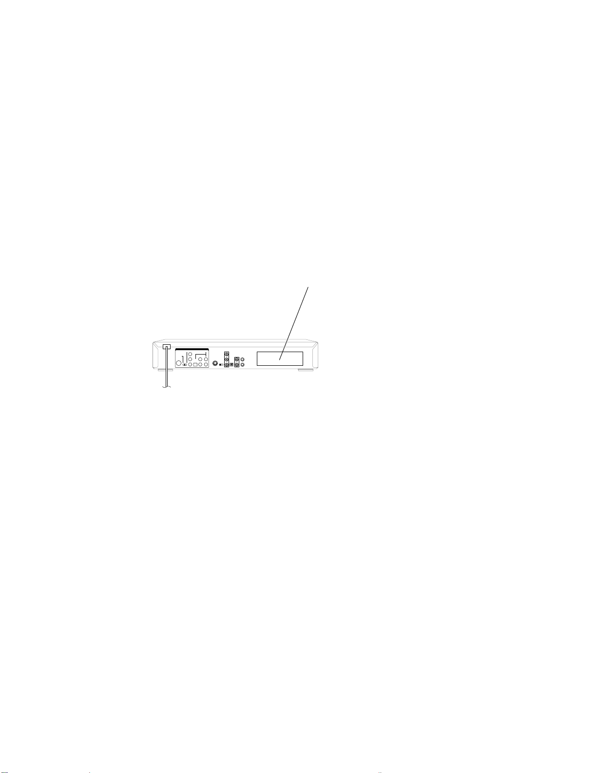
CAUTION
THIS DIGITAL VIDEO PLAYER EMPLOYS A LASER SYSTEM.
TO ENSURE PROPER USE OF THIS PRODUCT, PLEASE READ THIS SERVICE MANUAL CARE-
FULLY AND RETAIN FOR FUTURE REFERENCE. SHOULD THE UNIT REQUIRE MAINTENANCE,
CONTACT AN AUTHORIZED SERVICE LOCATION-SEE SERVICE PROCEDURE.
USE OF CONTROLS, ADJUSTMENTS OR THE PERFORMANCE OF PROCEDURES OTHER THAN
THOSE SPECIFIED HEREIN MAY RESULT IN HAZARDOUS RADIATION EXPOSURE.
TO PREVENT DIRECT EXPOSURE TO LASER BEAM, DO NOT TRY TO OPEN THE ENCLOSURE.
VISIBLE LASER RADIA TION MAY BE PRESENT WHEN THE ENCLOSURE IS OPENED. DO NOT
ST ARE INTO BEAM.
Location of the required Marking
The rating sheet and the safety caution are on the rear of the unit.
CERTIFICATION: COMPLIES WITH FDA
RADIA TION PERFORMANCE STANDARDS,
21 CFR SUBCHAPTER J.
A1-1
Page 14

IMPORTANT SAFEGUARDS
1.
READ INSTRUCTIONS
All the safety and operating instructions should be read before the unit is operated.
2.
RETAIN INSTRUCTIONS
The safety and operating instructions should be retained for future reference.
3.
HEED WARNINGS
All warnings on the unit and in the operating instructions should be adhered to.
4.
FOLLOW INSTRUCTIONS
All operating and use instructions should be followed.
5.
CLEANING
Unplug this unit from the wall outlet before cleaning. Do not use liquid cleaners or aerosol cleaners. Use a damp cloth for cleaning.
6.
ATTACHMENTS
Do not use attachments not recommended by the unit’s manufacturer as they may cause hazards.
7.
WATER AND MOISTURE
Do not use this unit near water. For example, near a bathtub, washbowl, kitchen sink, or laundry tub, in a wet basement, or near a
swimming pool.
8.
ACCESSORIES
Do not place this unit on an unstable cart, stand, tripod, bracket, or table. The unit may fall,
causing serious injury, and serious damage to the unit. Use only with a cart, stand, tripod,
bracket, or table recommended by the manufacturer.
8A.
An appliance and cart combination should be moved with care. Quick stops, excessive force,
and uneven surfaces may cause the appliance and cart combination to overturn.
9.
VENTILATION
Slots and openings in the cabinet and in the back or bottom are provided for ventilation, to ensure reliable operation of the unit, and
to protect it from overheating. These openings must not be blocked or covered. The openings should never be blocked by placing
the unit on a bed, sofa, rug, or other similar surface. This unit should never be placed near or over a radiator or heat source. This
unit should not be placed in a built-in installation such as a bookcase or rack unless proper ventilation is provided or the manufacturer’s instructions have been adhered to.
10.
POWER SOURCES
This unit should be operated only from the type of power source indicated on the rating plate. If you are not sure of the type of
power supply to your home, consult your appliance dealer or local power company. For units intended to operate from battery
power, or other sources, refer to the operating instructions.
11.
GROUNDING OR POLARIZATION
This unit is equipped with a polarized alternating-current line plug (a plug having one blade wider than the other). This plug will fit
into the power outlet only one way. This is a safety feature. If you are unable to insert the plug fully into the outlet, try reversing the
plug. If the plug should still fail to fit, contact your electrician to replace your obsolete outlet. Do not defeat the safety purpose of the
polarized plug. If your unit is equipped with a 3-wire grounding-type plug, a plug having a third (grounding) pin, this plug will only fit
into a grounding-type power outlet. This too, is a safety feature. If you are unable to insert the plug into the outlet, contact your
electrician to replace your obsolete outlet. Do not defeat the safety purpose of the grounding-type plug.
12.
POWER-CORD PROTECTION
Power-supply cords should be routed so that they are not likely to be walked on or pinched by items placed upon or against them,
paying particular attention to cords at plugs, convenience receptacles, and the point where they exit from the appliance.
13.
LIGHTNING
To protect your unit from a lightning storm, or when it is left unattended and unused for long periods of time, unplug it from the wall
outlet and disconnect the antenna or cable system. This will prevent damage to the unit due to lightning and power line surges.
14.
POWER LINES
An outside antenna system should not be located in the vicinity of overhead power lines or other electric light or power circuits, or
where it can fall into such power lines or circuits. When installing an outside antenna system, extreme care should be taken to keep
from touching such power lines or circuits, as contact with them might be fatal.
15.
OVERLOADING
Do not overload wall outlets and extension cords, as this can result in a risk of fire or electric shock.
16.
OBJECT AND LIQUID ENTRY
Do not push objects through any openings in this unit, as they may touch dangerous voltage points or short out parts that could
result in fire or electric shock. Never spill or spray any type of liquid into the unit.
17.
OUTDOOR ANTENNA GROUNDING
If an outside antenna or cable system is connected to the unit, be sure the antenna or cable system is grounded so as to provide
some protection against voltage surges and built-up static charges. Section 810 of the National Electrical Code, ANSI/NFPA 70,
provides information with respect to proper grounding of the mast and supporting structure, grounding of the lead-in wire to an
antenna discharge unit, size of grounding conductors, location of antenna discharge unit, connection to grounding electrodes, and
requirements for the grounding electrode.
18.
SERVICING
Do not attempt to service this unit yourself as opening or removing covers may expose you to dangerous voltage or other hazards.
Refer all servicing to qualified service personnel.
PORT ABLE CAR T WARNING
(symbol provided by RETAC)
S3126A
A1-2
Page 15
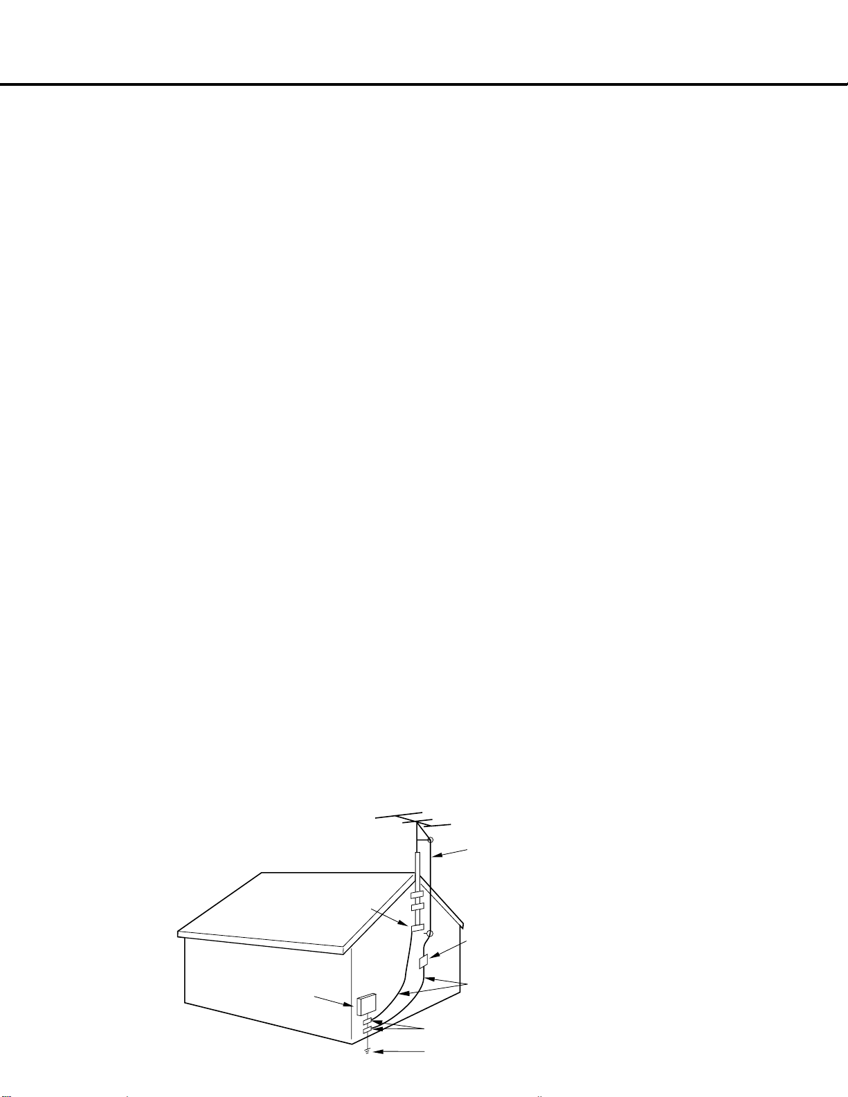
IMPORTANT SAFEGUARDS (CONTINUED)
DAMAGE REQUIRING SERVICE
19.
Unplug this unit from the wall outlet and refer servicing to qualified service personnel under the following conditions:
a.
When the power-supply cord or plug is damaged.
b.
If liquid has been spilled, or objects have fallen into the unit.
c.
If the unit has been exposed to rain or water.
d.
If the unit does not operate normally by following the operating instructions. Adjust only those controls that are covered by
the operating instructions, as an improper adjustment of other controls may result in damage and will often require extensive
work by a qualified technician to restore the unit to its normal operation.
e.
If the unit has been dropped or the cabinet has been damaged.
f.
When the unit exhibits a distinct change in performance, this indicates a need for service.
REPLACEMENT PARTS
20.
When replacement parts are required, be sure the service technician uses replacement parts specified by the manufacturer or
those that have the same characteristics as the original parts.
Unauthorized substitutions may result in fire, electric shock or other hazards.
SAFETY CHECK
21.
Upon completion of any service or repairs to this unit, ask the service technician to perform safety checks to determine that the unit
is in proper operating condition.
WALL OR CEILING MOUNTING
22.
The product should be mounted to a wall or ceiling only as recommended by the manufacturer.
HEAT
23.
The product should be situated away from heat sources such as radiators, heat registers, stoves, or other products (including
amplifiers) that produce heat.
DISC TRAY
24.
Keep your fingers well clear of the disc tray as it is closing. It may cause serious personal injury .
CONNECTING
25.
When you connect the product to other equipment, turn off the power and unplug all of the equipment from the wall outlet. Failure
to do so may cause an electric shock and serious personal injury. Read the owner's manual of the other equipment carefully and
follow the instructions when making any connections.
SOUND VOLUME
26.
Reduce the volume to the minimum level before you turn on the product. Otherwise, sudden high volume sound may cause hearing
or speaker damage.
SOUND DISTORTION
27.
Do not allow the product output distorted sound for a longtime. It may cause speaker overheating and fire.
HEADPHONES
28.
When you use the headphones, keep the volume at a moderate level. If you use the headphones continuously with high volume
sound, it may cause hearing damage.
LEASER BEAM
29.
Do not look into the opening of the disc tray or ventilation opening of the product to see the source of the laser beam. It may cause
sight damage.
DISC
30.
Do not use a cracked, deformed, or repaired disc. These discs are easily broken and may cause serious personal injury and
product malfunction.
NOTE TO CATV SYSTEM INSTALLER
31.
This reminder is provided to call the CATV system installer’s attention to Article 820-40 of the NEC that provides guidelines for
proper grounding and, in particular, specifies that the cable ground shall be connected to the grounding system of the building, as
close to the point of cable entry as practical.
EXAMPLE OF ANTENNA GROUNDING AS PER THE NATIONAL ELECTRICAL CODE
ELECTRIC SERVICE
EQUIPMENT
NEC-NATIONAL ELECTRICAL CODE
S2898A
ANTENNA LEAD IN WIRE
GROUND CLAMP
ANTENNA DISCHARGE UNIT
(NEC SECTION 810-20)
GROUND CLAMPS
GROUND CLAMPS
POWER SERVICE GROUNDING ELECTRODE SYSTEM
(NEC ART 250, PART H)
A1-3
Page 16
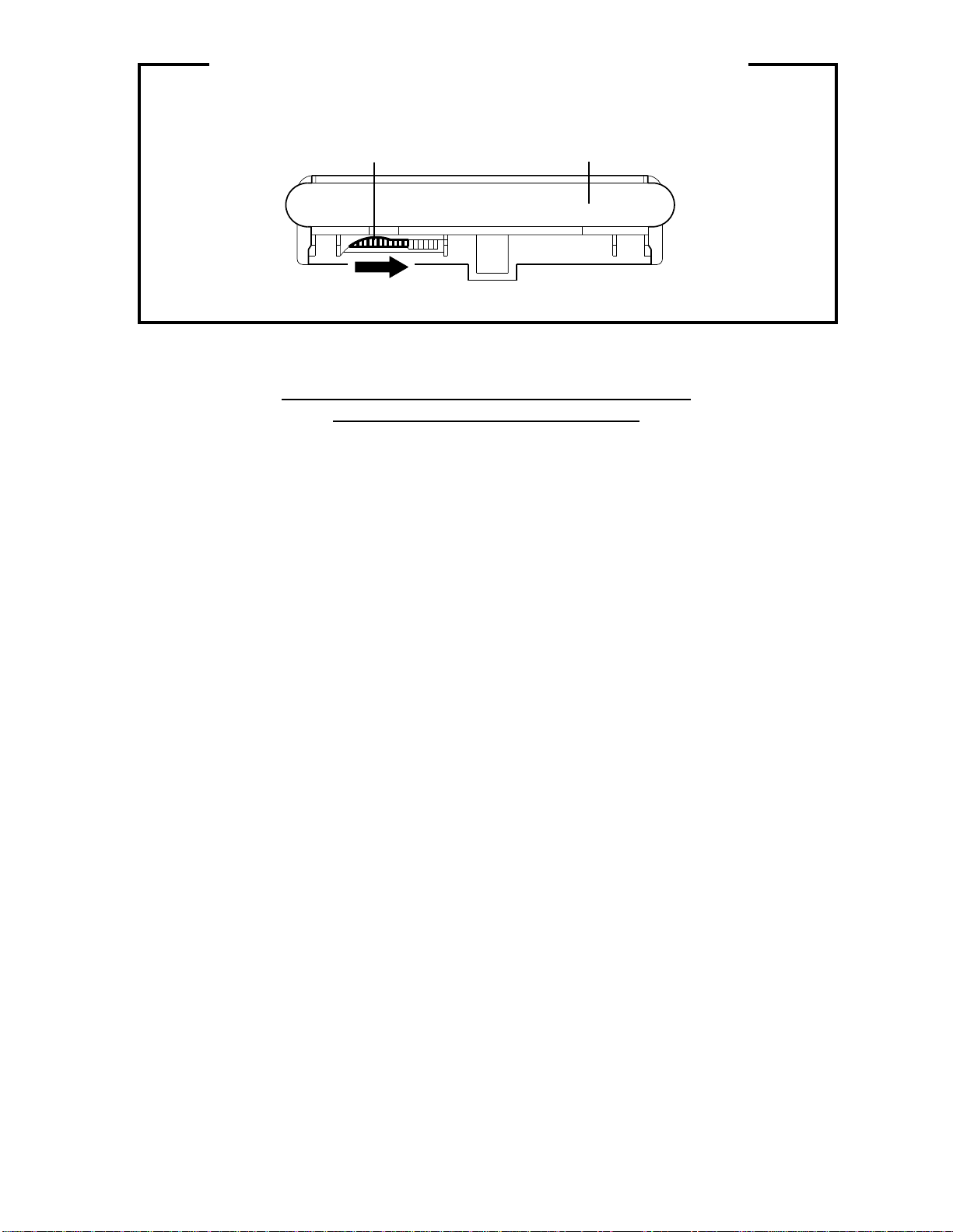
DISC REMOVAL METHOD AT NO POWER SUPPLY
1.2.Remove the Top Cabinet and Front Cabinet. (Refer to item 1 of the DISASSEMBLY INSTRUCTIONS.)
Rotate the black gear of Deck CD section in the direction of the arrow by hand, remove the disc from
Deck CD. (Refer to Fig. 1)
Gear (Black)
Deck CD
Fig. 1
PARENTAL CONTROL - RATING LEVEL
4 DIGIT PASSWORD CANCELLATION
If the stored 4 digit password in the Rating Level menu needs to be cancelled, please follow the steps below.
Turn Unit ON.
1.
Press and hold the 'STOP' key on the front panel.
2.
Simultaneously press and hold the '7' key on the remote control unit.
3.
Hold both keys for more than 3 seconds.
4.
The On Screen Display message 'PASSWORD CLEAR' will appear.
5.
The 4 digit password has now been cleared.
6.
NB: The above procedure will reset ALL of the player's settings to the default factory state.
A1-4
Page 17

• OWNER'S MANUAL
TABLE OF CONTENTS
CAUTION .............................................................................................................................................................
IMPORTANT SAFEGUARDS ..............................................................................................................................
DISC REMOVAL METHOD AT NO POWER SUPPLY........................................................................................
PARENTAL CONTROL- RATING LEVEL ..........................................................................................................
TABLE OF CONTENTS.......................................................................................................................................
GENERAL SPECIFICATIONS ............................................................................................................................
DISASSEMBLY INSTRUCTIONS
1.REMOVAL OF MECHANICAL PARTS AND P.C. BOARDS .........................................................................
2.REMOVAL AND INSTALLATION OF FLAT PACKAGE IC ...........................................................................
SERVICING FIXTURES AND TOOLS ................................................................................................................
RE-WRITE FOR DVD FIRMWARE .....................................................................................................................
TROUBLESHOOTING GUIDE ............................................................................................................................
PRINTED CIRCUIT BOARDS
DVD...................................................................................................................................................................
POWER.............................................................................................................................................................
BLOCK DIAGRAMS
DVD FRONT/BACK END..................................................................................................................................
POWER ............................................................................................................................................................
SCHEMATIC DIAGRAMS
MPEG................................................................................................................................................................
MEMORY ..........................................................................................................................................................
SYSCON ...........................................................................................................................................................
DSP...................................................................................................................................................................
MOTOR DRIVE.................................................................................................................................................
READ CHANNEL ..............................................................................................................................................
AUDIO...............................................................................................................................................................
DISPLAY ...........................................................................................................................................................
POWER.............................................................................................................................................................
INTERCONNECTION DIAGRAM .....................................................................................................................
WAVEFORMS ......................................................................................................................................................
MECHANICAL EXPLODED VIEW .......................................................................................................................
PACKING DIAGRAM ...........................................................................................................................................
MECHANICAL REPLACEMENT PARTS LIST ...................................................................................................
ELECTRICAL REPLACEMENT PARTS LIST .....................................................................................................
A1-1
A1-2~A1-3
A1-4
A1-4
A2-1
A3-1~A3-5
B1-1
B2-1, B2-2
C-1
C-1
D-1~D-8
E-1, E-2
E-3, E-4
F-1, F-2
F-3, F-4
G-1, G-2
G-3, G-4
G-5, G-6
G-7, G-8
G-9, G-10
G-11, G-12
G-13, G-14
G-15, G-16
G-17, G-18
G-19, G-20
H-1, H-2
I1-1
I2-1
J1-1
J2-1~J2-3
A2-1
Page 18

GENERAL SPECIFICATIONS
(
G-1 Outline of the product DVD VIDEO PLAYER
G-2 DVD System Color System NTSC
Disc
Disc Diameter 120 mm , 80 mm
Deck Disc Loading System Front Disc Loading
Motor 3 Motors
Pick up 1-Lens 2-Beams System
Playback time (Max) DVD 1-Layer 135min (4.7GB)
DVD 2-Layer 245min (8.5GB)
CD 74min
VIDEO CD 74min
Search speed Fwd 2-20 times / 4 step
Actual 2-45 times (DVD, Video CD)
Actual 2-45 times (DVD, Video CD)
Slow speed Fwd 1/7 -1/2 times
Actual --
Actual --
G-3 Power Power Source AC 120V 60Hz
DC Power Consumption 10 W
Stand by 4 W
Per Year -- W
Protector Power Fuse Yes
G-4 Signal Video Signal Output Level 1 V p-p/75 ohm
S/N Ratio (Weighted) 65 dB
Horizontal Resolution at DVD 500 Lines
RGB Signal Output Level --- V p-p/75 ohm
Component Video Output Level(Y) 1.0 V p-p/75 ohm
Output Level(Cb,Cr) 0.7 V p-p/75 ohm
Audio Signal Input Level Microphone --- dBm/ --- ohm
Output Level Line -6 dB/ 1k ohm (0dB=0.775Vrms)
S/N Ratio at (Weighted) 90dB
Harmonic Distortion : 0.008% (1KHz)
Frequency Response : at DVD 4 Hz - 22 KHz
at VIDEO CD 4 Hz - 20 KHz
at CD 4 Hz - 20 KHz
Digital Audio Signal Output Level 0.5 V p-p/75 ohm
DVD Video,CD-DA, CD-R(MP3, CD-DA),
Rev 2-20 times / 4 step
Rev 1/7 -1/2 times
MP3, CD-DA), Video CD
CD-RW
4-40 times (CD)
4-40 times (CD)
A3-1
Page 19

GENERAL SPECIFICATIONS
G-5 Interface Switch Front Power Yes
Rear Attenuator No
Volume Phones Volume No
Indicator LED Power Yes (Green)
Fluorescent Indicator
Terminals Front No
Rear Video Output RCA x 1
G-6 Set Size Approx. W x D x H (mm) 430 x 206.5 x 59
G-7 Weight Net (Approx.) 2.0kg( 4.4 lbs)
G-8 Regulation Safety UL/CSA
G-9 Temperature Operation 5oC - 40oC
G-10 Operating Humidity Less then 80% RH
Play Yes
Open/Close Yes
Skip(>>) Yes
Skip(<<) Yes
Still/Pause No
Stop Yes
Shuttle(Search/REV/FWD) No
Main Power SW No
Video/RGB Selector No
S-Video/Component Selector Yes
Mic Volume No
Echo Volume No
Rec/OTR No
Stand By No
Rec/Pause No
Repeat No
Disc No
Play No
Still No
Surround No
Level Meter No
DVD Yes
Pause Yes
Track Yes
A Yes
-B Yes
VIDEO No
CD Yes
Play Yes
ALL Yes
PROG No
Mic Mark No
Title No
Repeat Yes
PBC No
Angle No
Chapter No
Music Calender(1-14,Play) No
7-seg Digit(6) Yes
S-Video Output S-Jack x 1
Component Video Output RCA x 3(Y,Cr,cb)
D1 No
Audio Output RCA x 2(Stereo)
Euro Scart No
Digital Audio Output Coaxial,Optical
Dolby 5.1CH Auidio Output No
AC Inlet No
Slide SW(S-Video/Component) Yes
Gross (Approx.) 3.0kg( 6.6 lbs)
Radiation FCC/IC
Laser DHHS
Storage -20oC - 60oC
A3-2
Page 20

GENERAL SPECIFICATIONS
G-11 On Screen Menu Yes
Display Menu Type Character
Open Yes
Close Yes
No disc Yes
Reading Yes
Play Yes
Still/Pause Yes
Stop Yes
Prohibit Mark Yes
Step Yes
Next Yes
Back Yes
Random Yes (CD, MP3, Video CD)
Repeat Yes
Slow+ ## Yes
Slow- ## Yes
Search+ ## Yes
Search- ## Yes
Jump Yes
Resume Yes
Title No. Yes
Chapter No. Yes
Track No. Yes
Time Yes
Sub Title No. Yes
Angle No. Yes
Vocal On/Off Yes
Audio No. Yes
Audio Stereo L/R Yes (Video CD)
Zoom Yes
Marker No. Yes
Program Play Back Yes (CD, MP3, Video CD)
Spatializer On/Off Yes
MP3 Folder Name Yes
G-12 OSD Language Eng Fre Spa
Language
Menu Yes
SubTitle Yes
Audio Yes
Picture
TV Screen Size Yes
OSD Display On/Off Yes
Sound
DRC Yes
dts Decode No
Output(5.1ch/ 2ch) No
Surround On/Off No
Center On/Off No
Sub Woofer On/Off No
Parental
Password Lock/ Un Lock Yes
Rating Level Yes
Other
OSD Language(Set up Language) Yes
Output(RGB/Composite) No
File Name Yes
File No Yes
Time Yes
Track No Yes
A3-3
Page 21

GENERAL SPECIFICATIONS
G-13 Remote Unit RC-FS
Control Glow in Dark Remocon No
G-14 Features Auto Power Off No
Format NEC
Custom Code 45-BA h
Power Source Voltage(D.C) 3V
UM size x pcs UM-4 x 2 pcs
Total Keys 40 Key
Keys Power Yes
DISPLAY Yes
OPEN/CLOSE Yes
1 Yes
2 Yes
3 Yes
4 Yes
5 Yes
6 Yes
7 Yes
8 Yes
9 Yes
0 Yes
CLEAR Yes
PLAY Yes
STOP Yes
PAUSE/STILL/STEP Yes
|<<(SKIP) Yes
>>|(SKIP) Yes
<<(SEARCH) Yes
>>(SEARCH) Yes
SLOW - Yes
SLOW + Yes
MENU Yes
TITLE (TOP MENU) Yes
SET UP Yes
RETURN Yes
SELECT/ENTER Yes
UP Yes
DOWN Yes
RIGHT Yes
LEFT Yes
AUDIO Yes
ANGLE Yes
SUB TITLE Yes
ON/OFF(SUB TITLE) No
PLAY MODE Yes
ZOOM Yes
MARKER Yes
REPEAT(A-B) Yes
REPEAT(MODE) No
SEARCH MODE(JUMP) Yes
Mic On/Off No
Parental Lock Yes
Progressive Video Out No
Echo No
Mic Mixing No
Digital Out (Dolby Digital) Yes
(MPEG) Yes
(PCM) Yes
(DTS) Yes
Down Mix Out (Dolby Digital) Yes
(DTS) No
Satializer (N-2-2) Yes
Screen Saver No
Dynamic Range Control Yes
Video CD Playback Yes
MP3 Playback Yes
A3-4
Page 22

GENERAL SPECIFICATIONS
C
Surfaces
G-15 Accessories Owner's Manual Language English
Remote Control Unit Yes
Guarantee Card No
Warning Sheet No
Service Station List No
Important Tag No
AC Plug Adapter No
Quick Set-up Sheet Yes (Spanish)
Battery Yes
AC Cord No
AV Cord Yes (1.2m)
S-Video Cable No
21pin cable No
800 No Sticker No
Toll Free Insert Sheet No
Safety Tip No
Security Tag No
Information Sheet No
G-16 Carton Master Carton No
Gift Box Yes
Drop Test
Container Stuffing 3,175 Sets/40' container
G-17 Cabinet Material Cabinet Front PS 94V2/DECABROM
w/Guarantee Card Yes
Buyer Model No SD-1810
UM size x pcs UM-4 x 2 pcs
OEM Brand No
Content --- Sets
Material --- / ---
Dimensions W x D x H(mm) ---
Description of Origin ---
Material Single Full Color Carton
W/Color Phote Label No
Dimensions W x D x H(mm) 502 x 290 x 138
Design As Per BUYER 's
Description of Origin Yes
Natural Dropping At 1
Height (cm) 80
orner / 3 Edges / 6
A3-5
Page 23
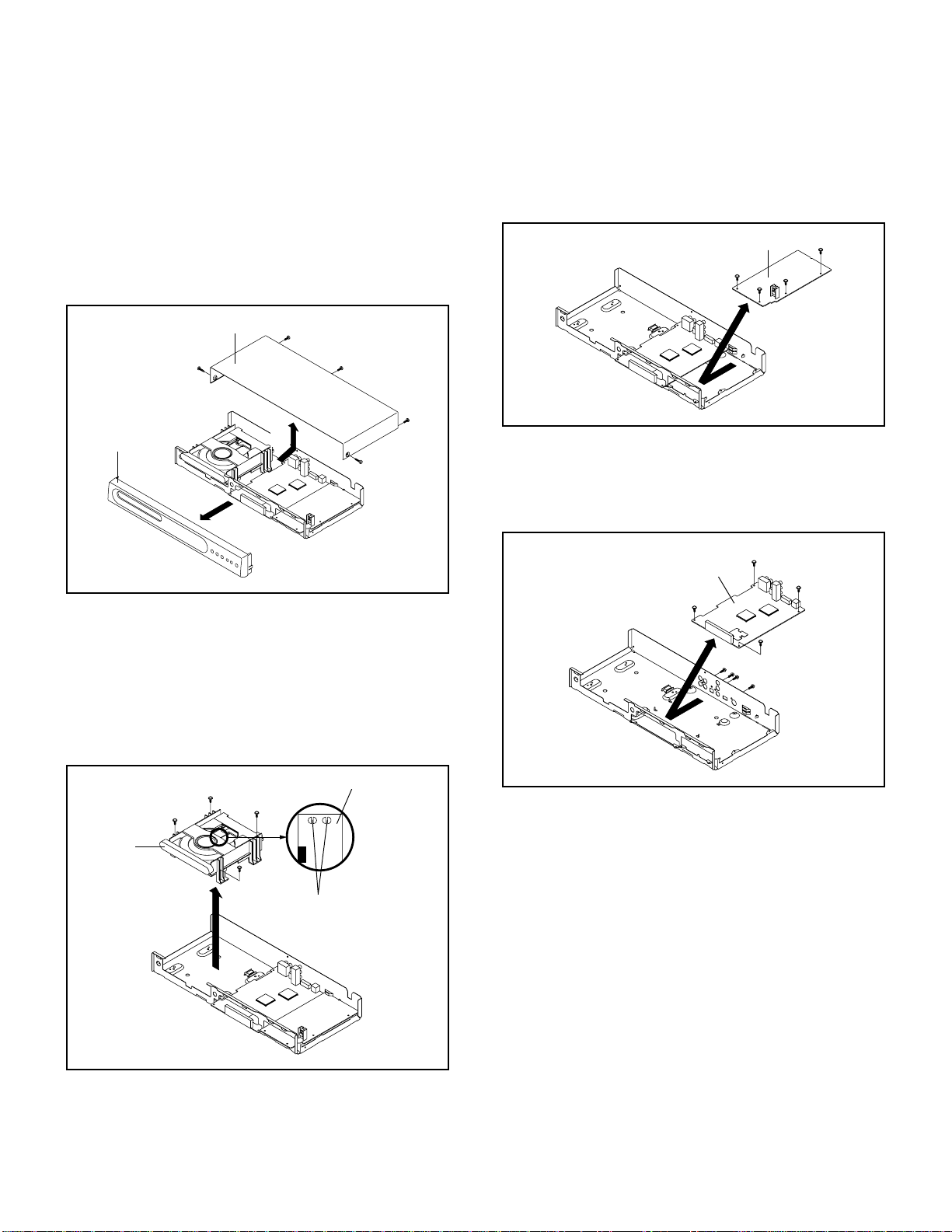
DISASSEMBLY INSTRUCTIONS
1.
REMOVAL OF MECHANICAL PARTS
AND P.C. BOARDS
1-1:
TOP CABINET AND FRONT CABINET
(Refer to Fig. 1-1)
1.
Remove the 5 screws 1.
2.
Remove the Top Cabinet in the direction of arrow (A).
3.
Unlock the 4 supports 2.
4.
Remove the Front Cabinet in the direction of arrow (B).
Top Cabinet
1
Front Cabinet
2
(B)
2
2
1
1
(A)
1
2
1
Fig. 1-1
1-3: POWER PCB (Refer to Fig. 1-3)
1.
Disconnect the following connectors: (CP1002, CP1003).
2.
Remove the 4 screws 1.
3.
Remove the Power PCB in the direction of arrow.
Power PCB
1
1
1
1
1-4: DVD PCB (Refer to Fig. 1-4)
1.
Remove the 4 screws 1.
2.
Remove the 4 screws 2.
3.
Remove the DVD PCB in the direction of arrow.
2
DVD PCB
2
2
Fig. 1-3
1-2: DECK CD (Refer to Fig. 1-2)
1.
Make the short circuit on the position as shown Fig. 1-2
using a soldering. If you remove the Deck CD with no
soldering, the Laser may be damaged.
2.
Disconnect the following connectors:
(CP2301, CP2302, CP2601).
3.
Remove the 4 screws 1.
4.
Remove the Deck CD in the direction of arrow.
Pick Up PCB
Make the sort circuit
using a soldering.
Deck CD
1
1
1
1
Fig. 1-2
2
1
1
1
1
Fig. 1-4
B1-1
Page 24

DISASSEMBLY INSTRUCTIONS
2. REMOVAL AND INSTALLATION OF FLAT
PACKAGE IC
REMOVAL
1. Put the Masking Tape (cotton tape) around the Flat
Package IC to protect other parts from any damage.
(Refer to Fig. 2-1.)
NOTE
Masking is carried out on all the parts located within
10 mm distance from IC leads.
Masking Tape
(Cotton Tape)
2. Heat the IC leads using a blower type IC desoldering
machine. (Refer to Fig. 2-2.)
NOTE
Do not add the rotating and the back and forth directions force on the IC, until IC can move back and forth
easily after desoldering the IC leads completely.
IC
Fig. 2-1
Blower type IC
desoldering machine
3. When IC starts moving back and forth easily after
desoldering completely, pickup the corner of the IC using
a tweezers and remove the IC by moving with the IC
desoldering machine. (Refer to Fig. 2-3.)
NOTE
Some ICs on the PCB are affixed with glue, so be
careful not to break or damage the foil of each IC
leads or solder lands under the IC when removing it.
Blower type IC
desoldering machine
Tweezers
IC
4.5.Peel off the Masking Tape.
Absorb the solder left on the pattern using the Braided
Shield Wire. (Refer to Fig. 2-4.)
NOTE
Do not move the Braided Shield Wire in the vertical
direction towards the IC pattern.
Fig. 2-3
Braided Shield Wire
Soldering Iron
IC
Fig. 2-2
IC pattern
Fig. 2-4
B2-1
Page 25
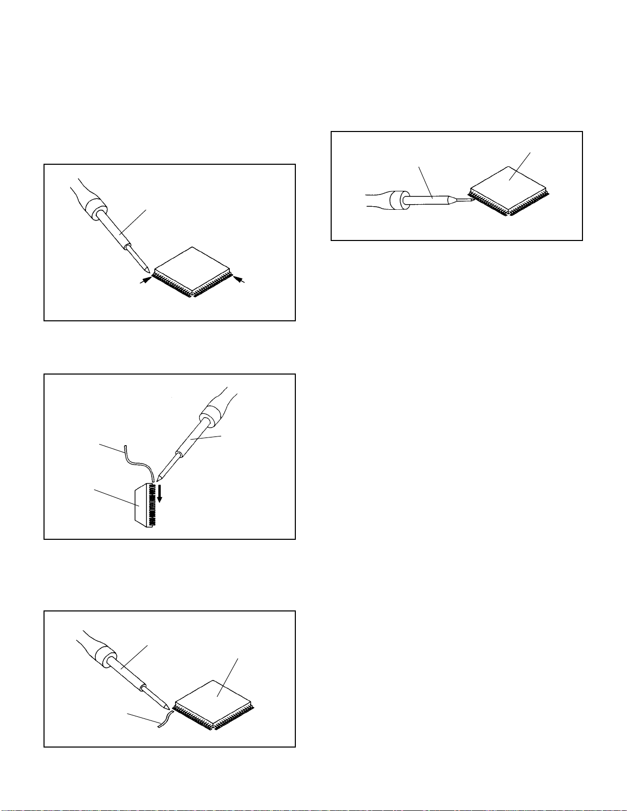
DISASSEMBLY INSTRUCTIONS
INSTALLATION
1. Take care of the polarity of new IC and then install the
new IC fitting on the printed circuit pattern. Then solder
each lead on the diagonal positions of IC temporarily.
(Refer to Fig. 2-5.)
Soldering Iron
Solder temporarily
Solder temporarily
Fig. 2-5
2. Supply the solder from the upper position of IC leads
sliding to the lower position of the IC leads.
(Refer to Fig. 2-6.)
4. When bridge-soldering between terminals and/or the
soldering amount are not enough, resolder using a Thintip Soldering Iron. (Refer to Fig. 2-8.)
IC
Thin-tip Soldering Iron
Fig. 2-8
5. Finally, confirm the soldering status on four sides of the
IC using a magnifying glass.
Confirm that no abnormality is found on the soldering
position and installation position of the parts around the
IC. If some abnormality is found, correct by resoldering.
NOTE
When the IC leads are bent during soldering and/or
repairing, do not repair the bending of leads. If the
bending of leads are repaired, the pattern may be
damaged. So, be always sure to replace the IC in this
case.
Solder
IC
Supply soldering
from upper position
to lower position
Soldering Iron
Fig. 2-6
3. Absorb the solder left on the lead using the Braided
Shield Wire. (Refer to Fig. 2-7.)
NOTE
Do not absorb the solder to excess.
Soldering Iron
IC
Braided Shield Wire
Fig. 2-7
B2-2
Page 26
SERVICING FIXTURES AND TOOLS
JG155B Remote control JIG
Ref. No.
JG155B
JG176
Part No.
APJG155B00
APJG176011
JG176 Up-Date Disc
Parts Name
Remote control JIG
Up-Date Disc
Check for the Firmware version
Up-Date of the Firmware
Up-Date of the Firmware
RE-WRITE FOR DVD FIRMWARE
Turn on the power, and open the tray.
1.
Place the Up-Date Disc and close the tray. (Refer to SERVICING FIXTURE AND TOOLS)
2.
The reading will start and the Fig. 1 screen will appear.
Firmware upgrade
Cancel Start
Remarks
Fig. 1
Select the "Start" with right ( ) key of the normal remote control, then press the ENTER key.
3.
The data reading will start.
At this time, the horizontal noise lines may appear. But no problem.
After the finishing of the data reading, the tray will open automatically and power it off.
Remove the Up-Date Disc.
4.
After the write, set to the initializing of shipping.
5.
Turn on the power, then press the "FACTORY INITIALIZE" key on the remote control JIG (JG155B) for more than 1 second.
Press the channel (5) key on the normal remote control. If the "Complete" appears on the TV monitor, power it off.
6.
CHECK FOR THE FIRMWARE VERSION
7.
Turn on the power, then press "CHECK SUM" key on the remote control JIG (JG155B) for more than 1 second.
Firmware version will be displayed on the top left of the screen.
No Disc
ZCA25070
Fig. 2
When the changed version displays, the Re-write will be completed.
Turn off the power
8.
∆
Z C A 2 5 0 7 0
Fixed
Release date (Example: 2002.5.7)
Released times on the same date
A = October
B = November
C = December
C-1
Page 27
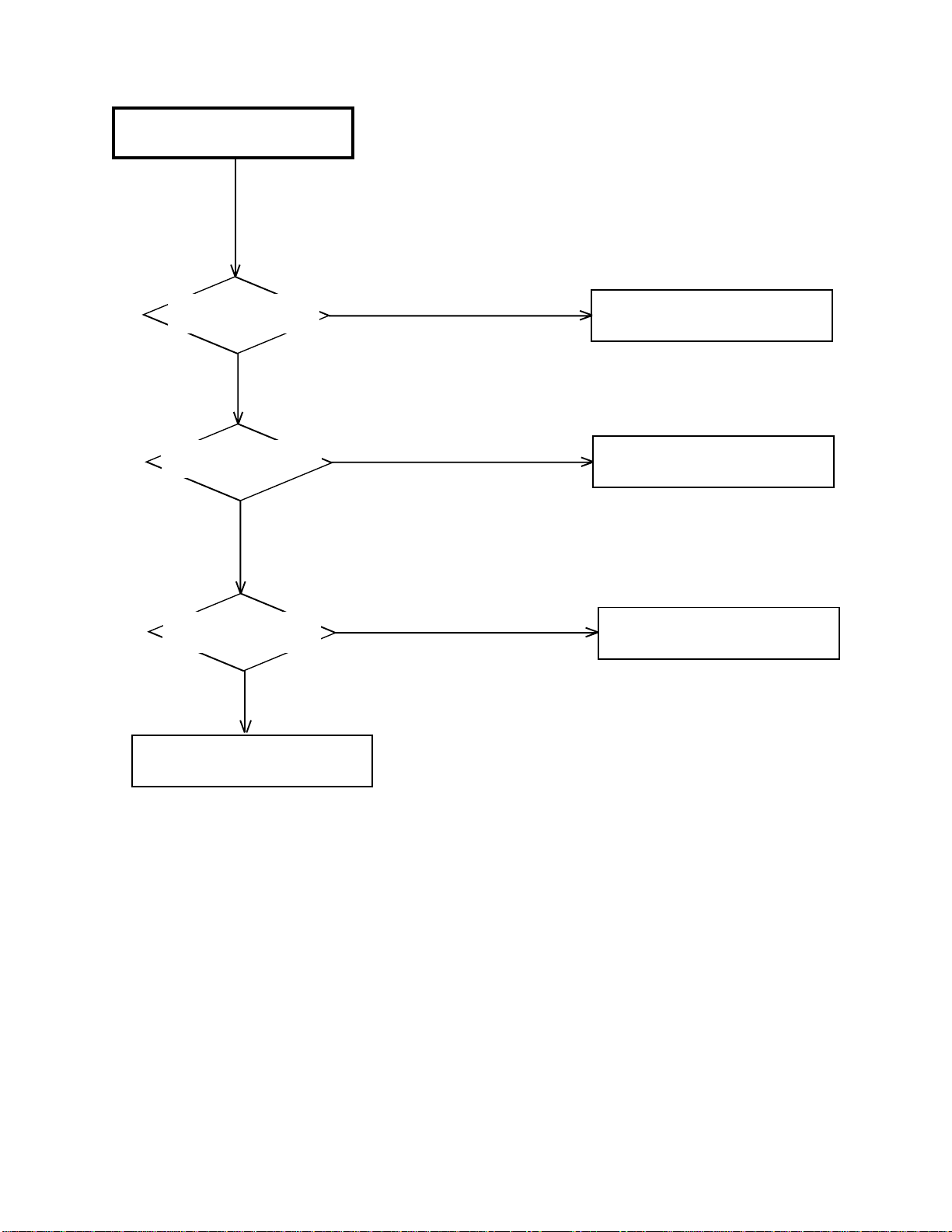
POWER DOES NOT TURN ON
TROUBLESHOOTING GUIDE
Is the voltage at pin 11
of CP502 about 3.3V ?
Yes
Is the voltage at pin 10
of CP502 about 5V ?
Yes
Is there waveform at
X1001 about 3.0Vp-p ?
Yes
No
No
No
Check Q510 and peripheral circuit.
Check IC502 and peripheral circuit.
Check X1001, IC1001
and peripheral circuit.
Write DVD ROM DATA.
D-1
Page 28

DECK DOES NOT ACCEPT
OPEN/CLOSE
TROUBLESHOOTING GUIDE
Is the voltage at pin 3 and
14 of IC2301 about DC9V ?
Yes
Is the lose connection
at CD2301 &CD2302 to
DECK ?
No
When AC IN,
DECK MOTOR turn ?
No
Check IC1001 and
peripheral circuit.
No
Yes
Yes
Check P.CON 9V line of
POWER BLOCK.
Check CD2301&CD2302
connection to DECK.
Check OPEN or SHORT
at Pin 64,68,73 and 74 of
IC1001.
D-2
Page 29

TROUBLESHOOTING GUIDE
DOES NOT LIGHT ON DISPLAY
Is the voltage at pins 1 and
2 of V651 about -13V ?
Yes
Is the voltage at pins 31 and
32 of V651 about -15V ?
Yes
Is the voltage at pin 18
of IC651 about 5V ?
Yes
Is the voltage at pin 10
of IC651 about -20V ?
No
No
No
No
Check FILAMENT(+)
line of POWER BLOCK.
Check FILAMENT(-)
line of POWER BLOCK.
Check AT+D5V line of
POWER BLOCK.
Check -20V line of
POWER BLOCK.
Yes
Replace V651 or IC651.
D-3
Page 30

TROUBLESHOOTING GUIDE
NO PLAYBACK PICTURE OF AV
JACK .
Is there VIDEO signal
at pin 103 of IC4001 ?
No
Is the voltage at pin 116
or 142 of IC4001 at 9V ?
Yes
Is the waveform at pins
153-159 of IC4001 ?
No
Change IC4001.
Yes
No
Yes
Check J7001 and peripheral
circuit.
Check IC4006 and peripheral
circuit.
Check IC2001 and peripheral
circuit.
D-4
Page 31
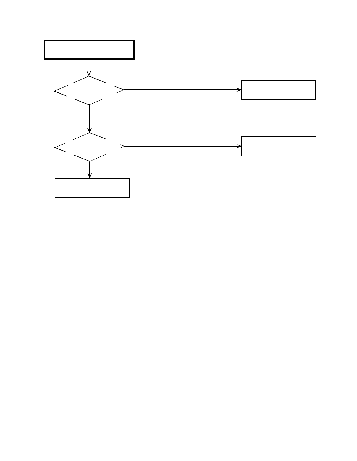
NO PLAYBACK PICTURE OF
S-VIDEO JACK
TROUBLESHOOTING GUIDE
Is there Y signal at
pin 105 of IC4001 ?
No
Is there VIDEO signal
at pin 103 of IC4001 ?
Yes
Change IC4001.
Yes
No
Check J8001 and peripheral
circuit.
REFER TO "NO PLAYBACK
PICTURE OF AV JACK ".
D-5
Page 32

TROUBLESHOOTING GUIDE
NO COLOR PLAYBACK PICTURE
OF S-VIDEO JACK
Is there C signal at
pin 106 of IC4001 ?
No
Is there Y signal at
pin 105 of IC4001?
No
Is there VIDEO signal
at pin 103 of IC4001?
No
Is the voltage at pin 4,
89 and 104 of IC4001
about 5.0V?
Yes
No
Yes
No
Check J8001 and peripheral
circuit.
REFER TO "NO PLAYBACK
PICTURE OF S-VIDEO JACK".
REFER TO "NO PLAYBACK
PICTURE OF AV JACK" .
Check AT+3V line on
POWER BLOCK.
Yes
Change IC4001.
D-6
Page 33
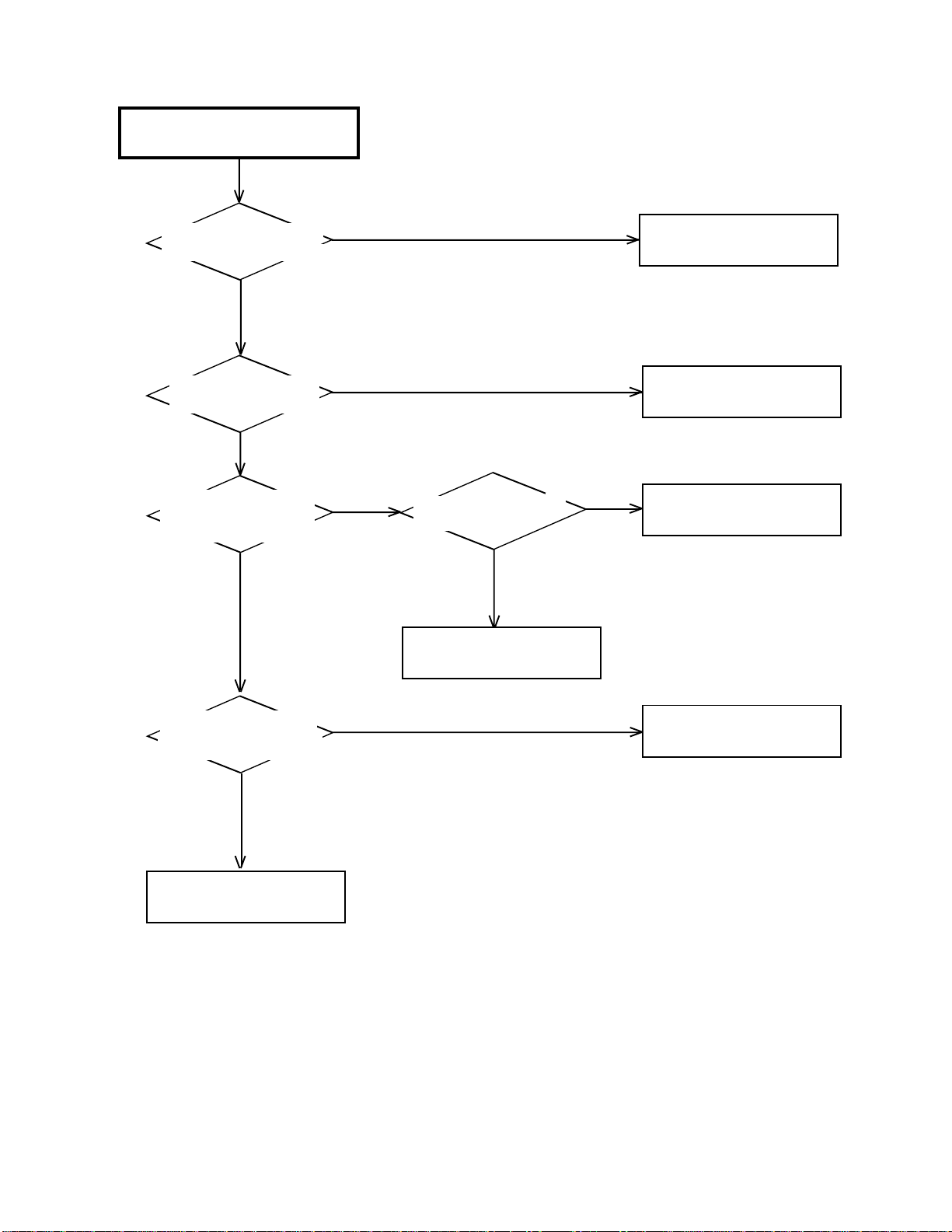
TROUBLESHOOTING GUIDE
NO DIGITAL AUDIO ON
PLAYBACK OF COAXIAL JACK
Is there waveform at pin
6 of J7001 about 5Vp-p ?
No
Is the voltage at 16 pin
of IC8504 about 3.3V ?
No
When DVD Playback,
Is there waveform at pin
1 of IC8504 ?
No
Yes
No
Yes
Pin 9 and 10 of IC8504
is LOW ?
No
Check IC1001 and peripheral
circuit.
Check connection at RCA
Cable.
Check AT+3.3V line on
POWER BLOCK.
Yes
Change IC8504.
When CD Playback,
Is there waveform at pin
4 of IC8504 ?
No
Check IC2001 and peripheral
circuit.
Yes
Check IC4001 and peripheral
circuit.
D-7
Page 34

NO ANALOG AUDIO ON
PLAYBACK
TROUBLESHOOTING GUIDE
Is there AUDIO signal at
pin 7 and 8 of IC8503 ?
No
Is there waveform at
pin 2 of IC8503?
No
When DVD Playback , Is
there VIDEO OUTPUT ?
Yes
Change IC4001.
Yes
Yes
No
Check IC7004 and peripheral
circuit.
Check IC8503 and peripheral
circuit.
Check IC2001 and peripheral
circuit.
D-8
Page 35

PRINTED CIRCUIT BOARDS
DVD (TOP SIDE)
W829 W803
D7017
D7016
C4047
C4019
C4020
IC1002
1
76
C1015
R1021 R1051
R1071
R1072
C1012
R1005
B4003
R1004
C4045
R2308
R1056
D1003
D1002
J8001
C651
L7005L7007
W836
IC4002
C4023
R1027
R1017
R1040
R1049
R1059R1057
R1026
R1023
R1053
R1024
R1038
R1066
R1037
R1035
R1012
R1011
R1036
R1032
R1009
R1010
X1001
R1014
R1030
R1002
R1001
C1007
B1001
R1034
R1020
R1016
R1015
CP1003
IC1006
C1001
R2315
Q1002Q1001
R2316
Q1004
Q1003
D1005 R1060
C2301
B2606
C2653
C2013
C7064
R678
C2659
R2670
C2608
Q2616
R2617
R2672
Q2613
R2669
C2614
Q2612
C1018
R4028
C2002
C7056
R4027
C4038
B4004
B8502
R7050
R7060R7047
C7053
C7052
J7001
B7001
C7065
C7035
R7054R7055
Q7009
Q7010
R7053C7036R7029
R7023
L7011
C7016
CP1002
Q2303
Q2302
R2307
B2601
CP2601
CP2301
C2306
CP2302
C2304
C2305 C2308
B2003
R2324
R2609 R2608
C2303
R2302
R2321
R7049
R7071
C7055
B2002
R4029
Q2301
R2306
R2304
R2323
C2307
Q2304
R2309
R2303 R2305
R2311
B7011
D7009
D7008
Q7006
Q7005
C4044
L1001
Q2603
C2609
D2601
D2602
Q2604
C2610
R2322
R2312
OS651
W813
R7048
R7072
R7052
R7051
C7057
C7004
C4041
R2671
R2610
R2611
C2658
R2301
C674
W816
R7041
C7054
C7070
Q7003
Q7004
C7069
R7039
B8501
D7011
C8537
C4043
IC4006
C8534
C2050
C2046
C2024
C2023
C2611
IC2002
C2041
C2048
C2033
C2612
C2045
B2604
Q2615
R2674
R2673 R2675
C2654
Q2614
C2615
R2620
R2667
R2623
Q2605
C2602
R2621
C2616
R2643
R2650
R2642
R2631
R2607
R2606
C2620
R651
D657
OS7001
J7003
C7063
L7003
C7024
D7003
D7004
C7026
R7057
C7042
R7028
C7039
R7038
R7035
C7038 R7040
C7041
IC7004
C7040
R7036
R7022R7017
C8536
C7068
R7014
C8503
IC8503
R8520
IC8504
C8535
R2045
R2044
C2035
R2042
R2043
C2053
R2036
R2035
R7021
Q7002
C7071
R7011
R7058R7059
R7010
C7032
R7056
R7030
C7044
C7067
R7004
C8506
C8538
B4001
C2036
C2034
C2043
C4022
C4037
C4021
C4039
C4026
W837
W861
R4018
C4025
R4016
R4019
R4015
R4017
C4034
R4011
R4010
C4017
C2038R2052B2001
R2037
157
IC2001
R2024
R2023
R2022
R2021
C2051
R2020
1
R2604R2605
Q2606Q2601
B2602
C2605
C2613
R2634
R2628
R2638
C2619
R2627
1
IC2602
21
C2618
R2629
Q653
C2010
C2652
R2640
R2644
C2627
C2634
R2630
R2632
W814
D658
C2018
C2648
C2017
R2652
R2657
C2637
C2641
61
41
R2639
C2631
R2615
C2656
C2621
R2626
R2622
C2633
C663
C672
W815
R2651
C2655
C2651
C2635
C2636
R2647
R2649
C2646
C2649
R2625
R2614
R2654
C2639
R2666
IC2601
C2640
R2660
IC651
C7007
Q7007
C4042
L7002
R4007
C7003
X4001
C4024
R4008
121
1
R4003
R4002
R4001
C4002
R4004
R4023
X2001
105
53
R2012
C2016
R2011
C2015
R2010
R2009
C2014
R2008
C2011
R2007
C2006
R2006
C2003
R2663
R2665
Q2608
R2653
R2656
R2655
R2659
C2642
R2319
R2317
C2622
R2320
R2310
Q2610
C2647
C2645
Q2607
R2661
R2658
R653
R661
R662
D654
D655
D656
D652
D651
SW7001
C7023
D7010
C7006
D7007
L7001
C7005
R7002
C7001
C4029
C4028
IC4001
C4004
C4005
C4003
R4024
R4026
R4025
C2037
R2033
C2032
R2031
R2030
R2029
R2028
W810
R2027
R2026
R2025
R2064
C2021
R2017
R2016
R2014
R2013
R2668
Q2611
C2643
R2664
Q2609
C2309
R652
C656
Q652
CP661
V651
C7025
C7022
D7015
D7002
D7001
C7002
R7001
C4030
C4027
C7015
C7011
L7004
L7006
D7014
C7014
C7009
R7007
C7012
R7006
C7008
C4032
R4005
C4008
4181
B4002
C4007
C4006
C1004
W807
R1070
R1018
R1068
R1054
R1055
R1067
R1069
C1020
26
IC1001
C1009
51
R1073
R1050
R1046
R1047
R2313 R2318
C2310
R658
R659
R1048
R1039
R1074
IC4005
IC2301
HS2301
C664
C1021
DVD (BOTTOM SIDE)
C661
R665
W804
C2629
R2645
R2633
C2625
R2618
C2650
C2626
C2623
R2603
R2619
C2052
C2049
W851
R7026
C7062
R666
C2617
R2646
R2662
C2644
B2605
R2002
R2001
C2019
R2038
R2039
C2031
R2054
C4035
C4036
R4020
C4012
R7016
C7066
D7018
D7019
C7017
C7010
C7013
R664
R2314
C2315
C4040
R4030
C2009
C2020
C2030
C2040
R2046
R2041
C2039
C4001
R4012
W817
R4006
W806
R4021
C4031
C4013
W828
R1041
B1002
C4009
C4010
C4011
C4014
C4015
C4016
R4009
C4033
W850
R7012
C1016
C1017
W802
R1008
W808
C1013
C1003
R1003
C1002
C1014
C1008
C1006
C1024
C1023
C1022
C4018
C7028C7027
E-1
E-2
Page 36
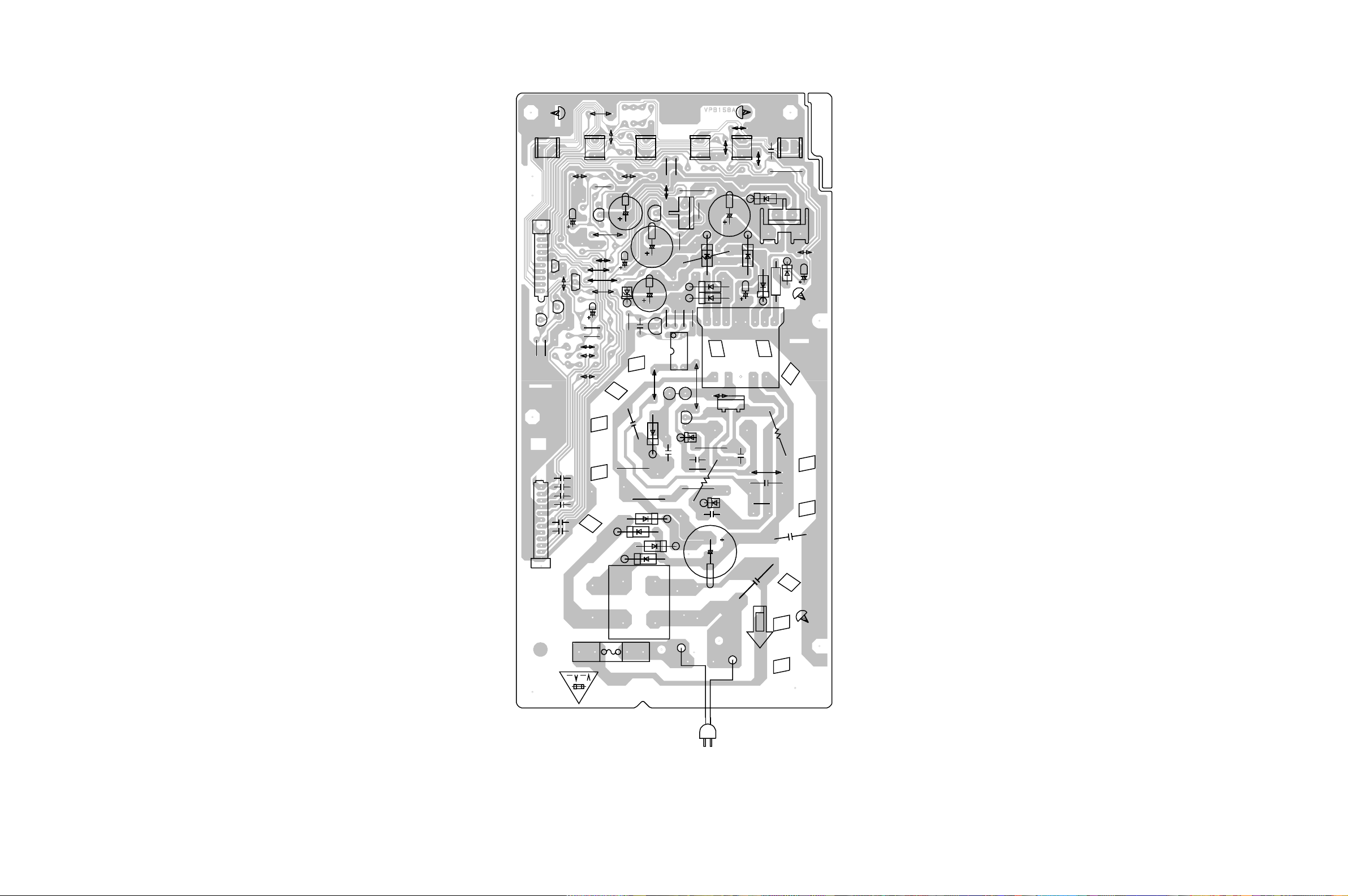
CP503
Q507
R528
CD502
PRINTED CIRCUIT BOARDS
POWER
SOLDER SIDE
W001
W003
W004
W005
W006
R533
Q513
D506
R529
W808
C531
C528
C526
D505
W825
W809
D528
R518
C515
R512_1
D502
C540
D503
C522
IC501
R505
Q508
D509_1
SW665
W012
R517
W803
C513
R523_1
R522_1
IC503
C523
R514
R516
B501
Q502
D504
R506
SW664
R526
R524
R515
IC504
W010
C508
R507
C521
R509
D512
R531
D527
W009
R508
R504
D526
C509
R534
W007
C541
C542
C545
C543
SW661
W813
Q505
Q510
Q512
C544
C546
SW662
C535
R532
W819
W811
W008
W013
W824
SW663
D514_1
T501
Q501_2
C505
R510
C511_1
D507
D510
C518
W011
W822
C514
C529
D511
R
5
0
SW651
R539
HS502
IC502
W002
D516
C527
ICP502
2
C516
C502_1
L501
FH502_1
F501
FH501_1
S501_1
- REPLACE AS MARKED.
RISK OF FIRE
CD501_4
S502_1
E-3 E-4
Page 37

DVD FRONT/BACK END BLOCK DIAGRAM
MECHA
Pickup
Loading
Motor
Spindle
Motor
CD/DVD
A, B, C, D, E, F
T+/–
F+/–
RF AMP
IC2602
LA9702WL
LD_DVD
LD_CD
OPEN/CLOSE
MLD1
MLD2
Motor Driver
IC2301
LA6560
SLD1/2
SP1+/–
SP_FG
D
RFN/P
TE/FE
TOST/ FOST/ BOOT3 T/T
BAL/ F BAL/ETC
SPD/SLD/TD/FD/
SPD_FG
E
A
E
FRONT
X2001
16.9344MHz
RESET
IC1002
PST3229NR
EEPROM
IC1006
S-24C04BFJ
DRAM
IC2002
4M EDO
MD/MA_DATA
DSP
IC2001
LC78661W
WR, RD,
RDY,
DVD RST
X1001
12.5MHz
SDA
SCL
uCom
IC1001
ZR36705
C
C, H, D
DVD/
CD
DATA
H
MA/MD_
DATA
HA/HD_DATA
E, B
REMIN
SDRAM
IC4002
16M
MA/MD_
DATA
MPEG Decoder
W/Video Encoder
IC4001
ZR36732(Vaddis 4)
SPDIF/CD
ROM
(SST)
IC4005
8M FLASH
BACK
1.9V REG
IC4006
PQ070XZ01ZP
H
ASDATAO
ABCLK
AMCLK
ALRCLK
HA/HD_DATA
H
C
X4001
27MHz
SPDIF/DVD
AUDIO DAC
IC8503
PCM 1748E
AUDIO_SW
IC8504
SN74LV4052
VIDEO OUT
AUDIO OUT
B, F
DIGITAL OUT
F
J7003
Y.U.V
J8001
S.TERMINAL
J7001
CVBS
L/R
D_OUT
OS7001
OPT TRANSFORMER
F-1
B, G
FP_SEL/DIH
FP_CLK/D_OUT
FIP DRIVER
IC651
BU2977FS
G/P_DATA
FIP
V651
HNV-06SS71
OS651
PIC-37143SY
A P.CON+9V
B AT+D5V
C P.CON+D5V
D P.CON+A5V
E AT+D3.3V_M
F AT+3.3V
G -20V
H P.CON+D3.3VA (AT)
F-2
Page 38
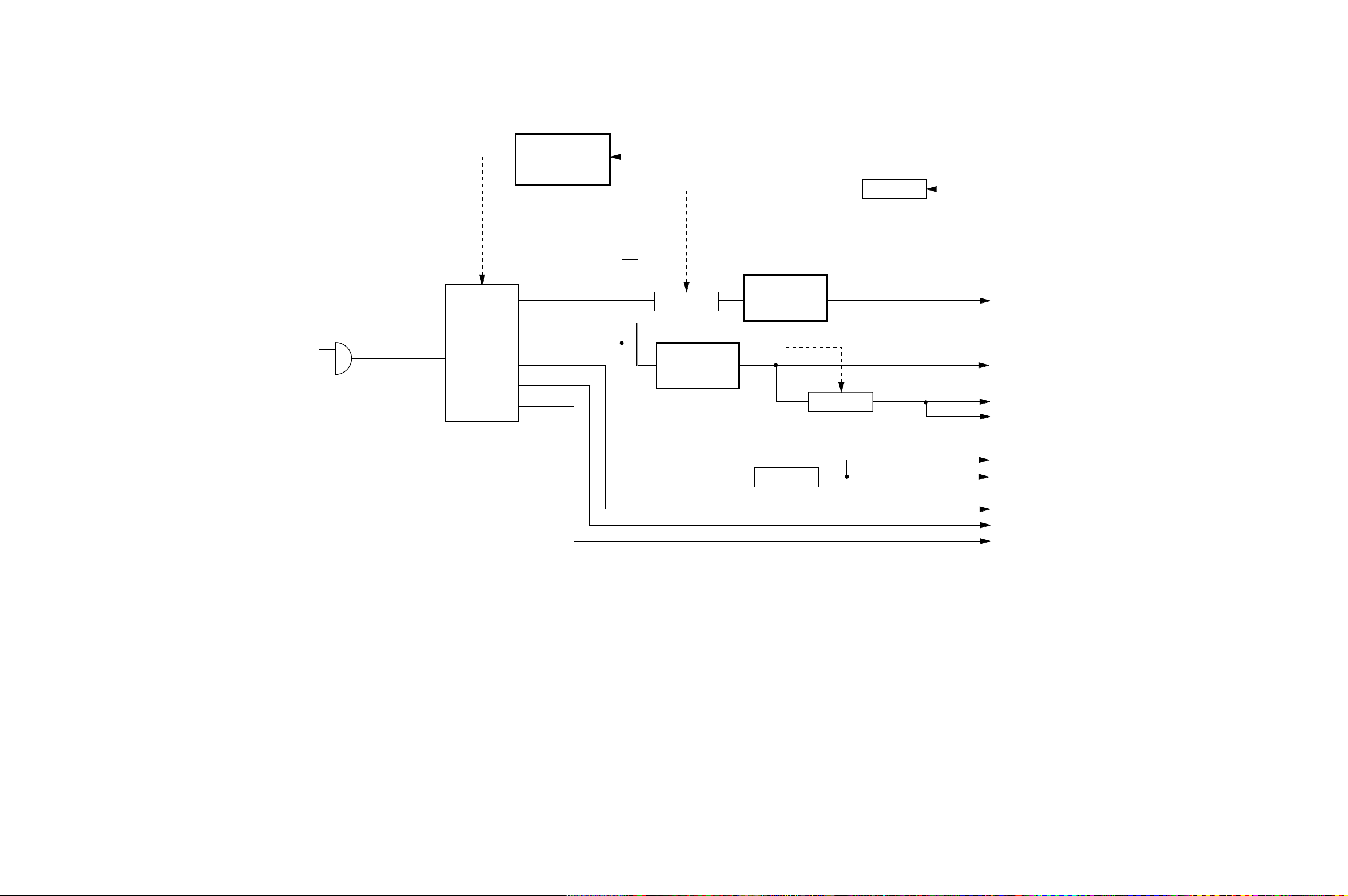
POWER BLOCK DIAGRAM
VOLTAGE CONTROL
IC501
KIA431
Q505
SW
STAND BY L
AC 120V
SWITCHING
REGULATOR
Q501, Q502
T501
Q508
P.CON SW
5V REGULATOR
IC502
KIA7805API
9V REGULATOR
IC503
KIA7809API
Q513
P.CON SW
Q507, Q510, Q512
REGULATOR
P.CON+9V
AT+D5V
P.CON+D5V
P.CON+A5V
P.CON+D3.3V A (AT)
AT+3.3V
-20V
FILAMENT-
FILAMENT+
F-3
F-4
Page 39
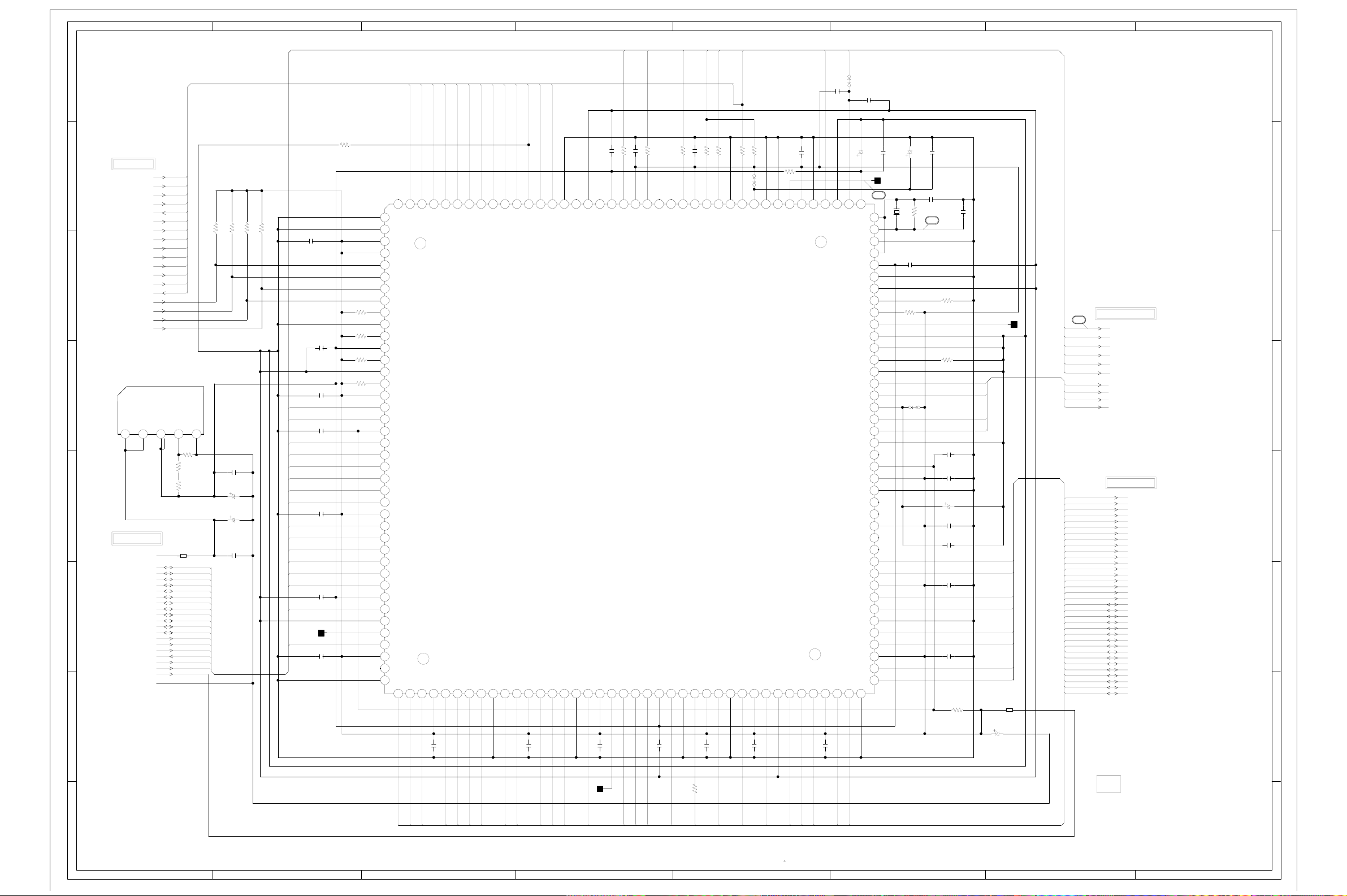
ABC D E F GH
G-1
G-2
MPEG SCHEMATIC DIAGRAM
8
7
6
5
4
3
2
(DVD PCB)
FROM/TO DSP
DVDSTB
DVDSOS
DVDERR
DVDVALID
DVDREQ
DVDDAT0
DVDDAT1
DVDDAT2
DVDDAT3
DVDDAT4
DVDDAT5
DVDDAT6
DVDDAT7
AMCLK
CDERR
CDFRM
CDCLK
CDDATA SPDIF-DVD
1.9V REG.
IC4006 PQ070XZ01ZP
V.OUT
VO
V.IN
12345
FROM/TO SYSCON
P.CON+D5V
P.CON+3.3V
HD7
HD6
HD5
HD4
HD3
HD2
HD1
HD0
HA4
HA3
HA2
HA1
MPGCS#
MPGIRQ#
MPGRST
MPGSTBY
GND
6
R4028
WR
RD
D
1.2 01.94.94.9
510 +-1%
R4027
B4004
FCM2012H-102T04
V.ADJ
R4029
1K +-1%
10
GND
R4001 10K
R4002 10K
R4004 10K
R4003 10K
C4038
0.1 F
C4043
10016V YK
C4041
10016V YK
C4044
0.1 F
ABCLK
ALRCLK
DVDREQ
DVDSTB
DVDSOS
DVDDAT7
DVDDAT6
DVDDAT5
DVDDAT4
DVDDAT3
DVDDAT2
DVDDAT1
DVDDAT0
R4012
4.7K
MPEG_+1.9V
NC NC
0
110
IDLE
4.7K
4.7K
4.7K
4.7K
0
3.3
3.3
3.3
3.3
6
0
0
2.7
9
0
3.3
11
1.9
12
0.7
0
3.2
3.2
2.1
171819 220212223242526272829 330313233343536373839 440
0.9
3.2
1.2
1.6
1.4
1.6
2.8
1.4
3.3
2.7
1.3
0
1.7
3.3
3.3
1.9
1.2
0
1.0
3.3
3.2
2.8
NC
0
C4001
0.1 F
CDERR
CDFRM
CDDATA
CDCLK
HD7
HD6 DAC_D
HD5
HD4
HD3
HD2
HD1
HD0
HA4
HA3
HA2
HA1 MD0
WR MD15
MPGCS#
RD MD14
MPGIRQ# MD13
C4002
0.1 F
C4003
0.1 F
C4004
0.1 F
C4005
0.1 F
C4006
0.1 F
TP4001
C4007
0.1 F
R4023
R4024
R4025
R4026
DVDDA6
DVDDA7
DVDDA5
DVDDA4
DVDDA3
DVDDA2
RAD6
RAD1
DVDDA1
RAD7
HWIO
VDDP
1
HTYPE
HD15
HD14
HD13
HD12
HD11
GND
HD10
VDOC
HD9
GND
HD8
VDOP
HD7
HD6
VDDIP
HD5
HD4
HD3
HD2
HD1
HD0
VDDP
HA3
HA2
HA1
HA0
HWR
HCS
VDDC
HRD
GND
HROY
HIRQ
VDDP
HACK
H0RD
40 GND
RAD3
RAD5
VOOP
C4008
RAD2
0.1 F
RAD4
41 42 43 44 45 46 47 48 49550
0.4 0.4 3.2 0.3 0.4 0.60.3 0.2 0.2 3.2 0.3 0.4 3.0 3.2 3.1 1.9 1.7 3.2 0.5 3.2 0.5 1.3 1.3 3.2 1.3 1.7 001.201.5003.202.000.4
DVDDA0
DVDREQ
GND
RAD0
51 52 53 54 55 56 57 58 59
DVDVALID
DVDSTRB
DVDVALIO
RAD8
VDDP
C4009
0.1 F
DVDERR
DVDSOS
RAD10
DVDERR
RAD9
0
0.30
NC NC
003.302.52.52.41.82.52.22.22.22.21.82.0
GND
GND
GPS1
GPS0
RAD11
GND
RAMCS0
VDDP
3.1 3.1
C4010
R4011 100
R4010 100
C4035 0.1 F
C4034 0.1 F
3.21.61.9
ABCK
VDDC
MPEG
IC4001
ZR36732
RAMCS1
RAMRAS
60 61 62 63 64 65 66 67 68 69770 71 72 73 74 75 76 77 78 79880
0.1 F
1.6
VDDP
RAMCAS
0
NC
ALRCK
RAMWE
C4011
0
AOUT2
VDDC
0.1 F
ASDATA0
R4015 33
AOUT1
AOUT0
RAMDQM
GND
CS
R4016 100
C4036 0.1 F
VDDP
PCLK
C4014
R4017 100
GPIO
VDDP
0.1 F
SPDIF-DVD
AMCLK
AGND
SPDIF
GND
RDA8
AMCLK
R4018 100
R4019 10K
W837
AMCLK
RDA7
C4015
VDDAM
VDDP
0.1 F
TEST
RDA9
GND
GND
R4020
12
C4037
VCLKX2
RDA6
0.1 F
VDDP
RDA10
MPGRST
SCNENABL
120
RDA12
81
RDA5
C4016
C4042
RESTX
GCLK
VDDP
0.1 F
0.1 F
AGND
CVBS-G-Y
RDA11
MPGSTBY
W817
C4039
0.1 F
C4021
1.83.23.33.2001.70 03.21.601.63.23.21.7
12112212312412512612712812913130131132133134135136137138139141401411421431441451461471481491515015115215315415515615715815916160
STBYX
X0
PLLCFG0
GCLK1
VDDC
PLLCFG
GND
AIN
ICEMODE
VREF
VGND
VGND
RSET
VGND
C-B-U
Y-R-V
VDDD
CVBS-C
VGND
CSYNC
VDDIP
VDDP
GND
HSYNC
VDDP
VSYNC
VCLK
RDA0
RDA15
VDDP
RDA1
RDA14
GND
RDA2
RDA13
VDDP
RDA3
RDA4
VDDA
FI
GND
GND
GND
GND
0.1 F
TP4007
27MHZ
0.3
1.6
3.0
0
1.6
C4025
X4001
27MHz
C4024
0.1 F
R4006
10K
W806
MPEG+3.3V
476.3V KA
C4026
C4012 3P CH
1M
R4021
1
R4007
R4008
390 +-1%
0.1 F
MPEG+3.3V
10K
C4027
0.1 F
C4028
0.1 F
C4029
476.3V KA
C4030
0.1 F
C4031
0.1 F
C4032
0.1 F
C4033
0.1 F
R4009
22
C4013
DAC_C
DAC_B
DAC_A
3PCH
V_REF
MD1
MD2
MD3
MD12
B4001
FCM2012H-102T04
C4017
476.3V KA
C4022
18
120
1.4
1.6
0
1.4
1.9
0
0
0
3.2
1.5
110 111 112 113 114 115 116 117 118 119
0
0
1.2
0
0.3
0.2
3.2
0.8
0.2
101 102 103 104 105 106 107 108 109
0
NC
100
3.2
3.2
0
NC
NC
3.2
NC
NC
1.7
90 91 92 93 94 95 96 97 98 99
0.9
3.2
1.2
0.7
0
1.4
1.4
3.2
1.3
81 82 83 84 85 86 87 88 89
1.6
1506.3V ZL
TP4008
3
FROM/TO AUDIO/JACK
AMCLK
ABCLK
ALRCLK
ASDATA0
CS
DAC_A
DAC_B
DAC_C
DAC_D
FROM/TO MEMORY
MA4
MA3
MA5
MA2
MA6
MA1
MA7
MA0
MA8
MA10
MA9
MA11
MCS0#
MRAS#
MPCLK
MCAS#
MWE#
MDQM
MD8
MD7
MD9
MD6
MD10
MD5
MD11
MD4
MD12
MD3
MD13
MD2
MD14
MD1
MD15
MD0
8
7
6
5
4
3
2
RAM_CS1
TP4006
MA4
MA3
MA5
MA2
MA6
MA1
MA7
1
MA0
MA8
MA10
MA9
MA11
MCS0#
MRAS#
MCAS#
MWE#
NOTE:THIS SCHEMATIC DIAGRAM IS THE LATEST AT THE TIME
OF PRINTING AND SUBJECT TO CHANGE WITHOUT NOTICE
MDQM
R4005
MPCLK
100
MD8
MD7
MD9
MD6
MD10
MD5
MD11
MD4
NOTE:THE DC VOLTAGE EACH PART WAS
MEASURED WITH THE DIGITAL TESTER
DURING PLAYBACK.
PCB130
VMB264
1
ABC D E F GH
Page 40

ABC D E F GH
G-3
G-4
8
MEMORY SCHEMATIC DIAGRAM
8
(DVD PCB)
C4047
0.01 B
A16
NC
VSS
DQ15
DQ7
DQ14
DQ6
DQ13
DQ5
DQ12
DQ4
VDD
DQ11
DQ3
DQ10
DQ2
DQ9
DQ1
DQ8
DQ0
DE#
VSS
CE#
FLASH
A15
A14
A13
A12
A11
A10
WE#
A18
A17
7
0.6
110111213141516171819 22021222324
0.9
HA15
0.5
HA14
3
0.6
4
0.7
56789
0.7
0.8
A9
2.9
A8
0
NC
NC
0
NC
NC
3.3
0
NC
NC
0.1
NC
NC
0.1
NC
NC
0
NC
NC
0.1
NC
0.3
2.8
2.8
A7
2.4
A6
0.6
A5
2.8
A4
A2
A1A0
HA4
1.4
1.5
6
5
4
3
2
7
S-DRAM
FROM/TO SYSCON
FLASHCS
RD
HWRH
HD8
HD9
HD10
HD11
HD12
HD13
HD14
HD15
6
5
4
3
HD7
HD6
HD5
HD4
HD3
HD2
HD1
HD0
HA19
HA18
HA17
HA16
HA15
HA14
HA13
HA12
HA11
HA10
HA9
HA8
HA7
HA6
HA5
HA4
HA3
HA2
HA1
P.CON+3.3V
GND
FROM/TO MPEG
MA4
MA3
MA5
MA2
MA6
MA1
MA7
MA0
MA8
MA10
MA9
MA11
MCS0#
MRAS#
MPCLK
MCAS#
MWE#
MDQM
MD8
MD7
MD9
MD6
MD10
MD5
MD11
MD4
MD12
MD3
MD13
MD2
MD14
MD1
MD15
MD0
D
MD15 MD0
MD14 MD1
MD13 MD2
MD12 MD3
MD11 MD4
MD10 MD5
MD9 MD6
MD8 MD7
C4018
0.1 F
MDQM MWE#
4
MPCLK MCAS#
MA9 MA11
MA8 MA10
MA7 MA0
MA6 MA1
MA5 MA2
MA4 MA3
B4003
FCM2012H-102T04
B4002
FCM2012H-102T04
2
IC4002 MSM56V16160F-8
0
VSS
50
0.5
I/O15
0.9
I/O14
00
VSSQ
1.6
I/O13
1.5
I/O12
3.2
VCCQ
1.7
I/O11
1.2
I/O10
0
VSSQ
1.2
I/O9
40 41 42 43 44 45 46 47 48 49
1.5
I/O8
3.2
VCCQ
0
NC
NC
0
DQMU
1.7
CLK
3.2
CKE
0.3
NC
NC
33 34 35 36 37 38 39
0.3
A9
0.2
A8
0.6
A7
30 31 32
0.4
A6
0.3
A5
0.3 0.4
A4
0
26 27 28 29
C4019
0.1 F
1506.3V ZL
C4023
VCC
I/O0
I/O1
VSSQ
I/O2
I/O3
VCCQ
I/O4
I/O5
VSSQ
I/O6
I/O7
VCCQ
DQML
3.3
WE
CAS
RAS
CS
A11
A10
VCCVSS
3.2
110111213141516171819 2202122232425
1.5
1.2
3
4
1.1
5
1.1
6789
3.2
1.4
1.6
0
0.8
0.5
3.2
0
3.1
3.1
3.1
3.0
0.5
2.1
0.2
A0
0.3
A1
0.3
A2
A3
3.2
C4020
MDQM
MRAS#
MCS0#
1506.3V ZL
HA17 HA16
R4030
HD15 HA13
HD7 HA12
HD14 HA11
HD6 HA10
HD13 HA9
HD5
HD12
HD4 HWRH
HD11
HD3
HD10
HD2 HA19
HD9 HA18
HD1 HA8
HD8 HA7
HD0 HA6
RD HA5
C4040
0.1 F
FLASHCS HA3
HA1 HA2
10016V YK
C4045
IC4005 SST39VF800A-70-4C-EK
0.6
3.3
1K
0
1.6
2.0
0.7
0.9
0.7
0.8
40 41 42 43 44 45 46 47 48
0.8
1.6
3.3
1.0
1.2
1.2
1.5
0.6
1.4
1.4
30 31 32 33 34 35 36 37 38 39
1.4
1.2
0
0.1
1.7
25 26 27 28 29
NOTE:THIS SCHEMATIC DIAGRAM IS THE LATEST AT THE TIME
OF PRINTING AND SUBJECT TO CHANGE WITHOUT NOTICE
1
NOTE:THE DC VOLTAGE EACH PART WAS
MEASURED WITH THE DIGITAL TESTER
DURING PLAYBACK.
PCB130
VMB264
1
ABC D E F GH
Page 41
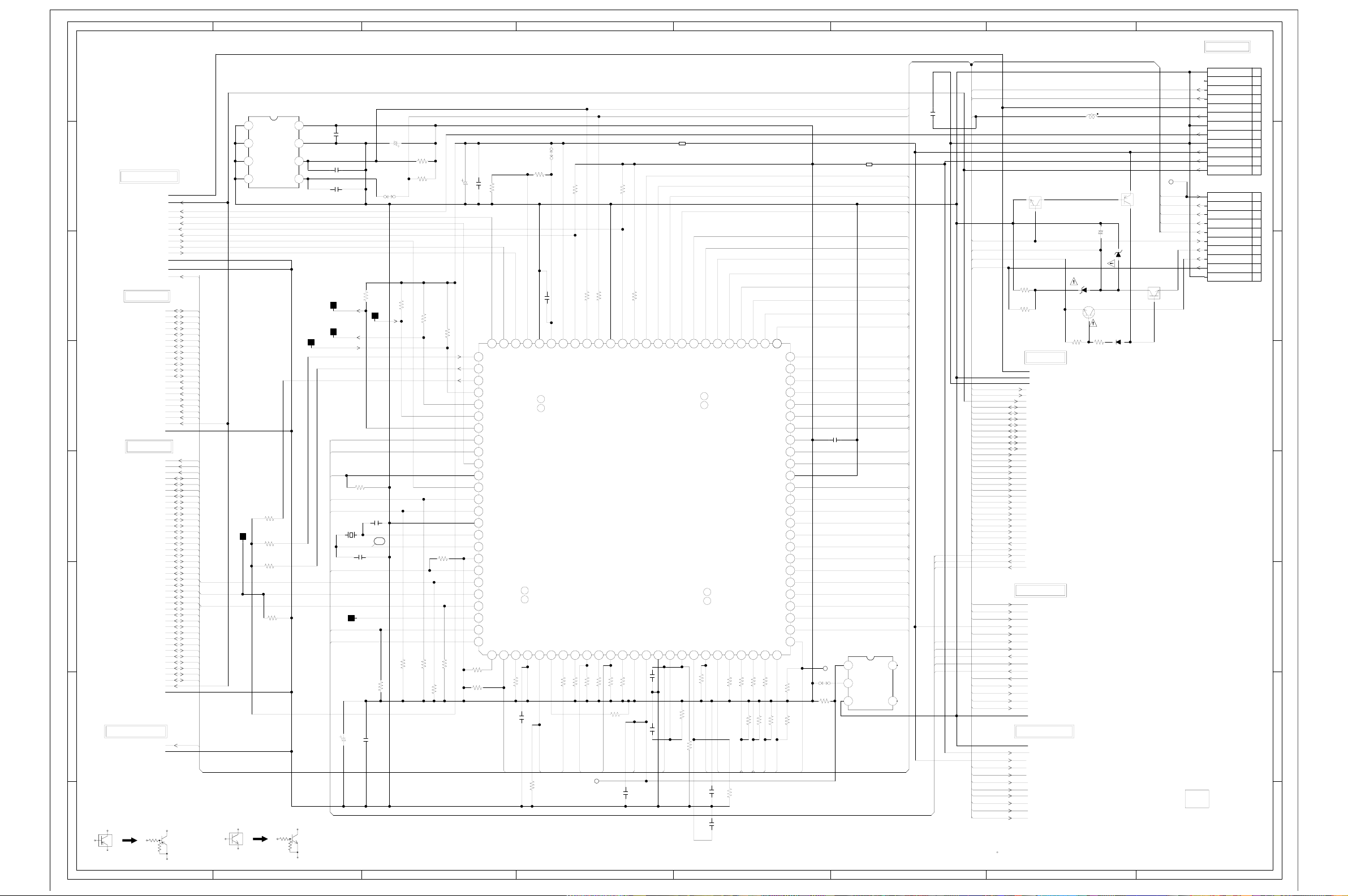
ABC D E F GH
G-5
G-6
SYSCON SCHEMATIC DIAGRAM
8
7
6
5
4
3
2
1
(DVD PCB)
FROM/TO MOTOR DRV
GND[M]
P.CON+3.3V
P.CON+9V
SPD_FG
DMUTE
OPEN
CLOSE
LSW
CLS_SW
OPN_SW
GND
GND
P.CON+A5V
FROM/TO MPEG
HD7
HD6
HD5
HD4
HD3
HD2
HD1
HD0
HA4
HA3
HA2
HA1
WR
MPGCS#
RD
MPGIRQ#
MPGRST
MPGSTBY
P.CON+D5V
P.CON+3.3V
GND HD3
FRO/TO MEMORY
FLASHCS HA11
RD HA10
HWRH HA9
HD8 HA8
HD9 HA7
HD10 HA6
HD11 HA5
HD12 HA4
HD13 HA3
HD14 HA2
HD15 HA1
HD7 HA0
HD6 WR
HD5 RD
HD4 RDY
HD3 DVDCS
HD2 DVDRST
HD1 WRQ
HD0 DVDIRQ
HA19
HA18
HA17
HA16
HA15
HA14
HA13
HA12
HA11
HA10 AT+D5V
HA9
HA8
HA7
HA6
HA5 IRIRQ
HA4
HA3
HA2
HA1
P.CON+3.3V SEG6
GND
FRO/TO READ CHANNEL
P.CON+A5V GND
GND
CAUTION: DIGITAL TRANSISTOR
EEPROM
IC1006 S-24C04BFJ-TB
0
1234
A0 VCC
0
A1
0
A2
0
A3
D
A
D
R1030
4.7K
TP1005
R1002
10K
R1001
MPGIRQ# HD14
MPGRST HD13
MPGSTBY HD12
D
D
10K
R1066
10K
CAUTION: DIGITAL TRANSISTOR
3.3
0
TEST
3.1
SCL
SDA
C1016
3.1
100P CH
5678
TP1002
SI1
10K
R1015 10K
TP1001
C1006
C1003
18P CH
R1032
0.1 F
C1012
4716V YK
R1004
4.7K
R1005
4.7K
W802
R1016 10K
SI2
5
R1020 10K
R1008
R1003
100K
10K
R1010
4.7K
R1009
4.7K
R1034 10K
R1011
4.7K
C1007 2206.3V YK
5.1
3.3
3.3
5.1
3.3
5.1
3.3
0.3
3.2
3.3
3.3
3.3
2.7
4.7
1.7
1.6
3.3
3.3
3.3
3.3
3.2
3.3
3.2
0.1
4.7K
4.7K
R1051
C1013 0.1 F
SI0/PF0
76777879
SO0/PF1
SC0/PF2
SI1/PF3
SO1/PF4
80818283848586878889
SI2/PF5
SO2/PF6
PF7/INT4/ATG#
DACK1/PE7
DACK0/PE6
DREQ1/PE5
DREQ0/PE4
INT3/PE3/SC2
INT2/PE2/SC1
0
VSS
90919293949596979899
X1
X0
VCC
INT1/PE1
INT0/PE0
RAS0/PB0
CSOL/PB1
CSOH/PB2
DWOX/PB3
PB4/EOP2
100
110
3.3 0 3.3 3.3 0 3.3 3.3 3.3 3.3 3.3 0.1 3.3 3.3 3.3 0 3.3 0 0 3.3 3.3 3.3 1.2 3.3 3.3 1.5
R1036
4.7K
R1035
4.7K
RGB_H
R1021
4.7K
AVSS/AVRL
PD0/AN0/STRBIN
PD1/AN1/DRVVLD
7475PD2/AN2/DVDSOS
12DREQ2/PB5/CS1L
DACK2/PB6/CS1H
PB7/DW1#
PA6/CLK
VCC
3
4
5
R1037 4.7K
0.1 F
C1014
CD/DVD
R1038 10K
W808
10K
R1039
R1072 33
R1071 33
C1015 0.1 F
5.1 00
AVCC
AVRH
PD3/AN3/INIT5
PA5/CS5#
PA4/CS4#
8
R1017 33
MPGCS#
A23/P67
P70/A24/EOP0
PA2/CS2#
EOP1/PA3/CS3#
9
R1040 10K
R1041 4.7K
DVDCS
JG1002
10K
R1048
R1050
0.10.13.33.03.05.12.3 3.3 2.6 00 3.3 0 0.3 0.7 0.6 0.7 0.6 0.6 0.8 0.8 0.9 2.8 2.8
VSS
A20/P64
A21/P65
A22/P66
SYSCON
IC1001
ZR36705
NMI#
PA1/CS1#
R1046 4.7K
FLASHCS
HST#
PA0/CS0#
11 12 13 14 15 16 17 18 192 20 21 22 23 24 25
R1049 4.7K
R1047 4.7K
R1012
4.7K
CPU_RESET
C1020
22P CH
C1001
0.1 F
C1017
100P CH
TP1003
SO2
TP1004
SO1
FP_SEL
FP_CLK HA0
DVDRST
R1014
WRQ HD5
IRIRQ HD4
X1001
12.5MHz
C1002
18P CH
DVDIRQ HD15
TP1006
FP_DOUT HD10
FP_DIN
1506.3V ZL
C1004
4.7K
A19/P63
RST#
C1023
C1022
B1001
FCM2012H-102T04
A16/P60
A17/P61
A18/P62
VSS
MD0
MD1
0.1F
R1023
4.7K
0.1F
MODE1
R1053 4.7K
P57/A15
P56/A14
5251P51/A09
24
25 P20/D16
MD2
P80/RDY
R1054 4.7K
RDY
C1008
C1024
565758596606162636465666768697707172737475
55
P55/A13
P50/A08
P85/WR1#
P81/BGRNT#
SYS_MUTE
0.1 F
R1024
0.1F
P54/A12
P82/BRQ
R1055 4.7K
R1069 33
RD
4.7K
P53/A11
P83/RD#
R1070 33
R1067 4.7K
WR
P47/A07
P46/A06
P52/A10
P45/A05
P44/A04
P43/A03
P42/A02
P41/A01
P40/A00
P37/D31
P36/D30
P35/D29
P34/D28
P33/D27
P32/D26
P31/D25
P30/D24
P27/D23
P26/D22
P25/D21
P24/D20
P23/D19
P22/D18
P21/D17
P84/WR0#
R1073 33
R1068 4.7K
HWRH
R1074 4.7K
VCC
VSS
AT+3.3V_M
51525354
2.5
50
2.8
0
0.9
0
2.5
1.3
1.3
1.7
3.3
0.1
2.1
0
40 41 42 43 44 45 46 47 48 49
0.9
0.8
1.6
1.2
1.4
1.6
1.4
1.5
0.7
0.7
30 31 32 33 34 35 36 37 38 39
0.7
1.0
1.2
0.6
26 27 28 29
JG1004
HD9
W807
47K
R1026
R1027
HD8
R1018
10K
47K
HD9
NOTE:THIS SCHEMATIC DIAGRAM IS THE LATEST AT THE TIME
B1002
FCM2012H-102T04
C1009
0.1 F
RESET
IC1002 PST3229NR
3.3
123
3.3
VCC V.OUTGND
0
OF PRINTING AND SUBJECT TO CHANGE WITHOUT NOTICE
(GND_D)
GND
P.CON+12V
SCL
SDA P.CON+A5V
HA19
HA18
HA17 SW_PB
HA16
HA15
HA14
HA13 FILAMENT+
HA12
HA11
HA10
HA9
HA8
HA7
HA6
HA5
HA4
HA3
HA2
HA1
HD7
HD6
HD3
HD2
HD1
HD0
HD11
0.2
NCNC
0.2
4 5
NC NC
C1018
0.01B
P.CON+D5V
MPGSTBY
-20V
FILAMENT-
00
R1056
22K
R1057
100
D
A
FROM/TO DISPLAY
FRO/TO AUDIO/JACK
3.3
FROM/TO DSP
GND[M]
GND
GND
P.CON+D5V
P.CON+A5V
P.CON+3.3V
HD7
HD6
HD5
HD4
HD2
HD1
HD0
HA12
-20V
FILAMENTFILAMENT+
MPGSTBY
FP_SEL
FP_CLK
FP_DOUT
FP_DIN
SW_PB
SEG5
K4
K3
GND
AT+3.3V
AT+D5V
P.CON+12V
P.CON+A5V
SYS_MUTE
SCL
SDA
CD/DVD
RGB_H
P.CON+D5V
GND[M]
L1001
2.2uH
P.CON+9V
(GND_A)
AT+D5V
AT+3.3V
P.CON SW
Q1002
DTC124EKA
MTZJ4.7B
-12.8 -12.1
-12.1
R1059
22K
NOTE:THE DC VOLTAGE EACH PART WAS
5.1
P.ON SW
Q1001
DTA114EKA
1050V
NA
C1021
D1002
D1003
P.CON SW
Q1004
KTC3203_Y
D1005
R1060
MCL4148
22K
MEASURED WITH THE DIGITAL TESTER
DURING PLAYBACK.
5.1
0
MTZJ20B
-20V SW
Q1003
DTC144EKA
-19.3 -19.4
5.1
JG1001
SEG6
SEG5
K4
K3
NC
PCB130
VMB264
FROM/TO POWER
CP1002
(CD502)
A2001WV2-12P
GND
AT+12V
P.CON+12V
P.CON+D5V
GND(M)
P.CON+A5V
GND(D)
P.CON+9V
GND(A)
AT+D5V
AT+3.3V M
P.CON+3.3(AT)
CP1003
(CD503)
52147-1010
SW PB
SEG6
SEG5
K4
K3
STAND BY L
-20V
FILAMENT(+)
FILAMENT(-)
GND
8
1
2
3
4
5
6
7
8
9
10
11
12
7
10
9
8
7
6
5
4
3
2
1
6
5
4
3
2
1
ABC D E F GH
Page 42
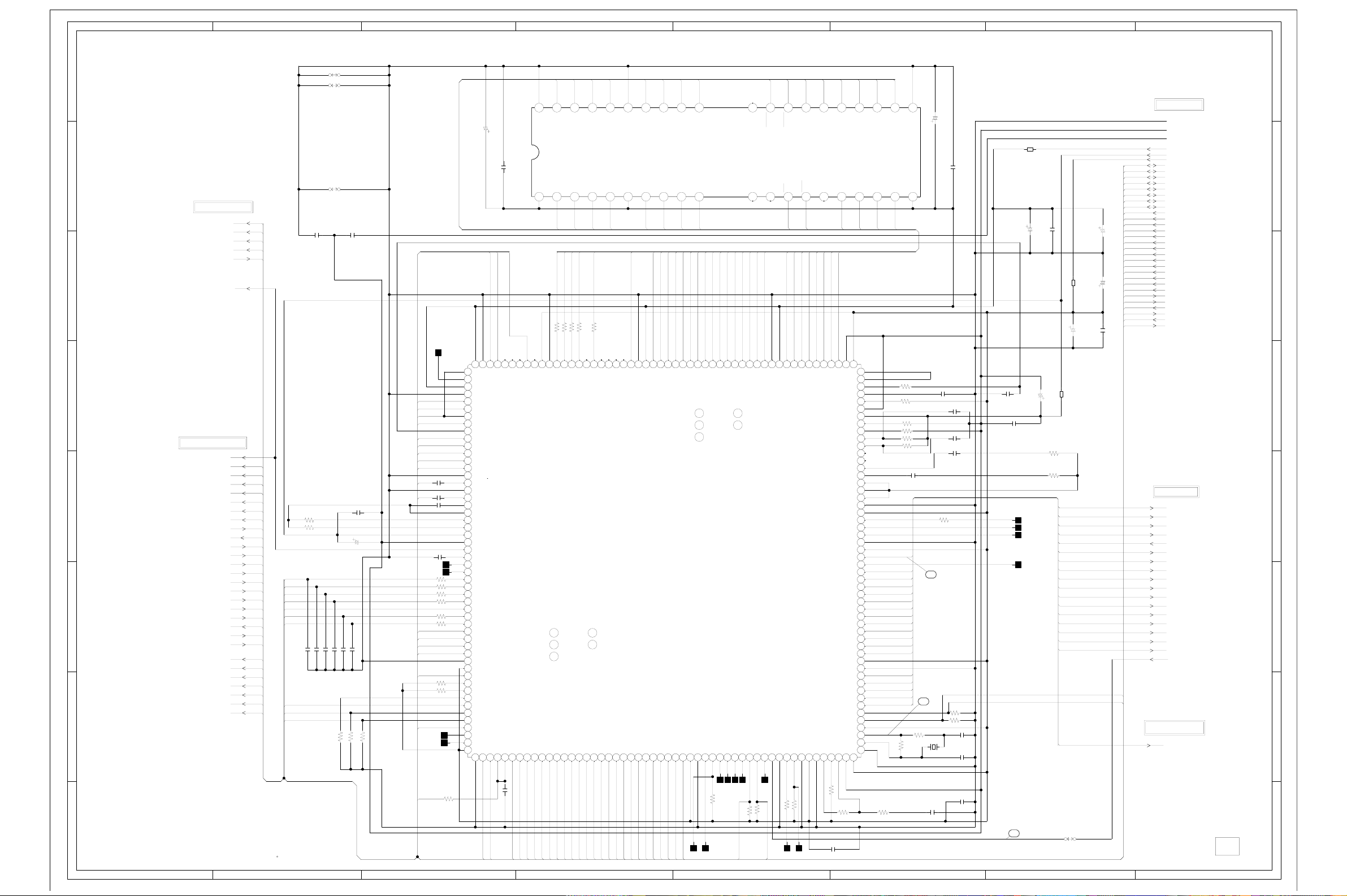
ABC D E F GH
G-7
G-8
DSP SCHEMATIC DIAGRAM
8
(DVD PCB)
7
FROM/TO MOTOR DRV
SPD
SLD
TD
FD
SPD_FG
6
5
FROM/TO READ CHANNEL
4
3
2
NOTE:THE DC VOLTAGE EACH PART WAS
MEASURED WITH THE DIGITAL TESTER
DURING PLAYBACK.
1
NOTE:THIS SCHEMATIC DIAGRAM IS THE LATEST AT THE TIME
OF PRINTING AND SUBJECT TO CHANGE WITHOUT NOTICE
VREF
VREF
TOST
FOST
BOOT3T
RFVCA
TBAL
FBAL
SGC
ADPH
XHTR
BH
BHDC
RFP
RFN
ADWO
ADTE
TE
ADFE
ADRREC
DEFECTO
DEFECTI
ADBCA
LDON1 AMCLK
CDX4
CDX2
LDON2
DPD_TE
XQBH
DEFINH
W850
W851
MD9_A
MD15_A
MD14_A
MD13_A
0
4.3 4.3 4.3
VSS
1506.3V ZL
C2023
C2024
0.1 B
W861
C2006 0.001 B
C2011 0.001 B
C2014 0.001 B
C2013
0.01 B
C2009 0.1 B
C2010
2206.3V YK
C2015 0.001 B
C2016 0.001 B
R2014 15K
R2017 10K
R2016 10K
JV
XHTR
DEFECTI
DEFECTO
TP2001
2.5
110
2.5
4.9
3
0
4
2.5
BH
TE
ADWO
ADBCA
ADRREC
ADPH
BHDC
ADTE
ADFE
RFP
RFN
C2019 0.1 B
C2020 0.001 B
TP2004
TP2002
R2006 1K
R2007 1K
R2008 1K
R2009 1K
R2010 1K
R2011 1K
SLD DVDDAT3
SPD DVDDAT2
TD DVDDAT1
FD DVDDAT0
SPD_FG DVDERR
R2012 10K
R2013 10K
WRQ
TP2005
TP2003
C2017
470P CH
C2018
470P CH
5
2.5
2.5
2.5
0.3
3.2
3.2
111213141516171819 22021222324
2.3
2.5
0.1
0
2.5
0
2.5
2.5
2.5
2.5
2.5
5.0
0
2.5
2526272829
2.5
2.5
2.4
2.5
2.5
30313233343536373839
2.4
3.0
2.5
2.4
2.6
2.5
2.3
2.6
2.5
0
40414243444546474849
3.3
2.2
3.3
2.0
0
0.1
0
3.1
2.7
3.2
50
3.3
5152
3.3
53 545556 57 58 59660 61 62 63 64 65 66 67 68 69770 71 72 73 74 75 76 77 78 79880 81 82 83 84 85 86 87 88 89990 91 92 93 94 95 96 97 98 99
R2064
DVDRST
220
5.0
RFPI
TESTIO
DVDD2
DVSS
AD5
AD4
AD3
AD2
AD1
AD0
RF PH
RF BH
TE
FE
TEST0
EFMINP
TEST1
EFMINN
SLCLPF0
SLCLPF1
SLCO1
SLCO2
AVDD1
AVSS
VREF
SLCBIAS
TESBIAS
HFLBIAS
OFSET
BCATH
BOOT3T
RFVCA
TBAL
FBAL
SGC
SLDO
SPDO
TDO
FDO
DVSS
DVDD0
FG
EVENT
HFLIO
PP0
PP1
PP2
PP3
WRQ
HFBUSYB
HBUSYB
DVDD3
0
3.3
RDY
000
NC NC NC NCNCNC NC
NCNC
000
RFP2
RFP3
RFP4
CEFECTO
DVDRESB
RESB
HRDB
HWRB
3.2
3.3
3.3
1.2
3.3
0.1 B
C2021
DVDIRQ
RD
WR
C2002
0.1 B
R2001
100K
R2002
33K
VREF
TOST CDCLK DVDDAT3
FOST CDDATA
BOOT3T CDERR
RFVCA DVDDAT7
TBAL DVDDAT6
FBAL DVDDAT5
SGC DVDDAT4 CDERR
C2003 0.001 B
DEFINH DVDREQ
CDX2
CDX4
I/O 15
VCC
I/O 0
0
DVSS
DVDD0
53 DVSS
54 HWAITB
HDAT1
HDT2
1.6
1.4
HD1
HD2
MD0_A
MWE
R2020 220
4.9
MWEB
HDAT3
1.2
HD3
MDE
R2021 220
4.6
MOEB
HIRQB55
HDAT4
1.5
HD4
3
MD1_A
MCASL
R2022 220
4.6
MCASLB
HDAT5
0.7
HD5
5.0 4.2 4.5 5.04.5 4.5 4.54.3 4.3 4.3
0
RFP0
RFP1
HCSB
HDAT0
3.3
1.4
DVDCS
HD0
MD12_A
4041424344
I/O 13
I/O 14
I/O 1
I/O 2
4
56789
MD2_A
MD3_A
MCASU
MAASO
R2023 220
R2024 220
5.0
0.2
0.2
4.2
4.6
MA11
MA12
MRAS0B
MRAS1B
MCASUB
103
AVSS
104
AVDD3
HDAT6
HDAT7
HADR0
HADR1
HADR2
0.9
2.1
0.1
1.7
1.4
HD6
HD7
HA0
HA1
HA2
MD11_A
VSS
VCC
MA8_A
2.2
MA8
HADR5
0.8
HA5
0
DVSS
HADR6
2.8
HA6
I/O 11
I/O 4
MD4_A
MA7_A
5.0
2.6
DVDD5
HADR7
1.0
2.9
HA7
HA8
MA6_A
2.6
MA6
MA7
HADR8
HADR9
2.9
HA9
MD10_A
MD5_A
04.3 4.3 4.3 4.3 4.3
I/O 12
I/O 3
0.2
0.2
MA9
MA10
HADR3
HADR4
1.3
2.8
HA3
HA4
MD8_A
I/O 8
I/O 9
I/O 10
I/O 5
MA5_A
2.6
MA5
IC2001
LC78661W
HADR10
0.9
HA10
DRAM
IC2002
MSM5416258B-30
I/O 6
I/O 7
10
MD6_A
MD7_A
MA4_A
MA3_A
MA2_A
MA1_A
MA0_A
MD0_A
MD1_A
MD2_A
MD3_A
2.6
1.4
MA0
DEFECT1
DVSS
DVDD1
PW/FSEQ
3.3
R2025 10K
TP2006
MD0
SBCK
1.5
MD1
SBSY
0.1
TP2007
1.5
1.5
MD2
157
158
SFSY
000
TP2008
2.6
2.6
2.6
2.6
MA1
MA2
MA3
MA4
53
54
55
HADR11
HADR12
DVDD3
DVSS
3.303.3
0.7
0.7
TP2022 TP2012 TP2023
HA11
HA12
MCASL
NC
5.0 5.0 5.0 5.0 5.0 5.0 5.0 5.0
0
323536373839
13 141 15 16 17 18 192 20 21 22
00
NC
NC NC
MD4_A
MD5_A
MD6_A
MD7_A
1.4
1.5
1.5
1.505.0
MD7
MD6
MD5
MD4
MD3
AVDD4
AVSS
FSX
EFLG
PP4
PP5
X16MOUT
3.3
3.201.701.203.301.0
10K
TP2009
TP2010
TP2011
R2027
10K
R2026
DPD_TE
XQBH
CASL
DVSS
X16MIN
MCASU
3031
MWE
MD8_A
1.6
DVDD5
TEST2
R2028 22
MDE
CASH
WE
MAASO
MD9_A
MD10_A
1.5
1.5
MD9
MD8
MD10
DVDCKOUT
DVDCKIN
TEST3
3.3
R2029 10K
OE
RAS
0.1
MD11_A
MD12_A
1.5
1.5
MD11
DVDD0
MA8_A
A8
NC
MD13_A
1.5
MD13
MD12
DVSS
VPDO
101102 103104
100
C2030
0.1 B
MD14_A
MD15_A
1.5
1.503.3
MD14
VCOCTL
EFMOUT
AVERRB
AVSCTB
AVDACK
AVACKOI
AVREQIO
VRPFR
1.2
1.003.3
R2031
R2030 5.6K
MA7_A
A7
A0
MA0_A
JVRVO
JVAIN
MD15
JVAO
JVCPC
JVCP1
AVSS
AVDD2
AVDD2
CDFR
FISET
PISET
PCN
LF3
LF2
LF1
FPDO
PPDO
DVSS
DVDD0
PCK
LEFM
DVSS
DVDD4
DOUT
EMPH
LRSY
ROMCK
ROMXA
C2F
AVD7
AVD6
AVD5
AVD4
AVD3
AVD2
AVD1
AVD0
DVDD4
DVSS
PP7
PP6
DVDD6
XOUT
XIN
VCOC
DVSS
10K
MA6_A
MA5_A
MA4_A
0
23242526272829
A5
A6
A1
MA1_A
157158159160161162163164165166167168169170171172173174175176177178179180181182183184185186187188189190191192193194195196197198199200201202203204205206207208
105106 107108109110111112113114115 116117 118119 120121 122123124125126127128129130131132 133134 135136 137138 139140141142143144145146147 148149 150151 152153 154155 156
0
0
1.4
0
2.6
0
5.0
0.5
0
1.9
1.7
2.9
0
NC
0.4
0
0.3
2.0
2.0
2.0
0
3.3
1.5
1.6
1.6
0
3.3
0
0
3.3
0
0
3.3
2.0
1.6
2.0
2.0
2.0
2.0
2.0
3.3
0.1
3.3
3.3
1.7
2.3
0.1
0
3.3
3.3
1.6
1.6
0
A2
MA2_A
R2035 27K
R2036 10K
R2042 1.2K
R2043 1.8K
R2044 22K
R2045 22K
NC
SPDIF-CD
DVDVALID
R2033
220
A4
VSS
A3
VCC
5.05.05.05.05.05.05.0
MA3_A
C2031 0.1 B
CDFRM
DVDSOS
DVDSTB
6
R2046 150
1M
R2041
1506.3V ZL
C2033
C2041
C2034 0.01 B
C2035
0.1 B
C2036
0.1
C2038 0.1 B
R2037 22
2
R2038 10K
R2039 10K
C2039
15P CH
X2001
C2040
16.9344MHz
15P CH
C2037
C2032
0.1 B
0.1 B
B2003
FCM2012H-102T04
0.1 B
1506.3V ZL
C2045
C2048
C2043
150P CH
C2049 0.1 B
B
7
C2046
R2052 1.2K
R2054 680
TP2015
TP2013
TP2014
TP2018
16MHZ
2206.3V YK
P.CON+A5V
0.1 B
B2002
FCM2012H-102T04
1506.3V ZL
C2050
B2001
FCM2012H-102T04
DVDSTB
DVDSOS
DVDERR
DVDVALID
DVDREQ
DVDDAT0
DVDDAT1
DVDDAT2
DVDDAT4
DVDDAT5
DVDDAT6
DVDDAT7
CDFRM
CDCLK
CDDATA
SPDIF-CD
W810
C2051
C2053
C2052
LDON1
LDON2
8
FROM/TO SYSCON
GND
GND
GND[M]
P.CON+D5V
P.CON+A5V
P.CON+3.3V
HD7
HD6
HD5
HD4
HD3
HD2
HD1
HD0
HA12
HA11
HA10
1506.3V ZL
1506.3V ZL
0.1 B
HA9
HA8
HA7
HA6
HA5
HA4
HA3
HA2
HA1
HA0
WR
RD
RDY
DVDRST
WRQ
DVDCS
DVDIRQ
7
6
5
FROM/TO MPEG
DVDSTB
DVDSOS
DVDERR
DVDVALID
DVDREQ
DVDDAT0
DVDDAT1
DVDDAT2
DVDDAT3
DVDDAT4
DVDDAT5
DVDDAT6
DVDDAT7
CDERR
CDFRM
CDCLK
CDDATA
FROM/TO AUDIO/JACK
SPDIF-CD
4
3
2
1
PCB130
VMB264
ABC D E F GH
Page 43
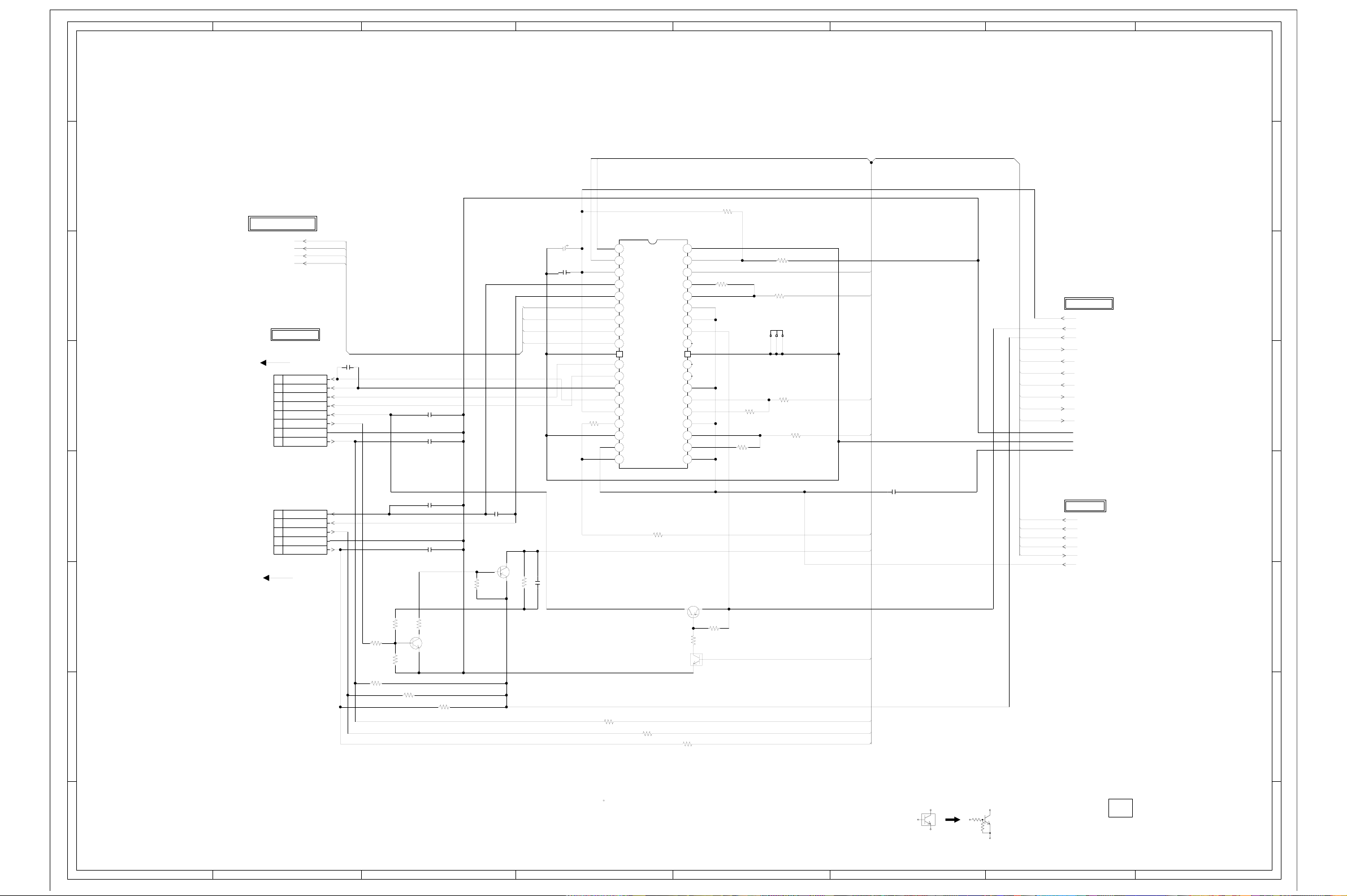
ABC D E F GH
G-9
G-10
8
MOTOR DRIVE SCHEMATIC DIAGRAM
8
(DVD PCB)
7
FROM/TO READ CNANNEL
FO+
FOTR+
TR-
6
FRO/TO LOADER
CD2301
2H081007
SLD1
8
SLD2
5
7
SP1+
6
SP1-
5
+5V
4
SP FG
3
GND
2
LIMIT SW
1
CP2301
00_6232_008_006
C2301
0.1 B
C2303
0.1 B
C2306
0.1 B
C2309
10016V YK
C2310
0.1 B
TRTR+
FOFO+
OPEN
CLOSE
P.CON+9V
MOTOR DRIVE
IC2301 LA6560
0
1101112131415161718
FWD
0
2
REV
9.1
3
VCC2
0.2
456789
VLD-
0.2
VLD+
4.0
VD4+
4.3
VD4-
4.3
VD3+
4.1
VD3-
0
37
5.3
VD2+
3.1
VD2-
4.2
VD1+
4.2
VD1-
9.1
R2308
15K
VCC1
2.5
VIN1
0
VIN1-A
2.5
VIN1+A
2.5 2.5
VIN1-B
S-GND
VCONT
MUTE
VIN4
VIN4VIN4+
VREF-IN
VIN1-SW
VREF-OUT
REG-OUT
REG-IN
VIN3+
VIN3VIN3
VIN2+
VIN2VIN2
VIN1+B
R2314
12K
0
4.2
3.3
R2313
2.5
10K
2.5
2.5
2.6
30 31 32 33 34 35 36
5.0
NC
2.5
0
38
NC
0
0.9
NC
26 27 28 29
2.5
2.5
2.6
2.5
2.5
3.0
20 21 22 23 24 25
19
R2315
22K
R2316
10K
R2318
10K
R2317
5.6K
HS2301
763WSA0022
R2319
10K
R2320
10K
DMUTE
FD
SPD
TD
FROM/TO SYSCON
P.CON+9V
P.CON+A5V
P.CON+3.3V
SPD_FG
DMUTE
OPEN
CLOSE
LSW
CLS_SW
OPN_SW
D
GND
GND[M]
A
GND
7
6
5
C2315
VREF
SLD
DMUTE
LSW
0.1 B
CAUTION: DIGITAL TRANSISTOR
FROM/TO DSP
SPD
SLD
TD
FD
SPD_FG
VREF
PCB130
VMB264
4
3
2
1
4
CP2302
A2001WV2-5P
1
2
3
4
5
CD2302
CU251002
MLD1(-)
MLD2(+)
CLOSE
GND(D)
OPEN
3
R2302
10K
R2301
10K
2
C2305
0.1 B
C2304
0.1 B
22K
R2306
R2321
10K
R2304
1.6
0.4
SPDFG CTL
Q2301
KTC3875S_Y_RTK
0
15K
R2303
10K
R2305
10K
NOTE:THIS SCHEMATIC DIAGRAM IS THE LATEST AT THE TIME
OF PRINTING AND SUBJECT TO CHANGE WITHOUT NOTICE
C2308
0.1 B
SPDFG CTL
Q2304
KTA1504S_Y_RTK
3.0
10K
R2322
2.3
3.3
R2323 1M
R2310 10K
DMVTE CTL
C2307 0.0022 B
R2309
100
R2311
100
Q2302
2SA1037AK
5.0
4.9
R2307
4.2
10K
1K
R2324
0
DMVTE CTL
Q2303
KRC102SRTK
3.3
0
R2312
100
NOTE:THE DC VOLTAGE EACH PART WAS
MEASURED WITH THE DIGITAL TESTER
DURING PLAYBACK.
P.CON+A5V
SPD_FG
CLS_SW
OPN_SW
1
ABC D E F GH
Page 44
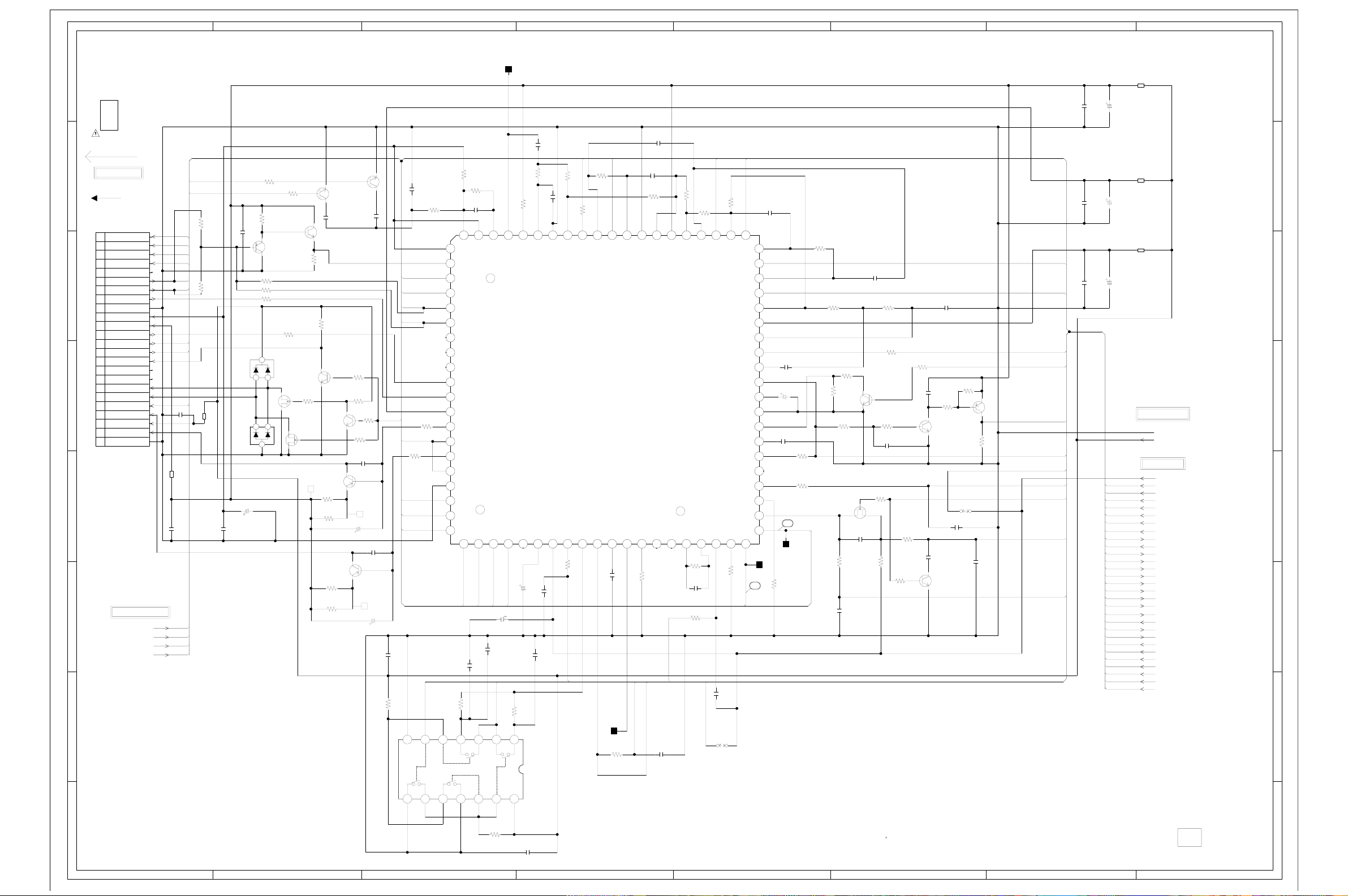
8
G-11
G-12
7
6
5
4
3
2
DVD LOADER
DK4001
DVD-KDR777SK
FRO/TO LOADER
CD2601
2H0O2303
0.5mm PITCH FFC
CP2601
24FLT-SM1-TB
24
23
22
21
20
(NC)
19
18
17
16
GND-PD
15
14
VCC
13
12
11
10
CD/DVD
9
(NC)
8
(LD-CD)
7
VR-CD
6
VR-DVD
5
4
LD-CD
3
2
LD-DVD
1
GND-LD
FROM/TO MOTOR DRV
ABC D E F GH
READ CHANNEL SCHEMATIC DIAGRAM
TP2602
(DVD PCB)
(GND_A)
GND
C2626
C2619
150P CH
CDX2 CTL
KTC3875S_Y_RTK
0.1
KTC3875S_Y_RTK
0
C2605
PD CTL
Q2614
KTC3875S_Y_RTK
2.2K
R2670
10K
R2671
DPD TE CTL
Q2615
KTC3875S_Y_RTK
0
0
DPD TE
Q2616
KTC3875
S_Y_RTK
R2608
22
R2609
22
R2610
22
R2611
22
CDX4 CTL
Q2601
82P CH
0.7
CTL
3.9
4.6
Q2606
0.1
5.0
C2608
2.6
R2643 2.2K
R2650 2.2K
R2607 82K
D2601
KDS121RTK
D2602
KDS120RTK
C2602
4716V YK
0.1 B
R2604
1K
R2667
3.2
0.1 B
0
KTA1504S_Y_RTK
123
123
2.2K
PD CTL
Q2605
R2606
S
D
R2605
1K
3.2
82K
CD CTL
Q2612
2SK3018
G
S
D
4.9
2.6
R2669
100K
DVD CTL
2SK3018
G
Q2613
RF5
CDX2
CDX4
R2631
2.2K
FOFO+
TR+
TR- XQBH
NC
PD1
PD2
R2642
2.2K
PD3
PD4 DEFECTO
NC
NC
LDS1_2
C2653
B2601
0.1 B
FCM2012H-102T04
B2606
FCM2012H-102T04
C2658
0.1 B
FO+
FO- ADBCA
TR+
TR-
C2659
VC
HFM
FF+
T+
T-
B
A
E
F
D
C
MD
0.70
R2673
10K
R2674
10K
0
0.6
0
R2672
100K
C2609
0.001 B
2.6
DVD LD CTL
Q2603
2SA1036K
C2611
1016V KA
DVD LD CTL
Q2604
2SA1036K
R2675
10K
DVD
C2610
0.001 B
5.0
C2612
1016V KA
0
0
C2615
39P CH
R2620
560
C2613
DPD_TE
CD
PVR
47P CH
2.5
2.6
2.7
PD1
2.7
PD2 XHTR
2.7
PD3
2.7
PD4
0.4
NC
0.4
NC
0.4
NC
2.5
PD8
2.5
PD9
4.9
R2617
4.9
1K
LDS1_2
R2618
1K
SGC
FBAL
TBAL RFP
C2614
0.1 B
DEFECTO
10K
R2614
0 0 0.1 2.5 2.5 2.5 2.5
VSS
89
0
1K
R2621
R2623
470
C2616
56P CH
110111213141516171819 220
RFN
RFP
PD1
PD2
5
PD3
6
PD4
PD5
PD6
9
PD7
PD8
PD9
VCC
LDD1
0.2
LDS1
3.8
LDD2
0.2
LDS2
0
GND
1.8
SGC
2.5
FEBL
2.6
TEBL
2.4 2.0 2.7 2.7
R2622
10 11 12 13 14
CA0
PREF
EQ01
80 CAN
VGA21
BST
FOST
BOOT3T
C2656
150P CH
FOST
0.1 B
ADFE
234567
TOST
TOST
C2618
2206.3V YK
R2626
VDD
5.05.05.000.15.0
21 22 23 24 25 26 27 28 29330 31 32 33 34 35 36 37 38 39440
RFVCA
C2617
27K
330
R2627
10K
R2603
C2623 33P CH
GND
EQL1
RFSCT
BCATH
REFI
SREF
2.5 2.5NC3.2 2.6 2.5 2.5 2.5 1.2 2.4 2.6 2.5 2.5 2.6 1.2 2.5
0.7
150V KA
C2620
C2622
150P CH
C2621
150P CH
27K
1
DEFE CTL
IC2601 BU4066BCF
R2628 330
EQ02
RREC
R2629
ADRREC
LDON1
R2619
LDON1
FE
27K
R2630
330
2.2
LDON2
EQI2
READ CANNEL
IC2602
LA9702WL
TE
C2625
TP2021
R2632
6.8K
LDON2
THC
68P CH
C2627
220P CH
R2634
330
EQI1
EQ01
PP/TE
WO
WOI
ISET
56K
R2633
0.1 B
TE
ADTE
C2629
560P CH
VCC
WOO
NCNC
TBAL
150
R2638
RF01
40 RFON
TEO
R2639
68K
C2631
33P CH
R2615
12K
R2640
330
RF02
TEN
ADWO
DPD_TE
C2633
W814
DPD/TE
CP
47P CH
R2644
R2645
EQI3
BHI
330
EQO3
XQBH
EQI4
XHTR
EQO4
EQL2
EQO2
DEFC
RFOP
22K
CDX2
616263646566676869770717273747576777879880
VCC
CPOF
LPC
GND
DEF
BCA
PHI
RFN
3.12.52.62.64.92.502.402.43.2 3.22.502.54.92.52.72.52.7
TH
TC
PH
BH
TP2019
19
C2634
100P CH
60
2.5
3.3
2.5
5.0
2.5
5.0
2.5
0
2.5
0
50 51 52 53 54 55 56 57 58 59
2.5
0
1.2
3.5
0
NC
5.1
3.2
1.2
2.3
41 42 43 44 45 46 47 48 49
2.5
82P CH
R2646
C2637
56P CH
C2635
4716V YK
C2636
TP2020
47K
R2651
330
C2641
33P CH
R2652
330
R2655
33K
47K
R2653
R2656
47K
R2647
2.2K
R2649
47K
20
BH SW
Q2607
2SK3018
0.0047 B
R2654
C2639
47K
220P CH
S
C2640
0
0
3.0
G
2.32.3
R2657
330
R2662
2.2K
TE CTL
Q2608
KTC3875S_Y_RTK
0.6
R2659
100K
C2642
22P CH
R2666
22K
D
R2661
33K
R2658
R2660
22K
P.CON+A5V
0
27K
0.7
R2663
10K
C2643
4.9
DEFECT CTL
0
KTC3875S_Y_RTK
C2645
0
BH SW
Q2610
KTC3875S_Y_RTK
0
C2644
18P CH
470P CH
R2664
22K
Q2609
150P CH
RF5
C2646
220P CH
R2665
22K
4.9
W815
R2668
C2647
0
0
47P CH
DEFECT CTL
Q2611
KTA1504S_Y_RTK
22K
DPD_TE
DEFECTI
DEFINH
ADBCA
ADPH
XHTR
BHDC
SE5
DP5
C2652
C2648
0.1 B
C2650
0.1 B
C2654
C2651
0.1 B
C2655
BH
B2602
FCM2012H-102T04
4716V YK
B2604
FCM2012H-102T04
4716V YK
B2605
FCM2012H-102T04
4716V YK
FROM/TO SYSCON
GND
P.CON+A5V
FROM/TO DSP
VREF
TOST
FOST
BOOT3T
RFVCA
TBAL
FBAL
SGC
ADPH
XHTR
BH
BHDC
RFP
RFN
ADWO
ADTE
TE
ADFE
ADRREC
DEFECTO
DEFECTI
LDON1
CDX4
CDX2
LDON2
DPD_TE
XQBH
DEFINH
8
7
6
5
4
3
2
1
R2625
10K
C2649
0.1 B
NOTE:THIS SCHEMATIC DIAGRAM IS THE LATEST AT THE TIME
OF PRINTING AND SUBJECT TO CHANGE WITHOUT NOTICE
NOTE:THE DC VOLTAGE EACH PART WAS
MEASURED WITH THE DIGITAL TESTER
DURING PLAYBACK.
PCB130
VMB264
1
ABC D E F GH
Page 45

ABC D E F GH
G-13
G-14
AUDIO SCHEMATIC DIAGRAM
C7022
C7006
L7002
1.8uH
B7001
FCM2012H-102T04
47016V YK
C7055
2216V
KA
R7072
470
KA
D7001
MCL4148
330P CH
C7065
R7071
D7002
C7007
100P CH
470
R7048
MCL4148
330P CH
R7049
10K
4706.3V YK
D7007
D7010
10K
9
4.8
0
C7023
MCL4148
MCL4148
10
8
R7050
KRC103SRTK
0
4706.3V YK
3.3K
MUTE SW.
Q7003
4.8
C7057
W829
L7005
L7007
0.27uH
C7027
10P CH
C7028
MUTE SW.
4.8
KRA101SRTK
0
R7051
1K
MUTE SW
KTC3875S_Y_RTK
R7052
4.750V KA
D7009
Q7004
Q7006
W803
0.27uH
10P CH
1K
D7008
MCL4148
0
0
0
C7012
75 +-1%
R7007
11
34
12
56
MCL4148
MUTE SW
Q7005
KTC3875S_Y_RTK
-0.3
8
75 +-1%
75 +-1%
R7041
R7055
2.250V KA
1K
C7041
C7001
C7003
270P CH
270P CH
C7035
0.1 F
82 +-1%
0.1 F
C7054
KA
C7070
C7002
22P CH
L7001
1.8uH
C7005
22P CH
C7038
2216V
2.250V
FROM/TO SYSCON
GND
AT+D5V
P.CON+D5V
P.CON+12V
SYS_MUTE
AMCLK
ABCLK
ALRCLK
ASDATA0
DAC_A
DAC_B
DAC_C
DAC_D
SPDIF-CD
SCL
SDA
P.CON+A5V
CD/DVD
AT+3.3V
RGB_H
CS
ZERO
SPDIF
W836
S/COMP
R7014
10K
R7004
10K
D7011
R7021
MUTE SW
Q7007
KRC104SRTK
C7068
2.250V NA
C7067
2.250V NA
SB040
4.7K
MUTE DET
KTC3875S_Y_RTK
R7010
1K
D7004
MCL4148
3.2
2.6
0
R7022
10K
R7056
100K
R7057
100K
820P CH
820P CH
C7032
R7017
10K
C7026
7
FROM/TO MPEG
6
SPDIF-DVD
FROM/TO DSP
5
4
Q7002
R7011
C7004
0.6
470K
R7058
R7059
0.3
2206.3V
1K
1K
L7011 100uH 0305
10K
R7016
0
D7003
YK
3310V KA
C7071
56
R7026
C7016
MCL4148
C7040
0.0015 B
R7030
10K
0
6.2 6.2 6.2 12.5
C7039
0.0015 B
R7028
10K
C7042
10
10
R7023
R7053
5.1
D AUDIO DRIVER
Q7009
1.7
KTC3875S_Y_RTK
100P CH
100P CH
1.7
C7056
R7035
1.5
+
1.5
D AUDIO DRIVER
Q7010
KTA1504S_Y_RTK
0
10
R7029
220P CH
R7040
12K
R7036
1234
VCC
R7038
12K
10K
4716V YK
C7064
0.022 B
C7036
C7044
6.2 6.2 6.2
A_GND
+
-
5678
100P CH
R7001
R7002
R7054
150 +-1%
C7069
R7039
10K
IC7004 NJM4580MAUDIO_AMP
1K
3
C7014
22P CH
L7004
270P CH
12
R7060 470
0
0
C7052
(DVD PCB)
13
1.8uH
J8001MDC-070V Y/C SEPA
C7008
75 +-1%
R7006
R7047 470
J7001
MSP-244V10-44PBS
CVBS/AUDIO/D.OUT
470P CH
C7053
470P CH
DAC_C(B)U
14
C7013
270P CH
E
1
23
33P CH
DAC_B(R)V
C7010
H1H2EH1H2
16
33P CH
C7015
330P CH
234
1
E
J7003
MSD-243V-18-PBSN
YUV_OUT
C7009
22P CH
L7006
1.8uH
4
W813
56
B7011
D7016
MCL4148
D7017
DAC_A(G)Y
HHH
C7011
FCM2012H-102T04
C7025
6.3V
470
MCL4148
15
330P CH
C7024
4706.3V YK
8
NC NC
1
34 5678
2
S/CVBS COMP
YK
D7018
MCL4148
L7003
MCL4148
W816
C7066
100uH
0305
0.01 B
C7062
C7063
0.1 F
C7017
33P CH
D7014
D7015
D7019
MCL4148
MCL4148
HL
DAC_A[G]Y
OPT TRNSFORMER
OS7001
GP1FA550TZ
1
INPUT
2
VCC
3
GND
476.3V KA
11 12
13 14 15 16 17 18
R7012 10K
W828
SW7001
SK42H0IG9A
NCNC
7
6
5
4
3
226.3V KA
226.3V KA
C8536
C8506
B8501
FCM2012H-102T04
AUDIO_L
AUDIO_R
B8502
FCM2012H-102T04
2
1
0.1 F
2.6 2.6 5.2 3.2 0 3.1 3.1 3.1
VOUTRAGND
PCM1748E
STEREO DAC
IC8503
9
C8503
NOTE:THE DC VOLTAGE EACH PART WAS
MEASURED WITH THE DIGITAL TESTER
DURING PLAYBACK.
VOUTL
VCOM
10 11
1016V KA
C8537
VCC
ZEROR/ZEROA
12 13 14 15 16
NC
ZERO
0.1 F
C8538
VDD
DGND
ZEROL/NAMDMC
SDA
SCL
LRCK
2345678
CS
DATA
ML
C8534
C8535
1
BCK
0.1 F
VCC
4716V YK
000 00003.2
NC
13141516
X
X1
X2
101112
X0
A
X3
R8520
1K
9
B
2
SCK
3.12.93.03.03.02.92.60
ASDATA0
AMCLK
ABCLK
DIGITAL AUDIO SW
ALRCLK
NOTE:THIS SCHEMATIC DIAGRAM IS THE LATEST AT THE TIME
OF PRINTING AND SUBJECT TO CHANGE WITHOUT NOTICE
Y2
Y0
IC8504 SN74LV4052APW
1
1.6 0
SPDIF-DVD
Y
2345678
1.6 00000
SPDIF
Y3
SPDIF-CD
Y1
Inhibit
VEE
GND
CD/DVD
CAUTION: DIGITAL TRANSISTOR
CAUTION: DIGITAL TRANSISTOR
1
PCB130
VMB264
ABC D E F GH
Page 46
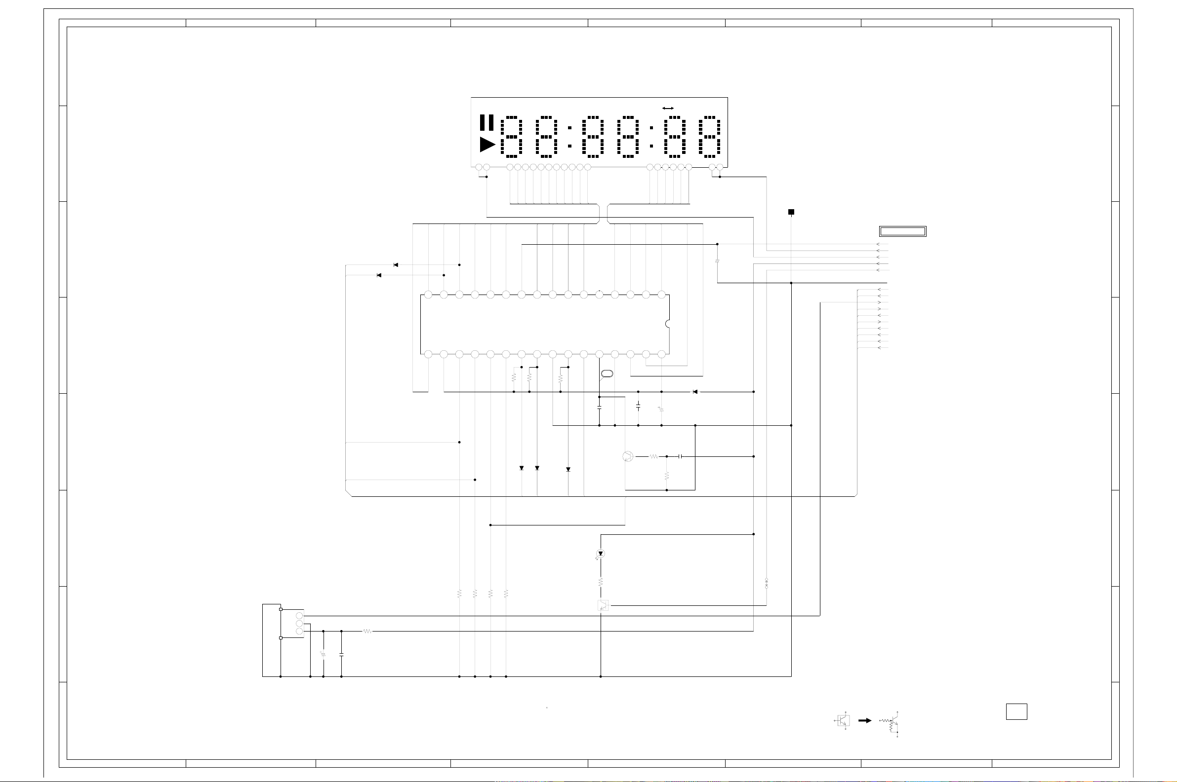
ABC D E F GH
G-15
G-16
8
DISPLAY SCHEMATIC DIAGRAM
8
(DVD PCB)
V651 HNV-06SS71
DVDCD
7
1
P1
P2
P3
P4
P5
P6
6
D651
MCL4148
D652
MCL4148
-17.6 -14.3 -7.8 -8.1 -12.6 -19.7 -15.6 -9.4 -12.6 -12.6 -18.3 -18.3 -18.3 -18.3
-16.0
S5
S6
S8
S9
K2
S3 S4
VDD
17 18 19220 21 22 23 24 25 26 27 28 29330 31 32
K3
K4
00 00 03.7 0.6 3.2 2.5 -18.3-17.7 5.1
SEG6
SEG5
5
TRACK ALL REPEAT A B
10 11 12 13 14 152 23 24 25 26 27 28 31 3256789
P9P8P7P6P5P4P3P2P1
P11
P10
P7
P8
P9
P10
P11
S10
VEE
S13/G14
S14/G13
S15/G12
VSS
R666
SI
10K
R664
SCK
CS
4.9
10K
10K
R665
K1
-19.5
S16/G11
SO
NC
C656
G9
OSC
6G
456789
G8
VSS
17
0.001 B
5G
G7
G3
-18.3 5.10
C661
1G2G3G4G5G
4G
3G
110111213141516
G5
G6
G4
VDD
1506.3V ZL
0.1 F
C663
6G
2G
FIP DRIVER IC
IC651 BU2977FS
D658
SB040
7
CP661
005P-2100
1G
1050V NA
C672
FROM/TO SYSCON
-20V
FILAMENTFILAMENT+
AT+D5V
MPGSTBY
GND
FP_SEL
FP_CLK
IRIRQ
FP_DOUT
FP_DIN
SW_PB
SEG6
SEG5
K4
K3
6
5
4
K4
D654
D655
MCL4148
FP_SEL
MCL4148
FP_CLK
K3
D656
FP_DIN
KTC3875S_Y_RTK
MCL4148
FP_DOUT
RESET SW
Q652
3.0
0
SW_PB
0
(KEY_AD)
R658
C664
1K
0.1 F
100K
R659
3
D657
POWER ON LED
LTL-1CHGE-002A
270
R651
10K
10K
OS651
PIC-37043LO
Vout
1
GND
2
2
B+
3
476.3V KA
C674
C651
R678
100
0.1 F
NOTE:THIS SCHEMATIC DIAGRAM IS THE LATEST AT THE TIME
OF PRINTING AND SUBJECT TO CHANGE WITHOUT NOTICE
R652
10K
R653
R661
R662
10K
1
POWER ON LED SW.
0.1
0
Q653
KRC102SRTK
3.3
NOTE:THE DC VOLTAGE EACH PART WAS
MEASURED WITH THE DIGITAL TESTER
DURING PLAYBACK.
W804
CAUTION: DIGITAL TRANSISTOR
PCB130
VMB264
4
3
2
1
ABC D E F GH
Page 47
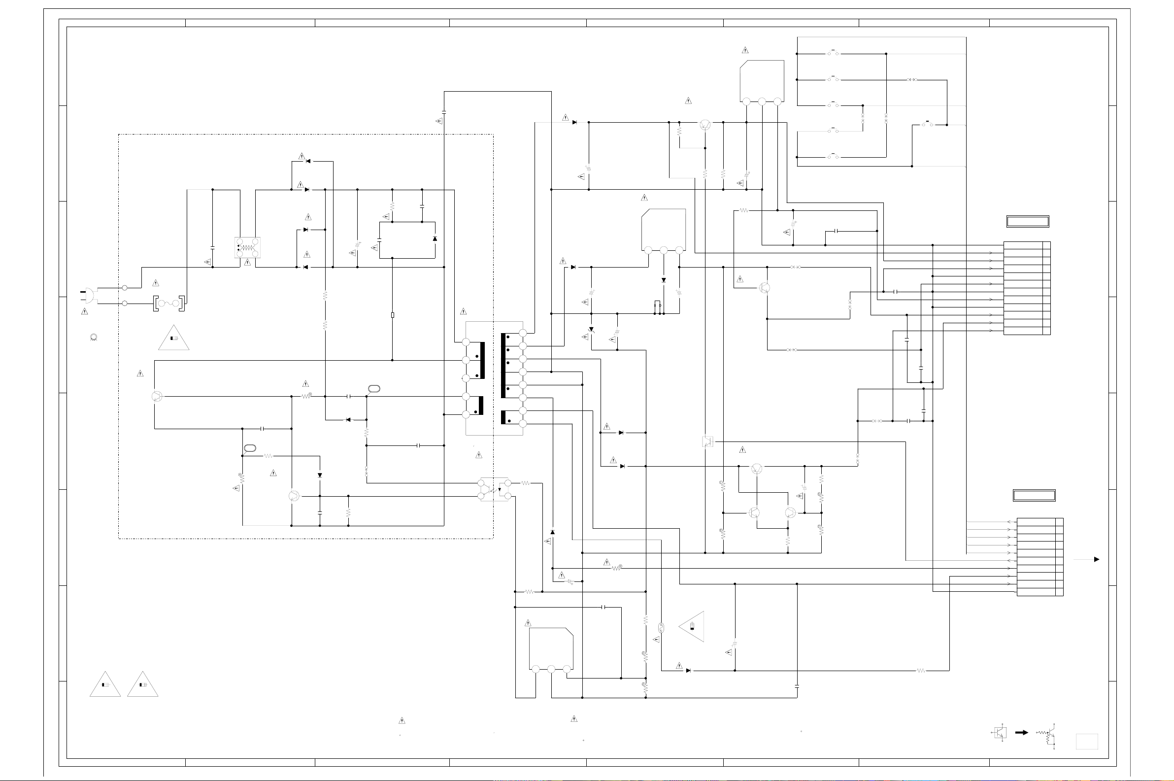
G-17
G-18
ABC D E F GH
8
7
6
5
WHITE
BLADE
WIDE
BLACK
CD501
0R419905
AC120V_60Hz
L502
W5T_20*10*10A
S502_1
S501_1
SWITCHING
Q501_2
2SC5368
FH501_1
EYF-52BC
300
0
F501_1
1.6A125V
1.6A 125V
0.5
FH502_1
EYF-52BC
4
3
2
1.6A 125V
CAUTION:FOR CONTINUED PROTECTION AGAINST FIRE HAZARD,
1
ATTENTION:POUR UNE PROTECTION CONTINUE LES RISQUES D’INCEIE
3A 125V
REPLACE ONLY WITH THE SAME TYPE FUSE
1.6A 125V(F501),AND 3A 125V(ICP502).
N’UTOLISER QUE DES FUSIBLE DE MEME TYPE
1.6A 125V(F501),ET 3A 125V(ICP502).
CAUTION:ICP502 IS MANUFACTURED BY SKYGATE,TYPE 20N.
ABC D E F GH
C502_1
0.1275V PHE840
34
12
L501
0R3A433F20
C505
0.01 Y
51
PROTECT CONTROL
R502
1.5 1W
R508
1001/4W
Q502
2SD734
D505
1N4005-EIC
D502
1N4005-EIC
D503
1N4005-EIC
D506
1N4005-EIC
R505
220K 1/2W
R506
220K 1/2W
R504
68 1W
0.5
0.1
0
0.01 M
1SS133
D504
1SS133
C508
0.0056 X
CRITICAL FOR SAFETY,USE ONES
DESCRIBED IN PARTS LIST ONLY
C509
D526
R507
C511_1
3.9K1/4W
R510
SEG6
K4
8
K3
SW_PB
7
SEG5
FROM/TO SYSCON
CD502
(CP1002)
CU2C2501
P.CON+12V
P.CON+D5V
P.CON+A5V
AT+3.3V M
P.CON+3.3V(AT)
GND
AT+12V
GND(M)
GND(D)
P.CON+9V
GND(A)
AT+D5V
1
2
3
4
5
6
7
8
9
10
11
12
6
5
0.01 Y
0.01 Y
4
FROM/TO SYSCON
CP503
(CP1003)
SW_PB
SEG6
SEG5
K4
K3
B2013H02-10P
SW_PB
SEG6
SEG5
K4
K3
STAND BY L
-20V
FILAMENT(+)
FILAMENT(-)
GND
10
9
8
7
6
5
CD503
4
WHL6008038
3
2
1
3
2
CAUTION: DIGITAL TRANSISTOR
PCB020
VPB158
1
1/4W
100
C529
OPEN/CLOSE
SW661
EVQ21505R
PLAY
SW662
EVQ21505R
STOP
SW665
EVQ21505R
SKIP_F
SW663
EVQ21505R
SKIP_R
SW664
EVQ21505R
33016V YK
C528
1.8
C542
0.01 Y
1/4W
82
R532
226.3V KA
820
R533
R534
1.2K
0.01 F
W822
W813
W811
W819
+-1%
+-1%
NOTE:THE DC VOLTAGE EACH PART WAS
MEASURED WITH THE DIGITAL TESTER
DURING PLAYBACK.
W824
C543
0.01 Y
W825
C546
C541
0.01 Y
POWER SW
SW651
EVQ21505R
0.01 Y
C545
C544
R539
1.8 1/2W
POWER SCHEMATIC DIAGRAM
9V REG.
IC503 KIA7809API
(POWER PCB)
R509
3.1
R522_1
R523_1
IN GND OUT
123
12.4 0 9.0
10016V YK
C531
820 1/4W
R529
5601/4W
P.CON5V SW
Q513
KTC3203_Y
5.9
3.3V OUT
Q510
KTA1281_Y
3.2
3.9K +-1%
3.1
1.8
1.0
3.3V CTL
Q507
2.2K +-1%
KTC3198
3306.3V YK
C527
5.3
5.0
3.43.9
3.3V CTL
Q512
KTC3198
C535
W808
W809
3.9
1.0
R528
P.CON SW
Q508
R524
OUTIN GND
5.3
SB040
C526
P.CON SW
KRC101MAT
3A 125V
20N_3000FS
D516
10ELS2N
2SB1131
4.7K
22006.3V YK
Q505
1/4W
11.6
R526
0.1
0
3A 125V
12.4
560 1/2W
C516
0.0047250V KX
C514
0.0056 X
ARESINCE THESE PARTS MARKED BYCAUTION:
C515
0.01500V E
D509_1
RGP10J-EIC
325
325
NC
22.3
T501
81220124
1
2345
0
PHOTO COUPLER
IC504
LTV-817M-VB
16.4
3.8
34
0
0
0
0
10 11 12 13
0
0
0
0
6789
R514
3.3
1
4701/4W
2.3
2
R515
1K1/4W
VOLTAGE CTL
IC501 KIA431
2.2 0 2.5
DANGEREUSES AN POINT DE VUE SECURITE
N’UTILISER QUE CELLS DECRITES
DANS LA NOMENCLATURE DES PIECES
100K1/2W
R512_1
100P1KV B
C513
82200V WA
W4BRH3.5X6X1.0X2
B501
52
1/4W
150
W803
D511
10ELS2N
GNDOUT IN
D512
SB290S
D510
SB290S
C518
4750V YK
123
C523
220025V YK
5V REG.
IC502 KIA7805API
123
8.0 0
YK
C521
220016V
D528
MTZJ5.6B
C540
0.01 M
C522
D514_1
SB140-EIC
D527
SB140-EIC
R531
220 1W
22006.3V YK
ETANTLES PIECES REPAREES PAR UNATTENTION:
D507
HS502
763WAA0186
120 1/4W
R516
ICP502
R517
1K +-1%
R518
2.2K +-1%
NOTE:THIS SCHEMATIC DIAGRAM IS THE LATEST AT THE TIME
OF PRINTING AND SUBJECT TO CHANGE WITHOUT NOTICE
Page 48

ABC D E F GH
G-19
G-20
8
S/CVBSCOMP
1
1
INPUT
2
VCC
GND
3
OPT TRNSFORMER
OS7001
2 3 4 5 6 7 8
11 12 13 14 15 16 17 18
SW7001
7
3 4
1 2
5 6
J8001
Y/C SEPA
H1 H2EH1 H2
2 3
5 6
1
4
E
CVBS/AUDIO/D.OUT
J7001
6
5
BLADE
WIDE
CD501
AC120V 60Hz
WHITE
BLACK
S502
S501
4
POWER PCB
PCB020
VPA149
3
CD502
1
2
3
4
5
6
7
8
9
10
11
12
P.CON+3.3V(AT)
CP503
1
FILAMENT(-)
2
FILAMENT(+)
3
4
STAND BY L
5
6
7
8
9
10
GND
AT+12V
P.CON+12V
P.CON+D5V
GND(M)
P.CON+A5V
GND(D)
P.CON+9V
GND(A)
AT+D5V
AT+3.3V M
GND
-20V
K3
K4
SEG5
SEG6
SW PB
CD1002
CD1003
GND
AT+12V
P.CON+12V
P.CON+D5V
GND(M)
P.CON+A5V
GND(D)
P.CON+9V
GND(A)
AT+D5V
AT+3.3V M
P.CON+3.3V(AT)
GND
FILAMENT(-)
FILAMENT(+)
-20V
STAND BY L
K3
K4
SEG5
SEG6
SW PB
CP1002
CP1003
1
2
3
4
5
6
7
8
9
10
11
12
1
2
3
4
5
6
7
8
9
10
DVD PCB
PCB130
VMB264
OS651
REMOCON SENSER
VoutB+GND
123
2 3 4
YUV_OUT
E
J7003
HHH
CP2601
24
1
23
22
21
20
19
18
17
16
15
14
13
12
11
10
9
8
7
6
5
4
3
2
1
CP2301
8
7
6
5
4
3
2
1
CD2302
1
2
3
4
5
FF+
T+
T-
(NC)
B
A
E
GND-PD
VC
VCC
F
D
C
CD/DVD
(NC)
(LD-CD)
VR-CD
VR-DVD
MD
LD-CD
HFM
LD-DVD
GND-LD
SLD1
SLD2
SP1+
SP1-
+5V
SP_FG
GND
LIMIT_SW
MLD1(-)
MLD2(+)
CLOSE
GND(D)
OPEN
CD2601
CD2301
CD2302
FF+
T+
T-
(NC)
B
A
E
GND-PD
VC
VCC
F
D
C
CD/DVD
(NC)
(LD-CD)
VR-CD
VR-DVD
MD
LD-CD
HFM
LD-DVD
GND-LD
SLD1
SLD2
SP1+
SP1-
+5V
SP_FG
GND
LIMIT_SW
OPTICAL PICK-UP
LOADING MOTOR
LM
SPINDLE MOTOR
DECK MODULE
DVD-KDR777SK
SLED MOTOR
8
7
6
5
4
3
INTERCONNECTION DIAGRAM
2
BT601
COMMAND TRANSMITTER
1
CRITICAL FOR SAFETY,USE ONES
DESCRIBED IN PARTS LIST ONLY
ARESINCE THESE PARTS MARKED BYCAUTION:
DANGEREUSES AN POINT DE VUE SECURITE
N’UTILISER QUE CELLS DECRITES
DANS LA NOMENCLATURE DES PIECES
ETANTLES PIECES REPAREES PAR UNATTENTION:
OF PRINTING AND SUBJECT TO CHANGE WITHOUT NOTICE
THE TIMETHIS INTERCONNECTION DIAGRAM IS THE LATEST ATNOTE:
2
1
ABC D E F GH
Page 49
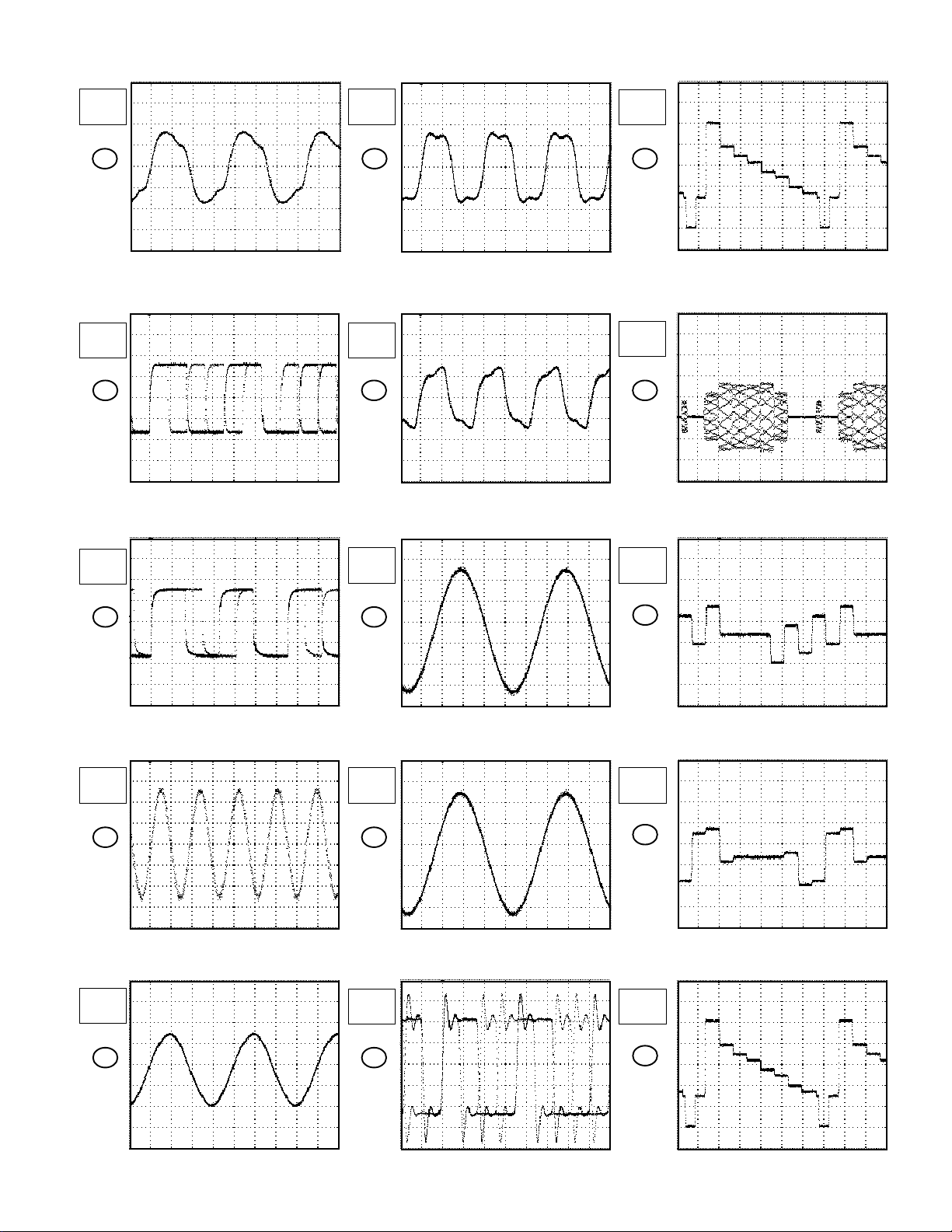
WAVEFORMS
MPEG
10ns
1.0V
1
200ns
1.0V
2
DSP
20ns
1.0V
6
20ns
1.0V
7
10µs
200mV
10µs
200mV
11
12
200ns
1.0V
3
MEMORY
5ns
200mV
4
SYSCON
AUDIO/JACK
200µs
100mV
8
200µs
100mV
9
10µs
200mV
10µs
200mV
13
14
20ns
500mV
200ns
200mV
5
10
H-1
NOTE:
The following waveforms were measured at the point of the
corresponding balloon number in the schematic diagram.
10µs
500mV
15
Page 50

10µs
200mV
16
DISPLAY
1µs
500mV
17
WAVEFORMS
MPEG
10ns
1.0V
18
READ CHANNEL
100ns
200mV
19
100ns
200mV
20
H-2
NOTE:
The following waveforms were measured at the point of the
corresponding balloon number in the schematic diagram.
Page 51
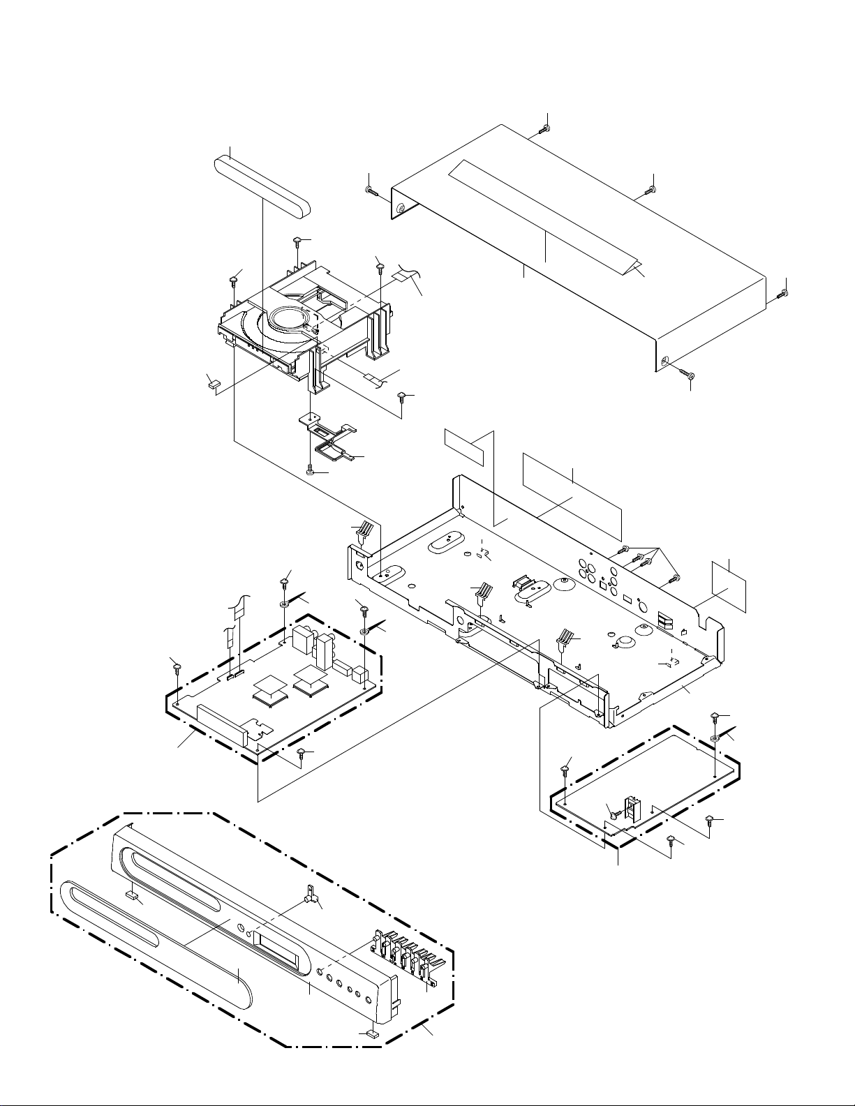
615
MECHANICAL EXPLODED VIEW
703
619
704
704
704
613
705
617
704
703
704
618
CD2601
CD2301
704
617
608
614
703
703
616
703
611
702
610
704
PCB130
(DVD PCB ASS'Y)
608
605
604
704
606
608
613
607
601
617
704
701
PCB020
(POWER PCB ASS'Y)
608
609
704
613
704
704
I1-1
Page 52

PACKING DIAGRAM
INSTRUCTION BOOK
QUICK SET UP SHEET(SPANISH)
REGISTRATION CARD
POLYBAG,INSTRUCTION(RED CAUTION)
TRANSMITTER
ZK02
ZK02
CORD,RCA PIN
GIFT SHEET
ZK02
GIFT BOX
ZK02
I2-1
Page 53

MECHANICAL REPLACEMENT PARTS LIST
Location No. TSB P/N Reference No. Description
601 AD301562 A2B302A720 CABINET,FRONT ASSY
604 AD301563 701WPJ1132 CABINET,FRONT
605 AD301564 711JPB0018 PLATE,DISPLAY
606 AD301565 713WPA0215 GLASS,LED
607 AD301566 735WPB0225 BUTTON,FRAME
608 AD301567 800WFA0051 CUSHION,LEG
609 AD301568 702WSA0131 PLATE,BOTTOM
610 AD301569 7220001161 SHEET,JACK
611 AD301570 7225490088 SHEET,RATING
613 BZ710039 8995034000 CORD CLIP UL CO.
614 AD301571 702WSB0070 CABINET,TOP
615 AD301572 712WPJ0777 PLATE,TRAY-FRONT
616 AD301573 7235490028 POP LABEL
617 AD301574 744WUA0013 SPRING,EARTH
618 BZ710697 761WPA0250 HOLDER,FFC
619 BZ710573 800WFA0045 CUSHION,LEG
701 BZ710239 8109I30A04 SCREW,TAP TITE(B) WH7 3x10
702 BZ710408 8109630604 SCREW,TAP TITE(B) BRAZIER 3x6
703 AD301575 8109K30601 SCREW,TAP TITE(B) BIND(3D) 3x6
704 AD301576 8107D30554 SCREW,TAP TITE(S) R WH8 3x5.5
705 BZ710187 8110226804 SCREW,TAP TITE(P) BIND 2.6x8
--- AD301577 791WHA0100 GIFT SHEET
--- AD301578 792WHA0378 PACKAGE
--- AD301579 793WCD1424 GIFT BOX
--- AD301580 795WCA0661 PAD,DVD/VR
--- AD301581 A2B302A975 INSTRUCTION BOOK KIT
--- AD301582 J2A70617 REGISTRATION CARD
--- AD301583 J2B30201 INSTRUCTION BOOK
--- AD301584 J2B30207 QUICK SET UP SHEET(SPANISH)
J1-1
Page 54

ELECTRICAL REPLACEMENT PARTS LIST
Location No. TSB P/N Reference No. Description
RESISTORS
! R502 AD301531 R3X1811R5J R,METAL OXIDE 1.5 OHM 1W
! R504 BZ210037 R3X181680J R,METAL OXIDE 68 OHM 1W
! R512 AD301018 R002T2104J RC 100K OHM 1/2W
! R531 AD300783 R3X181221J R,METAL OXIDE 220 OHM 1W
CAPACITORS
! C502 BZ110145 P2472B104M CMP 0.1 UF 275V PHE840
! C511 BZ110037 E02AFC820M CE 82 UF 200V
! C513 AD301532 C0JTB0612K CC 100 PF 1KV B
C515 BZ110038 C0JFE0514M CC 0.01 UF 500V E
! C516 AD301391 CD39E0MQ3M CC 0.0047UF 250V or
! C518 BZ110197 E02LU5470M CE 47 UF 50V
! C521 BZ110119 E02LF2222M CE 2200 UF 16V
! C522 AD300511 E02LT0222M CE 2200 UF 6.3V
! C523 BZ210176 E02LF3222M CE 2200 UF 25V
! C526 AD300511 E02LT0222M CE 2200 UF 6.3V
! C527 AD301533 E02LU0331M CE 330 UF 6.3V
! C528 AD301534 E50HU0220M CE 22 UF 6.3V
! C531 AD301535 E02LU2101M CE 100 UF 16V
! C535 AD301536 E02LU2331M CE 330 UF 16V
BZ110196 CB3930MQ3M CC 0.0047UF 250V
DIODES
! D502 BZ410085 D2WXN40050 DIODE,SILICON 1N4005-EIC
! D503 BZ410085 D2WXN40050 DIODE,SILICON 1N4005-EIC
D504 BZ410006 D1VT001330 DIODE,SILICON 1SS133T-77
! D505 BZ410085 D2WXN40050 DIODE,SILICON 1N4005-EIC
! D506 BZ410085 D2WXN40050 DIODE,SILICON 1N4005-EIC
D507 BZ410081 D23TSB0400 DIODE,SILICON SB040-G3
D509 BZ410103 D2WXGP10J0 DIODE,RECTIFIER RGP10J-EIC
! D510 BZ410076 D2WXB290S0 DIODE,SILICON SB290S
! D511 BZ410011 D28TELS2N2 DIODE,RECTIFIER 10ELS2N-TA1B2
! D512 BZ410076 D2WXB290S0 DIODE,SILICON SB290S
! D514 BZ410077 D2WXSB1400 DIODE,SCHOTTKY SB140-EIC
! D516 BZ410011 D28TELS2N2 DIODE,RECTIFIER 10ELS2N-TA1B2
D526 BZ410006 D1VT001330 DIODE,SILICON 1SS133T-77
! D527 BZ410077 D2WXSB1400 DIODE,SCHOTTKY SB140-EIC
! D528 BZ410021 D97U05R61B DIODE,ZENER MTZJ5.6B T-77
D651 BZ410119 DDDRL41480 DIODE,SILICON MCL4148
D652 BZ410119 DDDRL41480 DIODE,SILICON MCL4148
D654 BZ410119 DDDRL41480 DIODE,SILICON MCL4148
D655 BZ410119 DDDRL41480 DIODE,SILICON MCL4148
D656 BZ410119 DDDRL41480 DIODE,SILICON MCL4148
D657 AD301537 0021E5Q210 LED LTL-1CHGE-002A
D658 BZ410081 D23TSB0400 DIODE,SILICON SB040-G3
! D1002 BZ410109 D97U02001B DIODE,ZENER MTZJ20B T-77
! D1003 BZ410090 D97U04R71B DIODE,ZENER MTZJ4.7B T-77
D1005 BZ410119 DDDRL41480 DIODE,SILICON MCL4148
D2601 BZ410120 DDARDS1210 DIODE,SILICON KDS121RTK
D2602 BZ410121 DDARDS1200 DIODE,SILICON KDS120RTK
D7001 BZ410119 DDDRL41480 DIODE,SILICON MCL4148
D7002 BZ410119 DDDRL41480 DIODE,SILICON MCL4148
D7003 BZ410119 DDDRL41480 DIODE,SILICON MCL4148
D7004 BZ410119 DDDRL41480 DIODE,SILICON MCL4148
D7007 BZ410119 DDDRL41480 DIODE,SILICON MCL4148
D7008 BZ410119 DDDRL41480 DIODE,SILICON MCL4148
D7009 BZ410119 DDDRL41480 DIODE,SILICON MCL4148
D7010 BZ410119 DDDRL41480 DIODE,SILICON MCL4148
D7011 BZ410081 D23TSB0400 DIODE,SILICON SB040-G3
D7014 BZ410119 DDDRL41480 DIODE,SILICON MCL4148
D7015 BZ410119 DDDRL41480 DIODE,SILICON MCL4148
D7016 BZ410119 DDDRL41480 DIODE,SILICON MCL4148
D7017 BZ410119 DDDRL41480 DIODE,SILICON MCL4148
D7018 BZ410119 DDDRL41480 DIODE,SILICON MCL4148
D7019 BZ410119 DDDRL41480 DIODE,SILICON MCL4148
ICS
! IC501 BZ611019 I1KJ9A4310 IC KIA431
! IC502 BZ611015 I1KA97805A IC KIA7805API
! IC503 BZ611033 I1KA97809A IC KIA7809API
! IC504 BZ410088 0002E00610 PHOTO COUPLER LTV-817M-VB
IC651 BZ611020 I07F529770 IC BU2977FS
IC1001 BZ611123 ICQF067050 IC ZR36705
IC1002 AD301538 I9UF032290 IC PST3229NR
J2-1
Page 55

ELECTRICAL REPLACEMENT PARTS LIST
Location No. TSB P/N Reference No. Description
ICS
IC1006 BZ611124 I5HJ004BF0 IC S-24C04BFJ-TB
IC2001 BZ611125 I53F086610 IC LC78661W
IC2002 BZ611106 I59J0258B3 IC MSM5416258B-30
IC2301 BZ611126 I03F065600 IC LA6560
IC2601 BZ611127 I07F04066F IC BU4066BCF
IC2602 BZ611128 I03FR97020 IC LA9702WL
IC4001 BZ611110 ICQF067320 IC ZR36732
IC4002 BZ611112 I59J0160FB IC MSM56V16160F-8
IC4005 BZ611129 ICMJ0800A7 IC SST39VF800A-70-4C-EK
IC4006 BZ611130 I0GF9XZ010 IC PQ070XZ01ZP
IC7004 BZ611074 I0QF045800 IC NJM4580M
IC8503 BZ611131 I17F017480 IC PCM1748E
IC8504 BZ611073 I5CF040520 IC SN74LV4052APW
TRANSISTORS
! Q501 BZ510116 TC5U053680 TRANSISTOR,SILICON 2SC5368
! Q502 BZ510031 TD3T007340 TRANSISTOR,SILICON 2SD734(E,F)-AA
Q505 BZ611095 TNATA03002 COMPOUND TRANSISTOR KRC101MAT
Q507 BZ510069 TCATC31980 TRANSISTOR,SILICON KTC3198-AT(Y,GR)
! Q508 BZ510060 TB3T011310 TRANSISTOR,SILICON 2SB1131(S,T)-AE
! Q510 BZ510057 TAAT01281Y TRANSISTOR,SILICON KTA1281_Y
Q512 BZ510069 TCATC31980 TRANSISTOR,SILICON KTC3198-AT(Y,GR)
! Q513 BZ510070 TCAT032034 TRANSISTOR,SILICON KTC3203_Y-AT
Q652 BZ510109 TCAA3875SY TRANSISTOR,SILICON KTC3875S_Y_RTK
Q653 BZ510071 TNAAB05003 COMPOUND TRANSISTOR KRC102SRTK
Q1001 BZ510025 TPYJB05001 COMPOUND TRANSISTOR DTA114EKAT146
Q1002 BZ510021 TNYJC05001 COMPOUND TRANSISTOR DTC124EKAT146
Q1003 BZ510045 TNYJD05001 COMPOUND TRANSISTOR DTC144EKAT146
! Q1004 BZ510070 TCAT032034 TRANSISTOR,SILICON KTC3203_Y-AT
Q2301 BZ510109 TCAA3875SY TRANSISTOR,SILICON KTC3875S_Y_RTK
Q2302 BZ510001 T6YJ1037K0 TRANSISTOR,SILICON 2SA1037AKT146R,S
Q2303 BZ510071 TNAAB05003 COMPOUND TRANSISTOR KRC102SRTK
Q2304 BZ510108 TAAA1504SY TRANSISTOR,SILICON KTA1504S_Y_RTK
Q2601 BZ510109 TCAA3875SY TRANSISTOR,SILICON KTC3875S_Y_RTK
Q2603 BZ510112 T67J1036K0 TRANSISTOR,SILICON 2SA1036KT146
Q2604 BZ510112 T67J1036K0 TRANSISTOR,SILICON 2SA1036KT146
Q2605 BZ510108 TAAA1504SY TRANSISTOR,SILICON KTA1504S_Y_RTK
Q2606 BZ510109 TCAA3875SY TRANSISTOR,SILICON KTC3875S_Y_RTK
Q2607 BZ510113 T27T030180 FET 2SK3018
Q2608 BZ510109 TCAA3875SY TRANSISTOR,SILICON KTC3875S_Y_RTK
Q2609 BZ510109 TCAA3875SY TRANSISTOR,SILICON KTC3875S_Y_RTK
Q2610 BZ510109 TCAA3875SY TRANSISTOR,SILICON KTC3875S_Y_RTK
Q2611 BZ510108 TAAA1504SY TRANSISTOR,SILICON KTA1504S_Y_RTK
Q2612 BZ510113 T27T030180 FET 2SK3018
Q2613 BZ510113 T27T030180 FET 2SK3018
Q2614 BZ510109 TCAA3875SY TRANSISTOR,SILICON KTC3875S_Y_RTK
Q2615 BZ510109 TCAA3875SY TRANSISTOR,SILICON KTC3875S_Y_RTK
Q2616 BZ510109 TCAA3875SY TRANSISTOR,SILICON KTC3875S_Y_RTK
Q7002 BZ510109 TCAA3875SY TRANSISTOR,SILICON KTC3875S_Y_RTK
Q7003 BZ510067 TNAAC05002 COMPOUND TRANSISTOR KRC103SRTK
Q7004 BZ510107 TPAAA05001 COMPOUND TRANSISTOR KRA101SRTK
Q7005 BZ510109 TCAA3875SY TRANSISTOR,SILICON KTC3875S_Y_RTK
Q7006 BZ510109 TCAA3875SY TRANSISTOR,SILICON KTC3875S_Y_RTK
Q7007 BZ510088 TNAAD05001 COMPOUND TRANSISTOR KRC104SRTK
Q7009 BZ510109 TCAA3875SY TRANSISTOR,SILICON KTC3875S_Y_RTK
Q7010 BZ510108 TAAA1504SY TRANSISTOR,SILICON KTA1504S_Y_RTK
COILS & TRANSFORMERS
! L501 BZ310036 029T000083 COIL,LINE FILTER 0R3A433F20
L502 AD301539 02AHB0A0A4 CORE,FERRITE W5T_20*10*10A
L1001 BZ310191 02167F2R2J COIL 2.2 UH
L7001 BZ310192 0216S71R8J COIL 1.8 UH
L7002 BZ310192 0216S71R8J COIL 1.8 UH
L7003 BZ310041 02167F101J COIL 100 UH
L7004 BZ310192 0216S71R8J COIL 1.8 UH
L7005 AD301541 021LA6R27M COIL 0.27 UH
L7006 BZ310192 0216S71R8J COIL 1.8 UH
L7007 AD301541 021LA6R27M COIL 0.27 UH
L7011 BZ310041 02167F101J COIL 100 UH
! T501 AD301542 0481220124 TRANSFORMER,SWITCHING 81220124
JACKS
J7001 AD301543 060J411025 RCA JACK MSP-244V10-44PBSN
J7003 AD301544 060J411026 RCA JACK MSD-243V-18-PBSN
J8001 AD301545 063D700005 JACK MDC-070V
J2-2
Page 56

ELECTRICAL REPLACEMENT PARTS LIST
Location No. TSB P/N Reference No. Description
SWITCHES
SW651 BZ612010 0504101T34 SWITCH,TACT EVQ21505R
SW661 BZ612010 0504101T34 SWITCH,TACT EVQ21505R
SW662 BZ612010 0504101T34 SWITCH,TACT EVQ21505R
SW663 BZ612010 0504101T34 SWITCH,TACT EVQ21505R
SW664 BZ612010 0504101T34 SWITCH,TACT EVQ21505R
SW665 BZ612010 0504101T34 SWITCH,TACT EVQ21505R
SW7001 AD301546 0510Y24001 SWITCH SLIDE SK42H0IG9A
P.C.BOARD ASSEMBLIES
PCB020 AD301547 A2B302A020 PCB ASS'Y VPB158A
PCB130 AD301548 A2B302A130J PCB ASS'Y VMB264A
MISCELLANEOUS
B501 BZ310122 024HT03563 CORE,BEADS W4BRH3.5X6X1.0X2
B1001 BZ310186 024HC31022 CORE,BEADS FCM2012H-102T04
B1002 BZ310186 024HC31022 CORE,BEADS FCM2012H-102T04
B2001 BZ310186 024HC31022 CORE,BEADS FCM2012H-102T04
B2002 BZ310186 024HC31022 CORE,BEADS FCM2012H-102T04
B2003 BZ310186 024HC31022 CORE,BEADS FCM2012H-102T04
B2601 BZ310186 024HC31022 CORE,BEADS FCM2012H-102T04
B2602 BZ310186 024HC31022 CORE,BEADS FCM2012H-102T04
B2604 BZ310186 024HC31022 CORE,BEADS FCM2012H-102T04
B2605 BZ310186 024HC31022 CORE,BEADS FCM2012H-102T04
B2606 BZ310186 024HC31022 CORE,BEADS FCM2012H-102T04
B4001 BZ310186 024HC31022 CORE,BEADS FCM2012H-102T04
B4002 BZ310186 024HC31022 CORE,BEADS FCM2012H-102T04
B4003 BZ310186 024HC31022 CORE,BEADS FCM2012H-102T04
B4004 BZ310186 024HC31022 CORE,BEADS FCM2012H-102T04
B7001 BZ310186 024HC31022 CORE,BEADS FCM2012H-102T04
B7011 BZ310186 024HC31022 CORE,BEADS FCM2012H-102T04
B8501 BZ310186 024HC31022 CORE,BEADS FCM2012H-102T04
B8502 BZ310186 024HC31022 CORE,BEADS FCM2012H-102T04
! CD501 AD301549 120R419905 CORD,AC BUSH 0R419905
CD502 AD301550 06CU2C2501 CORD,CONNECTOR CU2C2501
CD503 AD301551 WHL6008038 FLAT CABLE AWM2468 A WG26 10C BLACK 80MM
CD601 AD301552 06CQBA2001 CORD,RCA PIN SI-B-701-2
CP503 BZ614273 067U010049 WIRE HOLDER B2013H02-10P
CP661 BZ614058 069W010010 CONNECTOR PCB SIDE 005P-2100
CD2301 BZ614435 122H081007 CORD,JUMPER 2H081007
CD2302 BZ614436 06CU251002 CORD,CONNECTOR CU251002
CD2601 AD301553 122H0O2303 CORD,JUMPER 2H0O2303
CP1002 AD301554 069S2C0629 CONNECTOR PCB SIDE A2001WV2-12P
CP1003 BZ614274 069R2A0589 CONNECTOR PCB SIDE 52147-1010
CP2301 AD301555 069EV83010 CONNECTOR PCB SIDE 00_6232_008_006_800
CP2302 AD300752 069S250629 CONNECTOR PCB SIDE A2001WV2-5P
CP2601 AD301556 069XYOT049 CONNECTOR PCB SIDE 24FLT-SM1-TB
! DK4001 AD301557 169G00016A DECK CD DVD-KDR777SK
! F501 BZ614351 081PC1R605 FUSE 51MS016L
FH501 BZ614005 06710T0006 HOLDER,FUSE EYF-52BC
FH502 BZ614005 06710T0006 HOLDER,FUSE EYF-52BC
! ICP502 AD301558 0835C03003 MICRO FUSE 20N_3000FS
OS651 BZ614352 077Q037001 REMOTE RECEIVER PIC-37043LO
OS7001 AD301559 07A9000004 OPTICAL DEVICE GP1FA550TZ
TM601 AD301560 076D0FS010 TRANSMITTER ORV202N19010
V651 AD301561 097X69R001 TUBE FLUORESCENT DISPLAY HNV-06SS71
X1001 BZ613020 100CT01210 CRYSTAL HC-49/U
X2001 BZ613038 100CT01604 CRYSTAL HC-49/U-S
X4001 BZ613035 100WT02706 CRYSTAL HC-49/U-S
RESISTOR
CAPACITORS
RC................... CARBON RESISTOR
CC................... CERAMIC CAPACITOR
CE................... ALUMI ELECTROLYTIC CAPACITOR
CP................... POLYESTER CAPACITOR
CPP.................. POLYPROPYLENE CAPACITOR
CPL.................. PLASTIC CAPACITOR
CMP....................... METAL POLYESTER CAPACITOR
CMPL................ METAL PLASTIC CAPACITOR
CMPP................ METAL POLYPROPYLENE CAPACITOR
J2-3
Page 57

TOSHIBA CORPORATION
1-1, SHIBAURA 1-CHOME, MINATO-KU, TOKYO 105-8001, JAPAN
 Loading...