

Page 1

SERVICE MANUAL
AIR-CONDITIONER
SPLIT TYPE
INDOOR UNIT
FILE NO. SVM-12004
High Wall Type
RAV-SM566KRT-E, RAV-SM806KRT-E
RAV-SM566KRT-TR, RAV-SM806KRT-TR
R410A
Page 2

FILE NO. SVM-12004
Adoption of New Refrigerant
This Air Conditioner is a new type which adopts a new refrigerant HFC (R410A) instead of the conventional
refrigerant R22 in order to prevent destruction of the ozone layer.
CONTENTS
SAFETY CAUTION ............................................................................................ 3
1. SPECIFICATIONS .................................................................................... 12
1-1. High Wall Type ................................................................................................................. 12
2. CONSTRUCTION VIEWS (EXTERNAL VIEWS)....................................... 13
3. SYSTEMATIC REFRIGERATING CYCLE DIAGRAM .............................. 15
4. WIRING DIAGRAM ................................................................................... 16
5. SPECIFICATIONS OF ELECTRICAL PARTS .......................................... 17
6. REFRIGERANT R410A ............................................................................ 18
6-1. Safety During Installation/Servicing............................................................................. 18
6-2. Refrigerant Piping Installation .................................................................................... 18
6-3. Tools ................................................................................................................................ 22
6-4. Recharging of Refrigerant ............................................................................................. 23
6-5. Brazing of Pipes ............................................................................................................. 24
7. INDOOR CONTROL CIRCUIT.................................................................. 26
7-1. Indoor Controller Block Diagram ................................................................................. 26
7-2. Control Specifications .................................................................................................. 28
7-3. Indoor Print Circuit Board (High Wall Type) ................................................................. 40
8. TROUBLESHOOTING .............................................................................. 42
8-1. Summary of Troubleshooting ....................................................................................... 42
8-2. Troubleshooting ............................................................................................................ 44
9. REPLACEMENT OF SERVICE P.C. BOARD............................................ 60
10. SETUP AT LOCAL SITE AND OTHERS .................................................. 66
11. ADDRESS SETUP.................................................................................... 83
11-1. Address Setup Procedure ............................................................................................. 83
11-2. Address Setup & Group/Twin/Triple Control ............................................................... 84
11-3. Address Setting ............................................................................................................. 86
12. DETACHMENTS ....................................................................................... 88
13. EXPLODED VIEWS AND PARTS LIST .................................................... 95
14. APPENDIX (Lite-vision plus remote controller Installation manual) ..... 97
– 2 –
Page 3
Original instruction
FILE NO. SVM-12004
Please read carefully through these instructions that contain important information which complies with the
“Machinery” Directive (Directive 2006/42/EC), and ensure that you understand th em.
Generic Denomination: Air Conditioner
Definition of Qualified Installer or Qualified Service Person
The air conditioner must be installed, maintained, repaired a nd removed by a qualified installer or qualified service
person. When any of these jobs is to be done, ask a qualified installer or qualified service pe rson to do them for you.
A qualified installer or qualified service person is an agent who has the qualification s and kno wledge descr ibed in
the table below.
Agent Qualifications and knowledge which the agent must have
• The qualified installer is a person who installs, maintains, relocates and removes the air conditioners
made by Toshiba Carrier Corporation. He or she has been trained to install, maintain, relocate and
remove the air conditioners made by Toshiba Carrier Corporation or, alternatively, he or she has been
instructed in such operations by an individual or individuals who have been trained and is thus
thoroughly acquainted with the knowledge related to these operations.
• The qualified installer who is allowed to do the electrical work involved in installation, relocation and
removal has the qualifications pertaining to this electrical work as stipulated by the local laws and
regulations, and he or she is a person who has been trained in matters relating to electrical work on
the air conditioners made by Toshiba Carrier Corporation or, alternatively, he or she has been
instructed in such matters by an individual or individuals who have been trained and is thus thoroughly
Qualified installer
Qualified service
person
acquainted with the knowledge related to this work.
• The qualified installer who is allowed to do the refrigerant handling and piping work involved in
installation, relocation and removal has the qualifications pertaining to this refrigerant handling and
piping work as stipulated by the local laws and regulations, and he or she is a person who has been
trained in matters relating to refrigerant handling and piping work on the air conditioners made by
Toshiba Carrier Corporation or, alternatively, he or she has been instructed in such matters by an
individual or individuals who have been trained and is thus thoroughly acquainted with the knowledge
related to this work.
• The qualified installer who is allowed to work at heights has been trained in matters relating to working
at heights with the air conditioners made by Toshiba Carrier Corporation or, alternatively, he or she
has been instructed in such matters by an individual or individuals who have been trained and is thus
thoroughly acquainted with the knowledge related to this work.
• The qualified service person is a person who installs, repairs, maintains, relocates and removes the
air conditioners made by Toshiba Carrier Corporation. He or she has been traine d to install, repair,
maintain, relocate and remove the air conditioners made by Toshiba Carrier Corporation or,
alternatively, he or she has been instructed in such operations by an individual or individuals who have
been trained and is thus thoroughly acquainted with the knowledge related to these operations.
• The qualified service person who is allowed to do the electrical work involved in installation, repair,
relocation and removal has the qualifications pertaining to this electrical work as stipulated by the local
laws and regulations, and he or she is a person who has been trained in matters relating to electrical
work on the air conditioners made by Toshiba Carrier Corporation or, alternatively, he or she has been
instructed in such matters by an individual or individuals who have been trained and is thus thoroughly
acquainted with the knowledge related to this work.
• The qualified service person who is allowed to do the refrigerant handling and piping work involved in
installation, repair, relocation and removal has the qualifications pertaining to this refrigerant handling
and piping work as stipulated by the local laws and regulations, and he or she is a person who has
been trained in matters relating to refrigerant handling and piping work on the air conditioners made
by Toshiba Carrier Corporation or, alternatively, he or she has been instructed in such matters by an
individual or individuals who have been trained and is thus thoroughly acquainted with the knowledge
related to this work.
• The qualified service person who is allowed to work at heights has been trained in matters relating to
working at heights with the air conditioners made by Toshiba Carrier Corporation or, alternatively, he
or she has been instructed in such matters by an individual or individuals who have been trained and
is thus thoroughly acquainted with the knowledge related to this work.
– 3 –
Page 4
FILE NO. SVM-12004
Definition of Protective Gear
When the air conditioner is to be transported, installed, maintained, repaired or removed, wear protective gloves
and ‘safety’ work clothing.
In addition to such normal protective gear, wear the protective gear described bel ow when undertaking the special
work detailed in the table below.
Failure to wear the proper protective gear is dangerous because you will be more susceptible to injury, burns,
electric shocks and other injuries.
Work undertaken Protective gear worn
All types of work
Electrical-related work
Work done at heights
(50 cm or more)
Transportation of heavy objects Shoes with additional protective toe cap
Repair of outdoor unit Gloves to provide protection for electricians and from heat
The important contents concerned to the safety are described on the product itself and on this Service Manual.
Please read this Service Manual after understanding the described items thoroughly in the following contents
(Indications / Illustrated marks), and keep the m .
Protective gloves
‘Safety’ working clothing
Gloves to provide protection for electricians and from heat
Insulating shoes
Clothing to provide protection from electric shock
Helmets for use in industry
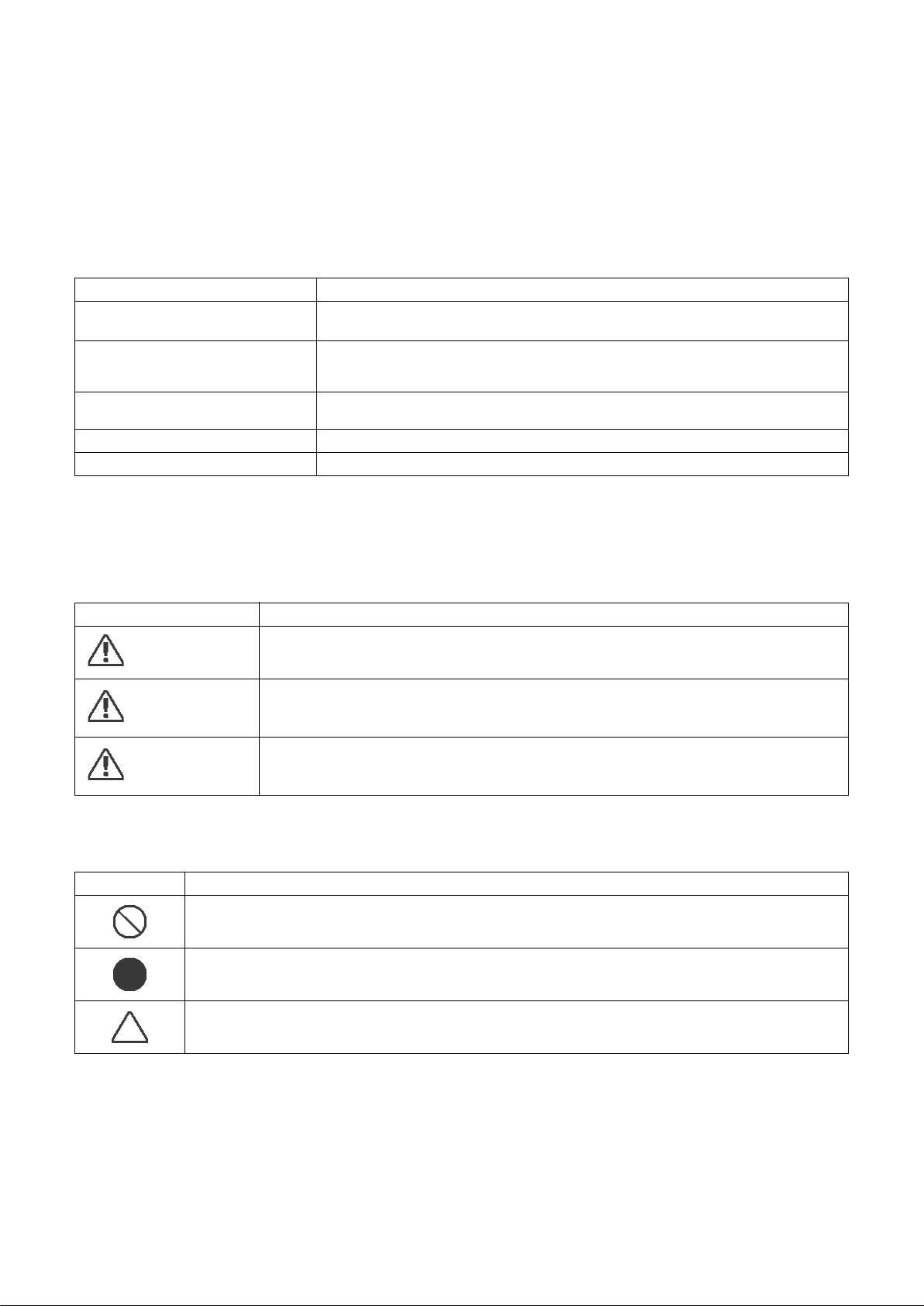
[Explanation of indications]
Indication Explanation
DANGER
WARNING
CAUTION
Indicates contents assumed that an imminent danger causing a death or serious injury of
the repair engineers and the third parties when an incorrect work has been executed.
Indicates possibilities assumed that a danger causing a death or serious injury of the
repair engineers, the third parties, and the users due to troubles of the product after work
when an incorrect work has been executed.
Indicates contents assumed that an injury or property damage (*) may be caused on the
repair engineers, the third parties, and the users due to troubles of the product after work
when an incorrect work has been executed.
* Property damage: Enlarged damage concerned to property, furniture, and domestic animal / pet
[Explanation of illustrated marks]
Mark Explanation
Indicates prohibited items (Forbidden items to do)
The sentences near an illustrated mark describe the concrete prohibited contents.
Indicates mandatory items (Compulsory items to do)
The sentences near an illustrated mark describe the concrete mandatory contents.
Indicates cautions (Including danger / warning)
The sentences or illustration near or in an illustrated mark describe the concrete cautious contents.
– 4 –
Page 5
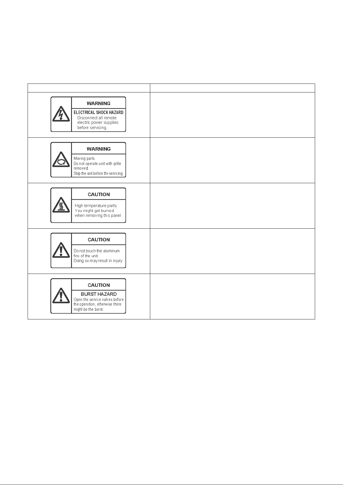
Warning Indications on the Air Conditioner Unit
[Confirmation of warning label on the main unit]
Confirm that labels are indicated on the specified positions
If removing the label during parts replace, stick it as the original.
Warning indication Description
WARNING
ELECTRICAL SHOCK HAZARD
Disconnect all remote electric power supplies before servicing.
WARNING
Moving parts.
Do not operate unit with grille removed.
Stop the unit before the servicing.
FILE NO. SVM-12004
CAUTION
High temperature parts.
You might get burned when removing this panel.
CAUTION
Do not touch the aluminium fins of the unit.
Doing so may result in injury.
CAUTION
BURST HAZARD
Open the service valves before the operation, otherwise t here might be the
burst.
– 5 –
Page 6
FILE NO. SVM-12004
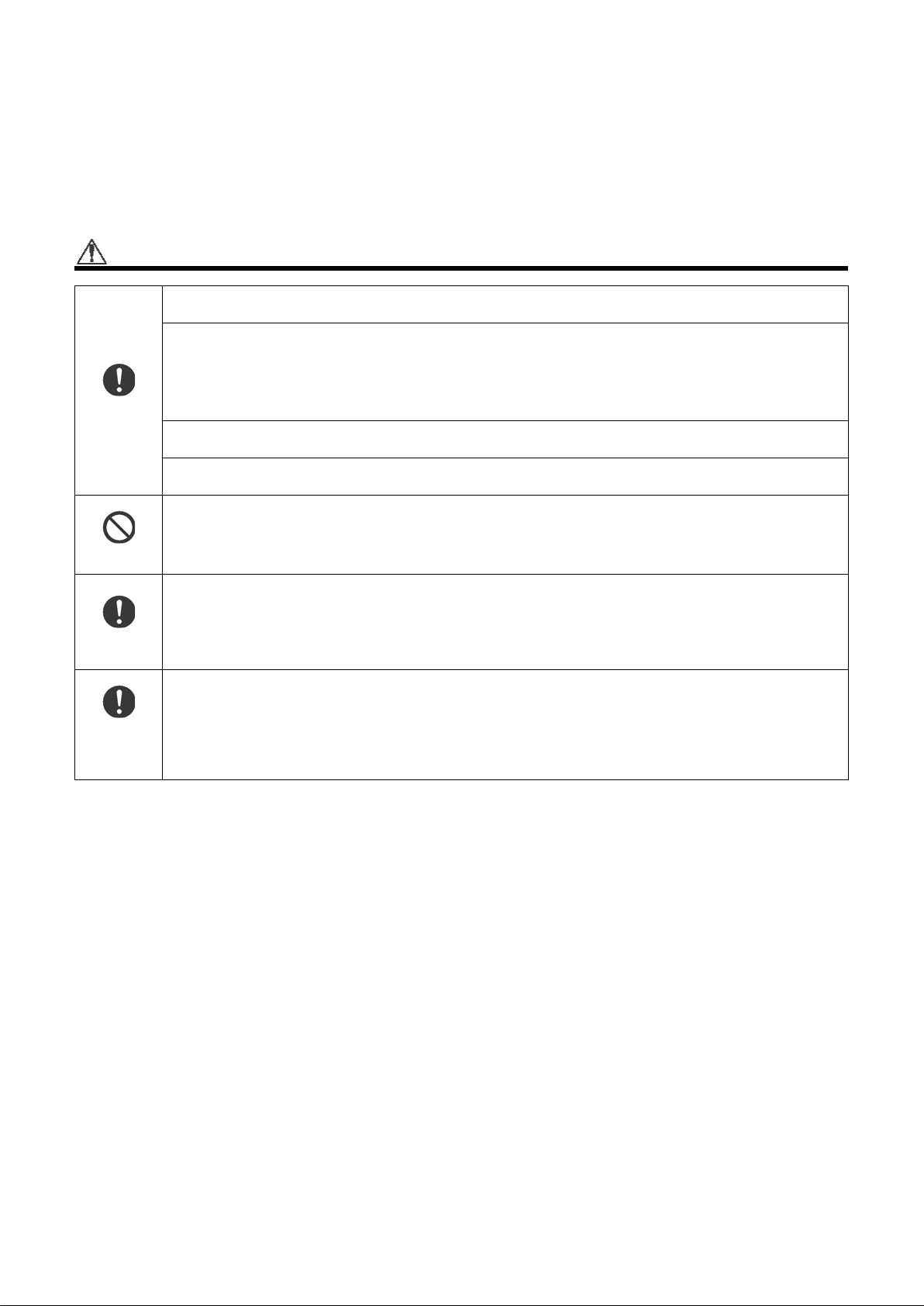
Precautions for safety
The manufacturer shall not assume any liability for the damage caused by not observing the description of this
manual.
DANGER
Before carrying out the installation, maintenance, repair or removal work, be sure to set the circuit breaker for
both the indoor and outdoor units to the OFF position. Otherwise, electric shocks may result.
Before opening the front panel of the indoor unit or service panel of the outdoor unit, set the circuit breaker to
the OFF position.
Failure to set the circuit breaker to the OFF position may result in electric shocks through contact with the interior
parts.
Only a qualified installer (*1) or qualified service person (*1) is allowed to remove the front panel of the indoor
Turn off
breaker.
unit or service panel of the outdoor unit and do the work required.
Before starting to repair the outdoor unit fan or fan guard, be absolutely sure to set the circuit breaker to the
OFF position, and place a “Work in progress” sign on the circuit breaker.
When cleaning the filter or other parts of the indoor unit, set the circuit breaker to OFF without fail, and place a
“Work in progress” sign near the circuit breaker before proceeding with the work.
Prohibition
Stay on
protection
Execute
discharge
between
terminals.
Place a “Work in progress” sign near the circuit breaker while the installation, maintenance, repair or removal
work is being carried out.
There is a danger of electric shocks if the circuit breaker is set to ON by mistake.
If, in the course of carrying out repairs, it becomes absolutely necessary to check out the electrical parts with
the electrical control box cover of one or more of the indoor units and the service panel of the outdoor unit
removed in order to find out exactly where the trouble lies, wear insulated heat-resistant gloves, insulated boots
and insulated work overalls, and take care to avoid touching any live parts.
You may receive an electric shock if you fail to heed this warning. Only qualified service person (*1) is allowed
to do this kind of work.
Even if the circuit breaker has been set to the OFF position before the service panel is removed and the
electrical parts are repaired, you will still risk receiving an electric shock.
For this reason, short-circuit the high-voltage capacitor terminals to discharge the voltage before proceeding
with the repair work.
For details on the short-circuiting procedure, refer to the Service Manual.
You may receive an electric shock if the voltage stored in the capacitors has not been sufficiently discharged.
– 6 –
Page 7
WARNING
General
FILE NO. SVM-12004
Before starting to repair the air conditioner, read carefully through the Service Manual, and repair the air
conditioner by following its instructions.
Only qualified service person (*1) is allowed to repair the air conditioner.
Repair of the air conditioner by unqualified person may give rise to a fire, electric shocks, injury, water leaks
and/or other problems.
Do not use any refrigerant different from the one specified for complement or replacement.
Otherwise, abnormally high pressure may be generated in the refrigeration cycle, which may result in a failure
or explosion of the product or an injury to your body.
Only a qualified installer (*1) or qualified service person (*1) is allowed to carry out the electrical work of the air
conditioner.
Under no circumstances must this work be done by an unqualified individual since failure to carry out the work
properly may result in electric shocks and/or electrical leaks.
When transporting the air conditioner, wear shoes with protective toe caps, protective gloves and other
protective clothing.
Inside the air conditioner are high-voltage areas and rotating parts. Due to the danger of electric shocks or of
your fingers or physical objects becoming trapped in the rotating parts, do not remove the front panel of the
indoor unit or service panel of the outdoor unit. When work involving the removal of these parts is required,
contact a qualified installer(*1) or a qualified service person(*1).
When connecting the electrical wires, repairing the electrical parts or undertaking other electrical jobs, wear
gloves to provide protection for electricians and from heat, insulating shoes and clothing to provide protection
from electric shocks.
Failure to wear this protective gear may result in electric shocks.
When checking the electrical parts, removing the cover of the electrical control box of Indoor Unit and/or service
panel of Outdoor Unit inevitably to determine the failure, use gloves to provide protection for electricians and
from heat, insulating shoes, clothing to provide protection from electric shock and insulating tools. Do not touch
the live part. Electric shock may result. Only "Qualified service person (*1)" is allowed to do this work.
When checking the electrical parts, removing the cover of the electrical control box of Indoor Unit and/or front
panel of Outdoor Unit inevitably to determine the failure, put a sign "Do not enter" aro und the site before the
work. Failure to do this may result in third person getting electric shock.
Electrical wiring work shall be conducted according to law and regulation in the community and installation
manual. Failure to do so may result in electrocution or short circuit.
Only a qualified installer (*1) or qualified service person (*1) is allowed to undertake work at heights using a
stand of 50 cm or more or to remove the front panel of the indoor unit to undertake work.
When working at heights, use a ladder which complies with the ISO 14122 standard, and follow the procedure
in the ladder’s instructions.
Also wear a helmet for use in industry as protective gear to undertake the work.
When working at heights, put a sign in place so that no-one will approach the work location, before proceeding
with the work.
Parts and other objects may fall from above, possibly injuring a person below.
While carrying out the work, wear a helmet for protection from falling objects.
Wear protective gloves and safety work clothing during installation, servicing and removal.
Do not touch the aluminum fin of the outdoor unit.
You may injure yourself if you do so. If the fin must be touched for some reason, first put on protective gloves
and safety work clothing, and then proceed.
Do not climb onto or place objects on top of the outdoor unit.
You may fall or the objects may fall off of the outdoor unit and resul t in injury.
When transporting the air conditioner, wear shoes with additional protective toe caps.
When transporting the air conditioner, do not take hold of the bands around the packing carton.
You may injure yourself if the bands should break.
Use wiring that meets the specifications in the Installation Manual and the stipulations in the local regulations
and laws. Use of wiring which does not meet the specifications may give rise to electric shocks, electrical
leakage, smoking and/or a fire.
This air conditioner has passed the pressure test as specified in IEC 60335-2-40 Annex EE.
– 7 –
Page 8
Check earth
wires.
Prohibition of
modification.
Use specified
parts.
Do not bring a
child close to
the
equipment.
FILE NO. SVM-12004
Before troubleshooting or repair work, check the earth wire is connected to the earth terminals of the main unit,
otherwise an electric shock is caused when a leak occurs.If the earth wire is not correctly connected, contact
an electric engineer for rework.
After completing the repair or relocation work, check that the ground wires are connected properly.
Be sure to connect earth wire. (Grounding work) Incomplete grounding causes an electric shock.
Do not connect ground wires to gas pipes, water pipes, and lightning rods or ground wires for telephone wires.
Do not modify the products.Do not also disassemble or modify the parts.
It may cause a fire, electric shock or injury.
When any of the electrical parts are to be replaced, ensure that the replacement parts satisfy the specifications
given in the Service Manual (or use the parts contained on the parts list in the Service Manual).
Use of any parts which do not satisfy the required specifications may give rise to electric shocks, smoking and/
or a fire.
If, in the course of carrying out repairs, it becomes absolutely necessary to check out the electrical parts with
the electrical control box cover of one or more of the indoor units and the service panel of the outdoor unit
removed in order to find out exactly where the trouble lies, put a sign in place so that no-one will approach the
work location before proceeding with the work. Third-party individuals may enter the work site and receive
electric shocks if this warning is not heeded.
Insulating
measures
No fire
Refrigerant
Connect the cut-off lead wires with crimp contact, etc., put the closed end side upward and then apply a watercut method, otherwise a leak or production of fire is caused at the users’ side.
When performing repairs using a gas burner, replace the refrigerant with nitrogen gas because the oil that coats
the pipes may otherwise burn.
When repairing the refrigerating cycle, take the following measures.
1) Be attentive to fire around the cycle. When using a gas stove, etc., be sure to put out fire before work;
otherwise the oil mixed with refrigerant gas may catch fire.
2) Do not use a welder in the closed room. When using it without ventilation, carbon monoxide poisoning may
be caused.
3) Do not bring inflammables close to the refrigerant cycle, otherwise fire of the welder may catch the
inflammables.
The refrigerant used by this air conditioner is the R410A.
Check the used refrigerant name and use tools and materials of the parts which match with it.
For the products which use R410A refrigerant, the refrigerant name is indicated at a position on the outdoor unit
where is easy to see. To prevent miss-charging, the route of the service port is changed from one of the former
R22.
For an air conditioner which uses R410A, never use other refrigerant than R410A. For an air conditioner which
uses other refrigerant (R22, etc.), never use R410A.
If different types of refrigerant are mixed, abnormal high pressure generates in the refrigerating cycle and an
injury due to breakage may be caused.
Do not charge refrigerant additionally. If charging refrigerant additionally when refrigerant gas leaks, the
refrigerant composition in the refrigerating cycle changes resulted in change of air conditioner characteristics or
refrigerant over the specified standard amount is charged and an abnormal high pressure is applied to the inside
of the refrigerating cycle resulted in cause of breakage or injury. Therefore if the refrigerant gas leaks, recover
the refrigerant in the air conditioner, execute vacuuming, and then newly recharge the specified amount of liquid
refrigerant.
In this time, never charge the refrigerant over the specified amount.
When recharging the refrigerant in the refrigerating cycle, do not mix the refrigerant or air other than R410A into
the specified refrigerant. If air or others is mixed with the refrigerant, abnormal hig h pressure generates in the
refrigerating cycle resulted in cause of injury due to breakage.
After installation work, check the refrigerant gas does not leak. If the refrigerant gas leaks in the room,
poisonous gas generates when gas touches to fire such as fan heater, stove or cocking stove though the
refrigerant gas itself is innocuous.
Never recover the refrigerant into the outdoor unit. When the equipment is moved or repaired, be sure to recover
the refrigerant with recovering device.
The refrigerant cannot be recovered in the outdoor unit; otherwise a serious accident such as breakage or injury
is caused.
– 8 –
Page 9
Assembly /
Wiring
Insulator
check
Ventilation
Compulsion
Check after
repair
FILE NO. SVM-12004
After repair work, surely assemble the disassembled parts, and connect and lead the removed wires as before.
Perform the work so that the cabinet or panel does not catch the inner wires.
If incorrect assembly or incorrect wire connection was done, a disaster such as a leak or fire is caused at user’s
side.
After the work has finished, be sure to use an insulation tester set (500 V Megger) to check the resistance is
1 MΩ or more between the charge section and the non-charge metal section (Earth position).
If the resistance value is low, a disaster such as a leak or electric shock is caused at user’s side.
If refrigerant gas has leaked during the installation work, ventilate the room immediately. If the leaked refrigerant
gas comes in contact with fire, noxious gas may generate.
When the refrigerant gas leaks, find up the leaked position and repair it surely.
If the leaked position cannot be found up and the repair work is interrupted, pump-down and tighten the service
valve, otherwise the refrigerant gas may leak into the room.
The poisonous gas generates when gas touches to fire such as fan heater, stove or cocking stove though the
refrigerant gas itself is innocuous.
When installing equipment which includes a large amount of charged refrigerant such as a multi air conditioner
in a sub-room, it is necessary that the density does not the limit even if the refrigerant leaks.
If the refrigerant leaks and exceeds the limit density, an accident of shortage of oxygen is caused.
Tighten the flare nut with a torque wrench in the specified manner.
Excessive tighten of the flare nut may cause a crack in the flare nut after a long period, which may result in
refrigerant leakage.
Nitrogen gas must be used for the airtight test.
The charge hose must be connected in such a way that it is not slack.
For the installation / moving / reinstallation work, follow to the Installation Manual.
If an incorrect installation is done, a trouble of the refrigerating cycle, water leak, electric shock or fire is caused.
Before operating the air conditioner after having completed the work, check that the electrical control box cover
of the indoor unit and service panel of the outdoor unit are closed, and set the circuit breaker to the ON position.
You may receive an electric shock if the power is turned on without first conducting these checks.
Once the repair work has been completed, check for refrigerant leaks, and check the insulation resistance and
water drainage.
Then perform a trial run to check that the air conditioner is running properly.
After repair work has finished, check t here i s no trou ble. If check is not executed, a fire, electric shock or injury
may be caused. For a check, turn off the power breaker.
After repair work (installation of front panel and cabinet) has finished, execute a test run to check there is no
generation of smoke or abnormal sound.
If check is not executed, a fire or an electric shock is caused. Before test run, install the front panel and cabinet.
Be sure to fix the screws back which have been removed for installation or other purposes.
Do not
operate the
unit with the
valve closed.
Check after
reinstallation
Check the following matters before a test run after repairing piping.
• Connect the pipes surely and there is no leak of refrigerant.
• The valve is opened.
Running the compressor under condition that the valve closes causes an abnormal high pressure resulted in
damage of the parts of the compressor and etc. and moreover if there is leak of refrigerant at connecting section
of pipes, the air is sucked and causes further abnormal high pressure resulted in burst or injury.
Only a qualified installer (*1) or qualified service person (*1) is allowed to relocate the air conditioner. It is
dangerous for the air conditioner to be relocated by an unqualified individual since a fire, electric shocks, injury,
water leakage, noise and/or vibration may result.
Check the following items after reinstallation.
1) The earth wire is correctly connected.
2) The power cord is not caught in the product.
3) There is no inclination or unsteadiness and the installation is stable.
If check is not executed, a fire, an electric shock or an injury is caused.
When carrying out the pump-down work shut down the compressor before disconnecting the refrigerant pipe.
Disconnecting the refrigerant pipe with the service valve left open and the compressor still operating will cause
air, etc. to be sucked in, raising the pressure inside the refrigeration cycle to an abnormally high level, and
possibly resulting in reputing, injury, etc.
– 9 –
Page 10
Cooling check
Installation
FILE NO. SVM-12004
When the service panel of the outdoor unit is to be opened in order for the compressor or the area around this
part to be repaired immediately after the air conditioner has been shut down, set the circuit breaker to the OFF
position, and then wait at least 10 minutes before opening the service panel.
If you fail to heed this warning, you will run the risk of burning yourself because the compressor pipes and other
parts will be very hot to the touch. In addition, before proceeding with the repair work, wear the kind of insulated
heat-resistant gloves designed to protect electricians.
When the service panel of the outdoor unit is to be opened in order for the fan motor, reactor, inverter or the
areas around these parts to be repaired immediately after the air conditioner has been shut down, set the circuit
breaker to the OFF position, and then wait at least 10 minutes before opening the service panel.
If you fail to heed this warning, you will run the risk of burning yourself because the fan motor, reactor, inverter
heat sink and other parts will be very hot to the touch.
In addition, before proceeding with the repair work, wear the kind of insulated heat-resistant gloves designed to
protect electricians.
Only a qualified installer (*1) or qualified service person (*1) is allowed to install the air conditioner. If the air
conditioner is installed by an unqualified individual, a fire, electric shocks, injury, water leakage, noise and/or
vibration may result.
Before starting to install the air conditioner, read carefully through the Installation Manual , and follow its
instructions to install the air conditioner.
Do not install the air conditioner in a location that may be subject to a risk of expire to a combustible gas.
If a combustible gas leaks and becomes concentrated around the unit, a fire may occur.
Install the indoor unit at least 2.0 m above the floor level since otherwise the users may injure themselves or
receive electric shocks if they poke their fingers or other objects into the indoor unit while the air conditioner is
running.
Install a circuit breaker that meets the specifications in the installation manual and the stipulations in the local
regulations and laws.
Install the circuit breaker where it can be easily accessed by the qualified service person (*1).
If the unit is installed in a small room, take appropriate measures to prevent the refrigerant from exceeding the
limit concentration even if it leaks. Consult the dealer from whom you purchased the air conditioner when you
implement the measures. Accumulation of highly concentrated refrigerant may cause an oxygen deficiency
accident.
Do not place any combustion appliance in a place where it is directly exposed to the wind of air conditioner,
otherwise it may cause imperfect combustion.
Explanations given to user
If you have discovered that the fan grille is damaged, do not approach the outdoor unit but set the circuit breaker
to the OFF position, and contact a qualified service person to have the repairs done .
Do not set the circuit breaker to the ON position until the repairs are completed.
Relocation
• Only a qualified installer (*1) or qualified service person (*1) is allowed to relocate the air conditioner.
It is dangerous for the air conditioner to be relocated by an unqualified individual since a fire, electric shocks,
injury, water leakage, noise and/or vibration may result.
• When carr ying ou t the pum p-d own work shut down the compressor before disconnecting the refrigerant pipe.
Disconnecting the refrigerant pipe with the service valve left open and the compressor still operating will cause
air, etc. to be sucked in, raising the pressure inside the refrigeration cycle to an abnormally high level, and
possibly resulting in reputing, injury, etc.
(*1) Refer to the “Definition of Qualified Installer or Qualified Service Person”
– 10 –
Page 11

Declaration of Conformity
FILE NO. SVM-12004
Manufacturer: TOSHIBA CARRIER (THAILAND) CO., LTD.
Authorized Nick Ball
Representative / TCF holder: Toshiba EMEA Engineering Director
Hereby declares that the machinery described below:
Generic Denomination: Air Conditioner
Model / type: RAV-SM566KRT-E, RAV-SM806KRT-E
Commercial name: Digital Inverter Series / Super Digital Inverter Series Air Conditioner
Complies with the provisions of the “Machinery” Directive (Directive 2006/42/EC) and the regulations transposing into national law.
Complies with the provisions of the following harmonized standard:
144/9 Moo 5, Bangkadi Industrial Park, Tivanon Road,
Amphur Muang, Pathumthani 12000, Thailand
Toshiba Carrier UK Ltd.
Porsham Close, Belliver Industrial Estate,
PLYMOUTH, Devon, PL6 7DB.
United Kingdom
RAV-SM566KRT-TR, RAV-SM806KRT-TR
EN 378-2: 2008 + A1: 2009
NOTE
This declaration becomes invalid if technical or operational modifications are introduced without the manufacturer ’s
consent.
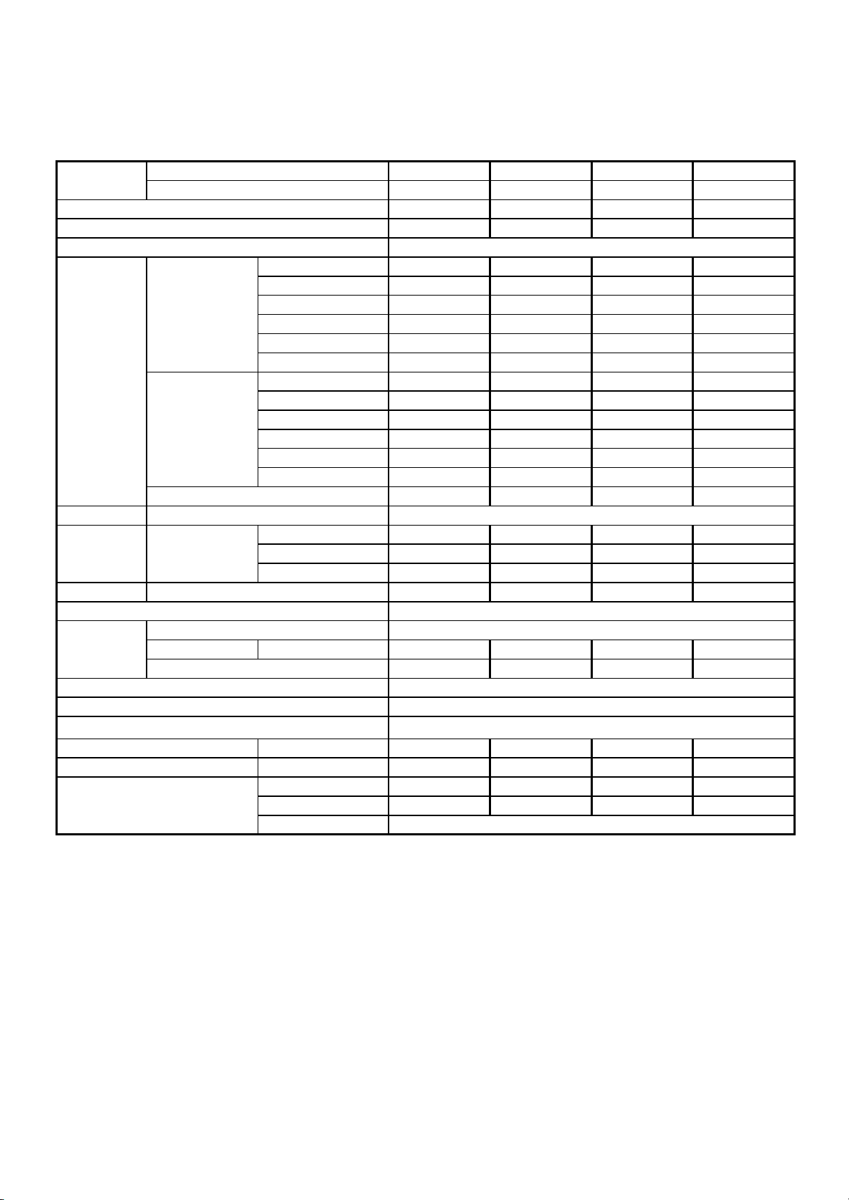
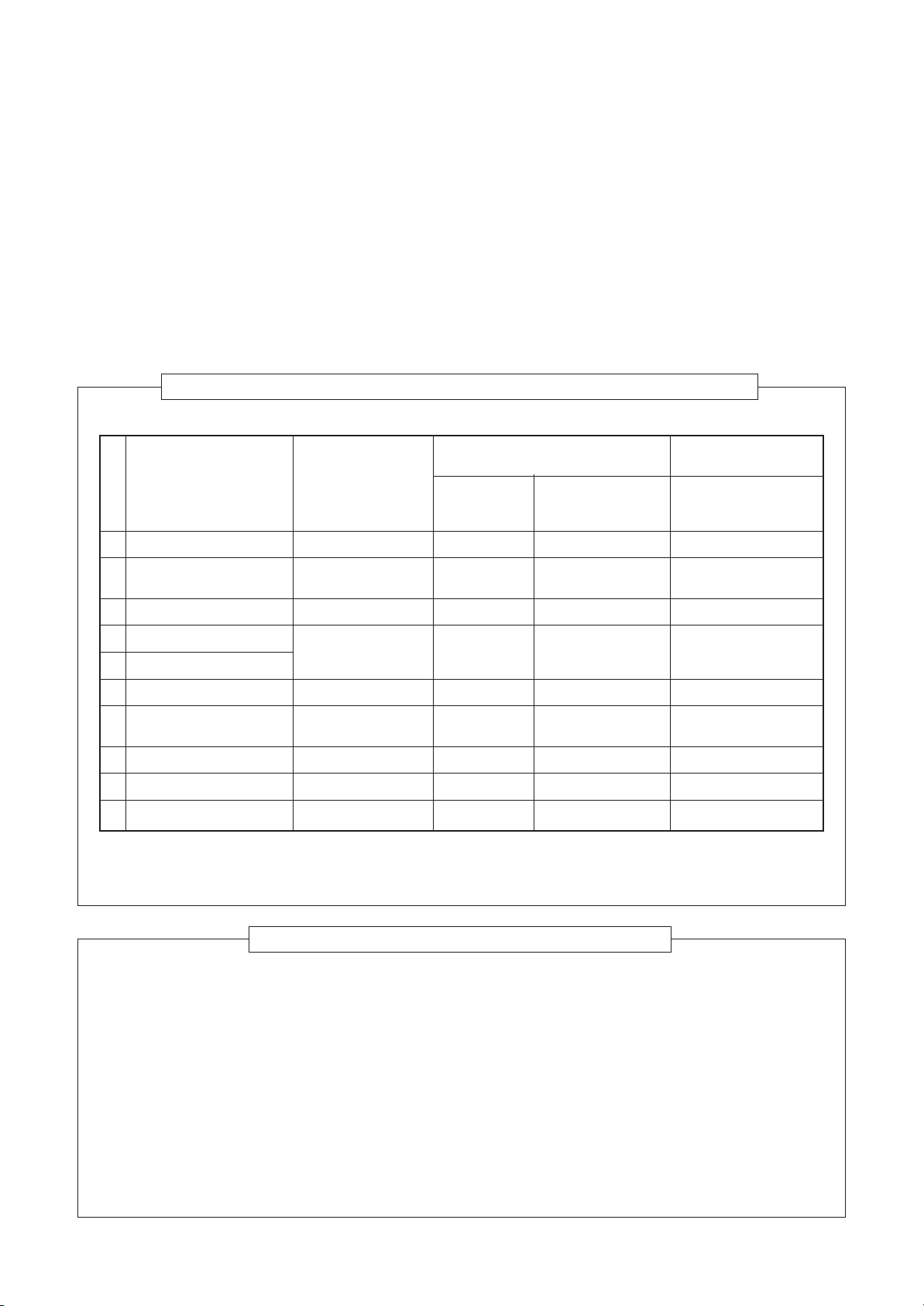
Specifications
Model
RAV-SM566KRT-E ✽✽ 12
RAV-SM806KRT-E ✽✽ 12
RAV-SM566KRT-TR ✽✽ 12
RAV-SM806KRT-TR ✽✽ 12
✽ Under 70 dBA
Sound power level (dBA) Weight (kg)
Cooling Heating Main unit (Ceiling panel)
– 11 –
Page 12
1-1. High-wall type
FILE NO. SVM-12004
1. SPECIFICATIONS
Model
Indoor unit RAV-SM
Outdoor unit RAVCooling Capacity (kW)
Heating Capacity (kW)
Power Supply
Running current (A)
Power consumption (kW)
Cooling
Electrical
Characteristics
Heating
Maximum current (A)
Appearance
Outer dimension
Total weight
Heat exchanger
Fan unit
Air filter
Controller (packed with inndoor unit)
Controller (sold separately)
Sound pressure level
Sound power level
Connecting pipe
Main unit
Main unit
Main unit (kg)
Fan
Standard air flow H/M/L (m3/min.)
Motor (W)
Power factor (%)
EER
Energy efficiency class ※
Energy rating ※※
Running current (A)
Power consumption (kW)
Power factor (%)
COP
Energy efficiency class ※
Energy rating ※※
Height (mm)
Width (mm)
Depth (mm)
H/M/L (dB・A)
H/M/L (dB・A)
Gas side (mm)
Liquid side (mm)
Drain port (mm)
566KRT-E(TR) 806KRT-E(TR) 566KRT-E(TR) 806KRT-E(TR)
SP564AT(Z)(ZG)-E SP804AT(Z)(ZG)-E
SM563AT-E SM803AT-E
5.0 7.1 5.0 6.7
5.6 8.0 5.6 8.0
1 phase 230V (220-240V) 50Hz
6.74-6.18 10.71-9.82 7.77-7.12 11.18-10.25
1.44 2.21 1.66 2.37
99 96 98 99
3.47 3.21 3.01 2.83
AABC
----
6.98-6.40 11.02-10.10 7.60-6.96 11.88-10.89
1.50 2.34 1.64 2.49
99 96 98 99
3.73 3.42 3.41 3.21
ABBC
----
13.4 20.4 12.3 14.4
Moon white
320 320 320 320
1050 1050 1050 1050
228 228 228 228
12 12 12 12
Finned tube
Cross flow fan
14.0/12.5/11.0 17.0/12.5/11.0 14.0/12.5/11.0 17.0/12.5/11.0
30 30 30 30
Standard filter attached
WH-L11SE
RBC-AMT32E,AS21E2,AMS41E,AMS51E
42/39/36 47/41/36 42/39/36 47/41/36
57/54/51 62/56/51 57/54/51 62/56/51
12.7 15.9 12.7 15.9
6.4 9.5 6.4 9.5
VP16
※IEC Standard ※※AS Standard
– 12 –
Page 13
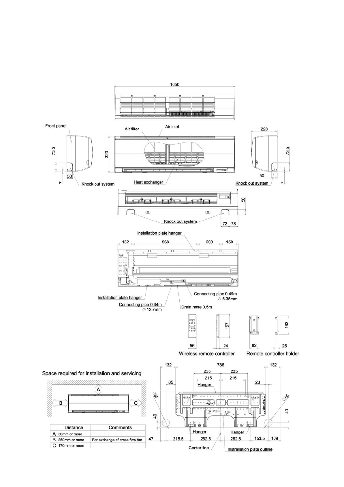
2. CONSTRUCTION VIEWS (EXTERNAL VIEWS)
2-1. 4-Way Air Discharge Cassette Type
RAV-SM566KRT-E(TR)
FILE NO. SVM-12004
– 13 –
Page 14
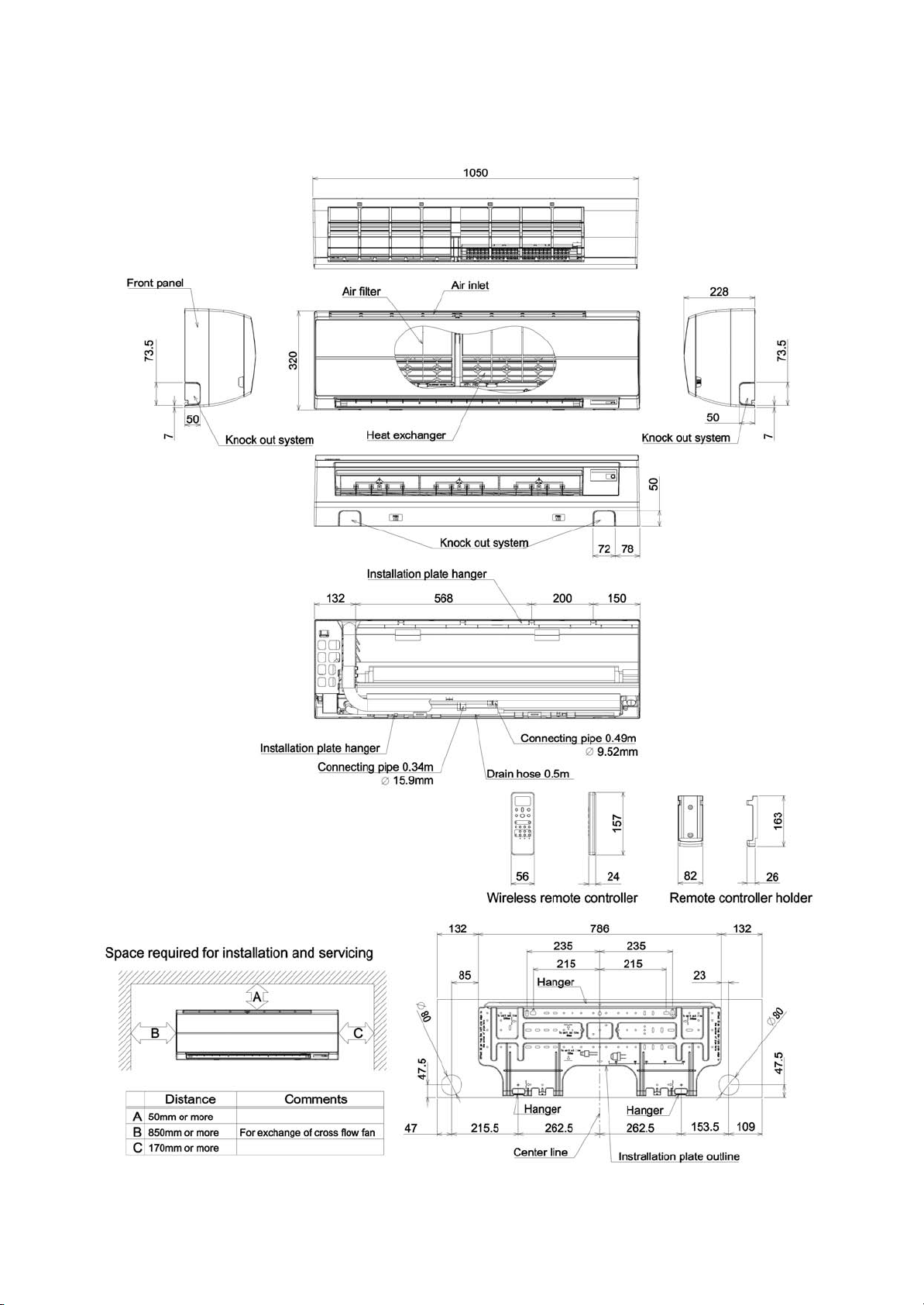
RAV-SM806KRT-E(TR)
FILE NO. SVM-12004
– 14 –
Page 15
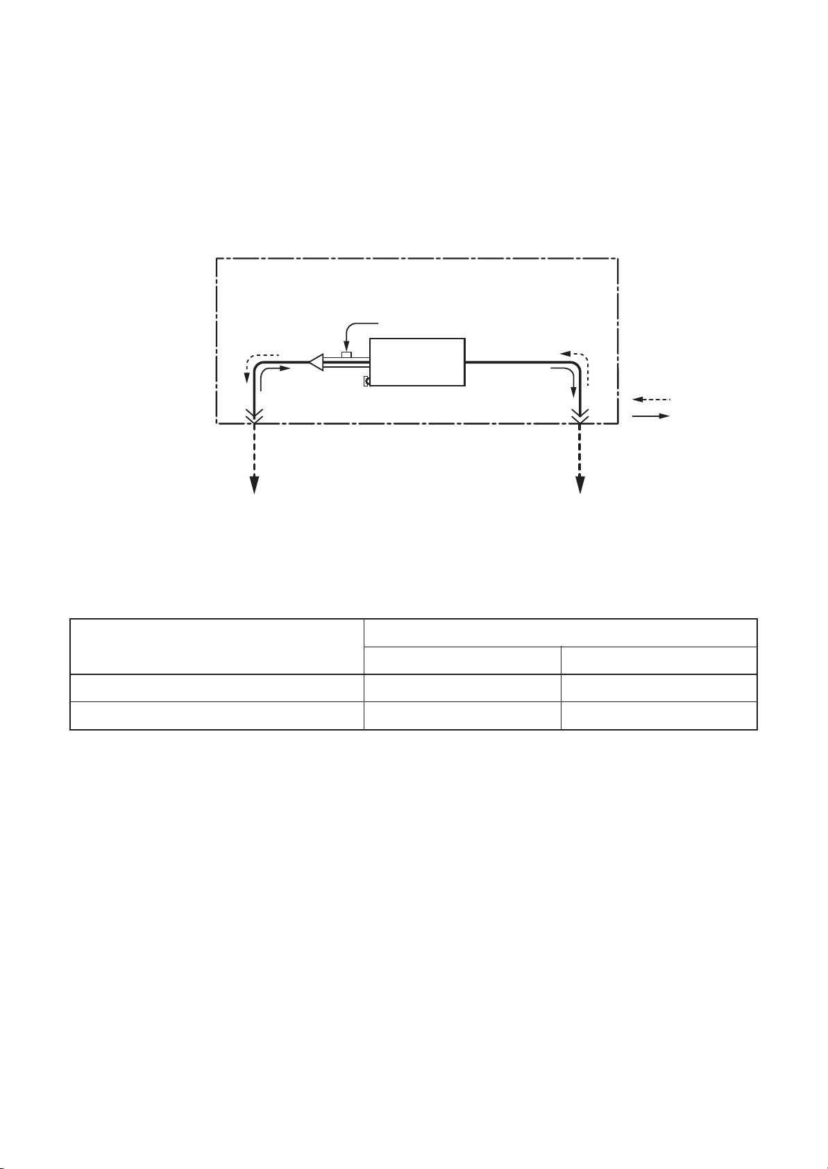
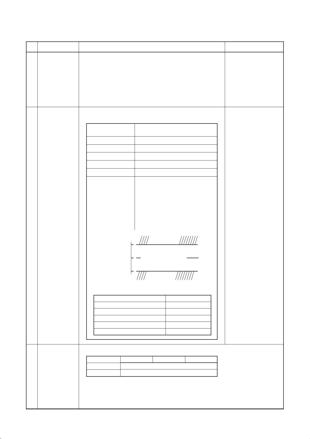
3. SYSTEMATIC REFRIGERATING CYCLE DIAGRAM
High Wall Type
• Single type (Combination of 1 indoor unit and 1 outdoor unit)
FILE NO. SVM-12004
Dimension table
Distributor
(Strainer incorporated)
To outdoor unit
Indoor unit
TC sensor
Refrigerant pipe
at liquid side
(Outer dia : ØB)
(Indoor unit)
TCJ sensor
Air heat
exchanger
Heating
Cooling
Refrigerant pipe
at gas side
(Outer dia : ØA)
To outdoor unit
Outer diameter of refrigerant pipe (In (mm))
Gas side ØA Liquid side ØB
SM56 type
SM80 type
12.7 6.4
15.9 9.5
– 15 –
Page 16

4-1. High Wall Type
4. WIRING DIAGRAM
COLOR
YEL : YELLOW
RED : RED
BLU : BLUE
WHI : WHITE
IDENTIFICATION
B
A
BLU
BLU
1
CN40
2
(BLU)
BLK
BLK
1
321
321
CN41
(BLU)
CN100
(BRW)
CN101
2
(BLU)
CONTROLLER
WIREDREMOTE
2
1
(GRN)
CN103
1
CN102
PNK : PINK
BRW : BROWN
BLK : BLACK
ORN : ORANGE
GRY : GRAY
GRN : GREEN
2
2
1
(YEL)
(WHI)
CN104
FILE NO. SVM-12004
(WHI)
OPTION
(WHI)
CN50
indicates the connection terminal.
indicates the connector on the control P.C. board.
short dashed line indicate the accessories.
1.Broken line indicate the wiring at site. Long dashed
2. indicates the terminal block.
FM
LM
M
BLK
12345
(BRW)
DC15V
DC12V
DC 7V
DC20V
12
3. indicates the protection ground.
CN44
4. indicates the control P.C. board.
POWER
CIRCUIT
CN67
U
(BLK)
SUPPLY
‑
+
+
‑
(WHI)
CN213
12345678910
5
3
1
RED
WHI
BLK
CN309
7
(YEL)
321
Control P.C. board for indoor unit
CN22
(WHI)
CN210
13456
(WHI)
CN33
123456
CN60
123456
(YEL)
CN61
123456
(BLK)
CN81
(MCC‑1510)
12345
(BLU)
CN82
123456
CN32
(WHI)
(GRN)
2
1
123
PNL/EMG
CN80
(MCC‑5044)
ANDINDICATIONPARTS
INFRAREDRAYSRECEIVE
1234567891011
Earth
SCREW
1 2 3
TB01
Earth
SCREW
60Hz1220V
50Hz1220‑240V
(SINGLEPHASE)
N
L
1 2 3
POWERSUPPLY
OUTDOORUNIT
Earth
SCREW
N
1 2 3
1 2 3
L LL
60Hz3N380V
50Hz3N380‑415V
POWERSUPPLY
(3‑PHASE)
OUTDOORUNIT
– 16 –
Page 17
5. SPECIFICATIONS OF ELECTRICAL PARTS
5-3. High Wall Type
FILE NO. SVM-12004
No.
1
Fan motor (for indoor)
2
Grille motor
3
Thermo. Sensor (TA sensor)
4
Heat exchanger sensor (TC sensor)
5
Heat exchanger sensor (TCJ sensor)
Parts Name
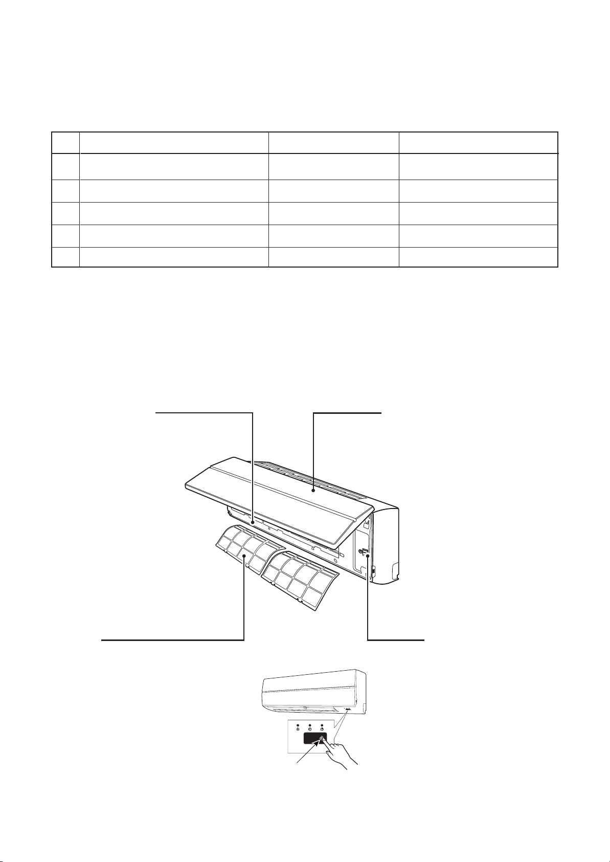
n Name of Each Part
Air outlet / Louver
Change the direction of the air to be
discharged according to cool/heat mode.
Type
ICF-340-U30-1
ICF-340-30X
MF-340-30X
MP24Z3T
318mm
Ø6,800mm
Ø6,800mm
Specications
Output (Rated) 30W, 340V DC
Output (Rated) 1W, 16 poles DC
10kΩ at 25°C
10kΩ at 25°C
10kΩ at 25°C
Air inlet grille
Air in the room is sucked from here.
Air filter
Removes dirt or dust.
(Provided in the air inlet grille)
Earth screw
Earth screws are provided
in the electric parts box.
TEMPORARY button
– 17 –
Page 18

6. REFRIGERANT R410A
FILE NO. SVM-12004
This air conditioner adopts the new refrigerant HFC
(R410A) which does not damage the ozone layer.
The working pressure of the new refrigerant R410A
is 1.6 times higher than conventional refrigerant
(R22). The refrigerating oil is also changed in
accordance with change of refrigerant, so be careful
that water, dust, and existing refrigerant or refrigerating oil are not entered in the refrigerant cycle of
the air conditioner using the new refrigerant during
installation work or servicing time.
The next section describes the precautions for air
conditioner using the new refrigerant.
Conforming to contents of the next section together
with the general cautions included in this manual,
perform the correct and safe work.
6-1. Safety During Installation/Servicing
As R410A’s pressure is about 1.6 times higher than
that of R22, improper installation/servicing may
cause a serious trouble. By using tools and materials exclusive for R410A, it is necessary to carry out
installation/servicing safely while taking the following precautions into consideration.
1. Never use refrigerant other than R410A in an air
conditioner which is designed to operate with
R410A. If other refrigerant than R410A is mixed,
pressure in the refrigeration cycle becomes
abnormally high, and it may cause personal
injury, etc. by a rupture.
2. Confirm the used refrigerant name, and use
tools and materials exclusive for the refrigerant
R410A. The refrigerant name R410A is indicated
on the visible place of the outdoor unit of the air
conditioner using R410A as refrigerant.
To prevent mischarging, the diameter of the
service port differs from that of R22.
3. If a refrigeration gas leakage occurs during
installation/servicing, be sure to ventilate fully.
If the refrigerant gas comes into contact with fire,
a poisonous gas may occur.
4. When installing or removing an air conditioner,
do not allow air or moisture to remain in the
refrigeration cycle.
Otherwise, pressure in the refrigeration cycle
may become abnormally high so that a rupture
or personal injury may be caused.
5. After completion of installation work, check to
make sure that there is no refrigeration gas
leakage. If the refrigerant gas leaks into the
room, coming into contact with fire in the fandriven heater, space heater, etc., a poisonous
gas may occur.
6. When an air conditioning system charged with a
large volume of refrigerant is installed in a small
room, it is necessary to exercise care so that,
even when refrigerant leaks, its concentration
does not exceed the marginal level.
If the refrigerant gas leakage occurs and its
concentration exceeds the marginal level, an
oxygen starvation accident may result.
7. Be sure to carry out installation or removal
according to the installation manual.
Improper installation may cause refrigeration
trouble, water leakage, electric shock, fire, etc.
8. Unauthorized modifications to the air conditioner
may be dangerous.
If a breakdown occurs please call a qualified air
conditioner technician or electrician.
Improper repair may result in water leakage,
electric shock and fire, etc.
6-2. Refrigerant Piping Installation
6-2-1. Piping Materials and Joints Used
For the refrigerant piping installation, copper pipes
and joints are mainly used. Copper pipes and joints
suitable for the refrigerant must be chosen and
installed. Furthermore, it is necessary to use clean
copper pipes and joints whose interior surfaces are
less affected by contaminants.
1. Copper Pipes
It is necessary to use seamless copper pipes
which are made of either copper or copper alloy
and it is desirable that the amount of residual oil
is less than 40 mg/10 m.
Do not use copper pipes having a collapsed,
deformed or discolored portion (especially on the
interior surface).
Otherwise, the expansion valve or capillary tube
may become blocked with contaminants.
As an air conditioner using R410A incurs pressure higher than when using R22, it is necessary
to choose adequate materials.
Thicknesses of copper pipes used with R410A
are as shown in Table 6-2-1.
Never use copper pipes thinner than 0.8 mm
even when it is available on the market.
– 18 –
Page 19
Table 6-2-1 Thicknesses of annealed copper pipes
Thickness (mm)
FILE NO. SVM-12004
Nominal diameter
1/4
3/8
1/2
5/8
Outer diameter (mm)
6.35
9.52
12.70
15.88
R410A R22
0.80 0.80
0.80 0.80
0.80 0.80
1.00 1.00
2. Joints
For copper pipes, flare joints or socket joints are used. Prior to use, be sure to remove all contaminants.
a) Flare Joints
Flare joints used to connect the copper pipes cannot be used for pipings whose outer diameter exceeds
20 mm. In such a case, socket joints can be used.
Sizes of flare pipe ends, flare joint ends and flare nuts are as shown in Tables 6-2-3 to 6-2-6 below.
b) Socket Joints
Socket joints are such that they are brazed for connections, and used mainly for thick pipings whose
diameter is larger than 20 mm.
Thicknesses of socket joints are as shown in Table 6-2-2.
Table 6-2-2 Minimum thicknesses of socket joints
Nominal diameter
1/4
3/8
1/2
5/8
Reference outer diameter of
copper pipe jointed (mm)
6.35
9.52
12.70
15.88
Minimum joint thickness
(mm)
0.50
0.60
0.70
0.80
6-2-2. Processing of Piping Materials
When performing the refrigerant piping installation, care should be taken to ensure that water or dust does not
enter the pipe interior, that no other oil than lubricating oils used in the installed air-water heat pump is used,
and that refrigerant does not leak.
When using lubricating oils in the piping processing, use such lubricating oils whose water content has been
removed. When stored, be sure to seal the container with an airtight cap or any other cover.
1. Flare processing procedures and precautions
a) Cutting the Pipe
By means of a pipe cutter, slowly cut the pipe so that it is not deformed.
b) Removing Burrs and Chips
If the flared section has chips or burrs, refrigerant leakage may occur.
Carefully remove all burrs and clean the cut surface before installation.
c) Insertion of Flare Nut
– 19 –
Page 20
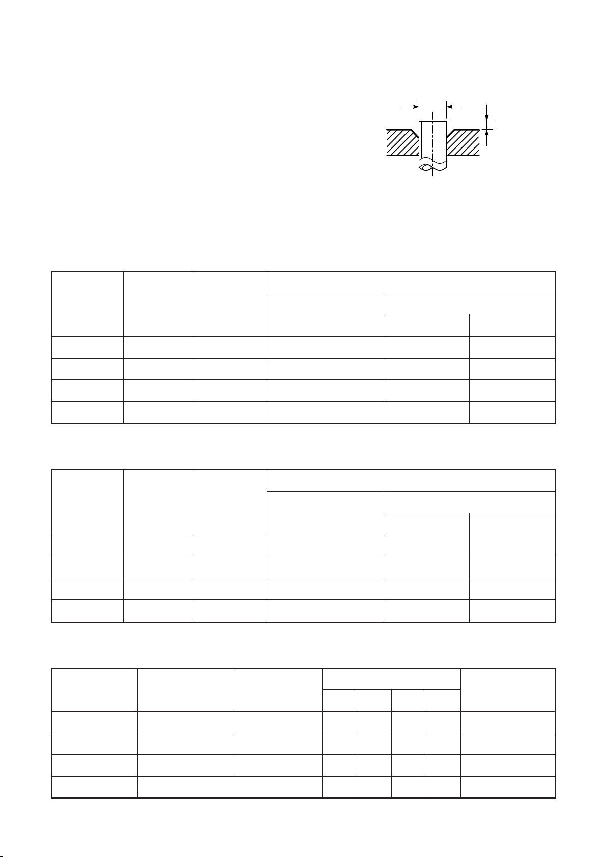
d) Flare Processing
Make certain that a clamp bar and copper
pipe have been cleaned.
By means of the clamp bar, perform the flare
processing correctly.
Use either a flare tool for R410A or conventional flare tool.
Flare processing dimensions differ according
to the type of flare tool.
When using a conventional flare tool, be sure
to secure “dimension A” by using a gauge for
size adjustment.
Table 6-2-3 Dimensions related to flare processing for R410A
FILE NO. SVM-12004
ØD
A
Fig. 6-2-1 Flare processing dimensions
Nominal
diameter
1/4
3/8
1/2
5/8
Nominal
diameter
1/4
3/8
Outer
diameter
(mm)
6.35
9.52
12.70
15.88
Table 6-2-4 Dimensions related to flare processing for R22
Outer
diameter
(mm)
6.35
9.52
Thickness
(mm)
0.8
0.8
0.8
1.0
Thickness
(mm)
0.8
0.8
Flare tool for R410A
clutch type
0 to 0.5 1.0 to 1.5 1.5 to 2.0
0 to 0.5 1.0 to 1.5 1.5 to 2.0
0 to 0.5 1.0 to 1.5 2.0 to 2.5
0 to 0.5 1.0 to 1.5 2.0 to 2.5
Flare tool for R22
clutch type
0 to 0.5 0.5 to 1.0 1.0 to 1.5
0 to 0.5 0.5 to 1.0 1.0 to 1.5
A (mm)
Conventional flare tool
Clutch type Wing nut type
A (mm)
Conventional flare tool
Clutch type Wing nut type
1/2
5/8
Nominal
diameter
1/4
3/8
1/2
5/8
12.70
15.88
Table 6-2-5 Flare and flare nut dimensions for R410A
Outer diameter
(mm)
6.35
9.52
12.70
15.88
0.8
1.0
Thickness
(mm)
0.8
0.8
0.8
1.0
– 20 –
0 to 0.5 0.5 to 1.0 1.5 to 2.0
0 to 0.5 0.5 to 1.0 1.5 to 2.0
Dimension (mm)
ABCD
9.1 9.2 6.5 13
13.2 13.5 9.7 20
16.6 16.0 12.9 23
19.7 19.0 16.0 25
Flare nut width
(mm)
17
22
26
29
Page 21
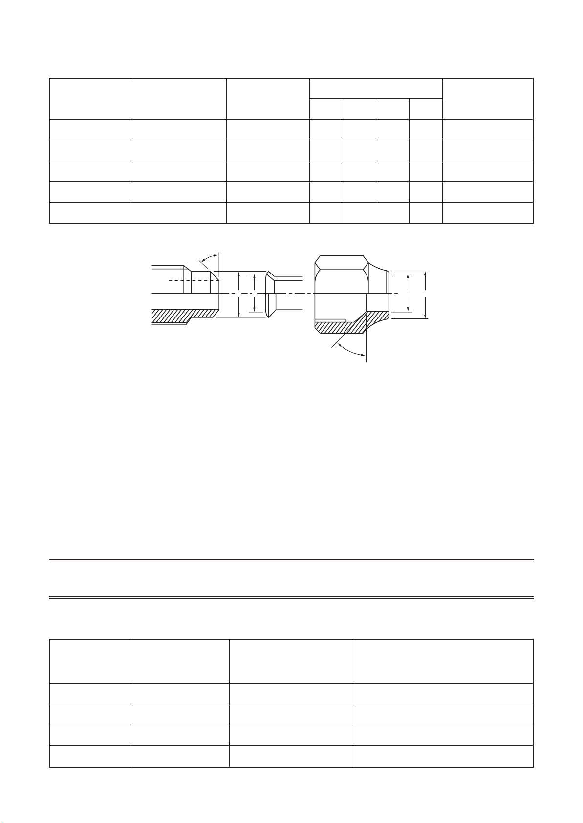
Table 6-2-6 Flare and flare nut dimensions for R22
FILE NO. SVM-12004
Nominal
diameter
1/4
3/8
1/2
5/8
3/4
Outer diameter
(mm)
6.35
9.52
12.70
15.88
19.05
45˚ to 46˚
Thickness
(mm)
0.8
0.8
0.8
1.0
1.0
B A
Dimension (mm)
ABCD
9.0 9.2 6.5 13
13.0 13.5 9.7 20
16.2 16.0 12.9 20
19.7 19.0 16.0 23
23.3 24.0 19.2 34
D
C
43˚ to 45˚
Flare nut width
(mm)
17
22
24
27
36
Fig. 6-2-2 Relations between flare nut and flare seal surface
2. Flare Connecting Procedures and Precautions
a) Make sure that the flare and union portions do not have any scar or dust, etc.
b) Correctly align the processed flare surface with the union axis.
c) Tighten the flare with designated torque by means of a torque wrench.
The tightening torque for R410A is the same as that for conventional R22.
Incidentally, when the torque is weak, the gas leakage may occur.
When it is strong, the flare nut may crack and may be made non-removable. When choosing the
tightening torque, comply with values designated by manufacturers. Table 6-2-7 shows reference
values.
NOTE :
When applying oil to the flare surface, be sure to use oil designated by the manufacturer.
If any other oil is used, the lubricating oils may deteriorate and cause the compressor to burn out.
Table 6-2-7 Tightening torque of flare for R410A [Reference values]
Nominal
diameter
Outer diameter
(mm)
Tightening torque
N•m (kgf•cm)
Tightening torque of torque
wrenches available on the market
N•m (kgf•cm)
1/4
3/8
1/2
5/8
6.35
9.52
12.70
15.88
14 to 18 (140 to 180)
33 to 42 (330 to 420)
50 to 62 (500 to 620)
63 to 77 (630 to 770)
– 21 –
16 (160), 18 (180)
42 (420)
55 (550)
65 (650)
Page 22
FILE NO. SVM-12004
6-3. Tools
6-3-1. Required Tools
The service port diameter of packed valve of the outdoor unit in the air-water heat pump using R410A is
changed to prevent mixing of other refrigerant.
To reinforce the pressure-resisting strength, flare processing dimensions and opposite side dimension of flare
nut (For Ø12.7 copper pipe) of the refrigerant piping are lengthened.
The used refrigerating oil is changed, and mixing of oil may cause a trouble such as generation of sludge,
clogging of capillary, etc. Accordingly, the tools to be used are classified into the following three types.
1. Tools exclusive for R410A (Those which cannot be used for conventional refrigerant (R22))
2. Tools exclusive for R410A, but can be also used for conventional refrigerant (R22)
3. Tools commonly used for R410A and for conventional refrigerant (R22)
The table below shows the tools exclusive for R410A and their interchangeability.
Tools exclusive for R410A (The following tools for R410A are required.)
Tools whose specifications are changed for R410A and their interchangeability
air-water heat pump installation
No.
1
Flare tool
Copper pipe gauge for
2
adjusting projection margin
3
Torque wrench
4
Gauge manifold
5
Charge hose
6
Vacuum pump adapter
Electronic balance for
7
refrigerant charging
8
Refrigerant cylinder
9
Leakage detector
10
Charging cylinder
(Note 1) When flaring is carried out for R410A using the conventional flare tools, adjustment of projection
(Note 2) Charging cylinder for R410A is being currently developed.
Used tool
Pipe flaring
Flaring by
conventional flare tool
Connection of flare nut
Evacuating, refrigerant
charge, run check, etc.
Vacuum evacuating
Refrigerant charge
Refrigerant charge
Gas leakage check
Refrigerant charge
margin is necessary. For this adjustment, a copper pipe gauge, etc. are necessary.
Usage
Existence of Whether conventional
new equipment equipment can be
for R410A used
Yes ∗ (Note 1)
Yes ∗ (Note 1)
Yes
Yes
Yes
Yes
Yes
Yes
(Note 2)
R410A
×
×
×
×
×
×
×
Conventional air-water
heat pump installation
Whether new equipment
can be used with
conventional refrigerant
¡
∗ (Note 1)
×
×
¡
¡
×
¡
×
General tools (Conventional tools can be used.)
In addition to the above exclusive tools, the following equipments which serve also for R22 are necessary as
the general tools.
1) Vacuum pump 7) Screwdriver (+, –)
Use vacuum pump by attaching vacuum pump adapter. 8) Spanner or Monkey wrench
2) Torque wrench 9) Hole core drill (Ø65)
3) Pipe cutter 10) Hexagon wrench (Opposite side 4mm)
4) Reamer 11) Tape measure
5) Pipe bender 12) Metal saw
6) Level vial
Also prepare the following equipments for other installation method and run check.
1) Clamp meter 3) Insulation resistance tester
2) Thermometer 4) Electroscope
– 22 –
Page 23

FILE NO. SVM-12004
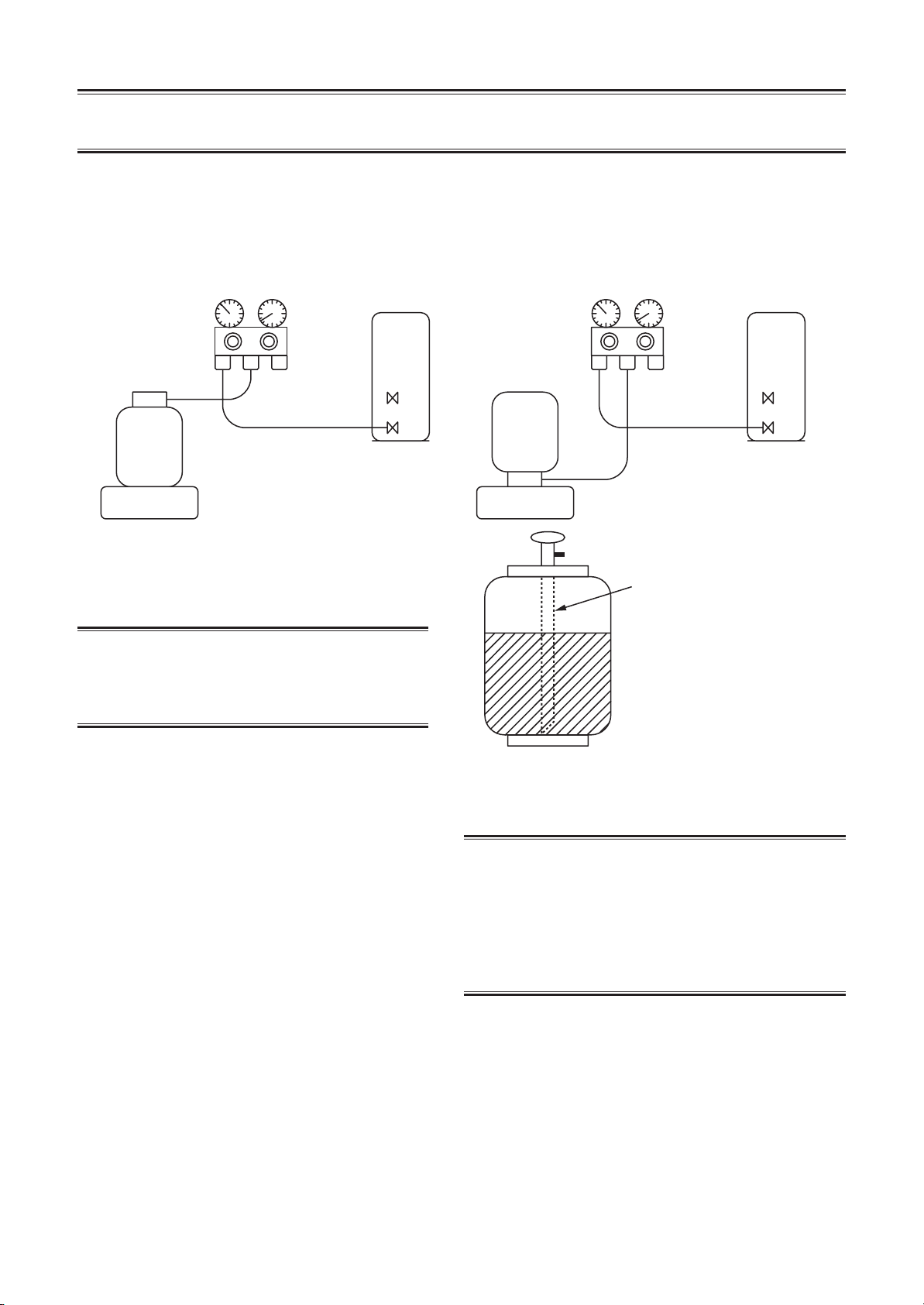
6-4. Recharging of Refrigerant
When it is necessary to recharge refrigerant, charge the specified amount of new refrigerant according to the
following steps.
Recover the refrigerant, and check no refrigerant
remains in the equipment.
When the compound gauge’s pointer has indicated
–0.1 Mpa (–76 cmHg), place the handle Low in the
Connect the charge hose to packed valve service port
at the outdoor unit’s gas side.
fully closed position, and turn off the vacuum pump’s
power switch.
Connect the charge hose to the vacuum pump adapter.
Open fully both packed valves at liquid and gas sides.
Place the handle of the gauge manifold Low in the
fully opened position, and turn on the vacuum pump’s
power switch.
Then, evacuating the refrigerant in the cycle.
Keep the status as it is for 1 to 2 minutes, and ensure
that the compound gauge’s pointer does not return.
Set the refrigerant cylinder to the electronic balance,
connect the connecting hose to the cylinder and the
connecting port of the electronic balance, and charge
liquid refrigerant.
(For refrigerant charging, see the figure below.)
CAUTION
1. Never charge refrigerant exceeding the specified amount.
2. If the specified amount of refrigerant cannot be charged, charge refrigerant bit by bit in COOL mode.
3. Do not carry out additional charging.
When additional charging is carried out if refrigerant leaks, the refrigerant composition changes in the
refrigeration cycle, that is characteristics of the air conditioner changes, refrigerant exceeding the specified
amount is charged, and working pressure in the refrigeration cycle becomes abnormally high pressure, and
may cause a rupture or personal injury.
(INDOOR unit)
Refrigerant cylinder
(With siphon pipe)
Check valve
Open/Close valve
for charging
Electronic balance for refrigerant charging
Fig. 6-4-1 Configuration of refrigerant charging
(Liquid side)
(Gas side)
– 23 –
(OUTDOOR unit)
Opened
Closed
Service port
Page 24
FILE NO. SVM-12004
1. Be sure to make setting so that liquid can be charged.
2. When using a cylinder equipped with a siphon, liquid can be charged without turning it upside down.
It is necessary for charging refrigerant under condition of liquid because R410A is mixed type of refrigerant.
Accordingly, when charging refrigerant from the refrigerant cylinder to the equipment, charge it turning the
cylinder upside down if cylinder is not equipped with siphon.
[ Cylinder with siphon ] [ Cylinder without siphon ]
Gauge manifold
OUTDOOR unit
Refrigerant
cylinder
Gauge manifold
OUTDOOR unit
cylinder
Refrigerant
Electronic
balance
R410A refrigerant is HFC mixed refrigerant.
Therefore, if it is charged with gas, the
composition of the charged refrigerant changes
and the characteristics of the equipment varies.
6-5. Brazing of Pipes
6-5-1. Materials for Brazing
1. Silver brazing filler
Silver brazing filler is an alloy mainly composed
of silver and copper.
It is used to join iron, copper or copper alloy,
and is relatively expensive though it excels in
solderability.
Electronic
balance
Siphon
Fig. 6-4-2
1. Phosphor bronze brazing filler tends to react with
sulfur and produce a fragile compound water
solution, which may cause a gas leakage.
Therefore, use any other type of brazing filler at a hot
spring resort, etc., and coat the surface with a paint.
2. When performing brazing again at time of servicing,
use the same type of brazing filler.
2. Phosphor bronze brazing filler
Phosphor bronze brazing filler is generally
used to join copper or copper alloy.
3. Low temperature brazing filler
Low temperature brazing filler is generally
called solder, and is an alloy of tin and lead.
Since it is weak in adhesive strength, do not
use it for refrigerant pipes.
6-5-2. Flux
1. Reason why flux is necessary
• By removing the oxide film and any foreign matter
on the metal surface, it assists the flow of brazing
filler.
• In the brazing process, it prevents the metal
surface from being oxidized.
• By reducing the brazing filler’s surface tension,
the brazing filler adheres better to the treated metal.
– 24 –
Page 25
FILE NO. SVM-12004
2. Characteristics required for flux
• Activated temperature of flux coincides with
the brazing temperature.
• Due to a wide effective temperature range, flux
is hard to carbonize.
• It is easy to remove slag after brazing.
• The corrosive action to the treated metal and
brazing filler is minimum.
• It excels in coating performance and is harmless to the human body.
As the flux works in a complicated manner as
described above, it is necessary to select an
adequate type of flux according to the type and
shape of treated metal, type of brazing filler and
brazing method, etc.
3. Types of flux
• Noncorrosive flux
Generally, it is a compound of borax and boric
acid. It is effective in case where the brazing
temperature is higher than 800°C.
• Activated flux
Most of fluxes generally used for silver brazing
are this type.
It features an increased oxide film removing
capability due to the addition of compounds
such as potassium fluoride, potassium chloride
and sodium fluoride to the borax-boric acid
compound.
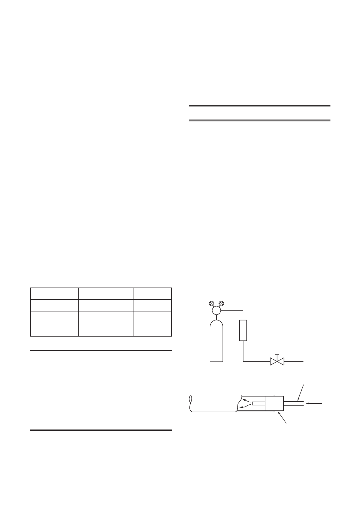
4. Piping materials for brazing and used
brazing filler/flux
6-5-3. Brazing
As brazing work requires sophisticated techniques,
experiences based upon a theoretical knowledge, it
must be performed by a person qualified.
In order to prevent the oxide film from occurring in
the pipe interior during brazing, it is effective to
proceed with brazing while letting dry Nitrogen gas
(N2) flow.
Never use gas other than Nitrogen gas.
1. Brazing method to prevent oxidation
1) Attach a reducing valve and a flow-meter to
the Nitrogen gas cylinder.
2) Use a copper pipe to direct the piping material, and attach a flow-meter to the cylinder.
3) Apply a seal onto the clearance between the
piping material and inserted copper pipe for
Nitrogen in order to prevent backflow of the
Nitrogen gas.
4) When the Nitrogen gas is flowing, be sure to
keep the piping end open.
5) Adjust the flow rate of Nitrogen gas so that it
is lower than 0.05 m3/Hr or 0.02 MPa
(0.2kgf/cm2) by means of the reducing valve.
6) After performing the steps above, keep the
Nitrogen gas flowing until the pipe cools
down to a certain extent (temperature at
which pipes are touchable with hands).
7) Remove the flux completely after brazing.
Piping material
Copper - Copper
Copper - Iron
Iron - Iron
Used brazing filler
Phosphor copper
Silver
Silver
Used flux
Do not use
Paste flux
Vapor flux
1. Do not enter flux into the refrigeration cycle.
2. When chlorine contained in the flux remains
within the pipe, the lubricating oil deteriorates.
Therefore, use a flux which does not contain
chlorine.
3. When adding water to the flux, use water which
does not contain chlorine
(e.g. distilled water or ion-exchange water).
4. Remove the flux after brazing.
M
Flow meter
Stop valve
Nitrogen gas
cylinder
From Nitrogen cylinder
Pipe
Nitrogen
gas
Rubber plug
Fig. 6-5-1 Prevention of oxidation during brazing
– 25 –
Page 26
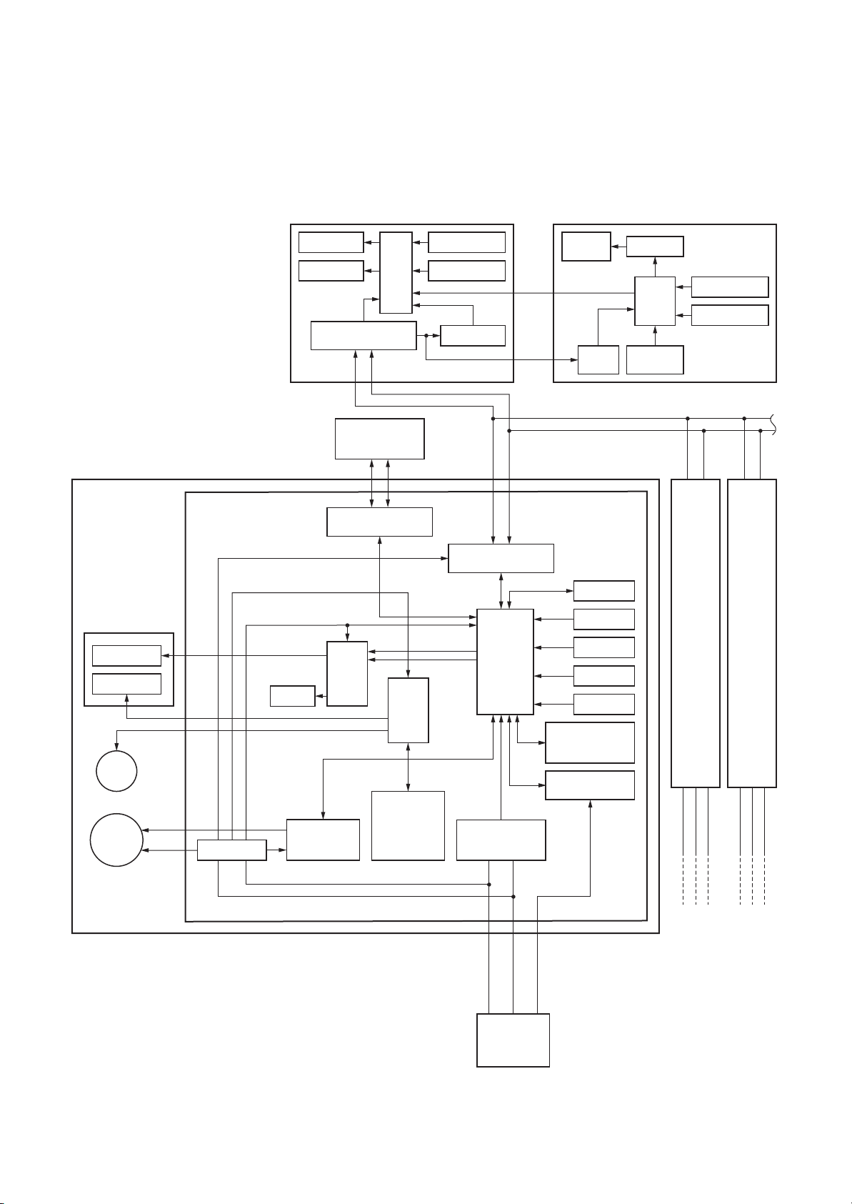
7. INDOOR UNIT CONTROL
7-1. Indoor Controller block diagram
7-1-1. Connection of wired remote controller
Wired (Simple) header remote controller (wired) Central remote controller
FILE NO. SVM-12004
Indoor unit
#1 Header unit
Receiver and
Display P.C. board
(MCC-5044)
Display LED
Receiver unit
Louver
motor
Indoor
fan motor
DC280V
Indoor control P.C. board
(MCC-1510)
DC20V
DC12V
DC5V
Buzzer
Power circuit
control circuit
DC15V
Display LCD Function setup
Display LED
Remote controller
communication circuit
Central control
remote controller
(Sold separately)
U3 U4
Central control
communication circuit
Driver
Outside
output
Fan motor
CPU
Driver
Run/
Alarm/
Ready/
Thermo. ON/
COOL/HEAT/
FAN
Key switch
DC5V
Power circuit
Sold separately Sold separately
AB
Remote controller
communication circuit
synchronous
signal input circuit
CPU
H8/3039
AC
CN2
CN1
∗2
Display
LCD
DC5V
Powe r
circuit
EEPROM
TA sensor
TC sensor
TCJ sensor
HA
Wireless remote
signal setting
(A/B)
Serial send/
receive circuit
LCD driver
CPU
Secondary
battery
Follower unit
#2
Function setup
Key switch
the left
1
32
#3
Same as
the left
1
ABA
Same as
B
32
Max. 8 units are connectable. ∗1
∗1 When group and twin combination.
Main remote controller shal be connected follower indoor unit.
∗2 Weekly timer is not connectable to the sub remote controller.
– 26 –
1
1
2
Outdoor unit
32
3
Outdoor
unit
Outdoor
unit
Page 27

7-1-2. Connection of Wireless Remote Controller
Central control
remote controller
Indoor unit
#1 Header unit
Receiver and
Display P.C. board
(MCC-5044)
Display LED
Receiver unit
Louver
motor
Indoor
fan motor
DC280V
Indoor control P.C. board
(MCC-1510)
DC20V
DC12V
DC5V
Buzzer
Power circuit
control circuit
DC15V
(Sold separately)
U3 U4
Central control
communication circuit
Driver
Fan motor
Driver
Outside
output
Run/
Warning/
Defrost/
Thermo. ON/
COOL/HEAT/
FAN
AB
Remote controller
communication circuit
CPU
H8/3039
AC
synchronous
signal input circuit
SL2L1
FILE NO. SVM-12004
EEPROM
TA sensor
TC sensor
TCJ sensor
HA
Wireless remote
signal setting
(A/B)
Serial send/
receive circuit
Follower unit
#2
the left
321
#3
Same as
the left
1
ABA
Same as
×
Outdoor
unit
Outdoor
unit
B
32
Max. 8 units are connectable. ∗1
∗1 When group combination, wired remote controller shall be
connected to the follower indoor unit.
SL2L1
Outdoor unit
– 27 –
Page 28
7-2. Control Specifications (High Wall Type)
FILE NO. SVM-12004
No.
1
When power
supply is reset
2
Operation
mode selection
Item
Outline of specifications
1) Distinction of outdoor unit
When the power supply is reset, the outdoors are distin-
guished and the control is selected according to the
distinguished result.
2) Setting of indoor fan speed and existence of air direction
adjustment
Based on EEPROM data, select setting of the indoor fan
speed and the existence of air direction adjustment.
1) Based on the operation mode selecting command from the
remote controller, the operation mode is selected.
Remote controller
command
STOP
FAN
COOL
DRY
HEAT
AUTO
Air conditioner stops.
Fan operation
Cooling operation
Dry operation
Heating operation
• COOL/HEAT operation mode is
automatically selected by Ta, Ts
and To for operation.
• The operation is performed as
shown in the following figure
according to Ta value at the first
time only. (In the range of Ts +
Control outline
α –1 < Ta < Ts + α + 1, Cooling
thermo. OFF (Fan)/Setup air
volume operation continues.)
Remarks
Fan speed (rpm)/
Air direction adjustment
Ta: Room temp.
Ts: Setup temp.
To: Outside temp.
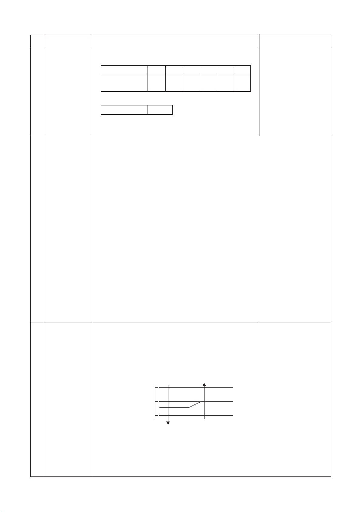
3
Room temp.
control
Cooling
1.0
Ta
Ts +
˚C
• α is corrected according to the outside temperature.
α
–1.0
Outside temp.
No To
To ≥ 24°C
24°C > To ≥ 18°C
To < 18°C
To error
operation
Cooling thermo. OFF (Fan)
• Setup air volume
Heating
operation
Correction value (
0K
–1K
0K
+1K
0K
αα
α)
αα
K = deg
1) Adjustment range: Remote controller setup temperature °C
COOL/DRY HEAT AUTO
Wired type ∗
Wireless type
18°C to 29°C
17°C to 30°C
∗ When use of remote sensor is set (with DN32), even when sensor value is within
the above range in HEAT or AUTO mode, the thermo. sensor turns OFF when Ta
sensor value exceeds 35°C.
– 28 –
Page 29
FILE NO. SVM-12004
No.
3
Room temp.
control
(Continued)
4
Automatic
capacity control
(GA control)
Item
Outline of specifications
2) Using the CODE No. 06, the setup temperature in heating
operation can be corrected.
SET DATA
Setup temp.
correction
2
0
0°C 1°C 2°C
3 4 5
3°C
4°C 5°C
6
Shift of suction
temperature in heating
operation
Remarks
Setting at shipment
SET DATA 3
• When use of remote controller sensor is set (with DN32),
no correction is performed.
1) Based on the difference between Ta and Ts, the operation frequency is instructed to
the outdoor unit.
2) Cooling operation
Every 90 seconds, the room temperature difference between temperature detected by
Ta and Ts and the varied room temperature value are calculated to obtain the
correction value of the frequency command and then the present frequency command
is corrected.
Ta (n) – Ts (n) : Room temp. difference
n : Counts of detection
Ta (n-1) – Ts (n) : Varied room temp. value
n – 1 : Counts of detection of 90 seconds before
3) Heating operation
Every 1 minute (60 sec.), the room temperature difference between temperature
detected by Ta and Ts and the varied room temperature value are calculated to obtain
the correction value of the frequency command and then the present frequency
command is corrected.
Ts (n) – Ta (n) : Room temp. difference
n : Counts of detection
Ta (n) – Ta (n – 1) : Varied room temp. value
n – 1 : Counts of detection of 1 minute before
4) Dry operation
The frequency correction control is same as those of the cooling operation.
However the maximum frequency is limited to approximately “S6”.
Note) When LOW is set up, the maximum frequency is limited to approximately “SB”.
5
Automatic
cooling/heating
control
1) The judgment of selecting COOL/HEAT is carried out as
shown below. When +1.5°C exceeds against Tsh
10 minutes and after thermo.-OFF, heating operation
(Thermo. OFF) exchanges to cooling operation.
Description in the parentheses shows an example of
cooling ON/OFF.
Tsc: Setup temp. in
cooling operation
Tsh: Setup temp. in
heating operation
+ temp. correction
of room temp. control
˚C
Cooling
+1.5
Tsc or Tsh
–1.5
(Cooling OFF)
(Cooling ON)
Heating
When –1.5°C lowers against Tsc 10 minutes and after thermo. OFF, cooling
operation (Thermo. OFF) exchanges to heating operation.
2) For the automatic capacity control after judgment of cooling/heating, see Item 4.
3) For temperature correction of room temp. control in automatic heating, see Item 3.
– 29 –
Page 30
FILE NO. SVM-12004
No.
6
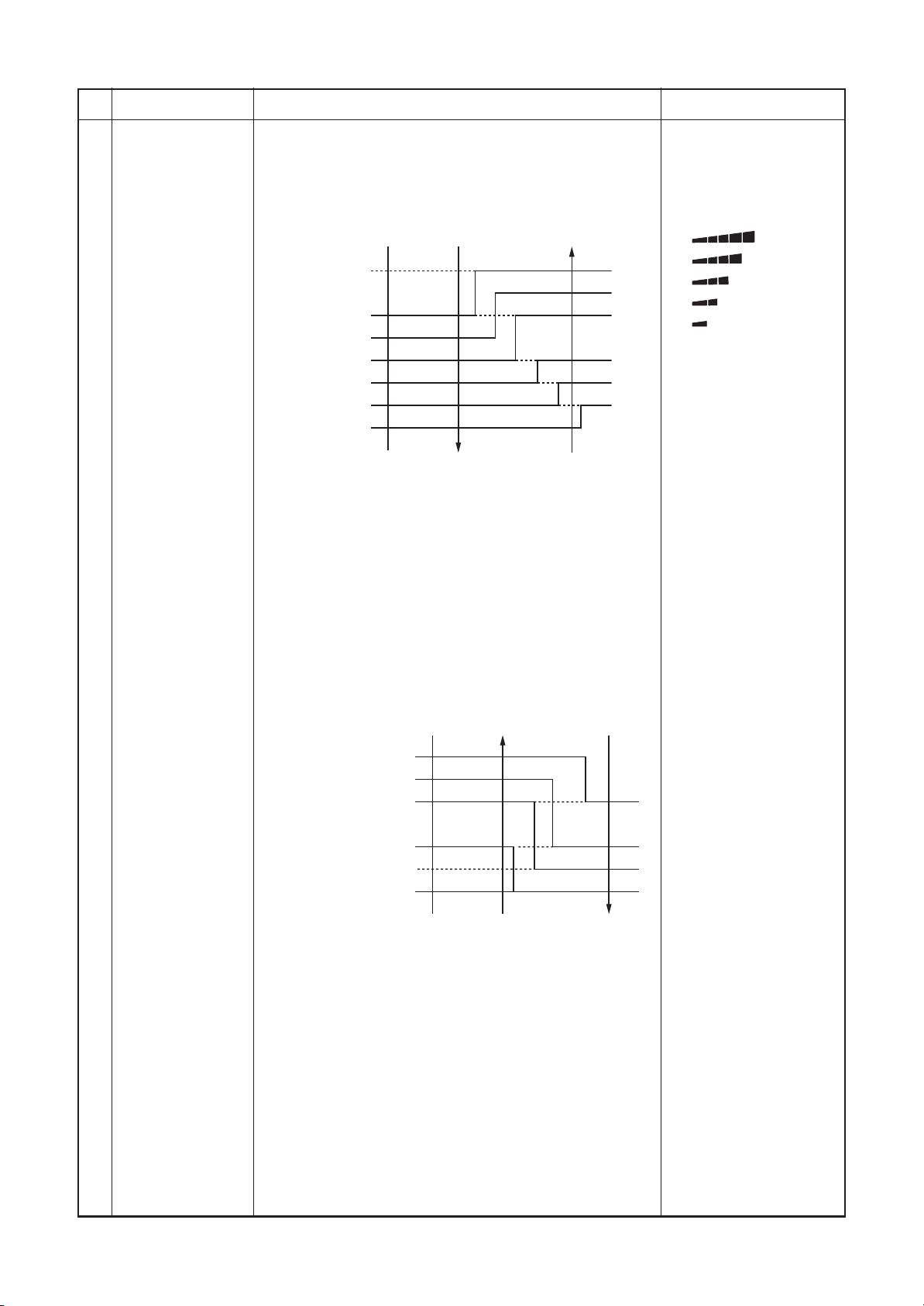
Fan speed control
Item
Outline of specifications
1) Operation with (HH), (H), (L) or [AUTO] mode is carried
out by the command from the remote controller.
2) When the fan speed mode [AUTO] is selected, the fan
speed varies by the difference between Ta and Ts.
<COOL>
Ta ˚C
+3.0
+2.5
+2.0
+1.5
+1.0
+0.5
Tsc
–0.5
HH
(HH)
H+ (HH)
H (HH)
L+ (H+)
L (H)
L (H)
L (L+)
A
B
C
D
E
F
G
• Controlling operation in case when thermo of remote
controller works is same as a case when thermo of the
body works.
• If the fan speed has been changed once, it is not
changed for 3 minutes. However when the air volume is
exchanged, the fan speed changes.
• When cooling operation has started, select a downward
slope for the fan speed, that is, the high position.
• If the temperature is just on the difference boundary, the
fan speed does not change.
• Mode in the parentheses indicates one in automatic
cooling operation.
Remarks
HH > H+ > H > L+ > L >
UL
Wireless type allows HH,
H+, H, L+, L and AUTO.
[HH]
[H+]
[H]
[L+]
[L]
<HEAT>
Ta ˚C
(–0.5) –1.0
(0) Tsh
(+0.5) +1.0
(+1.0) +2.0
(+1.5) +3.0
(+2.0) +4.0
L (L+)
L+ (H)
H (H+)
H+
(HH)
HH
(HH)
E
D
C
B
A
Value in the parentheses indicates one when thermostat of
the remote controller works.
Value without parentheses indicates one when thermostat
of the body works.
• If the fan speed has been changed once, it is not
changed for 1 minute. However when the fan speed I
exchanged, the fan speed changes.
• When heating operation has started, select an upward
slope for the fan speed, that is, the high position.
• If the temperature is just on the difference boundary, the
fan speed does not change.
• Mode in the parentheses indicates one in automatic
heating operation.
• In Tc ≥ 60°C, the fan speed increases by 1 step.
Tc: Indoor heat
exchanger sensor
temperature
– 30 –
Page 31

FILE NO. SVM-12004
No.
6
Fan speed control
(Continued)
Item
Outline of specifications
Fan speed [rpm]
COOL
HH
H+
H
L+
L
UL
HEAT
HH
H+
H
L+
L
UL
SM56
1080
1080
1020
1000
980
980
940
900
500
SM80
1260
1240
1080
1020
980
980
940
900
500
3) When thermo sensor turns OFF during heating, the fan
speed mode becomes UL ( weak).
4) When Ta is 25°C or above at the beginning of HEAT
operation or when canceling defrost mode, H or HH mode
continues for 1 minute from the time when Tc enters zone
E. (Following figure.)
5) The HH fan speed for auto cooling/heating is set to a
speed higher than that for normal cooling/heating.
However, it varies depending on the temperature difference
of Tc during auto heating.
Remarks
“PRE-HEAT
indication
”
7 Cool air discharge
preventive control
Ta
˚C
47
HH+
α
42
HH
1) In heating operation, the indoor fan is controlled based on
the detected temperature of Tc sensor or Tcj sensor. As
shown below, the upper limit of the revolution frequency is
restricted.
However B zone is assumed as C zone for
6 minutes and after when the compressor activated.
In defrost operation, the control value of Tc or Tcj is shifted
6°C.
by
Tc, Tcj
˚C
HH
32
H
30
28
26
20
16
L
UL
OFF
E zone
D zone
C zone
B zone
A zone
In D and E zones, the
priority is given to air
volume selection
setup of remote
controller.
– 31 –
Page 32

FILE NO. SVM-12004
No.
8
Freeze preventive control
(Low temperature release)
Item
Outline of specifications
1) The cooling operation (including Dry operation) is
performed as follows based on the detected
temperature of Tc sensor or Tcj sensor.
When [J] zone is detected for 6 minutes
(Following figure), the commanded frequency is
decreased from the real operation frequency.
After then the commanded frequency changes every
30 seconds while operation is performed in [J] zone.
In [K] zone, time counting is interrupted and the
operation is held.
When [ I ] zone is detected, the timer is cleared and
the operation returns to the normal operation.
If the commanded frequency becomes S0 because
the operation continues in [J] zone, the return
temperature A is raised from 8°C to 12°C until [ l ]
zone is detected and the indoor fan operates
with [L] mode.
[˚C]
8
I
A
K
5
J
Remarks
Tcj:
Indoor heat exchanger
sensor temperature
9 High-temp. release
control
In heating operation, the freeze-preventive control
works if 4-way valve is not exchanged and the
following conditions are satisfied.
(However the temperature for J zone dashing control is
changed from 5°C to –5°C.
<Conditions>
• When
activation.
Q
R
1) The heating operation is performed as follows based on the detected temperature
of Tc sensor or Tcj sensor.
• When [M] zone is detected, the commanded frequency is decreased from the
• In [N] zone, the commanded frequency is held.
• When [L] zone is detected, the commanded frequency is returned to the original
Setup at shipment
or R is established 5 minutes after
Q
Tcn ≤ Tc (n – 1) – 5
Tcn < Tc (n – 1) – 1 and Tcn ≤ Ta < 5°C
real operation frequency. After then the commanded frequency changes every
30 seconds while operation is performed in [M] zone.
value by approx. 6Hz every 60 seconds.
Tc, Tcj
˚C
Control temp. °C
AB
56 52
54 52
A
B
Tcn:
Tc temperature when
5 minutes elapsed
after activation
Tc (n – 1):
Tc temperature at
start time
M
N
L
NOTE:
When the operation has started or when Tc or Tcj < 30°C at start of the
operation or after operation start, temperature is controlled between values in
parentheses of A and B.
– 32 –
Page 33

FILE NO. SVM-12004
No.
10
11
Item
After-heat
elimination
Louver
control
Outline of specifications
When heating operation stops, in some cases, the indoor fan
operates with (L) for approx. 30 seconds.
1) During the first operation after power on, louver position is
controlled automatically according to operation mode
(COOL/HEAT).
Cooling
48°
2) When louver position is controlled by remote controller, the
unit’s microcomputer memorizes the position for use in the next
operation.
∗ The memorized louver position is cleared when power is
turned off, and returns to the state of 1) above.
3) Louver position setting
• Louver position can be set within the range below.
Heating
80°
Remarks
Louver angle: 0°
( full close )
Full close
0°
COOL/DRY HEAT/FAN
4) Swing setting
• Louver moves within the range beloW.
All operation modes
5) When air conditioner opration stops, louver closes
automatically.
It keeps its position in the event of an alarm.
6) Louver tilts upward automatically during preparation for heating.
12 HA control 1) This control is connected to TV control or remote start/stop I/F,
etc, and start/stop are available by HA signal input from the
remote position.
2) This control outputs start/stop status to HA output terminal.
3) I/O specifications conform to JEMA regulations.
Alarm:
A code number (except
F08 and L31) appears
on the remote controller
and the indoor unit stops.
In the group operation,
use this control by
connecting to either
master or follower
indoor unit.
– 33 –
Page 34

FILE NO. SVM-12004
No.
13
Frequency fixed
Item
operation (Test run)
14
Filter sign display
(Except wireless type)
∗ It is provided on the
separately sold type
TCB-AX21
TCB-AX32E2
E2
Outline of specifications
<In case of wireless remote controller>
1) Push [ON/OFF]
2) Using [SELECT]
button.
MODE
button, set [COOL] or [HEAT] to
the operation mode to drive the air conditioner.
3) Set [HIGH
] to the fan speed.
4) To change the temperature setting, repeat it 6 times
to COOL and HEAT operations each.
17°C ↔ 18°C
COOL:
17°C → 18°C → 17°C
18°C → 17°C → 18°C
→
17°C → (test run) → ON/OFF
→
30°C ↔ 29°C
HEAT:
30°C → 29°C → 30°C
29°C → 30°C → 29°C
→
30°C → (test run) → ON/OFF
→
• Change an operation setting within 3 seconds.
• The error detection is performed as usual.
• The frequency-fixed operation is performed.
5) To finish a test run, push [ON/OFF]
1)
The operation time of the indoor fan is calculated, the
button.
filter reset signal is sent to the remote controller when
the specified time (150H) has passed, and it is displayed
on LCD.
2) When the filter reset signal has been received from
the remote controller, time of the calculation timer is
cleared.
In this case, the measurement time is reset if the
specified time has passed, and display on LCD
disappears.
Remarks
FILTER [ ] goes on.
Central control mode
15
selection
1) Setting at the central controller side enables to select
the contents which can be operated on the remote
controller at indoor unit side.
2) RBC-AMT32
E2
[Last push priority] :
The operation contents can be selected from both
remote controller and central controller of the indoor
unit side, and the operation is performed with the
contents selected at the last.
[Center] :
Start/Stop operation only can be handled on the
remote controller at indoor unit side.
[Operation Prohibited] :
It cannot be operated on the remote controller at
indoor unit side. (Stop status is held.)
(No display)
[CENTER] goes on.
[CENTER] goes on.
In a case of wireless
type, the display lamp
does not change.
However, contents which
can be operated are same.
The status set in
[CENTER]/[Operation
Prohibited] mode is
notified with the
receiving sound
“Pi, Pi, Pi, Pi, Pi” (5 times).
– 34 –
Page 35

FILE NO. SVM-12004
No.
16
Power-saving
control
17
Max. frequency
cut control
Item
Outline of specifications
1) Power-saving opration is available in the AUTO mode.
2) The set temperature is corrected using various sensor data
within the range where comfort is maintained.
3) By using various sensor data including room temp. Ta, outside
air temp. To, fan speed, and indoor unit heat exchange sensor
temp. Tc, 20 minutes data is averaged to calculate a set
temperature correction value.
4) The set temperature is corrected every 20 minutes with the
following shift range.
Cooling: +1.5 to –1.0K
Heating: –1.5 to +1.0K
1) This control is operated by selecting [AUTO] operation mode.
2) COOL operation mode:
It is controlled according to the following figure if To <28°C.
Ta
˚C
Normal control
+4
+3
Remarks
Tsc
Max. frequency is
restricted to approximately
the rated cooling frequency
3) HEAT operation mode:
It is controlled according to the following figure if To >15°C.
Ta
˚C
Tsh
–3
–4
Max. frequency is
restricted to approximately
the rated heating frequency
Normal control
18 DC motor 1) When the fan operation has started, positioning of the stator
and the rotor are performed. (Moves slightly with tap sound)
2) The motor operates according to the command from the indoor
controller.
Notes)
• When the fan rotates while the air conditioner stops due to
entering of outside air, etc, the air conditioner may operate while
the fan motor stops.
• When a fan lock is found, the air conditioner stops, and an error
is displayed.
Check code [P12]
– 35 –
Page 36

FILE NO. SVM-12004
No.
19
Self-clean operation
(Dry operation)
Item
Outline of specifications
Remarks
1) When cooling operation mode (AUTO COOL, COOL, DRY) stopped, the following
three self-clean operations are performed.
Compressor
ON period
0 to 10 min.
10 to 60 min.
60 min. to
2) During operation of self-clean,
remote controller screen. However the operation lamp
(Green LED) goes off.
3) To stop the self-clean operation, push twice the
[ON/OFF] button on the remote controller continuously.
(Stop the operation as compressor ON time in the table
above: 10 minutes or below.)
4) When the follower unit executes self-clean oper ation in the
group connection, the segment of
wired remote controller screen via master unit.
∗ If self-clean operation is not used, set invalidity
(does not use) of the self-clean operation by changing
Self-clean
operation period
None
1 hour
2 hours
FAN
450 rpm
Position of 15° from all closes
lights on the wired
is displayed on the
Louver
On the remote controller before the wired
remote controller
(RBC-AMT31E),
Self-clean operation
display is not output.
And it is not also on
the wireless remote
controller.
It is recognized as
[STOP] from the
remote monitor side.
[0001 (At shipment) of Item code (DN) [D3] to [0000].
∗ To erase the
display during operation of self-clean,
change Item code [D4] from [0000: Display
(At shipment)] to [0001: Non-display].
20 Save operation
(Wired remote
controller specific
operation)
1) Turn on
2) During operation of save operation,
remote controller.
3) During save operation, the current release control is performed
with the restriction ratio set in EEPROM on the outdoor unit.
4) The restriction ratio can be set by keeping
pushed for 4 seconds or more on the remote controller.
5) When validating the save operation, the next operation starts
with save operation valid because contents are held even
when operation stops, operation mode changes or power
supply is reset.
6) The restriction ratio can be set by changing the setup data of
CODE No. (DN) [C2] in the range of 50 to 100%
(every 1%, Setting at shipment: 75%).
21 Auto restart 1) Object
It restarts the operation automatically after resetting the
unexpected stop of power supply such as power failure.
2) Contents
After returning from a power failure, the auto restart function
reads the operation status from EEPROM and then restarts
the operation automatically according to the operation
contents.
3) Setup of function exchange by wired remote controller
CODE No. (DN): 28
SET DATA
Auto restart
SAVE
button on the wired remote controller.
lights on the wired
0000
None (At shipment)
SAVE
button
0001
Provided
Carry out setting
operation during stop of
the unit; otherwise the
unit stops operation.
For the setup operation,
refer to “How to set up
contents of save
operation” of
“10. SETUP AT LOCAL
SITE AND OTHERS”.
– 36 –
Page 37

FILE NO. SVM-12004
No.
22 8°C
heating/
Frost protective
operation
(Wired remote
controller specific
operations)
Item Outline of specifications
1) This function is intended for the cold latitudes and performs
objective heating operation 8°C heating operation).
2)
This function is valid only for combination with the outdoor units.
3) Using the indoor CODE No. [D1] (1 bit), Valid/Invalid of this
function is set up at the customer’s side.
∗ The setup by CODE No. is Invalid [0]/Valid [1] and Invalid
[0] has been set at the shipment.
4) This operation is the heating operation which sets
8°C as the setup temperature of the target.
5) This function starts operation by pushing temperature button
during heating operation; besides by pushing
button for 4 seconds or more after temperature reached the
minimum set temperature.
6) To stop/release this operation, select and execute one from
the following operations.
Push button:
Q
Heating operation 18°C setting) continues.
Push [START/STOP] button:
R
Air conditioner stops.
(Heating 18°C operation at the next start)
Push
S
MODE
:
Other operation mode is selected and the operation
continues.
7) As the setup temperature is 8°C and the human
heating is not targeted, the cold air discharge preventive
control (Item 7) is made invalid to suppress the intermittent
operation.
8) The settings of the air direction and air volume are
changeable during this operation.
9) The indoor fan stops to protect the compressor for
2 minutes after start of heating operation (Thermo-ON) by
this function.
Remarks
In a group connection,
if there is even one
combination with other
unit, “This function is not
provided.” is displayed.
The setup temperature
jumps from [18] to [8].
23 Hi POWER
operation
(Wireless remote
controller specific
operations)
When you push the Hi POWER button during cooling,
heating or AUTO, the air conditioner will start the following
operation.
• Cooling operation
Performs the cooling operation at
1°C lower than
the setting temperature.
Only when the fan speed before the Hi POWER operation
is not high, the fan speed will be increased.
• Heating operation
Performs the heating operation at
2°C higher
than the setting temperature.
Only when the fan speed before the Hi POWER operation
is not high, the fan speed will be increased.
• [Hi POWER] Display
– 37 –
Page 38

FILE NO. SVM-12004
No.
Item Outline of specifications Remarks
24 COMFORT SLEEP
operation
(Wireless remote
controller specific
operations)
When you push the COMFORT SLEEP button during
cooling, heating or AUTO, the air conditioner will start the
following operation.
The fan speed display will indicate AUTO and low speed will
be used.
• Cooling operation
In the operation suppression zone, where capacity is kept
to the minimum, overcooling is prevented by raising the
temperature setting by +1°C after 1 hour and by
+2°C after
2 hours of operation.
The room temperature is thus regulated between the
operation suppression zone and the set temperature.
When the OFF timer is simultaneously set, 1, 3, 5 and 9
hours appear by turns every pushing COMFORT SLEEP
button and one of them can be selected for OFF timer.
• Heating operation
In the operation suppression zone, where capacity is kept
to the minimum, overheating is prevented by lowering the
temperature setting by +1°C after 1 hour and by
+2°C after
2 hours of operation.
The room temperature is thus regulated between the set
temperature and the operation suppression zone.
When the OFF timer is simultaneously set, 1, 3, 5 and 9
hours appear by turns every pushing COMFORT SLEEP
button and one of them can be selected for OFF timer.
•[
] display
+1˚C
1 hour
Operation starts
Operation suppression zone
+2˚C
2 hours
Set temperature
Set temperature
+1˚C
1 hour
Operation starts
2 hours
2˚C
+
Operation
suppression zone
– 38 –
Page 39

FILE NO. SVM-12004
No.
25
PRESET operation
(Wireless remote
controller specific
operations)
26
(Wireless remote
controller specific
operation)
Item
Outline of specifications
Start the air conditioner in the operation mode which you want the
remote controller to memorize.
1) Push and hold the PRESET button for more than 3 seconds
while the display flashes.
The mark is indicated and the setting is memorized.
• If you do not push the PRESET button within 3 seconds or if
you push another button, the memory setting is cancelled.
• Operation modes which can be memorized with the PRESET
button are MODE, Temperatures, FAN, TIMER and Hi POWER.
To operate the air conditioner with the setting memorized by the
PRESET button.
1) Push the PRESET button briefly.
The setting memorized will be indicated and the air conditioner
operates with regards to the setting.
• The lamp (green) on the display panel of the indoor unit goes
on, and operation starts after approximately 3 minutes.
• Initial setting:
MODE : AUTO
Temperature : 22°C
When you push the QUIET button during cooling, heating, fan only
or AUTO, the air conditioner will start the following operation.
• The fan speed display will indicate AUTO and low speed will be
used.
Remarks
•[ ] display
•[
] displayQUIET operation
27
SLEEP operation
(Wireless remote
controller specific
operation)
When the OFF timer is set, 1, 3, 5 and 9 hours appear by turns
every pushing SLEEP button and one of them can be selected for
OFF timer.
– 39 –
Page 40

7-3. Indoor Print Circuit Board (High Wall Type)
<MCC-1510>
FILE NO. SVM-12004
HA (T10)
CN61, DC 12V
Option output
CN60, DC 12V
CHK
CN71, DC 5V
DISP
CN72, DC 5V
Outside error input
CN80, DC 12V
EXCT
CN73, DC 5V
Remote controller
power LED
D203
TCJ sensor
CN102, DC 5V
TC sensor
CN101, DC 5V
Microcomputer operation LED
D02
EEPROM
IC10
Inter-unit wire
CN67, AC 200V
Option power supply
CN309, AC 220-240V
Central control
CN40, DC ± 5V
TA sensor
CN104, DC 5V
Remote controller
CN41, DC 20V
Fan drive
CN32, DC 12V
Louver
CN33, DC 20V
DC fan input/output
CN210
Terminator resistor provided/not provided
Remote controller A/B switch
SW01
Display output/Wireless sensor
CN213, DC 5V
– 40 –
Page 41

FILE NO. SVM-12004
High Wall Type P.C. board optional switch/Connector specifications
Function
Terminator resistor
provided/Not provided
Remote controller A/B
Fan output
HA
Connector
No.
SW01
CN32
CN61
Pin
No.
Bit 1
Bit 2
1
2
1
2
3
4
5
6
1
2
3
Specifications
OFF: No terminator resistor,
ON: Terminator resistor provided
OFF: Remote controller A
ON: Remote controller B
DC12V
Output
Start/Stop input
0V (COM)
Handy prohibition input
Operation output
DC12V (COM)
Alarm output
DC12V (COM)
Defrost output
Thermo-ON output
Remarks
Setup at shipment OFF: No terminator resistor.
Only 1 unit is ON during central control by custom only.
Setup at shipment OFF: Remote controller A
Setup at shipment: Linked operation of ON with operation of
indoor unit and OFF with stop
* The setup of single operation by FAN button on remote
controller is executed from remote controller. (DN = 31)
HA Start/Stop input (J01: Provided/Not provided =
Pulse (At shipment from factory)/Static input switch)
Operation stop of handy remote controller is permitted /
prohibited by input.
ON during operation (Answer back of HA)
ON during output of alarm
ON during defrosting of outdoor unit
ON when Real thermo. ON (Comp. ON)
Optional output
Outside error input
CHK
Operation check
DISP
Display mode
EXCT
Demand
CN60
CN80
CN71
CN72
CN73
4
Cooling output
5
Heating output
6
Fan output
1
DC12V (COM)
2
DC12V (COM)
3
Filter/Option/Outside error input
1
Check mode input
2
0V
1
Display mode input
2
0V
1
Demand input
2
0V
ON when operation mode is cooling line
(Cool, Dry, Cooing/Heating AUTO cooling)
ON when operation mode is heating line
(Heat, Cooling/Heating AUTO heating)
ON when indoor fan is ON
At shipment from factory, the error code “L30” generates and
optional error input to stop operation forcedly (DN:2A = 1) is
controlled (Display of protection for devices attached to outside)
by setup of outside error input (DN:2A = 2) for 1 minute.
*
Optional error input control is set up on the remote controller.
This check is used for operation check of indoor unit.
(The specified operation such as indoor fan “H”, drain pump
ON, etc. is executed without communication with outdoor unit
or remote controller.)
Display mode, communication is enabled by indoor unit and
remote controller only.
(When power supply is turned on.)
Timer short (Usual)
Indoor unit forced thermo-OFF operation
– 41 –
Page 42

8. TROUBLESHOOTING
8-1. Summary of Troubleshooting
<Wired remote controller type>
1. Before troubleshooting
1) Required tools/instruments
• + and
• Tester, thermometer, pressure gauge, etc.
2) Confirmation points before check
a) The following operations are normal.
1. Compressor does not operate.
2. Indoor fan does not rotate.
3. Outdoor fan does not rotate or air volume changes.
4. ON/OFF operation cannot be performed from remote controller.
b) Did you return the wiring to the initial positions?
c) Are connecting wires of indoor unit and remote controller correct?
–
screwdrivers, spanners, radio cutting pliers, nippers, push pins for reset switch
• Is not 3-minutes delay (3 minutes after compressor OFF)?
• Is not the outdoor unit in standby status though the remote controller reached the setup
temperature?
• Does not timer operate during fan operation?
• Is not an overflow error detected on the indoor unit?
• Is not outside high-temperature operation controlled in heating operation?
• Does not cool air discharge preventive control work in heating operation?
• Does not high-temperature release operation control work in heating operation?
• Does not outside low-temperature operation control work in cooling operation?
• Is not defrost operation performed?
• Is not the control operation performed from outside/remote side?
• Is not automatic address being set up?
(When the power is turned on at the first time or when indoor unit address setting is changed, the
operation cannot be performed for maximum approx. 5 minutes after power-ON.)
• Is not being carried out a test run by operation of the outdoor controller?
FILE NO. SVM-12004
2. Troubleshooting procedure
When a trouble occurred, check the parts along with the following procedure.
Trouble Confirmation of check code display Check defective position and parts.
NOTE :
For cause of a trouble, power conditions or malfunction/erroneous diagnosis of microcomputer due to outer
noise is considered except the items to be checked.
If there is any noise source, change the cables of the remote controller to shield cables.
→→
– 42 –
Page 43

<Wireless remote controller type>
1. Before troubleshooting
1) Required tools/instruments
•+ and – screwdrivers, spanners, radio cutting pliers, nippers, etc.
• Tester, thermometer, pressure gauge, etc.
2) Confirmation points before check
a) The following operations are normal.
1. Compressor does not operate.
• Is not 3-minutes delay (3 minutes after compressor OFF)?
• Is not the outdoor unit in standby status though the remote controller reached the setup
temperature?
• Does not timer operate during fan operation?
• Is not an overflow error detected on the indoor unit?
• Is not outside high-temperature operation controlled in heating operation?
2. Indoor fan does not rotate.
• Does not cool air discharge preventive control work in heating operation?
3. Outdoor fan does not rotate or air volume changes.
• Does not high-temperature release operation control work in heating operation?
• Does not outside low-temperature operation control work in cooling operation?
• Is not defrost operation performed?
4. ON/OFF operation cannot be performed from remote controller.
• Is not forced operation performed?
• Is not the control operation performed from outside/remote side?
• Is not automatic address being set up?
• Is not being carried out a test run by operation of the outdoor controller?
b) Did you return the wiring to the initial positions?
c) Are connecting wires between indoor unit and receiving unit correct?
FILE NO. SVM-12004
2. Troubleshooting procedure
(When the power is turned on at the first time or when indoor unit address setting is changed, the operation
cannot be performed for maximum approx. 5 minutes after power-ON.)
When a trouble occurred, check the parts along with the following procedure.
Trouble
1) Outline of judgment
The primary judgment to check where a trouble occurred in indoor unit or outdoor unit is performed with
the following method.
fi
Confirmation of lamp displ
ay
fi
Method to judge the erroneous position by flashing indication on the display part of indoor unit
(sensors of the receiving unit)
The indoor unit monitors operating status of the air conditioner, and the blocked contents of
self-diagnosis are displayed restricted to the following cases if a protective circuit works.
Check defective
position and parts.
– 43 –
Page 44

FILE NO. SVM-12004
8-2. Troubleshooting (High Wall Type)
8-2-1. Outline of judgment
The primary judgment to check whether a trouble occurred in the indoor unit or outdoor unit is carried out with
the following method.
Method to judge the erroneous position by flashing indication on the display part of the indoor unit
The indoor unit monitors the operating status of the air conditioner, and the blocked contents of self-diagnosis
are displayed restricted to the following cases if a protective circuit works.
Lamp indication
Ready Timer
No indication at all
Ready Timer
Ready Timer
Flash
Operation
Operation
Flash
Operation
Check code
—
E01
E02
E03
E08
E09
E10
E18
E04
: Go off, : Go on,
Cause of trouble occurrence
Power supply OFF or miswiring between receiving unit and indoor unit
Receiving error
Sending error
Communication stop
Duplicated indoor unit No.
Duplicated master units of remote controller
Communication error between CPUs on indoor unit P.C. board
Wire connection error between indoor units, Indoor power OFF
(Communication stop between indoor master and follower or between main
and sub indoor twin)
Miswiring between indoor unit and outdoor unit or connection erorr
(Communication stop between indoor and outdoor units)
⎫
⎬
Receiving unit
⎭
⎫
⎪
Miswiring or wire connection error
⎬
between receiving unit and indoor unit
⎪
⎭
⎫
Setup error
⎬
⎭
: Flash (0.5 sec.)
Ready Timer
Alternate flash
Ready Timer
Alternate flash
Operation
Operation
P01
P10
P12
P03
P04
P05
P07
P15
P19
P20
P22
P26
P29
P31
Indoor AC fan error
Overflow was detected. Protective device of indoor unit worked.
Indoor DC fan error
Outdoor unit discharge temp. error
Outdoor high pressure system error Protective device of
Case thermostat worked outdoor unit worked.
Power supply error
Power supply error
Heat sink overheat error Outdoor unit error
Gas leak detection error
4-way valve system error (Indoor or outdoor unit judged.)
Outdoor unit high pressure protection
Outdoor unit: Outdoor unit error
Outdoor unit: Inverter Idc operation ∗1
Outdoor unit: Position detection error
Stopped because of error of other indoor unit in a group
(Check codes of E03/L03/L07/L08)
⎫
⎪
⎪
⎬
⎪
⎪
⎭
⎫
⎪
⎬
⎪
⎭
⎫
⎪
⎬
⎪
⎭
⎫
⎪
Protective device of
⎬
outdoor unit worked.
⎪
⎭
∗1
∗1: These are representative examples and the check code differs according to the outdoor unit to be combined.
– 44 –
Page 45

FILE NO. SVM-12004
Lamp indication
Ready Timer
Alternate flash
Ready Timer
Alternate flash
Ready Timer
Simultaneous flash
Ready Timer
Operation
Operation
Operation
Operation
Check code
F01
F02
F10
F04
F06
F07
F08
F12
F13
F15
F29
Cause of trouble occurrence
Heat exchanger sensor (TCJ) error
Heat exchanger sensor (TC) error Indoor unit sensor error
Heat exchanger sensor (TA) error
Discharge temp. sensor (TD) error
Temp. sensor (TL, TS, TE) error
Temp. sensor (TD) error
Temp. sensor (TO) error Sensor error of outdoor unit ∗1
Temp. sensor (TS) error
Heat sink sensor (TH) error
Temp. sensor miswiring (TE, TS)
⎫
⎪
⎪
⎬
⎪
⎪
⎭
⎫
⎪
⎪
⎪
⎪
⎪
⎬
⎪
⎪
⎪
⎪
⎪
⎭
Indoor EEPROM error
Simultaneous flash
Ready Timer
Operation
Flash
Ready Timer Operation
Simultaneous flash
Ready Timer
Operation
Simultaneous flash
F31
H01
H02
H03
H04
L03
L07
L08
L09
L10
L20
L29
Outdoor EEPROM error
Compressor break down
Compressor lock
⎫
⎬
Outdoor compressor system error ∗1
⎭
Current detection circuit error } Power supply, outdoor P.C. board error
Case thermostat worked. }
Duplicated master indoor units
There is indoor unit of group → AUTO address
connection in individual indoor unit.
Unsetting of group address
Missed setting
Compressor overheat, outdoor wiring error
⎫
⎪
⎬
⎪
∗ If group construction and address
⎭
are not normal when power supply
turned on, automatically goes to
address setup mode.
(Unset indoor capacity)
Unset model type (Service board)
Duplicated indoor central addresses
Temp. sensor (TH) error
EEPROM error
Communication between outdoor MCU
Heat sink overheat error
Gas leak detection error
4-way valve error
L30
Outside interlock error
∗1: These are representative examples and the check code differs according to the outdoor unit to be combined.
– 45 –
Page 46

8-2-2. Others (Other than Check Code)
FILE NO. SVM-12004
Lamp indication
Ready Timer
Simultaneous flash
Ready Timer
Alternate flash
Operation
Operation
Check code
—
—
Cause of trouble occurrence
During test run
Disagreement of cool/heat
(Automatic cool/heat setting to automatic cool/heat prohibited model, or
setting of heating to cooling-only model)
– 46 –
Page 47

continuation
¡ ×
¡ ×
¡ ×
reset
Automatic Operation
Air conditioner operation
¡ ×
××
××
¡ ×
¡ ×
××
¡ ×
×
××
××
××
××
¡
¡ ×
¡ ×
continuation
——
——
reset
Automatic Operation
Air conditioner operation
×
FILE NO. SVM-12004
continuation
——
——
——
reset
Automatic Operation
Air conditioner operation
——
Explanation of error contents
Representative defective position
: Go off ALT (Alternate): Alternate flashing when there are two flashing LED SIM (Simultaneous): Simultaneous flashing when there are two flashing LED
l
: Flash,
¥
No communication from remote controller and network adapter
(Also no communication from central control system)
There is error on serial communication between indoor and outdoor units
Same address as yours was detected.
Regular communication between indoor master and follower units is impossible,
²
Regular communication error between indoor and
remote controller
Indoor/Outdoor serial error
Duplicated indoor addresses
Regular communication error between
Flash
Communication between twin master (main) and follower (sub) units is impossible.
Open/short was detected on heat exchanger (TCJ).
Open/short was detected on heat exchanger (TC).
Open/short was detected on room temp. sensor (TA).
EEPROM error (Other error may be detected. If no error, automatic address is repeated.
indoor master and follower units
Indoor unit, Heat exchanger (TCJ) error
Indoor unit, Heat exchanger (TC) error
Indoor unit, Room temp. sensor (TA) error
Indoor unit, other indoor P.C. board error
ALT
ALT
ALT
SIM
There are multiple master units in a group.
When even one group connection indoor unit exists in individual indoor unit.
Indoor group address is unset.
Capacity of indoor unit is unset.
Duplicated setting of central control system address
Abnormal stop by outside error (CN80) input
Indoor DC fan error (Over-current/Lock, etc.) was detected.
In heating operation, an error was detected by temp. down of indoor heat exchanger sensor.
Follower unit in group cannot operate by warning from [E03/L03/L07/L08] of master unit.
²
²
²
Duplicated setting of indoor group master unit
There is group cable in individual indoor unit.
Unset indoor group address
Unset indoor capacity
Duplicated central control system address
Outside error input to indoor unit (Interlock)
Indoor unit, DC fan error
4-way valve system error
Other indoor unit error
ALT
ALT
SIM
SIM
SIM
SIM
SIM
SIM
ALT
Explanation of error contents
Signal cannot be received from indoor unit. Master remote controller was not set.
(including 2 remote controllers)
Signal cannot be sent to indoor unit.
In 2-remote controller control, both were set as master. (Indoor master unit stops warning
and follower unit continues operation.)
Representative defective position
No master remote controller, Remote controller
communication (Receive) error
Remote controller communication (Send) error
Duplicated master remote controller
Flash
Explanation of error contents
Signal sending operation of central control system is impossible.
There are multiple same central devices. (AI-NET)
Signal receiving operation of central control system is impossible.
Representative defective position
Central control system communication (send) error
Central control system communication (receive) error
Flash
An error on device connected to general-purpose device control interface of exclusive to
TCC-LINK/AI-NET
Group follower unit is defective.
(For remote controller, above-mentioned [∗∗∗] details are displayed with unit No.
General-purpose device control interface batched warning
Group follower unit is defective.
¥
: Go on,
¡
8-2-3. Check Code List (Indoor)
(Indoor unit detected)
Operation
Block indication
Sensor lamp indication
Ready Timer
Check code indication
Wired remote controller
¥
ll
¥
ll
ll
E03
E04
E08
¥
¥¥
¥¥
¥¥
ll
l
l
l
F01
F02
E18
F10
¥
¥
¥
¥
¥¥
l
l
l
l
¥
¥
¥
L03
L07
L08
¥
L09
l
F29
l
¥
¥
l
l
¥¡¥
¥¡¥
¥¥
¥
¥
L20
L30
P12
P19
P31
² When this warning was detected before group construction/address check finish at power supply was turned on, the mode shifts automatically to AUTO address setup mode.
– 47 –
¥
Operation
Block indication
Sensor lamp indication
Check code indication
ll
Ready Timer
E01
Wired remote controller
(Remote controller detected)
¥
¥
ll
ll
E02
E09
Operation
Is not displayed.
(Common use of
Block indication
Sensor lamp indication
Check code indication
Ready Timer
TCC-LINK central
C05
remote controller, etc.)
C06
(Central control devices detected)
—
C12
By warning unit
(Above-mentioned)
P30
When remote controller or central controller detects an error, it is not necessarily related to operation of the air conditioner. In this list, the check codes that outdoor unit detects are not described.
NOTE: Even for the same contents of error such as communication error, the display of check code may differ according to detection device.
Page 48

Error mode detected by indoor unit
Operation of diagnostic function
Check
code
E03
E04
E08
E18
F01
F02
F10
F29
L03
L07
L08
L09
L30
P12
P19
P31
Cause of operation
No communication from remote
controller (including wireless) and
communication adapter
The serial signal is not output from
outdoor unit to indoor unit.
• Miswiring of inter-unit wire
• Defective serial sending circuit on
outdoor P.C. board
• Defective serial receiving circuit on
indoor P.C. board
Duplicated indoor unit address
Regular communication error between
indoor aster and follower units and
between main and sub units
Coming-off, disconnection or short of
indoor heat exchanger temp. sensor
(TCJ)
Coming-off, disconnection or short of
indoor heat exchanger temp. sensor
(TC)
Coming-off, disconnection or short of
indoor heat exchanger temp. sensor
(TA)
Indoor EEPROM error
• EEPROM access error
Duplicated indoor master unit
There is group wire in individual indoor
unit.
Unset indoor group address
Unset indoor capacity
Abnormal input of outside interlock
Indoor DC fan error
4-way valve system error
• After heating operation has started,
indoor heat exchangers temp. is
down.
Own unit stops while warning is output
to other indoor units.
Status of
air conditioner
(Automatic reset)
(Automatic reset)
(Automatic reset)
(Automatic reset)
(Automatic reset)
(Automatic reset)
(Automatic reset)
(Automatic reset)
(Follower unit)
(Automatic reset)
Stop
Stop
Stop
Stop
Stop
Stop
Stop
Stop
Stop
Stop
Stop
Stop
Stop
Stop
Condition
Displayed when
error is detected
Displayed when
error is detected
Displayed when
error is detected
Displayed when
error is detected
Displayed when
error is detected
Displayed when
error is detected
Displayed when
error is detected
Displayed when
error is detected
Displayed when
error is detected
Displayed when
error is detected
Displayed when
error is detected
Displayed when
error is detected
Displayed when
error is detected
Displayed when
error is detected
FILE NO. SVM-12004
Judgment and measures
1. Check cables of remote controller and communication adapters.
• Remote controller LCD display OFF (Disconnection)
• Central remote controller [97] check code
1. Outdoor unit does not completely operate.
• Inter-unit wire check, correction of miswiring
• Check outdoor P.C. board. Correct wiring of P.C. board.
2. When outdoor unit normally operates
Check P.C. board (Indoor receiving / Outdoor sending).
1. Check whether remote controller connection (Group/Individual)
was changed or not after power supply turned on
(Finish of group construction/Address check).
∗ If group construction and address are not normal when the
power has been turned on, the mode automatically shifts to
address setup mode. (Resetting of address)
1. Check remote controller wiring.
2. Check indoor power supply wiring.
3. Check indoor P.C. board.
1. Check indoor heat exchanger temp. sensor (TCJ).
2. Check indoor P.C. board.
1. Check indoor heat exchanger temp. sensor (TC).
2. Check indoor P.C. board.
1. Check indoor heat exchanger temp. sensor (TA).
2. Check indoor P.C. board.
1. Check indoor EEPROM. (including socket insertion)
2. Check indoor P.C. board.
1. Check whether remote controller connection (Group/Individual)
was changed or not after power supply turned on
(Finish of group construction/Address check).
∗ If group construction and address are not normal when the
power has been turned on, the mode automatically shifts to
address setup mode. (Resetting of address)
1. Set indoor capacity (DN=11)
1. Check outside devices.
2. Check indoor P.C. board.
1. Position detection error
2. Over-current protective circuit of indoor fan driving unit operated.
3. Indoor fan locked.
4. Check indoor P.C. board.
1. Check 4-way valve.
2. Check 2-way valve and check valve.
3. Check indoor heat exchanger (TC/TCJ).
4. Check indoor P.C. board.
1. Judge follower unit while master unit is [E03], [L03], [L07] or [L08].
2. Check indoor P.C. board.
– 48 –
Page 49

FILE NO. SVM-12004
Error mode detected by remote controller or central controller (TCC-LINK)
Operation of diagnostic function
Check code
Not displayed at all
(Operation on
remote controller
is impossible.)
E01
∗2
E02
E09
L20
Central controller
L20
—
∗3
Central controller
(Send)
C05
(Receive)
C06
—
Central controller
P30
Cause of operation
No communication with master indoor unit
• Remote controller wiring is not correct.
• Power of indoor unit is not turned on.
• Automatic address cannot be completed.
No communication with master indoor unit
• Disconnection of inter-unit wire between
remote controller and master indoor unit
(Detected by remote controller side)
Signal send error to indoor unit
(Detected by remote controller side)
There are multiple main remote controllers.
(Detected by remote controller side)
Duplicated indoor central addresses on
communication of central control system
(Detected by indoor/central controller side)
Communication circuit error of central
control system
(Detected by central controller side)
Indoor Gr sub unit error
(Detected by central controller side)
Status of
air conditioner
Stop
Stop
(Automatic reset)
∗ If center exists,
operation continues.
Stop
(Automatic reset)
∗ If center exists,
operation continues.
Stop
(Sub unit
continues operation.)
Stop
(Automatic reset)
Continues
(By remote controller)
Continuation/Stop
(According
to each case)
Condition
—
Displayed when
error is detected
Displayed when
error is detected
Displayed when
error is detected
Displayed when
error is detected
Displayed when
error is detected
Displayed when
error is detected
Power supply error of remote controller, Indoor
EEPROM error
1. Check remote controller inter-unit wiring.
2. Check remote controller.
3. Check indoor power wiring.
4. Check indoor P.C. board.
5. Check indoor EEPROM.
(including socket insertion)
→ Automatic address repeating phenom-
enon generates.
Receiving error from remote controller
1. Check remote controller inter-unit wiring.
2. Check remote controller.
3. Check indoor power wiring.
4. Check indoor P.C. board.
Sending error of remote controller
1. Check sending circuit inside of remote
controller.
→ Replace remote controller.
1. In 2-remote controllers (including wireless),
there are multiple main units.
Check that there are 1 main remote
controller and other sub remote controllers.
1. Check setting of central control system
network address. (Network adapter SW01)
2. Check network adapter P.C. board.
1. Check communication wire / miswiring
2. Check communication (U3, U4 terminals)
3. Check network adapter P.C. board.
4. Check central controller (such as central
control remote controller, etc.)
5. Check terminal resistance. (TCC-LINK)
Check the check code of the corresponding
unit from remote controller.
Judgment and measures
∗2 The check code cannot be displayed by the wired remote controller.
(Usual operation of air conditioner becomes unavailable.)
For the wireless models, an error is notified with indication lamp.
∗3 This trouble is related to communication of remote controller (A, B), central system (TCC-LINK U3, U4), and [E01],
[E02], [E03], [E09] or [E18] is displayed or no check display on the remote controller according to the contents.
– 49 –
Page 50

Error mode detected by outdoor unit
Operation of diagnostic function
FILE NO. SVM-12004
Check code
Indoor unit
High Wall
F04
F06
F07
F08
F12
F13
F15
F31
H01
Cause of operation
Disconnection, short of discharge
temp. sensor (TD)
Disconnection, short of outdoor temp.
sensor (TE)
Disconnection, short of outdoor temp.
sensor (TL)
Disconnection, short of outside temp.
sensor (TO)
Disconnection, short of suction temp.
sensor (TS)
Disconnection, short of heat sink temp.
sensor (TH)
Miss-mounting of outdoor temp. sensor
(TE, TS)
Outdoor P.C. EEPROM error
Compressor break down
∗ Although operation has started,
operation frequency decreases and
operation stops.
Status of
air conditioner
Stop
Stop
Stop
Continue
Stop
Stop
Stop
Stop
Stop
Condition
Displayed when
error is detected
Displayed when
error is detected
Displayed when
error is detected
Displayed when
error is detected
Displayed when
error is detected
Displayed when
error is detected
Displayed when
error is detected
Displayed when
error is detected
Displayed when
error is detected
Judgment and measures
1. Check discharge temp. sensor (TD).
2. Check outdoor P.C. board.
1. Check temp. sensor (TE).
2. Check outdoor P.C. board.
1. Check temp. sensor (TL).
2. Check outdoor P.C. board.
1. Check outside temp. sensor (TO).
2. Check outdoor P.C. board.
1. Check suction temp. sensor (TS).
2. Check outdoor P.C. board.
1. Check outdoor P.C. board.
1. Check temp. sensor (TE, TS).
2. Check outdoor P.C. board.
1. Check outdoor P.C. board.
1. Check power supply voltage. (AC208V/230V ±10V)
2. Overload operation of refrigerating cycle
H02
H03
H04
L10
L29
Compressor lock
∗ Over-current detection after
compressor start-up
Current detection circuit error
Case thermostat operation
∗ Abnormal overheat of compressor
Unset jumper of service P.C. board
Communication error between outdoor
P.C. board MCU
Stop
Stop
Stop
Stop
Stop
Displayed when
error is detected
Displayed when
error is detected
Displayed when
error is detected
Displayed when
error is detected
Displayed when
error is detected
1. Trouble of compressor (Lock, etc.):
Replace compressor.
2. Wiring error of compressor (Open phase)
1. Check outdoor P.C. board.
(AC current detection circuit)
1. Check case thermostat and connector.
2. Check gas leak, recharge
3. Check full open of service valve.
4. Check PMV (Pulse Motor Valve).
5. Check broken pipe.
1. Outdoor service P.C. board
Check model type setting jumper wire.
1. Check outdoor P.C. board.
– 50 –
Page 51

Operation of diagnostic function
FILE NO. SVM-12004
Check code
Indoor unit
High Wall
P03
P04
P05
P07
P15
P19
Cause of operation
Discharge temp. error
∗ Discharge temp. (TD) over
specified value was detected.
High pressure system error
Power supply voltage error
Heat sink overheat error
∗ Heat sink temp. sensor detected
over specified temperature.
Detection of gas leak
∗ Discharge temp. sensor (TD),
Suction temp. sensor (TS)
detected temperature over
specified temp.
4-way valve inverse error
∗ After heating operation has started,
indoor heat exchanger temp. lowers
under the specified temp.
∗ After heating operation has
started, outdoor heat exchanger /
suction temp. rises over the
specified temp.
Status of
air conditioner
Stop
Stop
Stop
Stop
Stop
Stop
Condition
Displayed when
error is detected
Displayed when
error is detected
Displayed when
error is detected
Displayed when
error is detected
Displayed when
error is detected
Displayed when
error is detected
Judgment and measures
1. Check refrigerating cycle (Gas leak).
2. Trouble of electronic expansion valve.
3. Check discharge temp. sensor (TD).
1. Freezing cycle overload operation.
2. Check outdoor heat exchange sensor (TE).
3. Check outdoor P.C. board.
4. Check high-pressure switch and circuit.
1. Check power supply voltage. (AC208V/230V ±10V)
1. Check screw tightening between PC. Board and heat
sink and check radiator grease.
2. Check heat sink blast path.
1. Check gas leak, recharge.
2. Check full open of service valve.
3. Check PMV (Pulse Motor Valve).
4. Check broken pipe.
5. Check discharge temp. sensor (TD), suction temp.
sensor (TS).
1. Check operation of 4-way valve.
2. Check outdoor heat exchanger (TE), suction temp.
sensor (TS).
3. Check indoor heat exchanger sensor (TC).
4. Check 4-way valve coil.
5. Check PMV (Pulse Motor Valve).
P20
P22
P26
P29
High pressure protective operation
• During cooling operation, outdoor
temp. sensor (TL) detected
temperature over specified temp.
• During heating operation, indoor
temp. sensor (TC, TCJ) detected
temperature over specified temp.
Outdoor fan system error
Short-circuit error of compressor
driving element
Position detection circuit error
Stop
Stop
Stop
Stop
Displayed when
error is detected
Displayed when
error is detected
Displayed when
error is detected
Displayed when
error is detected
1. Check outdoor heat exchanger sensor (TL).
2. Check indoor heat exchanger sensor (TC, TCJ).
3. Check full open of service valve.
4. Check indoor/outdoor fan.
5. Check PMV (Pulse Motor Valve).
6. Check clogging and short circuit of indoor/outdoor heat
exchanger.
7. Overcharge of refrigerant. Recharge
1. Check lock of fan motor.
2. Check power supply voltage. (AC208V/230V ±10V)
3. Check outdoor P.C. board.
1. When performing operation while taking-off compressor
wire, P26 error occurs. Check control P.C. board.
2. When performing operation while taking-off compressor
wire, an error does not occur. (Compressor rare short)
1. Check control P.C. board.
– 51 –
Page 52

8-2-4. Diagnostic Procedure for Each Check Code (Indoor Unit)
Check code
[E01 error]
FILE NO. SVM-12004
NO
Is inter-unit cable of A and B normal?
YES
Is there no disconnection or
contact error of connector on harness
from terminal block of indoor unit?
NO
Is group control operation?
YES
Is power of all indoor units turned on?
YES
Is power supplied to remote controller?
AB terminal: Approx. DC18V
YES
NO
YES
NO
NO
Correct inter-unit cable of remote controller
Correct connection of connector.
Check circuit wiring.
Check power connection of indoor unit.
(Turn on power again.)
Check indoor P.C. board (MCC-1570).
Defect → Replace
[E09 error]
[E02 error]
Are 2 remote controllers set
without master unit?
NO
Are 2 header units set in
2 remote controllers?
NO
Communication wires
between wired remote controller and
indoor unit connected properly?
YES
YES
NO
Correct a header unit/a follower unit.
(Remote controller address connector)
Check remote controller P.C. board.
Defect → Replace
Correct as a header unit and a follower unit.
Check remote controller P.C. board.
Defect → Replace
Correct communication wire.
YES
Failure of wired remote controller tranmitter
→ Replace wired remote controller.
– 52 –
Page 53

[E04 error]
FILE NO. SVM-12004
Does outdoor unit work?
YES
NO
Is group address set correctly?
YES
Are L1/L2/S wires normal?
YES
Are connectors from indoor unit
and outdoor unit connected normally?
YES
Is indoor unit switch SW02 setting correct?
Does voltage between indoor unit terminal
L2 and S fluctuate? (0-140V DC)
Bit 1: OFF
Bit 2: OFF
YES
YES
• Measure within
20 seconds
from power on.
NO
NO
NO
NO
NO
Check CODE No. “14”.
Correct wires.
Correct connector connection.
Correct switch setting
on MCC-1510 P.C. board.
Check MCC-1510 P.C. board.
→ Replace it if necessary.
Black
White
3
2
1
Terminal block
+
|
Check indoor unit board.
→ Replace defective board.
[E10 error]
Is 280V DC applied across IPDU
main circuit capacitor?
YES
Is 280V DC supplied to CDB? (CN03)
YES
Is 7V DC supplied to CDB?
Is CN06 – CN800 connection normal?
YES
Is case thermostat sensor connected?
(CN500)
YES
Is case thermostat sensor working?
YES
Check and correct
refrigerant volume.
NO
NO
NO
NO
NO
Replace IPDU.
Replace IPDU.
Replace IPDU.
Correct connector connection.
Correct connector connection.
Check MCC-1510 P.C. board.
→ Replace it if necessary.
Check CDB.
→ Replace it if necessary.
Is there no disorder of power supply?
NO
Check indoor control P.C. board
(MCC-1510).
Defect → Replace
YES
Check power supply voltage.
Correct lines.
Check and eliminate noise, etc.
– 53 –
Page 54

[E18 error]
FILE NO. SVM-12004
NO
Are wired remote controller
inter-unit cable of A and B normal?
YES
Is there no disconnection or
contact error of connector on harness
from terminal block of indoor unit?
NO
Is indoor unit switch SW02 setting corrent?
Bit 1: OFF
Bit 2: OFF
YES
Is group control operation?
YES
Is power of all indoor units turned on?
YES
NO
YES
NO
NO
Correct inter-unit cable
of remote controller.
Correct connection of connector.
Check circuit wiring.
Correct switch setting
on MCC-1510 P.C. board.
Check power
connection status of indoor unit
(Connect again).
Is there no contact error
of indoor/outdoor inter-unit cable
(Signal line) of the main unit?
NO
YES
Correct indoor/outdoor inter-unit cable
(Serial signal line).
Check indoor P.C. board
(MCC-1510).
Defect → Replace
[E08, L03, L07, L08 error]
E08: Duplicated indoor unit No.
L03: There are 2 or more master units in a group control.
L07: There is 1 or more group address [Individual] in a group control.
L08: The indoor group address is unset. (11. ADDRESS SETUP)
If the above error is detected when power supply turned on, the mode enters automatically in the automatic
address set mode. (Check code is not output.)
However, if the above error is detected during the automatic address set mode, a check code may be
output.
[L09 error]
Is not yet capacity setting
of indoor unit set up?
NO
YES
Set capacity data of indoor unit.
(Setup CODE No. (DN)=11)
Check indoor P.C. board (MCC-1510).
Defect → Replace
– 54 –
Page 55

[E09 error]
FILE NO. SVM-12004
double wired remote controller?
[E18 error]
Are 2 headers set by
NO
Are A/B wires normal?
YES
Improper harness connection
from indoor unit terminal block?
NO
Is indoor unit switch SW02 setting correct?
Bit 1: OFF
Bit 2: OFF
YES
NO
YES
NO
Correct one header/one follower.
(Wired remote controller address connector)
Check wired remote controller board.
→ Replace it if necessary.
Correct wired remote controller wire connection.
Correct connector connection.
Check circuit wiring.
Correct switch setting on MCC-1510 P.C. board.
NO
NO
YES
Group control operation?
YES
Are all indoor units powered ON?
YES
Twin or triple control?
YES
Improper signal connection
between indoor unit and outdoor unit?
NO
NO
YES
Check indoor unit power connection
(Power off and on).
Correct signal wire connection
between indoor unit and outdoor unit.
Check MCC-1510 P.C. board.
→ Replace it if necessary.
– 55 –
Page 56

[L30 error]
FILE NO. SVM-12004
Are outside devices of
connector CN80 connected?
YES
Do outside devices normally work?
YES
Check cause of operation.
[F10 error]
Is connection of TA sensor connector
(CN104 on indoor P.C. board) correct?
YES
NO
NO
NO
Check indoor P.C. board (MCC-1510).
Defect → Replace
Check outside devices.
Defect → Replace
Correct connection of connector.
Are characteristics of
TA sensor resistance value normal?
YES
Check indoor P.C. board (MCC-1510).
Defect → Replace
NO
Replace TA sensor.
∗ Refer to Characteristics-1.
– 56 –
Page 57

[P12 error]
Turn OFF the breaker.
Turn it ON 10 seconds after.
FILE NO. SVM-12004
Does fan stop
with operation OFF?
Start cooling
with LOW fan speed.
Does fan rotate?
YES
Change
fan speed to HIGH.
NO
NO NO
Is min. 1V DC present
between CN210 pin
YESYES
Is min. 280V DC present
between CN210 pin + and – ?
YES
Is min. 15V DC present
between CN210 pin
with motor connected?
YES
Operate indoor unit (except heating)
by remote controller.
Is min. 1V DC present between
CN210 pin
(Measure within 15 seconds.)
+ and – ?
+ and –
+ and – ?
Stop operation and turn OFF breaker.
Disconnect CN210, turn ON breaker again,
and then stop operation using remote controller.
NO
NO
Is min. 280V DC present
between CN210 pin
+ and – ?
YES
NO
indoor unit fan motor.
Replace indoor unit
MCC-1510 P.C. board.
Replace indoor unit
MCC-1510 P.C. board.
NO
Replace indoor unit
MCC-1510 P.C. board.
indoor unit fan motor.
Replace
Replace
Does
fan speed increase?
YES
Fan motor
is normal.
NO
YES
Does cross flow fan
rotate normally by hand?
YES
Rotate the fan by hand
with operation OFF.
Is 0 to 15V DC (rev return signal)
generated between
CN210 pin
Stop operation and turn off the breaker.
Discnnect CN210, turn on the breaker,
and then stop operation using remote controller.
Operate indoor unit (except heating)
between CN210 pin
(Measure within 15 seconds.)
+ and – ?
by remote controller.
Is min. 1V DC present
YES
NO
NO
+ and – ?
indoor unit fan motor.
YES
Replace
NO
Replace indoor unit
MCC-1510 P.C. board.
indoor unit fan motor.
Replace indoor unit
MCC-1510 P.C. board.
Replace
Repair cross
flow fan shaft.
– 57 –
Page 58

[F02 error]
FILE NO. SVM-12004
Is connection of TC sensor connector
(CN101 on Indoor P.C. board) correct?
TC sensor resistance value normal?
Check indoor P.C. board (MCC-1510).
[F01 error]
Is connection of TCJ sensor connector
(CN102 on Indoor P.C. board) correct?
TCJ sensor resistance value normal?
YES
Are characteristics of
YES
Defect → Replace
YES
Are characteristics of
YES
∗ Refer to Characteristics-2.
∗ Refer to TCJ sensor
(Temperature-Resistance value characteristic table)
NO
Correct connection of connector.
NO
Replace TC sensor.
NO
Correct connection of connector.
NO
Replace TCJ sensor.
Check indoor main P.C. board (MCC-1510).
Defect → Replace
[F29 error]
This check code indicates a detection error of IC10 non-volatile memory (EEPROM) on the indoor unit P.C.
board, which generated during operation of the air conditioner. Replace the service P.C. board.
∗ When EEPROM was not inserted when power supply turned on or when the EEPROM data read/write
operation is impossible at all, the automatic address mode is repeated. In this time, [97 error] is displayed on
the central controller.
(Power ON)
(Approx.
3 minutes)
[SET] is displayed
on remote controller.
(Approx.
1 minute)
[SET]
goes off.
(Repetition)
LED (D02) on indoor unit
P.C. board flashes with
1Hz for approx. 10 seconds.
Reboot
(Reset)
[P31 error] (Follower indoor unit)
When the header unit of a group operation detected [E03], [L03], [L07] or [L08] error, the follower unit of the
group operation detects [P31 error] and then the unit stops.
There is no display of the CODE No. or alarm history of the remote controller. (In this model, the mode enters
in automatic address set mode when the header unit detected [L03], [L07] or [L08] error.)
– 58 –
Page 59

FILE NO. SVM-12004
Temperature sensor Temperature – Resistance value characteristic table
TA, TC, TCJ, TE, TS, TO sensors
Representative value
Temperature
(°C)
0
10
20
25
30
40
50
60
70
80
90
100
(Minimum value) (Standard value) (Maximum value)
32.33 33.80 35.30
19.63 20.35 21.09
12.23 12.59 12.95
9.75 10.00 10.25
7.764 7.990 8.218
5.013 5.192 5.375
3.312 3.451 3.594
2.236 2.343 2.454
1.540 1.623 1.709
1.082 1.146 1.213
0.7740 0.8237 0.8761
0.5634 0.6023 0.6434
Resistance value (k
40
30
ΩΩ
Ω)
ΩΩ
TD, TL sensors
Representative value
Temperature
(°C)
0
10
20
25
30
40
50
60
70
80
90
100
(Minimum value) (Standard value) (Maximum value)
150.5 161.3 172.7
92.76 99.05 105.6
58.61 62.36 66.26
47.01 49.93 52.97
37.93 40.22 42.59
25.12 26.55 28.03
17.00 17.92 18.86
11.74 12.34 12.95
8.269 8.668 9.074
5.925 6.195 6.470
4.321 4.507 4.696
3.205 3.336 3.468
Resistance value (k
ΩΩ
Ω)
ΩΩ
Resistance (kΩ)
Resistance (kΩ) (50˚C or lower)
20
10
200
150
100
50
0
10 20 30 40 50 60 70 80 90 100
0
Temperature (˚C)
0
10 20 30 40 50 60 70 80 90 100
0
20
15
10
5
0
Resistance (kΩ) (50˚C or higher)
Temperature (˚C)
∗ As TH sensor (Outdoor unit heat sink temp. sensor) is incorporated in the outdoor control P.C. board, the
resistance value cannot be measured.
– 59 –
Page 60

FILE NO. SVM-12004
9. REPLACEMENT OF SERVICE P.C. BOARD
Model type
RAV-SM∗∗∗ KRT series
P.C. board model
MCC-1510
Label display on P.C. board
04DD 03
[Requirement when replacing the service indoor P.C. board assembly]
In the non-volatile memory (Hereinafter said EEPROM, IC10) installed on the indoor P.C. board before
replacement, the type and capacity code exclusive to the corresponding model have been stored at shipment
from the factory and the important setup data such as refrigerant line /indoor unit /group address in
(AUTO/MANUAL) mode have been stored at installation.
Replace the service indoor P.C. board assembly according to the following procedure.
After replacement, make sure that the indoor unit address is set correctly and also the refrigerant cycle is
working correctly by test operation.
<Replacement procedure>
CASE 1
Before replacement, power of the indoor unit can be turned on and the setup data can be readout
by the wired remote controller.
Read EEPROM data (see H1 in Page 61)
ò
Replace service P.C. board & power ON (see H2 in Page 62)
ò
Write the read data to EEPROM (see H3 in Page 64)
ò
Power reset
(If in group operation, reset the power for all indoor units which are connected to the remote controller.)
CASE 2
Before replacement, the setup data can not be read out by the wired remote controller.
Replace service P.C. board & power ON (see H2 in Page 62)
ò
Write the data such as “option input selection” setup to EEPROM (see H3 in Page 64)
(According to the customers’ information)
ò
Power reset
– 60 –
Page 61

SET
ST
U
R
ST
ON / OFF
SETTEST
T
CL
SAVE
S
X
U
R
TMODE
FILE NO. SVM-12004
H1 Readout of the setup data from EEPRO
(Data in EEPROM contents, which have been changed at the local site, are read out together with data in
EEPROM set at shipment from the factory.)
1. Push
,
CL
(Corresponded with No. in Remote controller as shown below picture)
∗ When group operation, the header indoor unit address is displayed at the first time. In this time, the CODE
No. (DN)
The fan of the second indoor unit operates and the louver starts swinging if any.
2. Every pushing [Unit, Louver
Specify the indoor unit No. to be replaced.
3. Using the set temperature / buttons, the CODE No. (DN) can be moved up and down one by one. 3
4. First change the CODE No. (DN) from to . (Setting of filter sign lighting time)
Make a note of the SET DATA displayed in this time.
5. Next change the CODE No. (DN) using the set temperature / buttons.
Also make a note of the SET DATA.
6. Repeat item 5. and made a note of the important SET DATA as shown in the below table.
∗ to )) are provided in the CODE No. (DN). On the way of operation, CODE No. (DN) may skip.
7. After finishing making a note, push
(Approx. 1 minute is required to be able to use the remote controller.)
TE
and
buttons of the remote controller at the same time for 4 seconds or more. 1
is displayed.
NIT LOUVE
] button, the indoor unit address in the group are displayed successively. 2
TE
button to return to the usual stop status. 4
3
4
RESE
SET DATA
SETTING
TIMER SE
UNIT
CODE No.
No.
R.C.
No.
FA
WING/FI
NIT LOUVE
Minimum requirements for CODE No.
CODE No. (DN)
11
12
13
14
Indoor unit capacity
Refrigerant line address
Indoor unit address
Group address
Contents
2
Capacity of the indoor unit is necessary to set
1
the revolutions of the fan.
– 61 –
Page 62

SET
ST
FILE NO. SVM-12004
H2 Replacement of service P.C. board
1. Replace the P.C. board with a service P.C. board.
In this time, setting of jumper line (cut) or setting of DIP switch on the former P.C. board should be reflected
on the service P.C. board.
Refer to the following table about DIP switch setting and drawing of P.C. board parts layout.
2. According to the system configuration, turn on power of the indoor unit with any method in the following items.
1) In case of single (individual) operation. Turn on power supply.
A) Wait for completion of automatic address setup mode (Required time: Approx. 5 minutes) and then
proceed to H3. (Refrigerant line address = 1, Indoor unit address = 1, Group address = 0
(Individual) are automatically set.)
B) Push
( 1 operation), Interrupt the automatic address setup mode, and then proceed to H3.
2) In case of group operation. Turn on power of the indoor unit of which P.C. board has been replaced with
the service P.C. board with any method in the following items.
A) Turn on power of the replaced indoor unit only.
(However, the remote controller is also connected. Otherwise H3 operation cannot be performed.)
Same as A) and B) in item 1).
B) Turn on power of the multiple indoor units including replaced indoor unit.
• Only a set of twin combination system
• For all units in the group
Wait for completion of automatic address setup mode (Required time: Approx. 5 minutes) and then
proceed to
,
CL
and
H3.
TE
buttons of the remote controller at the same time for 4 seconds or more
∗ The header indoor unit of a group may change by setup of automatic address.
The refrigerant line address/indoor unit address of the replaced indoor unit are automatically set to the
vacant addresses except addresses belonging to other indoor units which have not been replaced.
It is recommended to make a note that the refrigerant line which includes the corresponding indoor unit
and that the corresponding indoor unit is master or sub in the group control.
– 62 –
Page 63

P.C. board parts layout drawing
<MCC-1510>
SW01
2
ON
1
IC10
SW02
1
2
FILE NO. SVM-12004
ON
DIP switch (SW01, SW02)
J01
EEPROM (IC10)
Method of DIP switch setting
Selected content
Bit 1
Terminator resistor (for central control)
SW01
Bit 2
Bit 1
Remote controller A/B selection
Custom / Multi model selection
SW02
Bit 2
No use
∗1 : Match to set up contents of P.C. board before replacement.
RAV-SM ✻✻✻ KRT series
✻ 1
✻ 1
OFF
OFF
At shipment
OFF (Without terminator)
OFF (A selection)
OFF (Custom model)
OFF
– 63 –
Page 64

SET
ST
SET
ST
SET
ST
SET
ON / OFF
SET
T
ST
T
CL
SAVE
S
X
E
U
R
FILE NO. SVM-12004
H3 Writing of the setup contents to EEPROM
(The contents of EEPROM installed on the service P.C. board have been set up at shipment from the factory.)
1. Push
(Corresponded with No. in Remote controller as shown below picture) (The UNIT No.
In this time, the CODE No. (DN)
The fan of the indoor unit operates and the louver starts swinging if any.
2. Using the set temperature
3. First set the capacity of the indoor unit.
(Setting the capacity writes the data at shipment from the factory in EEPROM.)
1) Using the set temperature
2) Using the timer time / buttons, set the capacity. 3
3) Push
4) Push
(Approx. 1 minute is required to start handling of the remote controller.)
4. Next write the contents that have been written at the installation such as the address data into EEPROM.
Repeat the above procedure 1.
5. Using the set temperature
(Setup of lighting time of filter sign)
6. The contents of the displayed SET DATA in this time should be agreed with the contents in the previous
memorandum in
1) If data disagree, change the displayed SET DATA to that in the previous memorandum by the timer time
2) There is nothing to do when data agrees.
7. Using the set temperature
As same as the above 6., check the contents of the SET DATA and then change them to data contents in
the previous memorandum in
8. Then repeat the procedure 6. and 7.
9. After completion of setup, push
In a group operation, turn off the power supply once, return the group wires between indoor units and CN41
connectors as before, and then turn on power of all the indoor units.
(Approx. 1 minute is required to be able to use of the remote controller.)
to )) are provided in the CODE No. (DN). On the way of operation, CODE No. (DN) may skip.
∗
When data has been changed by mistake and
data before change by pushing
,
CL
and
TE
buttons of the remote controller at the same time for 4 seconds or more. 1
is displayed.
/ buttons, the CODE No. (DN) can be moved up and down one by one. 2
/ buttons, set to the CODE No. (DN). 2
button. (OK when the display goes on.) 4
TE
button to return to usual stop status. 5
/ buttons, set to the CODE No. (DN). 2
H1.
/ buttons, and then push
H1.
CL
button. (OK when the display goes on.)
/ buttons, change the CODE No. (DN).
TE
button to return the status to the usual stop status. 5
button if the CODE No. (DN) was not yet changed.
is displayed.)
button has been pushed, the data can be returned to the
SET DATA
SETTING
UNIT
R.C.
No.
No.
CODE No.
2
TIMER SE
MOD
3
5
RESE
TE
WING/FI
NIT LOUVE
4
1
– 64 –
Page 65

FILE NO. SVM-12004
CODE No. (DN) table (Please record the objective unit data at field)
DN
01
Filter sign lighting time
02
Dirty state of filter
03
Central control address
06
Heating suction temp shift
0C
PRE-DEF indication selection
0d
Cooling auto mode existence
0F
Cooling only
10
Type
11
Indoor unit capacity (See below table)
12
Refrigerant line address
13
Indoor unit address
14
Group address
1E
Temp difference of automatic cooling/
heating selecting control points
28
Auto restart
Item
Memo
Be sure to set as 0008
At shipment
0001: 150 hour
0000: Standard
0099: Unfixed
0002:+2°C
0000: Standard
0001: No auto mode
cooling/heating
0000: Heat pump
0008: High wall type
According to capacity type
0099: Unfixed
0099: Unfixed
0099: Unfixed
0003: 3deg (Ts ± 1.5)
0001: Provided
Automatic selection by
connected outdoor unit
2A
Option input selection (CN80)
2b
Thermo output selection (T10 )
2E
Input selection (T10 )
32
Sensor selection
60
Timer set (Wired remote controller)
69
Louver selection of cooling
0002: External emergency input
0000: Thermo ON
0000: Operation input
0000: Available
0000: Available
0000: Standard
Indoor unit capacity (CODE No. [11])
SET DATA
0001∗
0009
0012
∗ Initial value of EEPROM installed on the supplied service P.C. board
Model
Invalid
56
80
– 65 –
Page 66

ST
ST
10. SETUP AT LOCAL SITE AND OTHERS
10-1. Test Run Setup on Remote Controller
FILE NO. SVM-12004
<Wired remote controller>
1. When pushing
Then push
TE
button on the remote controller for 4 seconds or more, “TEST” is displayed on LC display.
ON / OFF
button.
• “TEST” is displayed on LC display during operation of Test Run.
• During Test Run, temperature cannot be adjusted but air volume can be selected.
• In heating and cooling operation, a command to fix the Test Run frequency is output.
• Detection of error is performed as usual. However, do not use this function except case of Test Run
because it applies load on the unit.
2. Use either heating or cooling operation mode for [TEST].
NOTE
The outdoor unit does not operate after power has been turned on or for approx. 3 minutes after operation has
stopped.
3. After a Test Run has finished, push
(To prevent a continuous test run operation, 60 minutes timer release function is provided to this remote
controller.)
<Temporary button>
• Checking wiring and piping of indoor/outdoor units
1. Push
[TEMPORARY] button for 10 seconds.
The unit enters forcible cooling mode with a sound “pi”. COOL operation starts forcibly about 3 minutes later.
Check whether cool air is discharged. If COOL opration does not start, recheck the wiring.
2. Push [TEMPORARY] for about 1 second to stop trial opration.
The vertical airflow louver closes and the operation stops.
TE
button again and check that [TEST] on LC display has gone off.
• Checking signal transmission from remote controller
1. Push [ON/OFF] on the remote controller to check for nomal operation using remote controller.
• To enter AUTO mode, push [TEMPORARY] once for about 1 second.
For forcible cooling, push [TEMPORARY] for 10 seconds or more.
• COOL operation specified by remote controller may not start depending on temperature conditions.
Use forcible cooling operation to check wiring and piping of indoor/outdoor unit.
– 66 –
Page 67

ST
SET
U
R
SET
ST
FILE NO. SVM-12004
10-2. Forced Defrost Setup of Remote Controller (For wired remote controller only)
(Preparation in advance)
1 Push
2 Every pushing
3 Using the set temperature
4 Using the timer time
TE
+
+ CL buttons simultaneously for 4 seconds or more on the remote controller.
(Push buttons while the air conditioner stops.)
The first displayed unit No. is the master indoor unit address in the group control.
NIT LOUVE
button, the indoor unit No. in the group control is displayed one after the
other.
Select a main indoor unit (outdoor unit is connected) which is to be defrosted. In this time, fan and louver of
the selected indoor unit operate.
TEMP.
buttons, specify the CODE No. (DN) 8C.
TIME
buttons, set time to data 0001. (0000 at shipment)
5 Push
6 Pushing
button. (OK if indication lights)
TE
button returns the status to the normal stop status.
(Practical operation)
• Push ON/OFF
• Select the HEAT mode.
• After while, the forced defrost signal is sent to the outdoor unit and then the outdoor unit starts defrost operation.
(The forced defrost operation is performed for Max. 12 minutes.)
• After defrost operation finished, the operation returns to the heating operation.
ON / OFF
Key.
To execute the defrost operation again, start procedure from above item 1 .
(If the forced defrost operation was executed once, setting of the above forced defrost operation is cleared.)
10-3. LED Display on P.C. Board
1. D02 (Red)
• Lights up by the control of main microcomputer when the indoor unit is powered ON.
• Flashes at intervals of 1 second (0.5-scond ON and OFF) when EEPROM is not mounted or write error
occurs.
• Flashes at intervals of 10 seconds (5-scond ON and OFF) in the DISP mode.
(CN72 shout-circuited at power ON)
• Flashes at intervals of 2 seconds (1-scond ON and OFF):
Applicable unit in the EEPRPM setting (address, function selection, ect.) mode.
2. D203 (Red)
• Lights up by hardware control when power is supplied to remote controller.
– 67 –
Page 68

ST
SET
U
R
SET
ST
FILE NO. SVM-12004
10-4. Function Selection Setup (Wired Remote Controller Only)
<Procedure> Perform setting while the air conditioner stops.
1 Push
TE
+
+ CL buttons simultaneously for 4 seconds or more.
The first displayed unit No. is the header indoor unit address in the group control.
In this time, fan and louver of the selected indoor unit operate.
ò
2 Every pushing
displayed one after the other. In this time, fan and louver of the selected indoor unit only operate.
NIT LOUVE
button (button at left side), the indoor unit No. in the group control is
ò
Using the set temperature
3
TEMP.
buttons, specify the CODE No. (DN).
ò
Using the timer time
4
TIME
buttons, select the SET DATA.
ò
Push
5
• To change the selected indoor unit, proceed to Procedure 2 .
• To change CODE No. to be set up, proceed to Procedure
button. (OK if indication lights)
ò
TE
6 Pushing
button returns the status to the normal stop status.
TEMP.
TEST
TIMER SET
TIME
SET
CL
SWING/FIX
3
6
FILTER
RESET
FAN
SAVE
3 .
ON / OFF
MODE
VENT
UNIT LOUVER
4
5
1
<Operation procedure>
1 2 3 4 5 6
END
2
– 68 –
Page 69

Function selection CODE No. (DN) list
FILE NO. SVM-12004
CODE No.
(DN)
01
02
03
06
0C
0F
10
11
12
Item
Filter sign lighting time
Filter stain level
Central control address
Heating suction temp. shift
Preparing indication selection
Cooling-only
Type
Indoor unit capacity
Line address
Contents
0000: None 0001: 150H
0002: 2500H 0003: 5000H
0004: 10000H 0005: Clogging sensor used
0000: Standard
0001: Heavy stain (Half of standard time)
0001: No.1 unit to 0064: No.64 unit
0099: Undecided
0000: No shift 0001: +1°C
0002: +2°C to 0010: +10°C
0003: +3°C
0000: Preparing indicated 0001: No indication
0000: Heat pump
0001: Cooling only (No display for [AUTO] [HEAT] )
0001: 4-way air discharge cassette
0004: Concealed duct
0007: Under ceiling 0008: High wall
0000: Undecided 0001 to 0034
0001: No.1 unit to 0030: No.30 unit
(Up to +6 is recommended.)
At shipment
from factory
0001: 150H
0000: Standard
0099: Undecided
0003: +3°C
0002: +2°C
0000: Preparing indicated
0000: Heat pump
0008: High wall
According to capacity type
0099: Undecided
13
14
1E
28
2A
2b
2E
31
32
60
69
Indoor unit address
Group address
In automatic cooling/heating, temp.
width of cool → heat, heat →
cool mode selection control point
Auto restart
Selection of option / error input
(CN80)
Selection of thermostat output
(T10 )
Selection of HA (T10 ) terminal
Fan (Single operation)
Sensor selection
Timer setting
(Wired remote controller)
Louver setting for cooling
0001: No.1 unit to 0064: No.64 unit
0000: Individual 0001: Master unit in group
0002: Follower unit in group
0000: 0 deg to 0010: 10 deg
(Cool/heat are reversed with ± (Data value) /
2 against the set temperature)
0000: None 0001: Provided
0000: Filter input 0001: Alarm input
0002: External alarm input (Air cleaner, etc.)
0000: Indoor thermostat ON
0001: ON receiving output of outdoor compressor
0000: Normal (JEMA) 0001: Card input
0002: Fire alarm input (Forgotten to be off)
0000: Impossible 0001: Possible
0000: Body TA sensor
0001: Remote controller sensor
0000: Operable 0001: Operation prohibited
0000: Normal 0001: Down allowed
0099: Undecided
0099: Undecided
0003: 3 deg
(Ts±1.5)
0000: None
0002: External alarm input
0000: Thermostat ON
0000: Normal
(HA terminal)
0000: Impossible
0000: Body sensor
0000: Operable
0000: Normal
Correction of feeling
86
C2
of strong heating
Power saving
(Current demand X% to
outdoor unit)
0000: Not priovided 0001: Priovided
0050 : 50% to 0100 : 100%
0000: Not priovided
0075 : 75%
∗ Restriction ratio setting for save operation (DODE No. (DN) [C2]) can be set/changed from the normal CODE No. (DN) setup
(Detail CODE No. (DN) setup).
– 69 –
Page 70

10-5. Wiring and Setting of Remote Controller Control
T
y
y
FILE NO. SVM-12004
2-remote controller control
(Controlled by 2 remote controllers)
This control is to operate 1 or multiple indoor units
are operated by 2 remote controllers.
(Max. 2 remote controllers are connectable.)
• When connected 2 remote controllers
operate an indoor unit
Remote controller switch
(Master)
Sold
separately
BABA
BA
Indoor unit
3
21
21 3
Outdoor unit
Remote controller switch
Remote controller wires
(Procured locally)
Terminal block for
remote controller wires
(Sub)
Sold
separately
<Wireless remote controller A-B selection>
Using 2 wireless remote controllers for the respective
air conditioners, when the 2 air conditioners are
closely installed.
Wireless remote controller B setup
1. Push [TEMPORART] button on the indoor unit
to turn the air conditioner ON.
2. Point the wireless remote controller at the indoor
unit.
3. Push and hold CHK l button on the wireless remote
controller by the tip of the pencil.
“00” will be shown on the display.
4. Push l during pushing CHK l .
MODE
“B” will be shown on the display and “00” will be
disappear and the air conditioner will turn OFF.
The wireless remote controller B is memorized.
“B” Displa
“00” Displa
(Setup method)
One or multiple indoor units are controlled by
2 remote controllers.
(Max. 2 remote controllers are connectable.)
<Wired remote controller>
How to set wired remote controller
as sub remote controller
Change DIP switch inside of the rear side of the
remote controller switch from remote controller
master to sub.
Remote controller (Inside of the rear side)
Sub remote
controller
Master remote
controller
1 2
12
1 2
DIP switch
PRESE
NOTE
• Repeat above step to reset wireless remote
controller to be A.
• The wireless remote controllers do not display “A”.
• The factory default of the wireless remote
controllers is “A”.
[Operation]
1. The operation contents can be changed by
Last-push-priority.
2. Use a timer on either Master remote controller
or Sub remote controller.
– 70 –
Page 71

ST
U
R
ST
SET
T
T
CLSAS
X
E
ON / OFF
UNIT
LOUVER
FILE NO. SVM-12004
10-6. Monitor Function of Remote Controller Switch
n Calling of sensor temperature display
<Contents>
Each data of the remote controller, indoor unit and outdoor unit can be understood by calling the service
monitor mode from the remote controller.
<Procedure>
1 Push
TE
+ CL buttons simultaneously for 4 seconds to
call the service monitor mode.
The service monitor goes on, the master indoor unit No. is
displayed at first and then the temperature of CODE No.
is displayed.
ò
2 Push temperature set
the CODE No. of data to be monitored.
The CODE No. list is shown below.
CODE No.
00
01
02
03
Indoor unit data
04
Room temperature under control ∗1
Room temperature
(Remote controller)
Indoor suction temperature (TA)
Indoor heat exchanger (Coil)
temperature (TCJ)
Indoor heat exchanger (Coil)
temperature (TC)
TEMP.
Data name
buttons and then change
CODE No.
60
61
62
63
65
Outdoor unit data
TIMER SE
TESTRESE
WING/FI
MOD
241 3
<Operation procedure>
1 2 3 4
Returned to usual display
Data name
Outdoor heat exchanger (Coil) temperature (TE)
Outside temperature (TO)
Compressor discharge temperature (TD)
Compressor suction temperature (TS)
Heat sink temperature (TH
)
∗1 Header indoor unit only under group control.
ò
3 Push
Each data of the indoor unit and its outdoor units can be monitored.
NIT LOUVE
button to select the indoor unit to be monitored.
ò
Pushing
4
TE
button returns the status to the usual display.
– 71 –
Page 72

10-7. Calling of error history
SET
ST
ST
SET
T
T
CLSAS
X
E
ON / OFF
UNIT
LOUVER
<Contents>
The error contents in the past can be called.
<Procedure>
1 Push
TE
+
buttons simultaneously for
4 seconds or more to call the service check mode.
Service Check goes on, the CODE No. 01 is displayed, and
then the content of the latest alarm is displayed. The number
and error contents of the indoor unit in which an error occurred are displayed.
2 In order to monitor another error history, push the set
temperature
history No. (CODE No.).
CODE No. (Latest) → CODE No. " (Old)
NOTE
4 error histories are stored in memory.
/ buttons to change the error
FILE NO. SVM-12004
TIMER SE
TESTRESE
231
<Operation procedure>
1 2 3
MOD
WING/FI
Returned to usual display
3 Pushing
TE
button returns the display to usual display.
REQUIREMENT
Do not push CL button, otherwise all the error histories of the indoor unit are deleted.
10-8. Group control operation
In a group control, operation of maximum 8 indoor units can be controlled by a remote controller.
The indoor unit connected with outdoor unit controls room temperature according to setting on the remote
controller.
<System example>
OUT
IN
1-1
Remote controller
OUT
IN
Header
2-1
OUT
IN
3-1
OUT
IN
4-1
OUT
IN
7-1
Max. 8 units
1. Display range on remote controller
The setup range (Operation mode/Air volume select/Setup temp) of the indoor unit which was set to the
header unit is reflected on the remote controller.
2. Address setup
Turn on power of the indoor unit to be controlled in a group within 3 minutes after setting of automatic
address.
If power of the indoor unit is not turned on within 3 minutes (completion of automatic address setting), the
system is rebooted and the automatic address setting will be judged again.
1) Connect Indoor/Outdoor connecting wires.
2) Check line address/indoor address/group address of the unit one by one.
3) The unit No. (line/indoor gout address) which have been set once keep the present status as a rule if the
unit No. is not duplicated with one of another unit.
– 72 –
Page 73

n Indoor unit power-ON sequence
FILE NO. SVM-12004
Power ON
<By feed unit>
<Automatic
address judgment>
Gr construction check
Normal
∗ Gr normal
1) There is no duplicated indoor unit address.
2) There is no invalid indoor unit address.
3) Individual unit and header/follower units are not intermingled.
4) Only a unit for individual.
5) A header indoor unit and 1 or more follower indoor units for Gr.
System start
<Initial communication>
Outdoor model distinction (10 seconds) (Indoor unit)
Gr construction, louver information (Remote controller)
Remote controller operation is available.
• The unit without power feed waits entirely
→ Waiting status is released by system start
• Reboot when power is fed on the way
Not normal NO
3 minutes elapse
YES
Automatic address starts.
(Approx. 1 minute up to finish)
<Cautions at test run>
• Power supply/Indoor/Outdoor serial and Gr wiring: OK
• Powers of all indoor units are turned on within 3 minutes.
• Reception time for remote controller operation
(After power supply was turned on)
1) When address is OK : Approx. 50 seconds
2) In AUTO address : Approx. 4 to 5 minutes
(Approx. 50 seconds after power-ON)
<Usual regular
communication>
Regular communication between indoor units (Every 30 seconds) (Header/Follower)
(When the above status changes, immediately communicates.)
(Repetition)
• In a group operation, if the indoor unit which was fed power after judgment of automatic address cannot
receive regular communication from the header unit and regular communication on identical pipe within
120 seconds after power was turned on, it reboots (system reset).
→ The operation starts from judgment of automatic address (Gr construction check) again.
(If the address of the header unit was determined in the previous time, the power fed to the header unit
and reboot works, the header unit may change though the indoor unit line address is not changed.)
– 73 –
Page 74

10-8 . TCC-LINK Central Control
10-8-1 Functions
Connect an indoor unit to the TCC-LINK central controller.
10.8.2 Connection Diagram
FILE NO. SVM-12004
CN41
Terminal block
(A/B)
Remote controller
CN40
Indoor unit
Terminal block
(U3/U4)
Central controller
TCC-LINK
Number of units : 64
Communication length : 2km
– 74 –
Page 75

10.8.3 Wiring Specifications
FILE NO. SVM-12004
Number of wires
2
Up to 1000 m: 1.25 mm² stranded wires
Up to 2000 m: 2.0 mm² stranded wires
Size
Specification
MVVS
• A 2-wire non-polarity cable is used.
• The cable length depends on each central control system.
• When used in a system including multiple air conditioners, the length includes the length of all wires between
indoor and outdoor units on the side of multiple air conditioners.
• Use 2-wire shield cable (MVVS) to protect from noise.
• Joint shield wire between indoor units by closed-end terminating, and leave its end open with insulation
processing. Make one-point grounding at the indoor unit side. Set the terminating resistors.
(Central control for custom indoor units only)
Notes
1 Joint shield wire between indoor units by closed-end terminating.
Central control device
U2
U1
Outdoor unit
Caution 2
123
2 Leave the end of the shield wire open with insulation processing.
3 Make one-point grounding at the indoor unit side.
Caution 1
Central control system wiring
12
3123123
Caution 3
: TCC-LINK adapter (option)
Required for DI-SDI indoor units
other than Wall Type
Indoor unit
U3
U4 123
123
B
A
Remote controller
Header unit
U3
U4 123
Remote controller Remote controller Remote controller
B
Follower unit
123
A B
Header unit
U3
U4
Earth screw
Follower unit
B
A
(Group operation) (Triple operation)
A
123
A B
Follower unit
123
A B
– 75 –
Page 76

FILE NO. SVM-12004
.4 Setting Onboard Switches
10.8
Setting of terminating resistors is necessary for central control of custom indoor units only.
• Use SW01 to set terminating resistors.
• Set terminating resistors for the indoor unit only with the smallest refrigerant line address.
Central control device
U1
U2
U3
U4
Outdoor unit
Indoor unit
Line address
SW01 Bit 1
Remarks
Central control device
Refrigerant line 1
123
U3
123
U4
A
Remote controller
1
ON
Bit 1 to ON.
U1
U2
U3
U4
Refrigerant line 2
U3
B
TCC-LINK adapte
(option)
Required for
indoor units other
than WallTyoe
Remote controller
Central control devices: Max. 10 units
Refrigerant line 3
12
3
Header
unit
123
U4
A
B
DI-SDI
Group operation
(Max. 8 units)
2
OFF
Factory setting
12
Followerunit
123
Remote controller wiring
Remote controller
3
A
B
3
OFF
Factory setting
Refrigerant line 4
12
3
Follower unit
123
A
B
Remote controller
As status shipped from factory
Indoor/outdoor inter-unit wire (AC230V serial)
Twin/Triple operation
OFF
Central control system wiring
123
U3 U4
A
(Example of triple)
4
* Wiring for No.1 and 2 only
Header unit
B
(OFF at shipment from factory)
123
A
Follower
unit
B
– 76 –
Page 77

10.8.5 Onboard Switch Setting Procedure
1. Detach the front panel.
2. Remove the drain guide and disconnect TCJ
sensor.
FILE NO. SVM-12004
Drain guide
Drain guide
fixing screw
TCJ sensor
(with sleeve)
3. Remove the earth wire, TC sensor, and
motor lead (louver motor, fan motor).
TC-sensor
Fan motor connector
insert position
Electrical control box
fixing screw
Earth wire
Display fixing screw
4. Remove the screws and detach the electrical
control box.
– 77 –
Page 78

5. Detach the electric parts cover, and set SW01 bit 1 to ON.
Do not touch bit 2 as it is for other setting.
DB301
C302
L301
CN67
C301
CN22
B
CN40
T301
1 : OFF
1 : ON
2 : OFF2 : OFF
ON
12ON12
After setting
ON
L41
21
SW01
CN102
CN101
CN213
IC01
BZ01
MCC-1510
SW02
L201
CN104
21
ON
Factory
setting
change
6. Install the removed parts by reversing steps 1 to 6.
(Insert the sensors and motor leads firmly into their correct positions.)
FILE NO. SVM-12004
– 78 –
Page 79

FILE NO. SVM-12004
.6 Setting Addresses
10.8
Overview
To connect DI-SDI air conditioners to the TCC-LINK central control system for central control/monitoring,
addresses of connected indoor units must be set in the following procedure.
Connections/wiring
completed
System power ON
Auto address setting
Manual setting/change of
refrigerant line addresses
Is group control
(including twin/triple/double twin) going?
The system performs automatically after power on.
Change refrigerant line address.
If auto address setting failed, set refrigerant line
address manually.
* Refer to 11 ADDRESS SETTING.
YES
Are all indoor units with central control
function header unit (group address=1)?
NO
Re-set indoor units with central control function to header
unit, and other indoor units to follower unit.
NO
YES
* Refer to 11 ADDRESS SETTING.
Central control address
number setting
* Refer to the manual of the central control system.
END
– 79 –
Page 80

FILE NO. SVM-12004
(1) Manual setting/change of indoor unit refrigerant line addresses
[In the case of 29 refrigerant systems or less (when multiple air conditioners are included, their
number of refrigerant systems is also included)]
Refrigerant address “1” is assigned to all indoor units except for group control by the auto address setting
after system power on.
Therefore, change refrigerant line address of each refrigerant system using the wired remote controller.
Central
controller
Refrigerant line
address
Indoor unit
address
Group address
Refrigerant line
address
Indoor unit
address
Group address
Refrigerant
system 1
Refrigerant
system 2
Refrigerant system 3
Refrigerant
system 4
O/U O/U O/U O/U O/U
I/U I/U I/U I/U I/UI/U
R/C
1
1
0
1
1
0
R/C R/C R/C
1
1
0
2
1
0
1
1
1
3
1
1
1
2
2
3
2
2
1
1
1
4
1
1
Refrigerant
system 5
2
1
2
5
1
2
An example after auto
address setting
After changing refrigerant line
address manually
∗ For changing/setting refrigerant line addresses by wired remote controller, refer to 11. ADDRESS SETTING.
∗ Refrigerant line address must be unique for each refrigerant system.
To perform central control in combination of SMMS and DI•SDI air conditioners, set refrigerant line addresses different from those of SMMS.
– 80 –
Page 81

e
FILE NO. SVM-12004
(2) Manual setting/change of indoor unit refrigerant line addresses
[In the case of 30 refrigerant systems or more (when multiple air conditioners are included,
their number of refrigerant systems is also included)]
Regarding refrigerant systems up to No. 29, manual setting/change is the same as that on the
previous page.
• Refrigerant address “1” is assigned to all indoor units except for group control by the auto address setting
after system power on. Therefore, change refrigerant line address of each refrigerant system using the
wired remote controller.
• Also change indoor unit addresses so as to avoid duplication of indoor unit numbers.
Central
controller
Refrigerant line
address
Indoor unit
address
Group address
Refrigerant line
address
Indoor unit
address
Group address
Refrigerant
system 30
Refrigerant
system 31
Refrigerant system 32
Refrigerant
system 33
O/U O/U O/U O/U O/U
I/U I/U I/U I/U I/UI/U
R/C R/C R/C R/C
1
1
1
30
5
1
30
1
1
0
1
0
30
1
1
0
2
0
1
1
1
30
3
1
1
2
2
30
4
2
Refrigerant
system 34
2
1
2
5
1
2
An example after auto
address setting
After changing refrigerant lin
address manually
∗ For changing/setting refrigerant line addresses by wired remote controller, refer to 11. ADDRESS SETTING.
∗ Change refrigerant line address of all indoor units connected directly to the central controller to “30”.
These indoor units are under twin or triple control, also change the refrigerant line address of follower
indoor units to “30”.
∗ Change indoor unit addresses so that they are not duplicated.
– 81 –
Page 82

ST
U
R
SET
ST
ON / OF
SETTEST
T
CL
X
R
o
E
FILE NO. SVM-12004
10-8-7. Central Control Address Number Setting
To connect an indoor unit to the central control remote controller, an address number for central control must
be set.
• An address number for central control is indicated as the refrigerant line number of the remote controller.
1 Setting by Remote Controller on Indoor Unit Side
<Procedure> Perform the following steps in the operation OFF mode.
1 Push
TE
and
When group control is going, UNIT No. is displayed first, and all indoor units in the group are se-
lected. At this time, the fans of all the selected indoor units start running. (Fig. 1)
Maintain this state without pushing
For individual remote controllers without group control, a refrigerant line address and an indoor unit
address are indicated.
2 Specify code ! with
3 Choose setting data with
Table 1 shows setting data.
4 Push
• To change an item for setting, return to 2 .
5 Push
Indication on the LCD shows normal operation.
TE
to return to the normal indication.
VENT
on the remote controller simultaneously for 4 seconds or more.
NIT LOUVE
.
TEMP.
buttons.
TIME
buttons.
SET DATA
RESE
SETTING
(Fig.1)
UNIT
No.
R.C.N
WING/FI
CODE No.
MOD
VEN
NIT LOUVE
4
3
25 1
Table 1
Setting data
0001
0002
0003
|
0064
0099
Address No. for
central control
1
2
3
|
64
Not set
(factory setting)
– 82 –
Page 83

FILE NO. SVM-12004
11. ADDRESS SETTING
11-1. Address Setting
Address Setting Procedure
When twin or triple operation is selected with one indoor unit and one outdoor unit or when one outdoor is
connected to each indoor unit even with multiple refrigerant systems in group operation, auto address
setting is completed during the power on process of outdoor unit.
Remote controller operation is disabled during the auto address setting process (4 to 5 minutes).
O/U refrigerant line address/I/U
address/group address setting
Connections/wiring
completed
Do you set I/U address
freely?
Y (manually)
Connect com. cable between
R/C and I/U temporarily
one to one.
Power ON
outdoor unit.
Set address for each
I/U individually
N
One refrigerant
system?
(To auto address
Y
setting mode)
Power ON
outdoor unit
Auto address setting
ends within 4 to 5 minutes.
(Corrected to an address/group
manually after address setting)
N
N
Is group control going?
Y
N
N
Multiple units for
twin/triple operation?
Y
Auto address
setting first, then
corrected?
Y
Power ON
outdoor unit.
END
• Unless the following addresses are stored in the EEPROM (IC10) on the indoor unit board, trial operation is disabled.
(Undefined data is stored at factory shipping.)
Setting data range
Refrigerant line address
Indoor unit address
Code
12
13
Factory setting data
0099
0099
0001 (unit No. 1) to 0030 (unit No. 30)
0001 (unit No. 1) to 0064 (unit No. 64)
Maximum I/U address in the same refrigerant system (double twin=4)
Group address
14
0099
0000 : Individual (indoor units without group control)
0001 : Header (one indoor unit in the group)
0002 : Follower (indoor units in the group except header unit)
– 83 –
Page 84

FILE NO. SVM-12004
11-2. Address Setting and Group/Twin/Triple Control
<Definition of terms>
Indoor unit No. : N-n=O/U refrigerant line address N (30 max.) -I/U address n (64 max.)
Group address : 0=Individual (without group control)
1=Header unit under group control
2=Follower units under group control
Header indoor unit (=1) : A representative unit of multiple indoor units in group operation, which performs
communication between remote controller and follower I/U.
(* It does not mean an indoor unit that communicates with O/U.)
Operation mode and setting temperature range (except louver air flow control) of
header unit are reflected on the LCD of remote controller.
Follower indoor unit (=2) : Indoor units except header unit in group operation.
It does not control communication with remote controller in principle (except
response to alarm/service data request).
Main unit : In a minimal configuration of refrigerant cycle such as twin, triple or double twin,
(Representative) an indoor unit which communicates with O/U among those with same refrigerant
(Twin header) line address.
Communicates with sub indoor units and with O/U (instructions to compressor)
on behalf of cycle control.
Sub indoor unit : Indoor units except the main indoor unit in a twin, triple or double twin system.
(Sub unit) Communicates with the main indoor unit with the same refrigerant line address,
(Twin follower) and provides control in synchronization with the main indoor unit.
It does not communicate with O/U (no detection of serial signal alarm).
[1] System Configuration
a) Single b) Twin, triple, double twin
Outdoor
unit
Indoor
unit
Remote
controller
c) Single group operation
d) Multiple single/twin/triple group operation (manual address setting)
1:1
individual
2-1
F/M
2-1
F/M
(H/M)
1-1
F/M
Each indoor unit controls outdoor unit individually.
1-1
F/M
4-1
H/M
1-2
F/S
1-2
H/M
3-1
F/M
1-3
F/S
1-1
F/S
3-3
H/M
8-1
F/M
3-4
F/S
1-4
F/S
3-2
F/S
1-3
F/S
H : Header indoor unit
3-1
F : Follower indoor unit
F/S
M : Main indoor unit
S : Sub indoor unit
• Main indoor unit : Receives data (thermo status, etc.) from sub indoor units with same refrigerant line
address, and controls O/U compressor referring to the self thermo status. Transmits this
instruction to sub units.
• Sub indoor unit : Receives data from the main indoor unit with same refrigerant line address and serial
interface with O/U, and performs thermo operation in synchronization with the main unit.
Sends self thermo ON/OFF request to the main unit.
(Example) 1-1 main unit communicates with 1-2 and 1-3 sub units without being affected
by indoor units with refrigerant line address 2 or 3.
– 84 –
Page 85

[2] Examples of Aut Address Setting fro No Address Setting
1) Standard (one outdoor unit)
a) Single b) Twin
c) Double twin
FILE NO. SVM-12004
1-1
individual
(H/M)
(1-1) (1-2)
1-2
H/M
1-1
F/S
(1-1) (1-2)
1-2
F/M
1-1
F/S
(1-3) (1-4)
1-3
H/S
1-4
F/S
*** Turn ON the power. Address setting is completed automatically.***
2) Group operation (multiple O/U = multiple indoor units with serial communication interface, no twin)
2-1
F/M
1-1
F/M
3-1
H/M
8-1
F/M
8 indoor units maximum
*** Turn ON the power. Address setting is completed automatically.***
3) Multiple group operation
A (single)
2-1
F/M
B (triple)
1-1
F/M
2-1
F/S
3-3
H/S
C (double twin)
3-1
F/M
2-2
F/S
1-2
F/S
*** Address change required ***
Change sub unit addresses
at the same time manually
from remote controller.
2-1 1-1 1-2 1-3 3-1 3-2 3-3 3-4
3-2
F/S
H : Header indoor unit
F : Follower indoor unit
M : Main indoor unit
S : Sub indoor unit
– 85 –
Page 86

ST
T
T
T
T
ST
OF
TTEST
T
R
o
E
FILE NO. SVM-12004
11-3. Address Setting
When determining indoor unit addresses with wiring completed without piping construction
(Manual setting by remote controller)
<Address setting procedure>
• Connect a remote controller to the indoor unit whose
Wiring example of 2 refrigerant systems
(Solid line: wiring, broken line: refrigerant piping)
O/U
(Power cable only)
I/U
I/U I/U I/U I/U
Refrigerant line
Indoor unit address
Group address
For systems like this example, connect
a wired remote controller independently
without connecting remote controller wires,
and then set these addresses.
Group address
Individual: 0000
Header unit: 0001
Follower unit: 0002
address
SET DATA
RESE
1
1
1
SETTING
1
2
2
in case of group control
UNIT
No.
R.C.N
E
WING/FIXNIT LOUVE
O/U
(Power cable only)
1
2
3
1
2
2
CODE No.
N /
MOD
Refrigerant
line address →
Indoor unit
2
address →
2
2
Group
address →
address you want to set one to one.
• Turn ON the power.
E
1 Push
TE
,
, and
on the remote controller
simultaneously for 4 seconds or more.
2 Set code with
TEMP.
buttons.
3 Set a refrigerant line address with
buttons.
4 Push
operation.
5 Set code ! with
6 Set indoor unit addresses with
tons.
7 Push
operation.
8 Set code " with
9 Set indoor unit addresses with
as follows:
Individual= 0000 , header unit= 0001 , follower
unit=
10 Push
11 Push
E
Indication on the LCD shows normal
TEMP.
buttons.
TIME
E
Indication on the LCD shows normal
TEMP.
buttons.
TIME
0002
E
Indication on the LCD shows
normal operation.
TE
.
Indoor unit address setting is completed.
The operation mode returns to normal OFF.
TIME
but-
buttons
8, 5, 2
4,
3, 6, 9
7,
10
11 1
END
Operation procedure
1
→ 2 → 3 → 4 → 5 → 6 →
8
→ 9 →
10
→
11
END
7
– 86 –
Page 87

n Checking location of indoor unit number
R
R
ST
R
ST
p
e
OF
T
R
o.
o
E
OF
TTEST
T
R
E
(1)To find the address of indoor unit whose location is clear
In case of independent operation
(1:1 connection of wired remote controller and indoor unit)
Perform the procedure during operation of indoor unit.
<Procedure>
1 When the indoor unit is not working, push
ON / OFF
remote controller.
2 Push
NIT LOUVE
.
UNIT No. 1-1 appears on the LCD and disappears in several
seconds.
The displayed number shows the refrigerant line address and
indoor unit address.
When other indoor units are connected to the same remote controller (group control), their unit numbers are displayed in order each
NIT LOUVE
time
is pushed.
(2)To find the location of indoor unit from its address
When checking indoor unit number in the group.
Perform the procedure while the indoor unit is not working.
This procedure stops operation of all indoor units in the group.
on the
FILE NO. SVM-12004
NIN
R.C.N
RESE
eration procedur
O
1
→
2
FIXNIT LOUVE
12
CODE No.
N /
MOD
<Procedure>
Indoor unit numbers appear one by one and the fan and louver of
the displayed unit run.
1 Push
TE
and
VENT
on the remote controller simultaneously
for 4 seconds or more.
• UNIT No.
appears.
• The fan and louver of all indoor units in the group run.
2 Each pushing of
NIT LOUVE
on the remote controller displays
unit numbers in the group sequentially.
• The header unit address appears first.
• The fan and louver of a selected indoor unit run.
3 Push
TE
to finish the procedure. Operation of all the indoor
units in the group turns OFF.
RESE
SET DATA
SETTING
TIME MOD
E
3
END
Operation procedure
1
UNIT
No.
R.C.
No.
WING/FIXNIT LOUVE
→ 2 →
CODE No.
N /
2
3
1
END
– 87 –
Page 88

FILE NO. SVM-12004
12. DETACHMENTS
High Wall Type
RAV-SM566KRT-E(TR), RAV-SM806KRT-E(TR)
WARNING
• Since high voltages pass through the electrical parts, turn off the power without fail before proceeding with
the repairs. Electric shocks may occur if the main power supply switch or breakers are not turned off.
• After the repairs have been completed (after the front panel and cabinet have been installed), perform a test
run, and check for smoking, unusual sounds and other abnormalities.
If this check is omitted, a fire and/or electric shocks may occur.
Before proceeding with the test run, install the front panel and cabinet.
• Ensure that the following steps are taken when doing repairs on the refrigerating cycle.
1. Do not allow any naked flames in the surrounding area.
If a gas stove or other appliance is being used, extinguish the flames before proceeding.
If the flames are not extinguished, they may ignite any oil mixed with the refrigerant gas.
2. Do not use welding equipment in an airtight room.
Carbon monoxide poisoning may result if the room is not properly ventilated.
3. Do not bring welding equipment near flammable objects.
Flames from the equipment may cause the flammable objects to catch fire.
• If keeping the power on is absolutely unavoidable while doing a job such as inspecting the
circuitry, wear rubber gloves to avoid contact with the live parts.
Electric shocks may be received if the live parts are touched.
High-voltage circuits are contained inside this unit.
Proceed very carefully when conducting checks since directly touching the parts on the control circuit board
may result in electric shocks.
– 88 –
Page 89

FILE NO. SVM-12004
No.Part name
Front panel
Procedures
1) Stop operation of the air conditioner and
turn off its main power supply.
2) Open the air inlet grille, push the arm
toward the outside, and remove the grille.
3) Push “PUSH” part under the front panel and
remove hooks of the front panel from the
installation plate.
Remarks
Installation plate
Front panel
Push
4) Remove the front panel fixing screws.
(4 pcs.)
5) Take off 4 hooks of panel from rear side.
4 screws
4 hooks
<How to assemble the front panel>
1) Push 3 center positions and 2 lower center
positions of the air outlet, and then hang
the hanging hooks (4 pcs.) at the top side
of the front panel to the rear plate.
2) Tighten four screws.
• Incomplete hanging or incomplete
pushing may cause a dewdrops or
generation of a fluttering sound.
– 89 –
Page 90

Drain guide
fixing screw
Earth screw
Drain guide
Connector cover
fixing screw
Connector
cover
TCJ sensor
(Ø
6 sleeve provided)
TC sensor
(Ø
6 sleeve not provided)
Fan motor
connector
Louver
motor
connector
Fixing screw
Clamp base
FILE NO. SVM-12004
No.Part name
Electric parts
assembly
Procedures
1) Perform work of item .
2) Take off drain guide fixing screws (2pcs)
3) Pull out TC and TCJ sensors from the
senser holder of the heat exchanger.
(When reassembling the elect parts ,be
careful to the attaching positions of every
seneor. TC and TCJ sensors resemble in the
shapes , so distinct them by making ,etc.
when mounting them.)
4) Take off the connentor cover mounting screw
(1pc.) and then remove the connector cover.
5) Take off the clamp base mounting screw
(1pc.) and then remove the clamp base.
6) Remove the fan motor connector (5P) and
the connector for louver motor (5P) from the
P.C. board.
7) Disengage the display unit by simply
pushing at the top of the display unit.
8) Remove the fixing screw that secures the
electrical parts box assembly, LED assembly
and remove the assembly.
Remarks
Drain guide
Drain guide
fixing screw
fixing screw
Earth screw
Earth screw
TC sensor
TC sensor
(Ø6 sleeve not provided)
Drain guide
Drain guide
TCJ sensor
TCJ sensor
(Ø6 sleeve provided)
6 sleeve not provided)
Connector cover
Connector cover
fixing screw
fixing screw
Connector
Connector
cover
cover
6 sleeve provided)
Clamp base
Clamp base
Fixing screw
Fixing screw
Fan motor
Fan motor
connector
connector
Louver
Louver
motor
motor
connector
connector
Horizontal
louver
1) Remove shaft of the horizontal louver from
the back body. (First remove the left shaft,
and then remove other shafts while sliding
the horizontal louver leftward.)
– 90 –
Page 91

Screw
Screw
FILE NO. SVM-12004
No.
Part name
Evaporator
(Heat exchanger)
Procedures
1) Follow to the procedure in the item .
2) Remove the pipe holder from the rear
side of the main unit.
3) Remove 2 fixing screws at the left side
of the end plate of the heat exchanger.
4) Remove 2 fixing screws on the heat
exchager fixing holder to separate the
heat exchanger from the back body.
2 screws
Screw
Screw
Remarks
Screw
Screw
– 91 –
Page 92

FILE NO. SVM-12004
No.
Part name
Bearing
Procedures
1) Follow to the procedure in the item .
2) Remove the 2 screws used to secure
the bearing base.
3) Remove the bearing base.
Remarks
2 screws
Bearing base
<Caution at assembling>
• If the bearing is out from the housing,
push it into the specified position and
then incorporate it in the main body.
Bearing
– 92 –
Page 93

FILE NO. SVM-12004
No.Part name
Fan motor
Procedures
1) Follow to the procedure till item .
2) Loosen the set screw of the cross flow fan.
3) Remove 2 fixing screws of the motor cover
and them remove the motor cover.
4) Remove 2 more fixing screws of the motor
band and remove the motor band.
Remarks
Set screw
5) Pull the fan motor outward.
2 screws
on motor cover
2 screws
on motor band
– 93 –
Page 94

FILE NO. SVM-12004
No.Part name
Cross flow
fan
Procedures
<Caution at reassembling>
1) To incorporate the fan motor, remove the
fan motor rubber (at shaft core side),
incorporate the motor into the position in
the following figure, and then install the fan
motor.
• Install the cross flow fan so that the right
end of the 1st joint from the right of the
cross flow fan is set keeping 5 mm from
wall of rear plate of the main unit.
• Holding the set screw, install the cross
flow fan so that U-groove of the fan motor
comes to the mounting hole of the set
screw.
Remarks
5.0mm
• Perform positioning of the fan motor as
follows:
• When assembling the fan motor, the fan
motor must be installed in such a way that
the fan motor leads will be taken out is
positioned at the bottom front.
• After assembling the 2 fixing screws of
the motor band (right) into the main body,
position the fan motor, insert it, and then
secure the motor band (right) using the
2 fixing screws.
– 94 –
Page 95

13. EXPLODED VIEWS AND PARTS LIST
High Wall Type
Model: RAV-SM566KRT-E(TR), RAV-SM806KRT-E(TR)
FILE NO. SVM-12004
CAUTION
For orders of the service parts for High Wall type air conditioners, please check the service parts on Web site of
[TOSHIBA CARRIER THAILAND CO., Ltd.], and then place an order for parts to (TOSHIBA CARRIER THAILAND CO., Ltd.).
Location Part Location Part
No. No. No. No.
201 43T21032 MOTOR,FAN 222 43T39026 BAND,MOTOR,LEFT
202 43T22312 BEARINGASSY,MOLD 223 43T39023 BAND,MOTOR,RIGHTDOWN
203 43T70313 HOSE,DRAIN 224 43T39022 BAND,MOTOR,RIGHTUP
204 43T20016 FAN,ASSY,CROSSFLOW 225 43T09040 LOUVER,HORIZONTAL
205 43T49010 PIPE,SHIELD 226 43T03020 BODY,ASSY,BACK
(FORRAV‐SM566KRT‐E,‐TR) 227 43T44476 EVAPORATOR,ASSY
206 43T83003 HOLDER,REMOTECONTROL (FORRAV‐SM806KRT‐E,‐TR)
207 43T82011 PLATE,INSTALLATION 228 43T44477 EVAPORATOR,ASSY
208 43T85527 OWNER'SMANUAL (FORRAV‐SM566KRT‐E,‐TR)
(FORRAV‐SM566,806KRT‐TR) 229 43T09439 GRILLEOFAIRINLETASSY
209 43T19333 HOLDER,SENSOR 230 43T80019 AIRFILTER
210 43T49043 HOLDER,PIPE 231 43T00057 PANELASSY
211 43T39024 DRAINGUIDE 232 43T62031 COVER,TERMINAL
212 43T22011 BEARING,BASE 233 43T66304 REMOCON‐WRS
214 43T49045 PIPE,SHIELD 234 43T85526 OWNER'SMANUAL
(FORRAV‐SM806KRT‐E,‐TR) (FORRAV‐SM566,806KRT‐E)
215 43T62032 CLAMPBASEASSY 235 43T15002 DISPLAY
218 43T79313 CAP,DRAIN
Description Description
– 95 –
Page 96

Electric Parts
FILE NO. SVM-12004
CAUTION
For orders of the service parts for High Wall type air conditioners, please check the service parts on Web site of
[TOSHIBA CARRIER THAILAND CO., Ltd.], and then place an order for parts to (TOSHIBA CARRIER THAILAND CO., Ltd.).
Location Part Location Part
No. No. No. No.
401 43T50304 SENSOR;HEATEXCHANGER 404 43T60079 TERMINALBLOCK
402 43T69320 TEMPERATURESENSOR 405 43T69979 PCBOARDASSY
403 43T60047 TERMINAL 406 43T69084 PCBOARDASSY,WRS‐LED
Description Description
– 96 –
Page 97

Installation Manual
FILE NO. SVM-12004
9
. . . 12
. . . . . . . . . . . . . . . . . . . . . . . . . 4
. . . . . . . . . . . . . . . . . . . . . . . . . . . . 7
Install the remote controller . . . . . . . . . . . . . . . . . . . . . . . . . . . . . . . . . . . . . . . . . . . 6
Wire the remote controller. . . . . . . . . . . . . . . . .
Requirements for wiring of group control. . . . . . . . . . . . . . . . . . . . . . . . . . . . . . . . 7
Requirements for installing two remote controllers. . . . . . . . . . . . . . . . . . . . . . . . 7
For first use. . . . . . . . . . . . . . . . . . . . . . . . . . . . . . . . . . . . . . . . . . . . . . . . . . . . . . . . . 9
Note . . . . . . . . . . . . . . . . . . . . . . . . . . . . . . . . . . . . . . . . . . . . . . . . . . . . . . . . . . . . . . .
Part Names and Functions . . . . . . . . . . . . . . . . . . . . . . . . . . . . . . . . . . . . . . . . . . . . . . . 10
Monitor screen . . . . . . . . . . . . . . . . . . . . . . . . . . . . . . . . . . . . . . . . . . . . . . . . . . . . . 11
1. Clock. . . . . . . . . . . . . . . . . . . . . . . . . . . . . . . . . . . . . . . . . . . . . . . . . . . . . . . . . . . 12
2. Name of room. . . . . . . . . . . . . . . . . . . . . . . . . . . . . . . . . . . . . . . . . . . . . . . . . . . . 13
3. Screen contrast . . . . . . . . . . . . . . . . . . . . . . . . . . . . . . . . . . . . . . . . . . . . . . . . . . 14
4. Backlight. . . . . . . . . . . . . . . . . . . . . . . . . . . . . . . . . . . . . . . . . . . . . . . . . . . . . . . . 15
5. Key lock . . . . . . . . . . . . . . . . . . . . . . . . . . . . . . . . . . . . . . . . . . . . . . . . . . . . . . . . 15
6. Header/follower . . . . . . . . . . . . . . . . . . . . . . . . . . . . . . . . . . . . . . . . . . . . . . . . . . 16
7. Language . . . . . . . . . . . . . . . . . . . . . . . . . . . . . . . . . . . . . . . . . . . . . . . . . . . . . . . 17
8. Press & hold 4sec.. . . . . . . . . . . . . . . . . . . . . . . . . . . . . . . . . . . . . . . . . . . . . . . . 18
1. Test Mode. . . . . . . . . . . . . . . . . . . . . . . . . . . . . . . . . . . . . . . . . . . . . . . . . . . . . . . 19
2. Register service info . . . . . . . . . . . . . . . . . . . . . . . . . . . . . . . . . . . . . . . . . . . . . . 21
3. Alarm history . . . . . . . . . . . . . . . . . . . . . . . . . . . . . . . . . . . . . . . . . . . . . . . . . . . . 25
4. Monitor function. . . . . . . . . . . . . . . . . . . . . . . . . . . . . . . . . . . . . . . . . . . . . . . . . . 26
5. DN setting. . . . . . . . . . . . . . . . . . . . . . . . . . . . . . . . . . . . . . . . . . . . . . . . . . . . . . . 27
Initial setting . . . . . . . . . . . . . . . . . . . . . . . . . . . . . . . . . . . . . . . . . . . . . . . . . . . . . . . .
Field setting menu . . . . . . . . . . . . . . . . . . . . . . . . . . . . . . . . . . . . . . . . . . . . . . . . . . . . . . 19
Lite-Vision plus Remote Controller
Precautions for Safety . . . . . . . . . . . . . . . . . . . . . . . . . . . . . . . . . . . . . . . . . . . . . . . . . . . . 2
Accessory Parts . . . . . . . . . . . . . . . . . . . . . . . . . . . . . . . . . . . . . . . . . . . . . . . . . . . . . . . . . 3
Installation. . . . . . . . . . . . . . . . . . . . . . . . . . . . . . . . . . . . . . . . . . . . . . . . . . . . . . . . . . . . . . 4
Contents
Requirements to install the remote controller. . . .
F
14. Appendix
Lite-Vision plus Remote Controller
Installation Manual
Model name:
RBC-AMS51E-ES
RBC-AMS51E-EN
– 97 –
AMS51E-ES, RBC-AMS51E-EN remote
• Read this manual before using the RBC-
controller.
indoor unit for any installation instructions other
than operations of the remote controller.
• Refer to the Installation Manual supplied with the
Page 98

Installation Manual
FILE NO. SVM-12004
Lite-Vision plus Remote Controller
2
Screws (small)
M4 x 20
(1) Remote controller 1
No. Part name Quantity
(2)
Accessory Parts
2
1
– 3 –
Installation Manual
Wood screws
M3.8 x 16
(3)
(4) Owner’s Manual 1
(This manual)
(5)
(6) CD-ROM 1
Installation Manual
efore reading the body text, and follow the
– 2 –
serious bodily harm (*1) or loss of life if the product is handled improperly.
Text set off in this manner indicates that failure to adhere to the directions in the warning could result in
WARNING
gation indicated by a picture or text placed inside or next to the graphic
prohibition are indicated by a picture or text placed inside or next to the graphic
ctrical work must be performed by a qualified electrician in accordance with this
erm treatment as an outpatient.
injuries which leave aftereffect and require hospitalization or long-term treatment as an outpatient.
t
“ " Indicates prohibited items.
Text set off in this manner indicates that failure to adhere to the directions in the caution could result in
serious bodily injury (*2) or damage (*3) to property if the product is handled improperly.
*1: Serious bodily harm indicates loss of eyesight, injury, burns, electric shock, bone frac ture, poisoning, and other
*2: Bodily injury indicates injury, burns, electric shock, and other injuries which do not require hospitalization or long-
*3: Damage to property indicates damage extending to buildings, household effects, domestic l ivestock, and pets.
The actual contents of the
symbol.
“ " Indicates compulsory (mandatory) items.
The actual contents of the obli
symbol.
erform installation work properly according to the Installation Manual.
Inappropriate installation may result in water leakage, electric shock or fire.
Inappropriate installation may result in water leakage, electric shock or fire.
• Only a qualified installer or service person is allowed to do installation work.
• P
• Ele
installation manual.
e predefined wire and connect them certainly. Keep the connecting terminal free from
The work must satisfy all local, national and international regulations.
Inappropriate work may result in electric shock or fire.
external force.
Improper wire connection or clamping may result in exothermic, fire or malfunction.
• Us
• The electrical work must satisfy all local, national and international regulations.
Symbols Meaning of Symbols
• Ask customer to keep this Manual at accessible place for future reference.
Indication Meaning of Indication
WARNING
CAUTION
Understand the following details (indications and symbols) b
Lite-Vision plus Remote Controller
Precautions for Safety
instructions.
• Read these “Precautions for Safety” carefully before installation.
• T he precautions described below include important items regarding safety. Observe them without fail.
– 98 –
Page 99

Installation Manual
x 2
2
to 2.0 mm
2
ng a wireless remote
2 remote controllers
includi
1 remote controller 2 remote controllers
controller
Up to 500 m Up to 300 m Up to 400 m
Up to 200 m
unit
Indoor
unit
Indoor
unit
Indoor
unit
Indoor
Ln
(Up to 8 units)
L2
L1
L
FILE NO. SVM-12004
32.5 mm or more
(from a wall)
Wall
32.5 mm or more
Wall
Remote controller inter-
units wires for group
control.
20 mm or more
controll
Remote
(when adjacent remote
controllers are installed)
more
20 mm or
(from a wall)
more
50 mm or
more
86.5 mm or
more
50 mm or
Lite-Vision plus Remote Controller
Installation Manual
◆ Remote control wiring and inter-unit wiring between remote controllers
Do not allow the wire for the remote controller (communication wire) and the wire for AC220-240 V to come into
contact or put them together in one electrical conduit; otherwise, the control system may have trouble due to noise.
* Varies depending on the type of remote controller used.
Wiring type VCTF: 0.5 mm
inter-wiring between remote
Total length of remote control wiring
and
(L+L1+L2+...Ln)
controllers
Remote control wiring
emote controllers
(L1+L2+...Ln)
Total length of inter-wiring between
r
◆ Installation of multiple remote controllers
To install two or more adjacent remote controllers, follow the instructions in the Fig. 1 and 2.
(Fig. 1)
(Fig. 2)
direct outside air, such as the side of
Room temperature sensor
erator, as the remote controller is not waterproof.
ing or to the rear side of an object, where air flow is
4-Ø4.2×8 slotted hole
can be detected.
a window.
Lite-Vision plus Remote Controller
Installation
Requirements to install the remote controller
◆ Installation place
• Install the remote controller at a height of 1 to 1.5 m from the floor so that the average temperature in the room
not sufficient.
• Do not install the remote controller in a place exposed to direct sunlight or
• Do not install the remote controller in a place behind someth
• D o not install the remote controller in a freezing box or refrig
• Install the remote controller vertically to the wall.
◆ Installation dimension
– 99 –
Page 100

Installation Manual
FILE NO. SVM-12004
Terminal block for
the remote control
wiring
Remote controller
automatic grille-up / down function and the one without
.
2
Remote control wiring (procured locally)
to 2.0 mm
2
have no polarity.
* Terminals of A and B
* A crimp-style terminal cannot be used.
* U se wire of 0.5 mm
emote controller” as factory default.)
Lite-Vision plus Remote Controller
Installation Manual
Wire the remote controller
Wiring diagram
Terminal block for the remote control wiring on the indoor unit
(The remote controllers are set as “Header r
AMS51E-ES, RBC-AMS51E-EN) with the other type of remote controller, set this remote controller
type as the header unit; otherwise, some settings such as the individual louver setting are not available.
the function, set the indoor unit with the automatic grille-up / down function as the header unit; otherwise, the
Requirements for wiring of group control
• To make wiring of group control for indoor units of 4-way cassette type a nd oth er types, set th e 4- wa y ca ssette
Rear case
Remote
controller
• To make wiring of group control for the indoor unit wit h the
automatic grille-up / down function is not available.
Requirements for installing two remote controllers
In the dual remote controller system, one or more units are operated from two remote controllers. (Up to two remote
controllers can be installed.)
<Back side of the remote controller>
Set the follower remote controller
Set from “6. Header/follower” in “10. Initial setting” on the MENU screen.
For details, refer to the page 16.
Install the remote controllers
For the dual remote controller system, install the remote controllers as follows:
. Do not over-tighten the screw (Tightening torque is up to 2
1 Set one remote controller as the header remote controller.
r and indoor unit will break down.)
as the header remote controller.
2 When the dual remote controller system is installed by using this remote controller (RBC-
Wood screw x 2
the rear case.
remote controller to the wall. Do not use an electrical screwdriver
malfunction may result.
NOTE
• Wi ring for the remo te controller sh ould not be bund led or installe d in the same condui t with a power ca ble.; otherwis e,
Lite-Vision plus Remote Controller
Install the remote controller
• Install the remote controller away from sources of electrical interference and electromagnetic fields.
1 Insert a flat-blade screwdriver into the groove on the back side of the remote controller to remove
kg / f•cm.); otherwise, the rear case may be damaged.
2 Use the wood screws (2 pieces) supplied with the remote controller to attach the rear case of the
(If AC 200-240 V is applied, the remote controlle
(Refer to “Wire the remote controller”.)
Check the terminal number of electrical wire from the indoor unit to avoid miswiring.
3 Connect the electrical wire from the indoor unit to the terminal block of remote controller.
– 100 –
 Loading...