

Toshiba RAV-SM564CT-E, RAV-SM1404BT-TR, RAV-SM804BT-TR, RAV-SM804BT-E, RAV-SM454MUT-TR User Manual
...Page 1
FILE NO. A10-031
SERVICE MANUAL
SPLIT TYPE
INDOOR UNIT <DIGITAL INVERTER>
Compact 4-way Cassette Type
RAV-SM404MUT-E RAV-SM404MUT-TR
RAV-SM454MUT-E RAV-SM454MUT-TR
RAV-SM564MUT-E RAV-SM564MUT-TR
Concealed Duct Type
RAV-SM564BT-E RAV-SM564BT-TR
RAV-SM804BT-E RAV-SM804BT-TR
RAV-SM1104BT-E RAV-SM1104BT-TR
RAV-SM1404BT-E RAV-SM1404BT-TR
Ceiling Type
RAV-SM564CT-E RAV-SM564CT-TR
RAV-SM804CT-E RAV-SM804CT-TR
RAV-SM1104CT-E RAV-SM1104CT-TR
RAV-SM1404CT-E RAV-SM1404CT-TR
R410A
PRINTED IN JAPAN, Apr., 2011 ToMo
Page 2

NOTE
A direct current motor is adopted for indoor fan motor in the Concealed Duct Standard Type air conditioner.
Caused from its characteristics, a current limit works on the direct current motor. When replacing the
high-performance filter or when opening the service board, be sure to stop the fan. If an above action is
executed during the fan operation, the protective control works to stop the unit operation, and the check
code “P12” may be issued. However it is not a trouble. When the desired operation has finished, be sure to
reset the system to clear “P12” error code using the leak breaker of the indoor unit. Then push the
operation stop button of the remote controller to return to the usual operation.
CONTENTS
ORIGINAL INSTRUCTION ................................................................................ 4
WARNING INDICATIONS ON THE AIR CONDITIONER UNIT6
PRECAUTION FOR SAFETY ............................................................................ 7
NEW REFRIGERANT (R410A) ....................................................................... 13
1. Safety Caution Concerned to New Refrigerant .................................................... 13
2. Cautions on Installation/Service............................................................................ 13
3. Pipe Materials .......................................................................................................... 13
1. AIR DUCTING WORK............................................................................... 15
1-1. Static Pressure Characteristics ....................................................................... 15
2. CONSTRUCTION VIEWS (EXTERNAL VIEWS) ...................................... 17
2-1. Compact 4-way Cassette Type ......................................................................... 17
2-2. Concealed Duct Type ........................................................................................ 18
2-3. Ceiling Type ....................................................................................................... 19
3. WIRING DIAGRAM ................................................................................... 20
3-1. Indoor Unit......................................................................................................... 20
4. SPECIFICATIONS OF ELECTRICAL PARTS .......................................... 23
4-1. Compact 4-way Cassette Type ......................................................................... 23
4-2. Concealed Duct Type ........................................................................................ 23
4-3. Ceiling Type ....................................................................................................... 23
5. CONTROL BLOCK DIAGRAM ................................................................. 24
5-1. Indoor Controller Block Diagram ..................................................................... 24
5-2. Control Specifications...................................................................................... 27
5-3. Indoor Print Circuit Board................................................................................ 40
– 2 –
Page 3

6. TROUBLESHOOTING .............................................................................. 42
6-1. Summary of Troubleshooting ........................................................................... 42
6-2. Check Code List (Indoor) ................................................................................. 47
6-3. Diagnostic Procedure for Each Check Code (Indoor Unit)............................ 52
7. REPLACEMENT OF SERVICE P.C. BOARD ........................................... 64
7-1. Indoort Unit ....................................................................................................... 64
8. SETUP AT LOCAL SITE AND OTHERS .................................................. 68
8-1. Indoor Unit......................................................................................................... 68
8-2. Setup at Local Site / Others ............................................................................. 78
8-3. How to Set up Central Control Address Number ........................................... 80
9. ADDRESS SETUP.................................................................................... 82
9-1. Address Setup .................................................................................................. 82
9-2. Address Setup & Group Control ...................................................................... 83
9-3. Address Setup (Manual Setting from Remote Controller) ............................. 86
9-4. Confirmation of Indoor Unit No. Position ....................................................... 87
10. DETACHMENTS ....................................................................................... 88
10-1. Compact 4-Way Cassette Type ........................................................................ 88
10-2. Concealed Duct Type ........................................................................................ 97
10-3. Ceiling Type ..................................................................................................... 100
11. EXPLODED VIEWS AND PARTS LIST .................................................. 104
11-1. Compact 4-way Cassette Type ....................................................................... 104
11-2. Concealed Duct Type ...................................................................................... 108
11-3. Ceiling Type ..................................................................................................... 115
– 3 –
Page 4

Original instruction
Please read carefully through these instructions that contain important information which complies with the
“Machinery” Directive (Directive 2006/42/EC), and ensure that you understand them.
Generic Denomination: Air Conditioner
Definition of Qualified Installer or Qualified Service Person
The air conditioner must be installed, maintained, repaired and removed by a qualified installer or qualified
service person.
When any of these jobs is to be done, ask a qualified installer or qualified service person to do them for you.
A qualified installer or qualified service person is an agent who has the qualifications and knowledge
described in the table below.
Agent
Qualified
installer (∗1)
Qualified service
person (∗1)
Qualifications and knowledge which the agent must have
• The qualified installer is a person who installs, maintains, relocates and removes the air
conditioners made by Toshiba Carrier Corporation.
He or she has been trained to install, maintain, relocate and remove the air conditioners made by
Toshiba Carrier Corporation or, alternatively, he or she has been instructed in such operations by
an individual or individuals who have been trained and is thus thoroughly acquainted with the
knowledge related to these operations.
• The qualified installer who is allowed to do the electrical work involved in installation, relocation
and removal has the qualifications pertaining to this electrical work as stipulated by the local laws
and regulations, and he or she is a person who has been trained in matters relating to electrical
work on the air conditioners made by Toshiba Carrier Corporation or, alternatively, he or she has
been instructed in such matters by an individual or individuals who have been trained and is thus
thoroughly acquainted with the knowledge related to this work.
• The qualified installer who is allowed to do the refrigerant handling and piping work involved in
installation, relocation and removal has the qualifications pertaining to this refrigerant handling
and piping work as stipulated by the local laws and regulations, and he or she is a person who
has been trained in matters relating to refrigerant handling and piping work on the air conditioners
made by Toshiba Carrier Corporation or, alternatively, he or she has been instructed in such
matters by an individual or individuals who have been trained and is thus thoroughly acquainted
with the knowledge related to this work.
• The qualified installer who is allowed to work at heights has been trained in matters relating to
working at heights with the air conditioners made by Toshiba Carrier Corporation or, alternatively,
he or she has been instructed in such matters by an individual or individuals who have been
trained and is thus thoroughly acquainted with the knowledge related to this work.
• The qualified service person is a person who installs, repairs, maintains, relocates and removes
the air conditioners made by Toshiba Carrier Corporation. He or she has been trained to install,
repair, maintain, relocate and remove the air conditioners made by Toshiba Carrier Corporation or,
alternatively, he or she has been instructed in such operations by an individual or individuals who
have been trained and is thus thoroughly acquainted with the knowledge related to these operations.
• The qualified service person who is allowed to do the electrical work involved in installation,
repair, relocation and removal has the qualifications pertaining to this electrical work as stipulated
by the local laws and regulations, and he or she is a person who has been trained in matters
relating to electrical work on the air conditioners made by Toshiba Carrier Corporation or,
alternatively, he or she has been instructed in such matters by an individual or individuals who
have been trained and is thus thoroughly acquainted with the knowledge related to this work.
• The qualified service person who is allowed to do the refrigerant handling and piping work
involved in installation, repair, relocation and removal has the qualifications pertaining to this
refrigerant handling
she is a person who has been trained in matters relating to refrigerant handling and piping
work on the air conditioners made by Toshiba Carrier Corporation or, alternatively, he or she
has been instructed in such matters by an individual or individuals who have been trained
and is thus thoroughly acquainted with the knowledge related to this work.
• The qualified service person who is allowed to work at heights has been trained in matters
relating to working at heights with the air conditioners made by Toshiba Carrier Corporation or,
alternatively, he or she has been instructed in such matters by an individual or individuals who
have been trained and is thus thoroughly acquainted with the knowledge related to this work.
and piping work as stipulated by the local laws and regulations, and he or
– 4 –
Page 5
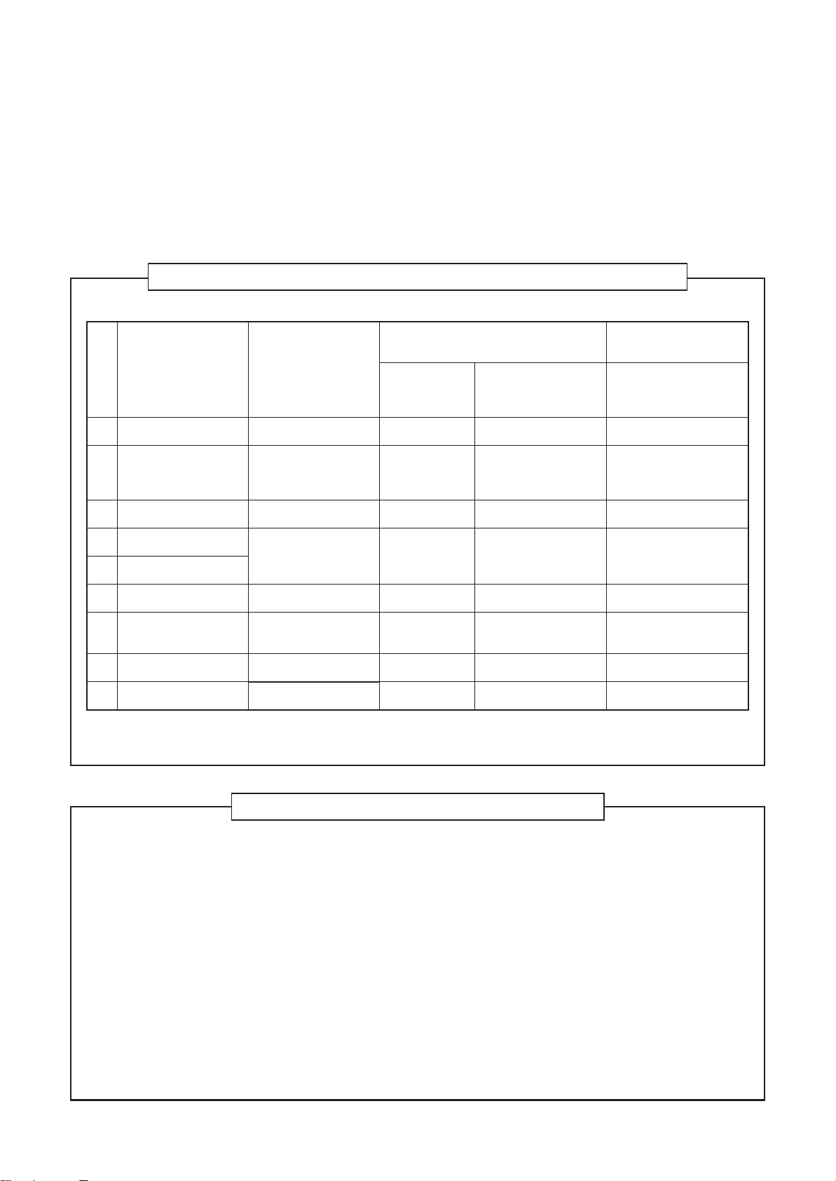
Definition of Protective Gear
When the air conditioner is to be transported, installed, maintained, repaired or removed, wear protective
gloves and ‘safety’ work clothing.
In addition to such normal protective gear, wear the protective gear described below when undertaking the
special work detailed in the table below.
Failure to wear the proper protective gear is dangerous because you will be more susceptible to injury, burns,
electric shocks and other injuries.
Work undertaken
All types of work
Electrical-related work
Work done at heights (50 cm or more)
Transportation of heavy objects
Repair of outdoor unit
Protective gloves
“Safety” working clothing
Gloves to provide protection for electricians and from heat
Insulating shoes
Clothing to provide protection from electric shock
Helmets for use in industry
Shoes with additional protective toe cap
Gloves to provide protection for electricians and from heat
Protective gear worn
The important contents concerned to the safety are described on the product itself and on this Service Manual.
Please read this Service Manual after understanding the described items thoroughly in the following contents
(Indications/Illustrated marks), and keep them.
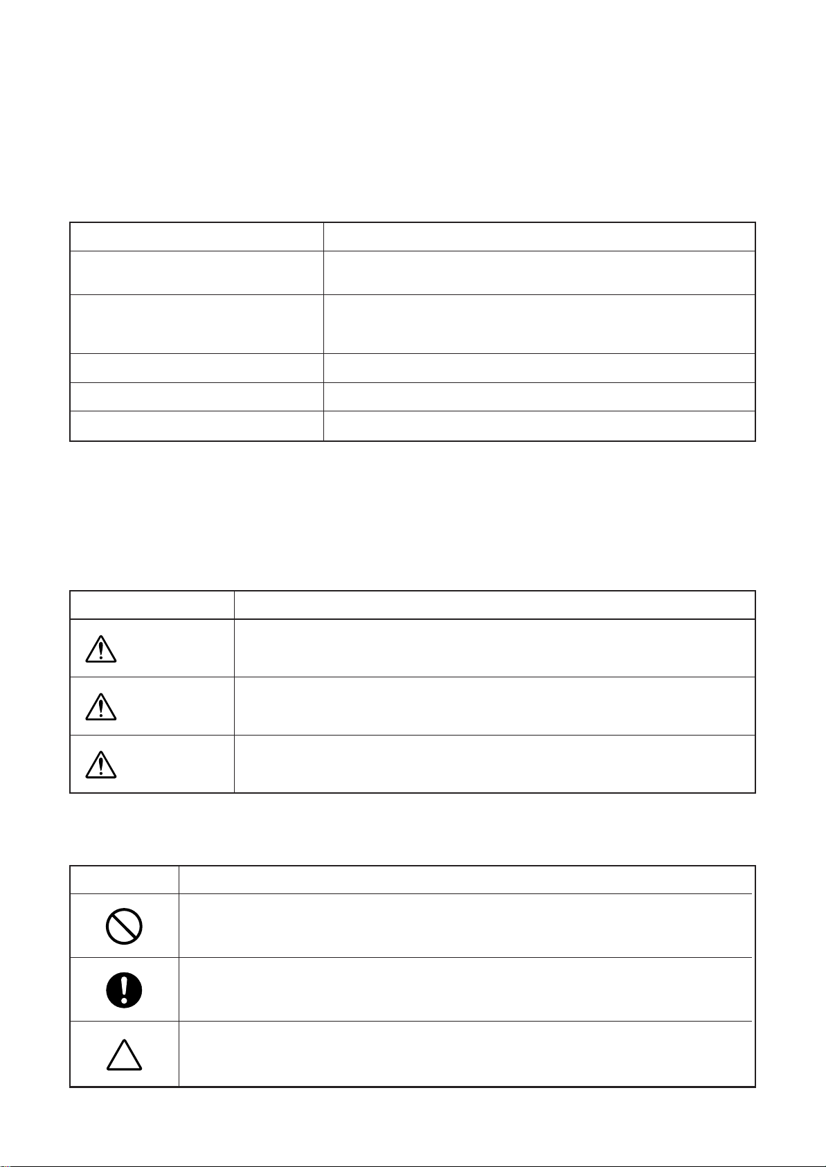
[Explanation of indications]
Indication
Explanation
DANGER
WARNING
CAUTION
Indicates contents assumed that an imminent danger causing a death or serious injury of
the repair engineers and the third parties when an incorrect work has been executed.
Indicates possibilities assumed that a danger causing a death or serious injury of the
repair engineers, the third parties, and the users due to troubles of the product after work
when an incorrect work has been executed.
Indicates contents assumed that an injury or property damage (∗) may be caused on the
repair engineers, the third parties, and the users due to troubles of the product after work
when an incorrect work has been executed.
∗ Property damage : Enlarged damage concerned to property, furniture, and domestic animal/pet
[Explanation of illustrated marks]
Mark Explanation
Indicates prohibited items (Forbidden items to do)
The sentences near an illustrated mark describe the concrete prohibited contents.
Indicates mandatory items (Compulsory items to do)
The sentences near an illustrated mark describe the concrete mandatory contents.
Indicates cautions (Including danger/warning)
The sentences or illustration near or in an illustrated mark describe the concrete cautious contents.
– 5 –
Page 6
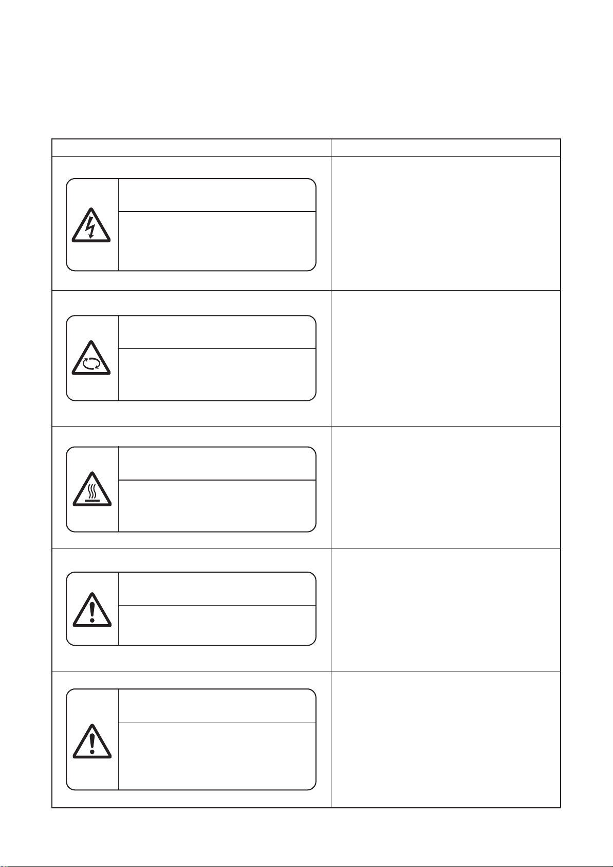
Warning Indications on the Air Conditioner Unit
[Confirmation of warning label on the main unit]
Confirm that labels are indicated on the specified positions
If removing the label during parts replace, stick it as the original.
Warning indication
WARNING
ELECTRICAL SHOCK HAZARD
Disconnect all remote electric
power supplies before servicing.
WARNING
Moving parts.
Do not operate unit with grille removed.
Stop the unit before the servicing.
Description
WARNING
ELECTRICAL SHOCK HAZARD
Disconnect all remote electric power supplies
before servicing.
WARNING
Moving parts.
Do not operate unit with grille removed.
Stop the unit before the servicing.
CAUTION
High temperature parts.
You might get burned when removing
this panel.
CAUTION
Do not touch the aluminum fins of the unit.
Doing so may result in injury.
CAUTION
BURST HAZARD
Open the service valves before the
operation, otherwise there might be the
burst.
CAUTION
High temperature parts.
You might get burned when removing this panel.
CAUTION
Do not touch the aluminum fins of the unit.
Doing so may result in injury.
CAUTION
BURST HAZARD
Open the service valves before the operation,
otherwise there might be the burst.
– 6 –
Page 7
Precaution for Safety
The manufacturer shall not assume any liability for the damage caused by not observing the description of this
manual.
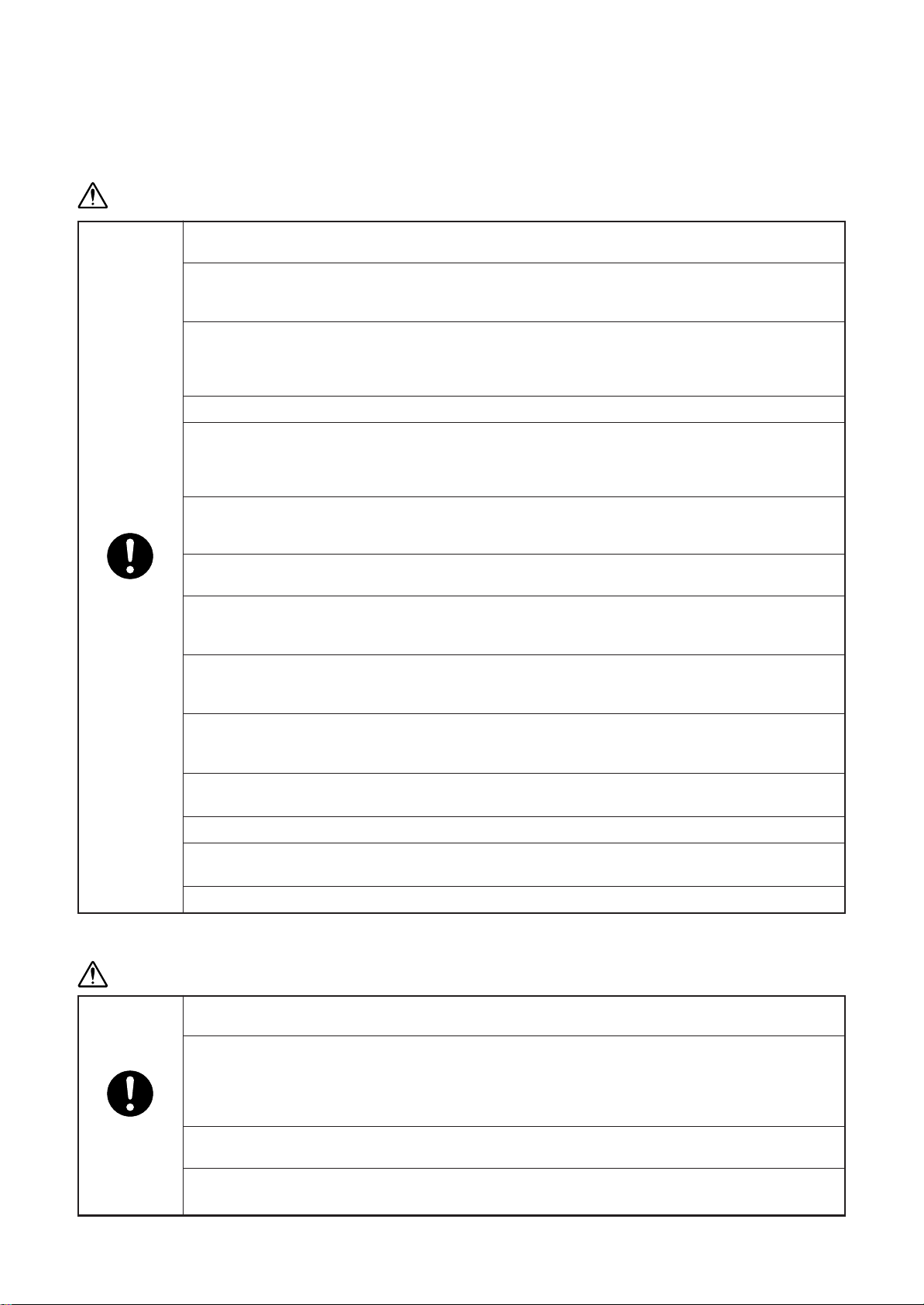
WARNING
Before starting to repair the air conditioner, read carefully through the Service Manual, and repair
the air conditioner by following its instructions.
Only qualified service person (∗1) is allowed to repair the air conditioner.
Repair of the air conditioner by unqualified person may give rise to a fire, electric shocks, injury,
water leaks and/or other problems.
Only a qualified installer (∗1) or qualified service person (∗1) is allowed to carry out the electrical
work of the air conditioner.
Under no circumstances must this work be done by an unqualified individual since failure to carry
out the work properly may result in electric shocks and/or electrical leaks.
Wear protective gloves and safety work clothing during installation, servicing and removal.
When connecting the electrical wires, repairing the electrical parts or undertaking other electrical
jobs, wear gloves to provide protection for electricians and from heat, insulating shoes and
clothing to provide protection from electric shocks.
Failure to wear this protective gear may result in electric shocks.
Use wiring that meets the specifications in the Installation Manual and the stipulations in the local
regulations and laws. Use of wiring which does not meet the specifications may give rise to
electric shocks, electrical leakage, smoking and/or a fire.
Only a qualified installer (∗1) or qualified service person (∗1) is allowed to undertake work at heights
General
using a stand of 50 cm or more or to remove the intake grille of the indoor unit to undertake work.
When working at heights, use a ladder which complies with the ISO 14122 standard, and follow
the procedure in the ladder’s instructions.
Also wear a helmet for use in industry as protective gear to undertake the work.
When working at heights, put a sign in place so that no-one will approach the work location,
before proceeding with the work.
Parts and other objects may fall from above, possibly injuring a person below.
Do not touch the aluminum fin of the outdoor unit.
You may injure yourself if you do so. If the fin must be touched for some reason, first put on
protective gloves and safety work clothing, and then proceed.
Do not climb onto or place objects on top of the outdoor unit.
You may fall or the objects may fall off of the outdoor unit and result in injury.
When transporting the air conditioner, wear shoes with additional protective toe caps.
When transporting the air conditioner, do not take hold of the bands around the packing carton.
You may injure yourself if the bands should break.
This air conditioner has passed the pressure test as specified in IEC 60335-2-40 Annex EE.
DENGER
Before carrying out the installation, maintenance, repair or removal work, be sure to set the circuit
breaker to the OFF position. Otherwise, electric shocks may result.
Before opening the intake grille of the indoor unit or service panel of the outdoor unit, set the
circuit breaker to the OFF position. Failure to set the circuit breaker to the OFF position may result
in electric shocks through contact with the interior parts.
Only a qualified installer (∗1) or qualified service person (∗1) is allowed to remove the intake grille
of the indoor unit or service panel of the outdoor unit and do the work required.
Turn off
breaker.
Before starting to repair the outdoor unit fan or fan guard, be absolutely sure to set the circuit
breaker to the OFF position, and place a “Work in progress” sign on the circuit breaker.
When cleaning the filter or other parts of the indoor unit, set the circuit breaker to OFF without
fail, and place a “Work in progress” sign near the circuit breaker before proceeding with the work.
– 7 –
Page 8
Execute
discharge
between
terminals.
Prohibition
Stay on
protection
WARNING
Check earth
wires.
Even if the circuit breaker has been set to the OFF position before the service panel is removed
and the electrical parts are repaired, you will still risk receiving an electric shock.
For this reason, short-circuit the high-voltage capacitor terminals to discharge the voltage before
proceeding with the repair work.
For details on the short-circuiting procedure, refer to the Service Manual.
You may receive an electric shock if the voltage stored in the capacitors has not been sufficiently
discharged.
Place a “Work in progress” sign near the circuit breaker while the installation, maintenance, repair
or removal work is being carried out.
There is a danger of electric shocks if the circuit breaker is set to ON by mistake.
If, in the course of carrying out repairs, it becomes absolutely necessary to check out the
electrical parts with the electrical parts box cover of one or more of the indoor units and the
service panel of the outdoor unit removed in order to find out exactly where the trouble lies, wear
insulated heat-resistant gloves, insulated boots and insulated work overalls, and take care to
avoid touching any live parts.
You may receive an electric shock if you fail to heed this warning. Only qualified service person
(∗1) is allowed to do this kind of work.
Before troubleshooting or repair work, check the earth wire is connected to the earth terminals of
the main unit, otherwise an electric shock is caused when a leak occurs.If the earth wire is not
correctly connected, contact an electric engineer for rework.
After completing the repair or relocation work, check that the ground wires are connected properly.
Be sure to connect earth wire. (Grounding work) Incomplete grounding causes an electric shock.
Do not connect ground wires to gas pipes, water pipes, and lightning rods or ground wires for
telephone wires.
Do not modify the products.Do not also disassemble or modify the parts.
It may cause a fire, electric shock or injury.
Prohibition of
modification.
Use specified
parts.
Do not bring
a child close to
the equipment.
Insulating
measures
No fire
When any of the electrical parts are to be replaced, ensure that the replacement parts satisfy the
specifications given in the Service Manual (or use the parts contained on the parts list in the
Service Manual).
Use of any parts which do not satisfy the required specifications may give rise to electric shocks,
smoking and/or a fire.
If, in the course of carrying out repairs, it becomes absolutely necessary to check out the
electrical parts with the electrical parts box cover of one or more of the indoor units and the
service panel of the outdoor unit removed in order to find out exactly where the trouble lies, place
"Keep out" signs around the work site before proceeding.
Third-party individuals may enter the work site and receive electric shocks if this warning is not
heeded.
Connect the cut-off lead wires with crimp contact, etc, put the closed end side upward and then
apply a water-cut method, otherwise a leak or production of fire is caused at the users’ side.
When performing repairs using a gas burner, replace the refrigerant with nitrogen gas because
the oil that coats the pipes may otherwise burn.
When repairing the refrigerating cycle, take the following measures.
1) Be attentive to fire around the cycle.
When using a gas stove, etc, be sure to put out fire before work; otherwise the oil mixed with
refrigerant gas may catch fire.
2) Do not use a welder in the closed room.
When using it without ventilation, carbon monoxide poisoning may be caused.
3) Do not bring inflammables close to the refrigerant cycle, otherwise fire of the welder may catch
the inflammables.
– 8 –
Page 9
Refrigerant
Assembly/
Cabling
Insulator
check
Ventilation
Compulsion
The refrigerant used by this air conditioner is the R410A.
Check the used refrigerant name and use tools and materials of the parts which match with it.
For the products which use R410A refrigerant, the refrigerant name is indicated at a position on
the outdoor unit where is easy to see.
To prevent miss-charging, the route of the service port is changed from one of the former R22.
Do not use any refrigerant different from the one specified for complement or replacement.
Otherwise, abnormally high pressure may be generated in the refrigeration cycle, which may
result in a failure or explosion of the product or an injury to your body.
For an air conditioner which uses R410A, never use other refrigerant than R410A.
For an air conditioner which uses other refrigerant (R22, etc.), never use R410A.
If different types of refrigerant are mixed, abnormal high pressure generates in the refrigerating
cycle and an injury due to breakage may be caused.
Do not charge refrigerant additionally.
If charging refrigerant additionally when refrigerant gas leaks, the refrigerant composition in the
refrigerating cycle changes resulted in change of air conditioner characteristics or refrigerant over
the specified standard amount is charged and an abnormal high pressure is applied to the inside
of the refrigerating cycle resulted in cause of breakage or injury.
Therefore if the refrigerant gas leaks, recover the refrigerant in the air conditioner, execute
vacuuming, and then newly recharge the specified amount of liquid refrigerant.
In this time, never charge the refrigerant over the specified amount.
When recharging the refrigerant in the refrigerating cycle, do not mix the refrigerant or air other
than R410A into the specified refrigerant.
If air or others is mixed with the refrigerant, abnormal high pressure generates in the refrigerating
cycle resulted in cause of injury due to breakage.
After installation work, check the refrigerant gas does not leak.
If the refrigerant gas leaks in the room, poisonous gas generates when gas touches to fire such
as fan heater, stove or cocking stove though the refrigerant gas itself is innocuous.
Never recover the refrigerant into the outdoor unit.
When the equipment is moved or repaired, be sure to recover the refrigerant with recovering device.
The refrigerant cannot be recovered in the outdoor unit; otherwise a serious accident such as
breakage or injury is caused.
After repair work, surely assemble the disassembled parts, and connect and lead the removed
wires as before.
Perform the work so that the cabinet or panel does not catch the inner wires.
If incorrect assembly or incorrect wire connection was done, a disaster such as a leak or fire is
caused at user’s side.
After the work has finished, be sure to use an insulation tester set (500V Megger) to check the
resistance is 1MΩ or more between the charge section and the non-charge metal section
(Earth position).
If the resistance value is low, a disaster such as a leak or electric shock is caused at user’s side.
When the refrigerant gas leaks during work, execute ventilation.
If the refrigerant gas touches to a fire, poisonous gas generates.
A case of leakage of the refrigerant and the closed room full with gas is dangerous because a
shortage of oxygen occurs. Be sure to execute ventilation.
When the refrigerant gas leaks, find up the leaked position and repair it surely.
If the leaked position cannot be found up and the repair work is interrupted, pump-down and
tighten the service valve, otherwise the refrigerant gas may leak into the room.
The poisonous gas generates when gas touches to fire such as fan heater, stove or cocking stove
though the refrigerant gas itself is innocuous.
When installing equipment which includes a large amount of charged refrigerant such as a multi
air conditioner in a sub-room, it is necessary that the density does not the limit even if the
refrigerant leaks.
If the refrigerant leaks and exceeds the limit density, an accident of shortage of oxygen is caused.
Tighten the flare nut with a torque wrench in the specified manner.
Excessive tighten of the flare nut may cause a crack in the flare nut after a long period, which may
result in refrigerant leakage.
Nitrogen gas must be used for the airtight test.
The charge hose must be connected in such a way that it is not slack.
For the installation/moving/reinstallation work, follow to the Installation Manual.
If an incorrect installation is done, a trouble of the refrigerating cycle, water leak, electric shock or
fire is caused.
– 9 –
Page 10
Check after
repair
Do not
operate the
unit with the
valve closed.
Check after
reinstallation
Cooling check
Installation
Once the repair work has been completed, check for refrigerant leaks, and check the insulation
resistance and water drainage.
Then perform a trial run to check that the air conditioner is running properly.
After repair work has finished, check there is no trouble. If check is not executed, a fire, electric
shock or injury may be caused. For a check, turn off the power breaker.
After repair work (installation of front panel and cabinet) has finished, execute a test run to check
there is no generation of smoke or abnormal sound.
If check is not executed, a fire or an electric shock is caused. Before test run, install the front
panel and cabinet.
Check the following matters before a test run after repairing piping.
• Connect the pipes surely and there is no leak of refrigerant.
• The valve is opened.
Running the compressor under condition that the valve closes causes an abnormal high
pressure resulted in damage of the parts of the compressor and etc. and moreover if there is
leak of refrigerant at connecting section of pipes, the air is suctioned and causes further
abnormal high pressure resulted in burst or injury.
Only a qualified installer (∗1) or qualified service person (∗1) is allowed to relocate the air
conditioner. It is dangerous for the air conditioner to be relocated by an unqualified individual
since a fire, electric shocks, injury, water leakage, noise and/or vibration may result.
Check the following items after reinstallation.
1) The earth wire is correctly connected.
2) The power cord is not caught in the product.
3) There is no inclination or unsteadiness and the installation is stable.
If check is not executed, a fire, an electric shock or an injury is caused.
When carrying out the pump-down work shut down the compressor before disconnecting the
refrigerant pipe.
Disconnecting the refrigerant pipe with the service valve left open and the compressor still
operating will cause air, etc. to be sucked in, raising the pressure inside the refrigeration cycle to
an abnormally high level, and possibly resulting in reputing, injury, etc.
When the service panel of the outdoor unit is to be opened in order for the compressor or the
area around this part to be repaired immediately after the air conditioner has been shut down, set
the circuit breaker to the OFF position, and then wait at least 10 minutes before opening the
service panel.
If you fail to heed this warning, you will run the risk of burning yourself because the compressor
pipes and other parts will be very hot to the touch. In addition, before proceeding with the repair
work, wear the kind of insulated heat-resistant gloves designed to protect electricians.
When the service panel of the outdoor unit is to be opened in order for the fan motor, reactor,
inverter or the areas around these parts to be repaired immediately after the air conditioner has
been shut down, set the circuit breaker to the OFF position, and then wait at least 10 minutes
before opening the service panel.
If you fail to heed this warning, you will run the risk of burning yourself because the fan motor,
reactor, inverter heat sink and other parts will be very hot to the touch.
In addition, before proceeding with the repair work, wear the kind of insulated heat-resistant
gloves designed to protect electricians.
Only a qualified installer (∗1) or qualified service person (∗1) is allowed to install the air
conditioner. If the air conditioner is installed by an unqualified individual, a fire, electric shocks,
injury, water leakage, noise and/or vibration may result.
Before starting to install the air conditioner, read carefully through the Installation Manual, and
follow its instructions to install the air conditioner.
Do not install the air conditioner in a location that may be subject to a risk of expire to a
combustible gas.
If a combustible gas leaks and becomes concentrated around the unit, a fire may occur.
Install the indoor unit at least 2.5 m above the floor level since otherwise the users may injure
themselves or receive electric shocks if they poke their fingers or other objects into the indoor unit
while the air conditioner is running.
Install a circuit breaker that meets the specifications in the installation manual and the stipulations
in the local regulations and laws.
Install the circuit breaker where it can be easily accessed by the qualified service person (∗1).
Do not place any combustion appliance in a place where it is directly exposed to the wind of air
conditioner, otherwise it may cause imperfect combustion.
– 10 –
Page 11

Explanations given to user
• If you have discovered that the fan grille is damaged, do not approach the outdoor unit but set the circuit
breaker to the OFF position, and contact a qualified service person to have the repairs done. Do not set the
circuit breaker to the ON position until the repairs are completed.
Relocation
• Only a qualified installer (∗1) or qualified service person (∗1) is allowed to relocate the air conditioner.
It is dangerous for the air conditioner to be relocated by an unqualified individual since a fire, electric shocks,
injury, water leakage, noise and/or vibration may result.
• When carrying out the pump-down work shut down the compressor before disconnecting the refrigerant pipe.
Disconnecting the refrigerant pipe with the service valve left open and the compressor still operating will
cause air, etc. to be sucked in, raising the pressure inside the refrigeration cycle to an abnormally high level,
and possibly resulting in reputing, injury, etc.
(∗1) Refer to the “Definition of Qualified Installer or Qualified Service Person.”
Declaration of Conformity
Manufacturer: Toshiba Carrier Corporation
336 Tadehara, Fuji-shi, Shizuoka-ken 416-8521 JAPAN
Authorized Nick Ball
Representative/TCF holder: Toshiba EMEA Engineering Director
Toshiba Carrier UK Ltd.
Porsham Close, Belliver Industrial Estate,
PLYMOUTH, Devon, PL6 7DB.
United Kingdom
Hereby declares that the machinery described below:
Generic Denomination: Air Conditioner
Model/type: RAV-SM404MUT-E RAV-SM404MUT-TR
RAV-SM454MUT-E RAV-SM454MUT-TR
RAV-SM564MUT-E RAV-SM564MUT-TR
RAV-SM564BT-E RAV-SM564BT-TR
RAV-SM804BT-E RAV-SM804BT-TR
RAV-SM1104BT-E RAV-SM1104BT-TR
RAV-SM1404BT-E RAV-SM1404BT-TR
RAV-SM564CT-E RAV-SM564CT-TR
RAV-SM804CT-E RAV-SM804CT-TR
RAV-SM1104CT-E RAV-SM1104CT-TR
RAV-SM1404CT-E RAV-SM1404CT-TR
Commercial name: Digital Inverter Series / Super Digital Inverter Series Air Conditioner
Complies with the provisions of the “Machinery” Directive (Directive 2006/42/EC) and the regulations
transposing into national law.
Complies with the provisions of the following harmonized standard:
EN 378-2: 2008 / A1: 2009
Note: This declaration becomes invalid if technical or operational modifications are introduced without the
manufacturer’s consent.
– 11 –
Page 12

Specifications
Model
RAV-SM404MUT-E
RAV-SM454MUT-E
RAV-SM564MUT-E
RAV-SM404MUT-TR
RAV-SM454MUT-TR
RAV-SM564MUT-TR
RAV-SM564BT-E
RAV-SM804BT-E
RAV-SM1104BT-E
RAV-SM1404BT-E
RAV-SM564BT-TR
RAV-SM804BT-TR
Sound power level (dBA)
Cooling Heating
∗∗
∗∗
∗∗
∗∗
∗∗
∗∗
∗∗
∗∗
∗∗
∗∗
∗∗
∗∗
Weight (kg)
Main unit (Ceiling panel)
16 (3)
16 (3)
16 (3)
16 (3)
16 (3)
16 (3)
30
39
54
54
30
39
RAV-SM1104BT-TR
RAV-SM1404BT-TR
RAV-SM564CT-E
RAV-SM804CT-E
RAV-SM1104CT-E
RAV-SM1404CT-E
RAV-SM564CT-TR
RAV-SM804CT-TR
RAV-SM1104CT-TR
RAV-SM1404CT-TR
: Under 70 dBA
∗
• Other specifications than abovementioned models are equal to current models (2 series).
∗∗
∗∗
∗∗
∗∗
∗∗
∗∗
∗∗
∗∗
∗∗
∗∗
54
54
21
25
33
33
21
25
33
33
– 12 –
Page 13

New Refrigerant (R410A)
This air conditioner adopts a new HFC type refrigerant (R410A) which does not deplete the ozone layer.
1. Safety Caution Concerned to New Refrigerant
The pressure of R410A is high 1.6 times of that of the former refrigerant (R22).
Accompanied with change of refrigerant, the refrigerating oil has been also changed.
Therefore, be sure that water, dust, the former refrigerant or the former refrigerating oil is not mixed into the
refrigerating cycle of the air conditioner with new refrigerant during installation work or service work.
If an incorrect work or incorrect service is performed, there is a possibility to cause a serious accident.
Use the tools and materials exclusive to R410A to purpose a safe work.
2. Cautions on Installation/Service
1) Do not mix the other refrigerant or refrigerating oil.
For the tools exclusive to R410A, shapes of all the joints including the service port differ from those of
the former refrigerant in order to prevent mixture of them.
2) As the use pressure of the new refrigerant is high, use material thickness of the pipe and tools which are
specified for R410A.
3) In the installation time, use clean pipe materials and work with great attention so that water and others
do not mix in because pipes are affected by impurities such as water, oxide scales, oil, etc.
Use the clean pipes.
Be sure to brazing with flowing nitrogen gas. (Never use gas other than nitrogen gas.)
4) For the earth protection, use a vacuum pump for air purge.
5) R410A refrigerant is azeotropic mixture type refrigerant.
Therefore use liquid type to charge the refrigerant. (If using gas for charging, composition of the
refrigerant changes and then characteristics of the air conditioner change.)
3. Pipe Materials
For the refrigerant pipes, copper pipe and joints are mainly used.
It is necessary to select the most appropriate pipes to conform to the standard.
Use clean material in which impurities adhere inside of pipe or joint to a minimum.
1) Copper pipe
<Piping>
The pipe thickness, flare finishing size, flare nut and others differ according to a refrigerant type.
When using a long copper pipe for R410A, it is recommended to select “Copper or copper-base pipe
without seam” and one with bonded oil amount 40mg/10m or less.
Also do not use crushed, deformed, discolored (especially inside) pipes.
(Impurities cause clogging of expansion valves and capillary tubes.)
<Flare nut>
Use the flare nuts which are attached to the air conditioner unit.
2) Joint
The flare joint and socket joint are used for joints of the copper pipe.
The joints are rarely used for installation of the air conditioner.
However clear impurities when using them.
– 13 –
Page 14
4. Tools
1. Required Tools for R410A
Mixing of different types of oil may cause a trouble such as generation of sludge, clogging of capillary,
etc. Accordingly, the tools to be used are classified into the following three types.
1) Tools exclusive for R410A (Those which cannot be used for conventional refrigerant (R22))
2) Tools exclusive for R410A, but can be also used for conventional refrigerant (R22)
3) Tools commonly used for R410A and for conventional refrigerant (R22)
The table below shows the tools exclusive for R410A and their interchangeability.
Tools exclusive for R410A (The following tools for R410A are required.)
Tools whose specifications are changed for R410A and their interchangeability
No.
Q
R
S
T
U
V
W
X
Y
Used tool
Flare tool
Copper pipe gauge
for adjusting
projection margin
Torque wrench
Gauge manifold
Charge hose
Vacuum pump adapter
Electronic balance for
refrigerant charging
Refrigerant cylinder
Leakage detector
Usage
Pipe flaring
Flaring by
conventional flare tool
Tightening of flare nut
Evacuating, refrigerant
charge, run check, etc.
Vacuum evacuating
Refrigerant charge
Refrigerant charge
Gas leakage check
air conditioner installation
Existence of
new equipment
for R410A
Ye s ∗ (Note)
Ye s ∗ (Note)
Ye s N o
Ye s N o
Ye s N o
Ye s Ye s
Ye s N o
Ye s N o
R410A
Whether conventional
equipment can be used
Conventional air
conditioner installation
Whether
conventional equipment
can be used
Ye s
∗ (Note)
No
No
Ye s
Ye s
No
Ye s
(Note) When flaring is carried out for R410A using the conventional flare tools, adjustment of projection
margin is necessary. For this adjustment, a copper pipe gauge, etc. are necessary.
General tools (Conventional tools can be used.)
In addition to the above exclusive tools, the following equipments which serve also for R22 are necessary
as the general tools.
1) Vacuum pump. Use vacuum pump by
attaching vacuum pump adapter. 7) Screwdriver (+, –)
2) Torque wrench 8) Spanner or Monkey wrench
3) Pipe cutter 9) Hole core drill
4) Reamer 10) Hexagon wrench (Opposite side 4mm)
5) Pipe bender 11) Tape measure
6) Level vial 12) Metal saw
Also prepare the following equipments for other installation method and run check.
1) Clamp meter 3) Insulation resistance tester (Megger)
2) Thermometer 4) Electroscope
– 14 –
Page 15
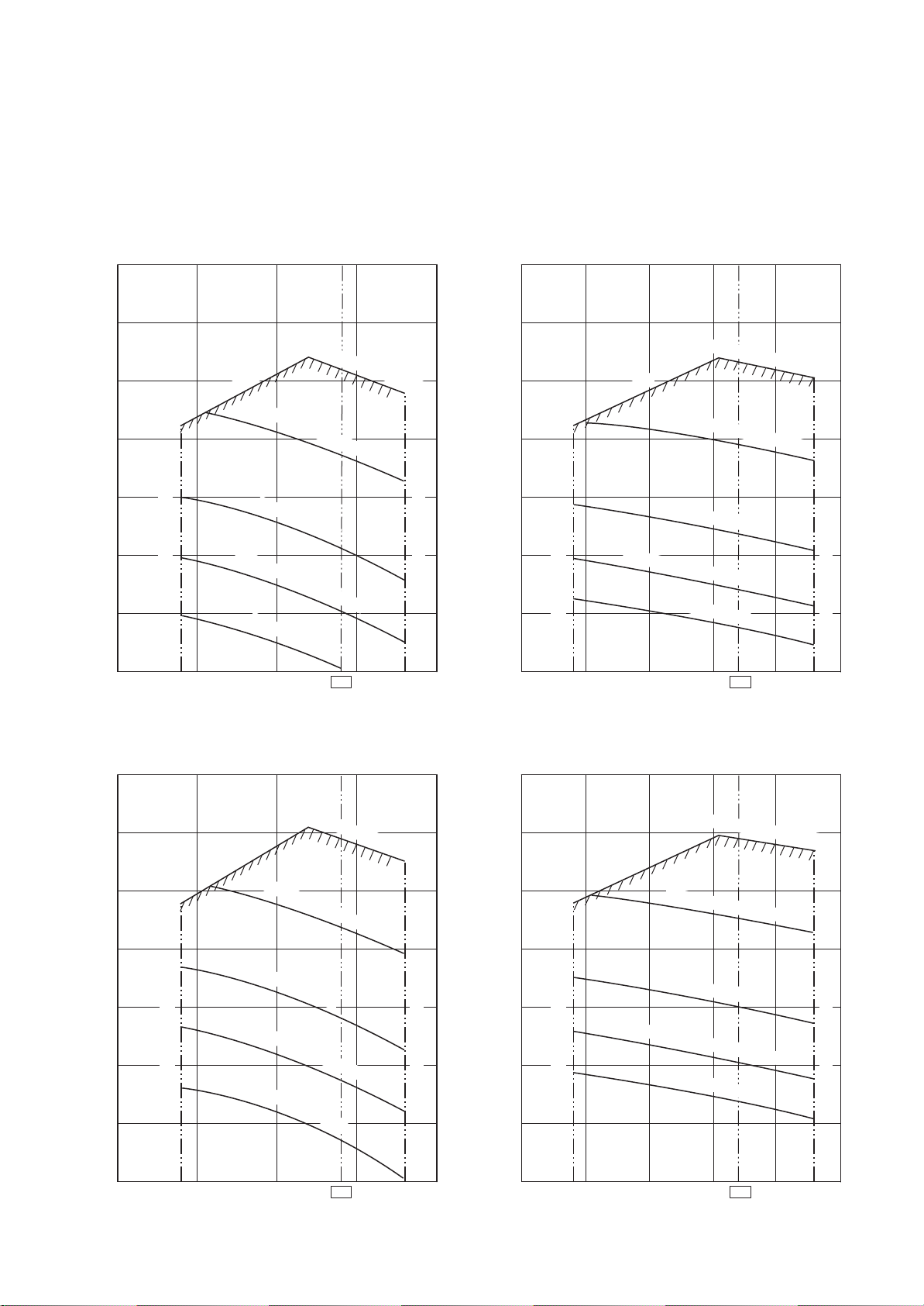
1. AIR DUCTING WORK
1-1. Static Pressure Characteristics
Concealed Duct type
RAV-SN564BT
∗∗
, RAV-SN804BT
∗
∗∗
∗∗
, RAV-SN1104BT
∗
∗∗
∗∗
, RAV-SN1404BT
∗
∗∗
∗∗
∗
∗∗
Fig. 1 SM56 type (Round duct)
140
120
100
Usable limit
80
60
Static pressure (Pa)
40
Air volume limit (Min.)
20
Standard air volume 780m³/h
High static pressure 2H tap
High static pressure 1H tap
Standard H tap
Lo
w static pressure H ta
Standard L tap
140
120
100
Static pressure (Pa)
Air volume limit (Max.)
p
Fig. 3 SM80 type (Round duct)
Standard air volume 1140m³/h
Usable limit
80
60
40
20
Air volume limit (Min.)
High static pressure 1H tap
Standard H tap
Low static pressure H tap
Standard L
High static pressure 2H tap
tap
Air volume limit (Max.)
0
500 700 780
Air volume m³/h
Fig. 2 SM56 type (Square duct)
140
120
108
100
80
60
Static pressure (Pa)
40
20
Usable limit
Air volume limit (Min.)
Standard air volume 780m³/h
High static pressure 2H tap
High static press
Standard H tap
Low static pressure H tap
Standard L tap
ure 1H tap
900
Air volume limit (Max.)
0
800 1000
140
120
100
80
60
Static pressure (Pa)
40
20
12001140 1300
Air volume m³/h
Fig. 4 SM80 type (Square duct)
Standard air volume 1140m³/h
High static pressure 2H tap
Usable limit
Air volume limit (Min.)
High static pressure 1H tap
Standard H tap
Low static pressure H tap
Standard L tap
Air volume limit (Max.)
0
500 700 780
Air volume m³/h
900
– 15 –
0
800 1000
Air volume m³/h
12001140 1300
Page 16

0
Fig. 5 SM110 type (Round duct)
Fig. 7 SM140 type (Round duct)
140
120
Standard air volume 1620m³/h
140
120
Standard air volume 1980m³/h
High static pressure 2H tap
High static pressure 2H tap
100
100
Usable limit
High static pressure 1H tap
80
60
Standard H tap
Static pressure (Pa)
40
Air volume limit (Min.)
20
0
1200
Low static pressure H tap
Standard L tap
1620
Air volume limit (Max.)
2000
80
60
Static pressure (Pa)
40
20
0
1200 1800
Air volume m³/h
Usable limit
Air volume limit (Min.)
High static pressure 1H tap
Standard H tap
Low static pressure H tap
Standard L tap
1980
Air volume m³/h
Air volume limit (Max.)
2200 2400
Fig. 6 SM110 type (Square duct)
140
Standard air volume 1620m³/h
Fig. 8 SM140 type (Square duct)
140
Standard air volume 1980m³/h
High static pressure 2H tap
120
120
High static pressure 2H tap
Usable limit
100
80
High static pressure 1H tap
100
80
Standard H tap
60
Static pressure (Pa)
40
Air volume limit (Min.)
Low static pressure H tap
Air volume limit (Max.)
60
Static pressure (Pa)
40
Standard L tap
20
20
Usable limit
Air volume limit (Min.)
High static pressure 1H tap
Standard H tap
Low static pressure H tap
Standard L tap
Air volume limit (Max.)
0
1200
1620
Air volume m³/h
2000
– 16 –
0
1200 1800
Air volume hm³/h
1980
2200 240
Page 17
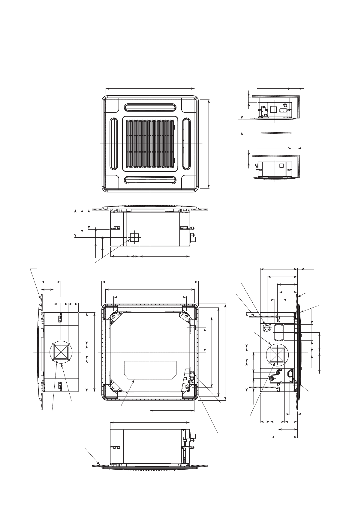
2. CONSTRUCTION VIEWS (EXTERNAL VIEWS)
2-1. Compact 4-way Cassette Type
RAV-SM404MUT
, RAV-SM454MUT
∗∗
∗
∗∗
149
175
207
, RAV-SM564MUT
∗∗
∗
∗∗
595 to 660 Ceiling open dimension
∗∗
∗
∗∗
595 to 660 Ceiling open dimension
1000 or more
15 or more15 or more
1000 or more
Obustacle
1000 or more
Space required for
installation and servicing
Bottom face
of ceiling
145.5
93
105
For branch duct knockout
square hole Ø150
Knockout for flesh
air intake Ø100
70
235
105235
Ø162
Bottom face of ceiling
64
575 Unit external dimension
142 64
29
700 Panel external dimension
595 to 660 Ceiling open dimension
525 Hanging bolt pitch
Electric parts box
575 Unit external dimension
368.5
320.5
Drain discharge port
Hanging bolt
M10 or W3/8
local arrange
Ø162
256
177
148
510 Hanging bolt pitch
700 Panel external dimension
595 to 660 Ceiling open dimension
Refrigerant pipe
(Liquid) Ø6.4
For branch ductt
knockout square
hole Ø150
Refrigerant pipe
(Gas) Ø12.7
214 105
97.5 42
268 27
220.5
145.5
134
63
9310570
139.5
190.5
Bottom face
of ceiling
Ceiling panel
55
120
142
21
158
Wiring
connection
port
– 17 –
Page 18
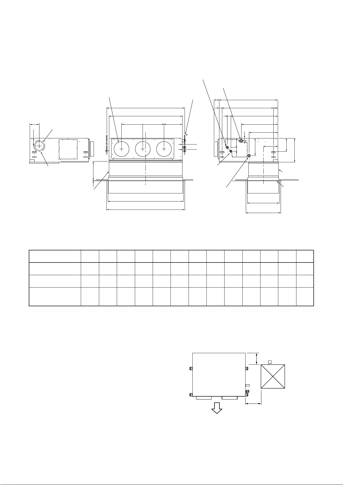
2-2. Concealed Duct Type
RAV-SM564BT
129
110
Knock-out hole Ø125
(Air take-in port)
6-Ø4 Tapping screw
undersized hole Ø160
Suction port canvas
(Separate sold)
, RAV-SM804BT
∗∗
∗
∗∗
Discharge port flange
N-Ø200
60 to 260
9
, RAV-SM1104BT
∗∗
∗
∗∗
Refrigerant pipe connecting port
(Gas side ØF)
Hanging bolt pitch B
Main unit dimension A
J = M x K H
C
Ceiling open size D
Panel external dimension E
, RAV-SM1404BT
∗∗
∗
∗∗
Hanging bolt
4-M10 screw
(Arranged locally)
44
49
Refrigerant pipe
connecting port
(Liquid side ØG)
Ø26 Power supply,
remote controller
cable take-out port
∗∗
∗
∗∗
Drain pipe connecting port
for vinyl chloride pipe
(Inner dia. 32, VP. 25)
75
Main unit dimension 800
Hanging bolt pitch 700
50
638
41
131
50
Ceiling open size
498
393
243
Panel C.L
410
470
Panel external
dimension 500
196
5941
174
Suction port
flange
(Separate sold)
Suction port
panel
(Separate sold)
320
• Dimension
ABCDEFGHJ KMNO
SM56 type
SM80 type
SM110 type
SM140 type
NOTE 1 :
For maintenance of the equipment, be sure to install
a check port A at the position as shown below.
NOTE 2 :
Using the drain up kit sold separately, drain-up by 300 (mm)
from drain pipe draw-out port of the main unit is necessary.
The drain-up over 300mm or more is impossible.
700 766 690 750 780 12.7 6.4 252 280 280 1 2 410
1000 1066 990 1050 1080 15.9 9.5 252 580 290 2 3 410
1350 1416 1340 1400 1430 15.9 9.5 252 930 310 3 4 410
Plane view of main unit
(Pipe side)
Discharge side
Check port A
300
100
450
– 18 –
Page 19
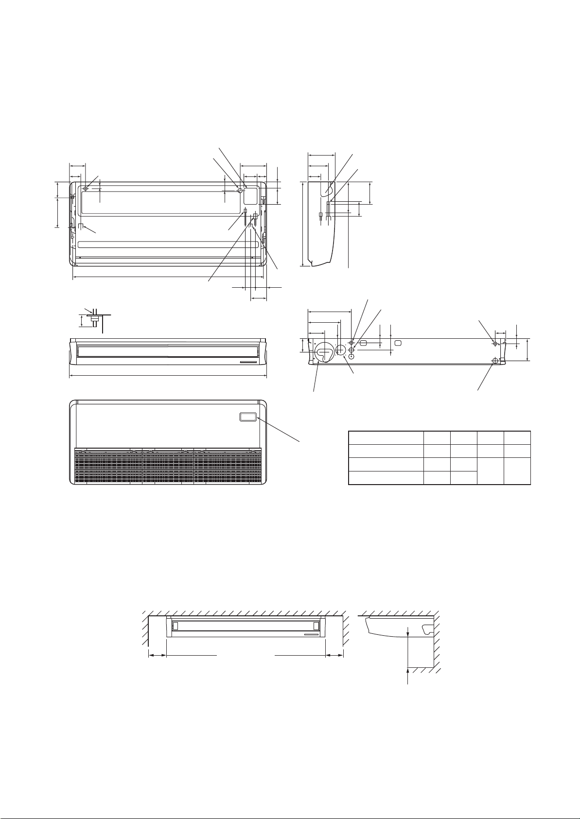
2-3. Ceiling Type
RAV-SM564CT
Power supply cable take-in port (Knockout)
128
Remote controller cable take- in port
(Knockout hole)
84
170320
(Hanging position)
Hanging bolt
50
Within
53
Left drain size
Ceiling surface
Unit
, RAV-SM804CT
∗∗
∗
∗∗
Upper pipe draw-out port (Knockout hole)
B (Hanging position)
Refrigerant pipe (Gas side ØD)
∗∗
∗
∗∗
Refrigerant pipe
(Liquid side ØC)
, RAV-SM1104CT
216 167
110
76
50
70
75 97
130
Drain pipe connecting port
146
, RAV-SM1404CT
∗∗
∗
∗∗
210
105
680
200 (Liquid pipe)
347
262
135 84
90
145
∗∗
∗
∗∗
Pipe draw-out port (Knockout hole)
Drain port VP20
(Inner dia. Ø26, hose attached)
114
41
216 (Gas pipe)
Remote controller cable take- in port
Power supply cable take-in port (Knockout hole)
Remote controller cable take- in port
32
(Knockout hole)
92
32
171
A
Pipe hole on wall (Ø100 hole)
Wireless sensor
mounting section
Outside air take-in port
(Duct sold separately)(Knockout hole Ø92)
Drain left pipe draw-out port (Knockout hole)
Model name A B C D
SM56 type
SM80 type
SM110, 140 type
910
1180
1595
855
1125
1540
Ø6.4 Ø12.7
Ø9.5 Ø15.9
250 or more250 or more
– 19 –
500 or more
Page 20
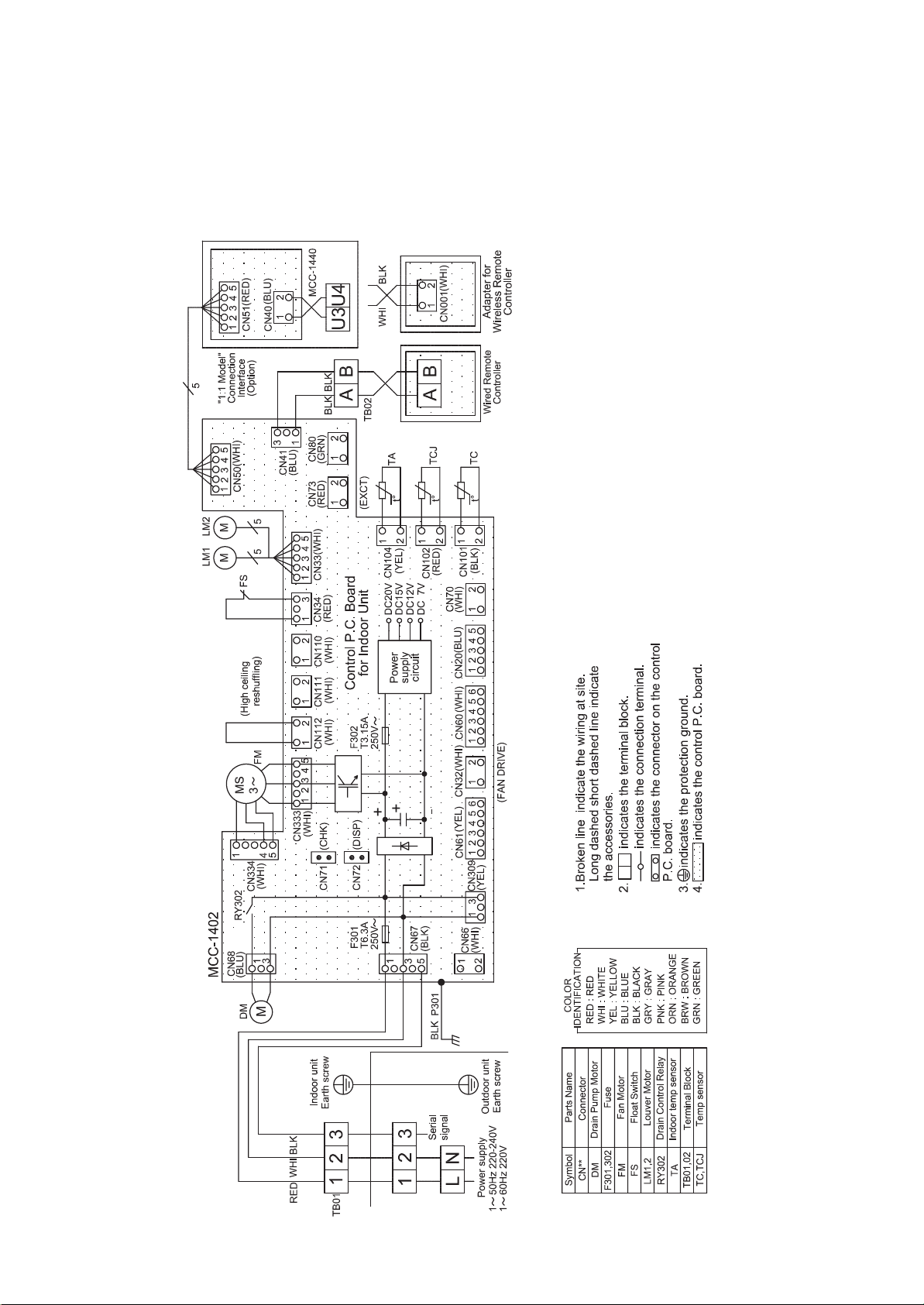
3. WIRING DIAGRAM
3-1. Indoor Unit
3-1-1. Compact 4-way Cassette Type
RAV-SM404MUT
, RAV-SM454MUT
∗∗
∗
∗∗
, RAV-SM564MUT
∗∗
∗
∗∗
∗∗
∗
∗∗
– 20 –
Page 21
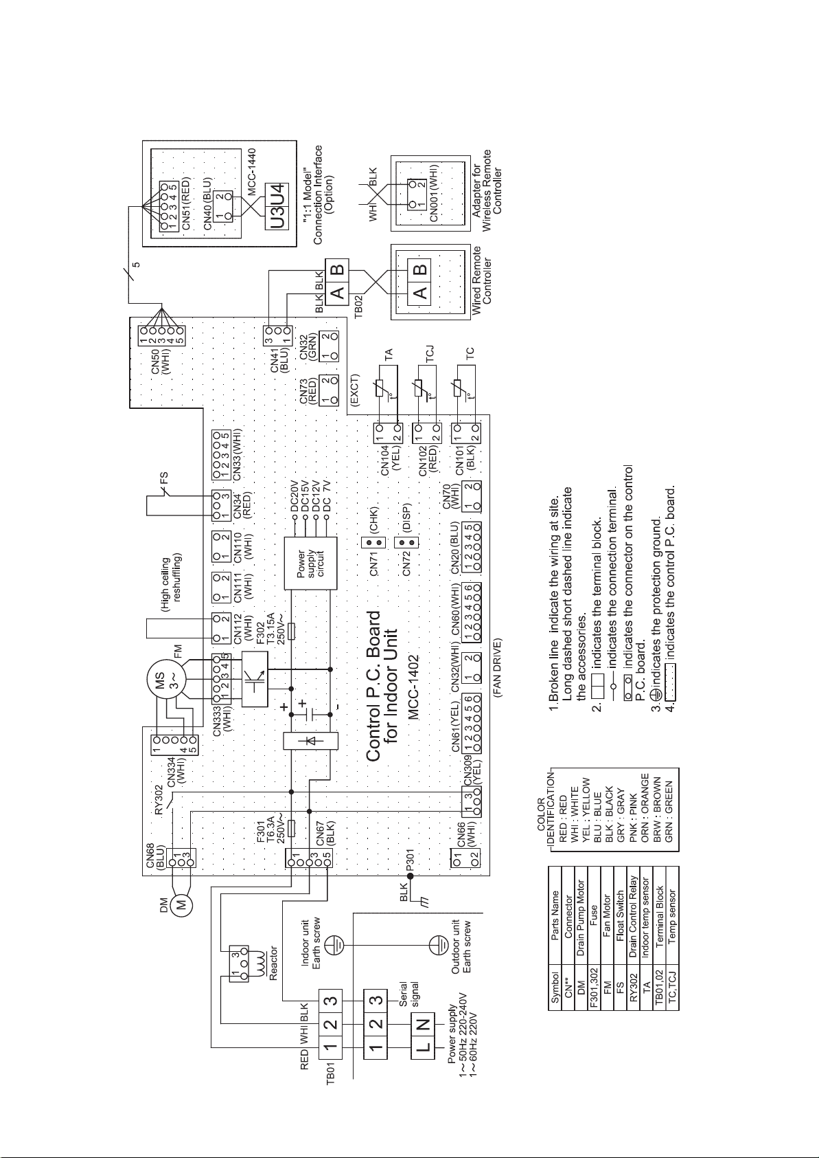
3-1-2. Concealed Duct Type
RAV-SM564BT
, RAV-SM804BT
∗∗
∗
∗∗
, RAV-SM1104BT
∗∗
∗
∗∗
, RAV-SM1404BT
∗∗
∗
∗∗
∗∗
∗
∗∗
– 21 –
Page 22
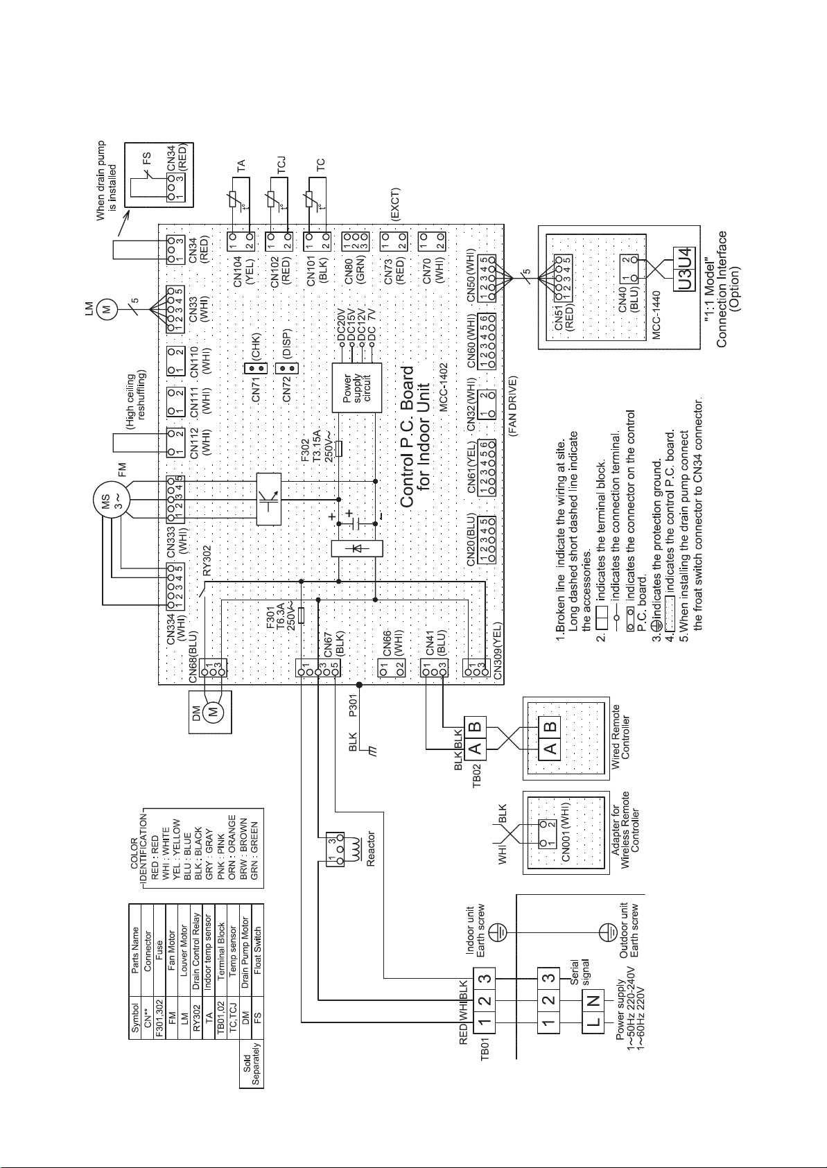
3-1-3. Ceiling Type
RAV-SM564CT
, RAV-SM804CT
∗∗
∗
∗∗
, RAV-SM1104CT
∗∗
∗
∗∗
, RAV-SM1404CT
∗∗
∗
∗∗
∗∗
∗
∗∗
– 22 –
Page 23
4. SPECIFICATIONS OF ELECTRICAL PARTS
4-1. Compact 4-way Cassette Type
No.
1
Fan motor (for indoor)
2
Thermo. sensor (TA-sensor)
3
Heat exchanger sensor (TCJ-sensor)
4
Heat exchanger sensor (TC-sensor)
5
Float switch
6
Drain pump motor
Parts name
4-2. Concealed Duct Type
No.
1
Fan motor (SM804BT)
Fan motor
2
(SM564BT/SM1104BT/SM1404BT)
3
Thermo. sensor (TA-sensor)
Parts name
Type
SWF-230-60-1R
155 mm
Ø6 mm, 1200 mm
Ø6 mm, 1200 mm
FS-0218-102
ADP-1409
Type
ICF-280-120-1C
ICF-280-120-2C
618 mm
Specifications
Output (Rated) 60 W, 220–240 V
10 kΩ at 25°C
10 kΩ at 25°C
10 kΩ at 25°C
Specifications
Output (Rated) 120 W, 220–240 V
Output (Rated) 120 W, 220–240 V
10 kΩ at 25°C
4
Heat exchanger sensor (TCJ-sensor)
5
Heat exchanger sensor (TC-sensor)
6
Float switch
7
Drain pump motor
8
Reactor
4-3. Ceiling Type
No.
1
Fan motor (SM564CT)
2
Fan motor (SM804CT)
3
Fan motor (SM1104CT/SM1404CT)
4
Thermo. sensor (TA-sensor)
5
Heat exchanger sensor (TCJ-sensor)
Parts name
Ø6 mm, 1200 mm
Ø6 mm, 1200 mm
FS-0218-102
ADP-1409
CH-43-2Z-T
Type
SWF-280-60-1R
SWF-280-60-2R
SWF-280-120-2R
155 mm
Ø6 mm, 1200 mm
10 kΩ at 25°C
10 kΩ at 25°C
10 mH, 1 A
Specifications
Output (Rated) 60 W, 220–240 V
Output (Rated) 60 W, 220–240 V
Output (Rated) 120 W, 220–240 V
10 kΩ at 25°C
10 kΩ at 25°C
6
Heat exchanger sensor (TC-sensor)
7
Louver motor
8
Reactor
Ø6 mm, 1200 mm
MP24Z2N
CH-43-2Z-T
– 23 –
10 kΩ at 25°C
DC 15V
10 mH, 1 A
Page 24

5. CONTROL BLOCK DIAGRAM
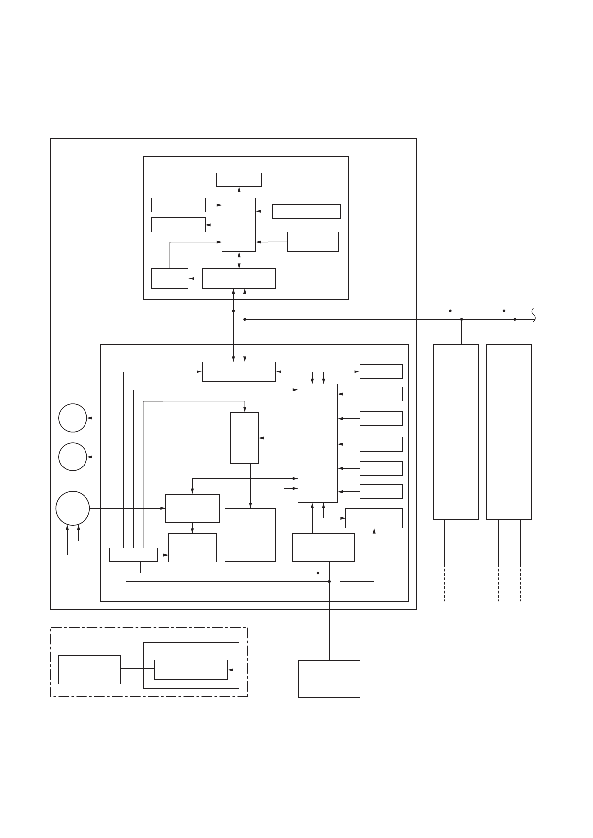
5-1. Indoor Controller Block Diagram
5-1-1. In Case of Connection of Wired (Simple) Remote Controller
Wired (Simple) heder remote controller (Max. 2 units) Central remote controller
Indoor unit
#1 (Heder)
*
None for
Duct type
Louver
motor
Drain
pump
*
Option for
Ceiling type
Indoor
fan motor
DC280V
Display LCD Function setup
Display LED
Remote controller
communication circuit
Indoor control P.C. board (MCC-1402)
Power circuit
DC20V
DC5V
DC12V
TMP88CH47FG
(TMP88PH47FG)
Fan motor
control circuit
Remote controller
communication circuit
CPU
CPU
AB
Driver
External
output
Run
Alarm
Defrost
Thermo. ON
COOL
HEAT
FAN
Key switch
DC5V
Power circuit
CPU
H8/3039
AC
synchronous
signal input circuit
CN2
CN1
∗3
EEPROM
TA sensor
TC sensor
TCJ sensor
Float input
Serial send/
receive circuit
Display LCD LCD driver
CPU
DC5V
HA
Powe r
circuit
Secondary
battery
#2
(Follower)
A B
Same as left
∗2
Function setup
Key switch
#3
(Follower)
A B
Same as left
321
1
∗2
32
∗ “1:1 model” connection interface
Central remote
controller(Option)
U3
U4
communication circuit
(Option)
P.C. board
(MCC-1440)
TCC-LINK
– 24 –
321
321
Outdoor unit
Outdoor unit
Up to 8 units are connectable. ∗1
∗1 However, if “1:1 model connection interface” is
connected when 2 wired (simple) remote controllers
are connected, Max. 7 units are connectable.
∗2 Connect “1:1 model connection interface” to only
1 unit and connect 1 “1:1 model connection
interface” to the header unit.
∗3 It is unavailable to connect the Central remote
controller to the simple wired remote controller.
Outdoor unit
Page 25
5-1-2. In Case of Connection of Wireless Remote Controller
Indoor unit
#1 (Heder)
Wireless remote controller
Receiver P.C. board (MCC-1504)
Display LED
*
None for
Duct type
Louver
motor
Drain
pump
*
Option for
Ceiling type
Indoor
fan motor
DC280V
Receive circuit
Buzzer
DC5V
Powe r
circuit
Indoor control P.C. board (MCC-1402)
DC20V
DC5V
DC12V
TMP88CH47FG
(TVP88PH47FG)
Fan motor
Power circuit
control circuit
Remote controller
communication circuit
Remote controller
communication circuit
CPU
CPU
AB
Driver
External
output
Run
Alarm
Defrost
Thermo. ON
COOL
HEAT
FAN
Function setup SW
Temporary
operation SW
CPU
H8/3039
AC
synchronous
signal input circuit
EEPROM
TA sensor
TC sensor
TCJ sensor
Float input
HA
Serial send/
receive circuit
#2
(Follower)
A B
Same as left
∗2
#3
(Follower)
A B
Same as left
321
1
∗2
32
∗ “1:1 model” connection interface
(MCC-1440)
communication circuit
Central remote
controller (Option)
U3
U4
(Option)
P.C. board
TCC-LINK
– 25 –
321
321
Outdoor unit
Outdoor unit
Up to 8 units are connectable. ∗1
∗1 However, if “1:1 model connection interface” is
connected when 2 wireless remote controllers are
connected, Max. 7 units are connectable.
∗2 Connect “1:1 model connection interface” to only
1 unit and connect 1 “1:1 model connection
interface” to the header unit.
Outdoor unit
Page 26
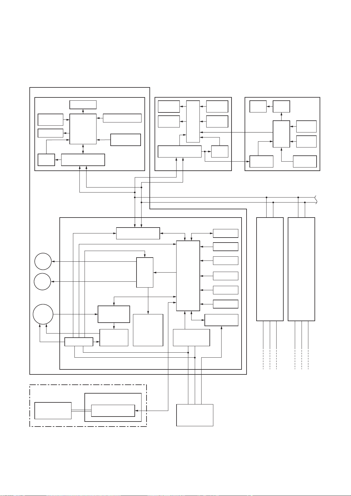
5-1-3. Connection of Both Wired (Simple) Remote Controller and Wireless Remote Controller
Indoor unit
#1 (Heder)
Receive
circuit
Buzzer
DC5V
Powe r
circuit
Display LED
CPU
Remote controller
communication circuit
Receiver P.C. board
(MCC-1504)
Function setup SW
Temporary
operation SW
Wired (Simple) heder remote controller
communication circuit
(Max. 2 units)
Display
LCD
Display
LED
Remote controller
ABAB
CPU
Function
setup
Key
switch
DC5V
Powe r
circuit
CN2
CN1
∗3
Central remote controllerWireless remote controller
Display
LCD
Powe r
circuit
DC5V
LCD
driver
CPU
Function
setup
Key
switch
Secondary
battery
*
None for
Duct type
Louver
motor
Drain
pump
*
Option for
Ceiling type
Indoor
fan motor
DC280V
Indoor control P.C. board (MCC-1402)
Power circuit
DC20V
DC5V
DC12V
TVP88CH47FG
(TMP88PH47FG)
control circuit
Remote controller
communication circuit
CPU
Fan motor
AB
Driver
External
output
Run
Alarm
Defrost
Thermo. ON
COOL
HEAT
FAN
CPU
H8/3039
AC
synchronous
signal input circuit
321
EEPROM
TA sensor
TC sensor
TCJ sensor
Float input
HA
Serial send/
receive circuit
#2
(Follower)
A B
Same as left
∗2
Outdoor unit
#3
(Follower)
A B
Same as left
321
1
Outdoor unit
∗2
32
∗ “1:1 model” connection interface
(MCC-1440)
Central remote
controller (Option)
U3
U4
communication circuit
(Option)
P.C. board
TCC-LINK
– 26 –
321
Outdoor unit
Up to 8 units are connectable. ∗1
∗1 However, if “1:1 model connection interface” is
connected, Max. 7 units are connectable.
∗2 Connect “1:1 model connection interface” to only
1 unit and connect 1 “1:1 model connection
interface” to the header unit.
∗3 It is unavailable to connect the Central remote
controller to the simple wired remote controller.
Page 27
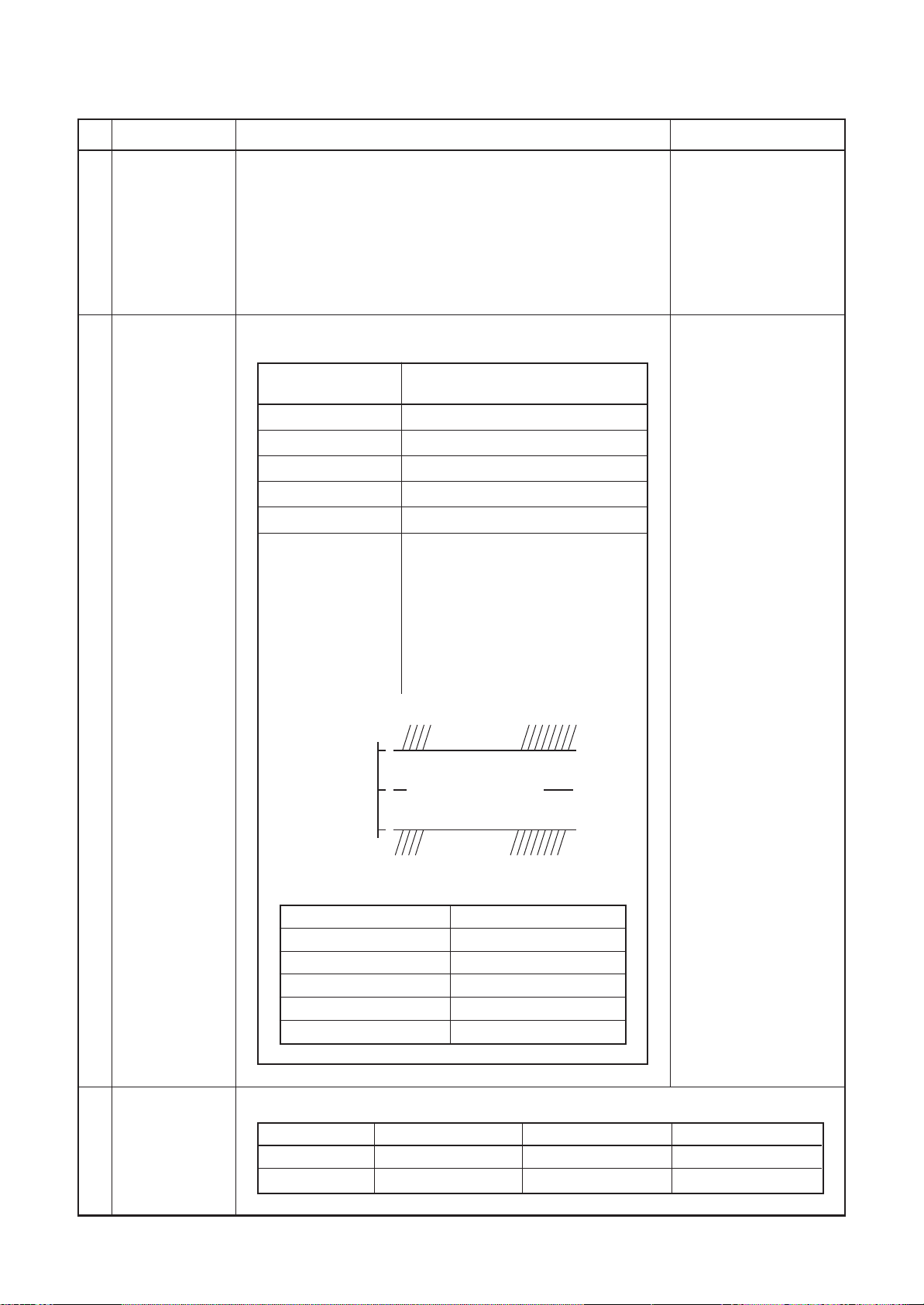
5-2. Control Specifications
No.
1
When power
supply is reset
2
Operation
mode selection
Item
Outline of specifications
1) Distinction of outdoor unit
When the power supply is reset, the outdoors are distin-
guished and the control is selected according to the
distinguished result.
2) Setting of indoor fan speed and existence of air direction
adjustment
Based on EEPROM data, select setting of the indoor fan
speed and the existence of air direction adjustment.
1) Based on the operation mode selecting command from the
remote controller, the operation mode is selected.
Remote controller
command
STOP
FAN
COOL
DRY
HEAT
AUTO
• COOL/HEAT operation mode is
automatically selected by Ta, Ts
and To for operation.
• The operation is performed as
shown in the following figure
according to Ta value at the first
time only. (In the range of Ts +
Control outline
Air conditioner stops.
Fan operation
Cooling operation
Dry operation
Heating operation
α –1 < Ta < Ts + α + 1, Cooling
thermo. OFF (Fan)/Setup air
volume operation continues.)
Remarks
Fan speed (rpm)/
Air direction adjustment
Ta: Room temp.
Ts: Setup temp.
To: Outside temp.
3
Room temp.
control
Cooling
1.0
Ta˚C Ts +
•
α is corrected according to the outside temperature.
α
–1.0
Outside temp.
No To
To ≥ 24°C
24°C > To ≥ 18°C
To < 18°C
To error
operation
Cooling thermo. OFF (Fan)
• Setup air volume
Heating
operation
Correction value (
0K
–1K
0K
+1K
0K
αα
α)
αα
1) Adjustment range: Remote controller setup temperature ( °C )
Wired type
Wireless type
COOL/DRY
18°C to 29°C
18°C to 30°C
HEAT
18°C to 29°C
16°C to 30°C
K = deg
AUTO
18°C to 29°C
17°C to 27°C
– 27 –
Page 28
No.
3
Room temp.
control
(Continued)
4
Automatic
capacity control
(GA control)
Item
Outline of specifications
2) Using the CODE No. 06, the setup temperature in heating
operation can be corrected.
SET DATA
Setup temp.
correction
0246
+0°C +2°C +4°C +6°C
Setting at shipment
SET DATA 2
1) Based on the difference between Ta and Ts, the operation
frequency is instructed to the outdoor unit.
2) Cooling operation
Every 90 seconds, the room temperature difference
between temperature detected by Ta and Ts and the
varied room temperature value are calculated to obtain
the correction value of the frequency command and then
the present frequency command is corrected.
Ta (n) – Ts (n) : Room temp. difference
n : Counts of detection
Ta (n-1) – Ts (n) : Varied room temp. value
n – 1 :
Counts of detection of 90 seconds before
3) Heating operation
Every 1 minute (60 sec.), the room temperature differ-
ence between temperature detected by Ta and Ts and the
varied room temperature value are calculated to obtain
the correction value of the frequency command and then
the present frequency command is corrected.
Ts (n) – Ta (n) : Room temp. difference
n : Counts of detection
Ta (n) – Ta (n – 1) : Varied room temp. value
n – 1 : Counts of detection of 1 minute before
4) Dry operation
The frequency correction control is same as those of the
cooling operation.
However the maximum frequency is limited to approxi-
mately “S6”.
Note) When LOW is set up, the maximum frequency is
limited to approximately “SB”.
Remarks
Shift of suction
temperature in heating
operation
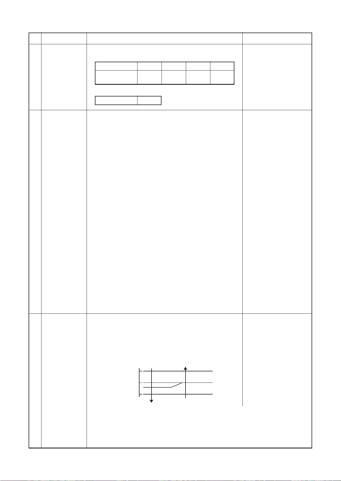
5
Automatic
cooling/heating
control
1) The judgment of selecting COOL/HEAT is carried out as
shown below. When +1.5°C exceeds against Tsh 10
minutes and after thermo. OFF, heating operation
(Thermo. OFF) exchanges to cooling operation.
Description in the parentheses shows an example of
cooling ON/OFF.
Tsc: Setup temp. in
cooling operation
Tsh: Setup temp. in
heating operation
+ temp. correction of
room temp. control
+1.5
–1.5
Cooling
(Cooling ON)
(Cooling OFF)
Heating
Ta ˚C
Tsc or Tsh
When –1.5°C lowers against Tsc 10 minutes and after thermo. OFF, cooling operation
(Thermo. OFF) exchanges to heating operation.
2) For the automatic capacity control after judgment of cooling/heating, see Item 4.
3) For temperature correction of room temp. control in automatic heating, see Item 3.
– 28 –
Page 29
No.
6
Fan speed control
Item
Outline of specifications
1) Operation with (HH), (H), (L) or [AUTO] mode is carried
out by the command from the remote controller.
2) When the fan speed mode [AUTO] is selected, the fan
speed varies by the difference between Ta and Ts.
<COOL>
Remarks
HH > H+ > H > L+ >
L > UL
Ta ˚C
+3.0
+2.5
+2.0
+1.5
+1.0
+0.5
Tsc
–0.5
HH
(HH)
H+ (HH)
H (HH)
L+ (H+)
L (H)
L (H)
L (L+)
A
B
C
D
E
F
G
• Controlling operation in case when thermostat of remote
controller works is same as a case when thermostat of the
body works.
• If the fan speed has been changed once, it is not changed
for 3 minutes. However when the air volume is exchanged,
the fan speed changes.
• When cooling operation has started, select a downward
slope for the fan speed, that is, the high position.
• If the temperature is just on the difference boundary, the
fan speed does not change.
• Mode in the parentheses indicates one in automatic
cooling operation.
<HEAT>
Ta ˚C
(–0.5) –1.0
(0) Tsh
(+0.5) +1.0
(+1.0) +2.0
(+1.5) +3.0
(+2.0) +4.0
L (L+)
L+ (H)
H (H+)
H+
(HH)
HH
(HH)
E
D
C
B
A
Value in the parentheses indicates one when thermostat of
the remote controller works.
Value without parentheses indicates one when thermostat of
the body works.
• If the fan speed has been changed once, it is not changed
for 1 minute. However when the fan speed exchanged, the
fan speed changes.
• When heating operation has started, select an upward
slope for the fan speed, that is, the high position.
• If the temperature is just on the difference boundary, the
fan speed does not change.
• Mode in the parentheses indicates one in automatic
heating operation.
• In Tc ≥ 60°C, the fan speed increases by 1 step.
Tc: Indoor heat
exchanger sensor
temperature
– 29 –
Page 30
No.
6
Fan speed control
(Continued)
Item
Outline of specifications
(Ceiling type)
CODE No.
[5d]
SW501 (1)/(2)
Tap
F1
F2
F3
F4
F5
F6
F7
F8
F9
FA
FB
FC
FD
Standard Type 1 Type 3 Type 6
0000 0001 0002 0003
OFF/OFF ON/OFF OFF/ON ON/ON
HEAT COOL HEAT COOL HEAT COOL HEAT COOL
HH HH HH HH
HH HH
H+ H+, H H+, H
H+
HH H
HH H L+ L+
H+ H+ L L
HL+
HL+L
L+ L
L+ L
L
UL UL UL UL
H+, H H+, H
L+, L L+, L
3) In heating operation, the mode changes to [UL] if thermostat
is turned off.
4) If Ta ≥ 25°C when heating operation has started and when
defrost operation has been cleared, the air conditioner
operates with (H) mode or higher mode for
1 minute after Tc entered in E zone of cool air discharge
preventive control (No. 7).
5) In automatic cooling/heating operation, the revolution
frequency of (HH) is set larger than that in the standard
cooling/heating operation.
Ta ˚C
F5 → F4
Remarks
Selection of high
ceiling type
CODE No.: 5d
However only when
the high ceiling
selection is set to
[Standard]
7
Cool air discharge
preventive control
47
However the revolution frequency
is restricted in the automatic
heating operation as shown in
42
F5
the following figure.
6) Self-clean operation
When performing self-clean operation after stopping the
cooling operation, the mode becomes 210 rpm.
1) In heating operation, the indoor fan is controlled based on
the detected temperature of Tc sensor or Tcj sensor. As
shown below, the upper limit of the revolution frequency is
restricted.
However B zone is assumed as C zone for
6 minutes and after when the compressor activated.
In defrost operation, the control value of Tc is shifted by 6°C.
Tc, Tcj
˚C
HH
32
H
30
28
26
20
16
L
UL
OFF
E zone
D zone
C zone
B zone
A zone
[Self-clean
] is
displayed.
In D and E zones,
the priority is given
to air volume
selection setup of
remote controller.
In A zone while
thermo is ON,
[PRE-HEAT
(Heating ready)] is
displayed.
– 30 –
Page 31

No.
8
Freeze preventive control
(Low temperature release)
Item
Outline of specifications
1) The cooling operation (including Dry operation) is
performed as follows based on the detected
temperature of Tc sensor or Tcj sensor.
When [J] zone is detected for 6 minutes
(Following figure), the commanded frequency is
decreased from the real operation frequency.
After then the commanded frequency changes
every 30 seconds while operation is performed in
[J] zone.
In [K] zone, time counting is interrupted and the
operation is held.
When [ I ] zone is detected, the timer is cleared
and the operation returns to the normal operation.
If the commanded frequency becomes S0
because the operation continues in [J] zone, the
return temperature A is raised from 5°C to 12°C
until [ I ] zone is detected and the indoor fan
operates with [L] mode.
˚C
5
I
A
K
Remarks
Tcj:
Indoor heat exchanger
sensor temperature
2
J
In heating operation, the freeze-preventive control
works if 4-way valve is not exchanged and the
following conditions are satisfied.
(However the temperature for J zone dashing control
is changed from 2°C to –5°C.)
<Conditions>
• When
activation.
Q
R
or R is established 5 minutes after
Q
Tcn ≤ Tc (n – 1) – 5
Tcn < Tc (n – 1) – 1 and Tcn ≤ Ta < 5°C
Tcn:
Tc temperature when 5
minutes elapsed after
activation
Tc (n – 1):
Tc temperature at start
time
– 31 –
Page 32

No.
9
High-temp.
release control
Item
Outline of specifications
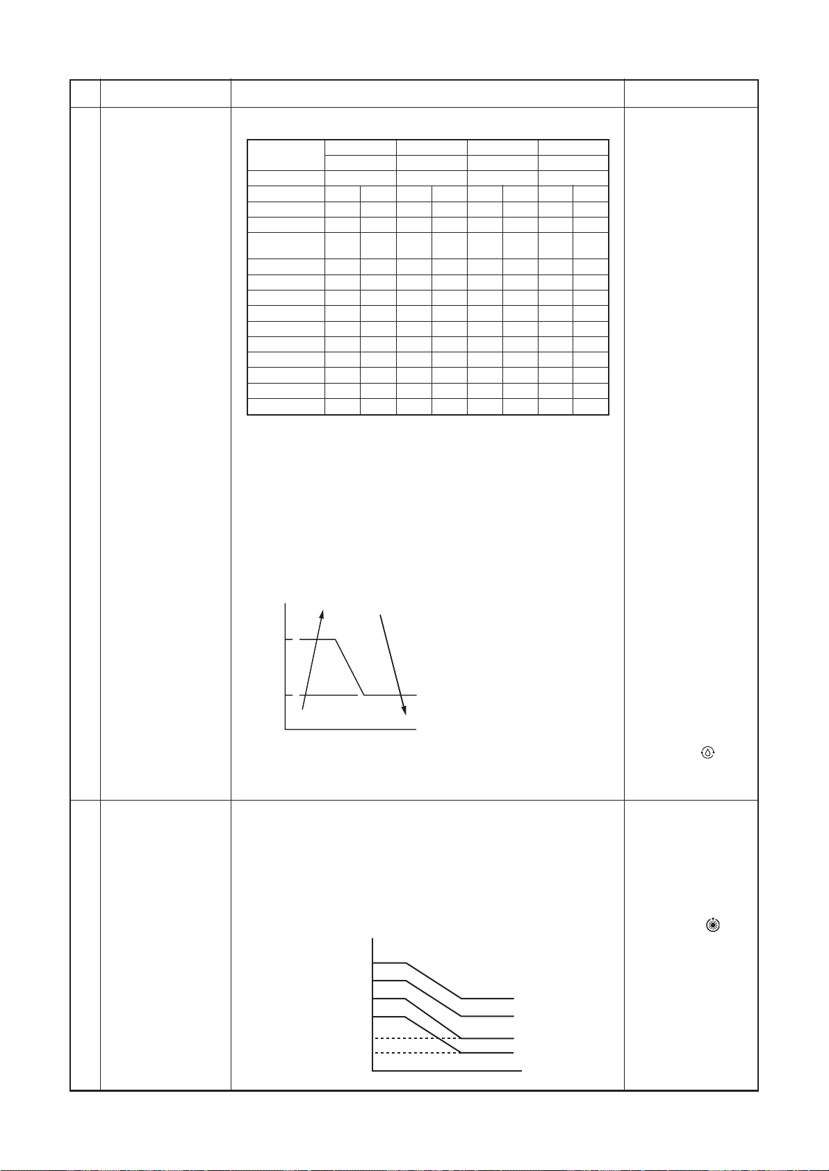
1) The heating operation is performed as follows based on the
detected temperature of Tc sensor or Tcj sensor.
• When [M] zone is detected, the commanded frequency is
decreased from the real operation frequency. After then
the commanded frequency changes every 30 seconds
while operation is performed in [M] zone.
• In [N] zone, the commanded frequency is held.
• When [L] zone is detected, the commanded frequency is
returned to the original value by approx. 6Hz every
60 seconds.
Remarks
However this control is
ignored in case of the
follower unit of the twin.
10
Drain pump
control
(The ceiling
type is optional)
Setup at shipment
Control temp. °C
AB
56 (54) 52 (52)
Tc, Tcj
˚C
A
M
N
B
L
NOTE:
When the operation has started or when Tc or Tcj < 30°C at start
of the operation or after operation start, temperature is controlled between values in parentheses of A and B.
1) In cooling operation (including Dry operation), the drain
pump is usually operated.
2) If the float switch works while drain pump drives, the
compressor stops, the drain pump continues the operation,
and a check code is output.
3) If the float switch works while drain pump stops, the
compressor stops and the drain pump operates. If the float
switch keeps operating for approx. 4 minutes, a check code
is output.
Same status as that
when “thermostat-OFF”
(status that the air
conditioner enters in the
room temp. monitor
mode when the
temperature reached the
setup temperature on
the remote controller)
Check code [P10]
11
After-heat
elimination
When heating operation stops, in some cases, the indoor fan
operates with (L) for approx. 30 seconds.
– 32 –
Page 33

No.
12
Louver control:
Compact 4-way
type only
Item
Outline of specifications
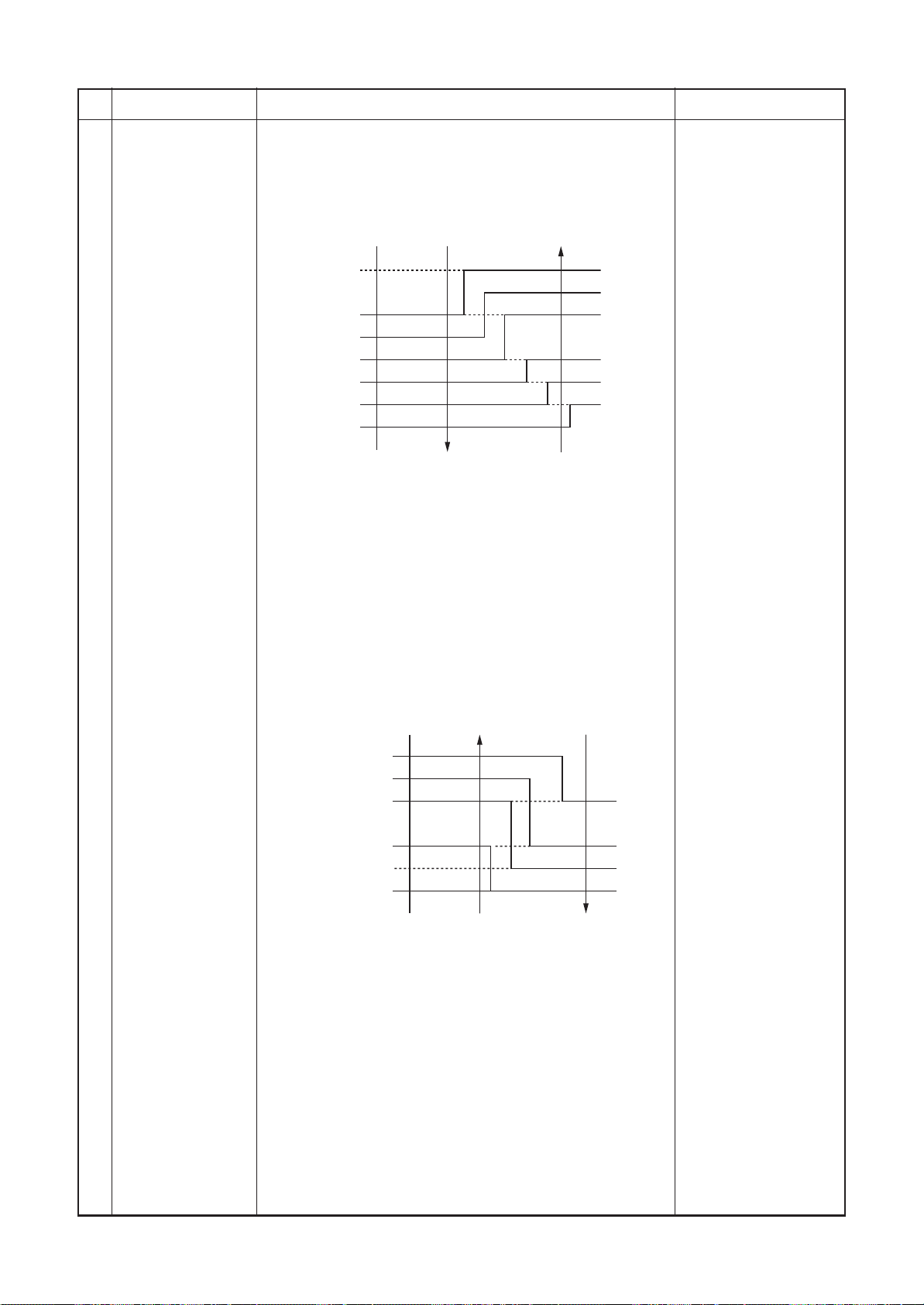
1) Louver position setup
• When the louver position is changed, the position moves
necessarily to downward discharge position once to return to
the set position.
The louver position can be set up in the following operation range.
•
In cooling/dry operation In heating/fan operation
• In group twin/triple operation, the louver positions can be set
up collectively or individually.
2) Swing setup
• [SWING] is displayed and the following display is repeated.
In all operations
(Repeats)
Remarks
The swinging
louver moves
usually up to the
ceiling side from
the louver position
of the set time.
• In group twin operation, the louver positions can be set up
collectively or individually.
3) When the unit stopped or the warning was output, the louver is
automatically set to full closed position.
4) When PRE-HEAT
(Heating operation started or defrost operation is performed),
heating thermo is off or self-cleaning is performed, the louver is
automatically set to horizontal discharge position.
∗ The louver which air direction is individually set or the locked
louver closes fully when the unit stops and the louver is
automatically set to horizontal discharge position when
PRE-HEAT
off or self-cleaning is performed.
(Heating ready) is displayed
(Heating ready) is displayed, heating thermo is
– 33 –
Page 34

No.
13
(Continued)
For ceiling type only
Item
Outline of specifications
1) Louver position setup
• When the louver position is changed, the position
moves necessarily to downward discharge position
once to return to the set position.
• The louver position can be set up in the following
operation range.
In cooling/dry operation In heating/fan operation
• In group operation, the louver positions can be set up
collectively or individually.
2) Swing setup
• The swinging position can be moved in the following
operation range.
All modes
Remarks
• In group operation, the swinging positions can be set
up collectively or individually.
3) When the unit stops or when a warning is output, the
louver automatically moves downward.
4) While the heating operation is ready or self cleaning,
the louver automatically moves upward.
Alarm :
A check code is
displayed on the
remote controller, and
the indoor unit stops.
(Excluding [F08] and
[L31])
– 34 –
Page 35

No.
13
Frequency
fixed operation
(Test run)
Item
Outline of specifications
<In case of wired remote controller>
1) When pushing [CHK] button for 4 seconds or more, [TEST] is
displayed on the display screen and the mode enters in Test
run mode.
2) Push [ON/OFF] button.
3) Using [MODE] button, set the mode to [COOL] or [HEAT].
• Do not use other mode than [COOL]/[HEAT] mode.
• During test run operation, the temperature cannot be ad-
justed.
• An error is detected as usual.
• A frequency fixed operation is performed.
4) After the test run, push [ON/OFF] button to stop the operation.
(Display in the display part is same as the procedure in Item 1.)
5) Push [CHK] button to clear the test run mode.
([TEST] display in the display part disappears and the status
returns to the normal stop status.)
<In case of wireless remote controller>
(Compact 4-way, Concealed Duct type)
1) Turn off power of the set.
Remove the nameplate of the receiver unit and then turn the
Dip switch to [Test operation / ON].
2) The test operation starts by [START/STOP] button.
• [START], [TIMER] and [READY] LEDs flash during test
operation
• Under condition of [Test operation / ON], the temperature
adjustment is invalid even if using the wireless remote
controller. Do not use it at other cases than a test operation
because it applies excessive force.
3) Carry out a test operation under anyone mode of HEAT,
COOL or FAN operation mode.
• The outdoor unit does not operate for approx. 3 minutes
after the power supply was turned on and after operation
stop.
4) After the test operation, stop the unit by the wireless remote
controller and then return Dip switch of the receiver unit to
the original position.
(In order to prevent sequential test operation, this receiving
unit is attached with 60-minutes timer release function.)
Remarks
Command frequency is
approximately [S7]
Small screw
M4 × 25 screw
(2 pieces)
Notch
Nameplate
Receiver unit
Spacer
– 35 –
Page 36

No.
6
13
Frequency fixed
operation
(Test run)
(Continued)
Item
(Ceiling type)
Procedure
4
2
3
4
5
6
7
Outline of specifications
Description
Turn on power of the air conditioner.
The operation is not accepted for 5 minutes when power has been turned on at first time after
installation, and 1 minute when power has been turned on at the next time and after. After the
specified time has passed, perform a test operation.
Push [Start/Stop] button and change the operation mode to [COOL] or [HEAT] with [Mode] button.
Then change the fan speed to [High] using [Fan] button.
Test cooling operation Test heating operation
Set temperature to [18°C] using Set temperature to [30°C] using
[Temperature set] button. [Temperature set] button.
After checking the receiving sound After checking the receiving sound
“Pi”, immediately push [Temperature set] “Pi”, immediately push [Temperature set]
button to set to [19°C] button to set to [29°C].
After checking the receiving sound “Pi”, After checking the receiving sound “Pi”,
immediately push [Temperature set] button immediately push [Temperature set] button
to set to [18°C]. to set to [30°C].
Then repeat the procedure 4 → 5 → 4 → 5 .
After approx. 10 seconds, all the display lamps on the sensor part of wireless remote controller,
[Operation] (Green), [Timer] (Green), and [Ready] (Yellow) flash and the air conditioner starts operation.
If the lamps do not flash, repeat the procedure 2 and after.
After the test operation, push [Start/Stop] button to stop the operation.
Remarks
14 Filter sign display
(Except wireless
type)
∗ It is provided
on the separately sold type
TCB-AX21E2.
<Outline of test operation from the wireless remote controller>
Test cooling operation:
Start → 18°C → 19°C → 18°C → 19°C → 18°C → 19°C → 18°C → (Test operation) → Stop
Test heating operation:
Start → 30°C → 29°C → 30°C → 29°C → 30°C → 29°C → 30°C → (Test operation) → Stop
Be sure to set the
air speed to [High]
2
3, 4, 5,
2, 7
1) The operation time of the indoor fan is calculated, the filter
reset signal is sent to the remote controller when the
specified time (2500H) has passed, and it is displayed on
LCD.
2) When the filter reset signal has been received from the
remote controller, time of the calculation timer is cleared.
In this case, the measurement time is reset if the specified
time has passed, and display on LCD disappears.
[FILTER ] goes on.
– 36 –
Page 37

No.
15
Central control
mode selection
Item
Outline of specifications
1) Setting at the central controller side enables to select
the contents which can be operated on the wired
remote controller.
2) Setup contents
• In case of TCC-LINK Central remote controller
(TCB-SC642TLE2)
[Individual]:
Operated by wired remote controller
([After-push precedence])
[Central 1]:
START / STOP operation by wired remote controller
is unavailable.
[Central 2]:
START / STOP, MODE change and TEMP. setting by
wired remote controller are unavailable.
[Central 3]:
MODE change and TEMP. setting by wired remote
controller are unavailable.
[Central 4]:
MODE change by wired remote controller is
unavailable.
• In case of the wireless remote controller, the con-
tents to be operated are same though the display
lamp does not change.
If an item prohibited by the central control mode is
operated from the remote controller, it is notified with
receiving sound Pi, Pi, Pi, Pi, Pi (5 times)
Remarks
Display at wired remote
controller side (No display)
[
] goes on.
] goes on.
[
[
] goes on.
[
] goes on.
16
Energy-saving
control
17
Max. frequency
cut control
1) Selecting [AUTO] mode enables an energy-saving to
be operated.
2) The setup temperature is shifted (corrected) in the
range not to lose the comfort ability according to input
values of various sensors.
3) Data (Input value room temp. Ta, Outside temp. To, Air
volume, Indoor heat exchanger sensor temp. Tc) for
20 minutes are taken the average to calculate correction value of the setup temperature.
4) The setup temperature is shifted every 20 minutes,
and the shifted range is as follows.
In cooling time: +1.5 to – 1.0K
In heating time: –1.5 to +1.0K.
1) This control is operated by selecting [AUTO] operation mode.
2) COOL operation mode:
It is controlled according to the following
figure if To < 28°C.
Ta ˚C
Normal control
+4
+3
3) HEAT operation mode:
It is controlled according to the following
figure if To > 15°C.
Max. frequency is
Ta ˚C
Tsh
–3
restricted to approximately
the rated heating frequency
Tsc
Max. frequency is
restricted to approximately
the rated cooling frequency
– 37 –
–4
Normal control
Page 38

No.
SAVE
SAVE
18
DC motor
19
Self-clean
operation
(Dry operation)
Item
Outline of specifications
Remarks
1) When the fan operation has started, positioning of
the stator and the rotor are performed.
(Moves slightly with tap sound)
2) The motor operates according to the command from
the indoor controller.
Notes)
• When the fan rotates while the air conditioner stops
due to entering of outside air, etc, the air conditioner
may operate while the fan motor stops.
• When a fan lock is found, the air conditioner stops, and
Check code [P12]
an error is displayed.
1) When cooling operation mode (AUTO COOL, COOL, DRY) stopped, the following
three self-clean operations are performed.
Compressor
ON period
0 to 10 min.
10 to 60 min.
60 min. to
Self-clean
operation period
None
1 hour
2 hours
FA N
Fan (UL)
Drain pump
STOP
Louver
Horizontal discharge
position
∗Concealed duct is none.
20
Save operation
2) During operation of self-clean, lights on the wired
remote controller screen. However the operation
lamp (Green LED) goes off.
3) To stop the self-clean operation, push twice the
[ON/OFF] button on the remote controller
continuously. (Stop the operation as compressor ON
time in the table above: 10 minutes or below.)
4) When the follower unit executes self-clean operation
in the group connection, the segment of
is
displayed on the wired remote controller screen via
master unit.
∗ If self-clean operation is not used, set invalidity
(does not use) of the self-clean operation by
changing [0001 (At shipment) of CODE No. (DN)
[D3] to [0000].
∗ To erase the
display during operation of
self-clean, change CODE No. [D4] from [0000:
Display (At shipment)] to [0001: Non-display].
1) Turn on
2) During operation of save operation,
button on the remote controller.
lights on the
wired remote controller.
3) During save operation, the current release control is
performed with the restriction ratio set in EEPROM
on the outdoor unit.
4) The restriction ratio can be set by keeping
button pushed for 4 seconds or more on the remote
controller.
5) When validating the save operation, the next operation starts with save operation valid because contents
are held even when operation stops, operation mode
changes or power supply is reset.
6) The restriction ratio can be set by changing the setup
data of CODE No. (DN) [C2] in the range of 50 to
100% (every 1%, Setting at shipment: 75%).
And it is not also on the
wireless remote controller.
It is recognized as [STOP]
from the remote monitor
side.
Carry out setting
operation during stop of
the unit; otherwise the
unit stops operation.
For the setup operation,
refer to
“How to set contents of
save operation” in Sction
“8. SETUP AT LOCAL
SITE AND OTHERS”.
– 38 –
Page 39

No.
21
8°C heating/Frost
protective operation
Item
Outline of specifications
1) This functional is intended for the cold latitudes and
performs objective heating operation
(8°C heating operation).
2) This function is valid only for combination with the
outdoor units.
3) Using the indoor CODE No. [D1] (1 bit), Valid/Invalid of
this function is set up at the customer’s side.
∗ The setup by CODE No. is Invalid [0]/Valid [1] and
Invalid [0] has been set at the shipment.
4) This operation is the heating operation which sets 8°C
as the setup temperature of the target.
5) This function starts operation by pushing temperature
button
pushing
temperature reached the minimum set temperature.
6) To stop/release this operation, select and execute one
from the following operations.
Push button:
Q
Heating operation 18°C setting) continues.
Push [START/STOP] button:
R
Air conditioner stops.
(Heating 18°C operation at the next start)
Push
S
Other operation mode is selected and the operation
continues.
7) As the setup temperature is 8°C and the human heating is
not targeted, the cold air discharge preventive control
(Item 7) is made invalid to suppress the intermittent
operation.
8) The settings of the air direction and air volume are
changeable during this operation.
9) The indoor fan stops to protect the compressor for
2 minutes after start of heating operation
(Thermo-ON) by this function.
during heating operation; besides by
button for 4 seconds or more after
MODE
:
Remarks
In a group connection,
if there is even one
combination with other
unit, “This function is not
provided.” is displayed.
The setup temperature
jumps from [18] to [8].
– 39 –
Page 40

5-3. Indoor Print Circuit Board
5-3-1. Compact 4-way Cassette Type / Concealed Duct Type / Ceiling Type
<MCC-1402>
Optional
Indoor/Outdoor
inter-unit cable
power supply
Remote controller
power supply LED
Drain pump output
Filter/Option error input EEPROM Connection interface
Microcomputer operation LED
TC sensor
Used for
TCJ sensor
EXCT
Fan output
servicing
DISP
CHK
TA sensor Remote controller inter-unit wire
HA (T10)
Optional output
DC fan output
– 40 –
Louver
DC fan return
Float SW
(Used only for Compact 4-way Cassette Type, Ceiling Type)
Page 41

Indoor P.C. Board Optional Connector Specifications (MCC-1402)
Function
Option output
Outside error input
CHK
Operation check
DISP display mode
Connector
No.
CN60
CN80
CN71
CN72
Pin
No.
1
DC12V (COM)
2
Defrost output
3
Thermo. ON output
4
Cooling output
5
Heating output
6
Fan output
1
DC12V (COM)
2
DC12V (COM)
3
Outside error input
1
Check mode input
2
0V
1
Display mode input
Specifications
Remarks
ON during defrost operation of outdoor unit
ON during Real thermo-ON (Comp ON)
ON when operation mode is in cooling system
(COOL, DRY, COOL in AUTO cooling/heating)
ON when operation mode is in heating system
(HEAT, HEAT in AUTO cooling/heating)
ON during indoor fan ON
(Air purifier is used/Interlock cable)
(When continued for 1 minute)
Check code “L30” is output and forced operation stops.
Used for operation check of indoor unit.
(Communication with outdoor unit or remote controller
is not performed, but the specified operation such as
indoor fan “H” or drain pump ON is output.)
EXCT demand
CN73
2
0V
1
Demand input
2
0V
Display mode enables indoor unit and remote controller
to communicate. (When power is turned on)
Forced thermo-OFF operation in indoor unit
– 41 –
Page 42

6. TROUBLESHOOTING
6-1. Summary of Troubleshooting
<Wired remote controller type>
1. Before troubleshooting
1) Required tools/instruments
+
•
and – screwdrivers, spanners, radio cutting pliers, nippers, push pins for reset switch
• Tester, thermometer, pressure gauge, etc.
2) Confirmation points before check
a) The following operations are normal.
1. Compressor does not operate.
• Is not 3-minutes delay (3 minutes after compressor OFF)?
• Is not the outdoor unit in standby status though the remote controller reached the setup
temperature?
• Does not timer operate during fan operation?
• Is not an overflow error detected on the indoor unit?
• Is not outside high-temperature operation controlled in heating operation?
2. Indoor fan does not rotate.
• Does not cool air discharge preventive control work in heating operation?
3. Outdoor fan does not rotate or air volume changes.
• Does not high-temperature release operation control work in heating operation?
• Does not outside low-temperature operation control work in cooling operation?
• Is not defrost operation performed?
4. ON/OFF operation cannot be performed from remote controller.
• Is not automatic address being set up?
(When the power is turned on at the first time or when indoor unit address setting is changed,
the operation cannot be performed for maximum approx. 5 minutes after power-ON.)
• Is not being carried out a test run by operation of the outdoor P.C. board?
b) Did you return the cabling to the initial positions?
c) Are connecting cables of indoor unit and remote controller correct?
2. Troubleshooting procedure
When a trouble occurred, check the parts along with the following procedure.
Trouble Confirmation of check code display Check defective parts.
→ →
NOTE :
For cause of a trouble, power conditions or malfunction/erroneous diagnosis of microcomputer due to outer
noise is considered except the items to be checked. If there is any noise source, change the cables of the
remote controller to shield cables.
– 42 –
Page 43

<Wireless remote controller type>
1. Before troubleshooting
1) Required tools/instruments
•+ and – screwdrivers, spanners, radio cutting pliers, nippers, etc.
• Tester, thermometer, pressure gauge, etc.
2) Confirmation points before check
a) The following operations are normal.
1. Compressor does not operate.
• Is not 3-minutes delay (3 minutes after compressor OFF)?
• Is not the outdoor unit in standby status though the remote controller reached the setup
temperature?
• Does not timer operate during fan operation?
• Is not an overflow error detected on the indoor unit?
• Is not outside high-temperature operation controlled in heating operation?
2. Indoor fan does not rotate.
• Does not cool air discharge preventive control work in heating operation?
3. Outdoor fan does not rotate or air volume changes.
• Does not high-temperature release operation control work in heating operation?
• Does not outside low-temperature operation control work in cooling operation?
• Is not defrost operation performed?
4. ON/OFF operation cannot be performed from remote controller.
• Is not forced operation performed?
• Is not the control operation performed from outside/remote side?
• Is not automatic address being set up?
• Is not being carried out a test run by operation of the outdoor controller?
b) Did you return the cabling to the initial positions?
c) Are connecting cables between indoor unit and receiving unit correct?
2. Troubleshooting procedure
(When the power is turned on at the first time or when indoor unit address setting is changed, the operation
cannot be performed for maximum approx. 5 minutes after power-ON.)
When a trouble occurred, check the parts along with the following procedure.
Trouble
Confirmation of lamp display
→→
(When wireless remote controller is connected)
Check defective
position and parts.
– 43 –
Page 44

Outline of judgment
The primary judgment to check whether a trouble occurred in the indoor unit or outdoor unit is carried out with
the following method.
Method to judge the erroneous position by display panel of the indoor unit
(lamp display of the wireless receiving part)
The indoor unit monitors the operating status of the air conditioner, and the blocked contents of self-diagnosis
are displayed restricted to the following cases if a protective circuit works.
: Go off, : Go on, : Flash (0.5 sec.)
Lamp indication
Operation
No indication at all
Operation
Flash
Operation
Operation
Timer Ready
Timer Ready
Timer Ready
Flash
Timer Ready
Alternate flash
Check code
—
E01
E02
E03
E08
E09
E10
E18
E04
P10
P12
Cause of trouble occurrence
Power supply OFF or miswiring between lamp indication unit and indoor unit
Receiving error
Sending error
Communication stop
Duplicated indoor unit No.
Duplicated master units of remote controller
⎫
⎬
Receiving unit
⎭
⎫
⎪
Miswiring or wire connection error
⎬
between receiving unit and indoor unit
⎪
⎭
⎫
Setup error
⎬
⎭
Communication error between CPUs on indoor unit P.C. board
Wire connection error between indoor units, Indoor power OFF
(Communication stop between indoor header and follower)
Miswiring between indoor unit and outdoor unit or connection erorr
(Communication stop between indoor and outdoor units)
Overflow was detected.
Indoor DC fan error
⎫
⎪
⎬
Protective device of indoor unit worked.
⎪
⎭
Operation
Timer Ready
Alternate flash
P03
P04
P05
P07
P15
P19
P20
P22
P26
P29
P31
Outdoor unit discharge temp. error
Outdoor high pressure system error
Negative phase detection error
Heat sink overheat error Outdoor unit error
Gas leak detection error
⎫
Protective device of
⎬
outdoor unit worked.
⎭
⎫
⎪
⎬
⎪
⎭
∗1
4-way valve system error (Indoor or outdoor unit judged.)
Outdoor unit high pressure protection
Outdoor unit: Outdoor unit error
Outdoor unit: Inverter Idc operation ∗1
Outdoor unit: Position detection error
⎫
⎪
Protective device of
⎬
outdoor unit worked.
⎪
⎭
Stopped because of error of other indoor unit in a group
(Check codes of E03/L03/L07/L08)
∗1: These are representative examples and the check code differs according to the outdoor unit to be combined.
– 44 –
Page 45

Lamp indication
Operation
Alternate flash
Operation
Alternate flash
Operation
Timer Ready
Timer Ready
Timer Ready
Check code
F01
F02
F10
F04
F06
F07
F08
F12
F13
F15
Cause of trouble occurrence
Heat exchanger sensor (TCJ) error
Heat exchanger sensor (TC) error Indoor unit sensor error
Heat exchanger sensor (TA) error
Discharge temp. sensor (TD) error
Temp. sensor (TE) error
Temp. sensor (TL) error
Temp. sensor (TO) error Sensor error of outdoor unit ∗1
Temp. sensor (TS) error
Temp. sensor (TH) error
Temp. Sensor miswiring (TE, TS)
⎫
⎪
⎬
⎪
⎭
⎫
⎪
⎪
⎪
⎪
⎪
⎪
⎬
⎪
⎪
⎪
⎪
⎪
⎪
⎭
Simultaneous flash
Operation
Timer Ready
Simultaneous flash
Operation
Timer Ready
Flash
Operation
Timer Ready
Simultaneous flash
Operation
Timer Ready
Simultaneous flash
F29
F31
H01
H02
H03
H04
H06
L03
L07
L08
L09
L10
L20
L29
L30
L31
Indoor EEPROM error
Outdoor EEPROM error
Compressor break down
Compressor lock
Current detection circuit error
Case thermostat worked.
⎫
⎪
⎪
⎬
Outdoor compressor system error ∗1
⎪
⎪
⎭
Outdoor unit low pressure system error
Duplicated header indoor units
There is indoor unit of group connection → AUTO address
in individual indoor unit.
Unsetting of group address
Missed setting
(Unset indoor capacity)
Unset model type (Service board)
Duplicated indoor central addresses
Outdoor unit and other error Others
Outside interlock error
Negative phase error
⎫
⎪
⎪
⎬
⎪
∗ If group construction and
⎪
address are not normal
⎭
when power supply turned on,
automatically goes to address
setup mode.
⎫
⎪
⎪
⎪
⎪
⎬
⎪
⎪
⎪
⎪
⎭
∗1: These are representative examples and the check code differs according to the outdoor unit to be combined.
– 45 –
Page 46

Others (Other than Check Code)
Lamp indication
Operation Timer Ready
Simultaneous flash
Operation Timer Ready
Alternate flash
Check code
—
—
Cause of trouble occurrence
During test run
Disagreement cool/heat
(Automatic cool/heat setting to automatic cool/heat prohibited mode)
– 46 –
Page 47

continuation
¡×¡×¡×¡×¡×¡×¡×¡
reset
Automatic Operation
Air conditioner operation
×
××
××
××
×
××
××
¡
×
××
××
××
××
¡×¡
continuation
——
——
reset
Automatic Operation
Air conditioner operation
×
continuation
——
——
——
reset
Automatic Operation
Air conditioner operation
——
Explanation of error contents
No communication from remote controller and network adapter
(Also no communication from central control system)
There is error on serial communication between indoor and outdoor units
Representative defective position
Same address as yours was detected.
MCU communication error between main motor and micro computer
Regular communication between indoor master and follower units is impossible.
Open/short was detected on heat exchanger (TCJ).
Open/short was detected on heat exchanger (TC).
Open/short was detected on room temp. sensor (TA).
EEPROM error (Other error may be detected. If no error, automatic address is repeated.
There are multiple master units in a group.
²
²
When even one group connection indoor unit exists in individual indoor unit.
Indoor group address is unset.
Capacity of indoor unit is unset.
Duplicated setting of central control system address
Abnormal stop by outside error (CN80) input
An error of indoor AC fan was detected. (Fan motor thermal relay worked.)
Float switch worked.
²
²
Explanation of error contents
Indoor DC fan error (Over-current/Lock, etc.) was detected.
In heating operation, an error was detected by temp. down of indoor heat exchanger sensor.
Follower unit in group cannot operate by warning from [E03/L03/L07/L08] of master unit.
When this warning was detected before group construction/address check finish at power supply was turned on, the mode shifts automatically to AUTO address setup mode.
²
Representative defective position
Explanation of error contents
Signal cannot be received from indoor unit. Master remote controller was not set. (including 2 remote controllers)
Signal cannot be sent to indoor unit.
In 2-remote controller control, both were set as master.
(Indoor master unit stops warning and follower unit continues operation.)
Representative defective position
Signal sending operation of central control system is impossible. There are multiple same central devices. (AI-NET)
Signal receiving operation of central control system is impossible.
An error on device connected to general-purpose device control interface of exclusive to TCC-LINK/AI-NET
Group follower unit is defective. (For remote controller, above-mentioned [∗∗∗] details are displayed with unit No.)
Regular communication error between indoor and remote controller
Indoor/Outdoor serial error
Duplicated indoor addresses
Communication error between indoor MCU
E03
E04
E08
E10
Remote controller
TCC-LINK central &
6-2. Check Code List (Indoor)
Check code indication
(Indoor unit detected)
Regular communication error between indoor master and follower units
Indoor unit, Heat exchanger (TCJ) error
Indoor unit, Heat exchanger (TC) error
Indoor unit, Room temp. sensor (TA) error
F01
F02
E18
F10
Indoor unit, other indoor P.C. board error
Duplicated setting of indoor group master unit
There is group cable in individual indoor unit.
Unset indoor group address
Unset indoor capacity
L03
L07
L08
F29
L09
Duplicated central control system address
Outside error input to indoor unit (Interlock)
Indoor unit, AC fan error
Indoor unit, overflow detection
Indoor unit, DC fan error
4-way valve system error
L20
L30
P01
P10
P12
P19
– 47 –
Other indoor unit error
P31
Check code indication
(Remote controller detected)
No master remote controller, Remote controller communication (Receive) error
Remote controller communication (Send) error
E01
E02
Remote controller
Central control system communication (send) error
Duplicated master remote controller
E09
Check code indication
(Central control devices detected)
Central control system communication (receive) error
C05
C06
TCC-LINK central
General-purpose device control interface batched warning
C12
Group follower unit is defective.
P30
When remote controller or central controller detects an error, it is not necessarily related to operation of the air conditioner. In this list, the check codes that outdoor unit detects are not described.
NOTE: Even for the same contents of error such as communication error, the display of check code may differ according to detection device.
Page 48

Check Code List
Error mode detected by indoor unit
Operation of diagnostic function
Check
code
E03
E04
E08
L03
L07
L08
L09
L30
P10
P12
P19
P31
F01
F02
F10
F29
E10
E18
Cause of operation
No communication from remote
controller (including wireless) and
communication adapter
The serial signal is not output from
outdoor unit to indoor unit.
• Miswiring of inter-unit wire
• Defective serial sending circuit on
outdoor P.C. board
• Defective serial receiving circuit on
indoor P.C. board
Duplicated indoor unit address
Duplicated indoor header unit
There is group wire in individual indoor
unit.
Unset indoor group address
Unset indoor capacity
Abnormal input of outside interlock
Float switch operation
• Float circuit, Disconnection,
Coming-off, Float switch contact error
Indoor DC fan error
4-way valve system error
• After heating operation has started,
indoor heat exchangers temp. is
down.
Own unit stops while warning is output
to other indoor units.
Coming-off, disconnection or short of
indoor heat exchanger temp. sensor
(TCJ)
Coming-off, disconnection or short of
indoor heat exchanger temp. sensor
(TC)
Coming-off, disconnection or short of
indoor heat exchanger temp. sensor
(TA)
Indoor EEPROM error
• EEPROM access error
Communication error between indoor
MCU
• Communication error between fan
driving MCU and main MCU
Regular communication error between
indoor header and follower units
Status of
air conditioner
(Automatic reset)
(Automatic reset)
(Automatic reset)
(Follower unit)
(Automatic reset)
(Automatic reset)
(Automatic reset)
(Automatic reset)
(Automatic reset)
(Automatic reset)
(Automatic reset)
Stop
Stop
Stop
Stop
Stop
Stop
Stop
Stop
Stop
Stop
Stop
Stop
Stop
Stop
Stop
Condition
Displayed when
error is detected
Displayed when
error is detected
Displayed when
error is detected
Displayed when
error is detected
Displayed when
error is detected
Displayed when
error is detected
Displayed when
error is detected
Displayed when
error is detected
Displayed when
error is detected
Displayed when
error is detected
Displayed when
error is detected
Displayed when
error is detected
Displayed when
error is detected
Displayed when
error is detected
Displayed when
error is detected
Judgment and measures
1. Check cables of remote controller and communication adapters.
• Remote controller LCD display OFF (Disconnection)
• Central remote controller [97] check code
1. Outdoor unit does not completely operate.
• Inter-unit wire check, correction of miswiring
• Check outdoor P.C. board. Correct wiring of P.C. board.
2. When outdoor unit normally operates
Check P.C. board (Indoor receiving / Outdoor sending).
1. Check whether remote controller connection (Group/Individual)
was changed or not after power supply turned on
(Finish of group construction/Address check).
* If group construction and address are not normal when the
power has been turned on, the mode automatically shifts to
address setup mode. (Resetting of address)
1. Set indoor capacity (DN=11)
1. Check outside devices.
2. Check indoor P.C. board.
1. Trouble of drain pump
2. Clogging of drain pump
3. Check float switch.
4. Check indoor P.C. board.
1. Position detection error
2. Indoor fan driving part over-current protective circuit operation
3. Indoor fan lock
4. Indoor P.C. board check
1. Check 4-way valve.
2. Check 2-way valve and check valve.
3. Check indoor heat exchanger (TC/TCJ).
4. Check indoor P.C. board.
1. Judge follower unit while master unit is [E03], [L03], [L07] or [L08].
2. Check indoor P.C. board.
1. Check indoor heat exchanger temp. sensor (TCJ).
2. Check indoor P.C. board.
1. Check indoor heat exchanger temp. sensor (TC).
2. Check indoor P.C. board.
1. Check indoor heat exchanger temp. sensor (TA).
2. Check indoor P.C. board.
1. Check indoor EEPROM. (including socket insertion)
2. Check indoor P.C. board.
1. Check indoor P.C. board.
1. Check remote controller wiring.
2. Check indoor power supply wiring.
3. Check indoor P.C. board.
– 48 –
Page 49

Error mode detected by outdoor unit
The check code has been ramified from 4 series and after
The ramified check code is displayed only when both the indoor unit and the outdoor unit are 4 series and after.
(Ex. Combination of RAV-SM1404BT-E with RAV-SP1404AT-E)
When the outdoor unit is 3 series and before, the conventional check code is displayed.
(Ex. Combination of RAV-SM1404BT-E and RAV-SM1403AT-E: Indoor unit only is 4 series.)
Operation of diagnostic function
Check
code
Indoor
unit
F04
F06
F07
F12
F15
F08
F13
F31
L10
L29
P07
P15
P19
H01
H02
Cause of operation
Disconnection, short of discharge temp. sensor
(TD)
Disconnection, short of outdoor temp. sensor
(TE)
Disconnection, short of outdoor temp. sensor
(TL)
Disconnection, short of suction temp. sensor
(TS)
Miss-mounting of outdoor temp. sensor (TE, TS)
Disconnection, short of outside temp. sensor
(TO)
Disconnection, short of heat sink temp. sensor
(TH)
Outdoor P.C. EEPROM error
Unset jumper of service P.C. board
Communication error between outdoor P.C.
board MCU
Heat sink overheat error
∗ Heat sink temp. sensor detected over specified
temperature.
Detection of gas leak
∗ Discharge temp. sensor (TD), Suction temp.
sensor (TS) detected temperature over
specified temp.
4-way valve inverse error
∗ After heating operation has started, indoor
heat exchanger temp. lowers under the
specified temp.
∗ After heating operation has started, outdoor
heat exchanger / suction temp. rises over the
specified temp.
Compressor break down
∗ Although operation has started, operation
frequency decreases and operation stops.
Compressor lock
* Over-current detection after compressor
start-up
Status of
air conditioner
Stop
Stop
Stop
Stop
Stop
Continue
Stop
Stop
Stop
Stop
Stop
Stop
Stop
Stop
Stop
Condition
Displayed when
error is detected
Displayed when
error is detected
Displayed when
error is detected
Displayed when
error is detected
Displayed when
error is detected
Displayed when
error is detected
Displayed when
error is detected
Displayed when
error is detected
Displayed when
error is detected
Displayed when
error is detected
Displayed when
error is detected
Displayed when
error is detected
Displayed when
error is detected
Displayed when
error is detected
Displayed when
error is detected
1. Check discharge temp. sensor (TD).
2. Check outdoor P.C. board.
1. Check temp. sensor (TE).
2. Check outdoor P.C. board.
1. Check temp. sensor (TL).
2. Check outdoor P.C. board.
1. Check suction temp. sensor (TS).
2. Check outdoor P.C. board.
1. Check temp. sensor (TE, TS).
2. Check outdoor P.C. board.
1. Check outside temp. sensor (TO).
2. Check outdoor P.C. board.
1. Check outdoor P.C. board.
(Q201 is incorporated in TH sensor.)
1. Check outdoor P.C. board.
1. Outdoor service P.C. board
Check model type setting jumper wire.
1. Check outdoor P.C. board
2. Connection check for each P.C. board.
1. Check screw tightening between PC. Board and heat
sink and check radiator grease.
2. Check heat sink blast path.
1. Check gas leak, recharge
2. Check full open of service valve.
3. Check PMV (Pulse Motor Valve).
4. Check broken pipe.
5. Check discharge temp. sensor (TD), suction temp.
sensor (TS).
1. Check operation of 4-way valve.
2. Check outdoor heat exchanger (TE), suction temp.
sensor (TS).
3. Check indoor heat exchanger sensor (TC).
4. Check 4-way valve coil.
5. Check PMV (Pulse Motor Valve).
1. Check power supply voltage.
2. Overload operation of refrigerating cycle
1. Trouble of compressor (Lock, etc.): Replace compressor.
2. Wiring error of compressor (Open phase)
Judgment and measures
– 49 –
Page 50

Check
code
Indoor
unit
H03
P05
F23
H06
P03
H04
P04
P05
P20
P22
P26
P29
Operation of diagnostic function
Cause of operation
Current detection circuit error
Open phase of 3-phase power supply
Ps sensor error
Low pressure protective operation
Discharge temp. error
∗ Discharge temp. (TD) over specified value
was detected.(1.6)
Case thermostat operation
∗ Abnormal overheat of compressor
High pressure SW system error
Power supply voltage error
High pressure protective operation
• During cooling operation, outdoor temp.
sensor (TL) detected temperature over
specified temp.
• During heating operation, indoor temp.
sensor (TC, TCJ) detected temperature over
specified temp.
Outdoor fan system error
Short-circuit error of compressor driving
element
Position detection circuit error
Status of
air conditioner
Stop
Stop
Stop
Stop
Stop
Stop
Stop
Stop
Stop
Stop
Stop
Stop
Condition
Displayed when
error is detected
Displayed when
error is detected
Displayed when
error is detected
Displayed when
error is detected
Displayed when
error is detected
Displayed when
error is detected
Displayed when
error is detected
Displayed when
error is detected
Displayed when
error is detected
Displayed when
error is detected
Displayed when
error is detected
Displayed when
error is detected
Judgment and measures
1. Check outdoor P.C. board (MCC-1596).
(AC current detection circuit)
1. Check open phase of 3-phase power supply.
2. Black lead wire to be connected to CN03 of MCC-1596
does not pass through T611.
1. Check connection of Ps sensor connector.
2. Check failure of Ps sensor.
3. Check compressing power error of compressor.
4. Check 4-way valve error.
5. Check outdoor P.C. board error.
1. Check service valves are fully opened.
(Gas side, Liquid side)
2. Check clogging of outdoor PMV. (PMV1, 2)
3. Check SV2 circuit.
4. Check Ps sensor error.
5. Check clogging of indoor filter.
6. Check clogging of refrigerant pipe.
7. Check of outdoor fan operation. (In heating mode)
8. Check short of refrigerant.
1. Check refrigerating cycle (Gas leak)
2. Trouble of electronic expansion valve
3. Check discharge temp. sensor (TD).
1. Check case thermostat and connector.
2. Check gas leak, recharge
3. Check full open of service valve.
4. Check PMV (Pulse Motor Valve).
5. Check broken pipe.
1. Check service valves are fully opened.
(Gas side, Liquid side)
2. Check of outdoor fan operation.
3. Check motor error of outdoor fan.
4. Check clogging of outdoor PMV. (PMV1, 2)
5. Check clogging of heat exchanger in indoor/outdoor units.
6. Short-circuit status of suction/discharge air in outdoor unit.
7. Check outdoor P.C. board error.
8. Check fan system error (Cause of air volume drop) at
indoor side.
9. Check PMV opening status in indoor unit.
1. Check power supply voltage.
1. Check outdoor heat exchanger sensor (TL).
2. Check indoor heat exchanger sensor (TC, TCJ).
3. Check full open of service valve.
4. Check indoor/outdoor fan.
5. Check PMV (Pulse Motor Valve).
6. Check clogging and short circuit of indoor/outdoor heat
exchanger.
7. Overcharge of refrigerant. Recharge
1. Check lock of fan motor.
2. Check power supply voltage between L2 and N.
3. Check outdoor P.C. board.
1. When performing operation while taking-off compressor
wire, P26 error occurs. Check control P.C. board.
2. When performing operation while taking-off compressor
wire, an error does not occur. (Compressor rare short)
1. Check control P.C. board.
– 50 –
Page 51

Error mode detected by remote controller or central controller (TCC-LINK)
Operation of diagnostic function
Check code
Not displayed at all
(Operation on
remote controller
is impossible.)
E01
∗2
Cause of operation
No communication with master indoor unit
• Remote controller wiring is not correct.
• Power of indoor unit is not turned on.
• Automatic address cannot be completed.
No communication with master indoor unit
• Disconnection of inter-unit wire between
remote controller and master indoor unit
(Detected by remote controller side)
Status of
air conditioner
Stop
Stop
(Automatic reset)
∗ If center exists,
operation continues.
Condition
—
Displayed when
error is detected
Power supply error of remote controller, Indoor
EEPROM error
1. Check remote controller inter-unit wiring.
2. Check remote controller.
3. Check indoor power wiring.
4. Check indoor P.C. board.
5. Check indoor EEPROM.
Receiving error from remote controller
1. Check remote controller inter-unit wiring.
2. Check remote controller.
3. Check indoor power wiring.
4. Check indoor P.C. board.
Judgment and measures
(including socket insertion)
→ Automatic address repeating phenom-
enon generates.
Sending error of remote controller
1. Check sending circuit inside of remote
controller.
→ Replace remote controller.
1. In 2-remote controllers (including wireless),
there are multiple main units.
Check that there are 1 main remote
controller and other sub remote controllers.
1. Check setting of central control system
network address. (Network adapter SW01)
2. Check network adapter P.C. board.
1. Check communication wire / miswiring
2. Check communication (U3, U4 terminals)
3. Check network adapter P.C. board.
4. Check central controller (such as central
control remote controller, etc.)
5. Check terminal resistance. (TCC-LINK)
Check the check code of the corresponding
unit from remote controller.
E02
E09
L20
Central controller
L20
—
∗3
Central controller
(Send)
C05
(Receive)
C06
—
Central controller
P30
Signal send error to indoor unit
(Detected by remote controller side)
There are multiple main remote controllers.
(Detected by remote controller side)
Duplicated indoor central addresses on
communication of central control system
(Detected by indoor/central controller side)
Communication circuit error of central
control system
(Detected by central controller side)
Indoor Gr sub unit error
(Detected by central controller side)
Stop
(Automatic reset)
∗ If center exists,
operation continues.
Stop
(Sub unit
continues operation.)
Stop
(Automatic reset)
Continues
(By remote controller)
Continuation/Stop
(According
to each case)
Displayed when
error is detected
Displayed when
error is detected
Displayed when
error is detected
Displayed when
error is detected
Displayed when
error is detected
∗2 The check code cannot be displayed by the wired remote controller.
(Usual operation of air conditioner becomes unavailable.)
For the wireless models, an error is notified with indication lamp.
∗3 This trouble is related to communication of remote controller (A, B), central system (TCC-LINK U3, U4),
and [E01], [E02], [E03], [E09] or [E18] is displayed or no check display on the remote controller according
to the contents.
– 51 –
Page 52

6-3. Diagnostic Procedure for Each Check Code (Indoor Unit)
Check code
[E01 error]
NO
Is inter-unit cable of A and B normal?
YES
Is there no disconnection or
contact error of connector on harness
from terminal block of indoor unit?
NO
Is group control operation?
YES
Is power of all indoor units turned on?
YES
Is power supplied to remote controller?
AB terminal: Approx. DC18V
YES
NO
YES
NO
NO
Correct inter-unit cable
of remote controller
Correct connection of connector.
Check circuit wiring.
Check power connection of indoor unit.
(Turn on power again.)
Check indoor P.C. board (MCC-1402).
Defect → Replace
[E09 error]
Are 2 remote controllers set
without header unit?
NO
Are 2 header units set in
2 remote controllers?
NO
YES
YES
Correct a header unit/a follower unit.
(Remote controller address connector)
Check remote controller P.C. board.
Defect → Replace
Correct as a header unit
and a follower unit.
Check remote controller P.C. board.
Defect → Replace
– 52 –
Page 53

[E04 error]
Does outdoor operate?
YES
NO
Is group address setup of
remote controller correct?
YES
Are wiring in indoor unit and
1, 2, 3 inter-unit cables correct?
YES
Are wirings of terminal blocks
(1, 2, 3) wired to CN67 normal?
YES
Does the voltage
between 2 and 3 of the indoor unit
inter-unit terminal blocks
(1, 2, 3) vary?
NO
NO
NO
NO
∗ As shown in the following figure,
carry out measurement within 20 seconds
after the power was turned on.
Black
White
Terminal block
Check CODE No. [14].
Correct wiring and
inter-unit cables.
Correct wiring of connector
and terminal blocks.
Check indoor P.C. board
(MCC-1402).
Defect → Replace
S5277G
3
2
1
Check indoor P.C. board.
Defect → Replace
[E10 error]
Is there no disorder of power supply?
NO
Check indoor control P.C. board
(MCC-1402).
Defect → Replace
Check outdoor P.C. board.
Defect → Replace
YES
Check power supply voltage.
Correct lines.
Check and eliminate noise, etc.
– 53 –
Page 54

[E18 error]
NO
NO
Is inter-unit cable
of A and B normal?
YES
Is there no disconnection
or contact error of connector
on harness from terminal block
of indoor unit?
NO
Is group control operation?
YES
Is power of all indoor units turned on?
YES
Is connection twin-triple connection?
YES
NO
YES
NO
Correct inter-unit cable
of remote controller.
Correct connection of connector.
Check circuit wiring.
Check power
connection status of indoor unit
(Connect again).
Is there no contact error
of indoor/outdoor inter-unit wire
NO
YES
Correct indoor/outdoor inter-unit wire
(Serial signal line).
Check indoor P.C. board
(MCC-1402).
Defect → Replace
[E08, L03, L07, L08 error]
E08: Duplicated indoor unit No.
L03: There are 2 or more header units in a group control.
L07: There is 1 or more group address [Individual] in a group control.
L08: The indoor group address is unset. (99)
If the above error is detected when power supply turned on, the mode enters automatically in the automatic
address set mode. (Check code is not output.)
However, if the above error is detected during the automatic address set mode, a check code may be output.
[L09 error]
Is not yet capacity setting
of indoor unit set up?
NO
YES
Set capacity data of indoor unit.
(Setup CODE No. (DN)=11)
Check indoor P.C. board (MCC-1402).
Defect → Replace
– 54 –
Page 55

[L20 error]
Are wiring connections
to communication lines
U3 and U4 normal?
YES
Is not the multiple same central
control system addresses connected?
NO
Check central controller
(including 1:1 model connection interface)
and indoor P.C. board (MCC-1402).
Defect → Replace
[L30 error]
Are outside devices of
connector CN80 connected?
NO
YES
NO
Correct wiring connection.
Correct central control system address.
Check indoor P.C. board (MCC-1402).
Defect → Replace
YES
Do outside devices normally work?
YES
Check cause of operation.
[P30 error] (Central controller)
Is group operation carried out?
YES
Is there check code
on remote controller in the
follower remote controller?
NO
NO
NO
Check outside devices.
Defect → Replace
YES
Check corresponding
indoor unit/outdoor unit.
Check indoor P.C. board (MCC-1402).
Defect → Replace
– 55 –
Page 56

[P10 error]
Is connection of
float switch connector
(Indoor control board CN34)
normal?
YES
Does float switch work?
YES
Does drain pump work?
YES
Check the drain pipe, etc.
NO
NO
NO
Is power of
drain pump turned on? ∗
YES
Check and correct wiring
Is circuit wiring normal?
NO
and wire circuit.
NO NO
Are connector pins 1 and 3
at drain pump unit side shorted
(Resistance value 0)?
Replace drain pump
and indoor P.C. board
Correct connection
of connector.
YES
YES
(MCC-1402).
Replace drain pump.
Check wiring.
∗ Check that voltage of 1 – 3 pin of CN068 on the indoor P.C. board is 220–240V.
[F10 error]
Is connection of TAsensor connector
(indoor P.C. board CN104) nornal?
YES
Are characteristics of TA sensor resistance value normal?
YES
∗ Refer to Characteristics-1.
NO
NO
Check indoor P.C. board
(MCC-1402).
Defect → Replace
Connect connector
of connector.
Replace TA sensor.
Check indoor P.C. board (MCC-1402).
Defective → Replace
– 56 –
Page 57

[P12 error]
Turn off the power.
Are not there connections errors or
disconnection on connectors CN333 and CN334
of indoor unit P.C. board (MCC-1402)?
NO
Remove connectors CN333 and
CN334 of indoor unit P.C. board
(MCC-1402).
Does the fan rotate without trouble
when handling the fan with hands?
YES
Are resistance values between phases
at fan motor connector CN333 motor side of
indoor P.C. board (MCC-1402) correct? *1
YES
YES
Correct connection of connector.
NO
Replace indoor fan motor.
NO
Replace indoor fan motor.
1
*
• Are not coil windings between
between
5
(Black lead) and (Red lead) opened or shorted?
3 5
(White lead) and (Black lead), between
1
1 3
(Red lead) and (White lead),
→ For resistance, see the following values.
Approx. 70 to 100Ω SM56, SM80
35 to 50Ω SM110, SM140
Is resistance value of fan motor connector
CN333 at motor side of indoor P.C. board
(MCC-1402) correct? *2
YES
Is signal output of indoor fan motor
position detection correct? *3
YES
Check indoor P.C. board
(MCC-1402).
Defect → Replace
NO
2
*
Check resistance of fan motor position detection circuit.
Is not coil winding between (Yellow lead) and (Pink lead)
1
Replace indoor fan motor.
4
opened or shorted? → Resistance: Approx. 5 to 20kΩ
NO
3
*
Check fan motor position detection signal.
• Using a tester, measure the voltage between CN334 and of
Replace indoor fan motor.
1 5
indoor P.C. board (MCC-1402) under condition that CN333 and
CN334 are mounted and the power is turned on.
→ Rotate the fan slowly with hands, and check the pin voltage
swings between 0 to 5V voltage.
• Between and : 5V
4 5
CN333
– 57 –
CN334
Page 58

[P19 error]
Is operation of 4-way valve normal?
(Check the pipe temp., etc.
during cooling/heating operation.
YES
Check temperature sensors.
TE sensor
TS sensor
Indoor TC sensor
Defective → Correct, replace
NO
Are 1.3 to 1.6kΩ applied to
resistance value of 4-way valve coil ?
YES
Check outdoor P.C. board operation.
(See the following description.)
OK
Check 4-way valve.
Defective → Replace
NO
Replace 4-way valve coil.
Defective
Check outdoor P.C. board.
Defective → Replace
Operation check direction of the outdoor P.C. board (In case of self-preservation valve)
1) Set the Dip switch SW804 as same as the following table and push SW801 for approx. 1 second. It enables
you to check the exchange operation to cooling cycle or heating cycle.
• Only for approx. 10 seconds, the power is turned on.
• As the heat value of part (coil: resistance R700) is large, when checking the operation continuously, wait 1
minute or more until the next check. (There is no problem if a coil is not connected.)
2) After check, turn off all the Dip switches SW804.
Exchange to cooling cycle Exchange to heating cycle
SW804 SW8011CN701
4321
Push
ON
4
DC180V or more
SW804 SW801 CN701
4321
ON
Push
1
4
DC180V or more
Check by tester
Analog tester: Good article if over DC180V
Digital tester: Although in some cases, the value varied and indicated. If the maximum value is DC180V or
more, it is good article.
– 58 –
Page 59

[F02 error]
Is connection of TC sensor connector
(CN101 on Indoor P.C. board) correct?
TC sensor resistance value normal?
Check indoor P.C. board (MCC-1402).
[F01 error]
Is connection of TCJ sensor connector
(CN102 on Indoor P.C. board) correct?
YES
Are characteristics of
YES
∗ Refer to Charqacteristics-2.
Defect → Replace
NO
Correct connection of connector.
NO
Replace TC sensor.
NO
Correct connection of connector.
YES
Are characteristics of
TCJ sensor resistance value normal?
YES
∗ Refer to Charqacteristics-2.
Check indoor P.C. board (MCC-1402).
Defect → Replace
NO
Replace TCJ sensor.
– 59 –
Page 60

[C06 error] (1:1 model connection interface)
Are U3 and U4 communication lines normal?
YES
∗1
Is connection of connector normal?
YES
Are A and B communication lines normal?
YES
Is there no connection error of power supply cable?
NO
Is not the source power supply turned on?
∗1
In case of 1:1 model connection interface
1:1 model connection interface (MCC-1440) CN51 and indoor P.C. board CN050.
NO
NO
NO
YES
NO
Correct communication line.
Correct connection of connector.
Check connection of A and B terminal blocks.
Correct communication line of remote controller.
Correct power wiring.
Turn on the source power supply.
YES
Did a power failure occur?
NO
Is the network address changed
from the wired remote controller?
NO
Is there no noise source?
NO
Can the other indoor units
be normally controlled from the central controller?
Or is the operation status of indoor unit reflected?
YES
Can the indoor unit be normally controlled
from the wired remote controller?
YES
YES
YES
Uncontrolled
(Same to others)
Uncontrolled
Clear the check code.
Eliminate noise, etc.
Check central controller.
Defect → Replace
Check indoor P.C. board (MCC-1402).
Defect → Replace
YES
Check the power supply transformer of
1:1 model connection interface (MCC-1440).
Defective → Replace
– 60 –
Page 61

[E03 error] (Master indoor unit)
[E03 error] is detected when the indoor unit cannot receive a signal from the wired remote controller
(also central controller).
Check A and B remote controllers and communication lines of the central control system U3 and U4.
As communication is impossible, this check code [E03] is not displayed on the wired remote controller and the
central controller.
[E01] is displayed on the wired remote controller and [C06 error] is displayed on the central controller.
If these check codes generate during operation, the air conditioner stops.
[F29 error]
This check code indicates a detection error of IC10 non-volatile memory (EEPROM) on the indoor unit P.C.
board, which generated during operation of the air conditioner. Replace the service P.C. board.
∗ When EEPROM was not inserted when power supply turned on or when the EEPROM data read/write
operation is impossible at all, the automatic address mode is repeated. In this time, [97 error] is displayed on
the central controller.
(Power ON)
(Approx.
3 minutes)
[SET] is displayed on
wired remote controller.
(Approx.
1 minute)
[SETTING]
goes off.
(Repetition)
LED (D002) on indoor unit
P.C. board flashes with
1Hz for approx. 10 seconds.
Reboot
(Reset)
[P31 error] (Follower indoor unit)
When the master unit of a group operation detected [E03], [L03], [L07] or [L08] error, the follower unit of the
group operation detects [P31 error] and then the unit stops.
There is no display of the check code or alarm history of the wired remote controller. (In this model, the mode
enters in automatic address set mode when the header unit detected [L03], [L07] or [L08] error.)
– 61 –
Page 62

Temperature – Resistance value characteristic table
TA, TC, TCJ, TE, TS, TO sensor
Representative value
Temperature
(°C)
0
10
20
25
30
40
50
60
70
80
90
100
(Minimum (Standard (Maximum
value) value) value)
32.33 33.80 35.30
19.63 20.35 21.09
12.23 12.59 12.95
9.75 10.00 10.25
7.764 7.990 8.218
5.013 5.192 5.375
3.312 3.451 3.594
2.236 2.343 2.454
1.540 1.623 1.709
1.082 1.146 1.213
0.7740 0.8237 0.8761
0.5634 0.6023 0.6434
Resistance value (k
ΩΩ
Ω)
ΩΩ
TD, TL sensor
Representative value
Temperature
(°C)
0
10
20
25
30
40
50
60
70
80
90
100
(Minimum (Standard (Maximum
value) value) value)
150.5 161.3 172.7
92.76 99.05 105.6
58.61 62.36 66.26
47.01 49.93 52.97
37.93 40.22 42.59
25.12 26.55 28.03
17.00 17.92 18.86
11.74 12.34 12.95
8.269 8.668 9.074
5.925 6.195 6.470
4.321 4.507 4.696
3.205 3.336 3.468
Resistance value (k
ΩΩ
Ω)
ΩΩ
TA, TC, TCJ, TE, TS, TO sensor
40
30
20
Resistance (kΩ)
10
0
0
10 20 30 40 50 60 70 80 90 100
Temperature (˚C)
TD, TL sensor
200
150
20
15
100
Resistance (kΩ)
50
0
0
10 20 30 40 50 60 70 80 90 100
Temperature (˚C)
10
5
0
– 62 –
Page 63

Winding Resistance of Fan Motor
Part name
Compact 4-way
Cassette type
Fan motor
STF-230-60-1R
Concealed Duct type
Fan motor
ICF-280-120-1C
(RAV-SM804BT
ICF-280-120-2C
(RAV-SM564BT ∗,
RAV-SM1104BT
RAV-SM1404BT
)
∗
,
∗
)
∗
Checking procedure
Measure the resistance value of each winding by using the tester.
Fan motor inside wiring diagram
Position
Red
1
White
2
3
Black
4
Black – Red
Black – White
Red – White
5
Measure the resistance value of each winding by using the tester.
Fan motor inside wiring diagram
Position
Red
1
White
2
3
Black
4
Black – Red
Black – White
Red – White
5
Resistance value
87 ± 8.7
87 ± 8.7
87 ± 8.7
Under 20°C
Resistance value
23.4 ± 2.4
23.4 ± 2.4
23.4 ± 2.4
Under 20°C
Ceiling type
Fan motor
SWF-280-60-1R
(RAV-SM564CT
SWF-280-60-2R
(RAV-SM804CT ∗)
Ceiling type
Fan motor
SWF-280-120-1R
(RAV-SM1104CT
RAV-SM1404CT
∗
Measure the resistance value of each winding by using the tester.
Fan motor inside wiring diagram
)
Position
Red
1
White
2
3
Black
4
Black – Red
Black – White
Red – White
5
Measure the resistance value of each winding by using the tester.
Fan motor inside wiring diagram
,
∗
)
∗
Position
Red
1
White
2
3
Black
4
Black – Red
Black – White
Red – White
5
Resistance value
53 ± 5.3
53 ± 5.3
53 ± 5.3
Under 20°C
Resistance value
37 ± 3.7
37 ± 3.7
37 ± 3.7
Under 20°C
– 63 –
Page 64

7. REPLACEMENT OF SERVICE P.C. BOARD
7-1. Indoort Unit
<Note: when replacing the P.C. board for indoor unit servicing>
The nonvolatile memory (hereafter called EEPROM, IC10) on the indoor unit P.C. board before replacement includes
the model specific type information and capacity codes as the factory-set value and the important setting data which
have been automatically or manually set when the indoor unit is installed, such as system/indoor/group addresses,
high ceiling select setting, etc.
When replacing the P.C. board for indoor unit servicing, follow the procedures below.
After replacement completes, confirm whether the settings are correct by checking the indoor unit No., Group
master unit / sub unit settings and perform the cooling cycle confirmation through the trial operation.
<Replacement procedures>
CASE 1
Before replacement, the indoor unit can be turned on and the setting data can be read out by wired
remote control operation.
EEPROM data read out [1]
ò
Replacement of P.C. board for Indoor unit servicing and power on [2]
ò
Writing the read out EEPROM data [3]
ò
Power reset
(for all indoor units connected to the remote control when the group operation control is performed.)
CASE 2
Before replacement, the indoor unit cannot be turned on or the wired remote controller operation is
impossible due to trouble of the power supply circuit to the remote controller. (Defective P.C. board)
Replacement of EEPROM
Remove EEPROM installed on the P.C. board before replacement
and then replace it with EEPROM of the service P.C. board.
ò
Replacement & power ON for service P.C. board [2]
ò
Read-out of EEPROM data [1]
If reading-out is impossible, proceed to CASE 3.
ò
Replacement of EEPROM
Replace EEPROM again. (Set the original EEPROM to the service P.C. board.)
ò
Replacement & power ON for service P.C. board [2]
ò
Writing-in of the read-out EEPROM data [3]
Power reset
(for all indoor units connected to the remote controller when the group operation control is performed.)
CASE 3
The EEPROM before replacement is defective and the setting data cannot be read out.
Replacement & power ON for service P.C. board [2]
ò
Writing the setting data to EEPROM, such as high ceiling installation setting
and optional connection setting, etc., based on the customer information. [3]
ò
Power reset
(for all indoor units connected to the remote control when the group operation control is performed.)
– 64 –
Page 65

[1] Setting data read out from EEPROM
The setting data modified on the site, other than factory-set value, stored in the EEPROM shall be read out.
Step 1 Push
SET, CL
∗ When the group operation control is performed, the unit No. displayed for the first time is the header unit No.
At this time, the CODE No. (DN) shows “
and the swing operation also starts if it has the louvers.
Step 2 Every time when the
order. Specify the indoor unit No. to be replaced.
1. Change the CODE No. (DN) to
setting. (this is the setting for the filter sign lighting time.)
At this time, be sure to write down the setting data displayed.
2. Change the CODE No. (DN) by pushing
Similarly, be sure to write down the setting data displayed.
3. Repeat the step 2-2 to set the other settings in the same way and write down the setting data as shown
in the table 1 (example).
∗ The CODE No. (DN) are ranged from “
Step 3 After writing down all setting data, push
(It takes approx. 1 min until the remote controller operation is available again.)
CODE No. required at least
DN
Contents
10
11
12
13
14
Indoor unit capacity
System address
Indoor unit address
Group address
and
Type
TEST
button on the remote controller simultaneously for more than 4 seconds.
”. Also, the fan of the indoor unit selected starts its operation
UNIT LOUVER
button is pushed, the indoor unit No. under the group control is displayed in
→ by pushing / buttons for the temperature
/ buttons for the temperature setting.
” to “..”. The CODE No. (DN) may skip.
TEST
button to return to the normal stop status.
1. The CODE No. for the Indoor unit type and Indoor unit capacity are
required to set the rotation number setting of the fan.
2. If the system/indoor/group addresses are different from those before
replacement, the auto-address setting mode starts and the manual
resetting may be required again.
(when the multiple units group operation including twin, triple system.)
[2] P.C. Board for indoor unit servicing replacement procedures
Step 1 Replace the P.C. board to the P.C. board for indoor unit servicing.
On the new P.C. board, set the same setting of the jumper wire and setting of shortcut connection
connector as those of the P.C. board before replacement.
Step 2 According to the system configuration, turn on the indoor unit following to the either methods shown below.
a) Single operation (Indoor unit is used as standalone.)
Turn on the indoor unit.
1. After completion of the auto-address setting mode (required time: approx. 5 min.), proceed to [3].
(System address = 1, Indoor unit address = 1, Group address = 0 (standalone) are automatically set.)
2. Push
SET, CL
setting mode, and proceed to [3]. (The unit No. “
b) Group operation (including twin system)
Turn on the indoor unit(s) with its P.C. board replaced to the P.C. board for indoor unit servicing,
according to either methods 1 or 2 shown below.
1. Turn on only the indoor unit with its P.C. board replaced. (Be sure to confirm the remote controller is
surely connected. If not, the operation [3] cannot be performed.)
Perform either methods 1 or 2 described in item a) above.
2. Turn on the multiple indoor units including the indoor unit with its P.C. board replaced.
• Twin, triple, double twin, 1 system only
• All group connections
After completion of the auto-address setting mode (required time: approx. 5 min.), proceed to [3].
∗ The header unit of the group may be changed by performing the auto-address setting.
Also, the system address/Indoor unit address of the indoor unit with its P.C. board replaced may be
assigned to the addresses (not used) other than those of the indoor units without its P.C. board replaced.
It is recommended to keep the information in advance, which cooling system the indoor unit belongs to
or whether the indoor unit works as the header unit or the follower unit in the group control operation.
and
TEST
buttons simultaneously for more than 4 seconds to interrupt the auto-address
” is displayed.)
– 65 –
Page 66

[3] Writing the setting data to EEPROM
The settings stored in the EEPROM of the P.C. board for indoor unit servicing are the factory-set values.
Step 1 Push
Step 2 Every time when
Step 3 Select the CODE No. (DN) can be selected by pushing the
Step 4 Set the indoor unit type and capacity.
Step 5 Write the on-site setting data to the EEPROM, such as address setting, etc. Perform the steps 1 and 2
Step 6 Change the CODE No. (DN) to “
Step 7 Check the setting data displayed at this time with the setting data put down in [1].
Step 8 Change the CODE No. (DN) by pushing
Step 9 Repeat the steps 6 and 7.
Step 10 After the setting completes, push
<Fig. 2 EEPROM layout diagram>
The EEPROM (IC10) is attached to the IC socket. When detaching the EEPROM, use a tweezers, etc. Be sure to
attach the EEPROM by fitting its direction as shown in the figure.
∗ Do not bend
the IC lead
when replacing.
SET, CL
and
TEST
buttons on the remote controller simultaneously for more than 4 seconds.
∗ In the group control operation, the unit No. displayed for the first time is the header unit No.
At this time, the CODE No. (DN) shows “
”. Also, the fan of the indoor unit selected starts its operation
and the swing operation starts if it has the louvers.
(The unit No. “
” is displayed if the auto-address setting mode is interrupted in [2] step 2 a))
UNIT LOUVER
button is pushed, the indoor unit No. in the group control operation are displayed
in order.
(The settings stored in the EEPROM of the P.C. board for indoor unit servicing are the factory-set values.)
Specify the indoor unit No. with its P.C. board replaced to the P.C. board for indoor unit servicing.
(You cannot perform this operation if “
” is displayed.)
/ button for the temperature setting.
The factory-set values shall be written to the EEPROM by changing the type and capacity.
1. Set the CODE No. (DN) to “
2. Select the type by pushing
(For example, 4-way Air Discharge Cassette Type is set to “0001”. Refer to table 2)
SET
3. Push
button.
”. (without change)
/ buttons for the timer setting.
(The operation completes if the setting data is displayed.)
4. Change the CODE No. (DN) to “
5. Select the capacity by pushing
(For example, 80 Type is set to “0012”. Refer to table 3)
SET
6. Push
button.
(The setting completes if the setting data are displayed.)
7. Return to the normal stop status by pushing
” by pushing / buttons for the temperature setting.
/ buttons for the timer setting.
TEST
button.
(Approx. 1 minute is needed to start operation of the remote controller.)
above again.
” by pushing / buttons for the temperature setting.
(this is the setting for the filter sign lighting time.)
1. If the setting data is different, modify the setting data by pushing
/ buttons for the timer setting to
the data put down in [1].
The operation completes if the setting data is displayed.
<Fig. 1 RBC-AMT32E>
2. If the data is the same, proceed to next step.
/ buttons for the
temperature setting. As described above, check the setting data
and modify to the data put down in [1].
TEST
button to return to the normal
stop status. (It takes approx. 1 min until the remote control operation is available again.)
∗ The CODE No. (DN) are ranged from “
The CODE No. (DN) is not limited to be serial No.
Even after modifying the data wrongly and pushing
is possible to return to the data before modification by pushing
CL
button if the CODE No. (DN) is not changed.
” to “..”.
SET
button, it
3651 42
Match the notched parts of IC socket and
EEPROM and then put in.
Notch
EEPROM(IC10)
MCC-1402
– 66 –
IC socket Notch
EEPROM
Page 67

Table 1
DN
01
Filter sign lighting time
02
Filter pollution level
03
Central control address
06
Heating suction temperature shift
0F
Cooling only
10
Type
11
Indoor unit capacity
12
System address
13
Indoor unit address
14
Group address
Temperature range of cooling/heating
1E
automatic SW control point
28
Auto restart after power failure
2b
Thermo output SW (T10 )
Item
Setting data
Factory-set value
Depending on Type
0000: standard
0099: Not determined
0002: +2°C
0000: Heat pump
Depending on model type
Depending on capacity type
0099: Not determined
0099: Not determined
0099: Not determined
0003: 3 deg (Ts ± 1.5)
0000: None
0000: Thermo ON
31
Ventilation fan (standalone)
32
Sensor select (Selection of static pressure)
40
Drain pump control
60
Timer setting (wired remote controller)
C2
DEMAND setup
d0
Remote controller save function
d1
Frost protection function
d3
Revolutions per minute of dry operation
Setting data
0004
0007
0014
Table 2. Type: CODE No. 10
Type
Concealed Duct Type
Ceiling Type
Compact 4-way Cassette Type
Type name abb.
RAV-SM∗∗∗BT-E (TR)
RAV-SM∗∗∗CT-E (TR)
RAV-SM∗∗∗MUT-E (TR)
0000: Not available
0000: Body sensor
0003: Drain pump OFF
0000: Available
0075: 75%
0001: Valid
0000: Not available
0001: 210rpm
Table 3. Indoor unit capacity:
CODE No. 11
Setting data
0000∗
0006
0007
Type
Disable
40
45
0009
0012
0015
0017
56
80
110
140
∗ EEPROM initial value on the P.C. board for indoor unit servicing.
– 67 –
Page 68

8. SETUP AT LOCAL SITE AND OTHERS
ST
ST
8-1. Indoor Unit
8-1-1. Test Run Setup on Remote Controller
<Wired remote controller>
1. When pushing
Then push
• “TEST” is displayed on LC display during operation of Test Run.
• During Test Run, temperature cannot be adjusted but air volume can be selected.
• In heating and cooling operation, a command to fix the Test Run frequency is output.
• Detection of error is performed as usual. However, do not use this function except case of Test Run
because it applies load on the unit.
2. Use either heating or cooling operation mode for [TEST].
NOTE : The outdoor unit does not operate after power has been turned on or for approx. 3 minutes after
3. After a Test Run has finished, push
(To prevent a continuous test run operation, 60-minutes timer release function is provided to this remote
controller.)
TE
button on the remote controller for 4 seconds or more, “TEST” is displayed on LC display.
ON / OFF
operation has stopped.
button.
TE
button again and check that [TEST] on LC display has gone off.
(Compact 4-way Cassette Type and Concealed Duct Type)
1 Remove a screw which fixes the serial olate of the receiver part on the wireless remote controller.
Remove the nameplate of the reciver section by inserting a minus screwdriver, etc. into the notch at the
bottom of the plate, and set the Dip switch to [TEST RUN ON].
2 Execute a test operation with button on the wireless remote controller.
• , and LED flash during test operation.
• Under status of [TEST RUN ON], the temperature adjustment from the wireless remote controller is
invalid.
Do not use this method in the operation other than test operation because the equipment is damaged.
3 Use either [COOL] or [HEAT] operation mode for test operation.
• The outdoor unit does not operate approx. 3 minutes after power-ON and operation stop.
4 After the test operation finished, stop the air conditioner from the wireless remote controller,
and return Dip switch of the sensor section as before.
(A 60 minutes timer clearing function is attached to the sensor section in order to prevent a continuous test
operation.)
Receiver unit
M4 × 25 screw
(2 pieces)
Spacer
Small screw
Notch
Nameplate
– 68 –
Page 69

<Ceiling Type>
Procedure
1
2
3
4
5
6
Description
Turn on power of the air conditioner.
The operation is not accepted for 5 minutes when power has been turned on at first time after installation,
and 1 minute when power has been turned on at the next time and after. After the specified time has
passed, perform a test operation.
Push [Start/Stop] button and change the operation mode to [COOL] or [HEAT] with [Mode] button.
Then change the fan speed to [High] using [Fan] button.
Test cooling operation Test heating operation
Set temperature to [18°C] using [Temperature set] Set temperature to [30°C] using [Temperature set]
button. button.
After checking the receiving sound “Pi”, immediately After checking the receiving sound “Pi”, immediately
push [Temperature set] button to set to [19°C] push [Temperature set] button to set to [29°C].
After checking the receiving sound “Pi”, immediately After checking the receiving sound “Pi”, immediately
push [Temperature set] button to set to [18°C]. push [Temperature set] button to set to [30°C].
Then repeat the procedure 4 → 5 → 4 → 5 .
After approx. 10 seconds, all the display lamps on the sensor part of wireless remote controller,
[Operation] (Green), [Timer] (Green), and [Ready] (Yellow) flash and the air conditioner starts operation.
If the lamps do not flash, repeat the procedure
and after.
2
7
<Outline of test operation from the wireless remote controller>
Test cooling operation:
Start → 18°C → 19°C → 18°C → 19°C → 18°C → 19°C → 18°C → (Test operation) → Stop
Test heating operation:
Start → 30°C → 29°C → 30°C → 29°C → 30°C → 29°C → 30°C → (Test operation) → Stop
After the test operation, push [Start/Stop] button to stop the operation.
Be sure to set the
air speed to [High]
2
3, 4, 5, 6
2, 7
– 69 –
Page 70

8-1-2. Forced Defrost Setup of Remote Controller (For wired remote controller only)
ST
ST
(Preparation in advance)
TE
1 Push
SET
+
+ CL buttons simultaneously for 4 seconds or more on the remote controller.
(Push buttons while the air conditioner stops.)
The first displayed unit No. is the master indoor unit address in the group control.
2 Every pushing
UNIT
button, the indoor unit No. in the group control is displayed one after the
other.
Select a main indoor unit (outdoor unit is connected) which is to be defrosted.
In this time, fan and louver of the selected indoor unit operate.
3 Using the set temperature
4 Using the timer time
5 Push
6 Pushing
SET
button. (OK if indication lights)
TE
button returns the status to the normal stop status.
TIME
TEMP.
buttons, specify the CODE No. (DN) 8C.
buttons, set time to data 0001. (0000 at shipment)
(Practical operation)
• Push ON/OFF
• Select the HEAT mode.
• After while, the forced defrost signal is sent to the outdoor unit and then the outdoor unit starts defrost
operation. (The forced defrost operation is performed for Max. 12 minutes.)
• After defrost operation finished, the operation returns to the heating operation.
ON / OFF
Key.
To execute the defrost operation again, start procedure from above item 1 .
(If the forced defrost operation was executed once, setting of the above forced defrost operation is cleared.)
8-1-3. LED Display on Indoor P.C. Board
1. D002 (Red)
• Goes on at the same time when power was turned on (Main microcomputer operates and goes on.)
• Flashes with 1-second interval (every 500ms): When EEPROM is not provided or writing was an error.
• Flashes with 10-seconds interval (every 5S): When the mode is DISP
2. D203 (Red)
• Goes on when power is supplied to remote controller (Lights on the hardware)
– 70 –
Page 71

3
SET
T
T
CL
FA
N
SA
X
E
F
UNIT
LOUVER
8-1-4. Function Selection Setup
ST
U
R
ST
<Procedure> Perform setting while the air conditioner stops.
TE
1 Push
The first displayed unit No. is the master indoor unit address in the group control.
In this time, fan and louver of the selected indoor unit operate.
SET
+
+ CL buttons simultaneously for 4 seconds or more.
2
Every pushing
displayed one after the other. In this time, fan and louver of the selected indoor unit only
operate.
NIT LOUVE
button (button at left side), the indoor unit No. in the group control is
ò
ò
3 Using the set temperature
TEMP.
buttons, specify the CODE No. (DN).
ò
4
Using the timer time
5
6 Pushing
SET
Push
• To change the selected indoor unit, proceed to Procedure 2 .
• To change item to be set up, proceed to Procedure 3 .
button. (OK if indication lights)
TE
button returns the status to the normal stop status.
TIME
buttons, select the set data.
ò
ò
6
1
<Operation procedure>
1 2 3 4 5 6
ON / OF
TIMER SE
MOD
4
TESTRESE
SWING/FI
5
2
END
– 71 –
Page 72

Item No. (DN) table (Selection of function)
DN
01
Filter sign lighting time}
02
Dirty state of filter
03
Central control address
06
Heating suction temp shift
0F
Cooling only
10
Type
11
Indoor unit capacity
12
Line address
13
Indoor unit address
14
Group address
Item
Description
0000 : None
0002 : 2500H (4-Way/Duct/Ceiling Type)
0000 : Standard 0001 : High degree of dirt
(Half of standard time)
0001 : No.1 unit to 0064 : No.64 unit
0099 : Unfixed
0000 : No shift 0001 : +1°C
0002 : +2°C to 0010 : –10°C
(Up to recommendation + 6)
0000 : Heat pump 0001 : Cooling only
(No display of [AUTO] [HEAT])
0004 : Concealed duct type 0007 : Ceiling type
0014 : Compact 4-way cassette type
0000 : Unfixed 0006 : 40 type
0007 : 45 type 0009 : 56 type
0012 : 80 type 0015 : 110 type
0017 : 140 type
0001 : No.1 unit to 0030 : No.30 unit
0001 : No.1 unit to 0064 : No.64 unit
0000 : Individual 0001 : Master of group
0002 : Follower of group
At shipment
0002 : 2500H
0000 : Standard
0099 : Unfixed
0002 : +2°C
0000 : Heat pump
According to model type
According to capacity type
0099 : Unfixed
0099 : Unfixed
0099 : Unfixed
19
Louver type
(Air direction adjustment)
∗ None for concealed duct
1E
Temp difference of
automatic cooling/heating
mode selection COOL →
HEAT, HEAT →COOL
28
Auto restart after power
failure
2A
Option
2b
Thermo output selection
(T10 )
2E
Option
30
Option
31
Option
32
Sensor selection
33
Temperature indication
40
Option
5d
High ceiling selection
(External static pressure
selection)
0000 : No louver 0001 : Swing only
0002 : 1-way 0003 : 2-way
0004 : 4-way
0000 : 0 deg to 0010 : 10 deg
(For setup temperature, reversal of COOL/HEAT by ± (Data value)/2)
0000 : None 0001 : Auto restart
0000 : Indoor thermo ON
0001 : Output of outdoor comp-ON receiving
0000 : Body TA sensor 0001 : Remote controller sensor
0000 : °C (celsius) 0001 : °F (Fahrenheit)
0000 : Standard 0001 : High ceiling 1
0002 : High ceiling 2 0003 : High ceiling 3
<Concealed Duct type>
Set data
External static
pressure
∗1: SM140 become to 65Pa.
∗2: SM140 become to 90Pa.
0000 0001 0003 0006
40 Pa 70 Pa*1 100 Pa*2 20 Pa
Standard High static High static Low static
(At shipment) pressure 1 pressure 2 pressure
According to model type
0003 : 3 deg (Ts±1.5)
0000 : None
0002 : Default
0000: Thermo. ON
0000 : Default
0000 : Default
0000 : Default
0000 : Body sensor
0000 :°C
0003 : Default
0000 : Standard
– 72 –
Page 73

DN
60
Timer set
(Wired remote controller)
8b
Correction of high heat feeling
42
Self clean time
C2
Power saving
(Current demand × % to outdoor unit)
CC
Forced stop setting for self clean
CD
Self clean stop function when [START/
STOP] operation was prohibited
D0
Existence of Power save operation
D1
Existence of 8°C heating operation
function
D3
Revolution count of self clean
Item
Description
0000 : Available (Operable)
0001 : Unavailable (Operation prohibited)
0000 : None 0001 : Correction
0000: None
0001: 0.5h to 0.012: 6.0h
The case that compressor-ON time is 10 to 60 minutes is
set up. When ON time is over 60 minutes, the operating
time becomes two times of it.
0050: 50% to 0100: 100%
0000: None 0001: Set
When stopping the air conditioner (including “Fire alarm”
of the control system, etc.) while [START/STOP] operation
is prohibited (Central 1, 2) from the central controller side,
0000: Valid (No self cleaning)
0001: Invalid (Self cleaning)
0000: Invalid (Unavailable)
0001: Valid (Available)
0000: Invalid (Unavailable)}
0001: Valid (Available)
0000: Invalid (Self cleaning is not performed.)
0001: Valid (Self cleaning is performed at 210 r pm.)
At shipment
0000 : Available
0000 : None
0002: 1 hour
0075: 75%
0000: None
0000: Valid
0001: Valid (Available)
0000: Invalid
(Unavailable)
0001: Valid
(210rpm/operation)
D4
Display/ No display of [SELF CLEANING]
during self clean operation
0000: Displayed, 0001: Not displayed
0000: Displayed
– 73 –
Page 74

8-1-5. Cabling and Setting of Remote Controller Control
2-remote controller control
(Controlled by 2 remote controllers)
This control is to operate 1 or multiple indoor units
are controlled by 2 remote controllers.
(Max. 2 remote controllers are connectable.)
• When connected 2 remote controllers
operate an idoor unit
Remote controller
switch (Master)
Sold
separately
BABA
BA
Indoor unit
3
21
21 3
Outdoor unit
Remote controller
switch (Sub)
Sold
separately
Remote controller
cables (Procured locally)
Terminal block for
remote controller cables
<Wired remote controller>
How to set wired remote controller
as sub remote controller
Change DIP switch inside of the rear side of the
remote controller switch from remote controller master
to sub. (In case of RBC-AMT32E)
Remote controller (Inside of the rear side)
Sub remote
controller
Master remote
controller
1 2
12
1 2
DIP switch
<Wireless remote controller>
How to set wireless remote controller to sub
remote controller
Standalone receiver
(TCB-AX21E2)
• When connected 2 remote controllers
operate the twin
Remote controller
switch (Master)
Sold
separately
BABA
Terminal block for
remote controller cables
BA
Indoor unit 1
3
21
21 3
Outdoor unit
Remote controller
inter-unit wire
(Procured locally)
Remote controller
switch (Sub)
Sold
separately
B
A
Indoor unit 2
21 3
Inter-unit wiring
between indoor units
(Procured locally)
[Remote controller
Sub/Master]
DIP SW
[Operation]
1. The operation contents can be changed by Lastpush-priority.
2. Use a timer on either Master remote controller or
Sub remote controller.
<Wireless remote controller>
(Ceiling Type)
How to set wireless remote controller as sub
remote controller
Turn Bit [3: Remote controller Sub/Master] of the
switch S003 from OFF to ON.
Rear cover
ON
1 2 34
ON
Receiver P.C. board
(Setup method)
One or multiple indoor units are controlled by two
remote controllers.
(Max. 2 remote controllers are connectable.)
– 74 –
Upper case
S003
Bit 3 : OFF → ON
ON
1 2 34
ON
Page 75

8-1-6. Monitor Function of Remote Controller
ST
SET
T
T
CLSAS
X
E
ON / OFF
UNIT
LOUVER
U
R
ST
n Calling of sensor temperature display
<Contents>
Each sensor temperature of the remote controller, indoor unit, and outdoor unit can become known by calling
the service monitor mode from the remote controller.
<Procedure>
1 Push
TE
+ CL buttons simultaneously for 4 seconds to
call the service monitor mode.
The service monitor goes on, the master indoor unit No. is
displayed, at first and then the temperature of CODE No. is
displayed.
2 Push temperature set
TEMP.
buttons and then change
TIMER SE
MOD
the CODE No. of data to be monitored.
The item code list is shown below:
TESTRESE
WING/FI
241 3
CODE No.
01
02
03
04
07
Indoor unit data
F2
F3
F8
Data name
Room temperature
(Remote controller)
Indoor suction temperature (TA)
Indoor heat exchanger (Coil)
temperature (TCJ)
Indoor heat exchanger (Coil)
temperature (TC)
Indoor fan revolution frequency
Indoor fan calculated operation time
Filter sign time
Indoor discharge temperature
Unit
°C
°C
°C
°C
rpm
×100h
×1h
°C
CODE No.
60
Outdoor heat exchanger (Coil) temperature (TE)
61
Outside temperature (TO)
62
Compressor discharge temperature (TD)
63
Compressor suction temperature (TS)
65
Heat sink temperature (THS)
6A
6D
Outdoor unit data
F1
Operation current (× 1/10)
Outdoor heat exchanger (Coil) temperature (TL)
70
Compressor operation frequency
72
Outdoor fan revolution frequency (Lower)
73
Outdoor fan revolution frequency (Upper)
Compressor calculated operation time
<Operation procedure>
1 2 3 4
Returned to usual display
Data name
Unit
°C
°C
°C
°C
°C
A
°C
rps
rpm
rpm
×100h
3
Push
Each data of the indoor unit and its outdoor units can be monitored.
4
Pushing
• The data value of each item is not the real time, but value delayed by a few seconds to ten-odd seconds.
• If the combined outdoor unit is one before 2 or 3 series, the outdoor unit data [6D], [70], [72] and [73] are
NIT LOUVE
button to select the indoor unit to be monitored.
TE
button returns the status to the usual display.
not displayed.
ò
– 75 –
ò
Page 76

n Calling of error history
ST
ST
SET
T
T
CLSAS
X
E
ON / OFF
UNIT
LOUVER
<Contents>
The error contents in the past can be called.
<Procedure>
TE
1 Push
CL
+
buttons simultaneously for 4 seconds or
more to call the service check mode.
Service Check goes on, the CODE No. is displayed, and
then the content of the latest alarm is displayed.
The number and error contents of the indoor unit in which an
error occurred are displayed.
TIMER SE
MOD
2 In order to monitor another error history, push the set
temperature
/ buttons to change the error
TESTRESE
WING/FI
history No. (CODE No.)
CODE No. (Latest) → CODE No. " (Old)
NOTE : 4 error histories are stored in memory.
3 Pushing
TE
button returns the display to usual display.
231
<Operation procedure>
1 2 3
Returned to usual display
REQUIREMENT
Do not push CL button, otherwise all the error histories of the indoor unit are deleted. If the error histories are
deleted by pushing CL button, turn off the power supply once and then turn on the power supply again.
When the error which is same as one occurred at the last before deletion continuously occurs again, it may not be
stored in memory.
(Group control operation)
In a group control, operation of maximum 8 indoor units can be controlled by a remote controller.
Twin, triple or double twin of an outdoor unit is one of the group controls.
The indoor unit connected with outdoor unit (Individual/Header of twin) controls room temperature according to
setting on the remote controller.
<System example>
OUT
IN
1-1 2-1
OUT
IN
Header
OUT
IN
3-1 4-1 7-1
OUT
IN
OUT
IN
Max. 8 units
Remote controller
1. Display range on remote controller
The setup range (Operation mode/Air volume select/Setup temp) of the indoor unit which was set to the header
unit is reflected on the remote controller.
1) Concealed duct high static pressure type (RAV-SMXXX) is not set up on the header unit.
• If the Concealed duct high static pressure type is the header unit:
Operation mode: [Cooling/Heating AUTO] [HEAT] [COOL] [FAN] and no [DRY]
Air volume select: [HIGH]
• When the operation mode is [DRY], [FAN] stops in concealed duct high static pressure models.
2. Address setup
If there is no serial communication between indoor and outdoor when the power is turned on, it is judged as
follower unit of the twin. (Every time when the power is turned on)
• The judgment of header (wired) / follower (simple) of twin is carried out every time. It is not stored in non-
volatile memory.
Turn on power of the indoor unit to be controlled in a group within 3 minutes after setting of automatic address.
If power of the indoor unit is not turned on within 3 minutes (completion of automatic address setting), the system
is rebooted and the automatic address setting will be judged again.
1) Connect indoor/outdoor connecting wire surely.
2) Check line address/indoor address/group address of the unit one by one.
Especially in case of twin, triple, double twin, check whether they are identical system address or not.
3) The unit No. (line/indoor gout address) which have been set once keep the present status as a rule if the unit
No. is not duplicated with one of another unit.
– 76 –
Page 77

n Indoor unit power-ON sequence
Power ON
<By indoor unit
which receives power feed from outdoor unit>
<Automatic
address judgment>
Gr construction check
• The unit without power feed waits entirely
→ Waiting status is released by system start
• Reboot when power is fed on the way
Not normal NO
3 minutes elapse
Normal
∗ Gr normal
1) There is no duplicated indoor unit address.
2) There is no invalid indoor unit address.
3) Individual unit and header / follower units
are not intermingled.
4) Only a unit for individual.
5)
Header indoor unit and 1 or more
follower units for Gr.
System start
<Initial communication>
Outdoor model distinction (10 seconds) (Indoor unit)
Twin header/follower distinction (Indoor unit)
Gr construction, louver information (Remote controller)
Remote controller operation is available.
YES
Automatic address starts.
(Approx. 1 minute up to finish)
<Cautions at test run>
• Power supply/Indoor/Outdoor serial and Gr wiring: OK
• Powers of all indoor units are turned on within 3 minutes.
• Reception time for remote controller operation
(After power supply was turned on)
1) When address is OK : Approx. 50 seconds
2) In AUTO address : Approx. 4 to 5 minutes
(Approx. 50 seconds after power-ON)
<Usual regular
communication>
Regular communication between indoor units (Every 30 seconds) (Header / Follower)
Regular communication of the identical piping system (Every 30 seconds)
(Twin header / follower) (When the above status changes, immediately communicates.)
(Repetition)
• In a group operation, if the indoor unit which was fed power after judgment of automatic address cannot
receive regular communication from the header unit and regular communication on identical pipe within
120 seconds after power was turned on, it reboots (system reset).
→ The operation starts from judgment of automatic address (Gr construction check) again.
(If the address of the header unit was determined in the previous time, the power fed to the header unit
and reboot works, the header unit may change though the indoor unit line address is not changed.)
– 77 –
Page 78

r
8-2. Setup at Local Site / Others
Model name: TCB-PCNT30TLE
8-2-1. 1:1 Model Connection Interface (TCC-LINK adapter)
1. Function
This model is an optional P.C. board to connect the indoor unit to 1:1 model connection interface.
2. Microprocessor block diagram
Indoor unit
Central controller
1:1 model connection interface
P.C. board
CN050
Indoor control
P.C. board
CN041
Terminal block
(A, B)
CN51
1:1 model
connection interface
communication circuit
Remote controller
3. 1:1 model connection interface wiring connection
CN40
Terminal
resistance
SW01
MCC-1440
Communication units : Total 64 units
Communication distance : 2000 m
1:1 model
connection interface
CAUTION
1) When controlling DI, SDI series collectively, 1:1 model connection interface (This option) is required.
2) In case of group operation, twin-triple operation, the 1:1 model connection interface is necessary to be
connected to the header unit.
3) Connect the central control devices to the central control system wiring.
4) When controlling DI, SDI series only, turn on only Bit 1 of SW01 of the least line of the system address No. (OFF
when shipped from the factory)
∗ In case of DI, SDI series, the address is necessary to be set up again from the wired remote
controller after automatic addressing.
Central control device
U1
U2
U3
U4
Outdoor unit
Caution 3
Indoor unit
1:1 model connection
interface
This product
( )
sold separately
Central control device
Refrigerant line 1
123
123
U3
U4
A
B
Caution 1
Remote controller
U1
U3
U2
U4
Central control devices: Max. 10 units
Refrigerant line 2
12
Header
U3
U4 123
Caution 2
unit
123
B
A
Remote controller Remote controller Remote controller
Refrigerant line 3
3
Remote controller
wiring
12
Follower
unit
3
B
A
Refrigerant line 4
12
Follower
unit
123
A B
3
Indoor/outdoor inter-unit wire (AC230V serial)
Central control system wiring
* Wiring for No.1 and 2 only
Header unit
123
U3
U4
A B
Followe
unit
123
A B
Group operation (Max. 8 units) Twin/Triple operation (Example of triple)
Indoor units in all refrigerant lines: Max. 64 units
* However group follower units of SDI, DI series are not included in number of the units.
[If mixed with SMMS (Link wiring), multi indoor units are included.]
– 78 –
Page 79

4. Wiring Specifications
• Use 2-core with no polar wire.
• Match the length of wire to wire length of the central control
system. If mixed in the SMMS system, the wire length is
lengthened with all indoor/outdoor inter-unit wire length at side.
• To prevent noise trouble, use 2-core shield wire.
• Connect the shield wire by closed-end connection and apply open process (insulating process) to the last
terminal. Ground the earth wire to 1 point at indoor unit side. (In case of central controlling of digital inverter
(DI, SDI) unit setup)
No. of wires
2
Size
Up to 1000m: twisted wire 1.25mm
Up to 2000m: twisted wire 2.0mm
CAUTION
1) Closed-end connection of shield wire (Connect all the connecting parts of each indoor unit)
2) Apply open process to the last terminal (insulating process).
Central control device
U2
U1
Outdoor unit
Indoor unit
U3
3) Ground earth wire to 1 point at indoor unit side.
Caution 2
123
U4 123
123
A
Caution 1
3123123
12
Header unit
U4 123
U3
B
A
Follower unit
B
Central control system wiring
A
B
Follower unit
123
A B
Caution 3
Header unit
U4
U3
: 1:1 model connection
interface
(TCC-LINK adapter)
(This option)
123
Follower unit
A B
2
2
123
A B
Remote controller
Remote controller Remote controller Remote controller
(Group operation) (Triple operation)
Earth screw
5. P.C. Board Switch (SW01) Setup
When performing collective control by customized setup only, the setup of terminator is necessary.
• Using SW01, set up the terminator.
• Set up the terminator to only the interface connected to the indoor unit of least line address No.
Central control device
U1
U2
U3
U4
Outdoor unit
Indoor unit
1:1 model connection interface
(TCC-LINK adapter)
This product
( )
sold separately
Central control device
U1
U2
U3
U4
Refrigerant line 1
123
U3
U4 123
123
B
A
Remote controller
Central control devices: Max. 10 units
Refrigerant line 2
U3
U4 123
Remote controller Remote controller Remote controller Remote controller
12
A
3
Header
unit
B
Refrigerant line 3
3
12
Followerunit
B
A
Remote controller wiring
Refrigerant line 4
12
Follower unit
123
A B
3
Indoor/outdoor inter-unit wire (AC230V serial)
Central control system wiring
123
U3 U4
A B
* Wiring for No.1 and 2 only
Header unit
Follower
unit
123
A B
Line address
SW01 Bit 1
SW01 Bit 2
Remarks
Turn SW01 Bit 1 to ON.
1
ON
OFF
(Reference) Setup contents of switch
SW01
Bit 1
OFF
ON
OFF
ON
Bit 1
OFF
OFF
ON
ON
Group operation (Max. 8 units) Twin/Triple operation (Example of triple)
2
OFF
OFF
As status shipped from factory
Terminator
None
100Ω
75Ω
43Ω
4
OFF
OFF
As status shipped from factory
Remarks
Mixed with SMMS (Link wiring) at shipment from factory
Central control by digital inverter only
Spare
Spare
– 79 –
(OFF at shipment from factory)
(OFF at shipment from factory)
Page 80

6. External view of P.C. board assembly
ST
ST
ON / OFF
SETTESTRESET
CL
SAVE
S
X
U
R
o.
TMODE
Terminator (SW01)
52
85
7. Address setup
In addition to set up the central control address, it is necessary to change the indoor unit number.
(Line/Indoor/Group address). For details, refer to 1:1 model connection interface Installation Manual.
8-3. How to Set up Central Control Address Number
When connecting the indoor unit to the central control remote controller using 1:1 model connection interface, it
is necessary to set up the central control address number.
• The central control address number is displayed as the line No. of the central control remote controller.
How to set up from indoor unit side by remote controller
<Procedure> Perform setup while the unit stops.
1 Push
TE
+
VENT
buttons for 4 seconds or more.
When group control is executed, first the unit No. is displayed and all the indoor units in the group
control are selected. In this time, fans of all the selected indoor units are turned on. (Fig. 1)
(Keep displayed status without pushing
UNIT LOUVER
button.)
In case of individual remote controller which is not group-controlled, Line address and Indoor unit address
are displayed.
2 Using temperature setup
3 Using timer time
TIME
TEMP.
buttons, specify CODE No. !.
buttons, select the SET DATA.
The setup data is shown in the table below (Table 1).
4 Push
5 Push
SET
button. (OK if display goes on.)
• To change the item to be set up, return to Procedure 2.
TE
button.
(Fig.1)
The status returns to usual stop status.
CODE No.
No.
SET DATA
(Table 1)
Central control address No.
SET DATA
SETTING
UNIT
R.C.N
0001
0002
0003
:
0064
0099
1
2
3
:
64
Unset (Setup at shipment from factory)
2
1
5
TIMER SE
WING/FI
NIT LOUVE
3
1
4
– 80 –
Page 81

How to confirm the central control address (New function for AMT32E remote controller)
How to confirm the central control address (New function for AMT32E remote controller)
<Procedure> It can be confirmed even during operation or stopping.
<Procedure> It can be confirmed even during operation or stopping.
UNIT LOUVER
1 Push
1 Push
2
2
3 After lighting display for 3 seconds, the display automatically disappears.
3 After lighting display for 3 seconds, the display automatically disappears.
UNIT LOUVER
In the frame at left side of the remote controller screen, the lighting set contents are
In the frame at left side of the remote controller screen, the lighting set contents are
displayed.
displayed.
During unset time, '' (At shipment from factory) is displayed.
During unset time, '' (At shipment from factory) is displayed.
If any button is pushed during display, immediately the display disappears and then the pushed button is
If any button is pushed during display, immediately the display disappears and then the pushed button is
displayed.
displayed.
button for 4 seconds or more.
button for 4 seconds or more.
ò
ò
ò
ò
– 81 –
Page 82

9. ADDRESS SETUP
9-1. Address Setup
<Address setup procedure>
When an outdoor unit and an indoor unit are connected and they are twin-triple, or when an outdoor unit is
connected to each indoor unit respectively in the group operation even if multiple refrigerant lines are provided,
the automatic address setup completes with power-ON of the outdoor unit. The operation of the remote controller is not accepted while automatic address works. (Approx. 4 to 5 minutes)
Setup of line address of outdoor unit,
indoor unit address, and group address
Completion of wiring work
Do you arbitrarily set the
indoor unit address?
YES
Connect one remote controller with
one indoor unit (1 : 1) tentatively with
communication wiring.
Turn on power of outdoor unit.
Set to all indoor units one by one.
(MANUAL)
NO
NO
( )
Is refrigerant line 1 line?
NO
Is group control performed?
YES
Are there multiple units
of twin-triple connections?
YES
Do you change setting after
automatic setting at the first time?
YES
Turn on power of outdoor unit.
After completion of address
setup, change is to arbitral
address/group manually.
YES
NO
(To AUTO address mode)
NO
Turn on power of outdoor unit.
Setup of automatic
address finishes within
( )
4 to 5 minutes.
END
• When the following addresses are not stored in the neutral memory (IC10) on the indoor P.C. board, a test run
operation cannot be performed. (Unfixed data at shipment from factory)
Line address
Indoor unit
address
Group
address
CODE No.
12
13
14
Data at shipment
0099
0099
0099
0001 (No. 1 unit) to 0030 (No. 30 unit)
0001 (No. 1 unit) to 0064 (No. 64 unit)
Max. value of indoor units in the identical refrigerant line (Double twin = 4)
0000 : Individual (Indoor units which are not controlled in a group)
0001 : Header unit (1 indoor unit in group control)
0002 : Follower unit (Indoor units other than header unit in group control)
SET DATA range
– 82 –
Page 83

9-2. Address Setup & Group Control
<Terminology>
Indoor unit No. : N – n = Outdoor unit line address N (Max. 30) – Indoor unit address n (Max. 64)
Group address : 0 = Single (Not group control)
1 = Header unit in group control
2 = Follower unit in group control
Header unit (= 1) : The representative of multiple indoor units in group operation sends/receives signals to/
from the remote controllers and follower indoor units.
(*It has no relation with an indoor unit which communicates serially with the outdoor units.)
The operation mode and setup temperature range are displayed on the remote controller
LCD. (Except air direction adjustment of louver)
Follower unit (= 2) : Indoor units other than header unit in group operation
Basically, follower units do not send/receive signals to/from the remote controllers.
(Except errors and response to demand of service data)
Master unit : This unit communicates with the indoor unit (sub) which serial-communicates with the
(Representative unit) outdoor units and sends/receives signal (Command from compressor) to/from the outdoor
(Header Twin) units as the representative of the cycle control in the indoor units of the identical line
address within the minimum unit which configures one of the refrigerating cycles of Twin,
Triple, Double twin.
Sub unit :Indoor units excluding the header unit in Twin, Triple, Double twin
(Subordinate unit) This unit communicates with (Master) indoor unit in the identical line address and performs
(Follower Twin) control synchronized with (Master) indoor unit.
This unit does not perform the signal send/receive operation with the outdoor units.:
N judgment for serial signal error.
9-2-1. System configuration
1. Single 2. Single group operation
Outdoor
Indoor
Remote controller
3. Triple
1-1
Header/Master
1-1
Individual
(Header/Master)
1-2
Follower/Sub
1-3
Follower/Sub
1-1
Header/Master
1-2
Follower/Sub
– 83 –
Page 84

4. Single group operation
• Each indoor unit controls the outdoor unit individually.
2-1
Header/Sub
1-1
Header/Sub
4-1
Header/Master
3-1
Header/Sub
8-1
Header/Sub
5. Multiple groups operation (Manual address setting)
2-1
Header/Sub
1-1
Header/Sub
1-2
Follower/Sub
3-1
Header/Master
3-2
Follower/Sub
3-3
Follower/Sub
• Master unit: The master unit receives the indoor unit data (thermo status) of the sub
(Without identical line address & indoor/outdoor serial) and then finally controls the outdoor
compressor matching with its own thermo status.
The master unit sends this command information to the sub unit.
• Sub unit: The sub unit receives the indoor unit data from the master (With identical line address & indoor/
outdoor serial) and then performs the thermo operation synchronized with the master unit.
The sub unit sends own thermo ON/OFF demand to the master unit.
(Example)
No. 1-1 master unit sends/receives signal to/from No. 1-2 and No. 1-3 sub units.
(It is not influenced by the line 2 or 3 address indoor unit.)
– 84 –
Page 85

9-2-2. Automatic Address Example from Unset Address (No miswiring)
1. Standard (One outdoor unit)
(1-1) (1-2)
1-2
Header/Sub
Follower/Master
1-1
Individual
(Header/Master)
(1-1)
1-2
Header/Master
(1-2)
1-1
Follower/Sub
Only turning on source power supply (Automatic completion)
2. Group operation
(Multiple outdoor units = Multiple indoor units with serial communication only, without twin)
2-1
Header/Sub
1-1
Header/Sub
3-1
Header/Master
8-1
Header/Sub
1-3
(Max. : 8 units)
(1-3)
1-1
Follower/Sub
Only turning on source power supply (Automatic completion)
3. Multiple groups operation
Single Twin Triple
2-1
Header/Sub
2-1
Header/Sub
1-1
2-3
Follower/Master
3-1
Header/Sub
3-3
Follower/Sub
1-2
Follower/Sub
Change is necessary
Manually change addresses of the multiple sub units
simultaneously from the remote controller.
1-1 1-2 3-1 3-2 3-3
– 85 –
Page 86

SET
T
T
CLSAS
X
E
ON / OFF
UNIT
LOUVER
9-3. Address Setup (Manual Setting from Remote Controller)
In case that addresses of the indoor units will be
determined prior to piping work after wiring work
• Set an indoor unit per a remote controller.
• Turn on power supply.
Line address → 1
Indoor unit address → 1
Group address → 1
1 Push
SET
+ CL +
TEST
buttons
simultaneously for 4 seconds or more.
Remote controller
2 (Line address)
Using the temperature setup
set 12 to the CODE No.
/ buttons,
3 Using timer time / buttons, set the line address.
4 Push
SET
button. (OK when display goes on.)
(Example of 2-lines wiring)
(Real line: Wiring, Broken line: Refrigerant pipe)
Outdoor
1 23
1 2 3
Indoor
A B
A B
1 2 3
Indoor
A B
1
2
2
For the above example, perform setting by
connecting singly the wired remote controller
without remote controller inter-unit wire.
Group address
Individual : 0000
Header unit : 0001
Follower unit : 0002
1 2 3
Indoor
A B
1
3
2
Outdoor
1 2 3
1 2 3
Indoor
A B
2
1
2
In case of group control
1 2 3
Indoor
A B
2
2
2
5 (Indoor unit address)
Using the temperature setup
/ buttons, set 13 to the CODE No.
6 Using timer time / buttons, set 1 to the line address.
7 Push
SET
button. (OK when display goes on.)
8 (Group address)
Using the temperature setup
/ buttons, set 14 to the CODE No.
9 Using timer time / buttons, set 0000 to Individual, 0001 to Header unit, and 0002 to
Folloer unit.
10 Push
11 Push
SET
button. (OK when display goes on.)
TEST
button.
Setup completes. (The status returns to the usual stop status.)
2, 5, 8
END 11
TIMER SE
TIM
TESTRESE
MOD
VEN
WING/FI
3, 6, 9
4, 7, 10
1
<Operation procedure>
1 2 3 4 5 6 7 8 9 10 11 END
– 86 –
Page 87

SET
T
T
CLSAS
X
E
ON / OFF
UNIT
LOUVER
3
SET
T
T
CL
SA
X
E
F
UNIT
LOUVER
9-4. Confirmation of Indoor Unit No. Position
1. To know the indoor unit addresses though position of the indoor unit body is recognized
• In case of individual operation (Wired remote controller : indoor unit = 1 : 1)
(Follow to the procedure during operation)
<Procedure>
1 Push
2 Push
Unit No. 1-1 is displayed on LCD.
(It disappears after several seconds.)
The displayed unit No. indicate line address and indoor unit
address. (When other indoor units are connected to the
identical remote controller (Group control unit), other unit
numbers are also displayed every pushing
ON / OFF
UNIT LOUVER
button if the unit stops.
button.
UNIT LOUVER
button.
<Operation procedure>
TIMER SE
TESTRESE
WING/FI
MOD
Operation
1
2
1 2
END
2. To know the position of indoor unit body by address
• To confirm the unit No. in the group control
(Follow to the procedure during operation) (in this procedure, the indoor units in group control stop.)
<Procedure>
The indoor unit numbers in the group control are
successively displayed, and fan, louver, and drain pump
of the corresponding indoor unit are turned on.
(Follow to the procedure during operation)
1 Push
VENT
and
TEST
buttons simultaneously
for 4 seconds or more.
• Unit No. is displayed.
• Fans and louvers of all the indoor units in the
group control operate.
2 Every pushing
UNIT LOUVER
button, the unit
1
TIMER SE
TESTRESE
SWING/FI
numbers in the group control are
successively displayed.
• The unit No. displayed at the first time indicates
the header unit address.
• Fan and louver of the selected indoor unit only
<Operation procedure>
1 2 3
END
operate.
3 Push
TEST
button to finish the procedure.
All the indoor units in the group control stop.
ON / OF
MOD
2
– 87 –
Page 88

10. DETACHMENTS
10-1. Compact 4-Way Cassette Type
RAV-SM
∗∗∗∗∗∗
∗∗∗
∗∗∗∗∗∗
MUT
∗∗
∗
∗∗
Ceiling panel: RBC-UM11PG(W)E
Preparing work:
1. Before work, be sure to stop the power supply of the air conditioner and turn off switch of the power supply
breaker. (Otherwise an electric shock may be caused.)
2. Be sure to put on the gloves when working; otherwise an injury may be caused with parts sharp edges etc.
No.1Part name
Suction grille
Procedure
1. Detachment
1) Loosen the fixing screw.
2) Slide the fixing bracket toward the outside.
3) Slide the air intake grille buttons to detach
the air intake grille from the ceiling panel.
Lower the grille slowly whilst holding
4) Slide hooks (2 positions) of the suction grille
to inner side, and then hang down the
suction grille.
5) Take off the strap that connects the panel
and the suction grille, and then lift up shaft of
the suction grille to remove the suction grille.
Remarks
1)
2)
3)
Hook hole of ceiling panel
Hook of
fall-preventive strap
Hook of suction grille
2. Attachment
1) Hook shaft of the suction grille to the panel.
2) Hook strap of the suction grille to the original position of the panel.
3) Close the suction grille and slide the hooks outward to fix it.
4) Slide the fixing bracket toward the inner side.
5) Tighten the fixing screw.
Ceiling panelSuction grille
– 88 –
Page 89

No.2Part name
Procedure
Remarks
Electric
parts cover
1. Detachment
1) Perform work of procedure 1 -1.
2) Take off screws (Ø4 × 10, 3 pcs.) fixing the
electric parts cover.
3) Remove the electric parts cover from the
temporary hanging hook of the electric
parts cover, and then open the cover.
2. Attachment
1) Close the electric parts cover and hook the
cover hole to the temporary hanging hook.
2) Tighten the fixing screws. (Ø4 × 10, 3 pcs.)
Screws Temporary hanging hook
Screw
Unnecessary to remove this hook.
3
Adjust
corner cover
1. Detachment
1) Perform work of procedure of 1 -1.
2) Turn clockwise screws (4 positions) at the
suction port corner until adjust corner
cover rises up.
NOTE)
When you work, keep the torque at below 12N•m.
Do not use an electric screwdriver; otherwise the
mechanism of adjust corner cover may be
damaged and not be removed.
3) Pull downward the risen-up part of adjust
corner cover and remove it.
4) Remove the strap of adjust corner cover.
2. Attachment
1) Attach the strap of adjust corner cover to
the panel, hook claws of adjust corner
cover to the panel corner, and then push
the opposite side into the panel.
2) Turn screws (4 positions) of the suction
port corner counterclockwise until bump
between adjust corner cover and panel
disappears.
NOTE)
When you work, keep the torque at below 12N•m.
Do not use an electric screwdriver;
otherwise the mechanism of adjust corner cover
may be damaged and not be removed.
Torque~12N·m
1
Torque~12N·m
1
2
2
3
– 89 –
Page 90

No.4Part name
Procedure
Remarks
Ceiling panel
1. Detachment
1) Perform works of procedure 1 -1-, 2 -1,
3
-1.
and
2) Remove the flap connector (CN33, White, 5P)
connected to the control P.C. board and then
take off the lead wire from the clamp.
NOTE)
Remove the connectors after unlocking the lock of
the housing.
3) Take off screws (M5, 4 pcs.) fixing the ceiling
panel.
4) Push the temporary bracket to inner side to
remove the ceiling panel.
2. Attachment
1) Hook the panel to the temporary bracket of
the drain pan of the main body.
NOTE)
The panel has directionality.
Therefore mount the panel according to the temporary
bracket and the bracket mounting position.
2) Tighten the fixing screws. (M5, 4 pcs.)
3) Connect flap connector of the
ceiling panel to the connector
(CN33, White, 5P) of the
control P.C. board.
Hanging
section of tentative
hook of ceiling panel
Push to remove
Ceiling panel
Washer
based screw
Temporary
bracket
Drain piping
corner
Temporary
bracket
Hanging section
of temporary bracket
CN33
Cable clamp
– 90 –
Page 91

Card edge spacer
No.5Part name
Procedure
Remarks
Control P.C.
board
1. Detachment
1) Perform works of procedure 1 -1- and 2 -1.
2) Remove the connectors connected from the control P.C. board to other parts.
CN33 : Louver motor (5P, White)
CN34 : Float switch (3P, Red)
CN41 : Terminal block of remote controller (3P, Blue)
CN40 : Terminal block of crossover between inside and outside (5P, Black)
CN68 : Drain pump (3P, Blue)
CN67 : Terminal block of power supply (3P, Black)
CN101 : TC sensor (2P, Black)
CN102 : TCJ sensor (2P, Red)
CN104 : Room temp sensor (2P, Yellow)
CN333 : Fan motor power supply (5P, White)
CN334 : Fan motor position detection (5P, White)
NOTE)
Remove the connectors after
unlocking the lock of the housing.
Ferrite core for sensor lead
3) Unlock the lock of the card
edge spacer (6 positions)
and then remove the
control P.C. board.
Card edge spacer
Drawing-out port of lead wire
Ferrite core for fan motor
2. Attachment
1) Fix the control P.C. board to the card edge spacer. (6 positions)
2) Connect the connectors as original before being removed in item 1.
NOTE)
For drawing of each wire and position of ferrite core, perform wiring same as those before removing.
If there is incomplete drawing of wire, short or water leakage of the parts may be caused.
Fix the sensor lead wires with cord clamps (2 positions) so that
it does not slacken at P.C. board side and draw wires as shown in the figure.
Cord clamp Tighten together the shield wires of the
Adhere on the
transformer.
<Details of sensor lead wire drawing>
As shown in the figure,
hook the sensor lead wires
to claw of the piping cover
and then pass them so that
they are stored in the groove.
After mounting the piping
cover, check each lead wire
does not hit the liquid pipe.
sensor lead wires and the remote controller.
Be careful that other sensor does not fall out.
Cord clamp
Turn up the sensor lead wires
and fix surely with the cord clamp.
Arrow view E
Please note the
float SW lead wires are
set at inner side of the
fan motor lead wires.
E
Cord clamp
Turn up the fan motor lead wires
and fix surely with the cord clamp.
(There should be no catching of
lead wire by P.C. board.)
Clamp (yellow, gray, black) lead wires
of the fan motor and arrange them
as shown in the figure.
<Details of piping cover assembly and mounting>
<Details of fan motor lead wire drawing>
– 91 –
Page 92

Card edge spacer
No.6Part name
Procedure
Remarks
Electric
parts box
1. Detachment
1) Perform works of procedure 1 -1-and 2 -1.
2) Remove connectors of the lead wire connected to the following connectors of the control P.C.
board.
CN33 : Louver motor (5P, White)
CN34 : Float switch (3P, Red)
CN68 : Drain pump (3P, Blue)
CN101 : TC2 sensor (2P, Black)
CN102 : TCJ sensor (2P, Red)
CN333 : Fan motor power supply (5P, White)
CN334 : Fan motor position detection (5P, White)
NOTE)
Remove the connectors after unlocking the lock of the housing.
3) Remove each lead wire
from cord clamps in the
Ferrite core for sensor lead
electric parts box.
4) Remove the power supply
wiring, remote controller
wiring, and crossover wiring.
5) Take off screws
(Ø4 × 10, 2 pcs.)
Card edge spacer
Drawing-out port of lead wire
Ferrite core for fan motor
2. Attachment
1) Tighten screws (Ø4 × 10, 2 pcs.) fixing the electric parts box.
2) Connect the connectors as original before being removed in item 1.
3) Perform power supply wiring, remote controller wiring, and crossover wiring between inside
and outside.
NOTE)
For drawing of each wire and position of ferrite core, perform wiring same as those before removing.
If there is incomplete drawing of wire, short or water leakage of the parts may be caused.
Fix the sensor lead wires with cord clamps (2 positions) so that
it does not slacken at P.C. board side and draw wires as shown in the figure.
Cord clamp Tighten together the shield wires of the
Adhere on the
transformer.
<Details of sensor lead wire drawing>
sensor lead wires and the remote controller.
Be careful that other sensor does not fall out.
Cord clamp
Turn up the sensor lead wires
and fix surely with the cord clamp.
Arrow view E
Please note the
float SW lead wires are
set at inner side of the
fan motor lead wires.
<Details of piping cover assembly and mounting>
As shown in the figure,
hook the sensor lead wires
to claw of the piping cover
and then pass them so that
they are stored in the groove.
After mounting the piping
cover, check each lead wire
does not hit the liquid pipe.
– 92 –
E
Cord clamp
Turn up the fan motor lead wires
and fix surely with the cord clamp.
(There should be no catching of
lead wire by P.C. board.)
Clamp (yellow, gray, black) lead wires
of the fan motor and arrange them
as shown in the figure.
<Details of fan motor lead wire drawing>
Page 93

No.
7
Part name
Bell mouth
Procedure
1. Detachment
1) Perform work of procedure 1 -1.
2) Take off the lead wires of the drain pump, float
switch, and fan motor from the bell mouth.
3) Take off fixing screws of the bell mouth.
(Ø4 × 10, 4 pcs.)
2. Attachment
1) Mount the bell mouth with screws.
(Ø4 × 10, 4 pcs.)
2) Perform wiring as original before being
removed.
NOTE)
Pinch lead wire of the drain pump and float switch
with lead wire fixing claws of the bell mouth and
perform wiring along the guide.
Remarks
Fixing claws
for lead wires Bell mouth
4 screws
Fixing claws
for lead wires
8
Turbo fan
1. Detachment
1) Perform work of procedure 7 -1.
2) Take off the nut (M6 nut 1 pc.) of the turbo fan.
NOTE)
Use a box wrench for attachment and detachment of
the turbo fan. If using a monkey wrench etc, the other
parts may be damaged in work.
2. Attachment
1) Insert the turbo fan into the fan motor so that
boss of the turbo fan matches with cut surface
of the fan motor, and then tighten it with nut.
NOTE)
Tightening torque of turbo fan: 5.9 ± 0.6N.m
Apply looseness-preventing agent to the nut after
tightening.
Fan motor fixing
M6 nut
Turbo fan
Drawing-out port of
fan motor lead wire
– 93 –
Page 94

Fan motor
Fan motor
earth wire
No.9Part name
Procedure
Remarks
Fan motor
1. Detachment
1) Perform work of procedure 8.
2) Take off screws fixed with lead holding bracket
of the fan motor. (Ø4 × 10, 2 pcs.)
3) Open wiring holding part of the fan motor lead
holding bracket and then take off the fan motor
lead wire from the bracket.
4) Take off fixing nuts for the fan motor to remove
the fan motor.(M 3 pcs.)
NOTE)
Use a box wrench for attachment and detachment of
the fan motor fixing nuts; otherwise contact or
damage for other parts may be caused.
2. Attachment
1) Mount the fan motor with the fixing nuts.
NOTE)
Tightening torque of turbo fan: 5.9 ± 0.6N.m
Apply looseness-preventing agent (as paints) to the
nut after tightening.
Fixing nut for fan motor
Fan motor
Fan motor
earth wire
earth wire
Fixing screw
Fan motor
Fan motor
Holding metal fitting
for fan motor lead wire
2) Attach the fan motor lead wire holder.
NOTE)
• For the fan motor lead wire, fix the lead wire holding
bracket along concave part of the ceiling panel.
(There is no catch-in of lead wire and ceiling panel.)
• When fixing the lead wire bracket, tighten fan motor
earth together with the lead wire.
• For this work, do not use an electric screwdriver.
• Take note the damage of earth terminal.
3) Bend the lead wire holding part and fix the fan
motor lead wire.
NOTE)
Be sure that the lead wire does not come to contact
with the heat exchanger.
Wiring holding bracket
– 94 –
Fan motor lead wire
Concave part
of ceiling panel
Page 95

Piping holder rib
Socket of drain pan
Drain pan
Hooking claw
for drain pump
Drain pump assembly
Drain hose
Fixing screw
for drain pump
Hose band
White marked position
No.
Part name
Procedure
Remarks
10
Drain pan
1. Detachment
1) Perform works of procedure 4 -1 and 7 -1.
2) Remove the drain cap and extract drain water
accumulated in the drain pan.
NOTE)
When removing the drain cap, be sure to receive
drain water with a bucket, etc.
3) Take off screws fixing the drain pan to remove
the drain pan. (Ø4×10, 4 pcs.)
2. Attachment
1) Insert the drain cap into the drain pan.
NOTE)
Put a stick or others into hole at center of the drain
cap, and then insert the drain cap until it strikes on
the socket of the drain pan.
2) Draw each lead wire to the correct positions,
and then insert the drain pan into the main
unit.
NOTE)
Draw lead wires of the drain pump and the float
switch along the guide of the cabinet. Insert the drain
pan along the guides of sensors (TC1, TC2, TCJ)
and PMV lead wire.
The drain pan and each lead wire are not caught in;
otherwise water leakage may be caused.
2 screws
Socket of drain pan
Drain pan
2 screws
Piping holder rib
11
Drain pump
assembly
3) Fix the drain pan with screws. (Ø4 × 10, 4 pcs.)
1. Detachment
1) Perform work of procedure 10 -1.
2) Pick up the hose band and slide it from the
pump connecting part to remove the drain
hose.
3) Take off screws (Ø4 × 10, 3 pcs.) fixing the
drain pump assembly, and then move hooking
claw (1 position) of the main body from the
drain pump assembly to remove the drain
pump assembly.
2. Attachment
1) Fix the drain pump assembly as original.
NOTE)
For fixing, use a hooking claw (1 position) and
screws (3 positions).
When screwing, be sure not to run on the hooking
claw at main body side.
2) Mount the drain hose and the hose band as
original.
NOTE)
Insert the drain hose up to the end of pump connecting part, and then put the band at white marked
position of the hose.
Piping holder Lead wire
Drain pump assembly
Drain pump assembly
Hose band
Hose band
White marked position
White marked position
Drain hose
Drain hose
– 95 –
Fixing screw
Fixing screw
for drain pump
for drain pump
Hooking claw
Hooking claw
for drain pump
for drain pump
Page 96

Piping cover
No.12Part name
Procedure
Remarks
Heat
exchanger
1. Detachment
1) Recover refrigerant gas.
2) Remove the refrigerant pipe at indoor unit
side.
3) Perform work of procedure 10 -1.
4) Take off screws (Ø4 × 10, 3 pcs.) fixing the
piping cover to remove the piping cover.
5) While holding the heat exchanger, remove
fixing band and fixing screws (Ø4 × 10, 3 pcs.)
and then remove the heat exchanger.
2. Attachment
1) Mount parts in order, heat exchanger
→ fixing band → piping cover → drain pan
→ bell mouth → electric parts box as original.
NOTE)
Arrange wires as original.
2) Attach the removed connectors and wires as
original.
3) Connect the refrigerant pipe as original, and
then perform vacuuming.
Piping cover
3 screws
<Details of sensor lead wire drawing>
TCJ sensor
(Black)
TC sensor
(Red)
Wind pipe cover over the header,
attach a sensor on it.
(Do not set the head of tie wrap upward.)
Fixing band Fixing band for
2 fixing screws for heat exchanger
heat exchanger
– 96 –
Page 97

10-2. Concealed Duct Type
RAV-SM
∗∗∗∗∗∗
∗∗∗
∗∗∗∗∗∗
BT
∗∗
∗
∗∗
Be sure to turn off the power supply or circuit breaker before disassembling work
No.
Q
Electrical parts
box
Part name
1. Remove the air filter.
2. Remove the set screws (2 positions) of the
electrical parts cover.
3. Remove the electrical parts cover.
4. Remove the set screws (2 positions) of the
electrical parts box.
5. Remove the electrical parts box.
The electrical parts box is fixed to the main
unit with claws at the right side.
Lift up it once and pull toward you.
Then claws come off.
In this time, remove connectors of TA sensor,
TC sensor and TCJ sensor if necessary.
Procedure
Screws
(Fixing electrical parts cover and box)
Screws
(Fixing electrical parts box and main unit)
Electrical parts box
Remarks
Electrical parts cover
Claw (Reverse side)
1 -2
1 -3
1 -4
1 -5
R
Multi blade fan
1. Remove the air filter.
2. Remove the connector of the fan motor P.C.
board.
3. Remove the hexagon head screw
(562: 2, 802, 1102, 1402 : 3 positions) of
fixing fan assembly and main unit.
4. Remove the fan assembly from main unit.
The fan assembly is fixed to the main unit
with claws (3 positions) at the upper side.
Lift up it once and pull toward rear side.
Then claws come off.
5. Remove the set screws (4 positions) of
fixing fan case and fan cover.
6. Remove the fan cover.
7. Loosen the sets crew of the Multi blade fan
using hexagon wrench.
8. Pull the Multi blade fan towered fan case
side.
Then fans come off.
Hexagon head screws
(Fixing fan assembly and main unit)
Fixing claw (Main unit)
Fixing hole (Fan assembly)
Fan case
Multi blade fan
Set screw
2 -3
2 -4
Fan case cover
– 97 –
2 -5
2 -6
Screws (Fixing fan case cover)
Page 98

No.
Part name
Fan motor
Procedure
1. Remove the Multi blade fan.
2. Remove the hexagon head screw of fixing
fan motor holder.
3. Remove the fan motor holder
(2 positions).
Remarks
Fan motor holder
Fan motor
Drain pan
1. Take down the main unit and then treat the
drain pan on the floor.
2. Remove the set screws (562 : 7, 802, 1102,
1402 : 9 positions) of fixing lower plate.
3. Remove the lower plate from main unit.
4. Remove the set screws (562 : Nothing, 802 :
2 positions, 1102, 1402 : 4 positions) of
fixing drain pan holder and main unit.
5. Remove the drain pan holder (562 : Nothing,
802 : 1 position, 1102, 1402 : 2 positions)
from main unit.
6. Remove the drain pan.
Pull it lower side.
Screws
(Fixing fan motor holder)
Screws (Fixing lower plate)
Lower plate
Screws (Fixing drain pan holder)
Drain pan holder Drain pan
Screws
(Fixing drain pan holder)
3 -2
3 -3
4 -2
4 -3
4 -4
4 -5
Float switch
1. Remove the drain pan.
2. Remove the set screw (1 position) of fixing
float switch holder.
3. Remove the plastics nut of foxing float
switch.
4. Remove the float switch.
Float switch
Screw
(Fixing float switch holder)
Float switch (View from reverse side)
Float switch holder
Float switch holder
Plastic nut
5 -2
5 -3
– 98 –
Page 99

No.
Part name
Drain pump
Procedure
1. Remove the drain pan and float switch.
2. Remove the set screws (3 positions) of
fixing drain pump plate and main unit.
3. Remove the set screws (3 positions) of
fixing drain pump plate and drain pump.
Remarks
Drain pump
Screws (Fixing drain pump holder)
Screws (Fixing plate and drain pump)
6
(6) -3. View from reverse side of drain pump
Drain pump holder
6 -2
6 -3
Drain pump holder
TC, TCJ sensor
Heat
exchanger
1. Remove the set screws (5 positions) and
check port cover (right side).
2. Pull out the sensor is inserted into pipe of
the heat exchanger.
1. Take down the main unit and then treat the
heat exchanger on the floor.
2. Remove the drain pan.
3. Remove the check port cover (right side).
4. Remove the set screws (6 positions) and
check port cover (left side).
5. Remove the set screws (2 positions) of
fixing heat exchanger and main unit
(left side).
6. Remove the set screws (7 positions) of
fixing heat exchanger and main unit
(front right side).
Checking port cover (Right side)
7 -1
Screws (Fixing check port cover (Right side))
Check port cover (Left side)
8 -4
Screws (Fixing check port cover (Left side))
Screws (Fixing heat exchanger)
– 99 –
8 -5
Main unit (Left side)
Main unit (Front side)
8 -6
Screws
Page 100

Electrical parts box
10-3. Ceiling Type
RAV-SM
∗∗∗∗∗∗
∗∗∗
∗∗∗∗∗∗
CT
∗∗
∗
∗∗
Be sure to turn off the power supply or circuit breaker before disassembling work
No.
Suction grille
Side panel
Part name
1. Remove the screws of air intake
grille fixing knob on a side of each
filter.
2. Slide the suction grille fixing knobs
(2 positions) toward the arrow
direction of left figure, and open
the suction grille.
3. Under the condition of the suction
grille opened, push the hook
section of hinges (2 positions) at
the rear side, and then pull out the
suction grille.
1. Open the suction grille.
2. After removing the side panel
screws (2 positions), slide the side
panel forward and then remove it.
Procedure
Slide
Suction grille
fixing knob
Side panel
Hinge
Remarks
Pull out suction grille
while pushing hook.
Suction grille
Protector
Electrical
parts box
1. Remove the suction grille.
2. Loosen the set screws
(2 positions) of the electrical parts
cover.
3. Remove the electrical parts cover.
4. Remove the set screws
(2 positions) of the electrical parts
box.
5. Remove the electrical parts box.
In this time, remove connectors of TA
sensor, TC sensor and TCJ sensor if
necessary.
Level flap
Slide forward.
Electrical parts cover
3 -2
3 -3
Screws
(Fixing electrical parts cover and box)
3 -4
3 -5
Electrical parts box
Screws
(Fixing electrical parts box and main unit)
– 100 –
 Loading...