

Page 1

SERVICE MANUAL
AIR-CONDITIONER
SPLIT TYPE
<DIGITAL INVERTER>
FILE NO. A06-005
Revised: Jun, 2008
INDOOR UNIT
RAV-SM402MUT-E
RAV-SM452MUT-E
RAV-SM562MUT-E
This Service Manual describes contents of the new indoor unit.
For the outdoor unit, refer to the Service Manual with FILE NO. A05-001 and A07-003.
R410A
PRINTED IN JAPAN, Jun, 2008 ToMo
Page 2

Adoption of New Refrigerant
This Air Conditioner is a new type which adopts a new refrigerant HFC (R410A) instead of the conventional
refrigerant R22 in order to prevent destruction of the ozone layer.
WARNING
Cleaning of the air filter and other parts of the air filter involves dangerous work in high places, so be sure to
have a service person do it. Do not attempt it yourself.
The cleaning diagram for the air filter is there for the ser vice person, and not for the customer.
CONTENTS
1. SPECIFICATIONS ...................................................................................... 4
1-1. Indoor Unit........................................................................................................... 4
1-2. Outdoor Unit........................................................................................................ 9
1-3. Operation Characteristic Curve....................................................................... 11
1-4. Capacity Variation Ratio According to Temperature ...................................... 13
2. CONSTRUCTION VIEWS (EXTERNAL VIEWS) ...................................... 14
2-1. Indoor Unit......................................................................................................... 14
3. SYSTEMATIC REFRIGERATING CYCLE DIAGRAM .............................. 17
3-1. Indoor Unit......................................................................................................... 17
3-2. Outdoor Unit...................................................................................................... 18
4. WIRING DIAGRAM................................................................................... 21
4-1. Indoor Unit......................................................................................................... 21
5. SPECIFICATIONS OF ELECTRICAL PARTS .......................................... 23
5-1. Indoor Unit......................................................................................................... 23
6. REFRIGERANT R410A............................................................................ 24
6-1. Safety During Installation/Servicing ............................................................... 24
6-2. Refrigerant Piping Installation....................................................................... 24
6-3. Tools .................................................................................................................. 28
6-4. Recharging of Refrigerant................................................................................ 29
6-5. Brazing of Pipes................................................................................................ 30
6-6. Tolerance of Pipe Length and Pipe Head........................................................ 32
6-7. Additional Refrigerant Amount........................................................................ 34
6-8. Piping Materials and Sizes............................................................................... 36
6-9. Branch Pipe....................................................................................................... 37
6-10. Distributor ......................................................................................................... 37
– 2 –
Page 3

7. CONTROL BLOCK DIAGRAM................................................................. 38
7-1. Indoor Control Cir cuit....................................................................................... 38
7-2. Control Specifications...................................................................................... 39
7-3. Indoor Print Circuit Board................................................................................ 46
8. CIRCUIT CONFIGURATION AND CONTROL SPECIFICATIONS........... 47
8-1. Indoor Control Cir cuit....................................................................................... 47
9. TROUBLESHOOTING.............................................................................. 49
9-1. Summary of Troubleshooting........................................................................... 49
9-2. Check Code List................................................................................................ 51
9-3. Error Mode Detected by LED on Outdoor P.C. Board .................................... 54
9-4. Troubleshooting Pr ocedure for Each Check Code......................................... 55
10. REPLACEMENT OF SERVICE INDOOR P.C. BOARD ............................ 71
11. SETUP AT LOCAL SITE AND OTHERS.................................................. 75
11-1. Indoor Unit......................................................................................................... 75
11-2. Setup at Local Site / Others ............................................................................. 82
11-3. How to Set up Central Control Address Number ........................................... 86
12. ADDRESS SETUP.................................................................................... 87
12-1. Address Setup Procedure................................................................................ 87
12-2. Address Setup & Group Control...................................................................... 88
12-3. Address Setup (Manual Setting from Remote Controller)............................. 91
12-4. Confirmation of Indoor Unit No. Position ....................................................... 92
13. DETACHMENTS ....................................................................................... 93
13-1. Indoor Unit......................................................................................................... 93
14. EXPLODED VIEWS AND PARTS LIST.................................................. 101
14-1. Ceiling Panel ................................................................................................... 101
14-2. Compact 4-way Air Discharge Cassette Type............................................... 102
– 3 –
Page 4
1. SPECIFICATIONS
1-1. Indoor Unit
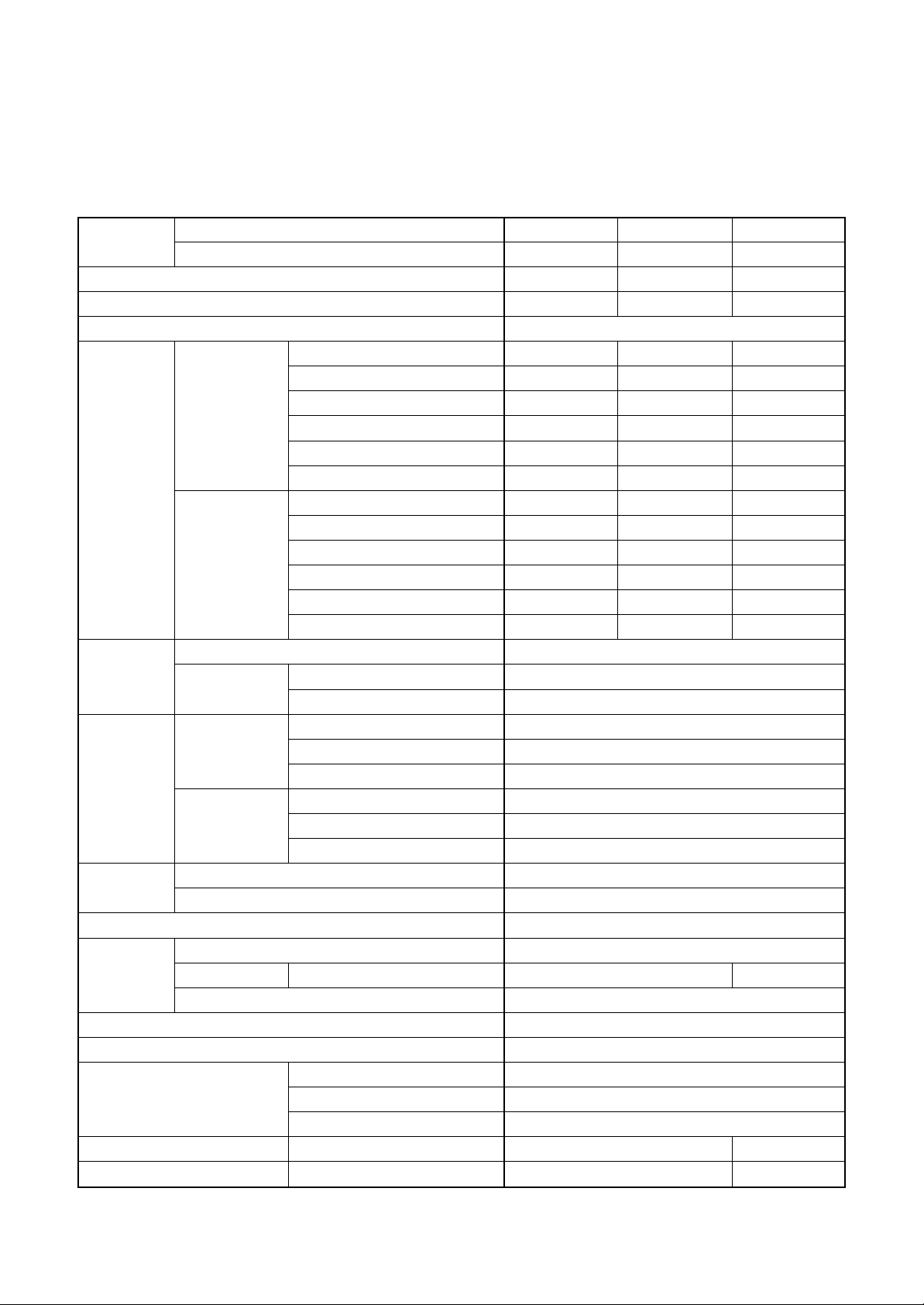
1-1-1. 4-Way Air Discharge Cassette Type
<Single type>
Model
Cooling capacity (kW)
Heating capacity (kW)
Pow er supply
Electrical
characteristics
Appearance
Outer
dimension
Total weight
Heat exchanger
Fan unit Standard air flow H/M/L (m³/min.)
Air filter
Controller (Sold separately)
Connecting pipe Liquid side (mm)
Sound pressure level H/M/L (dB•A)
Sound power level H/M/L (dB•A)
Indoor unit RA VOutdoor unit RA V-
Running current (A)
Power consumption (kW)
Cooling
Heating
Main unit
Ceiling panel
(Sold separately)
Main unit Width (mm)
Ceiling panel
(Sold separately)
Main unit (kg)
Ceiling panel (Sold separately) (kg)
Fan
Motor (W)
Power factor (%)
EER
Energy efficiency class ∗
Energy rating ∗∗
Running current (A)
Power consumption (kW)
Power factor (%)
COP
Energy efficiency class ∗
Energy rating ∗∗
Model
Panel color
Height (mm)
Depth (mm)
Height (mm)
Width (mm)
Depth (mm)
Gas side (mm)
Drain port (mm)
SM402MUT-E SM452MUT-E SM562MUT-E
SP404A T(Z, ZG)-E SP454AT(Z, ZG)-E SP562AT(Z, ZG)-E
3.6 4.0 5.0
4.0 4.5 5.6
1 phase 230V (220 – 240V) 50Hz
5.05 – 4.63 5.82 – 5.33 6.6 – 7.15
1.00 1.19 1.53
90 93 97
3.60 3.36 3.27
AAA
5.0 4.5 4.5
4.79 – 4.39 5.67 – 5.20 6.62 – 7.21
0.97 1.16 1.54
92 93 97
4.12 3.88 3.64
AAA
5.5 5.0 4.5
Zinc hot dipping steel plate
RBC-UM11PG (W)-E
Moon-white (Muncel 2.5GY 9.0/0.5)
268
575
575
27
700
700
17
3
Finned tube
Turbo fan
11.0 / 9.2 / 7.8 13.3 / 11.2 / 9.1
60
Long life filter
Remote controller
12.7
6.4
VP25
40 / 36 / 31 43 / 39 / 34
55 / 51 / 46 58 / 54 / 49
– 4 –
∗ : IEC standard, ∗∗ : AS standard
Page 5
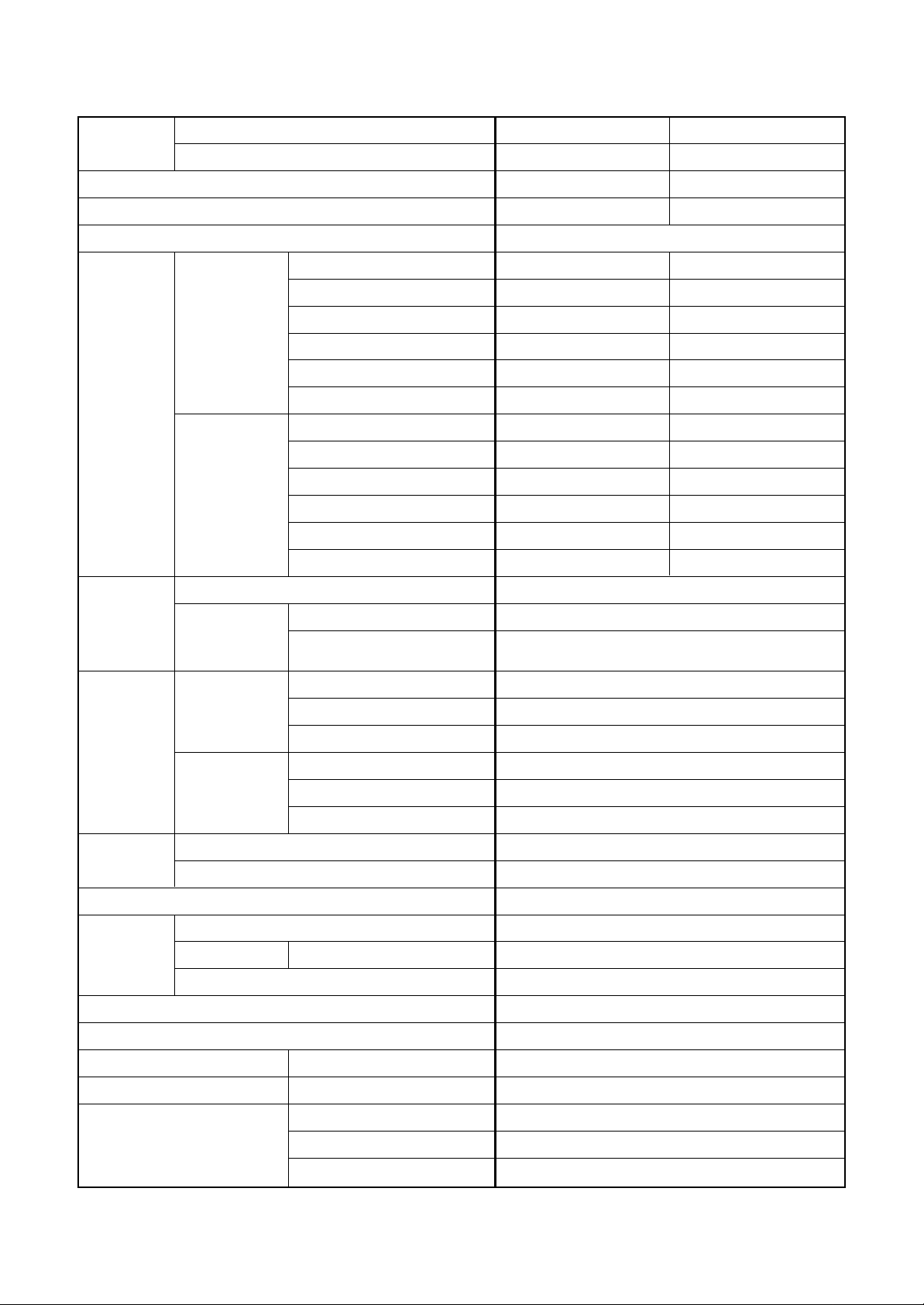
<Single type>
Model
Cooling capacity (kW)
Heating capacity (kW)
Pow er supply
Electrical
characteristics
Indoor unit RA VOutdoor unit RA V-
Running current (A)
Power consumption (kW)
Power factor (%)
Cooling
EER
Energy efficiency class ∗
Energy rating ∗∗
Running current (A)
Power consumption (kW)
Power factor (%)
Heating
COP
Energy efficiency class ∗
Energy rating ∗∗
SM562MUT-E SM562MUT-E
SM562AT-E SM563AT-E
5.0 5.0
5.6 5.6
1 phase 230V (220 – 240V) 50Hz
7.02 – 7.75 7.02 – 7.75
1.61 1.61
95 95
3.11 3.11
BB
4.0 4.0
7.04 – 7.72 7.04 – 7.72
1.61 1.61
95 95
3.48 3.48
BB
4.5 4.5
Main unit
Appearance
Outer
dimension
Total weight
Heat exchanger
Fan unit Standard air flow H/M/L (m³/min.)
Air filter
Controller (Sold separately)
Ceiling panel
(Sold separately)
Main unit Width (mm)
Ceiling panel
(Sold separately)
Main unit (kg)
Ceiling panel (Sold separately) (kg)
Fan
Motor (W)
Model
Panel color
Height (mm)
Depth (mm)
Height (mm)
Width (mm)
Depth (mm)
Zinc hot dipping steel plate
RBC-UM11PG (W)-E
Moon-white
(Muncel 2.5GY 9.0/0.5)
268
575
575
27
700
700
17
3
Finned tube
Turbo fan
13.3 / 11.2 / 9.1
60
Long life filter
Remote controller
Sound pressure level H/M/L (dB•A)
Sound power level H/M/L (dB•A)
Gas side (mm)
Connecting pipe Liquid side (mm)
Drain port (mm)
– 5 –
12.7
6.4
VP25
43 / 39 / 34
58 / 54 / 49
∗ : IEC standard, ∗∗ : AS standard
Page 6
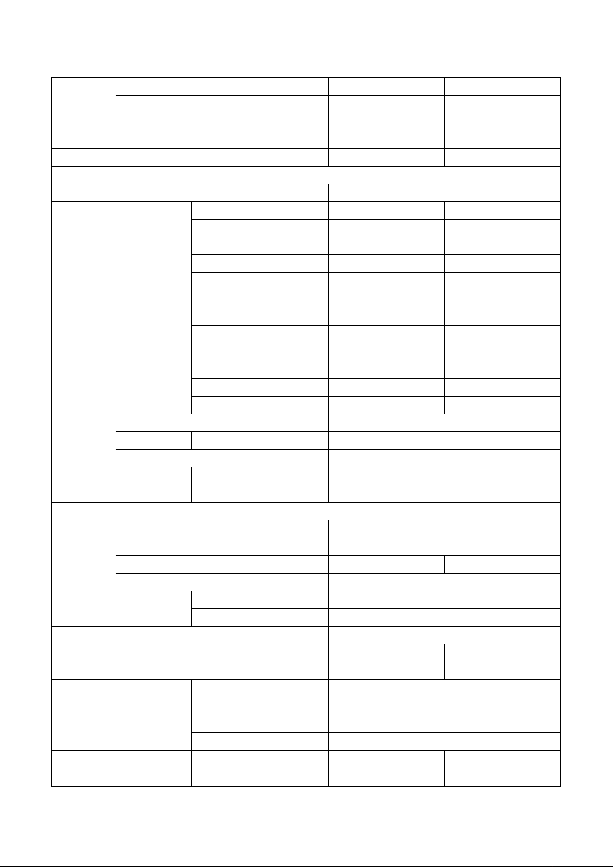
<Twin type>
Indoor unit 1 RA V- SM562MUT -E SM562MUT-E
Model Indoor unit 2 RA V- SM562MUT -E SM562MUT-E
Outdoor unit RAV- SP1102AT(Z, ZG)-E SP1104AT(Z, ZG)-E
Cooling capacity (kW) 10.0 10.0
Heating capacity (kW) 11.2 11.2
Indoor unit
Po w er supply 1 phase 230V (220 – 240V) 50Hz
Running current (A) 10.31 – 11.24 12.51 – 11.47
Pow er consumption (kW) 2.4 2.67
Cooling
Electrical
characteristics
Heating
Fan Turbo fan
Fan unit Standard air flow H/M/L (m³/min.) 13.3 / 11.2 / 9.1
Motor (W) 60
Sound pressure level H/M/L (dB•A) 43 / 39 / 34
Sound power lev el H/M/L (dB•A) 58 / 54 / 49
Po w er supply 1 phase 230V (220 – 240V) 50Hz
Pow er factor (%) 97 97
EER 4.17 3.75
Energy efficiency class ∗ AA
Energy rating ∗∗ ——
Running current (A) 10.95 – 11.95 12.51 – 11.47
Pow er consumption (kW) 2.55 2.67
Pow er factor (%) 97 97
COP 4.39 4.19
Energy efficiency class ∗ AA
Energy rating ∗∗ ——
Outdoor unit
Standard length (m) 7.5
Min. length (m) 5 3
Outer
dimension
Fan unit Standard air flow volume (m³/min.) 125 101
Connecting
pipe
Sound pressure level Cooling/Heating (dB•A) 49 / 51 49 / 50
Sound power lev el Cooling/Heating (dB•A) 66 / 68 66 / 67
Max. total length (m) 50
Height
difference
Fan Propeller fan
Motor (W) 63 + 63 100 + 100
Gas side
Liquid side
Outdoor lower (m) 30
Outdoor higher (m) 30
Main (mm) 15.9
Sub (mm) 12.7
Main (mm) 9.5
Sub (mm) 6.4
∗ : EC standard, ∗∗ : AS standard
– 6 –
Page 7
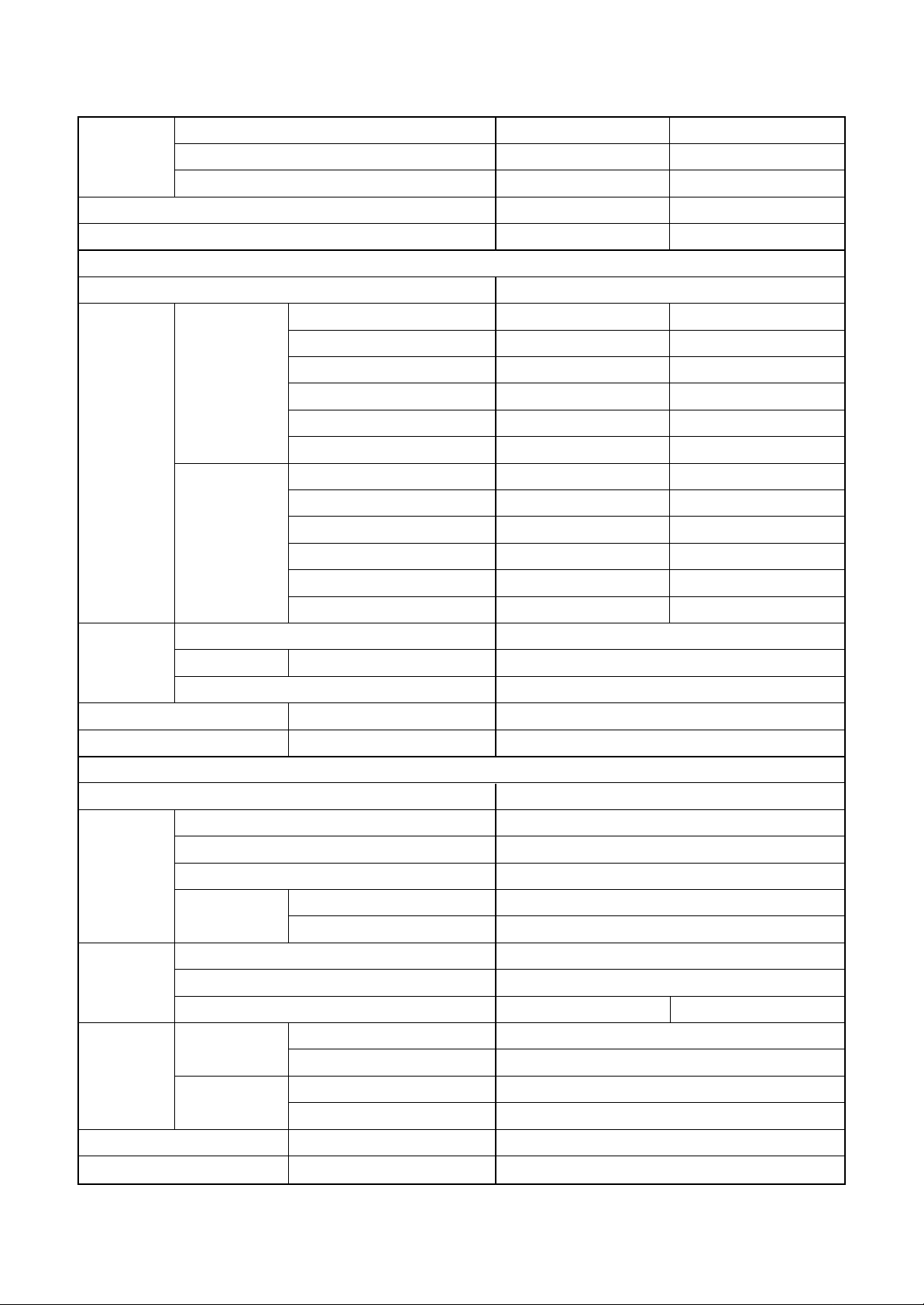
<Twin type>
Indoor unit 1 RA V- SM562MUT -E SM562MUT-E
Model Indoor unit 2 RA V- SM562MUT -E SM562MUT-E
Outdoor unit RA V- SM1102AT-E SM1103AT-E
Cooling capacity (kW) 10.0 10.0
Heating capacity (kW) 11.2 11.2
Indoor unit
Po w er supply 1 phase 230V (220 – 240V) 50Hz
Running current (A) 14.96 – 16.32 14.96 – 16.32
Pow er consumption (kW) 3.52 3.52
Cooling
Electrical
characteristics
Heating
Fan Turbo fan
Fan unit Standard air flow H/M/L (m³/min.) 13.3 / 11.2 / 9.1
Motor (W) 60
Sound pressure level H/M/L (dB•A) 43 / 39 / 34
Sound power lev el H/M/L (dB•A) 58 / 54 / 49
Po w er supply 1 phase 230V (220 – 240V) 50Hz
Pow er factor (%) 98 98
EER 2.84 2.84
Energy efficiency class ∗ CC
Energy rating ∗∗ ——
Running current (A) 13.35 – 14.56 13.35 – 14.56
Pow er consumption (kW) 3.14 3.14
Pow er factor (%) 98 98
COP 3.57 3.57
Energy efficiency class ∗ BB
Energy rating ∗∗ ——
Outdoor unit
Standard length (m) 7.5
Min. length (m) 5.0
Outer
dimension
Fan unit Standard air flow volume (m³/min.) 75
Connecting
pipe
Sound pressure level Cooling/Heating (dB•A) 53 / 54
Sound power lev el Cooling/Heating (dB•A) 70 / 71
Max. total length (m) 50
Height
difference
Fan Propeller fan
Motor (W) 100 63
Gas side
Liquid side
Outdoor lower (m) 30
Outdoor higher (m) 30
Main (mm) 15.9
Sub (mm) 12.7
Main (mm) 9.5
Sub (mm) 6.4
∗ : IEC standard, ∗∗ : AS standard
– 7 –
Page 8
<Triple type>
Indoor unit 1 RAV-SM562MUT-E
Model
Cooling capacity (kW) 14.0
Heating capacity (kW) 16.0
Power supply 1 phase 230V (220 – 240V) 50Hz
Electrical
characteristics
Indoor unit 2 RAV-SM562MUT-E
Indoor unit 3 RAV-SM562MUT-E
Outdoor unit RAV-SM1603AT-E
Indoor unit
Running current (A) 23.88 – 21.89
Power consumption (kW) 4.99
Cooling Power factor (%) 95
EER 2.81
Energy efficiency class ∗ C
Running current (A) 22.44 – 20.57
Power consumption (kW) 4.69
Heating Power factor (%) 95
COP 3.41
Energy efficiency class ∗ B
Fan Turbo fan
Fan unit Standard air flow H/M/L (m³/min.) 13.3 / 11.2 / 9.1
Motor (W) 60
Sound pressure level H/M/L (dB•A) 43 / 39 / 34
Sound power level H/M/L (dB•A) 58 / 54 / 49
Outdoor unit
Power supply 1 phase 230V (220 – 240V) 50Hz
Standard length (m) 7.5
Min. length (m) 5.0
Outer dimension Max. total length (m) 50
Height
difference
Fan Propeller fan
Fan unit Standard air flow volume (m³/min.) 103
Motor (W) 100 + 100
Gas side
Connecting pipe
Liquid side
Outdoor lower (m) 30
Outdoor higher (m) 30
Main (mm) 15.9
Sub (mm) 12.7
Main (mm) 9.5
Sub (mm) 6.4
Sound pressure level Cooling/Heating (dB•A) 51 / 53
Sound power level Cooling/Heating (dB•A) 68 / 70
– 8 –
∗ : IEC standard
Page 9
1-2. Outdoor Unit
<Super Digital Inverter>
Model name Outdoor unit RAV-SP
Power supply
Type
Compressor Motor (kW)
Pole
Refrigerant charged (kg)
Refrigerant control
Standard length (m)
Max. total length (m)
Inter Additional refrigerant charge
connecting pipe under long piping connector
Height
difference
Height (mm)
Outer dimension Width (mm)
Outdoor lower (m)
Outdoor higher (m)
562A T(Z)(ZG)-E 802AT(Z)(ZG)-E 1104AT(Z)(ZG)-E 1404AT(Z)(ZG)-E
1 phase 230V (220 – 240V) 50Hz
(Power exclusive to outdoor is required.)
Hermetic compressor
2 2 3.75 3.75
4444
1.5 2.1 3.1 3.1
Pulse motor valve
7.5 7.5 7.5 7.5
50 50 75 75
20g/m 40g/m 40g/m 40g/m
(21m to 50m) (31m to 50m) (31m to 75m) (31m to 75m)
30 30 30 30
30 30 30 30
795 795 1340 1340
900 900 900 900
Depth (mm)
Appearance
Total weight (kg)
Heat exchanger
Fan
Fan unit Standard air flow (m³/h)
Motor (W)
Gas side (mm)
Connecting pipe
Liquid side (mm)
Sound pressure level Cooling/Heating (dB•A)
Sound power level Cooling/Heating (dB•A)
Outside air temperature, Cooling (°C)
Outside air temperature, Heating (°C)
320 320 320 320
Silky shade (Muncel 1Y8.5/0.5)
55 62 93 93
Finned tube
Propeller fan
57 57 101 103
63 63 100 + 100 100 + 100
12.7 15.9 15.9 15.9
6.4 9.5 9.5 9.5
46 / 47 47 / 49 49 / 50 51 / 52
63 / 64 64 / 66 66 / 67 68 / 69
43 to –15°C
15 to –15°C 15 to –20°C
– 9 –
Page 10
Model name Outdoor unit
RAV-SP404AT(Z)(ZG)-E RAV-SP454AT(Z)(ZG)-E
Power supply
Type
Compressor Motor (kW)
Pole
Refrigerant charged (kg)
Refrigerant control
Standard length (m)
Max. total length (m)
Inter Additional refrigerant charge
connecting pipe under long piping connector
Height
difference
Height (mm)
Outer dimension Width (mm)
Depth (mm)
Outdoor lower (m)
Outdoor higher (m)
1 phase 230V (220 – 240V) 50Hz
(Power exclusive to outdoor is required.)
Hermetic compressor
1.1 1.1
44
1.0 1.0
Pulse motor valve
7.5 7.5
30 30
20g/m (21m to 30m)
30 30
30 30
550 550
780 780
290 290
Appearance
Total weight (kg)
Heat exchanger
Fan
Fan unit Standard air flow (m³/h)
Motor (W)
Gas side (mm)
Connecting pipe
Liquid side (mm)
Sound pressure level Cooling/Heating (dB•A)
Sound power level Cooling/Heating (dB•A)
Outside air temperature, Cooling (°C)
Outside air temperature, Heating (°C)
Silky shade (Muncel 1Y8.5/0.5)
40 40
Finned tube
Propeller fan
40 40
43 43
12.7 12.7
6.4 6.4
45 / 47 45 / 47
62 / 64 62 / 64
43 to –15°C
15 to –15°C
– 10 –
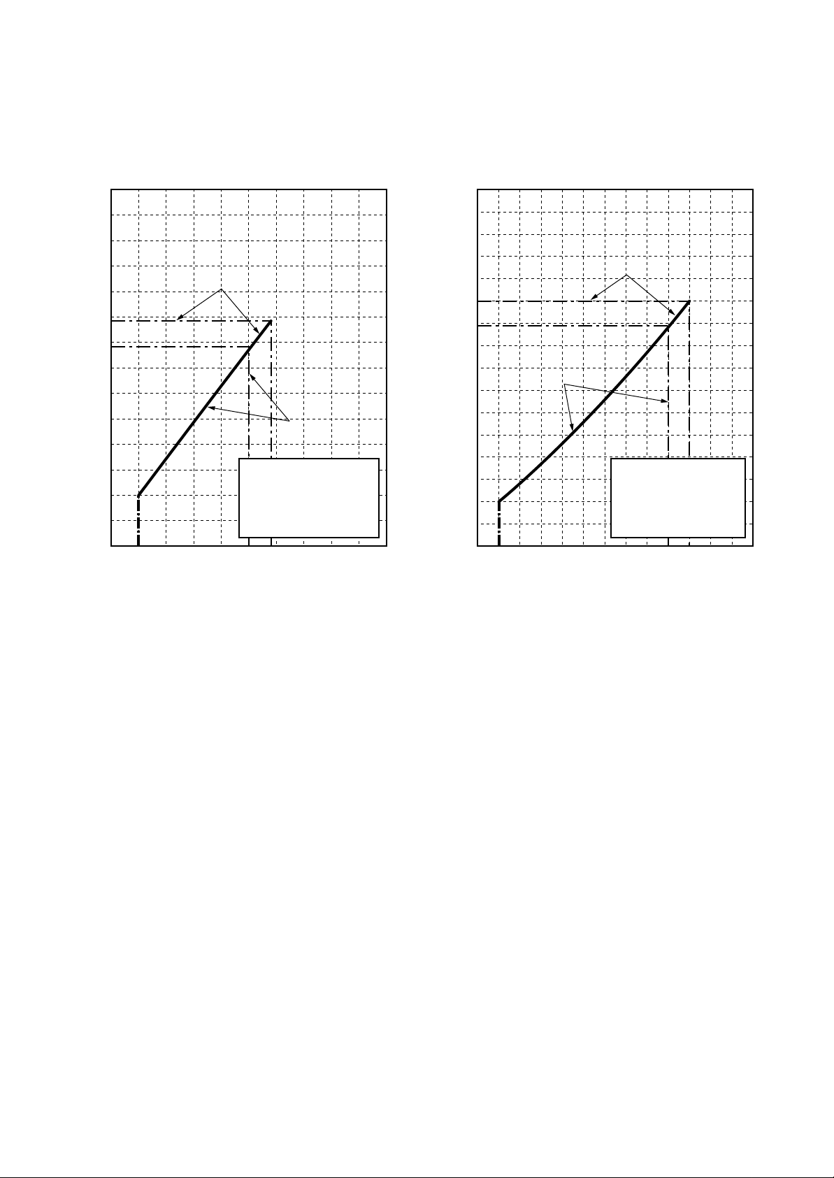
Page 11
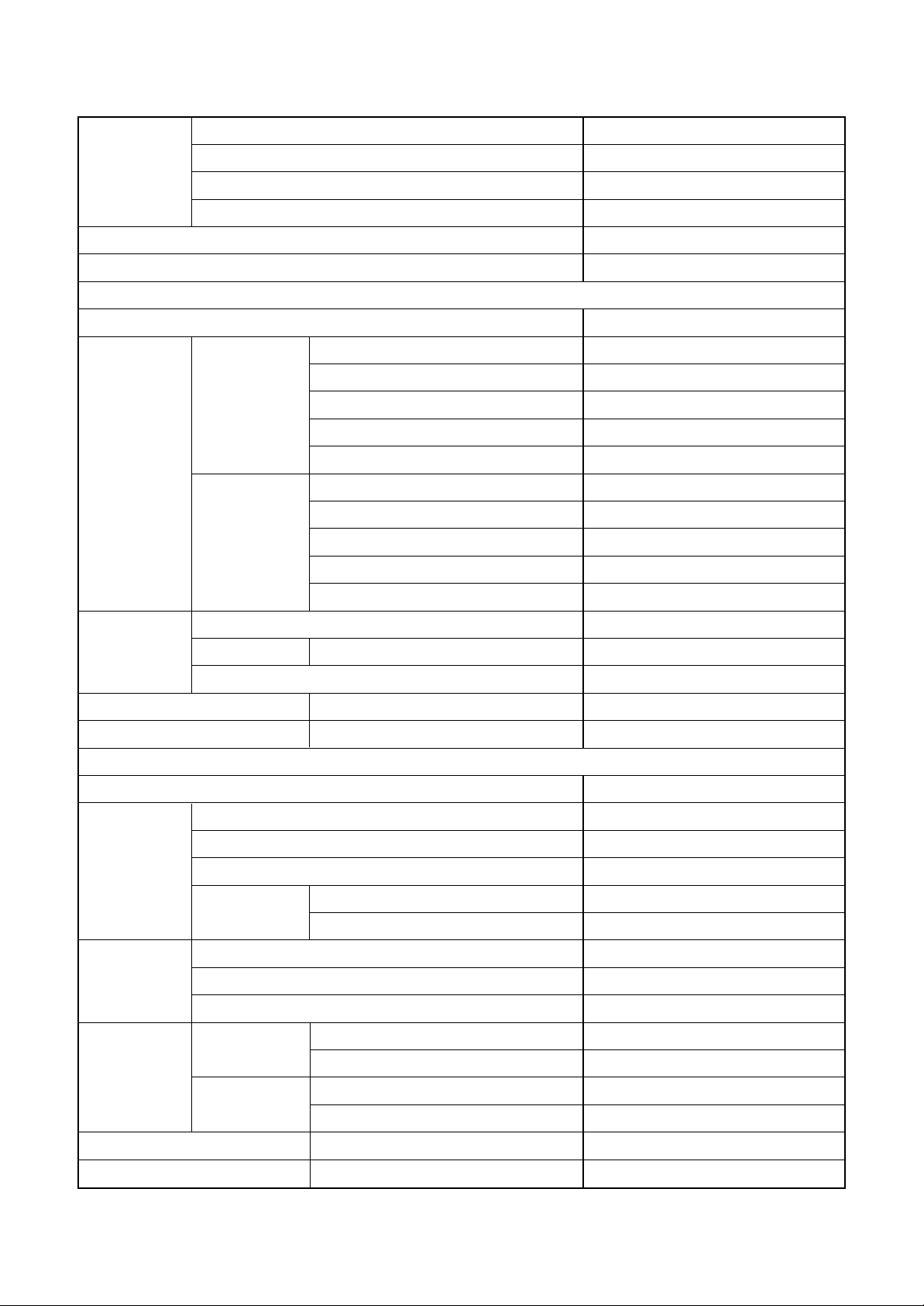
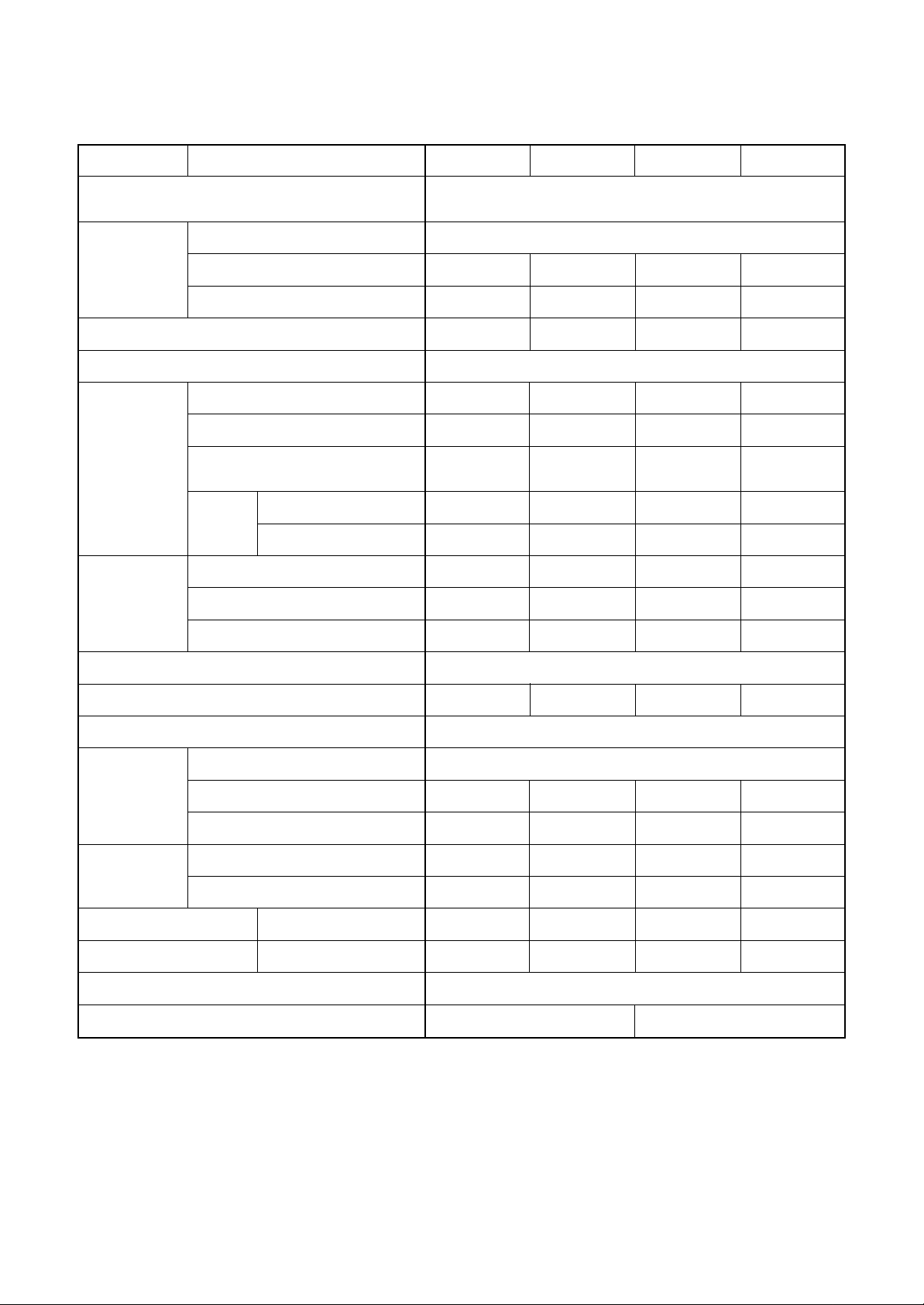
1-3. Operation Characteristic Curve
<Digital Inverter>
RAV-SM562MUT-E / RAV -SM562AT-E
<Cooling> <Heating>
10
8
6
4
Current (A)
2
0
0
• Conditions
Indoor : DB27˚C/WB19˚C
Outdoor : DB35˚C
Air flow : High
Pipe length : 7.5m
230V
20 40 60 70 80 100
Compressor speed (rps)
10
8
6
4
Current (A)
• Conditions
Indoor : DB20˚C
2
Outdoor : DB7˚C/WB6˚C
Air flow : High
Pipe length : 7.5m
230V
0
0 2040608090100
Compressor speed (rps)
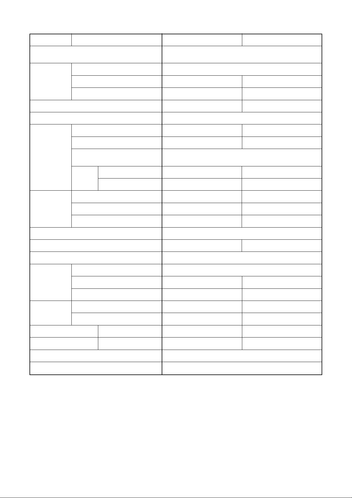
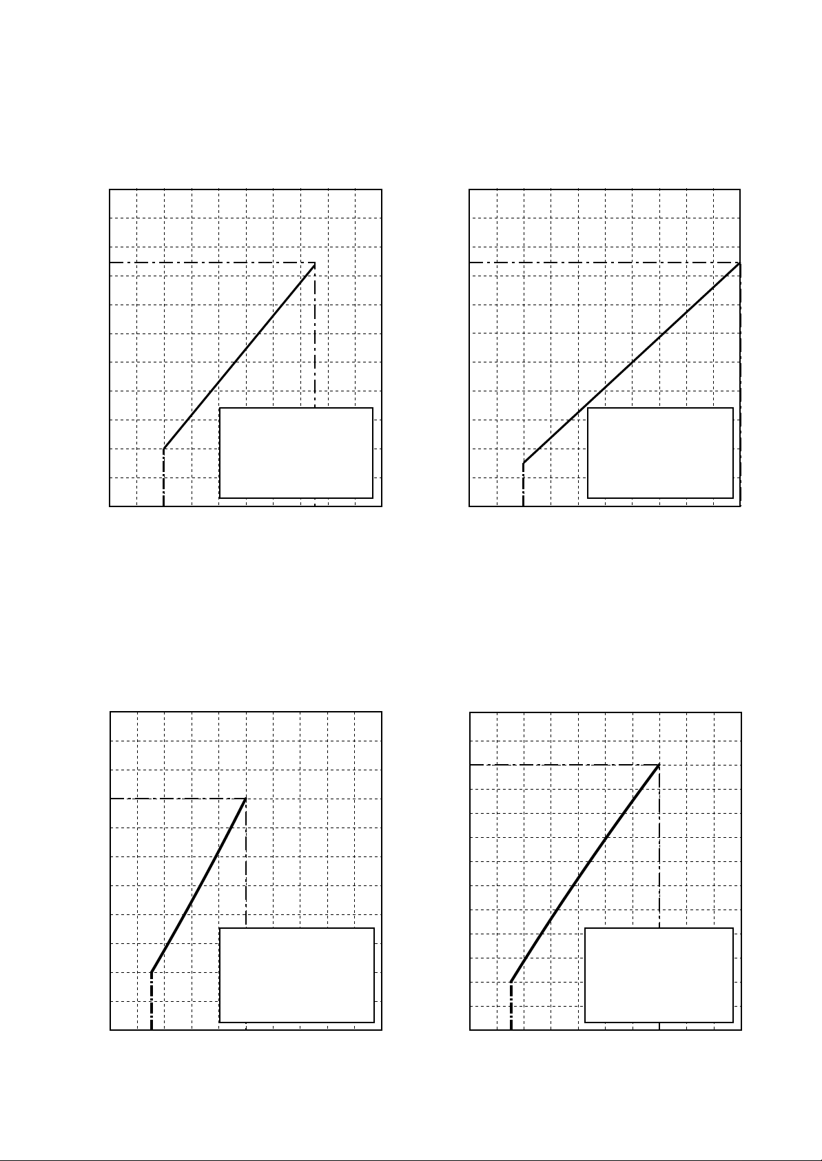
<Super Digital Inverter>
RAV-SM562MUT-E / RAV -SP562AT-E
<Cooling> <Heating>
10
12
10
8
8
6
6
Current (A)
Current (A)
4
• Conditions
Indoor : DB27˚C/WB19˚C
2
Outdoor : DB35˚C
Air flow : High
Pipe length : 7.5m
230V
0
0 20406050 70 80 100
4
2
0
0 204060 908070 100
• Conditions
Indoor : DB20˚C
Outdoor : DB7˚C/WB6˚C
Air flow : High
Pipe length : 7.5m
230V
Compressor speed (rps) Compressor speed (rps)
– 11 –
Page 12
<Super Digital Inverter>
SP40
SP40
SP45
SP45
RAV-SP404AT-E, RAV-SP404ATZ-E, RAV-SP404ATZG-E
RAV-SP454AT-E, RAV-SP454ATZ-E, RAV-SP454ATZG-E
<Cooling> <Heating>
14
12
SP45
10
8
6
Current (A)
4
2
0
0 20 405060708090100
SP45
• Conditions
Indoor : DB27˚C/WB19˚C
Outdoor : DB35˚C
Air flow : High
Pipe length : 7.5m
230V
SP40
SP40
Compressor speed (rps)
16
14
SP45
12
10
8
SP40
SP40
SP45
Current (A)
6
4
2
0
0 2040608090100120
• Conditions
Indoor : DB20˚C
Outdoor : DB7˚C/WB6˚C
Air flow : High
Pipe length : 7.5m
230V
Compressor speed (rps)
– 12 –
Page 13
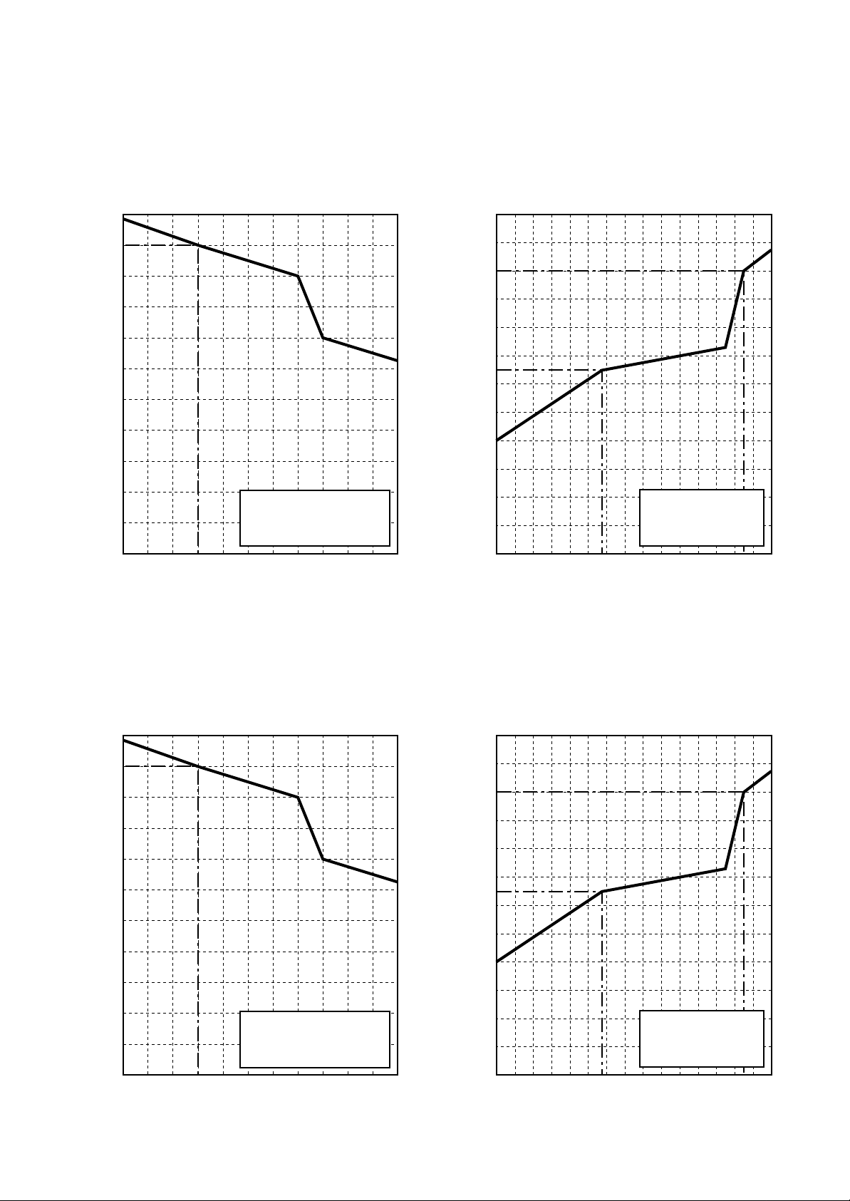
1-4. Capacity Variation Ratio According to Temperature
RAV-SP404AT-E, RAV-SP404ATZ-E, RAV-SP404ATZG-E
RAV-SP454AT-E, RAV-SP454ATZ-E, RAV-SP454ATZG-E
<Cooling> <Heating>
105
100
95
90
85
80
75
70
Capacity ratio (%)
65
60
55
50
32 33 34 35 36 37 38 39
Outdoor temp. (˚C)
• Conditions
Indoor : DB27˚C/WB19˚C
Indoor air flow : High
Pipe length : 7.5m
40
41 42 43
120
110
100
90
80
70
60
50
Capacity ratio (%)
40
30
20
10
0
-14-16-18-20 -12-10 -8 -6 -4 -2 0 2 4 6 8 10
• Conditions
Indoor : DB20˚C
Indoor air flow : High
Pipe length : 7.5m
Outdoor temp. (˚C)
RAV-SP562A T-E, RAV-SM563AT-E
<Cooling> <Heating>
105
100
95
90
85
80
75
70
Capacity ratio (%)
65
60
55
50
32 33 34 35 36 37 38 39
• Conditions
Indoor : DB27˚C/WB19˚C
Indoor air flow : High
Pipe length : 7.5m
40
41 42 43
120
110
100
90
80
70
60
50
Capacity ratio (%)
40
30
20
10
0
Outdoor temp. (˚C)
• Conditions
Indoor : DB20˚C
Indoor air flow : High
Pipe length : 7.5m
-14-16-18-20 -12-10 -8 -6 -4 -2 0 2 4 6 8 10
Outdoor temp. (˚C)
– 13 –
Page 14
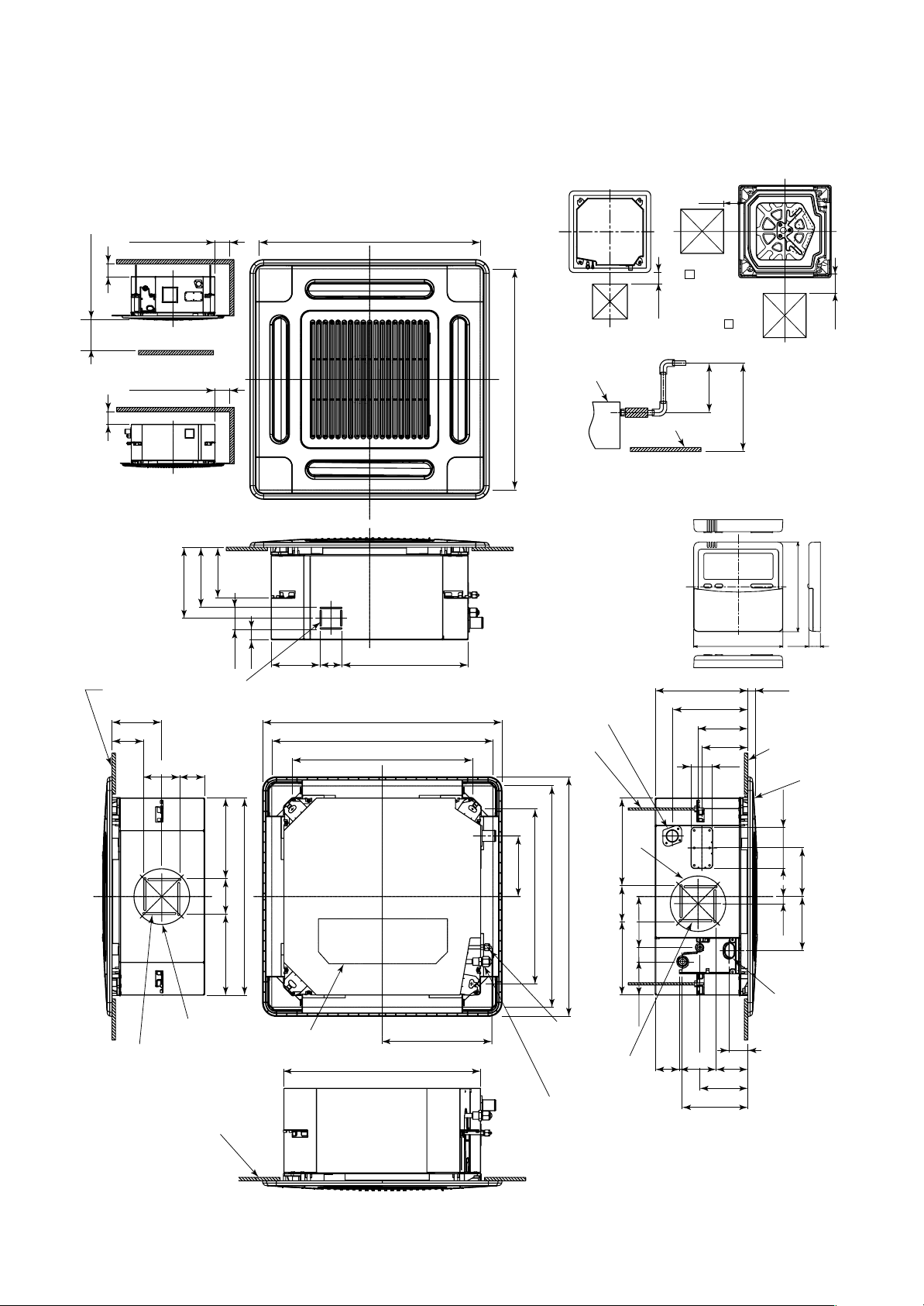
2-1. Indoor Unit
2. CONSTRUCTION VIEWS (EXTERNAL VIEWS)
200
1000 or more
15 or more15 or more
1000 or more
Obustacle
1000 or more
Space required for
installation and servicing
149
175
207
64
Bottom face
of ceiling
145.5
93
Knockout for flesh
air intake Ø100
70
105
595 to 660 Ceiling open dimension
142 64
29
700 Panel external dimension
595 to 660 Ceiling open dimension
525 Hanging bolt pitch
368.5
Check port
( 450)
Check port
( 450)
200
Check port
( 450)
Drain-up standing-up size
Indoor unit
627.5
or less
Stand-up
Bottom face
of ceiling
Stand-up
850 or less
Note)
595 to 660 Ceiling open dimension
As ABS is used for the drain discharge port of the main unit,
the vinyl chlor paste cannot be used.
Use the flexible hose (Band fix) included in the package.
• Wired remote controller
(RBC-AMT32E)
Drain discharge port
Hanging bolt
M10 or W3/8
local arrange
120
268 27
220.5
145.5
134
63
120
16
Bottom face
of ceiling
Ceiling panel
200
235
105235
Ø162
For branch duct knockout
square hole Ø150
Bottom face of ceiling
575 Unit external dimension
Electric parts box
320.5
575 Unit external dimension
– 14 –
Ø162
256
177
148
510 Hanging bolt pitch
700 Panel external dimension
595 to 660 Ceiling open dimension
Refrigerant pipe
(Liquid) Ø6.4
For branch ductt
knockout square
hole Ø150
Refrigerant pipe
(Gas) Ø12.7
214 105
97.5 42
139.5
190.5
120
142
21
158
Wiring
connection
port
55
9310570
Page 15
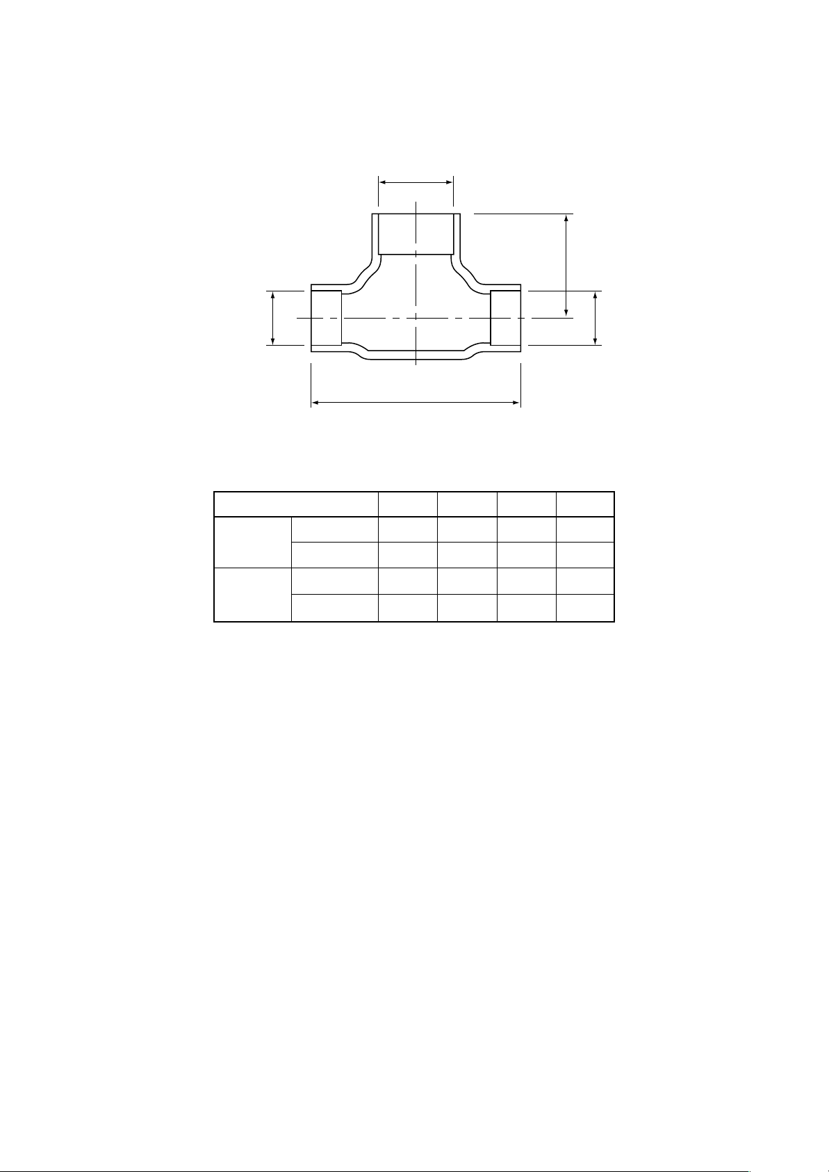
RBC-TWP30E2, RBC-TWP50E2 (Simultaneous Twin)
Inner diameter Ø C
B
Inner
diameter Ø D
Model (RBC-)
TWP30E2
TWP50E2
Liquid side
Gas side
Liquid side
Gas side
Inner
diameter Ø D
A
ABCD
36 14 Ø9.5 Ø6.4
43 23 Ø15.9 Ø12.7
34 14 Ø9.5 Ø9.5
44 21 Ø15.9 Ø15.9
– 15 –
Page 16
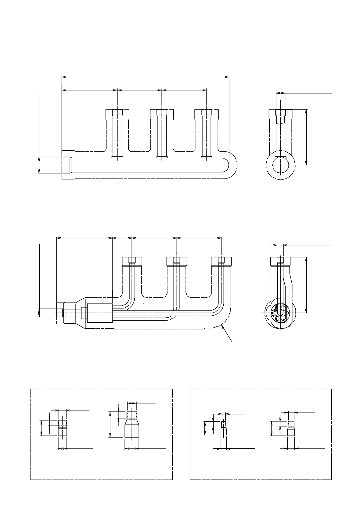
RBC-TRP100E (Simultaneous Triple)
<Gas side>
Header assembly
300
Inner diameter Ø25.4Inner diameter Ø12.7
<Liquid side>
Branch pipe assembly
35
80 80100
Inner diameter
Ø15.9
100
80 80100
Inner diameter
Ø9.52
Insulator
Gas side socket Liquid side socket
Ø15.9
28
10
Ø12.7
Ø15.9
(External
diameter)
46
12
6
24
Ø25.4
(External
diameter)
Ø6.4
Ø9.5
(External
diameter)
100
Ø9.5
9
26
Ø12.7
(External
diameter)
3 pcs. 3 pcs.1 pc. 1 pc.
– 16 –
Page 17
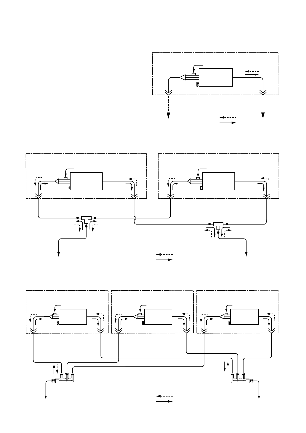
3. SYSTEMATIC REFRIGERATING CYCLE DIAGRAM
3-1. Indoor Unit
• Single type
(Combination of one indoor unit and
one outdoor unit)
Distributor
(Strainer
incorporated)
TC sensor
Refrigerant pipe
at liquid side
Outer diameter Ø6.4
Heating time
Cooling time
• Twin type (Combination of two indoor units and one outdoor unit)
RAV-SM562MUT-E RAV-SM562MUT-E
Distributor
(Strainer
incorporated)
TC sensor
Indoor A unit
TCJ sensor
Air heat
exchanger
Distributor
(Strainer
incorporated)
TC sensor
Indoor unit
TCJ sensor
Air heat
exchanger
Refrigerant pipe
at gas side
Outer diameter Ø12.7
To outdoor unitTo outdoor unit
Indoor B unit
TCJ sensor
Air heat
exchanger
Refrigerant pipe
at liquid side
Outer diameter Ø6.4
Branch pipe
Refrigerant pipeat liquid side
Outer diameter Ø9.5
To outdoor unit
Refrigerant pipe
at gas side
Outer diameter Ø12.7
Refrigerant pipe
at liquid side
Outer diameter Ø6.4
Refrigerant pipeat gas side
Outer diameter Ø15.9
Heating time
Cooling time
• Triple type (Combination of three indoor units and one outdoor unit)
RAV-SM562MUT-E
Distributor
(Strainer
incorporated)
TC sensor
Refrigerant pipe
at liquid side
Outer diameter
Ø6.4
Indoor A unit
TCJ sensor
exchanger
Air heat
Refrigerant pipe
at gas side
Outer diameter
Ø12.7
RAV-SM562MUT-E
Distributor
(Strainer
incorporated)
TC sensor
Refrigerant pipe
at liquid side
Outer diameter
Ø6.4
Indoor B unit
TCJ sensor
exchanger
Air heat
Refrigerant pipe
at gas side
Outer diameter
Ø12.7
RAV-SM562MUT-E
Distributor
(Strainer
incorporated)
TC sensor
Refrigerant pipe
at liquid side
Outer diameter
Ø6.4
Refrigerant pipe
at gas side
Outer diameter Ø12.7
Branch pipe
To outdoor unit
Indoor C unit
TCJ sensor
Air heat
exchanger
Refrigerant pipe
at gas side
Outer diameter
Ø12.7
Refrigerant
pipeat liquid side
Outer diameter Ø9.5
To outdoor unit
Distributor
Heating time
Cooling time
– 17 –
Distributor
Refrigerant
pipeat gas side
Outer diameter Ø15.9
To outdoor unit
Page 18
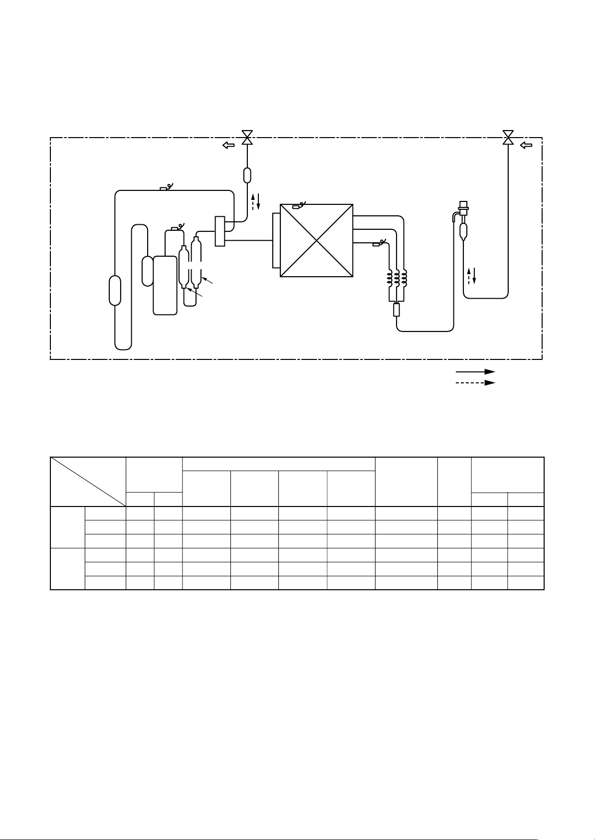
3-2. Outdoor Unit
RAV-SM562MUT-E / RAV -SP562AT-E
Accumulator
(1500cc)
TS sensor
TD sensor
Muffler
Ø25 × L160
Rotary compressor
(DA220A2F-20L)
Packed valve
Outer dia. Ø12.7
Strainer
4-way valve
(STF-0213Z)
Ø25 × L210
TO sensor
Heat exchangerØ8
1 row 30 stages
FP1.3 flat fin
Outdoor unit
TE
sensor
Packed valve
Outer dia. Ø6.4
Modulating
(PMV)
(SKV-18D26)
Capillary
Ø3×Ø2×
L530
PsPd
Strainer
R410A 1.5 kg
Cooling
Heating
Standard
Cooling Overload
Low load
Standard
Heating Overload
Low load
Pressure
(MPa)
Pd Ps
2.71 1.03
3.48 1.16
1.92 0.74
2.22 0.72
3.47 1.16
1.79 0.25
Pipe surface temperature (°C)
Discharge Suction
(TD) (TS) (TC) (TE)
75 15 10 38
81 20 16 51
34 5 2 11
62 6 38 2
81 20 55 15
71 –16 30 –18
Indoor heat Outdoor heat
exchanger exchanger
Compressor
revolutions per
second (rps)
∗∗
∗
∗∗
43
44
24
41
41
70
Indoor
fan
HIGH
HIGH
LOW
HIGH
LOW
HIGH
Indoor/Outdoor
temp. conditions
(DB/WB) (°C)
Indoor Outdoor
27/19 35/–
32/24 43/–
18/15.5 –5/–
20/– 7/6
30/– 24/18
15/–
–20/(70%)
∗ This compressor has 4-pole motor. The value when compressor frequency (Hz) is measured by a clamp
meter becomes 2 times of No. of compressor revolutions (rps).
– 18 –
Page 19
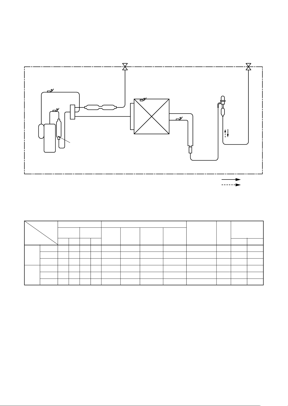
RAV-SM562MUT-E / RAV -SM562AT-E
TS sensor
TD sensor
Rotary compressor
(DA150A1F-20F)
2-step muffler
Ø19 .05 × 200L
4-way valve
(STF-0108Z)
Muffler
Ø19 × L160
Packed valve
Outer dia. Ø12.7
TO sensor
TE
sensor
Heat exchanger Ø8 ripple,
2 rows, 14 steps
FP1.3 flat fin
Outdoor unit
Packed valve
Outer dia. Ø6.4
PMV
(Pulse Motor Valve)
(CAM-B30YGTF-1)
Strainer
Distributor
R410A 1.0 kg
Cooling
Heating
Standard
Cooling Overload
Low load
Standard
Heating Overload
Low load
Pressure
(MPa) (kg/cm²G)
Pd Ps Pd Ps
3.50 0.97 35.7 9.9
3.90 1.08 39.8 11.0
1.90 0.70 19.4 7.1
2.31 0.61 13.6 6.2
2.86 0.89 29.2 9.1
1.86 0.25 19.0 2.6
Discharge Suction
Pipe surface temperature (°C)
Indoor heat Outdoor heat
exchanger exchanger
(TD) (TS) (TC) (TE)
85 14 12 48
93 26 17 54
48 7 5 30
87 5 40 1
86 17 47 11
69 –14 31 –15
Compressor
revolutions per
second (rps)
∗∗
∗
∗∗
70
70
50
97
95
98
Indoor
fan
HIGH
HIGH
LOW
HIGH
LOW
HIGH
Indoor/Outdoor
temp. conditions
(DB/WB) (°C)
Indoor Outdoor
27/19 35/–
32/24 43/–
18/15.5 –5/–
20/– 7/6
28/– 24/18
15/–
–10/(70%)
∗ This compressor has 4-pole motor. The value when compressor frequency (Hz) is measured by a clamp
meter becomes 2 times of No. of compressor revolutions (rps).
– 19 –
Page 20
RAV-SM402MUT-E / RAV -SP404AT-E
RAV-SM454MUT-E / RAV -SP454AT-E
TS sensor
TD sensor
(STF-0108Z)
Rotary compressor
(DA150A1F-20F)
2-step muffler
Ø19.05 × 200L
4-way valve
Muffler
Ø19 × L160
Packed valve
Outer dia. Ø12.7
TO sensor
TE
sensor
Heat exchanger Ø8 ripple,
2 rows, 14 steps
FP1.3 flat fin
Packed valve
Outer dia. Ø6.4
PMV
(Pulse Motor Valve)
(CAM-B30YGTF-2)
Strainer
Distributor
R410A 1.0 kg
Cooling
Heating
RAV-SP404AT-E
Standard
Cooling Overload
Low load
Standard
Heating Overload
Low load
Pressure
(MPa) (kg/cm²g)
Pd Ps Pd Ps
2.68 0.94 27.3 9.6
3.23 1.16 32.9 11.8
1.34 0.70 13.7 7.1
2.38 0.70 24.3 7.1
3.39 1.03 34.6 10.5
1.95 0.26 19.9 2.7
Discharge Suction
Pipe surface temperature (°C)
Indoor heat Outdoor heat
exchanger exchanger
(TD) (TS) (TC) (TE)
61 12 11 43
77 14 15 50
36 4 2 8
65 7 39 4
83 20 54 16
90 –17 32 –19
Compressor
drive revolution
frequency
(rps)
47
50
44
49
49
90
Indoor
fan
HIGH
HIGH
LOW
HIGH
LOW
HIGH
Indoor/Outdoor
temp. conditions
(DB/WB) (°C)
Indoor Outdoor
27/19 35/–
32/24 43/–
18/15.5 –5/–
20/– 7/6
30/– 24/18
15/––15/–
∗ This compressor has 4-pole motor. The value when compressor frequency (Hz) is measured by a clamp
meter becomes 2 times of No. of compressor revolutions (rps).
RAV-SP454AT-E
Standard
Cooling Overload
Low load
Standard
Heating Overload
Low load
Pressure
(MPa) (kg/cm²g)
Pd Ps Pd Ps
2.81 0.89 28.7 9.1
3.24 1.16 33.0 11.8
1.34 0.70 13.7 7.1
2.53 0.68 25.8 6.9
3.39 1.03 34.6 10.5
2.00 0.25 20.4 2.6
Discharge Suction
Pipe surface temperature (°C)
Indoor heat Outdoor heat
exchanger exchanger
(TD) (TS) (TC) (TE)
68 11 10 41
78 14 15 51
36 4 2 8
70 7 41 4
83 20 54 16
92 –17 33 –19
Compressor
drive revolution
frequency
(rps)
53
53
44
56
49
98
Indoor
fan
HIGH
HIGH
LOW
HIGH
LOW
HIGH
Indoor/Outdoor
temp. conditions
(DB/WB) (°C)
Indoor Outdoor
27/19 35/–
32/24 43/–
18/15.5 –5/–
20/– 7/6
30/– 24/18
15/––15/–
∗ This compressor has 4-pole motor. The value when compressor frequency (Hz) is measured by a clamp
meter becomes 2 times of No. of compressor revolutions (rps).
– 20 –
Page 21
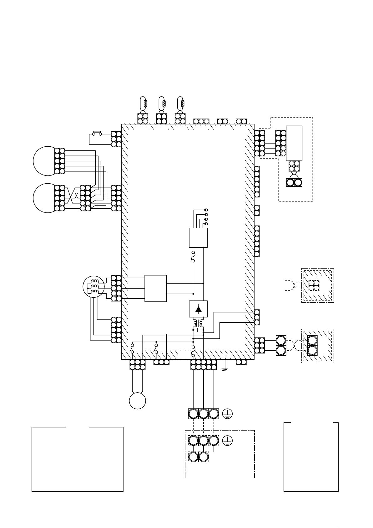
4. WIRING DIAGRAM
4-1. Indoor Unit
4-1-1. Compact 4-way Cassette Type
1 2
1 2
CN104
(YEL)
Control P.C. Board for
RY
302
1 233 1 2 3
1 2
LM1
LM2
5 5
4 4
3 3
2 2
1 1
5 5
4 4
3 3
2 2
1 1
5 5
4 4
3 3
2 2
1 1
FM
FS
CN34
(RED)
3 3
2 2
1 1
CN33
(WHI)
5 5
4 4
3 3
2 2
1 1
CN333
(WHI)
5 5
4 4
3 3
2 2
1 1
CN334
(WHI)
1 1
2 2
3 3
4 4
5 5
CN68
(BLU)
TA
TCJ
1 2
1 2
CN102
(RED)
1 2
1 2
CN101
(BLK)
MCC-1402
Indoor Unit
Fuse
F302
T3.15A
250V~
Motor
drive
circuit
RY
303
CN304
(GRY)
Fuse
F301
250V~
T6.3A
CN67
(BLK)
TC
1 2 3
CN80
(GRN)
Power
supply
circuit
+–
~~
1 233
1 2
WHI BLK
RED
DC20V
DC15V
DC12V
DC7V
5
445
(EXCT)
1 2
CN73
(RED)
P301
BLK
1 2
CN70
(WHI)
1 2
CN66
(WHI)
Connection interface (option)
CN50
(WHI)
(FAN DRIVE)
5
5
4
4
3
3
2
2
1
1
6
5
CN60
4
(WHI)
3
2
1
CN32
2
(WHI)
1
6
5
4
CN61
(YEL)
3
2
1
3
CN309
2
(YEL)
1
3
3
2 2
1 1
CN41
(BLU)
BLK
WHI
CN51
(RED)
5
5
4
4
P.C.
3
3
Board
2
2
1
1
1 2
1 2
Terminal for
central remote
controller
B
A
CN40
(BLU)
U4U3
BLK
WHI
2 2
1 1
CN001
(WHI)
Adapter for
Wireless Remote
Controller
BLK
B
A
WHI
Wired Renote
Controller
FM
TA
TC
TCJ
LM1,LM2
DP
FS
RY302
NOTE
: Fan motor
: Indoor temp. sensor
: Temp. sensor
: Temp. sensor
: Louver motor
: Drain pump motor
: Float switch
: Drain control relay
DP
Single phase
220 to 240V
50Hz
– 21 –
321
Indoor unit
earth screw
321
Outdoor unit
earth screw
Serial
NL
signal
Color
Identification
BLACK
:
BLK
BLUE
:
BLU
RED
:
RED
GRAY
:
GRY
PINK
:
PNK
GREEN
:
GRN
WHITE
:
WHI
BROWN
:
BRN
ORANGE
:
ORN
YELLOW
:
YEL
Page 22
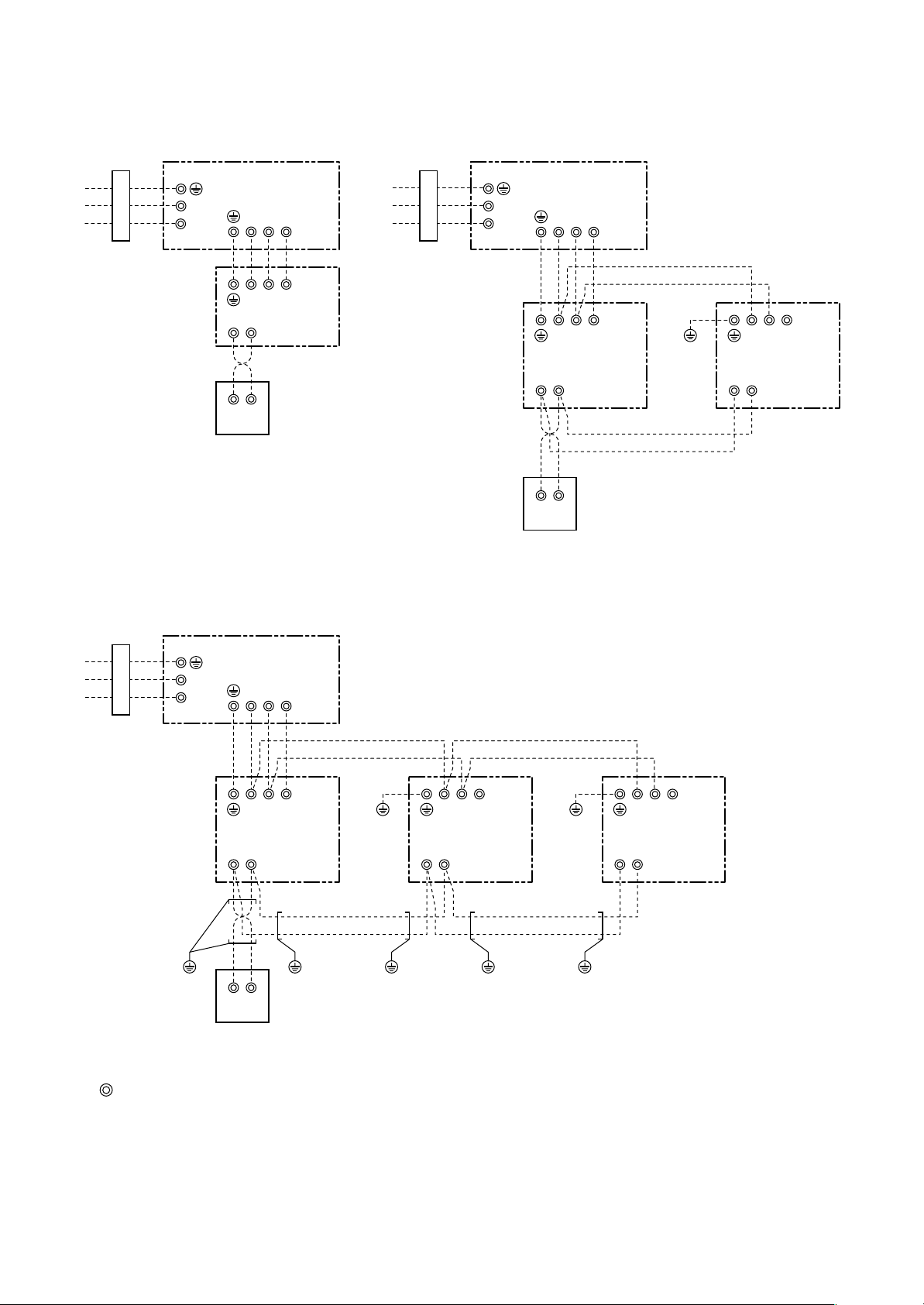
• Single type • Twin type
Power supply 220-240V
Single phase 50Hz
L
N
Wired remote controller
• Triple type
Outdoor unit
123
123
Indoor
B
A
AB
unit
Power supply 220-240V
Single phase 50Hz
L
N
Wired remote controller
Outdoor unit
123
123
Indoor unit
No.1 (Master)
B
A
AB
Earth
screw
123
Indoor unit
No.2 (Sub)
AB
Power supply 220-240V
Single phase 50Hz
L
N
Earth
screw
Wired remote controller
Outdoor unit
123
123
Indoor unit
No.1 (Header)
B
A
Earth
AB
screw
Earth
screw
Earth
screw
123
Indoor unit
No.2 (Follower)
AB
Earth
screw
Earth
screw
Earth
screw
123
Indoor unit
No.3 (Follower)
AB
Notes)
1. : indicates a terminal block
2. Broken line and chain line indicate wiring at local site.
3. For the inner wiring diagram of the outdoor unit and the indoor unit, refer to the wiring diagram of each model.
4. There is no polarity. It is no problem that the remote controller is connected to the indoor unit ter minal block A
and B reversely.
5. When using a wireless remote controller, connection of the remote controller to A and B terminal blocks are
unnecessary. (Wire connection between indoor unit No.1 and No.2 is necessary.)
– 22 –
Page 23
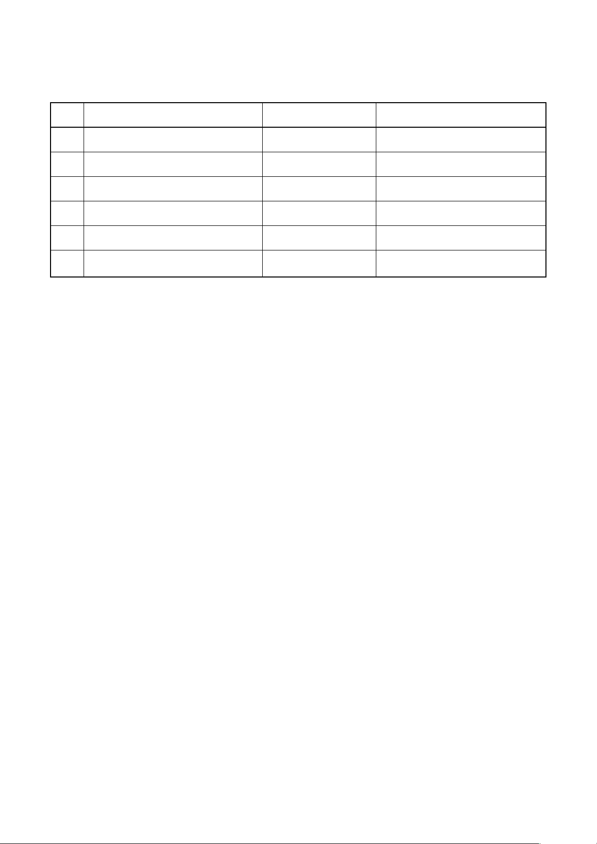
5-1. Indoor Unit
5. SPECIFICATIONS OF ELECTRICAL PARTS
No.
1
Fan motor (for indoor)
2
Thermo. sensor (TA-sensor)
3
Heat exchanger sensor (TCJ-sensor)
4
Heat exchanger sensor (TC-sensor)
5
Float switch
6
Drain pump motor
Parts name
Type
SWF-230-60-1R
155 mm
Ø6 mm, 1200 mm
Ø6 mm, 1200 mm
FS-0218-106
ADP-1406
Specifications
Output (Rated) 60 W, 220–240 V
10 kΩ at 25°C
10 kΩ at 25°C
10 kΩ at 25°C
– 23 –
Page 24

6. REFRIGERANT R410A
This air conditioner adopts the new refrigerant HFC
(R410A) which does not damage the ozone layer.
The working pressure of the new refrigerant R410A
is 1.6 times higher than conventional refrigerant
(R22). The refrigerating oil is also changed in
accordance with change of refrigerant, so be careful
that water , dust, and existing refrigerant or refrigerating oil are not entered in the refrigerant cycle of the
air conditioner using the new refrigerant during
installation work or servicing time.
The next section describes the precautions for air
conditioner using the new refrigerant. Conforming to
contents of the next section together with the
general cautions included in this manual, perform
the correct and safe work.
6-1. Safety During Installation/Servicing
As R410A’s pressure is about 1.6 times higher than
that of R22, improper installation/servicing may
cause a serious trouble. By using tools and materials exclusive for R410A, it is necessary to carry out
installation/servicing safely while taking the following
precautions into consideration.
1) Never use refrigerant other than R410A in an air
conditioner which is designed to operate with
R410A.
If other refrigerant than R410A is mixed, pressure
in the refrigeration cycle becomes abnormally
high, and it may cause personal injury, etc. by a
rupture.
2) Confirm the used refrigerant name, and use tools
and materials exclusive for the refrigerant R410A.
The refrigerant name R410A is indicated on the
visible place of the outdoor unit of the air conditioner using R410A as refrigerant. To prevent
mischarging, the diameter of the service port
differs from that of R22.
3) If a refrigeration gas leakage occurs during
installation/servicing, be sure to ventilate fully.
If the refrigerant gas comes into contact with fire,
a poisonous gas may occur.
4) When installing or removing an air conditioner, do
not allow air or moisture to remain in the refrigeration cycle. Otherwise, pressure in the refrigeration cycle may become abnormally high so
that a rupture or personal injury may be caused.
5) After completion of installation work, check to
make sure that there is no refrigeration gas
leakage.
If the refrigerant gas leaks into the room, coming
into contact with fire in the fan-driven heater,
space heater, etc., a poisonous gas may occur.
6) When an air conditioning system charged with a
large volume of refrigerant is installed in a small
room, it is necessary to exercise care so that,
even when refrigerant leaks, its concentr ation
does not exceed the marginal le vel.
If the refrigerant gas leakage occurs and its
concentration exceeds the marginal le vel, an
oxygen starvation accident ma y result.
7) Be sure to carry out installation or removal
according to the installation manual.
Improper installation may cause refrigeration
trouble, water leakage , electric shock, fire, etc.
8) Unauthorized modifications to the air conditioner
may be dangerous. If a breakdown occurs please
call a qualified air conditioner technician or
electrician.
Improper repair’s may result in water leakage,
electric shock and fire, etc.
6-2. Refrigerant Piping Installation
6-2-1. Piping Materials and Joints Used
For the refrigerant piping installation, copper pipes
and joints are mainly used. Copper pipes and joints
suitable for the refrigerant m ust be chosen and
installed. Furthermore, it is necessary to use clean
copper pipes and joints whose interior surfaces are
less affected by contaminants .
1) Copper Pipes
It is necessary to use seamless copper pipes
which are made of either copper or copper alloy
and it is desirable that the amount of residual oil
is less than 40 mg/10 m. Do not use copper
pipes having a collapsed, deformed or discolored
portion (especially on the interior surface).
Otherwise, the expansion valve or capillary tube
may become blocked with contaminants.
As an air conditioner using R410A incurs pressure higher than when using R22, it is necessary
to choose adequate materials.
Thicknesses of copper pipes used with R410A
are as shown in Table 6-2-1. Never use copper
pipes thinner than 0.8 mm even when it is
available on the market.
– 24 –
Page 25
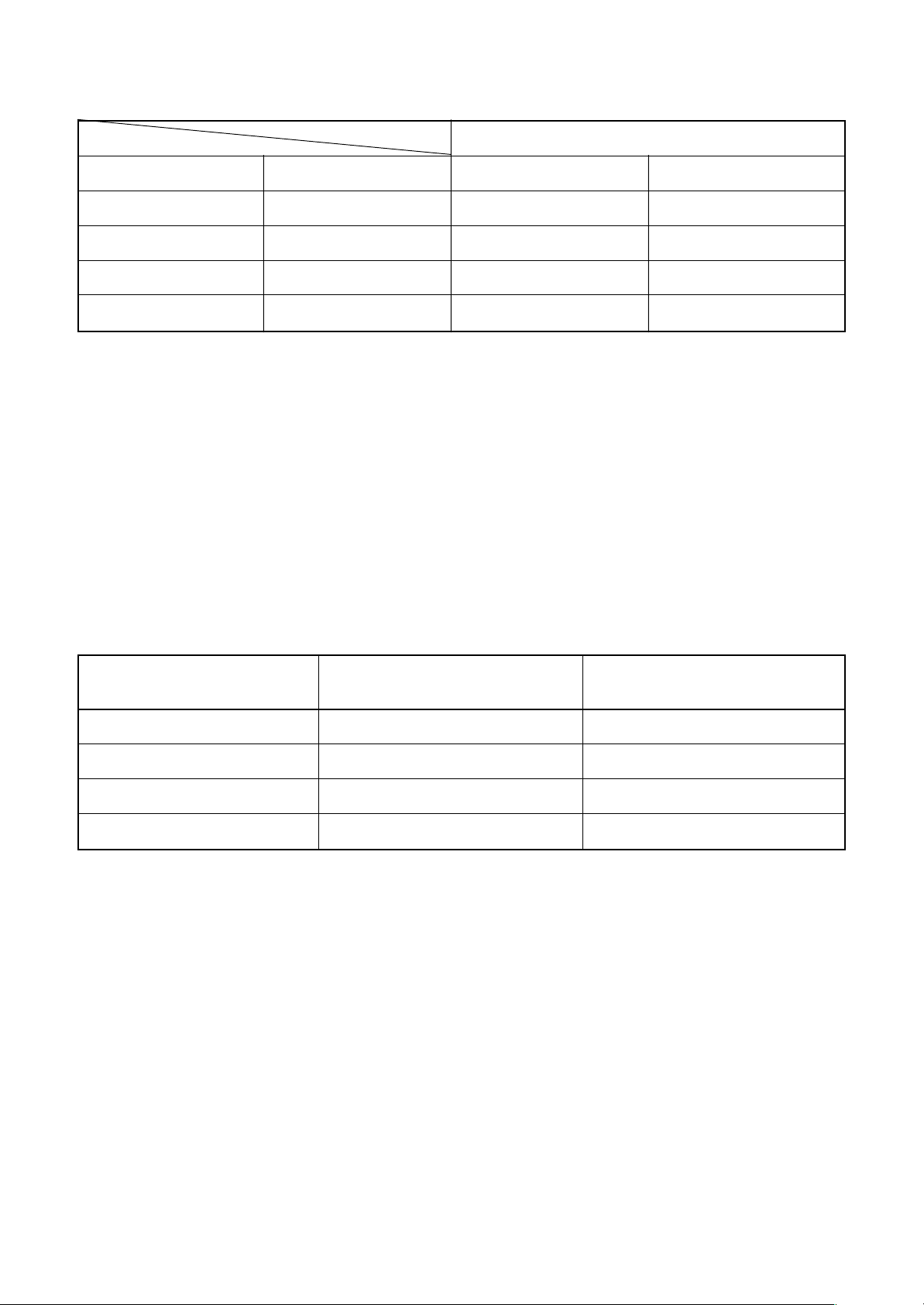
Table 6-2-1 Thicknesses of annealed copper pipes
Thickness (mm)
Nominal diameter
1/4
3/8
1/2
5/8
2) Joints
For copper pipes, flare joints or socket joints are used. Prior to use, be sure to remove all contaminants.
a) Flare Joints
Flare joints used to connect the copper pipes cannot be used for pipings whose outer diameter exceeds
20 mm. In such a case, socket joints can be used.
Sizes of flare pipe ends, flare joint ends and flare nuts are as shown in Tables 6-2-3 to 6-2-6 below .
b) Socket Joints
Socket joints are such that they are brazed for connections, and used mainly for thic k pipings whose
diameter is larger than 20 mm.
Thicknesses of sock et joints are as shown in Table 6-2-2.
Outer diameter (mm)
6.35
9.52
12.70
15.88
R410A R22
0.80 0.80
0.80 0.80
0.80 0.80
1.00 1.00
Table 6-2-2 Minimum thicknesses of socket joints
Nominal diameter
1/4
3/8
1/2
5/8
Reference outer diameter of
copper pipe jointed (mm)
6.35
9.52
12.70
15.88
Minimum joint thickness
(mm)
0.50
0.60
0.70
0.80
6-2-2. Processing of Piping Materials
When performing the refrigerant piping installation, care should be taken to ensure that water or dust does not
enter the pipe interior, that no other oil other than lubricating oils used in the installed air conditioner is used,
and that refrigerant does not leak. When using lubricating oils in the piping processing, use such lubricating oils
whose water content has been removed. When stored, be sure to seal the container with an airtight cap or any
other cover.
1) Flare Processing Procedures and Precautions
a) Cutting the Pipe
By means of a pipe cutter, slowly cut the pipe so that it is not deformed.
b) Removing Burrs and Chips
If the flared section has chips or burrs, refrigerant leakage may occur.
Carefully remove all burrs and clean the cut surface before installation.
– 25 –
Page 26
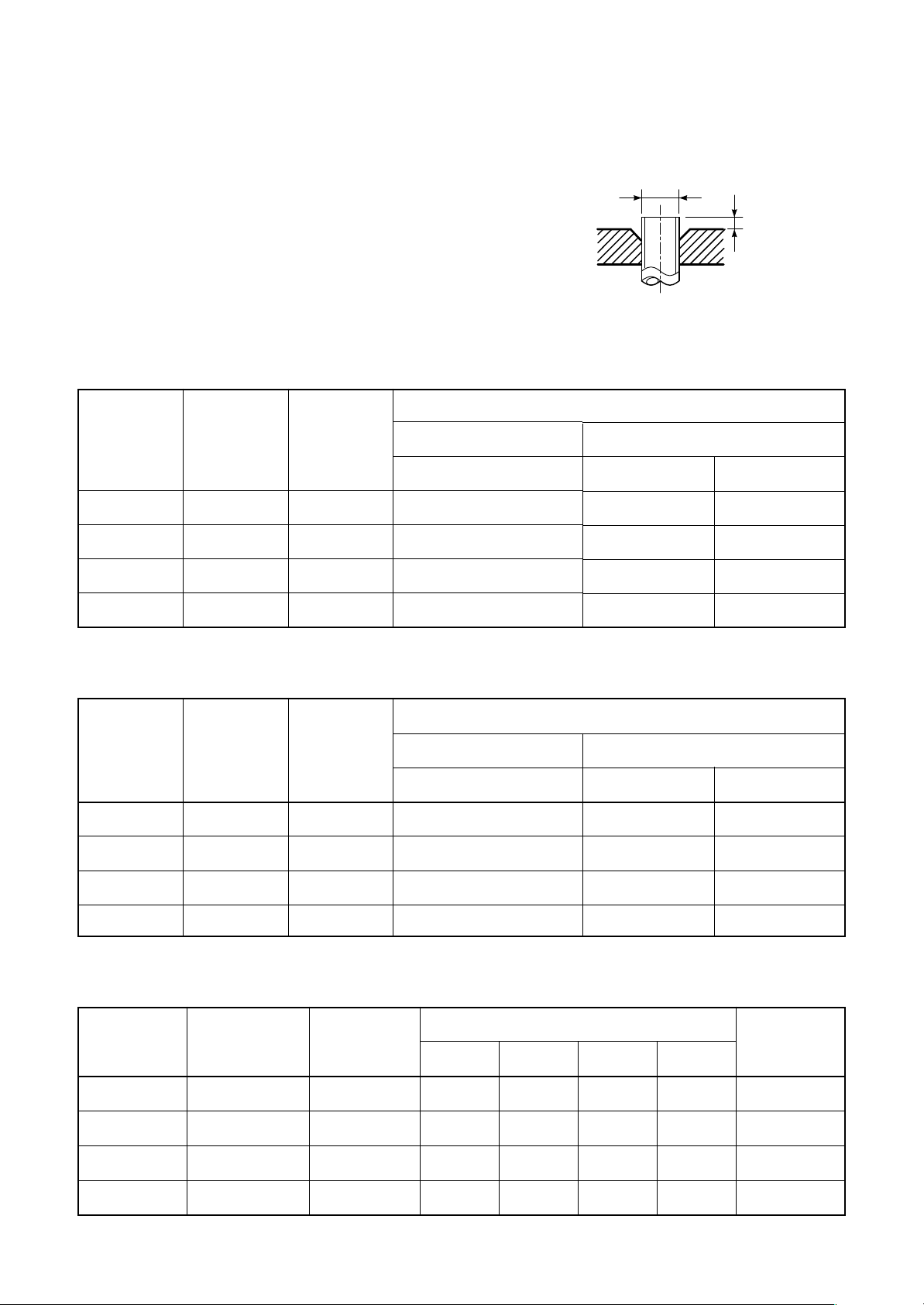
c) Insertion of Flare Nut
d) Flare Processing
Make certain that a clamp bar and copper
pipe have been cleaned.
By means of the clamp bar, perform the flare
processing correctly.
Use either a flare tool for R410A or conventional flare tool.
Table 6-2-3 Dimensions related to flare processing for R410A
Nominal
diameter
Outer
diameter
(mm)
Thickness
(mm)
Flare processing dimensions differ according
to the type of flare tool. When using a conventional flare tool, be sure to secure “dimension
A” b y using a gauge for size adjustment.
Fig. 6-2-1 Flare pr ocessing dimensions
Flare tool for
R410A clutch type
ØD
A
A (mm)
Conventional flare tool
Clutch type Wing nut type
1/4
3/8
1/2
5/8
Nominal
diameter
1/4
3/8
1/2
5/8
6.35
9.52
12.70
15.88
0.8
0.8
0.8
1.0
0 to 0.5
0 to 0.5
0 to 0.5
0 to 0.5
Table 6-2-4 Dimensions related to flare processing for R22
Outer
diameter
(mm)
Thickness
(mm)
Flare tool for
R22 clutch type
6.35
9.52
12.70
15.88
0.8
0.8
0.8
1.0
0 to 0.5
0 to 0.5
0 to 0.5
0 to 0.5
1.0 to 1.5 1.5 to 2.0
1.0 to 1.5 1.5 to 2.0
1.0 to 1.5 2.0 to 2.5
1.0 to 1.5 2.0 to 2.5
A (mm)
Conventional flare tool
Clutch type Wing nut type
0.5 to 1.0 1.0 to 1.5
0.5 to 1.0 1.0 to 1.5
0.5 to 1.0 1.5 to 2.0
0.5 to 1.0 1.5 to 2.0
Nominal
diameter
1/4
3/8
1/2
5/8
Table 6-2-5 Flare and flare nut dimensions for R410A
Outer diameter
(mm)
6.35
9.52
12.70
15.88
Thickness
(mm)
0.8
0.8
0.8
1.0
Dimension (mm)
ABCD
9.1 9.2 6.5 13
13.2 13.5 9.7 20
16.6 16.0 12.9 23
19.7 19.0 16.0 25
– 26 –
Flare nut
width (mm)
17
22
26
29
Page 27
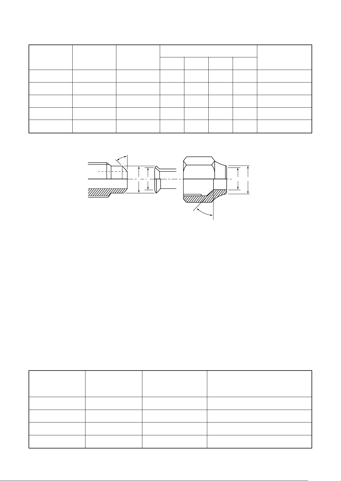
Table 6-2-6 Flare and flare nut dimensions for R22
Nominal
diameter
1/4
3/8
1/2
5/8
3/4
Outer diameter
(mm)
6.35
9.52
12.70
15.88
19.05
Thickness
45˚to 46˚
(mm)
0.8
0.8
0.8
1.0
1.0
B A
Dimension (mm)
ABCD
9.0 9.2 6.5 13
13.0 13.5 9.7 20
16.2 16.0 12.9 20
19.4 19.0 16.0 23
23.3 24.0 19.2 34
D
C
43˚to 45˚
Flare nut width
(mm)
17
22
24
27
36
Fig. 6-2-2 Relations between flare nut and flare seal surface
2) Flare Connecting Procedures and Precautions
a) Make sure that the flare and union portions do not have any scar or dust, etc.
b) Correctly align the processed flare surface with the union axis.
c) Tighten the flare with designated torque by means of a torque wrench. The tightening torque for R410A is
the same as that for conventional R22. Incidentally, when the torque is weak, the gas leakage may occur.
When it is strong, the flare nut may crack and may be made non-removable. When choosing the tightening
torque, comply with values designated b y manufacturers. Table 6-2-7 shows reference values.
Note)
When applying oil to the flare surface, be sure to use oil designated by the manufacturer.
If any other oil is used, the lubricating oils may deteriorate and cause the compressor to burn out.
Table 6-2-7 Tightening torque of flare for R410A [Reference values]
Nominal
diameter
1/4
Outer diameter
(mm)
6.35
Tightening torque
N•m (kgf•cm)
14 to 18 (140 to 180)
Tightening torque of torque
wrenches available on the market
N•m (kgf•cm)
16 (160), 18 (180)
3/8
1/2
5/8
9.52
12.70
15.88
33 to 42 (330 to 420)
50 to 62 (500 to 620)
63 to 77 (630 to 770)
– 27 –
42 (420)
55 (550)
65 (650)
Page 28
6-3. Tools
6-3-1. Required T ools
The service port diameter of packed valve of the outdoor unit in the air conditioner using R410A is changed to
prev ent mixing of other refrigerant. To reinforce the pressure-resisting strength, flare processing dimensions and
opposite side dimension of flare nut (For Ø12.7 copper pipe) of the refrigerant piping are lengthened.
The used refrigerating oil is changed, and mixing of oil may cause a trouble such as generation of sludge,
clogging of capillary, etc. Accordingly, the tools to be used are classified into the following three types.
1) Tools exclusive for R410A (Those which cannot be used for conventional refrigerant (R22))
2) Tools exclusive for R410A, but can be also used for con ventional refrigerant (R22)
3) Tools commonly used for R410A and f or conventional refrigerant (R22)
The table below shows the tools exclusive for R410A and their interchangeability.
Tools exclusive for R410A (The following tools for R410A are required.)
Tools whose specifications are changed for R410A and their interchangeability
No.
Used tool
Flare tool
Copper pipe gauge for
adjusting projection
margin
Torque wrench
Gauge manifold
Charge hose
V acuum pump adapter
Electronic balance for
refrigerant charging
Refrigerant cylinder
Leakage detector
Charging cylinder
Usage
Pipe flaring
Flaring by conventional
flare tool
Connection of flare nut
Evacuating, refrigerant
charge, run check, etc.
V acuum evacuating
Refrigerant charge
Refrigerant charge
Gas leakage check
Refrigerant charge
air conditioner installation
Existence of
new equipment
for R410A
Yes
Yes
Yes
Yes
Yes
Yes
Yes
Yes
(Note 2)
R410A
Whether conventional equipment
can be used
*(Note 1)
*(Note 1)
×
×
×
×
×
×
×
Conventional air
conditioner installation
Whether new equipment
can be used with
conventional refrigerant
¡
*(Note 1)
×
×
¡
¡
×
¡
×
Note 1) When flaring is carried out for R410A using the conventional flare tools, adjustment of projection
margin is necessary. For this adjustment, a copper pipe gauge , etc. are necessary.
Note 2) Charging cylinder for R410A is being currently developed.
General tools (Conventional tools can be used.)
In addition to the above exclusive tools, the following equipments which serve also for R22 are necessary
as the general tools.
1) V acuum pump
Use vacuum pump by
attaching vacuum pump adapter.
2) Torque wrench
3) Pipe cutter
4) Reamer
5) Pipe bender
6) Level vial
7) Screwdriver (+, –)
8) Spanner or Monkey wrench
9) Hole core drill (Ø65)
10) Hexagon wrench
(Opposite side 4mm)
11) Tape measure
12) Metal saw
Also prepare the following equipments for other installation method and run check.
1) Clamp meter
2) Thermometer
3) Insulation resistance tester
4) Electroscope
– 28 –
Page 29
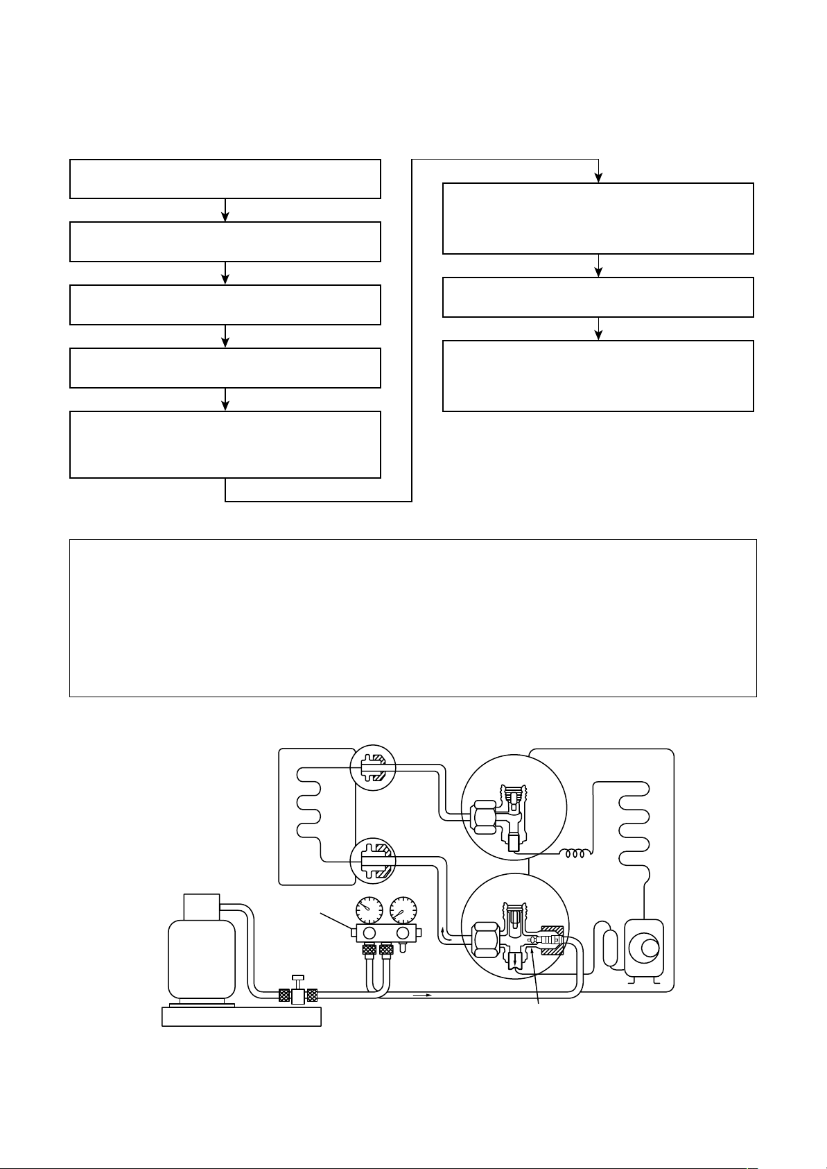
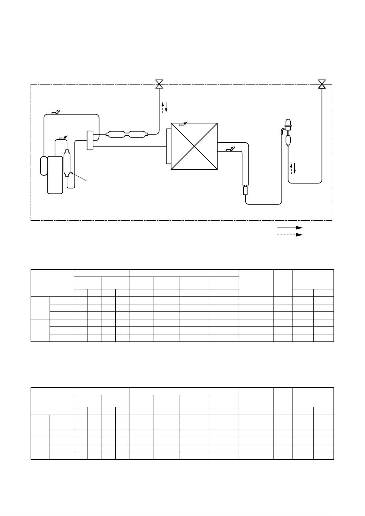
6-4. Recharging of Refrigerant
When it is necessary to recharge refrigerant, charge the specified amount of new refrigerant according to the
following steps .
Recover the refrigerant, and check no refrigerant
remains in the equipment.
Connect the charge hose to packed valve service
port at the outdoor unit’s gas side.
When the compound gauge’s pointer has indicated
–0.1 Mpa (–76 cmHg), place the handle Low in the
fully closed position, and turn off the vacuum pump’s
power switch.
Connect the charge hose of the vacuum pump
adapter.
Open fully both packed valves at liquid and gas
sides.
Place the handle of the gauge manifold Low in the
fully opened position, and turn on the vacuum pump’s
power switch. Then, evacuating the refrigerant in the
cycle.
Never charge refrigerant exceeding the specified amount.
If the specified amount of refrigerant cannot be charged, charge refrigerant bit by bit in COOL mode.
Do not carry out additional charging.
Keep the status as it is for 1 to 2 minutes, and ensure
that the compound gauge’s pointer does not return.
Set the refrigerant cylinder to the electronic balance,
connect the connecting hose to the cylinder and the
connecting port of the electronic balance, and charge
liquid refrigerant.
(For refrigerant charging, see the figure below.)
When additional charging is carried out if refrigerant leaks, the refrigerant composition changes in the
refrigeration cycle, that is characteristics of the air conditioner changes, refrigerant exceeding the
specified amount is charged, and working pressure in the refrigeration cycle becomes abnormally high
pressure, and may cause a rupture or personal injury.
(INDOOR unit)
Refrigerant cylinder
(With siphon pipe)
Check valve
Open/Close valve
for charging
Electronic balance for refrigerant charging
Fig. 6-4-1 Configuration of refrigerant charging
(Liquid side)
(Gas side)
– 29 –
(OUTDOOR unit)
Opened
Closed
Service port
Page 30
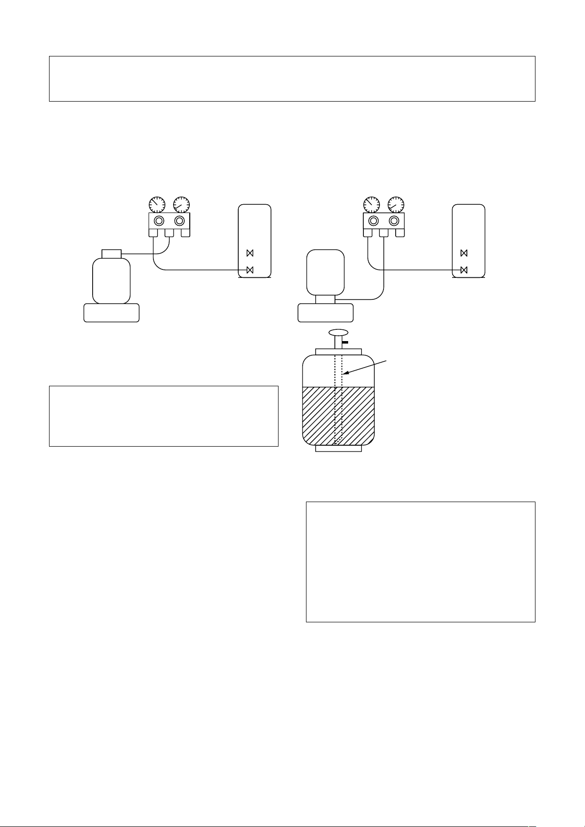
Be sure to make setting so that liquid can be charged.
When using a cylinder equipped with a siphon, liquid can be charged without turning it upside down.
It is necessary for charging refrigerant under condition of liquid because R410A is mixed type of refrigerant.
Accordingly, when charging refrigerant from the refrigerant cylinder to the equipment, charge it turning the
cylinder upside down if cylinder is not equipped with siphon.
[ Cylinder with siphon ] [ Cylinder without siphon ]
Refrigerant
cylinder
Gauge manifold
OUTDOOR unit
cylinder
Refrigerant
Gauge manifold
OUTDOOR unit
Electronic
balance
R410A refrigerant is HFC mixed refrigerant.
Therefore, if it is charged with gas, the composition of the charged refrigerant changes and the
characteristics of the equipment varies.
6-5. Brazing of Pipes
6-5-1. Materials for Brazing
1) Silver brazing filler
Silver brazing filler is an allo y mainly composed
of silver and copper. It is used to join iron, copper
or copper alloy, and is relatively expensive though
it excels in solderability.
2) Phosphor bronze brazing filler
Phosphor bronze brazing filler is generally used
to join copper or copper alloy.
Fig. 6-4-2
6-5-2. Flux
Electronic
balance
Siphon
Phosphor bronze brazing filler tends to react
with sulfur and produce a fragile compound
water solution, which may cause a gas
leakage. Therefore, use any other type of
brazing filler at a hot spring resort, etc., and
coat the surface with a paint.
When performing brazing again at time of
servicing, use the same type of brazing filler.
3) Low temperature brazing filler
Low temperature brazing filler is generally called
solder, and is an alloy of tin and lead. Since it is
weak in adhesive strength, do not use it for
refrigerant pipes.
1) Reason why flux is necessary
• By removing the oxide film and any foreign
matter on the metal surface, it assists the flow
of brazing filler .
• In the brazing process, it prevents the metal
surface from being oxidized.
• By reducing the brazing filler's surface tension,
the brazing filler adheres better to the treated
metal.
– 30 –
Page 31

Nitrogen gas
cylinder
Pipe
Flow meter
M
Stop valve
From Nitrogen cylinder
Nitrogen
gas
Rubber plug
2) Characteristics required for flux
• Activated temperature of flux coincides with the
brazing temperature.
• Due to a wide effective temperature range, flux
is hard to carbonize.
• It is easy to remove slag after brazing.
• The corrosive action to the treated metal and
brazing filler is minimum.
• It excels in coating performance and is harmless to the human body.
As the flux works in a complicated manner as
described above, it is necessary to select an
adequate type of flux according to the type and
shape of treated metal, type of brazing filler and
brazing method, etc.
3) Types of flux
• Noncorrosive flux
Generally, it is a compound of borax and boric
acid.
It is effective in case where the brazing temperature is higher than 800°C.
• Activated flux
Most of fluxes generally used for silver brazing
are this type.
It features an increased o xide film removing
capability due to the addition of compounds
such as potassium fluoride, potassium chloride
and sodium fluoride to the borax-boric acid
compound.
4) Piping materials for brazing and used brazing filler/flux
6-5-3. Brazing
As brazing work requires sophisticated techniques,
experiences based upon a theoretical knowledge, it
must be performed by a person qualified.
In order to prev ent the oxide film from occurring in
the pipe interior during brazing, it is effective to
proceed with brazing while letting dry Nitrogen gas
(N2) flow.
Never use gas other than Nitrogen gas.
(1) Brazing method to prevent oxidation
Attach a reducing valve and a flow-meter to
the Nitrogen gas cylinder.
Use a copper pipe to direct the piping mate-
rial, and attach a flow-meter to the cylinder.
Apply a seal onto the clearance between the
piping material and inserted copper pipe for
Nitrogen in order to prev ent backflow of the
Nitrogen gas.
When the Nitrogen gas is flowing, be sure to
keep the piping end open.
Adjust the flow rate of Nitrogen gas so that it
is lower than 0.05 m³/Hr or 0.02 MPa (0.2kgf/
cm²) by means of the reducing valve.
After performing the steps above, keep the
Nitrogen gas flowing until the pipe cools
down to a certain extent (temperature at
which pipes are touchable with hands).
Remove the flux completely after brazing.
Copper - Copper
Piping
material
Copper - Iron
Iron - Iron
Do not enter flux into the refrigeration cycle.
When chlorine contained in the flux remains
within the pipe, the lubricating oil deteriorates.
Therefore, use a flux which does not contain
chlorine.
When adding water to the flux, use water
which does not contain chlorine (e.g. distilled
water or ion-exchange water).
Remove the flux after brazing.
Used brazing
filler
Phosphor copper
Silver
Silver
Used
flux
Do not use
Paste flux
V apor flux
Fig. 6-5-1 Prevention of oxidation during brazing
– 31 –
Page 32

6-6. Tolerance of Pipe Length and Pipe Head
n Twin system
Refrigerant pipe
specification
Pipe length
(one way)
Height
difference
Total length (L + a or L + b)
Branch pipe length (a, b)
Maximum difference between indoor units
(b – a, or a - b)
Between indoor units ( ∆ h)
Between indoor unit When outdoor unit heigher (H)
and outdoor unit When outdoor unit lower (H)
Number of bent portions
Indoor unit A
Indoor unit B
50 m
15 m
10 m
0.5 m
30 m
30 m
10 m or less
∆h
Distributor
b
Branch pipeaBranch pipe
H
L
Main pipe
Outdoor unit
CAUTION
When planning a layout for Units A and B, comply with the following:
1. The lengths after branching (“a” and “b”) should be equal if feasible.
Install Units A and B so that the difference of the branching lengths becomes less than 10m if the lengths
cannot be equal due to the branch pipe position.
2. Install Units A and B on the same level.
If Units A and B cannot be installed on the same lev el, the difference in level should be limited to 0.5m or less.
3. Be certain to install Units A and B in the same room.
Units A and B cannot be operated independently each other.
– 32 –
Page 33

n Triple system
Refrigerant pipe
specification
Total length (L + a, L +b, L+c)
Pipe length
(one way)
Height
difference
Between indoor unit When outdoor unit heigher (H)
and outdoor unit When outdoor unit lower (H)
Number of bent portions
Branch pipe length (a, b, c)
Maximum difference between indoor units
(|a – b|, |b – c|, |c – d|)
Between indoor units ( ∆ h)
Indoor unit C Indoor unit B
Branch pipe Branch pipe
50 m
15 m
10 m
0.5 m
30 m
30 m
10 m or less
Indoor unit A
∆ h
b
Branch pipe
ca
Distributor
L
Main pipe
Outdoor unit
CAUTION
When planning a layout for Units A, B and C, comply with the following:
1. The lengths after branching (“a” and “b”, “b” and “c”, “a” and “c”) should be equal if feasible.
Install Units A, B and C so that the difference of the branching lengths becomes less than 10m if the
lengths cannot be equal due to the branch pipe position.
2. Install Units A, B and C on the same level.
If Units A, B and C cannot be installed on the same level, the difference in level should be limited to 0.5 m
or less.
3. Be certain to install Units A and B and C in the same room. Units A, B and C cannot be operated independently each other.
H
– 33 –
Page 34

6-7. Additional Refrigerant Amount
n Twin system
<Formula for Calculating Additional Refrigerant Amount>
Do not remove the refrigerant even if the additional refrigerant amount becomes minus result as a result of
calculations by the following formula and operate the air conditioner as it is.
Additional refrigerant amount (kg) = Main piping additional refrigerant amount (kg)
+ Branch piping additional refrigerant amount (kg)
αα
=
α × (L – 18) +
αα
αα
α : Additional refrigerant amount per meter of actual main piping length (kg)
αα
γγ
γ : Additional refrigerant amount per meter of actual branch piping length (kg)
γγ
L : Actual length of main piping (m)
a, b : Actual length of branch piping (m)
γγ
γ × (a + b – 4)
γγ
Standard piping length
Main piping Branch piping
18 m 2 m
Connecting pipe diameter
Lab
Ø9.5 Ø6.4 Ø6.4
Indoor unit B
Distributor
b
Branch pipeaBranch pipe
Additional refrigerant amount per Meter (kg/m)
αα
α
αα
0.040 — 0.020
Indoor unit A
∆h
ββ
β
ββ
H
γγ
γ
γγ
L
Main pipe
Outdoor unit
CAUTION
1. Be certain to wire the additional refrigerant amount, pipe length (actual length), head and other
specification on the nameplate put on the outdoor unit for recording.
2. Seal the correct amount of additional refrigerant in the system.
– 34 –
Page 35

n Triple system
<Formula for Calculating Additional Refrigerant Amount>
Do not remove the refrigerant even if the additional refrigerant amount becomes minus result as a result of
calculations by the following formula and operate the air conditioner as it is.
Additional refrigerant amount (kg) = Main piping additional refrigerant amount (kg)
+ Branch piping additional refrigerant amount (kg)
αα
={
α × (L – 28)} + {
αα
αα
α : Additional refrigerant amount per meter of actual main piping length (kg)
αα
γγ
γ : Additional refrigerant amount per meter of actual branch piping length (kg)
γγ
L : Actual length of main piping (m)
a, b, c : Actual length of branch piping (m)
γγ
γ × (a + b + c – 6)}
γγ
Connecting pipe diameter
Labc
Ø9.5 Ø6.4 Ø6.4 Ø6.4
Indoor unit C Indoor unit B
Branch pipe Branch pipe
b
ca
Additional refrigerant amount per Meter (kg/m)
αα
α
αα
0.04 — 0.02
ββ
β
ββ
Indoor unit A
Branch pipe
γγ
γ
γγ
∆ h
H
Distributor
L
Main pipe
Outdoor unit
CAUTION
1. Be certain to wire the additional refrigerant amount, pipe length (actual length), head and other
specification on the nameplate put on the outdoor unit for recording.
2. Seal the correct amount of additional refrigerant in the system.
– 35 –
Page 36

6-8. Piping Materials and Sizes
n Twin system
Use copper tube of Copper and copper alloy seamless pipes and tubes, with 40mg/10m or less in the
amount of oil stuck on inner walls of pipe and 0.8mm in pipe wall thickness for diameters for diameters 6.4,
9.5 and 12.7mm and 1.0mm, for diameter 15.9mm. Never use pipes of thin wall thickness such as 0.7mm.
In parentheres ( ) are wall thickness
Gas side
Main pipe
Branch pipe
Pipe side
Main pipe
Liquid side
Branch pipe
Ø15.9 (1.0)
Ø12.7 (0.8)
Ø9.5 (0.8)
Ø6.4 (0.8)
n Triple system
Use copper tube of Copper and copper alloy seamless pipes and tubes, with 40 mg/10 m or less in the
amount of oil stuck on inner walls of pipe and 0.8 mm in pipe wall thickness for diameters 6.4, 9.5 and
12.7 mm and 1.0 mm, for diameter 15.9 mm. Never use pipes of thin wall thickness such as 0.7 mm.
<Between outdoor unit and distributor> [Unit: mm]
Outdoor unit
Main pipe
Gas side
Liquid side
∗ ( ): Pipe wall thickness
<Between distributor and indoor unit> [Unit: mm]
Ø15.9 (1.0)
Ø9.5 (0.8)
Indoor unit
Branch pipe
∗ ( ): Pipe wall thickness
Gas side
Liquid side
SM56 type
Ø12.7 (0.8)
Ø6.4 (0.8)
– 36 –
Page 37

6-9. Branch Pipe
n Twin system
Now the refrigerant pipe is installed using branch pipes supplied as accessories.
• Bend and adjust the refrigerant piping so that the branch pipes and pipe after branching become horizontal.
• Fix the branch pipes onto a wall in a ceiling or onto a column.
• Provide a straight pipe longer than 500mm in length as the main piping of the branches.
OK OK
Horizontal
more
500mm or
Horizontal
NO GOOG NO GOOG
Inclination
6-10. Distributor
n Triple system
Now the refrigerant pipe is installed using distributor supplied as accessories.
• Bend and adjust the refrigerant piping so that the distributor and pipe after branching become horizontal.
• Fix the distributor onto a wall in a ceiling or onto a column.
• Provide a straight pipe longer than 500 mm in length as the main piping of the branches.
Inclination
<How to install distributor>
Branch pipes are horizontal
and collective pipes are vertical
Branch pipes and
collective pipes are horizontal
Branch pipe Branch pipe
<Gas pipe side> <Liquid pipe side>
Branch pipes are horizontal
and collective pipes are vertical
Branch pipes and
collective pipes are horizontal
Collective pipeCollective pipe
<Restrictions in length of the straight area of the branch pipe (main pipe side)>
Provide a straight area of 500 mm or more on the main pipe side of the branch pipe
(for both gas pipe and liquid pipe sides).
NO GOOG
Tilt
500 mm or more
500 mm or more
Be sure to install the pipes
horizontally after branching.
n Air Purging
For the complete information, read the installation manual for outdoor units of air conditioner.
– 37 –
Page 38

7. CONTROL BLOCK DIAGRAM
7-1. Indoor Control Circuit
*1 Connection Interface is attached to
master unit.
(In case of group control operation)
*2 Weekly timer is not connectable to
the sub remote controller.
Central control remote controller
#1
Connection Interfase
U3
U4
(Option)
Indoor unit
(Option)
P.C. board
(MCC-1440)
TCC-LINK
communication
circuit
Duct type nothing
Louver
motor
Drain
pump
DC20V
Main (Sub) master remote controller
Display
LCD
CPU
Display
LED
Remote controller
communication
circuit
Option Option
B
A
Function setup
Key switch
DC5V
Power
circuit
CN2
*
CN1
2
LCD
driver
Display
LCD
Weekly timer
Function setup
CPU
DC5V
Power
circuit
#2
A B
Key switch
Secondary
battery
#3
AB
Indoor control P.C. board
(MCC-1402)
Remote controller
communication
DC5V
DC12V
circuit
CPU
Driver
EEPROM
TA sensor
TC sensor
TCJ sensor
Float input
Same as
the left
1
*
Same as
the left
Separately sold parts
Outside output
Warning Ready
Thermo. ON
Cool/Heat Fan
Run
for Ceiling type
1
*
Indoor
fan
motor
DC280V
Fan motor
Power circuit
123
12
3
Outdoor unit
CPU
control
circuit
AC
synchronous
signal input circuit
send/receive
Wireless remote controller kit
Receiver P.C. board
Remote controller
communication circuit
Power
circuit
DC5V
Buzzer
Receive circuit Display LED
CPU
– 38 –
Serial
circuit
Temporary
operation SW
Function
setup SW
123
Outdoor
unit
123
Outdoor
unit
Page 39

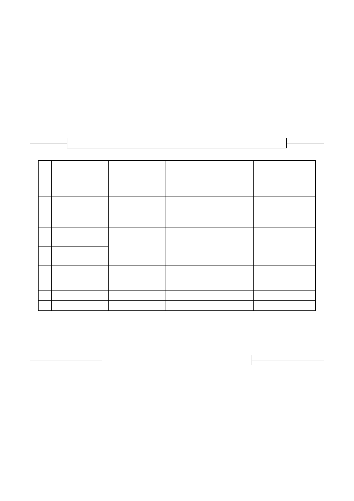
7-2. Control Specifications
No.
1
When power
supply is reset
2
Operation mode
selection
Item
Outline of specifications
1) Distinction of outdoor units
When the power supply is reset, the outdoors are
distinguished, and control is exchanged according to
the distinguished result.
2) Setting of speed of the indoor fan/setting whether to
adjust air direction or not.
Based on EEPROM data, speed of the indoor fan or
setting whether to adjust air direction or not is selected.
1) Based on the operation mode selecting command
from the remote controller, the operation mode is
selected.
Remote controller
command
STOP
FAN
COOL
DRY
HEAT
AUTO
Ta
(˚C)
+1.5
Tsc
or Tsh
-1.5
COOL
Outline of control
Air conditioner stops.
Fan operation
Cooling operation
Dry operation
Heating operation
• COOL/HEAT operation mode
is automatically selected by Ta
and Ts for operation.
(COOL ON)
(COOL OFF)
HEAT
Remarks
Air speed/
Air direction adjustment
Ta : Room temperature
Ts : Setup temperature
Tsc : Setup temperature in
cooling operation
Tsh: Setup temperature
+ Room temperature
control temperature
compensation
1) Judge the selection of COOL/HEAT mode as shown
in the figure above.
When 10 minutes passed after thermostat had
been turned off, the heating operation (Thermo
OFF) is exchanged to cooling operation if Tsh
exceeds +1.5 or more.
(COOL OFF) and (COOL ON) in the figure indicate
an example.
When 10 minutes passed after thermostat had
been turned off, the cooling operation (Thermo
OFF) is exchanged to heating operation if Tsc
exceeds –1.5 or less.
2) For the automatic capacity control after judgment of
COOL/HEAT, refer to item 4.
3) For the temperature correction of room temperature
control in automatic heating operation, refer to item 3.
– 39 –
Page 40

No.
3
Item
Room
temperature
control
Outline of specifications
1) Adjustment range Remote controller setup temperature (°C)
Wired type
Wireless type
COOL/
DRY
18 to 29
18 to 30
Heating
operation
18 to 29
16 to 30
Auto
operation
18 to 29
17 to 27
Remarks
Automatic
4
capacity control
(GA control)
5
selection
2) Using the item code 06, the setup temperature in
heating operation can be compensated.
Setup data
Setup temp.
compensation
0246
+0°C+2°C+4°C+6°C
Setting at shipment
Setup data 2
1) Based on the difference between Ta and Ts, the
operation frequency is instructed to the outdoor unit.
1) Operation with (HH), (H), (L), or [AUTO] mode is
performed by the command from the remote controller .
2) When the air speed mode [AUTO] is selected, the air
speed varies by the difference betw een Ta and Ts.
<COOL>
Ta (˚C)
+3.0
+2.5
+2.0
+1.5
+1.0
+0.5
Tsc
-0.5
HH
(HH)
H (HH)
H (HH)
L(H)
L(H)
L(H)
L(L)
A
B
C
D
E
F
G
Shift of suction temperature in heating operation
HH > H > L > LLAir speed
• Controlling operation in case when thermo of remote
controller works is same as a case when thermo of
the body works.
• If the air speed has been changed once, it is not
changed for 3 minutes. However when the air volume
is exchanged, the air speed changes.
• When cooling operation has started, the air speed
selects a downward slope, that is, the high position.
• If the temperature is just on the difference boundary,
the air speed does not change.
• Mode in the parentheses indicates one in automatic
cooling operation.
– 40 –
Page 41

No.
5
Item
Air speed
selection
(Continued)
Outline of specifications
<HEAT>
Ta (˚C)
L(L)
(-0.5)
(0)
(+0.5)
–1.0
Tsh
+1.0
L(H)
H(H)
H
E
D
(HH)
(+1.0)
(+1.5)
(+2.0)
+2.0
+3.0
+4.0
HH
(HH)
C
B
A
Value in the parentheses indicates one when thermostat of
the remote controller works.
Value without parentheses indicates one when thermostat of
the body works.
• If the air speed has been changed once, it is not changed
for 1 minute. However when the air speed is exchanged, the
air speed changes.
• When heating operation has started, the air speed selects a
upward slope, that is, the high position.
• If the temperature is just on the difference boundary, the air
speed does not change.
• Mode in the parentheses indicates one in automatic heating
operation.
• In Tc ≥ 60°C, the air speed increases by 1 step.
Remarks
<Operation of duct only>
Standard
COOL HEAT
UL UL
L
L+ L
L+
M
M
M+ M+
H
H
High ceiling
COOL HEAT
UL UL
LL
L+ L+
M+,M M+,M
HH
Tap
FD
FD
FB
FA
F9
F8
F7
F6
F5
F4
F3
F2
F1
SM562
Revolutions per
minute (rpm)
360 360
610 550
610 550
670 590
730 640
730 640
790 690
850 750
850 750
870 790
880 830
880 830
900 900
SM402
SM452
Tc: Indoor heat exchanger sensor temperature
3) In heating operation, the mode changes to [UL] if thermo-
stat is turned off.
4) If Ta ≥ 25°C when heating operation has started and when
defrost operation has been cleared, it operates with HIGH
(H) mode or (HH) for 1 minute from when Tc has entered
in E zone of cool air discharge preventive control (Item 6).
5) In automatic cooling/heating operation, the revolution
frequency of [HH] is set larger than that in the standard
cooling/heating operation. However the revolution frequency is restricted in the automatic heating operation as
shown in the following figure.
[PRE-HEAT] display
Tc
(˚C)
47
42
F5 ® F4
F5
– 41 –
Page 42

No.
6
Item
Cool air
discharge
preventive
control
Outline of specifications
1) In heating operation, the indoor fan is controlled based
on the detected temperature of Tc sensor or Tcj sensor.
As shown below, the
upper limit of the
revolution frequency
is determined.
Tc
Tcj
(˚C)
32
30
28
26
20
16
HH
UL
OFF
H
L
E zone
D zone
C zone
B zone
A zone
Remarks
In D or E zone, the priority
is given to setup of air
volume exchange .
In A and B zones,
[PRE-HEAT] is displayed.
78Freeze
preventive
control
(Low
temperature
release)
1) The cooling operation (including Dry operation) is
performed as follows based on the detected temperature of Tc sensor or Tcj sensor.
When [J] zone is detected for 6 minutes (Following
figure), the commanded frequency is decreased from
the real operation frequency. After then the commanded
frequency changes every 30 seconds while operation is
performed in [J] zone.
In [K] zone, time counting is interrupted and the operation is held.
When [I] zone is detected, the timer is cleared and the
operation returns to the normal operation.
If the commanded frequency becomes S0 because the
operation continues in [J] zone, the return temperature
A is raised from 5°C to 12°C until [I] zone is detected
and the indoor fan
operates with [M] mode.
(˚C)
5
I
2
J
In heating operation, the freeze-preventive control
works if 4-way v alve is not exchanged and the condition
is satisfied. (However the temperature for J zone
dashing control is changed from 2°C to –5°C.)
Tcj : Indoor heat ex-
changer sensor
temperature
A
K
High-temp
release control
1) The heating oper ation is performed as follows based on
the detected temperature of Tc sensor or Tcj sensor.
• When [M] zone is detected, the commanded fre-
quency is decreased from the real operation frequency. After then the commanded frequency
changes ev ery 30 seconds while operation is performed in [M] zone.
• In [N] zone, the commanded frequency is held.
• When [L] zone is detected, the commanded fre-
quency is returned to the original value by approx.
6Hz every 60 seconds.
Setup at
shipment
Control temp (°C)
AB
56 (54) 52 (52)
Tcj
(˚C)Tc
A
B
L
M
N
NOTE :
When the operation has started or when Tc or Tcj became
lower than 30°C after start of the operation, temperature is
controlled between values in parentheses of A and B.
– 42 –
Same when thermostat is
turned off.
Page 43

No.
9
Drain pump control
Item
Outline of specifications
1) In cooling operation (including Dry operation), the
drain pump is usually operated.
2) If the float switch operates while drain pump
operates, the compressor stops, the drain pump
continues the operation, and a check code is
output.
3) If the float switch operates while drain pump stops,
the compressor stops and the drain pump operates. If the float switch keeps operating for approx.
4 minutes, a check code is output.
Remarks
Check code [P10]
1011After-heat
elimination
Flap control
When heating operation stops, the indoor fan operates
with LOW mode f or approx. 30 seconds.
1) Flap position setup
• When the flap position is changed, the position
moves necessarily to downward discharge
position once to return to the set position.
• The flap position can be set up in the following
operation range.
In cooling/dry operation
In heating/fan operation
• In group twin/triple operation, the flap positions
can be set up collectively or individually.
2) Swing setup
• The swinging position can be moved in the
following operation range .
All modes
• In group twin/triple operation, the swinging
positions can be set up collectively or individually.
3) When the unit stops or when a warning is output,
the flap automatically moves downw ard.
4) While the heating operation is ready, the flap
automatically moves upward.
– 43 –
Warning :
A check code is displa yed
on the remote controller,
and the indoor unit stops.
(Excluding [F08] and
[L31])
Page 44

No.
12
Frequency fixed
operation
(Test run)
Item
Outline of specifications
<In case of wired remote controller>
1. When pushing [CHECK] button for 4 seconds or more,
[TEST] is displayed on the display screen and the
mode enters in Test run mode.
2. Push [ON/OFF] button.
3. Using [MODE] button, change the mode from [COOL]
to [HEAT].
• Do not use other mode than [COOL]/[HEAT] mode.
• During test run operation, the temperature cannot be
adjusted.
• An error is detected as usual.
• A frequency fixed operation is performed.
4. After the test run, push [ON/OFF] button to stop the
operation. (Display in the display part is same as the
procedure in item 1).)
5. Push [CHECK] b utton to clear the test run mode.
([TEST] display in the display part disappears and the
status returns to the normal stop status.)
<In case of wireless remote controller>
1. Turn off the power of the set.
Remove the adjuster with sensors from the ceiling
panel.
2. Turn Bit [1: TEST] of sensor P.C. board switch [S003]
from OFF to ON.
Attach the sensor P.C. board cover and mount the
adjuster with sensors to the ceiling panel.
Turn on the power of the set.
3. Push [ON/OFF] button of the wireless remote controller
and set the operation mode to [COOL] or [HEAT] using
[MODE] button.
(During test run operation, all the display lamps of
wireless remote controller sensors flash.)
• Do not use other mode than [COOL]/[HEAT] mode.
• An error is detected as usual.
• A frequency fixed operation is performed.
4. After the test run, push [ON/OFF] button to stop the
operation.
5. Turn off the power of the set.
Turn Bit [1: TEST] of sensor P.C. board switch [S003]
from ON to OFF.
Mount the adjuster with sensors to the ceiling panel.
Remarks
13 Filter sign display
(Except wireless
type)
1) The operation time of the indoor fan is calculated, the
filter reset signal is sent to the remote controller when
the specified time (2500H) has passed, and it is
displayed on LCD.
2) When the filter reset signal has been received from the
remote controller, time of the calculation timer is
cleared. In this case, the measurement time is reset if
the specified time has passed, and display on LCD
disappears.
– 44 –
[FILTER] goes on.
Page 45

No.
14
Central control
mode selection
15
Energy-save
control
(By connected
outdoor unit)
Item
Outline of specifications
1) Setting at the central controller side enables to select
the contents which can be operated on the remote
controller at indoor unit side.
2) RBC-AMT31E, RBC-AMT32E
[Last push priority] :
The operation contents can be selected from both
remote controller and central controller of the indoor
unit side, and the operation is performed with the
contents selected at the last.
[Center] :
Start/Stop operation only can be handled on the
remote controller at indoor unit side.
[Operation Prohibited] :
It cannot be operated on the remote controller at
indoor unit side. (Stop status is held.)
1) Selecting [AUTO] mode enables an energy-saving to
be operated.
2) The setup temperature is shifted (corrected) in the
range not to lose the comfort ability according to input
values of various sensors.
3) Data (Input value room temp. Ta, Outside temp. To, Air
volume, Indoor heat exchanger sensor temp. Tc) for
20 minutes are taken the average to calculate
correction value of the setup temperature.
4) The setup temperature is shifted every 20 minutes,
and the shifted range is as follows.
In cooling time : +1.5 to –1.0K
In heating time : –1.5 to +1.0K
Remarks
(No display)
[
] goes on.
[
] goes on.
In a case of wireless type, the
display lamp does not change.
However, contents which can be
operated are same.
The status set in [ ] /
[Operation Prohibited] mode is
notified with the receiving sound
“Pi, Pi, Pi, Pi, Pi” (5 times).
16
Max. frequency
cut control
17
DC motor
1) This control is operated by selecting [AUTO] operation mode.
2) COOL operation mode: the frequency
is controlled according to the following
Ta(˚C)
+4
Normal control
figure if To < 28°C.
+3
Tsc
3) HEAT operation mode: the frequency
is controlled according to the right
Ta(˚C)
Tsh
figure if To > 15°C.
–3
–4
Normal control
1) When the fan operation has started, positioning of the
stator and the rotor are performed.
(Moves slightly with tap sound)
2) The motor operates according to the command from
the indoor controller.
NOTES :
• When the fan rotates while the air conditioner stops
due to entering of outside air, etc, the air conditioner
may operated while the fan motor stops.
• When a fan locking is found, the air conditioner stops,
and an error is displayed.
Max. frequency is restricted
to approximately the rated
cooling frequency
Max. frequency is restricted
to approximately the rated
heating frequency
Check code [P12]
– 45 –
Page 46

7-3. Indoor Print Circuit Board
7-3-1. Compact 4-way Cassette Type
<MCC-1402>
Microcomputer operation LED
DC fan output
Filter/Option error input EEPROM Connection interface
Indoor/Outdoor
inter-unit cable
Optional
power supply
– 46 –
Remote controller
power supply LED
DC fan return
*1
Drain pump output
Float SW
Fan output
HA (T10)
TA sensor Remote controller inter-unit cable
Optional output TC sensor
Louver
(Used only for 4-way Air Discharge Cassette Type, Under Ceiling type)
DISP
CHK
TCJ sensor
EXCT
Used for
servicing
Page 47

8. CIRCUIT CONFIGURATION AND CONTROL SPECIFICATIONS
8-1. Indoor Control Circuit
8-1-1. Outline of Main Controls
1. Pulse Motor Valve (P.M.V.) control
1) PMV is controlled with 50 to 500 pulses during operation, respectively.
2) In cooling operation, PMV is controlled with the temperature difference between TS sensor and TC sensor.
3) In heating operation, PMV is controlled with the temperature difference between TS sensor and TE sensor.
4) For the temperature difference in items 2) and 3), 1 to 5K is aimed as the target in both cooling and heating
operations.
5) When the cycle excessively rose in both cooling and heating operations, PMV is controlled by TD sensor.
The aimed value is usually 106°C for SP404, SP454, SM562, SM563, 100°C for SP562 in both cooling and
heating operations.
CAUTION
A sensor trouble may cause a liquid back-flow or abnormal overheat resulting in excessive shortening of the
compressor life. In a case of trouble on the compressor, be sure to check there is no error in the resistance
value an the refrigerating cycle of each sensor after repair and then start the operation.
2. Discharge temperature release control
1) This function controls the operation frequency,
that is, lowers the operation frequency when the
discharge temperature has not lower or the
discharge temperature has rapidly risen during
P.M.V. control.
It subdivides the frequency control up to a unit
of 0.6Hz to stabilize the cycle.
2) When the discharge temperature is detected in
an abnormal stop zone, the unit stops the
compressor and restarts after 2 minutes 30
seconds.
The error counter is cleared when it has
continued the operation for 10 minutes.
If the abnormal stop zone has been detected by
8 times without clearing of counter, an error
“P03” is displayed.
∗ The cause is considered as excessively little
amount of refrigerant, defective PMV, or
clogging of cycle.
abcde
SM562, SM563,
SP404, SP454
SP562
117 107 103 100 93
111 106 100 95 90
[°C]
I1
1–0.5
TD [˚C]
Error stop ("P03" display with 8 times of error counts)
a
Frequency down
b
c
Frequency holding
d
Frequency slow-up
(Up to command)
e
As command is
[A]
Frequency down
Hold
Hold
Normal operation
3. Current release control
The output frequency and the output voltage are controlled by AC current value detected by T02 on the
outdoor P.C. board so that input current of the inverter does not exceed the specified value.
Objective
model
SM562, SM563
SP404, SP454
SP562
11 value [A]
COOL HEAT
10.13 12.00
10.13 10.50
11.55 13.43
* For the cooling only models, only COOL is objective.
– 47 –
Page 48

8-1-2. Indoor P.C. Board Optional Connector Specifications
Function
Option output
Outside error
input
Filter option
error
CHK
Operation check
DISP display
mode
EXCT demand
Connector
No.
CN60
CN80
CN70
CN71
CN72
CN73
Pin
No.
1
2
3
4
5
6
1
2
3
1
2
1
2
1
2
1
Specifications
DC12V (COM)
Defrost output
Thermo. ON output
Cooling output
Heating output
Fan output
DC12V (COM)
DC12V (COM)
Outside error input
Filter/Option/Humidifier
setup input
0V
Check mode input
0V
Display mode input
0V
Demand input
Remarks
ON during defrost operation of outdoor unit
ON during Real thermo-ON (Comp ON)
ON when operation mode is in cooling system
(COOL, DRY, COOL in AUTO cooling/heating)
ON when operation mode is in heating system
(HEAT, HEAT in AUTO cooling/heating)
ON during indoor fan ON
(Air purifier is used/Interlock cable)
(When continued for 1 minute)
Check code “L30” is output and forced operation stops.
Option error input is controlled. (Protective operation
for device attached to outside is displayed.)
* Setting of option error input is performed from
remote controller. (DN=2A)
Used for operation check of indoor unit.
(Communication with outdoor unit or remote controller
is not performed, but the specified operation such as
indoor fan “H” or drain pump ON is output.)
Display mode enables indoor unit and remote controller to communicate. (When power is turned on)
2
0V
Forced thermo-OFF operation in indoor unit
– 48 –
Page 49

9. TROUBLESHOOTING
9-1. Summary of Troubleshooting
<Wired remote controller type>
1. Before troubleshooting
1) Required tools/instruments
•+ and – screwdrivers, spanners, radio cutting pliers, nippers, push pins for reset switch
• Tester, thermometer, pressure gauge, etc.
2) Confirmation points before check
a) The following operations are normal.
1. Compressor does not operate.
• Is not 3-minutes delay (3 minutes after compressor OFF)?
• Does not thermostat turn off?
• Does not timer operate during fan operation?
• Is not outside high-temperature operation controlled in heating operation?
2. Indoor fan does not rotate.
• Does not cool air discharge prev entive control work in heating operation?
3.Outdoor fan does not rotate or air volume changes.
• Does not high-temperature release operation control work in heating operation?
• Does not outside low-temperature operation control work in cooling operation?
• Is not defrost operation performed?
4. ON/OFF operation cannot be performed from remote controller.
• Is not the control operation performed from outside/remote side?
• Is not automatic address being set up?
(When the power is turned on at the first time or when indoor unit address setting is changed, the
operation cannot be performed for maximum approx. 5 minutes after power-ON.)
b) Did you return the cabling to the initial positions?
c) Are connecting cables of indoor unit and remote controller correct?
2. Troubleshooting procedure
When a trouble occurred, check the parts along with the following procedure .
Trouble Confirmation of check code display Check defective position and parts.
→→
NOTE :
For cause of a trouble, power conditions or malfunction/erroneous diagnosis of microcomputer due to outer
noise is considered except the items to be checked. If there is any noise source, change the cables of the
remote controller to shield cables.
– 49 –
Page 50

<Wireless remote controller type>
1. Before troubleshooting
1) Required tools/instruments
•+ and – screwdrivers, spanners, radio cutting pliers, nippers, etc.
• Tester, thermometer, pressure gauge, etc.
2) Confirmation points before check
a) The following operations are normal.
1. Compressor does not operate.
• Is not 3-minutes delay (3 minutes after compressor OFF)?
• Does not thermostat turn off?
• Does not timer operate during fan operation?
• Is not outside high-temperature operation controlled in heating operation?
2. Indoor fan does not rotate.
• Does not cool air discharge prev entive control work in heating operation?
3) Outdoor fan does not rotate or air volume changes.
• Does not high-temperature release operation control work in heating operation?
• Does not outside low-temperature operation control work in cooling operation?
• Is not defrost operation performed?
4) ON/OFF operation cannot be performed from remote controller.
• Is not forced operation perf ormed?
• Is not the control operation performed from outside/remote side?
• Is not automatic address being set up?
a) Did you return the cabling to the initial positions?
b) Are connecting cables between indoor unit and receiving unit correct?
2. Troubleshooting procedure
(When the power is turned on at the first time or when indoor unit address setting is changed, the operation
cannot be performed for maximum approx. 5 minutes after power-ON.)
When a trouble occurred, check the parts along with the following procedure .
Confirmation of lamp display
Trouble
1) Outline of judgment
The primary judgment to check where a trouble occurred in indoor unit or outdoor unit is performed with
the following method.
→→
(When 4-way air discharge cassette type
wireless remote controller is connected)
Check defective
position and parts.
Method to judge the erroneous position by flashing indication on the display part of indoor unit
(sensors of the receiving unit)
The indoor unit monitors operating status of the air conditioner , and the blocked contents of self-diagnosis
are displayed restricted to the following cases if a protective circuit works.
– 50 –
Page 51

– 51 –
9-2. Check Code List
Wireless sensor
lamp display
Operation
¥
Timer Ready
ll
ll
¥
ll
¥
ll
¥
ll
¥¥
¥¥
¥¥¡
¥¥¡
¥¥¡
¥¥
¥¥
¥
ll
¥
l
¥
l
¥
l
¥
l
¥
l
¥
l
l
l
l
l
l
¥
¥
¥
Wired remote
controller
Check code
E03
E04
E08
E10
E18
F01
F02
F04
F06
F08
F10
F29
H01
H02
H03
L03
L07
L08
Error mode detected by indoor and outdoor units
Diagnostic function
Cause of operation
No communication from remote controller (including wireless) and
communication adapters
The serial signal is not output from outdoor unit to indoor unit.
• Miscabling of inter-unit cables
• Defective serial sensing circuit on outdoor P.C. board
• Defective serial receiving circuit on indoor P.C. board
Duplicated indoor unit addresses
Communication error between indoor MCU
• Communication error between fan driving MCU and main MCU
Regular communication error between master and sub indoor units or
between main and sub indoor units
Coming-off, disconnection or short of indoor heat exchanger sensor (TCJ)
Coming-off, disconnection or short of indoor heat exchanger sensor (TC)
Coming-off, disconnection or short of outdoor temperature sensor (TD)
Coming-off, disconnection or short of outdoor temperature sensor (TE/TS)
Coming-off, disconnection or short of outdoor temperature sensor (TO)
Coming-off, disconnection or short of indoor heat exchanger sensor (TA)
Indoor EEPROM error
• EEPROM access error
Breakdown of compressor
• Displayed when error is detected
Compressor does not rotate.
• Over-current protective circuit operates after specified time passed
when compressor had been activated.
Current detection circuit error
• Current value at AC side is high even during compressor-OFF.
• Phase of power supply is missed.
Duplicated indoor master units
There is group line in individual indoor units.
Unsetting of indoor group address
Status of
air conditioner
Stop
(Automatic reset)
S top
(Automatic reset)
Stop
Stop
(Automatic reset)
Stop
(Automatic reset)
Stop
(Automatic reset)
Stop
(Automatic reset)
Stop
Stop
Operation
continues.
Stop
(Automatic reset)
Stop
(Automatic reset)
Stop
Stop
Stop
Stop
Stop
Stop
Condition
Displayed when
error is detected
Displayed when
error is detected
Displayed when
error is detected
Displayed when
error is detected
Displayed when
error is detected
Displayed when
error is detected
Displayed when
error is detected
Displayed when
error is detected
Displayed when
error is detected
Displayed when
error is detected
Displayed when
error is detected
Displayed when
error is detected
Displayed when
error is detected
Displayed when
error is detected
Displayed when
error is detected
Displayed when
error is detected
Displayed when
error is detected
Displayed when
error is detected
: Flash, ¡ : Go on, l : Go off
¥
Judgment and measures
1. Check cables of remote controller and communication adapters.
• Handy remote controller LCD display OFF (Disconnection)
• Central remote controller [97] check code
1. Outdoor unit does not completely operate.
• Inter-unit cable check, correction of miscabling, case thermo operation
• Outdoor P.C. board chec k, P.C. board cables check
2. In normal operation
P.C. board (Indoor receiving/Outdoor sending) check
1. Check whether there is modification of remote controller connection (Group/Individual)
or not after power has been turned on (finish of group configuration/address check).
* If group configuration and address are not normal when the power has been turned
on, the mode automatically shifts to address setup mode. (Resetting of address)
1. Check cables of remote controller.
2. Check power cables of indoor unit.
3. Check indoor P.C. board.
1. Check cables of remote controller.
2. Check indoor power cable.
3. Check indoor P.C. board.
1. Check indoor heat exchanger temperature sensor (TCJ).
2. Check indoor P.C. board.
1. Check indoor heat exchanger temperature sensor (TC).
2. Check indoor P.C. board.
1. Check outdoor temperature sensor (TD).
2. Check outdoor CDB P.C. board.
1. Check outdoor temperature sensor (TE/TS).
2. Check outdoor CDB P.C. board.
1. Check outdoor temperature sensor (TO).
2. Check outdoor CDB P.C. board.
1. Check indoor heat exchanger temperature sensor (TA).
2. Check indoor P.C. board.
1. Check indoor EEPROM. (including socket insertion)
2. Check indoor P.C. board.
1. Check power voltage. A C200V ±20V
2. Overload operation of refrigerating cycle
3. Check current detection circuit at AC side.
1. Trouble of compressor (Compressor lock, etc.) : Replace compressor.
2. Defective cabling of compressor (Phase missing)
3. Phase-missing operation of power supply (3-phase model)
1. Compressor immediately stops even if restarted. : Check IPDU .
2. Phase-missing operation of power supply
Check 3-phase power voltage and cables .
1. Check whether there is modification of remote controller connection (Group/Individual)
or not after power has been turned on (finish of group configuration/address check).
* If group configuration and address are not normal when the power has been turned
on, the mode automatically shifts to address setup mode. (Resetting of address)
Page 52

: Flash, ¡ : Go on, l : Go off
¥
Wireless sensor
lamp display
Operation
¥
l
Timer Ready
l
¥
¥¡¥
¥¡¥
No check code is displayed.
¥
l
¥
l
¥¥
– 52 –
l
l
¥
¥
¥
¥
¥
¥¥
l
l
l
l
l
¥
l
¥
¥
¥
¥
¥
¥
¥
Wired remote
controller
Check code
L09
L29
L30
L31
P03
P04
P10
P12
P19
P22
P26
P29
P31
Diagnostic function
Cause of operation
Unset indoor capacity
Outdoor unit and other errors
• Communication error between CDB and IPDU (Coming-off of connector)
• Heat sink temperature error (Detection of temperature over specified value)
Abnormal outside interlock input
Phase detection protective circuit operates. (Normal models)
Fan motor thermal protection
Discharge temperature error
• Discharge temperature over specified value was detected.
High-pressure protection error by TE sensor
(Temperature over specified value was detected.)
Float switch operation
• Disconnection, coming-off, defective float switch contactor of float circuit
Indoor DC fan error
Error in 4-way valve system
• Indoor heat exchanger temperature lowered after start of heating operation.
Outdoor DC fan error
Inverter over-current protective circuit operates. (For a short time)
Short voltage of main circuit operates.
IPDU position detection circuit error
Own unit stops while warning is output to other indoor units.
Status of
air conditioner
Stop
Stop
Stop
Operation continues.
(Compressor stops.)
Stop
Stop
Stop
Stop
Stop
Stop
(Automatic reset)
Stop
Stop
Stop
Stop (Sub unit)
(Automatic reset)
Condition
Displayed when
error is detected
Displayed when
error is detected
Displayed when
error is detected
Displayed when
error is detected
Displayed when
error is detected
Displayed when
error is detected
Displayed when
error is detected
Displayed when
error is detected
Displayed when
error is detected
Displayed when
error is detected
Displayed when
error is detected
Displayed when
error is detected
Displayed when
error is detected
Displayed when
error is detected
Judgment and measures
1. Set the indoor capacity. (DN=I1)
1. Check cables of CDB and IPDU.
2. Abnormal overload operation of refrigerating cycle
1. Check outside devices.
2. Check indoor P.C. board.
1. Check power phase order (Reversed phase)/phase missing.
2. Check outdoor P.C. board.
1. Check thermal relay of fan motor.
2. Check indoor P.C. board.
1. Check refrigerating cycle. (Gas leak)
2. Trouble of PMV
3. Check Td sensor.
1. Overload operation of refrigerating cycle
2. Check outdoor temperature sensor (TE).
3. Check outdoor CDB P.C. board.
1. Defect of drain pump
2. Clogging of drain pump
3. Check float switch.
4. Check indoor P.C. board.
1. Defective detection of position
2. Over-current protective circuit of indoor fan driving unit operates.
3. Lock of indoor fan
4. Check indoor P.C. board.
1. Check 4-way valve.
2. Check indoor heat exchanger (TC/TCJ) sensor.
3. Check indoor P.C. board.
1. Defective detection of position
2. Over-current protective circuit of outdoor fan driving unit operates.
3. Lock of outdoor fan
4. Check outdoor CDB P.C. board.
1. Inverter immediately stops even if restarted. : Compressor motor rare short
2. Check IPDU. : Cabling error
1. Position detection circuit operates even if operating compressor by removing
3P connector. : Replace IPDU.
1. Judge sub unit while master unit is in [E03], [L03], [L07], [L08].
2. Check indoor P.C. board.
For an error mode detected in outdoor unit, the fan operates because sub unit of a group operation does not communicate with the outdoor unit.
Page 53

Error mode detected by remote controller
: Flash, ¡ : Go on, l : Go off
¥
Wireless sensor
lamp display
Operation
Timer Ready
———
¥ll
¥ll
¥ll
– 53 –
¥¡¥
Wired remote
controller
Check code
No check code
is displayed.
(Remote controller
does not operate.)
E01
E02
E09
L20
Diagnostic function
Cause of operation
No communication with master indoor unit
• Remote controller cable is not correctly connected.
• Power of indoor unit is not turned on.
• Automatic address cannot be completed.
No communication with indoor master unit
• Disconnection of inter-unit cable between remote
controller and master indoor unit
(Detected at remote controller side)
Signal sending error to indoor unit
(Detected at remote controller side)
Multiple master remote controllers are recognized.
(Detected at remote controller side)
Duplicated indoor central addresses on communication
of central control system
(Detected by central controller side)
Status of
air conditioner
Stop
Stop
* When there is center, operation continues.
* When there is center , operation continues.
(Automatic restart)
Stop
(Automatic restart)
(Sub unit continues operation.)
Stop
Stop
(Automatic restart)
Condition
—
Displayed when
error is detected
Displayed when
error is detected
Displayed when
error is detected
Displayed when
error is detected
Judgment and measures
Remote controller power error, Defective indoor EEPROM
1. Check remote controller inter-unit cables.
2. Check remote controller.
3. Check indoor power cables.
4. Check indoor P.C. board.
5. Check indoor EEPROM. (including socket insertion)
: Phenomenon of automatic address repetition occurred.
Signal receiving of remote controller is defective.
1. Check remote controller inter-unit cables.
2. Check remote controller.
3. Check indoor power cables.
4. Check indoor P.C. board.
Signal sending of remote controller is defective.
1. Check sending circuit inside of remote controller.
: Replace remote controller.
1. Check there are multiple master units for 2 remote controllers
(including wireless).
: Master unit is one and others are sub units.
1. Check address setup of central control system network. (DN = 03)
Wireless sensor
lamp display
Operation
Timer Ready
———
———
———
Wired remote
controller
Check code
C05
C06
P30
Error mode detected by central remote controller
Cause of operation
Sending error central remote controller
Receiving error in central remote controller
Differs according to error contents of unit with
occurrence of alarm.
Diagnostic function
Status of
air conditioner
Operation continues
Operation continues
Continuation/Stop
(Based on a case)
Condition
Displayed when
error is detected
Displayed when
error is detected
Displayed when
error is detected
: Flash, ¡ : Go on, l : Go off
¥
Judgment and measures
1. Check communication line/miscabling/ Check power of indoor unit.
2. Check communication. (U3, U4 terminals)
3. Check network adapter P.C. board.
4. Check central controller (such as central control remote controller, etc.).
5. Terminal resistance check (connection interface SW01)
Check the check code of corresponding unit by remote controller
Page 54

9-3. Error Mode Detected by LED on Outdoor P.C. Board
RAV-SP562A T-E only
<SW801: LED display in bit 1, bit 2 OFF>
• When multiple errors are detected, the latest error is displayed.
• When LED display is ¡ (Go on), there is the main cause of trouble on the objective part of control at CDB
side and the unit stops.
• When LED display is ¥ (Flash), there is the main cause of trouble on the objective part of control at IPDU
side and the unit stops.
• When case thermostat operates, the communication is interrupted on the serial circuit.
If continuing the case thermostat operation, a serial communication error occurs because serial sending to
the indoor unit is interrupted.
CDB side
IPDU side
No.
1
TE sensor error
2
TD sensor error
3
TS sensor error
4
TO sensor error
5
Discharge temp. error
6
DC outdoor fan error
7
Communication error between IPDU
(Abnormal stop)
8
High-pressure release operation
9
EEPROM error
10
Communication error between IPDU
(No abnormal stop)
11
IGBT short-circuit protection
12
Detection circuit error
13
Current sensor error
14
Comp. lock error
15
Comp. breakdown
Item
Check
code
Type A
F06
F04
F06
F08
P03
P22
L29
P04
—
—
P26
P29
H03
H02
H01
LED display
D800 D801 D802 D803
(Red) (Yellow) (Yellow) (Yellow)
¡
¡¡
ll
l
l
¡¡¡
¡
l
¡¡
ll
¥
l
¥¥
ll
¥
lll
ll
¡
¡
ll
¡¡
l
l
l
ll
¡
l
l
¡¡
¡
¡
¡
lll
¥
ll
ll
l
¥
¥
l
l
: Go on l : Go off ¥ : Flash (5Hz)
¡
<<Check code>>
The check codes are classified into Type A and Type B according to the used remote controller.
Be sure to check the remote controller which you use .
Type A :
Neutral 2-cores type wired remote controller such as RBC-AMT31E, RBC-AMT32E, RBC-AS21E2,
and wireless remote controller kit such as TCB-AX21E2
– 54 –
Page 55

9-4. Troubleshooting Procedure for Each Check Code
9-4-1. Check Code
[E01 error]
Is inter-unit cable of A and B normal?
YES
Is there no disconnection
or contact error of connector on harness
from terminal block of indoor unit?
NO
NO
Is group control operation?
YES
Is power of all indoor units turned on?
YES
Is power supplied to remote controller?
AB terminal: Approx. DC18V
YES
Are two remote controllers
set without master unit?
NO
NO
YES
NO
NO
YES
Correct inter-unit cable of remote controller.
Correct connection of connector.
Check circuit cables.
Check power connection of indoor unit.
(Turn on power again.)
Check indoor P.C. board (MCC-1402).
Defect → Replace
Correct as a master unit/a sub unit
(Remote controller address connector)
[E09 error]
Are two remote controllers
set without master unit?
NO
YES
Check remote controller P.C. board.
Defect → Replace
Correct as a master unit/a sub unit
(Remote controller address connector)
Check remote controller P.C. board.
Defect → Replace
– 55 –
Page 56

[E04 error]
Does outdoor unit operate?
YES
NO
Is setup of group address correct?
YES
Are 1, 2, 3 inter-unit cables normal?
YES
Are connections from connectors
of inter-terminal blocks (1, 2, 3)
of indoor/outdoor units normal?
YES
2 and 3 of inter-terminal blocks (1, 2, 3)
Does voltage between
of indoor unit vary?*
YES
As shown in the following figure, perform measurement
*
within 20 seconds after power ON.
NO
NO
NO
NO
Check item code [14].
Correct inter-unit cable.
Correct connection of connector.
Check indoor P.C. board
(MCC-1402).
Defect → Replace
Check indoor P.C. board (MCC-1402).
Defect → Replace
Check outdoor P.C. board
Defect → Replace
MCC-5009
MCC-1531 and MCC-1438
Does case thermo. operate?
NO
Black
3
White
Inter-terminal block
YES
RAV-SM562AT-E, RAV-SM563AT-E
RAV-SP404AT-E, RAV-SP454AT-E
RAV-SP562AT-E
2
1
S5277G
Check/Correct charged
refrigerant amount.
– 56 –
Page 57

[E10 error]
Check indoor control P.C. board (MCC-1402).
Defect → Replace
[E18 error]
Is inter-unit cable of A and B normal?
YES
Is there no disconnection
or contact error of connector on harness
from terminal block of indoor unit?
NO
Is group control operation?
NO
Check indoor P.C. board (MCC-1402).
Defect → Replace
NO
YES
YES
Is power of all indoor units turned on?
[E08, L03, L07, L08 error]
E08 : Duplicated indoor unit numbers
L03 : Two or more master units in a group control
L07 : One or more group addresses of [Individual] in a group control
L08 : Unset indoor group address (99)
Correct inter-unit cable of remote controller.
Correct connection of connector.
Check circuit cables.
NO
Check power connection of indoor unit.
(Turn on power again.)
If the above is detected when power has been turned on, the mode automatically enters in automatic address setup mode. (Check code is not displayed.)
Howe ver, if the above is detected during automatic address setup mode, the check code may be display ed.
[L09 error]
Is capacity of indoor unit unset?
YES
NO
Set capacity data of indoor unit.
(Setup item code (DN) = 11)
Check indoor P.C. board (MCC-1402).
Defect → Replace
– 57 –
Page 58

[L20 error]
Are cable connections to communication line U3, U4 normal?
YES
Are not multiple same central
control network addresses connected?
NO
Check central controller (including connection interface)
indoor P.C. board. Defect → Replace.
[L30 error]
Are outside devices of connector CN80 connected?
YES
Do outside devices normally operate?
YES
Check operation cause.
NO
YES
NO
NO
Correct cable connection
Correct central control network address.
Check indoor P.C. board (MCC-1402).
Defect → Replace
Check outside devices.
Defect → Replace
[P10 error]
Is connection of float switch connector
(Indoor control P.C. board CN34) normal?
YES
Does float
switch operate?
YES
Does drain pump
operate?
YES
Check drain pipe, etc.
[F10 error]
Is connection of TA sensor connector
(indoor P.C. board CN104) normal?
NO
Is circuit
cabling normal?
YES
Is power of drain
pump turned on?
YES
NO
Correct connection of connector.
NONO
NONO
Check and correct cabling/wiring.
Check indoor P.C. board (MCC-1402).
Defect → Replace
Check indoor P.C. board (MCC-1402).
Defect → Replace
Replace drain pump.
Check cabling.
Correct connection of connector.
YES
Are characteristics of TA sensor resistance value normal?
YES
* Refer to Characteristics-1.
– 58 –
NO
Replace T A sensor.
Check indoor P.C. board (MCC-1402).
Defect → Replace
Page 59

[P12 error]
<Only for 4-way air discharge cassette type models>
Turn off the power.
Are not there connections errors or
disconnection on connectors CN333 and CN334
of indoor unit P.C. board (MCC-1402)?
NO
Remove connectors CN333 and
CN334 of indoor unit P.C. board
(MCC-1402).
Does the fan rotate without trouble
when handling the fan with hands?
YES
Are resistance values between phases
at fan motor connector CN333 motor side of
indoor P.C. board (MCC-1402) correct? *1
YES
YES
Correct connection of connector.
NO
Replace indoor fan motor.
NO
Replace indoor fan motor.
1
*
• Are not coil windings between
between
5
(Black lead) and (Red lead) opened or shorted?
3 5
(White lead) and (Black lead), between
1
1 3
(Red lead) and (White lead),
→ For resistance, see the following values.
Approx. 70 to 100Ω
Is resistance value of fan motor connector
CN333 at motor side of indoor P.C. board
(MCC-1402) correct? *2
YES
Is signal output of indoor fan motor
position detection correct? *3
YES
Check indoor P.C. board
(MCC-1402).
Defect → Replace
NO
2
*
Check resistance of fan motor position detection circuit.
Is not coil winding between (Yellow lead) and (Pink lead)
1
Replace indoor fan motor.
4
opened or shorted? → Resistance: Approx. 5 to 20kΩ
NO
3
*
Check fan motor position detection signal.
• Using a tester, measure the voltage between CN334 and of
Replace indoor fan motor.
1 5
indoor P.C. board (MCC-1402) under condition that CN333 and
CN334 are mounted and the power is turned on.
→ Rotate the fan slowly with hands, and check the pin voltage
swings between 0 to 5V voltage.
• Between and : 5V
4 5
CN333
– 59 –
CN334
Page 60

[P22 error]
Are connections of CN301 and CN300
when handling the fan with hands under condition
of removing CN301 and CN300 from P.C. board?
The status that the resistance values
for 40Ω motor (ICF-140-40) and 25 to 55Ω
for 60Ω motor (ICF-140-60-1) is normal.
Between
Between
Between
of motor winding of connector (CN301)
5k to 20kW resistance values between
of P.C. board correct?
YES
Does the fan rotate without trouble
YES
between leads below are 50 to 80Ω
1
(Red lead) and 2 (White lead)
2
(White lead) and 3 (Black lead)
3
(Black lead) and 1 (Red lead)
YES
The status that there is
1
(Yellow lead) and 4 (Pink lead) of
motor position detection of
connector (CN300) is normal.
NO
NO
NO
CN301, ∗ CN303
CN300
CN300 : Motor coil winding
CN301 : Motor position detection
∗
CN301, CN303 : Motor coil winding
CN300, CN302 : Motor position detection
SP562AT-E
YES
Normal fan motor
(Control or CDB P.C. board)
(Control P.C. board or CDB P.C. board)
Defective fan motor
NOTE :
However, GND circuit error inside of the motor is rarely detected even if the above check is carried out.
When the circuit does not become normal even if P.C. board has been replaced, replace outdoor fan motor.
Single phase
Objective P.C. board
Fan motor winding
Motor position detection
RAV-SM562AT-E, SM563AT-E
RAV-SP404AT-E, SP454AT-E
Control P.C. board CDB P.C. board
CN300 CN301
CN301 CN300
RAV-SP562AT-E
– 60 –
Page 61

[P19 error]
NO
Check and replace
electron expansion valve.
NO
* Refer to
Characteristics-2.
Replace TC sensor.
Is operation of
4-way valve normal?
YES
Is flow of refrigerant
by electron expansion
valve normal?
YES
Are characteristics
of TC sensor resistance
value normal?
YES
NO
Is voltage applied
to 4-way valve coil terminal
in heating operation?
YES
Is circuit cable normal?
YES
Check CDB P.C. board.
YES
NO
Check 4-way valve
Defect → Replace
NO
Check and correct circuit.
NO
Check indoor P.C. board.
Defect → Replace
* For RAV-SM562AT-E, check control P.C. board.
Check CDB P.C. board.
Defect → Replace
• In cooling operation, if high pressure is abnormally raised, [P19 error]/[08 error] may be displayed. In this
case, remove cause of pressure up and then check again referring to the item [P04 error]/[21 error].
[F02 error]
Is connection of TC sensor connector
(Indoor P.C. board CN101) normal?
YES
Are characteristics of
TC sensor resistance value normal?
YES
NO
Correct connection of connector.
NO
Replace TC sensor.
* Refer to Characteristics-2.
Check indoor P.C. board
(MCC-1402).
Defect → Replace
– 61 –
Page 62

[F01 error]
Is connection of TCJ sensor connector
(Indoor P.C. board CN102) normal?
YES
Are characteristics of
TCJ sensor resistance value normal?
YES
Check indoor P.C. board
(MCC-1402).
Defect → Replace
[P26 error]
Is power voltage normal?
NO
Correct connection of connector.
NO
Replace TCJ sensor.
∗ Refer to Characteristics-2.
NO
Improve the power supply line.
Are connections of
cabling/connector normal?
YES
Does RY01 relay of
IPDU operate?
NO
YES
Is not AC fuse fused?
Replace IPDU.
∗ Replace control P.C. board of
RAV-SM562AT-E,
RAV-SM563AT-E,
RAV-SP404AT-E,
RAV-SP454AT-E.
YES
NO
∗ For RAV-SM562AT-E, RAV-SM563AT-E, RAV-SP404AT-E, RAV-SP454AT-E
check RY01 on the control P.C. board.
YES
∗ Single-phase type is not provided to
RAV-SM562AT-E, RAV-SM563AT-E
RAV-SP404AT-E, RAV-SP454AT-E.
NO
Are not “P26” and “14” errors output
when an operation is performed by
removing 3P connector of compressor?
Is compressor normal?
YES
Check and correct circuit cables.
Correct connection of connector.
Check and correct reactor connection.
NO
YES
Replace IPDU.
∗ Replace control P.C. board of
RAV-SM562AT-E, RAV-SM563AT-E
RAV-SP404AT-E, RAV-SP454AT-E.
NO
Check IPDU.
Defect → Replace
Check rare short of compressor trouble.
Defect → Replace
– 62 –
Page 63

[P29 error]
Are connections of
cable/connector normal?
YES
Is compressor normal?
YES
NO
NO
Is not earthed?
NO
Is not winding shorted?
(Is resistance between windings 0.6 to 1.2Ω?)
NO
Is not winding opened?
NO
Check IPDU P.C. board.
Defect → Replace
YES
YES
∗ For RAV-SM562AT-E, RAV-SM563AT-E,
RAV-SP404AT-E, RAV-SP454AT-E,
replace control P.C. board.
YES
Check and correct circuit cabling
such as cabling to compressor.
Compressor error → Replace
Compressor error → Replace
Compressor error → Replace
[H03 error]
Are cablings of power and
current sensor normal?
YES
Check IPDU.
Defect → Replace
NO
∗ For RAV-SM562AT-E, RAV-SM563AT-E, RAV-SP404AT-E, RAV-SP454AT-E
replace control P.C. board.
Check and correct circuit cables.
– 63 –
Page 64

[F06 error]
Are connections of
TE/TS sensor connectors of
CDB CN604/CN605 normal?
YES
Are characteristics of TE/TS sensor
resistance values normal?
YES
Check CDB.
Defect → Replace
[F04 error]
Is connection of TD sensor connector
of CDB CN600 normal?
NO
∗ (For RAV-SM562AT-E, RAV-SM563AT-E, RAV-SP404AT-E, RAV-SP454AT-E,
CN600 TE sensor and CN603 TS sensor)
NO
∗ Refer to Characteristics-3.
NO
Correct connection of connector.
Replace TE and TS sensors.
Correct connection of connector.
YES
Are characteristics of TD sensor
resistance value normal?
YES
Check control P.C. board.
Defect → Replace
[F08 error]
Is connection of TO sensor connector
of CDB CN601 normal?
YES
∗ (For RAV-SM562AT-E, RAV-SM563AT-E,
RAV-SP404AT-E, RAV-SP454AT-E, CN601 TD sensor)
NO
∗ Refer to Characteristics-4.
NO
∗ (For RAV-SM562AT-E, RAV-SM563AT-E,
RAV-SP404AT-E, RAV-SP454AT-E, CN602 TO sensor)
Replace TD sensor.
Correct connection of connector.
Are characteristics of TO sensor
resistance value normal?
YES
Check CDB.
Defect → Replace
NO
∗ Refer to Characteristics-5.
– 64 –
Replace TO sensor.
Page 65

[L29 error]
In the case of SUPER DIGITAL INVERTER
CDB CN800 and CDB IPDU CN06
Are connections of
connectors normal?
YES
Was the error just after
power ON determined?
NO
Is there no abnormal overload?
NO
Is IPDU P.C. board come to
closely contact with heat sink?
YES
Is power voltage normal?
NO
In the case of DIGITAL INVERTER
Is power voltage normal?
YES
Is compressor normal?
YES
NO
YES
YES
NO
YES
NO
NO
Are cabling/connector normal?
YES
NO
Correct connection of connector.
Check cabling between IPDU
and CDB and connector.
IPDU P.C. board error
Defect → Replace
Improve and eliminate the cause.
Correct mounting.
Check IPDU P.C. board.
Defect → Replace
Improve power line.
And power on once again.
Improve power line.
And power on once again.
Fault of compressor.
Check rare short
Defect → Replace
[H02 error]
Is power voltage normal?
YES
Are connections of
cable/connector normal?
YES
Is compressor normal?
YES
NO
NO
NO NO
Is there no
slackened refrigerant?
YES
Does electron expansion
valve normally operate?
YES
Check IPDU and CDB.
Defect → Replace
NO
Check IPDU P.C. board.
Defect → Replace
Improve power line.
Check and correct circuit cabling such
as cabling to compressor
(phase missing) and connector.
Compressor lock → Replace
Check TE and TS sensors. → Replace
Check electron expansion valve. → Replace
∗ For RAV-SM562AT-E, RAV-SM563AT-E,
RAV-SP404AT-E, RAV-SP454AT-E,
replace control P.C. board.
– 65 –
Page 66

[P03 error]
Is protective control such as
discharge temprelease control normal?
YES YES
Is charged refrigerant amount normal?
YES
Is not abnormal overload?
NO
Are characteristics of
TD sensor resistance value normal?
YES
NO
NO
YES
NO
* Refer to Characteristics-4.
Are connections of
cable/connector normal?
NO
Correct the cabling and
connection of connector.
Check parts. Defect → Replace
Check and correct the charged
refrigerant amount.
Improve and delete the cause
Replace TD sensor.
Check CDB.
Defect → Replace
[H01 error]
Is power voltage normal?
Is not abnormal overload?
Is the circuit detected by
current sensor normal?
YES
NO
YES
NO
YES
NO
∗ For RAV-SM562AT-E, RAV-SM563AT-E,
RAV-SP404AT-E, RAV-SP454AT-E,
replace control P.C. board.
Improve power line.
Improve and delete the cause.
Check and correct circuit cables.
Check IPDU.
Defect → Replace
∗ For RAV-SM562AT-E, RAV-SM563AT-E,
RAV-SP404AT-E, RAV-SP454AT-E,
replace control P.C. board.
– 66 –
Page 67

[P04 error]
Is high-voltage
protective operation by
TE sensor normal?
YES
Does cooling outdoor fan
normally operate?
YES
NO
Is connection of
cabling connector normal?
YES
NO
Is connection of
connector normal?
YES
Is fan motor normal?
NO
NO
NO
Correct connection
of cabling connector.
Check TE sensor.
Defect → Replace
Correct connection
of connector.
Replace fan motor.
NO
Does PMV normally operate?
Check TE, TC, TS sensors.
Replace electron expansion valve.
Check charged refrigerant amount.
Check liquid/gas valves.
Check abnormal overload.
YES
YES
Do not TD and TO sensors
come off the detection part?
YES
Are characteristics of
TD, TO, TC sensor resistance
values normal?
YES
∗ Refer to Characteristics-3 and 4.
∗ For RAV-SM562AT-E, RAV-SM563AT-E,
RAV-SP404AT-E, RAV-SP454AT-E,
replace control P.C. board.
NO
NO
Correct coming-off.
Replace TD, T O ,
and TC sensors.
Check CDB.
Defect → Replace
– 67 –
Page 68

[C06 error] (Central controller)
Is U3, U4 communication line normal?
YES
Are connections between connectors
CN51 of connection interface P.C. board and
connectors CN51 of indoor P.C. board normal?
YES
Is A, B communication line normal?
YES
Is there no connection error of power line?
NO
Is not power of source power supply turned on?
NO
Did a power failure occur?
NO
NO
NO
YES
YES
YES
Correct communication line.
Correct connection of connector.
Check connections of A, B terminal blocks.
Correct communication line of remote controller.
Correct power cable.
Turn on the source power supply.
Clear the check code.
NO
Is there no noise source, etc.?
NO
Can central remote controller
control normally other indoor units?
Is handling of central remote controller reflected
on the operation status of indoor unit?
YES
Can handy remote controller
control normally other indoor units?
YES
YES
NO
(Same as others)
NO
Eliminate noise, etc.
Check central controller.
Defect → Replace
Check indoor P.C. board (MCC-1402).
Defect → Replace
Check connection interface P.C. board.
Defect → Replace
– 68 –
Page 69

[E03 error] (Master indoor unit)
[E03 error] is detected when the indoor unit cannot receive a signal sent from the main remote controller (and
central controller).
In this case, check the communication cables of the remote controllers A and B, the central control system X
and Y. As communication is disabled, [E03] is not displayed on the main remote controller and the central
controller. [E01] is displayed on the main remote controller and [97 error] on the centr al controller, respectively.
If [E03] occurs during an operation, the air conditioner stops.
[F29 error] / [12 error]
[F29 error] or [12 error] indicates detection of trouble which occurred on IC10 non-volatile memory (EEPROM)
on the indoor unit P.C. board during operation of the air conditioner. Replace the service P.C. board.
* If EEPROM has not been inserted when the power was turned on or if EEPROM data never be read/written,
the automatic address mode is repeated. In this time, the central controller displays [97 error].
(Power ON)
(Approx. 3 minutes)
[SET] is displayed on
main remote controller.
(Approx. 1 minute)
[SET] goes off.
(Repetition)
indoor unit P.C. board flashes
with 1Hz for approx. 10 seconds.
LED (D02) on
Reboot
(Reset)
[P31 error] (Sub indoor unit)
When the master unit of a group operation has detected [E03], [L03], [L07], or [L08] error, the sub unit of the
group operation detects [P31 error] and then it stops. There is no display of the check code or alarm history of
the main remote controller.
(In this model, the mode enters in automatic address set mode when the master unit has detected [E03], [L03],
[L07], or [L08] error.)
– 69 –
Page 70

9-4-2. Relational Graph of Temperature Sensor Resistance Value and Temperature
Resistance
(kW)
20
10
200
0
10 20 4030 50
Temperature [˚C] Temperature [˚C]
Caracteristics-3
TA sensor
Caracteristics-1
Resistance
(kW)
40
TC, TCJ sensor
30
20
10
0
0
–
10 10 3020 40 50 60 70
Caracteristics-2
TE, TO, TS sensor
20
Resistance
(kW)
(10˚C or lower)
100
200
Resistance
(kW)
(50˚C or lower)
100
Resistance
(kW)
(10˚C or higher)
10
0
100-10 20 4030 50 60 70
0
Temperature [˚C]
TD sensor
Caracteristics-4
20
Resistance
(kW)
(50˚C or higher)
10
0
50 100
0
Temperature [˚C]
– 70 –
Page 71

10. REPLACEMENT OF SERVICE INDOOR P.C. BOARD
[Requirement when replacing the service indoor P.C. board assembly]
In the non-volatile memory (Hereinafter said EEPROM, IC10) installed on the indoor P.C. board before replacement, the type and capacity code exclusive to the corresponding model have been stored at shipment from the
factory and the important setup data such as system/indoor/group address set in (AUT O/MANUAL) mode or
setting of high ceiling selection have been stored at installation time . Replace the service indoor P.C. board
assembly according to the following procedure.
After replacement, check the indoor unit address and also the cycle by a test run.
<REPLACEMENT PROCEDURE>
CASE 1
Before replacement, power of the indoor unit can be turned on and the setup data can be readout
from the wired remote controller.
Read EEPROM data *1
ò
Replace service P.C. board & power ON *2
ò
Write the read data to EEPROM *3
ò
P ower reset (All indoor units in the group when group operation)
CASE 2
Before replacement the setup data can not be readout from the wired remote controller.
Replace service P.C. board & power ON *2
ò
Write the data such as high ceiling setup to EEPROM (According to the customers’ information) *3
ò
P ower reset (All indoor units in the group when group operation)
– 71 –
Page 72

H1 Readout of the setup data from EEPROM
(Data in EEPROM contents, which have been changed at the local site, are read out together with data in EEPROM
set at shipment from the factory.)
1. Push
SET
, CL, and
(Corresponded with No. in Remote controller)
When group operation, the master indoor unit address is displayed at the first time. In this time, the item code
is displayed. The fan of the selected indoor unit operates and the louver starts swinging if any.
(DN)
2. Every pushing
Specify the indoor unit No. to be replaced.
3. Using the set temperature
4. First change the item code (DN) from to .
(Setting of filter sign lighting time) Make a note of the set data displayed in this time.
5. Next change the item code (DN) using the set temperature
6. Repeat item 5. and make a note of the important set data as shown in the later table (Ex.).
to .. are provided in the item code (DN). On the way of operation, DN No. may come out.
•
7. After finishing making a note, push
(Approx. 1 minute is required to start handling of the remote controller.)
Minimum requirements for item code
TEST
buttons of the remote controller at the same time for 4 seconds or more. 1
UNIT LOUVER
button, the indoor unit address in the group are displayed successively. 2
/ buttons, the item code (DN) can be moved up and down one by one. 3
/ buttons. Also make a note of the set data.
TEST
button to return the status to usual stop status. 6
DN
10
11
12
13
14
Contents
Type
Indoor unit capacity
Line address
Indoor address
Group address
1) Type and capacity of the indoor unit is necessar y to set the revolutions
frequency of the fan.
2) If Line/Indoor/Group addresses differ from those before replacement, the
mode enters in automatic address setup mode and a manual resetting
may be required.
Notes)
When
replacement
MCC-1402-07
CN34
CN112
CN111
CN110
Set Short-circuit-plug on the same
position as the P. C. board to replace.
If short-circuit-plug is inserted in
CN34 of the P. C. board to replace,
re-use it in service P. C. board.
H2 Replacement of service P.C. board
1. Replace the P.C. board with a service P.C. board.
In this time, setting of jumper line (cut) or setting of (short-circuit) connecting connectors on the former P.C. board
should be reflected on the service P.C. board.
2. According to the system configuration, turn on power of the indoor unit with any method in the following items.
a) In case of single (individual) operation
Turn on the power supply.
1) Wait for completion of automatic address setup mode (Required time: Approx. 5 minutes) and then
proceed to H3.
(Line address = 1, Indoor address = 1, Group address = 0 (Individual) are automatically set.)
SET
2) Push
(
1 operation), interrupt the automatic address setup mode, and then proceed to H3.
, CL, and
(Unit No.
b) In case of group operation
Turn on power of the indoor unit of which P.C. board has been replaced with the service P.C. board with any
method in the following items.
1) Turn on power of the replaced indoor unit only.
(However, the remote controller is also connected. Otherwise H3 operation cannot be performed.)
Same as 1) and 2) in item a).
2) Tur n on power of the multiple indoor units including replaced indoor unit.
• Only 1 system for twin, triple, double twin
• For all units in the group
Wait for completion of automatic address setup mode (Required time: Approx. 5 minutes) and then proceed to
H3.
∗ The master unit of a group may change by setup of automatic address. The line address/indoor address of the
replaced indoor unit are automatically set to the vacant addresses except addresses belonging to other indoor
units which have not been replaced. It is recommended to make a note that the refrigerant line which includes the
corresponding indoor unit and that the corresponding indoor unit is master or sub in the group control.
TEST
buttons of the remote controller at the same time for 4 seconds or more
is displayed.)
– 72 –
Page 73

r3 Writing of the setup contents to EEPROM
SET
T
TEST
RESET
CL
FA
N
SA
S
X
E
ON / OFF
UNIT
LOUVER
(The contents of EEPROM installed on the service P.C. board have been set up at shipment from the factory.)
1. Push
SET
, CL, and
(Corresponded with No. in Remote controller )
In group operation control, the master indoor unit No . is displayed at the first time. (If the automatic address
setup mode is interrupted in item 2. - a) - 2) in the previous page, the unit No. is displayed.)
In this time, the item code (DN) 10 is displayed. The fan of the selected indoor unit operates and the louver
starts swinging if any.
2. Every pushing
Specify the indoor unit No. of which P.C. board has been replaced with a service P.C. board.
(When the unit No. ALL is displayed, this operation cannot be performed.)
3. Using the set temperature / buttons, the item code (DN) can be moved up and down one by one . 3
4. First set a type and capacity of the indoor unit.
(Setting the type and capacity writes the data at shipment from the factory in EEPROM.)
1) Set the item code (DN) to 10. (As it is)
2) Using the timer time / buttons, set up a type. 4
(For example, 4-way air discharge cassette type is 0001) Refer to the attached table.
3) Push
SET
4) Using the set temperature / buttons, set 11 to the item code (DN).
5) Using the timer time / buttons, set the capacity.
(For example, 0012 for class 80) Refer to the attached table.
6) Push
7) Push
SET
TEST
(Approx. 1 minute is required to start handling of the remote controller.)
5. Next write the contents which have been set up at the local site such as the address setup in EEPROM.
Repeat the above procedure 1. and 2.
6. Using the set temperature / buttons, set 01 to the item code (DN).
(Setup of lighting time of filter sign)
7. The contents of the displayed setup data in this time should be agreed with the contents in the previous
memorandum in r1.
1) If data disagree, change the displayed setup data to that in the previous memorandum by the timer time
/ buttons, and then push
2) There is nothing to do when data agrees.
8. Using the set temperature / buttons, change the item code (DN).
As same as the above , check the contents of the setup data and then change them to data contents in the
previous memorandum.
9. Then repeat the procedure 7. and 8.
10. After completion of setup, push
the status to the usual stop status. 6
(Approx. 1 minute is required to start handling of
the remote controller.)
* 01 to 9F are provided in the item code (DN).
On the way of operation, DN No. may come out.
When data has been changed by mistake and
SET
, button has been pushed, the data can be
returned to the data before change by pushing
CL
button if the item code (DN) was not yet
changed.
TEST
buttons of the remote controller at the same time for 4 seconds or more. 1
UNIT LOUVER
button, the indoor unit numbers in the group control are displayed successively. 2
button. (OK when the display goes on.) 5
button. (OK when the display goes on.)
button to return the status to usual stop status. 6
SET
button. (OK when the display goes on.)
TEST
button to return
3
4
6
<Remote controller>
TIMER SE
TER
MOD
VE
WING/FI
5
1
2
– 73 –
Page 74

Memorandum for setup contents (Item code table (Example))
DN
Filter sign lighting time
01
Dirty state of filter
02
Central control address
03
Heating suction temp shift
06
Cooling only
0F
Type
10
Indoor unit capacity
11
Line address
12
Indoor unit address
13
Group address
14
Flap type (Adjustment of air direction)
19
Temp difference of automatic cooling/
1E
heating selecting control points
Automatic reset of power failure
28
Option
2A
Thermo output selection
2b
Item
Memo At shipment
According to type
0000: Standard
0099: Unfixed
0002: +2°C (Floor type: 0)
0000: Shared for cooling/heating
According to model type
According to capacity type
0099: Unfixed
0099: Unfixed
0099: Unfixed
According to type
0003: 3 deg (Ts ± 1.5)
0000: None
0002:
0000: Thermo ON
Option
2E
Sensor selection
32
High ceiling selection
5d
Timer set (Wired remote controller)
60
Correction of high heat feeling
8b
Type
Item code [10]
Setup data
0014
Compact 4-way cassette
Type
* Initial setup value of EEPROM installed on the service P.C. board
Indoor unit capacity
Item code [11]
0000:
0000: Body sensor
0000: Standard
0000: Available
0000: None
Abbreviated name
RAV-SM✻✻✻MUT-E
Setup data
0006
0007
0009
Compact 4-way cassette
Type
* Initial setup value of EEPROM installed on the service P.C. board
– 74 –
Abbreviated name
RAV-SM402MUT-E
RAV-SM452MUT-E
RAV-SM562MUT-E
Page 75

11. SETUP AT LOCAL SITE AND OTHERS
11-1. Indoor Unit
11-1-1. Test Run Setup on Remote Controller
<Wired remote controller>
1. When pushing
Then push
•“TEST” is displayed on LC display during operation of Test Run.
• During Test Run, temperature cannot be adjusted but air volume can be selected.
• In heating and cooling operation, a command to fix the Test Run frequency is output.
• Detection of error is performed as usual. However, do not use this function except case of Test Run be-
cause it applies load on the unit.
2. Use either heating or cooling operation mode for [TEST].
NOTE : The outdoor unit does not operate after power has been turned on or for approx. 3 minutes after
3. After a Test Run has finished, push
(To prevent a continuous test run operation, 60-minutes timer release function is provided to this remote
controller.)
TEST
button on the remote controller for 4 seconds or more, “TEST” is display ed on LC display.
ON / OFF
button.
operation has stopped.
TEST
button again and check that [TEST] on LC display has gone off.
<Wireless remote controller>
1. Remove a screw which fixes the serial olate of the receiver part on the wireless remote controller.
Remove the nameplate of the reciver section by inserting a minus screwdriver, etc. into the notch at the
bottom of the plate, and set the Dip switch to [TEST RUN ON].
2. Execute a test operation with button on the wireless remote controller.
• , and LED flash during test operation.
• Under status of [TEST RUN ON], the temperature adjustment from the wireless remote controller is invalid.
Do not use this method in the operation other than test operation because the equipment is damaged.
3. Use either [COOL] or [HEAT] operation mode for test operation.
• The outdoor unit does not operate appro x. 3 minutes after power-ON and operation stop.
4. After the test operation finished, stop the air conditioner from the wireless remote controller, and return Dip
switch of the sensor section as bef ore. (A 60 minutes timer clearing function is attached to the sensor
section in order to prev ent a continuous test operation.)
Receiver unit
M4 × 25 screw
(2 pieces)
Spacer
Small screw
Notch
Nameplate
– 75 –
Page 76

<In case of wireless remote controller>
Procedure
1
2
3
4
5
6
Description
Turn on power of the air conditioner.
The operation is not accepted for 5 minutes when power has been turned on at first time after installation,
and 1 minute when power has been turned on at the next time and after.
After the specified time has passed, perform a test operation.
Push [Start/Stop] button and change the operation mode to [COOL] or [HEAT] with [Mode] button.
Then change the fan speed to [High] using [Fan] button.
Test cooling operation Test heating operation
Set temperature to [18°C] using [Temperature set] Set temperature to [30°C] using [Temperature set]
button. button.
After checking the receiving sound “Pi”, immediately After checking the receiving sound “Pi”, immediately
push [Temperature set] button to set to [19°C] push [Temperature set] button to set to [29°C].
After checking the receiving sound “Pi”, immediately After checking the receiving sound “Pi”, immediately
push [Temperature set] button to set to [18°C]. push [Temperature set] button to set to [30°C].
Then repeat the procedure 4 → 5 → 4 → 5 .
After approx. 10 seconds, all the display lamps on the sensor part of wireless remote controller,
[Operation] (Green), [Timer] (Green), and [Ready] (Yellow) flash and the air conditioner starts operation.
If the lamps do not flash, repeat the procedure
and after.
2
7
<Outline of test operation from the wireless remote controller>
Test cooling operation:
Start → 18°C → 19°C → 18°C → 19°C → 18°C → 19°C → 18°C → (Test operation) → Stop
Test heating operation:
Start → 30°C → 29°C → 30°C → 29°C → 30°C → 29°C → 30°C → (Test operation) → Stop
After the test operation, push [Start/Stop] button to stop the operation.
Be sure to set the
air speed to [High]
2
3, 4, 5, 6
2, 7
– 76 –
Page 77

Item No. (DN) table (Selection of function)
DN
01
Filter sign lighting time
02
Dirty state of filter
03
Central control address
06
Heating suction temp shift
0F
Cooling only
10
Type
11
Indoor unit capacity
12
Line address
13
Indoor unit address
Item
Description
0000 :None
0002 :2500H (4-Way/Duct/Ceiling Type)
0000 :Standard
0001 :High degree of dir t (Half of standard time)
0001 :No.1 unit to 0064 : No.64 unit
0099 :Unfixed
0000 :No shift 0001 : +1°C
0002 :+2°C to 0010 : -10°C
(Up to recommendation + 6)
0000 :Heat pump
0001 :Cooling only (No display of [AUTO] [HEAT])
0014 : SM562MUT-E
0000 :Unfixed 0009 : 562 type
0012 : 802 type 0015 : 1102 type
0017 : 1402 type
0001 :No.1 unit to 0030 : No.30 unit
0001 :No.1 unit to 0064 : No.64 unit
At shipment
0002 for D.I. and S.D.I.
models
0000 :Standard
0099 :Unfixed
0002 :+2°C
(Floor type 0000: 0°C)
0000 :Shared for
cooling/heating
According to model type
According to capacity type
0099 :Unfixed
0099 :Unfixed
14
Group address
19
1E
Temp difference of
automatic cooling/heating
mode selection COOL
→ HEAT, HEAT → COOL
28
Automatic restart of power
failure
2A
Option
2b
Thermo output selection
)
(T10
2E
Option
30
Option
31
Option
32
Sensor selection
33
Temperature indication
0000 :Individual 0001 : Master of group
0002 :Sub of group
0000 :0 deg to 0010 : 10 deg
(For setup temperature, reversal of
COOL/HEAT by ± (Data value)/2)
0000 :None 0001 : Restart
0000 :Indoor thermo ON
0001 :Output of outdoor comp-ON receiving
0000 :Body TA sensor 0001 : Remote controller sensor
0000 :°C (celsius) 0001 : °F (Fahrenheit)
0099 :Unfixed
0003 :3 deg
(Ts±1.5)
0000 :None
0002 :Default
0000: Thermo . ON
0000 :Default
0000 :Default
0000 :Default
0000 :Body sensor
0000 :°C
40
Option
5d
High ceiling selection
(Air volume selection)
60
Timer set
(Wired remote controller)
8b
Correction of high heat
feeling
0000 :Standard (Below 3.2m)
0001 :Standard (Below 3.4m)
0003 :Standard (Below 3.5m)
0000 :Available (Operable)
0001 :Unavailable (Operation prohibited)
0000 :None 0001 : Correction
– 77 –
0003 :Default
0000 :Standard
0000 :Available
0000 : None
Page 78

11-1-2. Wiring and Setting of Remote Controller Control
2-remote controller control
(Controlled by 2 remote controllers)
This control is to operate 1 or multiple indoor units
are operated by 2 remote controllers.
(Max. 2 remote controllers are connectable.)
• When connected 2 remote controllers
operate an indoor unit
Remote controller
switch (Master)
Sold
separately
BABA
BA
Indoor unit
3
21
21 3
Outdoor unit
Remote controller
switch (Sub)
Sold
separately
Remote controller
cables (Procured locally)
Terminal block for
remote controller cables
<Wired remote controller>
How to set wired remote controller as sub
remote controller
Change DIP switch inside of the rear side of the
remote controller switch from remote controller
master to sub. (In case of RBC-AMT32E)
Remote controller (Inside of the rear side)
Sub remote
controller
Master remote
controller
12
1 2
1 2
DIP switch
<Wireless remote controller>
How to set wireless remote controller to sub
remote controller
• When connected 2 remote controllers
operate the twin
Remote controller
switch (Master)
Sold
separately
BABA
Terminal block for
remote controller cables
BA
Indoor unit 1
3
21
21 3
Outdoor unit
Remote controller
inter-unit wire
(Procured locally)
Remote controller
switch (Sub)
Sold
separately
B
A
Indoor unit 2
21 3
Inter-unit wiring
between indoor units
(Procured locally)
(Setup method)
One or multiple indoor units are controlled by
2 remote controllers.
(Max. 2 remote controllers are connectable.)
[Remote controller
Sub/Master]
DIP SW
[Operation]
1. The operation contents can be changed by Lastpush-priority.
2. Use a timer on either Master remote controller or
Sub remote controller.
– 78 –
Page 79

11-1-3. Monitor Function of Remote Controller Switch
SET
T
ST
T
CL
SA
S
X
E
ON / OFF
UNIT
LOUVER
n Calling of sensor temperature display
<Contents>
Each data of the remote controller, indoor unit and outdoor unit can be understood by calling the service monitor
mode from the remote controller.
<Procedure>
1 Push
TEST
+ CL buttons simultaneously for 4 seconds to
call the service monitor mode.
The service monitor goes on, the master indoor unit No. is
displayed at first and then the temperature of item code 00 is
displayed.
ò
2
Push temperature set
the item code of data to be monitored.
The item code list is shown below.
Item code
Indoor unit
data
00
01
02
03
04
Room temp. (control temp.) ∗1
Room temp. (remote controller)
Room temp. (TA)
Heat exchanger temp. (TCJ)
Heat exchanger temp. (TC)
buttons and then change
Data name
Outdoor unit
data
TIMER SE
TER
TE
RESE
WING/FI
241 3
<Operation procedure>
1 2 3 4
Returned to usual display
Item code
60
61
62
63
64
65
Heat exchanger temp. TE
Outside temp. TO
Discharge temp. TD
Suction temp. TS
Heat sink temp. THS
Data name
—
MOD
VE
∗1 Only master unit in group control
ò
3 Push
4
UNIT LOUVER
button to select the indoor unit to be monitored.
Each data of the indoor unit and its outdoor units can be monitored.
ò
Pushing
TEST
button returns the status to the usual display.
∗1 The indoor discharge temperature of item code [F8] is the estimated value from TC or TCJ sensor.
Use this value to check discharge temperature at test run.
(A discharge temperature sensor is not provided to this model.)
• The data value of each item is not the real time, but value delayed b y a few seconds to ten-odd
seconds.
• If the combined outdoor unit is one before 2 or 3 series, the outdoor unit data [6D], [70], [72] and [73]
are not displayed.
– 79 –
Page 80

n Calling of error history
SET
T
ST
T
CL
SA
S
X
E
ON / OFF
UNIT
LOUVER
<Contents>
The error contents in the past can be called.
<Procedure>
SET
1 Push
TEST
+
buttons simultaneously for
4 seconds or more to call the service check mode.
Service Check goes on, the item code 01 is displayed, and
then the content of the latest alarm is displayed. The number
and error contents of the indoor unit in which an error occurred
are displayed.
2 In order to monitor another error history, push the set
temperature
history No. (Item code).
Item code 01 (Latest) → Item code 04 (Old)
NOTE : 4 error histories are stored in memory .
3 Pushing
TEST
REQUIREMENT
/ buttons to change the error
button returns the display to usual display.
TIMER SE
TER
TE
RESE
231
<Operation procedure>
1 2 3
MOD
VE
WING/FI
Do not push CL button, otherwise all the error histories of the indoor
unit are deleted.
Returned to usual display
(Group control operation)
In a group control, operation of maximum 8 indoor units can be controlled by a remote controller.
The indoor unit connected with outdoor unit (Individual/Master of twin) controls room temperature according to
setting on the remote controller.
<System example>
OUT
IN
1-1
Remote controller
OUT
IN
Master
2-1
OUT
IN
3-1
OUT
IN
4-1
OUT
IN
7-1
Max. 8 units
1. Display range on remote controller
The setup range (Operation mode/Air volume select/Setup temp) of the indoor unit which was set to the
master unit is reflected on the remote controller.
2. Address setup
Turn on power of the indoor unit to be controlled in a group within 3 minutes after setting of automatic
address.
If power of the indoor unit is not turned on within 3 minutes (completion of automatic address setting), the
system is rebooted and the automatic address setting will be judged again.
1) Connect 3 In/Out cables surely.
2) Check line address/indoor address/group address of the unit one by one .
3) The unit No. (line/indoor gout address) which have been set once keep the present status as a rule if the
unit No. is not duplicated with one of another unit.
– 80 –
Page 81

n Indoor unit power-ON sequence
Power ON
<Automatic
address judgment>
Gr construction check
System start
<Initial communication>
<By feed unit>
Not normal NO
Normal
∗ Gr normal
1) There is no duplicated indoor unit address.
2) There is no invalid indoor unit address.
3) Individual unit and master/follower units
are not intermingled.
4) Only a unit for individual.
5) A master indoor unit and 1 or more
follower indoor units for Gr.
• The unit without power feed waits entirely
→ Waiting status is released by system start
• Reboot when power is fed on the way
3 minutes elapse
YES
Automatic address starts.
(Approx. 1 minute up to finish)
Outdoor model distinction (10 seconds) (Indoor unit)
Twin Master/follower distinction (Indoor unit)
Gr construction, louver information (Remote controller)
Remote controller operation is available.
(Approx. 50 seconds after power-ON)
<Cautions at test run>
• Power supply/Indoor/Outdoor serial and Gr wiring: OK
• Powers of all indoor units are turned on within 3 minutes.
• Reception time for remote controller operation
(After power supply was turned on)
1) When address is OK : Approx. 50 seconds
2) In AUTO address : Approx. 4 to 5 minutes
<Usual regular
communication>
Regular communication between indoor units (Every 30 seconds) (Master/Follower)
Regular communication on the identical pipe (every 30 seconds) (Twin Master/Follower)
(When the above status changes, immediately communicates.)
(Repetition)
• In a group operation, if the indoor unit which was f ed power after judgment of automatic address cannot
receive regular communication from the master unit and regular communication on identical pipe within
120 seconds after power was turned on, it reboots (system reset).
→ The operation starts from judgment of automatic address (Gr construction check) again.
(If the address of the master unit was determined in the previous time, the power fed to the master unit and
reboot works, the master unit may change though the indoor unit line address is not changed.)
– 81 –
Page 82

11-2. Setup at Local Site / Others
Model name: TCB-PCNT30TLE2 and TCB-PX30MUE
11-2-1. TCC-LINK Adapter (For TCC-LINK Central Control)
1. Function
This model is an optional P.C. board to connect the indoor unit to TCC-LINK (Central controller).
2. Microprocessor Block Diagram
Indoor unit
CN050
Indoor control
P.C. board
CN041
Terminal block
(A, B)
Remote controller
TCC-LINK adapter P.C. board
CN51
TCC-LINK
communication circuit
CN40
Terminal
resistance
SW01
MCC-1440
Communication units:
Total 64 units
Communication distance:
2km
Central
controller
TCC-LINK
3. Installation Procedure
1) Cut off the slit of bell mouth on the Air Conditioner unit (RAV-SM✻✻✻MUT-E) with nipper or a cutter for
attaching the Connection Interface Kit.
Cutting off portion
(Shaded area)
After cutting off the slit of bell mouth on the unit,
clear up the surface of the slit that there is no burr
on the cutting edge.
2) Attach the Connection Interface Kit (TCB-PX30MUE) on the
Air Conditioner unit (RAV-SM✻✻✻MUT-E).
After insert the hook of the unit to the Connection Interface
Kit hole, and then tighten a Cross slot screw (4 × 14).
Connection Interface Kit
– 82 –
Cross slot screw
Page 83

3) Install the spacers and P.C. board that are attached to TCB-PCNT30TLE2, on the Connection Interface Kit.
Spacers
(Attached to the TCB-PCNT30TLE2)
P.C. board
(Attached to the TCB-PCNT30TLE2)
4) Remove the 2P terminal block for the communication cable of the electric parts box on the unit, and then
replace with the attached 4P terminal block for the communication wires.
a) Disconnect the lead wires on the 2P terminal block of the electric parts box from the Faston connector
on the unit.
b) Replace the 2P connector with 4P connector on the terminal block.
c) Connect the lead wires that are disconnected as sho wn above steps a), to the 4P terminal block.
(A), (B) terminals
(Connecting for the Remote Controller)
CN41
(BLUE)
(BLUE)
5) Connect the connection cables attached to the electric parts block.
(U3), (U4) terminals
(For central control)
CN50
(WHITE)
CN51
CN41
(BLUE)
Connecting cable B Connecting cable A Wiring diagram
CN41
3
1
3
1
Main P.C. B
MCC-1402
3
4 5
21
3 4 521
3 4 521
3 4 521
Sub P.C. B
MCC-1440
CN41
CN50
(WHITE)
CN51
Terminal
A
CN40
B
U3U
4
– 83 –
Page 84

6) Setting for Central Control
For Central Control setting, refer to the Installation Manual of the TCB-PCNT30TLE2.
7) After the installation work has been completed, install the Connection Interface Kit cover to the Connection Interface Kit tightened with the two screws (4 ×10).
Screw (4 ×10)
Connection
Interface Kit cover
Hook of
Connection Interface Kit
Screw (4 ×10)
4. TCC-LINK Wiring Connection
CAUTION
1) When controlling customized setup collectively, TCC-LINK adapter (This option) is required.
2) In case of group operation or twin/triple operation, the adapter is necessary to be connected to the main unit.
3) Connect the central control devices to the central control system wiring.
4) When controlling collectively customized setup only, turn on only Bit 1 of SW01 of the least line of the system
address No. (OFF when shipped from the factory)
∗ In case of customized setup, the address is necessary to be set up again from the wired remote
controller after automatic addressing.
Central control device
U1
U2
U3
U4
Refrigerant line 1
Outdoor unit
Caution 3
Indoor unit
TCC-LINK adapter
This product
( )
sold separately
U3
Central control device
123
123
U4
A
1
Caution
Remote controller
U1
U2
U3
U4
B
* However group sub units and twin/triple sub units of customized setup are not included in n umber of the units .
Central control devices: Max. 10 units
Refrigerant line 2
12
Maater
unit
123
U4 123
U3
A
B
2
Caution
Remote controller Remote controller Remote controller
Group operation (Max. 8 units) Twin/T riple operation (Example of triple)
[If mixed with multi model (Link wiring), multi indoor units are included.]
Refrigerant line 3
3
Remote controller
wiring
Indoor units in all refrigerant lines: Max. 64 units
12
A
Sub
unit
B
Refrigerant line 4
3
12
3
Indoor/outdoor inter-unit wire (AC230V serial)
Central control system wiring
Sub unit Sub unit
123
A B
U3
U4
123
A B
* Wiring for No .1 and 2 only
Maater unit
123
A B
– 84 –
Page 85

5. Wiring Specifications
• Use 2-core with no polar wire.
• Match the length of wire to wire length of the central
control system.
No. of wires
2
Up to 1000m: twisted wire 1.25mm
Up to 2000m: twisted wire 2.0mm
If mixed in the system, the wire length is
lengthened with all indoor/outdoor inter-unit wire length at side.
• To prevent noise trouble, use 2-core shield wire.
• Connect the shield wire by closed-end connection and apply open process (insulating process) to the last
terminal. Ground the earth wire to 1 point at indoor unit side. (In case of central controlling of digital inverter
unit setup)
Size
CAUTION
1) Closed-end connection of shield wire (Connect all the connecting parts of each indoor unit)
2) Apply open process to the last terminal (insulating process).
Central control device
U2
U1
Outdoor unit
Indoor unit
U3
Caution 2
U4 123
3) Ground earth wire to 1 point at indoor unit side.
123
123
B
A
Caution 1
12
3123123
Master
unit
U3
U4 123
B
A
Central control system wiring
Sub unit
B
A
Caution 3
: TCC-LINK adapter
(This option)
Sub unit Sub unit
123
A B
U3
U4
Master unit
123
A B
2
2
123
A B
Remote controller
Remote controller Remote controller Remote controller
(Group operation) (Triple operation)
Earth terminal
6. P.C. Board Switch (SW01) Setup
When performing collective control by customized setup only, the setup of terminator is necessary.
• Using SW01, set up the terminator.
• Set up the terminator to only the adapter connected to the indoor unit of least line address No.
Central control device
U1
U2
U3
U4
Outdoor unit
Indoor unit
TCC-LINK adapter
This product
( )
sold separately
Central control device
U1
U2
U3
U4
Refrigerant line 1
123
123
U3
U4 123
A
B
Remote controller
Central control devices: Max. 10 units
Refrigerant line 2
U3
U4 123
Remote controller Remote controller Remote controller Remote controller
12
A
3
Master
unit
B
Refrigerant line 3
3
12
Sub
unit
B
A
Remote controller wiring
Refrigerant line 4
12
123
A B
3
Indoor/outdoor inter-unit wire (AC230V serial)
Sub unit Sub unit
Central control system wiring
123
U3 U4
A B
* Wiring for No.1 and 2 only
Master unit
123
A B
Line address
SW01 Bit 1
SW01 Bit 2
Remarks
Turn SW01 Bit 1 to ON.
1
ON
OFF
(Reference) Setup contents of switch
SW01
Bit 1
OFF
ON
OFF
ON
Bit 1
OFF
OFF
ON
ON
Group operation (Max. 8 units) T win/Triple operation (Example of triple)
2
OF
OFF
As status shipped from factory
Terminator
None
100Ω
75Ω
43Ω
As status shipped from factory
OFF
Remarks
Mixed with multi (Link wiring) at shipment from factory
Central control by digital inverter only
Spare
Spare
– 85 –
OF
4
(OFF at shipment from factory)
(OFF at shipment from factory)
Page 86

7. External view of P.C. board assembly
SET
T
ST
T
CL
SA
S
X
E
ON / OFF
UNIT
LOUVER
Terminator (SW01)
52
85
8. Address setup
In addition to set up the central control address, it is necessary to change the indoor unit number.
(Line/Indoor/Group address). For details, refer to TCC-LINK Adapter Installation Manual.
11-3. How to Set up Central Control Address Number
When connecting the indoor unit to the central control remote controller using TCC-LINK adapter, it is necessary to set up the central control address number.
• The central control address number is displayed as the line No. of the central control remote controller.
1. Setup from remote controller at indoor unit side
∗ If you use the network adapter P.C. board, it is effective only when No. 7 of setup switch SW01 on P.C.
board is turned off.
<Procedure> Perform setup while the unit stops.
VENT
1 Push
TEST
+
buttons for 4 seconds or more.
When group control is executed, first the unit No. is displayed and all the indoor units in the group
control are selected. In this time, fans of all the selected indoor units are turned on. (Fig. 1)
(Keep displayed status without pushing
UNIT LOUVER
button.)
In case of individual remote controller which is not group-controlled, Line address and Indoor unit address
are displayed.
2 Using temperature setup
3 Using timer time
buttons, select the setup data.
buttons, specify item code 03.
The setup data is shown in the table below (Table 1).
4 Push
SET
button. (OK if display goes on.)
(TFig. 1)
• To change the item to be set up, return to Procedure 2.
5 Push
TEST
button.
The status returns to usual stop status.
(Table 1)
Setup data
0001
0002
0003
:
0064
0099
Central control address No.
1
2
3
:
64
Unset (Setup at shipment from factory)
2
1
5
RESE
TIMER SE
TER
TE
WING/FI
MOD
VE
3
1
4
– 86 –
Page 87

12. ADDRESS SETUP
12-1. Address Setup Procedure
When an outdoor unit and an indoor unit are connected, or when an outdoor unit is connected to each indoor
unit respectively in the group operation even if multiple refrigerant lines are provided, the automatic address
setup completes with power-ON of the outdoor unit. The operation of the remote controller is not accepted while
automatic address works. (Approx. 4 to 5 min utes)
Setup of line address of outdoor unit,
indoor unit address, and group address
Completion of cabling work
Do you arbitrarily set the
indoor unit address?
YES
Connect one remote controller with
one indoor unit (1 : 1) tentatively with
communication cable.
Turn on power of outdoor unit.
Set to all indoor units one by one.
(MANUAL)
NO
NO
Is group control performed?
YES
Do you change setting after
automatic setting at the first time?
YES
Turn on power of outdoor unit.
After completion of address
setup, change is to arbitral
( )
address/group manually.
NO
(To AUTO address mode)
Setup of automatic
address finishes within
( )
4 to 5 minutes.
Is refrigerant line 1 line?
Turn on power of outdoor unit.
YES
END
• When the following addresses are not stored in the neutral memory (IC503) on the indoor P.C. board, a test
run operation cannot be performed. (Unfixed data at shipment from factory)
Line address
Indoor unit address
Group address
Item code
12
13
14
Data at shipment
0099
0099
0099
Setup data range
0001 (No. 1 unit) to 0064 (No. 64 unit)
0001 (No. 1 unit) to 0064 (No. 64 unit)
Max. value of indoor units in the identical refrigerant line
0000 : Individual (Indoor units which are not controlled in a group)
0001 : Master unit (1 indoor unit in group control)
0002 : Sub unit (Indoor units other than master unit in group control)
– 87 –
Page 88

12-2. Address Setup & Group Control
<Terminology>
Indoor unit No. : N - n = Outdoor unit line address N (Max. 30) - Indoor unit address n (Max. 64)
Group address : 0 = Single (Not group control)
1 = Master unit in group control
2 = Sub unit in group control
Master unit (= 1) : The representative of multiple indoor units in group operation sends/receives signals to/from
the remote controllers and sub indoor units.
(* It has no relation with an indoor unit which communicates serially with the outdoor units.)
The operation mode and setup temperature range are display ed on the remote controller LCD.
(Except air direction adjustment of louver)
Sub unit (= 2) : Indoor units other than master unit in group operation
Basically, sub units do not send/receive signals to/from the remote controllers.
(Except errors and response to demand of service data)
Header unit (Representative unit) (Master Twin)
: This unit communicates with the indoor unit (follower) which serial-communicates with the
outdoor units and sends/receives signal (Command from compressor) to/from the outdoor
units as the representative of the cycle control in the indoor units of the identical line address
within the minimum unit which configures one of the refrigerating cycles of Twin.
Follow er unit (Subordinate unit) (Sub Twin)
: Indoor units excluding the header unit in Twin
This unit communicates with (Header) indoor unit in the identical line address and performs
control synchronized with (Header) indoor unit.
This unit does not perform the signal send/receive operation with the outdoor units. :
No judgment for serial signal error.
12-2-1. System Configuration
1. Single
Outdoor
Indoor
3. Triple
1-1
Master/Header
1-1
Individual
Remote controller
Sub/Follower
(Master/Header)
1-2
1-3
Sub/Follower
2. Twin
1-1
Master/Header
1-2
Sub/Follower
– 88 –
Page 89

4. Single group operation
• Each indoor unit controls the outdoor unit individually.
2-1
Sub/Header
1-1
Sub/Header
4-1
Master/Header
3-1
Sub/Header
8-1
Sub/Header
5. Multiple groups operation (Manual address setting)
2-1
Sub/Header
1-1
Sub/Header
1-2
Sub/Follower
3-1
Master/Header
3-2
Sub/Follower
3-3
Sub/Follower
• Header unit: The header unit receives the indoor unit data (thermo status) of the follower (Without identical
line address & indoor/outdoor serial) and then finally controls the outdoor compressor matching with its own thermo status.
The header unit sends this command information to the follower unit.
• Follow er unit: The follow er unit receiv es the indoor unit data from the header (With identical line address &
indoor/outdoor serial) and then performs the thermo operation synchronized with the header unit.
The follower unit sends own thermo ON/OFF demand to the header unit.
(Example)
No. 1-1 header unit sends/receives signal to/from No . 1-2 and No. 1-3 follower units.
(It is not influenced by the line 2 or 3 address indoor unit.)
– 89 –
Page 90

12-2-2. Automatic Address Example from Unset Address (No miswiring)
1. Standard (One outdoor unit)
1) Single 2) Twin 3) Triple
(1-1) (1-2)
1-2
Sub/Header
Master/Follower
1-1
Individual
(Master/Header)
(1-1)
1-2
Master/Header
(1-2)
1-1
Sub/Follower
Only turning on source power supply (Automatic completion)
2. Group operation
(Multiple outdoor units = Multiple indoor units with serial communication only, without twin)
2-1
Sub/Header
1-1
Sub/Header
3-1
Master/Header
8-1
Sub/Header
1-3
(Max. : 8 units)
(1-3)
1-1
Sub/Follower
Only turning on source power supply (Automatic completion)
3. Multiple groups oper ation
Single Twin Triple
2-1
Sub/Header
2-1
Sub/Header
1-1
2-3
Master/Follower
3-1
Sub/Header
3-3
Sub/Follower
1-2
Sub/Follower
Change is necessary
Manually change addresses of the multiple follower units
simultaneously from the remote controller.
1-1 1-2 3-1 3-2 3-3
– 90 –
Page 91

12-3. Address Setup (Manual Setting from Remote Controller)
In case that addresses of the indoor units will be
determined prior to piping work after cabling w ork
• Set an indoor unit per a remote controller.
• Turn on power supply.
Line address → 1
Indoor unit address → 1
Group address → 1
1 Push
SET
+ CL +
TEST
buttons simultaneously
for 4 seconds or more.
←←
2 (
← Line address)
←←
Using the temperature setup
12 to the item code.
set
/ buttons,
3 Using timer time / buttons, set the line address.
4 Push
SET
button. (OK when display goes on.)
(Example of 2-lines cabling)
(Real line: Cabling, Broken line: Refrigerant pipe)
Outdoor
1 23
1 2 3
Indoor
A B
A B
Remote controller
For the above example, perform setting by
connecting singly the wired remote controller
without remote controller inter-unit cable.
Group address
Individual : 0000
Master unit : 0001
Sub unit : 0002
1 2 3
Indoor
A B
1
2
2
Outdoor
1 2 3
1 2 3
Indoor
A B
2
1
2
In case of group control
1 2 3
Indoor
A B
2
2
2
←←
5 (
← Indoor unit address)
←←
Using the temperature setup
/ buttons, set 13 to the item code .
6 Using timer time / buttons, set 1 to the line address.
7 Push
8 (
SET
button. (OK when display goes on.)
←←
← Group address)
←←
Using the temperature setup
/ buttons, set 14 to the item code .
9 Using timer time / buttons, set 0000 to Individual, 0001 to Master unit, and 0002 to sub unit.
10 Push
11 Push
SET
button. (OK when display goes on.)
TEST
button.
Setup completes. (The status returns to the usual stop status.)
2, 5, 8
END
11
FILTER
RESET
TEMP.
TEST
TIMER SET
TIME
SET
CL
FAN
SAVE
SWING/FIX
ON / OFF
MODE
VENT
UNIT LOUVER
3, 6, 9
4, 7, 10
1
<Operation procedure>
1 2 3 4 5 6 7 8 9 10 11
– 91 –
END
Page 92

1 2
END
Operation
<Operation procedure>
2
1
SET
TIME
TIMER SET
TEST
FILTER
RESET
TEMP.
CL
FAN
SAVE
SWING/FIX
VENT
MODE
ON / OFF
UNIT LOUVER
1 2 3
END
<Operation procedure>
3
1
2
SET
TIME
TIMER SET
TEST
FILTER
RESET
TEMP.
CL
FAN
SAVE
SWING/FIX
VENT
MODE
ON / OFF
UNIT LOUVER
12-4. Confirmation of Indoor Unit No. Position
1. To know the indoor unit addresses though position of the indoor unit body is recognized
• In case of individual operation (Wired remote controller : indoor unit = 1 : 1)
(Follow to the procedure during operation)
<Procedure>
1 Push
2 Push
Unit No. 1-1 is displayed on LCD.
(It disappears after seve ral seconds.)
The displayed unit No. indicate line address and
indoor unit address.
(When other indoor units are connected to the
identical remote controller (Group control unit), other
unit numbers are also display ed every pushing
UNIT LOUVER
ON / OFF
UNIT LOUVER
button.
button if the unit stops.
button.
2. To know the position of indoor unit body by address
• To confirm the unit No. in the group control
(Follow to the procedure during operation) (in this procedure, the indoor units in group control stop.)
<Procedure>
The indoor unit numbers in the group control are
successively displayed, and fan, louver, and drain pump
of the corresponding indoor unit are turned on.
(Follow to the procedure during operation)
1 Push
VENT
and
TEST
buttons simultaneously for
4 seconds or more.
• Unit No. is displayed.
• Fans and louvers of all the indoor units in the
group control operate.
2 Every pushing
UNIT LOUVER
button, the unit numbers
in the group control are successivel y displayed.
• The unit No. displayed at the first time indicates the
master unit address.
• F an and louver of the selected indoor unit only
operate.
3 Push
TEST
button to finish the procedure.
All the indoor units in the group control stop.
– 92 –
Page 93

13. DETACHMENTS
13-1. Indoor Unit
Ceiling panel: RBC-UM11PG(W)E
Preparing work:
1. Before work, be sure to stop the power supply of the air conditioner and turn off switch of the power supply
breaker. (Otherwise an electric shock may be caused.)
2. Be sure to put on the gloves when working; otherwise an injury may be caused with parts sharp edges etc.
No.
Part name
1
Suction grille
1. Detachment
1) Slide hooks (2 positions) of the suction grille
to inner side, and then hang down the
suction grille.
2) Take off the strap that connects the panel
and the suction grille, and then lift up shaft of
the suction grille to remove the suction grille.
Procedure
Hook of suction grille
Hook hole of ceiling panel
Hook of
fall-preventive strap
Remarks
Ceiling panelSuction grille
2
Electric parts
cover
2. Attachment
1) Hook shaft of the suction grille to the panel.
2) Hook strap of the suction grille to the original position of the panel.
3) Close the suction grille and slide the hooks outward to fix it.
1. Detachment
1) Perform work of procedure 1 -1.
2) Take off screws (Ø4 × 10, 3 pcs.) fixing the
electric parts cover.
3) Remove the electric parts cover from the
temporary hanging hook of the electric par ts
cover, and then open the cover.
Screws Temporary hanging hook
2. Attachment
1) Close the electr ic parts cover and hook the
cover hole to the temporary hanging hook.
2) Tighten the fixing screws. (Ø4 × 10, 3 pcs.)
Unnecessary to remove this hook.
Screw
– 93 –
Page 94

No.
3
Part name
Adjust
corner cover
Procedure
1. Detachment
1) Perform work of procedure of 1 -1.
2) Turn clockwise screws (4 positions) at the
suction port cor ner until adjust corner
cover rises up.
NOTE)
When you work, keep the torque at below 12N•m.
Do not use an electric screwdriver; otherwise the
mechanism of adjust corner cover may be
damaged and not be removed.
3) Pull downward the risen-up part of adjust
corner cover and remove it.
4) Remove the strap of adjust corner cover.
2. Attachment
1) Attach the strap of adjust cor ner cover to
the panel, hook claws of adjust corner
cover to the panel corner, and then push
the opposite side into the panel.
2) Turn screws (4 positions) of the suction
port cor ner counterclockwise until bump
between adjust corner cover and panel
disappears.
Remarks
1
Torque~12N·m
2
2
1
4
Ceiling
panel
NOTE)
When you work, keep the torque at below 12N•m.
Do not use an electric screwdriver;
otherwise the mechanism of adjust corner cover
may be damaged and not be removed.
1. Detachment
1) Perform works of procedure 1 -1-, 2 -1,
2) Remove the flap connector (CN33, White,
3
-1.
and
5P) connected to the control P.C. board
and then take off the lead wire from the
clamp.
NOTE)
Remove the connectors after unlocking the lock
of the housing.
3) Take off screws (M5, 4 pcs.) fixing the
ceiling panel.
4) Push the temporar y bracket to inner side
to remove the ceiling panel.
2. Attachment
1) Hook the panel to the temporar y bracket of
the drain pan of the main body.
Torque~12N·m
Hanging
section of tentative
hook of ceiling panel
Push to remove
Ceiling panel
3
Temporary
bracket
Drain piping
corner
Temporary
bracket
NOTE)
The panel has directionality. Therefore mount the
panel according to the temporary bracket and the
bracket mounting position.
2) Tighten the fixing screws. (M5, 4 pcs.)
3) Connect flap connector of the ceiling
panel to the connector
(CN33, White, 5P) of the control
P.C. board.
Cable clamp
– 94 –
Washer
based screw
Hanging section
of temporary bracket
CN33
Page 95

No.5Part name
Procedure
Remarks
Control P.C.
board
1. Detachment
1) Perform works of procedure 1 -1- and 2 -1.
2) Remove the connectors connected from the control P.C. board to other parts.
CN33 : Flap motor (5P, White)
CN34 : Float switch (3P, Red)
CN41 : Terminal block of remote controller (3P, Blue)
CN40 : Terminal block of crossover between inside and outside (5P, Black)
CN68 : Drain pump (3P, Blue)
CN67 : Terminal block of power supply (3P, Black)
CN101: TC sensor (2P, Black)
CN102: TCJ sensor (2P, Red)
CN104: Room temp sensor (2P, Yellow)
CN333: Fan motor power supply (5P, White)
CN334: Fan motor position detection (5P, White)
NOTE)
Remove the connectors after
unlocking the lock of the housing.
Ferrite core for sensor lead
3) Unlock the lock of the card
edge spacer (6 positions)
and then remove the
control P.C. board.
Card edge spacerCard edge spacer
Drawing-out port of lead wire
Ferrite core for fan motor
2. Attachment
1) Fix the control P. C. board to the card edge spacer. (6 positions)
2) Connect the connectors as or iginal before being removed in item 1.
NOTE)
For drawing of each wire and position of ferrite core, perform wiring same as those before removing. If there is incomplete drawing of wire, short or water leakage of the par ts may be caused.
Fix the sensor lead wires with cord clamps (2 positions) so that
it does not slacken at P.C. board side and draw wires as shown in the figure.
Cord clamp Tighten together the shield wires of the
Adhere on the
transformer.
<Details of sensor lead wire drawing>
As shown in the figure,
hook the sensor lead wires
to claw of the piping cover
and then pass them so that
they are stored in the groove.
After mounting the piping
cover, check each lead wire
does not hit the liquid pipe.
sensor lead wires and the remote controller.
Be careful that other sensor does not fall out.
Cord clamp
Turn up the sensor lead wires
and fix surely with the cord clamp.
Arrow view E
Please note the
float SW lead wires are
set at inner side of the
fan motor lead wires.
E
Cord clamp
Turn up the fan motor lead wires
and fix surely with the cord clamp.
(There should be no catching of
lead wire by P.C. board.)
Clamp (yellow, gray, black) lead wires
of the fan motor and arrange them
as shown in the figure.
<Details of piping cover assembly and mounting>
– 95 –
<Details of fan motor lead wire drawing>
Page 96

No.6Part name
Procedure
Remarks
Electric
parts box
1. Detachment
1) Perform works of procedure 1 -1-and 2 -1.
2) Remove connectors of the lead wire connected to the following connectors of the control
P.C. board.
CN33 : Flap motor (5P, White)
CN34 : Float switch (3P, Red)
CN68 : Drain pump (3P, Blue)
CN101: TC2 sensor (2P, Black)
CN102: TCJ sensor (2P, Red)
CN333: Fan motor power supply (5P, White)
CN334: Fan motor position detection (5P, White)
NOTE)
Remove the connectors after unlocking the lock of the housing.
3) Remove each lead wire
from cord clamps in the
Ferrite core for sensor lead
electric parts box.
4) Remove the power supply
wiring, remote controller
wiring, and crossover wiring.
5) Take off screws
(Ø4 × 10, 2 pcs.)
Card edge spacerCard edge spacer
Drawing-out port of lead wire
Ferrite core for fan motor
2. Attachment
1) Tighten screws (Ø4 × 10, 2 pcs.) fixing the electric parts box.
2) Connect the connectors as or iginal before being removed in item 1.
3) Perform power supply wiring, remote controller wiring, and crossover wiring between inside
and outside.
NOTE)
For drawing of each wire and position of ferrite core, perform wiring same as those before removing. If there is incomplete drawing of wire, short or water leakage of the par ts may be caused.
Fix the sensor lead wires with cord clamps (2 positions) so that
it does not slacken at P.C. board side and draw wires as shown in the figure.
Cord clamp Tighten together the shield wires of the
Adhere on the
transformer.
<Details of sensor lead wire drawing>
sensor lead wires and the remote controller.
Be careful that other sensor does not fall out.
Cord clamp
Turn up the sensor lead wires
and fix surely with the cord clamp.
Arrow view E
Please note the
float SW lead wires are
set at inner side of the
fan motor lead wires.
As shown in the figure,
hook the sensor lead wires
to claw of the piping cover
and then pass them so that
they are stored in the groove.
After mounting the piping
cover, check each lead wire
does not hit the liquid pipe.
<Details of piping cover assembly and mounting>
– 96 –
E
Cord clamp
Turn up the fan motor lead wires
and fix surely with the cord clamp.
(There should be no catching of
lead wire by P.C. board.)
Clamp (yellow, gray, black) lead wires
of the fan motor and arrange them
as shown in the figure.
<Details of fan motor lead wire drawing>
Page 97

No.
7
8
Part name
Bell mouth
Turbo fan
Procedure
1. Detachment
1) Perform work of procedure 1 -1.
2) Take off the lead wires of the drain pump, float
switch, and fan motor from the bell mouth.
3) Take off fixing screws of the bell mouth.
(Ø4 × 10, 4 pcs.)
2. Attachment
1) Mount the bell mouth with screws.
(Ø4 × 10, 4 pcs.)
2) Perform wiring as original before being
removed.
NOTE)
Pinch lead wire of the drain pump and float switch
with lead wire fixing claws of the bell mouth and
perform wiring along the guide.
1. Detachment
1) Perform work of procedure 7 -1.
2) Take off the nut (M6 nut 1 pc.) of the turbo fan.
NOTE)
Use a box wrench for attachment and detachment of
the turbo fan. If using a monkey wrench etc, the
other parts may be damaged in work.
Remarks
Fixing claws
for lead wires Bell mouth
4 screws
Fan motor fixing
M6 nut
Fixing claws
for lead wires
Drawing-out port of
fan motor lead wire
2. Attachment
1) Insert the turbo fan into the fan motor so that
boss of the turbo fan matches with cut surface
of the fan motor, and then tighten it with nut.
NOTE)
Tightening torque of turbo fan: 5.9 ± 0.6N.m
Apply looseness-preventing agent to the nut after
tightening.
Turbo fan
– 97 –
Page 98

Fan motor
Fan motor
earth wire
No.9Part name
Procedure
Remarks
Fan motor
1. Detachment
1) Perform work of procedure 8.
2) Take off screws fixed with lead holding bracket
of the fan motor. (Ø4 × 10, 2 pcs.)
3) Open wir ing holding part of the fan motor lead
holding bracket and then take off the fan motor
lead wire from the bracket.
4) Take off fixing nuts for the fan motor to remove
the fan motor.(M 3 pcs.)
NOTE)
Use a box wrench for attachment and detachment of
the fan motor fixing nuts; otherwise contact or
damage for other parts may be caused.
2. Attachment
1) Mount the fan motor with the fixing nuts.
NOTE)
Tightening torque of turbo fan: 5.9 ± 0.6N.m
Apply looseness-preventing agent (as paints) to the
nut after tightening.
Fixing nut for fan motor
Fan motor
Fan motor
earth wire
earth wire
Fixing screw
Fan motor
Fan motor
Holding metal fitting
for fan motor lead wire
2) Attach the fan motor lead wire holder.
NOTE)
• For the fan motor lead wire, fix the lead wire
holding bracket along concave par t of the ceiling
panel. (There is no catch-in of lead wire and ceiling
panel.)
• When fixing the lead wire bracket, tighten fan
motor earth together with the lead wire.
• For this work, do not use an electric screwdriver.
• Take note the damage of earth terminal.
3) Bend the lead wire holding part and fix the fan
motor lead wire.
NOTE)
Be sure that the lead wire does not come to contact
with the heat exchanger.
Wiring holding bracket
– 98 –
Fan motor lead wire
Concave part
of ceiling panel
Page 99

Piping holder r
Soc
et of dr
ain pan
ain pan
Hooking claw
for drain pump
Drain pump assembly
Drain hose
Fixing screw
for drain pump
Hose band
White marked position
No.
10
Part name
Drain pan
Procedure
1. Detachment
1) Perform works of procedure 4 -1 and 7 -1.
2) Remove the drain cap and extract drain water
accumulated in the drain pan.
Remarks
2 screws
NOTE)
When removing the drain cap, be sure to receive
drain water with a bucket, etc.
3) Take off screws fixing the drain pan to remove
the drain pan. (Ø4×10, 4 pcs.)
2. Attachment
1) Insert the drain cap into the drain pan.
NOTE)
Put a stick or others into hole at center of the drain
cap, and then insert the drain cap until it strikes on
the socket of the drain pan.
2) Draw each lead wire to the correct positions,
and then insert the drain pan into the main
unit.
NOTE)
Draw lead wires of the drain pump and the float
switch along the guide of the cabinet. Inser t the drain
pan along the guides of sensors (TC1, TC2, TCJ)
and PMV lead wire.
The drain pan and each lead wire are not caught in;
otherwise water leakage may be caused.
3) Fix the drain pan with screws. (Ø4 × 10, 4 pcs.)
Soc
ket of dr
Socket of drain pan
Piping holder r
Piping holder Lead wire
ain pan
2 screws
ibPiping holder rib
Drain pan
DrDrain pan
Drain pump
11
assembly
1. Detachment
1) Perform work of procedure 10 -1.
2) Pick up the hose band and slide it from the
pump connecting part to remove the drain
hose.
3) Take off screws (Ø4 × 10, 3 pcs.) fixing the
drain pump assembly, and then move hooking
claw (1 position) of the main body from the
drain pump assembly to remove the drain
pump assembly.
2. Attachment
1) Fix the drain pump assembly as original.
NOTE)
For fixing, use a hooking claw (1 position) and
screws (3 positions).
When screwing, be sure not to run on the hooking
claw at main body side.
2) Mount the drain hose and the hose band as
original.
NOTE)
Insert the drain hose up to the end of pump connecting part, and then put the band at white marked
position of the hose.
Hose band
Hose band
Drain hose
Drain hose
Drain pump assembly
Drain pump assembly
White marked position
White marked position
– 99 –
Fixing screw
Fixing screw
for drain pump
for drain pump
Hooking claw
Hooking claw
for drain pump
for drain pump
Page 100

No.12Part name
Procedure
Remarks
Heat
exchanger
1. Detachment
1) Recover refrigerant gas.
2) Remove the refrigerant pipe at indoor unit
side.
3) Perform work of procedure 10 -1.
4) Take off screws (Ø4 × 10, 3 pcs.) fixing the
piping cover to remove the piping cover.
5) While holding the heat exchanger, remove
fixing band and fixing screws (Ø4 × 10, 3 pcs.)
and then remove the heat exchanger.
2. Attachment
1) Mount parts in order, heat exchanger
→ fixing band → piping cover → drain pan
→ bell mouth → electric par ts box as original.
NOTE)
Arrange wires as original.
2) Attach the removed connectors and wires as
original.
3) Connect the refr igerant pipe as original, and
then perform vacuuming.
Piping coverPiping cover
3 screws
<Details of sensor lead wire drawing>
TCJ sensor
(Black)
TC sensor
(Red)
Wind pipe cover over the header,
attach a sensor on it.
(Do not set the head of tie wrap upward.)
Fixing band Fixing band for
2 fixing screws for heat exchanger
heat exchanger
– 100 –
 Loading...