

Page 1
FILE NO. SVM-03021
SERVICE MANUAL
AIR-CONDITIONER
UNDER CEILING / CONSOLE TYPE
RAV-SM560XT-E / RAV-SM560AT-E
RAV-SM800XT-E / RAV-SM800AT-E
R410A
Sep., 2003
Page 2

CONTENTS
1. SPECIFICATIONS............................................................................................................. 1
2. CONSTRUCTION VIEWS ................................................................................................. 4
3. SYSTEMATIC REFRIGERATING CYCLE DIAGRAM ...................................................... 7
4. WIRING DIAGRAM...........................................................................................................9
5. SPECIFICATION OF ELECTRICAL PARTS .................................................................. 12
6. REFRIGERANT R410A ..................................................................................................13
7. CONTROL BLOCK DIAGRAM.......................................................................................21
8. OPERATION DESCRIPTION..........................................................................................22
9. INSTALLATION PROCEDURE....................................................................................... 27
10. TROUBLESHOOTING CHART ...................................................................................... 46
11. DETACHMENTS ............................................................................................................. 60
12. EXPLODED VIEWS AND PARTS LIST.......................................................................... 80
Page 3
1. SPECIFICATIONS
1-1. Indoor Unit
Model name RAV-SM560XT-E RAV-SM800XT-E
Cooling Heating Average Cooling Heating Average
Standard capacity (Note 1) kW 5.0 5.6 6.7 8.0
(1.5 – 5.6) (1.5 – 6.3) (2.2 – 8.0) (2.2 – 9.0)
Heating low temp. capacity (Note 1) (kW) 4.9 5.8
Energy consumption effect ratio (Cooling) 2.67 [D] 3.29 [C] 2.98 2.46 [E] 3.00 [D] 2.73
Power supply 1 phase 220 – 240V 50Hz
Electrical
characteristics
Appearance
Outer
dimension
Total weight
Heat exchanger Finned tube
Fan unit Standard air flow High (Mid./Low) (m3/h) 800 (680/580) 900(750/550)
Air filter Washable filter
Controller (Sold separately) Wireless remote control
Dimensions pipe Liquid side (mm) ∅6.4 (1/4”) ∅9.5 (3/8”)
Sound level High (Mid./Low) (Note 2) (dB•A) 43 39 36 46 42 37
Running current (A) 8.95 – 8.20 8.13 – 7.46
Power consumption (kW) 1.87 1.7 2.72 2.67
(Low temp.) (kW) 2.18 2.29
Power factor (%) 95 95 94 94
Main unit Pure white
Ceiling panel
(Sold separately)
Main unit Width (mm) 1093
Ceiling panel
(Sold separately)
Main unit (kg) 23
Ceiling panel –––
Fan Multi blade fan
Motor (W) 50
Gas side (mm) ∅12.7 (1/2”) ∅15.9 (5/8”)
Drain port (Nominal dia.) 25 (Polyvinyl chloride tube)
Model –––
Panel color –––
Height (mm) 633
Depth (mm) 208
Height (mm) –––
Width (mm) –––
Depth (mm) –––
13.15 – 12.06 12.91 – 11.84
Note 1 : The cooling capacities and electrical characteristics are measured under the conditions specified by JIS B 8616
based on the reference piping length 7.5 m with 0 meter height.
Note 2 : The sound level is measured in an anechoic chamber in accordance with JIS B8616. Normally, the values
measured in the actual operating environment become larger than the indicated values due to the effects of
external sound.
Note : Rated conditions Cooling : Indoor air temperature 27°C DB/19°C WB, Outdoor air temperature 35°C DB
Heating : Indoor air temperature 20°C DB, Outdoor air temperature 7°C DB/6°C WB
– 1 –
Page 4
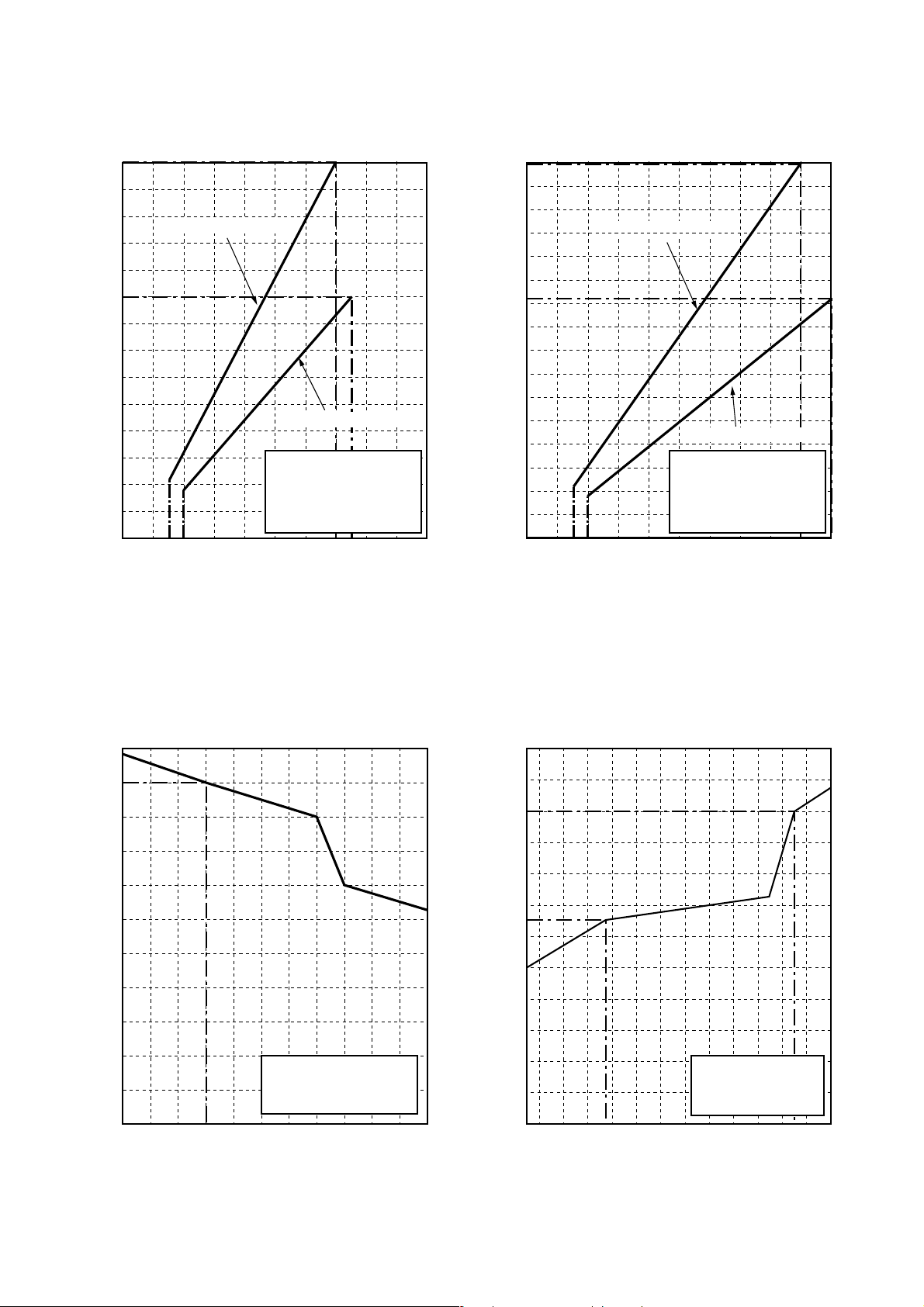
• Operation characteristic curve
<Cooling> <Heating>
14
12
RAV-SM800XT-E
10
8
6
Current (A)
4
2
0
15
020
RAV-SM560XT-E
• Conditions
Indoor : DB27˚C/WB19˚C
Outdoor : DB35˚C
Air flow : High
Pipe length : 7.5m
230V
40 60 70 80 100
Compressor speed (rps)
14
12
10
8
Current (A)
6
4
2
0
15
020
RAV-SM800XT-E
RAV-SM560XT-E
• Conditions
Indoor : DB20˚C
Outdoor : DB7˚C/WB6˚C
Air flow : High
Pipe length : 7.5m
230V
40 60 80 90 100
Compressor speed (rps)
• Capacity variation ratio according to temperature
<Cooling> <Heating>
105
100
95
90
120
110
100
90
80
85
70
80
60
75
70
Capacity ratio (%)
65
60
55
• Conditions
Indoor : DB27˚C/WB19˚C
Indoor air flow : High
Pipe length : 7.5m
50
32 33 34 35 36 37 38 39 40 41 42 43
50
40
Capacity ratio (%)
30
20
10
0
-14-12-10-8-6-4-20246810
Outsoor temp. (˚C)
• Conditions
Indoor : DB20˚C
Indoor air flow : High
Pipe length : 7.5m
Outsoor temp. (˚C)
–2 –
Page 5
1-2.Outdoor Unit
Model name
Appearance
Power supply
Type
Compressor Motor (kW)
Pole
Refrigerant charged (kg)
Refrigerant control
Standard length
Max. total length (m)
Pipe Over 20m
Outdoor lower (m)
Outdoor higher (m)
Outer
dimension
Height difference
Height (mm)
Width (mm)
Depth (mm)
RAV-SM560AT-E RAV-SM800AT-E
Silky shade (Muncel 1Y8.5/0.5)
1 phase 230V (220 – 240V) 50Hz
(Power exclusive to outdoor is required.)
Hermetic compressor
1.1 1.6
4 poles
R410A 0.9 R410A 1.5
Pulse motor valve
20 (without additional charge)
30 50
Add 20g/m (Max. 200g) Add 40g/m (Max. 1200g)
15
30
595 795
780 780
270 270
Total weight (kg)
Heat exchanger
Fan
Fan unit Standard air flow High (m³/h)
Motor (W)
Connecting
pipe
Protection device
Sound level High (Mid./Low)
(Note 2) (Cooling/Heating)
Gas side (mm)
Liquid side (mm)
(dB•A)
35 55
Finned tube
Propeller fan
2400 3400
43 63
Ø12.7 (1/2”) Ø15.9 (5/8”)
Ø6.4 (1/4”) Ø9.5 (3/8”)
Discharge temp. sensor
Over-current sensor
Compressor thermo.
46/48 48/50
Note 1 : The sound level is measured in an anechoic chamber in accordance with JIS B8616.Nor mally, the values measured in
the actual operating environment become larger than the indicated values due to the effects of external sound.
Note 2 : Rated conditions Cooling :Indoor air temperature 27°C DB/19°C WB, Outdoor air temperature 35°C DB
Heating : Indoor air temperature 20°C DB, Outdoor air temperature 7°C DB/6°C WB
– 3 –
Page 6
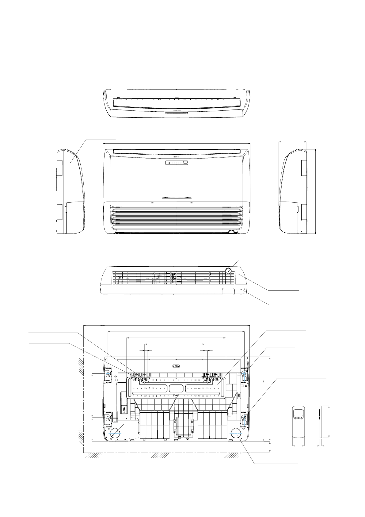
2-1. Indoor Unit
2. CONSTRUCTIONVIEWS
Front panel
1093
208
633
Knock out system
Grille air inlet
Back body
For stud bolt
(Ø8 – Ø10)
For stud bolt (Ø6)
200 Min
330165
1093
1015
742
450
20 20
Ø74
UNDER CEILING & CONSOLE INSTALLATION
– 4 –
Installation plate
Mount plate
M10 Suspention bolt
633
460
70 Min
Wireless remote control
Knock out system
160
57 18
Page 7
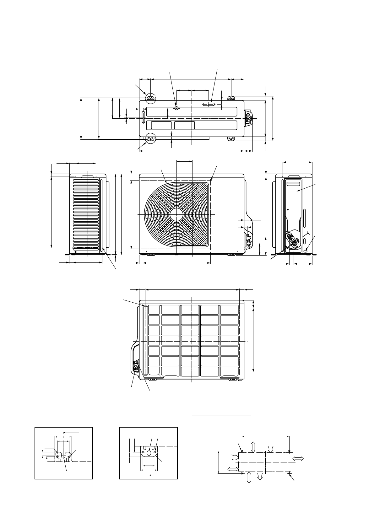
2-2.Outdoor Unit (RAV-SM560AT-E)
49.5
521 21
25 220
308
302
Ø6 hole pitch
For anchor bolt)
(Long hole pitch
147
Drain hole (Ø25)
83
A legs
150
11
30
76
153
B legs
Discharge guard
(49.3)
598
593
500 (Fan center dividing)
500 (Fan center dividing)
Protective net mounting hole
(2-Ø4 embossing)
Drain hole (2-Ø20 x 88 long hole)
600
115.3 125
30
21
780
115.3
Discharge guide mounting hole
(4-Ø4 embossing)
97
2927031
330
21
31
23
132
90.6
Charge port
216
31 134
Valve cover
Earth
terminal
43 707 30
Protective net mounting hole
(4-Ø4 embossing)
Refrigerant pipe connecting port
(Ø12.7 flare at gas side)
600
52
36
R15
302
308 11
Ø11 x 14 U-shape hole
Details of A legs Details of B legs
2-Ø6 hole
Product
external line
Ø11 x 14 Ushape holes
308
302
11
Refrigerant pipe connecting port
(Ø6.4 flare at liquid side)
Space required for service
2-Ø11 x 14 U-shape holes
(For Ø8–Ø10 anchor bolt)
36
52
2-Ø6 hole
Product
external
line
R15
600
– 5 –
150
or more
365
500
or more
60
475
Suction port
150
or more
Discharge
port
600
300
or more
Discharge
port
(Minimum
distance up to wall)
2-Ø11 x 14 long hole
(For Ø8–Ø10 anchor bolt)
Page 8
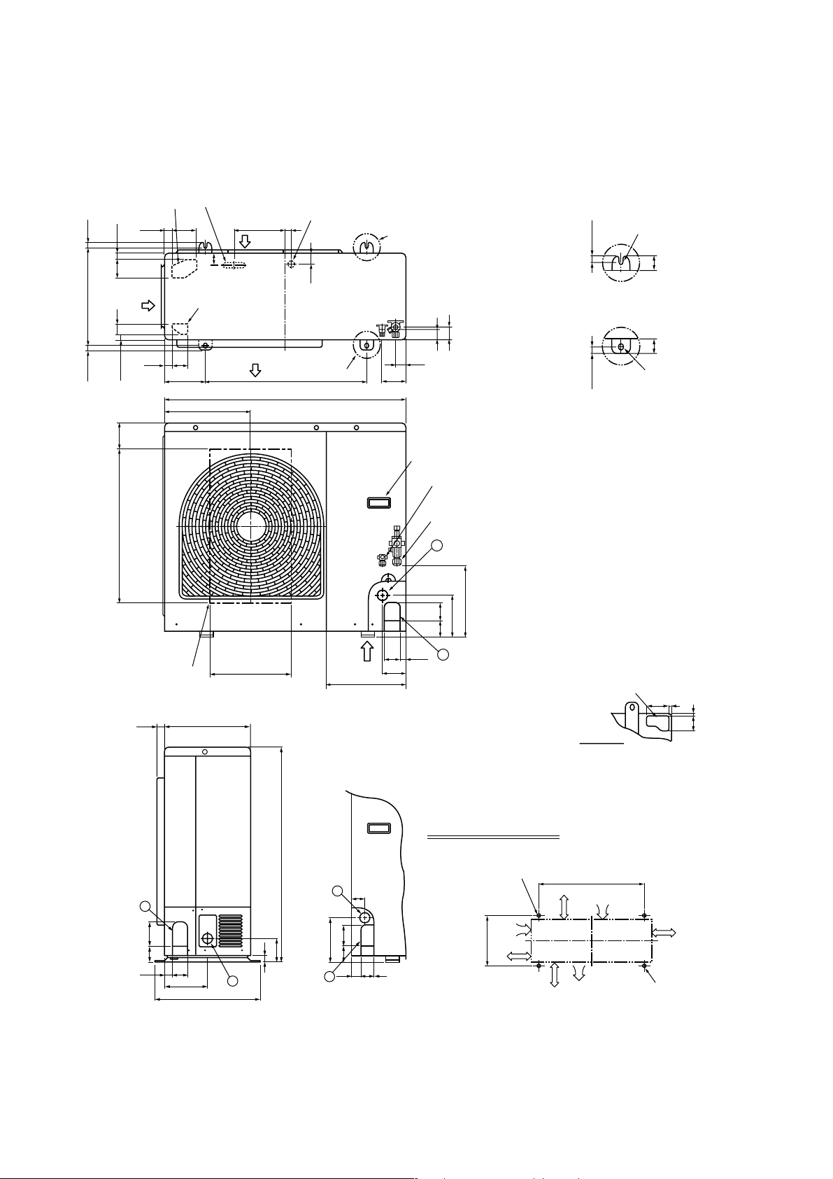
2-3.Outdoor Unit (RAV-SM800AT-E)
Knockout
(For draining)
21
Suction
port
365 17.517.5
40 70
(Long hole pitch
for anchor bolt)
21
565 101
Drain hole (Ø20 x 88 burring hole)
29 90 191 20
Suction
port
43
Knockout
(For draining)
6026
Discharge
port
300150
900
314
Drain hole (Ø25 burring hole)
Part B
40
39
Part A
43
95
Handles
(Both sides)
Refrigerant pipe connecting port
(Ø9.5 flare at liquid side)
Refrigerant pipe connecting port
(Ø15.9 flare at gas side)
2
47
Installation bolt hole
(Ø12 x 17 U-shape holes)
17.5
4040
Details of B part
Details of A part
17.5
Installation bolt hole
(Ø12 x 17 U-shape holes)
Discharge guide
mounting hole
(4-Ø4 embossing)
1
60 90
58
27
161
32028
400
264
6760
154
2760
300
Z
307
96
1
Knockout for lower piping
86 7
7
58
Z views
Space required for service
795
2
46
25
85
2
165
60 80
30 45
1
2-Ø12 x 17 U-shape holes
(For Ø8–Ø10 anchor bolt)
150
or more
365
500
or more
Suction port
150
or more
Discharge
port
600
150
or more
Discharge
port
(Minimum
distance up to wall)
2-Ø12 x 17 long hole
(For Ø8–Ø10 anchor bolt)
– 6 –
Page 9
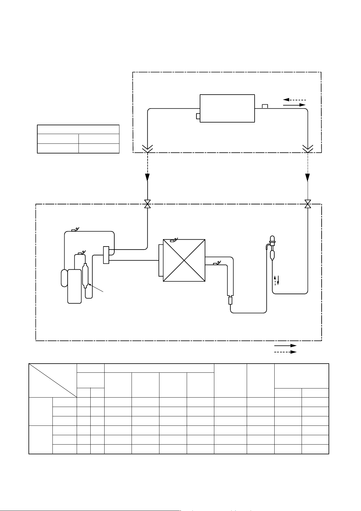
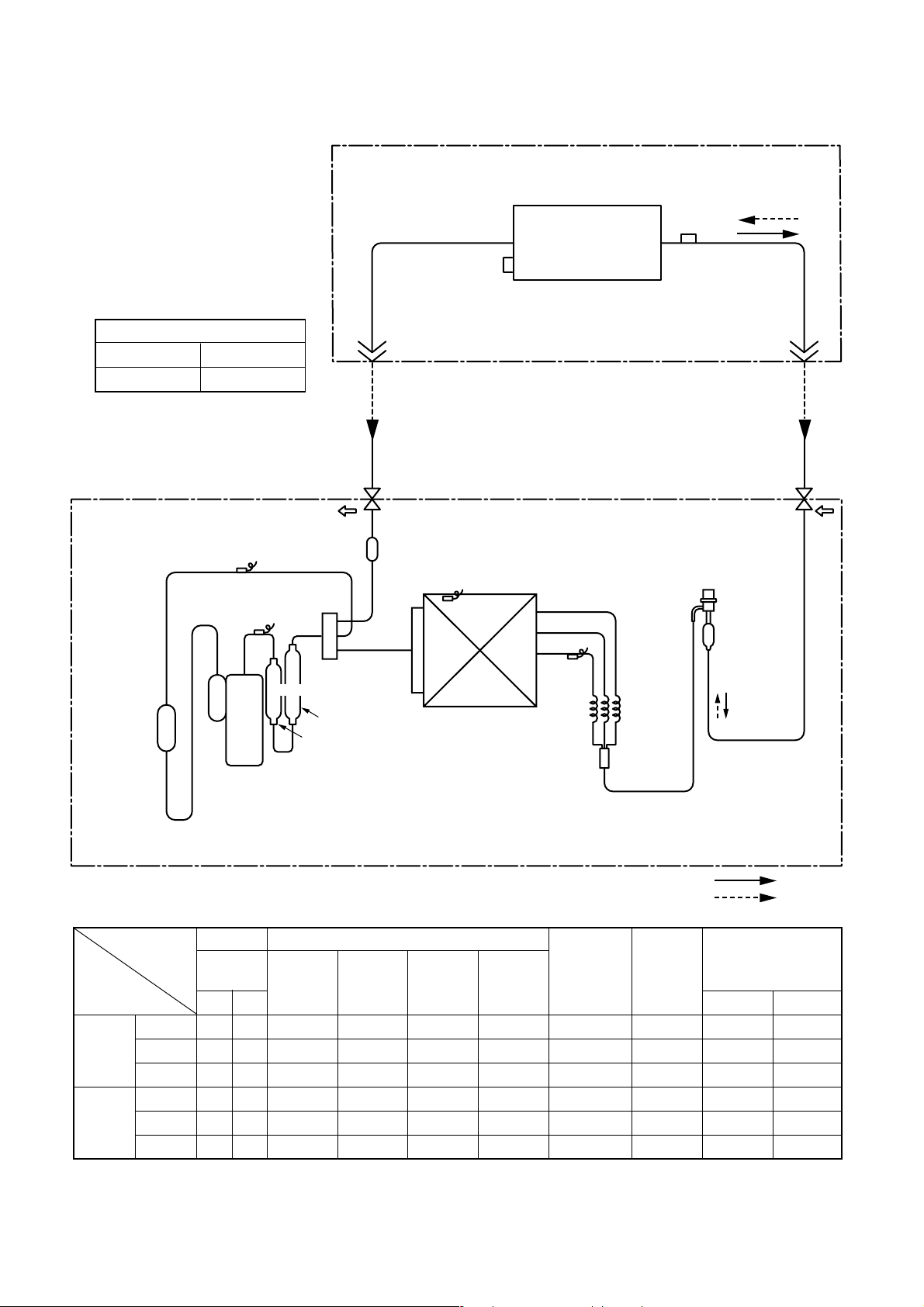
3. SYSTEMATIC REFRIGERATING CYCLE DIAGRAM
3-1.RAV-SM560XT-E / RAV-SM560AT-E
Outer diameter of refrigerant pipe
Gas side ∅A Liquid side ∅B
6.4 mm 12.7 mm
Indoor unit
TCJ
sensor
Air heat exchanger
TC sensor
TS sensor
TD sensor
Rotary compressor
(DA130A1F-23F)
4-way valve
(VT7101D)
Muffler
∅19 x L160
Refrigerant pipe
at liquid side
Outer dia. ∅B
Packed valve
Outer dia. ∅B
TO sensor
Heat exchanger
∅8 multiple thread
ripple 1 row 22 stages
FP1.3 flat fin
Outdoor unit
TE
sensor
Distributor
Refrigerant pipe
at gas side
Outer dia. ∅A
Max
30m
Packed valve
Outer dia. ∅A
PMV
(SKV-18D26)
Strainer
R410A 0.9 kg
Cooling
Heating
Pressure Pipe surface temperature (°C)
(MPa) Discharge Suction
Pd Ps (TD) (TS) (TC) (TE) Indoor Outdoor
Standard 3.1 0.9 85 13 10 47 74 HIGH 27/19 35/–
Cooling Overload 3.8 1.0 96 13 12 60 71 HIGH 32/24 43/–
Low load 0.9 0.5 25 7 10 5 28 LOW 18/15.5 –5/–
Standard 2.8 0.6 87 3 46 1 87 HIGH 20/– 7/6
Heating Overload 3.3 1.1 78 22 55 16 55 LOW 30.– 24/18
Low load 1.7 0.2 110 –20 26 –22 110 HIGH 0 –20/(70%)
Indoor heat Outdoor heat Indoor
exchanger exchanger fan
Compressor
revolutions
per second
(rps)
*
Indoor/Outdoor
temp. conditions
(DB/WB) (°C)
* 4 poles are provided to this compressor.
The compressor frequency (Hz) measured with a clamp meter is 2 times of revolutions (rps) of the compressor.
– 7 –
Page 10
3-2.RAV-SM800XT-E / RAV-SM800AT-E
Outer diameter of refrigerant pipe
Gas side ∅A Liquid side ∅B
9.5 mm 15.9 mm
TS sensor
Refrigerant pipe
at liquid side
Outer dia. ∅B
Packed valve
Outer dia. ∅B
Strainer
TC sensor
TO sensor
Indoor unit
Air heat exchanger
Outdoor unit
TCJ
sensor
Refrigerant pipe
at gas side
Outer dia. ∅A
Packed valve
Outer dia. ∅A
Modulating (PMV)
(SKV-18D26)
Max
50m
PsPd
TD sensor
Strainer
TE
sensor
Capillary
∅3 x ∅2
x L530
Accumulator
(1500cc)
Muffler
4-way valve
(STF-0213Z)
∅25 x L210
∅25 x L160
Heat exchanger∅8
1 row 30 stages
FP1.3 flat fin
Rotary compressor
(DA220A2F-20L)
R410A 1.5 kg
Cooling
Heating
Pressure Pipe surface temperature (°C)
(MPa) Discharge Suction
Pd Ps (TD) (TS) (TC) (TE) Indoor Outdoor
Standard 3.3 0.9 89 8 8 40 64 HIGH 27/19 35/–
Cooling Overload 3.7 1.1 87 17 14 46 45 HIGH 32/24 43/–
Low load 1.0 0.8 22 2 1 1 24 LOW 18/15.5 –5/–
Standard 3.3 0.6 93 0 54 0 70 HIGH 20/– 7/6
Heating Overload 3.1 1.1 75 20 52 15 24 LOW 30.– 24/18
Low load 2.0 0.2 90 –26 25 –25 90 HIGH 0 –20/(70%)
Indoor heat Outdoor heat Indoor
exchanger exchanger fan
Compressor
revolutions
per second
(rps)
*
Indoor/Outdoor
temp. conditions
(DB/WB) (°C)
* 4 poles are provided to this compressor.
The compressor frequency (Hz) measured with a clamp meter is 2 times of revolutions (rps) of the compressor.
– 8 –
Page 11
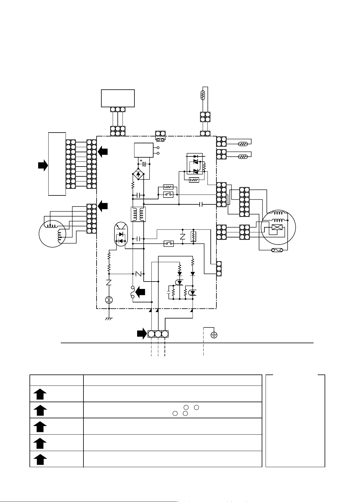
4-1. Indoor Unit
10
10
9
9
8
8
7
7
6
1
LOUVER
MOTOR
6
5
5
4
4
3
3
2
2
1
1
AND INDICATION PARTS
CN25
INFRARED RAYS RECEIVE
WHI
BLU
BLU
BLU
BLU
BLU
BLU
BLU
BLU
BLU
BRW
RED
ORN
YEL
PNK
BLU
10
9
8
7
6
5
4
3
2
1
CN13
1
2
3
4
5
CN07
10
9
8
7
6
5
4
3
2
1
1
2
3
4
5
66
SWITCH PCB
MCC-1428B
CN101
WHI
CN100
4
5
IC04
R507
R09
R22
SG01
21 3
GRY
GRY
21 3
21
3
DB01
R01
FUSE
250VAC
F01
T6.3A
4. WIRING DIAGRAM
HEAT
EXCHANGER
SENSOR
(TCJ)
FOR FLOAT SWITCH
(OPTION)
When you use float
switch you should cut J401
C02
C15
CN402
POWER
SUPPLY
CIRCUIT
C01
R21
3
21
J401
DC12V
DC5V
CR502
RY501
MCC-1428A
R405
RY401
CN05
IC03
CR501
C501
CR401
21
21
CN03
21
2
121
2
121
CN01
R506
1
1
2
2
3
3
4
4
5
5
CN10
3
3
2
2
1
1
CN11
3
FOR DRAIN PUMP
2
1
CN401
BLK
BLK
BLK
BLK
WHI
RED
BLK
BRW
GRY
YEL
(OPTION)
1
1
2
2
3
3
4
4
5
5
66
3
3
2
2
1
1
THERMO
SENSOR
(TA)
HEAT
EXCHANGER
SENSOR
(TC)
WHI
RED
BLK
BLU
PUR
GRY
FAN-MOTOR
100”C
Check items
OPERATION
1
indicator
Terminal
2
block
Fuse
3
6.3A
DC 5V
4
DC 12V
5
BLK
P04
CN30
2
BLK
CN31
WHI
21 3
RED
INDOOR
TERMINAL
BLOCK
CN23
GRN&YEL
SIMPLE CHECK POINTS FOR DIAGNOSING FAULTS
Diagnosis result
Check to see if OPERATION indicator goes on and off when the main switch
or breaker is turned on.
Check the power supply voltage between 1 - 2 (Refer to the name plate.)
Chack the fluctuate voltage between 2 - 3 (DC15 to 60V)
Check to see if the fuse blows out. (Check the varistor. : R22, R21)
Check the voltage at the No.8 pin on CN13 connector of the infrared receiver.
(Check the transformer and the power supply circuit of the rated voltage.)
Check the voltage at the brown lead of the louver motor.
(Check the transformer and the power supply circuit of the rated voltage.)
– 9 –
INDOOR
UNIT
OUTDOOR
UNIT
Identification
BRW
RED
GRY
PNK
ORN
GRN&YEL
GRN
PUR
Color
WHI
YEL
BLU
BLK
BROWN
:
RED
:
WHITE
:
YELLOW
:
BLUE
:
BLACK
:
GRAY
:
PINK
:
ORANGE
:
GREEN&
:
YELLOW
GREEN
:
PURPLE
:
Page 12
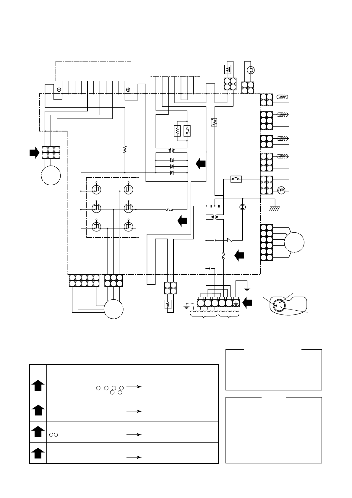
4-2. Outdoor Unit (RAV-SM560AT-E)
Q200
BLU
P17 P18
P21
P22
P23
RED
WHI
BLK
4
2 1
233 1
CM
COMPRESSOR
CN301
IGBT MODULE
BZBYBXEWBWEVBVEUBU
P.C. BOARD
(MCC-813)
5
5
GRY
4 3
PNK
2 1
YEL
3
3
BLK
2 1
2 1
WHI
RED
2 1
4 3
FM
FAN MOTOR
Q300
CN300
BRW
P19P20
P14
PUR
REACTOR
DB01
CONVERTER
MODULE
~
~
–
+
ELECTRONIC
STARTER
–
–
–
F04
FUSE
T3. 15A
250V~
P13
P12
2 1
2 1
+
+
+
P11
2
GEA
P10
POWER
RELAY
C12
3
C13
C14
P02
1
TO
INDOOR
UNIT
REACTOR
ORN
P09
P08 P07
CT
FUSE
T25A
250V~
P03
ORN
WHI
2
3
L
POWER
SUPPLY
220 to 240
50Hz
2 1
2 1
RELAY
VARISTOR
F01
P01
BLK
N
2 1
2 1
CN600
CN601
CN602
CN603
CN701
P06
SURGE
ABSORBER
2
1
THERMOSTAT
FOR
COMPRESSOR
CN500
TE
11
22
TD
11
22
33
TO
11
22
TS
11
22
33
11
22
33
COIL FOR
11
22
33
44
55
66
BLK
YEL
RED
ORN
RED
GRY
4-WAY VALVE
PMV
PULSE
MODULATING
VALVE
BLACK (C)
BLK
CN703
TERMINAL OF COMPRESSOR
WHITE (S)
The sign in ( ) is displayed
in the terminalcover
RED (R)
Check
items
1
2
3
4
SIMPLE CHECK POINTS FOR DIAGNOSING FAULTS
Diagnosis result
TERMINAL BLOCK
There is no supply voltage
(AC220 to 240V) between L - N , 1 - 2
There is no voltage (DC15 to 25V) 2 - 3
FUSE
T25A 250V to fuse (F01) blown
T3.15A 250V to fuse (F04) blown
ELECTROLYTIC CAPACITOR VOLTAGE (C12, C13, C14)
DC320V not available between
+ – terminal of electrolytic capacitor
INVERTER OUTPUT (Inverter and compressor connector out of position)
(Please confirm within six minutes after instructing in the drive.)
Voltage between each line of in v erter side
conector pins are not equal.
Power supply and connecting
cable check
Converter module (DB01) and
electrolytic capacitor (C12 to C14) check
IGBT module (Q200) check
Fan motor check
T25A fuse (F01) check
P.C. board and converter
module (DB01) check
IGBT module and
P.C. board check
– 10 –
Color Identification
BLK
BLU
RED
GRY
PNK
GRN
BLACK
:
BLUE
:
RED
:
GRAY
:
PINK
:
GREEN
:
WHI
BRW
ORN
YEL
PUR
NOTE
CM
: Compressor
PMV
: Pulse modulating valve
FM
: Fan motor
TE
: Heat exchanger Temp. Sensor
TD
: Discharge Temp. Sensor
TO
: Outdoor Temp. Sensor
TS
: Suction Temp. Sensor
IGBT
: Insulated Gate Bipolar Transistor
: Converter module
DB01
: Curreut Transformer
CT
: Fan motor driver module
Q300
WHITE
:
BROWN
:
ORANGE
:
YELLOW
:
PURPLE
:
Page 13
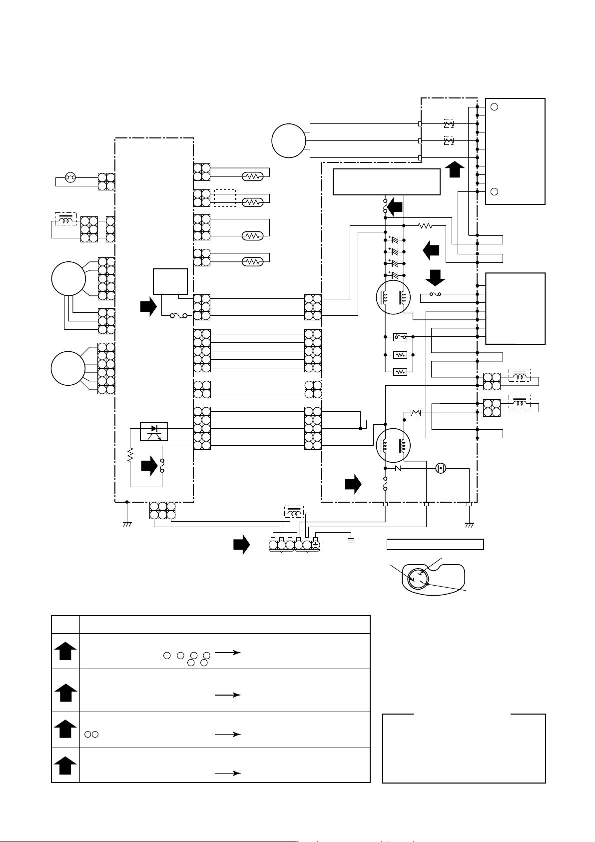
4-3. Outdoor Unit (RAV-SM800AT-E)
THERMOST AT
FOR
COMPRESSOR
ORN
212
ORN
4-WAY VAL VE COIL
313
3
1
1
FAN MOTOR
5
4
FM
1
3
2
1
6
5
PMV
SUB
P.C. BOARD
(MCC-1398)
4
3
2
1
SIMPLE CHECK POINTS FOR DIAGNOSING FAULTS
CN500
1
CN700
5
4
CN300
3
232
1
3
2
1
6
5
4
3
2
1
2
CN301
CN702
PHOTO COUPLER
2
CN02
Fan
circuit
CN302
F300
FUSE
T5A
CN800
2 31
2 31
Compressor
212
CN604
CN605
CN600
CN601
CN04
CN01
F01
FUSE
T3.15A
1
212
GRN
1
3
2
131
212
1
313
1
5 5 5 5
4 4 4 4
3 3 3 3
212
1
212
1
5 5 5 5
4 4 4 4
3 3 3 3
212
1
GRY
WHI
BLU
YEL
BLK
WHI
BLU
RED
PNK
ORN
BLK
WHI
RED
RED
1
CM
TE
TS
TD
TO
REACTOR
TO
INDOOR
UNIT
313
212
212
212
L N2 31
POWER
SUPPL Y
220-240V
~50Hz
RED
WHI
BLK
POWER SUPPLY CIRCUIT
(FOR P.C. BOARD)
F04
FUSE
3.15A
CN04
1
CN06
P.C. BOARD
1
(MCC-1359)
CN05
1
1
CN13
F01
FUSE
2
25A
WHITE(S)
+
BU
EU
BV
EV
BW
EW
BX
BY
BZ
CN09
CN10
CN11
T03
CT
T04
CT
4
2
P20
P10
P11
P13
P12
P09
P08
P15
P14
CN03
BLKWHIRED
P19
P18
P17
G
E
A
~
~
+
REACTOR
212
REACTOR
212
RED(R)
C13
3
C12
C11
C10
POWER
RELAY
RY01
R05
R06
T02
CT
VARISTOR
CN02CN01
TERMINAL OF COMPRESSOR
F02
2
FUSE
15A
SURGE
ABSORBER
BLACK(C)
IGBT
module
Q200
YEL
BLU
Converter
module
DB01
ORN
1
1
BRN
The sign in ( )
is displayed
in the terminal
cover
Check
items
1
2
3
4
Diagnosis result
TERMINAL BLOCK
There is no supply voltage
(AC220 to 240V) between L - N , 1 - 2
There is no voltage (DC15 to 25V) 2 - 3
FUSE
25A fuse (F01) blown, 15A fuse (F02) blown
3.15A fuse (F04) blown,
T5A fuse (F300) blown (SUB P.C. board)
T3.15A fuse (F01) blown (SUB P.C. board)
ELECTROLYTIC CAPACITOR VOLTAGE (C10, C11, C12, C13)
DC320V not available between
+ terminal of electrolytic capacitor
INVERTER OUTPUT (CN09, CN10, CN11)
(Please confirm within six minutes after instructing in the drive.)
Voltage between each line of inverterside
conector pins are not equal.
Connecting cable check
Converter module (DB01) and electrolytic
capacitor (C10 to C13) check IGBT
module (Q200) check, Fan motor check
SUB P.C. board check
25A fuse (F01) check
P.C. board and coverter
module (DB01) check
IGBT module and
P.C. board check
– 11 –
Color Identification
:
BLK
BLU
RED
GRY
PNK
GRN
BLACK
:
BLUE
:
RED
:
GRAY
:
PINK
GREEN
:
WHI
BRN
ORN
YEL
PUR
:
WHITE
:
BROWN
:
ORANGE
:
YELLOW
:
PURPLE
Page 14
5. SPECIFICATION OF ELECTRICAL PARTS
5-1. Indoor Unit
No. Parts name Type Specifications
1 Fan motor (for indoor) AFP-220-50-4A Output (Rated) 50 W, 220 – 240 V
2 Grille motor MP35EA12 DC 12 V
3 Thermo. sensor (TA-sensor) 550 mm 10 kΩ at 25°C
4 Heat exchanger sensor (TC-sensor) ∅6 mm, 500 mm 10 kΩ at 25°C
5 Heat exchanger sensor (TCJ-sensor) ∅6 mm, 500 mm 10 kΩ at 25°C
5-2. Outdoor Unit (RAV-SM560AT-E)
No. Parts name Type Specifications
1 Fan motor ICF-140-43-1 Output (Rated) 40 W
2 Compressor DA130A1F-23F 3 phase, 4P, 1100 W
3 Reactor CH-57 1=10 mH, 16A
4 Outdoor temp. sensor (To-sensor) — 10 kΩ at 25°C
5 Heat exchanger sensor (Te-sensor) — 10 kΩ at 25°C
6 Suction temp. sensor (Ts-sensor) — 10 kΩ at 25°C
7 Discharge temp. sensor (Td-sensor) — 50 kΩ at 25°C
8 Fuse (Switching power (Protect)) — T3.15 A, AC 250 V
9 Fuse (Inverter, input (Current protect) — 25 A, AC 250 V
10 4-way valve solenoid coil STF-0108G
11 Compressor thermo. (Protection) US-622 ON : 90 ± 5°C, OFF : 125 ± 4°C
5-3. Outdoor Unit (RAV-SM800AT-E)
No. Parts name Type Specifications
1 Fan motor ICF-140-63-1 Output (Rated) 63 W, 220 – 240 V
2 Compressor DA220A2F-20L 3 phase, 4P, 1600 W
3 Reactor CH-47
4 Outdoor temp. sensor (To-sensor) — 10 kΩ at 25°C
5 Heat exchanger sensor (Te-sensor) — 10 kΩ at 25°C
6 Suction temp. sensor (Ts-sensor) — 10 kΩ at 25°C
7 Discharge temp. sensor (Td-sensor) — 50 kΩ at 25°C
8 Fuse (Switching power (Protect)) — T3.15 A, AC 250 V
9 Fuse (Inverter, input (Current protect) — 25 A, AC 250 V
10 4-way valve solenoid coil DKV-M0ZS743B0
11 Compressor thermo. (Protection) US-622 ON : 90 ± 5°C, OFF : 125 ± 4°C
– 12 –
Page 15

6. REFRIGERANT R410A
This air conditioner adopts the new refrigerant HFC
(R410A) which does not damage the ozone layer.
The working pressure of the new refrigerant R410A is
1.6 times higher than conventional refrigerant (R22).
The refrigerating oil is also changed in accordance
with change of refrigerant, so be careful that water,
dust, and existing refrigerant or refrigerating oil are not
entered in the refrigerant cycle of the air conditioner
using the new refrigerant during installation work or
servicing time.
The next section describes the precautions for air
conditioner using the new refrigerant. Conforming to
contents of the next section together with the general
cautions included in this manual, perform the correct
and safe work.
6-1. Safety During Installation/Servicing
As R410A’s pressure is about 1.6 times higher than
that of R22, improper installation/servicing may cause
a serious trouble. By using tools and materials exclusive for R410A, it is necessary to carry out installation/
servicing safely while taking the following precautions
into consideration.
(1) Never use refrigerant other than R410A in an air
conditioner which is designed to operate with
R410A.
If other refrigerant than R410A is mixed, pressure
in the refrigeration cycle becomes abnormally
high, and it may cause personal injury, etc. by a
rupture.
(2) Confirm the used refrigerant name, and use tools
and materials exclusive for the refrigerant R410A.
The refrigerant name R410A is indicated on the
visible place of the outdoor unit of the air conditioner using R410A as refrigerant. To prevent
mischarging, the diameter of the service port
differs from that of R22
(3) If a refrigeration gas leakage occurs during
installation/servicing, be sure to ventilate fully.
If the refrigerant gas comes into contact with fire,
a poisonous gas may occur.
(4) When installing or removing an air conditioner,
do not allow air or moisture to remain in the
refrigeration cycle. Otherwise, pressure in the
refrigeration cycle may become abnormally high
so that a rupture of personal injury may be
caused.
(5) After completion of installation work, check to
make sure that there is no refrigeration gas
leakage.
If the refrigerant gas leaks into the room, coming
into contact with fire in the fan-driven heater,
space heater, etc., a poisonous gas may occur.
(6) When an air conditioning system charged with a
large volume of refrigerant is installed in a small
room, it is necessary to exercise care so that,
even when refrigerant leaks, its concentration
does not exceed the marginal level.
If the refrigerant gas leakage occurs and its
concentration exceeds the marginal level, an
oxygen starvation accident may result.
(7) Be sure to carry out installation or removal
according to the installation manual.
Improper installation may cause refrigeration
trouble, water leakage, electric shock, fire, etc.
(8) Unauthorized modifications to the air conditioner
may be dangerous. If a breakdown occurs please
call a qualified air conditioner technician or
electrician.
Improper repair’s may result in water leakage,
electric shock and fire, etc.
6-2. Refrigerant Piping Installation
6-2-1. Piping materials and joints used
For the refrigerant piping installation, copper pipes and
joints are mainly used. Copper pipes and joints suitable for the refrigerant must be chosen and installed.
Furthermore, it is necessary to use clean copper pipes
and joints whose interior surfaces are less affected by
contaminants.
(1) Copper pipes
It is necessary to use seamless copper pipes
which are made of either copper or copper alloy
and it is desirable that the amount of residual oil is
less than 40 mg/10 m. Do not use copper pipes
having a collapsed, deformed or discolored
portion (especially on the interior surface).
Otherwise, the expansion valve or capillary tube
may become blocked with contaminants.
As an air conditioner using R410A incurs pressure
higher than when using R22, it is necessary to
choose adequate materials.
Thicknesses of copper pipes used with R410A are
as shown in Table 6-2-1. Never use copper pipes
thinner than 0.8 mm even when it is available on
the market.
– 13 –
Page 16
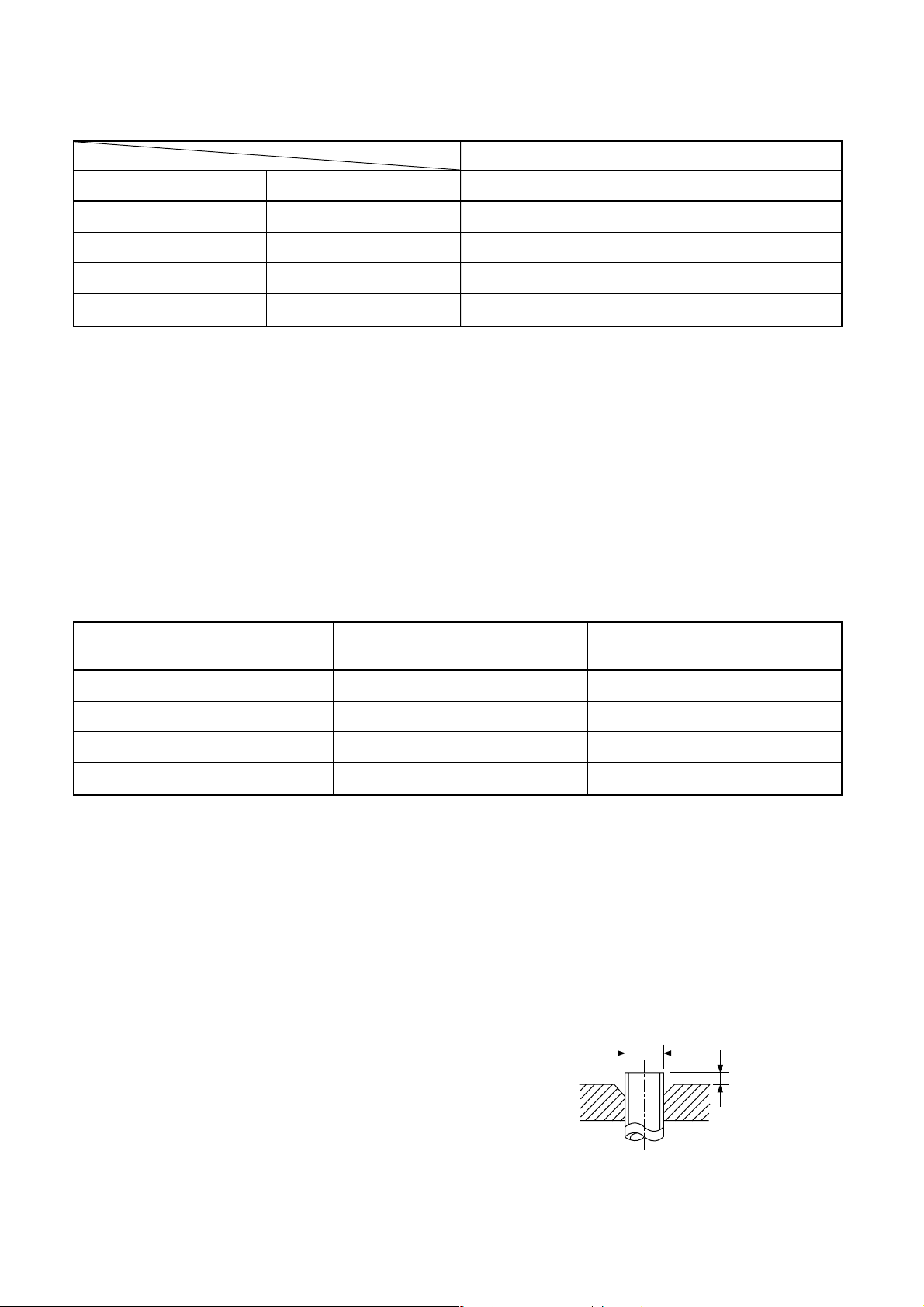
Table 6-2-1 Thicknesses of annealed copper pipes
Thickness (mm)
Nominal diameter Outer diameter (mm) R410A R22
1/4 6.35 0.80 0.80
3/8 9.52 0.80 0.80
1/2 12.70 0.80 0.80
5/8 15.88 1.00 1.00
(2) Joints
For copper pipes, flare joints or socket joints are
used. Prior to use, be sure to remove all
contaminants.
a) Flare joints
Flare joints used to connect the copper pipes
cannot be used for pipings whose outer
diameter exceeds 20 mm. In such a case,
socket joints can be used.
Sizes of flare pipe ends, flare joint ends and
flare nuts are as shown in Tables 6-2-3 to 6-2-6
below.
Table 6-2-2 Minimum thicknesses of socket joints
Nominal diameter
Reference outer diameter of Minimum joint thickness
1/4 6.35 0.50
3/8 9.52 0.60
1/2 12.70 0.70
5/8 15.88 0.80
b) Socket joints
Socket joints are such that they are brazed for
connections, and used mainly for thick pipings
whose diameter is larger than 20 mm.
Thicknesses of socket joints are as shown in
Table 6-2-2.
copper pipe jointed (mm) (mm)
6-2-1. Processing of piping materials
When performing the refrigerant piping installation,
care should be taken to ensure that water or dust does
not enter the pipe interior, that no other oil other than
lubricating oils used in the installed air conditioner is
used, and that refrigerant does not leak. When using
lubricating oils in the piping processing, use such
lubricating oils whose water content has been removed.
When stored, be sure to seal the container with an
airtight cap or any other cover.
(1) Flare Processing procedures and precautions
a) Cutting the pipe
By means of a pipe cutter, slowly cut the pipe
so that it is not deformed.
b) Removing burrs and chips
If the flared section has chips or burrs,
refrigerant leakage may occur. Carefully
remove all burrs and clean the cut surface
before installation.
c) Insertion of flare nut
– 14 –
d) Flare processing
Make certain that a clamp bar and copper pipe
have been cleaned.
By means of the clamp bar, perform the flare
processing correctly.
Use either a flare tool for R410A or conventional flare tool.
Flare processing dimensions differ according to
the type of flare tool. When using a conventional flare tool, be sure to secure “dimension A”
by using a gauge for size adjustment.
∅D
A
Fig. 6-2-1 Flare processing dimensions
Page 17
Table 6-2-3 Dimensions related to flare processing for R410A
A (mm)
Conventional flare tool
Clutch type Wing nut type
Nominal
diameter
Outer
diameter
(mm)
Thickness
(mm)
Flare tool for R410A
clutch type
1/4 6.35 0.8 0 to 0.5 1.0 to 1.5 1.5 to 2.0
3/8 9.52 0.8 0 to 0.5 1.0 to 1.5 1.5 to 2.0
1/2 12.70 0.8 0 to 0.5 1.0 to 1.5 2.0 to 2.5
5/8 15.88 1.0 0 to 0.5 1.0 to 1.5 2.0 to 2.5
Table 6-2-4 Dimensions related to flare processing for R22
A (mm)
Conventional flare tool
Clutch type Wing nut type
Nominal
diameter
Outer
diameter
(mm)
Thickness
(mm)
Flare tool for R22
clutch type
1/4 6.35 0.8 0 to 0.5 0.5 to 1.0 1.0 to 1.5
3/8 9.52 0.8 0 to 0.5 0.5 to 1.0 1.0 to 1.5
1/2 12.70 0.8 0 to 0.5 0.5 to 1.0 1.5 to 2.0
5/8 15.88 1.0 0 to 0.5 0.5 to 1.0 1.5 to 2.0
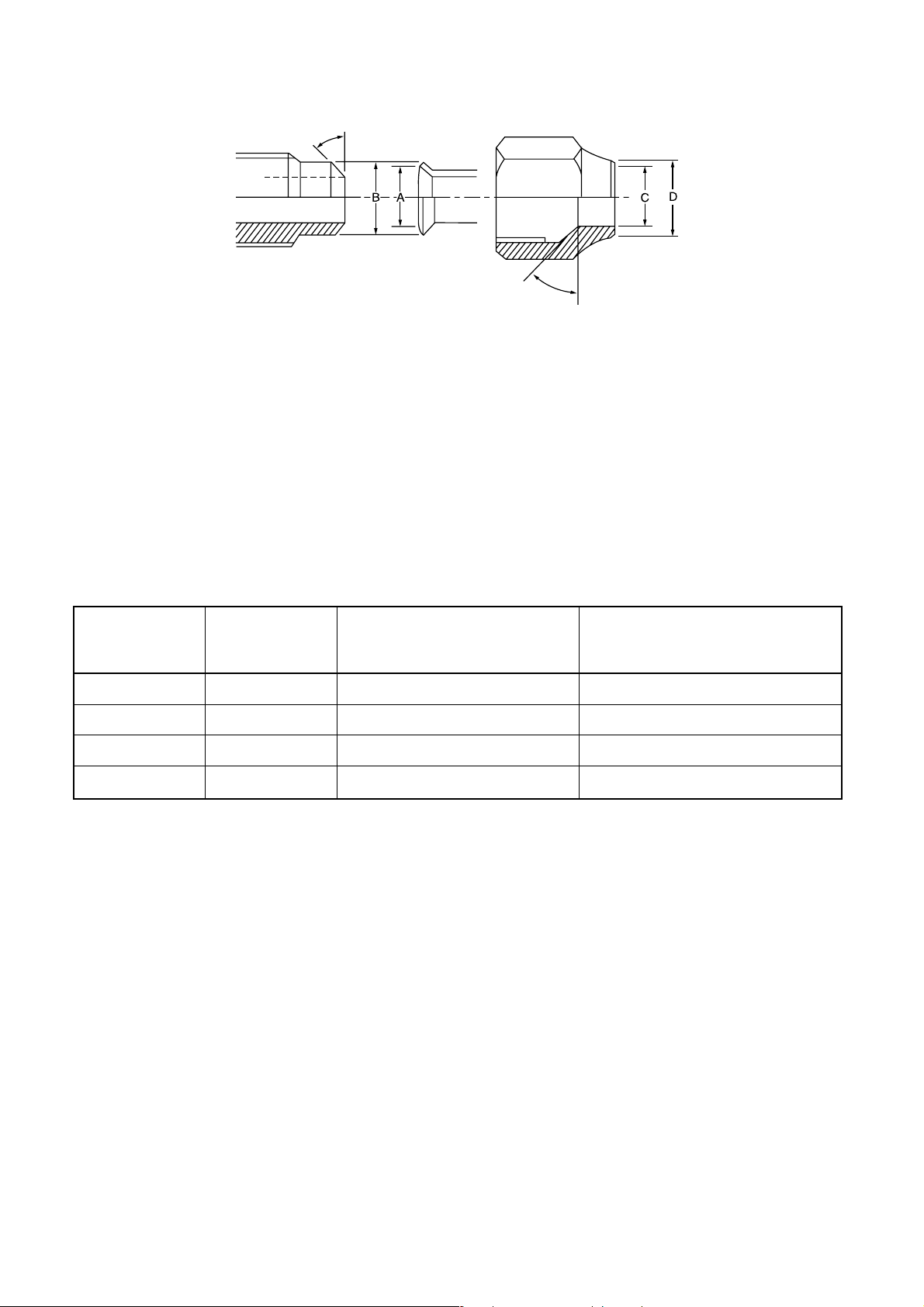
Table 6-2-5 Flare and flare nut dimensions for R410A
Nominal
diameter
Outer
diameter
(mm)
Thickness
(mm)
Dimension (mm)
ABCD
Flare nut
width
(mm)
1/4 6.35 0.8 9.1 9.2 6.5 13 17
3/8 9.52 0.8 13.2 13.5 9.7 20 22
1/2 12.70 0.8 16.6 16.0 12.9 23 26
5/8 15.88 1.0 19.7 19.0 16.0 25 29
Table 6-2-6 Flare and flare nut dimensions for R22
Nominal
diameter
Outer
diameter
(mm)
Thickness
(mm)
Dimension (mm)
ABCD
Flare nut
width
(mm)
1/4 6.35 0.8 9.0 9.2 6.5 13 17
3/8 9.52 0.8 13.0 13.5 9.7 20 22
1/2 12.70 0.8 16.2 16.0 12.9 20 24
5/8 15.88 1.0 19.4 19.0 16.0 23 27
3/4 19.05 1.0 23.3 24.0 19.2 34 36
– 15 –
Page 18
°
° to 46
45
43° to 45°
Fig. 6-2-2 Relations between flare nut and flare seal surface
(2) Flare connecting procedures and precautions
a) Make sure that the flare and union portions do
not have any scar or dust, etc.
b) Correctly align the processed flare surface with
the union axis.
c) Tighten the flare with designated torque by
means of a torque wrench. The tightening
torque for R410A is the same as that for
conventional R22. Incidentally, when the torque
is weak, the gas leakage may occur.
Table 6-2-7 Tightening torque of flare for R410A [Reference values]
Nominal Outer diameter Tightening torque
diameter (mm) N·m (kgf·cm)
1/4 6.35 14 to 18 (140 to 180) 16 (160), 18 (180)
3/8 9.52 33 to 42 (330 to 420) 42 (420)
1/2 12.70 50 to 62 (500 to 620) 55 (550)
5/8 15.88 63 to 77 (630 to 770) 65 (650)
When it is strong, the flare nut may crack and
may be made non-removable. When choosing
the tightening torque, comply with values
designated by manuf acturers. Table 6-2-7
shows reference values.
Note:
When applying oil to the flare surface, be sure to use
oil designated by the manufacturer. If any other oil is
used, the lubricating oils may deteriorate and cause
the compressor to burn out.
Tightening torque of torque
wrenches available on the market
N·m (kgf·m)
– 16 –
Page 19
6-3. T ools
6-3-1. Required tools
The service port diameter of packed valve of the outdoor unit in the air conditioner using R410A is changed to
prevent mixing of other refrigerant. To reinforce the pressure-resisting strength, flare processing dimensions and
opposite side dimension of flare nut (For ∅12.70 copper pipe) of the refrigerant piping are lengthened.
The used refrigerating oil is changed, and mixing of oil may cause a trouble such as generation of sludge,
clogging of capillary, etc. Accordingly, the tools to be used are classified into the following three types.
(1) Tools exclusive for R410A (Those which cannot be used for conventional refrigerant (R22))
(2) Tools exclusive for R410A, but can be also used for conventional refrigerant (R22)
(3) Tools commonly used for R410A and for conventional refrigerant (R22)
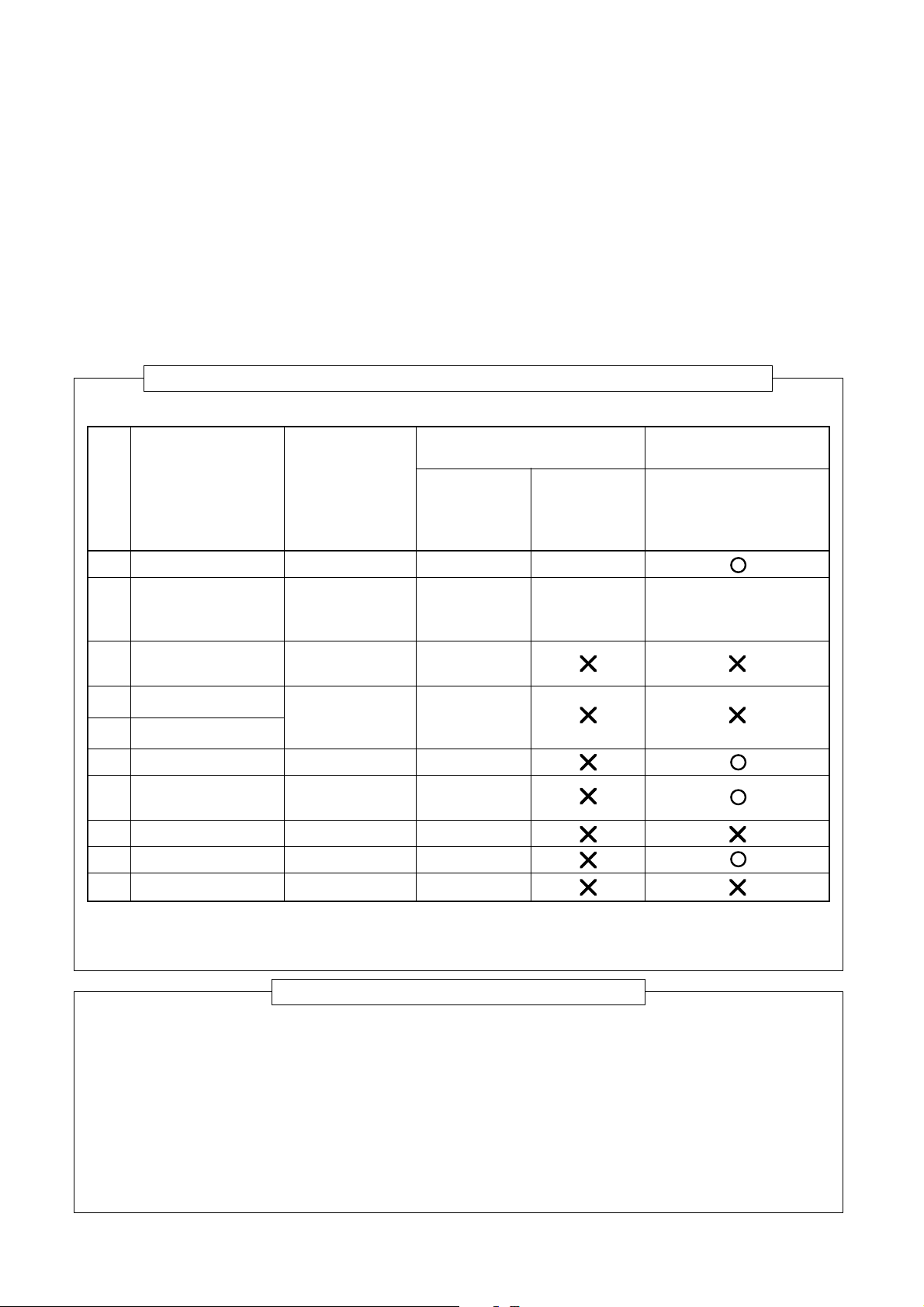
The table below shows the tools exclusive for R410A and their interchangeability.
Tools exclusive for R410A (The following tools for R410A are required.)
Tools whose specifications are changed for R410A and their interchangeability
R410A air conditioner Conventional air
installation conditioner installation
No. Used tool Usage Existence of Whether Whether new equipment
new equipment conventional can be used with
for R410A equipment can conventional refrigerant
be used
1 Flare tool Pipe flaring Yes *(Note 1)
2 Copper pipe gauge Flaring by
for adjusting projection conventional flare Yes *(Note 1) *(Note 1)
margin tool
3 Torque wrench
4 Gauge manifold
5 Charge hose
6 Vacuum pump adapter Vacuum evacuating Yes
Electronic balance for
7
refrigerant charging
8 Refrigerant cylinder Refrigerant charge Yes
9 Leakage detector Gas leakage check Yes
! Charging cylinder Refrigerant charge (Note 2)
Connection of
flare nut
Evacuating,
refrigerant charge, Yes
run check, etc.
Refrigerant charge Yes
Yes
(Note 1) When flaring is carried out for R410A using the conventional flare tools, adjustment of projection
margin is necessary. For this adjustment, a copper pipe gauge, etc. are necessary.
(Note 2) Charging cylinder for R410A is being currently developed.
General tools (Conventional tools can be used.)
In addition to the above exclusive tools, the following equipments which serve also for R22 are necessary as
the general tools.
(1) Vacuum pump (4) Reamer (9) Hole core drill (∅65)
Use vacuum pump by (5) Pipe bender (10) Hexagon wrench
attaching vacuum pump adapter. (6) Level vial (Opposite side 4 mm)
(2) Torque wrench (7) Screwdriver (+, –) (11) Tape measure
(3) Pipe cutter (8) Spanner of Monkey wrench (12) Metal saw
Also prepare the following equipments for other installation method and run check.
(1) Clamp meter (3) Insulation resistance tester
(2) Thermometer (4) Electroscope
– 17 –
Page 20
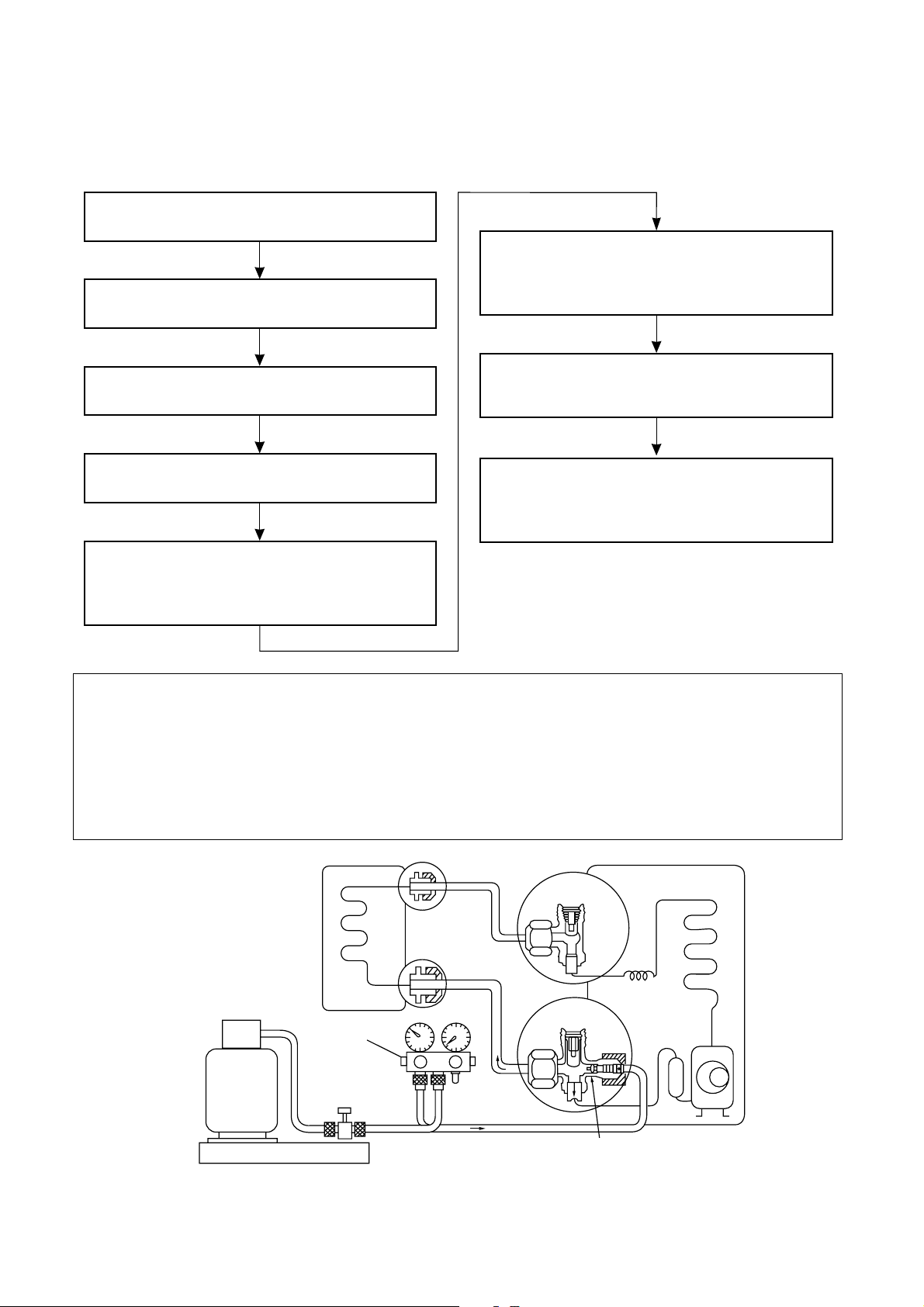
6-4. Recharging of Refrigerant
When it is necessary to recharge refrigerant, charge the specified amount of new refrigerant according to the
following steps.
Recover the refrigerant, and check no refrigerant
remains in the equipment.
When the compound gauge’s pointer has indicated -0.1 Mpa (-76 cmHg), place the handle Low
Connect the charge hose to packed valve service
port at the outdoor unit’s gas side.
in the fully closed position, and turn off the
vacuum pump’s power switch.
Connect the charge hose of the vacuum pump
adapter.
Open fully both packed valves at liquid and gas
sides.
Keep the status as it is for 1 to 2 minutes, and
ensure that the compound gauge’s pointer does
not return.
Set the refrigerant cylinder to the electronic
balance, connect the connecting hose to the
cylinder and the connecting port of the electronic
balance, and charge liquid refrigerant.
Place the handle of the gauge manifold Low in
(For refrigerant charging, see the figure below.)
the fully opened position, and turn on the vacuum
pump’s power switch. Then, evacuating the
refrigerant in the cycle.
1 Never charge refrigerant exceeding the specified amount.
2 If the specified amount of refrigerant cannot be charged, charge refrigerant bit by bit in COOL mode.
3 Do not carry out additional charging.
When additional charging is carried out if refrigerant leaks, the refrigerant composition changes in the
refrigeration cycle, that is characteristics of the air conditioner changes, refrigerant exceeding the
specified amount is charged, and working pressure in the refrigeration cycle becomes abnormally high
pressure, and may cause a rupture or personal injury.
(INDOOR unit)
Refrigerant cylinder
(With siphon pipe)
Check valve
Open/Close valve
for charging
Electronic balance for refrigerant charging
Fig. 6-4-1 Configuration of refrigerant charging
(Liquid side)
(Gas side)
– 18 –
(OUTDOOR unit)
Opened
Closed
Service port
Page 21
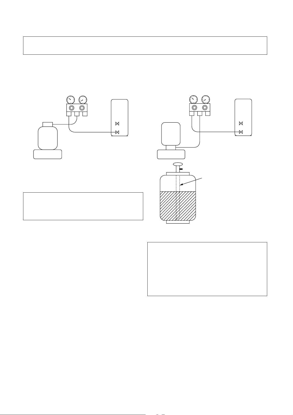
1 Be sure to make setting so that liquid can be charged.
2 When using a cylinder equipped with a siphon, liquid can be charged without turning it upside down.
It is necessary for charging refrigerant under condition of liquid because R410A is mixed type of refrigerant.
Accordingly, when charging refrigerant from the refrigerant cylinder to the equipment, charge it turning the
cylinder upside down if cylinder is not equipped with siphon.
[Cylinder with siphon][Cylinder with siphon] [Cylinder without siphon]
Gauge manifold
OUTDOOR unit
Refrigerant
cylinder
Gauge manifold
OUTDOOR unit
cylinder
Refrigerant
Electronic
balance
R410A refrigerant is HFC mixed refrigerant.
Therefore, if it is charged with gas, the composition
of the charged refrigerant changes and the
characteristics of the equipment varies.
6-5. Brazing of Pipes
6-5-1. Materials for brazing
(1) Silver brazing filler
Silver brazing filler is an alloy mainly composed of
silver and copper. It is used to join iron, copper or
copper alloy, and is relatively expensive though it
excels in solderability.
(2) Phosphor bronze brazing filler
Phosphor bronze brazing filler is generally used to
join copper or copper alloy.
(3) Low temperature brazing filler
Low temperature brazing filler is generally called
solder, and is an alloy of tin and lead. Since it is
weak in adhesive strength, do not use it for
refrigerant pipes.
Electronic
balance
Siphon
Fig. 6-4-2
1 Phosphor bronze brazing filler tends to react
with sulfur and produce a fragile compound
water solution, which may cause a gas leakage .
Therefore, use any other type of brazing filler at
a hot spring resort, etc., and coat the surface
with a paint.
2 When performing brazing again at time of
servicing, use the same type of brazing filler.
6-5-2. Flux
(1) Reason why flux is necessary
• By removing the oxide film and any foreign
matter on the metal surface, it assists the flow of
brazing filler.
• In the brazing process, it prevents the metal
surface from being oxidized.
• By reducing the brazing filler’s surface tension,
the brazing filler adheres better to the treated
metal.
– 19 –
Page 22
(2) Characteristics required for flux
• Activated temperature of flux coincides with the
brazing temperature.
• Due to a wide effective temperature range , flux
is hard to carbonize.
• It is easy to remove slag after brazing.
• The corrosive action to the treated metal and
brazing filler is minimum.
• It excels in coating performance and is harmless
to the human body.
As the flux works in a complicated manner as
described above, it is necessary to select an
adequate type of flux according to the type and
shape of treated metal, type of brazing filler and
brazing method, etc.
(3) Types of flux
• Noncorrosive flux
Generally, it is a compound of borax and boric
acid.
It is effective in case where the brazing
temperature is higher than 800°C.
• Activated flux
Most of fluxes generally used for silver brazing
are this type.
It features an increased oxide film removing
capability due to the addition of compounds
such as potassium fluoride, potassium chloride
and sodium fluoride to the borax-boric acid
compound.
(4) Piping materials for brazing and used brazing
filler/flux
6-5-3. Brazing
As brazing work requires sophisticated techniques,
experiences based upon a theoretical knowledge, it
must be performed by a person qualified.
In order to prevent the oxide film from occurring in the
pipe interior during brazing, it is effective to proceed
with brazing while letting dry Nitrogen gas (N
) flow.
2
Never use gas other than Nitrogen gas.
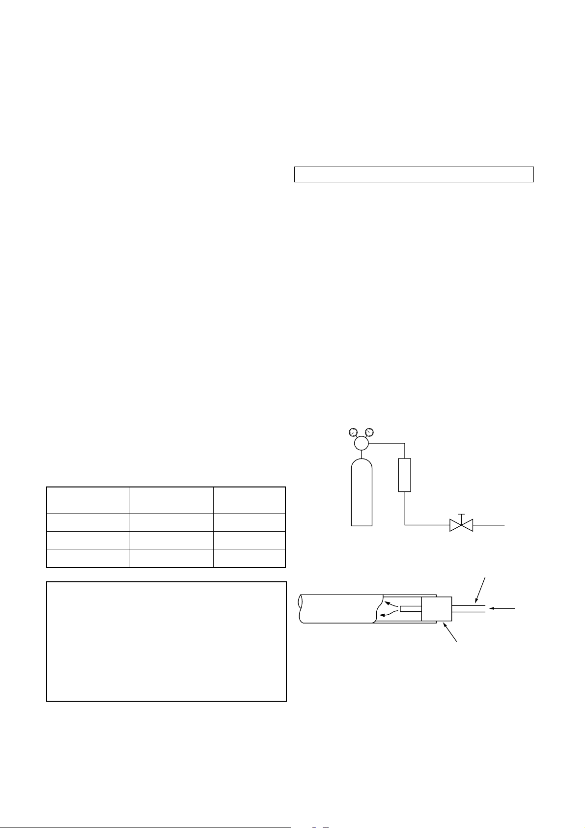
(1) Brazing method to prevent oxidation
1 Attach a reducing valve and a flow-meter to the
Nitrogen gas cylinder.
2 Use a copper pipe to direct the piping material,
and attach a flow-meter to the cylinder.
3 Apply a seal into the clearance between the
piping material and inserted copper pipe for
Nitrogen in order to prevent backflow of the
Nitrogen gas.
4 When the Nitrogen gas is flowing, be sure to
keep the piping end open.
5 Adjust the flow rate of Nitrogen gas so that it is
3
lower than 0.05 m
2
) by means of the reducing valve.
cm
/Hr or 0.02 Mpa (0.2 kgf/
6 After performing the steps above, keep the
Nitrogen gas flowing until the pipe cools down
to a certain extent (temperature at which pipes
are touchable with hands).
7 Remove the flux completely after brazing.
M
Flow meter
Piping Used brazing Used
material filler flux
Copper - Copper Phosphor copper Do not use
Copper - Iron Silver Paste flux
Iron - Iron Silver Vapor flux
1 Do not enter flux into the refrigeration cycle.
2 When chlorine contained in the flux remains
within the pipe, the lubricating oil deteriorates.
Therefore, use a flux which does not contain
chloring.
3 When adding water to the flux, use water which
does not contain chlorine (e.g. distilled water or
ion-exchange water).
4 Remove the flux after brazing.
Stop valve
Nitrogen gas
cylinder
From Nitrogen cylinder
Pipe
Nitrogen
gas
Rubber plug
Fig. 6-5-1 Prevention of oxidation during brazing
– 20 –
Page 23
Heat Exchanger Sensor (TCJ)
Heat Exchanger Sensor (TC)
Temperature Sensor
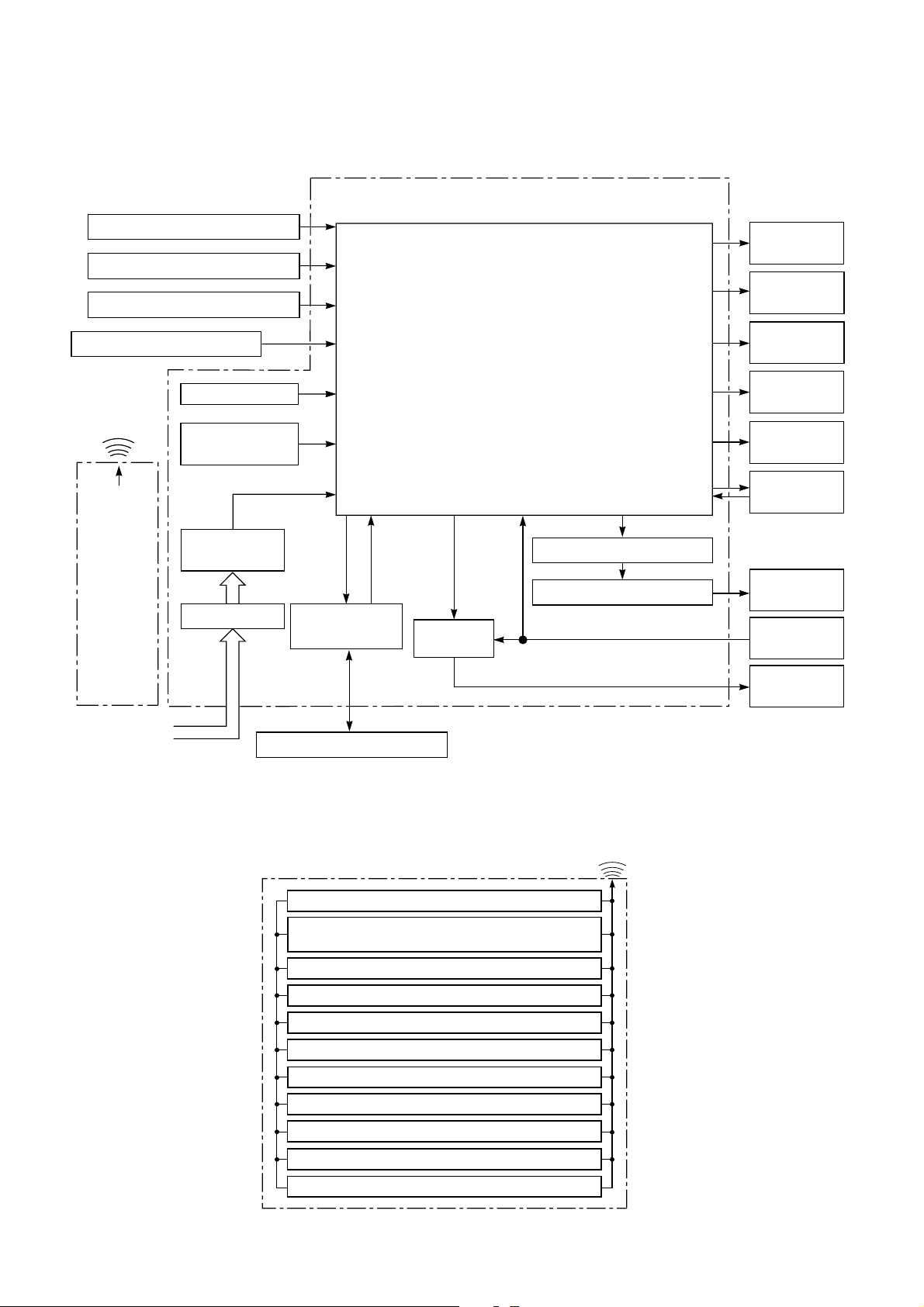
7. CONTROL BLOCK DIAGRAM
Indoor Unit Control Panel
8 MHzM.C.U.
Functions
• Louver Control
• 3-minute Delay at Restart for Compressor
Hi POWER
Display
FILTER Sign
Display
Infrared Rays Signal Receiver
Initiallizing Circuit
Infrared
Rays
36.7 kHz
Clock Frequence
Oscillator Circuit
Power Supply
Remote
Circuit
Control
Noise Filter
From Outdoor Unit
• Motor Revolution Control
• Processing
(Temperature Processing)
• Timer
• Drain Pump ON/OFF
• Serial Signal Communication
Serial Signal
Transmitter/
Receiver
Serial Signal Communication
Relay
RY401
Louver ON/OFF Signal
Louver Driver
PRE DEF.
Sign Display
TIMER
Display
OPERATION
Display
Indoor Fan
Motor
Louver Motor
Float
Switch
Drain
Pump
REMOTE CONTROL
Infrared Rays
Remote Control
Operation (START/STOP)
Operation Mode Selection
AUTO, COOL, DRY, HEAT, FAN ONLY
Temperature Setting
Fan Speed Selection
ON TIMER Setting
OFF TIMER Setting
Louver Auto Swing
Louver Direction Setting
ECO
Hi power
Filter Reset
– 21 –
Page 24
8. OPERATION DESCRIPTION
8-1.When power supply is reset
(1) Distinction of outdoor units
When the power supply is reset, the outdoors are
distinguished, and control is exchanged according
to the distinguished result.
(2) Setting of the indoor fan speed
Based on EEPROM data, rspeed of the indoor fan
is selected.
Remarks: Air speed
8-2.Operation mode selection
(1) Based on the operation mode selecting command
from the remote control, the operation mode is
selected.
Table 8-2-1
Remote control
command
STOP Air conditioner stops.
FAN Fan operation
COOL Cooling operation
DRY Dry operation
HEAT Heating operation
AUTO Automatic operation
(2) Automatic Operation
• The air conditioner selects and operates in one
of the operating modes of cooling, heating or
fan only, depending on the room temperature.
• If the AUTO mode is uncomfortable, you can
select the desired conditions manually.
Outline of control
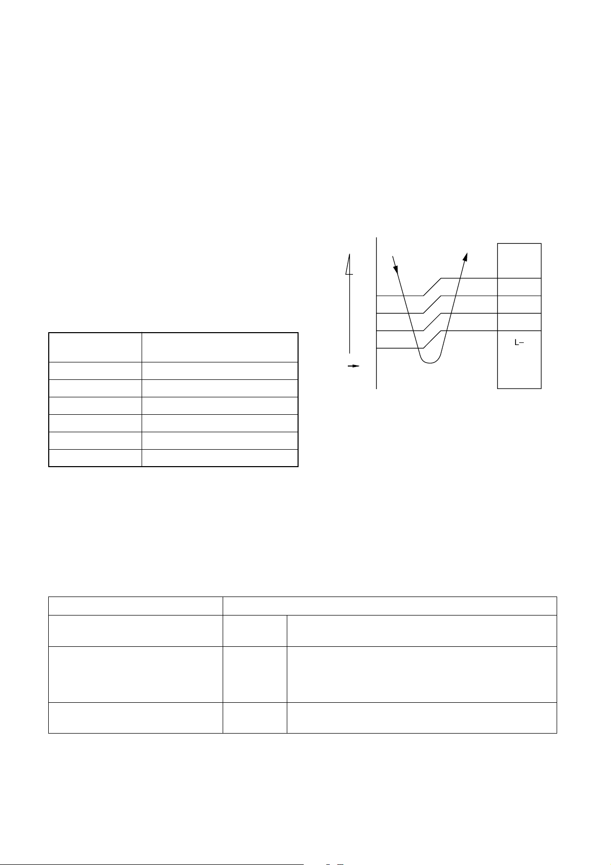
8-3.Air volume control
(1) Operation with [HIGH (H)], [MED (M)], [LOW (L)],
or [AUTO] mode is performed by the command
from the remote control.
(2) When [FAN] button is set to AUTO, the indoor fan
motor operates as shown in Fig. 8-3-1, Fig. 8-3-2
and Table 8-3-1.
<COOL>
°C
+3
+2.5
+2
+1.5
+1
+0.5
(Room temp.) − (Preset temp.)
Preset
temp.
0
−0.5
NOTE :
*1: The values marked with *1 are calculated and
controlled by the difference in motor speed
between M+ and L–.
Fig. 8-3-1
M+
*1
*1
*1
Table 8-2-2
Room temperature in operation Operating condition
The set temperature +1°C or higher
(in case that the room is hot)
The set temperature –1°C to +1°C
Cooling
operation
Fan only
operation
Performs the cooling operation at a temperature 1°C
higher than the setting.
Performs the fan only operation (low speed) while
monitoring the room temperature. When the room
temperature changes, the air conditioner will select the
cooling or heating mode.
The set temperature –1°C or lower
(in case that the room is cold)
Heating
operation
Performs the heating operation at a temperature 1°C
lower than the setting.
– 22 –
Page 25
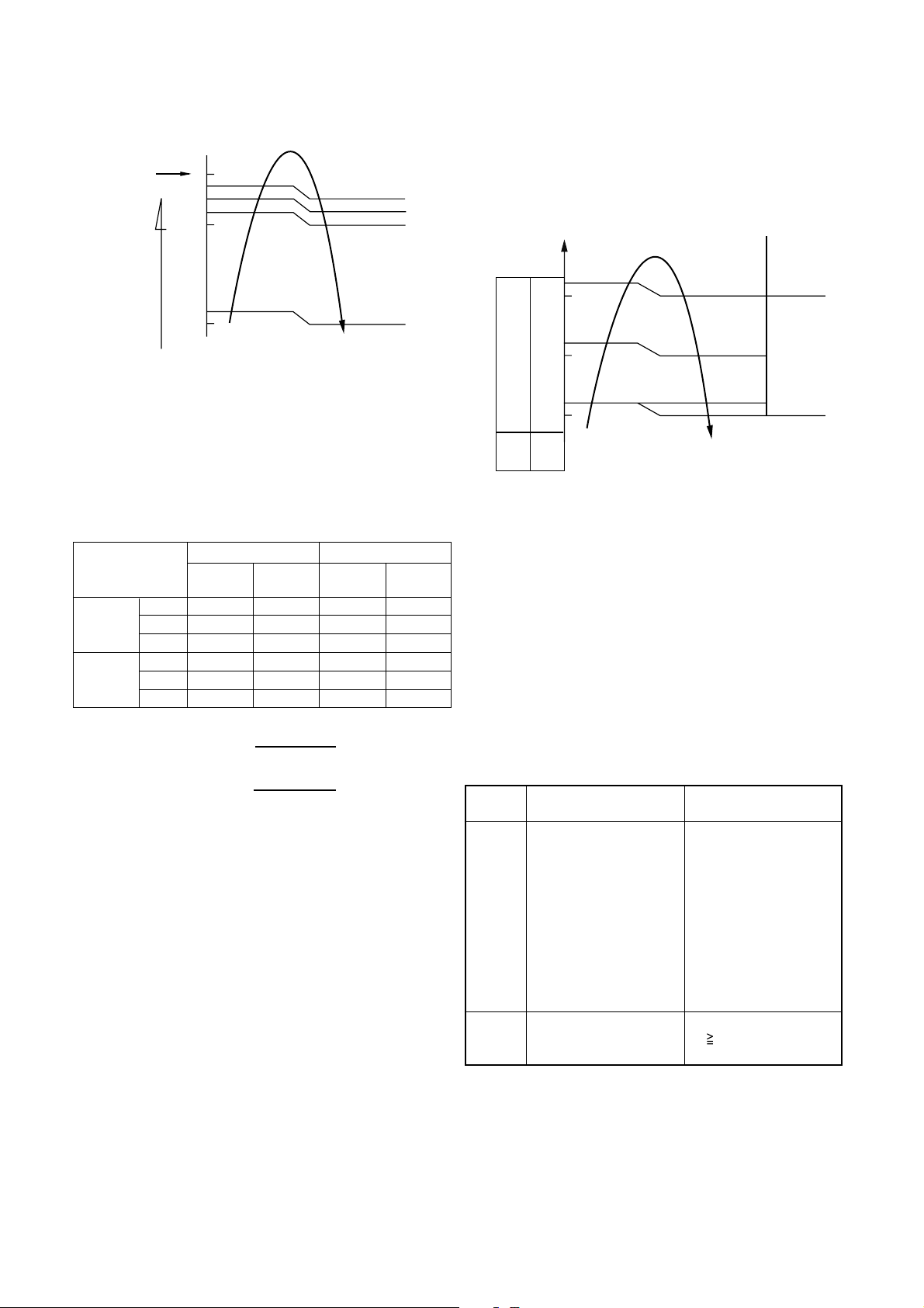
<HEAT>
8-4.Cool air discharge preventive control
Preset
temp.
°C
0
−0.5
−1
−1.5
−2
−5.0
−5.5
[FAN AUTO]
(Room temp.) − (Preset temp.)
L
*1
*2
+
M
H
NOTE :
*1, *2 : The values marked with *1 and *2 are
calculated and controlled by the difference in
motor speed between M+ and L.
Fig. 8-3-2
Table 8-3-1
RAV-SM560XT-E RAV-SM800XT-E
MODEL
Cooling HIGH 1060 800 1190 900
and MED 950 690 1010 750
Fan only LOW 800 580 850 650
Heating MED 970 730 1070 800
Motor speed Air flow level Motor speed Air flow level
(rpm) (m3/h) (rpm) (m3/h)
HIGH 1120 830 1300 980
LOW 820 600 860 650
In heating operation, the indoor heat exchanger
restricts revolving speed of the fan motor to prevent a
cold draft. The upper limit of the revolving speed is
shown in Fig. 8-4-1 and Table 8-4-1.
Manual
(One of
AUTO
*4
SUL*
SUL*1
Stop
5 steps)
L−H
(Up to
setting
3
speed)
*2
A+4 A+4
A−8A−8
464534
33
33 21
32 20
*6 *5
NOTES :
*1: The fan stops for 2 minutes after thermostat-OFF.
*2: A is 24°C when the preset temperature is 24°C or
more and A is the preset temperature when it is
under 24°C.
*3: SUL means Super Ultra Low.
*4: Calculated from difference in motor speed
between SUL and HIGH.
Fig. 8-4-1 Cold draft preventing control
LOW
MED
LOW+MED
+
=
MED+HIGH
+
=
*5 and *6:
2
2
Fan *5 *6
speed Starting period Stabilized period
AUTO • Up until 12 minutes
passed after starting
the unit
• From 12 to 25 minutes
passed after starting
the unit and room
temperature is 3°C
lower than preset
temperature
Manual • Room temperature
(L – H) < Preset temperature
Table 8-4-1
–4°C
• From 12 to 25 minutes
passed after starting
the unit and room
temperature is
between preset
temperature and 3°C
lower than preset
temperature
• 25 minutes or more
passed after starting
the unit
• Room temperature
Preset temperature
–3.5°C
– 23 –
Page 26
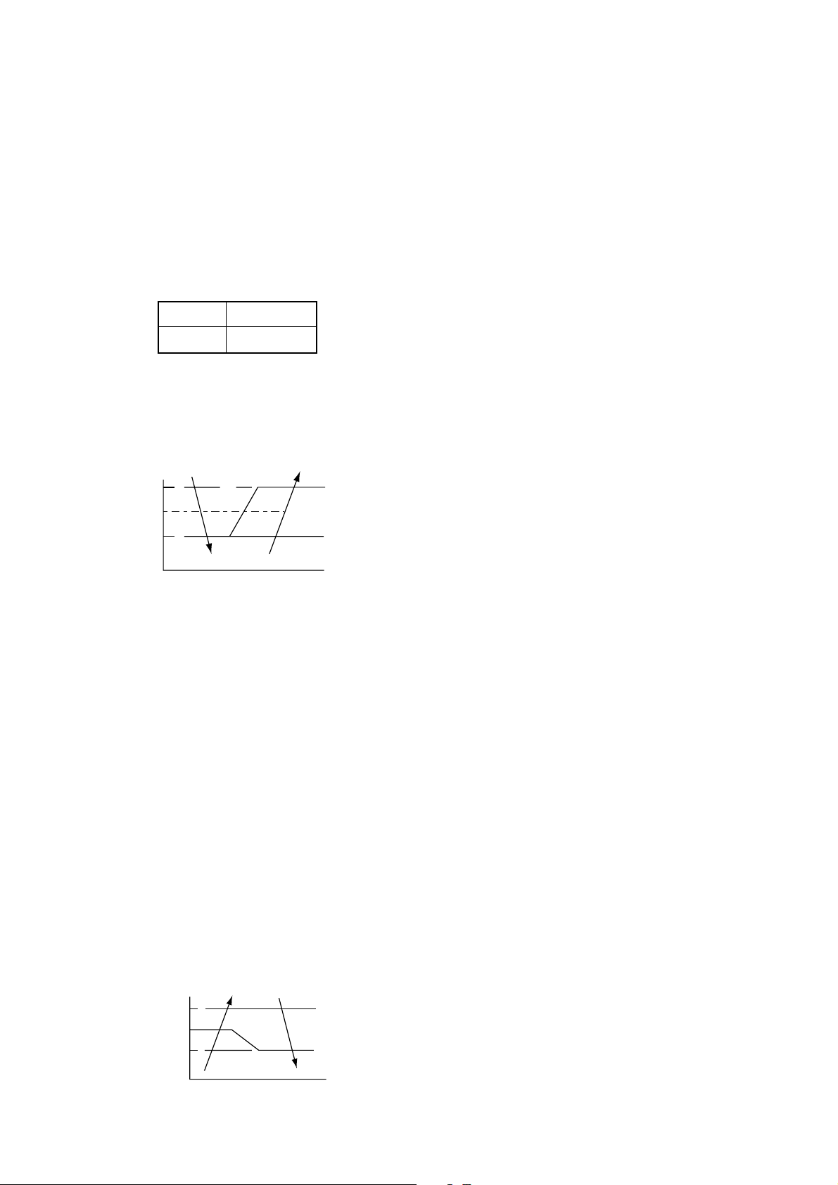
8-5.Freeze preventive control (Low
temperature release)
The cooling operation (including Dry operation) is
performed as follows based on the detected
temperature of Tc sensor or Tcj sensor.
When [J] zone is detected for T1 minutes (Following
figure), the commanded frequency is decreased from
the real operation frequency. After then the
commanded frequency changes every 2 minutes while
operation is performed in [J] zone.
T1
Normal 1 minute
In [K] zone, time counting is interrupted and the
operation is held.
When [I] zone is detected, the timer is cleared and the
operation returns to the normal operation.
(°C)
7
6
5
In heating operation, the freeze-preventive control
works if 4-way valve is not exchanged and the
condition is satisfied.
I
J
Fig. 8-5-1
A
K
8-7.Louver control
(1) Vertical air flow louver
Position of veritcal air flow louver is automatically
controlled according to the operation mode.
Besides, position of vertical air flow louver can be
arbitrarily set by pressing [FIX] button.
The louver position which is set by [FIX] button is
stored in the microcomputer, and the louver is
automatically set at the stored position for the next
operation.
(2) Swing
If [SWING] button is pressed when the indoor unit
is in operation, the vertical air flow louver starts
swinging. When [SWING] button is pressed, it
stops swinging.
8-8.Filter sign display
(1) The operation time of the indoor fan is calculated,
the filter lamp (Orange) on the display part of the
main unit goes on when the specified time (240H)
has passed. When a wired remote controller is
connected, the filter reset signal is sent to the
remote controller, and also it is displayed on LCD
of the wired remote control.
(2) When the filter reset signal has been received
from the wired remote control after [FILTER] lamp
has gone on or when the filter check button
(Temporary button) is pushed, time of the
calculation timer is cleared. In this case, the
measurement time is reset if the specified time
has passed, and display on LCD and the display
on the main unit disappear.
Remarks:
Tcj : Indoor heat exchanger sensor temperature
8-6.High-temp release control
The heating operation is performed as follows based
on the detected temperature of Tc sensor.
• When [M] zone is detected, the commanded
frequency is decreased from the real operation
frequency. After then the commanded frequency
changes every 30 seconds while operation is
performed in [M] zone.
• In [N] zone, the commanded frequency is held.
• When [L] zone is detected, the commanded
frequency is returned to the original value by
approx. 6Hz every 60 seconds.
Tc (°C)
55 A
52
48 B
L
M
N
Remarks:
[FILTER] goes on
Fig. 8-6-1
– 24 –
Page 27
8-9.Auto Restart Function
PRE.DFILTERHi POWER
PRE.DFILTERHi POWER
The indoor unit is equipped with an automatic
restarting function which allows the unit to restart
operating with the set operating conditions in the event
of power supply being accidentally shut down. The
operation will resume without warning three minutes
after power is restored.
This function is not set to work when shipped from the
factory. Therefore it is necessary to set it to work.
8-9-1. How to set auto restart function
To set the auto restart function, proceed as follows:
The power supply to the unit must be on; the function
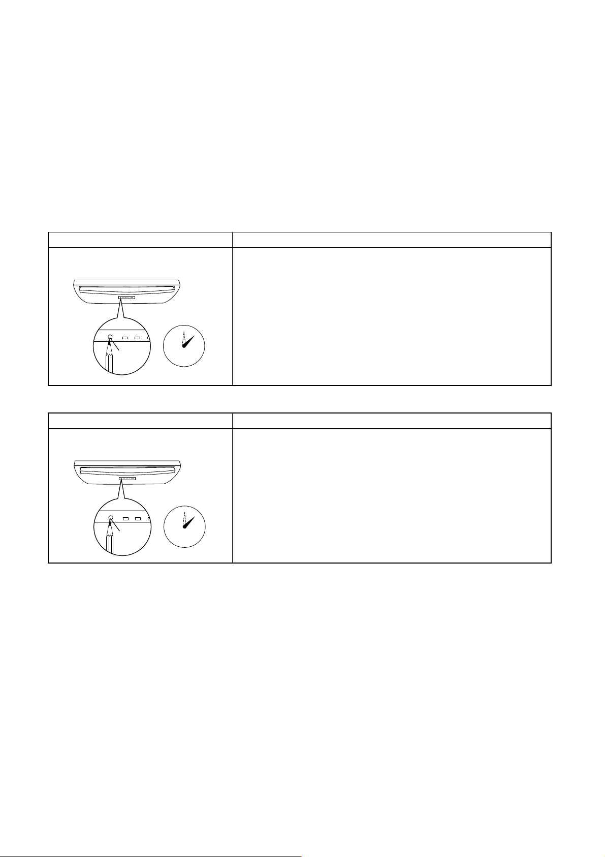
will not set if the power is off.
Push the [TEMPORARY] button located in the center
of the front panel continuously for three seconds.
The unit receives the signal and beeps three times.
The unit then restarts operating automatically in the
event of power supply being accidentally shut down.
When the unit is on standby (Not operating)
Operation Motions
Push [TEMPORARY] button for more The unit is on standby.
than three seconds.
→
The unit starts to operate. The green lamp is on.
→
After approx. three seconds,
0
3S
The unit beeps three times The lamp changes from
and continues to operate. green to orange.
TEMPORARY
button
If the unit is not required to operate at this time, push [TEMPORARY]
button once more or use the remote control to turn it off.
When the unit is in operation
Operation Motions
Push [TEMPORARY] button for more The unit is in operation. The green lamp is on.
than three seconds.
The unit stops operating. The green lamp is turned off.
→
→
After approx. three seconds,
0
3S
TEMPORARY
button
• While this function is being set, if the unit is in
operation, the orange lamp is on.
• This function can not be set if the timer operation
The unit beeps three times.
If the unit is required to operate at this time, push [TEMPORARY]
button once more or use the remote control to turn it on.
• While the filter check lamp is on, the
TEMPORARY button has the function of filter
reset button.
has been selected.
• When the unit is turned on by this function, the
louver will not swing even though it was swinging
automatically before shutting down.
– 25 –
Page 28

8-9-2. How to cancel auto restart function
PRE.DFILTERHi POWER
PRE.DFILTERHi POWER
To cancel auto restart function, proceed as follows:
Repeat the setting prodedure: the unit receives the
signal and beeps three times.
The unit will be required to be turned on with the
remote control after the main power supply is turned
off.
When the unit is on standby (Not operating)
Operation Motions
Push [TEMPORARY] button for more The unit is on standby.
than three seconds.
→
The unit starts to operate. The orange lamp is on.
→
After approx. three seconds,
0
3S
The unit beeps three times The lamp changes from
and continues to operate. orange to green.
TEMPORARY
button
If the unit is not required to operate at this time, push [TEMPORARY]
button once more or use the remote control to turn it off.
When the unit is in operation
Operation Motions
Push [TEMPORARY] button for more The unit is in operation. The orange lamp is on.
than three seconds.
The unit stops operating. The orange lamp is turned off.
→
→
After approx. three seconds,
0
3S
TEMPORARY
button
• While this function is being set, if the unit is in
operation, the orange lamp is on.
8-9-3. Power failure during timer operation
The unit beeps three times.
If the unit is required to operate at this time, push [TEMPORARY]
button once more or use the remote control to turn it on.
8-10. Filter Check Lamp
When the elapsed time reaches 1000 hours, the filter
check lamp indicates. After cleaning the filters, turn off
the filter check lamp.
When the unit is in Timer operation, if it is turned off
because of power failure, the timer operation is
8-10-1. How to turn off filter check lamp
cancelled. Therefore, set the timer operation again.
(1) Press [FILTER] button on the remote control.
(2) Push [TEMPORARY] button on the indoor unit.
Note:
If [TEMPORARY] button is pushed while the filter
check lamp is not indicating, the indoor unit will start
the Automatic Operation.
– 26 –
Page 29

9. INSTALLATION PROCEDURE
Remark per EMC Directive 89/336/EEC
To prevent flicker impressions during the start of the compressor (technical process) following installation
conditions do apply.
1. The power connection for the air conditioner has to be done at the main power distribution. This distribution
has to be of an impedance.
Normally the required impedance is reached at a 32A fusing point. Air conditioner fuse has to be 16A max.!
2. No other equipment should be connected to this power line.
3. For detailed installation acceptance, please contact your power supplier whether its restriction does apply
for products like washing machines, air conditioners or electrical ovens.
4. For power details of the air conditioner, refer to the rating plate of the product.
9-1.Installation Diagram of Indoor and Outdoor Units
(Under Ceiling Installation)
200 mm or more
Pipe shield
e
r
o
rm
o
m
m
0
0
2
7 Zeolite filter
Air filter
Before install the wireless
remote controller
• With the remote controller cover
open, load the batteries supplied
correctly, observing their polarity.
%%
% Wireless remote controller
%%
Cover
70 m
m or m
ore
9 Filter frame
8 Purifying filter
% Wireless remote controller
(Console Installation)
1 Installation plate
200 m
or m
m
ore
# Pan head wood screw
" Remote controller holder
Hook
4 Mounting
200 m
or m
m
ore
re
o
or m
m
m
70
Insulate the refrigerant pipes
separately with insulation, not
together.
screw
!!
! Batteries
!!
Min 6 mm thick heat resisting
polyethylene foam
– 27 –
Page 30

9-2.PRECAUTIONS FOR SAFETY
• Ensure that all Local, National and International regulations are satisfied.
• Read this “PRECAUTIONS FOR SAFETY” carefully before Installation.
• The precautions described below include the important items regarding safety. Observe them without fail.
• After the installation work, perform a trial operation to check for any problem.
Follow the Owner’s Manual to explain how to use and maintain the unit to the customer.
• Turn off the main power supply switch (or breaker) before the unit maintenance.
• Ask the customer to keep the Installation Manual together with the Owner’s Manual.
CAUTION
New Refrigerant Air Conditioner Installation
• This air conditioner adopts the new HFC refrigerant (R410A) which does not destroy ozone layer.
The characteristics of R410A refrigerant are ; easy to absorb water, oxidizing membrane or oil, and its
pressure is approx. 1.6 times higher than that of refrigerant R22. Accompanied with the new refrigerant,
refrigerating oil has also been changed. Therefore, during installation work, be sure that water, dust, former
refrigerant, or refrigerating oil does not enter the refrigerating cycle.
To prevent charging an incorrect refrigerant and refrigerating oil, the sizes of connecting sections of charging
port of the main unit and installation tools are charged from those for the conventional refrigerant.
Accordingly the exclusive tools are required for the new refrigerant (R410A).
For connecting pipes, use new and clean piping designed for R410A, and please care so that water or dust
does not enter. Moreover, do not use the existing piping because there are problems with pressure-resistance
force and impurity in it.
CAUTION
This appliance must be connected to the main power supply by means of a switch with a contact separation
of at least 3 mm.
The installation fuse (25A D type
To Disconnect the Appliance from Main Power Supply
) must be used for the power supply line of this conditioner.
WARNING
• Ask an authorized dealer or qualified installation professional to install/maintain the air conditioner.
Inappropriate installation may result in water leakage, electric shock or fire.
• Turn off the main power supply switch or breaker before attempting any electrical work.
Make sure all power switches are off. Failure to do so may cause electric shock.
• Connect the connecting cable correctly.
If the connecting cable is connected in a wrong way, electric parts may be damaged.
• When moving the air conditioner for the installation into another place, be very careful not to enter
any gaseous matter other than the specified refrigerant into the refrigeration cycle.
If air or any other gas is mixed in the refrigerant, the gas pressure in the refrigeration cycle becomes
abnormally high and it may resultingly causes pipe burst and injuries on persons.
• Do not modify this unit by removing any of the safety guards or by by-passing any of the safety
interlock switches.
• Exposure of unit to water or other moisture before installation may cause a short-circuit of electrical
parts.
Do not store it in a wet basement or expose to rain or water.
– 28 –
Page 31

• After unpacking the unit, examine it carefully if there are possible damage.
• Do not install in a place that might increase the vibration of the unit.
• To avoid personal injury (with sharp edges), be careful when handling parts.
• Perform installation work properly according to the Installation Manual.
Inappropriate installation may result in water leakage, electric shock or fire.
• When the air conditioner is installed in a small room, provide appropriate measures to ensure that
the concentration of refrigerant leakage occur in the room does not exceed the critical level.
• Install the air conditioner securely in a location where the base can sustain the weight adequately.
• Perform the specified installation work to guard against an earthquake.
If the air conditioner is not installed appropriately, accidents may occur due to the falling unit.
• If refrigerant gas has leaked during the installation work, ventilate the room immediately.
If the leaked refrigerant gas comes in contact with fire, noxious gas may generate.
• After the installation work, confirm that refrigerant gas does not leak.
If refrigerant gas leaks into the room and flows near a fire source, such as a cooking range,
noxious gas might generate.
• Electrical work must be performed by a qualified electrician in accordance with the Installation
Manual. Make sure the air conditioner uses an exclusive power supply.
An insufficient power supply capacity or inappropriate installation may cause fire.
• Use the specified cables for wiring connect the terminals securely fix. To prevent external forces
applied to the terminals from affecting the terminals.
• Be sure to provide grounding.
Do not connect ground wires to gas pipes, water pipes, lightning rods or ground wires for telephone cables.
• Conform to the regulations of the local electric company when wiring the power supply.
Inappropriate grounding may cause electric shock.
• Do not install the air conditioner in a location subject to a risk of exposure to a combustible gas.
If a combustible gas leaks, and stays around the unit, a fire may occur.
– 29 –
Page 32

9-3.Accessory parts and Parts to be procured locally
9-3-1. Accessor y parts
Part
No
1
2
3
4
5
6
Part name Q’ty Shape
Installation plate 1
Installation Manual 1
Owner’s Manual 1
Mounting screw
∅4 x 25 S
Flexible pipe 1
Drain nipple
(Packaged with the 1
outdoor unit)
Part
No
8
9
!
"
8
#
$
%
Part name Q’ty Shape
Purifying filter 1
Filter frame 2
Battery 2
Remote controller
holder
Pan head wood
screw ∅3.1 x 16 S
Pipe shield 1
Wireless remote
controller
1
2
1
Zeolite filter 1
7
9-3-2. Parts to be procured locally
Connecting pipe (Liquid side)
(6.35 mm (diam.), Nominal (diam.) 1/4" thick 0.8 mm)
RAV-SM560XT-E, RAV-SM560AT-E
(9.52 mm (diam.), Nominal (diam.) 3/8" thick 0.8 mm)
RAV-SM800XT-E, RAV-SM800AT-E
Connecting pipe (Gas side)
(12.7 mm (diam.), Nominal (diam.) 1/2" thick 0.8 mm)
RAV-SM560XT-E, RAV-SM560AT-E
(15.9 mm (diam.), Nominal (diam.) 5/8" thick 1.0 mm)
RAV-SM800XT-E, RAV-SM800AT-E
Power supply cord
2
2.5 mm
(H07RN-F or 245IEC66) or 3.5 mm2 (AWG-12)
Connecting cable
H07RN-F or 245IEC66 (1.5 mm
Thermal insulation for refrigerant pipe
(10 mm or more, thermal insulating foam polyethylene)
Thermal insulation for drain pipe
(10 mm or more, foam polyethylene)
Drain pipe (Outer 26 mm (diam.))
Tapes
Grounding cable (2.0 mm (diam.) or more)
2
or more)
– 30 –
Page 33

9-4.SELECTION OF INSTALLATION PLACE
W ARNING
• Install the air conditioner where there is sufficient strength to withstand the weight of the unit.
If the strength is not sufficient, the unit may fall down resulting in injury.
CAUTION
Upon approval of the customer, install the air conditioner in a place that satisfies the following
conditions.
• Place where the unit can be installed horizontally.
• Place where a sufficient servicing space can be ensured for safe maintenance and check.
• Place where drained water will not cause any problem.
Avoid installing in the following places.
• Place exposed to air with high salt content (seaside area), or place exposed to large quantities of sulfide
gas (hot spring). (Should the unit be used in these places, special protective measures are needed.)
• Place exposed to oil, vapor, oil smoke or corrosive gas.
• Place where organic solvent is used nearby.
• Place close to a machine generating high frequency.
• Place where noise of the outdoor unit is easy to transmit.
(When installing the air conditioner on the boundary with the neighbor, pay due attention to the level of
noise.)
• Place with poor ventilation.
• Where the ceiling height is more than 3 m.
• Where the floor/wall/ceiling structure is unable to support the weight of the unit.
9-5.INSTALLATION OF INDOOR UNIT
WARNING
• Install the air conditioner certainly at a place to sufficiently withstand the weight.
If the strength is insufficient, the unit may fall down resulting in human injury.
• Perform a specified installation work to guard against an earthquake.
An incomplete installation can cause accidents by the units falling and dropping.
Locate the unit so as to provide uniform circulation of chilled air.
Avoid locating the unit as shown in the bad-marked figures below:
Good location
Evenly hot or cooled
Shaded area well hot or cooled
Bad location
Shaded area well hot or cooled
If a good location is not possible, use a fan to circulate the air evenly throughout the room.
Bad location
– 31 –
Page 34

9-5-1. Installation Place
• A place which provides the spaces around the
indoor unit as shown in the above diagram.
• A place where there is no obstacle near the air inlet
and outlet.
• A place that allows easy installation of the piping to
the outdoor unit.
• A place which allows the Front panel to be opened.
CAUTION
• Direct sunlight or fluorescent light to the indoor
unit’s wireless receiver should be avoided.
• The microprocessor in the indoor unit should not
be too close to RF noise sources.
(For details, see the owner’s manual.)
<Remote controller>
• A place where there are no obstacles such as a
curtain that may block the signal from the indoor unit.
• Do not install the remote controller in a place
exposed to direct sunlight or close to a heating
source, such as a stove.
• Keep the remote controller at least 1 m apart from
the nearest TV set or stereo equipment. (This is
necessary to prevent image disturbances or noise
interference.)
• The location of the remote controller should be
determined as shown below.
<Remote controller usage>
• Under Ceiling Installation
Ceiling
7 m
Wall
Remote controller
Reception range
Reception
range
Fig. 9-5-1
5 m
5 m
Remote
controller
9-5-2. Before Installation
<Remove the Air inlet grille>
1. Open the Air inlet grille by both hands.
2. Loosen three screws for fixing the Panel arm. Do
not remove the screws at this time.
1
2
1
Screw
2
Fig. 9-5-3
3. First, move the Air inlet grille upward, then turn it
backwards.
4. Remove the Grille stopper from the axis of the Front
panel. After that, remove the Air inlet grille.
5. Remove the Panel arms from the Front panel.
Grille stopper
3
3
Panel arm
5
Fig. 9-5-4
9-5-3. After Installation
<Install the Air inlet grille>
1. Insert the three Panel Arms on the Air inlet grille
and fix each securely by screws.
*7 m
Panel arm
Panel arm
• Console Installation
7 m
5 m
Reception
range
5 m
Remote
controller
Wall
Reception
range
Floor
Remote controller
* Axial distance
Fig. 9-5-2
NOTICE
The Paper pattern is inside the package box cover.
Do not bend and dispose of it before installing.
*7 m
– 32 –
Fig. 9-5-5
CAUTION
• The screws that fixed with Panel Arms must not
be loose.
Page 35

2. Set the Air inlet grille arm to the axis of the Front
panel.
3. Insert the Grille stopper to the correct position and
fix it securely with screws.
4. Push the Air inlet grille to the correct position.
Axis of the
Air inlet
grille arm
Front panel
<Install the indoor unit>
1. Remove the Side covers and the Installation plate
1.
2. Insert the Suspension bolts into the metal fittings of
the indoor unit.
3. Set to nuts, spring washers and washers on both
sides of the metal fittings and then move the indoor
unit backward.
4. Secure it with the M10 Nuts. (4 pcs.)
5. Attach the Side covers to the unit.
Rib
Fig. 9-5-6
9-5-4. Under Ceiling Installation
For the installation of the indoor unit use the Paper
pattern, which is inside the package box cover.
<Install the Suspension bolts>
• Install the Suspension bolts so that it can support
the indoor unit.
240 mm or more
1093
1015
330
60
140
Fig. 9-5-7
235 mm
or more
11
1 Installation plate
Suspension bolt
Side cover
3
2
4
Nut (M10)
11
Suspension bolt
Side cover
Fig. 9-5-9
<Condition for Installation>
• The unit must not decline more than 15 mm in either
axis.
15 mm
15 mm
• Adjust distance to ceiling before installation.
25~30 mm
40~45 mm
Suspension
bolt
Washer
Spring
washer
Nut (M10)
Spring
washer
Washer
Nut (M10)
Fig. 9-5-8
Suspension
bolt (M10)
Fig. 9-5-10
<Piping and Drain Hose Installation>
• The piping direction can be 4 ways as illustrated.
• The Drain hose is only one way.
Upper piping
Rear upper piping
Side piping
Rear piping Drain hose
Fig. 9-5-11
– 33 –
Page 36

• How to install the Drain hose.
1. Remove the two screws and the Drain band.
2. Cut a slit for the drain hose hole.
Slit for drain hose hole
Drain band
• Other direction piping.
1. Cut the slit of connecting only upper direction.
Slit for upper piping
Cover for rear
upper piping
Cover for side piping
Drain hose
Screws
Fig. 9-5-12
3. Place the Drain hose on the U-shape space and
secure it with the Drain band and two screws.
Fig. 9-5-13
• Rear side piping with Drain hose. (Recommended
direction)
Ceiling
175 mm
or more
Rear piping hole ∅80
Fig. 9-5-16
2. Connect the Flexible pipe 5 to the large pipe
(Gas side).
Big pipe
55
5 Flexible pipe
55
Fig. 9-5-17
140 mm
Ceiling
Wall
Fig. 9-5-14
1. Cut or remove the determined direction slit or cover.
2. Pipes and the Drain hose should be fixed together
by the Drain band with two screws.
Cut
Fig. 9-5-15
– 34 –
Page 37

9-5-5. Console Installation
• Select the terminal of Selector-SW from [C position]
to [F position].
B
F
INSTALL
REMOCON
A
C
Fig. 9-5-18
<Cutting a hole and mounting the Installation plate>
• When installing the rear piping, determine the pipe
hole position, drill the pipe hole (∅80 mm) at a slight
downward slant to the outdoor side.
• For mounting of the Installation plate 1, use the
Paper pattern, which is inside the package box cover.
1093
742
375 mm
or more
<Install the indoor unit>
• Install the Installation plate 1 at the wall according
to the Paper pattern.
• Hang the indoor unit on the hooks of the Installation
plate 1.
• Fix the lower portion of the indoor unit with Mounting
screws 4 (2 places).
Indoor unit
Hook
11
1 Installation
11
plate
44
4 Mounting screw
44
160
390 mm
or more
320
Floor
140
Rear piping hole ∅80
633
60
Fig. 9-5-19
Anchor bolt
Projection
15 mm or less
5 mm dia. hole
44
4 Mounting screw
44
Clip anchor
(local parts)
∅4 x 25
ss
s
ss
Fig. 9-5-20
CAUTION
Failure to firmly install the unit may result in personal
injury and property damage if the unit falls .
• In case of block, brick, concrete or similar type walls,
make 5 mm dia. holes in the wall.
• Insert clip anchors for appropriate Mounting screws
4.
NOTE :
• Secure four corners and lower parts of the
Installation plate 1 with 6 to 8 mounting screws to
install it.
44
4 Mounting screw
44
Fig. 9-5-21
<Condition for installation>
• The unit must not decline more than 15 mm in either
axis.
15 mm
Fig. 9-5-22
<Piping and Drain Hose Installation>
• The piping direction can
be the following 3 ways
with the Drain hose.
• Each piping direction
should be connected with
the Flexible pipe 5.
Side piping
Bottom piping
Fig. 9-5-22
• Cut or remove the
determined direction
slit or cover.
Cover for
side piping
– 35 –
Cover for rear
upper piping
Fig. 9-5-23
Rear piping
Slit for upper
piping
Page 38

9-6.DRAIN PIPING WORK
9-6-1. Drainage
1. Run the Drain hose sloping downward.
NOTE :
• The hole should be made at a slight downward slant on the outdoor side.
Under Ceiling Installation
Console Installation
50 mm or more
50 mm or more
Fig. 9-6-1
NOTICE
In case of upward drainage from the unit, (Under Ceiling Installation), it is necessary to use the Drain pump
kit of optional part.
CAUTION
1. Do not raise the Drain hose.
2. Do not put the Drain hose into water.
3. Do not form the Drain hose into a wave shape.
4. Do not put the Drain hose end in the drainage ditch.
2. Open the louver manually and put some water into it.
Then check the flow of water from the Drain hose.
Fig. 9-6-2
3. When connecting the Extension drain hose; insulate the connecting part of Extension drain hose with the
Pipe shield.
Pipe shield
Drain hose
Inside the room
Extension drain hose
Fig. 9-6-3
CAUTION
Arrange the drain pipe for proper drainage from the unit.
Improper drainage can result in dew-dropping. (Provide by customer)
– 36 –
Page 39

9-7.REFRIGERANT PIPING
9-7-1. Refrigerant Piping
1. If the outdoor units are to be mounted on a wall, make sure that the platform supporting is sufficiently strong.
The platform should be designed and manufactured to maintain its strength over a long period of time, and
sufficient consideration should be given to ensuring that the outdoor unit will not fall.
2. Use copper pipe with 0.8 mm or more thickness.
3. Flare nut and flare works are also different from those of the conventional refrigerant. Take out the flare nut
attached to the main unit of the air conditioner, and use it.
CAUTION
IMPORTANT 4 POINTS FOR PIPING WORK
1. Take away dust and moisture from the inside of the connecting pipes.
2. Tight connection (between pipes and unit)
3. Evacuate the air in the connecting pipes using VACUUM PUMP.
4. Check the gas leakage. (Connected points)
9-7-2. Permissible Piping Length and Head
The maximum piping length from the outdoor to indoor unit The maximum height difference outdoor/indoor unit
30 m (Without charge 20 m) 50 m (Without charge 20 m)
(RAV-SM560AT-E) (RAV-SM800AT-E)
Outdoor unit is above Outdoor unit is below
30 m 15 m
<Flaring>
Insert a flare nut into the pipe, and flare the pipe.
As the flaring sizes of R410A differ from those of refrigerant R22, the flare tools
newly manufactured for R410A are recommended.
However, the conventional tools can be used by adjusting projection margin of
the copper pipe.
• Projection margin in flaring : B (Unit : mm)
Rigid (Clutch type) Imperial (Wing nut type)
Outer diam.
of copper pipe
6.35/9.52
12.7/15.9
R410A tool used
R410A R22
0 to 0.5 (Same as left)
0 to 0.5 (Same as left)
Conventional tools used
R410A R22
1.0 to 1.5 0.5 to 1.0
1.0 to 1.5 0.5 to 1.0
• Flaring dia meter size : A (Unit : mm)
Outer diam. of copper pipe
6.35 9.1 9.0
12.7/15.9 16.6 16.2
R410A R22
A
+0
–0.4
Outer diam. of copper pipe R410A R22
6.35/9.52 1.5 to 2.0 1.0 to 1.5
12.7/15.9 2.0 to 2.5 1.5 to 2.0
* In the case of the flaring for R410A with the
conventional flare tool, pull out it approx. 0.5 mm
more than that for R22 to adjust to the specified
flare size.
The copper pipe gauge is useful for adjusting
projection margin size.
B
Fig. 9-7-1
A
– 37 –
Fig. 9-7-2
Page 40

<Tightening connection>
Align the centers of the connecting pipes and tighten
the flare nut as far as possible with your fingers. Then
tighten the nut with a spanner and torque wrench as
shown in the figure.
CAUTION
• Do not apply excess torque. Otherwise, the nut
may crack depending on the conditions.
(Unit : N•m)
Outer diam. of copper pipe Tightening torque
6.35 mm (diam.) 14 to 18 (1.4 to 1.8 kgf•m)
9.52 mm (diam.) 33 to 42 (3.3 to 4.2 kgf•m)
12.7 mm (diam.) 50 to 62 (5.0 to 6.2 kgf•m)
15.9 mm (diam.) 63 to 77 (6.3 to 7.7 kgf•m)
9-7-3. Pipe Shield for Flare Nut Connection
Joints in liquid and gas pipes of the indoor unit should
be insulated with an attached Pipe shield $.
<How to install the pipe shield>
1. Cut the Pipe shield $ to appropriate length.
2. Set the Pipe shield $.
3. In case of a ceiling installation, orient the slit at the
top of the pipe.
4. Fix the Pipe shield $ with vinyl tape.
Vinyl tape
$$
$ Pipe shield
$$
Slit
• Tightening torque of flare pipe connections
Pressure of R410A becomes higher than that of
R22. (Approx. 1.6 times) Therefore, using a torque
wrench, tighten firmly the flare pipe connecting
sections which connect the indoor and outdoor units
up to the specified tightening torque.
Incorrect connections may cause not only a gas
leakage, but also a trouble of the refrigeration cycle
or compressor damage.
Flare at
indoor unit side
Flare at
outdoor unit side
Fig. 9-7-3
Flare nutHalf union
Externally
threaded side
Use a wrench to secure.
Use a torque wrench to tighten.
Internally
threaded side
Fig. 9-7-5
Fig. 9-7-4
– 38 –
Page 41

9-8.EVACUATING
AIR PURGE
Evacuate the air in the connecting pipe and in the
indoor unit using vacuum pump.
Do not use the refrigerant in the outdoor unit.
For details, see the manual of vacuum pump.
9-8-1. Use a vacuum pump
Be sure to use a vacuum pump with counter-flow
prevention function so that inside oil of the pump does
not flow backward into pipe of the air conditioner when
the pump stops.
1. Connect the charge hose from the manifold valve to
the service port of the gas side packed valve.
2. Connect the charge hose to the port of vacuum
pump.
3. Open fully the low pressure side handle of the
gauge manifold valve.
4. Operate the vacuum pump to start for evacuating.
Perform evacuating for about 35 minutes if the
piping length is total 30 meters for model SM560
and 50 meters for model SM800.
(assuming a pump capacity of 27 liters per minute.)
Then confirm that the compound pressure gauge
reading is –101 kPa (–76 cmHg).
5. Close the low pressure side valve handle of gauge
manifold.
6. Open fully the valve stem of the packed valves
(both sides of Gas and Liquid).
7. Remove the charging hose from the service port.
8. Securely tighten the caps on the packed valves.
NOTE :
• Use the vacuum pump, vacuum pump adapters, and
gauge manifold referring to the manuals attached to
each tool before using them.
For the vacuum pump, check oil is filled up to the
specified line of the oil gauge.
• While the air is purged, check again that the
connecting port of charge hose, which has a
projection to push the valve core, is firmly connected
to the charge port.
V alve handling precautions
• Open the valve stem or the handle until it strikes
the stopper. It is unnecessary to apply further
force.
• Securely tighten the cap with a torque wrench.
Cap tightening torque
∅6.4 14 to 18 N•m (1.4 to 1.8 kgf•m)
Valve size
Charge port 14 to 18 N•m (1.4 to 1.8 kgf•m)
∅9.5 33 to 42 N•m (3.3 to 4.2 kgf•m)
∅12.7 33 to 42 N•m (3.3 to 4.2 kgf•m)
∅15.9 20 to 25 N•m (2.0 to 2.5 kgf•m)
9-8-2. Additional refrigerant
1. The amount of refrigerant put into the outdoor unit
at the factory is sufficient to fill up to 20 m of
refrigerant piping work.
2. If the length of the refrigerant piping work is 20 m or
less, addition of refrigerant at the installation site is
unnecessary.
3. If the length of the piping work exceeds 20 m, extra
refrigerant must be added. Refer to the outdoor
installation manual for details of the extra amounts.
4. Overcharge or undercharge of refrigerant in the
outdoor unit may cause malfunction of the
compressor.
Add Only R410A Refrigerant to These Units
– 39 –
Page 42

9-8-3. Heat insulation
1. Provide heat insulation on the refrigerant piping on
both the liquid side and gas side separately, and
ensure that all joints in the insulation are completely
sealed (without gap).
2. Since the temperature of the piping on the gas side
increases during heating operations, the heat
insulating material used must be able to withstand
temperatures of more than 120°C.
3. Use the pipe insulation supplied in the accessory
pack to insulate the piping connecting section on
the indoor unit side.
Cover
Do not put the spanner or
torque wrench, etc. on the
cover.
The valve may be broken.
Fig. 9-8-3
9-8-4. Packed valve handling precautions
• Open the valve stem all the way out; do not try to
open it beyond the stopper.
• Securely tighten the valve stem cap in torque as
follows:
Gas side (12.7 mm (diam.)) 50 to 62 N•m (5.0 to 6.2 kgf•m)
Liquid side (9.52 mm (diam.)) 33 to 42 N•m (3.3 to 4.2 kgf•m)
Liquid side (6.35 mm (diam.)) 14 to 18 N•m (1.4 to 1.8 kgf•m)
Service port 14 to 18 N•m (1.4 to 1.8 kgf•m)
Hexagonal wrench is required.
Fig. 9-8-1
<For RAV-SM800AT-E model>
• As shown in the figure, be sure to use a double
spanner to loosen or tighten the flare nut of the
valve at gas side. If using a single spanner, the nut
cannot be tightened with necessary tightening
torque.
• On the contrary, use a single spanner to loosen or
tighten the flare nut of the valve at liquid side.
Valve unit
Handle
Pull out the handle and
using cutting pliers, etc.
turn it counterclockwise
by 90°. (Open fully)
Charge port
Flare nut
Fig. 9-8-4
Valve unit
Push in handle.
Charge port
Flare nut
SM800 type valve at gas side
Cap
Loosened
Tightened
Flare nut
Fig. 9-8-2
Cover
Piping valve
– 40 –
Closed completely
Fig. 9-8-5
Handle
Opened fully
Fig. 9-8-6
Page 43

Compound pressure gauge
Pressure gauge
–101 kPa (–76 cmHg)
Handle Lo
Charge hose
(For R410A only)
Service port (Valve
core (Setting pin))
Packed valve at gas side
Fig. 9-8-7
<For RAV-SM560AT-E model>
Compound pressure gauge
–101 kPa (–76 cmHg)
Handle Lo
Charge hose
(For R410A only)
Manifold valve
Handle Hi
(Keep fully closed)
Charge hose
(For R410A only)
Vacuum pump adapter for
counter-flow prevention
(For R410A only)
Vacuum
pump
Pressure gauge
Manifold valve
Handle Hi
(Keep fully closed)
Charge hose
(For R410A only)
Vacuum pump adapter for
counter-flow prevention
(For R410A only)
Packed valve (Gas side)
Service port (Valve core (Setting pin))
Fig. 9-8-8
Valve unit
Charge port
Flare nut
Stopper
Valve rod
Fig. 9-8-9
Vacuum
pump
Charge cap
– 41 –
Page 44

9-9.ELECTRICAL WORK
For the air conditioner that has no power cord.
NOTE :
For selection and connection method of the power
supply cords, refer to the details in the Installation
Manual of the outdoor unit.
CAUTION
• If incorrect/incomplete wiring is carried out, it
may cause an electrical fire or smoke.
• Prepare the power supply for exclusive use with
the air conditioner.
• Be sure to use the cord clamps specified positions with attached to the product.
• Do not damage or scratch the conductive core
and inner insulator of power and inter-connecting
cables when peeling them.
• Be sure to comply with local cords on running the
wire from outdoor unit to indoor unit (size of wire
and wiring method etc.)
• Use the power cord and Inter-connecting cable
with specified thickness, specified type, and
protective devices specified.
9-9-1. How to wire
1. Connect the connecting cable to the terminal as
identified with their respective matched numbers on
the terminal block of indoor and outdoor unit.
H07RN-F or 245IEC66 (1.5 mm
Insulate the unsheathed redundant cords
2.
(conductors)
with electrical insulation tape. Process
them so that they do not touch any electrical or
metal parts.
3. For inter-unit wiring, do not use a cut wire jointed to
another on the way.
2
or more)
Fig. 9-9-2
NOTE :
Connect the earth line to the metallic part (i mark)
located at the side of 3P terminal.
9-9-3. Wiring between units
1. Connect the wires between the units correctly.
Errors made in the connections can result in the
unit malfunctioning.
2. Connect the control wires between the outdoor unit
and indoor unit as shown in the figure below:
9-9-4. Wiring Connections
Terminal cover
Screws
Cord clamp
Earth terminal
9-9-2. Stripping length of connecting cable
10
10
40
50
Earth line
Fig. 9-9-1
NOTE :
Use stranded wire only.
2
• Wire type : More than 1.5 mm
2
245IEC66) or 1.3 mm
(AWG-16)
(H07RN-F or
Fig. 9-9-3
1. Remove the Terminal cover and the Cord clamp.
2. Insert the connecting cable into the pipe hole on the
wall.
3. Insert the connecting cable fully into the terminal
block and secure it tightly with the screw.
Tightening Torque: 1.2 N•m (0.12 kgf•m)
4. Fix the connecting cable by the Cord clamp with
two screws.
5. Fix the Terminal cover.
– 42 –
Page 45

PRE.DFILTERHi POWER
9-10. FINAL INSTALLATION CHECKS
9-10-1. Precautions
Ensure that the electrical cable used for power supply
and control of the system is unable to come into
contact with either service valves or piping work which
are not insulated.
9-10-2. Electrical wiring
When installation is complete, check that all power
supply and interconnecting wiring has been
appropriately protected.
9-10-3. Refrigerant piping
When refrigerant and drain piping have been
completed. Ensure that all pipework is fully insulated
and apply finishing tape to seal the insulation.
9-10-4. Check and Test Operation
• Pressure of R410A is approx. 1.6 times of that of
R22. If installation work is incompletely finished, a
gas leakage may occur at the cases such as
pressure rise during operation.
Therefore, be sure to test the piping connections for
leakage.
• Check the flare nut connections, valve stem cap
connections and service port cap fittings for gas
leak with a leak detector or soap water.
9-10-5. Test Operation
To switch the TEST RUN (COOL) mode, press
TEMPORARY button for 10 sec.
(The beeper will make a short beep.)
TEMPORARY
button
Fig. 9-10-2
9-10-6. Auto Restart Setting
This product is designed so that, after a power failure,
it can restart automatically in the same operating
mode as before the power failure.
Information
The product was shipped with Auto Restart
function in the off position. Turn it on as required.
Piping cover
Cord clamp
Indoor/Outdoor
connecting
cables
Power cable
Valve cover
Fig. 9-10-1
Flare nut
connections
(Indoor unit)
<How to set the Auto Restart>
• Press and hold the TEMPORARY button for about
3 seconds. After 3 seconds, the electronic beeper
makes three short beeps to tell you the Auto Restart
has been selected.
• To cancel the Auto Restart, follow the steps
described in the section Auto Restart Function of
the Owner’s Manual.
– 43 –
Page 46

9-10-7. Useful Functions (SM800AT-E only)
<Self-Diagnosis by LED Indication>
In addition to the code checking by remote controller of the indoor unit, troubles of the outdoor unit can be diagnosed by LED indications on
the cycle control P.C. board of the outdoor unit. Utilize them for various checks.
For the check by remote controller of the indoor unit, refer to the installation Manual of the indoor unit.
Before a check, confirm each bit of the DIP switch is set to OFF position.
LED indication and code checking
DIP switch
SW800
ON
123
4
Cycle control P.C. board
LED indication Cause
D800 D801 D802 D803
\[[[Heat exchanger sensor (TE) error
[[\[Suction sensor (TS) error
\\[[Discharge sensor (TD) error
[\[\High-pressure protection error
[\[[Outdoor temperature sensor (TO) error
\\\[DC outside fan error
\[[\Communication error between IPDU
[\\[Discharge temp. error
\\[\EEPROM error
[[\\Communication error between IPDU
[[[G-Tr short-circuit protection
[ [[Detect circuit error
[[Current sensor error
[[ [ Comp. lock error
[ [ Comp. break down
[[[ Phase missing detection, Detection of coming-off of CT current sensor
[\[\Serial communication error by thermo. operation of Comp. case
LED
indication
D800
: Red
\
D801
: Yellow
\
D802
: Yellow
\
D803
: Yellow
\
: Rapid flash
[ : Go off
\ : Go on
9-10-8. Installation/Servicing Tools
<Changes in the product and components>
In the case of an air conditioner using R410A, in order to prevent any other refrigerant from being charged accidentally, the service port
diameter of the outdoor unit control valve (3 way valve) has been changed. (1/2 UNF 20 threads per inch)
• In order to increase the pressure resisting strength of the refrigerant piping, flare processing diameter and size of opposite side of flare
nuts has been changed. (for copper pipes with nominal dimensions 1/2 and 5/8)
New tools for R410A
New tools for R410A Applicable to R22 model Changes
Gauge manifold
As pressure is high, it is impossible to measure by means of conventional gauge.
In order to prevent any other refrigerant from being charged, each port diameter is
changed.
Charge hose
Electronic balance
for refrigerant charging
Torque wrench
(nominal diam. 1/2, 5/8)
Flare tool
(clutch type)
Gauge for projection adjustment
Vacuum pump adapter
Gas leakage detector
—
—
In order to increase pressure resisting strength, hose materials and port size are
changed (to 1/2 UNF 20 threads per inch).
When purchasing a charge hose, be sure to check the port size.
As pressure is hight and gasification speed is fast, it is difficult to read the
indicated value by means of charging cylinder, as air bubbles occur.
The size of opposite sides of flare nuts have been increased. Incidentally, a
common wrench is used for nominal diameters 1/4 and 3/8.
By increasing the clamp bar’s receiving hole, strength of spring in the tool has
been improved.
Used when flare is made with using conventional flare tool.
Connected to the conventional vacuum pump. It is necessary to use an adapter to
prevent vacuum pump oil from flowing back to the charge hose.
The charge hose connecting part has two ports-one for conventional refrigerant
(7/16 UNF 20 threads per inch) and one for R410A. If the vacuum pump oil
(mineral) mixes with R410A a sludge may occur and damage the equipment.
Exclusive for HFC refrigerant.
• Incidentally, the “refrigerant cylinder” comes with the refrigerant designation (R410A) and protector coating in the U. S’s ARI specified rose
color (ARI color code: PMS 507).
• Also, the “charge port and packing for refrigerant cylinder” require 1/2 UNF 20 threads per inch corresponding to the charge hose’s port size.
– 44 –
Page 47

9-11. ENVIRONMENT
9-11-1. Environmental Issues
<Product maintenance>
1. To minimize the chances of environmental damage and to ensure the efficient operation of the unit, it is
recommended to have the air conditioner periodically checked and serviced by a qualified engineer.
<Product disposal>
1. Please dispose of the air conditioner unit in an environmentally responsible manner.
Recycling is the preferred disposal method.
2. When disposing of an air conditioner system, contact either the manufacture, your local environmental control
authority or a local waste disposal company for advice.
3. Ensure all packing material is either recycled or disposed of in accordance with local regulations.
4. The refrigerant gas within the unit should only be removed by an authorized company.
WARNING
Discharge of refrigerant to atmosphere is illegal and may lead to prosecution.
– 45 –
Page 48

10. TROUBLESHOOTING
10-1. Summary of Troubleshooting
10-1-1. Before troubleshooting
(1) Required tools/instruments
• e and d screwdrivers, spanners, radio
cutting pliers, nippers, etc.
• Tester, thermometer, pressure gauge, etc.
(2) Confirmation points before check
1 The following operations are normal.
a) Compressor does not operate.
• Is not 3-minutes delay (3 minutes after
compressor OFF)?
• Does not thermostat turn off?
• Does not timer operate during fan
operation?
• Is not outside high-temperature operation
controlled in heating operation?
b) Indoor fan does not rotate.
• Does not cool air discharge preventive
control work in heating operation?
c) Outdoor fan does not rotate or air volume
changes.
• Does not high-temperature release operation control work in heating operation?
• Does not outside low-temperature operation control work in cooling operation?
• Is not defrost operation performed?
d) ON/OFF operation cannot be performed from
remote control.
• Is not forced operation performed?
• Is not the control operation performed from
outside/remote side?
2 Did you return the cabling to the initial
positions?
3 Are connecting cables between indoor unit and
receiving unit correct?
10-1-2. Troubleshooting procedure
When a trouble occurred, check the parts along with
the following procedure.
Trouble → Confirmation of check code by service mode
→ Check defective position and parts.
NOTE :
For cause of a trouble, power conditions or malfunction/erroneous diagnosis of microcomputer due to
outer noise is considered except the items to be
checked. If there is any noise source, change the
cables of the signal line to shield cables.
10-1-3. Outline of Judgment
A primary judgment to detect cause of error exists on
the indoor unit or outdoor unit is performed in the
following procedure.
<Judgment by flashing display on the indoor
unit display part>
The indoor unit monitors operating status of the air
conditioner, and if a protective circuit works, contents
of the self-diagnosis are displayed with a block
restricted to the following cases on the indoor unit
display part (Sensor).
Table 10-1-1
Remote
control code
–– Operation lamp display flashes. (1Hz) Power failure (In power ON) ––
00 Operation lamp display flashes. (5Hz) Indoor P.C. board 0b to 0F, 11, 12, b5, b6
01 Operation/timer lamp displays flash. (5Hz) Inter-unit cables/transmission system 04
02 Operation/defrost lamp displays flash. (5Hz) Outdoor P.C. board 14 to 19, 1A, 1C
03 Operation/timer/defrost lamp displays flash. (5Hz) Cycle system, etc. 1d, 1E, 1F, 21
–– –– –– 1b, 8b
Block display Contents of self-diagnosis Check code
– 46 –
Page 49

10-2. Self-Diagnosis by Remote Control
(Check Code)
(1) If the lamps are indicated as shown 00 to 03 in
Table 10-1-1, exchanger the self-diagnosis by the
remote control.
(2) When the remote control is set to the service
mode, the indoor controller diagnoses the
operation condition and indicate the information of
the self-diagnosis on the display of the remote
control with the check codes. If a fault is detected,
all lamps on the indoor unit will blink at 5 Hz and it
will beep for 10 seconds (Pi, Pi, Pi....). The timer
lamp usually blinks (5 Hz) during the self-diagnosis.
10-2-1. How to use remote control in service mode
SET CLR
CLOCK CHECKRESET
(1) Press [CHECK] button with a tip of pencil to set the
remote control to the service mode.
• “00” is indicated on the display of the remote
control.
• The timer lamp on the indoor unit blinks
continuously. (5 times per 1 sec.)
AUTOA
START/STOP
FAN MODE
SWING
ON
ECO
TIMER
FIX
OFF SET CLR
FILTER
A
B
PRESET
AUTO
Hi-POWER
MEMO
CLOCK CHECKRESET
(2) Press [TIMER 8] button.
If there is no fault with a code, the indoor unit will
beep once (Pi) and the display of the remote
control will change as follows:
00 01 1d 1E02 22
• Check the unit with all 35 check codes (00 to 22).
as shown in Table 10-2-1.
• Press [TIMER 9] button to change the check
code backwards.
If there is a fault, the indoor unit will beep f or 10
seconds (Pi, Pi, Pi...).
Note the check code on the display of the remote
control.
• 2-digits alphanumeric will be indicated on the
display.
• All lamps on the indoor unit will blink. (5 times
per 1 sec.)
(3) Press [CLR] button. After service finish for clear
service code in memory.
• “7F” is indicated on the display of the remote
control.
• Alphanumeric characters are used for the check code.
is 5. is 6.
is A. is B.
is C. is D.
– 47 –
(4) Press [START/STOP] button to release the service
mode.
• The display of the remote control returns to as it
was before service mode was engaged.
Page 50

Table 10-2-1
Operation of diagnostic function
Check
code code status
Block
Indoor
P.C. board
The block is
unidentifiable
Cable
connection
Outdoor
P.C. board
Other parts
(including
compressor)
Check
Symptom
The indoor thermo sensor (TA) is
defective.
Disconnection or short-circuit
The indoor heat exchanger
sensor (TC) is defective.
Disconnection or short-circuit
The indoor fan motor or its circuit
is defective.
The part other than the above
parts on the indoor P.C. board is
defective.
EEPROM access error
IOL operation
The variation of TC, 5 minutes
after starting the compressor,
is 2K or less.
The serial signals can not be
transmitted and received between
indoor and outdoor units.
• The crossover wire is
connected wrongly.
• The serial signal transmitting
circuit on the outdoor P.C. board
is defective.
• The serial signal receiving
circuit on the indoor P.C. board
is defective.
The operation command signals
are not transmitted from the
indoor unit to the outdoor unit.
The outdoor thermo sensor (TE)
is defective.
Disconnection or short-circuit
The outdoor heat exchanger (TD)
sensor is defective.
Disconnection or short-circuit
The reply serial signal has been
transmitted when starting the
unit, but stops being transmitted
shortly after.
1.Compressor thermo operation
• Gas shortage
• Gas leak
2.Instantaneous power failure
The discharge temperature is
over 120°C.
The IOL operation is defective.
Unit
Operation
continues.
Operation
continues.
All off
Operation
continues.
All off
Operation
continues.
Operation
continues.
Operation
continues.
All off
All off
Operation
continues.
All off
All off
Condition
The lamp on the
indoor unit blinks
when error is
defected.
The lamp on the
indoor unit blinks
when error is
defected.
The lamp on the
indoor unit blinks
when error is
defected.
The lamp on the
indoor unit blinks
when error is
defected.
The lamp on the
indoor unit blinks
when error is
defected.
The lamp on the
indoor unit blinks
when error is
defected.
The lamp on the
indoor unit blinks
when error is
defected.
The lamp on the
indoor unit blinks
when error is
defected. And it
returns to the
normal condition
when recovering
from errors.
The lamp on the
indoor unit blinks
when error is
defected.
The lamp on the
indoor unit blinks
when error is
defected.
The lamp on the
indoor unit blinks
when error is
defected. And it
returns to the
normal condition
when recovering
from errors.
The lamp on the
indoor unit blinks
when error is
defected.
The lamp on the
indoor unit blinks
when error is
detected.
Judgement and action
1. Check the indoor thermo sensor (TA).
2. Check the indoor P.C. board.
1. Check the indoor heat exchanger
sensor (TC).
2. Check the indoor P.C. board.
1. Check the connector circuit of the
indoor fan motor (CN10).
2. Check the indoor fan motor.
3. Check the indoor P.C. board.
1. Check the indoor P.C. board.
(EEPROM and peripheral circuits)
Overload operation of refrigerating cycle
1. Check whether or not the TC sensor
comes off.
2. Check whether or not it is possible to
operate the compressor and the
outdoor fan motor.
3. Check gas leak.
1. In the case of the outdoor unit not
operating at all;
• Check the crossover cable and
connect it properly.
• Check the outdoor P.C. board.
2. In the case of the outdoor unit operating
normally;
• Check whether or not both of serial
LED (Green) and serial LED (Orange)
is blinking.
If the serial LED (Green) is not
blinking, check the outdoor P.C. board.
If the serial LED (Orange) is not
blinking, check the indoor P.C. board.
If the operation command signals continue
to be transmitted between 2 and 3 of the
indoor terminal block, replace the outdoor
P.C. board.
1. Check the outdoor thermo sensor (TE).
2. Check the outdoor P.C. board.
1. Check the outdoor heat exchanger
sensor (TD).
2. Check the outdoor P.C. board.
1. Repeatedly turn the indoor unit on and
off with the interval of approx. 10 to 40
minutes. (The check code is not
indicated during operation.) And supply
gas. (Check gas leak.)
2. The indoor unit operates normally
during the check.
If the reply serial signal continues to be
transmitted between 2 and 3 of the
indoor terminal block, replace the
outdoor P.C. board.
If the signal stops between them,
replace the indoor P.C. board.
1. Check the heat exchanger sensor (TD).
2. Gas purging
When turning on the unit, the normal
phase (RST) is detected but T-R waveform
has not been detected for 120 seconds or
more.
– 48 –
Page 51

Block
[MODE]
[TIMER] lamp
5Hz flash
Table 10-2-2
Operation of diagnostic function
Check
code status
The serial signal is not output
from outdoor unit to indoor unit.
• Miscabling of inter-unit cables
• Defective serial sending circuit
• Defective serial receiving circuit
• Compressor case thermo
Symptom
on outdoor P.C. board
on outdoor P.C. board
operation
Unit
Operation
continues.
Condition
Displayed when
error is detected
Judgement and action
1. Outdoor unit does not completely
operate.
• Inter-unit cable check, correction of
miscabling
• Outdoor P.C. board check, P.C. board
cables check
• Compressor case thermo check
2. In normal operation
When outdoor sending serial LED
(Green) flashes, the receiving serial
LED (Orange) also flashes. : Indoor
P.C. board (Main P.C. board) check
When the receiving serial LED (Orange)
does not flash: Outdoor P.C. board
check
[MODE] lamp
5Hz flash
BUS communication circuit error
* BUS communication was
interrupted over the specified
time.
Error in 4-way valve system
• Indoor heat exchanger
temperature rise after start of
cooling operation.
• Indoor heat exchanger
temperature fall after start of
heating operation.
Error in other cycles
• Indoor heat exchanger temp
(TC) does not vary after start of
cooling/ heating operation.
Operation
continues
(According
to remote
control of
indoor
unit)
Operation
continues.
Operation
continues.
*
Coming-off, disconnection or
short of indoor temp sensor (TA)
Coming-off, disconnection or
short of indoor temp sensor (TC)
Coming-off, disconnection or
short of indoor temp sensor
(TCJ)
Operation
continues.
Operation
continues.
Operation
continues.
Displayed when
error is detected
Displayed when
error is detected
Displayed when
error is detected
Displayed when
error is detected
Displayed when
error is detected
Displayed when
error is detected
1. Communication line check, miscabling
check
Power supply check for central control
(Central control remote control, etc.)
and indoor unit
2. Communication check (XY terminal)
3. Indoor P.C. board check
4. Central control check
(Communication P.C. board)
1. Check 4-way valve.
2. Check 2-way valve and non-return
valve.
3. Check indoor heat exchanger sensor
(TC).
4. Check indoor P.C. board
(Main P.C. board).
1. Compressor case thermo operation.
2. Coming-off of detection part of indoor
heat exchanger sensor.
3. Check indoor heat exchanger sensor
(TC).
4. Check indoor P.C. board
(Main P.C. board).
1. Check indoor temp sensor (TA).
2. Check indoor P.C. board
(Main P.C. board).
1. Check indoor temp sensor (TC).
2. Check indoor P.C. board
(Main P.C. board).
1. Check indoor temp sensor (TCJ).
2. Check indoor P.C. board (Main P.C.
board).
[MODE] lamp
5Hz flash
Error in indoor fan system
Revolutions frequency error of fan
Error in indoor unit or other
positions
1. EEPROM access error
Outside error input
Detected by input voltage level
from outside devices
Outside interlock input
Detected by input voltage level
from outside devices
*: No display in the setting at shipment
All stop
Operation
continues.
Operation
continues.
All stop
– 49 –
Displayed when
error is detected
Displayed when
error is detected
Displayed when
error is detected
Displayed when
error is detected
1. Check indoor fan motor connector
circuit (CN210).
2. Check indoor fan.
3. Check indoor P.C. board
(Main P.C. board).
1. Check indoor P.C. board
(EEPROM and peripheral circuits)
(Main P.C. board).
1. Check outside devices.
2. Check indoor P.C. board
(Main P.C. board).
Page 52

Table 10-2-3
Operation of diagnostic function
Check code Symptom Unit status Condition
Inverter over-current protective circuit
operates.
(For a short time)
Error on current detection circuit
• Current value is high at AC side even
while compressor stops.
• Phase of power supply is missed.
Coming-off, disconnection or short of
outdoor temp sensor
Coming-off, disconnection or short of
outdoor temp sensor
Compressor drive output error
• Tin thermistor temp, Tin error
(IPDU heat sink temp. is high.)
Communication error between IPDU
• Connector coming-off between CDB and
IPDU
Compressor does not rotate. (Over-current
protective circuit works when constant time
passed after activation of compressor.)
Discharge temp error
• Discharge temp over specified value was
detected.
All stop
All stop
All stop
All stop
All stop
All stop
All stop
Displayed when
error is detected
Displayed when
error is detected
Displayed when
error is detected
Displayed when
error is detected
Displayed when
error is detected
Displayed when
error is detected
Displayed when
error is detected
Judgement and action
1. Inverter immediately stops even if restarted.
• Compressor rare short
2. Check IPDU.
• Cabling error
1. Compressor immediately stops even if restarted.
: Check IPDU.
2. Phase-missing operation of power supply
• Check power voltage of R, S, T.
1. Check outdoor temp sensor (TE, TS).
2. Check CDB.
1. Check outdoor temp sensor (TD).
2. Check CDB.
1. Abnormal overload operation of refrigerating
cycle
2. Loosening of screws and contact error of IPDU
and heat sink
3. Cooling error of heat sink
4. Check cabling of CDB and IPDU.
1. Compressor error (Compressor lock, etc.)
: Replace compressor.
2. Cabling trouble of compressor (Phase missing)
1. Check refrigerating cycle. (Gas leak)
2. Error of electron control valve
3. Check pipe sensor (TD).
Compressor breakdown
• Operation frequency lowered and stops
though operation had started.
High-voltage protection error by TE sensor
• TE temp over specified value was
detected.
DC outdoor fan motor error
• IDC operation or lock was detected by
DC outdoor fan driving.
Error on IPDU position detection circuit
Coming-off, disconnection or short of
outdoor temp sensor
All stop
All stop
All stop
All stop
Operation
continues.
Displayed when
error is detected
Displayed when
error is detected
Displayed when
error is detected
Displayed when
error is detected
Displayed when
error is detected
1. Check power voltage. (AC200V±20V)
2. Overload operation of refrigerating cycle
3. Check current detection circuit at AC side.
1. Overload operation of refrigerating cycle
2. Check outdoor temp sensor (TE).
1. Position detection error
2. Over-current protection circuit operation of
outdoor fan drive unit
• Check CDB.
• Refer to Judgment of outdoor fan.
1. Position detection circuit operates even if driving
by removing 3P connector of compressor.
• Replace IPDU.
1. Check outdoor temp sensor (TO).
2. Check P.C. board.
– 50 –
Page 53

10-3. Troubleshooting for Each Check Code
[1A error]
Are connections of CN301 and
CN300 of CDB correct?
YES
Does the fan rotate without trouble
when handling the fan with hands under condition
of removing CN301 and CN300 from CDB?
YES
The status that the resistance values
between leads below are 50 to 80 Ω
for 40 W motor (ICF-140-43) and 25 to 55 Ω
for 60 W motor (ICF-140-63-1) is normal.
Between 1 (Red lead) and 2 (White lead)
Between 2 (White lead) and 3 (Black lead)
Between 3 (Black lead) and 1 (Red lead)
of motor winding of connector (CN301)
YES
The status that there is
5k to 20kΩ resistance values between
1 (Yellow lead) and 4 (Pink lead)
of motor position detection of connector
(CN300, CN302) is normal.
YES
Normal fan motor
NO
NO
NO
Defective fan motor
CN301
CN300
• For RAV-SM560AT-E, CN300 changes to
CN301, and CN301 to CN300, respectively.
(CDB error)
NOTE :
However, GND circuit error inside of the motor is rarely detected even if the above check is carried out. When
the circuit does not become normal even if P.C. board has been replaced, replace outdoor fan motor.
RAV-SM560AT-E RAV-SM800AT-E
Objective P.C. board Control P.C. board CDB P.C. board
Fan motor winding CN300 CN301
Motor position detection CN301 CN300
– 51 –
Page 54

[14 error]
Is power voltage normal?
Are connections of
cabling/connector normal?
Does RY01 relay of
IPDU operate?
YES
Is not AC fuse fused?
Replace IPDU.
* Replace control P.C. board
of RAV-SM560AT-E.
YES
YES
* For RAV-SM560AT-E,
check RY01 on the control P.C. board.
NO
* Single-phase type is not
provided to RAV-SM560AT-E.
NO
NO
NO
YES
Improve the power supply line.
Check and correct circuit cables.
Correct connection of connector.
Check and correct reactor connection.
Is not 14 errors output
when an operation is performed by
removing 3P connector of compressor?
YES
* Replace control P.C. board
of RAV-SM560AT-E.
NO
Is compressor normal?
YES
NO
Replace IPDU.
[16 error]
Are connections of
cable/connector normal?
Is compressor normal?
Check IPDU.
Defect Replace
YES
YES
(Is resistance between windings 0.6 to 1.2
NO
NO
Is not earthed?
Is not winding shorted?
Is not winding opened?
NO
NO
NO
YES
Ω
?)
YES
Check rare short of compressor trouble.
Defect Replace
Check and correct circuit cabling
such as cabling to compressor.
Compressor error Replace
YES
Compressor error Replace
Compressor error Replace
Check IPDU P.C. board
Defect Replace
– 52 –
Page 55

[18 error]
Are connections of
TE/TS sensor connectors of
CDB CN604/CN605 normal?
YES
Are characteristics of TE/TS sensor
resistance values normal?
YES
Check CDB.
Defect Replace
[19 error]
Is connection of TD sensor connector
of CDB CN600 normal?
YES
Are characteristics of TD sensor
resistance value normal?
YES
NO
* (For RAV-SM560AT-E, CN600TE sensor and CN603 TS sensor)
NO
* Refer to Characteristics-3.
* For RAV-SM560AT-E, replace the control B.C. board
NO
* (For RAV-SM560AT-E, CN601 on
NO
control P.C. board
Correct connection of connector.
Replace TE and TS sensors.
Correct connection of connector.
)
Replace TD sensors.
Check control P.C. board.
Defect Replace
[1C error]* Except RAV-SM560AT-E
Are connections of
CDB CN800 and CDB IPDU CN06
connectors normal?
YES
Was the error just after
power ON determined?
NO
Is there no abnormal overload?
NO
Is IPDU P.C. board come to
closely contact with heat sink?
YES
* Refer to Characteristics-4.
NO
YES
Are cabling/connector normal?
YES
NO
YES
NO
Correct connection of connector.
Check cabling between IPDU
and CDB and connector.
IPDU P.C. board error
Defect Replace
Improve and eliminate the cause.
Correct mounting.
IPDU P.C. board error
Defect Replace
– 53 –
Page 56

[1D error]
Is power voltage normal?
YES
Are connections of
cable/connector normal?
YES
Is compressor normal?
YES
NO
NO
NO NO
[1E error]
Is protective control such as
discharge temprelease control normal?
YES YES
Is there no
slackened refrigerant?
YES
Does electron expansion
valve normally operate?
YES
Check IPDU
Defect Replace
NO
and CDB
Are connections of
cable/connector normal?
Improve power line.
Check and correct circuit cabling such
as cabling to compressor
(phase missing) and connector.
Compressor lock Replace
NO
.
* For RAV-SM560AT-E, check control P.C. board.
Check TE and TS sensors. Replace
Check
electron expansion valve.
Defect Replace
NO
Correct the cabling and
connection of connector.
Replace
Is charged refrigerant amount normal?
YES
Is not abnormal overload?
NO
Are characteristics of
TD sensor resistance value normal?
YES
* For RAV-SM560AT-E, check control P.C. board.
[1F error]
Is power voltage normal?
YES
Is not abnormal overload?
NO
NO
YES
NO
* Refer to Characteristics-4.
NO
YES
Check parts. Defect Replace
Check and correct the charged
refrigerant amount.
Improve and delete the cause
Replace TD sensor.
Check
CDB.
Defect Replace
Improve power line.
Improve and delete the cause.
Is the circuit detected by
current sensor normal?
YES
NO
* For RAV-SM560AT-E, check
– 54 –
control P.C. board.
Check and correct circuit cables.
Check IPDU.
Defect Replace
Page 57

[21 error]
Is high-voltage
protective operation by
TE sensor normal?
YES
Does cooling outdoor fan
normally operate?
YES
NO
Is connection of cabling
connector normal?
YES
NO
Is connection of
connector normal?
YES
Is fan motor normal?
YES
NO
NO
NO
Correct connection of
cabling connector.
Check
TE sensor.
Defect Replace
Correct connection of
connector.
Replace fan motor.
NO
Check TE, TC, TS sensors.
Replace electron expansion valve.
Check charged refrigerant amount.
Check liquid/gas valves.
Check abnormal overload.
Does electron control
valve normally operate?
YES
Do not TD and TO sensors
come off the detection part?
NO
Are characteristics of
TD, TO, TC sensor resistance
values normal?
YES
Check
CDB.
Defect Replace
* For RAV-SM560AT-E, check control P.C. board.
YES
NO
* Refer to Characteristics-3 and 4.
Correct coming-off.
Replace TD, TO,
and TC sensors.
– 55 –
Page 58

Relational graph of temperature sensor resistance value and temperature
Resistance
(k
Resistance
Ω
(k
(10°C or lower)
Ω
200
)
100
20
)
10
0
10 20 4030 50
Caracteristics-3
TA sensor TC, TCJ sensor
Caracteristics-1
Temperature [°C]
Resistance
Ω
(k
40
30
Caracteristics-2
)
20
10
0
10 10 3020 40 50 60 70
0
Temperature [°C]
20
TE, TO, TS sensor
Resistance
Ω
)
(k
(10°C or higher)
10
Resistance
Ω
(k
(50°C or lower)
200
)
100
0
10010 20 4030 50 60 70
0
Temperature [°C]
TD sensor
Caracteristics-4
20
Resistance
Ω
)
(k
(50°C or higher)
10
0
50 100
0
Temperature [°C]
– 56 –
Page 59

10-4 Compressor does not operate.
<Primary check>
(1) Is the preset temperature higher than the room temperature in cooling operation?
(2) Is the crossover cable connected properly?
<Inspection procedure>
-Cooling only model-
Turn on power supply.
Does OPERATION lamp blink?
YES
Does miniature relay RY04
switch on and off due to
temperature changes?
YES
Is it possible to detect
AC 220 − 240 V between
2 and 3 on the terminal block?
YES
Are all of compressor
cords normal?
YES
Is compressor motor
winding normal?
(Check winding resistor.)
YES
NO
NO NO
NO
NO
NO
Is resistance value of thermo
sensor (TA) and heat exchanger
sensor (TC) normal?
YES
Microcontroller is defective.
Miniature relay RY04 is defective.
Compressor is defective.
Refer to 9-6-1 Power
can not be turned on .
Thermo sensor or heat
exchanger sensor
is defective.
Replace thermo
sensor or heat
exchanger sensor.
Replace P.C. board.
Rewire or replace
defective cords.
Replace compressor.
Is capacitor for
compressor normal?
YES
Is overload relay normal?
YES
Does compressor start?
YES
Does compressor stop
after a while?
YES
Is gas quantity normal?
(Check gas pressure.)
YES
Compressor is defective.
YES
Replace P.C. board.
NO
NO
NO
NO
Capacitor is defective.
Overload relay is defective.
Compressor is defective.
Gas shortage (Gas leak)
– 57 –
Replace capacitor.
Replace overload relay.
Replace compressor.
Supply gas.
Page 60

<Inspection procedure>
-Cooling and heating model-
Turn on power supply.
Does OPERATION
lamp blink?
YES
Is it possible to start
unit by remote control?
YES
Is it possible to detect
DC 15 − 60 V between
2 and 3 on terminal block?
YES
Is crossover cable normal?
YES
Is it possible to detect
AC 12 V on secondary side
(CN06) of transformer?
YES
Is it possible to detect
DC 5 V at Q60 and 12 V at Q50?
YES
NO
NO
NO
NO
NO
NO
Refer to item Power
can not be turned on .
Refer to 9-9 Troubleshooting
for Remote Control .
Check TA and TC sensors
or refer to 01 − 04 in Table 9-4-1.
Connect crossover
cable properly.
Replace outdoor
transformer.
Replace outdoor
P.C. board.
All lamps on
indoor unit normal?
YES
Are TD and TE sensors normal?
(TD=17.9 kΩ at 50°C)
(TE=10 kΩ at 25°C)
YES
Is it possible to detect
AC 220 − 240 V at CN11?
YES
Does MG switch operate?
(Next Page)
NO
NO
NO
NO
Refer to item 9-8-3 How to
check outdoor P.C. board.
Replace sensors.
Replace outdoor
P.C. board.
Replace MG switch.
– 58 –
Page 61

YES
Are all of compressor cords normal?
YES
Is compressor motor winding normal?
(Check winding resistor.)
YES
Is capacitor for compressor normal?
YES
Is overload relay normal?
YES
Does compressor start?
YES
Does compressor stop after a while?
YES
Is gas quantity normal?
(Check gas pressure.)
YES
NO
NO
NO
NO
NO
NO
Compressor is defective.
Capacitor is defective.
Overload relay is defective.
Compressor is defective.
Gas shortage (Gas leak)
Rewire or replace
defective cords.
Replace compressor.
Replace capacitor.
Replace overload relay.
Replace compressor.
Supply gas.
Compressor is defective.
YES
Replace P.C. board.
– 59 –
Page 62

11. DETACHMENTS
11-1. Indoor Unit
No. Part name Procedures Remarks
Air Inlet grille
1 <How to remove the Air inlet grille>
1) Stop the operation of the Air conditioner
and turn off its main power supply.
2) Open the Air inlet grille with both hands.
Air inlet grille
3) Unfasten 3 screws (about two to three
rounds) for fixing the P anel arms.
4) Move the Air inlet grille toward.
5) Remove the Grille stopper from the axis of
the Front panel. After that, remove the Air
inlet grille.
6) Remove the Panel arms from the Front panel.
Panel arm
Grille stopper
Air inlet grille
Panel arm
<How to install the Air inlet grille>
1) Insert three Panel arms on the Air inlet
grille and fix each securely by screws.
2) Set the Air inlet grille arm to the axis of the
Front panel.
3) Insert the Grille stopper to the correct
position and fix it securely with screws.
4) Push the Air inlet grille to the correct position.
– 60 –
Page 63

No. Part name Procedures Remarks
Front panel
2 <How to remove the Front panel>
1) Remove the Air inlet grille. (1)
2) In case of the Drain hose is installed
through the Front panel.
: Remove the Drain band from the Front
panel.
: Cut away the Opening base for piping
from Front panel and keep parts.
3) Open 3 Cap screws and remove the
screws.
4) Remove 5 screws fixing the Front panel.
Drain band
Cap screws
Front Panel
Drain panel
5) Remove the hooks of the Panel LED nearly
side from the Drain pan.
(Continue)
– 61 –
Screws
Page 64

No. Part name Procedures Remarks
Front panel
2 6) Remove both side hooks and remove the
Hook
Front panel by turn to air inlet part
direction.
<How to install the Front panel>
1) In case of the Drain hose installation
through the Front panel, install the opening
base for piping in the Back body by a screw
(M4 x 12). Prepare it by yourself.
2) Fit the Front panel in the Drain pan. Then
fix it in the Drain pan with 2 hooks in the
center of the air outlet.
3) Fix 5 hooks around the Front panel with
conformation the Guide-rib is inserting into
the Back body.
4) Fix 8 screws and close 3 Cap screws.
5) Install the Drain band into the Front panel.
6) Check the gap between the Front panel
and the Back body.
3 <How to remove the Drain pan>
Drain pan
assembly
1) Remove the Air inlet grille and the Front
panel. (1, 2)
2) Remove the Louver motor from the Drain
pan.
Guide-rib
3) Remove the shaft of Horizontal louver.
4) Remove the LED base and Electrical wire.
5) Remove the TA sensor wire.
6) Remove the Drain hose.
(Continue)
Louver motor
Electrical wire
Shaft of Horizontal lover
Drain hose
LED base
TA sensor
– 62 –
Page 65

No. Part name Procedures Remarks
Drain pan
3 7) Remove 7 screws and remove the Drain
assembly
pan assembly.
Screw
Screw
Drain Pan
Electrical parts
4 <How to remove the Electrical parts assembly>
assembly
1) Remove the Air inlet grille, the Front panel
and the Drain pan assembly. (1, 2, 3)
2) Remove the Terminal cover.
3) Unfasten the screw of Cord clamp and
disconnect the connecting cable.
4) Remove the Connector cover and
disconnect the Fan motor cords.
5) Remove the TC sensor, TCJ sensor and
earth wire from Refrigeration assembly.
6) Remove the Electrical parts assembly.
NOTE : When install the electrical parts
assembly, fix the screw after the Back body
is fixed.
5
Refrigeration
assembly
<How to remove the Refrigeration assembly>
1) Remove the Air inlet grille, the Front panel
and the Drain pan assembly. (1, 2, 3)
2) Stop the gas at the Outdoor unit.
3) Remove 2 pipes from the Refrigeration
assembly.
4) Remove the TC sensor and TCJ sensor
from holder.
5) Remove the pipe holder.
6) Remove the earth wire.
Connecting
cable
Cord clamp
Electrical parts
assembly
TCJ sensor
Earth wire
TC sensor
Earth wire
Fan motor cords
TC sensor
Refrigeration
assembly
TCJ
sensor
Pipe holder
– 63 –
(Continue)
Page 66

No. Part name Procedures Remarks
Refrigeration
5 7) Remove 2 screws and remove the
assembly
refrigeration assembly with pushing it to
right hand.
2 Screws
6 <How to remove the Multiblade fan and
Multiblade fan
and Fan motor
Fan motor>
Fan cover
1) Remove the Air inlet grille and the Front
panel. (1, 2)
2) Disconnect 2 connectors.
3) Remove the Fan covers.
4) Remove the Motor band with holding the
Fan motor and then remove the Fan motor
with the Multi-blade fans.
5) Unfasten the Set-screw and remove the
Multi-blade fans.
Motor band
Motor
Multi-blade fan
2 Connectors
– 64 –
Page 67

11-2. Outdoor Unit (RAV-SM560AT-E)
No.Part name
Common
procedure
Procedure
CAUTION
Never forget to put on the gloves at
working time, otherwise an injury will be
caused by the parts, etc.
1. Detachment
1) Stop operation of the air conditioner, and
turn off the main switch of the breaker for
air conditioner.
2) Remove the valve co ver.
(ST1T Ø4 x 10L, 1 pc.)
• After removing screw, remove the valve
cover pulling it downward.
3) Remo ve wiring cover (ST1T Ø4 x 10L, 2
pcs.), and then remove connecting cable.
4) Remove the upper cabinet.
(ST1T Ø4 x 10L, 2 pcs.)
• After taking off screws, remove the
upper cabinet pulling it upward.
2. Attachment
1) Attach the waterproof cov e r.
Remarks
Upper cabinet
Valve
cover
Wiring
cover
CAUTION
Be sure to attach a waterproof cover.
If it is not attached, there is a possibility
that water enters inside of the outdoor unit.
2) Attach the upper cabinet.
(ST1T Ø4 x 10L, 2 pcs.)
• Hook the rear side of the upper cabinet
to claw of the rear cabinet, and then put
it on the front cabinet.
3) Perform cabling of connecting cables, and
fix with cord clamp.
(ST1T Ø4 x 10L 3 pcs.)
4) Attach the wiring cov er.
(ST1T Ø4 x 10L, 2 pcs.)
5) Attach the v alve cover.
(ST1T Ø4 x 10L, 1 pc.)
• Insert the upper part of the upper
cabinet, set hooking claw of the valve
cover to the slit (at three positions) of the
main body, and then attach it pushing
upward.
Water-proof
cover
Cord clamp
Rear cabinet
Claw
– 65 –
Page 68

No.Part name
Procedure
Remarks
Front cabinet
1. Detachment
1) Perform work of item 1 of .
2) Remove screws (ST1T Ø4 x 10L, 2 pcs.)
of the front cabinet and the inverter cover.
3) Take off screws of the front cabinet and
the bottom plate. (ST1T Ø4 x 10L 3 pcs.)
4) Take off screws of the front cabinet and
the motor support.
(ST1T Ø4 x 10L, 2 pcs.)
• The left side of the front side if made to
insert to the rear cabinet, so remove it
pulling upward.
3. Attachment
1) Insert hook at the left side of the front side
into the rear cabinet.
2) Hook the low er part at the right side of the
front to concavity of the bottom plate.
Insert the hook of the rear cabinet into the
slit of the front cabinet.
3) Attach the removed screws to the original
positions.
Motor support
Front cabinet
Slit Claw
For single-phase type models,
also take off this screw
Front cabinet (Left side)
Slit
Hook
Front cabinet
Lower
slit
Cord clamp
Concavity at
bottom plate
– 66 –
Page 69

No.Part name
er
Procedure
Remarks
Inverter
assembly
1. Detachment
1) Perform work of item 1 of .
2) Take off screws of the upper part of the
front cabinet.
• If removing the inverter cover under this
condition, P.C. board can be checked.
• If there is no space in the upper part of
the upper cabinet, perform work of
.
CAUTION
Be careful to check the inverter because
high-voltage circuit is incorporated in it.
Perform discharging by connecting + , –
3)
polarities by discharging resistance
(approx. 100Ω, 40W) or plug of soldering
iron to + , – terminals of the C14
(printed as “CA UTION HIGH VOLTA GE”)
electrolytic capacitor (500µF) of P.C.
board.
WARNING
The electrolytic capacitor may not normally discharge according to error contents and the voltage may remain. Therefore, be sure to discharge the capacitor.
Screws
Front cabinet
Inverter cov
Cord clamp
Screws
WARNING
For discharging, ne ver use a screwdriver
and others for short-circuiting between +
and – electrodes. As the electrolytic
capacitor is one with a large capacity, it is
very dangerous because a large electric
spark will occur.
4) Take off screws (ST1T Ø4 x 10L, 2 pcs.)
fixing the main body and the inverter box.
5) Remove various lead wires from the
holder at upper part of the inverter box
and wiring holder at right side of the
terminal block.
6) Remove the lead wire from the bundled
part at left side of the terminal block.
7) Pull the inverter box upward.
8) Disconnect connectors of various lead
wires.
REQUIREMENT
As each connector has a lock mechanism,
avoid to remo ve the connector by holding
the lead wire, but by holding the connector.
Plug of
soldering iron
Discharging
position
(Discharging
period
10 seconds
or more)
Inverter
assembly
Remove the connectors
with locking function by
pushing the part indicated
by the arrow mark.
– 67 –
Page 70

No.Part name
Procedure
Remarks
Control P.C.
board assembly
1) Disconnect lead wires and connectors
connected from the control P.C. board
assembly to other parts.
1. Lead wires
• Connection with the power terminal
block: 3 wires (Black, White, Orange)
• Earth wire: 1 wire (Black)
2. Connectors
• Connection with compressor:
Remove 3P connector.
• Connection with reactor:
Remove the relay connectors from
P07, 08 (2P, White) and P12, 13 (2P,
Yellow)
CN300 : Outdoor fan (3P, White)
CN301 : Position detection (5P, White)
CN701 : 4-way valv e (3P, Yellow)
CN600 : TE sensor (2P, White)
CN601 : TD sensor (3P, White)
CN603 : TS sensor (3P, White)
CN602 : T O sensor (3P, White)
CN500 : Case thermo. (2P, White)
CN703 : PMV (6P, White)
2) Remove the inverter box (Metal plate).
Power line
Inverter box
(Metal sheet)
Take off
earth screws.
Control P.C.
board assembly
P.C. board base
Hooking claws
(4 positions)
3) Remove the control board assembly from
P.C. board base. (Remove the heat sink
and the control board assembly as they
are screwed.)
NOTES:
1. CN300, CN301 and CN701, etc. at the
control board assembly side are connectors with locking function. Therefore,
remove the connector while pushing the
part indicated by an arrow mark.
2. Remove 4 hooking claws of P.C. board
base, and remove upward the heat sink
with hands.
4) Take off 3 screws fixing the heat sink and
main control board assembly side, and
replace the board with a new one.
NOTE:
When mounting a new board, check that the
board is correctly set in the groove of the
base holder of P.C. board base. Attach the
P.C. board so that the heat sink comes
securely contact with the metal sheet.
Heat sink
Control P.C.
board assembly
P.C. board base
Inverter box
(Metal sheet)
– 68 –
Page 71

No.Part name
Procedure
Remarks
Rear cabinet
F an motor
1) Perform works of items 1 of and , .
2) Take off fixed screws f or the bottom plate.
(ST1T Ø4 x 10L, 3 pcs.)
3) T ake off fixed screws for the heat exchanger. (ST1T Ø4 x 10L, 2 pcs.)
4) T a ke off fixed screw for the valve mounting
plate. (ST1T Ø4 x 10L, 1 pc.)
1) Perform works of items 1 of and .
2) Take off the flange nut fixing the fan motor
and the propeller.
• Turning it clockwise, the flange nut can
be loosened. (To tighten the flange nut,
turn counterclockwise.)
3) Remove the propeller fan.
4) Disconnect the connector for fan motor
from the inverter.
5) Take off the fixing screws (3 pcs.) holding
by hands so that the fan motor does not
fall.
Flange nut
Rear cabinet
Loosen the nut by
turning clockwise
NOTE:
Tighten the flange nut with torque 4.9Nm
(50kgf/cm).
Fan
motor
Propeller fan
– 69 –
Page 72

No.Part name
Partition plate
Procedure
Remarks
Compressor
1) Perform works of items 1 of and
, , , .
2) Discharge refrigerant gas.
3) Remove the partition plate.
(ST1T Ø4 x 10L, 2 pcs.)
4) Remove the noise-insulator.
5) Remove the terminal covers of the
compressor, and disconnect lead
wires of the compressor and the
compressor thermo assembly from
the terminal.
6) Remove pipes connected to the
compressor with a burner.
CAUTION
Pay attention to that flame does not
involve 4-way v alve or PMV. (If doing
so, a malfunction may be caused.)
7) T ake off the fixing screws of the
bottom plate and heat exchanger.
(ST1T Ø4 x 10L, 2 pcs.)
8) T ake off the fixing screws of the valve
clamping plate to the bottom plate.
9) Pull upward he refriger ating cycle.
10) Take off nut fixing the compressor
to the bottom place.
CAUTION
When reconnecting the lead wires to
the compressor terminals after
replacement of the compressor, be
sure to caulk the Faston terminal
without loosening.
Remove
(Discharge pipe)
Remove
(Suction pipe)
Compressor
lead
Case thermo
Heat exchanger
Screw
Valve
support board
Screws (2 pcs.)
Compressor bolt (3 pcs.)
Reactor 1) Perform works of item 1 of and .
2) First take off two screws (ST1T Ø4 x
10L) of the reactor fixed to the reactor
support.
3) Remove the reactor support from the
partition plate.
(ST1T Ø4 x 10L, 4 pcs.)
4) Take off two screws (ST1T Ø4 x 10L)
directly attached to the partition plate.
– 70 –
Reactor
Partition
plate
Reactor
support board
Page 73

No.
Part name
Pulse Modulating
Valve (PMV) coil
Procedure
1. Detachment
1) Perform works of items and .
2) Release the coil from the concavity by
turning it, and remove coil from the
PMV.
2. Attachment
1) Put the coil deep into the bottom
position.
2) Fix the coil firmly by turning it to the
concavity.
PMV body
Remarks
Positioning extrusion
Fan guard 1. Detachment
1) Perform works of items 1 of , and .
2) Remove the front cabinet, and put it
down so that fan guard side directs
downward.
Perform works on a corrugated cardboard, cloth, etc. to prevent flaw on the
product.
3) Remove the hooking claws by pushing
with minus screwdriver along with the
arrow mark in the right figure, and
remove the fan guard.
2. Attachment
1) Insert claws of the fan guard in the hole
of the front cabinet. Push the hooking
claws (10 positions) with hands and
then fix the claws.
CAUTION
PMV coil
Minus screwdriver
Hooking claw
Front cabinet
Concavity
Front cabinet
CAUTION
All the attaching works hav e completed.
Check that all the hooking claws are
fixed to the specified positions.
– 71 –
Fan guard
Page 74

11-3. Outdoor Unit (RAV-SM800AT-E)
No.Part name
Common
procedure
Procedure
CAUTION
Never forget to put on the gloves at
working time, otherwise an injury will be
caused by the parts, etc.
1. Detachment
1) Stop operation of the air conditioner, and
also turn off switch of the breaker.
2) Remove the front panel.
(ST1T Ø4 x 10L, 3 pcs.)
• After taking off screws, remove the front
panel by pulling it downward.
3) Disconnect the connecting cables and
power cord from the terminals and cord
clamp.
4) Remove the upper cabinet.
(ST1T Ø4 x 10L, 6 pcs.)
2. Attachment
1) Attach the waterproof cov e r.
Front
cabinet
Remarks
Upper plate
of cabinet
CAUTION
Be sure to attach a waterproof cover.
If it is not attached, there is a possibility
that water enters inside of the outdoor unit.
2) Attach the upper cabinet.
(ST1T Ø4 x 10L, 6 pcs.)
3) Connect the connecting cable and power
cord at the terminal and fix them with cord
clamp.
CAUTION
Using bundling band sold at a market, be
sure to fix the power cables and indoor/
outdoor connecting cables along the interunit cable so that they do not come to
contact with the compressor, valves and
cables at gas side, and the discharge pipe.
4) Attach the front cabinet.
(ST1T Ø4 x 10L, 3 pcs.)
Water-proof
cove
– 72 –
Page 75

No.Part name
Procedure
Remarks
Discharge port
cabinet
1. Detachment
1) Perform work of item 1 of .
2) Take off screws (ST1T Ø4 x 10L, 3 pcs.) of
discharge port cabinet for the partition
plate.
3) Take off screws (ST1T Ø4 x 10L, 2 pcs.) of
discharge port cabinet for the bottom
plate.
4) Take off screw (ST1T Ø4 x 10L, 1 pc.) of
discharge port cabinet for the heat exchanger.
5) Take off screws (ST1T Ø4 x 10L, 2 pcs.) of
discharge port cabinet for the fin guard.
2. Attachment
1) Put the upper left side of the discharge
port cabinet on the end plate of the heat
exchanger, and then fix it with screw.
(ST1T Ø4 x 10L, 1 pc.)
2) Attach the removed screws to the original
positions.
Side cabinet
Inverter
Fin guard
Side cabinet 1) Perform work of item 1 of .
2) Remove screw fixing the inverter and the
side cabinet. (ST1T Ø4 x 10, 1 pc.)
3) Remove screws of the side cabinet and
the valve support plate.
(ST1T Ø4 x 10, 2 pcs.)
4) Remove screw of the side cabinet and the
cabling panel (Rear).
(ST1T Ø4 x 10, 1 pc.)
5) Remove screw of the side cabinet and the
bottom plate. (ST1T Ø4 x 10, 1 pc.)
6) Remove screw of the side cabinet and the
fin guard (Heat exchanger).
(ST1T Ø4 x 10, 2 pcs.)
End plate of the
heat exchanger
Valve support plate
Inverter
Discharge port
Side cabinet
Side cabinet
– 73 –
Valve support
plate
Cabling panel
(Rear)
Page 76

No.Part name
Procedure
Remarks
Inverter
assembly
1) Perform works of items of 1) to 5) of .
2) Take off screw (ST1T Ø4 x 10L, 1 pc.) of
the upper left part of the inverter cover .
• If removing the inverter cover under this
condition, P.C. board can be checked.
• If there is no space in the upper part of
the upper cabinet, perform works of
items 6) to 7) of (1) and remove the
partition fixing plate.
(ST1T Ø4 x 10L, 1 pc.)
CAUTION
Be careful to check the inverter because
high-voltage circuit is incorporated in it.
3) Perform discharging by connecting the
discharging resistance (approx. 100Ω,
40W) or plug of soldering iron to + , –
terminals of the C10 too 13 (printed as
“CAUTION HIGH VOLTAGE”) electrolytic
capacitor (760µF) of P.C. board.
WARNING
The electrolytic capacitor may not normally discharge according to error contents and the voltage may remain. Therefore, be sure to discharge the capacitor.
Screw
Inverter
assembly
Holder
Inverter
cover
Inverter
assembly
Plug of
soldering iron
Left time:
10 sec. or more
WARNING
For discharging, ne ver use a screwdriver
and others for short-circuiting between +
and – electrodes. As the electrolytic
capacitor is one with a large capacity, it is
very dangerous because a large electric
spark will occur.
4) Remove various lead wires from the
holder at upper part of the inverter box.
5) Remove the hook for the partition plate
(lower left side).
6) Remove the hook for the side cabinet
(lower left side) and the screw, and lift up
the inverter assembly upward. (ST1T Ø4 x
10L, 1 pc.) In this time, cut off the band
bundling each lead wire.
7) Disconnect connectors of various lead
wires.
REQUIREMENT
As each connector has a lock mechanism,
avoid to remo ve the connector by holding
the lead wire, but by holding the connector.
Inverter assembly
Hook for the side
cabinet (lower left side)
Remove the connectors
with locking function by
pushing the part indicated
by the arrow mark.
Screw
– 74 –
Page 77

No.Part name
l
Procedure
Remarks
Control P.C.
board
assembly
1) Remove the inverter box from P.C. board base.
2) Disconnect lead wires and connectors connected from the control P.C. board assembly to
other parts.
1 . Lead wires:
With the power terminal block: 2 pcs.
(Single phase) (Red, White)
With the compressor: 3 pcs.
(Red, White, Black)
2. Connectors
CN301 : Outdoor fan (3P, White) *Note 1)
CN300 : Position detection (5P, White)
CN700 : 4-way valve (3P, Yellow) *Note 1)
CN702 : PMV coil (6P, White)
CN600 : TD sensor (3P, White)
CN605 : TS sensor (3P, White) *Note 1)
CN604 : TE sensor (2P, White) *Note 1)
CN601 : TO sensor (2P, White)
CN02 : Indoor/Outdoor connecting
terminal block (2P, Black)
CN500 : Case thermo (2P, White) *Note 1)
CN14, CN15 : Reactor (3P, Relay
connector, Blue) *Note 1)
Inverter box (Metal sheet)
Cycle control
P.C. board
assembly
Inverter
control
P.C. board
assembly
Cycle contro
P.C. board
assembly
P.C. board
base
*Note 1)
Remove the connector while releasing locking of
the housing.
3) Remove the control P.C. board assembly from
P.C. board base. (Remove the heat sink and
the inverter control P.C. board assembly as
they are screwed.)
Note 2)
Remove the heat sink upward by taking off two
claws of P.C. base and holding the heat sink.
4) Take off three screws fixing the heat sink to the
control P.C. board assembly.
5) Mount a new control P.C. board assembly.
Note 3)
When mounting a new board, check that it is
correctly set in the groove of the base holder of
P.C. board base.
Inverter
control
P.C. board
assembly
Inverter
control
P.C. board
assembly
Groove for
P.C. boaed
Heat sink
Inverter box
(Metal sheet)
– 75 –
Page 78

No.Part name
Procedure
Remarks
F an motor
1) Perform works of items 1) to 5), 7) of
2) Remove the flange nut fixing the fan motor
and the propeller fan.
• Loosen the flange nut by turning clock-
wise. (To tighten the flange nut, turn it
counterclockwise.)
3) Remove the propeller fan.
4) Remove the lead wire from the hook fixing
the fan motor lead wires on the motor
base. (Three positions)
5) Disconnect the connector for fan motor
from the inverter.
6) Take off the fixing screws (4 pcs.) while
holding by hands so that the fan motor
does not fall.
NOTE :
Tighten the flange nut with torque 9.8Nm
(100kgf/cm).
Flange
nut
Loosen by turning
clockwise
Propeller fan
– 76 –
Motor base
Fan motor
Fixing claws for
fan motor lead
wires (3 positions)
Page 79

No.Part name
Partition plate
Valve support
Screw
Procedure
Remarks
Compressor
1) Perform works of items , , , , and
.
2) Evacuate refrigerant gas.
3) Disconnect the connector for fan motor from
the inverter .
4) Take off screws fixing the motor base to the
bottom plate. (ST1T Ø4 x 10L, 2 pcs.)
5) Remove the motor base together with the
fan motor and the propeller fan.
6) Take off screws fixing the partition plate to
the valv e support plate.
(ST1T Ø4 x 10L, 2 pcs.)
7) Remove the valve support plate.
(M6 x 4 pcs.)
8) Take off screws of the partition plate and the
bottom plate. (ST1T Ø4 x 10L, 2 pcs.)
9) Take off screws of the partition plate and the
heat exchanger. (ST1T Ø4 x 10L, 2 pcs.)
10) Remove the noise-insulator.
11) Remove the terminal covers of the com-
pressor, and disconnect lead wires of the
compressor and the compressor thermo
assembly from the terminal.
12) Remove pipes connected to the compres-
sor with a burner.
Motor
base
Partition
plate
CAUTION
Pay attention to that flame does not involve
4-way valve or PMV. (If doing so, a malfunction may be caused.)
13) Pull the refrigerating cycle upward.
14) Take off nut fixing the compressor on the
bottom plate. (3 pcs.)
15) Pull the compressor tow ard you.
CAUTION
When reconnecting the lead wires to the
compressor terminals after replacement of
the compressor, be sure to caulk the Faston
terminal without loosening.
Remove
(Suction
pipe)
Valve
support
Compressor
lead wire
Case thermo
Remove
(Discharge
pipe)
– 77 –
Compressor
nut (3 pcs.)
Page 80

No.
Part name
Reactor
Procedure
1) Perform works of items 1 of and .
2) Take off screws fixing the reactor.
(Ø4 x 10L , 2 pcs. per one reactor.
An outdoor unit has two reactors on the
partition plate.)
Screws
Reactor
Remarks
Partition plate
Pulse Modulating
Valve (PMV) coil
1. Detachment
1) Perform works of items 1 of and .
2) Remove the coil from PMV body while
pulling it upward.
2. Attachment
1) Match the positioning extrusion of the coil
surely to the concavity of PMV body to fix it.
PMV body
PMV coil
Positioning extrusion
Concavity
– 78 –
Page 81

No.Part name
Procedure
Remarks
F an guard
1. Detachment
1) Perform works of items 1 of and .
2) Remove the air flow cabinet, and put it
down so that the fan guard side directs
downward.
Perform work on a corrugated cardboard, cloth, etc. to prevent flaw to the
product.
3) Take off screws fixing the bell mouth.
(ST1Tf4 x 10L, 2 pcs.)
4) Remove the bell mouth.
5) Remove the hooking claws by pushing
with minus screwdriver along with the
arrow mark as shown in right figure.
2. Attachment
1) Insert claw of the fan guard in hole of the
discharge panel. Push the hooking claws
(5 positions) with hands and fix the claws.
After all the attachment works are
completed, check that all the hooking
claws are fixed to the specified positions.
Minus screwdriver
Discharge
port cabinet
Bell mouth
Remove
two screws
Bell mouth
Discharge
port cabinet
Fan guard
2) Mount the bell mouth by hooking three
claws at upper side of the bell mouth in the
slits on the discharge cabinet.
3) After attachment, fix the bell mouth with
screws. (ST1Tf4 x 10L, 2 pcs.)
Hooking claw
Discharge port cabinet
Slit (3 positions)
Bell mouth
– 79 –
Claw (3 positions)
Page 82

12. EXPLODED VIEWS AND PARTS LIST
12-1. Indoor Unit (E-Parts Assy)
Location Part
No. No.
401 43T69348 PC Board (RAV-SM560XT-E)
401 43T69349 PC Board (RAV-SM800XT-E)
402 43T50004 Temperature sensor
403 43T60002 Terminal Block, 3P
404 43T62003 Cord clamp
405 43T69315 Display unit
Description
Location Part
No. No.
406 43T50302 Temperature sensor
407 43T69348 PC Board (RAV-SM560XT-E)
407 43T69349 PC Board (RAV-SM800XT-E)
408 43T08349 Switch cover
409 43T50306 Temperature Sensor (TCJ Sensor)
– 80 –
Description
Page 83

12-2. Indoor Unit
222
220
202
206
203
235
204
208
207
201
208
205
214
235
212
217
209
232
218
210
213
224
211
234
215
221
219
233
227
223
216
225
226
229
228
231
230
Location Part
No. No.
Description
201 43T09312 Air Inlet Grille
202 43T00357 Panel Arm Assy
203 43T00358 Front Panel Assy
204 43T01004 Mark
205 43T79303 Drain Band
206 43T80302 Air Filter
207 43T00359 Cap Screw C
208 43T00360 Cap Screw LR
209 43T20303 Fan Cover
210 43T20304 Motor Band Assy
211 43T20305 Multiblade Fan
212 43T19309 Screw Set (D-T)
213 43T21325 Fan Motor
214 43T72301 Drain Pan Assy
215 43T79304 Drain Hose Assy
216 43T19303 Louver Motor Assy
217 43T09313 Horizontal Louver
218 43T44331 Refrigeration Assy, ∅12.7
(SM560XT-E)
218 43T44332 Refrigeration Assy, ∅15.9
(SM800XT-E)
Location Part
No. No.
Description
219 43T03303 Back Body Assy
220 43T09314 Vertical Louver
221 43T49303 Pipe Holder
222 43T19304 Cover Body L
223 43T19305 Cover Body R
224 43T19306 Cover Body LD
225 43T19307 Bush Body R
226 43T19308 Bush Body D
227 43T82302 Installation Plate
228 43T60314 Terminal Cover
229 43T62303 Connector Cover
230 43T83003 Remote control Holder
231 43T69309 Wireless Remote control
232 43T85399 Owner’s Manual
233 43T49304 Flexible pipe, ∅12.7 Assy
(SM560XT-E)
233 43T49310 Flexible pipe, ∅15.9 Assy
(SM800XT-E)
234 43T80003 Filter Frame
235 43T00365 Grille Stopper Assy
– 81 –
Page 84

12-3. Outdoor Unit (RAV-SM560AT-E)
31
11
30
13,14
10
4
INVERTER
25
17
2
29
9
8
5
1
Location Part
No. No.
01 43105037 Cabinet, Front, PCM
02 43100239 Cabinet, Back, PCM
03 43042468 Base, Ass’y
04 43005508 Cabinet, UP, PCM
05 43119460 Guard, Fan, PP
06 43119448 Cover, Packed, Valve
07 43062230 Cover, Wiring, Ass’y
08 43047667 Nut, Flange
09 43020329 Fan, Propeller, PJ421
10 4302C033 Motor, Fan, ICF-140-43-1
11 4314G128 Condenser, Ass’y
12 43041609 Compressor, DA130A1F-23F
13 43050407 Thermostat, Bimetal
14 43063317 Holder , Thermostat
15 43097206 Bolt, Compressor, M6
16 43049749 Rubber, Cushion
17 43046363 Valve, 4-WAY, VT7101D
Description
26
27
3
12
Location Part
No. No.
18
7
28
21,
22
6
23,
24
15
16
20
19
Description
18 43146617 Solenoid, Coil, LB64045
19 43046385 Valve, Pulse, Modulating,
SKV-18D26
20 43046394 Coil, PMV, DKV-MOZS744BO
21 43046392 Valve, Packed, 6.35, AO
22 43147195 Bonnet, 1/2 IN
23 43046393 Valve, Packed, 12.7,
HKU-R410A-H4
24 43147196 Bonnet, 1/4 IN, 6.4 CU
25 43055521 Reactor , CH-57
26 43063321 Holder, Sensor, 4-8, 9.52
27 43063322 Holder, Sensor, 6-11.4, 12.7
28 43063325 Holder, Sensor, 6-6.35, 8
29 43063332 Holder, Sensor
30 43089160 Cap, W aterproof
31 43032441 Nipple, Drain
– 82 –
Page 85

12-4. Outdoor Unit (RAV-SM800AT-E)
4
5
34
36
24
32
21,22
37
11
10
8
9
2
23
7
30
1
35
14
6
31
3
13
33
15
16,17
18
19
27
20
26
28
29
25
12
Location Part
No. No.
01 43191634 Cabinet, Air Outled
02 43191636 Cabinet, Front, Ass’y
03 43191635 Cabinet, Side, Ass’y
04 43191637 Panel, Upper
05 43005489 Guard, Fin
06 43191630 Guard, Fan, PP-K
07 43122065 Bell Mouth, Plastic
08 43047667 Nut, Flange
09 43120123 Fan, Propeller, PJ491, AS-G
10 43121693 Motor, Fan, ICF-140-63-1
11 4314G117 Condenser, Ass’y
12 43191515 Panel, Front, Piping
13 43191605 Panel, Back, Piping
14 43119390 Hanger
15 43041772 Compressor Ass’y
16 43050407 Thermostat, Bimetal
17 43063317 Holder , Thermostat
18 43005482 Base Ass’y
19 43049739 Cushion, Rubber
Description
Location Part
No. No.
– 83 –
Description
20 43097204 Nut
21 43046344 Valve, 4-WAY, CHV-0213
22 43046348 Coil, Solenoid, VHV-01A150A1
23 43046385 Valve, Pulse, Modulating,
SKV-18D26
24 43046386 Coil, PMV, DKV-MO25743BO
25 43048066 Accumulator Ass’y
26 43146584 Valve, Packed, 9.52DIA, HKT9.52
27 43047401 Bonnet, 3/8 IN, 9.52 CU
28 43146613 Valve, Ball, B5/8F
29 43195029 Bonnet
30 43148169 Strainer
31 43148176 Strainer
32 43058266 Reactor, CH-47-Z-K
33 43063321 Holder, Sensor, 4-8, 9.52
34 43063322 Holder, Sensor, 6-11.4, 12.7
35 43063325 Holder, Sensor, 6-6.35, 8
36 43063332 Holder, Sensor
37 43032441 Nipple, Drain
Page 86

12-5. Outdoor Unit (Inverter Assy, RAV-SM560AT-E)
705
702
TE Sensor
TS Sensor
TO Sensor
TD Sensor
701
703
704
Location Part
No. No.
701 43050334 Sensor, TD (F4), TD Sensor
702 43050382 Sensor, TC (F6), TC Sensor
703 43062228 Base, P.C. Board, ABS
Description
Location Part
No. No.
704 43160469 Terminal Block, 6P, AC250V, 20A
705 4316V182 P.C. Board Ass’y, MCC-813
– 84 –
Description
Page 87

12-6. Outdoor Unit (Inverter Assy, RAV-SM800AT-E)
INVERTER COVER
708
702
INVERTER BOX
706
704
TO Sensor
TE Sensor
TS Sensor
TD Sensor
701
707
Location Part
No. No.
701 43050334 Sensor, TD (F4), TD Sensor
702 43050382 Sensor, TC (F6), TC Sensor
704 43160469 Terminal Block, 6P, AC250V, 20A
Description
Location Part
No. No.
706 43162042 Base, P.C. Board, ABS
707 4316V183 P.C. Board Ass’y, CDB, MCC-1398
708 4316V184 P.C. Board Ass’y, IPDU, MCC-1359
– 85 –
Description
Page 88

TOSHIBA CARRIER (THAILAND) CO., LTD.
144/9 MOO 5, BANGKADI INDUSTRIAL PARK, TIVANON ROAD, TAMBOL BANGKADI,
AMPHUR MUANG, PATHUMTHANI 12000, THAILAND.
– 86 –
 Loading...