

Toshiba RAS-B13SKVP-E, RAS-M10SKCVP-E, RAS-M16SKCVP-E, RAS-B16SKVP-E, RAS-M13SKCVP-E Installation Manual
...
ENGLISHFRANÇAISDEUTSCHITALIANOESPAÑOLΕΛΛΗΝΙΚΑPORTUGUÊSРУССКИЙ ЯЗЫК NEDERLANDS
AIR CONDITIONER (SPLIT TYPE)
nchasing this TOSHIBA Air Conditioner. Please read this owner’s manual carefully before using your Air Conr.
INSTALLATION MANUAL
MANUEL D’INSTALLATION
EINBAUANLEITUNG
MANUALE DI INSTALLAZIONE
MANUAL DE INSTALACIÓN
Ο∆ΗΓΙΕΣ ΕΓΚΑΤΑΣΤΑΣΗΣ
MANUAL DE INSTALAÇÃO
INSTALLATIEHANDLEIDING
ИНСТРУКЦИЯ ПО УСТАНОВКЕ
For general public use
CLIMATISEUR (TYPE SEPARE)
Pour utilisation grand public
KLIMAGERÄT (GETEILTE AUSFÜHRUNG)
Für allgemeine Verwendung
CONDIZIONATORE D’ARIA (TIPO SPLIT)
Per l’uso in generale
ACONDICIONADOR DE AIRE (TIPO SEPARADO)
Para el uso público general
ΚΛΙΜΑΤΙΣΤΙΚΗ ΜΟΝΑ∆Α (∆ΙΑΙΡΟΥΜΕΝΟΥ ΤΥΠΟΥ)
Για γενική δηµόσια χρήση
AR CONDICIONADO (TIPO SPLIT)
Para utilização geral
AIRCONDITIONER (TWEEDELIG TYPE)
Voor algemeen publiek gebruik
КОНДИЦИОНЕР (РАЗДЕЛИТЕЛЬНЫЙ ТИП)
Для общего бытового использования
Indoor Unit Outdoor Unit
Unité intérieure Unité extérieure
Innenraumgerät Außengerät
Unità interna Unità esterna
Unidad interior Unidad exterior
Εσωτερική µονάδα Εξωτερική µονάδα
Unidade interior Unidade exterior
Binnenapparaat Buitenapparaat
Внутренний блок Наружный блок
RAS-B10SKVP-E
RAS-B13SKVP-E
RAS-B16SKVP-E
RAS-M10SKCVP-E
RAS-M13SKCVP-E
RAS-M16SKCVP-E
RAS-10SAVP-E
RAS-13SAVP-E
RAS-16SAVP-E
RAS-M14GAV-E
RAS-M18GAV-E
RAS-M14GACV-E
RAS-M18GACV-E
Please read this installation manual carefully before installing the air conditioner.
Veuillez lire attentivement ce manuel avant d’installer le climatiseur.
Lesen Sie diese Einbauanleitung sorgfältig durch, bevor Sie das Klimagerät installieren.
Prima di installare il condizionatore d’aria, si consiglia di leggere con attenzione il presente manuale di installazione.
Lea este manual de instalación atentamente antes de instalar el acondicionador de aire.
Παρακαλούµε διαβάστε αυτές τις οδηγίες εγκατάστασης προσεκτικά πριν εγκαταστήσετε την
κλιµατιστική µονάδα.
Leia atentamente este manual de instalação antes de instalar o ar condicionado.
Leest u vooral deze installatiehandleiding aandachtig door alvorens de airconditioner te installeren.
Перед установкой кондиционера прочитайте, пожалуйста, внимательно эту инструкцию по
установке.
00_Installation_CO V.fm Page 0 Tuesday , January 9, 2007 1 0:43 PM
Heronhill - for all your Toshiba requirements
Tel: 01823 665660
www.heronhill.co.uk
Fax: 01823 665807
i
1 SAFETY PRECAUTIONS ..............................................1
2 INSTALLATION DIAGRAM OF INDOOR AND
OUTDOOR UNITS .........................................................3
3 OPTIONAL PARTS, ACCESORIES AND TOOLS ........4
4 INSTALLATION OF INDOOR UNIT ...............................6
5 INSTALLATION OF OUTDOOR UNIT .........................12
6 TEST OPERATION ......................................................16
1 MESURES DE SECURITE ............................................1
2 SCHEMAS D’INSTALLATION DES UNITES
INTERIEURE ET EXTERIEURE ....................................3
3 PIECES EN OPTION, ACCESSOIRES ET OUTILS .....4
4 INSTALLATION DE L’UNITE INTERIEURE ..................6
5 INSTALLATION DE L’UNITE EXTERIEURE ...............12
6 OPERATION D’ESSAI ................................................. 16
1 SICHERHEITSVORKEHRUNGEN ................................ 1
2 EINBAUZEICHNUNGEN FÜR INNENRAUM- UND
AUSSENGERÄT ............................................................3
3 SONDERTEILE, SONDERZUBEHÖR UND
WERKZEUGE ................................................................4
4 INSTALLATION DES INNENRAUMGERÄTS ...............6
5 INSTALLATION DES AUSSENGERÄTS ....................12
6 PROBELAUF ...............................................................16
1 PRECAUZIONI PER LA SICUREZZA ...........................1
2 SCHEMA DI INSTALLAZIONE DELL’UNITÀ
INTERNA E DELL’UNITÀ ESTERNA ............................3
3 COMPONENTI OPZIONALI, ACCESSORI E
STRUMENTI ..................................................................4
4 INSTALLAZIONE DELL’UNITÀ INTERNA ..................... 6
5 INSTALLAZIONE DELL’UNIT À ESTERNA ................12
6 FUNZIONAMENTO DI PROVA ...................................16
1 PRECAUCIONES SOBRE SEGURIDAD ......................1
2 DIAGRAMA DE INSTALACIÓN DE LAS UNIDADES
INTERIOR Y EXTERIOR ...............................................3
3 PARTES OPCIONALES, ACCESORIOS Y
HERRAMIENTAS ..........................................................4
4 INSTALACIÓN DE LA UNIDAD INTERIOR ...................6
5 INSTALACIÓN DE LA UNIDAD EXTERIOR ...............12
6 OPERACIÓN DE PRUEBA .......................................... 16
1 ΠΡΟΦΥΛΑΞΕΙΣ ΑΣΦΑΛΕΙΑΣ ....................................... 1
2 ΕΙΚΟΝΕΣ ΕΓΚΑΤΑΣΤΑΣΗΣ ΕΣΩΤΕΡΙΚΗΣ ΚΑΙ
ΕΞΩΤΕΡΙΚΗΣ ΜΟΝΑ∆ΑΣ ............................................. 3
3 ΠΡΟΑΙΡΕΤΙΚΑ ΑΝΤΑΛΛΑΚΤΙΚΑ, ΕΞΑΡΤΗΜΑΤΑ ΚΑΙ
ΕΡΓΑΛΕΙΑ ..................................................................... 4
4 ΕΓΚΑΤΑΣΤΑΣΗ ΕΣΩΤΕΡΙΚΗΣ ΜΟΝΑ∆ΑΣ ................... 6
5 ΕΓΚΑΤΑΣΤΑΣΗ ΕΞΩΤΕΡΙΚΗΣ ΜΟΝΑ∆ΑΣ ................. 12
6 ∆ΟΚΙΜΑΣΤΙΚΗ ΛΕΙΤΟΥΡΓΙΑ ...................................... 16
1 PRECAUÇÕES DE SEGURANÇA ................................ 1
2 DIAGRAMA DE INSTALAÇÃO DAS UNIDADES
INTERIOR E EXTERIOR ............................................... 3
3 PEÇAS OPCIONAIS, ACESSÓRIOS E
FERRAMENTAS ........................................................... 4
4 INSTALAÇÃO DA UNIDADE INTERIOR ...................... 6
5 INSTALAÇÃO DA UNIDADE EXTERIOR ................... 12
6 TESTE ......................................................................... 16
1 VEILIGHEIDSVOORSCHRIFTEN ................................. 1
2 INSTALLATIESCHEMA VOOR BINNEN- EN
BUITENAPPARAAT ...................................................... 3
3 OPTIONELE ONDERDELEN, ACCESSOIRES EN
GEREEDSCHAP ........................................................... 4
4 INSTALLEREN VAN HET BINNENAPPARAAT ............ 6
5 INSTALLEREN VAN HET BUITENAPPARAAT .......... 12
6 PROEFDRAAIEN ........................................................ 16
1 МЕРЫ ПРЕДОСТОРОЖНОСТИ ................................. 1
2 ДИАГРАММА УСТАНОВКИ ВНУТРЕННЕГО И
НАРУЖНОГО БЛОКОВ ............................................... 3
3 ДОПОЛНИТЕЛЬНЫЕ ЧАСТИ,
ПРИНАДЛЕЖНОСТИ И ИНСТРУМЕНТЫ .................. 4
4 УСТАНОВКА ВНУТРЕННЕГО БЛОКА ....................... 6
5 УСТАНОВКА НАРУЖНОГО БЛОКА ......................... 12
6 ТЕСТОВАЯ ЭКСПЛУАТАЦИЯ .................................. 16
CONTENTS/SOMMAIRE/INHALT/INDICE/ÍNDICE/
ΠΕΡΙΕΧΟΜΕΝΑ
/
ÍNDICE/INHOUD/
СОДЕРЖАНИЕ
ENGLISH
FRANÇAIS
DEUTSCH
ITALIANO
ESPAÑOL
ΕΛΛΗΝΙΚΑ
PORTUGUÊS
NEDERLANDS
РУССКИЙ ЯЗЫК
00_Installation_TOC.fm Page i Tuesday, January 9, 2007 10:27 AM
Heronhill - for all your Toshiba requirements
Tel: 01823 665660
www.heronhill.co.uk
Fax: 01823 665807
1 EN
ENGLISHFRANÇAISDEUTSCHITALIANOESPAÑOLΕΛΛΗΝΙΚΗPORTUGUÊS###SW######RU###
1 SAFETY PRECAUTIONS
For general public use
Power supply cord of outdoor unit shall be 1.5 mm2 (H07RN-F or 60245IEC66) polychloroprene sheathed flexible cord.
CAUTION
New Refrigerant Air Conditioner Installation
• THIS AIR CONDITIONER ADOPTS THE NEW HFC REFRIGERANT (R410A) WHICH DOES NOT DESTROY OZONE
LAYER.
R410A refrigerant is apt to be affected by impurities such as water, oxidizing membrane, and oils because the working pressure of
R410A refrigerant is approx. 1.6 times as that of refrigerant R22. Accompanied with the adoption of the new refrigerant, the
refrigeration machine oil has also been changed. Therefore, during installation work, be sure that water, dust, former refrigerant,
or refrigeration machine oil does not enter the new type refrigerant R410A air conditioner circuit.
To prevent mixing of refrigerant or refrigerating machine oil, the sizes of connecting sections of charging port on main unit and
installation tools are different from those of the conventional refrigerant units. Accordingly, special tools are required for the new
refrigerant (R410A) units as shown on page 5. For connecting pipes, use new and clean piping materials with high pressure
fittings made for R410A only, so that water and/or dust does not enter. Moreover, do not use the existing piping because there are
some problems with pressure fittings and possible impurities in existing piping.
CAUTION
TO DISCONNECT THE APPLIANCE FROM THE MAIN POWER SUPPLY
A switch or circuit breaker that can disconnect all poles must be included in the fixed wiring. Be sure to use an approved circuit
breaker or switch.
DANGER
• FOR USE BY QUALIFIED PERSONS ONLY.
• TURN OFF MAIN POWER SUPPLY BEFORE ATTEMPTING ANY ELECTRICAL WORK. MAKE SURE ALL POWER
SWITCHES ARE OFF. FAILURE TO DO SO MAY CAUSE ELECTRIC SHOCK.
• CORRECTLY CONNECT THE CONNECTING CABLE. IF THE CONNECTING CABLE IS INCORRECTLY CONNECTED,
ELECTRIC PARTS MAY BE DAMAGED.
• CHECK THAT THE EARTH WIRE IS NOT BROKEN OR DISCONNECTED BEFORE INSTALLATION. FAILURE TO DO SO
MAY CAUSE ELECTRIC SHOCK.
• DO NOT INSTALL THE UNIT IN A PLACE WHERE INFLAMMABLE GAS CAN LEAK. A FIRE CAN RESULT IF
INFLAMMABLE GAS ACCUMULATES AROUND THE UNIT.
• TO PREVENT THE INDOOR UNIT FROM OVERHEATING AND CAUSING A FIRE HAZARD, PLACE THE UNIT WELL
AWAY (MORE THAN 2 M) FROM HEAT SOURCES SUCH AS RADIATORS, HEAT REGISTORS, FURNACE, STOVES,
ETC.
• WHEN MOVING THE AIR-CONDITIONER FOR INSTALLATION TO ANOTHER PLACE, BE VERY CAREFUL NOT TO
ALLOW THE SPECIFIED REFRIGERANT (R410A) TO BECOME MIXED WITH ANY OTHER GASEOUS BODY INTO THE
REFRIGERATION CIRCUIT. IF AIR OR ANY OTHER GAS MIXES WITH THE REFRIGERANT, THE GAS PRESSURE IN
THE REFRIGERATION CIRCUIT WILL BECOME ABNORMALLY HIGH AND IT MAY RESULT IN THE PIPE BURSTING OR
PERSONNEL INJURIES.
• IN THE EVENT THAT THE REFRIGERANT GAS LEAKS OUT OF THE PIPE DURING THE INSTALLATION WORK,
IMMEDIATELY LET FRESH AIR INTO THE ROOM. IF THE REFRIGERANT GAS IS HEATED, POISONOUS GAS MAY
RESULT.
• WHEN INSTALLING THE AIR CONDITIONER UNIT, MAKE SURE THAT THE REFRIGERANT PIPE IS CONNECTED
SECURELY BEFORE THE COMPRESSOR IS OPERATED. IF THE COMPRESSOR IS OPERATED WITH THE
REFRIGERANT PIPE UNCONNECTED, WHICH MEANS THAT THE SERVICE VALVE WILL BE LEFT OPEN, AIR, ETC.
WILL BE SUCKED IN, CAUSING THE PRESSURE INSIDE THE REFRIGERATION CYCLE TO RISE TO AN
ABNORMALLY HIGH LEVEL, AND POSSIBLY RESULTING IN RUPTURE, INJURY, ETC.
• WHEN CARRYING OUT THE PUMP-DOWN WORK, SHUT DOWN THE COMPRESSOR BEFORE DISCONNECTING
THE REFRIGERANT PIPE. DISCONNECTING THE REFRIGERANT PIPE WITH THE SERVICE VALVE LEFT OPEN AND
WITH THE COMPRESSOR STILL OPERATING WILL CAUSE AIR, ETC. TO BE SUCKED IN, RAISING THE PRESSURE
INSIDE THE REFRIGERATION CYCLE TO AN ABNORMALLY HIGH LEVEL, AND POSSIBLY RESULTING IN
RUPTURING, INJURY, ETC.
01_Installation_EN.fm Page 1 Tuesday, January 9, 2007 10:36 AM
Heronhill - for all your Toshiba requirements
Tel: 01823 665660
www.heronhill.co.uk
Fax: 01823 665807
2
EN
WARNING
• Never modify this unit by removing any of the safety guards.
• The installation of the air conditioner must be positioned in a location that can sufficiently support its weight. Failure to do so
may result in unit damage and human injury.
• Appliance shall be installed in accordance with national wiring regulations.
• If you detect any damage, do not install the unit. Contact your Toshiba dealer immediately.
CAUTION
• Exposure of unit to water or other moisture before installation may result in an electrical short. Do not store in a wet
basement or expose to rain or water.
• After unpacking the unit, examine it carefully for any damage.
• Do not install in a place that can increase the vibration of the unit. Do not install in a place that can amplify the noise level of
the unit or where noise or discharged air might disturb neighbors.
• To avoid personal injury, be careful when handling parts with sharp edges.
• Please read this installation manual carefully before installing the unit. It contains further impor tant instructions necessary for
proper installation.
• Wear work gloves when carrying out the installation work or repairs. Contact with parts, etc. may cause injury if the work or
repairs are conducted without wearing gloves.
01_Installation_EN.fm Page 2 Tuesday, December 26, 2006 4:36 PM
Heronhill - for all your Toshiba requirements
Tel: 01823 665660
www.heronhill.co.uk
Fax: 01823 665807
3 EN
ENGLISHFRANÇAISDEUTSCHITALIANOESPAÑOLΕΛΛΗΝΙΚΗPORTUGUÊS###SW######RU###
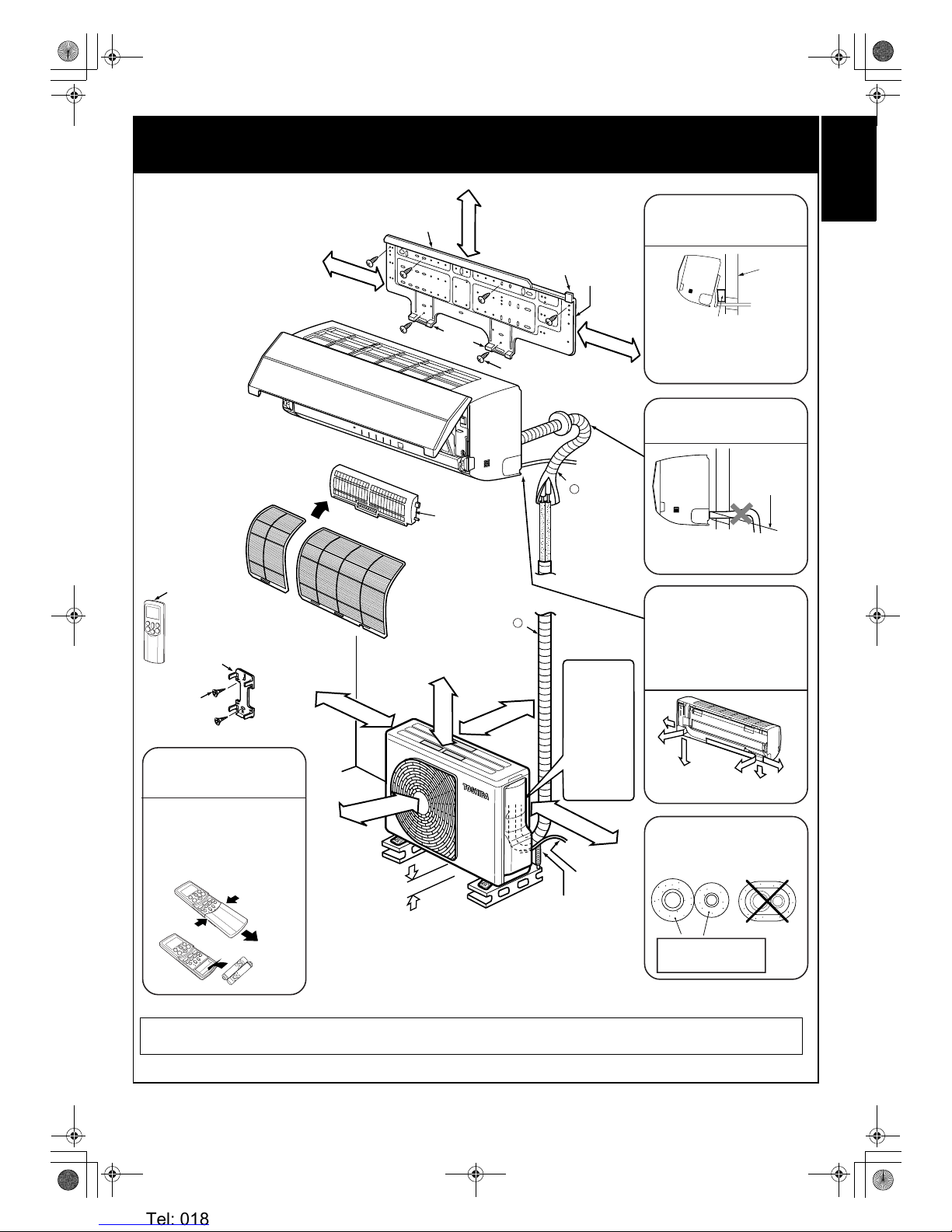
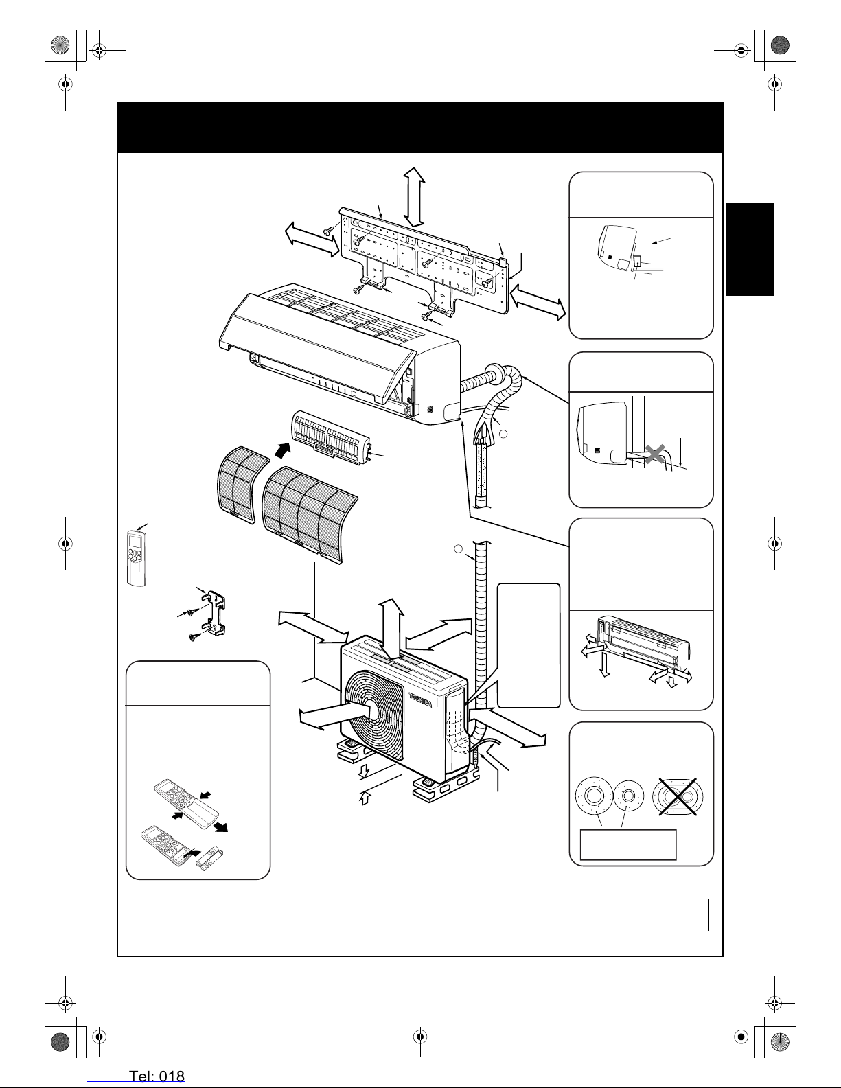
2 INSTALLATION DIAGRAM OF INDOOR AND OUTDOOR
UNITS
When using a multi-system outdoor unit, refer to the installation manual provided with the model
concerned.
Before installing the wireless
remote controller
100 mm or
more from
wall
Insert the cushion between
the indoor unit and wall, and
tilt the indoor unit for better
installation work.
Make sure the drain hose is
sloped downward.
The auxiliary piping can be
connected at the left, rear
left, rear right, right, bottom
right or bottom left as shown
below.
Extension drain hose
(Option: RB–821SW)
6 mm thick heat resisting
polyethylene foam
80 mm or more only
when unobstructed to
the front and both sides
d Remote controller holder
g Remote
controller holder
mounting screw
For the rear left and left
piping
Wall
Do not allow the drain hose
to become slack.
Cut the piping
hole slightly
sloped
Insulate the refrigerant pipes
separately, not together.
• With the remote controller
cover removed, correctly
load the supplied batteries
while observing their
polarity.
Cover
b Wireless remote controller
c Batteries
b Wireless remote controller
Hook
a Installation
plate
e Plasma pure filter
Shield pipe
(for extension
drain hose)
Z
Hook
Bottom right
Rear
right
Right
Left
Bottom left
Rear left
47 mm or more
74 mm or
more
140 mm or
more
250 mm or
more from wall
200 mm or
more
50 mm or more
from wall
f Mounting screw
Hook
Air filters
In principle,
leave open
As shown in the
figure, position
power cord and
connecting
cable
downward, and
lead out along
piping
connection port.
When installing the
outdoor unit, leave
open in at least two
of directions (A),
(B), (C) and (D)
shown in the right
figure.
Ensure sufficient
space to allow
drainage
(A)
(B)
(C)
(D)
power cord
Y
01_Installation_EN.fm Page 3 Tuesday, December 26, 2006 4:36 PM
Heronhill - for all your Toshiba requirements
Tel: 01823 665660
www.heronhill.co.uk
Fax: 01823 665807
4
EN
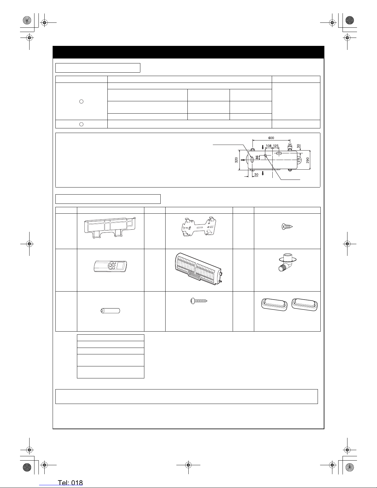
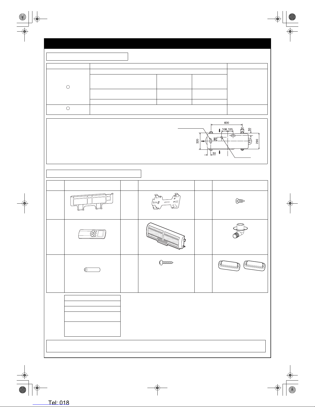
3 OPTIONAL PARTS, ACCESORIES AND TOOLS
Optional Installation Parts
Part Code Parts name Q’ty
Refrigerant piping
1 ea.
Indoor unit name
Liquid side
(Outer diameter)
Gas side
(Outer diameter)
RAS-B10SKVP-E, B13SKVP-E
RAS-M10SKCVP-E, M13SKCVP-E
6.35 mm 9.52 mm
RAS-B16SKVP-E, M16SKCVP-E 6.35 mm 12.7 mm
Shield pipe (for extension drain hose) (polyethylene foam, 6 mm thick) 1
Attachment bolt arrangement of outdoor unit
• Secure the outdoor unit with the attachment bolts and nuts if the unit is
likely to be exposed to a strong wind.
• Use φ8 mm or φ10 mm anchor bolts and nuts.
• If it is necessary to drain the defrost water, attach drain nipple to the
base plate of the outdoor unit before installing it.
Accessory and Installation Parts
Part No. Part name (Q’ty) Part No. Part name (Q’ty) Part No. Part name (Q’ty)
a
Installation plate x 1
d
Remote controller holder x 1
g
Remote controller holder
mounting screw
φ3.1 x 16L x 2
b
Wireless remote controller x 1
e
Plasma pure filter x 1
h
Drain nipple* x 1
(RAS-10SAVP-E, 13SAVP-E,
16SAVP-E)
c
Battery x 2
f
Mounting screw
φ4 x 25L x 6
i
Water-proof rubber cap* x 2
(RAS-10SAVP-E, 13SAVP-E,
16SAVP-E)
Others Name This model is not equipped with an
extension drain hose.
Option:
For the extension drain hose, use the
optionally available RB-821SW or a
commercially available one.
Parts marked with asterisk (*) are packaged with the
outdoor unit.
Owner’s manual
Installation manual
Important information
and warning*
B/W strips
(Energy efficiency labels)
When using a multi-system outdoor unit, refer to the installation manual provided with the model
concerned.
Y
Z
Suction side
Diffuser
Drain hole
(h)
Elongated drain
hole
(i)
01_Installation_EN.fm Page 4 Tuesday, December 26, 2006 4:36 PM
Heronhill - for all your Toshiba requirements
Tel: 01823 665660
www.heronhill.co.uk
Fax: 01823 665807
5 EN
ENGLISHFRANÇAISDEUTSCHITALIANOESPAÑOLΕΛΛΗΝΙΚΗPORTUGUÊS###SW######RU###
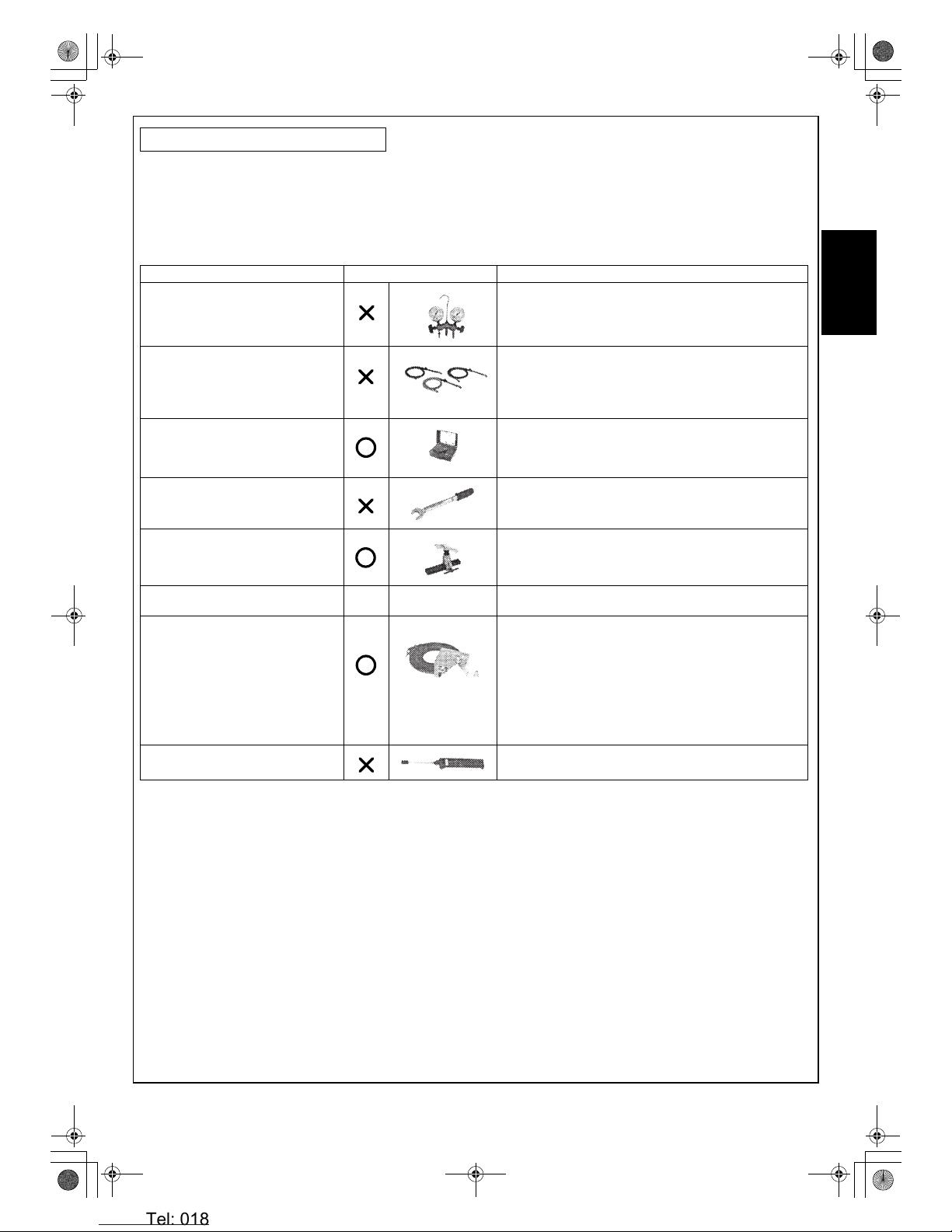
Changes in the product and components
On air conditioners using R410A, in order to prevent any other refrigerant from being accidentally charged, the service port diameter
size of the outdoor unit control valve (3 way valve) has been changed. (1/2 UNF 20 threads per inch)
• In order to increase the pressure resisting strength of the refrigerant piping, flare processing diameter and opposing flare nuts sizes
have been changed. (for copper pipes with nominal dimensions 1/2 and 5/8)
New tools for R410A
• Incidentally, the “refrigerant cylinder” comes with the refrigerant designation (R410A) and protector coating in the U.S’s ARI
specified rose color (ARI color code: PMS 507).
• Also, the “charge port and packing for refrigerant cylinder” requires 1/2 UNF 20 threads per inch corresponding to the charge hose’s
port size.
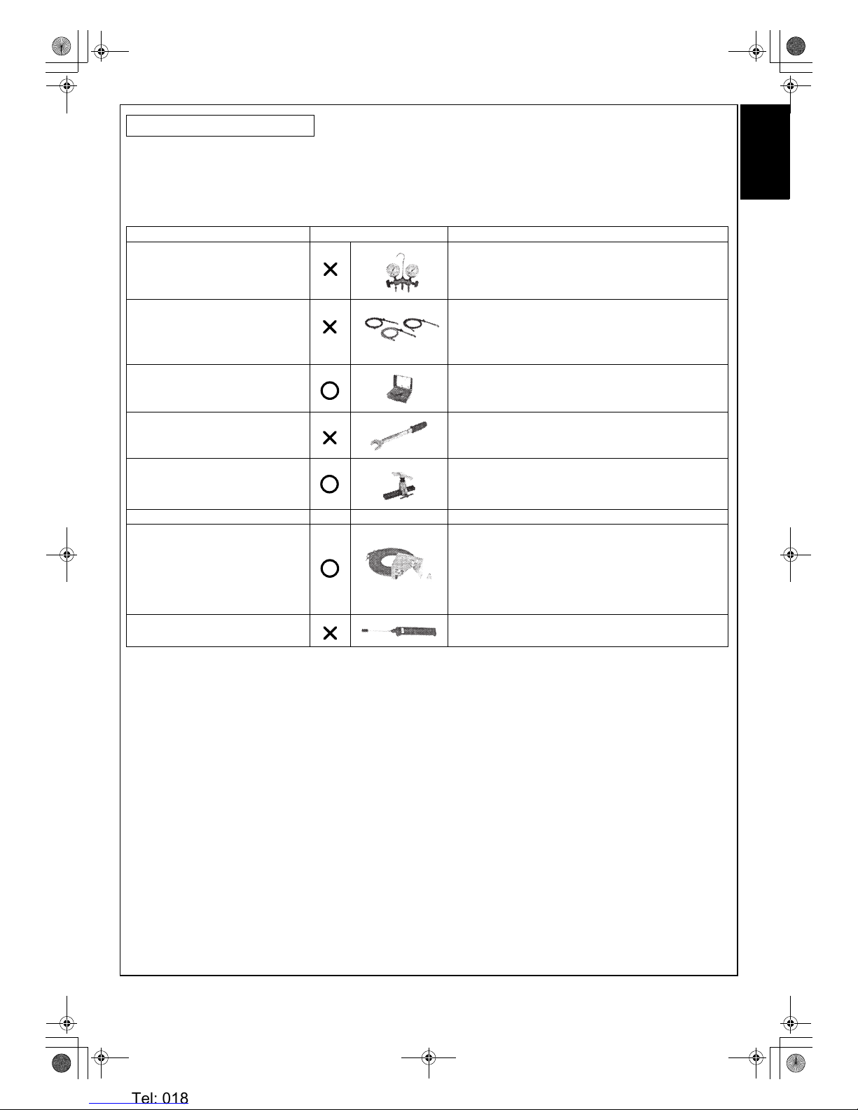
Installation/Service Tools
New tools for R410A Applicable to R22 model Changes
Gauge manifold As the working pressure is high, it is impossible to measure
the working pressure using conventional gauges. In order to
prevent any other refrigerant from being charged, the port
diameters have been changed.
Charge hose In order to increase pressure resisting strength, hose
materials and port sizes have been changed (to 1/2 UNF 20
threads per inch).
When purchasing a charge hose, be sure to confirm the
port size.
Electronic balance for refrigerant
charging
As working pressure is high and gasification speed is fast, it
is difficult to read the indicated value by means of charging
cylinder, as air bubbles occur.
Torque wrench
(nominal dia. 1/2, 5/8)
The size of opposing flare nuts have been increased.
Incidentally, a common wrench is used for nominal
diameters 1/4 and 3/8.
Flare tool (clutch type) By increasing the clamp bar’s receiving hole size, strength
of spring in the tool has been improved.
Gauge for projection adjustment — Used when flare is made by using conventional flare tool.
Vacuum pump adapter Connected to conventional vacuum pump. It is necessary to
use an adapter to prevent vacuum pump oil from flowing
back into the charge hose. The charge hose connecting
part has two ports — one is for conventional refrigerant (7/
16 UNF 20 threads per inch) and the other is for R410A. If
the vacuum pump oil (mineral) mixes with R410A, a sludge
may occur and damage the equipment.
Gas leakage detector Exclusive for HFC refrigerant.
01_Installation_EN.fm Page 5 Tuesday, December 26, 2006 4:36 PM
Heronhill - for all your Toshiba requirements
Tel: 01823 665660
www.heronhill.co.uk
Fax: 01823 665807
6
EN
• A place which provides enough space around the indoor unit as shown in the diagram. () see page 3.)
• A place where there are no obstacles near the air inlet and outlet.
• A place which allows easy installation of the piping to the outdoor unit.
• A place which allows the front panel to be opened.
• The indoor unit shall be installed so that the top of the indoor unit is positioned at least 2 m high.
Also, avoid putting anything on the top of the indoor unit.
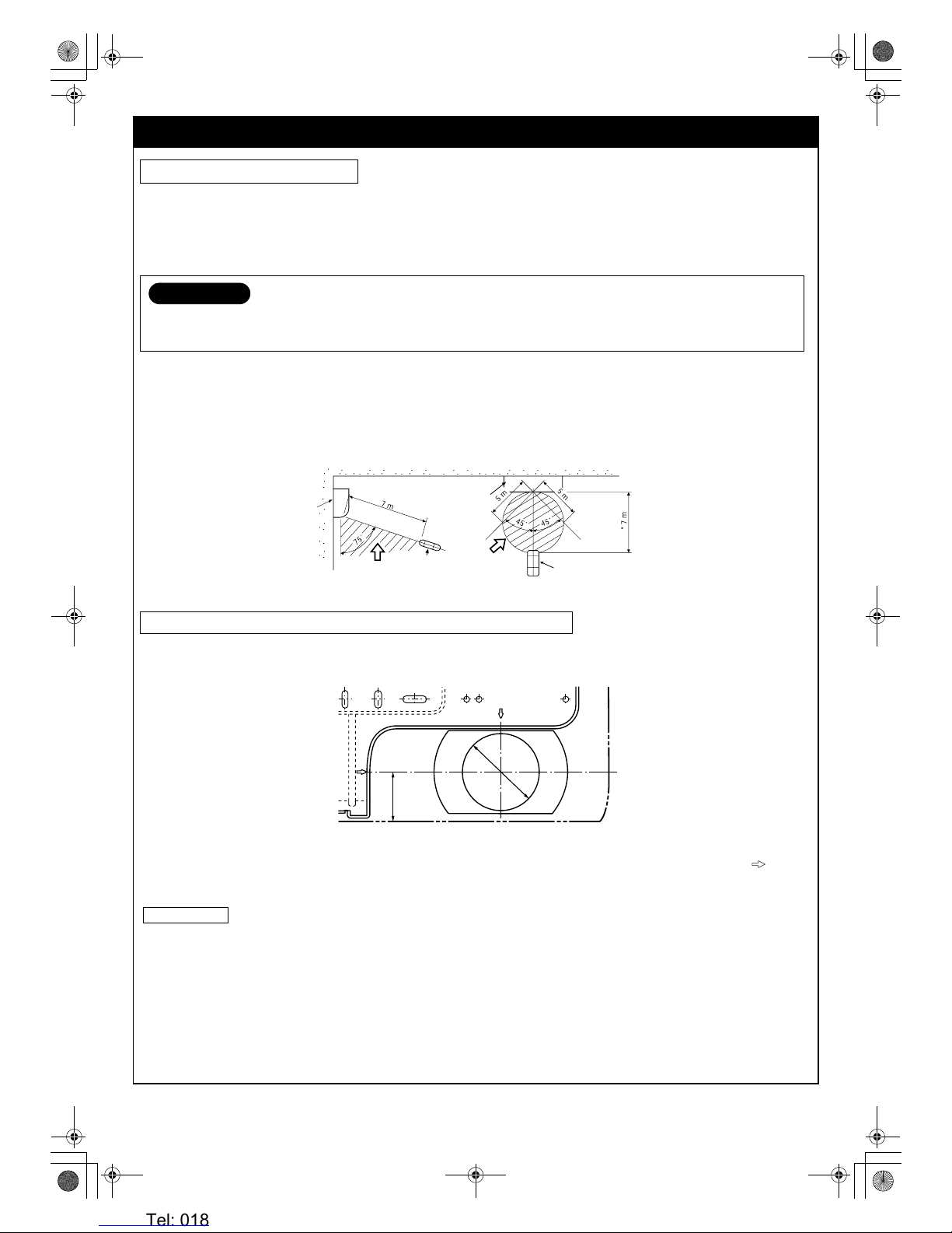
Remote controller
• Should be placed where there are no obstacles, such as curtains, that may block the signal.
• Do not install the remote controller in a place exposed to direct sunlight or close to a heating source, such as a stove.
• Keep the remote controller at least 1 m away from the nearest TV set or stereo equipment. (This is necessary to prevent image
disturbance or noise interference.)
• The location of the remote controller should be determined as shown below.
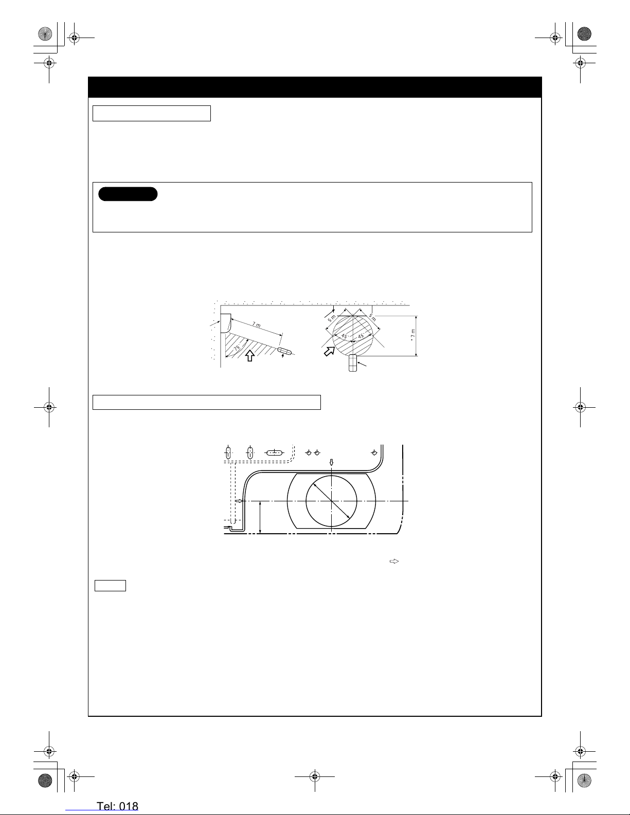
Drilling
When installing the refrigerant pipes from the rear.
1. Decide the installation plate mounting position on the wall.
2. Mark the corresponding pipe hole wall positions according to the positioning marks ( ) on the installation plate.
3. Drill the pipe holes (φ65 mm) slightly slanted downward to the outside.
NOTE
• When drilling into a wall that contains a metal lath, wire lath or metal plate, be sure to use a pipe hole brim ring sold separately.
4 INSTALLATION OF INDOOR UNIT
Installation Location
CAUTION
• Direct sunlight on the indoor unit wireless receiver should be avoided.
• The microprocessor in the indoor unit should not be too close to r-f sources.
(For details, see the owner’s manual.)
Drilling and Mounting Installation Plate
Indoor unit
(Top view)
(Side view)
Remote
controller
Reception
range
Remote controller
Indoor unit
*: Axial distance
Reception
range
42 mm
65 mm
The center of the
pipe hole
Pipe
hole
01_Installation_EN.fm Page 6 Tuesday, December 26, 2006 4:36 PM
Heronhill - for all your Toshiba requirements
Tel: 01823 665660
www.heronhill.co.uk
Fax: 01823 665807
7 EN
ENGLISHFRANÇAISDEUTSCHITALIANOESPAÑOLΕΛΛΗΝΙΚΗPORTUGUÊS###SW######RU###
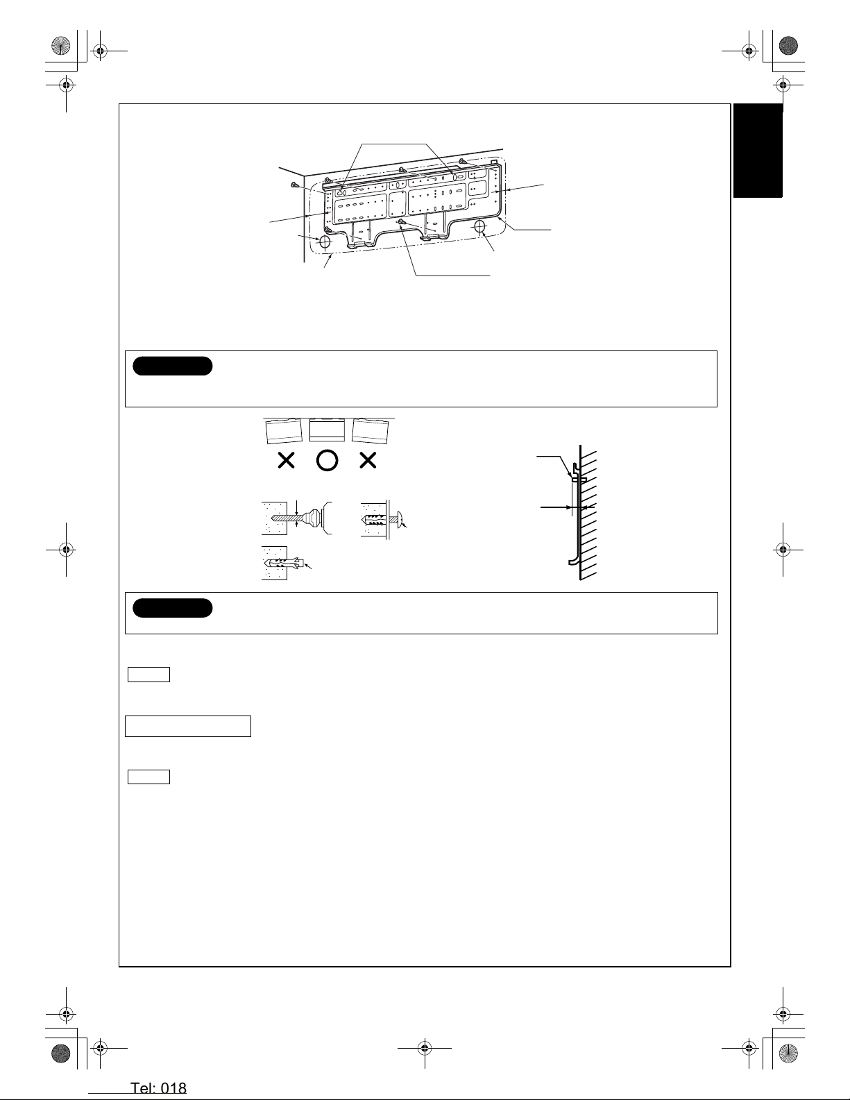
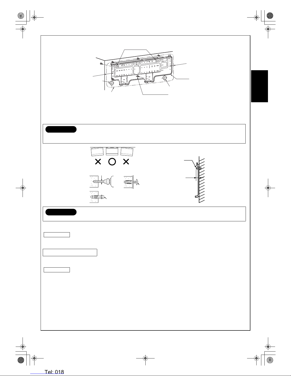
Mounting the installation plate
When the installation plate is directly mounted on the wall
1. Securely fit the installation plate onto the wall by screws with the upper and lower catches.
2. To mount the installation plate on a concrete wall use anchor bolts. Drill the anchor bolt holes as illustrated in the above figure.
3. Place the level at the top end of the installation plate, and check that the plate is horizontal.
• In case of block, brick, concrete or similar type walls, drill 5 mm dia. holes in the wall.
• Insert clip anchors for the
f mounting screws.
NOTE
• Install the installation plate using between 4 to 6 mounting screws, making sure all four corners are secure.
1. The supply voltage must be the same as the rated voltage of the air conditioner.
2. Prepare a power source for the exclusive use of the air conditioner.
NOTE
• Wire type: H07RN-F or 60245IEC66 (1.0 mm2)
CAUTION
When installing the installation plate with mounting screws, do not use anchor bolt holes. Otherwise the unit may fall down and
result in personal injury and property damage.
CAUTION
Failure to securely install the unit may result in personal injury and/or property damage if the unit falls.
Electrical Work
91 mm
25 mm
Anchor bolt holes
Indoor unit
Pipe hole
Pipe hole
f Mounting screw
a Installation plate
Clip anchor
(local parts)
f Mounting screw
φ4 x 25L
Anchor bolt
Projection 15 mm or less
5 mm dia. hole
01_Installation_EN.fm Page 7 Tuesday, December 26, 2006 4:36 PM
Heronhill - for all your Toshiba requirements
Tel: 01823 665660
www.heronhill.co.uk
Fax: 01823 665807
8
EN
NOTE
• Make sure the wire length is sufficient before performing wiring work.
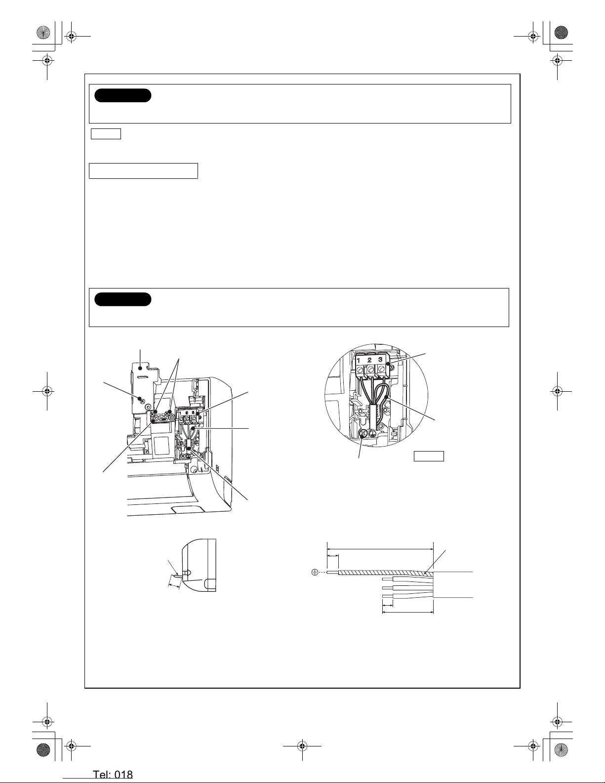
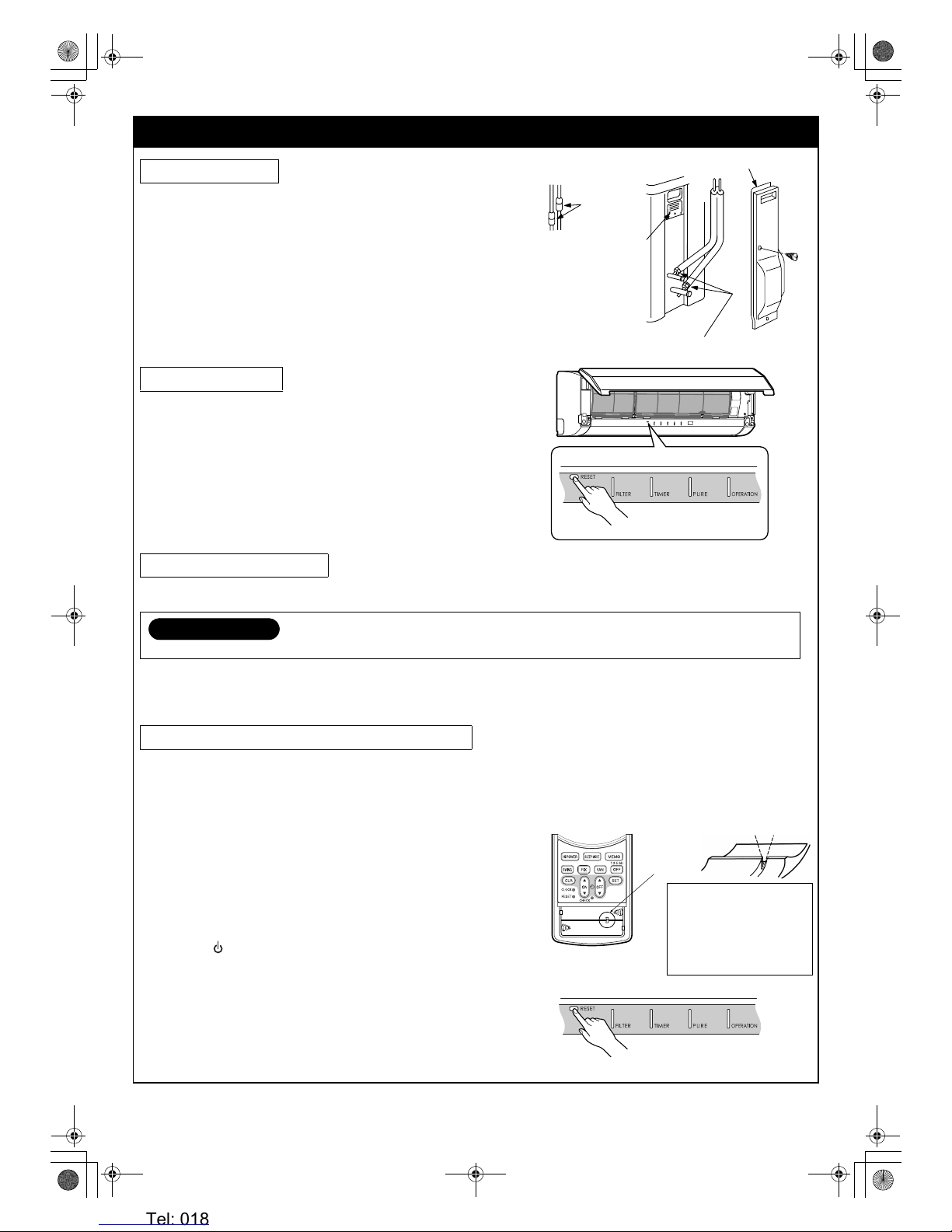
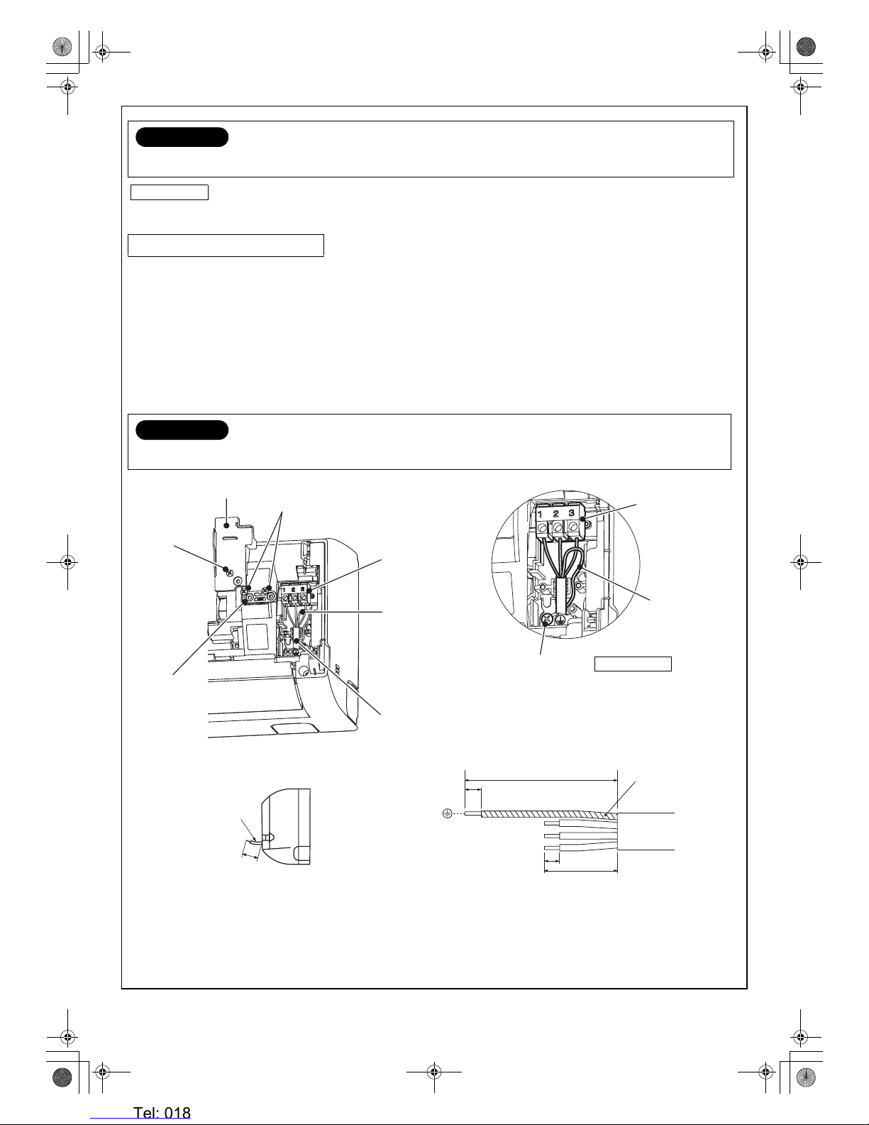
How to connect the connecting cable
Wiring the connecting cable can be carried out without removing the front panel.
1. Remove the air inlet grille. Open the air inlet grille upward and pull it toward you.
2. Remove the terminal cover and cord clamp.
3. Insert the connecting cable (or as according to local regulations/codes) into the pipe hole on the wall.
4. Pull the connecting cable through the cable slot on the rear panel so that it protrudes about 15 cm out of the front.
5. Insert the connecting cable fully into the terminal block and secure it tightly with screws.
Make a loop with the earth wire under the terminal block and secure it with the earth screw.
6. Tightening torque: 1.2 N·m (0.12 kgf·m)
7. Secure the connecting cable with the cord clamp.
8. Attach the terminal cover, rear plate bushing and air inlet grille on the indoor unit.
CAUTION
A switch or circuit breaker that can disconnect all poles must be included in the fixed wiring. Be sure to use an approved circuit
breaker or switch.
Wiring Connection
CAUTION
• Be sure to refer to the wiring system diagram labeled inside the front panel.
• Check local electrical regulations for any specific wiring instructions or limitations.
10 mm
110 mm
10 mm
50 mm
Screw
NOTE
• Connecting cable
(Indoor unit/outdoor unit)
• Wire type:
H07RN-F or 60245IEC66
(1.0 mm
2
)
Earth line
Connecting cable
Connecting cable
Cord clamp
Te r m i n a l c ov er
Te r mi na l b lo ck
Earth wire
about 15 cm
Screw
Terminal block
Earth wire
(loop)
Earth screw
01_Installation_EN.fm Page 8 Tuesday, December 26, 2006 4:36 PM
Heronhill - for all your Toshiba requirements
Tel: 01823 665660
www.heronhill.co.uk
Fax: 01823 665807
9 EN
ENGLISHFRANÇAISDEUTSCHITALIANOESPAÑOLΕΛΛΗΝΙΚΗPORTUGUÊS###SW######RU###
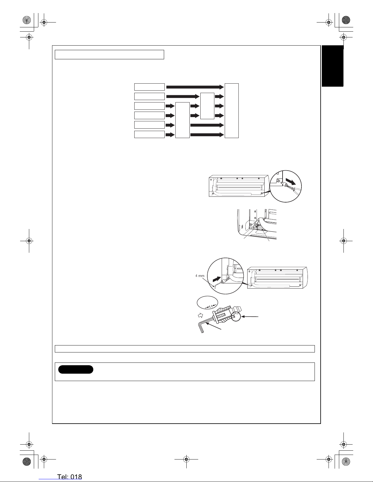
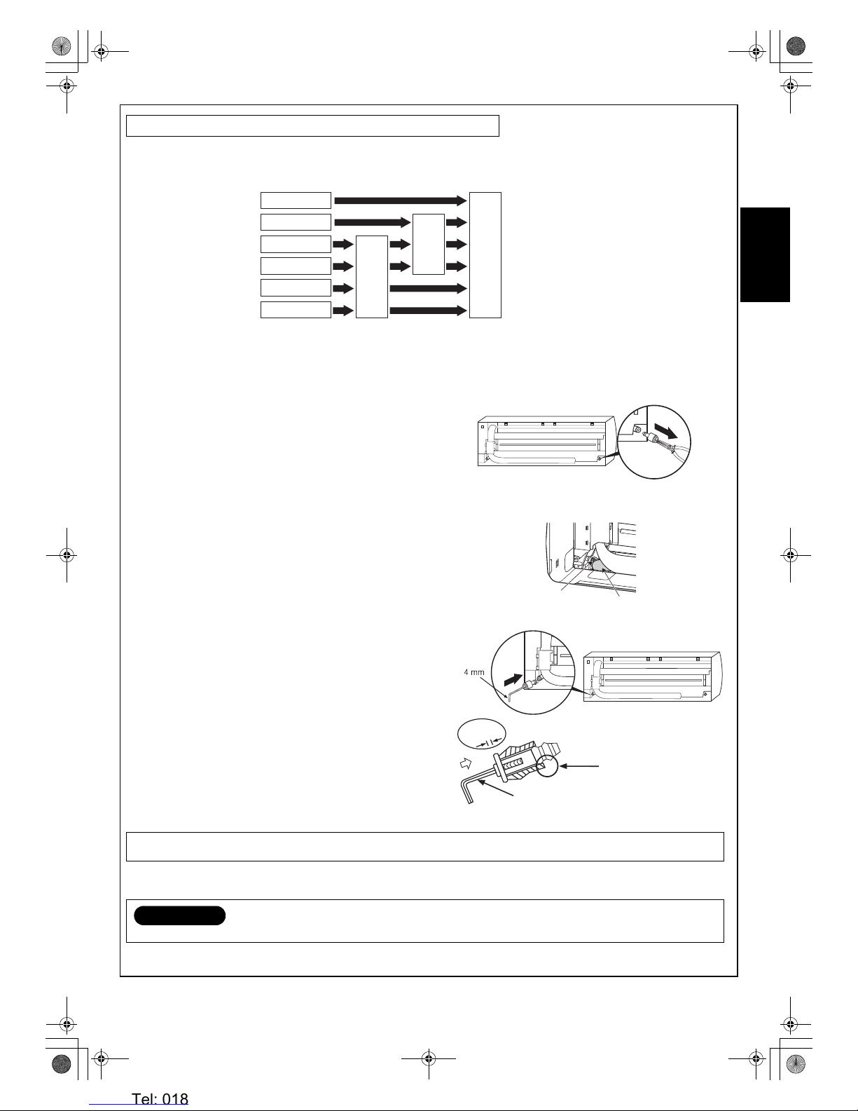
Piping and drain hose forming
• Since condensation results in machine trouble, make sure to insulate both the connecting pipes separately. (Use polyethylene foam
as insulating material.)
1. Die-cutting front panel slit
Cut out the slit on the left or right side of the front panel for the left or right connection and the slit on the bottom left or right side of the
front panel for the bottom left or right connection with a pair of nippers.
2. Changing drain hose
For left connection, left-bottom connection and rear-left connection’s piping, it is necessary to relocate the drain hose and drain cap.
• How to remove the drain cap
Clamp drain cap with needle-nose pliers, and pull out.
• How to remove the drain hose
The drain hose is secured in place by a screw.
Remove the screw securing the drain hose, then pull out the drain
hose.
• How to attach the drain cap
1. Insert hexagonal wrench (4 mm).
2. Firmly insert drain cap.
• How to attach the drain hose
Insert the drain hose firmly until the connector contacts the insulation, then secure it in place using the original screw.
Piping and Drain Hose Installation
Always use the original screw that secured the drain hose to the unit. Using a different screw may cause water to leak.
CAUTION
Securely insert the drain hose and drain cap; otherwise, water may leak.
Bottom right
Piping preparation
Changing
drain hose
Bottom left
Rear left
Rear right
Left
Right
Die-cutting front
panel slit
Screw
Drain hose
Do not apply lubricating oil
(refrigerant machine oil) when
inserting the drain ca p. If applied,
deterioration and leakage of the
drain plug may occur.
Insert a hexagon wrench
(4 mm)
No gap
01_Installation_EN.fm Page 9 Tuesday, December 26, 2006 4:36 PM
Heronhill - for all your Toshiba requirements
Tel: 01823 665660
www.heronhill.co.uk
Fax: 01823 665807
10
EN
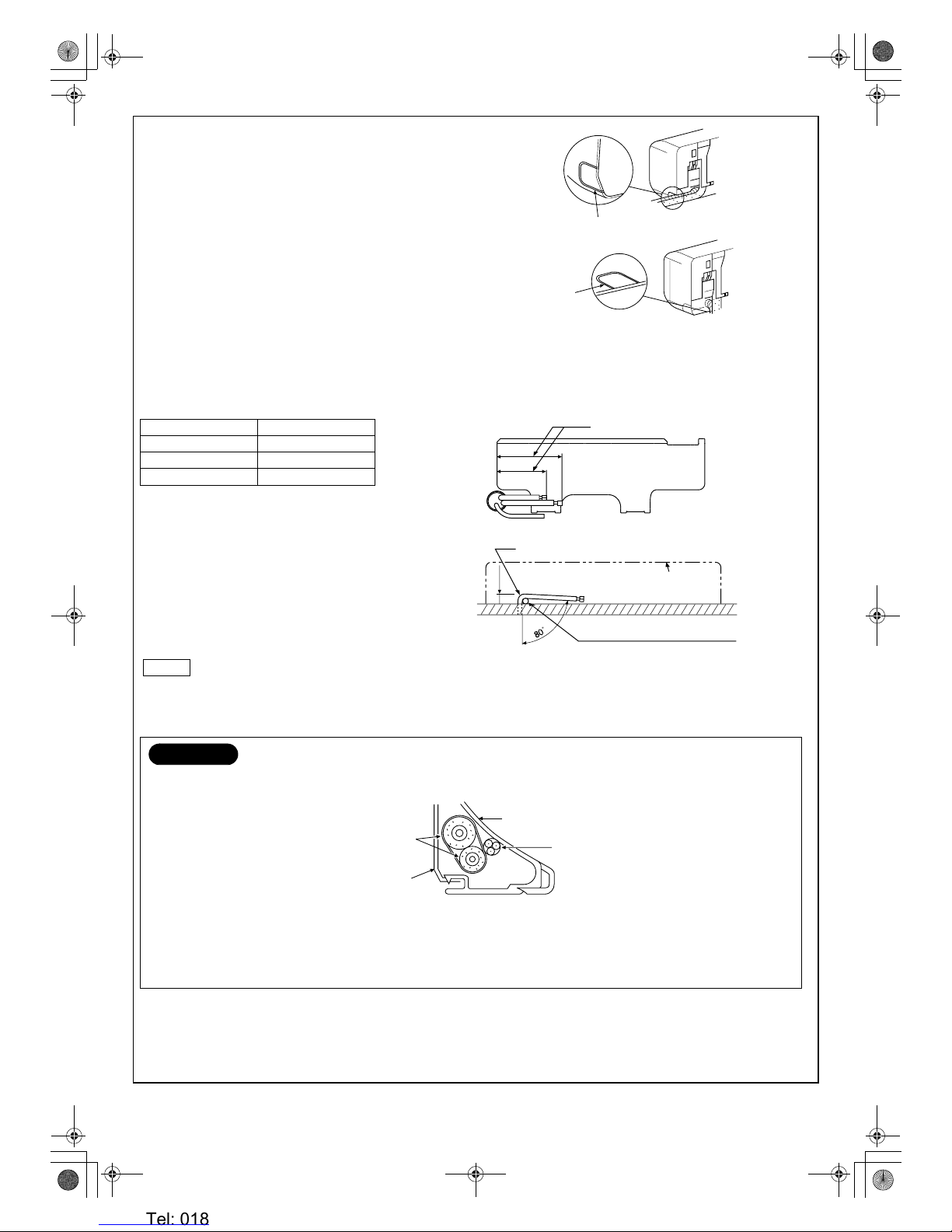
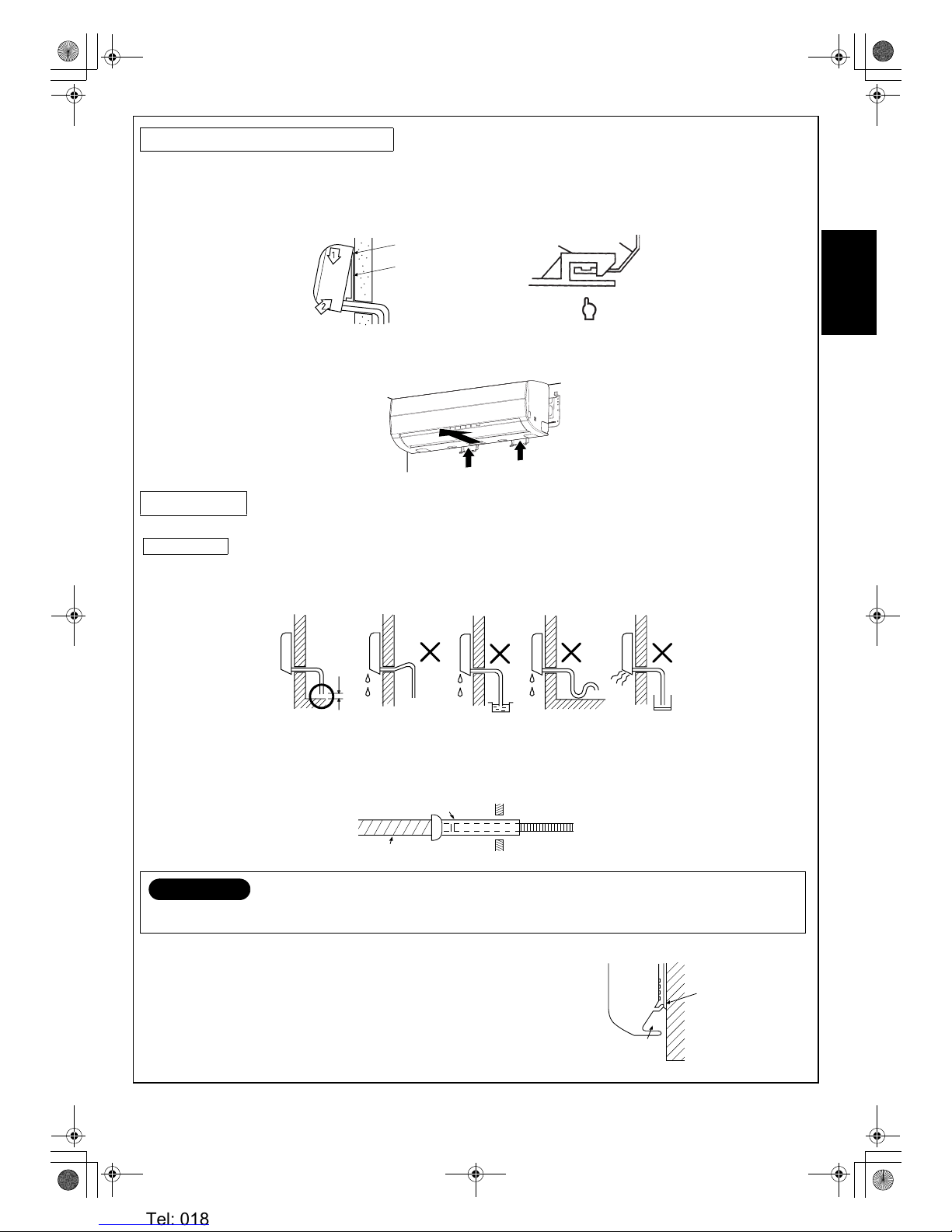
In case of right or left piping
• After making slits on the front panel with a knife or similar tool, cut
them out with a pair of nippers or an equivalent tool.
In case of bottom right or bottom left piping
• After making slits on the front panel with a knife or similar tool, cut
them out with a pair of nippers or an equivalent tool.
Left-hand connection with piping
Bend the connecting pipes so that they are positioned within 43 mm above the wall surface. If the connecting pipes are positioned
more than 43 mm above the wall surface, the indoor unit may be unstable. When bending the connecting pipe, make sure to use a
spring bender to avoid crushing the pipe.
Refer to the table below for the bending radius of each
connection pipe.
NOTE
If the pipe is incorrectly bent, the indoor unit may be unstable on the wall.
After passing the connecting pipe through the pipe hole, connect the connecting pipe to the auxiliary pipes and wrap the facing tape
around them.
Outer diameter Bending radius
6.35 mm 30 mm
9.52 mm 40 mm
12.7 mm 50 mm
CAUTION
• Bind the auxiliary pipes (two) and connecting cable with facing tape tightly. In case of leftward piping and rear-leftward piping,
bind the auxiliary pipes (two) only with facing tape.
• Carefully arrange the pipes so that none of the pipes stick out of the rear plate of the indoor unit.
• Carefully connect the auxiliary pipes and connecting pipes to each other and cut off the insulating tape wound on the
connecting pipe to avoid double-taping at the joint, moreover, seal the joint with the vinyl tape, etc.
• Since condensation can result in machine performance trouble, be sure to insulate both connecting pipes. (Use polyethylene
foam as insulating material.)
• When bending a pipe, be careful not to crush it.
Slit
Slit
43 mm
220 mm
170 mm
R30 or less (φ6.35), R40 or less (φ9.52), R50 or less (φ12.7)
Make sure to use a spring bender to avoid crushing the pipe.
(To the front of flare)
Liquid side
Gas side
Outward form of indoor unit
Use a screwdriver handle, etc.
To connect the pipe after installation of the unit (figure)
Installation plate
Indoor unit
Connecting cable
Auxiliary pipes
01_Installation_EN.fm Page 10 Tuesday, December 26, 2006 4:36 PM
Heronhill - for all your Toshiba requirements
Tel: 01823 665660
www.heronhill.co.uk
Fax: 01823 665807
11 EN
ENGLISHFRANÇAISDEUTSCHITALIANOESPAÑOLΕΛΛΗΝΙΚΗPORTUGUÊS###SW######RU###
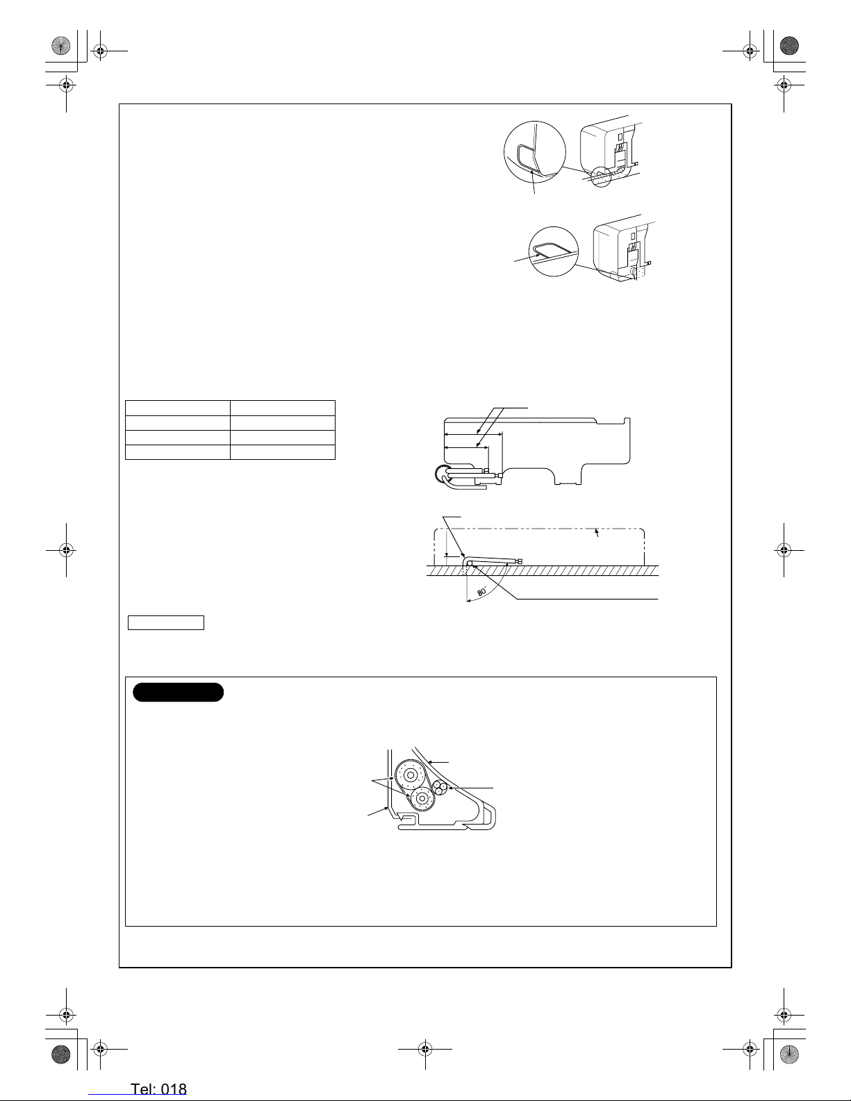
1. Pass the pipe through the hole in the wall, and hook the indoor unit on the installation plate at the upper hooks.
2. Swing the indoor unit to right and left to confirm that it is firmly hooked on the installation plate.
3. While pressing the indoor unit onto the wall, hook it at the lower part on the installation plate. Pull the indoor unit toward you to
confirm that it is firmly hooked on the installation plate.
• For detaching the indoor unit from the installation plate pull the indoor unit toward you while pushing the bottom up at the specified
places.
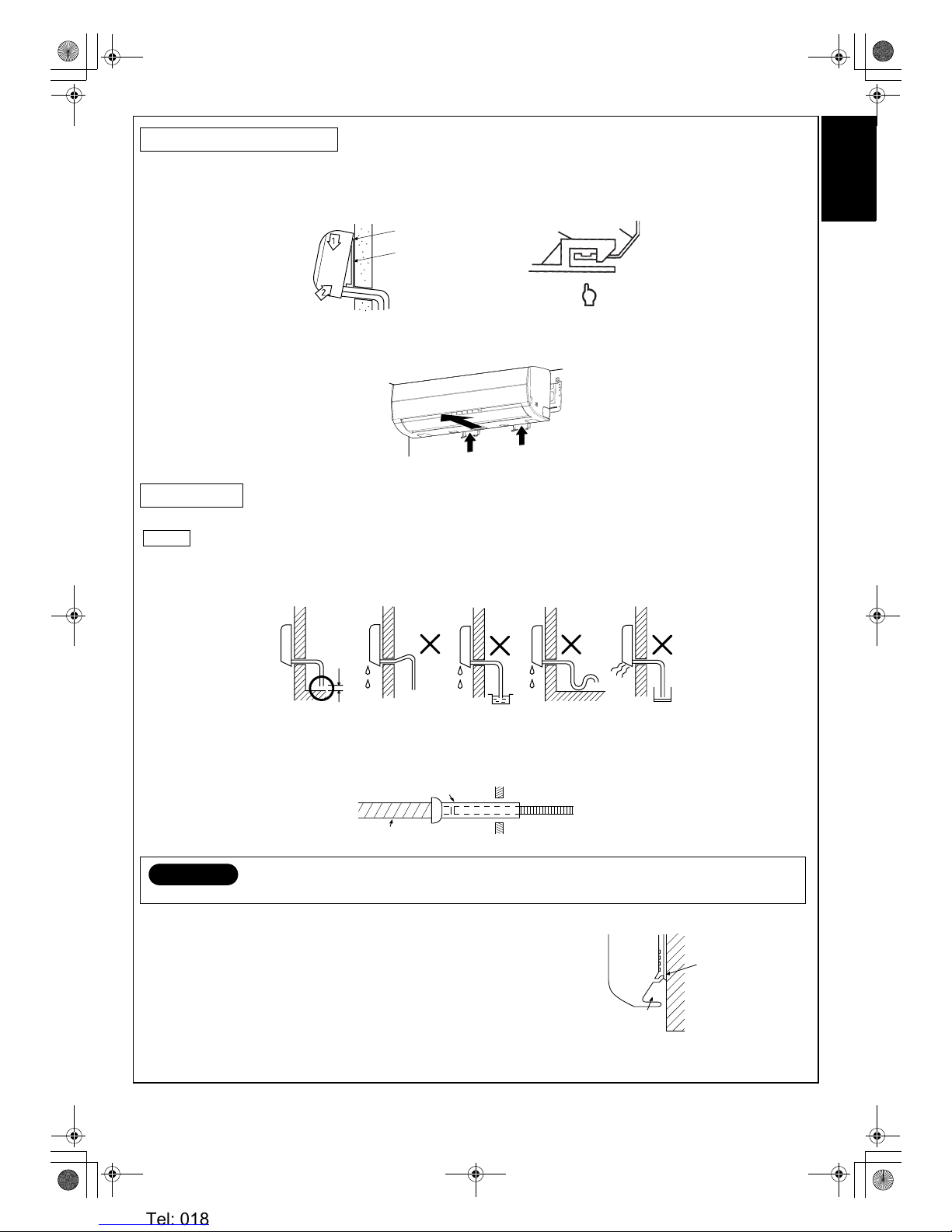
1. Run the drain hose at a downward sloped angle.
NOTE
• Hole should be made at a slight downward slant on the outdoor side.
2. Put water in the drain pan and make sure that the water is being drained outside.
3. When connecting extension drain hose, insulate the connection part of extension drain hose with shield pipe.
This air conditioner has been designed to drain water collected from
condensation which forms on the back of the indoor unit, to the drain pan.
Therefore, do not locate the power cord and other parts at a height above the
drain guide.
Indoor Unit Installation
Drainage
CAUTION
Install the drain pipe for proper drainage. Improper drainage can result in water dripping inside the room.
Hook here
Press (unhook)
a Installation plate
Hook
Push
Push
Do not put the drain hose
end into water.
Do not route the
drain hose upwards.
Do not form the drain
hose into a waved shape.
50 mm or
more
Do not put the drain hose
end in a drainage ditch.
Shield pipe
Drain hose
Inside the room
Extension drain hose
Space for pipes
Drain guide
Wall
01_Installation_EN.fm Page 11 Tuesday, December 26, 2006 4:36 PM
Heronhill - for all your Toshiba requirements
Tel: 01823 665660
www.heronhill.co.uk
Fax: 01823 665807

12
EN
• A place which provides enough space around the outdoor unit as shown in the diagram.
• A place which can bear the weight of the outdoor unit and does not allow an increase in noise level and vibration.
• A place where the operation noise and discharged air do not disturb neighbors.
• A place which is not exposed to a strong wind.
• A place free of combustible gases.
• A place which does not block a passageway.
• When the outdoor unit is to be installed in an elevated position, be sure to secure its feet.
• This air conditioner accepts a connection piping length from 2 m to 25 m.
• There is no need to add refrigerant as long as the length of the connection piping is 15 m or less.
• You will need to add 20 g of refrigerant per meter of added connection piping for installations requiring connection piping to be
between 16 m to 25 m.
• An allowable height level is up to 10 m.
• A place where the drain water does not cause any problems.
Precautions for Adding Refrigerant
• Use a scale having at least 10 g per index line presision when adding the refrigerant. Do not use a bathroom scale or similar
instrument.
• Use liquid refrigerant when refilling the refrigerant. Since the refrigerant is in liquid form, it can fill quickly. Therefore, perform the
filling operation carefully and insert the refrigerant gradually.
• Holes are provided on the base plate of the outdoor unit to ensure that the
defrost water produced during heating operations is drained off efficiently. If a
centralized drain is required when installing the unit on a balcony or wall, follow
the steps below to drain off the water.
1. Proceed with water-proofing by installing the water-proof rubber caps
i in the
2 elongated holes on the base plate of the outdoor unit.
[How to install the water-proof rubber caps]
1) Place four fingers into each cap, and insert the caps into the water drain
holes by pushing them into place from the underside of the base plate.
2) Press down on the outer circumferences of the caps to ensure that they
have been inserted tightly.
(Water leaks may result if the caps have not been inserted properly, if their
outer circumferences lift up or the caps catch on or wedge against
something.)
2. Install the drain nipple
h and a commercially available drain hose (with 16 mm
inside diameter), and drain off the water.
(For the position where the drain nipple
h is installed, refer to the installation
diagram of the indoor and outdoor units.)
• Check that the outdoor unit is horizontal, and route the drain hose at a
downward sloped angle with very little slack to the hose.
5 INSTALLATION OF OUTDOOR UNIT
Installation Location
CAUTION
1. Install the outdoor unit in a location where there are no obstructions near its air intake or air outlet.
2. When the outdoor unit is installed in a place that is always exposed to strong winds like on the coast or on a high story of a
building, secure the normal fan operation using a duct or a wind shield.
3. Especially in windy areas, install the unit to prevent the admission of wind.
4. Installation in the following places may result in trouble. Do not install the unit in such places.
• A place full of machine oil.
• A saline-place such as the coast.
• A place full of sulfide gas.
• A place where high-frequency waves are likely to be generated, such
as from audio equipment, welders, and medical equipment.
Draining the water
Strong
wind
i Water-proof rubber
caps (supplied with the
outdoor unit)
h Drain nipple
Base plate
Commercially available
drain hose
Do not use ordinary gard en hose, which can flatten and
prevent drainage.
Base plate
h Drain nipple
01_Installation_EN.fm Page 12 Tuesday, December 26, 2006 4:36 PM
Heronhill - for all your Toshiba requirements
Tel: 01823 665660
www.heronhill.co.uk
Fax: 01823 665807
13 EN
ENGLISHFRANÇAISDEUTSCHITALIANOESPAÑOLΕΛΛΗΝΙΚΗPORTUGUÊS###SW######RU###
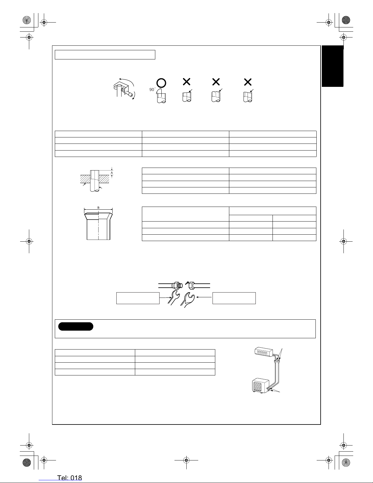
Flaring
1. Cut the pipe with a pipe cutter.
2. Insert a flare nut into the pipe, and flare the pipe.
• Projection margin in flaring: A (Unit: mm)
Rigid (Clutch type)
Imperial (Wing nut type)
3. Flaring size : B (Unit : mm)
• In case of flaring for R410A with the conventional flare tool, pull it out approx. 0.5 mm more than that of R22 to adjust the
specified flare size. The copper pipe gauge is useful for adjusting projection margin size.
Tighten the connection
Align the centers of the connecting pipes and tighten the flare nut as much as possible with your fingers. Then tighten the nut with a
wrench and torque wrench as shown in the figure.
(Unit: N·m)
• Tightening torque for connection of flare pipe
The pressure of R410A is higher than R22. (Approx. 1.6 times.) Therefore securely
tighten the flare pipes which connect the outdoor unit and the indoor unit with the
specified tightening torque using a torque wrench.
If any flare pipe is incorrectly connected, it may cause not only a gas leakage but also trouble in the refrigeration cycle.
Refrigerant Piping Connection
Outer diameter of copper pipe R410A tool used Conventional tool used
6.35 0 to 0.5 1.0 to 1.5
9.52 0 to 0.5 1.0 to 1.5
12.7 0 to 0.5 1.0 to 1.5
Outer diameter of copper pipe R410A
6.35 1.5 to 2.0
9.52 1.5 to 2.0
12.7 2.0 to 2.5
Outer diameter of copper pipe
B
R410A R22
6.35 9.1 9.0
9.52 13.2 13.0
12.7 16.6 16.2
CAUTION
• Do not apply excessive force. Otherwise, the nut may break.
Outer diameter of copper pipe Tightening torque
φ6.35 mm 14 to 18 (1.4 to 1.8 kgf·m)
φ9.52 mm 33 to 42 (3.3 to 4.2 kgf·m)
φ12.7 mm 50 to 62 (5.0 to 6.2 kgf·m)
Obliquity
Roughness
Warp
Die
Pipe
+0
–0.4
Half union
Flare nut
Externally threaded side
Use a wrench to secure.
Internally threaded side
Use a torque wrench to tighten.
Flare at indoor
unit side
Flare at outdoor unit
side
01_Installation_EN.fm Page 13 Tuesday, December 26, 2006 4:36 PM
Heronhill - for all your Toshiba requirements
Tel: 01823 665660
www.heronhill.co.uk
Fax: 01823 665807
14
EN
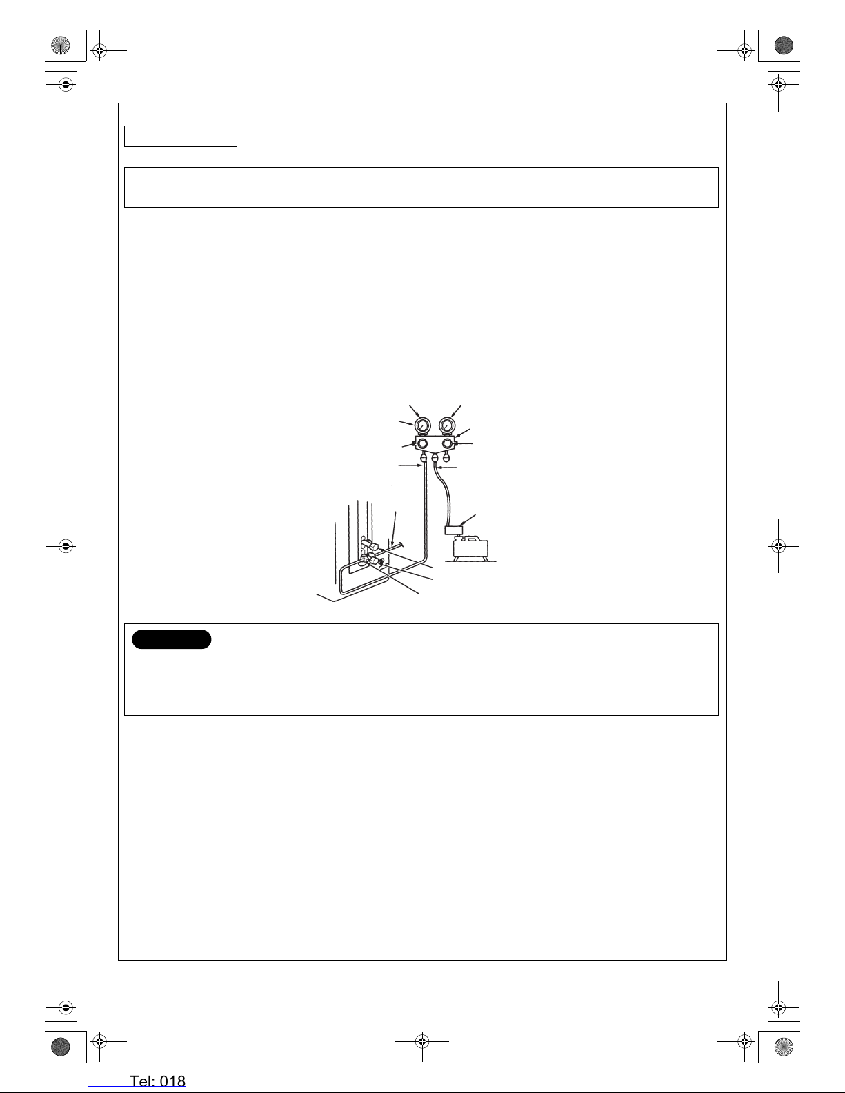
After the piping has been connected to the indoor unit, perform the air purge.
Use a vacuum pump
Be sure to use a vacuum pump with counter-flow prevention function so that oil inside the pump does not flow back into the air
conditioner pipes when the pump stops. (If oil inside the vacuum pump enters the air conditioner circuit which uses R410A, trouble
with the refrigeration system may develop.)
1. Connect the charge hose from the manifold valve to the service port of the gas side packed valve.
2. Connect the charge hose to the port of the vacuum pump.
3. Open fully the low pressure side handle of the gauge manifold valve.
4. Operate the vacuum pump to begin evacuating. Perform evacuating for about 15 minutes if the piping length is 20 meters (15
minutes for 20 meters) (assuming a pump capacity of 27 liters per minute). Confirm that the compound pressure gauge reading is
–101 kPa (–76 cmHg).
5. Close the low pressure valve handle of gauge manifold.
6. Open fully the valve stem of the packed valves (both sides of Gas and Liquid).
7. Remove the charging hose from the service port.
8. Securely tighten the caps on the packed valves.
Evacuating
AIR PURGE
Evacuate the air in the connecting pipes and in the indoor unit using a vacuum pump. Do not use the refrigerant in the outdoor unit.
For details, see the vacuum pump manual.
CAUTION
• IMPORTANT POINTS FOR PIPING WORK
(1) Prevent dust and moisture from entering the pipes.
(2) Tighten connections carefully (between pipes and unit).
(3) Evacuate the air in the connecting pipes using a VACUUM PUMP.
(4) Check for gas leaks at all connections.
Compound pressure gauge
–101 kPa
(–76 cmHg)
Handle Lo
Charge hose
(For R410A only)
Pressure gauge
Manifold valve
Handle Hi
(Keep full closed)
Charge hose
(For R410A only)
Connecting
pipe
Vacuum pump adapter for counterflow prevention (For R410A only)
Vac uum
pump
Packed valve at liquid side
Packed valve at gas side
Service port
(Valve core (Setting pin))
01_Installation_EN.fm Page 14 Tuesday, December 26, 2006 4:36 PM
Heronhill - for all your Toshiba requirements
Tel: 01823 665660
www.heronhill.co.uk
Fax: 01823 665807
15 EN
ENGLISHFRANÇAISDEUTSCHITALIANOESPAÑOLΕΛΛΗΝΙΚΗPORTUGUÊS###SW######RU###
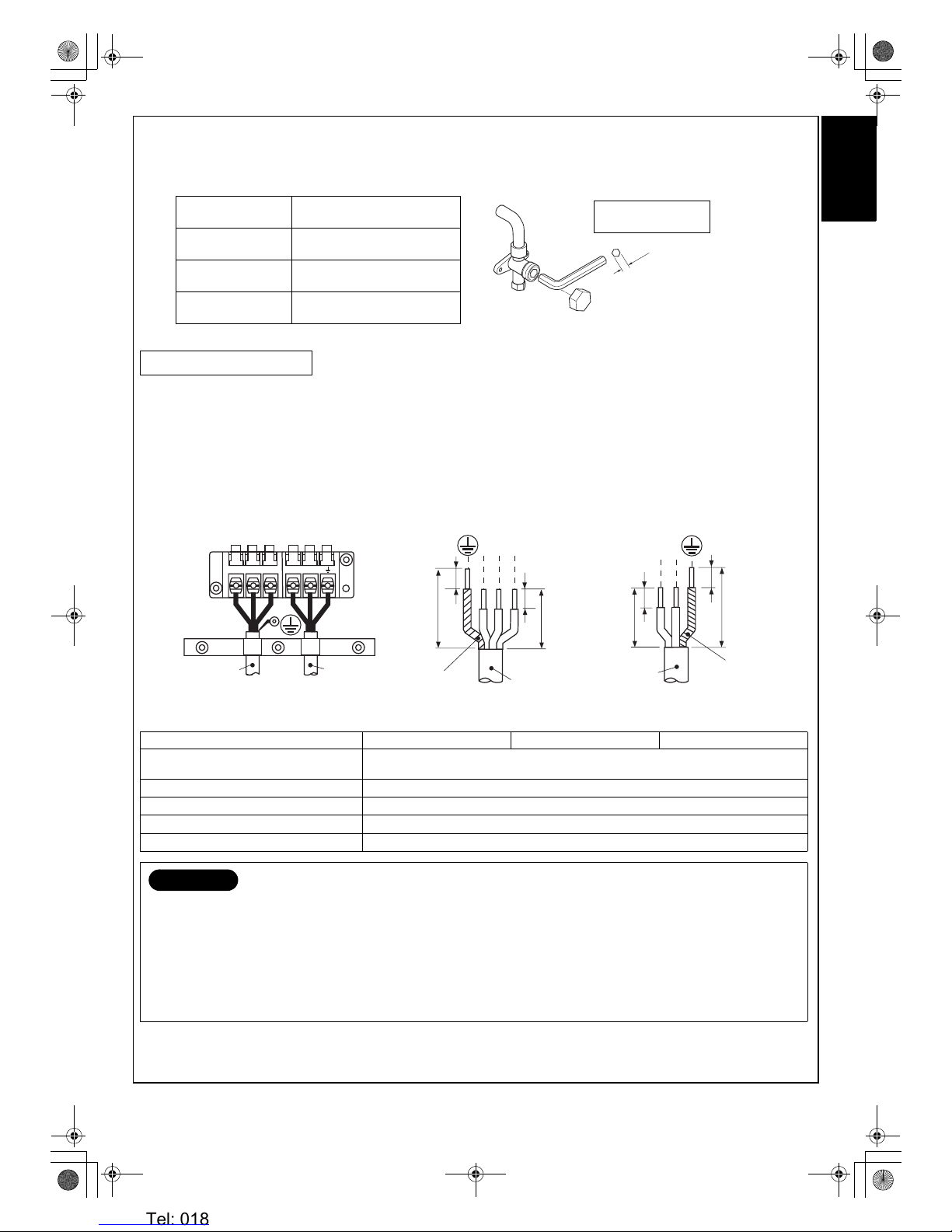
Packed valve handling precautions
• Open the valve stem until it touches the stopper. Once it is in contact with the stopper, refrain from applying any more force than is
necessary.
• Securely tighten the valve stem cap with torque in the following table:
1. Remove the valve cover, the electric parts cover and the cord clamp from the outdoor unit.
2. Connect the connecting cable to the terminal as identified by the matching numbers on the terminal block of indoor and outdoor
unit.
3. Insert the power cord and the connecting cable fully into the terminal block and secure it tightly with screws.
4. Use vinyl tape, etc. to insulate the cords which are not going to be used. Locate them so that they do not touch any electrical or
metal parts.
5. Secure the power cord and the connecting cable with the cord clamp.
6. Attach the electric parts cover and the valve cover on the outdoor unit.
Stripping length of connecting cable
Wiring Connection
Model RAS-10SAVP-E RAS-13SAVP-E RAS-16SAVP-E
Power source
220–240 V ~50 Hz
220 V ~60 Hz
Maximum running current 12.5 A
Installation fuse rating 16 A breaker or fuse (all types can be used)
Power cord H07RN-F or 60245IEC66 (1.5 mm
2
)
Connecting cable
Wire type: H07RN-F or 60245IEC66 (1.0 mm
2
)
CAUTION
• Incorrect wiring connection may cause electrical parts to burn out.
• Be sure to comply with local regulations/codes when running the wire from outdoor unit to indoor unit. (Size of wire and wiring
method etc.)
• Every wire must be securely connected.
• If incorrect or incomplete wiring is carried out, fire or smoke may result.
• Prepare the power supply for the exclusive use of the air conditioner.
• This product can be connected to the main breaker.
Connection to fixed wiring: A switch or circuit breaker that can disconnect all poles must be included in the fixed wiring. Be sure
to use an approved circuit breaker or switch.
4 mm
Hexagon wrench
is required.
Gas side
(φ12.7 mm)
50 to 62 N·m
(5.0 to 6.2 kgf·m)
Gas side
(φ9.52 mm)
33 to 42 N·m
(3.3 to 4.2 kgf·m)
Liquid side
(φ6.35 mm)
14 to 18 N·m
(1.4 to 1.8 kgf·m)
Service port 14 to 18 N·m
(1.4 to 1.8 kgf·m)
30
30
10
L
N
1012
3
123 LN
10
10
40
40
Connecting
cable
Ter mi na l bl oc k
Earth line
Connecting
cable
Power cord
Power cord
Earth line
01_Installation_EN.fm Page 15 Tuesday, January 9, 2007 10:36 AM
Heronhill - for all your Toshiba requirements
Tel: 01823 665660
www.heronhill.co.uk
Fax: 01823 665807
16
EN
• Check the flare nut connections for gas leaks with a
gas leak detector and/or soapy water.
To test the system, press and hold RESET button for 10 sec.
(There will be one short beep.)
This product is designed so that, after a power failure, it can restart automatically in the same operating mode as before the power
failure.
How to set the Auto Restart
• Press and hold the RESET button for about 3 seconds. After 3 seconds, three short electric beeps will be heard to inform you that
the Auto Restart has been selected.
• To cancel the Auto Restart, follow the steps described in the section Auto Restart Function of the Owner’s Manual.
• If two indoor units are installed in the same room or adjoining rooms, when the user tries to operate only one unit, both units may
receive the same remote controller signal and operate. This can be prevented by changing one of the indoor units and remote
controllers to setting “B” (the default setting for both units is “A”).
• If the indoor unit and remote controller settings are different, the remote controller signal is not accepted.
1. Setting the remote controller
a Slide open the remote controller cover and remove the batteries.
b Cut the jumper wire inside the battery compartment using nippers.
• The jumper wire should not remain in contact after being cut. Also,
be careful not to let plastic scraps, jumper wire cuttings or other
debris enter the inside of the remote controller.
c Insert the batteries. “B” appears in the remote controller display.
2. Setting the unit
Press the RESET button to start automatic operation.
3. Press the button of the remote controller that was set in step 1 to
stop the air conditioner. (This operation will change the setting to “B”.)
4. Check that the remote controller operates the indoor unit.
6 TEST OPERATION
Gas Leak Test
Test Operation
Auto Restart Setting
INFORMATIONINFORMATION
The product was shipped with Auto Restart function in the OFF position. Turn it ON as required.
If the air conditioner operates incorrectly
Val ve c over
Check
places for
indoor unit
Electric parts cover
Check places for outdoor unit
RESET button
Jumper wir e
Cutting direction
When switching between
settings “A” and “B”, always
switch the indoor unit board
and the remote controller as a
pair. (Otherwise, the indoor
unit will not accept the remote
controller’s signals.)
RESET button
01_Installation_EN.fm Page 16 Tuesday, December 26, 2006 4:36 PM
Heronhill - for all your Toshiba requirements
Tel: 01823 665660
www.heronhill.co.uk
Fax: 01823 665807
1 FR
FRANÇAIS
1 MESURES DE SECURITE
Pour utilization grand public
Le cordon d’alimentation de l’unité extérieure doit être un cordon flexible à gaine en polychloroprène de 1,5 mm2 (H07RN-F ou
60245IEC66).
ATTENTION
Installation du climatiseur à nouveau fluide frigorigène
• CE CLIMATISEUR ADOPTE LE NOUVEAU FLUIDE FRIGORIGENE HFC (R410A) QUI NE DETRUIT PAS LA COUCHE
D’OZONE.
Le fluide frigorigène R410A est susceptible d’être affecté par des impuretés comme de l’eau, une membrane s’oxydant et des
huiles car sa pression de fonctionnement est environ 1,6 fois celle du fluide frigorigène R22. Conjointement à l’adoption du
nouveau fluide frigorigène, l’huile de la machine frigorifique a également été changée. Par conséquent, pendant les travaux
d’installation, veillez à ce que de l’eau, de la poussière, de l’ancien fluide frigorigène ou de l’huile pour machine frigorifique ne
pénètre pas dans le circuit du climatiseur R410A à nouveau type de fluide frigorigène.
Afin d’éviter le mélange de fluide frigorigène ou d’huile pour machine frigorifique, les dimensions des sections de raccordement
du port de chargement de l’appareil principal et les outils d’installation sont différents de ceux utilisés pour les climatiseurs à
fluide frigorigène conventionnels. Par conséquent, des outils spéciaux, comme indiqué à la page 5, sont nécessaires pour les
appareils à nouveau fluide frigorigène (R410A). Pour raccorder les tuyaux, utilisez de nouveaux matériaux de tuyauterie propres
ayant une résistance élevée à la pression conçus uniquement pour le fluide R410A, afin que de l’eau et/ou de la poussière ne
pénètre. En outre, n’utilisez pas la tuyauterie existante car elle pose quelques problèmes de résistance à la pression et qu’elle
peut contenir des impuretés.
ATTENTION
POUR DEBRANCHER L’APPAREIL DE L’ALIMENTATION PRINCIPALE
Un commutateur ou disjoncteur qui peut déconnecter tous les pôles doit être incorporé au câblage fixe. Veillez à utiliser un
disjoncteur ou commutateur agréé.
02_Installation_FR.fm Page 1 Tuesday, January 9, 2007 12:33 PM
Heronhill - for all your Toshiba requirements
Tel: 01823 665660
www.heronhill.co.uk
Fax: 01823 665807
2
FR
DANGER
• UTILISATION PAR DES PERSONNES QUALIFIEES SEULEMENT.
• COUPEZ L’ALIMENTATION PRINCIPALE AVANT D’EFFECTUER DES TRAVAUX D’ELECTRICITE. VERIFIEZ QUE TOUS
LES INTERRUPTEURS D’ALIMENTATION SONT REGLES SUR ARRET. SINON IL Y A UN RISQUE DE DECHARGE
ELECTRIQUE.
• RACCORDEZ CORRECTEMENT LE CABLE DE CONNEXION. SI LE CABLE DE CONNEXION EST MAL RACCORDE,
DES PIECES ELECTRIQUES PEUVENT ETRE ENDOMMAGEES.
• AVANT L’INSTALLATION, VERIFIEZ QUE LE FIL DE TERRE N’EST PAS CASSE OU DEBRANCHE. SINON IL Y A UN
RISQUE DE DECHARGE ELECTRIQUE.
• N’INSTALLEZ PAS L’APPAREIL DANS UN ENDROIT OU IL PEUT Y AVOIR UNE FUITE DE GAZ INFLAMMABLE. UN
INCENDIE POURRAIT SE PRODUIRE SI DU GAZ INFLAMMABLE S’ACCUMULE AUTOUR DE L’APPAREIL.
• AFIN D’EVITER QUE L’UNITE INTERIEURE SURCHAUFFE ET POSE UN RISQUE D’INCENDIE, PLACEZ L’UNITE LOIN
(A PLUS DE 2 M.) DE SOURCES DE CHALEUR COMME DES RADIATEURS, APPAREILS DE CHAUFFAGE,
CALORIFERES, POELES, ETC.
• LORS DU DEPLACEMENT DU CLIMATISEUR POUR L’INSTALLER DANS UN AUTRE ENDROIT, FAITES TRES
ATTENTION QUE LE FLUIDE FRIGORIGENE SPECIFIE (R410A) NE SE MELANGE PAS AVEC UN AUTRE CORPS
GAZEUX DANS LE CIRCUIT DE REFRIGERATION. SI DE L’AIR OU UN AUTRE GAZ SE MELANGE AU FLUIDE
FRIGORIGENE, LA PRESSION DE GAZ DANS LE CIRCUIT DE REFRIGERATION DEVIENDRA ANORMALEMENT
ELEVEE, CE QUI POURRAIT PROVOQUER UN ECLATEMENT DU TUYAU OU DES BLESSURES CORPORELLES.
• AU CAS OU DU GAZ REFRIGERANT FUIT DU TUYAU PENDANT L’INSTALLATION, FAITES IMMEDIATEMENT ENTRER
DE L’AIR FRAIS DANS LA PIECE. SI LE GAZ REFRIGERANT EST CHAUFFE, DU GAZ TOXIQUE PEUT SE FORMER.
• LORS DE L’INSTALLATION DU CLIMATISEUR, ASSUREZ-VOUS QUE LE TUYAU DE FLUIDE FRIGORIGENE EST
SOLIDEMENT RACCORDE AVANT DE FAIRE FONCTIONNER LE COMPRESSEUR. SI LE COMPRESSEUR EST
UTILISE SANS QUE LE TUYAU DE FLUIDE FRIGORIGENE SOIT RACCORDE, CE QUI SIGNIFIE QUE LE ROBINET DE
SERVICE RESTERA OUVERT, DE L’AIR, ETC. SERA ASPIRE A L’INTERIEUR, PROVOQUANT UNE AUGMENTATION A
UN NIVEAU ANORMALEMENT ELEVE DE LA PRESSION DANS LE CYCLE DE REFRIGERATION, CE QUI PEUT
PROVOQUER UNE RUPTURE, DES BLESSURES, ETC.
• LORS DES OPERATIONS D’EVACUATION, ARRETEZ LE COMPRESSEUR AVANT DE DEBRANCHER LE TUYAU DE
FLUIDE FRIGORIGENE. SI LE TUYAU DE FLUIDE FRIGORIGENE EST DEBRANCHE ALORS QUE LE ROBINET DE
SERVICE EST ENCORE OUVERT ET QUE LE COMPRESSEUR EST ENCORE EN MARCHE, DE L’AIR, ETC., SERA
ASPIRE A L’INTERIEUR AVEC POUR CONSEQUENCE UNE ELEVATION ANORMALE DE PRESSION DANS LE CYCLE
DE REFRIGERATION RISQUANT DE PROVOQUER UNE RUPTURE, D’OCCASIONNER DES BLESSURES, ETC.
AVERTISSEMENT
• Ne modifiez jamais cet appareil en retirant l’une des protections de sécurité.
• L’installation du climatiseur doit être effectuée dans un endroit qui peut supporter suffisamment son poids. Sinon, il y a un
risque de dégâts matériels et des blessures corporelles.
• L’appareil doit être installé conformément aux règlements de câblage nationaux.
• Si vous détectez un défaut, n’installez pas l’appareil. Prenez immédiatement contact avec votre distributeur Toshiba.
ATTENTION
• L’exposition de l’appareil à l’eau ou à l’humidité avant son installation peut entraîner un court-circuit électrique. Ne rangez
pas l’appareil dans un sous-sol humide et ne l’exposez pas à la pluie ou à de l’eau.
• Après avoir déballé l’appareil, vérifiez soigneusement qu’il n’est pas endommagé.
• N’installez pas l’appareil dans un endroit qui peut augmenter ses vibrations. N’installez pas l’appareil dans un endroit qui
peut amplifier son niveau de bruit ni où son bruit ou l’air déchargé peut gêner les voisins.
• Afin d’éviter de vous blesser, faites attention en manipulant les pièces à bords tranchants.
• Veuillez lire attentivement ce manuel avant d’installer l’appareil. Il contient des instructions complémentaires importantes
pour une installation correcte.
• Porter des gants pour le travail d’installation ou les réparations. En effectuant le travail ou les réparations sans gants, on
risquerait d’être blessé au contact des pièces, etc.
02_Installation_FR.fm Page 2 Tuesday, January 9, 2007 12:33 PM
Heronhill - for all your Toshiba requirements
Tel: 01823 665660
www.heronhill.co.uk
Fax: 01823 665807
3 FR
FRANÇAIS
2 SCHEMAS D’INSTALLATION DES UNITES INTERIEURE ET
EXTERIEURE
Lors de l’utilisation d’une unité extérieure multi-système, reportez-vous au manuel d’installation fourni
avec le modèle concerné.
Avant d’installer la
télécommande sans fil
100 mm ou plus
du mur
Introduisez le coussinet
entre l’unité intérieure et le
mur, et inclinez celle-ci afin
de faciliter les travaux
d’installation.
Vérifiez que le flexible
d’évacuation est incliné vers
le bas.
La tuyauterie auxiliaire peut
être raccordée à gauche, à
l’arrière à gauche, à l’arrière
à droite, à droite, en bas à
droite ou en bas à gauche
comme illustré ci-dessous.
Rallonge de flexible
d’évacuation
(Option : RB–821SW)
Mouse en polyéthylène
résistante à la chaleur de
6 mm d’épaisseur
Prévoyez un espace
suffisant pour permettre
l’évacuation
d Support de
télécommande
g Vis de montage
du support de
télécommande
Pour la tuyauterie arrière
gauche et gauche
Mur
Ne laissez pas le flexible
d’évacuation se détendre.
Coupez l’orifice
pour le tuyau
légèrement en
biais
Isolez séparément les tuyaux
de fluide frigorigène et non
pas ensemble.
• Le couvercle de la
télécommande étant retiré,
chargez correctement les
piles fournies en respectant
leur polarité.
Couvercle
c Piles
b Télécommande sans fil
Crochet
a Plaque
d’installation
e Filtre Plasma pur
Tuyau de
protection (pour
rallonge de flexible
d’évacuation)
Z
Crochet
En bas
à droite
Arrière
à droite
Droite
Gauche
En bas à
gauche
Arrière à
gauche
47 mm ou plus
74 mm
ou plus
140 mm ou
plus
250 mm ou plus
du mur
200 mm
ou plus
50 mm ou plus
du mur
f Vis de montage
b Télécommande sans fil
80 mm ou plus seulement
lorsque non obstrué vers
l’avant et les deux côtés
Laissez ouvert,
en principe
Lors de l’installation
de l’unité extérieure,
laissez ouvert dans
au moins deux des
directions (A), (B),
(C) et (D) illustrées
sur la figure de
droite.
Comme
illustré sur la
figure,
positionnez le
cordon
d’alimentation
et le câble de
connexion
vers le bas et
acheminez-les
le long de
l’orifice de
raccordement.
(A)
(B)
(C)
(D)
Crochet
Filtres à air
Cordon
d’alimentation
Y
02_Installation_FR.fm Page 3 Tuesday, January 9, 2007 12:33 PM
Heronhill - for all your Toshiba requirements
Tel: 01823 665660
www.heronhill.co.uk
Fax: 01823 665807
4
FR
3 PIECES EN OPTION, ACCESSOIRES ET OUTILS
Pièces d’installation en option
Code de pièce Nom de pièce Q’té
Tuyauterie de fluide frigorigène
1 de chaque
Nom de l’unité intérieure
Côté liquide
(Diamètre
extérieur)
Côté gaz
(Diamètre
extérieur)
RAS-B10SKVP-E, B13SKVP-E
RAS-M10SKCVP-E, M13SKCVP-E
6,35 mm 9,52 mm
RAS-B16SKVP-E, M16SKCVP-E 6,35 mm 12,7 mm
Tuyau de protection (pour rallonge de flexible d’évacuation) (mousse en
polyéthylène, 6 mm d’épaisseur)
1
Disposition des boulons de fixation de l’unité extérieure
• Fixez l’unité extérieure au moyen des boulons et écrous de fixation si
elle peut être exposée à un vent violent.
• Utilisez des boulons et écrous d’ancrage de φ 8 mm ou φ 10 mm.
• S’il est nécessaire d’évacuer l’eau de dégivrage, montez l’embout
d’évacuation sur le panneau inférieur de l’unité extérieure avant de
l’installer.
Accessoires et pièces d’installation
No. de
pièce
Nom de pièce (Q’té)
No. de
pièce
Nom de pièce (Q’té)
No. de
pièce
Nom de pièce (Q’té)
a
Plaque d’installation x 1
d
Support de télécommande x 1
g
Vis de montage du support de
télécommande
φ3,1 x 16L x 2
b
Télécommande sans fil x 1
e
Filtre Plasma pur x 1
h
Embout d’évacuation* x 1
(RAS-10SAVP-E, 13SAVP-E,
16SAVP-E)
c
Pile x 2
f
Vis de montage
φ4 x 25L x 6
i
Capuchon en caoutchouc
étanche* x 2
(RAS-10SAVP-E, 13SAVP-E,
16SAVP-E)
Autres Nom Ce modèle n’est pas équipé d’une
rallonge de flexible d’évacuation.
Option :
Comme rallonge de flexible
d’évacuation, utilisez le modèle
RB-821SW en option ou une rallonge
en vente dans le commerce.
Les pièces accompagnées de (*) sont emballées avec
l’unité extérieure.
Mode d’emploi
Manuel d’installation
Informations et avertissements
importants*
Bandes noir et blanc
(Étiquettes de rendement
énergétique)
Lors de l’utilisation d’une unité extérieure multi-système, reportez-vous au manuel d’installation fourni
avec le modèle concerné.
Y
Z
Côté aspiration
Diffuseur
Orifice d’évacuation
(h)
Orifice d’évacuation
allongé
(i)
02_Installation_FR.fm Page 4 Tuesday, January 9, 2007 12:33 PM
Heronhill - for all your Toshiba requirements
Tel: 01823 665660
www.heronhill.co.uk
Fax: 01823 665807
5 FR
FRANÇAIS
Modifications du produit et des composants
Dans les climatiseurs utilisant le fluide R410A, afin d’éviter qu’un autre fluide frigorigène ne soit accidentellement chargé, le diamètre
de l’orifice d’accès de la vanne de commande (vanne à trois voies) de l’unité extérieure a été modifié. (1/2 UNF, 20 filetages par
pouce)
• Afin d’augmenter la résistance à la pression de la tuyauterie de fluide frigorigène, le diamètre d’évasement et la taille des raccords
coniques du côté opposé ont été modifiés. (pour des tuyaux en cuivre de dimensions nominales 1/2 et 5/8)
Nouveaux outils pour fluide R410A
• Par ailleurs, le “cylindre de fluide frigorigène” porte la désignation de fluide frigorigène (R410A) et un revêtement de protection de
couleur rose spécifiée par l’ARI des Etats-Unis (Code couleur ARI : PMS 507).
• Et “l’orifice de chargement et la garniture pour le cylindre de fluide frigorigène” requièrent 1/2 UNF, 20 filetages par pouce, ce qui
correspond à la taille de l’orifice du flexible de chargement.
Outil d’installation/d’entretien
Nouveaux outils pour fluide R410A Applicable au modèle R22 Modifications
Collecteur manométrique La pression de fonctionnement étant élevée, il est
impossible de la mesurer au moyen de manomètres
conventionnels. Afin d’éviter qu’un autre fluide frigorigène
ne soit chargé, les diamètres des orifices ont été modifiés.
Flexible de chargement Afin d’augmenter la résistance à la pression, les matériaux
des flexibles et les dimensions des orifices ont été modifiés
(en 1/2 UNF, 20 filetages par pouce).
Lors de l’achat d’un tuyau de chargement, vérifiez toujours
le diamètre d’orifice.
Balance électronique pour le
chargement du fluide frigorigène
La pression de fonctionnement étant élevée et la vitesse de
gazéification étant rapide, il est difficile de lire la valeur
indiquée au moyen d’un cylindre de chargement car des
bulles d’air se forment.
Clé dynamométrique
(dia. nominal 1/2, 5/8)
La taille des raccords coniques des côtés opposés a été
augmentée. Par ailleurs, une clé ordinaire est utilisée pour
les diamètres nominaux 1/4 et 3/8.
Outil d’évasement (type coupleur) En augmentant la taille de l’orifice de réception de la barre
de serrage, la résistance de ressort dans l’outil a été
améliorée.
Jauge pour le réglage des projections
—
Utilisée lorsque l’évasement est réalisé à l’aide d’un outil
d’évasement conventionnel.
Adaptateur de pompe à vide Raccordé à une pompe à vide conventionnelle. Il est
nécessaire d’utiliser un adaptateur pour empêcher l’huile de
la pompe à vide de refluer dans le flexible de chargement.
La partie de raccordement du flexible de chargement
comporte deux orifices — un pour le fluide frigorigène
conventionnel (7/16 UNF, 20 filetages par pouce) et un pour
le fluide R410A. Si l’huile (minérale) de la pompe à vide se
mélange avec le fluide R410A, un dépôt risque de se
former et d’endommager l’appareil.
Détecteur de fuite de gaz Exclusivement pour le fluide frigorigène HFC.
02_Installation_FR.fm Page 5 Tuesday, January 9, 2007 12:33 PM
Heronhill - for all your Toshiba requirements
Tel: 01823 665660
www.heronhill.co.uk
Fax: 01823 665807
6
FR
• Un endroit qui procure assez de place autour de l’unité intérieure comme illustré sur le schéma. () voir page 3.)
• Un endroit où il n’y a pas d’obstacle près des entrée et sortie d’air.
• Un endroit qui permet une installation facile de la tuyauterie à l’unité extérieure.
• Un endroit qui permet d’ouvrir le panneau avant.
• L’unité intérieure doit être installée de sorte que son dessus se trouve à au moins 2 mètres de hauteur.
Veillez aussi à ne rien placer sur le dessus de l’unité intérieure.
Télécommande
• Elle doit être placée dans un endroit où il n’y a pas d’obstacle, comme des rideaux, qui peut bloquer le signal.
• N’installez pas la télécommande dans un endroit exposé aux rayons directs du soleil ou près qu’une source de chauffage, comme
un radiateur.
• Eloignez la télécommande d’au moins 1 m. d’un téléviseur ou équipement stéréo. (Cela est nécessaire pour éviter des parasites
d’image ou des interférences sonores.)
• L’emplacement de la télécommande doit être déterminé comme illustré ci-dessous.
Percement
Lors de l’installation des tuyaux de fluide frigorigène depuis l’arrière.
1. Déterminez la position de montage de la plaque d’installation sur le mur.
2. Marquez les positions correspondantes du trou du tuyau sur le mur conformément aux marques de positionnement ( ) sur la
plaque d’installation.
3. Percez les trous de tuyau (φ65 mm) légèrement inclinés vers le bas vers le côté extérieur.
REMARQUE
• Lorsque vous percez un mur qui contient une latte métallique, une latte en câble ou une plaque métallique, utilisez toujours un
anneau de bord de trou de tuyau vendu séparément.
4 INSTALLATION DE L’UNITE INTERIEURE
Emplacement d’installation
ATTENTION
• Il faut éviter les rayons directs du soleil sur le récepteur de télécommande de l’unité intérieure.
• Le microprocesseur dans l’unité intérieure ne doit pas être trop près de sources de fréquences radio.
(Voir le mode d’emploi pour plus de détails.)
Percement et montage de la plaque d’installation
Unité intérieure
(Vue du dessus)
(Vue de côté)
Télécommande
Plage de
réception
Télécommande
Unité intérieure
*: Distance axiale
Plage de
réception
42 mm
65 mm
Le centre du
trou du tuyau
Trou
du
tuyau
02_Installation_FR.fm Page 6 Tuesday, January 9, 2007 12:33 PM
Heronhill - for all your Toshiba requirements
Tel: 01823 665660
www.heronhill.co.uk
Fax: 01823 665807
7 FR
FRANÇAIS
Montage de la plaque d’installation
Lorsque la plaque d’installation est montée directement sur le mur
1. Fixez solidement la plaque d’installation sur le mur par des vis avec les crochets supérieurs et inférieurs.
2. Pour monter la plaque d’installation sur un mur en béton, utilisez des boulons d’ancrage. Percez les trous des boulons d’ancrage
comme illustré sur la figure ci-dessus.
3. Placez le niveau sur l’extrémité supérieure de la plaque d’installation et vérifiez que la plaque est horizontale.
• Dans le cas d’un mur en blocs, briques, béton ou matériaux similaires, percez des trous de 5 mm de dia. dans le mur.
• Introduisez les ancrages filetés pour les vis de montage (
f).
REMARQUE
• Fixez la plaque d’installation au moyen de 4 à 6 vis de montage, en vous assurant de fixer les quatre coins.
1. La tension d’alimentation doit être la même que la tension nominale du climatiseur.
2. Prévoyez une source d’alimentation exclusivement pour le climatiseur.
REMARQUE
• Type de câble : H07RN-F ou 60245IEC66 (1,0 mm2)
ATTENTION
Lorsque vous fixez la plaque d’installation avec des vis de montage, n’utilisez pas les trous pour boulons d’ancrage. Sinon l’unité
pourrait tomber et provoquer des blessures corporelles et des dégâts matériels.
ATTENTION
Si l’unité n’est pas installée solidement, il y a un risque de blessure corporelle et/ou de dégât matériel si elle tombe.
Travaux d’électricité
91 mm
25 mm
Trous des boulons d’ancrage
Unité intérieure
Trou du tuyau
Trou du tuyau
f Vis de montage
a Plaque d’installation
Ancrage fileté
(pièces locales)
f Vis de montage
φ4 x 25L
Boulon d’ancrage
Projection 15 mm ou moins
Trou de 5 mm de dia.
02_Installation_FR.fm Page 7 Tuesday, January 9, 2007 12:33 PM
Heronhill - for all your Toshiba requirements
Tel: 01823 665660
www.heronhill.co.uk
Fax: 01823 665807
8
FR
REMARQUE
• Vérifiez que la longueur de câble est suffisante avant d’effectuer les travaux de câblage.
Comment raccorder le câble de connexion
Le câblage du câble de connexion peut être effectué sans retirer le panneau avant.
1. Retirez la grille d’entrée d’air. Ouvrez la grille d’entrée d’air vers le haut et tirez-la vers vous.
2. Retirez le couvercle de borne et l’attache de cordon.
3. Introduisez le câble de connexion (ou en accord avec les règlements/codes locaux) dans le trou de tuyau dans le mur.
4. Tirez le câble de connexion par la fente de câble sur le panneau arrière de sorte qu’il dépasse d’environ 15 cm à l’avant.
5. Introduisez à fond le câble de connexion dans le bornier et fixez-le bien avec les vis.
Faites une boucle avec le fil de terre sous le bornier et fixez-le avec la vis de terre.
6. Couple de serrage : 1,2 N·m (0,12 kgf·m)
7. Fixez le câble de connexion au moyen de l’attache de cordon.
8. Mettez en place le couvercle de borne, le coussinet de plaque arrière et la grille d’entrée d’air sur l’unité intérieure.
ATTENTION
Un commutateur ou disjoncteur qui peut déconnecter tous les pôles doit être incorporé au câblage fixe. Veillez à utiliser un
disjoncteur ou commutateur agréé.
Raccordement des câbles
ATTENTION
• Reportez-vous toujours au schéma du système de câblage apposé à l’intérieur du panneau avant.
• Vérifiez les règlements locaux concernant l’électricité pour des instructions ou limitations de câblage spécifiques.
10 mm
110 mm
10 mm
50 mm
Vis
REMARQUE
• Câble de connexion (unité
intérieure/unité extérieure)
• Type de câble :
H07RN-F ou 60245IEC66
(1,0 mm
2
)
Ligne de terre
Câble de connexion
Câble de connexion
Attache de
cordon
Couvercle de borne
Bornier
Fil de terre
environ 15 cm
Bornier
Vis
Fil de terre (boucle)
Vis de terre
02_Installation_FR.fm Page 8 Tuesday, January 9, 2007 12:33 PM
Heronhill - for all your Toshiba requirements
Tel: 01823 665660
www.heronhill.co.uk
Fax: 01823 665807
9 FR
FRANÇAIS
Formage de la tuyauterie et du flexible d’évacuation
• De la condensation entraînant des problèmes, veillez à isoler séparément les deux tuyaux de connexion. (Utilisez de la mousse en
polyéthylène comme matériau isolant.)
1. Fente du panneau avant découpée à l’emporte-pièce
Découpez la fente sur le côté gauche ou droit du panneau avant pour un raccordement gauche ou droit, et la fente sur le côté gauche
ou droit du panneau inférieur pour un raccordement en bas à gauche ou à droite, au moyen d’une pince coupante.
2. Changement du flexible d’évacuation
Pour un raccordement à gauche, en bas à gauche et à l’arrière à gauche, il est nécessaire de repositionner le flexible d’évacuation et
le bouchon d’évacuation.
• Comment déposer le bouchon d’évacuation
Serrez le bouchon d’évacuation avec une pince à bec effilé et tirez.
• Comment déposer le flexible d’évacuation
Le flexible d’évacuation est fixé en place par une vis.
Retirez la vis fixant le flexible d’évacuation, puis tirez le flexible
d’évacuation.
• Comment monter le bouchon d’évacuation
1. Introduisez une clé six pans (4 mm).
2. Introduisez fermement le bouchon d’évacuation.
• Comment installer le flexible d’évacuation
Introduisez fermement le flexible d’évacuation jusqu’à ce que le connecteur entre en contact avec l’isolant, puis fixez-le en place au
moyen de la vis d’origine.
Installation de la tuyauterie et du flexible d’évacuation
Utilisez toujours la vis d’origine qui fixait le flexible d’évacuation à l’unité. L’utilisation d’une vis différente peut provoquer une
fuite d’eau.
ATTENTION
Introduisez fermement le flexible d’évacuation et le bouchon d’évacuation, sinon de l’eau pourrait fuir.
En bas à droite
Préparation de la tuyauterie
Changement
du flexible
d’évacuation
En bas à gauche
Arrière à gauche
Arrière à droite
Gauche
Droite
Fente du panneau
avant découpée à
l’emporte-pièce
Vis
Flexible d’évacuation
N’appliquez pas d’huile lubrifiante
(huile pour machine de
réfrigération) lorsque vous
introduisez le bouchon
d’évacuation. Cela risquerait de
provoquer une détérioration et
une fuite du bouchon
d’évacuation.
Introduisez une clé six
pans (4 mm)
Aucun
espace
02_Installation_FR.fm Page 9 Tuesday, January 9, 2007 12:33 PM
Heronhill - for all your Toshiba requirements
Tel: 01823 665660
www.heronhill.co.uk
Fax: 01823 665807
10
FR
Dans le cas d’une tuyauterie à droite ou à gauche
• Après avoir fait des fentes sur le panneau avant avec un couteau
ou un outil similaire, découpez-les avec une pince ou un outil
équivalent.
Dans le cas d’une tuyauterie en bas à droite ou en bas à
gauche
• Après avoir fait des fentes sur le panneau avant avec un couteau
ou un outil similaire, découpez-les avec une pince ou un outil
équivalent.
Raccordement à gauche avec la tuyauterie
Courbez les tuyaux de raccordement de sorte qu’ils soient positionnés à moins de 43 mm au-dessus de la surface du mur. Si les
tuyaux de raccordement sont positionnés à plus de 43 mm au-dessus de la surface du mur, l’unité intérieure peut être instable. Pour
courber les tuyaux de raccordement, utilisez toujours une cintreuse à ressort afin de ne pas écraser le tuyau.
Reportez-vous au tableau ci-dessous pour le rayon de
courbure des tuyaux de raccordement.
REMARQUE
Si le tuyau est mal courbé, l’unité intérieure peut être instable sur le mur.
Après avoir fait passé le tuyau de raccordement par le trou de tuyau, connectez le tuyau de raccordement aux tuyaux auxiliaires et
enroulez-les de ruban de revêtement.
Diamètre extérieur Rayon de courbure
6,35 mm 30 mm
9,52 mm 40 mm
12,7 mm 50 mm
ATTENTION
• Attachez étroitement les tuyaux auxiliaires (deux) et le câble de connexion au moyen de ruban de revêtement. Dans le cas
d’une tuyauterie vers la gauche et d’une tuyauterie vers l’arrière gauche, attachez seulement les tuyaux auxiliaires (deux)
avec du ruban de revêtement.
• Disposez les tuyaux avec précaution de sorte qu’aucun d’eux ne dépasse de la plaque arrière de l’unité intérieure.
• Connectez les tuyaux auxiliaires et les tuyaux de raccordement avec précaution et découpez le ruban isolant enroulé sur le
tuyau de raccordement afin d’éviter une double couche de ruban au raccord. De plus, assurez l’étanchéité du raccord au
moyen d’un ruban en vinyle, etc.
• De la condensation pouvant provoquer des problèmes de performances de l’appareil, isolez toujours les deux tuyaux de
raccordement. (Utilisez de la mousse en polyéthylène comme matériau isolant.)
• Lorsque vous courbez un tuyau, faites attention de ne pas l’écraser.
Fente
Fente
43 mm
220 mm
170 mm
R30 ou moins (φ 6,35), R40 ou moins (φ 9,52), R50 ou
moins (
φ 12,7) Assurez-vous d’utiliser une cintreuse à
ressort pour éviter un écrasement du tuyau.
(Vers l’avant de l’évasement)
Côté liquide
Côté gaz
Forme externe de l’unité intérieure
Utilisez le manche d’un tournevis, etc.
Pour raccorder le tuyau après installation de l’unité (figure)
Plaque d’installation
Unité intérieure
Câble de connexion
Tuyaux auxiliaires
02_Installation_FR.fm Page 10 Tuesday, January 9, 2007 12:33 PM
Heronhill - for all your Toshiba requirements
Tel: 01823 665660
www.heronhill.co.uk
Fax: 01823 665807
11 FR
FRANÇAIS
1. Faites passer le tuyau par le trou dans le mur et accrochez l’unité intérieure sur les crochets supérieurs de la plaque
d’installation.
2. Faites basculer l’unité intérieure de droite à gauche pour vérifier qu’elle est solidement accrochée sur la plaque d’installation.
3. Tout en pressant l’unité intérieur contre le mur, accrochez-la à la partie inférieure de la plaque d’installation. Tirez l’unité intérieure
vers vous pour vérifier qu’elle est solidement accrochée sur la plaque d’installation.
• Pour retirer l’unité intérieure de la plaque d’installation, tirez l’unité intérieure vers vous tout en poussant son panneau inférieur vers
le haut aux points spécifiés.
1. Acheminez le flexible d’évacuation à un angle incliné vers le bas.
REMARQUE
• Le trou doit être fait en légère pente vers le bas sur le côté extérieur.
2. Mettez de l’eau dans la cuvette d’évacuation et vérifiez qu’elle est évacuée à l’extérieur.
3. Lors du raccordement d’une rallonge de flexible d’évacuation, isolez la partie de raccordement de la rallonge de flexible
d’évacuation avec un tuyau de protection.
Le climatiseur a été conçu pour évacuer l’eau recueillie de la condensation qui
se forme au dos de l’unité intérieure dans la cuvette d’évacuation. Ne placez
donc pas le cordon d’alimentation et d’autres pièces à une hauteur supérieure
au guide d’évacuation.
Installation de l’unité intérieure
Evacuation
ATTENTION
Installez le flexible d’évacuation pour que celle-ci soit correcte. Une évacuation incorrecte peut faire que de l’eau goutte dans la
pièce.
Accrochez ici
Appuyez (décrochez)
a Plaque d’installation
Crochet
Poussez
Pous sez
Ne placez pas l’extrémité
du flexible d’évacuation
dans de l’eau.
N’acheminez pas le
flexible d’évacuation
vers le haut.
Ne donnez pas une
forme ondulée au flexible
d’évacuation.
50 mm
ou plus
Ne placez pas l’extrémité du
flexible d’évacuation dans une
rigole de drainage.
Tuyau de protection
Flexible d’évacuation
A l’intérieur
de la pièce
Rallonge de flexible d’évacuation
Espaces pour les
tuyaux
Guide
d’évacuation
Mur
02_Installation_FR.fm Page 11 Tuesday, January 9, 2007 12:33 PM
Heronhill - for all your Toshiba requirements
Tel: 01823 665660
www.heronhill.co.uk
Fax: 01823 665807
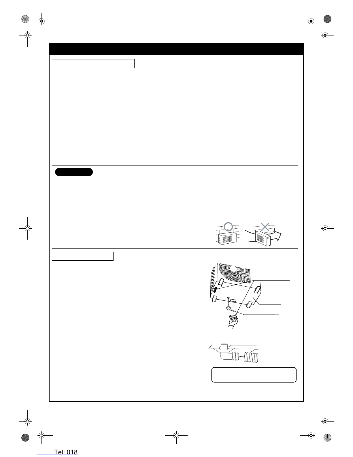
12
FR
• Un endroit qui procure un espace suffisant autour de l’unité extérieure comme illustré sur le schéma.
• Un endroit qui peut supporter le poids de l’unité extérieure et n’augmente pas le niveau de bruit et les vibrations.
• Un endroit où le bruit de fonctionnement et l’air déchargé ne gênent pas les voisins.
• Un endroit qui n’est pas exposé à un vent violent.
• Un endroit sans gaz combustibles.
• Un endroit qui ne bloque pas un passage.
• Lorsque l’unité extérieure doit être installée en position élevée, assurez-vous de fixer ses pieds.
• Ce climatiseur accepte une longueur de tuyauterie de raccordement de 2 m à 25 m.
• Il est inutile d’ajouter du fluide frigorigène si la longueur de la tuyauterie de raccordement est de 15 m ou moins.
• Vous devrez ajouter 20 g de fluide frigorigène par mètre de tuyauterie de raccordement ajoutée si l’installation nécessite une
tuyauterie de 16 m à 25 m.
• Le niveau de hauteur admissible est de jusqu’à 10 m.
• Un endroit où l’eau évacuée ne pose pas de problème.
Précautions lors de l’ajout de fluide frigorigène
• Utilisez une balance ayant une précision d’au moins 10 g par ligne indicatrice lors de l’ajout de fluide frigorigène.
• Utilisez un fluide frigorigène pour faire l’appoint de réfrigérant. Le réfrigérant étant sous forme liquide, il peut couler rapidement.
Effectuez l’opération de remplissage avec précautions en versant le fluide frigorigène graduellement.
• Des orifices sont prévus sur le panneau inférieur de l’unité extérieure pour
garantir que l’eau de dégivrage produite pendant les opérations de chauffage
est évacuée efficacement. Si une évacuation centralisée est nécessaire lors de
l’installation de l’unité sur un balcon ou un mur, effectuez les opérations cidessous pour évacuer l’eau.
1. Procédez aux travaux d’étanchéité en installant les capuchons en caoutchouc
étanches
i dans les 2 orifices allongés sur le panneau inférieur de l’unité
extérieure.
[Comment installer les capuchons en caoutchouc étanches]
1) Placez quatre doigts dans chaque capuchon et introduisez les capuchons
dans les orifices d’évacuation d’eau en les poussant en place depuis le
dessous du panneau inférieur.
2) Appuyez sur les circonférences extérieures des capuchons pour garantir
qu’ils sont bien introduits en place.
(Des fuites d’eau peuvent se produire si les capuchons ne sont pas
introduits correctement, si leurs circonférences extérieures se soulèvent
ou si les capuchons se prennent ou se coincent sur quelque chose.)
2. Installez l’embout d’évacuation
h et un flexible d’évacuation en vente dans le
commerce (ayant un diamètre intérieur de 16 mm) et évacuez l’eau.
(Reportez-vous au schéma d’installation des unités intérieure et extérieure
pour la position où l’embout d’évacuation
h est installé.)
• Vérifiez que l’unité extérieure est horizontale et acheminez le flexible
d’évacuation à un angle incliné vers le bas avec très peu de jeu dans le flexible.
5 INSTALLATION DE L’UNITE EXTERIEURE
Emplacement d’installation
ATTENTION
1. Installez l’unité extérieure dans un endroit où il n’y a pas d’obstruction près de sa prise d’air ou sortie d’air.
2. Lorsque l’unité extérieure est installée dans un endroit toujours exposé à des vents forts comme au bord de la mer ou à un
étage en hauteur, assurez le fonctionnement normal du ventilateur au moyen d’un conduit ou d’un bouclier coupe vent.
3. Dans les régions de grand vent, installez l’unité de manière à empêcher l’admission de vent.
4. Une installation dans les endroits suivants peut provoquer des problèmes. N’installez pas l’unité dans de tels endroits.
• Un endroit souillé d’huile de machine.
• Un endroit salin comme au bord de la mer.
• Un endroit où l’air est chargé de gaz sulfuré.
• Un endroit où des ondes à haute fréquence peuvent être émises, par
des équipements audio, des machines à souder ou des équipements
médicaux.
Evacuation de l’eau
Ven t
violent
i Capuchons en
caoutchouc étanches
(fournis avec l’unité
extér ieure)
h Embout d’évacuation
Panneau inférieur
Flexible d’évacuation en
vente dans le commerce
N’utilisez pas de flexible de jardin ordinaire qui peut
s’aplatir et empêcher l’évacuation.
h Embout d’évacuation
Panneau
inférieur
02_Installation_FR.fm Page 12 Tuesday, January 9, 2007 12:33 PM
Heronhill - for all your Toshiba requirements
Tel: 01823 665660
www.heronhill.co.uk
Fax: 01823 665807
 Loading...