

Page 1
SERVICE MANUAL
AIR CONDITIONER
RAS-24SKP-ES2 / RAS-24SA-ES2
RAS-24SKHP-ES2 / RAS-24S2AH-ES2
FILE NO. SVM-10049
SPLIT WALL TYPE
April, 2010
Page 2

CONTENTS
1. SPECIFICATIONS
2. CONSTRUCTION VIEWS
2-1 Indoor Unit
2-2 Outdoor Unit
3. WIRING DIAGRAM
3-1 RAS-24SKP-ES2 / RAS-24SA-ES2
3-2 RAS-24SKHP-ES2 / RAS-24S2AH-ES2
4. SPECIFICATION OF ELECTRICAL PARTS
4-1 Indoor Unit (RAS-24SKP-ES2)
Outdoor Unit (RAS-24SA-ES2)
4-2
4-3
Indoor Unit (RASP-24SKHP-ES2)
Outdoor Unit (RAS-24S2AH-ES2)
4-4
5. REFRIGERATION CYCLE DIAGRAM
FILE NO. SVM-10049
RAS-24SKP-ES2 / RAS-24SA-ES2
5-1
RAS-24SKHP-ES2 / RAS-24S2AH-ES2
5-2
6. CONTROL BLOCK DIAGRAM
6-1 RAS-24SKP-ES / RAS-24SA-ES2
6-2 RAS-24SKHP-ES2 / RAS-24S2AH-ES2
7. OPERATION DESCRIPTION
7-1 Remote control
7-2 Outline of Air Conditioner Control
7-3 Description of Operation Circuit
7-4 Description of Safety and Reliability Prevention Function
7-5 One-Touch Operation
7-6 Hi POWER Operation
7-7 QUIET Operation
7-8 ECO Operation
7-9 COMFORT SLEEP Operation
7-10 FILTER Check lamp
7-11 Auto Restart Function
7-12 Self-Cleaning Operation
– 1 –
Page 3

8. INSTALLATION PROCEDURE
8-1 Safety Cautions
8-2 Installation Diagram of Indoor and Outdoor Units
8-3 Installation
8-4 Indoor Unit
8-5 Outdoor Unit
8-6 Test Operation
9. TROUBLESHOOTING CHART
9-1 Troubleshooting Procedure
9-2 Basic Check Items
9-3 Primary Judgement
9-4 Self-Diagnosis by Remote Control (Check Code)
9-5 How To Diagnose Faulty Parts
Troubleshooting for Indoor unit
9-6
9-7 Troubleshooting for Wiring (Interconnect cable and Serial Signal Wire)
9-8 Troubleshooting for P.C. Board
9-9 Troubleshooting for Remote Control
FILE NO. SVM-10049
HOW TO REPLACE THE MAIN PARTS
10.
10-1 Indoor Unit
Outdoor Unit
10-2
11. EXPLODED VIEWS AND PARTS LIST
11-1 Indoor Unit (E - Parts Assy)
11-2 Indoor Unit
11-3
Outdoor Unit (RAS-24SA-ES2)
11-4
Outdoor Unit (RAS-24S2AH-ES2)
− 2 −
Page 4
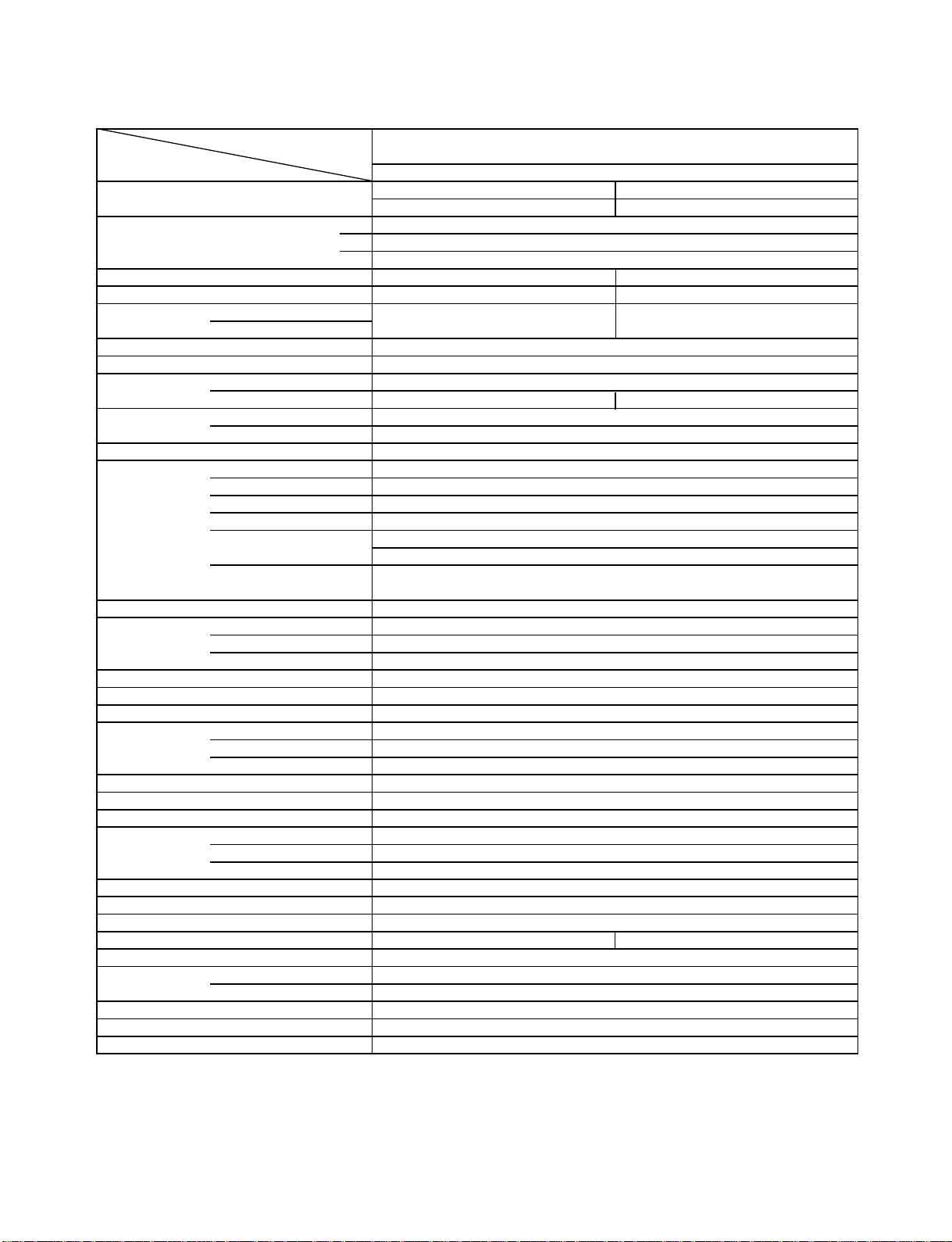
1. SPECIFICATIONS
MODEL RAS-24SKP-ES2
Cooling
ITEM
Capacity
kW
Phase
Power source
Hz
Power consumption W
Power factor %
Running A
Current Indoor/Outdoor
Starting current A
Moisture removal lit/h
Noise Indoor (H/M+/M/L+/L) dB
Outdoor (220-240V) dB
Refrigerant Name of refrigerant
Rated amount kg
Refrigerant control
Interconnection Gas side size mm
pipe Connection type
Liquid side size mm
Connection type
Maximum length m
(One way)
Maximum height m
difference
INDOOR UNIT
Dimensions Height mm
Width mm
Depth mm
Net weight kg
Evaporator type
Indoor fan type
Airflow volume High fan
Medium fan
Low fan
3
m
3
m
3
m
Fan motor output W
Air filter
OUTDOOR UNIT
Dimensions Height mm
Width mm
Depth mm
Net weight kg
Condenser type
Outdoor fan type
Airflow volume
3
m
Fan motor output W
Compressor Model
Output W
Safety device
Louver type
Usable outdoor temperature range °C
Note *1 Chargeless pipe
*2 Maximum pipe
V
/h
/h
/h
/h
220V
6.80
2030
98
0.3/9.1 0.3/8.6
56
Honeycomb woven filter with PP frame
4000
FILE NO. SVM-10049
RAS--24SA-ES2
1∅
220 - 240
50
55
2.7
50/48/46/43/40
R410A
1.90
Capillary tube
∅12.7
Flare connection
∅6.35
Flare connection
RAS-24SKP-ES2
RAS-24SA-ES2
PA271X3CS-4MUL
Automatic louver
1
15*
2
25*
10
320
1050
228
13
Finned tube
Cross flow fan
1240
1000
850
30
890
900
320
59
Finned tube
Propeller fan
85
2000
Fuse , IOL
15 ~ 43
240V
6.85
2070
97
57
4200
− 3 −
Page 5
FILE NO. SVM-10049
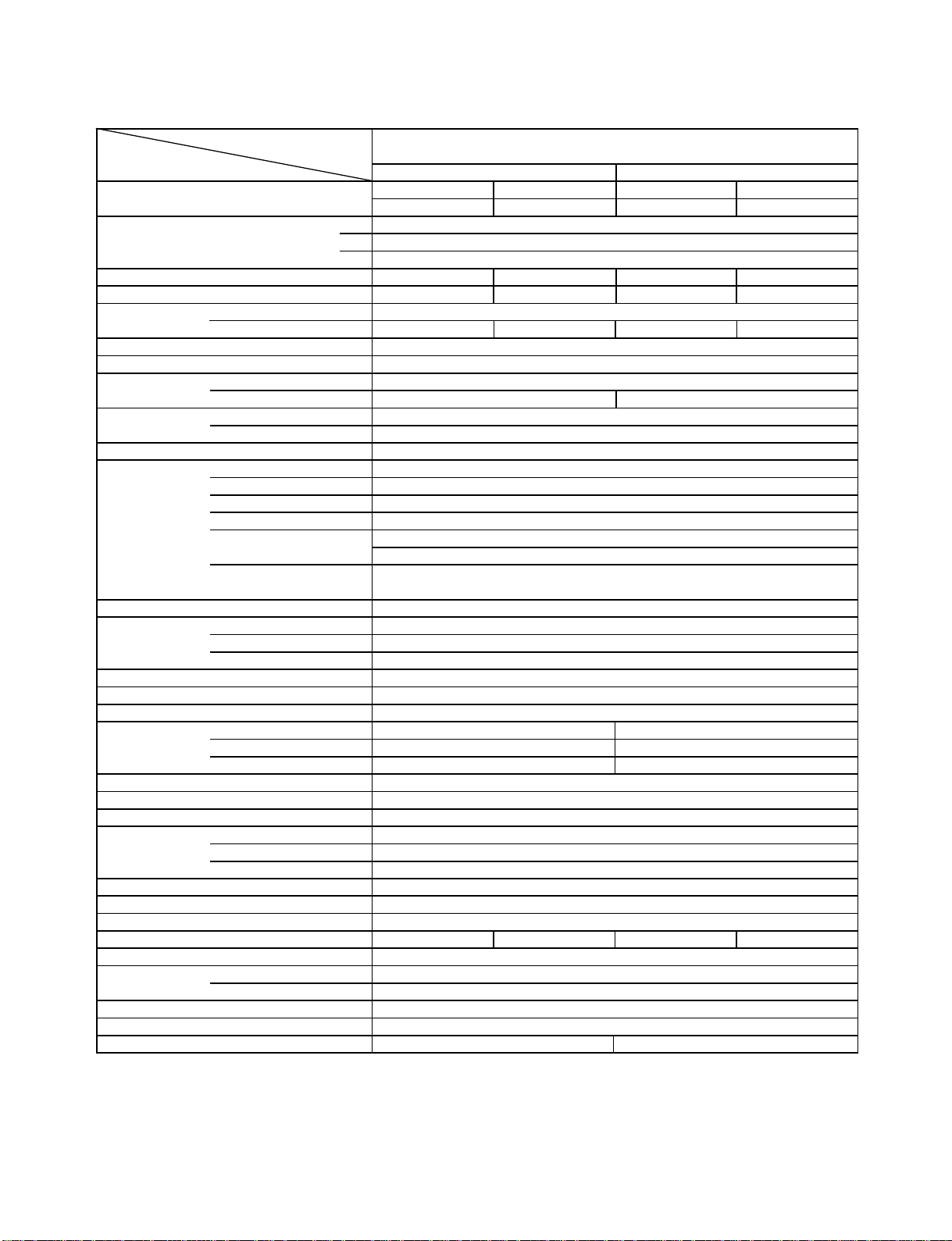
MODEL RAS-24SKHP-ES2
RAS-24S2AH-ES2
ITEM Cooling Heating
Capacity
kW
220V
6.78
Phase
Power source
V
Hz
Power consumption W
Power factor %
2030
98 96
Running Indoor A 0.30
Current Outdoor A 9.40 9.10 8.95 8.90
Starting current A
Moisture removal lit/h
Noise Indoor (H/M+/M/L+/L) dB
Outdoor (220-240V) dB
56-57
Refrigerant Name of refrigerant
Rated amount kg
Refrigerant control
Interconnection Gas side size mm
pipe Connection type
Liquid side size mm
Connection type
Maximum length m
(One way)
Maximum height m
difference
INDOOR UNIT
Dimensions Height mm
Width mm
Depth mm
Net weight kg
Evaporator type
Indoor fan type
Airflow volume High fan
Medium fan
Low fan
3
m
/h
3
/h
m
3
m
/h
1240
1000
Fan motor output W
Air filter
OUTDOOR UNIT
Dimensions Height mm
Width mm
Depth mm
Net weight kg
Condenser type
Outdoor fan type
Airflow volume
3
m
/h
4000 4200 4000
Fan motor output W
Compressor Model
Output W
Safety device
Louver type
Usable outdoor temperature range °C
15 ~ 43 -10 ~ 24
Note *1 Chargeless pipe
*2 Maximum pipe
240V 220V
6.82 7.28
1∅
220 - 240
50
2100 1930
98
55
2.7
50/48/46/43/40
R410A
2.00
Capillary tube
∅12.7
Flare connection
∅6.35
Flare connection
1
15*
2
25*
10
RAS-24SKHP-ES2
320
1050
228
14
Finned tube
Cross flow fan
30
Honeycomb woven filter with PP frame
RAS-24S2AH-ES2
890
900
320
64
Finned tube
Propeller fan
85
PA271X3CS-4MUL
2000
Fuse , IOL
Automatic louver
240V
7.32
2050
96
57-58
1240
1000
850850
4200
− 4 −
Page 6
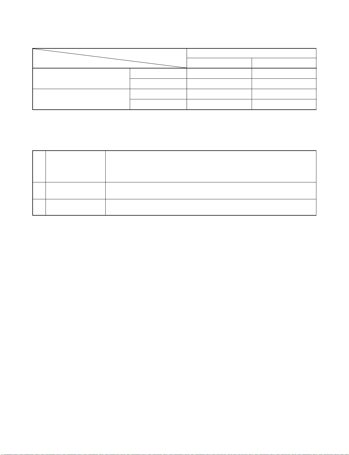
Note : 1
• Capacity is based on the following temperature conditions.
FILE NO. SVM-10049
Condition
Temperature
(DB) 27°C20°C
Indoor unit inlet air temperature
(WB) 19°C15°C
(DB) 35°C7°C
Outdoor unit inlet air temperature
(WB) 24°C6°C
Note : 2
• Charge refrigerant according to the table below.
Refrige rant
*1 No need to charge
extra refrigerant
*2 Need to charge
extra refrigerant
JIS C9612
Cooling Heating
RAS-24SKP-ES2 / RAS-24SA-ES2
RAS-24SKHP-ES2 / RAS-24S2AH-ES2
15 m or less
Over 15 m up to 25 m (20 g/m)
– 5 –
Page 7
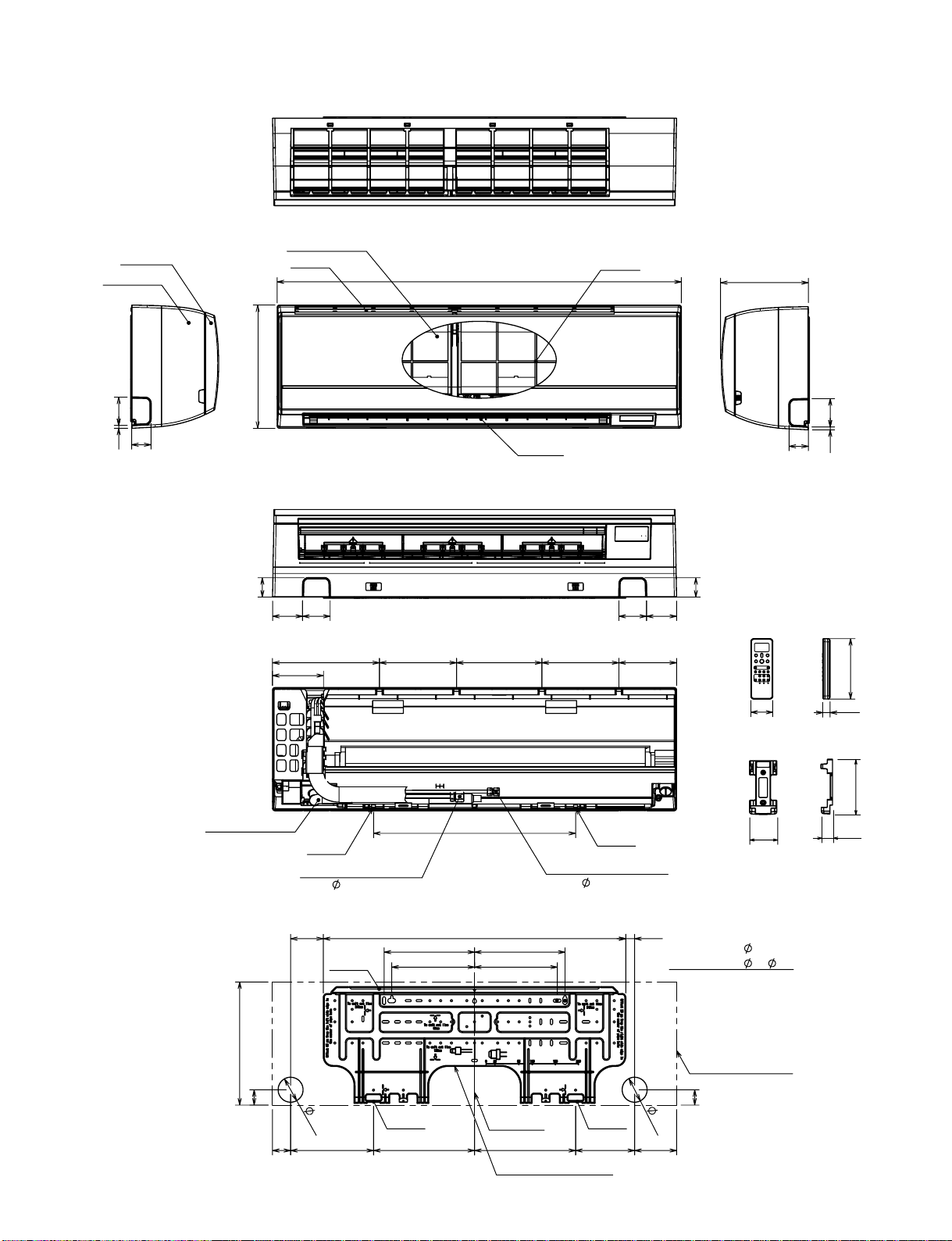
2-1. Indoor Unit
FILE NO. SVM-10049
2. CONSTRUCTION VIEWS
Grille Inlet
Front Panel
73.57
50
Knock out system
Heat exchanger
320
50
78 72
Air inlet
278 200 222 150
132
1050
Air outlet
200
Air filter
72 78
50
228
50
Knock out system
73.5
7
157
Drain hose (0.5m)
320
40
525
Hanger
Connecting pipe (0.39m)
12.70)
(Flare
85 23
Hanger
6
5
Hanger Hanger
262.5
786
235
215
Center line
Installation plate outline
Connecting pipe (0.49m)
235
215
262.5
Hanger
6.35)(Flare
For stud bold (
For stud bold (
6
5
10947 215.5 153.5
56
Wireless remote controller
63
Remote controller holder
6)
8~
10)
Outline of indoor unit
40
19
125
26
− 6 −
Page 8
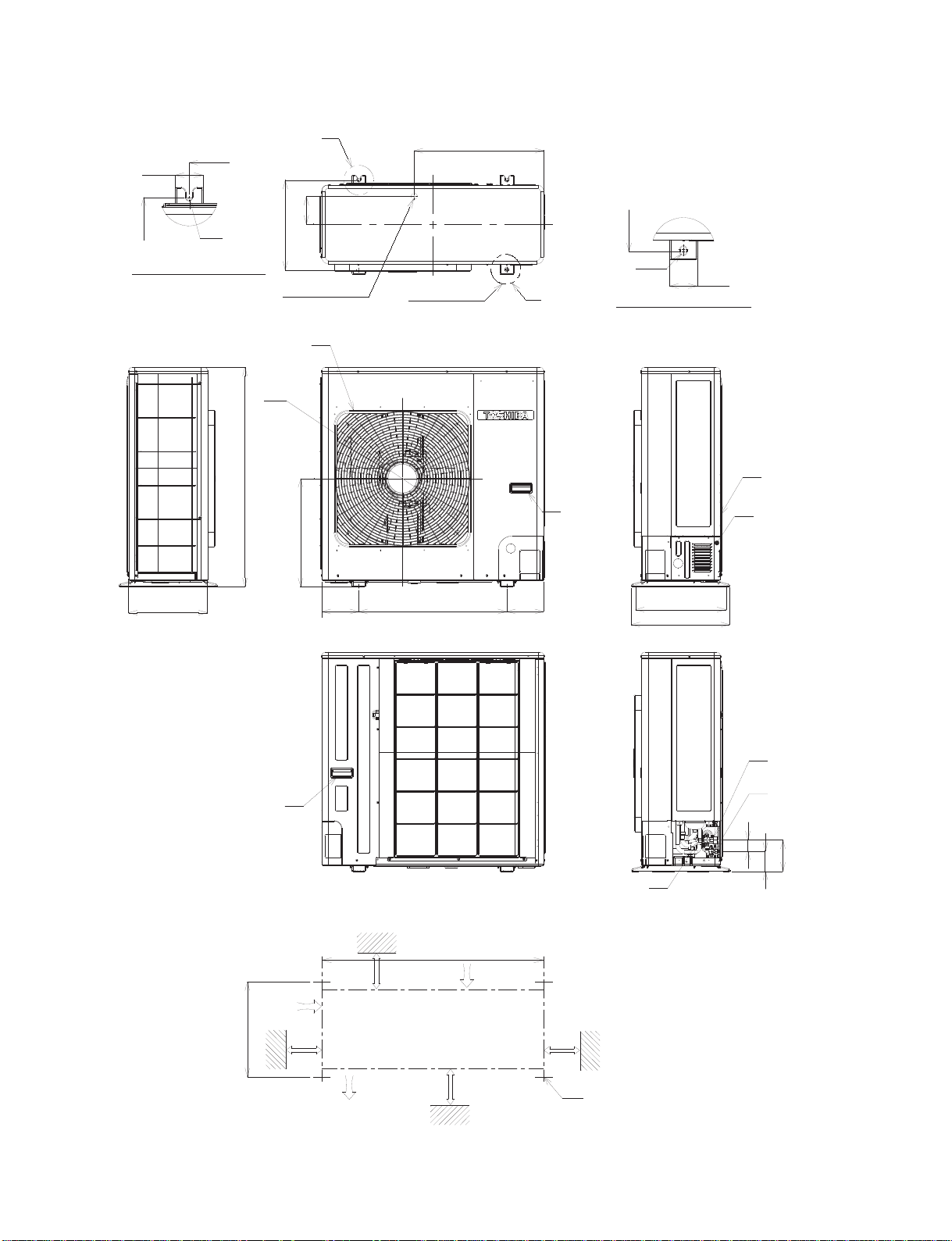
2-2. Outdoor Unit
FILE NO. SVM-10049
56.5
365
A Detail Drawing (Back leg)
600
R6
FAN-GUARD
890
365
Ø
547
Ø
A
113
25 Drain outlet
438
2- 12x17 Hole
Ø
525
365
12x17 Hole
Ø
B
HANDLE
B Detail Drawing (Front leg)
56.5
Z
PANEL-PIPING-BK
320
HANDLE
200 or more
320
150
Z View
600
Air inlet
150600
Service port
600 or more
365
400
Gas-side
(Flare 12.70)
Liquid-side
(Flare 6.35)
45
128
82
Ø
Ø
150 or more
Air outlet
1000 or more
Installation dimension
– 7 –
4x 17 Long holes
Ø
Page 9
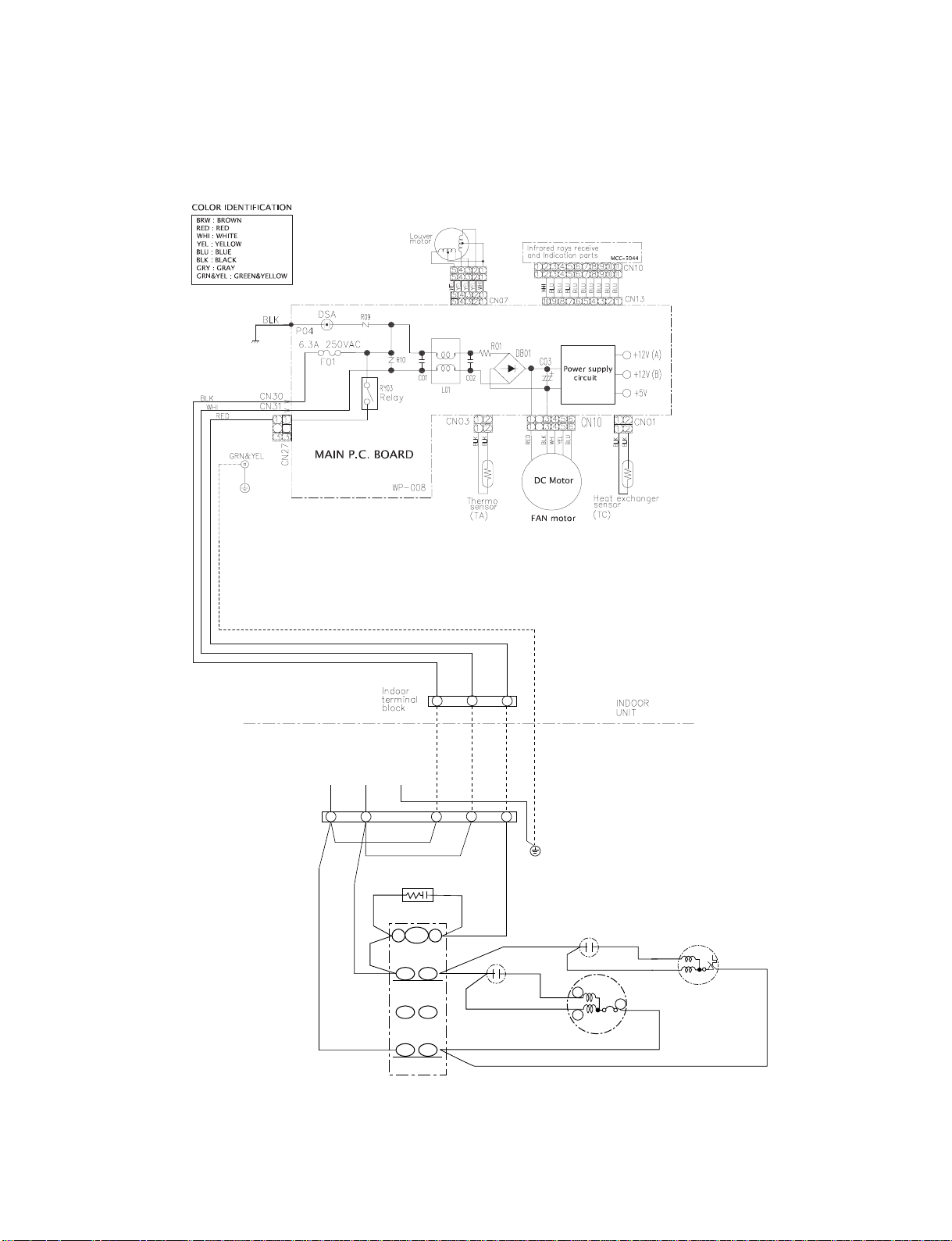
3. WIRING DIAGRAM
3-1. RAS-24SKP-ES2 / RAS-24SA-ES2
FILE NO. SVM-10049
OUTDOOR
TERMINAL
BLOCK
POWER SUPPLY
220 − 240 V ~ 50 Hz
L
N
BLK
RED
BLK
RED
RED
MAGNETIC CONTACTOR
1
1
BLK BLK
SPARK KILLER
A2 A1
52C
1/L1 2/T1
6/T35/L3
2
2
RED
CAPACITOR
3
3
GRY
CHASSIS
RED
WHI
PNK
COMPRESSOR
CAPACITOR
S
R
OUTDOOR
UNIT
BLK
C
WHI
RED
FAN MOTOR
BLK
– 8 –
Page 10
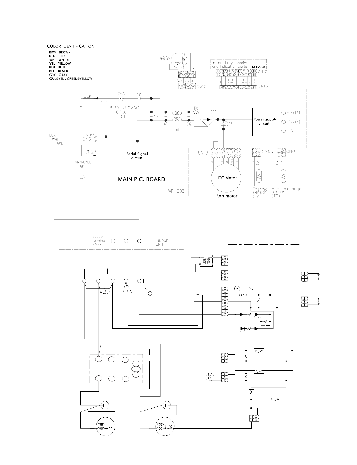
3-2. RAS-24SKHP-ES2 / RAS-24S2AH-ES2
FILE NO. SVM-10049
OUTDOOR
TERMINAL
BLOCK
POWER SUPPLY
220- 240 V ~ 50 Hz
L
BLK
RED
BLK
RED
WHI
PNK
COMPRESSOR
2
1
3
GRN&YEL
2
5/L3
3
i
CHASSIS
A1
N
FERRITE CORE
RED
CONTACTOR
1/L1
1
MAGNETIC
52C
BLK
6/T3
A2
RED
WHI
RED
FAN MOTOR
2/T1
CAPACITOR CAPACITOR
S
C
R
TRANSFORMER
OUTDOOR
UNIT
BLK BLK
BLK
BLK
RED
RED
BLK
BLK
WHI
RED
GRY
BLU
YEL
BLU
BLU
COIL FOR
4 WAY VALVE
MAIN P.C. BOARD (MCC-890)
1
1
2
CN06
3
3
1
1
CN05
3
3
SG01
1
1
F01
3
3
250VAC T6. 3A
5
5
CN01
7
7
9
9
1
CN11
313
11
33
CR11
CN02
CR12
CR13
TNR
R74
CN03
1
1
RY07
RY05
3
TNR
R73
RY06
CN07
CN08
DISCHARGE
PIPE
SENSOR (TD)
BLU
1
1
2
3
3
BLU
BLK
1
1
2
3
3
BLK
HEAT
EXCHANGER
SENSOR (TE)
– 9 –
Page 11
4. SPECIFICATION OF ELECTRICAL PARTS
4-1. Indoor Unit (RAS-24SKP-ES2)
FILE NO. SVM-10049
No.
1 Fan motor (for indoor) MF-340-30-1RT DC 340V, 30W
2 Thermo sensor (TA-sensor) ——— 10 kΩ at 25°C
3 Switching Transformer (T01) SWT-77 DC7V, 12 V
4 Microcontroller TMP87CM40ANG-6P68
5 Heat exchanger sensor
(TC-sensor)
6 Line filter (L01) LC*SS11V-R06270 27mH, 600mA
7 Diode (DB01) D3SBA60 4 A, 600 V
8 Capacitor (C03) EKMH451VSN121MQ35S 120 µF, 450 V
9 Fuse (F01) BET6.3A 6.3 A, 250 V
10 Varistor (R09, R10) SR561K14DO 560 V
11 Resistor (R01) RF-5TK1R8
2 TLou
13
v
Relay : (RY03)
P5War1ts name
er motor MP24Z3T Output (Rated) 2 W, 16 poles, 4 phase,
ype
——— 10 kΩ at 25°C
1.8Ω ,
DC 12 V
G5NB-1A-CA
Coil DC 12V, 16.7mA, Contact AC 250V, 3A
Specifications
4-2. Outdoor Unit (RAS-24SA-ES2)
No. Parts name Type Specifications
Output (Rated) 2000W, 2poles, 1 phase, 220-240V 50Hz
1 Compressor PA271X3CS-4MU2 Winding resistance (Ω ) Red-Black White-Black
(at 20°C) 1.27 2.10
Output (Rated) 42W, 4poles, 1 phase, 220 − 240V, 50Hz
2 Fan motor (for outdoor) WLF-240-85A Winding resistance (Ω) Red-Black White-Black
(at 20° C) 70.5 120.1
Running capacitor
3
(for fan motor)
Running capacitor
4
(for compressor)
5
Magnetic contactor
DS451355NPQB AC 450V, 3.0µ F
32332I5606J063 A
B
A35P 220-240V, 50Hz
C 450V, 60µ F
– 10 –
Page 12
FILE NO. SVM-10049
4-3. Indoor Unit (RAS-24SKHP-ES2)
No. Parts name Type Specifications
1 Fan motor (for indoor) MF-340-30-1RT DC 340V, 30W
2 Thermo sensor (TA-sensor) ——— 10 kΩ at 25°C
3 Switching Transformer (T01) SWT-77 DC 7V, 12V
4 Microcontroller TMP87CM40ANG-6P68
5 Heat exchanger sensor
(TC-sensor)
6 Line filter (L01) LC*SS11V-R06270 27mH, 600mA
7 Diode (DB01) D3SBA60 4 A, 600 V
8 Capacitor (C03) EKMH451VSN121MQ35S 120 µF, 450 V
9 Fuse (F01) BET6.3A 6.3 A, 250 V
10 Varistor (R09, R10) SR561K14DO 560 V
11 Resistor (R01) RF-5TK1R8 1.8Ω , 5W
12 Louver motor MP24Z3T Output (Rated) 2 W, 16 poles, 4 phase,
——— 10 kΩ at 25°C
DC 12 V
4-4. Outdoor Unit (RAS-24S2AH-ES2)
No. Parts name Type Specifications
Output (Rated) 2000W, 2poles, 1 phase, 220 − 240V, 50Hz
1 Compressor PA271X3CS-4MU2 Winding resistance (Ω) Red-Black White-Black
(at 20°C) 1.27 2.10
Output (Rated) 42W, 4poles, 1 phase, 220 – 240V, 50Hz
2 Fan motor (for outdoor) FG-240-42A-1 Winding resistance (Ω) Red-Black White-Black
(at 20°C) 70.5 120.1
Running capacitor
3
(for fan motor)
Running capacitor
4
(for compressor)
Solenoid coil
5
(for 4-way valve)
6 Thermo sensor TE / TD 10kΩ at 25°C / 50kΩ at 25°C
7 Magnetic contactor A35P 220 ~ 240V, 50Hz
8 Transformer TT-05 220 ~ 240V
9 Microcontroller TMP47C840N
10 Varistor (R73, R74) 15G471K 470V
11 Fuse (F01) TSCR T6.3A, 250V
DS451305NPQB AC 450V, 3.0µF
B32332I5606J063 AC 450V, 60µF
VHV (STF) AC 220 ~ 240V
– 11 –
Page 13
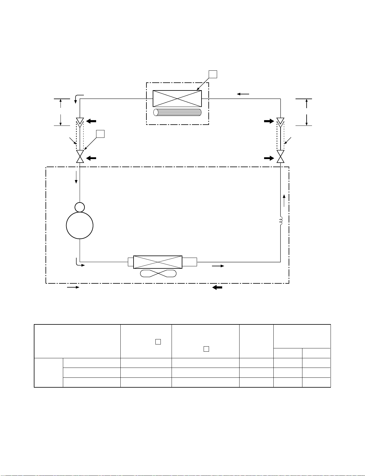
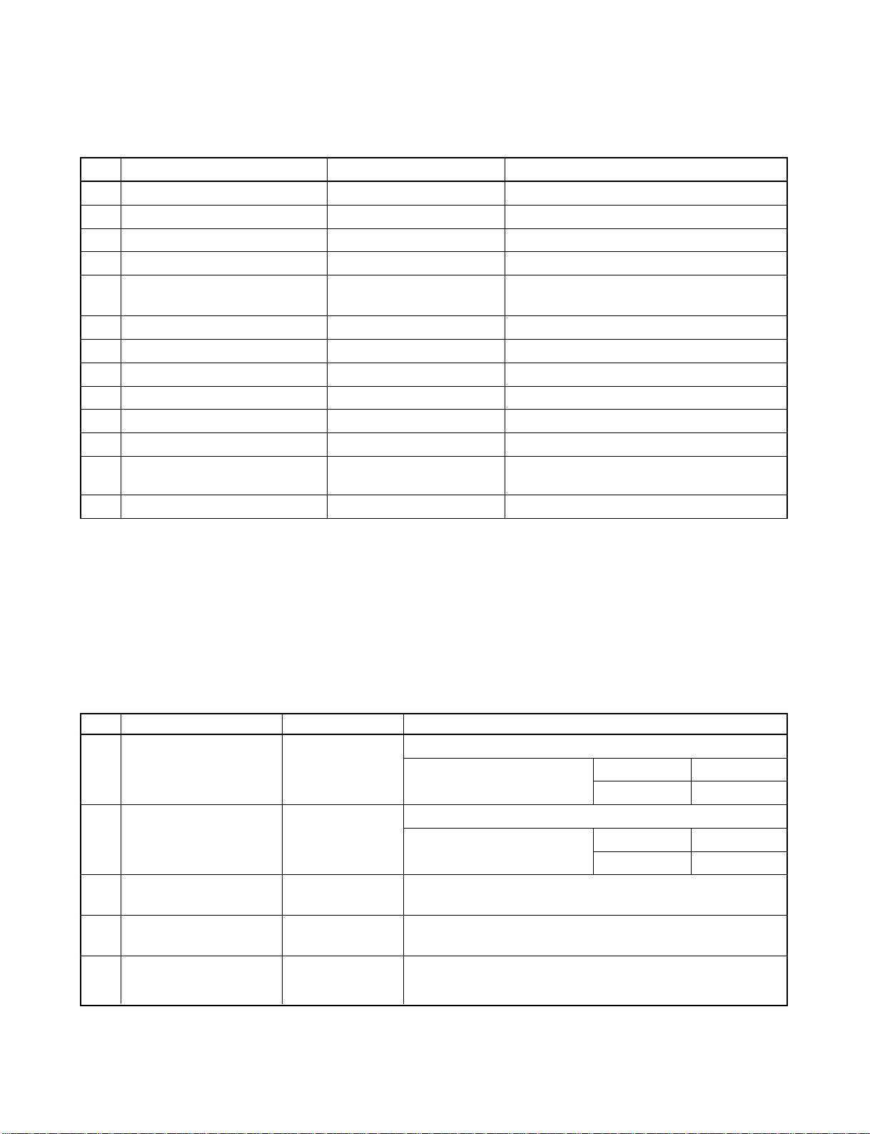
5. REFRIGERATION CYCLE DIAGRAM
5-1. RAS-24SKP-ES2 / RAS-24SA-ES2
FILE NO. SVM-10049
Indoor unit
Cooling
0.39 m
(Connecting pipe)
∅
12.7
O.D.:12.7 mm O.D.:6.35 mm
Cooling
Compressor
P
Packed valve
(∅12.7 )
Gas container connection (Reinstall etc.)
PA271X3CS-4MUL
Heat exchanger
Cross flow fan
T
0.49 m
(Connecting pipe)
∅
6 .35
Packed valve
(∅6.35)
Capillary tube
450 s
∅2.0x
Heat exchanger
Refrigerant
R410A 1.90 kg
Cooling
Propeller fan
Outdoor unit
Mark ( ) means check points of Gas Leak
Ambient temp.
50 Hz
Standard
pressure
(MPaG)
P
Surface temp. of heat
exchanger interchanging
pipe
T
(°C)
Fan speed
(indoor)
conditions DB/WB
(°C)
Indoor Outdoor
Standard 0.86 9.4 High 27/19 35/24
Cooling High temperature 1.03 14.3 High 32/23 43/26
Low temperature 0.65 1.9 Low 21/15 21/15
Note : Measure the heat exchanger temperature at the center of U-bend. (By means of TC sensor.)
– 12 –
Page 14
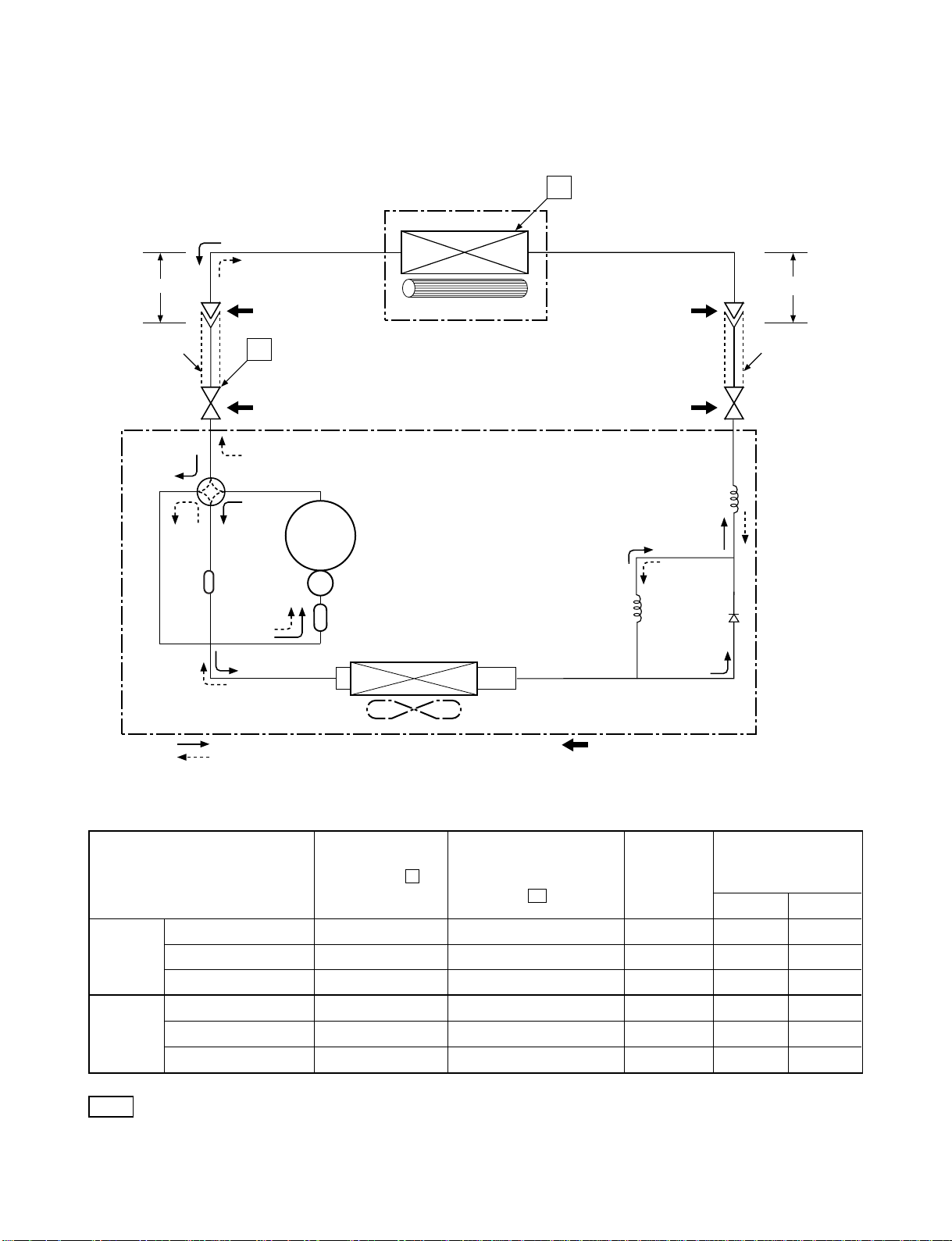
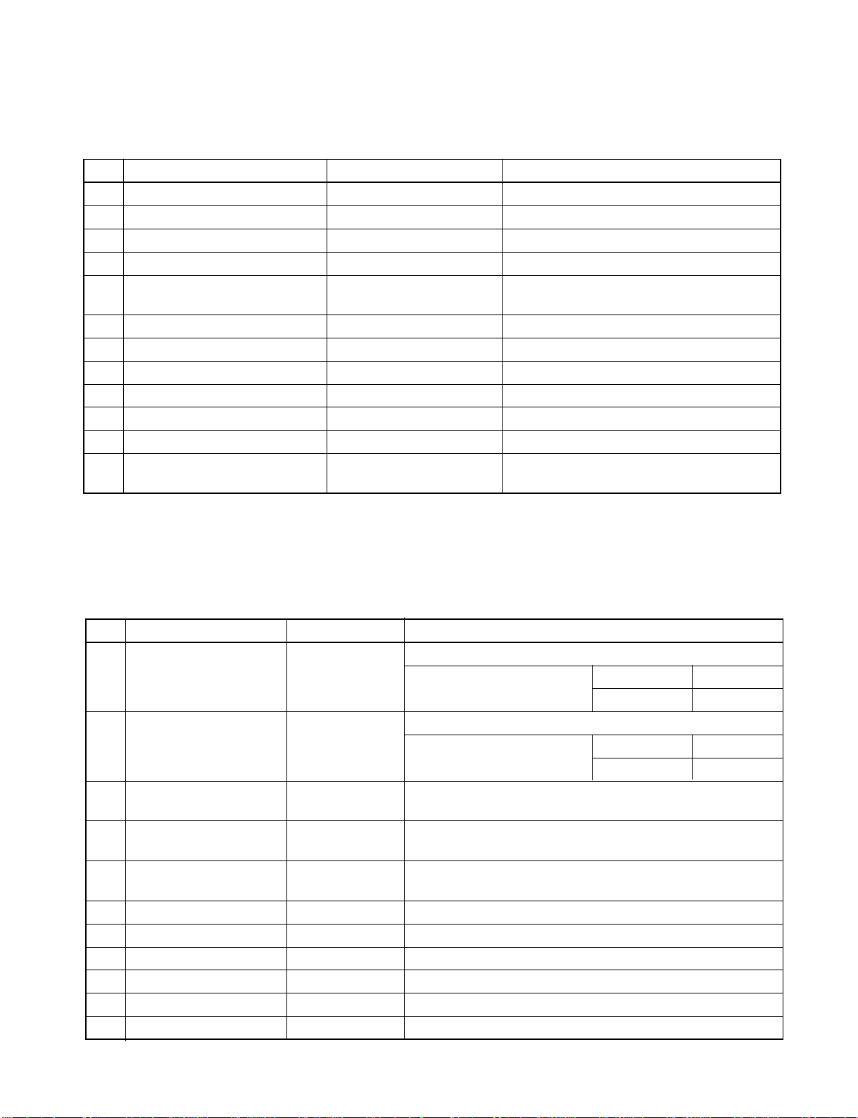
5-2. RAS-24SKHP-ES2 / RAS-24S2AH-ES2
FILE NO. SVM-10049
Indoor unit
Cooling
0.39 m
(Connecting pipe)
Æ12.7
O.D.:12.7 mm O.D.:6.35 mm
Cooling
Heating
Heating
P
Packed valve
(Æ12.7)
Heating
4-way valve
Cooling
Discharge Muffler
∅
25x160L
Compressor
Accumulator
PA271X3CS-4MUL
Heat exchanger
Cross flow fan
T1
Capillary tube
Æ2.0 x 700
Packed valve
(Æ6.35)
Capillary tube
Æ2.0 x 450
l
0.49 m
(Connecting pipe)
Æ6.35
l
Heat exchanger
Refrigerant
R410A 2.00 kg.
Cooling
Heating
Propeller fan
Outdoor unit
Mark ( ) means check points of Gas Leak.
Ambient temp.
50Hz
Standard
pressure
(MPaG)
P
Surface temp. of heat
exchanger interchanging
pipe
T1
(°C)
Fan speed
(indoor)
conditions DB/WB
(°C)
Indoor Outdoor
Standard 2.64 44.7 High 20/15 7/6
Heating Overload*1 3.54 ~ 3.80 49.3 ~ 51.0 Low 27/- 24/18
Low temperature 2.28 30.3 High 20/
-
-10/-10
Standard 0.90 11.6 High 27/19 35/24
Cooling Overload 1.10 17.5 High 32/23 43/26
Low temperature 0.73 2.6 Low 21/15 21/15
Note
Measure the heat exchanger temperature at the center of U-bend. (By means of TC sensor)
·
·
*1 During heating overload operation, a value for the high temperature limit control operation is included.
- 13 -
Page 15
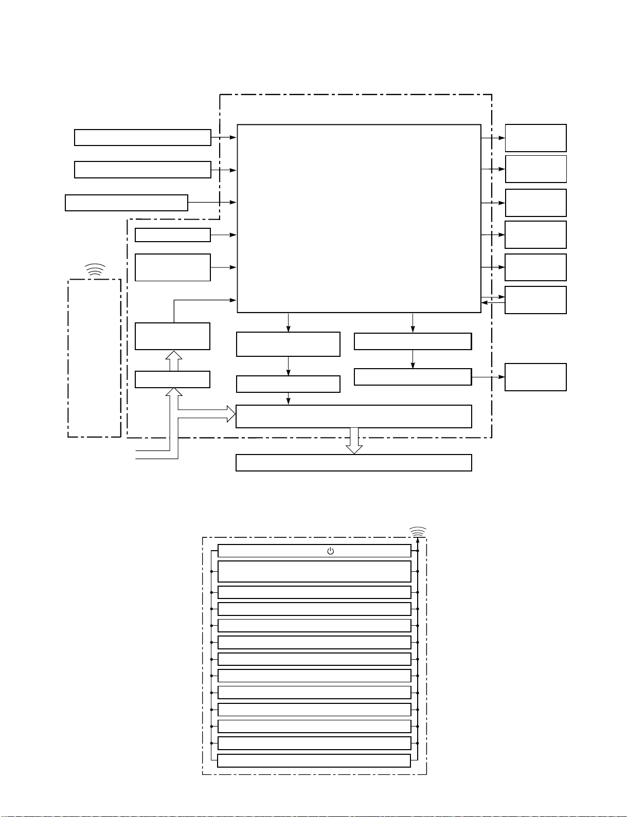
6. CONTROL BLOCK DIAGRAM
6.1 RAS-24SKP-ES2 / RAS-24SA-ES2
Indoor Unit Control Panel
Heat Exchanger Sensor
Functions
• Louver Control
FILE NO. SVM-10049
M.C.U.
Operation
Display
Temperature Sensor
Infrared Rays Signal Receiver
Initiallizing Circuit
Infrared
Rays
Remote
Control
From Outdoor Unit
240 V AC 50 Hz
Clock Frequency
Oscillator Circuit
Power Supply
Circuit
Noise Filter
• 3-minute Delay at Restart for Compressor
• Motor Revolution Control
• Processing
(Temperature Processing)
• Timer
Outdoor unit
ON/OFF Signal
Relay Driver
Relay RY03
Outdoor Unit
Louver ON/OFF Signal
Louver Driver
Timer
Display
Filter Sign
Display
Fan Only
Sign Display
Hi Power
Sign Display
Indoor
Fan Motor
Louver Motor
REMOTE CONTROL
Infrared Rays
Remote Control
Operation ( )Operation ( )
Operation Mode Selection
AUTO, COOL, DRY, FAN ONLY
Temperature Setting
Fan Speed Selection
ON TIMER Setting
OFF TIMER Setting
Louver Auto Swing
Louver Direction Setting
ECO
Hi power
TIMER 1.3.5.9H
COMFORT SLEEP
QUIET
– 14 –
Page 16
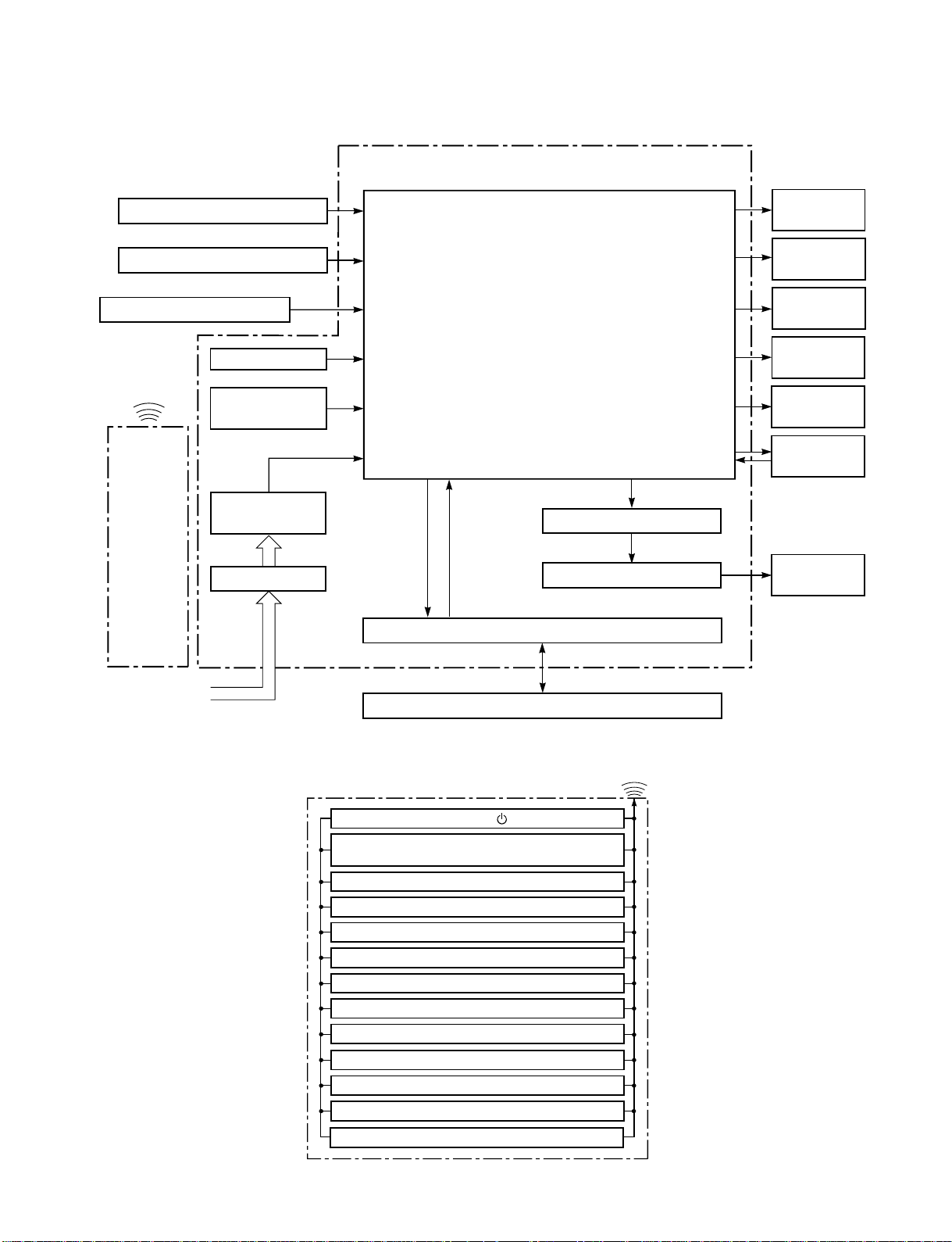
6.2 RAS-24SKHP-ES2 / RAS-24S2AH-ES2
Indoor Unit Control Panel
Heat Exchanger Sensor
Functions
• Louver Control
FILE NO. SVM-10049
M.C.U.
Operation
Display
Temperature Sensor
Infrared Rays Signal Receiver
Initiallizing Circuit
Infrared
Rays
Remote
Control
From Outdoor Unit
240 V AC 50 Hz
Clock Frequency
Oscillator Circuit
Power Supply
Circuit
Noise Filter
• 3-minute Delay at Restart for Compressor
• Motor Revolution Control
• Processing
(Temperature Processing)
• Timer
• Serial Signal Communication
Louver ON/OFF Signal
Louver Driver
Serial Signal Transmitter/Receiver
Serial Signal Communication
Timer
Display
Filter Sign
Display
PRE DEF.
Sign Display
Hi Power
Sign Display
Indoor
Fan Motor
Louver Motor
REMOTE CONTROL
Infrared Rays
Remote Control
Operation ( )Operation ( )
Operation Mode Selection
AUTO, COOL, DRY, HEAT, FAN ONLY
Temperature Setting
Fan Speed Selection
ON TIMER Setting
OFF TIMER Setting
Louver Auto Swing
Louver Direction Setting
ECO
Hi power
TIMER 1.3.5.9H
COMFORT SLEEP
QUIET
– 15 –
Page 17
7. OPERATION DESCRIPTION
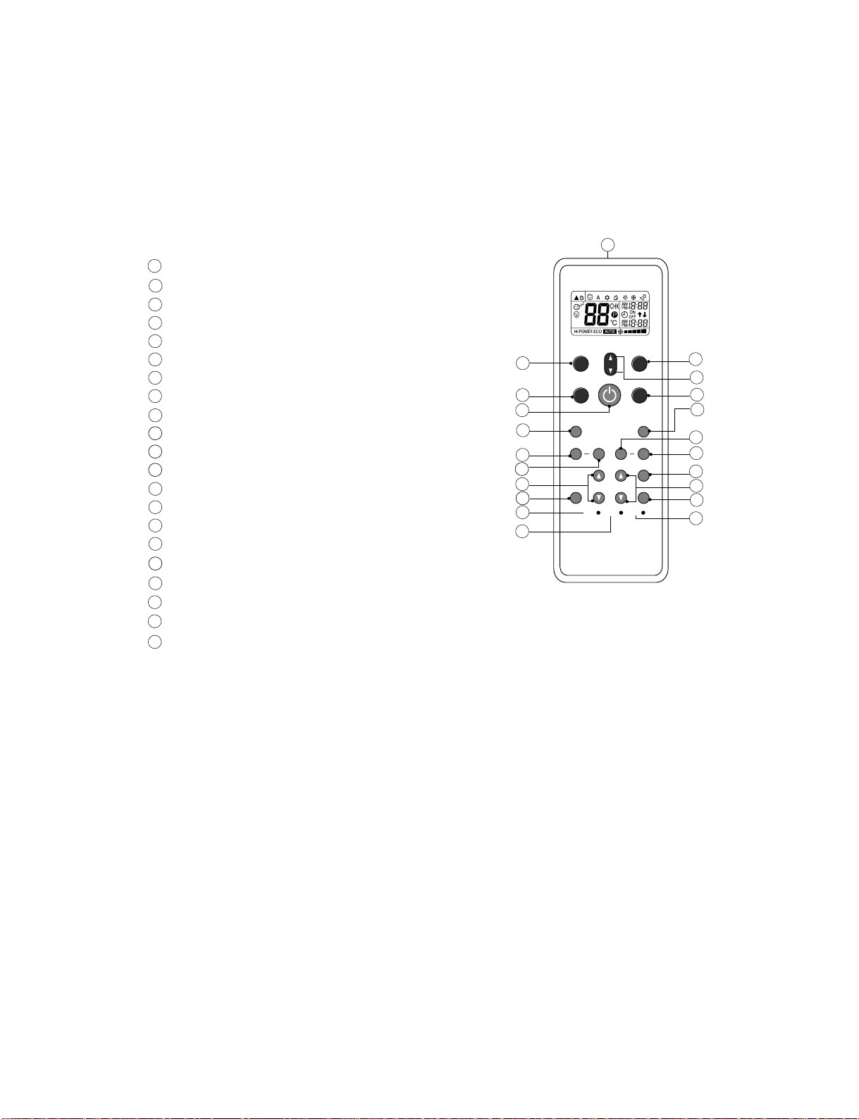
7-1. Remote control
7-1-1. Function of Push Putton
1
11
Infrared signal emitter
11
2
Start/Stop button
3
Mode select button (MODE)
4
Temperature button (TEMP)
5
Fan speed button (FAN)
6
Swing louver button (SWING)
7
Set louver button (FIX)
8
On timer button (ON)
Off timer button (OFF)
9
18
10
Sleep timer button (SLEEP)
19
Timer setup button (SET)
11
12
20
Timer clear button (CLR)
Memory and Preset button (PRESET)
13
14
One Touch button (ONE-TOUCH)
15
High power button (Hi-POWER)
16
Economy button (ECO)
17
Quiet button (QUIET)
18
Comfort sleep button (COMFORT SLEEP)
19
Filter reset button (FILTER)
20
Clock Reset button (CLOCK)
21
Check button (CHK)
FILE NO. SVM-10049
1
13
14
2
17
6
7
8
10
21
19
PRESET
ONE-TOUCH
QUIET
SWING
TIMER
SLEEP
CHK
FAN
TEMP
MODE
COMFORT
SLEEP
FIX Hi-POWER ECO
ON
OFF
FILTER
CLOCK
5
4
3
18
15
16
CLR
SET
12
9
11
20
− 16 −
Page 18
FILE NO. SVM-10049
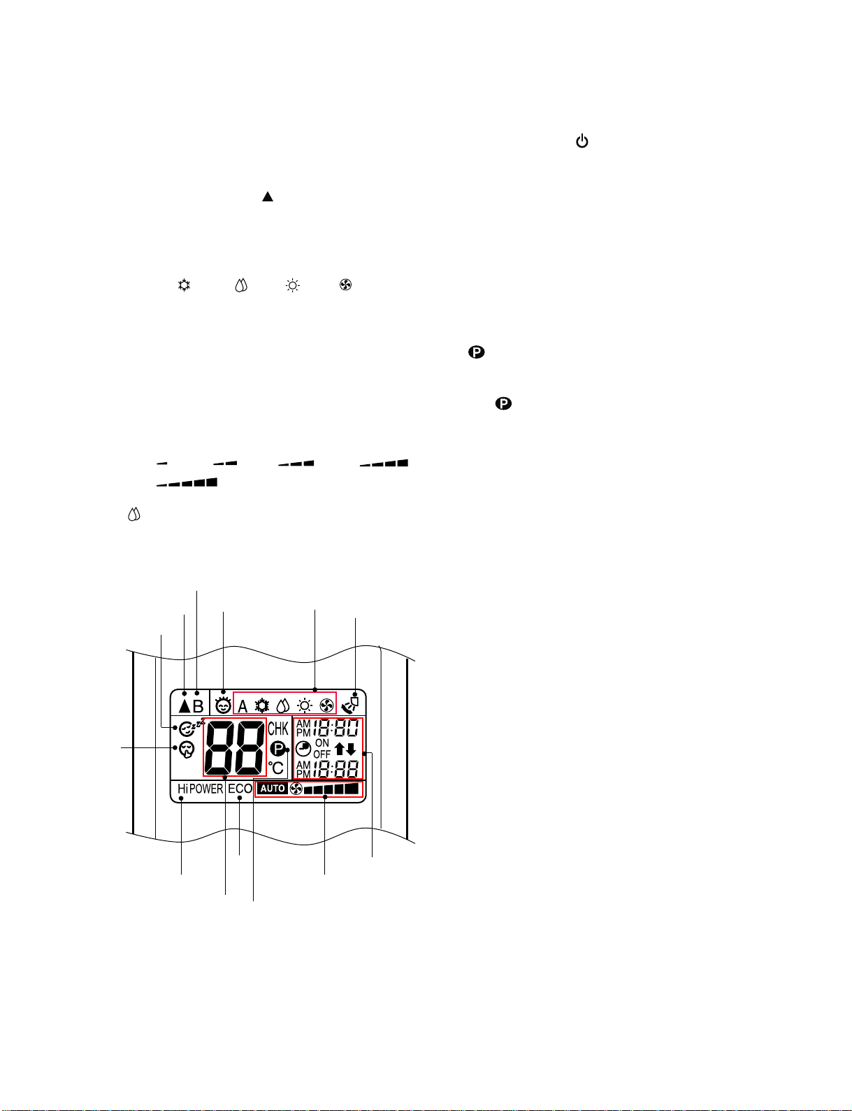
7-1-2. Display of Remote Control
All indications, except for the clock time indicator, are displayed by pressing the button.
1. Transmission mark
This transmission mark
remote controller transmits signals to the indoor
unit.
indicates when the
2. Mode indicator
Indicates the current operation mode.
(A : Auto, : Cool,
: Dry, : Heat, : Fan only)
3. Temperature indicator
Indicates the temperature setting.
(17°C to 30°C)
4. FAN speed indicator
Indicates the selected fan speed.
AUTO or five fan speed levels
LOW , LOW+ , MED , MED+ ,
(
HIGH ) can be shown.
Indicate Auto will be appear with Dry operation
( : Dry) only.
9
1
12
2
13
10
10
5. TIMER and clock time indicator
The time setting for timer operation or the clock
time is indicated.
The current time is always indicated except
during TIMER operation.
6. Hi-POWER indicator
Indicates when the Hi-POWER operation starts.
Press the Hi-POWER button to start and press it
again to stop the operation.
7. (PRESET) indicator
Flashes for 3 seconds when the PRESET button is
pressed during operation.
The
button for more than 3 seconds while the mark is
blinks.
Press another button to turn off the mark.
mark is shown when holding down the
8. ECO indicator
Indicates when the ECO is in activated.
Press the ECO button to start and press it again
to stop operation.
9. A, B change indicator remote controller
When the remote controller switching function is
set, “B” appears in the remote controller display.
(When the remote controller setting is “A”, there is
no indication at this position.)
10. Comfort sleep
Indicates when comfort sleep is activaled.
Press comfort sleep button to selectter
11
6
3
8
7
4
5
11. Quiet
Indicates when quiet is activated.
Press quiet button to start and press it again to stop
operation.
12. One-Touch
Indicates when one touch comfort is activated.
Press one-touch button to start the operation.
13. Swing
Indicates when louver is swing.
Press swing button to start the swing operation
and press it again to stop the swing operation.
− 17 −
Page 19
7-2. Outline of Air Conditioner Control
y
A
y
P
P
A
This is a fixed capacity type air conditioner, which uses
a DC motor for an indoor fan. The DC motor drive
circuit is mounted in the indoor unit. And electrical
parts which operate the compressor and the outdoor
fan motor, are mounted in the outdoor unit.
The air conditioner is mainly controlled by the indoor
unit controller. The controller operates the indoor fan
motor based upon commands transmitted by the
remote control and transfers the operation commands
to the outdoor unit.
The outdoor unit receives operation commands
from the indoor unit, and operates the outdoor
fan motor and the compressor.
(1) Role of indoor unit controller
The indoor unit controller receives the operation
commands from the remote control and executes
them.
• Temperature measurement at the air inlet of the
indoor heat exchanger by the indoor
temperature sensor
• Temperature measurement of the indoor heat
exchanger by the heat exchanger sensor
• Louver motor control
• Indoor fan motor operation control
• LED display control
• Transferring of operation commands to the
outdoor unit
• Receiving of information of the operation status
and judging of the information or indication of
error
(2) Role of outdoor unit controller
The outdoor unit controller receives the operation
commands from the indoor controller and
executes them.
• Compressor operation
control
• Operation control of
outdoor fan motor
Operations according
to the commands
from the indoor unit
FILE NO. SVM-10049
• Turning off the compressor and outdoor fan
when the outdoor unit receives the shutdown
command
• Defrost control in heating operation
(Temperature measurement by the Indoor heat
exchanger, control the four-way valve and
outdoor fan motor control)
7-2-1.
(1)
(2) Swing
7-2-2. Indoor Fan Control
Table (7-2-1) Cooling
Louver contr
V
er
tical air flow louver
ol
Position of veritcal air flow louver is automatically
controlled according to the operation mode.
Besides, position of vertical air flow louver can be
arbitrarily set by pressing [FIX] button.
The louver position which is set by [FIX] button
is stored in the microcomputer, and the louver is
automatically set at the stored position for the next
operation.
If [SWING] button is pressed when the indoor unit
is in operation, the vertical air flow louver starts
swinging. When [SWING] button is pressed, it stops
swinging.
The operation controls the fan speed at indoor unit
side. The indoor fan (cross flow fan) is operated by
the phase control induction motor. The fan rotates in 5
stages in MANUAL mode, and in 5 stages in AUTO
mode, respectively. (Table 7-2-3)
1) When setting the fan speed to L, L+,M, M+ or H
on the remote controller, the operation is performed
with the constant speed shown in Table 7-2-1 and
Table 7-2-2
Table (7-2-2) Heating
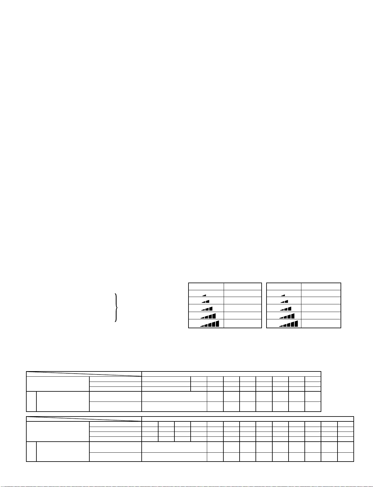
Indication
L
L+
M
M+
H
Fan speed
Low
(L + M) / 2
Med
(M + H) / 2
High
Indication
L
L+
M
M+
H
Fan speed
Low
(L + M) / 2
Med
(M + H) / 2
High
2) When setting the fan speed to AUTO on the remote
controller, revolution of the fan motor is controlled
to the fan speed level show in Table 7-2-3
according to the setup temperature, room temperature,
Table 7-2-3 Indoor fan and air flow rate
OPERATION
MODE
RAS-24SKP-ES2
Model
OPERATION
MODE
RAS-24SKHP-ES2
Model
Cooling
Fan only
Dr
rpm
ir flow volume (m3/h)
Cooling
Fan only
Dr
Heat
rpm
ir flow volume (m3/h)
UH
1340
1240
UH H M+ M L+ L L- UL SL
UH H M+ M L+ L L- UL SL
1340
1240
and heat exchanger temperature.
FAN TA
H M+ M L+ L L- UL SL
H M+ M L+ L L-
M+ M L+ L L- UL SL
1220 1100 1025 950 850 700 600
1120 1000 930 850 750 600 500
FAN TA
H M+ M L+ L L-
M+ M L+ L L- UL SL
1220 1100 1100 950 950 950 850 700 600
1120 1000 1000 850 850 850 750 600 500
- 18 -
Page 20
FILE NO. SVM-10049
7-3. Description of Operation Mode
(1) When turning on the breaker, the operation lamp
blinks. This means that the power is on (or the
power supply is cut off.)
(2) When pressing [ ] button on the
remote control, receiving beep sounds from the
indoor unit, and the next operation is performed
together with opening the vertical air flow louver.
(3) Once the operation mode is set, it is memorized in
the microcomputer so that the previous operation
can be effected thereafter simply by pressing
[ ] button.
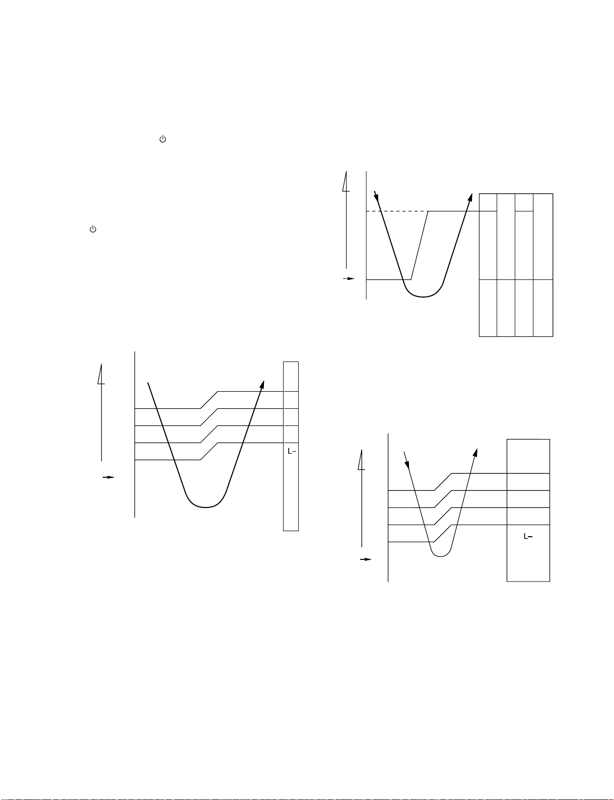
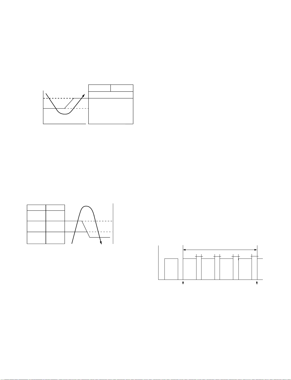
7-3-1. Fan only operation
([MODE] button on the remote control is set
to the fan only operation.)
(1) When [FAN] button is set to AUTO, the indoor fan
motor operates as shown in Fig. 7-3-1. When
[FAN] button is set to LOW, LOW+, MED, MED+ or
HIGH, the motor operates with a constant air flow.
°C
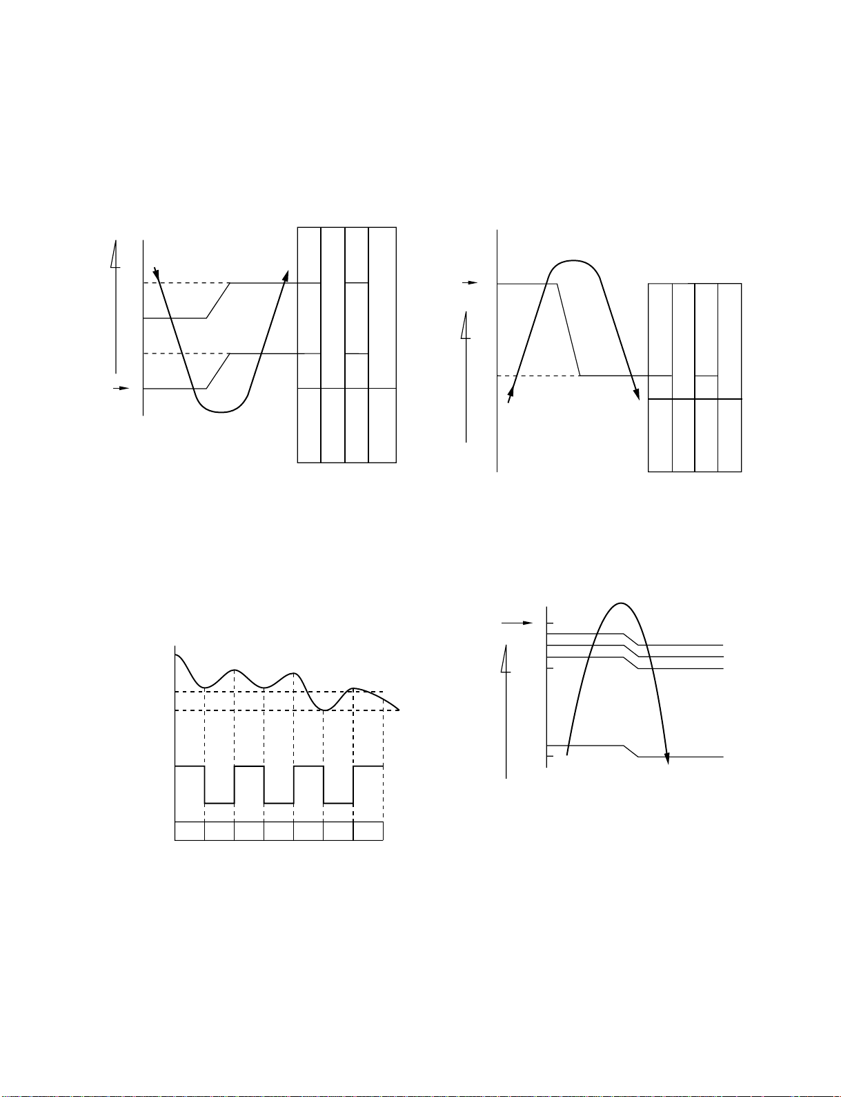
7-3-2. Cooling operation
([MODE] button on the remote control is set
to the cooling operation.)
(1) The compressor, 4-way valve, (Heat pump model
only) outdoor fan and operation display lamp are
controlled as shown in Fig. 7-3-2.
° C
ON ON
OFF OFF OFF ON
4-way valve
Compressor
Outdoor fan
OPERATION
(Room temp.) (Preset temp.)
Preset
temp.
0.5
0
Fig. 7-3-2
display lamp
+3
+2.5
+2
+1.5
+1
+0.5
(Room temp.) − (Preset temp.)
Preset
temp.
0
(Preset temp.: 24 °C)
NOTE 1 : *1 : Fan speed = (M + − L) x 3/4 + L
*2 : Fan speed = (M + − L) x 2/4 + L
*3 : Fan speed = (M + − L) x 1/4 + L
2 : The Hi Power, ECO and COMFORT SLEEP
operation can not be set
(Linear approximation from M+ and L)
Fig. 7-3-1 Setting of air flow [FAN:AUTO]
M+
*1
*2
*3
(2) When [FAN] button is set to AUTO, the indoor fan
motor operates as shown in Fig. 7-3-3. When
[FAN] button is set to LOW, LOW+, MED, MED+ or
HIGH, the motor operates with a constant air flow.
°C
(Room temp.) − (Preset temp.)
Preset
temp.
+3
+2.5
+2
+1.5
+1
+0.5
0
-0.5
M+
*1
*2
*3
NOTE1 : *1 : Fan speed = (M + − L) x 3/4 + L
*2 : Fan speed = (M + − L) x 2/4 + L
*3 : Fan speed = (M + − L) x 1/4 + L
(Linear approximation from M+ and L)
Fig. 7-3-3 Setting of air flow [FAN:AUTO]
- 19 -
Page 21
FILE NO. SVM-10049
7-3-3. Dry operation
([MODE] button on the remote control is set
to the dry operation.)
(1) The compressor, 4-way valve, (Heat pump model
only) outdoor fan and operation display lamp are
controlled as shown in Fig. 7-3-4.
° C
ON:6min.
OFF:4min.
ON
ON:5min.
OFF:5min.
OFF
4-way valve
Outdoor fan
OPERATION
display lamp
(Room temp.) (Preset temp.)
Preset
temp.
+3
+2
+1
ON:6min.
OFF:4min.
OFF
ON:5min.
OFF:5min.
OFF
0
Compressor
Fig. 7-3-4
7-3-4. Heating operation *Heat pump model only
([MODE] button on the remote control is set
to the heating operation.)
(1) The compressor, 4-way valve, outdoor fan and
operation display lamp are controlled as shown in
Fig. 7-3-6.
° C
Preset
temp.
0
0.5
(Room temp.) (Preset temp.)
ON
OFF
ON
Compressor
ON
OFF
ON
4-way valve
Outdoor fan
OPERATION
Fig. 7-3-6
display lamp
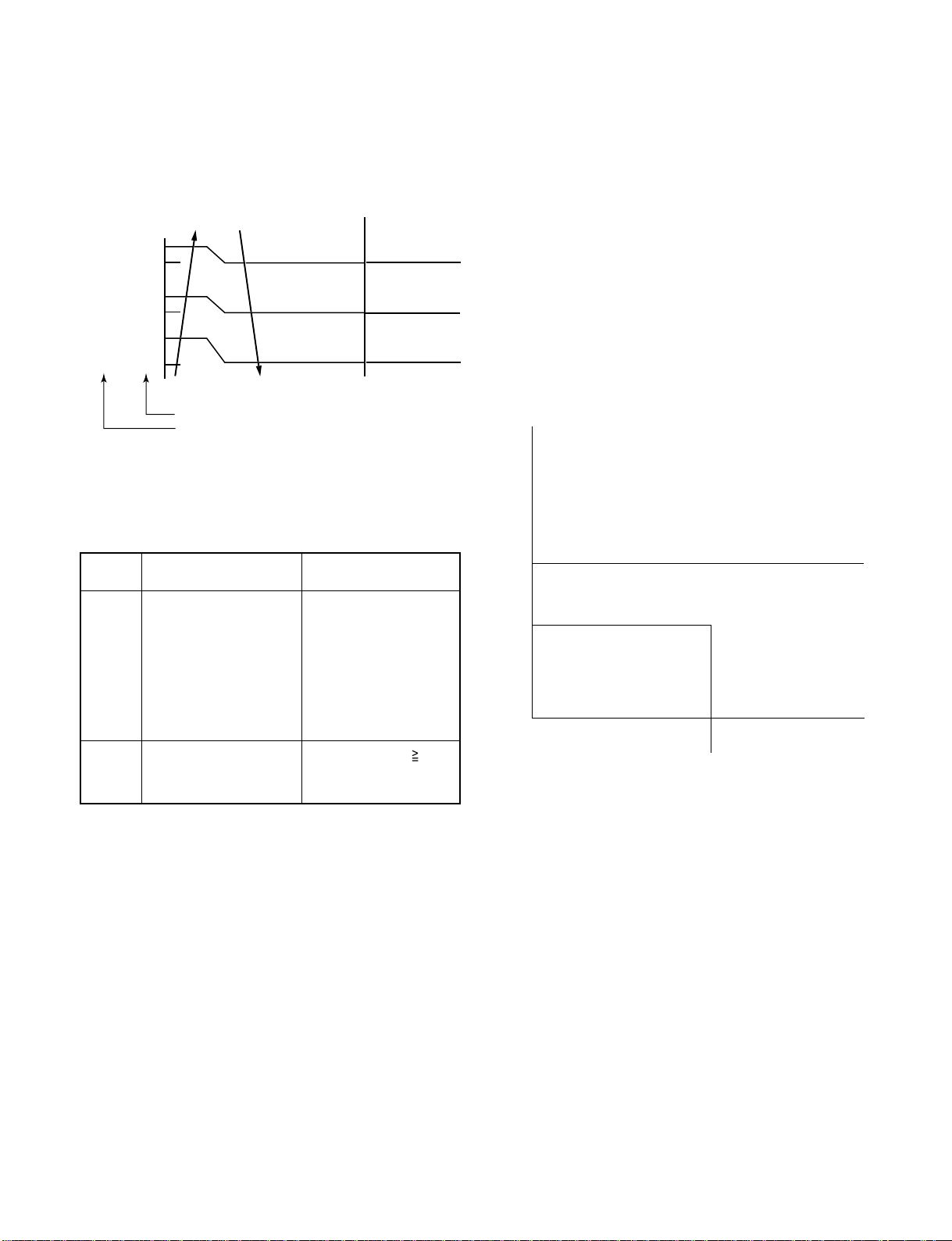
(2) The microprocessor turns the compressor on and
off at the regular intervals (4 to 6 minutes). While
the compressor is turning off, the indoor fan motor
operates in the SUPER LOW position.
The pattern of operation depending on the relation
between room temperature and preset
temperatures is shown in Fig. 7-3-5.
Room temp.
Preset temp.+1
Preset temp.
Compressor
Outdoor fan
Indoor fan
ON ON ON ON
OFF OFF OFF
L. *S.L. S.L.L. L. S.L. L.
*Super Low
Fig. 7-3-5
(3) [FAN] button on the remote control is set to AUTO
only.
(4) The ECO, COMFORT SLEEP, QUIET and
Hi POWER operations can not be set.
(2) When [FAN] button is set to AUTO, the indoor fan
motor operates as shown in Fig. 7-3-7. When
[FAN] button is set to LOW, LOW+, MED, MED+ or
HIGH, the motor operates with a constant air flow.
Preset
temp.
°C
0
-0.5
-1
-1.5
-2
-5.0
-5.5
[FAN AUTO]
(Room temp.) − (Preset temp.)
L
*1
*2
+
M
H
*1 : Fan speed = (M + − L) x 1/4 + L
*2 : Fan speed = (M + − L) x 2/4 + L
*3 : Fan speed = (M + − L) x 3/4 + L
(Calculated with Linear approximation from M+ and L+)
Fig. 7-3-7
- 20 -
Page 22
FILE NO. SVM-10049
y.
c
e
(3) The indoor heat exchanger restricts revolving
speed of the fan motor to prevent a cold draft. The
upper limit of the revolving speed is shown in
Fig. 7-3-8
Fan speed AUTO Fan speed MANUAL
46Tc34
45 33
33 21
32 20
*A+0 *A+0
*A-8 *A-8
Fan speed MANUAL or AUTO in starting
Fan speed AUTO in stability
* No limitation while fan speed MANUAL mode is in stabilit
* A: When Tsc 24, A is 24, and when Tsc < 24, A is Ts
Tsc: Set valu
Normal AUTO
Line-approximate
H and SL with Tc.
SL (W2)
Stop
L-H (Up to
setting speed)
Line-approximate
H and SL with Tc.
SL (W2)
Stop
[In starting and in stability]
In starting
FAN • Until 12 minutes
AUTO
FAN • Room temp. < Set
Manual
passed after operation
start
• When 12 to 25 minutes
passed after operation
start and room temp.
is 3°C or lower than
set temp.
temp.–4°C
In stability
• When 12 to 25 minutes
passed after opeartion
start and room temp.
is than (set )
between preset
• When 25 minutes or
more passed after
operation start
• Room temp. Set
temp. –3.5°C
3°C
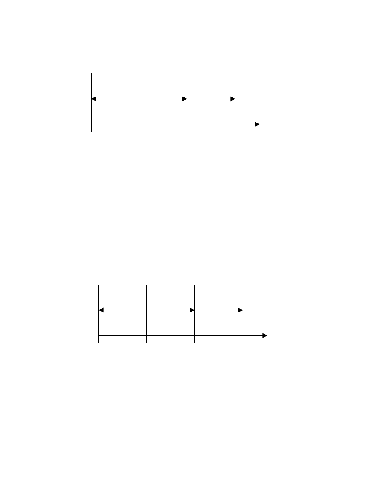
7-3-5. Automatic operation
([MODE] button on the remote control is set
to the automatic operation.)
(1) One of 3 operations (Cooling, Fan only or Heating)
is selected according to difference between the
preset temperature and the room temperature at
which the automatic operation has started, as
shown in Fig. 7-3-9. The Fan only operation
continues until the room temperature reaches a
level at which another mode is selected.
(2) Temporary Auto
When the [RESET] button on the indoor unit
is pushed, the preset temperature is fixed at 24°C
and the indoor unit is controlled as shown in
Fig. 7-3-9.
°C
Cooling operation
0
Fan only operation
-1
Heating operation
(Room temp.) − (Preset temp.)
Heat pump model Cooling model
Fig. 7-3-9
Fig. 7-3-8 Cold draft preventing control
(4) In order to prevent cold draft when compressor
during heating operation.Then louver will move
to upper position and fan speed will reduce or
OFF.
- 21 -
Page 23
7-4. Drescription of Safety and Reliability Prevention Function
FILE NO. SVM-10049
7-4-1. Low-Temperature Limit Control
The microcontroller detects the indoor heat exchanger
temperature to prevent the indoor heat exchanger from
freezing.
The compressor and outdoor fan motor are controlled
as shown in Fig. 7-4-1.
Heat exchanger
temperature
(°C)
7
4
Compressor Outdoor fan
ON
Less than 4°C continues
for 5 minutes
OFF
Fig. 7-4-1
7-4-2 High-Temperature Limit Control
*Heat pump model only
The microcontroller detects the indoor heat exchanger
temperature to prevent pressure of a refrigerating cycle
from increasing excessively.
The compressor and outdoor fan motor are controlled
as shown in Fig. 7-4-2.
7-4-3. Defrost Operation *Heat pump model only
When the indoor unit is in heating operation, if the
refrigerant evaporation temperature detected by the
outdoor heat exchanger sensor is under the specified
temperature, the outdoor unit starts the defrosting
operation. At this time, the 4-way valve relay and the
outdoor fan motor are turned off. The indoor fan motor
is also turned off by the cold draft preventing control of
the indoor microcomputer. Then, [PRE. DEF.] lamp on
the indoor unit comes on.
The defrosting operation stops and the 4-way valve
relay, outdoor fan motor and the indoor fan motor are
turned on automatically when the refrigerant
evaporation increases to the specified temperature, or
when the defrosting time is over 12 minutes.
7-4-3-1. Defrost starting condition
A-Zone : If -10°C > Teo ≥
start when.
Teo - Te ≥
~ 30 min after operation.
B-Zone : If Te ≤
-18°C, defrost start instantaneously
(Suddenly) 00 ~ 25 min ofter operation
C-Zone : If -2ºC ≥
Teo ≥ -10°C defrost will start when
Teo - Te ≤ -3°C at least 20 sec or ~ 60 min
after operation.
- 18°C, defrost will
2.5°C at teat 20 sec or
Compressor
OFF
ON
ON
Outdoor fan
OFF
OFF
ON
Fig. 7-4-2
Heat exchanger
temp.
(°C)
62
55
54
7-4-3-2. Defrost finish condition.
1) If Te ≥ 3°C at least 60 sec -->4 way value on.
2) If Te ≥ 8°C --> 4 way value on.
Timing
Operation time (4 Loops = Tt)
Td1
Td2
Td3 Td4
Finish time recordStart time record
Defrost time rate : (Td/Tt) x 100
Heating time rate : (Tt - Td) x Tt
Fig. 7-4-3
- 22 -
Page 24
FILE NO. SVM-10049
7-5. One-Touch Operation
(Heatpump Model : RAS-24SKHP-ES2)
One touch comfort is the fully automated operation that is set according to the preferable condition in a region.
Fan
Operation
AUTO
*AUTO/L
L
0
*AUTO/L : Fan operates depends on the setting temperature and room temperature.
During the One Touch Comfort mode if the indoor unit receives any signal with other operation mode, the unit
will cancel the comfort mode and operates according to the signal received.
Operation description
When an indoor unit receives "One Touch Comfort Signal" from the remote controller, the indoor unit operates
as following.
1) Air conditioner starts to operation when the signal is received, even if the air conditioner was OFF.
2) Operation mode is set according to room temperature, the same as AUTO mode.
3) Target temperature is 24ºC.
4) Louver position is set as stored position.
(Cooling Only Model : RAS-24SKP-ES2)
One touch comfort is the fully automated operation that is set according to the preferable condition in a region.
Fan
Operation
Hi-POWER
12
Fig. 7-5-1
25
*AUTO/L
Time after operation
starts (min)
0
*AUTO/L : Fan operates depends on the setting temperature and room temperature.
During the One Touch Comfort mode if the indoor unit receives any signal with other operation mode, the unit
will cancel the comfort mode and operates according to the signal received.
Operation description.
When an indoor unit receives "One Touch Comfort Signal" from the remote controller, the indoor unit operates
as following.
1) Air conditioner starts to operation when the signal is received, even if the air conditioner was OFF.
2) Operation mode is set Cooling mode.
3) Target temperature is 22ºC.
4) Louver position is set swing.
5) Fan is controlled as diagram.
12
Fig. 7-5-2
25
- 23 -
Time after operation
starts (min)
Page 25

FILE NO. SVM-10049
7-6. Hi POWER Operation
([Hi POWER] button on the remote
control is pressed.)
When [Hi POWER] button is pressed while the indoor
unit is in Auto, Cooling or Heating operation, Hi
POWER mark is indicated on the display of the remote
control and the unit operates as follows.
(1) Automatic operation
The indoor unit operates in according to the
·
current operation.
(2) Cooling operation
• The setting temperature drops 3°C.
(The value of the setting temperature on the
remote control does not change.)
• If the room temperature is higher than the
setting temperature by 3.5°C or more, the
horizontal louver moves to the Hi POWER
position automatically. Then when the room
temperature is 1°C less than the setting
temperature the horizontal louver returns
automatically.
• FAN speed : [AUTO]
If the room temperature is higher than the
setting temperature by 3.5°C or more, the air
conditioner operates at maximum airflow level.
If the room temperature is higher than the
setting temperature by less than 3.5°C, the air
conditioner operates at normal airflow level.
• FAN speed : One of 5 levels
If the room temperature is higher than the
setting temperature by 3.5°C or more, the air
conditioner operates at higher consecutive
airflow level. If the room temperature is higher
than the setting temperature by less than 3.5°C,
the air conditioner operates at normal airflow
level.
The indoor unit's fan speed level increase 1 tap
·
(3) Heating operation *Heat pump model only
The preset temperature increases 2°C,
·
(The value of the preset temperature on the
remote control does not change.)
The indoor unit operates in normal heating
·
mode except the preset temperature is higher
(+2°C).
The indoor unit's fan speed level increase 1 tap
·
(4) The Hi POWER mode can not be set in Dry or
Fan only operation.
(5) The Hi POWER mode can memorize with timer
function.
7-7. QUIET Operation
When the [QUIET] button is pressed, the fan of the
indoor unit will be restricted the revolving speed at
speed L− until the [QUIET] button is pressed once
again (cancel Quiet mode).
Quiet mode is the system which, control the revolving
speed of indoor fan to work constantly at lower than
speed L. In addition, noise level of indoor unit is less
than usual.
Remarks :
1. Quiet mode is unable to work in dry mode.
2. Quiet mode is appropriate to work with less cooling
load and less heating load condition. Because of the
fan speed L− may cause not enough the cooling
capacity or heating capacity.
7-8. ECO Operation.
Cooling operation
·
The preset temperature will increase 1ºC after the
ECO mode has operated for 1 hour and the temperature
will increase another 1ºC after the ECO mode has
operated for 2 hour. (the value of the preset temperature
on the remote control does not change.)
·
The indoor fan speed is depend on presetting and can
change every speed after setting ECO operation.
Heating operation *Heat pump model only
·
The preset temperature will drop down 1ºC after the
ECO mode has operated for 1 hour and the temperature
will drop down another 1ºC after the ECO mode has
operated for 2 hour. (the value of the preset temperature
on the remote control does not change.)
·
The indoor fan speed is depend on presetting and can
change every speed after setting ECO operation.
7-9. COMFORT SLEEP Operation
Cooling operation
·
The preset temperature will increase 1ºC after the comfort
sleep mode has operated for 1 hour and the temperature
will increase another 1ºC after the comfort sleep mode
has operated for 2 hour. (the value of the preset temperrature on the remote control does not change)
·
Press the [COMFORT SLEEP] button to select this
function. The comfort sleep function will be activate
togetther with Auto shut down function. Period of
operation time can be select by re-press the
[COMFORT SLEEP] button. The period of operation
time are follows.
1H 3H 5H 9H
– 24 –
Cancel
Page 26

FILE NO. SVM-10049
Heating mode *Heat pump model only
·
The preset temperature will drop down 1ºC after the
comfort sleep mode has operated for 1 hour and
the temperature will decrease another 1ºC after
the comfort sleep mode has operated for 2 hour.
(The value of the preset temperature on the remote
control does not change.)
·
Press the [COMFORT SLEEP] button to select this
function and period of operation time same as
cooling mode operation.
The principles of comfort sleep mode are:
·
Quietness for more comfortable. When room
temperature reach setting temperature.
·
Save energy by changing room temperature
automatically.
·
The air condition can shut down by itself automatically.
Remarks :
Comfort sleep mode will not operate in dry mode
and fan only mode.
7-10. FILTER Check lamp
When the elapsed time reaches 1000 hours after air
purifier operation, the FILTER indicator lights. After
cleaning the filters, turn off the FILTER indicator.
How to Turn Off FILTER Indicator
Press [RESET] button on the indoor unit or press filter
button on the remote control.
NOTE :
If [RESET] button is pushed while the FILTER indicator
is not lit, the indoor unit will start the automatic operation.
When you want a temporary operation while the FILTER
lamp lights, press [RESET] button to turn off the FILTER
lamp.
– 25 –
Page 27

FILE NO. SVM-10049
7-11. Auto Restart Function
This indoor unit is equipped with an automatic restarting function which allows the unit to restart operating with
the set operating conditions in the event of a power supply being accidentally shut down.
The operation will resume without warning three minutes after power is restored.
This function is not set to work when shipped from the factory. Therefore it is necessary to set it to work.
7-11-1. How to Set the Auto Restart Function
To set the auto restart function, proceed as follows:
The power supply to the unit must be on ; the function will not set if the power is off.
Press the [RESET] button located in the center of the front panel continuously for three seconds.
The unit receives the signal and beeps three times.
The unit then restarts operating automatically in the event of power supply being accidentally shut down.
• When the unit is standby (Not operating)
Operation
Press [RESET] button for more than
three seconds. (Less than 10 seconds)
Hi POWER FILTER PAP TIMER OPERATION
RESET
RESET button
• When the unit is in operation
Operation
Press [RESET] button for more than
three seconds. (Less than 10 seconds)
Motions
The unit is on standby.
↓
The unit starts to operate. The green indicator is on.
↓ After approx. three seconds,
The unit beeps three times The green indicator blinks
and continues to operate. for 5 seconds.
If the unit is not required to operate at this time, press [RESET]
button once more or use the remote controller to turn it off.
Motions
The unit is in operation. The green indicator is on.
↓
The unit stops operating. The green indicator is turned off.
Hi POWER FILTER PAP TIMER OPERATION
RESET
RESET button
↓ After approx. three seconds,
The unit beeps three times. The green indicator blinks
for 5 seconds.
If the unit is required to operate at this time, press [RESET] button
once more or use the remote controller to turn it on.
– 26 –
Page 28

FILE NO. SVM-10049
7-11-2. How to Cancel the Auto Restart Function
To cancel auto restart function, proceed as follows :
Repeat the setting procedure : the unit receives the signal and beeps three times.
The unit will be required to be turned on with the remote controller after the main power supply is turned off.
• When the system is on stand-by (not operating)
Operation
Press [RESET] button for more than
three seconds. (Less than 10 seconds)
Hi POWER FILTER PAP TIMER OPERATION
RESET
RESET button
• When the system is operating
Operation
Press [RESET] button for more than
three seconds. (Less than 10 seconds)
Motions
The unit is on standby.
↓
The unit starts to operate. The green indicator is on.
↓ After approx. three seconds,
The unit beeps three times and continues to operate.
If the unit is not required to operate at this time, press [RESET]
button once more or use the remote controller to turn it off.
Motions
The unit is in operation. The green indicator is on.
↓
The unit stops operating. The green indicator is turned off.
↓ After approx. three seconds,
The unit beeps three times.
Hi POWER FILTER PAP TIMER OPERATION
If the unit is required to operate at this time, press [RESET] button
once more or use the remote controller to turn it on.
RESET button
RESET
7-11-3. Power Failure During Timer Operation
When the unit is turned off because of power failure
during timer operation, the timer operation is cancelled.
In that case, set the timer operation again.
NOTE :
The Everyday Timer is reset while a command signal
can be received from the remote controller even if it
stopped due to a power failure.
– 27 –
Page 29

FILE NO. SVM-10049
7-12. Self-Cleaning Operation
Unit now performing cooling or dry operation
Press “STOP” button
Only timer indicator lights, and Self-Cleaning operation starts
Time set now elapses
Operation stops
• During Self-Cleaning operations: The louver opens
slightly. The indoor fan operates continuously at
a speed of SL rpm.
1. Purpose
The Self-Cleaning operation is to minimize the growth of mold,
bacteria etc. by running the fan and drying so as to keep
the inside of the air conditioner clean.
Self-Cleaning operation
When the cooling or dry operation shuts down, the unit
automatically starts the Self-Cleaning operation which is
then performed for the specified period based on duration
of the operation which was performed prior to the shutdown,
after which the Self-Cleaning operation stops.
(The Self-Cleaning operation is not performed after a
heating operation.)
2. Operation
1) When the stop signal from the remote controller or
timer-off function is received, only the timer indicator
light.
2) The period of the Self-Cleaning operation is determined
by the duration of the operation performed prior to
the reception of the stop code.
3) After the Self-Cleaning operation has been performed
for the specified period, the unit stops operation.
Self-Cleaning operation times
Operation time
Up to 10 minutes
Cooling: Auto (cooling) Dry
Heating: Auto (heating)
Auto (fan only)
Shutdown
• To stop an ongoing Self-Cleaning operation at any time
Press the start/stop button on the remote controller twice during the Self-Cleaning
operation. [After pressing the button for the first time, press it for the
second time without delay (within 10 minutes)].
10 minutes
or longer
No Self-Cleaning operation performed
Self-Cleaning operation time
No Self-Cleaning operation
performed (0 minutes)
20 mins.
– 28 –
Page 30

FILE NO. SVM-10049
7-12-1. Self-Cleaning diagram
Operation display ON OFF OFF
FCU fan
FCU louver OPEN OPEN (12.7º) CLOSE
Timer display
Compressor
CDU fan ON or OFF
rpm is depend on presetting. (SL)
depend on presetting of timer function. depend on presetting of timer function.
depend on presetting per room temperature.
depend on presetting per room temperature.
Cool mode or dry mode
operation more than 10 mins.
7-12-2. Self-Cleaning function release
How to cencel Self-Cleaning function
To cancel the Self-Cleaning function, proceed as
follows:
• Press [RESET] button one time or use remote
control to turn on air conditioner. Display will show
in green color.
• Hold down the [RESET] button for more than
20 seconds. (The air conditioner will stop suddenly
when the [RESET] is pressed but keep holding it
continue. The will beep 3 times in the first
3 seconds but it is not related to Self-Cleaning
function)
• After holding about 20 seconds, the air conditioner
will beep 5 times without any blinking of display.
• The Self-Cleaning Operation had been cancelled.
Remark
Presetting of Self-Cleaning function above, AUTO-
ON ON
ON or OFF
ON or OFF
Turn off by remote controller or
timer-off function.
ON
OFF OFF
OFF OFF
Self-Cleaning mode
operate 20 mins.
Automatically turn-off.
How to set Self-Cleaning function
To set the Self-Cleaning function, proceed as follows.
• Press [RESET] button one time or use remote
control to turn on air conditioner. Display will show
in green color.
• Hold down the [RESET] button for more than
20 seconds. (The air conditioner will stop suddenly
when the [RESET] is pressed but keep holding it
continue. Then will beep 3 times is the first 3
seconds but it is not related to Self-Cleaning
function)
• After holding about 20 seconds, the air conditioner
will beep 5 times and OPERATION display blinks
5 times.
• The Self-Cleaning function had been set.
Remark
Presetting of Self-Cleaning function above, AUTORESTART function had been cancelled. To set
AUTO-RESTART again.
RESTART function had been cancelled. To set
AUTO-RESTART again.
OFF
ON or OFF
Operation time
– 29 –
Hi POWER FILTER PAP TIMER OPERATION
RESET
RESET button
Page 31

FILE NO. SVM-10049
8. INSTALLATION PROCEDURE
8-1.Safety Cautions
For general public use
Power supply cord of parts of appliance for outdoor use shall be at least polychloroprene sheathed flexible cord (design H07RN-F) or cord designation
60245 IEC66, 4.0 mm2 or more and 1.5 mm2 or more for connecting cable. (Shall be installed in accordance with national regulations.)
CAUTION
This appliance must be connected to the main power supply by means of a circuit breaker or a switch with a
contact separation of at least 3 mm in all poles.
If this is not possible, a power supply plug with earth must be used. This plug must be easily accessible after
installation. The plug must be disconnected from the power supply socket in order to disconnect the
appliance completely from the mains.
To Disconnect the Appliance from the Main Power Supply.
DANGER
• FOR USE BY QUALIFIED PERSONS ONLY.
• TURN OFF MAIN POWER SUPPLY BEFORE ATTEMPTING ANY ELECTRICAL WORK. MAKE SURE
ALL POWER SWITCHES ARE OFF. FAILURE TO DO SO MAY CAUSE ELECTRIC SHOCK.
• CONNECT THE CONNECTING CABLE CORRECTLY. IF THE CONNECTING CABLE IS CONNECTED
WRONGLY, ELECTRIC PARTS MAY BE DAMAGED.
• CHECK THE EARTH WIRE THAT IT IS NOT BROKEN OR DISCONNECTED BEFORE INSTALLATION.
• DO NOT INSTALL NEAR CONCENTRATIONS OF COMBUSTIBLE GAS OR GAS VAPORS.
FAILURE TO FOLLOW THIS INSTRUCTION CAN RESULT IN FIRE OR EXPLOSION.
• TO PREVENT OVERHEATING THE INDOOR UNIT AND CAUSING A FIRE HAZARD, PLACE THE UNIT
WELL AWAY (MORE THAN 2 M) FROM HEAT SOURCES SUCH AS RADIATORS, HEATORS,
FURNACE, STOVES, ETC.
• WHEN MOVING THE AIR-CONDITIONER FOR INSTALLING IT IN ANOTHER PLACE AGAIN, BE VERY
CAREFUL NOT TO GET THE SPECIFIED REFRIGERANT (R410A) WITH ANY OTHER GASEOUS
BODY INTO THE REFRIGERATION CYCLE. IF AIR OR ANY OTHER GAS IS MIXED IN THE
REFRIGERANT, THE GAS PRESSURE IN THE REFRIGERATION CYCLE BECOMES ABNORMALLY
HIGH AND IT RESULTINGLY CAUSES BURST OF THE PIPE AND INJURIES ON PERSONS.
• IN THE EVENT THAT THE REFRIGERANT GAS LEAKS OUT OF THE PIPE DURING THE
INSTALLATION WORK, IMMEDIATELY LET FRESH AIR INTO THE ROOM. IF THE REFRIGERANT GAS
IS HEATED BY FIRE OR SOMETHING ELSE, IT CAUSES GENERATION OF POISONOUS GAS.
WARNING
• Never modify this unit by removing any of the safety guards or bypassing any of the safety interlock
switches.
• Do not install in a place which cannot bear the weight of the unit.
Personal injury and property damage can result if the unit falls.
• Before doing the electrical work, attach an approved plug to the power supply cord.
Also, make sure the equipment is properly earthed.
• Appliance shall be installed in accordance with national wiring regulations.
If you detect any damage, do not install the unit. Contact your TOSHIBA dealer immediately.
CAUTION
• Exposure of unit to water or other moisture before installation could result in electric shock.
Do not store it in a wet basement or expose to rain or water.
• After unpacking the unit, examine it carefully for possible damage.
• Do not install in a place that can increase the vibration of the unit. Do not install in a place that can amplify
the noise level of the unit or where noise and discharged air might disturb neighbors.
• To avoid personal injury, be careful when handling parts with sharp edges.
• Please read this installation manual carefully before installing the unit. It contains further important instruc-
tions for proper installation.
– 30 –
Page 32

FILE NO. SVM-10049
REQUIREMENT OF REPORT TO THE LOCAL POWER SUPPLIER
Please make absolutely sure that the installation of this appliance is reported to the local power supplier
before installation. If you experience any problems, or if the installation is not accepted by the supplier, the
service agency will take adequate countermeasures.
– 31 –
Page 33

8-2. Installation Diagram of Indoor and Outdoor Units
e
r
o
m
r
o
m
m
0
5
Hook
Remote control holder
4
Hook
Installation
1
plate
1
7
0
5
TOSHIBA New IAQ filter
3
Batteries
1
7
0
(
A
t
t
a
c
h
t
o
t
h
e
f
r
o
n
6
TOSHIBA New IAQ filter
m
m
o
r
t
p
a
n
e
l
8 Pan head
m
o
r
e
A
i
r
.
)
wood screw
f
i
l
t
e
r
m
m
o
r
Shield pipe
FILE NO. SVM-10049
For the rear left and left piping
Wall
m
o
r
e
Insert the cushion between the
indoor unit and wall, and tilt the
indoor unit for better operation.
Do not allow the drain hose to get
slack.
Cut the piping
hole sloped
slightly.
Make sure to run the drain hose
sloped downward.
The auxiliary piping can be
connected to the left, rear left, rear
right, right, bottom right or bottom
left.
2 Wireless remote control
1
5
0
m
m
Before installing the wireless remote controller
• Loading Batteries
1. Remove the battery cover.
2. Insert 2 new batteries (AAA type)
following the (+) and (
o
r
m
o
r
e
o
m
m
0
0
0
1
-
) positions.
Vinyl tape
Apply after carrying
out a drainage test.
e
r
o
m
r
o
2
m
m
0
0
5
e
r
o
m
r
0
0
Saddle
m
m
Right
Rear right
Bottom right
Rear
left
Left
Bottom left
Insulate the refrigerant pipes
separately with insulation, not
e
r
o
m
r
o
Extension
drain hose
(Not available,
provided by installer)
together.
8 mm thick heat resisting
polyethylene foam
6
0
0
m
m
o
r
m
o
r
e
A
C
L
3 Batteries
2 Wireless remote controller
– 32 –
Page 34

8-3.Installation
8-3-1. Optional installation parts
FILE NO. SVM-10049
Part
Code
Refrigerant piping
Liquid side : ∅6.35 mm
A
Gas side : ∅12.70 mm
Pipe insulating material
B
(polyethylene foam, 8 mm thick)
Putty, PVC tapes
C
<Fixing bolt arrangement of outdoor unit>
525 mm
400 mm
365 mm
150 mm
600 mm 150 mm
Air inlet
45 mm
Parts name
Q'ty
One
each
1
One
each
Air outlet
Drain nipple mounting hole
Fig. 8-3-1
·
Secure the outdoor unit with fixing bolts and nuts if the unit is likely to be exposed to a strong wind.
Use ∅ 8 mm or ∅ 10 mm anchor bolts and nuts.
·
– 33 –
Page 35

8-3-2. Accessory and installation parts
FILE NO. SVM-10049
Part
No.
Part name (Q’ty)
1
Installation plate x 1
2
Wireless remote control x 1
3
Battery x 2
Others
Owner’s manual
Installation manual
Name
Part
No.
Part name (Q’ty)
4
Remote control holder x 1
5
TOSHIBA New IAQ filter x 2
6
TOSHIBA New IAQ filter x 2
7
Mounting screw ∅4 x 25 x 6
Part
No.
Part name (Q ’ty)
8
Pan head wood screw
∅3
.1 x 16
l
x 2
9
Screw ∅ 4 x 10 x 2
l
!
Cap water proof x 2
11
l
Drain nipple* x 1
The part marked with asterisk (
outdoor unit.
*) is packaged with the
– 34 –
Page 36

FILE NO. SVM-10049
3-3-3. Installation/Servicing Tools
<Changes in the product and components>
In the case of an air conditioner using R410A, in order to prevent any other refrigerant from being charged
accidentally, the service port diameter of the outdoor unit control valve (3 way valve) has been changed.
(1/2 UNF 20 threads per inch)
• In order to increase the pressure resisting strength of the refrigerant piping, flare processing diameter and
size of opposite side of flare nuts has been changed. (for copper pipes with nominal dimensions 1/2 and 5/8)
New tools for R410A
New tools for R410A
Gauge manifold
Charge hose
Electronic balance
for refrigerant charging
Torque wrench
(nominal diam. 1/2, 5/8)
Flare tool
(clutch type)
Gauge for projection
adjustment
V acuum pump adapter
Applicable to R22 model Changes
As pressure is high, it is impossible to measure by
means of conventional gauge. In order to prevent any
other refrigerant from being charged, each port
diameter has been changed.
In order to increase pressure resisting strength, hose
materials and port size have been changed (to 1/2
UNF 20 threads per inch).
When purchasing a charge hose, be sure to confirm
the port size.
As pressure is hight and gasification speed is fast, it
is difficult to read the indicated value by means of
charging cylinder, as air bubbles occur.
The size of opposite sides of flare nuts have been
increased. Incidentally, a common wrench is used for
nominal diameters 1/4 and 3/8.
By increasing the clamp bar’s receiving hole, strength
of spring in the tool has been improved.
—
Used when flare is made by using conventional flare
tool.
Connected to conventional vacuum pump. It is
necessary to use an adapter to prevent vacuum
pump oil from flowing back to the charge hose.
The charge hose connecting part has two ports-one
for conventional refrigerant (7/16 UNF 20 threads per
inch) and one for R410A. If the vacuum pump oil
(mineral) mixes with R410A a sludge may occur and
damage the equipment.
Gas leakage detector
• Incidentally, the “refrigerant cylinder” comes with the refrigerant designation (R410A) and protector coating in
the U. S’s ARI specified rose color (ARI color code: PMS 507).
• Also, the “charge port and packing for refrigerant cylinder” require 1/2 UNF 20 threads per inch
corresponding to the charge hose’s port size.
Exclusive for HFC refrigerant.
– 35 –
Page 37

FILE NO. SVM-10049
8-4. Indoor Unit
8-4-1. Installation Place
• A place which provides enough spaces around the
indoor unit as shown in the diagram.
• A place where there are no obstacle near the air
inlet and outlet.
• A place which allows easy installation of the piping
to the outdoor unit.
• A place which allows the front panel to be opened.
• The indoor unit shall be installed so that the top of
the indoor unit is positioned at least 2m in height.
• Also, avoid putting anything on the top of the
indoor unit.
CAUTION
• Direct sunlight on the indoor unit wireless
receiver should be avoided.
• The microprocessor in the indoor unit should
not be too close to r-f sources.
(For details, see the owner's manual.)
<Remote control>
• Should be placed where there are no obstacles,
such as curtains, that may block the signal.
• Do not install the remote controller in a place
exposed to direct sunlight or close to a heating
source, such as a stove.
• Keep the remote controller at least 1 m away from
the nearest TV set or stereo equipment.
(This is necessary to prevent image disturbances or
noise interference.)
• The location of the remote controller should be
determined as shown below.
(Side view)
Indoor unit
(Top view)
Indoor unit
8-4-2. Drilling a Hole and Mounting Instal-
lation Plate
<Drilling a hole>
When install the refrigerant pipes from the rear.
e center of pipe hole
m from the right side edge is
23mm
35 120 180 240
Pipe hole
dia.65mm
The center of the pipe hole is above
the arrow.
Fig. 8-4-2
1. After determining the pipe hole position on the
installation plate ( ð ) drill the pipe hole (Ø65
mm) at a slight downward slant to the outdoor
side.
NOTE :
• When drilling into a wall that contains a metal lath,
wire lath or metal plate, be sure to use a pipe hole
brim ring sold separately.
<Mounting the installation plate>
Anchor bolt holes
5
3
2
1
0
8
1
0
4
2
50
o
T
0
Hook
e
n
i
l
t
u
o
t
i
n
u
o
T
0
7
1
m
m
0
4
2
the center of pipe hole
5
8
Offset 85mm from the left side edge is
e
n
i
l
t
u
o
t
ni
u
o
T
m
5m
3
e
n
i
l
t
u
o
t
ni
u
o
T
m
m
20
1
3
2
0
40
Offset 23mm from the right side edge is
0
7
1
e
n
i
l
t
u
o
t
i
n
u
m
m
0
4
2
the center of pipe hole
2
3
1
3
2
m
m
5
6
.
a
i
d
2 m or more from floor
Reception
range
Remote
controller
Fig. 8-4-1
Reception
range
Remote controller
– 36 –
Pipe hole
Indoor unit
Hook
Thread
7
Weight
Fig. 8-4-3
Hook
Mounting
Screw
Pipe hole (dia. 65mm)
Installation
1
plate
Page 38

FILE NO. SVM-10049
<When the installation plate is directly
mounted on the wall>
1. Securely fit the installation plate onto the wall by
screws with the upper and lower catches, that
hold the indoor unit, facing out.
2. To mount the installation plate on a concrete wall
use anchor bolts. Drill the anchor bolt holes as
illustrated in the above figure.
3. Install the installation plate horizontally and level.
CAUTION
When installing the installation plate with mounting screw, do not use the anchor bolt hole.
Otherwise the unit may fall down and result in
personal injury and property damage.
Installation plate
<Keep horizontal direction>
Anchor bolt
Projection
15mm or less
8-4-3. Electrical Work
1. The supply voltage must be the same as the
rated voltage of the air conditioner.
2. Prepare a power source for the exclusive use of
the air conditioner.
NOTE :
• Wire type :
More than 1.5 mm2 H07RN-F or 60245IEC66.
CAUTION
• This appliance can be connected to a main
circuit breaker in either of the following two
ways.
1. Connection to fixed wiring:
A switch or circuit breaker which disconnects all poles and has a contact separation of at least 3 mm must be incorporated
in the fixed wiring. An approved circuit
breaker or switch must be used.
2. Connection with power supply plug:
Attach power supply plug with power cord
and plug it into wall outlet. An approved
power supply cord and plug must be used.
Fig. 8-4-4
5 mm dia. hole
7 Mounting screw
Ø4 × 25
Clip anchor
(local parts)
l
Fig. 8-4-5
CAUTION
Failure to securely install the unit may result in
personal injury and/or property damage if the
unit falls.
• In case of block, brick, concrete or similar type
walls, drill 5 mm dia. holes in the wall.
• Insert clip anchors for the mounting screws.
NOTE :
• Install the installation plate using mounting screws
between 4 to 6, being sure to secure all four
corners.
NOTE :
• Perform wiring work being sure the wire length is
long enough.
8-4-4. Wiring Connection
<How to connect the connecting cable>
Wiring the connecting cable can be carried
out without removing the front panel.
1. Remove the air inlet grille. Open the air inlet grille
upward and pull it toward you.
2. Remove the terminal cover and cord clamp.
3. Insert the connecting cable (or as according to
local regulations/codes) into the pipe hole on the
wall.
4. Pull the connecting cable through the cable slot
on the rear panel so that it protrudes about
15 cm out of the front.
5. Insert the connecting cable fully into the terminal
block and secure it tightly with screws.
6. Tightening torque: 1.2 N•m (0.12 kgf•m)
7. Secure the connecting cable with the cord clamp.
8. Attach the terminal cover, rear plate bushing and
air inlet grille on the indoor unit.
– 37 –
Page 39

FILE NO. SVM-10049
CAUTION
CAUTION
• Be sure to refer to the wiring system diagram
labeled inside the front panel.
• Check local electrical regulations for any
specific wiring instructions or limitations.
Cord clamp
Terminal cover
Screw
Connecting cable
Screw
ab
out
1
20 mm
5 c
m
Fig. 8-4-6
110 mm
Terminal block
1
2
3
Earth line
Connecting cable
Ear
th line
8-4-5. Piping and Drain Hose Installation
<Piping and drain hose forming>
• Since condensation results in machine trouble,
make sure to insulate both the connecting pipes
separately.
(Use polyethylene foam as insulating material.)
Rear right
Rear left
Bottom left
Changing
Left
drain hose
Bottom right
Die-cutting
Right
Front panel slit
Fig. 8-4-8
1. Die-cutting front panel slit
Cut out the slit on the left or right side of the front
panel for the left or right connection and the slit
on the bottom left or side of thefront panel for the
bottom left or right connection with a pair of
nippers.
2. Changing drain hose
For left connection, left-bottom connection and
rear-left connection’s piping, it is necessary to
relocate the drain hose and drain cap.
Piping preparation
10 mm
80 mm
Stripping length of the connecting cable
Fig. 8-4-7
NOTE :
• Use stranded wire only.
• Wire type : H07RN-F or more
<How to remove the drain cap>
Clip drain cap with needle-nose pliers, and pull out.
Fig. 8-4-9
<How to remove the drain hose>
The drain hose is secured in place by a screw.
Remove the screw securing the drain hose, then pull
out the drain hose.
Heat insulator
Drain hose
– 38 –
Fig. 8-4-10
Page 40

FILE NO. SVM-10049
<How to attach the drain cap>
1. Insert hexagonal wrench (4 mm).
4 mm
Fig. 8-4-11
2. Firmly insert drain cap.
No gap
Do not apply lubricating oil
(refrigerant machine oil)
when inserting the drain cap.
If applied, deterioration and
Insert a hexagon
wrench (Ø4mm)
drain leakage of the drain
plug may occur.
<In case of bottom right or bottom left piping>
• After making slits on the front panel with a knife or
similar tool, cut them out with a pair of nippers or
an equivalent tool.
Slit
Fig. 8-4-14
<Left-hand connection with piping>
Bend the connecting pipes so that they are positioned within 43 mm above the wall surface.
If the connecting pipes are positioned more than
43 mm above the wall surface, the indoor unit may
be unstable.
When bending the connecting pipe, make sure to
use a spring bender to avoid crushing the pipe.
Refer to the table below for the bending
radius of each connection pipe.
Fig. 8-4-12
<How to attach the drain hose>
Always use the original scre w that secured the
drain hose to the unit. If using a different screw
may cause water to leak.
Insert the drain hose firmly until the connector
contacts with the insulation, then secure it in place
using the original screw.
CAUTION
Securely insert the drain hose and drain cap;
otherwise, water may leak.
<In case of right or left piping>
• After making slits on the front panel with a knife or
similar tool, cut them out with a pair of nippers or
an equivalent tool.
Outer diameter
6.35 mm
12.7 mm
Bending radius
30 mm
5
0 mm
To connect the pipe after installation of the
unit (figure)
(To the front flare)
520 mm
420 mm
Liquid side
R30 or less (Ø6.35), R50 or less (Ø12. 7)
Use polishing (polyethylene core or the like for bending pipe).
43 mm
Gas side
Outward form of indoor unit
Use a screwdriver handle, etc.
Fig. 8-4-15
Slit
Fig. 8-4-13
NOTE :
If the pipe is incorrectly bent, the indoor unit may be
unstable on the wall.
After passing the connecting pipe through the pipe
hole, connect the connecting pipe to the auxiliary
pipes and wrap the facing tape around them.
– 39 –
Page 41

FILE NO. SVM-10049
50 mm
or more
Do not rise the drain hose.
Do not form the drain hose
into the waved shape.
Do not put the
drain hose end
into water.
Do not put the drain
hose end in the
drainage ditch.
CAUTION
• Bind the auxiliary pipes (two) and connecting
cable with facing tape tightly.
In case of leftward piping and rear-leftward
piping, bind the auxiliary pipes (two) only with
facing tape.
Indoor unit
Auxiliary pipes
Installation
plate
Fig. 8-4-16
• Carefully arrange the pipes so that none of the
pipes stick out of the rear plate of the indoor unit.
• Carefully connect the auxiliary pipes and
connecting pipes to each other and cut off the
insulating tape wound on the connecting pipe
to avoid double-taping at the joint, moreover,
seal the joint with the vinyl tape, etc.
• Since condensation can result in machine
performance trouble, be sure to insulate both
connecting pipes. (Use polyethylene foam as
insulating material.)
• When bending a pipe, be careful not to crush it.
Connecting
cable
Information
The lower part of indoor unit may float, due to the
condition of piping and you cannot fix it to the
installation plate. In that case, use the 9 screws
trovided to fix the unit and the installation plate.
Screw
9
Fig. 8-4-19
8-4-7. Drainage
1. Run the drain hose at a downward sloped angle.
NOTE :
• Hole should be made at a slight downward slant
on the outdoor side.
9
Screw
8-4-6. Indoor Unit Installation
1. Pass the pipe through the hole in the wall, and
hook the indoor unit on the installation plate at
the upper hooks.
2. Swing the indoor unit to right and left to confirm
that it is firmly hooked on the installation plate.
3. While pressing the indoor unit onto the wall, hook
it at the lower part on the installation plate.
Pull the indoor unit toward you to confirm that it is
firmly hooked on the installation plate.
1
2
Hook
• For detaching the indoor unit from the installation
plate pull the indoor unit toward you while pushing
the bottom up at the specified places.
Hook here
1
Installation
plate
Fig. 8-4-17
Push (unhook)
Fig. 8-4-20
2. Put water in the drain pan and make sure that the
water is being drained outside.
3. When connecting extension drain hose, insulate
the connection part of extension drain hose with
shield pipe.
Shield pipe
Drain hose
Inside the room
Extension drain hose
Fig. 8-4-21
CAUTION
Install the drain pipe for proper drainage.
Improper drainage can result in water dripping
inside the room.
This air conditioner has been designed to drain
water collected from condensation which forms on
the back of the indoor unit, to the drain pan.
Therefore, do not locate the power cord and other
parts at a high place than the drain guide.
PushPush
Fig. 8-4-18
– 40 –
Space for
pipes
Wall
Drain
guide
Page 42

8-5. Outdoor Unit
8-5-1. Installation place
• A place which provides the spaces around the
outdoor unit as shown in the installation diagram
of indoor and outdoor unit.
•
A place which can bear the weight of the outdoor
unit and does not allow an increase in noise level
and vibration.
• A place where the operation noise and discharged
air do not disturb your neighbors.
• A place which is not exposed to a strong wind.
• A place free of a leakage of combustible gases.
• A place which does not block a passage.
• When the outdoor unit is to be installed in an
elevated position, be sure to secure its feet.
• An allowable length of the connecting pipe is up
15 m. (Refer to the table of TO CHARGE
REFRIGERANT for detail.)
• An allowable height level is up to 8 m.
• A place where the drain water does not raise any
problem.
8-5-2.
Precautions about Installation in Regions
with Snowfall and Cold Temperatures
• Do not use the supplied drain nipple for draining water.
Drain the water from all the drain holes directly.
• To protect the outdoor unit from snow accumulation,
install a holding frame and attach a snow protection
Hood and plate.
* Do not use a double-stacked design.
FILE NO. SVM-10049
Strong
wind
Fig. 8-5-2
8-5-3. Refrigerant piping connection
1. Cut the pipe with a pipe cutter.
90°
Obliquity
Fig. 8-5-3
2. Insert a flare nut into the pipe, and flare the pipe.
• Projection margin in flaring : A (Unit : mm)
Die
Pipe
Fig. 8-5-4
Roughness Warp
A
Snow protection plate
Front
Anchor bolts
Snow protection hood
At least 50 cm
Snow accumulation line
Holding frame
Installation at least 50 cm
above the snow
accumulation line.
Fig. 8-5-1
CAUTION
1. Install the outdoor unit in a location where there
are no obstructions near its air intake or air outlet.
2. When the outdoor unit is installed in a place that
is always exposed to strong winds like on the
coast or on a high story of a building, secure the
normal fan operation using a duct or a wind shield.
3. Especially in windy arears, install the unit to
prevent the admission of wind.
4. Installation in the following places may result in
trouble.
Do not install the unit such places.
•
A place full of machine oil.
•
A saline-place such as the coast.
•
A place full of sulfide gas.
•
A place where high-frequency waves are likely
to be generated, such as from audio equipment,
welders, and medical equipment.
Rigid (Clutch type)
Outer dia. R410A Conventional
of copper pipe tool used tool used
6.35 0 to 0.5 1.0 to 1.5
12.70 0 to 0.5 1.0 to 1.5
Imperial (wing nut type, conventional tool)
Outer dia.
of copper pipe
R410A
6.35 1.5 to 2.0
12.70 2.0 to 2.5
<Tightening connection>
Align the centers of the connecting pipes and tighten
the flare nut as far as possible with your fingers. Then
tighten the nut with a spanner and torque wrench as
shown in the figure.
CAUTION
• Do not apply excess torque.
• Otherwise, the nut may crack depending on the
conditions.
- 41 -
Page 43

FILE NO. SVM-10049
(Unit : N.m)
Outer dia.
of copper pipe
Tightening torque
∅6.35 mm 16 to 18 (1.6 to 1.8 kgf·m)
∅12.70 mm 50 to 62 (5.0 to 6.2 kgf·m)
• Tightening torque of flare pipe connections
The operating pressure of R410A is higher than that of
R22. (Approx. 1.6 times). It is therefore necessary to
firmly tighten the flare pipe connecting sections (which
connect the indoor and outdoor units) up to the
specified tightening torque. Incorrect connections may
cause not only a gas leakage, but also damage to the
refrigerant cycle.
Flare at indoor unit side
Flare at outdoor unit side
Fig. 8-5-5
Flare nutHalf union
Externally
threaded side
Use a wrench to secure. Use a torque wrench to tighten.
Internally
threaded side
Fig. 8-5-6
8-5-4. Evacuating
After the piping has been connected to the indoor unit,
you can perform the air purge together at once.
AIR PURGE
Evacuate the air in the connecting pipes and in the
indoor unit using
a vacuum pump. Do not use the refrigerant in the
outdoor unit.
For details, see the manual of the vacuum pump.
<Using a vacuum pump>
Be sure to use a vacuum pump with counter-flow
prevention function so that inside oil of the pump does
not flow backward into pipes of the air conditioner
when the pump stops. (If oil inside of the vacuum pump
enters into the air conditioner, which use R410A,
refrigeration cycle trouble may result.)
1. Connect the charge hose from the manifold valve to
the service port of the gas side packed valve.
2. Connect the charge hose to the port of the vacuum
pump.
3. Open fully the low pressure side handle of the
gauge manifold valve.
4. Operate the vacuum pump to start evacuating.
Perform evacuating for about 15 minutes if the
piping length is 20 meters. (15 minutes for
20 meters) (assuming a pump capacity of 27 liters
per minute. Then confirm that the compound
pressure gauge reading is –101 kPa (–76 cmHg).
5. Close the low pressure side valve handle of gauge
manifold.
6. Open fully the valve stem of the packed valves
(both side of Gas and Liquid).
7. Remove the charging hose from the service port.
8. Securely tighten the caps on the packed valves.
CAUTION
•
KEEP IMPORTANT 5 POINTS FOR PIPING WORK
(1) Take away dust and moisture (Inside of the
connecting pipes.)
(2) Tight connection (between pipes and unit)
(3) Evacuate the air in the connecting pipes using
VACUUM PUMP.
(4) Check gas leak (connected points)
(5) Be save to fully open the packed valves
before operation.
-101 kPa
(-76 cmHg)
Handle Lo
Charge hose (For R410A only)
- 42 -
Pressure gaugeCompound pressure gauge
Manifold valve
Handle Hi
(Keep full closed)
Charge hose (For R410A only)
Vacuum pump adapter for
counter-flow prevention
(For R410A only)
Vacuum
pump
Connecting pipe
Packed valve at gas side
Packed valve at liquid side
Service port (Valve core (Setting pin))
Fig. 8-5-7
Page 44

FILE NO. SVM-10049
TO CHARGE REFRIGERANT
Refrigerant
No need to charge
extra refrigerant
Need to charge Over 15 m up to
extra refrigerant 25 m (30 g/m)
24 class
15 m or less
<Packed valve handling precautions>
• Open the valve stem all the way out; but do not try
to open it beyond the stopper.
• Securely tighten the valve stem cap with torque in
the following table:
Gas side Tightening torque A
Gas side 50 to 62 N·m 4 mm
(∅12.70 mm) (5.0 to 6.2 kgf·m)
Liquid side 16 to 18 N·m Same as
(∅6.35 mm) (1.6 to 1.8 kgf·m) Gas side
Service port
9 to 10 N·m
(0.9 to 1.0 kgf·m)
8-5-6. Electrical Work
1. The supply voltage must be the same as the rated
voltage of the air conditiner.
2. Prepare the power source for exclusive use with
the air conditioner.
<Stripping length of connection cable>
Terminal block
Earth line
Cord clamp
Power supply cord Connecting cable
Terminal screw
Screw
Cord clamp
Round type
terminal
L
6
60
Power supply cord Connecting cable
Round type
N
terminal
10
100
Earth line
1
6
60
Fig. 8-5-8
Cable tie
2
3
10
130
• Hexagonel wrench : A (Unit : mm)
Hexagonal wrench
is required.
A
Fig. 8-5-7
8-5-5. Wiring connection
1. Remove the valve cover from the outdoor unit.
2. Connect the connecting cable to the terminal as
identified with their respective matched numbers on
the terminal block of indoor and outdoor unit.
3. When connecting the connecting cable to the
outdoor unit terminal, make a loop as shown in the
installation diagram of indoor and outdoor unit, to
prevent water coming in the outdoor unit.
4. Insulate the unused cords (conductors) from any
water coming in the outdoor unit. Proceed them so
that they do not touch any electrical or metal parts.
5. Secure the power cord and the connecting cable
with the crd clamp.
6. Attach the electric parts cover and the valve cover
on the outdoor unit.
Power supply cord
Connecting cable
Protective bush
Fig. 8-5-9
Model
Power source 220~240V 50Hz Single phase
Maximum running current 15A 14A
Plug socket & fuse rating
Power cord
RAS-24SKHP-ES2
20A 20A
2
(H07RN-F or 60245 IEC66)
4 mm
or 3.5 mm2 (AWG-12)
RAS-24SKP-ES2
CAUTION
• Wrong wiring connection may cause some electrical
• Be sure to comply with local rule on running the wire
from indoor unit to outdoor unit (size of wire and
wiring method, etc.).
• Every wire must be connected firmly.
• If incrrect or incomplete wiring is carried out, it will
cause an ignition or smoke.
• Prepare the power supply for exclusive use with the
air conditioner.
• This product can be connected to the mains.
Connection to fixed wiring : A switch which
disconnects all poles and has a contact separation
of at least 3 mm must be incorporated in the
fixed wiring.
− 43 −
NOTE: Connecting cable
• Wire type : More than 1.5 mm (H07RN-F or
60245 IEC66) or 1.3 mm (AWG-16)
2
2
Page 45

FILE NO. SVM-10046
8-5-7. Refrigerant Piping
< Knockout of Pipe Cover >
Knockout procedure
Rear direction
Pipe cover
PLATE-TRANSPORTATION
Should be take off and
•
Fig. 8-5-10
The indoor/outdoor connection pipes can be connected in
•
rear direction. Take off the knockout part of the pipe cover
through which pipes.
•
Detach the pipe cover and tap on the knockout section
a few times with the shank of a screwdriver. A knockout
hole can easily be punched.
After punching out the knockout hole, remove burrs from
•
the hole and then install the supplied protective bush and
guard material around the passage hole to protect wires
and pipes. Be sure to attach the pipe covers after pipes
have been connected. Cut the slits under the pipe covers
to facilitate the installation. After connecting the pipes,
be sure to mount the pipe cover. The pipe cover is easily
mounted by cutting off the slit at the lower part of
the pipe cover.
no need to fix.
8-6. Others
8-6-1. Gas Leak Test
Flare nut connections
(Indoor unit)
Flare nut connections
(Outdoor unit)
Service port cap connection
Fig. 8-6-1
•
Check the flare nut connections, valve stem cap
connections and service dia.: 16mm) sold on the market.
Also seal the screws securely with port cap connection
for gas leak with a leak detection or soap water.
•
When water is to be drained through the drain hose,
attach the following drain nipple and waterproof rubber
cap, and use the drain hose (Inner silicone material, etc.,
to prevent water from leaking.
Some conditions may cause dewing or dripping of water.
•
When draining completely simultaneous is needed, use
a drain pan.
Valve stem cap connection
* Be sure to wear heavy work gloves while working.
Supplied protective bush
Fig. 8-5-11
Fig. 8-5-12
Supplied passage hole guard material
*
Attach the guard material securely
so that it dose not come loose.
Drain nipple Waterproof rubber cap
Waterproof rubber cap
Base-plate
Drain nipple
(For Heat pump model)
Fig. 8-6-2
For Reference
If a heating operation is to be continuously performed for a long
time under the condition that the temperature is 0°C or lower,
may cause difficulty in draining defrosted water due to the bottom
plate freezing and may affected to the cabinet or fan.
It is recommended to install an anti-freeze heater locally
in order to safely install the air conditioner.
For details, contact the dealer.
– 44 –
Page 46

FILE NO. SVM-10049
8-6-2. Test Operation
To switch the TEST RUN (COOL) mode, press RESET
button for 10 seconds (The beeper will make a short beep).
Hi P OW E R F ILT E R P AP TIM ER O P ER A TIO N
RESET
RESET button
Fig. 8-6-3
8-6-3. Auto Restart Setting
This product is designed so that, after a power failure, it
can restart automatically in the same operating mode as
before the power failure.
Information
The product was shipped with Auto Restart
function in the OFF position.
Turn it ON as required.
8-6-4. Remote Controller A or B Selection
Setting
When two indoor units are installed in the separated rooms, it
is not necessary to change the selector switches.
<Remote control A or B Selection>
• When two indoor units are installed in the same room or
adjacent two rooms, if operating a unit, two units may receive
the remote control signal simultaneously and operate. In this
case, the operation can be preserved by setting either one
indoor unit or remote control to B setting. (Both are set to A
setting in factory shipment.)
• The remote control signal is not received when the settings of
indoor unit and remote control are different.
• There is no relation between A setting/B setting and A room/B
room when connecting the piping and cables.
<Remote Control A-B Selection>
To separate using of remote control for each indoor unit in case
of 2 air conditioner are installed nearly.
the remote control signal simultaneously and operate. In this
Remote Control B Setup.
1. Press RESET button on the indoor unit to turn the air conditioner ON.
2
. Point the remote control at the indoor unit.
3. Push and hold CHK button on the Remote Control by the tip of the
pencil. "00" will be shown on the display.
4. Press MODE during pushing CHK , "B" will show on the display
and"00" will disappear and the air conditioner will turn OFF. The
Remote Control B is memorized.
Note : 1. Repeat above step to reset Remote Control to be A.
2
. Remote Control A have not "A" display.
3. Detault setting of Remote Control from factory is A.
<How to Set the Auto Restart>
1. Press and hold the RESET button on the indoor unit for 3
seconds to set the operation. (3 beep sound and
OPERATION lamp blink 5 time/sec for 5 seconds)
2. Press and hold the RESET button on the indoor unit for 3
seconds to cancel the operation. (3 beep sound but
OPERATION lamp does not blink)
• In case of ON timer or OFF timer are set, AUTO RESTART
OPERATION does not activate.
“B” Display
“00” Display
PRESET
ONE-TOUCH
QUIET
FIX Hi-POWER ECO
SWING
TIMER
ON OFF
SLEEP
●
FILTER ● CLOCK
CHK
Fig. 8-6-4
FAN
MODE
COMFORT
SELECT
CLR
SET
●
− 45 −
Page 47

9. TROUBLESHOOTING CHART
FILE NO. SVM-10049
9-1. Tr oub leshooting Pr ocedure :
9-2-2. Incorrect cable connection between Indoor
and outdoor units
Follow the details of 9-2. Basic Check Items.
If there is no trouble corresponding to 9-2, check
whether or not there are faulty parts following
9-4. Self-Diagnosis by Remote Control.
9-2. Basic Check Items
The indoor unit is connected to the outdoor unit with
4 cables. Check that the indoor and outdoor units have
been properly connected with terminals assigned the
same numbers. If the connectors are not properly
connected, the outdoor unit will not operate normally,
or OPERATION lamp and TIMER lamp will blink (5 Hz).
9-2-1. Power supply voltage
The line voltage must be AC 220 – 240 V. If it is not
within this range, the air conditioner may not operate
normally.
9-2-3. Program control
The microcontroller operates as shown in Table 9-2-1
to control the air conditioner. If there are any operational problems, check whether or not the problems
correspond to Table 9-2-1. If they correspond to the
Table, they are not problems with the air conditioner,
but they are indispensable operations to control and
maintain the air conditioner properly.
Table 9-2-1
No. Operation of air conditioner Descriptions
1 When the main power supply is turned
on, the OPERATION lamp on the
indoor unit blinks.
2 The indoor fan motor speed does not
change in the Dry operation.
3 The compressor is not turned off even
though the room temperature is in the
range that the compressor is turned off.
4 The compressor is not turned on and
off even though the thermo control is
operated in the Dry operation.
*5 The PRE-DEF. lamp is indicated when
the Heating operation starts.
The OPERATION lamp blinks to indicate that power is turned on. If the
[ ] button is pressed, the lamp stops blinking.
The indoor fan motor speed is automatically controlled in the Dry
operation.
The compressor has a function that it is not turned off for 3 minutes
after it is turned on even though the room temperature is in the range
that the compressor is turned off.
In the Dry operation, the compressor is turned on and off automatically
at the regular intervals, independent of the thermo control.
The PRE-DEF. lamp is indicated during the Defrosting operation or if
the indoor heat exchanger temperature is low when the Heating
operation starts. At this time, the indoor fan motor stops to prevent
cold air from blowing in the room.
*6 The outdoor fan motor stops in the
Heating operation.
7 The compressor is not turned on even
though the room temperature is in the
range that the compressor is turned on.
8 The operation mode changes in the
Automatic operation.
9 The Fan only operation continues in the
Automatic operation.
10 The ECO operation or Hi-POWER
operation does not work.
11 When [Hi POWER] button is pressed,
the display on the remote control does
not change at all.
Note *5 and *6 are for Heat pump model :
When the indoor heat exchanger temperature is high, the outdoor fan
motor is stopped by the high-temperature limit control operation.
The compressor is not turned on in the restart delay timer (3-minutes
timer) operation. It is also not turned on after the power supply is
turned on because of this timer operation.
In Automatic operation, the room temperature is detected all time
for control fan speed and the operation mode is changed every
15 minutes according to difference between the room temperature
and the preset temperature.
When the room temperature is in the range
(Preset temperature ± 1°C), the Fan only operation is selected.
These operations do not work when the unit is in the Dry
operation or Fan only operation.
The display on the remote control does not change when
[Hi POWER] button is pressed. However the microcontroller gives
commands to change the preset temperature and air flow level.
– 46 –
Page 48

FILE NO. SVM-10049
9-3. Primary Judgement
9-3-1. Role of indoor unit controller
The indoor unit controller receives the operation
commands from the remote control and executes
them.
• Temperature measurement at the air outlet of the
indoor heat exchanger by the indoor temperature
sensor
• Temperature setting of the indoor heat exchanger by
the heat exchanger sensor
• Louver motor control
• Indoor fan motor operation control
• LED display control
• Transferring of operation commands to the outdoor
unit
Table 9-3-1
Lamps Self-diagnosis
A OPERATION lamp is blinking. (1 Hz)
B OPERATION lamp is blinking. (5 Hz)
C OPERATION lamp is blinking. (5 Hz)
D OPERATION lamp is blinking. (5 Hz)
E OPERATION lamp is blinking. (5 Hz)
F OPERATION and TIMER lamps are blinking.
(5 Hz)
9-3-2. Failure diagnosis
The indoor unit diagnoses the operation condition and
indicates the information of the self-diagnosis with the
lamps on the display panel of the indoor unit.
Power failure (when the power supply is turning on)
Thermo sensor (TA) short or break
Heat exchanger sensor (TC) short or break
Indoor fan motor lock or failure
Indoor P.C. board failure
Wrong wiring of connecting cable
G OPERATION, TIMER and PRE-DEF.
(or FAN ONLY for cooling only model) lamps
are blinking.
Table 9-3-2 Diagnosis by detective operation
Symptom Check Primary judgement
The remote control
does not work.
The outdoor fan
does not rotate.
Turn off the power supply once,
then turn it on. Try to operate
the remote control.
The compressor operates.
The compressor does not operate.
Cycle failure
• Gas shortage or other refrigerant cycle trouble
• Heat exchanger sensor open, break or short
• Overload relay or thermostat trouble of compressor
The remote control
still does not work.
The remote control
works.
The indoor unit (and/or remote
control) is/are defective.
OK.
The outdoor unit (Outdoor fan
motor) is defective.
An internal part of the
compressor or P.C. board is
defective.
– 47 –
Page 49

FILE NO. SVM-10049
9-4. Self-Diagnosis by Remote Controller (Check Code)
1. If the lamps are indicated as shown B to E in Table 9-3-1, execute the self-diagnosis by the remote controller.
2. When the remote controller is set to the service mode, the indoor controller diagnoses the operation condition and indicates the information of the self-diagnosis on the display of the remote controller with the check
codes. If a fault is detected, all lamps on the indoor unit will flash at 5Hz and it will beep for 10 seconds
(Beep, Beep, Beep ... ). The timer lamp usually flashes (5Hz) during self-diagnosis.
9-4-1. How to Use Remote Controller in Service Mode
1
Press [CHECK] button with a tip of pencil to set the
remote controller to the service mode.
• “ ” is indicated on the display of the remote
controller.
PR E S E T
ON E- TOU CH
QU IE T
S WIN G
TI ME R
SL E E P
C HK
TOSHIBA
FA N
TE MP
TEMP
MOD E
C OMF OR T
S LE E P
FI X Hi -PO WE R E CO
ON
OF F
FI LT E R
C LO CK
2
Press [ON ] or [OFF ] button
If there is no fault with a code, the indoor unit will beep
once (Beep) and the display of the remote controller will
change as follows :
• • •
• The TIMER indicator of the indoor unit flashes continuously.
(5 times per 1 sec.)
• Check the unit with all 52 check codes ( to )
as shown in Table-11-4-1.
• Press [ON ] or [OFF ] button to change the check
code backward.
CL R
SE T
If there is a fault, the indoor unit will beep for 10
seconds (Beep, Beep, Beep...).
Note the check code on the display of the remote
controller.
• 2-digits alphanumeric will be indicated on the display.
• All indicators on the indoor unit will flash.
(5 times per 1 sec.)
Alphanumeric characters are
used for the check codes.
is 5. is 6.
is A. is B.
is C. is D.
Press [CLR] button. After service finish for clear
3
service code in memory.
• "7F" is indicated on the display of the remote
control.
Press [ ] button to release the service mode.
4
• The display of the remote controller returns to as it
was before service mode was engaged.
Fig. 9-4-1
– 48 –
Page 50

Table 9-4-1
Block level Diagnosis function
Check
code code status
Block
Indoor
P.C. board
Cable
connection
Outdoor
P.C. board
Other parts
(including
compressor)
Check
Symptom
The indoor thermo sensor (TA) is
defective.
Disconnection or short-circuit
The indoor heat exchanger
sensor (TC) is defective.
Disconnection or short-circuit
The indoor fan motor or its circuit
is defective.
The part other than the above
parts on the indoor P.C. board is
defective.
EEPROM access error
IOL operation
The serial signals can not be
transmitted and received between
indoor and outdoor units.
The crossover wire is
•
connected wrongly.
The serial signal transmitting
•
circuit on the outdoor P.C. board
is defective.
The serial signal receiving
•
circuit on the indoor P.C. board
is defective.
The operation command signals
are not transmitted from the
indoor unit to the outdoor unit.
The outdoor thermo sensor (TE)
is defective.
Disconnection or short-circuit
The outdoor heat exchanger (TD)
sensor is defective.
Disconnection or short-circuit
The reply serial signal has been
transmitted when starting the
unit, but stops being transmitted
shortly after.
1. Compressor thermo operation
•
Gas shortage
• Gas leak
2. Instantaneous power failure
The discharge temperature is
over 120°C.
The IOL operation is defective.
Unit
Operation
continues.
Operation
continues.
All off
Operation
continues.
All off
Operation
continues.
Operation
continues.
All off
All off
Operation
continues.
All off
All off
Condition
The lamp on the
indoor unit blinks
when error is
defected.
The lamp on the
indoor unit blinks
when error is
defected.
The lamp on the
indoor unit blinks
when error is
defected.
The lamp on the
indoor unit blinks
when error is
defected.
The lamp on the
indoor unit blinks
when error is
defected.
The lamp on the
indoor unit blinks
when error is
defected.
The lamp on the
indoor unit blinks
when error is
defected. And it
returns to the
normal condition
when recovering
from errors.
The lamp on the
indoor unit blinks
when error is
defected.
The lamp on the
indoor unit blinks
when error is
defected.
The lamp on the
indoor unit blinks
when error is
defected. And it
returns to the
normal condition
when recovering
from errors.
The lamp on the
indoor unit blinks
when error is
defected.
The lamp on the
indoor unit blinks
when error is
detected.
FILE NO. SVM-10049
Judgement and action
1. Check the indoor thermo sensor (TA).
2. Check the indoor P.C. board.
1. Check the indoor heat exchanger
sensor (TC).
2. Check the indoor P.C. board.
1. Check the connector circuit of the
indoor fan motor (CN10).
2. Check the indoor fan motor.
3. Check the indoor P.C. board.
1. Check the indoor P.C. board.
(EEPROM and peripheral circuits)
Overload operation of refrigerating cycle
1. In the case of the outdoor unit not
operating at all;
•
Check the crossover cable and
connect it properly.
•
Check the outdoor P.C. board.
2. In the case of the outdoor unit operating
normally;
•
Check whether or not both of serial
LED (Green) and serial LED (Orange)
is blinking.
If the serial LED (Green) is not
blinking, check the outdoor P.C. board.
If the serial LED (Orange) is not
blinking, check the indoor P.C. board.
If the operation command signals continue
to be transmitted between 2 and 3 of the
indoor terminal block, replace the outdoor
P.C. board.
1. Check the outdoor thermo sensor (TE).
2. Check the outdoor P.C. board.
1. Check the outdoor heat exchanger
sensor (TD).
2. Check the outdoor P.C. board.
1. Repeatedly turn the indoor unit on and
off with the interval of approx. 10 to 40
minutes. (The check code is not
indicated during operation.) And supply
gas. (Check gas leak.)
2. The indoor unit operates normally
during the check.
If the reply serial signal continues to be
transmitted between 2 and 3 of the
indoor terminal block, replace the
outdoor P.C. board.
If the signal stops between them,
replace the indoor P.C. board.
1. Check the heat exchanger sensor (TD).
2. Gas purging
When turning on the unit, the normal
phase (RST) is detected but T-R waveform
has not been detected for 120 seconds or
more.
− 49 −
Page 51

9-5. How To Diagnose Faulty Parts
[04 Serial signal error] (Heat pump model)
FILE NO. SVM-10049
Operation
Check item
Conceivable principle cause
Measure
Does outdoor
unit operate?
YES
NO
Are 1, 2 and 3 crossover
wires connected properly?
YES
Is connector
connected properly?
YES
Does LED (Orange) on
outdoor P.C. board blink?
YES
Does LED (Green) on
outdoor P.C. board blink?
YES
NO
NO
NO
NO
Outdoor P.C. board
is defective.
Indoor P.C. board
is defective.
Item by symptoms
Connect crossover
wires properly.
Connect connector
properly.
Replace
P.C. board.
Replace
P.C. board.
[08 Four-way valve error] (Heat pump model)
Does four-way valve
operate properly?
YES
Is TC sensor
resistance value
(10 kΩ at 25°C) normal?
NO
NO
YES
Does coil terminal
have 220 − 240 V
in heating operation?
YES
Are circuit
wires normal?
YES
Is outdoor P.C. board
normal?
YES
YES
NO
NO
Four-way valve
is defective.
Outdoor P.C. board
is defective.
(CN11 220 − 240 V)
Indoor P.C. board
is defective.
Replace
Four-way valve
Circuit check/modification
Replace
P.C. board.
Replace
P.C. board.
Replace TC sensor.
– 50 −
Page 52

[09 Other cycle error] (1) (Heat pump model)
FILE NO. SVM-10049
Replace TC
sensor.
YES
Connect TC
sensor properly.
Does compressor operate?
YES
Is compressor
turned off shortly?
NO
Is TC sensor
resistance value
(10 kΩ at 25°C) normal?
YES
Is TC sensor
disconnected from
the sensing element?
NO
NO
YES
Does inner
overload relay
(in compressor)
operate?
NO
Is circuit wiring
normal?
YES
Is outdoor P.C.
board normal?
YES
YES
NO
NO
Check charged amount of refrigerant.
Check defective overload.
Check compressor.
Failure
Wiring check/modification
Outdoor P.C. board
is defective.
Indoor P.C. board
is defective.
Replace
compressor.
Replace
P.C. board.
Replace
P.C. board.
[09 Other cycle error] (2)
NO
Connect
connector
properly.
NO
Replace
condenser.
NO
Replace
fan motor.
Is connector
connected properly?
Is condenser normal?
Is indoor fan
motor normal?
YES
YES
YES
NO
Does indoor
fan operate?
Are filters clogged?
Is TC sensor
resistance value
(10 kΩ at 25°C) normal?
Is charged amount
of refrigerant normal?
Is outside air
low load?
YES
NO
YES
YES
NO
YES
NO
NO
YES
Clean filters.
Replace
TC sensor.
Anti-freezing operation
Charge
refrigerant.
Anti-freezing operation
Indoor P.C. board
is defective.
– 51 −
Replacd
P.C. board.
Page 53

[0C Indoor TA sensor error]
FILE NO. SVM-10049
Is CN03 (TA sensor connector)
connected properly?
YES
Is TA sensor resistance value
(10 kΩ at 25°C) normal?
YES
[0d Indoor TC sensor error]
Is CN01 (TC sensor connector)
connected properly?
YES
NO
NO
NO
Indoor P.C. board is defective.
Connect CN03 properly.
Replace T A sensor.
Replace P.C. board.
Connect CN01 properly.
Is TC sensor resistance value
(10 kΩ at 25°C) normal?
YES
NO
Indoor P.C. board is defective.
[18 outdoor TE sensor error] (Heat pump model)
Is TE sensor connector
connected properly?
YES
Is TE sensor resistance value
(10 kΩ at 25°C) normal?
YES
NO
NO
Replace TC sensor.
Replace P.C. board.
Connect connector
properly.
Replace TE sensor.
Indoor P.C. board is defective.
– 52 −
Replace P.C. board.
Page 54

[19 outdoor TD sensor error] (Heat pump model)
FILE NO. SVM-10049
Is TD sensor
connected properly?
YES
Is TD sensor resistance value
(50 kΩ at 25°C) normal?
YES
NO
NO
Outdoor P.C. board is defective.
[1E Discharge temp. error] (Heat pump model)
Connect connector
properly.
Replace TD sensor.
Replace P.C. board.
Is protective
controller such as discharge
thermostat normal?
YES
Is charged amount
of refrigerant normal?
YES
Is overload relay normal?
NO
Is TD sensor resistance value
(50 kΩ at 25°C) normal?
YES
NO NO
NO
YES
NO
Are wires connected
to connector properly?
Outdoor P.C. board is defective.
Connect wires to
connector properly.
Check and modify charged
amount of refrigerant.
Unit operates normally.
Replace TD sensor.
Replace P.C. board.
– 53 −
Page 55

9-6. Troubleshooting for Indoor unit
Operation
Measure
Item by symptoms
Check item
Conceivable principle
cause
9-6-1. Power can not be turned on. (The unit does not operate at all.)
<Primar check>
(1) Is the supply voltage normal?
(2) Is the connection to the AC output OK?
(3) Is the fuse (F01) blown?
Turn off power
supply once, and 5
second later, turn it
on again.
NO
Is OPERATION
lamp blinking?
YES
Does
Is it possible to
turn on power
supply by
pressing
[ ]
button on remote
control?
YES
NO
transmission
mark on
remote
control flash
normally, and
is its signal
transmitted
properly?
YES
NO
FILE NO. SVM-10049
Remote control is
defective.
Refer to 9-9
"Troubleshooting for
Remote Control."
Is DC 310-340V
across C03 ?
Are DC 12V
across C27 ?
YES
NO
NO
NO
Turn off breaker
once and turn it
removing motor.
Is fuse (F01)
of indoor
control board
blown?
NO
Is voltage (DC
12V or 5V)
indicated on
rear of indoor
control board
normal?
on again after
YES
YES
Part (C01, C02,
SG01, DB01, R09
R10, T01 and
IC10) are defective.
Are DC 12V
across C27 ?
NO
Does the fan
motor
connector
between
and
short-
3
circuit?
NO
Microconlroler
defective.
T01 or IC01 is
defective.
YES
1
Unit operates
normally.
Replace main P.C.
board.
YES
YES
Replace motor.
– 54 −
Page 56

FILE NO. SVM-10049
9-6-2. Only indoor fan motor does not operate.
<Primary check>
(1) Is it possible to detect the power supply voltage (200 – 240 V) between 1 and 2 on the terminal block?
(2) Does the indoor fan motor operate in cooling operation?
(In heating operation, the indoor fan motor does not operate for approximately 5 minutes after it is turned on,
to prevent a cold air from blowing in.)
[ ]
– 55 –
Page 57

9-6-3. Compressor does not operate.
<Primary check>
(1) Is the preset temperature higher than the room temperature in cooling operation?
(2) Is the crossover cable connected properly?
RAS-24SKP-ES2, RAS-24SKP-ES2(HK)
<Inspection procedure>
Turn on power supply.
FILE NO. SVM-10049
Does OPERATION
lamp blink?
YES
Does miniature relay RY03
switch on and off due to
temperature changes?
YES
Is it possible to detect AC
220 – 240V between 2
and 3 on terminal block?
YES
Are all of compressor cords normal?
YES
Is compressor motor winding
normal?
(Check winding resistor.)
YES
Is capacitor for compressor normal?
NO
NO
NO
Is resistance value of thermo
sensor (TA) and heat ex-
changer sensor (TC) normal?
Microcomputer is defective.
Miniature relay RY03 is
defective.
NO
NO
NO
Compressor is defective.
NO
YES
Capacitor is defective.
Refer to 9-5-1 “Power
can not be turned on”.
Thermo sensor or
heat exchanger
sensor is defective.
Replace thermo sensor
or heat exchanger
sensor.
Replace P.C. board.
Rewire or replace
defective cords.
Replace compressor.
Replace capacitor.
YES
Is overload relay normal?
YES
Does compressor start?
YES
Does compressor stop after a while?
YES
Is gas quantity normal?
(Check gas pressure.)
YES
Compressor is defective.
YES
Replace P.C. board.
NO
NO
NO
Overload relay is
defective.
Compressor is defective.
Gas shortage (Gas leak)
– 56 –
Replace overload relay.
Replace compressor.
Supply gas.
Page 58

RAS-24SKHP-ES2
<Inspection procedure>
AC 70-100V
FILE NO. SVM-10049
(CN06) of transformer?
Replace transformer
outdoor
P.C. board.
− 57 −
Page 59

YES
FILE NO. SVM-10049
Are all of compressor cords normal?
YES
Is compressor motor winding normal?
(Check winding resistor.)
YES
Is capacitor for compressor normal?
YES
Is overload relay normal?
YES
Does compressor start?
YES
Does compressor stop after a while?
YES
Is gas quantity normal?
(Check gas pressure.)
YES
NO
NO
NO
NO
NO
NO
Compressor is defective.
Capacitor is defective.
Overload relay is defective.
Compressor is defective.
Gas shortage (Gas leak)
Rewire or replace
defective cords.
Replace compressor.
Replace capacitor.
Replace overload relay.
Replace compressor.
Supply gas.
Compressor is defective.
YES
Replace compressor.
– 58 –
Page 60

FILE NO. SVM-10049
9-7.
r oubleshooting for 2Wiring (Interconnect cab1le and Serial Signal Wire)
9-7-1. Outdoor unit does not operate.
<Inspection procedure>
(1) erIs the v
(2)
Are signals from the indoor unit to the outdoor unit tr
oltage betw
een
1
2
and T of the indoor tererminal b
ansmitted correctly based upon the follo
loc
k vk arTied?
wing diag
r
am?
NOTE:
Measure the v
oltage f
or 2 min utes and 30 seconds after star
ting the unit.
RAS-24SKP-ES2, RAS-24SKP-ES2(HK)
T
minal b
loc
k on indoor side
Red
White
3
minal b
loc
ester
Normal condition : After start operated about 2 minutes and 30 seconds. Voltage between 2 and 3 of the
of the indoor's Terminal block should be equal AC 220 ~ 240V
AbnorTmal condition : Don't found voltage AC 220 ~ 240V from terminal block (0V)
RAS-24SKHP-ES2
Terminal block on indoor side
Nor
mal condition :
Red
White
V
3
2
1
Terminal block
Tester
oltage varied between AC70 ~ 100V
Abnormal condition : Voltage does not vary.
9-7-2. Outdoor unit stops a while after starting the unit.
<Confirmation procedure> Select one of 3 cases below and follow the procedure.
(1) The outdoor unit stops between 10 and 20 minutes passed after starting and it takes 10 minutes or more to
restart the unit.
Gas has a low circulation.
Measure gas pressure.
Compressor is turned off and on automatically by thermo sensor
(Heat pump Model) or thermostat (Cooling only Model).
Gas shortage
Gas leak
Pipe clogging
(2) The outdoor unit stops once, it would not operate until the power is turned on again.
Refer to 9-6-4 "Compressor does not operate"
(3) The outdoor unit stops between 10 minutes to 1 hour after starting and a check code is indicated on the
remote control. (Check code 03-1E : Refer to Table 9-4-1.)
− 59 −
Page 61

FILE NO. SVM-10049
9-8. Troubleshooting for P.C. board
9-8-1. How to check indoor P.C. board
<Cautions for handling P.C. board>
(1) When removing the front panel and the P.C. board,
be sure to turn off the power supply.
(2) When removing the P.C. board, hold the edge of
the P.C. board and do not apply force to the parts.
(3) When connecting or disconnecting the connectors
on the P.C. board, hold the housing. Do not pull at
<Inspection procedure>
(1) If the P.C. board is defective , check for disconnec-
tion, burn or discoloration of the copper foil pattern
.
of the P.C. board.
(2) The P.C. board consists of the following 2 parts:
.
a. Main P.C. board parts.
.
Power relay, indoor fan motor drive circuit and
control circuit, C.P.U. and peripheral circuits, buzzer
drive circuit and buzzer.
b. Infrared rays parts:
Infrared rays receiving circuit
.C. board are defective.
er to Table 9-8-2.)
. .C. board is defective.
lead wires.
Check the defects of the P.C. board with Table 9-8-1.
RAS-24SKHP-ES2
Table 9-8-1 Inspection procedure
No. Procedure Check points Causes
1 Turn off the power supply and
remove the P.C. board assembly
from electric parts base. Remove
the connecting cables from the
terminal block.
2 Remove the connector of the motor
and turn on the power supply. If
OPERATION lamp blinks (once per
second), it is not neccessary to
check steps (1 to 3) in the right
next column.
Check whether or not the fuse (F01)
is blown.
Check power supply voltage;
1. Between CN30 and CN31
(220 − 240 V AC) : Except
2. Between + and −
(DC310 − 340 V)
3. Between 12 V and GND
4. Between 5 V and GND
of C03
Impluse voltage was applied or the
indoor fan motor short-circuited.
1. The terminal block or the
crossover cable is connected
wrongly.
2. The capacitor (C01 and C02 )
line filter (L01), resistor (R09), or
the diode (DB01) is defective.
3. C27, T01 and IC01 are defective.
4. IC10, C30, C11 or T01 are
defective.
.
3 Press [ ] button once
to start the unit. (Do not set the
mode to Fan Only or On-Timer
operation).
4 Shorten the line of the restart delay
timer and start unit.
5 Press [ ] button once
to start the unit.
• Shorten the time of the restart
delay timer.
• Set the operation mode to COOL.
• Set the fan speed level to AUTO.
• Set the preset temperature must
lower than the room temperature.
(The unit (compressor) operates
continuously in the above
condition.)
Check power supply voltage;
1. Between CN31 and CN23
(AC70 ~ 100V)
Check whether or not all lamps
(OPERATION, TIMER, PRE.-DEF.
(or FAN ONLY), FILTER and Hi Power)
are indicated for 3 seconds and then
return to normal 3 seconds later.
1. Check whether or not the
compressor operates.
2. Check whether or not the
OPERATION lamp blinks.
IC03 or IC04 are defectice.
The lamps are defective or the
housing assembly (CN13) is
defective.
1. The temperature of the indoor
heat exchanger is extremely low.
2. The connection of the heat
exchanger sensor is loose.
(The connector is disconnected.)
(CN01)
3. The heat exchanger sensor and
the P.C. board are defective.
(Refer to Table 9-8-2.)
4. The main P.C. board is defective.
– 60 −
Page 62

FILE NO. SVM-10049
No. Procedure Check points Causes
6 If the above condition (No. 5) still
continues, start the unit in the
following condition.
• Set the operation mode to HEAT.
• Set the preset temperature must
higher than room temperature.
7 Connect the motor connector to the
main P.C. borad and turn on the
power supply. Start the unit in the
following condition.
• Set the operation mode to FAN.
• Set the fan speed level to HIGH.
(The unit (compressor) operates
continuously in the above codition.)
1. Check whether or not the
compressor operates.
2. Check whether or not the
OPERATION lamp blinks.
1. Check it is impossible to detect the
voltage (DC 12 V) between
3 of the motor terminals.
2. The motor does not operate.
(But it is possible to receive the
signal from the remote control.)
3. The motor rotates but vibrates
strongly.
and
6
1. The temperature of the indoor
heat exchanger is extremely high.
2. The connector of the heat
exchanger sensor short-circuited.
(CN01)
3. The heat exchanger sensor and
the P.C. board are defective. (Refer
to Table 9-8-2.)
4. The main P.C. board is defective.
1. The indoor fan motor is defective.
(Protected operation of P.C. board)
2. The connection of the motor
connector is loose.
3. The P.C. board is defective.
.
– 61 −
Page 63

FILE NO. SVM-10049
Table 9-7-1 Inspection procedure
RAS-24SKP-ES2
No. Procedure Check points Causes
1 Turn off the power supply and
remove the P.C. board assembly
from electric parts base. Remove
the connecting cables from the
terminal block.
Check whether or not the fuse (F01)
is blown.
Impluse voltage was applied or the
indoor fan motor short-circuited.
2 Remove the connector of the motor
and turn on the power supply. If
OPERATION lamp blinks (once per
second), it is not neccessary to
check steps (1 to 3) in the right
next column.
3 Press [ ] button once
to start the unit. (Do not set the
mode to Fan Only or On-Timer
operation).
4 Shorten the line of the restart delay
timer and start unit.
5 Press [ ] button once
to start the unit.
• Shorten the time of the restart
delay timer.
• Set the operation mode to COOL.
• Set the fan speed level to AUTO.
• Set the preset temperature must
lower than the room temperature.
(The unit (compressor) operates
continuously in the above
condition.)
Check power supply voltage;
1. Between CN30 and CN31
(220 − 240 V AC) : Except
2. Between + and −
(DC310 − 340 V)
3. Between 12 V and GND
4. Between 5 V and GND
Check power supply voltage;
1. Between collector of Q08 and
GND (for relay coil (DC12 V))
2. Between 2 and 3 of terminal
block for connecting cable
Check whether or not all lamps
(OPERATION, Auto restart,
TIMER , FILTER and Hi-power)
are indicated for 3 seconds and they
return to normal 3 seconds later.
1. Check whether or not the
compressor operates.
2. Check whether or not the
OPERATION lamp blinks.
of C03
1. The terminal block or the
crossover cable is connected
wrongly.
2. The capacitor (C01 and C02) LINE
filter (L01), resistor (R09, R10), or
the diode (DB01) is defective.
3. C27, T01 and IC01 are defective.
4. IC10, C30, C11 or T01 are
defective.
1. The wire of the relay coil (RY03)
comes down or the relay drive
(Q08) is defective.
2. CN27 or RY03 is connected
wrongly.
The lamps are defective or the
housing assembly (CN13) is
defective.
1. The temperature of the indoor
heat exchanger is extremely low.
2. The connection of the heat
exchanger sensor is loose.
(The connector is disconnected.)
(CN01)
3. The heat exchanger sensor and
the P.C. board are defective.
(Refer to Table 9-7-2.)
4. The main P.C. board is defective.
6 Connect the motor connector to the
main P.C. borad and turn on the
power supply. Start the unit in the
following condition.
• Set the operation mode to FAN.
• Set the fan speed level to HIGH.
(The unit (compressor) operates
continuously in the above codition.)
1. Check it is impossible to detect the
voltage (DC 12 V) between and6
3 of the motor terminals.
2. The motor does not operate.
(But it is possible to receive the
signal from the remote control.)
3. The motor rotates but vibrates
strongly.
– 62 –
1. The indoor fan motor is defective.
(Protected operation of P.C. board)
2. The connection of the motor
connector is loose.
3. The P.C. board is defective.
Page 64

FILE NO. SVM-09036
Table 9-
-2. Approximate resistance value of thermo sensor
8
Temperature 0°C10°C20°C25°C30°C
Resistance value 33.8 20.35 12.59 10.00 7.99
9-8-2. How to shorten time of restart delay timer
1 Press [SET] button while pressing [CHECK] button
with a tip of a pencil.
2 Then press [
indoor unit.
] button to transmit the signal to the
PRESET
ONE-TOUCH
QUIET
SWING
TIMER
CHK
TEMP
FAN
MODE
COMFORT
SLEEP
FIX Hi-POWER ECO
ON
OFF
FILTER
CLOCK
2
CLR
SET
1
(kΩ)
8
-3. How to set/cancel self cleaning function
9-
The self cleaning function is set from a factory. To cancel this function, should keep press the RESET button on
Indoor unit for 20 seconds till can hear the long combination sound and repeat the same procedure when need
to set.
– 63 −
Page 65

FILE NO. SVM-10049
9-9. Troubleshooting for Remote Control
<Primary check>
Check that A or B selected on the main unit is matched with A or B selected on the remote controller.
Is there direct
sunlight on the
receptor of the air
conditioner?
YES
NO
Is there any
thyristor
fluorescent light
nearly?
YES
YES
NO NO
Push the [ ] button.
Does the transmission
indicator blink?
Is operation
possible when the
transmitter is moved
nearer to the infrared
signal receiver of the
air conditioner?
YES
Battery life
There is no beep from the indoor unit
The OPERATION lamp of the
air conditioner main unit does not light
NO
Reset the remote control
by take off batteries
Push the [ ]
button
Avoid direct
sunlight.
NO
Keep the air
conditioner away
from thyristor
fluorescent light.
Is operation possible
when setting the
temporary switch of the
air conditioner main unit
to “TEST RUN” or
“TEMPORARY AUTO”?
YES
Can any signal tone
be heard in a transistor
radio when transmitting
within 5 cm distance
from the radio?
YES
P.C. board is failure.
Replace
P.C. board
NO
Replace the
batteries
NO
indicator light?
Normal
Dose the
transmission
YES
Is there any
beep and
operation?
YES
NO
Remote control
is failure.
Replace remote
control.
Note : Atter batteries replacement, short circuit the metal terminal
at the side of the battery compartment.
– 64 –
Page 66

FILE NO. SVM-10049
10. HOW TO REPLACE THE MAIN PARTS
WARNING
• Since high voltages pass through the electrical parts, turn off the power without fail before proceeding with
the repairs.
Electric shocks may occur if the power plug is not disconnected.
• After the repairs have been completed (after the front panel and cabinet have been installed), perform a
test run, and check for smoking, unusual sounds and other abnormalities.
If this check is omitted, a fire and/or electric shocks may occur.
Before proceeding with the test run, install the front panel and cabinet.
• Ensure that the following steps are taken when doing repairs on the refrigerating cycle.
1. Do not allow any naked flames in the surrounding area.
If a gas stove or other appliance is being used, extinguish the flames before proceeding.
If the flames are not extinguished, they may ignite any oil mixed with the refrigerant gas.
2. Do not use welding equipment in an airtight room.
Carbon monoxide poisoning may result if the room is not properly ventilated.
3. Do not bring welding equipment near flammable objects.
Flames from the equipment may cause the flammable objects to catch fire.
• If keeping the power on is absolutely unavoidable while doing a job such as inspecting the cir-
cuitry, wear rubber gloves to avoid contact with the live parts.
Electric shocks may be received if the live parts are touched.
High-voltage circuits are contained inside this unit.
Proceed very carefully when conducting checks since directly touching the parts on the control circuit
board may result in electric shocks.
10-1. Indoor Unit
No.Part name
Front panel
Procedures
1) Stop operation of the air conditioner and
turn off its main power supply.
2) Open the air inlet grille, push the arm
toward the outside, and remove the grille.
3) Remove the left and right air filters.
Remarks
– 65 –
Page 67

FILE NO. SVM-10049
No.Part name
Front panel
Procedures
4) Press "PUSH" part under the front panel
and remove hooks of the front panel from
the installation plate.
5) Remove the front panel fixing screws.
(4 pcs.)
6) Take off four hooks of panel from rear
side.
Remarks
Installation plate
Front panel
Press
4 Screw
2 Screws
Three hooks
Four hooks
<How to assemble the front panel>
1) Press three center positions and two lower center positions of the air outlet, and
then hang the hanging hooks (4 pcs.) at the top side of the front panel to the rear
plate.
2) Tighten four screws.
• Incomplete hanging or incomplete pressing may cause a dewdrops or generation
of a fluttering sound.
– 66 –
Page 68

FILE NO. SVM-10049
No. Part name
Electric parts
box assembly
Procedures Remarks
1) Remove screw of earth lead attached to the
end plate of the evaporator.
2) Remove the lead wire cover, and remove
connector for the fan motor and connector for the louver motor from the electric
parts box assembly.
3) Pull out TC sensor from sensor holder of the
evaporator.
4) Disengage the display unit by simply pushing
at the top of the display unit.
) Remove the fixing screw that secures the
5
conduit mount, electric parts box assembly,
LED assembly and remove the assembly.
Electric art
p
box cover's screw
<How to assemble the electric parts box>
1) Hook the top part of the electric parts box
assembly onto the claws on the back body,
and secure it using the fixing screw.
Now attach the display unit. Connect the
connectors for the fan motor and louver motor.
2) Secure the grounding wire using the fixing
screw. Insert the TC sensor into the sensor
holder.
* Be absolutely sure to loop the grounding
wire and TC sensor leads once at the
bottom.
TC sensorEarth Screw
Fan motor
connector
Louver
motor
connector
Fixing screw
Fixing screw
LED assembly
Loof the qrunding wire
– 67 –
Page 69

FILE NO. SVM-10049
No. Part name
Horizontal louver
Evaporator
(Heat exchanger)
Procedures
Remarks
1) Remove shaft of the horizontal
louver from the back body.
(First remove the left shaft, and
then remove other shafts while
sliding the horizontal louver
leftward.)
1) Follow to the procedure in the item .
2) Remove the pipe holder from the rear side of the main unit. (Figure 1)
3) Remove two fixing screws at the left side of the end plate of the heat exchanger.
Pipe hoolder
Screw
(Figure 1)
Screw
(Figure 2)
– 68 –
(Figure 3)
Page 70

No. Pa rt name Procedures
n
Evaporator
(Heat exchanger)
4) Remove three fixing screw at the right
side of the heat exchanger, and separate
the heat exchanger from the back body.
(Figure 4, 5)
FILE NO. SVM-10049
One screw
(Figure 4)
One screw
(Figure 5)
o
Bearing
1) Follow to the procedure in the item .
2) Remove the two screws used to secure the
bearing base.
3) Remove the bearing base.
<Caution at assembling>
• If the bearing is out from the housing, push it
into the specified position and then
incorporate it in the main body.
Two screws
Two
screws
Bearing
Bearing base
Bearing base
– 69 –
Bearing
Page 71

FILE NO. SVM-10049
No. Part name
Fan motor
p
Procedures
1) Follow to the procedure till item .
2) Loosen the set screw of the cross flow fan.
3) Remove two fixing screws of the motor cover
and them remove the motor cover.
4) Remove two more fixing screws of the
motor band and remove the motor band.
Remarks
Set screw
5) Pull the fan motor outward.
Two screws on
motor cover
Two screws on
motor band
– 70 –
Page 72

FILE NO. SVM-10049
No. Part name
Cross flow fan
q
Procedures
<Caution at reassembling>
1) To incorporate the fan motor incorporate the
motor into the position in the following figure,
and then install the fan motor.
• Install the cross flow fan so that the right
end of the 1st joint from the right of the
cross flow fan is set keeping 5.0 mm from
closed wall of the main unit.
• Holding the set screw, install the cross flow
fan so that flat area on shaft of the fan motor
comes to the mounting hole of the set screw.
• Perform positioning of the fan motor as
follows:
• When assembling the fan motor, the fan
motor must be installed in such a way that
the fan motor leads will be taken out is
positioned at the bottom front.
• After assembling the two hooking claws of
the motor band (right) into the main body,
position the fan motor, insert it, and then
secure the motor band (right) using the two
fixing screws.
Remarks
– 71 –
Page 73

FILE NO. SVM-10046
10-2. Outdoor Unit
No. Part name Procedures Remarks
1 Common
procedure
2 Running
capacitor
for compressor
3 Running
capacitor
for fan motor
4
Magnetic
contactor
5 Spark killer
(Cooling model)
Transformer
(Heat pump model)
P.C. Board
(Heat pump model)
1) Stop the operation of the air conditioner and turn off
its main power supply or remove the power supply
cord.
2) Remove the Panel front (2 screws ∅4 x 10L)
Pressing downward and pulling out toward you.
3) Remove 2 Cord clamps (4 screws ∅4 x 16L) and
and connecting cable after removing 5 screws on
the terminal block and 1 ground screw on the
electrical parts base.
1) Perform the common procedure 1
2) Remove the capacitor band. (1 screw ∅4 x 10L)
3) Disconnect the lead wires from the capacitor
terminal.
1) Perform the common procedure 1
2) Remove the fixing screw. (1 screw ∅4 x 10L)
3) Disconnect the lead wires from the capacitor
terminal.
1) Perform the common procedure 1
2) Remove the fixing screw. (2 screws ∅4 x 18L)
3) Disconnect the lead wires from the terminal.
1) Perform the common procedure 1
2) Remove the fixing screw. (1 screw ∅4 x 10L)
3)
Disconnect the lead wires from the terminal.
1) Perform the common procedure 1
2) Remove the fixing screw. (2 screws 4 x 10L)
3)6 Disconnect the housing from the P.C.Board.
1) Perform the common procedure 1
∅
2) Disconnect the lead wires from the P.C.Board.
3)7 Remove P.C.Board after unhooking 4 clams.
screw s
Ø4 x 10L
Pane l-Front
screws
Ø4 x 10L
Spark killer
Running capacitor
for Fan motor
2 screws
Ø4 x 10L
Reactor
Magnetic contactor
4 screws
Ø4 x 16L
(RAS-24S2AH-ES2)
Running capacitor
for Compressor
Capacitor band
2 Cord clamps
– 72 –
Spark killer
Running capacitor
for Fan motor
Magnetic contactor
Running capacitor
for Compressor
Capacitor band
2 Cord clamps
4 screws
Ø4 x 16L
(RAS-24SA-ES2)
Page 74

11. EXPLODED VIEWS AND PARTS LIST
11-1. Indoor Unit (E-Parts Assy)
402
FILE NO. SVM-10049
411
403
404
415
407
405
414
Location Part Location Part
No. No. No. No.
402 43T60331 TERMINAL; 3P 411 43T69885 ASM-PCB-SERV
403 43T50004 SENSOR; HEAT EXCHANGER
404 43T69005 SENSOR;THERMOSTAT 411 43T69886
405 43T69736 PC BOARD ASSY;WRS-LED(Made in Thailand) 414 43T69747 ASM-STEPPING-MOTOR
407 43T62003
CORD CLAMP (Made in Thailand)
Description Description
(FOR 24SKP-ES2)
415 43T60386
ASM-PCB-SERV
MOTOR CORD
(FOR 24SKHP-ES2)
(Made in Thailand)
– 73 –
Page 75

11-2. Indoor Unit
FILE NO. SVM-10049
Location Part Location Part
No. No. No. No.
201 43T00524 FRONT PANEL ASSY 214 43T39023
(FOR 24SKP-ES2) 215 43T44443 REFRIGERANT CYCLE ASSEMBLY
Description Description
BAND,MOTOR,RIGHT DOWN(Made in Thailand)
201 43T00554 FRONT PANEL ASSY (FOR 24SKP-ES2)
(FOR 24SKHP-ES2)
202 43T09445 GRILLE OF AIR INLET ASSY
203 43T03374 BACK BODY ASSY 216 43T19333
(FOR 24SKP-ES2) 217 43T49010
215 43T44459 REFRIGERANT CYCLE ASSEMBLY
(FOR 24SKHP-ES2)
HOLDER, SENSOR (Made in Japan)
PIPE,SHIELD (Made in Thailand)
203 43T03377 BACK BODY ASSY (FOR 24SKP-ES2)
(FOR 24SKHP-ES2)
204 43T80019
205 43T09040
206 43T70313
AIR FILTER
LOUVER,HORIZONTAL (Made in Thailand)
HOSE, DRAIN
(Made in Thailand)
(Made in Thailand)
207 43T79313 CAP,DRAIN(Made in Malaysia) 220 43T62031
217 43T49045 PIPE, SHIELD (Made in Thailand)
(FOR 24SKHP-ES2)
218 43T82008
219 43T49043
PLATE,INSTALLATION (Made in Thailand)
HOLDER,PIPE (Made in Thailand)
COVER,TERMINAL (Made in Thailand)
208 43T21368 MOTOR FAN(For 43T21344) 221 43T69616 WIRELESS REMOTE CONTROL
209 43T20016
FAN,ASSY,CROSS FLOW (Made in Thailand)
(FOR 24SKP-ES2)
210 43T39335 BASE BEARING ASSY 221 43T69615 REMOTE CONTROLLER WIRELESS
211 43T22312
212 43T39020
213 43T39022
BEARING ASSY,MOLD(Made in Thailand)
BAND,MOTOR,LEFT (Made in Thailand)
BAND,MOTOR,RIGHT UP(Made in Thailand)
(FOR 24SKHP-ES2)
222 43T83003 HOLDER,REMOTE CONTROL(Made in Thailand)
– 74 –
Page 76

11-4. Outdoor Unit (RAS-24SA-ES2)
FILE NO. SVM-10049
Location Part Location Part
No. No. No. No.
1 43T42341 BASE PLATE ASSEMBLY 20 43T04307 PARTITION
2 43T41441 COMPRESSOR 21 43T39339 MOTOR BASE
3 43T49011 SPRING BASE(UPPER) 22 43T00545 FRONT PANEL PIPING CABINET
4 43T49336 SPRING BASE (LOWER) 23 43T00546 BACK PANEL PIPING CABINET
5 43T49019 SPRING; BUFFER 24 43T00550 UPPER CABINET ASSEMBLY
6 43T43456 CONDENSER ASSEMBLY 25 43T19346 FIN GUARD ASSEMBLY
7 43T00547 FIX PLATE VALVE 26 43T22313 BELLMOUTH
8 43T46358 VALVE;PACKED 6.35 DIA 27 43T96305 BUSHING
9 43T46372 VALVE;PACKED 12.7 DIA 28 43T19345 FIN GUARD
10 43T47331
11 43T47333
12 43T47013 CAPILLARY TUBE; 2.0 DIA 31 43T61314 TERMINAL PARTS BASE
13 43T00551 AIR OUTLET CABINET 32 43T52307
14 43T00548 FRONT PANEL CABINET ASSEMBLY 33 43T55354 MF CAPACITOR
15 43T00549 RIGHT PANEL CABINET ASSEMBLY 34 43T55341 CAPACITOR;PLASTIC-FILM
16 43T21423 FAN MOTOR;WLF-240-85A 35 43T33002 SPARK-KILLER
17 43T20329 PROPELLER FAN 36 43T60409 TERMINAL BLOCK;5P(30A)
18 43T47001
19 43T19343
BONNET, 6.35 DIA (Made in Thailand) 29 43T71302 HANDLE
BONNET, 12.70 DIA (Made in Thailand) 30 43T61313 ELECTRIC PARTS BASE
NUT FLANGE
FAN GUARD(TOSHIBA)
Description Description
MAGNETIC CONTACTOR(A35P)(For 43T52305)
(Made in Japan)
37 43T97001 NUT
38 43T00552 PLATE FIX MOTOR
− 75 −
Page 77

11-3. Outdoor Unit (RAS-24S2AH-ES2)
25
30
45
44
19
13
4241 34
32
33
46
36
31
17
18
26
16
FILE NO. SVM-10049
24
28
6
21
38
1
20
43
27
15
39,40
12,47
7
9,11
8,10
2
22
23
29
37
3
29
Location Part Location Part
No. No. No. No.
Description Description
14
1 43T42344 BASE PLATE ASSEMBLY 24 43T00550 UPPER CABINET ASSEMBLY
2 43T41441 COMPRESSOR 25 43T19346 FIN GUARD ASSEMBLY
3 43T49011 SPRING BASE(UPPER) 26 43T22313 BELLMOUTH
4 43T49336 SPRING BASE (LOWER) 27 43T96305 BUSHING
5 43T49019 SPRING; BUFFER 28 43T19345 FIN GUARD
6 43T43455 CONDENSER ASSEMBLY 29 43T71302 HANDLE
7 43T00547 FIX PLATE VALVE 30 43T61313 ELECTRIC PARTS BASE
8 43T46358 VALVE;PACKED 6.35 DIA 31 43T61314 TERMINAL PARTS BASE
9 43T46372 VALVE;PACKED 12.7 DIA 32 43T52307
MAGNETIC CONTACTOR(A35P)(For 43T52305)
10 43T47331 BONNET, 6.35 DIA (Made in Thailand) 33 43T55354 MF CAPACITOR
11 43T47333
BONNET, 12.70 DIA (Made in Thailand) 34 43T55341 CAPACITOR;PLASTIC-FILM
12 43T47013 CAPILLARY TUBE; 2.0 DIA 36 43T60409 TERMINAL BLOCK;5P(30A)
13 43T00551 AIR OUTLET CABINET 37 43T97001 NUT
14 43T00548 FRONT PANEL CABINET ASSEMBLY 38 43T00552 PLATE FIX MOTOR
15 43T00549 RIGHT PANEL CABINET ASSEMBLY 39 43T46370 VALVE-4WAY
16 43T21425 FAN MOTOR;WLF-24-85A-1 40 43T63321 SOLINOID COIL
17 43T20329 PROPELLER FAN 41 43T50322 SENSOR; TC
18 43T47001
NUT FLANGE
(Made in Japan)
42 43T50323 SENSOR; TD
19 43T19343 FAN GUARD(TOSHIBA) 43 43T79305 DRAIN NIPPLE
20 43T04307 PARTITION 44 43T58301 TRANSFORMER; TT-05
21 43T39339 MOTOR BASE 46 43T60325 FILTER;CLAMP
22 43T00545 FRONT PANEL PIPING CABINET 47 43T46373 CHECK VALVE
23 43T00546 BACK PANEL PIPING CABINET
5
4
− 76 −
Page 78

FILE NO. SVM-03010(1)
TOSHIBA CARRIER (THAILAND) CO.,LTD.
144/9 MOO 5, BANGKADI INDUSTRIAL PARK, TIVANON ROAD, TAMBOL BANGKADI,
AMPHUR MUANG, PATHUMTHANI 12000, THAILAND.
– 87 –
 Loading...