

Toshiba RAS-10PKVSG-E, RAS-10PAVSG-E, RAS-16PKVSG-E, RAS-13PAVSG-E, RAS-13PKVSG-E Installation Manual
...
AIR CONDITIONER (SPLIT TYPE)
INSTALLATION MANUAL
Indoor unit
RAS-10, 13, 16PKVSG-E
Outdoor unit
RAS-10, 13, 16PAVSG-E
1118350131
R32
ENGLISH
ESPAÑOL
FRANÇAIS
ITALIANO
DEUTSCH
PORTUGUÊS
POLSKI
ČESKY
ΕΛΛΗΝΙΚΑ
00_1118350131-Cover.indd 100_1118350131-Cover.indd 1 2/6/2560 BE 11:12 AM2/6/2560 BE 11:12 AM
PRECAUTIONS FOR SAFETY ....................................................1
ACCESSORY PARTS ..................................................................5
INSTALLATION DIAGRAM OF INDOOR AND
OUTDOOR UNITS .......................................................................6
Optional Installation Parts ....................................................... 6
INDOOR UNIT ..............................................................................7
Installation Place .....................................................................7
Cutting a Hole and Mounting Installation Plate ....................... 7
How to Connect Remote Controller for Wire Operation ..........7
Piping and Drain Hose Installation ..........................................8
Indoor Unit Fixing ....................................................................9
Drainage ..................................................................................9
OUTDOOR UNIT ........................................................................10
Installation Place ...................................................................10
Precautions about Installation in Regions with Snowfall
and Cold Temperatures .........................................................10
Refrigerant Piping Connection .............................................. 10
Evacuating ............................................................................ 11
ELECTRICAL WORKS ..............................................................12
Wiring Connection ................................................................. 12
Power Supply and Connecting Cable Connection ................ 13
Power Supply Input Wiring Diagram ..................................... 14
OTHERS .....................................................................................15
Gas Leak Test........................................................................15
Remote Control A-B Selection ............................................... 15
Test Operation ...................................................................... 15
Auto Restart Setting .............................................................15
APPENDIX .................................................................................16
PRECAUCIONES SOBRE SEGURIDAD ....................................1
ACCESSORIOS ...........................................................................5
DIAGRAMA DE INSTALACIÓN DE LA UNIDAD INTERIOR Y
EXTERIOR ...................................................................................6
Piezas de Instalación Opcional ..............................................6
UNIDAD INTERIOR .....................................................................7
Lugar de Instalación ................................................................7
Corte de un Orifi cio y Montaje de la Placa de Instalación ......7
Cómo conectar el mando a distancia para la función de
cableado ..................................................................................7
Instalación la Tubería y el Tubo de Desagüe .........................8
Instalación de la Unidad Interior ..............................................9
Drenaje ................................................................................... 9
UNIDAD EXTERIOR ..................................................................10
Lugar de Instalación ..............................................................10
Precauciones sobre Instalación en Regiones con Nieve y
Temperaturas Frías ............................................................... 10
Conexión de la Tubería Refrigerante ....................................10
Evacuación ............................................................................ 11
TRABAJOS ELÉCTRICOS ........................................................12
Conexión de Cables ..............................................................12
Conexión de la Fuente de Alimentación y el Cable de
Conexión ...............................................................................13
Entrada de la Fuente de Alimentación en el Diagrama de
Cableado ...............................................................................14
OTROS .......................................................................................15
Comprobación de Fugas .......................................................15
Mando a distancia A-B Selección .......................................... 15
Prueba de Operación ...........................................................15
Ajuste de Reinicio Automático .............................................. 15
APÉNDICE .................................................................................16
CONTENTS
EN
CONTENIDOS
ES
SOMMAIRE
FR
INDICE
IT
INHALT
DE
ÍNDICE
PT
SPIS TREŚCI
PL
OBSAH
CZ
ΠΕΡΙΕXOΜΕΝΑ
GR
SICHERHEITSVORKEHRUNGEN ..............................................1
ZUBEHÖRTEILE ..........................................................................5
EINBAUZEICHNUNGEN FÜR INNEN- UND AUSSENGERÄT ..6
Zusätzlich erhältliche Installationsteile ...................................6
INNENGERÄT ..............................................................................7
Aufstellungsort ......................................................................... 7
Mauerdurchbruch und Befestigung der Montageplatte ..........7
Verbindung der Fernbedienung zur Funktion per
Kabelanschluss .......................................................................7
Installation von Leitungen und Kondensatschlauch ................8
Einbau des Innengeräts .......................................................... 9
Entwässerung .........................................................................9
AUSSENGERÄT ........................................................................10
Aufstellungsort ....................................................................... 10
Vorsichtsmaßnahmen beim Einbau in Regionen mit
Schneefall und kalten Temperaturen .....................................10
Anschluß der Kühlmittelleitungen ..........................................10
Entleeren .............................................................................. 11
ELEKTRISCHE ANSCHLÜSSE ................................................12
Kabelanschlüsse ................................................................... 12
Stromversorgung und Anschluss des Verbindungskabels ....13
Schaltplan der Stromversorgung ...........................................14
SONSTIGES...............................................................................15
Überprüfung auf Gas-Undichtigkeit .......................................15
Fernbedienung A-B Wahl ......................................................15
Probelauf ............................................................................... 15
Automatische Wiedereinschaltung ........................................ 15
ANHANG ....................................................................................16
MESURES DE SÉCURITÉ ...........................................................1
PIÈCES ACCESSOIRES .............................................................5
PLAN D’INSTALLATION DES UNITÉS INTÉRIEURE ET
EXTÉRIEURE...............................................................................6
Pièces d’Installation en Option ...............................................6
UNITÉ INTÉRIEURE ....................................................................7
Endroit d’Installation ................................................................ 7
Ouverture du Trou et Montage de la Plaque d’Installation .....7
Comment se connecter avec la télécommande pour un
fonctionnement par câble ........................................................ 7
Installation de la Conduite et du Tuyau de Purge ................... 8
Installation de l’Unité Intérieure ...............................................9
Drainage ................................................................................. 9
UNITÉ EXTÉRIEURE .................................................................10
Endroit d’Installation .............................................................. 10
Précautions à prendre pour l’installation dans les régions
sujettes aux chutes de neige et aux températures froides .... 10
Connexion du Tuyau Réfrigérant ........................................... 10
Evacuation ............................................................................ 11
TRAVAUX ÉLECTRIQUES .......................................................12
Connexion des Câbles ..........................................................12
Connexion de l’Alimentation Électrique et du Câble de
Raccordement .......................................................................13
Schéma de câblage de l’Arrivée de l’alimentation
électrique ...............................................................................14
AUTRES .....................................................................................15
Test de Fuite Gaz ..................................................................15
Sélection de télécommande A-B ...........................................15
Opération du Test ................................................................. 15
Réglage de la Remise en Marche Automatique ...................15
ANNEXE.....................................................................................16
PRECAUZIONI PER LA SICUREZZA .........................................1
ACCESSORI ................................................................................5
SCHEMA DI INSTALLAZIONE DELL’ UNITÀ INTERNA E
DELL’ UNITÀ ESTERNA .............................................................6
Componenti di Installazione Opzionali ...................................6
UNITÀ INTERNA .........................................................................7
Luogo per l’Installazione .......................................................... 7
Apertura di un Foro e Installazione della Lastra di Installazione
...7
Come collegare il controller remoto per le operazioni di
cablaggio .................................................................................7
Installazione dei Tubi e del Tubo di Scarico ............................8
Installazione dell’Unità Interna ................................................ 9
Scarico ....................................................................................9
UNITÀ ESTERNA ......................................................................10
Luogo per l’Installazione ........................................................ 10
Precauzioni sull’installazione nelle regioni soggette a
nevicate e basse temperature ............................................... 10
Collegamento dei Tubi del Refrigerante ................................10
Evacuazione ......................................................................... 11
LAVORI ELETTRICI ................................................................... 12
Collegamento dei Cavi ..........................................................12
Collegamento della Fonte di Alimentazione e del Cavo ........13
Schema di Collegamento elettrico dell’Ingresso della fonte
di alimentazione ....................................................................14
ALTRI .........................................................................................15
Test per Perdite di Gas .......................................................... 15
Selezione A-B del telecomando ............................................15
Funzionamento di Prova ....................................................... 15
Impostazione per la Rimessa in Funzione Automatica ......... 15
APPENDICE...............................................................................16
PRECAUÇÕES RELATIVAS A SEGURANÇA ............................ 1
ACESSÓRIOS..............................................................................5
ESQUEMA DE INSTALAÇÃO DAS UNIDADES INTERIOR
E EXTERIOR ................................................................................6
Peças de Instalação Opcionais ...............................................6
UNIDADE INTERIOR ...................................................................7
Local de Instalação ................................................................. 7
Cortar um Orifício e Montar a Placa de Instalação ................. 7
Como ligar o controlo remoto para funcionamento com cabo ..7
Instalação da Tubagem e do Tubo Flexível de Dreno ............. 8
Colocação da Unidade Interior ................................................9
Drenagem ................................................................................ 9
UNIDADE EXTERIOR ................................................................10
Local de Instalação ............................................................... 10
Precauções na instalação em regiões com queda de neve
e temperaturas negativas ...................................................... 10
Ligação das Condutas de Refrigeração ................................10
Purga de Ar ........................................................................... 11
TRABALHOS DE ELECTRICIDADE .........................................12
Ligações Eléctricas ............................................................... 12
Ligação do Fornecimento de Energia e do Cabo de Ligação
..13
Esquema Eléctrico da entrada da fonte de alimentação .......14
OUTROS ....................................................................................15
Teste de Fugas de Gás .........................................................15
Selecção A-B do telecomando ..............................................15
Execução do Teste ................................................................ 15
Defi nindo de Reiniciação Automática ....................................15
APÊNDICE .................................................................................16
ZASADY BEZPIECZEŃSTWA ..................................................... 1
CZĘŚCI DODATKOWE ................................................................ 5
SCHEMAT INSTALACYJNY URZĄDZENIA
WEWNĘTRZNEGO I ZEWNĘTRZNEGO ....................................6
Dodatkowe Części Instalacyjne ............................................... 6
URZĄDZENIE WEWNĘTRZNE ...................................................7
Miejsce Instalacji .....................................................................7
Wycinanie Otworu oraz Montaż Płyty Instalacyjnej .................7
W jaki sposób podłączyć pilot zdalnego sterowania do
pracy z wykorzystaniem kabla .................................................7
Montaż Instalacji Rurowej i Węża do Odprowadzania Cieczy
..8
Mocowanie Urządzenia Wewnętrznego .................................. 9
Odprowadzanie Cieczy ........................................................... 9
URZĄDZENIE ZEWNĘTRZNE ..................................................10
Miejsce Instalacji ...................................................................10
Zalecenia dotyczące instalacji urządzenia w rejonach z
występowaniem obfi tych opadów śniegu i niskich temperatur
..10
Łączenie Instalacji Rurowej Czynnika Chłodniczego ............ 10
Usuwanie Powietrza .............................................................. 11
PRACE ELEKTRYCZNE............................................................12
Podłączenie Okablowania ..................................................... 12
Zasilanie i Podłączanie Kabli ................................................. 13
Diagram Okablowania Zasilania ............................................ 14
INNE ...........................................................................................15
Próba Gazoszczelności ......................................................... 15
Ustawienia przełącznika A-B wyboru pilota ........................... 15
Próba Działania ..................................................................... 15
Włączanie Funkcji Automatycznego Wznawiania Pracy
(Auto Restart) ........................................................................ 15
ZAŁĄCZNIK ...............................................................................16
BEZPEČNOSTNÍ OPATŘENÍ ...................................................... 1
DÍLY PŘÍSLUŠENSTVÍ ................................................................5
SCHÉMA INSTALACE VNITŘNÍ A VENKOVNÍ JEDNOTKY ...... 6
Volitelné Doplňky pro Instalaci ................................................6
VNITŘNÍ JEDNOTKA ..................................................................7
Místo Instalace ........................................................................7
Vyvrtání Otvoru a Montáž Instalační Desky ............................7
Jak Zapojit Dálkové Ovládání pro Spuštění Provozu ..............7
Montáž Trubek a Vypouštěcí Hadice ....................................... 8
Montáž Vnitřní Jednotky ..........................................................9
Odvod Vody ............................................................................. 9
VENKOVNÍ JEDNOTKA ............................................................10
Místo Instalace ......................................................................10
Pokyny pro Instalaci v Oblastech, kde Padá Sníh a jsou
Nízké Teploty .........................................................................10
Spojování Chladivového Potrubí ...........................................10
Vy čerpávání Vzduchu ............................................................ 11
ELEKTROINSTALAČNÍ PRÁCE ...............................................12
Zapojení Vodičů ..................................................................... 12
Připojení Napájení a Připojovacího Kabelu ........................... 13
Schéma Instalace Napájecího Vstupu .................................. 14
OSTATNĺ .................................................................................... 15
Zkouška Úniku Plynu ............................................................. 15
Volba A-B na Dálkovém Ovládání .........................................15
Zkušební Provoz ................................................................... 15
Nastavení Automatického Znovuspuštění .............................15
DODATEK ..................................................................................16
ΠΡOΦΥΛΑΞΕΙΣ ΑΣΦΑΛΕΙΑΣ .......................................................1
ΕΞΑΡΤΗΜΑΤΑ ............................................................................. 5
ΔΙΆΓΡΑΜΜΑ ΕΓΚΑΤΆΣΤΑΣΗΣ ΤΗΣ ΕΣΩΤΕΡΙΚΉΣ ΚΑΙ
ΕΞΩΤΕΡΙΚΉΣ ΜOΝΆΔΑΣ ..........................................................6
Προαιρετικά Eξαρτήματα Eγκατάστασης ........................... 6
ΕΣΩΤΕΡΙΚΉ ΜOΝΆΔΑ ...............................................................7
Σημείο Eγκατάστασης .......................................................... 7
Κψιμο Τρύπας και Τοποθέτηση Πλάτης Εγκατάστασης ...7
Σύνδεση τoυ τηλεχειριστηρίoυ για την Ενσύρματη
λειτουργία ..............................................................................7
Εγκατάσταση Σωλήνωσης και Eύκαμπτου Σωλήνα Aποστράγγισης
..8
Στερέωση Εσωτερικής Μoνάδας ......................................... 9
Απoστράγγιση ........................................................................ 9
ΕΞΩΤΕΡΙΚΉ ΜOΝΆΔΑ .............................................................10
Σημείo Εγκατάστασης ........................................................ 10
Πρoφυλάξεις σχετικά με την εγκατάσταση σε περιoχές
με χιoνπτωση και χαμηλές θερμoκρασίες......................10
Σύνδεση Ψυκτικών Σωληνώσεων ...................................... 10
Εκκένωση ............................................................................. 11
ΗΛΕΚΤΡΙΚEΣ ΕΡΓΑΣIΕΣ ........................................................... 12
Σύνδεση Καλωδίωσης ......................................................... 12
Σύνδεση Παροχής Ρεύματος και Καλωδίου Σύνδεσης .......... 13
Διάγραμμα Καλωδίωσης εισόδου παροχής ρεύματος ........... 14
ΛOΙΠΑ ........................................................................................15
Έλεγχoς Διαρρoής Αερίoυ ................................................. 15
Επιλογή Α-Β τoυ τηλεχειριστηρίoυ ................................... 15
Δoκιμή Λειτoυργίας ............................................................ 15
Auto Restart Ρύθμιση .........................................................15
ΠΑΡΆΡΤΗΜΑ .............................................................................16
00_1118350131-Cover.indd 200_1118350131-Cover.indd 2 2/6/2560 BE 11:12 AM2/6/2560 BE 11:12 AM
EN
ES
FR
IT
DE
PT
PL
CZ
RU
CR
HU
TR
NL
GR
SV
FI
NO
DK
RO
BG
EE
LV
SK
SI
1
PRECAUTIONS FOR SAFETY
PRECAUTIONS FOR SAFETY
• Before installation, please read these precautions for safety carefully.
• Be sure to follow the precautions provided here to avoid safety risks. The
symbols and their meanings are shown below.
WARNING : It indicates that incorrect use of this unit may cause severe injury or
death.
CAUTION : It indicates that incorrect use of this unit may cause personal injury
(*1), or property damage (*2).
*1: Personal injury means a slight accident, burn, or electrical shock
which does not require admission or repeated hospital treatment.
*2: Property damage means greater damage which affects assets or
resources.
For general public use
Power supply cord and connecting cable of appliance use shall be at least
polychloroprene sheathed fl exible cord (design H07RN-F) or cord designation
60245 IEC66. (Shall be installed in accordance with national wiring regulations.)
This appliance must be connected to the main power supply by means of a circuit
breaker or a switch with a contact separation of at least 3 mm in all poles.
CAUTION
To disconnect the appliance from the main power supply
Read the precautions in
this manual carefully before
operating the unit.
This appliance is fi lled with R32.
01_1118350131-EN.indd 101_1118350131-EN.indd 1 2/10/2560 BE 10:06 AM2/10/2560 BE 10:06 AM
2
WARNING
• Never modify this unit by removing any of the safety guards or bypassing any of
the safety interlock switches.
• Do not install in a place which cannot bear the weight of the unit.
Personal injury and property damage can result if the unit falls.
• Before doing the electrical work, attach an approved plug to the power supply
cord.
Also, make sure the equipment is properly earthed.
• Appliance shall be installed in accordance with national wiring regulations.
If you detect any damage, do not install the unit. Contact your dealer
immediately.
DANGER
• FOR USE BY QUALIFIED PERSONS ONLY.
• TURN OFF MAIN POWER SUPPLY BEFORE ATTEMPTING ANY ELECTRICAL
WORK. MAKE SURE ALL POWER SWITCHES ARE OFF.
FAILURE TO DO SO MAY CAUSE ELECTRIC SHOCK.
• CONNECT THE CONNECTING CABLE CORRECTLY. IF THE CONNECTING
CABLE IS CONNECTED WRONGLY, ELECTRIC PARTS MAY BE DAMAGED.
• CHECK THE EARTH WIRE THAT IT IS NOT BROKEN OR DISCONNECTED
BEFORE INSTALLATION.
• DO NOT INSTALL NEAR CONCENTRATIONS OF COMBUSTIBLE GAS OR
GAS VAPORS.
FAILURE TO FOLLOW THIS INSTRUCTION CAN RESULT IN FIRE OR
EXPLOSION.
• TO PREVENT OVERHEATING THE INDOOR UNIT AND CAUSING A FIRE
HAZARD, PLACE THE UNIT WELL AWAY (MORE THAN 2 M) FROM HEAT
SOURCES SUCH AS RADIATORS, HEATERS, FURNACE, STOVES, ETC.
• WHEN MOVING THE AIR CONDITIONER FOR INSTALLING IT IN ANOTHER
PLACE AGAIN, BE VERY CAREFUL NOT TO GET THE SPECIFIED
REFRIGERANT (R32) WITH ANY OTHER GASEOUS BODY INTO THE
REFRIGERATION CYCLE. IF AIR OR ANY OTHER GAS IS MIXED IN THE
REFRIGERANT, THE GAS PRESSURE IN THE REFRIGERATION CYCLE
BECOMES ABNORMALLY HIGH AND IT RESULTINGLY CAUSES BURST OF
THE PIPE AND INJURIES ON PERSONS.
• IN THE EVENT THAT THE REFRIGERANT GAS LEAKS OUT OF THE PIPE
DURING THE INSTALLATION WORK, IMMEDIATELY LET FRESH AIR
INTO THE ROOM. IF THE REFRIGERANT GAS IS HEATED BY FIRE OR
SOMETHING ELSE, IT CAUSES GENERATION OF POISONOUS GAS.
01_1118350131-EN.indd 201_1118350131-EN.indd 2 2/10/2560 BE 10:06 AM2/10/2560 BE 10:06 AM
EN
ES
FR
IT
DE
PT
PL
CZ
RU
CR
HU
TR
NL
GR
SV
FI
NO
DK
RO
BG
EE
LV
SK
SI
3
• Do not use any refrigerant different from the one specifi ed for complement or
replacement.
Otherwise, abnormally high pressure may be generated in the refrigeration
cycle, which may result in a failure or explosion of the product or an injury to
your body.
• Do not use means to accelerate the defrosting process or to clean, other than
those recommended by the manufacturer.
• The appliance shall be stored in a room without continuously operating ignition
sources (for example: open fl ames, an operating gas appliance or an operating
electric heater).
• Be aware that refrigerants may not contain an odour.
• Do not pierce or burn as the appliance is pressurized. Do not expose the
appliance to heat, fl ame, sparks, or other sources or ignition. Else, it may
explode and cause injury or death.
• For R32 model, use pipes, fl are nut and tools which is specifi ed for R32
refrigerant. Using of existing (R22) piping, fl are nut and tools may cause
abnormally high pressure in the refrigerant cycle (piping), and possibly result in
explosion and injury.
• Thickness of copper pipes used R32 must be more than 0.8mm. Never use
copper pipes thinner than 0.8mm.
• Do not perform fl are connection inside a building or dwelling or room, when
joining the heat exchanger of indoor unit with interconnection piping. Refrigerant
connection inside a building or dwelling or room must be made by brazing or
welding. Joint connection of indoor unit by fl aring method can only be made
at outdoor or at outside of building or dwelling or room. Flare connection may
cause gas leak and fl ammable atmosphere.
• After completion of installation or service, confi rm there is no leakage of
refrigerant gas. It may generate toxic gas when the refrigerant contacts with fi re.
• Appliance and pipe-work shall be installed, operated and stored in a room with a
fl oor area larger than A
min
m2.
How to get A
min
m2 : A
min
= (M / (2.5 x 0.22759 x h0))
2
M is the refrigerant charge amount in appliance in kg. h0 is the installation height
of the appliance in m: 0.6 m for fl oor standing/1.8 m for wall mounted/1.0 m for
window mounted/2.2 m for ceiling mounted (For these units recommend
installation height 2.5 m.).
• Comply with national gas regulations.
01_1118350131-EN.indd 301_1118350131-EN.indd 3 2/10/2560 BE 10:06 AM2/10/2560 BE 10:06 AM
4
REQUIREMENT OF REPORT TO THE LOCAL POWER SUPPLIER
Please make absolutely sure that the installation of this appliance is reported to
the local power supplier before installation. If you experience any problems or if the
installation is not accepted by the supplier, the service agency will take adequate
countermeasures.
■
Important information regarding the refrigerant used
This product contains fl uorinated greenhouse gases.
Do not vent gases into the atmosphere.
Refrigerant type: R32
GWP
(1)
value: 675 * (ex. R32 ref. AR4)
(1)
GWP = global warming potential
The refrigerant quantity is in dicated on the unit name plate.
* This value is based on F gas regulation 517/2014
CAUTION
• Exposure of unit to water or other moisture before installation could result in
electric shock.
Do not store it in a wet basement or expose to rain or water.
• After unpacking the unit, examine it carefully for possible damage.
• Do not install the unit at place where leakage of fl ammable gas may occur. In
case gas leaks and accumulates at surrounding of the unit, it may cause of fi re.
• Do not install in a place that can increase the vibration of the unit. Do not
install in a place that can amplify the noise level of the unit or where noise and
discharged air might disturb neighbors.
• To avoid personal injury, be careful when handling parts with sharp edges.
• Please read this installation manual carefully before installing the unit. It contains
further important instructions for proper installation.
• The manufacturer shall not assume any liability for the damage caused by not
observing the description of this manual.
01_1118350131-EN.indd 401_1118350131-EN.indd 4 2/10/2560 BE 10:06 AM2/10/2560 BE 10:06 AM
EN
ES
FR
IT
DE
PT
PL
CZ
RU
CR
HU
TR
NL
GR
SV
FI
NO
DK
RO
BG
EE
LV
SK
SI
5
ACCESSORY PARTS
ACCESSORY PARTS
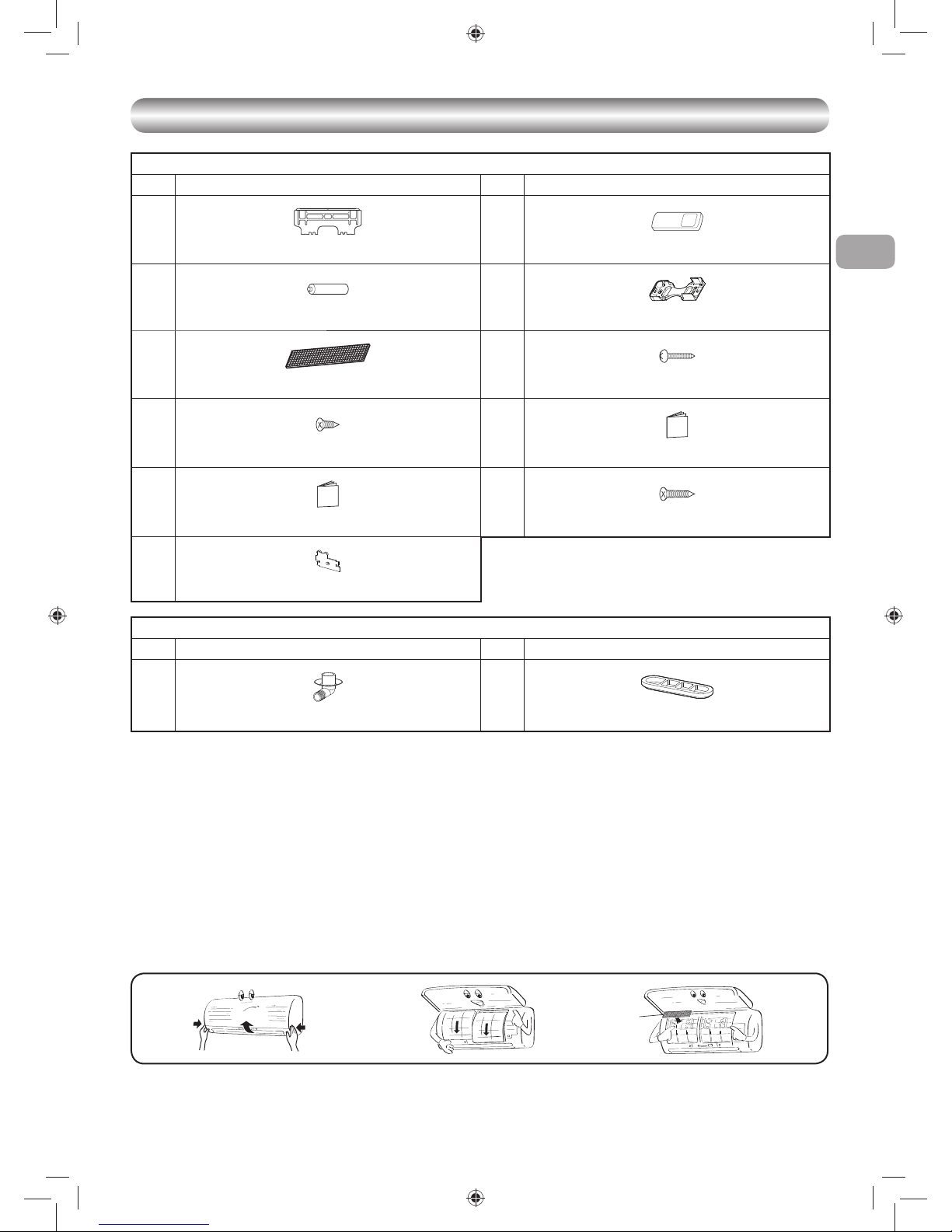
Indoor Unit
No. Part name No. Part name
1
Installation Plate × 1
2
Wireless remote control × 1
3
Battery × 2
4
Remote control holder × 1
5
Toshiba new IAQ fi lter × 1
6
Mounting screw × 6
7
Flat head wood screw × 2
8
Owner’s Manual × 1
9
Installation Manual × 1
!
Flat head wood screw × 1
"
Battery cover
Outdoor Unit
No. Part name No. Part name
#
Drain nipple × 1
$
Cap water proof × 2
Air fi lters
Clean every 2 weeks.
1. Open the air inlet grille.
2. Remove the air fi lters.
3. Vacuum or wash and then dry them.
4. Reinstall the air fi lters and close the air inlet grille.
Filter
Maintenance & Shelf-life
Clean every 3-6 months when dust tuck or covers the fi lter.
1. Recommend to use vacuum to clean by sucking the dusts which stick or dip inside the fi lter or use the blower to blow the dust go out through the fi lter.
2. If necessary to use water to clean, simply use the plain water to wash the fi lter, dry with the sunlight for 3-4 hours or until it completely dry.
Nevertheless, use hair drier to dry it. However, washing with water, it may reduce the performance of the fi lter.
3. Replace every 2 years or sooner. (contact your dealer to purchase new fi lter) (P/N : RB-A620DE)
Note: Filter life depends on the level of impurities in your operating environment. Higher levels of impurities may require more frequent cleaning and
replacement. In all cases, we recommend an additional set of fi lters to improve the purifying and deodorizing performance of your air conditioner.
Filter
01_1118350131-EN.indd 501_1118350131-EN.indd 5 2/10/2560 BE 10:06 AM2/10/2560 BE 10:06 AM

6
INSTALLATION DIAGRAM OF INDOOR AND OUTDOOR UNITS
INSTALLATION DIAGRAM OF INDOOR AND OUTDOOR UNITS
Part
code
Parts name Q’ty
A
Refrigerant piping
Liquid side : Ø6.35 mm
Gas side : Ø9.52 mm
(RAS-10, 13PKVSG-E)
: Ø12.70 mm
(RAS-16PKVSG-E)
One
each
B
Pipe insulating material
(polyethylene foam, 6 mm thick)
1
C
Putty, PVC tapes
One
each
Optional Installation Parts
• Secure the outdoor unit with fi xing bolts and nuts if the unit is likely to be
exposed to a strong wind.
• Use Ø8 mm or Ø10 mm anchor bolts and nuts.
• If it is necessary to drain the defrost water, attach drain nipple # and cap
water proof $ to the bottom plate of the outdoor unit before installing it.
Fixing bolt arrangement of outdoor unit
2
3
The auxiliary piping can be connected to
the left, rear left, rear right, right, bottom
right or bottom left.
Right
Rear
right
Bottom
right
Rear
left
Bottom left
Left
Insulate the refrigerant pipes separately
with insulation, not together.
6 mm thick heat resisting
polyethylene foam
1
Batteries
7
Flat head
wood screw
4
Remote control
holder
Vinyl tape
Apply after carrying
out a drainage test.
Wireless remote control
Saddle
Extension drain hose
(Not available, provided
by installer)
Shield pipe
(Attach to the front panel.)
Air fi lter
Hook
Installation
plate
Hook
65 mm or more
300 mm or more
300 mm or more
600 mm or more
100 mm or more
100 mm or more
600 mm or more
600 mm or more
Drain outlet
Air inlet
Air outlet
108 mm
28 mm
600 mm
320 mm
125 mm
86 mm
102 mm
90 mm
Ø25 mm
Insert the cushion between the indoor
unit and wall, and tilt the indoor unit for
better operation.
For the rear left and left piping
Wall
Make sure to run the drain hose sloped
downward.
Do not allow the drain hose to get slack.
Cut the piping
hole sloped
slightly.
The fl are connection should be installed
outdoors.
Refrigerant piping
must be protected from
physical damage.
Install a plastic cover or
equivalent.
The provided Remote Controller is a wireless
type, which also can be used as a wire.
Please see “How to Connect The Remote
Controller for Wired Operation”, in case of
wired control is required.
5
Filter
!
Flat head
wood screw
7
Flat head
wood screw
"
Battery
cover
01_1118350131-EN.indd 601_1118350131-EN.indd 6 2/10/2560 BE 10:06 AM2/10/2560 BE 10:06 AM
EN
ES
FR
IT
DE
PT
PL
CZ
RU
CR
HU
TR
NL
GR
SV
FI
NO
DK
RO
BG
EE
LV
SK
SI
7
6
INDOOR UNIT
INDOOR UNIT
Installation Place
• Direct sunlight to the indoor unit’s wireless receiver should be avoided.
• The microprocessor in the indoor unit should not be too close to RF
noise sources.
(For details, see the owner’s manual.)
Remote control
• A place where there are no obstacles such as a curtain that may block the
signal from the indoor unit
• Do not install the remote control in a place exposed to direct sunlight or
close to a heating source such as a stove.
• Keep the remote control at least 1 m apart from the nearest TV set or
stereo equipment. (This is necessary to prevent image disturbances or
noise interference.)
• The location of the remote control should be determined as shown below.
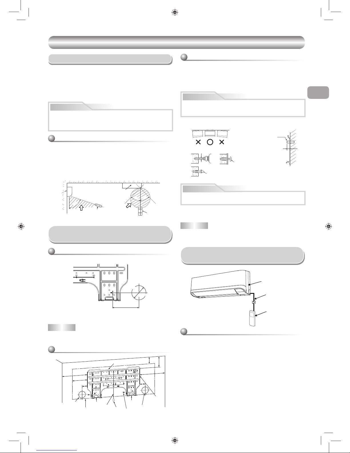
Cutting a Hole and Mounting
Installation Plate
NOTE
• When drilling a wall that contains a metal lath, wire lath or metal plate, be sure
to use a pipe hole brim ring sold separately.
Cutting a hole
When installing the refrigerant pipes from the rear
Mounting the installation plate
When the installation plate is directly mounted
on the wall
1. Securely fi t the installation plate onto the wall by screwing it in the upper and
lower parts to hook up the indoor unit.
2. To mount the installation plate on a concrete wall with anchor bolts, use the
anchor bolt holes as illustrated in the below fi gure.
3. Install the installation plate horizontally in the wall.
When installing the installation plate with a mounting screw, do not use the
anchor bolt holes. Otherwise, the unit may fall down and result in personal
injury and property damage.
1. After determining the pipe hole position on the mounting plate (
Æ), drill
the pipe hole (Ø65 mm) at a slight downward slant to the outdoor side.
• A place which provides the spaces around the indoor unit as shown in the
diagram
• A place where there are no obstacles near the air inlet and outlet
• A place which allows easy installation of the piping to the outdoor unit
• A place which allows the front panel to be opened
• The indoor unit shall be installed at least 2.5 m height. Also, it must be
avoided to put anything on the top of the indoor unit.
CAUTION
54 °
4
5°
5
7
°
(Side view) (Top view)
Indoor unit
Reception range
Remote
control
Remote
control
Reception
range
Indoor unit
CAUTION
Failure to fi rmly install the unit may result in personal injury and property
damage if the unit falls.
• In case of block, brick, concrete or similar type walls, make 5 mm dia.
holes in the wall.
• Insert clip anchors for appropriate mounting screws 6.
NOTE
• Secure four corners and lower parts of the installation plate with 4 to 6
mounting screws to install it.
CAUTION
The center of the pipe hole
is above the arrow.
Pipe hole
Ø65 mm
120 mm
Installation plate
(Keep horizontal direction.)
5 mm dia. hole
Clip anchor
(local parts)
Mounting screw
Ø4 x 25R
Anchor bolt
Projection
15 mm or less
144
50
50
300
65
103
300
6
1
Hook
Hook
Hook
Pipe hole
Pipe hole
Installation
plate
Mounting screw
Weight
Indoor unit
Thread
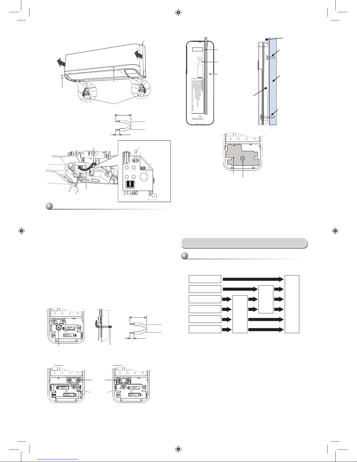
1 Open two screw caps and securely remove two screws at the front panel.
2. Slightly open the lower part of the front panel then pull the upper part of
the front panel toward you to remove it as shown on fi gure 1.
3. Arrange the control wire as detail and specifi cation as shown on fi gure
2.
4. Securely connect the control wire to terminal of Display unit as shown on
fi gure 3 (tighten fi rmly but not over 0.12 N·m (0.01 kgf·m)).
5. Set the control wire out from indoor unit same portion as power supply
and connecting cable as shown on fi gure 3. (Notch for wire out)
6. Reassembly the indoor unit by reverse process of 1 to 2.
Indoor unit
Control wire
Remote controller
How to Connect Remote Controller
for Wire Operation
For indoor unit
01_1118350131-EN.indd 701_1118350131-EN.indd 7 2/10/2560 BE 10:06 AM2/10/2560 BE 10:06 AM
8
Piping and Drain Hose Installation
* Since dewing results in a machine trouble, make sure to insulate both
connecting pipes. (Use polyethylene foam as insulating material.)
Piping and drain hose forming
1. Die-cutting back body slit
Cut out the slit on the left or right side of the back body for the left or right
connection and the slit on the bottom left or right side of the back body
for the bottom left or right connection with a pair of nippers.
Rear right
Rear left
Bottom left
Left
Bottom right
Right
Die-cutting
back body slit
Changing
drain hose
Piping preparation
2. Changing drain hose
For leftward connection, bottom-leftward connection and rearleftward
connection’s piping, it is necessary to change the drain hose and drain
cap.
1. Remove cover of remote controller by sliding down and take it out.
2. If batteries are exist, please take them out. The combination of using
wire controller and batteries may cause of batteries explosion.
3. Make hole for insert control wire by use screwdriver break the polyester
sheet as shown on fi gure 4.
4. Insert control wire from rear side of remote controller as shown on
fi gure 5.
5. Fix control wire which arrange as shown on fi gure 6 and 7 to terminal
by provided screws (tighten fi rmly but not over 0.25 N·m (0.03 kgf·m)).
6. Set control wire through gutter way at rear side of remote controller as
shown on fi gure 8.
7. Fix provided screw (Ø3.1×16L) on the wall to hang remote controller as
shown on fi gure 9.
8. Mark and arrange hole for fi x below screw (Ø3.1×25L) as shown on
fi gure 9.
9. Assembly battery cover which provided with accessory bag then use
provide screw (Ø3.1×25L) to fi x battery cover together with wall as
shown on fi gure ! (tighten fi rmly but not over 0.15 N·m (0.02 kgf·m)).
10. Reassembly cover of remote controller.
For remote controller
*Remark : 1. Recommend to use double insulation lead wire for connect
remote control and air conditioner.
2. For wire operation, 1 remote control can control only 1 indoor
unit.
3. In wire operation, remote controller will return to initial
condition (PRESET, TIMER and CLOCK will return to
initial condition) when user shutdown power supply of air
conditioner.
2
3
* Wire size 28-22AWG
or 0.08-0.32 mm
2
Outer diameter not over 4.7 mm,
control wire length 30 m. or less.
70 mm
5 mm
Terminal
Control wire
Notch for wire out
Control wire
Display unit
1
Screw
Screw cap
Screw
Front panel
Control wire
Hole for hang
remote controller
Remote controller
Control wire
Screw (Ø3.1×16L)
for hang remote
controller
Wall
Screw (Ø3.1×25L)
for fi x battery cover
Remote controller
89
!
Battery cover
Screw
Tighten fi rmly but not over
0.15 N·m (0.02 kgf·m)
45
Polyester sheet close hole
for insert control wire
Control wire
6
7
Control wire
Terminal
* Wire size 28-22AWG
or 0.08-0.32 mm
2
Outer diameter not over 4.7 mm,
control wire length 30 m. or less.
30 mm
10 mm
* Terminals for wiring can be either on right (type A) or left (type B), depending
on the controller packed in carton.
Type A Type B
01_1118350131-EN.indd 801_1118350131-EN.indd 8 2/10/2560 BE 10:06 AM2/10/2560 BE 10:06 AM
EN
ES
FR
IT
DE
PT
PL
CZ
RU
CR
HU
TR
NL
GR
SV
FI
NO
DK
RO
BG
EE
LV
SK
SI
9
4 mm
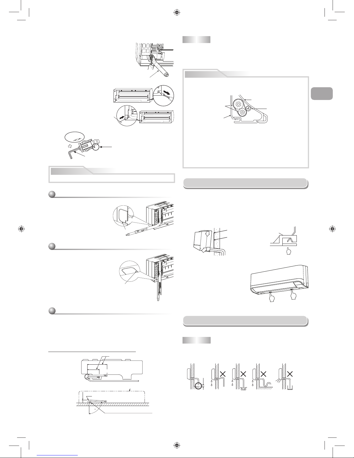
How to remove the drain cap
Clip the drain cap by needle-nose
pliers and pull out.
How to remove the drain hose
• The drain hose can be removed by removing the
screw securing the drain hose and then pulling out
the drain hose.
• When removing the drain hose, be careful of any
sharp edges of steel plate. The edges can injuries.
• To install the drain hose, insert the drain hose
fi rmly until the connection part contacts with heat
insulator, and then secure it with original screw.
How to fi x the drain cap
1) Insert hexagon wrench (4 mm)
in a center head.
2) Firmly insert the drain cap.
Firmly insert the drain hose and drain cap; otherwise, water may leak.
CAUTION
Do not apply lubricating oil
(refrigerant machine oil) when
inserting the drain cap. Application
causes deterioration and drain
leakage of the plug.
Insert a hexagon
wrench (4 mm).
No gap
Drain hose
Left-hand connection with piping
• Bend the connecting pipe so that it is laid within 43 mm above the wall
surface. If the connecting pipe is laid exceeding 43 mm above the wall
surface, the indoor unit may unstably be set on the wall.
When bending the connecting pipe, make sure to use a spring bender so
as not to crush the pipe.
Bend the connecting pipe within a radius of 30 mm.
To connect the pipe after installation of the unit (fi gure)
80
260 mm
210 mm
43 mm
Liquid side
Gas side
(To the forefront of fl are)
Outward form of indoor unit
R 30 mm (Use polisin (polyethylene)
core or the like for bending pipe.)
Use the handle of screwdriver, etc.
NOTE
If the pipe is bent incorrectly, the indoor unit may unstably be set on the wall.
After passing the connecting pipe through the pipe hole, connect the
connecting pipes to the auxiliary pipes and wrap the facing tape around
them.
In case of right or left piping
• After scribing slits of the back body
with a knife or a making-off pin, cut
them with a pair of nippers or an
equivalent tool.
In case of bottom right or bottom left piping
• After scribing slits of the back body
with a knife or a making-off pin, cut
them with a pair of nippers or an
equivalent tool.
Slit
Slit
CAUTION
• Bind the auxiliary pipes (two) and connecting cable with facing tape
tightly. In case of leftward piping and rear-leftward piping, bind the
auxiliary pipes (two) only with facing tape.
Indoor unit
Connecting cable
Auxiliary pipes
Installation plate
• Carefully arrange pipes so that any pipe does not stick out of the rear
plate of the indoor unit.
• Carefully connect the auxiliary pipes and connecting pipes to one
another and cut off the insulating tape wound on the connecting pipe to
avoid double-taping at the joint; moreover, seal the joint with the vinyl
tape, etc.
• Since dewing results in a machine trouble, make sure to insulate both
connecting pipes. (Use polyethylene foam as insulating material.)
• When bending a pipe, carefully do it, not to crush it.
Do not form the
drain hose into
a wavy shape.
Do not rise the
drain hose.
50 mm
or more
Do not put the
drain hose end
into water.
Do not put the
drain hose end
in the drainage ditch.
1
2
1
Hook here.
Installation plate
Hook
Press
(unhook)
Push
Push
Indoor Unit Fixing
• For detaching the indoor unit from
the installation plate, pull the indoor
unit toward you while pushing its
bottom up at the specifi ed parts.
1. Pass the pipe through the hole in the wall and hook the indoor unit on the
installation plate at the upper hook.
2. Swing the indoor unit to right and left to confi rm that it is fi rmly hooked up on
the installation plate.
3. While pressing the indoor unit onto the wall, hook it at the lower part on the
installation plate. Pull the indoor unit toward you to confi rm that it is fi rmly
hooked up on the installation plate.
Drainage
1. Run the drain hose sloped downwards.
NOTE
• The hole should be made at a slight downward slant on the outdoor side.
01_1118350131-EN.indd 901_1118350131-EN.indd 9 2/10/2560 BE 10:06 AM2/10/2560 BE 10:06 AM
10
Drain
guide
Space for pipes
Wall
Shield pipe
Inside the room
Drain hose
Extension drain hose
Arrange the drain pipe for proper drainage from the unit.
Improper drainage can result in dew-dropping.
This air conditioner has the structure designed
to drain water collected from dew, which forms
on the back of the indoor unit, to the drain pan.
Therefore, do not store the power cord and other
parts at a height above the drain guide.
CAUTION
OUTDOOR UNIT
OUTDOOR UNIT
Installation Place
• A place which provides the spaces around the outdoor unit as shown in
the diagram
• A place which can bear the weight of the outdoor unit and does not allow
an increase in noise level and vibration
• A place where the operation noise and discharged air do not disturb your
neighbors
• A place which is not exposed to a strong wind
• A place free of a leakage of combustible gases
• A place which does not block a passage
• When the outdoor unit is to be installed in an elevated position, be sure to
secure its feet.
• An allowable length of the connecting pipe is up to 20 m.
- There is no need to add refrigerant as long as the length of the
connection piping is 15 m or less.
- You will need to add 20g of refrigerant per meter of added connection
piping for installation requiring connection piping to be between 16 m to
20 m.
• The allowable height of outdoor-unit installation site is up to 12 m.
• A place where the drain water does not raise any problems
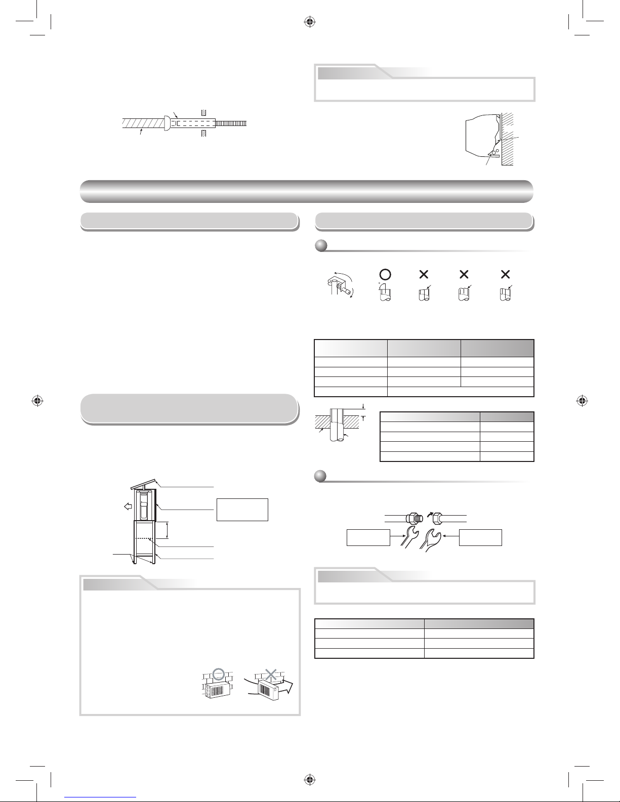
CAUTION
1. Install the outdoor unit without anything blocking the air discharging.
2. When the outdoor unit is installed in a place always exposed to strong
wind like a coast or on a high storey of a building, secure the normal fan
operation using a duct or a windshield.
3. In particularly windy areas, install the unit such as to avoid admission of
wind.
4. Installation in the following places may result in trouble.
Do not install the unit in such places.
• A place full of machine oil
• A saline-place such as the coast
• A place full of sulfi de gas
• A place where high-frequency
waves are likely to be generated
as from audio equipment, welders,
and medical equipment
Strong
wind
• Do not use the supplied drain nipple for draining water. Drain the water
from all the drain holes directly.
• To protect the outdoor unit from snow accumulation, install a holding
frame, and attach a snow protection hood and plate.
* Do not use a double-stacked design.
Precautions about Installation in Regions
with Snowfall and Cold Temperatures
Snow protection plate
Snow protection hood
Snow accumulation line
Holding frame
At least
50 cm
Install at least 50 cm
above the snow
accumulation line.
Anchor
bolts
Front
Flare nut
Half union
Externally
threaded side
Internally
threaded side
Use a wrench to secure. Use a torque wrench to tighten.
90
Obliquity Roughness Warp
CAUTION
Refrigerant Piping Connection
1. Cut the pipe with a pipe cutter.
2. Insert a fl are nut into the pipe and fl are the pipe.
• Projection margin in fl aring : A (Unit : mm)
RIDGID (clutch type)
IMPERIAL (wing nut type)
Outer dia. of copper pipe R32
Ø6.35 1.5 to 2.0
Ø9.52 1.5 to 2.0
Ø12.70 2.0 to 2.5
Pipes thickness 0.8 mm or more
Align the centers of the connecting pipes and tighten the fl are nut as far as pos-
sible with your fi ngers. Then tighten the nut with a spanner and torque wrench
as shown in the fi gure.
Tightening connection
Do not apply excess torque. Otherwise, the nut may crack depending on
the conditions.
(Unit : N·m)
Outer dia. of copper pipe Tightening torque
Ø6.35 mm 16 to 18 (1.6 to 1.8 kgf·m)
Ø9.52 mm 30 to 42 (3.0 to 4.2 kgf·m)
Ø12.70 mm 50 to 62 (5.0 to 6.2 kgf·m)
Outer dia.
of copper pipe
R32 tool used
Conventional tool
used
Ø6.35 0 to 0.5 1.0 to 1.5
Ø9.52 0 to 0.5 1.0 to 1.5
Ø12.70 0 to 0.5 1.0 to 1.5
Pipes thickness 0.8 mm or more
Flaring
A
Die
Pipe
2. Put water in the drain pan and make sure that the water is drained out of
doors.
3. When connecting extension drain hose, insulate the connecting part of
extension drain hose with shield pipe.
01_1118350131-EN.indd 1001_1118350131-EN.indd 10 2/10/2560 BE 10:06 AM2/10/2560 BE 10:06 AM
EN
ES
FR
IT
DE
PT
PL
CZ
RU
CR
HU
TR
NL
GR
SV
FI
NO
DK
RO
BG
EE
LV
SK
SI
11
Flare at
indoor unit side
Flare at
outdoor unit side
• Tightening torque of fl are pipe connections
The operating pressure of R32 is
higher than that of R22 (approx.
1.6 times). It is therefore necessary
to fi rmly tighten the fl are pipe
connecting sections (which connect
the indoor and outdoor units) up to the
specifi ed tightening torque. Incorrect
connections may cause not only a
gas leakage, but also damage to the
refrigeration cycle.
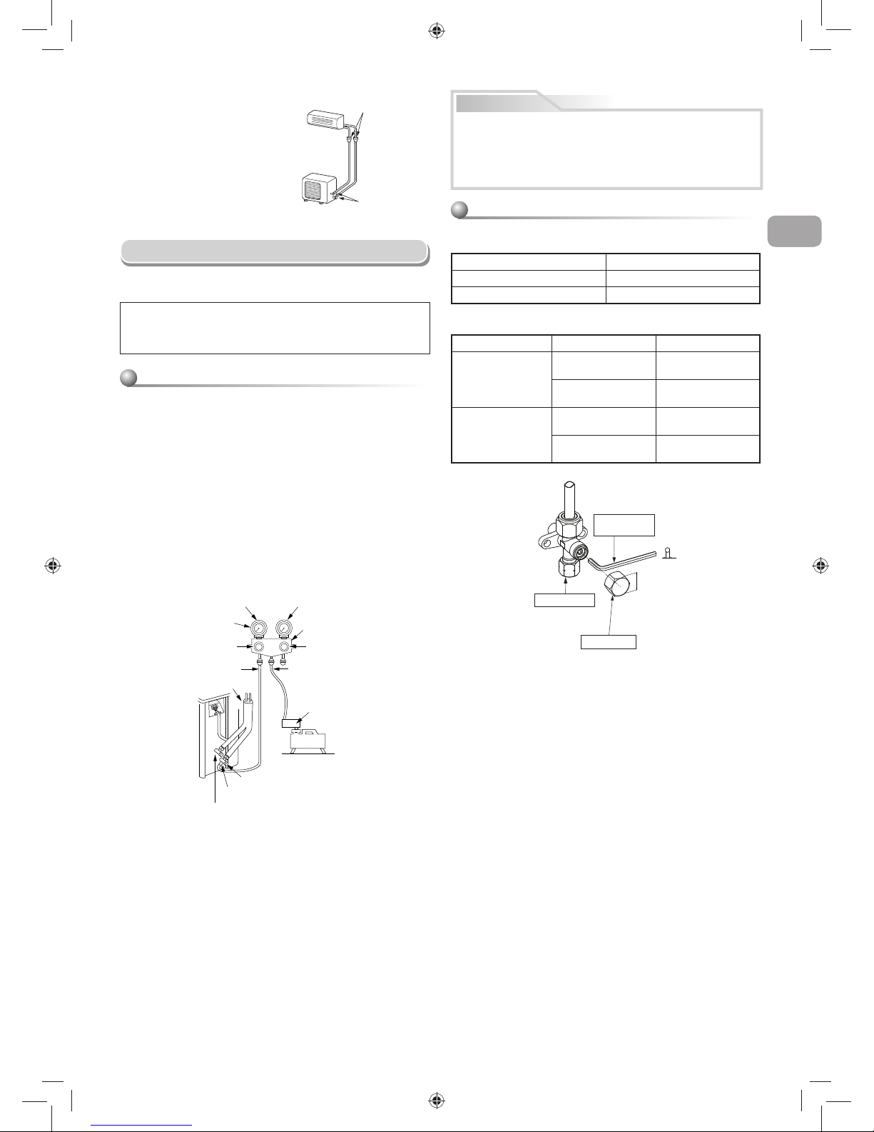
Evacuating
After the piping has been connected to the indoor unit, you can perform the
air purge together at once.
AIR PURGE
Evacuate the air in the connecting pipes and in the indoor unit using a
vacuum pump. Do not use the refrigerant in the outdoor unit. For details,
see the manual of the vacuum pump.
Be sure to use a vacuum pump with counter-fl ow prevention function so that
inside oil of the pump does not fl ow backward into pipes of the air conditioner
when the pump stops.
(If oil inside of the vacuum pump enters the air conditioner, which use R32,
refrigeration cycle trouble may result.)
1. Connect the charge hose from the manifold valve to the service port of the
packed valve at gas side.
2. Connect the charge hose to the port of the vacuum pump.
3. Open fully the low pressure side handle of the gauge manifold valve.
4. Operate the vacuum pump to start evacuating. Perform evacuating for
about 15 minutes if the piping length is 20 meters.
(15 minutes for 20 meters)
(assuming a pump capacity of 27 liters per minute) Then confi rm that the
compound pressure gauge reading is –101 kPa (–76 cmHg).
5. Close the low pressure side valve handle of the gauge manifold valve.
6. Open fully the valve stem of the packed valves (both gas and liquid sides).
7. Remove the charging hose from the service port.
8. Securely tighten the caps on the packed valves.
Using a vacuum pump
Packed valve at liquid side
Service port (Valve core (Setting pin))
Packed valve at gas side
Vacuum
pump
Vacuum pump adapter for
counter-fl ow prevention
Charge hose
Handle Hi
(Keep full closed)
Manifold valve
Pressure gauge
Compound pressure gauge
Handle Lo
Charge hose
Connecting pipe
–101 kPa
(–76 cmHg)
CAUTION
• KEEP IMPORTANT 5 POINTS FOR PIPING WORK.
(1) Take away dust and moisture (inside of the connecting pipes).
(2) Tighten the connections (between pipes and unit).
(3) Evacuate the air in the connecting pipes using a VACUUM PUMP.
(4) Check gas leak (connected points).
(5) Be sure to fully open the packed valves before operation.
Packed valve handling precautions
• Open the valve stem all the way out, but do not try to open it beyond the
stopper.
• Securely tighten the valve cap with torque in the following table:
Pipe size of Packed Valve Size of Hexagon wrench
12.70 mm and smallers A = 4 mm
15.88 mm A = 5 mm
Cap Cap Size (H) Torque
Valve Rod Cap
H17 - H19
14~18 N·m
(1.4 to 1.8 kgf·m)
H22 - H30
33~42 N·m
(3.3 to 4.2 kgf·m)
Service Port Cap
H14
8~12 N·m
(0.8 to 1.2 kgf·m)
H17
14~18 N·m
(1.4 to 1.8 kgf·m)
A
H
Hexagon wrench
is required.
Service Port Cap
Valve Rod Cap
01_1118350131-EN.indd 1101_1118350131-EN.indd 11 2/10/2560 BE 10:06 AM2/10/2560 BE 10:06 AM
12
ELECTRICAL WORKS
ELECTRICAL WORKS
The power supply can be selected to connect to indoor unit or outdoor unit. Choose proper way and connect the power supply and connecting cable by follow
the instruction as following.
Wiring Connection
Indoor unit Outdoor unit
Valve cover
Terminals block
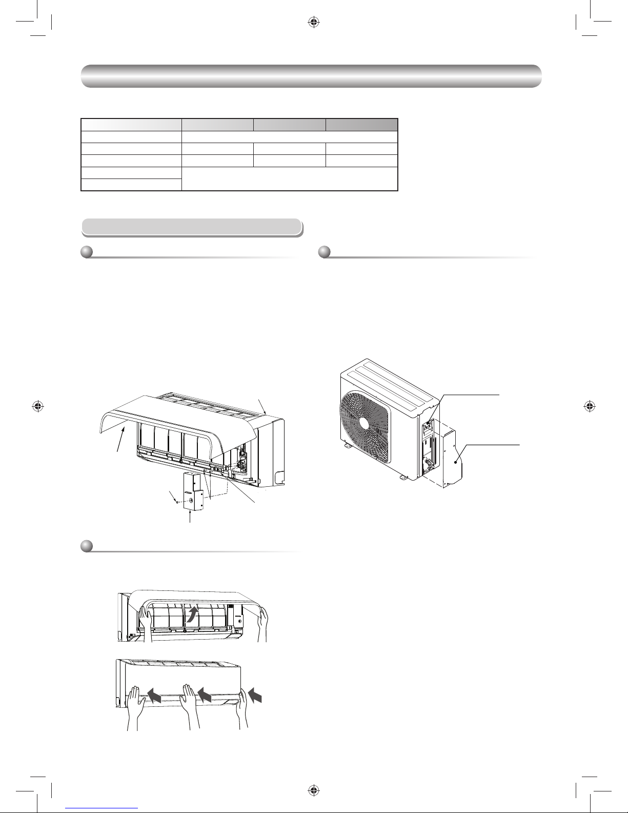
How to install the air inlet grille on the indoor
unit
• When attaching the air inlet grille, the contrary of the removed operation is
performed.
Wiring of the connecting cable can be carried out without removing the
front panel.
1. Remove the air inlet grille.
Open the air inlet grille upward and pull it toward you.
2. Remove the terminal cover and cord clamp.
3. Insert the connecting cable (according to the local cords) into the pipe hole
on the wall.
4. Take out the connecting cable through the cable slot on the rear panel so
that it protrudes about 20 cm from the front.
5. Insert the connecting cable fully into the terminal block and secure it tightly
with screws.
6. Tightening torque : 1.2 N·m (0.12 kgf·m)
7. Secure the connecting cable with the cord clamp.
8. Fix the terminal cover, rear plate bushing and air inlet grille on the indoor
unit.
Cord clamp
Terminal cover
Screw
Screws
Air inlet grille
Front panel
1. Remove the valve cover, the electric parts cover and the cord clamp from
the outdoor unit.
2. Connect the connecting cable to the terminal as identifi ed by the
matching numbers on the terminal block of indoor and outdoor unit.
3. Insert the power cord and the connecting cable carefully into the terminal
block and secure it tightly with screws.
4. Use vinyl tape, etc. to insulate the cords which are not going to be used.
Locate them so that they do not touch any electrical or metal parts.
5. Secure the power cord and the connecting cable with the cord clamp.
6. Attach the electric parts cover and the valve cover on the outdoor unit.
Model RAS-10PKVSG-E RAS-13PKVSG-E RAS-16PKVSG-E
Power source 50Hz, 220 – 240 V Single phase
Maximum running current 6.75A 7.35A 8.95A
Circuit breaker rating 8.5A 9.5A 11.5A
Power supply cable
H07RN-F or 60245 IEC66 (1.5 mm2 or more)
Connecting cable
01_1118350131-EN.indd 1201_1118350131-EN.indd 12 2/10/2560 BE 10:06 AM2/10/2560 BE 10:06 AM
EN
ES
FR
IT
DE
PT
PL
CZ
RU
CR
HU
TR
NL
GR
SV
FI
NO
DK
RO
BG
EE
LV
SK
SI
13
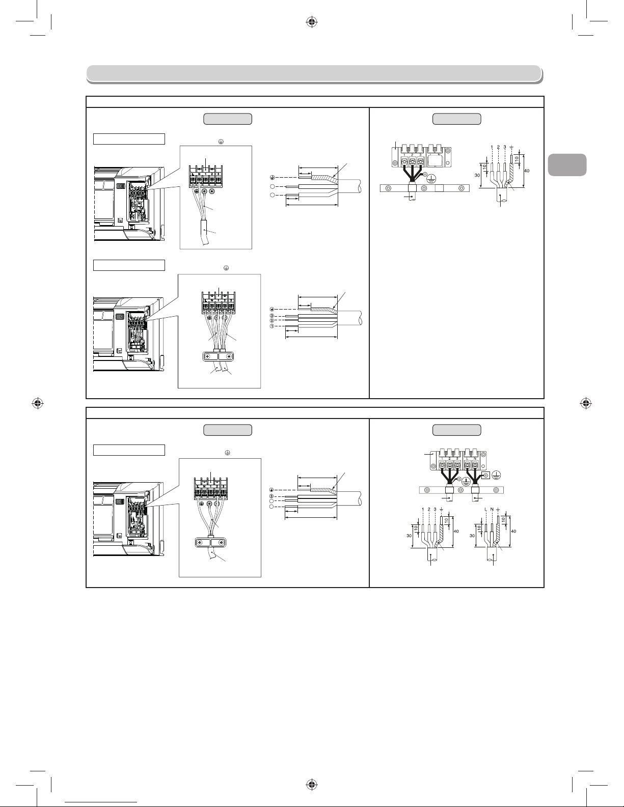
Power Supply Input at Indoor Unit Terminal Block (Recommend)
Indoor Unit Outdoor Unit
Power supply cable
connect to L N
Terminal block (L N 1 2 3)
Earth line
Power supply
cable
Power supply cable
Stripping length of the power
supply cable
N
L
Earth line
50 mm
10 mm
70 mm
10 mm
Connecting cable
Earth line
Connecting
cable
Terminal block
Connecting cable
connect to 1 2 3
Terminal block (L N 1 2 3)
Earth line
Power supply
cable
Connecting
cable
Earth line
Connecting cable
Stripping length of the
connecting cable
3
50 mm
Earth line
10 mm
70 mm
10 mm
Power Supply Input at Outdoor Unit Terminal Block (Optional)
Indoor Unit Outdoor Unit
Connecting cable
connect to L 2 3
Terminal block (L N 1 2 3)
Earth line
Connecting cable
Connecting cable
Stripping length of the
connecting cable
3
2
L
Earth line
50 mm
10 mm
70 mm
10 mm
Connecting cable
Earth line
Earth line
Connecting cable
Power cord
Terminal block
Power cord
Power Supply and Connecting Cable Connection
01_1118350131-EN.indd 1301_1118350131-EN.indd 13 2/10/2560 BE 10:06 AM2/10/2560 BE 10:06 AM
14
CAUTION
1. The power supply must be same as the rated of air conditioner.
2. Prepare the power source for exclusive use with air conditioner.
3. Circuit breaker must be used for the power supply line of this air conditioner.
4. Be sure to comply power supply and connecting cable for size and wiring method.
5. Every wire must be connected fi rmly.
6. Perform wiring works so as to allow a general wiring capacity.
7. Wrong wiring connection may cause some electrical part burn out.
8. Incorrect or incomplete wiring is carried out, it will cause an ignition or smoke.
9. This product can be connected to main power supply.
Connection to fi xed wiring : A switch which disconnects all poles and has a contact separation at least 3 mm must be incorporated in the fi xed wiring.
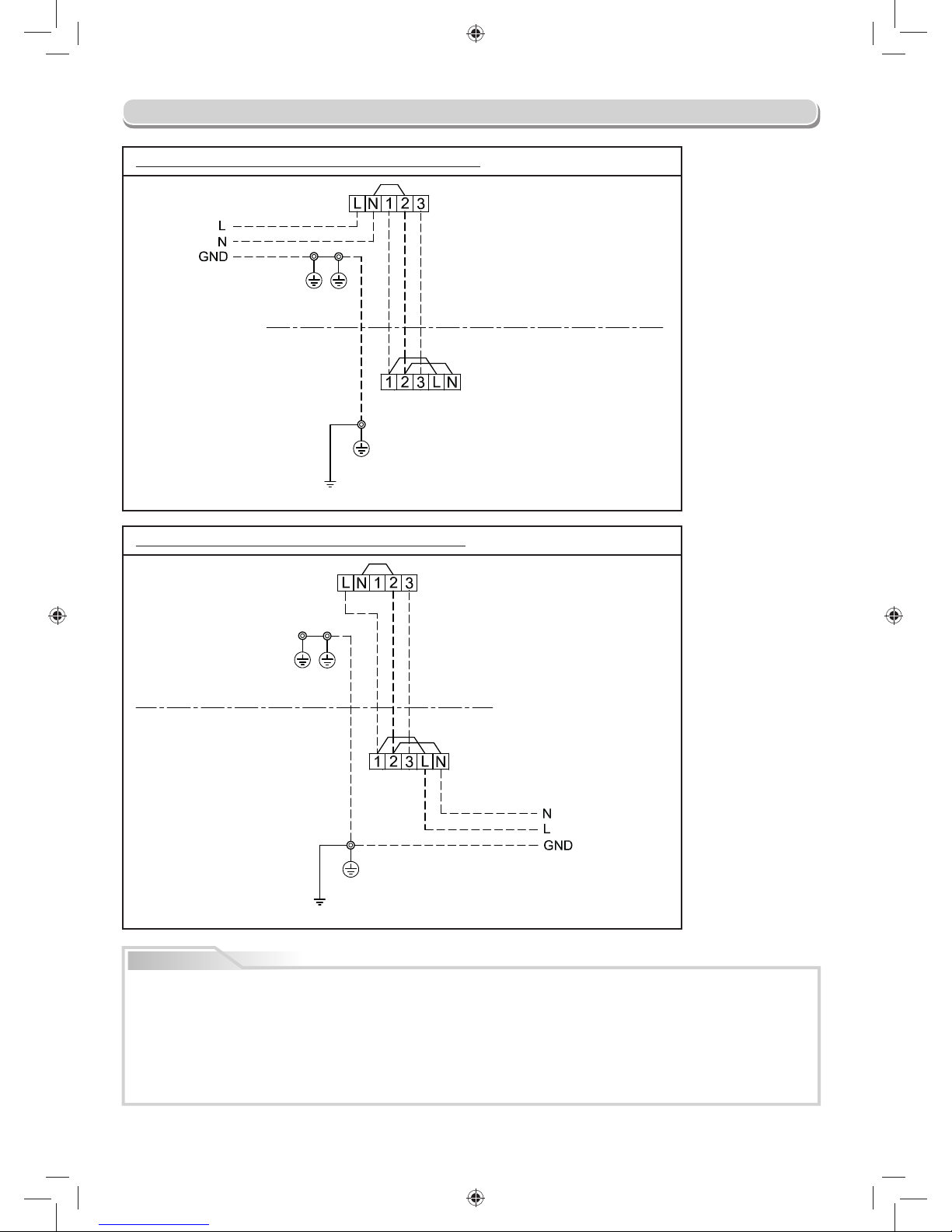
Power supply input at Indoor unit Terminal Block (Recommend)
Indoor
Terminal
Block
Power supply
input
Outdoor
Terminal
Block
INDOOR UNIT
OUTDOOR UNIT
CHASSIS
CHASSIS
EARTH
Power supply input at Outdoor unit Terminal Block (Optional)
Indoor
Terminal
Block
Power supply
input
Outdoor
Terminal
Block
INDOOR UNIT
OUTDOOR UNIT
CHASSIS
CHASSIS
EARTH
Power supply input Wiring Diagram
01_1118350131-EN.indd 1401_1118350131-EN.indd 14 2/10/2560 BE 10:06 AM2/10/2560 BE 10:06 AM
EN
ES
FR
IT
DE
PT
PL
CZ
RU
CR
HU
TR
NL
GR
SV
FI
NO
DK
RO
BG
EE
LV
SK
SI
15
OTHERS
OTHERS
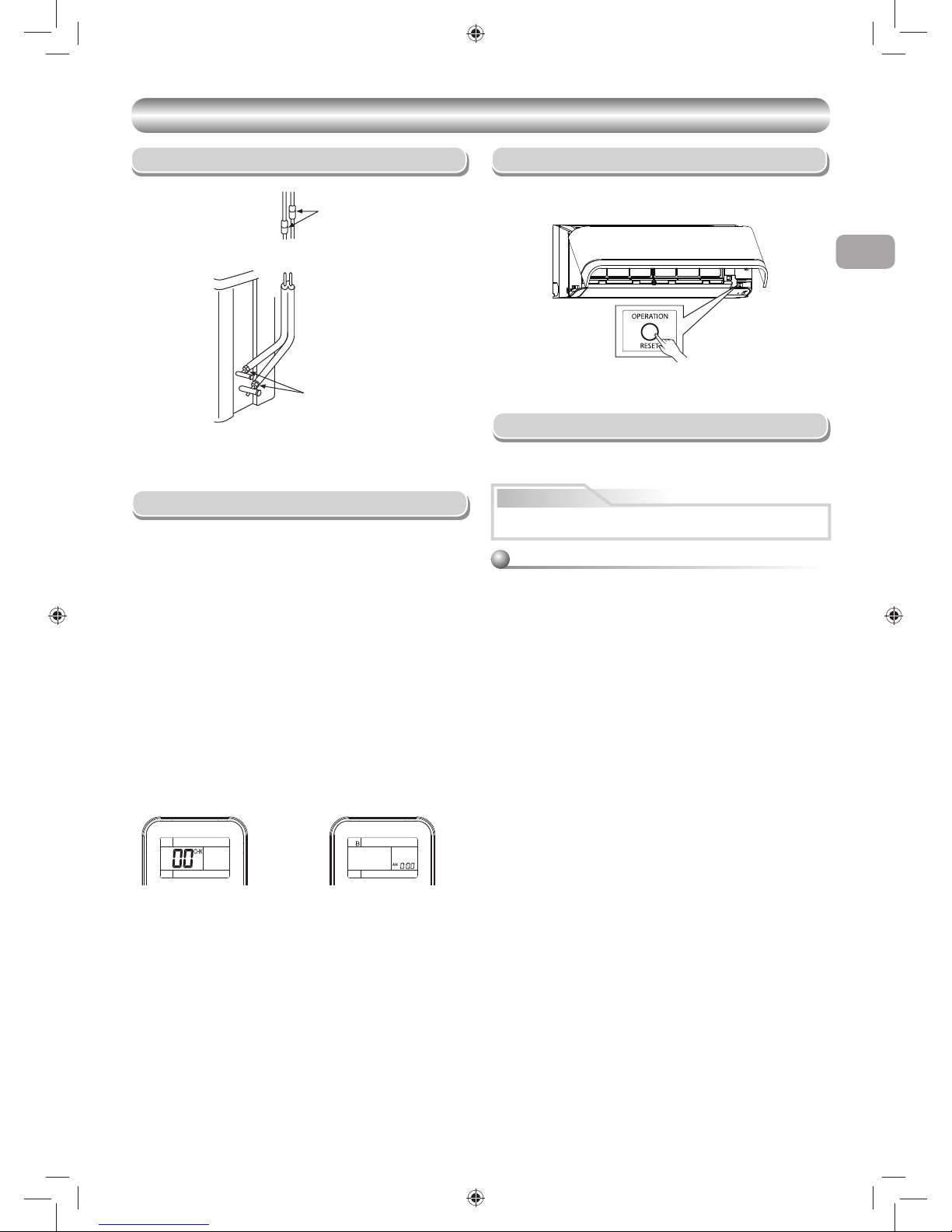
Gas Leak Test
Remote Control A-B Selection
To separate using of remote control for each indoor unit in case of 2 air
conditioner are installed near.
Remote Control B Setup.
1. Press [RESET] button on the indoor unit to turn the air conditioner ON.
2. Point the remote control at the indoor unit.
3. Push and hold [CHECK] button on the Remote Control by the tip of the
pencil. “00” will be shown on the display (Picture 1).
4. Press [MODE] during pushing [CHECK]. “B” will show on the display
and “00” will disappear and the air conditioner will turn OFF. The Remote
Control B is memorized (Picture 2).
Note : 1. Repeat above step to reset Remote Control to be A.
2. Remote Control A have not “A” display.
3. Default setting of Remote Control from factory is A.
• Check the fl are nut connections for the gas leak with a gas leak detector
or soap water.
Check places for
the indoor unit.
Check places for
the outdoor unit.
• When two indoor units are installed in the same room or adjacent two
rooms, if operating a unit, two units may receive the remote control signal
simultaneously and operate. In this case, the operation can be preserved
by setting either one remote control to B setting. (Both are set to A setting
in factory shipment.)
• The remote control signal is not received when the settings of indoor unit
and remote control are different.
• There is no relation between A setting/B setting and A room/B room when
connecting the piping and cables.
12
Test Operation
To switch the TEST RUN (COOL) mode, press [RESET] button for
10 seconds. (The beeper will make a short beep.)
Auto Restart Setting
The product was shipped with Auto Restart function in the off position.
Turn it on as required.
This product is designed so that, after a power failure, it can restart automatically
in the same operating mode as before the power failure.
Information
How to set the Auto Restart
1. Press and hold the [RESET] button on the indoor unit for 3 seconds to
set the operation. (3 beep sound and OPERATION lamp blink 5 time/sec
for 5 seconds)
2. Press and hold the [RESET] button on the indoor unit for 3 seconds to
cancel the operation. (3 beep sound but OPERATION lamp does not
blink)
• In case of ON timer or OFF timer are set, AUTO RESTART
OPERATION does not activate.
OPERATION /
RESET Button
01_1118350131-EN.indd 1501_1118350131-EN.indd 15 2/10/2560 BE 10:06 AM2/10/2560 BE 10:06 AM
16
APPENDIX
APPENDIX
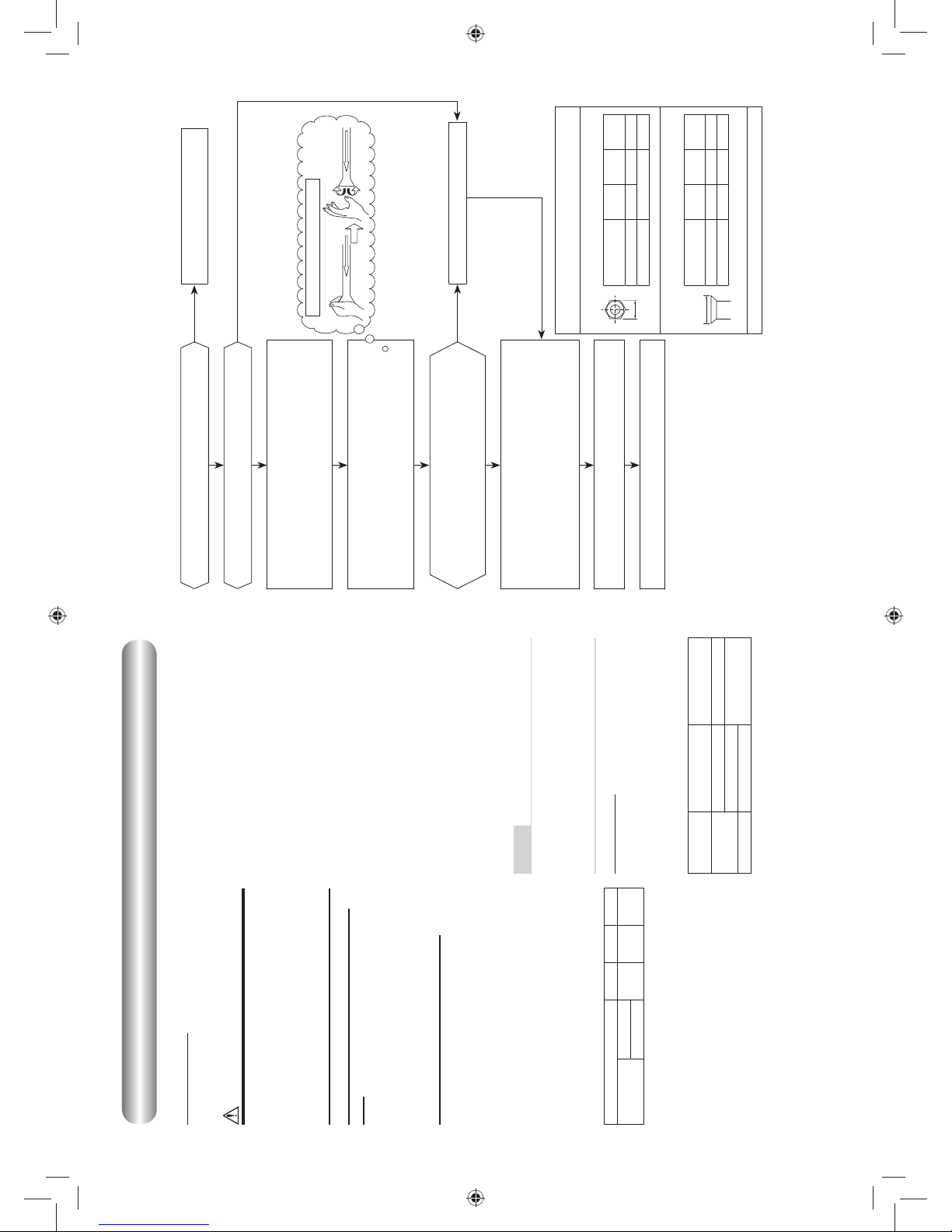
Work instructions
The existing R22 and R410A piping can be reused for
inverter R32 product installations.
WARNING
Confirming the existence of scratches or dents on
the existing pipes and confirming the reliability of
the pipe strength are conventionally referred to the
local site.
If the specified conditions can be cleared, it is
possible to update existing R22 and R410A pipes
to those for R32 models.
Basic conditions needed to reuse existing
pipes
Check and observe the presence of three conditions in
the refrigerant piping works.
1. Dry (There is no moisture inside of the pipes.)
2. Clean (There is no dust inside of the pipes.)
3. Tight (There are no refrigerant leaks.)
Restrictions for use of existing pipes
In the following cases, the existing pipes should
not be reused as they are. Clean the existing pipes
or exchange them with new pipes.
1. When a scratch or dent is heavy, be sure to use new
pipes for the refrigerant piping works.
2. When the existing pipe thickness is thinner than the
specified “Pipe diameter and thickness,” be sure to
use new pipes for the refrigerant piping works.
y The operating pressure of R32 is high (1.6 times
that of R22). If there is a scratch or dent on the pipe
or a thinner pipe is used, the pressure strength may
be inadequate, which may cause the pipe to break
in the worst case.
* Pipe diameter and thickness (mm)
Pipe outer diameter Ø6.4 Ø9.5 Ø12.7
Thickness
R32, R410A
0.8 0.8 0.8
R22
3. When the outdoor unit was left with the pipes
disconnected, or the gas leaked from the pipes and
the pipes were not repaired and refilled.
y There is the possibility of rain water or air, including
moisture, entering the pipe.
4. When refrigerant cannot be recovered using a
refrigerant recovery unit.
y There is the possibility that a large quantity of dirty
oil or moisture remains inside the pipes.
5. When a commercially available dryer is attached to the
existing pipes.
y There is the possibility that copper green rust has
been generated.
6. When the existing air conditioner is removed after
refrigerant has been recovered.
Check if the oil is judged to be clearly different from
normal oil.
y The refrigerator oil is copper rust green in color:
There is the possibility that moisture has mixed with
the oil and rust has been generated inside the pipe.
y There is discolored oil, a large quantity of residue,
or a bad smell.
y A large quantity of shiny metal dust or other wear
residue can be seen in the refrigerant oil.
7. When the air conditioner has a history of the
compressor failing and being replaced.
y When discolored oil, a large quantity of residue,
shiny metal dust, or other wear residue or mixture of
foreign matter is observed, trouble will occur.
8. When temporary installation and removal of the air
conditioner are repeated such as when leased etc.
9. If the type of refrigerator oil of the existing air
conditioner is other than the following oil (Mineral oil),
Suniso, Freol-S, MS (Synthetic oil), alkyl benzene
(HAB, Barrel-freeze), ester series, PVE only of ether
series.
y The winding-insulation of the compressor may
deteriorate.
NOTE
The above descriptions are results have been confirmed
by our company and represent our views on our air
conditioners, but do not guarantee the use of the existing
pipes of air conditioners that have adopted R32 in other
companies.
Curing of pipes
When removing and opening the indoor or outdoor unit for
a long time, cure the pipes as follows:
y Otherwise rust may be generated when moisture or
foreign matter due to condensation enters the pipes.
y The rust cannot be removed by cleaning, and new
pipes are necessary.
Placement
location
Term Curing manner
Outdoors
1 month or more Pinching
Less than 1 month
Pinching or taping
Indoors Every time
Are there scratches or dents on the existing pipes?
Is it possible to operate the existing air conditioner?
y After the existing air conditioner is operated in cooling
mode for approx. 30 minutes or longer,* recover the
refrigerant.
y For cleaning the pipes and recovering oil
y Refrigerant recovery: Pump down method
y Remove the existing air conditioner from the piping
and carry out flushing (nitrogen pressure 0.5 MPa) to
remove any remains inside of the pipe.
Note: In case of twin pipes, also be sure to flush the
branching pipe.
Connect the indoor / outdoor units to the existing pipe.
y Use a flare nut attached to the main unit for the indoor
/ outdoor units. (Do not use the flare nut of the existing
pipe.)
y Re-machine the flare machining size to size for R32.
y (Airtight test), Vacuum dry, Refrigerant charge, Gas
leak check
Test run
Was largely discolored oil or a large quantity
of remains discharged? (When the oil deteriorates,
the color of the oil changes to a muddy
or black color.)
Existing pipes: Cannot be used.
y Use new pipes.
Clean the pipes or use new pipes.
Piping necessary to change the flare nut / machining
size due to pipe compression
1) Flare nut width: H
H
(mm)
Copper pipe
outer diameter
Ø6.4 Ø9.5 Ø12.7
For R32, R410A 17 22 26
For R22 Same as above 24
2) Flare machining size: A
A
(mm)
Copper pipe
outer diameter
Ø6.4 Ø9.5 Ø12.7
For R32, R410A 9.1 13.2 16.6
For R22 9.0 13.0 16.2
Becomes a little larger for R32
Do not apply refrigerator oil to the flare surface.
(If there is discharge of remains, it is judged that a
large quantity of remains are present.)
YES
YES
NO
NONOYES
Nitrogen gas pressure 0.5 MPa
01_1118350131-EN.indd 1601_1118350131-EN.indd 16 2/10/2560 BE 10:06 AM2/10/2560 BE 10:06 AM
1
ES
PRECAUCIONES SOBRE SEGURIDAD
PRECAUCIONES SOBRE SEGURIDAD
•
Antes de la instalación, por favor lea con atención estas precauciones de seguridad.
• Asegúrese de seguir las precauciones proporcionadas aquí para evitar riesgos
de seguridad. Abajo aparecen los símbolos y sus signifi cados.
ADVERTENCIA : Indica que un uso incorrecto de esta unidad podría causar
lesiones importantes o la muerte.
PRECAUCIÓN : Indica que un uso incorrecto de esta unidad podría causar
lesiones personales (*1), o daños materiales (*2).
*1: Una lesión personal signifi ca un pequeño accidente, golpe,
o descarga eléctrica que no requiera un ingreso a hospital
o un tratamiento continuo.
*2: Un daño material es un daño mayor que afecta a activos o
recursos.
Para el uso público general
El cable de alimentación y el cable de conexión del sistema debe ser al menos
cable fl exible enfundado en policloropreno (modelo H07RN-F) o del tipo 60245
IEC66. (Debe instalarse según las normas de instalación eléctrica de cada país.)
Este aparato debe conectarse al suministro eléctrico mediante un disyuntor o un
interruptor que disponga de una separación de contacto de 3 mm como mínimo
en todos los polos.
PRECAUCIÓN
Para desconectar el aparato de la alimentación principal
Lea las precauciones en este
manual atentamente antes de
poner en funcionamiento la unidad.
Este dispositivo está lleno con
R32.
02_1118350131-ES.indd 102_1118350131-ES.indd 1 2/14/2560 BE 2:10 PM2/14/2560 BE 2:10 PM
2
ADVERTENCIA
• Nunca modifi que esta unidad quitando uno de las etiquetas de seguridad o
puenteando uno de los interruptores de interbloqueo de seguridad.
• No instale esta unidad en un lugar que no sea capaz de resistir el peso de la
unidad.
Si la unidad se cayera podría causar daños personales o materiales.
•
Antes de hacer un trabajo eléctrico, instale un enchufe aprobado al cable de
suministro de alimentación.
Y asegúrese de que el equipo está conectado a tierra.
• El aparato deberá instalarse según las regulaciones de cableado nacional.
Si detectara algún daño, no instale la unidad. Póngase en contacto con su
concesionario inmediatamente.
PELIGRO
• SOLAMENTE PARA EL USO DE PERSONAS CUALIFICADAS.
• DESACTIVE LA FUENTE DE ALIMENTACIÓN PROVISTA Y EL
CORTACIRCUITOS ANTES DE INTENTAR REALIZAR CUALQUIER TRABAJO
ELÉCTRICO. ASEGURESE DE QUE TODOS LOS INTERRUPTORES DE
ALIMENTACIÓN Y CORTACIRCUITOS ESTÉN DESACTIVADOS, SI NO LO
HACE PODRÍA CAUSAR DESCARGAS ELÉCTRICAS.
• CONECTE EL CABLE DE CONEXIÓN CORRECTAMENTE. SI ESTE CABLE
FUESE CONECTADO ERRONEAMENTE, SE PODRÍAN DAÑAR LAS PARTES
ELÉCTRICAS.
• REVISE EL CABLE A TIERRA QUE NO ESTE ROTO NI DESCONECTADO
ANTES DE LA INSTALACIÓN.
• NO INSTALE CERCA DE CONCENTRACIONES DE COMBUSTIBLE DE GAS
O VAPORES DE GAS.
SI FALLA EN CUMPLIR CON ESTA INSTRUCCION PODRIA RESULTAR EN
UN INCENDIO O UNA EXPLOSIÓN.
• PARA EVITAR EL RECALENTAMIENTO DE LA UNIDAD INTERIOR Y LA
CAUSA DE POSIBLES INCENCIOS, COLOQUE LA UNIDAD BIEN LEJOS
(A MÁS DE 2 METROS) DE FUENTES DE CALEFACCIÓN TALES COMO
RADIADORES, CALEFACTORES, ESTUFAS, HORNOS, ETC.
• CUANDO MUEVA EL ACONDICIONADOR DE AIRE PARA INSTALARLO EN
OTRO LUGAR, TENGA CUIDADO DE NO OBTENER EL REFRIGERANTE
ESPECIFICADO (R32) CON ALGUN OTRO CUERPO GASEOSO EN EL CICLO
DE REFRIGERACIÓN. SI EL AIRE O ALGUN OTRO GAS SE MEZCLARA
CON EL REFRIGERANTE, LA PRESIÓN DEL GAS EN EL CICLO DE
REFRIGERACIÓN SE VUELVE ANORMALMENTE ALTA Y ESTO RESULTANDO
EN CAUSAR UN ESTALLIDO DE LA TUBERÍA Y DAÑOS EN LAS PERSÓNAS.
• EN EL CASO DE QUE EL GAS REFRIGERANTE ESCAPARA DE LA TUBERÍA
DURANTE EL TRABAJO DE INTALACIÓN, INMEDIATAMENTE DEJE QUE
PASE AIRE FRESCO EN LA HABITACIÓN. SI ESTE GAS REFRIGERANTE
ES CALENTADO POR EL FUEGO O ALGO SIMILAR, CAUSARA LA
GENERACIÓN DE UN GAS VENENOSO.
02_1118350131-ES.indd 202_1118350131-ES.indd 2 2/14/2560 BE 2:10 PM2/14/2560 BE 2:10 PM
3
ES
• No utilice ningún refrigerante distinto al especifi cado para rellenar o reemplazar.
De lo contrario, podrá generarse una presión anormalmente alta en el ciclo de
refrigeración, lo cual puede producir roturas o explosión, además de lesiones.
• No utilice medios para acelerar el proceso de descongelación o para limpiar,
diferentes a los recomendados por el fabricante.
• El dispositivo se tiene que guardar en una habitación sin fuentes de ignición en
funcionamiento continuamente (por ejemplo: llamas abiertas, aparato de gas o
un calentador eléctrico en funcionamiento.
• Tenga en cuenta que los refrigerantes no pueden tener un olor.
• No perfore ni queme ya que el dispositivo está presurizado. No exponga el
aparato al calor, llamas, chispas, u otras fuentes o a ignición. De lo contrario,
puede explotar y causar lesiones o la muerte.
• Para el modelo R32, utilice tubos, tuerca abocinada y herramientas que se
especifi can para el refrigerante R32. Utilizar tuberías existentes (R22), tuerca
abocinada y herramientas pueden causar alta presión anormal en el ciclo del
refrigerante (tuberías) y posiblemente provocar explosiones y lesiones.
• El espesor de tubos de cobre usados R32 debe ser superior a los 0,8 mm. No
utilice nunca tuberías de cobre más fi nas de 0,8 mm.
• No realice la conexión abocindada dentro de un edifi cio o vivienda o habitación,
al unir el intercambiador de calor de la unidad interior con una tubería de
interconexión.
La conexión de refrigerante dentro de un edifi cio o vivienda o habitación debe
hacerse por soldadura. La conexión común de unidad interior por el método
de ensanchamiento sólo puede realizarse al aire libre o fuera de un edifi cio o
vivienda o habitación. La conexión abocinada puede causar fugas de gas y
atmósfera infl amable.
• Después de la terminación de la instalación o servicio, confi rme que no hay
fugas de gas refrigerante. Puede generar gases tóxicos cuando el refrigerante
contacte con fuego.
• El dispositivo y el trabajo en tubería debería ser insalado, operado y
almacenado en una sala con una superfi cie de suelo más grande de A
min
m2.
Cómo obtener A
min
m2 : A
min
= (M / (2,5 x 0,22759 x h0))
2
M es la cantidad de carga de refrigerante en el dispositivo en kg. h0 es la altura
de instalación del dispositivo en m: 0,6 m para estar sobre el suelo/1,8 m para
montar en la pared /1,0 m para montar en la ventana /2,2 para montar en el
techo (Altura de instalación recomendada para estas unidades 2,5 m.).
• Cumplir con las regulaciones nacionales sobre gas.
02_1118350131-ES.indd 302_1118350131-ES.indd 3 2/14/2560 BE 2:10 PM2/14/2560 BE 2:10 PM
4
INFORMACIÓN NECESARIA PARA EL SUMINISTRADOR DE
ALIMENTACIÓN LOCAL
Antes de instalar este sistema de aire acondicionado, no olvide informar de ello al
suministrador de alimentación local. Si surge algún problema o el suministrador de
alimentación no acepta la instalación, el sistema de asistencia tomará las medidas
correctoras necesarias.
■
Información importante relativa al refrigerante utilizado.
Este producto contiene gases hivernadero fl uorados.
No ventile gases a la atmósfera.
Tipo de refrigerante: R32
Valor PCA
(1)
: 675 * (p.ej. R32 ref. AR4)
(1)
PCA = potencial de calentamiento atmosférico
La cantidad de refrigerante está indicada en la placa de identifi cación del equipo.
* Este valor está basado en la regulación de gas F 517/2014
• La exposición de la unidad al agua o a cualquier otro tipo de humedad antes de
la instalación puede provocar un cortocircuito.
No almacene la unidad en un sótano mojado, ni la exponga a la lluvia ni al agua.
• Después de desembalajar la unidad, examínela cuidadosamente para ver si hay
alguna avería.
• No instale la unidad en un lugar donde pueda haber fugas de gas infl amable.
En caso de fugas de gas y que se acumula alrededor de la unidad, puede haber
un incendio.
• No instale la unidad en un lugar que pueda aumentar la vibración de la misma.
Tampoco la instale en un lugar que pueda amplifi car el nivel de ruido de la
unidad, o donde el ruido y el aire descargado puedan molestar a los vecinos.
• Para evitar daños personales, tenga cuidado cuando maneje las partes con
bordes afi lados.
• Lea el manual de instalación a fondo antes de instalar la unidad. El manual
contiene instrucciones importantes para la instalación correcta.
• El fabricante no asume responsabilidad alguna por los daños que resulten de la
falta de observación de las descripciones de este manual.
PRECAUCIÓN
02_1118350131-ES.indd 402_1118350131-ES.indd 4 2/14/2560 BE 2:10 PM2/14/2560 BE 2:10 PM
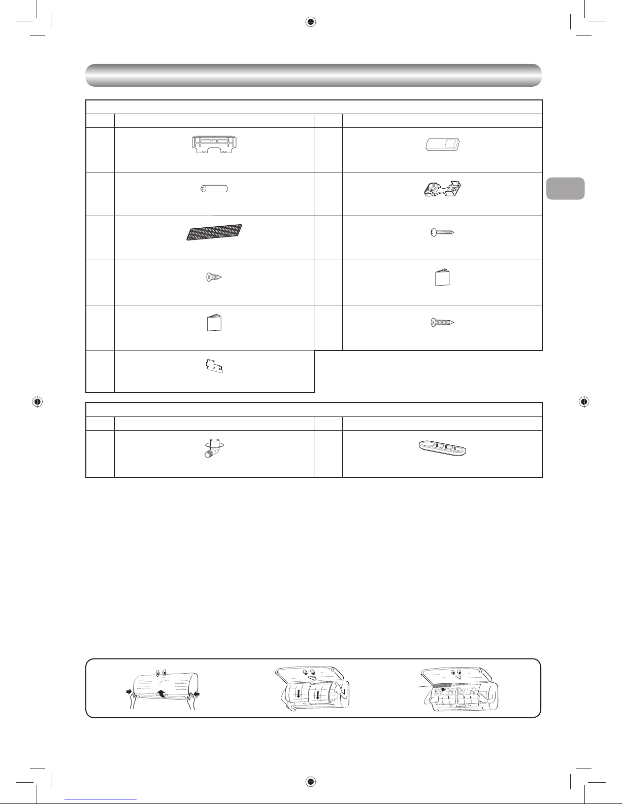
5
ES
ACCESSORIOS
ACCESSORIOS
Unidad Interior
N° Nombre de partes N° Nombre de partes
1
Placa de instalación × 1
2
Control remoto × 1
3
Pila × 2
4
Soporte del control remoto × 1
5
Nuevo fi ltro Toshiba IAQ × 1
6
Tornillo de montaje × 6
7
Tornillo de cabeza plana de madera × 2
8
Manual del usuario × 1
9
Manual de Instalación × 1
!
Tornillo de cabeza plana de madera × 1
"
Tapa de la pila
Unidad Exterior
N° Nombre de partes N° Nombre de partes
#
Codo de drenaje × 1
$
Tapa impermeable × 2
AFiltros de aire
Limpiar cada 2 semanas.
1. Abra la rejilla de la toma de entrada de aire.
2. Retire los fi ltros de aire.
3. Aspírelos o lávelos y, después, séquelos.
4. Vuelva a instalar los fi ltros y cierre la rejilla de la toma de entrada de aire.
Filtro
Mantenimiento y vida útil
Límpielo cada 3-6 meses cuando se acumule el polvo o cubra el fi ltro.
1. Se recomienda usar un aspirador para aspirar el polvo que se quede pegado o que se encuentre en el interior del fi ltro, o utilice el soplador para
soplar el polvo a través del fi ltro.
2. Si fuese necesario usar agua para la limpieza, utilice simplemente agua normal para lavar el fi ltro, déjelo secar al sol durante 3-4 horas o hasta
quedar completamente seco. Sin embargo, utilice un secador para secarlo. Tenga en cuenta que lavarlo con agua puede reducir el rendimiento del
fi ltro.
3. Sustitúyalo cada 2 años o menos. (Contacte a su distribuidor para adquirir un fi ltro nuevo.) (P/N : RB-A620DE)
Nota: La vida útil del fi ltro depende del nivel de impurezas existente en el entorno de funcionamiento. Si los niveles de impureza s son elevados, tal vez sea
necesario realizar la limpieza y el reemplazo con mayor frecuencia. En todos los casos, se recomienda adquirir un conjunto adicional de fi ltros para
mejorar el rendimiento de purifi cación y desodorización del aparato de aire acondicionado.
Filtro
02_1118350131-ES.indd 502_1118350131-ES.indd 5 2/14/2560 BE 2:10 PM2/14/2560 BE 2:10 PM
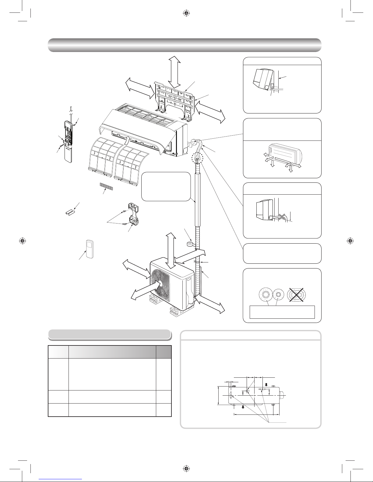
6
2
3
1
Pilas
7
Tornillo de cabeza
plana de madera
4
Soporte del
control remoto
Cinta de vinilo
Aplíquela después de realizar
una prueba de drenaje.
Control remoto
Apoyo
Manguera de drenaje
de extensión
(No disponible,
suministrado por el
instalador)
Protección de
la tubería
(Instale en el panel frontal.)
Filtro de aire
Gancho
Placa de
instalación
Gancho
65 mm o más
300 mm o más
300 mm o más
600 mm o más
100 mm o más
100 mm o más
600 mm o más
600 mm o más
DIAGRAMA DE INSTALACIÓN DE LA UNIDAD INTERIOR Y EXTERIOR
DIAGRAMA DE INSTALACIÓN DE LA UNIDAD INTERIOR Y EXTERIOR
Código
de pieza
Nombre de partes Ctdad.
A
Tubería de refrigerante
Lado líquido : Ø6,35 mm
Lado de gas : Ø9,52 mm
(RAS-10, 13PKVSG-E)
: Ø12,70 mm
(RAS-16PKVSG-E)
Cada
uno
B
Material aislante de tuberías
(espuma de polietileno de 6 mm de grosor)
1
C
Masilla, cintas de PVC
Cada
uno
Piezas de Instalación Opcional
• Proteja la unidad exterior con los tornillos y tuercas de fi jación si va a
permanecer expuesta a la acción de vientos fuertes.
• Utilice tornillos y tuercas de anclaje de Ø8 mm o Ø10 mm.
• Si fuera necesario vaciar el agua descongelada, conecte el codo de drenaje
# y la tapa impermeable $ en la placa inferior de la unidad exterior antes
de instalarla.
Fijación de tornillos de la unidad exterior
La tubería auxiliar se podrá conectar
al lado izquierdo, posterior izquierdo,
posterior derecho, derecho, inferior
derecho o inferior izquierdo.
Derecho
Posterior
derecho
Inferior
derecho
Posterior
izquierdo
Inferior izquierdo
Izquierdo
Aislamiento de las tuberías refrigerantes
aisle las tuberías separadamente, no
juntas.
Espuma de polietileno de 6 mm
de grosor con resistencia al calor
Salida de
drenaje
Entrada de aire
Salida de aire
108 mm
28 mm
600 mm
320 mm
125 mm
86 mm
102 mm
90 mm
Ø25 mm
Inserte la almohadilla entre la unidad
interior y la pared, y eleve la unidad
interior para facilitar el trabajo.
Posterior izquierda e izquierda
Pared
Haga el orifi cio para la tubería levemente
inclinado.
No permita que la manguera de drenaje
se afl oje.
Corte el orifi cio de la
tubería levemente
inclinada.
La conexión abocinada debe instalarse al
aire libre.
La tubería de refrigerante
debe estar protegida
contra daños físicos.
Instale una cubierta de
plástico o equivalente.
El mando a distancia proporcionado es inalámbrico,
que también se puede usar con cable.
Consulte “Cómo conectar el mando a distancia
para la función con cable”, en caso que se requiera
un mando con cable.
5
Filtro
!
Tornillo de
cabeza plana
de madera
7
Tornillo de cabeza
plana de madera
"
Tapa de
la pila
02_1118350131-ES.indd 602_1118350131-ES.indd 6 2/14/2560 BE 2:10 PM2/14/2560 BE 2:10 PM
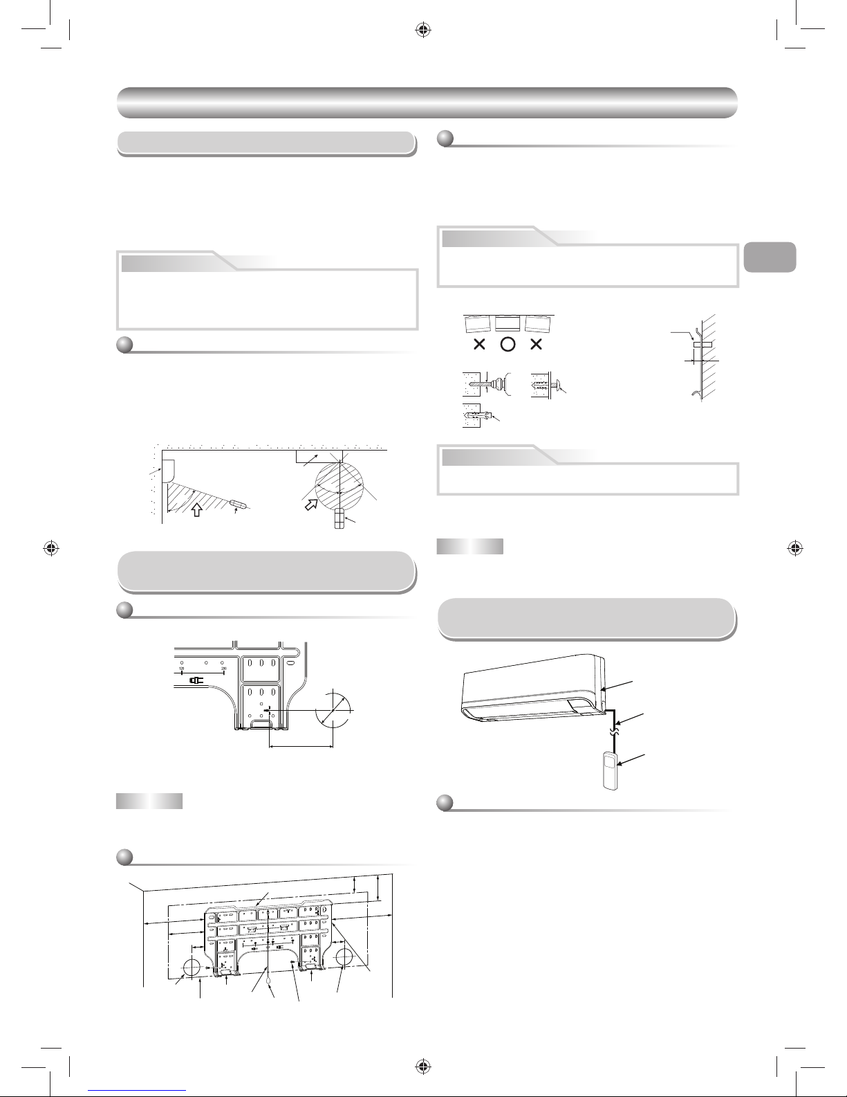
7
ES
6
Placa de instalación
(Mantenga la posición horizontal.)
Orifi cio, 5 mm diá
Gancho de anclaje
(partes locales)
Tornillo de montaje
Ø4 x 25R
Perno de anclaje
Proyección
15 mm o menos
UNIDAD INTERIOR
UNIDAD INTERIOR
Lugar de Instalación
Control remoto
• Un lugar en el que no haya obstáculos tal como una cortina que pudiese
bloquear las señales del unidad interior
• No instale el control remoto en un lugar expuesto a la luz directa del sol o
ceraca de una fuente de calor, por ejemplo una estufa.
• Mantenga el control remoto por lo menos a 1 m de distancia de su equipo
de TV o estéreo. (Esto es necesario para evitar interrupciones o ruidos de
interferencia.)
•
La ubicación del control remoto deberá determinarse tal como se ilustra abajo.
Corte de un Orifi cio y Montaje
de la Placa de Instalación
NOTA
• Cuando la perforación de una pared que contenga listones, listones de
alambre o placas de metal, asegúrese de utilizar un anillo de borde como
molde del orifi cio de la tubería vendido por separado.
Corte de un orifi cio
Cuando instale las tuberías refrigerantes desde la parte posterior
Montaje de la placa de instalación
Cuando la placa de instalación es directamente
montada sobre la pared
1. Fije fi rmemente la placa de instalación sobre la pared atornillando las partes
superior e inferior para enganchar la unidad interior.
2. Para montar la placa de instalación sobre una pared de hormigón con tacos,
utilice los orifi cios para tacos tal como se muestra en la fi gura de abajo.
3. Instale la placa de instalación horizontalmente en la pared.
Cuando instale la placa de instalación con un tornillo de montaje no utilice
el orifi cio del cerrojo de áncora. Si no, la unidad se podría caer y resultar
en daños personales y en daños de propiedad.
1.
Después de determinar la posición del orifi cio de la tubería con la placa de
montaje
(Æ),
perfore el orifi cio de la tubería (Ø65 mm) ligeramente inclinado
hacia abajo al lado exterior.
• Un lugar que brinde espacio alrededor de la unidad interior tal como se
muestra en el diagrama
• Un lugar en el que no haya obstáculos cerca de la entrada y salida de aire
•
Un lugar que permita una instalación fácil de la tubería para la unidad exterior
• Un lugar que permita que el panel delantero se abra
• La unidad interior debe instalarse al menos a 2,5 m de altura. También, se
debe evitar poner cualquier cosa encima de la unidad interior.
PRECAUCIÓN
54 °
4
5°
5
7
°
(Vista lateral) (Vista superior)
Unidad interior
Margen de recepción
Control remoto
Control
remoto
Margen de
recepción
Unidad interior
PRECAUCIÓN
• En caso de paredes de bloques, ladrillos, hormigón o de tipo similar, haga
orifi cios un diámetro de 5 mm en la pared.
• Inserte tacos para tornillos de montaje 6 apropiados.
NOTA
• Fije las cuatro esquinas y partes inferiores de la placa de instalación con 4
u 6 tornillos de montaje.
PRECAUCIÓN
• Se deberá evitar la luz directa del sol sobre el receptor de control a distancia de la unidad interior.
• El microprocesador de la unidad interior no deberá estar tan cerca de las
fuentes de ruido RF.
(Para los detalles, vea el manual del usuario.)
Si no instala fi rmemente la unidad podría causar daños personales o
materiales.
El orifi cio del centro de la
tubería está sobre la lecha.
Orifi cio de
la tubería
Ø65 mm
120 mm
144
50
50
300
65
103
300
Gancho
Gancho
Gancho
Orifi cio de
la tubería
Orifi cio de la tubería
Placa de
instalación
Tornillo de montaje
Peso
Unidad interiora
Hebra
6
1
1 Abra dos tapas de rosca y quite de forma segura dos tornillos del panel
frontal.
2. Abra parcialmente la parte inferior del panel frontal y tire de la parte
superior hacia usted para sacarlo de la placa posterior como se muestra
en la fi gura 1.
3. Coloque el cable de control según sus detalles y especifi caciones como
se muestra en la fi gura 2.
4. Conecte de forma segura el cable de control al terminal del panel de
la unidad de visualización como se muestra en la fi gura 3 (apriete
fi rmemente pero no más de 0,12 N·m (0,01 kgf·m)).
5. Coloque el cable de control por fuera de la unidad interior a igual porción
que la fuente de alimentación y el cable de conexión como se muestra
en la fi gura 3. (Muesca para salida del cable)
6. Vuelva a ensamblar la unidad interior en proceso inverso de 1 a 2.
Unidad interior
Cable de control
Mando a distancia
Cómo conectar el mando a distancia
para la función de cableado
Para la unidad interior
02_1118350131-ES.indd 702_1118350131-ES.indd 7 2/14/2560 BE 2:10 PM2/14/2560 BE 2:10 PM
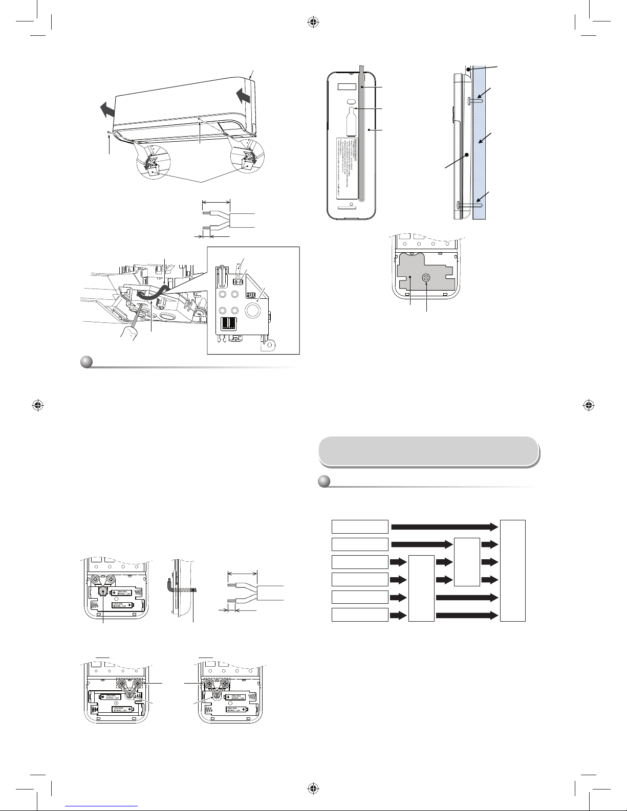
8
* Como la condensación produce problemas en el equipo, asegúrese de
aislar las dos tubarías de conexión. (Utilice espuma de polietileno como
material aislante.)
Formación la tubería y el tubo de desagüe
Posterior derecho
Posterior izquierdo
Inferior izquierdo
Izquierdo
Inferior derecho
Derecho
Troquelado de ranura
de parte trasera
Cambio del tubo
de desagüe
Preparación de la tubería
Instalación la Tubería y el
Tubo de Desagüe
1. Troquelado de ranura de parte trasera
Corte la ranura hacia la izquierda o el lado derecho de la parte trasera
para la conexion izquierda o derecha y la ranura en el lazo inferior
izquierdo o derecho del cuerpo trasero para la conexión inferior izquierda
o derecha con un par de tenazas.
2. Cambio del tubo del desagüe
Para los desagües de las conexiones izquierda, inferior izquierda y
posterior izquierda, es necesario cambiar el tubo y la tapa del desagüe.
1. Quite la tapa del mando a distancia deslizándola hacia abajo y sáquela.
2. Si tiene pilas, sáquelas. La combinación del uso del mando de cable y
las pilas puede provocar la explosión de las pilas.
3. Haga un agujero para introducir el cable de control rompiendo la lámina
de poliéster con un destornillador como se muestra en la fi gura 4.
4. Introduzca el cable de control por la parte posterior del mando a
distancia como se muestra en la fi gura 5.
5. Fije el cable de control tal como se muestra en las fi guras 6 y 7 al
terminal con los tornillos proporcionados (apriete fi rmemente pero no
más de 0,25 N·m (0,03 kgf·m)).
6. Coloque el cable de control por la canaleta de la parte posterior del
mando a distancia como se muestra en la fi gura 8.
7. Fije el tornillo proporcionado (Ø3,1×16L) a la pared para colgar el
mando a distancia como se muestra en la fi gura 9.
8. Marque y alinee el agujero para fi jar el tornillo de abajo (Ø3,1×25L)
como se muestra en la fi gura 9.
9. Ensamble la tapa de la pila proporcionada en la bolsa de accesorios y
use el tornillo proporcionado (Ø3,1×25L) para fi jarla a la pared como se
muestra en la fi gura ! (apriete fi rmemente pero no más de 0,15 N·m
(0,02 kgf·m)).
10. Vuelva a ensamblar la tapa del mando a distancia.
Para el mando a distancia
*Comentario : 1. Se recomienda el uso de un cable de alimentación con
doble aislamiento para conectar el mando a distancia y
el aire acondicionado.
2. Para la función de cableado, 1 mando a distancia solo
puede controlar 1 unidad interior.
3. En la función de cableado, el mando a distancia
regresará a su condición inicial (PRESET
(PROGRAMACIÓN), TIMER (TEMPORIZADOR) y
CLOCK (RELOJ) regresarán a su condición inicial)
cuando el usuario apague el aire acondicionado.
2
3
* Tamaño del cable 28-22 AWG
ó 0,08-0,32 mm
2
Diámetro exterior no mayor que
4,7 mm, longitud del cable de control
de 30 m o menos.
70 mm
5 mm
Terminal
Cable de control
Muesca para salida del cable
Cable de control
Unidad de
visualización
1
Tornillo
Tapa de rosca
Tornillo
Panel frontal
Cable de control
Agujero para colgar el
mando a distancia
Mando a distancia
Cable de control
Tornillo (Ø3,1×16L)
para colgar el
mando a distancia
Pared
Tornillo (Ø3,1×25L)
para fi jar la tapa de
la pila
Mando a distancia
89
!
Tapa de la pila
Tornillo
Apriete fi rmemente pero no más
de 0,15 N·m (0,02 kgf·m)
45
Agujero cerrado con lámina
de poliéster para introducir
el cable de control
Cable de control
6
7
Cable de control
Terminal
* Tamaño del cable 28-22 AWG
ó 0,08-0,32 mm
2
Diámetro exterior no mayor que
4,7 mm, longitud del cable de
control de 30 m o menos.
30 mm
10 mm
* Los terminales para el cableado pueden estar a la derecha (tipo A) o izquierda
(tipo B), dependiendo del controlador embalado en la caja.
Tipo A Tipo B
02_1118350131-ES.indd 802_1118350131-ES.indd 8 2/14/2560 BE 2:10 PM2/14/2560 BE 2:10 PM
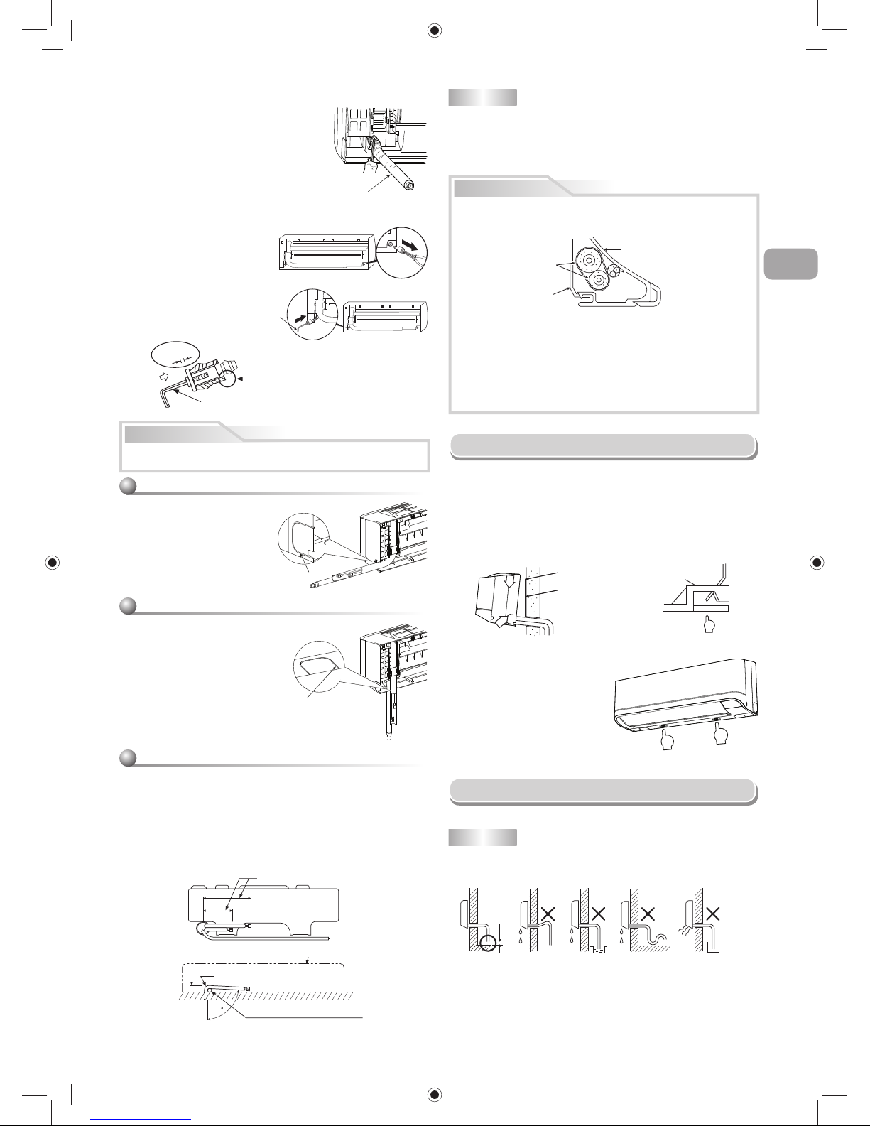
9
ES
4 mm
No utilice aceite lubricante (aceite para
maquinaria refrigerante) al insertar la tapa del
desagüe. Su uso provoca que el enchufe se
deteriore y tenga fugas.
Inserte una llave
hexagonal (4 mm).
Sin
espacio
Cómo quitar la tapa de drenaje
Sujete la tapa de drenaje utilizando
alicantes puntiagudos y sáquela.
Cómo quitar la manguera de drenaje
• La manguera de drenaje se puede retirar quitando
el tornillo que fi ja la manguera de drenaje y a
continuación estirando la manguera de drenaje.
• Cuando retire la manguera de drenaje, tenga
cuidado con cualquier borde afi lado de acero.
Los bordes pueden causar heridas.
• Para instalar la manguera de drenaje, introduzca
la manguera de drenaje con fi rmeza hasta que la
parte de conexión haga contacto con el aislador
térmico, y fíjelo con el tornillo original.
Forma de fi jar el tapón de desagüe
1) Inserte una llave hexagonal (4 mm)
en el centro.
2) Inserte fi rmemente el tapón
de desagüe.
Para evitar pérdidas de agua, inserte con fi rmeza el tubo y la tapa del
desagüe.
Para las tuberías derecho o izquierdo
• Después de trazar ranuras de la
parte trasera con un cuchillo o
una clavija, córtelos con un par de
tenazas o una herramienta similar.
Para las tuberías inferior derecho o inferior
izquierdo
• Después de trazar ranuras de la parte
trasera con un cuchillo o una clavija,
córtelos con un par de tenazas o una
herramienta similar.
Conexión del lado izquierdo de la tubería
• Doble la tubería de conexión de tal manera que quede tendida entre 43 mm
sobre la superfi cie de la pared. Si la tubería de conexión fuese tendida más
allá de los 43 mm sobre la superfi cie de la pared, la unidad interior podría ser
inestable en la pared.
Cuando doble la tubería de conexión, asegúrese de utilizar un torcedor de
resortes para no estrujar la tubería.
Doble la tubería de conexión dentro de un radio de 30 mm.
Conexión de la tubería después de la instalación de la unidad (fi gura)
PRECAUCIÓN
80
260 mm
210 mm
43 mm
Lado líquido
Lado de gas
(Al lado del frente del destello)
Contorno de la unidad interior
R 30 mm (Utilice polisin (núcleo de
polietileno) o similar para tubería fl exible.)
Utilice la manija del destornillador, etc.
NOTA
Si la tubería fuese incorrectamente doblada, la unidad interior podría instalarse
de forma inestable sobre la pared.
Después de pasar la tubería de conexión a través del orifi cio de la tubería,
conecte la tubería de conexión a las tuberías auxiliares y envuelva con cinta
para cubrir alrededor de las mismas.
Manguera de drenaje
Corte
Corte
PRECAUCIÓN
Instalación de la Unidad Interior
• Para desmontar la unidad interior
de la placa de instalación, tire de
la unidad interior dirigida hacia Ud
mientras presiona la parte inferior
por las partes especifi cadas.
1.
Pase la tubería a través del orifi cio de la pared, y enganche la unidad
interior sobre la placa de instalación en los ganchos superiores.
2. Mueva la unidad interior hacia la derecha e izquierda para confi rmar que
esté fi rmemente enganchado en la placa de instalación.
3. Mientras presiona la unidad interior sobre la pared por la parte inferior,
engánchelo hacia arriba en la placa de instalación por la parte inferior. Tire
la unidad interior dirigida hacia Ud por la parte inferior para confi rmar que
esté fi rmemente enganchado sobre la placa de instalación.
•
Encinte las tuberías auxiliares (dos) y el cable de conexión fuertemente.
En caso de tubería por el lado izquierdo y por el lado posterior izquierdo,
encinte solamente las tuberías auxiliares (dos).
Unidad interior
Cable de conexión
Tuberías auxiliares
Placa de instalación
• Cuidadosamente arregle las tuberías de tal manera que ninguna de
ellas sobresalga de la placa posterior de la unidad interior.
•
Conecte cuidadosamente las tuberías auxiliares y las tuberías de conexión
a cada una y corte la cinta aisladora en la tubería de conexión para evitar la
doble cinta en la unión, además, selle la unión con cinta de vinilo, etc.
• Puesto que la condensación resulta en problemas para la máquina,
asegúrese de aislar las dos tuberías de conexión.
(Utilice espuma de polietileno como material aislante.)
• Cuando doble una tubería, hágalo de manera que no la chafe.
No levante la
manuguera de drenaje.
No doble la manguera de
drenaje en forma de ondas.
50 mm
o más
No ponga el extremo
de la manguera de
drenaje en el agua.
No ponga el extremo de
la manguera de drenaje
en la acequía de renaje.
Drenaje
1. Coloque la manguera de drenaje inclinada hacia abajo.
NOTA
• El orifi cio deberá hacerse inclinado levemente hacia abajo al lado exterior.
1
2
1
Gancho aquí
Placa de instalación
Gancho
Pulse
(desenganchar)
Presionar
Presionar
02_1118350131-ES.indd 902_1118350131-ES.indd 9 2/14/2560 BE 2:10 PM2/14/2560 BE 2:10 PM
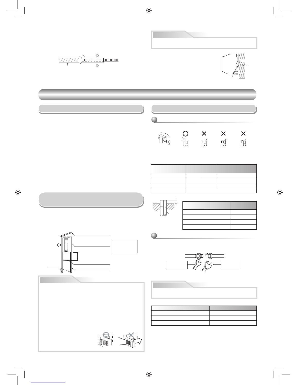
10
Arregle la tubería de drenaje para el drenaje apropiado de la unidad.
El drenaje incorrecto podría causar desperfectos.
Este acondicionador de aire tiene la estructura
designada para drenar el agua colectada de la
condensación, que se forma en la parte posterior
de la unidad, para la bandeja de drenaje. Por
lo tanto, no almacene el cable de alimentación
y otras partes en una altura sobre la guía de
drenaje.
PRECAUCIÓN
UNIDAD EXTERIOR
UNIDAD EXTERIOR
Lugar de Instalación
• Un lugar que tenga espacios alrededor de la unidad exterior tal como se
muestra en el diagrama
• Un lugar que pueda resistir el peso de la unidad exterior y que no permita
el aumento del nivel de ruido y vibración
• Un lugar en donde el ruido de funcionamiento y el aire descargado no
moleste a sus vecinos
• Un lugar que no sea expuesto al viento fuerte
• Un lugar libre de fi ltración de gases combustibles
• Un lugar que no bloquee un pasaje
• Cuando la unidad exterior tenga que instalarse en una posición elevada,
cerciórese de asegurar las patas.
•
Una longitud tolerable de la tubería de conexión es de hasta 20 m.
-
No será necesario añadir refrigerante siempre y cuando la longitud de la
tubería de conexión sea de 15 m o menos.
-
Necesitará añadir 20 g de refrigerante por cada metro añadido a la tubería
de conexión para instalaciones en las que sea necesario que la tubería de
conexión sea de 16 a 20 m.
• La altura permitida para el lugar de instalación de la unidad exterior es de
hasta 12 m.
• Un lugar en donde el agua drenada no de lugar a ningún problemas
Viento
fuerte
PRECAUCIÓN
1. Instale la unidad exterior sin que nada bloquee la descarga del aire.
2. Cuando la unidad exterior es instalada en un lugar expuesto siempre
al viento fuerte como una costa o en la parte superior de un edifi cio,
asegure el funcionamiento normal del ventilador utilizando un conducto
o una protección para el viento.
3. Especialmente en una zona de mucho viento, instale la unidad de
forma que se evite la admisión del viento.
4. La instalación en los siguientes emplazamientos puede resultar
problemática.
No instale la unidad en los siguientes emplazamientos.
• Un lugar expuesto a aceite de máquinas
• Un lugar salino, como la costa
• Un emplazamiento expuesto a gas de sulfuro
• Un lugar donde se puedan generar
con facilidad ondas de alta
frecuencia, como por ejemplo,
las producidas por un equipo de
audio, soldadores y equipos médicos
Protección de la tubería
Manguera de drenaje
de extensión
Dentro de la
habitación
Manguera de drenaje
2. Ponga agua en el depósito de drenaje y asegúrese que el agua se drene
hacia afuera.
3. Cuando conecte la manguera de drenaje de extensión, aisle la parte de la
conexión de la manguera de drenaje de extensión con la protección de la
tubería.
• No utilice la boquilla de drenaje proporcionado para drenar agua. Drene el
agua de los agujeros de drenaje directamente.
• Para proteger la unidad exterior de acumulación de nieve, instale un marco
colgante, y coloque una placa y una tapa de protección contra nieve.
* No utilice ningún diseño amontonado.
Precauciones sobre Instalación en
Regiones con Nieve y Temperaturas Frías
Placa de protección contra nieve
Tapa de protección contra nieve
Línea de acumulación de nieve
Marco colgante
Un mínimo de
50 cm
Realice la instalación
a por lo menos 50 cm
encima de la línea de
acumulación de nieve.
Pernos de
anclaje
Parte frontal
Mitad de la unión
Tuerca
Lado roscado
externamente
Lado roscado
internamente
Utilice una Ilave inglesa
para asegurar.
Utilice una Ilave dinamométrica
para apretar.
(Unidad : N·m)
Diámetro externo de tubería de cobre Tensamiento de torsión a par
Ø6,35 mm 16 a 18 (1,6 a 1,8 kgf·m)
Ø9,52 mm 30 a 42 (3,0 a 4,2 kgf·m)
Ø12,70 mm 50 a 62 (5,0 a 6,2 kgf·m)
A
Tubería
Pinza
90
Oblicuidad Aspereza Deformación
PRECAUCIÓN
Conexión de la Tubería Refrigerante
1. Corte la tubería con un cortatubos para tubería.
2. Inserte una tuerca y abocine la tubería.
• Margen de proyección de ensanchamiento : A (Unidad : mm)
RIDGID (tipo embrague)
Alinee la tubería de conexión y apriete a fondo la tuerca con sus dedos. Luego
apriete la tuerca con una Ilave de tuercas y una Ilave inglesa de torsión tal
como se muestra en la fi gura.
Apriete de la tubería
No aplique demasiada torsión. De otra manera, la tuerca podría quebrarse
según las condiciones de instalación.
Abocinado
Diámetro externo
de tubería de cobre
Herramienta
R32 utilizada
Herramienta
convencional utilizada
Ø6,35 0 a 0,5 1,0 a 1,5
Ø9,52 0 a 0,5 1,0 a 1,5
Ø12,70 0 a 0,5 1,0 a 1,5
Espesor de tubos 0,8 mm o más
IMPERIAL (tuerca de tipo mariposa)
Diámetro externo de tubería
de cobre
R32
Ø6,35 1,5 a 2,0
Ø9,52 1,5 a 2,0
Ø12,70 2,0 a 2,5
Espesor de tubos 0,8 mm o más
Guía de
drenaje
Espacio para
las tuberías
Pared
02_1118350131-ES.indd 1002_1118350131-ES.indd 10 2/14/2560 BE 2:10 PM2/14/2560 BE 2:10 PM
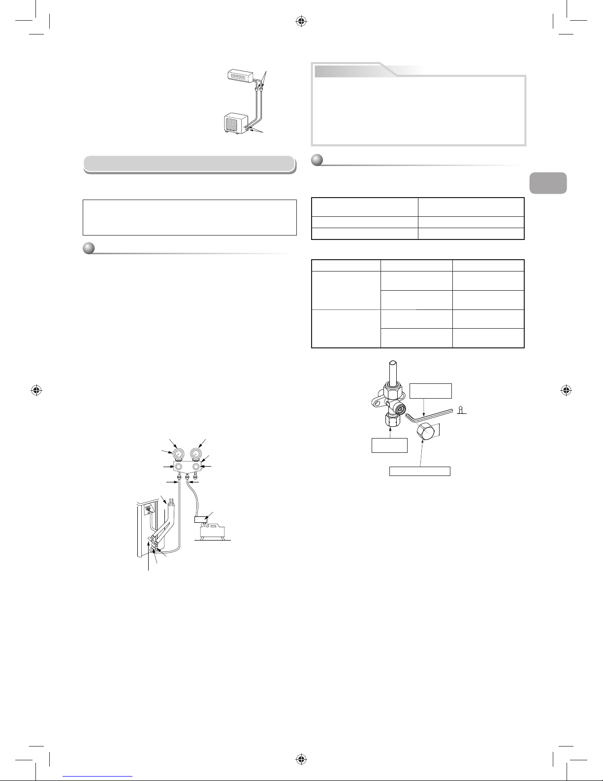
11
ES
Evacuación
Una vez que la tubería se ha conectado a la unidad interior, puede realizar
una purga de aire.
PURGA DE AIRE
Evacue el aire de la tuberías de conexión y en la unidad interior utilizando
la bomba al vacío. No utilice el refrigerante en la unidad exterior. Para los
detalles, vea el manual de la bomba al vacío.
Cerciórese de utilizar una bomba de vacío con función de prevención de
contracorriente para que el aceite interno de la bomba no retroceda a las
tuberías del sistema aire acondicionado cuando la bomba se detenga.
(Si se introduce aceite interno de la bomba de vacío en el sistema de aire
acondicionado que utiliza R32, puede producirse una avería en el ciclo de
refrigeración.)
1. Conecte el manguito de carga de la válvula distribuidora al orifi cio de salida
de la válvula de servicio del lado de gas.
2. Conecte el manguito de carga al orifi cio de la bomba al vacío.
3. Abra completamente el mando lateral de baja presión de la válvula
distribuidora del manómetro.
4. Accione la bomba de vacío para iniciar la evacuación. Realice la evacuación
durante 15 minutos si la longitud de la tubería es de 20 metros. (15 minutos
para 20 metros) (sobre la base de que la bomba tenga una capacidad de
27 litros por minuto) A continuación, confi rme que la lectura compuesta del
manómetro sea de –101 kPa (–76 cmHg).
5. Cierre el mando de la válvula lateral de baja presión del distribución del
manómetro.
6. Abra completamente el vástago de válvula de las válvulas de servicio de
gas y líquido.
7. Retire el manguito de carga del orifi cio de salida.
8. Cierre fi rmemente las tapas de las válvulas de servicio.
Uso de la bomba al vacío
Abocardado
en la unidad
interior
Abocardado
en la unidad
exterior
• Par de apriete de conexiones de tubería
La presión de R32 supera a la de R22
(aprox. 1,6 veces). Por ello, conuna llave de
ajuste dinamométrica, apriete fi rmemente
las secciones de conexión de la tubería de
ensanchamiento que conectan las unidades
interior y exterior según el par de apriete
especifi cado. Las conexiones incorrectas
pueden causar no sólo pérdida de gas, sino
una avería en el ciclo de refrigeración.
Válvula de servicio del lado líquido
Orifi cio de salida (Clavija de válvula (Escena clavija))
Válvula de servicio del lado de gas
Bomba al
vacío
Adaptador de la bomba
al vacío para prevención
de contracorriente
Manguito de carga
Manija del lado de presión alta
(Guarde Ileno Cerrado)
Válvula distribuidora
Manómetro de presión
Manómetro de presión compuesto
Manija del lado
de presión baja
Manguito de carga
Tubería de conexión
–101 kPa
(–76 cmHg)
PRECAUCIÓN
• TENGA EN CUENTA LOS 5 PUNTOS ESENCIALES DE LA
INSTALACIÓN TUBERÍAS.
(1)
Limpie el polvo y humedad (del interior de las tuberías de conexión).
(2) Conexión tensa (entre las tuberías y la unidad).
(3)
Evacue el aire de las tuberías de conexión utilizando la BOMBA DE
VACÍO.
(4) Revise si hay fugas de gas (puntos conectados).
(5) Asegúrese de abrir totalmente las válvulas compactas antes del uso.
Precauciones de manipulación de la válvulas
empaquetada
• Abra completamente la boquilla de válvula, pero no trate de abrirla hasta
el bloqueo.
• Apriete seguro de la tapa de válvula con la torsión de la siguiente tabla:
Tamaño de tubo de la válvula
empaquetada
Tamaño de la llave hexágona
12,70 mm y más pequeña A = 4 mm
15,88 mm A = 5 mm
Tapa Tamaño de tapa (H) Torsión
Tapa de barra de
válvula
H17 - H19
14~18 N·m
(1,4 a 1,8 kgf·m)
H22 - H30
33~42 N·m
(3,3 a 4,2 kgf·m)
Tapa de toma de
servicio
H14
8~12 N·m
(0,8 a 1,2 kgf·m)
H17
14~18 N·m
(1,4 a 1,8 kgf·m)
A
H
Se requiere una
llave hexágona.
Tapa de toma
de servicio
Tapa de barra de válvula
02_1118350131-ES.indd 1102_1118350131-ES.indd 11 2/14/2560 BE 2:10 PM2/14/2560 BE 2:10 PM
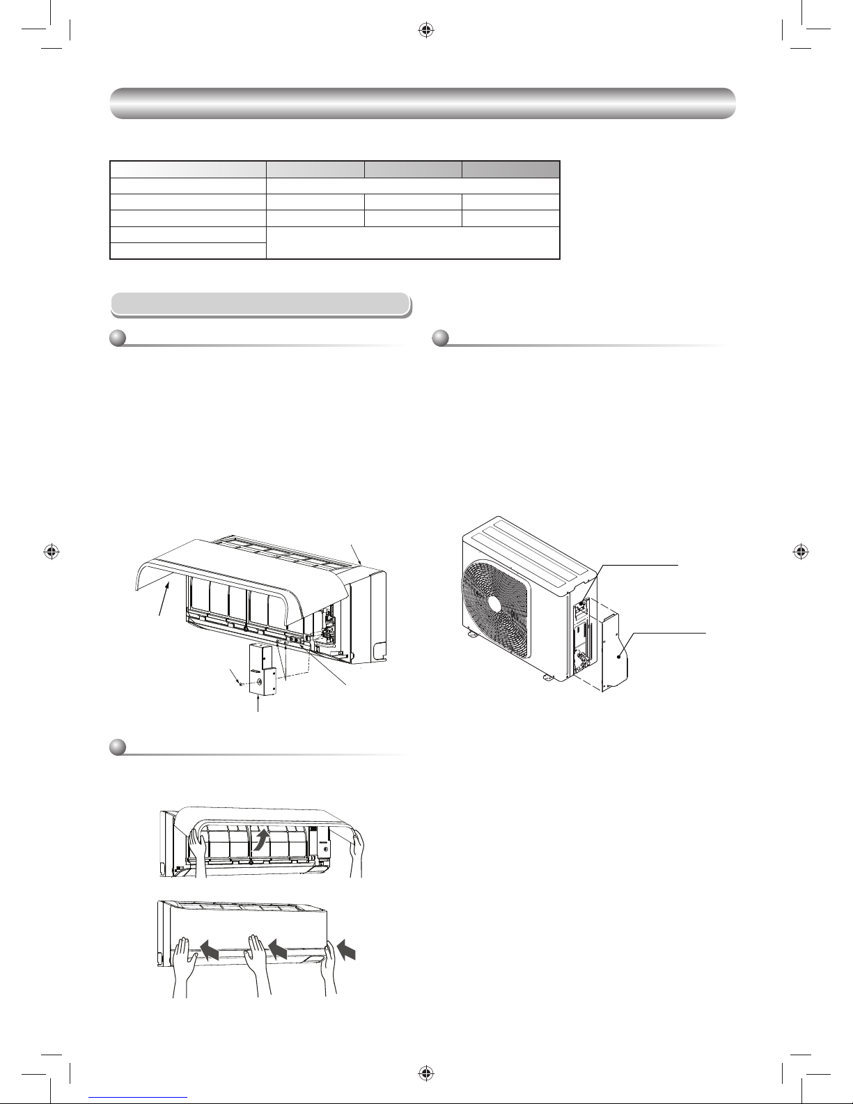
12
TRABAJOS ELÉCTRICOS
TRABAJOS ELÉCTRICOS
La fuente de alimentación puede seleccionarse para conectarse a la unidad interior o a la exterior. Elija el modo correcto y conecte la fuente de alimentación
y el cable de conexión siguiendo las siguientes instrucciones.
Conexión de Cables
Unidad interior Unidad exterior
Cubierta de válvula
Bloque de terminales
Procedimiento para instalar la rejilla de entrada
de aire en la unidad interior
• Para instalar la rejilla de entrada de aire ha de realizarse el procedimiento
inverso a su extracción.
El cableado del cable de conexión puede realizarse sin quitar el panel
frontal.
1. Extraiga la rejilla de entrada de aire.
Tire de la rejilla de entrada de aire hacia fuera para abrirla.
2. Quite la tapa de los terminales y el cable con abrazadera.
3. Inserte el cable de conexión (según los códigos locales) en el orifi cio de la
tubería de la pared.
4. Saque el cable de conexión a través de la ranura del cable del panel
posterior hasta que sobresalga aproximadamente 20 cm.
5. Inserte el cable de conexión completamente en el bloque de terminales y
asegúrelo fuertemente con un tornillo.
6. Tensamiento de torsión a par : 1,2 N·m (0,12 kgf·m)
7. Asegure el cable de conexión con el cable con abrazadera.
8. Fije la cubierta del terminal, el cojinete de la placa trasera y la rejilla de
entrada de aire de la unidad interior.
Cable con abrazadera
Cubierta del terminal
Tornillo
Tornillo
Rejilla de entrada
de aire
Panel frontal
1. Retire la cubierta de la válvula, la cubierta de las partes eléctricas y el
cable con abrazadera de la unidad exterior.
2. Conecte el cable de conexión al terminal como está identifi cado en los
números que coincidan en el bloque de terminales de las unidades
interior y exterior.
3. Introduzca el cable de alimentación y el cable de conexión
cuidadosamente en el bloque de terminales y asegúrelo fuertemente con
tornillos.
4. Utilice cinta de vinilo, etc. para aislar los cables que no se van a utilizar.
Localízelos de modo que no toque ninguna parte eléctrica o de metal.
5. Asegure el cable de alimentación y el cable de conexión con el cable con
abrazadera.
6. Una la cubierta de las partes eléctricas y la cubierta de la vávula en la
unidad exterior.
Modelo RAS-10PKVSG-E RAS-13PKVSG-E RAS-16PKVSG-E
Fuente de alimentación 50Hz, 220 – 240 V Monofásico
Corriente máxima 6,75A 7,35A 8,95A
Valor nominal del disyuntor 8,5A 9,5A 11,5A
Cable de fuente de alimentación
H07RN-F o 60245 IEC66 (1,5 mm2 o más)
Cable de conexión
02_1118350131-ES.indd 1202_1118350131-ES.indd 12 2/14/2560 BE 2:10 PM2/14/2560 BE 2:10 PM

13
ES
Entrada de la fuente de alimentación en el bloque de terminales de la unidad interior (recomendado)
Unidad interior Unidad exterior
Cable de suministro de corriente
conecta a L N
Bloque de terminales
(L N 1 2 3)
Línea de tierra
Cable de
fuente de
alimentación
Cable de fuente de
alimentación
Pelado del cable de
alimentación
N
L
Línea de tierra
50 mm
10 mm
70 mm
10 mm
Cable de conexión
Línea de
tierra
Cable de
conexión
Bloque de terminales
Cable de conexión
conecta a
1 2 3
Bloque de terminales (L N 1 2 3)
Línea de
tierra
Cable de
fuente de
alimentación
Cable de
conexión
Línea de tierra
Cable de conexión
Pelado del cable de conexión
3
50 mm
Línea de tierra
10 mm
70 mm
10 mm
Entrada de la fuente de alimentación en el bloque de terminales de la unidad exterior (opcional)
Unidad interior Unidad exterior
Cable de conexión
conecta a
L 2 3
Bloque de terminales (L N 1 2 3)
Línea de tierra
Cable de conexión
Cable de conexión
Pelado del cable de conexión
3
2
L
Línea de tierra
50 mm
10 mm
70 mm
10 mm
Cable de conexión
Línea de tierra
Línea de tierra
Cable de conexión
Cable de alimentación
Bloque de
terminales
Cable de alimentación
Conexión de la Fuente de Alimentación y el Cable de Conexión
02_1118350131-ES.indd 1302_1118350131-ES.indd 13 2/14/2560 BE 2:10 PM2/14/2560 BE 2:10 PM

14
PRECAUCIÓN
1. La fuente de alimentación debe tener el valor nominal del acondicionador de aire.
2. Prepare la fuente de alimentación para el uso exclusivo con el acondicionador de aire.
3. Debe utilizarse el disyuntor para la línea de la fuente de alimentación de este acondicionador de aire.
4. Asegúrese de que la fuente de alimentación y el cable de conexión se ajustan con el tamaño y el método de cableado.
5. Todos los cables deben conectarse con fi rmeza.
6. Haga el trabajo de cableado de modo que deje una capacidad generosa de cableado.
7. Las conexiones de cableado incorrecto podrían causar que se quemen algunas de las piezas eléctricas.
8. Si se lleva a cabo un cableado incorrecto o incompleto, puede calcinarse o humear.
9. Este producto puede conectarse a la fuente de alimentación principal.
Conexión al cableado fi jo: El cableado fi jo debe tener incorporado un interruptor que desconecte todos los polos y tenga una separación de contacto
de al menos 3 mm.
Entrada de la fuente de alimentación en el bloque de terminales de la unidad interior (recomendado)
Bloque de
terminales
interior
Entrada de
la fuente de
alimentación
Bloque de
terminales
exterior
UNIDAD INTERIOR
UNIDAD EXTERIOR
CHASIS
CHASIS
TIERRA
Entrada de la fuente de alimentación en el bloque de terminales de la unidad exterior (opcional)
Bloque de
terminales
interior
Entrada de
la fuente de
alimentación
Bloque de
terminales
exterior
UNIDAD INTERIOR
UNIDAD EXTERIOR
CHASIS
CHASIS
TIERRA
Entrada de la Fuente de Alimentación en el Diagrama de Cableado
02_1118350131-ES.indd 1402_1118350131-ES.indd 14 2/14/2560 BE 2:10 PM2/14/2560 BE 2:10 PM

15
ES
OTROS
OTROS
Comprobación de Fugas Prueba de Operación
Ajuste de Reinicio Automático
El producto fue embarcado con la función de reinicio automático en la
posición de desactivado. Actívelo según se requiera.
Como ajustar el reinicio automático
Mando a distancia A-B Selección
Para separar la utilización del mando a distancia para cada unidad interior en
caso de que 2 aires acondicionados estén instalados cerca.
Confi guración de mando a distancia B.
1. Pulse el botón [RESET] en la unidad interior para ENCENDER el aire
acondicionado.
2. Apunte el mando a distancia en dirección a la unidad interior.
3. Mantenga pulsado el botón [CHECK] en el mando a distancia con la
punta del lápiz. Aparecerá “00” en la pantalla (Figura 1).
4. Pulse [MODE] mientras pulsa [CHECK]. Aparecerá “B” en la pantalla y
“00” desaparecerá y se APAGARÁ el aire acondicionado. Se memorizará
el mando a distancia B (Figura 2).
Nota : 1. Repita el paso anterior para reiniciar el mando a distancia A.
2. El mando a distancia A no tiene pantalla “A” .
3. La Confi guración de fábrica del mando a distancia es A.
• Compruebe los escapes de gas con un detector de escapes o agua
enjabonada en las conexiones con tuercas.
Este producto está diseñado para que después de un fallo de alimentación, se
pueda reiniciar automáticamente al mismo modo operación tal como estaba
antes del fallo eléctrico.
Información
Para conectar el modo de TEST RUN (COOL), presione y mantenga
presionado el botón [RESET] durante aproximadamente 10 segundos.
(La máquina emitirá un bip corto.)
• Cuando se instalan dos unidades interiores en la misma habitación o en
dos habitaciones adyacentes, al conectar una de ellas, puede que las
dos unidades reciban simultáneamente la señal del mando a distancia y
empiecen a funcionar. En este caso, la operación se puede mantener si
se confi gura la opción B desde cualquier control remoto (Ambas vienen
confi guradas de fábrica en la posición A).
• La señal del mando a distancia no se recibe cuando la confi guración de la
unidad interior y la del mando a distancia son diferentes.
• No existe relación alguna entre confi guración A/confi guración B y
habitación A/habitación B al conectar la conducción y los cables.
1. Mantenga pulsado el botón [RESET] de la unidad interior durante
3 segundos para realizar la operación (3 pitidos y la luz de OPERATION
parpadea 5 veces por segundo durante 5 segundos).
2. Mantenga pulsado el botón [RESET] de la unidad interior durante
3 segundos para cancelar la operación (3 pitidos, pero la luz de
OPERATION no parpadeará).
• En caso de que se active o desactive el temporizador, no se activará
la FUNCIÓN DE REINICIO AUTOMÁTICO.
Compruebe los
lugares para la
unidad interior.
Compruebe los
lugares para la
unidad exterior.
Botón OPERATION /
RESET
12
02_1118350131-ES.indd 1502_1118350131-ES.indd 15 2/14/2560 BE 2:10 PM2/14/2560 BE 2:10 PM

16
APÉNDICE
APÉNDICE
Instrucciones de instalación
Los tubos existentes para R22 y R410A se pueden
reutilizar en las instalaciones de los productos de R32
con inversor.
ADVERTENCIA
Debe comprobar si los tubos existentes que se van a
reutilizar presentan arañazos y abolladuras, así como
confirmar si la fiabilidad en cuanto a la resistencia
de los tubos se ajusta a las condiciones del lugar de
instalación.
Si se cumplen las condiciones especificadas, es
posible adaptar los tubos de R22 y R410A existentes
para utilizarlos en los modelos con R32.
Condiciones básicas necesarias para
reutilizar los tubos existentes
Compruebe y observe si se dan las tres condiciones
siguientes en los tubos de refrigeración.
1. Sequedad (no hay humedad dentro de los tubos.)
2. Limpieza (no hay polvo dentro de los tubos.)
3. Estanqueidad (no hay fugas de refrigerante.)
Restricciones para el uso de los tubos
existentes
En los casos siguientes, no se deben reutilizar
directamente los tubos existentes. Limpie los
tubos existentes o cámbielos por tubos nuevos.
1. Si los tubos presentan arañazos o abolladuras
considerables, asegúrese de utilizar tubos nuevos
en la instalación de los tubos del refrigerante.
2. Si el grosor del tubo existente es menor que el
especificado en “Diámetro y grosor del tubo”,
asegúrese de utilizar tubos nuevos en la instalación
de los tubos del refrigerante.
y La presión de trabajo del refrigerante R32 es alta
(1,6 veces la de R22). Si el tubo presenta arañazos
o abolladuras, o si se utiliza un tubo más fino de
lo indicado, la resistencia a la presión puede ser
insuficiente, lo cual puede hacer que, en el peor de
los casos, el tubo se rompa.
* Diámetro y grosor del tubo (mm)
Diámetro exterior del tubo Ø6,4 Ø9,5 Ø12,7
Grosor
R32, R410A
0,8 0,8 0,8
R22
3. Si la unidad exterior se dejó con los tubos
desconectados, o hubo una fuga de gas en los
tubos y no fueron reparados ni rellenados.
y Es posible que haya entrado agua de lluvia, aire o
humedad en el tubo.
4. Cuando no es posible recuperar el líquido refrigerante
mediante una unidad de recuperación de refrigerante.
y Cabe la posibilidad de que siga habiendo una gran
cantidad de aceite sucio o humedad en el interior
del tubo.
5. Cuando se ha instalado un secador (disponible en el
mercado) en los tubos existentes.
y Es posible que se haya generado óxido verde de
cobre.
6. Cuando el aparato de aire acondicionado actual se
retira después de haberse recuperado el refrigerante.
Compruebe si ese aceite es claramente distinto del
aceite normal.
y El aceite refrigerante tiene el color del óxido verde
de cobre:
Es posible que se haya mezclado humedad con el
se haya generando óxido dentro del tubo.
y El aceite está decolorado, hay gran cantidad de
residuos o mal olor.
y Se observa gran cantidad de restos brillantes
de polvo metálico u otros residuos en el aceite
refrigerante.
7. Cuando el aparato de aire acondicionado tiene un
historial de averías y sustituciones del compresor.
y Se producirán problemas cuando se observe la
presencia de aceite decolorado, gran cantidad de
residuos, polvo metálico brillante u otros residuos
o mezcla de materias extrañas.
8. Cuando se produzcan repetidas instalaciones
temporales y desmontajes del aparato de aire
acondicionado, por alquiler temporal u otras razones.
9. Si el aceite refrigerante del aparato de aire
acondicionado existente no es uno de los siguientes:
aceite mineral, Suniso, Freol-S, MS (aceite sintético),
alquil benceno
(HAB, congelabarril), serie éster, PVE solo de la serie
éter.
y El aislamiento de bobina del compresor puede
deteriorarse.
NOTA
Los casos descritos anteriormente han sido confirmados
por nuestra empresa y reflejan nuestros puntos de vista
sobre nuestros aparatos de aire acondicionado, por lo
que no se garantiza el uso de tubos existentes con
aparatos de aire acondicionado de otras empresas que
utilicen el refrigerante R32.
Cuidado de los tubos
Cuando vaya a desmontar y abrir la unidad interior o
exterior durante mucho tiempo, cuide los tubos de la
siguiente manera:
y De lo contrario, puede aparecer óxido cuando,
debido a la condensación, se produzca la entrada de
humedad o materias extrañas en los tubos.
y No es posible eliminar la oxidación mediante
limpieza. Será necesario sustituir los tubos.
Lugar de
colocación
Plazo Tratamiento
Exterior
1 mes o más Estrangulamiento
Menos de 1 mes
Estrangulamiento
o sellado
Interior Cada vez
¿Presentan arañazos o desperfectos los tubos
existentes?
¿Es posible poner en marcha el aparato de aire
acondicionado existente?
y Tras poner en marcha el aparato de aire acondicionado
existente en el modo de refrigeración durante un
periodo aproximado de 30 minutos,* recupere el
refrigerante.
y Para la limpieza de los tubos y la recuperación del
aceite
y Recuperación de refrigerante: método de bombeo
y Desmonte el aparato de aire acondicionado de los
tubos y realice un drenaje (presión de nitrógeno 0,5
MPa) para eliminar los restos que hubieran podido
quedar en el interior del tubo.
Nota: En el caso de tubos dobles, asegúrese de realizar
también el drenaje del tubo de bifurcación.
Conecte las unidades interior / exterior al tubo existente.
y Use una tuerca abocinada fijada a la unidad
principal para las unidades interior / exterior.
(No utilice la tuerca abocinada del tubo existente.)
y Vuelva a mecanizar el tamaño de mecanizado
abocinado al tamaño adecuado para R32.
y (Prueba de hermeticidad), Secado de vacío, Carga
de refrigerante, Comprobación de fugas de gas
Prueba de funcionamiento
¿Se ha descargado aceite muy descolorido
o una gran cantidad de restos? (Cuando el aceite
se deteriora, su color cambia a un color negro
o marrón.)
Tubos existentes: no pueden utilizarse.
y Use tubos nuevos.
Limpie los tubos o use tubos nuevos.
Tubos necesarios para cambiar la tuerca abocinada /
tamaño del abocinamiento debido a compresión
del tubo
1) Ancho de la tuerca abocinada: H
H
(mm)
Diámetro exterior
del tubo de cobre
Ø6,4 Ø9,5 Ø12,7
Para R32, R410A 17 22 26
Para R22 Igual al anterior 24
2) Tamaño del abocinamiento: A
A
(mm)
Diámetro exterior
del tubo de cobre
Ø6,4 Ø9,5 Ø12,7
Para R32, R410A 9,1 13,2 16,6
Para R22 9,0 13,0 16,2
Ligeramente más grande para R32
No vierta aceite refrigerante sobre la superficie
abocinada.
(Si se produce la descarga de restos, esto indica
que existe una gran cantidad de restos presente.)
SÍ
SÍ
NO
NONOSÍ
Presión del gas nitrógeno 0,5 MPa
02_1118350131-ES.indd 1602_1118350131-ES.indd 16 2/14/2560 BE 2:10 PM2/14/2560 BE 2:10 PM

1
FR
MESURES DE SÉCURITÉ
MESURES DE SÉCURITÉ
• Avant installation, lire attentivement les consignes de sécurité suivantes.
• Respecter impérativement les consignes fournies ici afi n d’éviter toute situation
dangereuse. Les symboles et leur signifi cation sont indiqués ci dessous.
AVERTISSEMENT : Indique qu’un usage incorrect de cette unité peut entraîner
des blessures graves, voire la mort.
ATTENTION : Indique qu’un usage incorrect de cette unité peut entraîner
des blessures corporelles (*1) ou des dommages matériels
(*2).
*1: Par blessure corporelle, comprendre un accident,
une brûlure ou un choc électrique sans gravité et ne
nécessitant pas d’hospitalisation ni traitement hospitalier
à long terme.
*2: Par dommage matériel, comprendre un dommage plus
important affectant des biens ou des ressources.
Pour l’utilisation grand public
Les câbles d’alimentation et de raccordement de l’appareil doivent être au moins
des câbles souples recouverts d’une gaine en polychloroprène (type H07RN-F) ou
des câbles portant la désignation 60245 IEC66. (L’installation doit être conforme à
la réglementation nationale en vigueur pour le câblage.)
Cet appareil doit être raccordé à l’alimentation électrique par l’intermédiaire d’un
disjoncteur ou d’un interrupteur automatique dont les contacts de tous les pôles
doivent être séparés d’au moins 3 mm.
ATTENTION
Pour déconnecter l’appareil de l’alimentation principale
Lisez attentivement les
consignes de ce manuel avant
d’utiliser l’unité.
Cet appareil contient du R32.
03_1118350131-FR.indd 103_1118350131-FR.indd 1 2/14/2560 BE 4:24 PM2/14/2560 BE 4:24 PM

2
AVERTISSEMENT
• Ne jamais modifi er cette unité en deplaçant ne fusse qu’une garde de securité
ou en évitant ne fusse qu’un switch d’enclenchement de securité.
• Ne pas installer dans un endroit qui ne peut supporter le poids de l’appareil.
La chut de l’unité peut provoquer des blessures physiques ou des dommages
matériels.
• Avant de commencer les travaux électriques, fi xer une prise agrée au cordon
d’alimentation.
Assurez-vous aussi que l’appareil est correctement mis à la terre.
• L’appareil doit être installé en accord avec les règlements nationaux
d’installation.
Si vous détectez tout défaut, ne pas installer l’unité. Immédiatement contacter
votre revendeur.
DANGER
• UTILISATION PAR DES PERSONNES QUALIFIES SEULEMENT.
• COUPER L’ALIMENTATION PRINCIPALE ET LE COUPEUR AVANT TOUT
TRAVAUX ELECTRIQUES. S’ASSURER QUE TOUS LES SWITCHES ET
LE COUPEUR SONT ETEINTS. TOUT OUBLI PEUT ETRE LA CAUSE
D’ELECTROCUTION.
• CONNECTER LE CABLE DE CONNEXION CORRECTEMENT. SI LA
CONNEXION EST MAUVAISE, DES PARTIES ELECTRIQUES PEUVENT
ETRE ENDOMMAGEES.
• AVANT INSTALLATION, VERIFIER QUE LE CABLE DE TERRE N’EST PAS
COUPE OU DISCONNECTE.
•
NE PAS INSTALLER A COTE DE GAZ COMBUSTIBLE OU DE VAPEURS DE GAZ.
TOUTE ERREUR PEUT ETRE LA CAUSE D’INCENDIE OU D’EXPLOSION.
• POUR PREVENIR LA SURCHAUFFE DE L’UNITE INTERIEURE ET LE
RISQUE D’INCENDIE, PLACER L’UNITE ASSEZ LOIN (2 M MINIMUM) DES
SOURCES DE CHALEUR TELLES QUE LES RADIATEURS, LES APPAREILS
DE CHAUFFAGE, LES FOURS, LES POELES, ETC.
• QUAND L’APPAREIL EST DEPLACE AFIN D’ETRE INSTALLE A UN
NOUVEL EMPLACEMENT, FAIRE TRES ATTENTION A NE PAS METRE LE
REFRIGERANT SPECIFIE (R32) AVEC TOUT AUTRE CORPS GAZEUX DANS
LE CYCLE DE REFRIGERATION. SI DE L’AIR OU TOUT AUTRE GAZ EST
MELANGE DANS LE REFRIGERANT, LA PRESSION DU GAZ DANS LE CYCLE
DE REFRIGERATION DEVIENT ANORMALEMENT ELEVEE ET CELA PEUT
PROVOQUER L’EXPLOSION DU TUYAU ET BLESSER DES PERSONNES.
• DANS LE CAS OU LE GAZ REFRIGERANT S’ECHAPPE DU TUYAU DURANT
LES TRAVAUX D’INSTALLATION, IMMEDIATEMENT FAIRE ENTRER DE L’AIR
FRAIS DANS LA PIECE. SI LE GAZ REFRIGERANT EST RECHAUFFE PAR
DU FEU OU AUTRE CHOSE, CELA PROVOQUE LA FORMATION DE GAZ
DANGEREUX.
03_1118350131-FR.indd 203_1118350131-FR.indd 2 2/14/2560 BE 4:24 PM2/14/2560 BE 4:24 PM

3
FR
• N’utilisez aucun autre réfrigérant que celui spécifi é pour tout rajout ou
remplacement.
Sinon, une haute pression anormale pourrait être générée dans le circuit de
réfrigération, qui pourrait entraîner une panne ou une explosion du produit ou
même des blessures corporelles.
• Pour accélérer le processus de dégivrage ou procéder au nettoyage, n’utilisez
pas d’autres méthodes que celles préconisées par le fabricant.
• L’appareil doit être stocké dans une pièce sans sources d’allumage à
fonctionnement continu (par ex. fl ammes ouvertes, appareil à gaz en
fonctionnement ou chauffage électrique en fonctionnement).
• Sachez que les réfrigérant doivent être inodores.
• L’appareil étant sous pression, ne le percez pas ou ne le brûlez pas. N’exposez
pas l’appareil à la chaleur, à des fl ammes, des étincelles ou autres sources
d’allumage. Sinon, il pourrait exploser et provoquer des blessures voire un décès.
• Pour le modèle R32, utilisez des tuyaux, un écrou d’évasement et des outils
spécifi és pour le réfrigérant R32. L’utilisation des tuyauteries, de l’écrou
d’évasement et des outils existants (R22) peut générer une haute pression
anormale dans le circuit de réfrigération, qui pourrait entraîner explosion ou des
blessures.
• L’épaisseur des tuyaux de cuivre utilisés avec le R32 doit être supérieure à
0,8 mm. N’utilisez jamais de tuyaux de cuivre plus fi ns que 0,8 mm.
• N’effectuez pas de connexion évasée à l’intérieur d’un bâtiment, d’une habitation
ou d’une pièce lorsque vous connectez l’échangeur thermique de l’unité
intérieure à la tuyauterie d’interconnexion.
La connexion de réfrigérant à l’intérieur d’un bâtiment, d’une habitation ou d’une
pièce doit être réalisée par brasage ou par soudure. La connexion de l’unité
intérieure par la méthode d’évasement ne peut être réalisée qu’à l’extérieur ou
hors d‘un bâtiment, d’une habitation ou d’une pièce. La connexion évasée peut
générer une fuite de gaz et une atmosphère infl ammable.
• Après avoir terminé l’installation ou l’entretien, confi rmez l’absence de fuite de
gaz réfrigérant. Des gaz toxiques pourraient être générés en cas de contact
entre le réfrigérant et le feu.
• L’appareil et la tuyauterie doivent être installés, exploités et stockés dans une
pièce d’une surface au sol de plus de A
min
m2.
Calcul de A
min
m2 : A
min
= (M / (2,5 x 0,22759 x h0))
2
M est la quantité de charge de réfrigérant dans l’appareil en kg. h0 est la hauteur
d’installation de l’appareil en m : 0,6 m pour le modèle au sol/1,8 m pour le
modèle mural/1,0 m pour le modèle de fenêtre/2,2 m pour le modèle plafonnier
(Pour ces unités, la hauteur d’installation conseillée est de 2,5 m.).
• Respectez les réglementations nationales en matière de gaz.
03_1118350131-FR.indd 303_1118350131-FR.indd 3 2/14/2560 BE 4:24 PM2/14/2560 BE 4:24 PM

4
UN RAPPORT DOIT ETRE DEPOSE AUPRES DU FOURNISSEUR
D’ELECTRICITE LOCAL
Veillez absolument à ce que l’installation de cet appareil soit préalablement notifi ée
à votre fournisseur d’électricité. En cas de problèmes avec cet appareil ou si son
installation est refusée par le fournisseur d’électricité, notre service clientèle prendra
les mesures adéquates.
■
Informations importantes concernant le réfrigérant utilisé.
Ce produit contient des gaz à effet de serre fl uorés.
Ne libérez pas ces gaz dans l’atmosphère.
Type de réfrigérant: R32
PRG
(1)
valeur : 675 * (ex. R32 réf. AR4)
(1)
PRG = potentiel de réchauffement global
La quantité de réfrigérant est indiquée sur la plaque signalétique de l’unité.
* Cette valeur est basée sur la règlementation sur les gaz F 517/2014
ATTENTION
• L’exposition de l’appareil à l’eau ou à l’humidité avant l’installation peut
provoquer l’électrocution.
Ne pas garder dans un sous-sol humide ou exposer à la pluie ou l’eau.
• Après avoir enlevé l’unité de son emballage, l’examiner soigneusement afi n de
détecter tout défaut.
• N’installez pas l’unité dans un emplacement où une fuite de gaz infl ammable
pourrait se produire. Une fuite et une accumulation de gaz dans l’environnement
de l’unité pourrait occasionner un incendie.
• Ne pas installer dans un endroit qui peut amplifi er les vibrations de l’unité. Ne
pas installer l’appareil dans un endroit susceptible d’amplifi er son niveau sonore
ou dans un endroit où le bruit de l’appareil et de l’air qu’il dégage risque de
déranger les voisins.
• Pour éviter toute blessure physique, manipuler avec précaution les parties aigues.
• SVP lire attentivement le manuel d’installation avant d’installer l’unité. ll contient
des instructions complémentaires importantes pour une installation correcte.
• Le fabricant ne peut être tenu responsable pour tout dommage causé par le non
respect des instructions et descriptions de ce manuel.
03_1118350131-FR.indd 403_1118350131-FR.indd 4 2/14/2560 BE 4:24 PM2/14/2560 BE 4:24 PM

5
FR
PIÈCES ACCESSOIRES
PIÈCES ACCESSOIRES
Unité Intérieure
N° Nom des pièces N° Nom des pièces
1
Plaque d’installation × 1
2
Télécommande sans fil × 1
3
Pile × 2
4
Support de la télécommande × 1
5
Nouveau fi ltre IAQ de Toshiba × 1
6
Vis de montage × 6
7
Vis à bois à tête plate × 2
8
Mode d’emploi × 1
9
Manuel d’installation × 1
!
Vis à bois à tête plate × 1
"
Couvercle des batteries
Unité Extérieure
N° Nom des pièces N° Nom des pièces
#
Mamelon du drain × 1
$
Bouchon étanche × 2
Filtres à air
Nettoyez-les toutes les 2 semaines.
1. Ouvrez la grille d’entrée d’air.
2. Retirez les fi ltres à air.
3. Aspirez ou nettoyez les fi ltres, puis séchez-les.
4. Réinstallez les fi ltres et fermez la grille d’entrée d’air.
Filtre
Entretien et durée de vie
Nettoyer tous les 3 à 6 mois lorsque la poussière s’est accumulée ou recouvre le fi ltre.
1. Il est conseillé d’utiliser un aspirateur pour éliminer les poussières collées ou profondément incrustées dans le fi ltre ou d’utiliser le ventilateur pour
chasser la poussière hors du fi ltre.
2. Si nécessaire, nettoyer le fi ltre à l’eau claire et l’exposer 3 ou 4 heures au soleil ou à l’air libre, jusqu’à ce qu’il soit totalement sec. Sinon, utiliser un
sèchecheveux. Il faut cependant noter que laver le fi ltre à l’eau peut réduire les performances du fi ltre.
3. Remplacer tous les 2 ans ou moins. (Contacter votre revendeur pour acheter un nouveau fi ltre) (P/N : RB-A620DE)
Remarque: La durée de vie du fi ltre dépend du niveau d’impuretés du milieu d’utilisation. Vous devrez probablement nettoyer et remplacer le fi ltre plus
souvent en cas de niveaux élevés d’impuretés. Dans tous les cas, Nous vous recommandons d’utiliser des fi ltres complémentaires qui vous
permettront d’optimiser les effets purifi ants et désodorisants de votre climatiseur.
Filtre
03_1118350131-FR.indd 503_1118350131-FR.indd 5 2/14/2560 BE 4:24 PM2/14/2560 BE 4:24 PM

6
PLAN D’INSTALLATION DES UNITÉS INTÉRIEURE ET EXTÉRIEURE
PLAN D’INSTALLATION DES UNITÉS INTÉRIEURE ET EXTÉRIEURE
Référence
de pièce
Nom des pièces Qté
A
Tuyau du fl uide frigorigène
Côté liquide : Ø6,35 mm
Côté gaz : Ø9,52 mm
(RAS-10, 13PKVSG-E)
: Ø12,70 mm
(RAS-16PKVSG-E)
Un de
chaque
sorte
B
Matériau d’isolation du tuyau
(mousse en polyéthylène, de 6 mm d’épaisseur)
1
C
Mastic, bandes PVC
Un de
chaque
sorte
Pièces d’Installation en Option
• Fixez l’unité extérieure à l’aide des boulons et des écrous de fi xation si
l’appareil doit être exposé à un vent violent.
• Utilisez des boulons d’ancrage et des écrous de Ø8 mm ou de Ø10 mm.
• S’il est nécessaire de purger l’eau de dégivrage, fi xez le mamelon du drain
# et le bouchon étanche $ à la plaque inférieure de l’unité extérieure avant
de l’installer.
Fixation des boulons de l’unité extérieure
2
3
Le tuyau auxiliaire peut être connecté à
gauche, à arrière gauche, à arrière droit,
à droit, à inférieur droit, à inférieur gauche.
Droit
Arrière
droit
Inférieur
droit
Arrière
gauche
Inférieur gauche
Gauche
Isoler les tuyaux séparément et non
ensemble.
Mousse en polyéthylène de 6 mm
d’épaisseur résistante à la chaleur
1
Piles
7
Vis à bois à
tête plate
4
Support de la
télécommande
Ruban adhésif
A appliquer après avoir
effectué un test d’évacuation.
Télécommande sans fi l
Selle de
renforcement
Extension de
l’embout du drain
(Non disponible,
fourni par l’installateur)
Tube protégé
(Fixer au panneau avant.)
Filtre à air
Crochet
Plaque
d’installation
Crochet
65 mm ou plus
300 mm ou plus
300 mm ou plus
600 mm ou plus
100 mm ou plus
100 mm ou plus
600 mm ou plus
600 mm ou plus
Sortie
d’évacuation
Prise d’air
Sortie d’air
108 mm
28 mm
600 mm
320 mm
125 mm
86 mm
102 mm
90 mm
Ø25 mm
Insérez le coussin entre le mur et l’unité
intérieure, et inclinez celle-ci pour qu’elle
fonctionne mieux.
Pour la tuyauterie arrière gauche et droite
Mur
S’assurer que le drain est orienté en
pente vers le bas.
Ne pas laisser l’embout du drain avoir
du mou.
Couper l’ouverture
du tuyau en léger
biais.
La connexion évasée doit être installée à
l’extérieur.
La tuyauterie de
réfrigérant doit être
protégée des dommages
physiques. Installez un
couvercle en plastique
ou équivalent.
La télécommande fournie est sans fi l mais peut
être utilisé avec un câble.
Veuillez consulter la section « Comment connecter
la télécommande pour une fonctionnement par
câble » lorsque la commande par câble est
nécessaire.
5
Filtre
!
Vis à bois à
tête plate
7
Vis à bois à
tête plate
"
Couvercle
des batteries
03_1118350131-FR.indd 603_1118350131-FR.indd 6 2/14/2560 BE 4:24 PM2/14/2560 BE 4:24 PM

7
FR
6
Plaque d’installation
(Maintenez à l’horizontale.)
Orifi ce, dia 5 mm
Clip d’ancrage
(parties locales)
Vis de montage
Ø4 x 25R
Cheville d’ancrage
Projection de
15 mm ou moins
UNITÉ INTÉRIEURE
UNITÉ INTÉRIEURE
Endroit d’Installation
Télécommande
• Endroit tel qu’il n’y a pas d’obstacles comme des rideaux qui pourraient
bloquer le signal de la télécommande
• Ne pas installer la télécommande dans un endroit exposé au soleil ou près
d’une source de chaleur comme un four.
• Garder la télécommande éloignée d’au moins 1 m du plus proche téléviseur
ou équipement stéréo. (Cela est nécessaire pour éviter des distorsion
d’image ou des interférences sonores.)
• L’emplacement de la télécommande devrait être déterminé comme illustré
ci-dessous.
Ouverture du Trou et Montage de
la Plaque d’Installation
NOTE
• Lorsque l’on doit percer un mur contenant une lame de métal, un câble de
métal ou une plaque de métal, utiliser un anneau de bordure d’ouverture du
tube vendu séparément.
Ouverture du trou
Lors de l’installation du tuyau réfrigérant de l’arrière
Montage de la plaque d’installation
Quand la plaque d’installation est directement
montée sur le mur
1. Fixer de façon ferme la plaque d’installation sur le mur en vissant les
parties supérieure et inférieure pour accrocher l’unité intérieure.
2. Pour monter la plaque d’installation sur un mur de béton avec les chevilles
d’ancrage, les utiliser comme représenté ci-dessous.
3. Installer la plaque d’installation horizontalement dans le mur.
Dans le cas de la plaque d’installation avec des vis de montage, ne pas
utiliser les chevilles d’ancrage. L’unité pourrait tomber et provoquer des
blessures corporelles ou des dommages matériels.
1.
Après avoir déterminé l’emplacement du trou du tube sur la plaque de
montage (
Æ), percer l’ouverture du tube (Ø65 mm) légèrement inclinée
vers le bas vers le côté extérieur.
• Endroit qui procure l’espace autour de l’unité intérieure comme représenté
sur le diagramme
• Endroit tel qu’il n’y a pas d’obstacles à l’entrée et sortie d’air
• Endroit qui permet une installation aisée du tuyau de l’unité extérieure
• Endroit qui permet l’ouverture du panneau avant
• Veillez à installer l’unité intérieure à au moins 2,5 m de haut. Veillez
également à ne pas rien placer sur le dessus de l’unité intérieure.
ATTENTION
54 °
4
5°
5
7
°
(Vue de côté) (Vue du dessus)
Unité intérieure
Portée de réception
Télécommande
Télécommande
Portée de
réception
Unité intérieure
ATTENTION
Une mauvaise installation de l’unité peut provoquer des blessures
personnelles et des dommages matériels si l’unité tombe.
• En cas de mur fait de blocks, briques, béton ou matériaux similaires, faire
des trous un diamètre de 5 mm dans le mur.
• Insérer des clips d’ancrage pour les vis de montage 6 correspondantes.
NOTE
• Fixez les quatre coins et les parties inférieures de la plaque d’installation
avec les 4 à 6 vis de montage.
ATTENTION
•
Eviter l’exposition directe au soleil du récepteur sans fi l de l’unité intérieure.
• Le microprocesseur de l’unité intérieure ne doit pas être trop proche de
sources de bruit RF.
(Voir le mode d’emploi pour les détails.)
Le centre du trou du tuyau
est au dessus de la fi èche.
Ouverture
du tube
Ø65 mm
120 mm
144
50
50
300
65
103
300
6
1
Crochet
Crochet
Crochet
Ouverture
du tube
Ouverture du tube
Plaque
d’installation
Vis de montage
Plomb
Unité intérieure
Fil
1 Ouvrir les deux capuchons de vis et retirer soi-gneusement les deux vis
sur le panneau avant.
2. Ouvrir légèrement la partie inférieure du panneau avant puis tirer la partie
supérieure du panneau frontal vers vous pour le retirer comme illustré
sur le schéma 1.
3. Disposez minutieusement le câble de commande comme indiqué dans la
fi gure 2.
4. Raccorder fermement le câble de commande à la borne de l’Affi cheur
comme illustré sur le schéma 3 (serrez fermement mais à un couple ne
dépassant pas 0,12 N·m (0,01 kgf·m)).
5. Disposez le câble de commande à l’extérieur de l’unité interne de
manière à avoir la même proportion en alimentation électrique et en
câble de connexion comme indique dans la fi gure 3. (Encoche pour le
câblage externe)
6. Remontez l’unité interne en effectuant le processus inverse 1 à 2.
Unité intérieure
Câble de commande
Télécommande
Pour l’unité interne
Comment se connecter avec la
télécommande pour un fonctionnement
par câble
03_1118350131-FR.indd 703_1118350131-FR.indd 7 2/14/2560 BE 4:24 PM2/14/2560 BE 4:24 PM

8
* Comme la condensation entraîne des pannes, n’oubliez pas d’isoler les deux
tuyaux de raccordement. (Utiliser de la mousse de polyéthylène comme
matériau isolant.)
Constitution de la conduite et du tuyau de purge
Installation de la Conduite et du
Tuyau de Purge
Arrière droit
Arrière gauche
Inférieur gauche
Gauche
Inférieur droit
Droit
Rainure du corps
arrière découpée à
l’emporte-pièce
Remplacement
du tuyau de
purge
Préparation de la conduite
1. Rainure du corps arrière découpée à l’emporte-pièce
Avec une pince, découpez la rainure sur la gauche ou la droite du corps
arrière pour la connexion à gauche ou à droite, et la rainure du côté
inférieur gauche ou droit du corps arrière pour la connexion inférieure
gauche ou droite.
2. Remplacement du tuyau de purge
Pour la conduite de la connexion gauche, de la connexion inférieure
gauche et de la connexion arrière gauche, vous devez remplacer le
tuyau de purge ainsi que le bouchon de purge.
1. Faîtes glisser le couvercle de la télécommande vers le bas et retirez-le.
2. S’il y a des batteries, retirez-les. L’usage de commande par câble avec
les batteries peuvent entraîner l’explosion de ces dernières.
3. Faites un trou pour insérer le câble de commande en utilisant un
tournevis, déchirez la feuille de polyester comme indiqué dans la fi gure
4.
4. IInsérez le câble de commande à l’arrière de la télécommande comme
indiqué dans la fi gure 5.
5. Fixez le câble de commande à la borne à l’aide des vis fournis (serrez
fermement mais à un couple ne dépassant pas 0,25 N·m (0,03 kgf·m))
et disposez-le comme indiqué dans la fi gure 6 et 7.
6. Disposez le câble de commande le long de la gouttière à l’arrière de la
télécommande comme indiqué dans la fi gure 8.
7. Fixez le vis fourni (Ø3,1×16L) au mur pour suspendre la télécommande
comme indiqué dans la fi gure 9.
8. Marquez et arrangez le trou pour fi xer les vis (Ø3,1×25L) comme
indiqué dans la fi gure 9.
9. Mettez le couvercle des batteries qui est fourni avec un sac
d’accessoires puis utilisez le vis fourni (Ø3,1×25L) pour fi xer le
couvercle des batteries au mur comme indiqué dans le fi gure ! (serrez
fermement mais à un couple ne dépassant pas 0,15 N·m (0,02 kgf·m)).
10. Remettez le couvercle de la télécommande.
Pour l’unité interne
*Remarque : 1. Il est recommandé d’utiliser des isolants pour fi l
d’alimentation pour brancher la télécommande et le
climatiseur.
2. Pour le fonctionnement par able, 1 télécommande peut
contrôler 1 unité interne uniquement.
3. En fonctionnant par câble, la télécommande revient à sa
condition initiale (PREDEFINI, MINUTERIE et HORLOGE
seront réinitialisés) lorsque l’utilisateur coupe l’alimentation
électrique du climatiseur.
2
3
* Taille de câble 28-22 AWG
ou 0,08-0,32 mm
2
Diamètre extérieur 4,7 mm maximum,
câble de commande longueur 30 m ou
moins.
70 mm
5 mm
Borne
Câble de commande
Encoche pour le câblage externe
Câble de commande
Unité
d’affi chage
1
Vis
Capuchon des vis
Vis
Panneau avant
45
Feuille de polyester pour
recouvrir le trou et insérer
le câble de commande.
Câble de commande
6
7
Câble de
commande
Borne
* Taille de câble 28-22 AWG
ou 0,08-0,32 mm
2
Diamètre extérieur 4,7 mm
maximum, câble de commande
longueur 30 m ou moins.
30 mm
10 mm
* Les bornes de câblage peuvent se trouver soit sur la droite (type A) soit sur la
gauche (type B) en fonction de la commande emballée dans le carton.
Type A Type B
Câble de commande
Trou pour suspendre
la télécommande
Télécommande
Câble de
commande
Vis (Ø3,1×16L)
pour suspendre la
télécommande
Mur
Vis (Ø3,1 × 25L) pour
fi xer le couvercle des
batterie
Télécommande
89
!
Couvercle des
batteries
Vis
Serrez fermement mais à un couple ne
dépassant pas 0,15 N·m (0,02 kgf·m)
03_1118350131-FR.indd 803_1118350131-FR.indd 8 2/14/2560 BE 4:24 PM2/14/2560 BE 4:24 PM

9
FR
NOTE
Si le tube est incorrectement courbé, l’unité intérieure peut être instablement
fi xée sur le mur.
Après avoir fait passé le tube de connexion à travers l’ouverture du tube, connecter
le tube de connexion aux tubes auxiliaires et enrouler le ruban de revêtement.
4 mm
N’appliquez pas d’huile lubrifi ante (huile machine
pour réfrigérant) lorsque vous insérez le bouchon
de purge. Cela risque de détériorer le bouchon de
purge et de provoquer des fuites.
Insérez une clé
hexagonale (4 mm).
Aucun
espace
Procédure de dépose du tuyau de purge
• Pour retirer le fl exible d’évacuation, retirer la vis
de fi xation et tirer le fl exible vers l’extérieur.
• Lors du retrait du fl exible d’évacuation, prendre
garde à toutes les bordures tranchantes de la
plaque d’acier. Elles peuvent provoquer des
blessures.
• Pour installer le fl exible d’évacuation, insérer
ce dernier fermement jusqu’à ce que la pièce
de raccordement entre en contact avec l’isolant
thermique et sécuriser le fl exible avec la vis
d’origine.
Procédure de dépose du
bouchon de purge
Saisissez le bouchon au moyen d’une
pince à bec effi lé et extrayez-le.
Procédure de fi xation du
bouchon de purge
1) Insérez une clé hexagonale
(4 mm) dans un manchon.
2) Insérez fermement le bouchon de purge.
Si vous n’insérez pas fermement le tuyau de purge et le bouchon de
purge, de l’eau risque de s’échapper.
Dans le cas d’une conduite à droite ou à gauche
• Après avoir marqué les rainures du
corps arrière avec un couteau ou
une épingle, coupez-lez avec une
pince ou outil similaire.
Dans le cas d’une conduite inférieure droite ou
inférieure gauche
• Après avoir marqué les rainures du
corps arrière avec un couteau ou
une épingle, coupez-lez avec une
pince ou outil similaire.
Connexion à gauche avec le tube
• Tordre le tube de connexion de façon à ce qu’il se trouve à moins de 43 mm
de la surface du mur. Si le tube de connexion se trouve à plus de 43 mm
au-dessus de la surface du mur, l’unité intérieure pourrait être instablement
fi xée sur le mur.
Lors de la torsion du tube de connexion, utiliser une cintreuse à ressort afi n
de ne pas écraser le tube.
Tordre le tube de connexion dans un rayon de 30 mm.
Tube de connexion après installation de l’unité (dessin)
ATTENTION
80
260 mm
210 mm
43 mm
Côté liquide
Côté gaz
(A l’avant de l’évasement/élargissement)
Aspect externe de l’unité intérieure
R 30 mm (Utilisez du polisin
(du polyéthylène) ou un équivalent pour
les tuyaux cintrés.)
Utiliser la poignée du tournevis, etc.
Embout du drain
Incision
Incision
ATTENTION
Installation de l’Unité Intérieure
• Pour enlever l’unité intérieure de
la plaque d’installation, tirer l’unité
intérieure vers soi tout en poussant
son fond vers le haut par les parties
spécifi ées.
1. Passer le tube à travers l’ouverture dans le mur et accrocher l’unité
intérieure sur le crochet supérieur de la plaque d’installation.
2. Pousser l’unité intérieure vers la droite et la gauche afi n de vérifi er si elle
est accrochée fermement sur la plaque d’installation.
3. Tout en poussant la partie inférieure de l’unité intérieure vers le mur,
l’accrocher sur la plaque d’installation par sa partie inférieure. Tirer vers
soi la partie inférieure de l’unité intérieure pour confi rmer qu’elle est
fermement fi xée sur la plaque d’installation.
•
Attacher fermement avec du ruban les tubes auxiliaires (deux) et les câbles
de connexion. Dans le cas d’un tube à gauche et d’un tube à l’arrière à
gauche, seulement attacher les tubes auxiliaires (deux) avec du ruban.
Unité intérieure
Câble de connexion
Tubes auxiliaires
Plaque d’installation
•
Arranger avec précaution les tubes de façon à ce qu’aucun tube ne sorte
de la plaque arrière de l’unité intérieure.
•
Connecter avec précaution les tubes auxiliaires et les tubes de connexion
entre eux et enlever le ruban isolant du tube de connexion pour éviter de
mettre deux fois du ruban sur le joint. De plus, assurer l’étanchéité du joint
avec un ruban en vinyl, etc.
•
Le givre provoquant des problèmes de fonctionnement, s’assurer de bien
isoler les deux tubes de connexion. (Utiliser de la mousse de polyéthylène
comme matériau isolant.)
•
Lors de la courbure d’un tube, ne pas l’écraser.
1
2
1
Accrocher ici.
Plaque d’installation
Crochet
Appuyer
(décrocher)
Pousser
Pousser
Ne pas sur
élever le drain.
Ne pas donner une forme
ondulée au drain.
50 mm
ou plus
Ne pas poser
l’embout du drain
dans l’eau.
Ne pas poser l’embout
du drain dans la rigole
de drainage.
Drainage
1. Orienter le drain en pente vers le bas.
NOTE
• L’ouverture sur le coté extérieur doit être faite en légère pente vers le bas.
03_1118350131-FR.indd 903_1118350131-FR.indd 9 2/14/2560 BE 4:24 PM2/14/2560 BE 4:24 PM

10
Cet appareil d’air conditionné a été désigné
de façon à évacuer dans le bassin l’eau
provenant du givre qui se forme à l’arrière de
l’unité intérieure.
II ne faut donc pas ranger le cordon
d’alimentation ou autre chose à une hauteur
supérieure au guide de drainage.
ATTENTION
UNITÉ EXTÉRIEURE
UNITÉ EXTÉRIEURE
Endroit d’Installation
• Un endroit qui procure de l’espace autour de l’unité extérieure comme
indiqué sur le diagramme
• Un endroit qui peut supporter le poids de l’unité extérieure et n’amplifi e pas
le niveau sonore et les vibrations
• Un endroit tel que les voisins ne sont pas gênés par le bruit et les
évacuations d’air
• Un endroit qui n’est pas exposé à un vent fort
• Un endroit libre de toute fuite de gaz combustible
• Un endroit qui ne bloque aucun passage
• Quand l’unité extérieure doit être installée sur un endroit élevé, s’assurer de
stabiliser son support.
• La longueur du tuyau de raccordement peut atteindre 20 m.
- Il est inutile d’ajouter du fl uide frigorigène si la longueur de la tuyauterie
de raccordement est de 15 m ou moins.
- Vous devrez ajouter 20 g de fl uide frigorigène par mètre de tuyauterie
de raccordement ajoutée si l’installation nécessite une tuyauterie de
16 m à 20 m.
• La hauteur admissible du site d’installation de l’unité extérieure est de 12 m.
• Un endroit tel que l’eau de drainage ne cause aucun problèmes
ATTENTION
1. Installer l’unité extérieure sans que rien ne bloque l’évacuation d’air.
2. Quand l’unité extérieure est installée sur un endroit toujours exposé
à un grand vent comme une côte maritime ou l’étage élevé d’un
immeuble, protéger l’opération normale du ventilateur avec un conduit
ou un bouclier coupe vent.
3. Dans les zones de grand vent, choisir un emplacement d’installation
de façon à ce que le vent ne puisse pas pénétrer dans l’unité.
4. L’installation dans l’un des endroits suivants peut être à l’origine de
problèmes.
Ne pas installer l’appareil dans de tels endroits.
• Un endroit souillé d’huile de machine
• Un endroit salin comme une côte
• Un endroit où l’air est rempli de gaz sulfure
• Un endroit des ondes de haute
fréquence risquent d’être générées
par des équipements audio,
des matériels à souder et des
équipements médicaux
Fixer le tube de drainage de façon à procéder à un drainage correct de l’unité.
Un drainage incorrect peut provoquer des dommages matériels.
Vent
fort
Tube protégé
Extension de l’embout
du drain
Intérieur de la
pièce
Embout du drain
2. Mettre de l’eau dans le bassin de drainage et s’assurer que l’eau est
drainée à l’extérieur.
3. Lors de la connexion de l’extension de l’embout du drain, isoler la partie
de connexion de l’embout du drain du tube protégé.
• Ne pas utiliser le mamelon d’évacuation fourni pour l’évacuation de l’eau.
L’eau doit être évacuée directement depuis les orifi ces d’évacuation.
• Afi n de protéger l’unité extérieure de l’accumulation de neige, installer
une structure de surélévation et fi xer un capot et une plaque de protection
contre la neige.
* Ne pas utiliser pas de conception à double-étage.
Précautions à prendre pour l’installation
dans les régions sujettes aux chutes de
neige et aux températures froides
Plaque de protection contre la neige
Capot de protection contre la neige
Ligne d’accumulation de la neige
Structure de surélévation
Au moins
50 cm
Installer au moins 50 cm
au-dessus de la ligne
d’accumulation de la neige.
Boulons
d’ancrage
Avant
Demi-raccord union
Écrou évasé
Côté fi leté
extérieurement
Côté fi leté
intérieurement
Utiliser une clé pour fi xer. Utiliser une clé dynamométrique pour serrer.
IMPERIAL (type écrou papillon)
Diamètre externe du
tuyau en cuivre
R32
Ø6,35 1,5 à 2,0
Ø9,52 1,5 à 2,0
Ø12,70 2,0 à 2,5
Épaisseur des tuyaux 0,8 mm ou plus
A
Tuyau
Moule
Diamètre externe du
tuyau en cuivre
Outil utilisé pour le
fl uide R32
Outil conventionnel
utilisé
Ø6,35 0 à 0,5 1,0 à 1,5
Ø9,52 0 à 0,5 1,0 à 1,5
Ø12,70 0 à 0,5 1,0 à 1,5
Épaisseur des tuyaux 0,8 mm ou plus
90
Obliquité Rugosité Fibreux
ATTENTION
Connexion du Tuyau Réfrigérant
1. Couper le tuyau à l’aide d’un cutter de tube.
2. Insérer un raccord conique dans le tuyau et évaser le tuyau.
• Marge de projection au cours de l’évasement : A (Unité : mm)
RIDGID (type griffe de serrage)
Aligner les centres des tuyaux de connexion et serrer l’écrou autant que
possible à l’aide des doigts. Ensuite, serrer l’écrou avec une clef à écrou et
une clef dynamométrique comme montré sur le schéma.
Serrage de la connexion
Ne pas provoquer trop de torsion. Autrement, l’écrou pourrait céder en
fonction des conditions d’installation.
Evasement
(Unité : N·m)
Diamètre externe du tuyau en cuivre Torque de serrage
Ø6,35 mm 16 à 18 (1,6 à 1,8 kgf·m)
Ø9,52 mm 30 à 42 (3,0 à 4,2 kgf·m)
Ø12,70 mm 50 à 62 (5,0 à 6,2 kgf·m)
Guide
du drain
Espaces pour
les tubes
Mur
03_1118350131-FR.indd 1003_1118350131-FR.indd 10 2/14/2560 BE 4:24 PM2/14/2560 BE 4:24 PM

11
FR
Evacuation
Après le raccordement de la tuyauterie à l’unité intérieure, vous pouvez
effectuer la purge de l’air en une seule fois.
PURGE DE L’AIR
Evacuer l’air dans les tuyaux de connexion et l’unité intérieure à l’aide de
la pompe d’évacuation. Ne pas utiliser le réfrigérant dans l’unité extérieure.
Pour plus de détails, voir le manuel de la pompe d’évacuation.
Veillez à utiliser une pompe à vide disposant d’une fonction de prévention de
contre courant pour que l’huile interne de la pompe ne refl ue pas dans les
tuyaux du climatiseur lorsque la pompe s’arrête.
(Si l’huile de la pompe à vide pénètre dans le climatiseur utilisant le fl uide
R32, cela risque d’engendrer des troubles du cycle de réfrigeration.)
1. Raccordez le tuyau de chargement de la valve multiple à la port service de
la valve compacte du côté du gaz.
2. Raccordez le tuyau de chargement à la buse de la pompe à vide.
3. Ouvrez complètement la poignée de basse pression de la valve multiple.
4. Actionnez la pompe à vide pour commencer l’évacuation. Effectuez
l’évacuation pendant environ 15 minutes si la longueur du tuyau est de 20
mètres. (15 minutes pour 20 mètres) (en supposant un débit de la pompe
de 27 litres par minute) Puis vérifi ez que l’indication du manovacuomètre
est égale à –101 kPa (–76 cmHg).
5. Fermez la poignée de basse pression de la valve multiple.
6. Ouvrez entièrement la tige de manoeuvre des valves compactes (du côté
du gaz et du côté du liquide).
7. Retirez le tuyau de chargement de la port service.
8. Serrez les capuchons des valves compactes.
Utilisation de la pompe à vide
Evasement du
côté de l’unité
intérieure
Evasement du
côté de l’unité
extérieure
•
Couple de serrage des raccordements de tuyau évasé
La pression du fl uide R32 est supérieure
à celle du fl uide R22 (environ 1,6 fois).
Par conséquent, à l’aide d’une clé
dynamométrique, serrez fermement les
sections de raccordement du tuyau (évasé
reliant les unités intérieure et extérieure)
jusqu’à ce que vous atteigniez le couple
de serrage spécifi é. Des raccordements
incorrects risquent de causer une fuite de
gaz, mais également des troubles du cycle
de réfrigeration.
Valve compacte du côté du liquide
Port service (Cheville de valve (Réglage épingle))
Valve compacte du côté du gaz
Pompe
à vide
Adaptateur de la pompe
à vide pour prévention de
contre courant
Tuyau de chargement
Manette coté haute pression
(Restez plein fermé)
Valve multiple
Jauge de pression
Jauge de pression composée
Manette coté
basse pression
Tuyau de chargement
Tuyau de connexion
–101 kPa
(–76 cmHg)
ATTENTION
• GARDER EN MEMOIRE CINQ POINTS IMPORTANTS EN CE QUI
CONCERNE LA TUYAUTERIE.
(1) Eviter les poussières et l’humidité (dans les tuyaux de connexion).
(2) Bien serrer les connexions (entre les tubes et l’unité).
(3) Evacuer l’air dans les tuyaux de connexion en utilisant la POMPE À
VIDE.
(4) Vérifi er les fuites de gaz (points de connexion).
(5) Verifi ez, avant l’utilisation, que toutes les valves compactes soient
complètement ouverts.
Précautions concernant le maniement des vannes
• Ouvrir entièrement la tige de manoeuvres en la tournant vers l’extérieur
mais n’essayez pas de l’ouvrir au-delà de la butée.
• Serrer fermement le capuchon de la tige de manoeuvre avec le couple
indiqué dans le tableau suivant :
Taille du tuyau de la valve compacte Taille de la clé hexagonale
12,70 mm et de plus petite taille A = 4 mm
15,88 mm A = 5 mm
Capuchon
Taille du capuchon
(H )
Couple
Capuchon de la tige
de manoeuvre
H17 - H19
14~18 N·m
(1,4 à 1,8 kgf·m)
H22 - H30
33~42 N·m
(3,3 à 4,2 kgf·m)
Capuchon du port
d’entretien
H14
8~12 N·m
(0,8 à 1,2 kgf·m)
H17
14~18 N·m
(1,4 à 1,8 kgf·m)
A
H
Clé hexagonale
requise.
Capuchon du
port d’entretien
Capuchon de la
tige de manoeuvre
03_1118350131-FR.indd 1103_1118350131-FR.indd 11 2/14/2560 BE 4:24 PM2/14/2560 BE 4:24 PM

12
TRAVAUX ÉLECTRIQUES
TRAVAUX ÉLECTRIQUES
L’alimentation électrique peut être sélectionnée pour raccorder l’unité intérieure à l’unité extérieure. Choisissez une voie qui convient et raccordez
l’alimentation électrique et le câble de raccordement en suivant les instructions suivantes.
Connexion des Câbles
Unité intérieure Unité extérieure
Couvercle de la valve
Bloc terminal
Comment installer la grille d’entrée d’air sur
l’unité intérieure
• Lorsque vous fi xez la grille d’entrée d’air, vous effectuez l’opération inverse
de celle que vous avez effectuée lorsque vous l’avez retirée.
Le câblage du câble de connexion peut être effectué sans retirer le
panneau avant.
1. Retirez la grille d’entrée d’air.
Ouvrez la grille d’entrée d’air vers le haut et tirez-la vers vous.
2. Retirez le panneau de couverture terminal et l’attache du cordon.
3. Insérez le câble de connexion (en accord avec les règles locales) dans
l’orifi ce pour le tuyau dans le mur.
4. Tirez le câble de connexion à travers l’ouverture pour câble du panneau
arrière afi n qu’il dépasse de 20 cm environ par rapport à l’avant.
5. Entièrement insérez le câble de connexion dans le bloc terminal et le fi xez
fermenent avec des vis.
6. Torque de serrage : 1,2 N·m (0,12 kgf·m)
7. Fixez le câble de connexion avec l’attache du cordon.
8. Fixez le couvre borne, la bague de réduction de la plaque arrière et la grille
d’entrée d’air sur l’unité intérieure.
Attache du cordon
Couvercle des bornes
Vis
Vis
Grille d’entrée
d’air
Panneau avant
1. Retirez le couvercle de la valve, le couvercle des parties électriques et
l’attache du cordon de l’unité extérieure.
2. Connectez le câble de connexion au terminal identifi é par les numéros
correspondants sur le bloc terminal de l’unité intérieure et extérieure.
3. Insérez le cordon d’alimentation et le câble de connexion dans le bloc
terminal et le fi xez-le fermement avec des vis.
4. Utilisez un ruban en vinyle, etc. pour isoler les cordons inutilisés.
Positionnez-les de manière à ce qu’ils ne touchent aucune partie
électrique ou métallique.
5. Fixez le cordon d’alimentation et le câble de connexion avec l’attache du
cordon.
6. Fixez le couvercle des parties électriques et le couvercle de la valve sur
l’unité extérieure.
Modèle RAS-10PKVSG-E RAS-13PKVSG-E RAS-16PKVSG-E
Alimentation électrique 50Hz, 220 – 240 V Monophasé
Intensité d’utilisation maximale 6,75A 7,35A 8,95A
Intensité nominale du disjoncteur 8,5A 9,5A 11,5A
Câble d’alimentation électrique
H07RN-F ou 60245 IEC66 (1,5 mm2 ou plus)
Câble de connexion
03_1118350131-FR.indd 1203_1118350131-FR.indd 12 2/14/2560 BE 4:24 PM2/14/2560 BE 4:24 PM

13
FR
Arrivée de l’alimentation électrique au niveau du bornier de l’unité intérieure (recommandé)
Unité Intérieure Unité Extérieure
Câble d’alimentation électrique
raccorder à L N
Bloc terminal (L N 1 2 3)
Câble de terre
Câble
d’alimentation
électrique
Câble d’alimentation
électrique
Raccourcissement du câble
d’alimentation
N
L
Câble de terre
50 mm
10 mm
70 mm
10 mm
Câble de connexion
Câble de
terre
Câble de
connexion
Bloc terminal
Câble de raccordement
raccorder à
1 2 3
Bloc terminal (L N 1 2 3)
Câble de terre
Câble
d’alimentation
électrique
Câble de
connexion
Câble de terre
Câble de connexion
Longueur de dénudation du
câble de connexion
3
50 mm
Câble de terre
10 mm
70 mm
10 mm
Arrivée de l’alimentation électrique au niveau du bornier de l’unité extérieure (optionnel)
Unité Intérieure Unité Extérieure
Câble de raccordement
raccorder à
L 2 3
Bloc terminal (L N 1 2 3)
Câble de terre
Câble de connexion
Câble de connexion
Longueur de dénudation du
câble de connexion
3
2
L
Câble de terre
50 mm
10 mm
70 mm
10 mm
Câble de connexion
Câble de terre
Câble de terre
Câble de connexion
Cordon d’alimentation
Bloc terminal
Cordon d’alimentation
Connexion de l’Alimentation Électrique et du Câble de Raccordement
03_1118350131-FR.indd 1303_1118350131-FR.indd 13 2/14/2560 BE 4:24 PM2/14/2560 BE 4:24 PM

14
ATTENTION
1. L’alimentation électrique doit être de même intensité nominale que le climatiseur.
2. Préparez la source d’alimentation pour un usage exclusif avec le climatiseur.
3. Un disjoncteur doit être utilisé pour la ligne d’alimentation de ce climatiseur.
4. Assurez-vous de vous conformer à la taille et à la méthode de câblage de l’alimentation électrique et du câble de raccordement.
5. Chaque câble doit être solidement raccordé.
6. Effectuez les travaux de câblage de manière à permettre une capacité de câblage générale.
7. Un mauvais câblage peut provoquer la brûlure de certaines pièces électriques.
8. Si le câblage est incomplet ou incorrect, il provoquera une étincelle ou de la fumée.
9. Ce produit peut être raccordé au secteur.
Connexion à un câblage fi xe : Un disjoncteur qui déconnecte tous les pôles et dont les contacts sont séparés d’au moins 3 mm doit être intégré au
câblage fi xe.
Arrivée de l’alimentation électrique au niveau du bornier de l’unité intérieure (recommandé)
Bornier
intérieur
Arrivée de
l’alimentation
électrique
Bornier
extérieur
UNITÉ INTÉRIEURE
UNITÉ EXTÉRIEURE
CHÂSSIS
CHÂSSIS
TERRE
Arrivée de l’alimentation électrique au niveau du bornier de l’unité extérieure (optionnel)
Bornier
intérieur
Arrivée de
l’alimentation
électrique
Bornier
extérieur
UNITÉ INTÉRIEURE
UNITÉ EXTÉRIEURE
CHÂSSIS
CHÂSSIS
TERRE
Schéma de câblage de l’Arrivée de l’alimentation électrique
03_1118350131-FR.indd 1403_1118350131-FR.indd 14 2/14/2560 BE 4:24 PM2/14/2560 BE 4:24 PM

15
FR
12
AUTRES
AUTRES
Test de Fuite Gaz Opération du Test
Comment régler la Remise en Marche Automatique
Sélection de télécommande A-B
Pour distinguer l’utilisation de la télécommande pour chaque unité intérieure
dans le cas où 2 climatiseurs sont installés à proximité.
Réglage B de la télécommande.
1. Appuyez sur la touche [RESET] de l’unité intérieure pour mettre le
climatiseur en marche.
2. Pointez la télécommande vers l’unité intérieure.
3. Maintenez la touche [CHECK] de la télécommande appuyée avec la
pointe d’un stylo. “00” apparaît sur l’affi cheur (Image 1).
4. Appuyez sur la touche [MODE] sans relâcher la touche [CHECK]. “B”
disparaît et le climatiseur est arrêté. La télécommande B est mémorisée
(Image 2).
Remarque : 1. Répétez les étapes ci-dessus pour réinitialiser la
télécommande et rétablir le réglage A.
2. La télécommande A n’a pas d’affi chage “A”.
3. Le réglage d’usine par défaut de la télécommande est A.
• Vérifi ez les fuites de gaz au niveau des raccordements des raccords
coniques à l’aide d’un détecteur de fuite ou d’eau savonneuse.
Cet appareil est couçu de sorte qu’après une panne de courant, il se remet
automatiquement en marche dans le même mode de fonctionnement qu’avant
la panne de courant.
Informations
Réglage de la Remise
en Marche Automatique
L’appareil est expédié avec la fonction de Remise en Marche
Automatique réglée sur désactivée. L’activer si nécessaire.
Pour activer le mode TEST RUN (COOL), appuyer sur le bouton [RESET]
pendant 10 secondes. (Le beeper émettra un court beep.)
• Lorsque deux unités intérieures sont installées dans la même pièce
ou dans des pièces adjacentes, le signal de la télécommande risque
d’être transmis simultanément à chacune d’elles, ce qui a pour effet
de les actionner. Dans ce cas, la commande pourra être préservée en
paramétrant une télécommande sur la confi guration B (d’origine, les deux
unités possèdent le réglage A).
• Le signal de la télécommande n’est pas capté lorsque l’unité intérieure et
la télécommande possèdent des réglages différents.
• Il n’y a aucun rapport entre le réglage A/réglage B et la pièce A/pièce B
lorsque vous raccordez les conduites et les câbles.
1. Maintenez la touche [RESET] de l’unité intérieure enfoncée pendant
3 secondes pour défi nir le mode (On entend 3 bips et l’indicateur
OPERATION clignote 5 fois/seconde pendant 5 secondes).
2. Maintenez la touche [RESET] de l’unité intérieure enfoncée pendant
3 secondes pour annuler le mode (On entend 3 bips mais l’indicateur
OPERATION ne clignote pas).
• Si la minuterie est défi nie sur ON ou OFF, la FONCTION DE
REDÉMARRAGE AUTOMATIQUE ne s’active pas.
Vérifi ez les
emplacements
d’installation de
l’unité intérieure.
Vérifi ez les
emplacements
d’installation de
l’unité extérieure.
Bouton OPERATION /
RESET Button
03_1118350131-FR.indd 1503_1118350131-FR.indd 15 2/14/2560 BE 4:24 PM2/14/2560 BE 4:24 PM

16
ANNEXE
ANNEXE
Instructions pour les travaux
Les tuyauteries R22 et R410A peuvent être réutilisées
pour nos installations de produits R32 à inverseur.
AVERTISSEMENT
La vérification de l’absence d’éraflures ou de
bossellements sur les tuyaux existants et la
vérification de la fiabilité de la résistance des
tuyaux sont confiées aux installateurs sur le site.
Si les conditions spécifiées sont satisfaites, il est
possible de mettre les tuyaux R22 et R410A existants
en conformité avec ceux des modèles R32.
Conditions fondamentales requises pour
réutiliser des tuyaux existants
Vérifiez et observez que ces trois conditions des tuyaux
sont présentes lors des travaux de tuyauterie de
réfrigérant.
1. Secs (Il n’y a pas d’humidité à l’intérieur des tuyaux.)
2. Propres (Il n’y a pas de poussière à l’intérieur des
tuyaux.)
3. Etanches (Il n’y a pas de fuite de réfrigérant.)
Restrictions s’appliquant à l’utilisation de
tuyaux existants
Dans les cas suivants, il ne faut pas réutiliser les
tuyaux existants tels quels. Nettoyez les tuyaux
existants ou remplacez-les par des tuyaux neufs.
1. Si une éraflure ou bossellement est important,
assurez-vous d’utiliser des tuyaux neufs pour les
travaux de tuyauterie de réfrigérant.
2. Lorsque l’épaisseur du tuyau existant est inférieure
aux « Diamètre et épaisseur de tuyau » spécifiés,
assurez-vous d’utiliser des tuyaux neufs pour les
travaux de tuyauterie de réfrigérant.
y La pression de service du R32 est élevée (1,6 fois
celle des R22). S’il y a une éraflure ou bossellement
sur le tuyau ou qu’un tuyau trop mince est utilisé, la
résistance à la pression peut être inadéquate et le
tuyau risque même de se casser.
* Diamètre et épaisseur de tuyau (mm)
Diamètre extérieur du tuyau Ø6,4 Ø9,5 Ø12,7
Epaisseur
R32, R410A
0,8 0,8 0,8
R22
3. Lorsque l’unité extérieure est restée avec les tuyaux
déconnectés ou si du gaz a fuit des tuyaux et que
ceux-ci n’ont pas été réparés et remplis.
y Il est possible que de l’eau de pluie ou de l’air, de
l’humidité pénètre dans le tuyau.
4. Lorsque le réfrigérant ne peut pas être récupéré à
l’aide d’un appareil de récupération de réfrigérant.
y Il est possible qu’une grande quantité d’huile sale
ou d’humidité reste dans les tuyaux.
5. Lorsqu’un déshydrateur en vente dans le commerce
est monté sur les tuyaux existants.
y Il est possible que du vert de gris se soit développé.
6. Lorsque le climatiseur existant est déposé après
avoir récupéré le réfrigérant.
Vérifiez si l’huile semble être nettement différente de
l’huile normale.
y L’huile réfrigérante est de couleur vert de gris.
II est possible que de l’humidité se soit mélangée
à l’huile et que de la rouille se soit développée
dans le tuyau.
y L’huile est décolorée, contient une grande
quantité de résidus ou sent mauvais.
y Une grande quantité de poussière métallique
brillante ou d’autres résidus d’usure est visible
dans l’huile réfrigérante.
7. Lorsque le compresseur du climatiseur est déjà
tombé en panne et été remplacé plusieurs fois.
y Lorsque de l’huile décolorée, une grande quantité
de résidus, de la poussière métallique brillante ou
d’autres résidus d’usure ou mélange de substances
étrangères sont observés, cela provoquera des
problèmes.
8. Lorsque l’installation temporaire et la dépose du
climatiseur sont répétées, comme dans le cas où il
est loué, etc.
9. Si le type d’huile réfrigérante du climatiseur existant
est autre que l’une des huiles suivantes (huiles
minérales), Suniso, Freol-S, MS (huile synthétique),
benzène alcoyle (HAB, Barrel-freeze), série ester,
PVE seulement de la série éther.
y L’isolation d’enroulement du compresseur peut se
détériorer.
REMARQUE
Les descriptions ci-dessus sont les résultats de
vérifications effectuées par notre société et représentent
nos opinions sur nos climatiseurs, mais ne garantissent
pas l’utilisation de tuyaux existants de climatiseurs ayant
adopté le R32 d’autres sociétés.
Polymérisation des tuyaux
Lors de la dépose et de l’ouverture de l’unité intérieure
ou extérieure pendant longtemps, polymérisez les
tuyaux comme suit :
y Sinon de la rouille peut se développer lorsque de
l’humidité ou des substances étrangères dues à de la
condensation pénètre dans les tuyaux.
y La rouille ne peut pas éliminée par nettoyage et des
tuyaux neufs sont nécessaires.
Emplacement Durée
Méthode de
polymérisation
A l’extérieur
1 mois ou davantage Pincement
Moins d’un mois Pincement
enroulement avec
du ruban
A l’intérieur Chaque fois
Y at-il des rayures ou des bosses sur la tuyauterie
existante?
Est-il possible d’utiliser le climatiseur existant.
y Après avoir utilisé le climatiseur existant en mode
de refroidissement pendant env. 30 minutes ou plus*,
récupérer le réfrigérant.
y Pour le nettoyage de la tuyauterie et la récupération
de l’huile.
y Récupération du réfrigérant: Méthode de purge
y Retirez le climatiseur de la tuyauterie et effectuer
un rinçage (pression d’azote de 0,5 MPa) pour
enlever tout ce qui reste à l’intérieur des tuyaux.
Remarque: Dans le cas de tuyaux doubles, n’oubliez
pas de rincer aussi der le tuyau de
branchement.
Connectez les unités intérieures/extérieures à la
tuyauterie existante.
y Utilisez un écrou évasé fourni avec l’unité principale
pour les unités intérieures/extérieures. (N’utilisez
l’écrou évasé de la tuyauterie existante.)
y Ré-usinez à la dimension d’usinage d’évasement à
la taille pour le R32.
y (Essai d’étanchéité), Vide sec, Charge en réfrigérant,
Vérification des fuites de gaz
Essai de fonctionnement
Est-ce que l’huile a été largement décolorée ou
qu’une quantité de débris a été évacuée.
(Quand l’huile se détériore, la couleur de l’huile
change en une couleur boueuse ou noire.)
Tuyauterie existante: Utilisation
impossible.
y Utilisez une nouvelle tuyauterie
Nettoyez les tuyaux ou utilisez des
nouveaux tuyaux.
Travail de tuyauterie nécessaire pour changer la taille
de l’écrou évasé/usinage d’évasement à cause de la
compression des tuyaux.
1) Largeur de l’écrou évasé : H
H
(mm)
Diamètre extérieur
du tuyau en cuivre
Ø6,4 Ø9,5 Ø12,7
Pour le R32, R410A 17 22 26
Pour le R22
Même que
ci-dessus
24
2) Dimension de l’usinage de l’évasement : A
A
(mm)
Diamètre extérieur
du tuyau en cuivre
Ø6,4 Ø9,5 Ø12,7
Pour le R32, R410A 9,1 13,2 16,6
Pour le R22 9,0 13,0 16,2
Devient un peu plus large pour le R32
N’appliquez pas d’huile réfrigérante sur la surface de
l’évasement.
(En cas de reste d’évacuation, il se peut qu’une
grande quantité de reste sont présents.)
OUI
OUI
NON
NON
NON
OUI
Pression du gaz d’azote 0,5 MPa
03_1118350131-FR.indd 1603_1118350131-FR.indd 16 2/14/2560 BE 4:24 PM2/14/2560 BE 4:24 PM

1
IT
PRECAUZIONI PER LA SICUREZZA
PRECAUZIONI PER LA SICUREZZA
• Leggere attentamente queste precauzioni per la sicurezza, prima di eseguire
l’installazione.
•
Accertarsi di osservare le precauzioni descritte in questo manuale, al fi ne di evitare
rischi per la sicurezza. Qui di seguito vengono indicati i simboli e i loro signifi cati.
AVVERTENZE : indica che l’uso errato di questa unità può essere causa di
lesioni gravi o morte.
ATTENZIONE : indica che l’uso errato di questa unità può essere causa di
lesioni personali (*1) o danni materiali (*2).
*1: la dicitura “lesioni personali” indica un piccolo incidente, una
bruciatura o una scossa elettrica che non rende necessario il
ricovero o lo svolgimento di trattamenti ripetuti in ospedale.
*2: la dicitura “danni materiali” si riferisce a danni più estesi che
comprendono i beni o le risorse.
Per I’uso in generale
Il cavo di alimentazione e il cavo di collegamento dell’apparecchio per utilizzo deve
essere di tipo fl essibile rivestito in policloroprene (H07RN-F) o 60245 IEC66. (Verrà
installato conformemente alle norme di cablaggio nazionali.)
Questo apparecchio va collegato all’alimentazione principale tramite un interruttore di
circuito o un interruttore con una separazione dei contati di almeno 3 mm in tutti i poli.
ATTENZIONE
Per scollegare l’apparecchio dalla alimentazione principale
Leggere attentamente le
precauzioni contenute nel presente
manuale prima di azionare l’unità.
Questo apparecchio è riempito
di R32.
04_1118350131-IT.indd 104_1118350131-IT.indd 1 2/15/2560 BE 11:43 PM2/15/2560 BE 11:43 PM

2
AVVERTENZE
• Non midifi care mai questo apparecchio staccando una qualsiasi delle sue
protezioni di sicurezza o effettuando il bypass di uno qualsiasi degli interruttori
interbloccati di sicurezza.
• Non installare l’apparecchio in un luogo che non può reggere il peso
dell’apparecchio.
Eventuali cadute dell’apparecchio possono causare lesioni alle persone e danni
materiali.
• Prima di eseguire i lavori elettrici, applicare una spina approvata al cavo di
alimentazione.
Inoltre, assicurarsi che l’apparecchio sia adeguatamente collegato a terra.
PERICOLO
• PER L’USO SOLTANTO DA PARTE DI PERSONALE QUALIFICATO.
• DISATTIVARE L’ALIMENTAZIONE PRINCIPALE E L’INTERRUTTORE
AUTOMATICO PRIMA DI TENTARE QUALSIASI LAVORO ELETTRICO.
ACCERTARSI CHE TUTTI GLI INTERRUTTORI DI ALIMENTAZIONE E
L’INTERRUTTORE AUTOMATICO SIANO DISATTIVATI. LA MANCATA
OSSERVANZA DI QUESTA PRECAUZIONE PUÒ ESSERE CAUSA DI
SCOSSE ELETTRICHE.
• COLLEGARE IL CAVO DI COLLEGAMENTO CORRETTAMENTE. SE IL CAVO
DI COLLEGAMENTO VIENE COLLEGATO NELLA MANIERA SBAGLIATA, LE
PARTI ELETTRICHE POSSONO SUBIRE DANNI.
• CONTROLLARE CHE IL FILO DI TERRA NON SIA INCRINATO O
SCOLLEGATO PRIMA DELL’INSTALLAZIONE.
• NON INSTALLARE L’APPARECCHIO NEI PRESSI DI CONCENTRAZIONI DI
GAS COMBUSTIBILI O VAPORI GASSOSI.
LA MANCATA OSSERVANZA DI QUESTA PRECAUZIONE PUÒ ESSERE
CAUSA DI INCENDI O ESPLOSIONI.
• PER EVITARE SURRISCALDAMENTI DELL’UNITÀ INTERNA E IL RISCHIO
DI INCENDI, COLLOCARE L’UNITÀ A DISTANZA DI SICUREZZA (PIÙ DI 2 M)
DA FONTI DI CALORE COME RADIATORI, IMPIANTI DI RISCALDAMENTO,
FORNI, STUFE, ECC.
• QUANDO SI SPOSTA IL CONDIZIONATORE D’ARIA PER INSTALLARLO
IN UN ALTRO POSTO, FARE MOLTA ATTENZIONE A NON FAR ENTRARE
IL REFRIGERANTE SPECIFICATO (R32) A CONATTO CON NESSUN
ALTRO CORPO GASSOSO NEL CICLO DI REFRIGERAZIONE. SE L’ARIA O
QUALSIASI ALTRO GAS SI MISCHIA AL REFRIGERANTE, LA PRESSIONE
DEL GAS NEL CICLO DI REFRIGERAZIONE AUMENTA IN MANIERA
ANORMALE CAUSANDO DI CONSEGUENZA LO SCOPPIO DEL TUBO E
LESIONI ALLE PERSONE.
• NEL CASO IN CUI SI VERIFICHINO PERDITE DI GAS REFRIGERANTE
DAL TUBO DURANTE I LAVORI DI INSTALLAZIONE, IMMETTERE
IMMEDIATAMENTE ARIA PURA NELL’AMBIENTE. SE IL GAS
REFRIGERANTE VIENE RISCALDATO DAL FUOCO O DA ALTRO, ESSO
GENERA GAS VELENOSO.
04_1118350131-IT.indd 204_1118350131-IT.indd 2 2/15/2560 BE 11:43 PM2/15/2560 BE 11:43 PM

3
IT
• L’apparecchio deve essere installato secondo le norme vigenti sugli impianti
elettrici.
Se si rileva un danno, non installare l’apparecchio. Rivolgersi immediatamente
al proprio rivenditore.
• Sia per la sostituzione sia per il rabbocco si deve usare esclusivamente il tipo di
refrigerante specifi cato.
In caso contrario nel circuito di refrigerazione si potrebbe creare una pressione
anomala con la conseguente possibilità di guasto o esplosione oltre che di
lesione alle persone.
• Non usare metodi per accelerare il processo di sbrinamento o per la pulizia
diversi da quelli consigliati dal produttore.
• L’apparecchio deve essere conservato in un ambiente privo di fonti di accensione
continuamente in funzione (ad esempio, fi amme libere, apparecchiature a gas o
stufe elettriche).
• I refrigeranti potrebbero non contenere odore.
• Non forare o bruciare in quanto l’apparecchio è sotto pressione. Non esporre
l’apparecchio a calore, fi amme, scintille o altre fonti di accensione. In caso
contrario, potrebbe esplodere e provocare lesioni o la morte.
• Per il modello R32, usare tubi, dadi svasati e strumenti specifi ci per refrigerante
R32. Se si utilizzano tubi, dadi svasati e strumenti esistenti (R22) si potrebbe
causare una pressione elevata anomala nel ciclo di refrigerante (tubazioni), con
conseguenti esplosioni e lesioni.
• Lo spessore dei tubi di rame utilizzati per R32 deve essere superiore a 0,8 mm.
Non utilizzare mai tubi in rame più sottili di 0,8 mm.
• Non eseguire la connessione svasata all’interno di un edifi cio, un’abitazione o
una stanza, quando si collega lo scambiatore di calore dell’unità interna con
tubazioni di interconnessione.
Il collegamento del refrigerante all’interno di un edifi cio, un’abitazione o una
stanza deve essere effettuato mediante brasatura o saldatura. Il collegamento
del giunto dell’unità interna con il metodo della svasatura può essere effettuato
solo all’aperto o fuori da un edifi cio, un’abitazione o una stanza. La connessione
svasata può causare perdite di gas e atmosfera infi ammabile
• Al termine dell’installazione o della manutenzione, verifi care che non vi siano
perdite di gas refrigerante. Si potrebbero generare gas tossici quando il
refrigerante viene a contatto con il fuoco.
• L’apparecchio e le tubazioni devono essere installati, utilizzati e conservati in
una stanza con una superfi cie maggiore di A
min
m2.
Come ottenere A
min
m2 : A
min
= (M / (2,5 x 0,22759 x h0))
2
M è la quantità di carica di refrigerante nell’apparecchio in kg. h0 è l’altezza di
installazione dell’apparecchio in m: 0,6 m per il montaggio a pavimento/1,8 m per
il montaggio a parete/1,0 m per il montaggio a fi nestra/2,2 m per il montaggio a
soffi tto (Per queste unità, si consiglia un’altezza di installazione di 2,5 m.).
• Deve essere conforme alle normative nazionali del gas.
04_1118350131-IT.indd 304_1118350131-IT.indd 3 2/15/2560 BE 11:43 PM2/15/2560 BE 11:43 PM

4
OBBLIGO DI COMUNICAZIONE AL FORNITORE DI ENERGIA LOCALE
Prima di procedere all’installazione di questa apparecchiatura è assolutamente
necessario darne comunicazione alla propria azienda fornitrice di energia
elettrica. In caso di problemi, o se l’azienda fornitrice non autorizza l’installazione,
il centro di assistenza prenderà le adeguate contromisure.
■
Informazioni importanti sul refrigerante utilizzato
Questo prodotto contiene gas fl uorurati ad effetto serra.
Non scaricare i gas nell’atmosfera.
Tipo di refrigerante: R32
Valore GWP
(1)
: 675 * (es. R32 rif. AR4)
(1)
GWP = potenziale di riscaldamento globale
La quantità di refrigerante è indicata nella targhetta dell’unità.
* Questo valore si basa sulla normativa sul gas F 517/2014
ATTENZIONE
• L’esposizione dell’unità all’acqua o all’umidità prima dell’installazione può
causare scosse elettriche.
Non riporre l’apparecchio in uno scantinato umido e non esporlo alla pioggia o al
contatto con l’acqua.
• Dopo aver aperto la confezione dell’apparecchio, esaminare l’apparecchio con
attenzione per verifi care che non sia danneggiato.
• Non installare l’unità in un luogo in cui potrebbero verifi carsi perdite di gas
infi ammabili. In caso di perdite di gas e accumulo intorno all’unità, si potrebbero
causare incendi.
• Non installare l’apparecchio in un luogo che possa aumentare le vibrazioni
dell’apparecchio. Non installare l’apparecchio in luoghi in cui il livello di
rumorosità dell’unità possa essere amplifi cato o in cui il rumore e l’aria scaricata
possano arrecare disturbo ai vicini.
• Per evitare lesioni alle persone, fare attenzione quando si maneggiano parti con
bordi aguzzi.
• Leggere con attenzione il manuale di installzione prima di installare l’apparecchio.
Esso contiene ulteriori istruzioni importanti per un’installazione corretta.
• Il produttore rifi uta qualsiasi responsabilità per eventuali danni causati
dall’inosservanza delle istruzioni fornite in questo manuale.
04_1118350131-IT.indd 404_1118350131-IT.indd 4 2/15/2560 BE 11:43 PM2/15/2560 BE 11:43 PM

5
IT
ACCESSORI
ACCESSORI
Unità Interna
N. Nome dello parti N. Nome dello parti
1
Lastra di installazione × 1
2
Telecomando senza fi li × 1
3
Pile × 2
4
Supporto per il telecomando × 1
5
Nuovo fi ltro IAQ Toshiba × 1
6
Vite di montaggio × 6
7
Vite per legno a testa svasata × 2
8
Manuale di istruzioni × 1
9
Manuale di installazione × 1
!
Vite per legno a testa svasata × 1
"
Coperchio batteria
Unità Esterna
N. Nome dello parti N. Nome dello parti
#
Rubinetto di scarico × 1
$
Tappo a tenuta idraulica × 2
Filtri dell’aria
Pulire ogni 2 settimane.
1. Aprire la griglia di ingresso aria.
2. Rimuovere i fi ltri dell’aria.
3. Pulire con un aspirapolvere o lavare, quindi asciugare i fi ltri.
4. Rimontare i fi ltri e chiudere la griglia di ingresso aria.
Filtro
Manutenzione e durata
Pulire ogni 3-6 mesi quando la polvere è spessa e copre il fi ltro.
1. Si consiglia di usare un aspirapolvere per la pulizia per aspirare la polvere che aderisce o si insinua all’interno del fi ltro o di usare un ventilatore per
soffi are la polvere fuori dal fi ltro.
2. Se per la pulizia è necessaria acqua, usare acqua naturale per lavare il fi ltro, asciugare al sole per 3-4 ore fi no a completa asciugatura. È anche
possibile usare un asciugacapelli. Il lavaggio con acqua, però, può ridurre le prestazioni del fi ltro.
3. Sostituire massimo ogni 2 anni. (Per acquistare un nuovo fi ltro, contattare il rivenditore) (P/N : RB-A620DE)
Nota: La durata del fi ltro dipende dalla quantità di impurità presenti nell’ambiente di lavoro. In presenza di quantitativi di impurità più elevati il fi ltro deve
essere pulito e sostituito con maggiore frequenza. In ogni caso, consigliamo di procurarsi un set di fi ltri supplementari per migliorare l’azione
purifi cante e deodorante del condizionatore.
Filtro
04_1118350131-IT.indd 504_1118350131-IT.indd 5 2/15/2560 BE 11:43 PM2/15/2560 BE 11:43 PM

6
SCHEMA DI INSTALLAZIONE DELL’ UNITÀ INTERNA E DELL’ UNITÀ ESTERNA
SCHEMA DI INSTALLAZIONE DELL’ UNITÀ INTERNA E DELL’ UNITÀ ESTERNA
Codice
parte
Nome dello parti Quantità
A
Tubo di raffreddamento
Lato liquido : Ø6,35 mm
Lato gas : Ø9,52 mm
(RAS-10, 13PKVSG-E)
: Ø12,70 mm
(RAS-16PKVSG-E)
Ciascuno
B
Mamteriale isolante del tubo
(polietilene espanso, spessore 6 mm)
1
C
Mastice, nastri PVC Ciascuno
Componenti di Installazione Opzionali
• Fissare l’apparecchio esterno con gli appositi bulloni e dadi di bloccaggio
nel caso sia esposto a forti venti.
• Utilizzare dadi e bulloni di ancoraggio da Ø8 o Ø10 mm.
• Se è necessario scaricare l’acqua di sbrinamento, applicare il rubinetto di
scarico # e i tappi a tenuta idraulica $ alla piastra inferiore dell’unità
esterna prima dell’installazione.
Fissaggio dei bulloni dell’apparecchio esterno
2
3
I tubi ausiliari possono essere collegati a
sinistra, posteriormente a sinistra,
posteriormente a destra, a destra, basso a
destra, o basso a sinistra.
Destra
Posteriormente
a destra
In basso
a destra
Posteriormente
a sinistra
In basso a sinistra
Sinistra
Isolamento dei tubi del refrigerante isolare
i tubi separatamente, non insieme.
Polietilene espanso resistente al
calore dallo spessore di 6 mm
1
Pile
7
Vite per legno a
testa svasata
4
Supporto per il
telecomando
Nastro in vinile
Applicare dopo avere effettuato
una prova di drenaggio.
Telecomando senza fi li
Sella
Tubo di scarico di
prolungamento
(Non in dotazione,
fornito dall’installatore)
Tubo
schermato
(Filtro dell’aria sul retro.)
Filtro dell’aria
Gancio
Lastra di
installazione
Gancio
65 mm o più
300 mm o più
300 mm o più
600 mm o più
100 mm o più
100 mm o più
600 mm o più
600 mm o più
Scarico
Entrata aria
Uscita aria
108 mm
28 mm
600 mm
320 mm
125 mm
86 mm
102 mm
90 mm
Ø25 mm
Inserire il cuscinetto tra l’unità interna e
la parete e inclinare l’unità interna per un
funzionamento più effi ciente.
Per i tubi a sinistra sul retro e a sinistra
Parete
Accertarsi di disporre il tubo di scarico
inclinato verso il basso.
Non far allentare il tubo di scarico.
Tagliare il foro per il
tubo leggermente
inclinato.
La connessione svasata deve essere
installata all’esterno.
Le tubazioni del
refrigerante devono
essere protette da
danni fi sici. Installare un
coperchio di plastica o
equivalente.
Il telecomando fornito è wireless ma può
anche essere utilizzato con un cavo.
In caso fosse necessario un controllo con
cavo, vedere “Come collegare il controller
remoto per le operazioni di cablaggio”.
5
Filtro
!
Vite per
legno a
testa svasata
7
Vite per legno a
testa svasata
"
Coperchio
batteria
04_1118350131-IT.indd 604_1118350131-IT.indd 6 2/15/2560 BE 11:43 PM2/15/2560 BE 11:43 PM

7
IT
6
Lastra di installazione
(Tenere orizzontale.)
Foro dal diametro di 5 mm
Dispositivo di ancoraggio a graffa
(parti locoli)
Vite di montaggio
Ø4 x 25R
Bullone di ancoraggio
Sporgenza di
15 mm o meno
UNITÀ INTERNA
UNITÀ INTERNA
Telecomando
• Un luogo in cui non ci siano ostacoli come tendaggi che possano bloccare
il segnale dal telecomando
• Non collocare il telecomando in luoghi esposti alla luce solare diretta o
vicino a fonti di calore, come stufe.
• Tenere il telecomando ad almeno 1 m di distanza dal televisore o
dall’apparecchio stereo più vicino. (Ciò è necessario per evitare disturbi
nell’immagine o interferenze acustiche.)
• La posizione del telecomando deve essere determinata come illustrato qui
sotto.
Apertura di un Foro e Installazione
della Lastra di Installazione
NOTA
• Quando su trapana un muro che contiene una lamiera stirata, una rete
metallica o un rivestimento metallico, accertarsi di usare un anello per il
bordo del foro per il tubo in vendita a parte.
Apertura di un foro
Quando si installano i tubi del refrigerante dal retro
Installazione della lastra di installazione
Quando la lastra di installazione viene installata
direttamente sulla parete
1. Fissare saldamente la lastra di installazione sulla parete avvitandola nella
parte superiore e nella parte inferiore per agganciarvi l’unità interna.
2. Per montare la lastra di installazione su una parete di cemento con i bulloni
di ancoraggio, utilizzare i fori per i bulloni di ancoraggio come illustrato nella
fi gura seguente.
3. Installare la lastra di installazione orizzontalmente nella parete.
1.
Dopo aver determinato la posizione del foro per il tubo con la lastra di
installazione (
Æ), trapanare il foro per il tubo (Ø65 mm) con una leggera
inclinazion a scendere verso l’esterno.
• Un luogo che consente di lasciare spazio attorno all’unità interna come
mostrato nello schema
• Un luogo in cui non ci siano ostacoli vicino all’apertura di entrata e
all’apertura di uscita dell’aria
• Un luogo che consente una facile installazione dei tubi da collegare all’unit
à esterna
• Un luogo che consente l’apertura del pannello anteriore
• L’unità interna deve essere installata ad almeno 2,5 m di altezza. Evitare
inoltre di collocare alcun oggetto sull’unità interna.
ATTENZIONE
54 °
4
5°
5
7
°
(Vista di fi anco) (Vista dall’alto)
Unità interna
Campo di ricezione
Telecomando
Telecomando
Campo di
ricezione
Unità interna
ATTENZIONE
• Nel caso di muri di blocchi, mattoni, cemento o simili, praticare dei fori con un
diametro di 5 mm nella parete.
• Inserire i dispositivi di ancoraggio a graffa per le viti adatte di montaggio 6.
NOTA
• Fissare i quattro angoli e le parti inferiori della base di installazione utilizzando
da 4 a 6 viti di montaggio per installarlo.
ATTENZIONE
• Evitare che la luce solare diretta colpisca il ricevitore senza fi li dell’unità
interna.
• Il microprocessore dell’unità interna non deve essere troppo vicino a
fonti di rumore RF.
(Per i dettagli, fare riferimento al manuale di istruzioni.)
Quando si installa la lastra di installazione con la vite di montaggio, non
usare il foro per il bullone di ancoraggio, perché l’unità potrebbe cadere
causando lesioni alle persone e danni materiali.
Un’installazione non salda dell’unità può essere causa di lesioni alle
persone e di danni materiali nel caso in cuil l’unità dovesse cadere.
Luogo per l’Installazione
Il centro del foro per il tubo
è sopra la freccia.
Foro per il
tubo
Ø65 mm
120 mm
144
50
50
300
65
103
300
6
1
Gancio
Gancio
Gancio
Foro per il tubo
Foro per il tubo
Lastra di
installazione
Vite di montaggio
Peso
Unità interna
Filo
1 Aprire due tappi a vite e rimuovere in modo sicuro due viti sul pannello
anteriore.
2. Aprire leggermente la parte inferiore del pannello anteriore, quindi tirare
la parte superiore del pan-nello anteriore verso di sé per rimuoverlo
come mostrato nella fi gura 1.
3. Regolare il cavo di controllo secondo le specifi che, come mostrato in
fi gura 2.
4. Collegare saldamente il fi lo di controllo al termi-nale del display come
mostrato nella fi gura 3 (serrare bene ma non più di 0,12 N·m (0,01
kgf·m)).
5. Posizionare il cavo di controllo all’esterno dell’unità interna della stessa
lunghezza del cavo di alimentazione e collegare il cavo come mostrato in
fi gura 3. (Tacca per uscita cavo)
6. Riassemblare l’unità interna seguendo il processo inverso da 1 a 2.
Unità interna
Cavo di controllo
Controller remoto
Per unità interne
Come collegare il controller remoto
per le operazioni di cablaggio
04_1118350131-IT.indd 704_1118350131-IT.indd 7 2/15/2560 BE 11:43 PM2/15/2560 BE 11:43 PM

8
* Poiché la condensa può causare guasti all’apparecchio, assicurarsi di isolare
entrambi i tubi di collegamento. (Usare del polietilene espanso come materiale isolante.)
Formatura dei tubi e del tubo di scarico
Installazione dei Tubi e del
Tubo di Scarico
Posteriormente
a destra
Posteriormente
a sinistra
In basso a sinistra
Sinistra
In basso a destra
Destra
Taglio a pressione
della scanalatura del
pannello posteriore
Sostituzione del
tubo di scarico
Preparazione dei tubi
1. Taglio a pressione della scanalatura del pannello posteriore
Con un paio di tenaglie intagliare una fessura sul lato sinistro o destro del
corpo posteriore per il collegamento sinistro o destro e una fessura sul lato
inferiore sinistro o destro del corpo posteriore per il collegamento inferiore
sinistro o destro.
2. Sostituzione del tubo di scarico
Per eseguire il collegamento dei tubi a sinistra, in basso a sinistra e
posteriormente a sinistra, è necessario sostituire sia il tubo che il tappo di
scarico.
1. Rimuovere il coperchio del telecomando facendolo scorrere verso il
basso.
2. Se sono presenti batterie, rimuoverle. L’utilizzo del controller del cavo e
delle batterie insieme potrebbe causare l’esplosione delle batterie.
3. Realizzare un foro per inserire il cavo di controllo utilizzando un
cacciavite per rompere il foglio in poliestere come mostrato in fi gura 4.
4. Inserire il cavo di controllo dalla parte posteriore del telecomando, come
mostrato in fi gura 5.
5. Fissare il cavo di controllo (come da fi gura 6 e 7) al terminale con le
vite fornite (serrare bene ma non più di 0,25 N·m (0,03 kgf·m)).
6. Posizionare il cavo di controllo attraverso la conduttura nella parte
posteriore del telecomando, come mostrato in fi gura 8.
7. Fissare le viti fornite (Ø3,1×16L) al muro per appendere il telecomando,
come mostrato in fi gura 9.
8. Segnare e regolare il foro per il fi ssaggio al di sotto delle viti (Ø3,1×25L),
come mostrato in fi gura 9.
9. Riposizionare il coperchio della batteria fornito con gli accessori, quindi
utilizzare le viti fornite (Ø3,1×25L) per fi ssare il coperchio delle batterie
alla parete, come mostrato in fi gura ! (serrare bene ma non più di 0,15
N·m (0,02 kgf·m)).
10. Riassemblare il coperchio del telecomando.
Per il telecomando
2
3
* Dimensione cavo 28-22 AWG
o 0,08-0,32 mm
2
Il diametro esterno non deve essere
superiore a 4,7 mm, la lunghezza del cavo
di controllo deve essere di 30 m. o meno.
70 mm
5 mm
Terminale
Cavo di controllo
Tacca per uscita cavo
Cavo di controllo
Unità display
1
Vite
Tappo a vite
Vite
Pannello frontale
45
Foro del foglio in poliestere
chiuso per inserire il
cavo di controllo
Cavo di controllo
6
7
Cavo di controllo
Terminale
* Dimensione cavo 28-22 AWG
o 0,08-0,32 mm
2
Il diametro esterno non deve
essere superiore a 4,7 mm, la
lunghezza del cavo di controllo
deve essere di 30 m. o meno.
30 mm
10 mm
* I terminali per il cablaggio possono essere sia a destra (tipo A) che a sinistra
(tipo B), a seconda del controller imballato.
Tipo A Tipo B
*Nota : 1. Si consiglia di utilizzare un cavo in piombo a doppio isolamento
per collegare il telecomando e il condizionatore.
2. Per le operazioni di cablaggio, 1 telecomando può controllare
solo 1 unità esterna.
3. Nelle operazioni di cablaggio, il telecomando tornerà alle
condizioni iniziali (PRESET, TIMER e CLOCK (OROLOGIO)
torneranno alle impostazioni iniziali) quando l’utente scollegherà
l’alimentazione dal condizionatore.
Cavo di controllo
Foro per appendere il
telecomando
Controller remoto
Cavo di controllo
Vite (Ø3,1×16L)
per appendere il
telecomando
Parete
Vite (Ø3,1×25L) per
fi ssare il coperchio
della batteria
Controller remoto
89
!
Coperchio batteria
Vite
Serrare bene ma non più
di 0,15 N·m (0,02 kgf·m)
04_1118350131-IT.indd 804_1118350131-IT.indd 8 2/15/2560 BE 11:43 PM2/15/2560 BE 11:43 PM

9
IT
4 mm
Non applicare olio lubrifi cante
(olio refrigerante per macchine)
quando si inserisce il tappo di
scarico. Ciò causa deterioramento
e perdite di scarico dal tappo.
Inserire una chiave
esagonale (4 mm).
Nessuno
spazio libero
Rimozione del tappo di scarico
Afferrare il tappo con delle pinze
ad ago e tirarlo.
Rimozione del tubo di scarico
• Il tubo di scarico può essere rimosso togliendo
la vite che lo fi ssa e spingendo fuori tale tubo.
• Quando si rimuove il tubo di scarico, fare
attenzione a qualsiasi profi lo tagliente della
lamina di acciaio. I profi li possono ferire.
• Per installare il tubo di scarico, inserirlo
saldamente fi no a quando il componente di
collegamento non si aggancia all’elemento di
isolamento termico, quindi fi ssarlo con la vite
originale.
Fissaggio del tappo di scarico
1) Inserire la chiave
esagonale (4 mm) in
una testa centrale.
2) Inserire saldamente il tappo di scarico.
Inserire saldamente il tubo e il tappo di scarico; in caso contrario, possono
verifi carsi perdite d’acqua.
In caso di collegamento dei tubi a destra o a
sinistra
• Dopo aver tracciato le scanalature
del corpo posteriore con un
coltello o uno spillo, tagliarle con
una tronchesina o un utensile
equivalente.
In caso di collegamento dei tubi a in basso a
destra o in basso a sinistra
• Dopo aver tracciato le scanalature del
corpo posteriore con un coltello o uno
spillo, tagliarle con una tronchesina o
un utensile equivalente.
Giunzione a sinistra con i tubi
• Piegare il tubo di collegamento in modo che venga a trovarsi entro 43 mm
sopra la superfi cie della parete. Se il tubo di collegamento viene collocato a
più di 43 mm sopra la superfi cie della parete, l’unità interna potrebbe essere
installata in maniera instabile sulla parete.
Quando si piega il tubo di collegamento, accertarsi di usare una piegatrice a
molla in modo da non schiacciare il tubo.
Piegare il tubo di collegamento entro un raggio di 30 mm.
Tubo di collegamento dopo l’installazione dell’unità (fi gura)
ATTENZIONE
80
260 mm
210 mm
43 mm
Lato liquido
Lato gas
(Alla parte anteriore della svasatura)
Forma esterna dell’unità interna
R 30 mm (Per i tubi con curve utilizzare
polisin (struttura in polietilene) o
materiale simile.)
Usare il manico di un cacciavite, ecc.
NOTA
Se il tubo viene piegato in maniera errata, l’unità interna può essere instabile
sulla parete.
Dopo aver fatto passare il tubo di collegamento attraverso il foro per il tubo,
collegare il tubo di collegamento ai tubi ausiliari e avvolagere il nastro di
rivestimento attorno ad essi.
Tubo di scarico
Fessura
Fessura
ATTENZIONE
Installazione dell’Unità Interna
• Per staccare l’unità interna dalla
lastra di installazione, tirare l’unità
interna verso di sé spingendo in su
il fondo per le parti specifi cate per
la pressione
1. Far passare il tubo attraverso il foro nella parete e agganciare l’unità
interna ai ganci superiori sulla lastra di installazione.
2. Far oscillare l’unità interna a destra e a sinistra per verifi care che essa sia
agganciata saldamente alla lastra di installazione.
3. Tenendo premuta l’unità interna sulla parete con la parte inferiore,
agganciarla alla lastra di installazione con la parte inferiore, Tirare l’unità
interna verso di sé per la parte inferiore per verifi care che sia agganciata
saldamente alla lastra di installazione.
•
Fasciare strettamente i tubi ausiliari (due) e il cavo di collegamento con
il nastro di rivestimento. Nel caso di tubi sinistrorsi e di tubi sinistrorsi
posteriori, fasciare soltanto i tubi ausiliari (due) con il nastro di rivestimento.
Unità interna
Cavo di collegamento
Tubi ausiliari
Lastra di installazione
• Disporre con attenzione i tubi in modo che nessun tubo sporga dalla
lastra posteriore dell’unità interna.
• Collegare con attenzione i tubi ausiliari e i tubi di collegamento gli uni
agli altri e tagliare il nastro isolante avvolto sul tubo di collegamento per
evitare una doppia fasciatura alla giunzion; inoltre, sigillare la giunzione
con del nastro in vinile, ecc.
•
Poiché la condensazione di umidità provoca guasti all’apparecchio,
accertarsi di isolare entrambi i tubi di collegamento. (Usare del polietilene
espanso come materiale isolante.)
• Quando si fascia un tubo, fare attenzione a non schiacciarlo.
1
2
1
Agganciare qui.
Lastra di installazione
Gancio
Premere
(sganciare)
Spingere
Spingere
Non sollevare il
tubo di scarico.
Non dare al tubo di scarico
una forma ondulata.
50 mm
o più
Non mettere
l’estremità del tubo
di scarico nell’acqua.
Non mettere l’estremità
del tubo di scarico
nel fosso di scolo.
Scarico
1. Disporre il tubo di scarico inclinato in giù.
NOTA
• Il foro deve essere praticato ad una leggera inclinazione verso il basso verso
il lato esterno.
04_1118350131-IT.indd 904_1118350131-IT.indd 9 2/15/2560 BE 11:43 PM2/15/2560 BE 11:43 PM

10
Vento
forte
Tubo schermato
Tubo di scarico di
prolungamento
All’interno
dell’ambiente
Tubo di scarico
2. Far defl uire l’acqua nella vaschetta di scarico e accertarsi che l’acqua venga
scaricata all’esterno.
3. Quando si collega il tubo di scarico di prolungamento, isolare la parte di
connessione del tubo di scarico di prolungamento con il tubo schermato.
La struttura di questo condizionatore d’aria è
stata progettata in maniera tale da scaricare
l’acqua raccoltasi in seguito alla condensazione
di umidità, che si forma sul retro dell’unità
interna, nella vaschetta di scarico. Pertanto, non
riporre il cavo di alimentazione e altre parti ad
un’altezza al di sopra della guida di scarico.
ATTENZIONE
UNITÀ ESTERNA
UNITÀ ESTERNA
Luogo per l’Installazione
• Un luogo che consente di lasciare spazio attorno all’unità esterna come
mostrato nello schema
• Un luogo in grado di reggere il peso dell’unità esterna e che non fa
aumentare il livello di rumore e le vibrazioni
• Un luogo in cui il rumore di funzionamento e l’aria scaricata non arrechino
disturbo ai vicini
• Un luogo non esposto a vento forte
• Un luogo in cui non possano verifi carsi perdite di gas combustibili
• Un luogo che non blocca il passaggio
• Quando l’unità esterna deve essere installata in una posizione elevata,
accertarsi di fi ssare i suoi piedi.
• La lunghezza massima consentita del tubo di collegamento è di 20 m.
- Se la lunghezza della tubazione di collegamento non supera i 15 m, non
è necessario aggiungere del refrigerante.
- Occorre invece aggiungere 20 g di refrigerante per metro di tubazione di
collegamento aggiunta qualora la sua lunghezza sia compresa tra i
16 m e i 20 m.
• L’altezza consentita del sito per l’installazione esterna è fi no a 12 m.
• Un luogo in cui l’acqua di scarico non crei alcuni problemi
ATTENZIONE
Sistemare il tubo di scarico in modo che sia posibile effettuare uno scarico
appropriato dall’unità.
Uno scarico non appropriato può causare danni materiali.
1. Installare l’unità esterna in modo che nulla blocchi lo scarico dell’aria.
2. Quando l’unità esterna viene installata in un luogo esposto
continuamente a vento forte, come vicino al mare o su un piano alto
di un edifi cio, rafforzare il normale funzionamento del ventilatore
usando un condotto o un frangivento.
3. In zone particolarmente ventilate, installare l’unità in modo tale da
evitare l’ingresso di correnti d’aria nell’apparecchio.
4.
L’installazione nei luoghi indicati di seguito potrebbe causare problemi.
Non installare pertanto l’apparecchio in luoghi:
• In cui sono presenti grandi quantità di olio per macchine;
• A forte carattere salino, come ad esempio una costa;
• Contenenti gas solforosi;
• In cui vengono facilmente
generate onde ad alta frequenza
a causa della presenza di
apparecchi radio, saldatrici e
apparecchiature mediche.
• Non usare il raccordo scarico condensa in dotazione per scaricare l’acqua.
Eseguire questa operazione utilizzando direttamente i fori di spurgo.
• Al fi ne di proteggere l’unità esterna dall’accumulo di neve, installare una
struttura di sostegno dotata di una cappa e una piastra di protezione.
* Non usare strutture a doppio accatastamento.
Precauzioni sull’installazione nelle regioni
soggette a nevicate e basse temperature
Piastra di protezione dalla neve
Cappa di protezione dalla neve
Linea di accumulo della neve
Struttura di sostegno
Almeno
50 cm
Installare ad almeno
50 cm sopra la linea di
accumulo della neve.
Bulloni di
ancoraggio
Lato anteriore
90
Obliquità Rugosità Deformazione
Semiraccordo
Dodo di svasatura
Lato fi lettato
esternamente
Lato fi lettato
internamente
Usare una chiave per fi ssare. Usare una chiave torsiometrica per serrare.
IMPERIAL (dado ad alette)
Diametro esterno del tubo
in rame
R32
Ø6,35 1,5 a 2,0
Ø9,52 1,5 a 2,0
Ø12,70 2,0 a 2,5
Spessore dei tubi 0,8 mm o più
A
Tubo
Stampo
Diametro esterno
del tubo in rame
Strumento R32
utilizzato
Strumento convenzionale
utilizzato
Ø6,35 0 a 0,5 1,0 a 1,5
Ø9,52 0 a 0,5 1,0 a 1,5
Ø12,70 0 a 0,5 1,0 a 1,5
Spessore dei tubi 0,8 mm o più
ATTENZIONE
Collegamento dei Tubi del Refrigerante
1. Tagliare il tubo con un tagliatubi.
2. Inserire nel tubo un dado svasato, quindi effettuarne la svasatura.
• Margine di protezione durante la svasatura : A (Unità : mm)
RIDGID (tipo a frizione)
Allineare i centri dei tubi di collegamento e stringere il dado di svasatura il
più possibile con le dita. Quindi stringere il dado con una chiave e una chiave
torsiometrica come mostrato nella fi gura.
Serraggio della giunzione
Non serrare esercitando una forza. Eccessiva, altrimenti il dado potrebbe
rompersi a seconda delle condizioni di installazione.
Svasatura
(Unità : N·m)
Diametro esterno del tubo in rame Coppia di serraggio
Ø6,35 mm 16 a 18 (1,6 a 1,8 kgf·m)
Ø9,52 mm 30 a 42 (3,0 a 4,2 kgf·m)
Ø12,70 mm 50 a 62 (5,0 a 6,2 kgf·m)
Guida di
scarico
Spazio per i tubi
Parete
04_1118350131-IT.indd 1004_1118350131-IT.indd 10 2/15/2560 BE 11:43 PM2/15/2560 BE 11:43 PM

11
IT
Evacuazione
Dopo avere collegato il tubo all’apparecchio interno, è possibile eseguire la
depurazione dell’aria.
SPURGO DELL’ARIA
Far uscire l’aria nei tubi di collegamento e nell’unità interna usando la
pompa a vuoto. Non usare il refrigerante nell’unità esterna. Per i dettagli,
fare riferimento al manuale della pompa a vuoto.
Accertarsi di utilizzare una pompa a vuoto dotata della funzione di
prevenzione della contro corrente, cosicché l’olio presente all’interno della
pompa non rifl uisca nei tubi del climatizzatore al momento dell’arresto della
pompa.
(Se l’olio della pompa entra in un climatizzatore che utilizza il refrigerante
R32, potrebbero verifi carsi problemi con il ciclo di refrigerazione.)
1. Collegare il tubo di caricamento fl essibile dalla valvola del collettore alla
porta di servizio della valvola a riempimento a lato gas.
2. Collegare il tubo di caricamento fl essibile alla porta della pompa a vuoto.
3. Aprire completamente la manopola per la regolazione della pressione
situata a lato della valvola a pressione del collettore.
4. Utilizzare la pompa a vuoto per avviare l’evacuazione. Eseguire
l’operazione per circa 15 minuti se la lunghezza del tubo è pari a 20
metri. (15 minuti per 20 metri, considerando una capacità della pompa
di 27 litri al minuto) Controllare quindi che la lettura della pressione del
composto sia pari a –101 kPa (–76 cmHg).
5. Chiudere la manopola posta sul lato della pressione bassa della valvola
a pressione del collettore.
6. Aprire completamente il gambo delle valvole (di entrambi i lati gas e
liquido).
7. Rimuovere dalla porta di servizio i tubi di caricamento fl essibili.
8. Stringere saldamente i cappucci delle valvole.
Uso della pompa a vuoto
Svasatura nel
lato interno
dell’ apparecchio
Svasatura nel
lato esterno
dell’ apparecchio
•
Coppia di serraggio dei collegamenti del tubo svasato
La pressione di R32 diviene superiore a
quella di R22 (di circa 1,6 volte). Pertanto,
stringere saldamente mediante una chiave
torsiometrica le sezioni di collegamento del
tubo svasato che uniscono le unità interna
ed esterna fi no a raggiungere il valore della
coppia di serraggio specifi cato. La presenza
di collegamenti poco saldi potrebbe causare
non solo perdite di gas, ma anche problemi
nel ciclo di refrigerazione.
Valvola a riempimento a lato liguido
Porta di servizio (Piolo di valvola (Scenario spillo))
Valvola a riempimento a lato gas
Pompa a
vuoto
Adattatore di pompa a
vuoto per prevenzione di
contro corrente
Tubo di caricamento fl essibile
Manopola del lato di alta pressione
(Deve essere chiuso pienamento)
Valvola del collettore
Indicatore di pressione
Indicatore di pressione composto
Manopola del lato
di bassa pressione
Tubo di caricamento fl essibile
Tubo di collegamento
–101 kPa
(–76 cmHg)
ATTENZIONE
• DURANTE L’INSTALLAZIONE DEI TUBI TENERE PRESENTI 5
PUNTI FONDAMENTALI.
(1)
Eliminare la polvere e l’umidità (all’interno dei tubi di collegamento).
(2) Stringere le giunzioni (far i tubi e l’unità).
(3) Far uscire l’aria nei tubi di collegamento usando la POMPA A VUOTO.
(4) Verifi care che non ci siano perdite di gas (punti di giunzione).
(5) Assicurarsi di aprire completamente le valvole imballate prima del
funzionamento.
Precauzioni nel maneggio delle valvole compatte
• Aprire del tutto il gambo della valvola, ma non tentare di aprirlo al di là
dell’arresto.
• Serrare con fermezza il puntalino della valvola con le coppie di torsione
riportate nella tabella seguente:
Dimensioni del tubo per le valvole
compatte
Misura della chiave esagonale
12,70 mm o meno A = 4 mm
15,88 mm A = 5 mm
Puntalino
Misura del puntalino
(H)
Coppia torcente
Puntalino del gambo
della valvola
H17 - H19
14~18 N·m
(1,4 a 1,8 kgf·m)
H22 - H30
33~42 N·m
(3,3 a 4,2 kgf·m)
Puntalino dell’apertura
di servizio
H14
8~12 N·m
(0,8 a 1,2 kgf·m)
H17
14~18 N·m
(1,4 a 1,8 kgf·m)
A
H
È necessaria una
chiave esagonale.
Puntalino
dell’apertura
di servizio
Puntalino del gambo
della valvola
04_1118350131-IT.indd 1104_1118350131-IT.indd 11 2/15/2560 BE 11:43 PM2/15/2560 BE 11:43 PM

12
LAVORI ELETTRICI
LAVORI ELETTRICI
È possibile selezionare la fonte di alimentazione da collegare all’unità interna o all’unità esterna. Scegliere un metodo adeguato e collegare la fonte di
alimentazione e il cavo attenendosi alle istruzioni di seguito.
Collegamento dei Cavi
Unità interna Unità esterna
Coperchio valvola
Morsettiera
Installazione della griglia della presa d’aria
sull’unità interna
• Per applicare la griglia della presa d’aria eseguire al contrario le operazioni
effettuate per rimuoverla.
Il collegamento del cavo di collegamento può essere effettuato senza
dover rimuovere il pannello anteriore.
1. Rimuovere la griglia della presa d’aria.
Sollevare verso l’alto la griglia della presa d’aria e tirarla a sé.
2. Rimovere il coperchio dei terminali e il serrafi lo.
3. Inserire il cavo di collegamento (secondo le norme locali) nel foro per il tubo
sulla parete.
4. Estrarre il cavo di collegamento attraverso l’apposita feritoia sul pannello
posteriore in modo che sporga anteriormente per circa 20 cm.
5. Inserire il cavo di collegamento completamente nella morsettiera e fi ssarlo
saldamente con la vite.
6. Coppia di serraggio : 1,2 N·m (0,12 kgf·m)
7. Fissare il cavo di collegamento con il serrafi lo.
8. Fissare sull’apparecchio esterno il coperchio del terminale, la bussola della
piastra posteriore e la griglia della presa d’aria.
Serrafi lo
Coperchio terminale
Vite
Vite
Griglia della
presa d’aria
Pannello anteriore
1. Rimuovere il coperchio della valvola, Il coperchio delle parti interne e il
fermacavo dall’unità esterna.
2. Collegare il cavo di collegamento al terminale come identifi cato con i loro
rispettivi numeri corrispondenti sulla morsettiera delle unità interna ed
esterna.
3. Inserire con cura il cavo di alimentazione e il cavo di collegamento nella
morsettiera e fi ssarlo saldamente con viti.
4. Usare nastro in vinile, ecc. per isolare i cavi da non utilizzare.
Disporli in modo da non farli entrare in contatto con parti elettriche o
metalliche.
5. Fissare il cavo di alimentazione e il cavo di collegamento con il
fermacavo.
6. Inserire il coperchio delle parti elettriche e il coperchio della valvola
sull’unità esterna.
Modello RAS-10PKVSG-E RAS-13PKVSG-E RAS-16PKVSG-E
Alimentazione 50Hz, 220 – 240 V Monofase
Corrente massima 6,75A 7,35A 8,95A
Valore nominale dell’interruttore di circuito 8,5A 9,5A 11,5A
Cavo della fonte di alimentazione
H07RN-F o 60245 IEC66 (1,5 mm2 o più)
Cavo di collegamento
04_1118350131-IT.indd 1204_1118350131-IT.indd 12 2/15/2560 BE 11:43 PM2/15/2560 BE 11:43 PM

13
IT
Ingresso della fonte di alimentazione sulla morsettiera dell’unità interna (consigliato)
Unità Interna Unità Esterna
Cavo di alimentazione
da collegare a L N
Morsettiera (L N 1 2 3)
Cavo di massa
Cavo della
fonte di
alimentazione
Cavo della fonte di
alimentazione
Tratto del cavo di alimentazione
da staccare
N
L
Cavo di massa
50 mm
10 mm
70 mm
10 mm
Cavo di collegamento
Cavo di
massa
Cavo di
collegamento
Morsettiera
Cavo di collegamento
da collegare a
1 2 3
Morsettiera (L N 1 2 3)
Cavo di
massa
Cavo della fonte
di alimentazione
Cavo di
collegamento
Cavo di
massa
Cavo di collegamento
Tratto del cavo di collegamento
da staccare
3
50 mm
Cavo di massa
10 mm
70 mm
10 mm
Ingresso della fonte di alimentazione sulla morsettiera dell’unità esterna (opzionale)
Unità Interna Unità Esterna
Cavo di collegamento
da collegare a
L 2 3
Morsettiera (L N 1 2 3)
Cavo di massa
Cavo di collegamento
Cavo di collegamento
Tratto del cavo di collegamento
da staccare
3
2
L
Cavo di massa
50 mm
10 mm
70 mm
10 mm
Cavo di collegamento
Cavo di massa
Cavo di massa
Cavo di collegamento
Cavo di alimentazione
Morsettiera
Cavo di alimentazione
Collegamento della Fonte di Alimentazione e del Cavo
04_1118350131-IT.indd 1304_1118350131-IT.indd 13 2/15/2560 BE 11:43 PM2/15/2560 BE 11:43 PM

14
ATTENZIONE
1. La fonte di alimentazione deve avere lo stesso valore nominale del condizionatore d’aria.
2. Preparare la fonte di alimentazione per l’uso esclusivo con il condizionatore d’aria.
3. Utilizzare l’interruttore di circuito per la linea della fonte di alimentazione del condizionatore d’aria.
4. Assicurarsi che la fonte di alimentazione e il cavo siano conformi alle dimensioni e al metodo di cablaggio.
5. Ogni fi lo deve essere collegato saldamente.
6. Eseguire il cablaggio in modo da garantire una capacità di cablaggio generica.
7. Collegamenti errati dei cavi possono causare la bruciatura di alcune parti elettriche.
8. Se il cablaggio viene eseguito in modo errato o incompleto, potrà causare combustione o fumo.
9. Questo prodotto può essere collegato alla rete elettrica.
Collegamento elettrico fi sso: È necessario inserire nel circuito di collegamento elettrico fi sso un interruttore che scolleghi tutti i poli e che avvia una
distanza tra i contatti di almeno 3 mm.
Ingresso della fonte di alimentazione sulla morsettiera dell’unità interna (consigliato)
Morsettiera
interna
Ingresso
della fonte di
alimentazione
Morsettiera
esterna
UNITÀ INTERNA
UNITÀ ESTERNA
TELAIO
TELAIO
MASSA
Ingresso della fonte di alimentazione sulla morsettiera dell’unità esterna (opzionale)
Morsettiera
interna
Ingresso
della fonte di
alimentazione
Morsettiera
esterna
UNITÀ INTERNA
UNITÀ ESTERNA
TELAIO
TELAIO
MASSA
Schema di Collegamento elettrico dell’Ingresso della fonte di alimentazione
04_1118350131-IT.indd 1404_1118350131-IT.indd 14 2/15/2560 BE 11:43 PM2/15/2560 BE 11:43 PM

15
IT
ALTRI
ALTRI
Test per Perdite di Gas Funzionamento di Prova
Per cambiare il modo di funzionamento di prova (raffreddamento)
(TEST RUN (COOL)), tenere premuto il tasto [RESET] per 10 secondi.
(L’apparecchio emette un breve segnale acustico.)
Per impostare la rimessa in funzione automatica
Selezione A-B del telecomando
Comando da utilizzare in caso 2 condizionatori siano installati in prossimità
l’uno dell’altro, in modo da separarli tramite il telecomando di ogni unità
interna.
Impostazione di B sul telecomando
1. Premere il tasto [RESET] dell’unità interna per ACCENDERE il
condizionatore.
2. Puntare il telecomando verso l’unità interna.
3. Premere e tenere premuto il tasto [CHECK] del telecomando con la
punta di una matita. Sul display verrà visualizzato “00” (Immagine 1).
4.
Premere [MODE] contemporaneamente al tasto [CHECK]. Sul display verrà
visualizzato “B”, “00” scomparirà e il condizionatore VERRÀ SPENTO.
Viene memorizzata l’indicazione “B” del telecomando (Immagine 2).
Nota : 1. Ripetere il punto precedente per impostare nuovamente il
telecomando su A.
2. L’indicazione “A” non viene mai visualizzata sul display.
3. L’impostazione predefi nita del telecomando è su “A”.
• Controllare i collegamenti con dado svasato per individuare eventuali
perdite di gas con un rilevatore di perdite o acqua insaponata.
Questo prodotto è stato progettato in maniera tale che, dopo un’interruzione
di corrente, esso può riprendere a funzionare automaticamente nello stesso
modo operativo in cui si trovava prima dell’interruzione di corrente.
1. Premere e tenere premuto per 3 secondi il tasto [RESET] dell’unità
interna, per impostare il funzionamento (si udranno 3 bip e la spia
OPERATION lampeggerà per 5 volte/secondo per 5 secondi).
2. Premere e tenere premuto per 3 secondi il tasto [RESET] dell’unità
interna, per annullare il funzionamento (si udranno 3 bip ma la spia
OPERATION non lampeggerà).
• Se sono impostati i timer di accensione e di spegnimento, la
FUNZIONE DI RIAVVIO AUTOMATICO non si attiva.
Informazione
Il prodotto è stato spedito dalla fabbrica con la funzione di rimessa in
funzione automatica nello stato di disattivazione. Attivarla se necessario.
Impostazione per la Rimessa
in Funzione Automatica
• Quando due unità interne sono installate nella stessa stanza o in due
stanze adiacenti, attivando una unità, le due unità possono ricevere
simultaneamente il segnale del telecomando ed entrare in funzione.
In questo caso, il funzionamento può essere preservato impostando un
telecomando su B (entrambi sono impostati sulla posizione A in fabbrica).
• Il segnale del telecomando non viene ricevuto se le impostazioni dell’unità
interna e del telecomando sono diverse.
• Non vi è alcuna relazione tra l’impostazione A o B e la stanza A o B per il
collegamento dei tubi e dei cavi.
Punti di controllo
per l’unità interna
Punti di controllo
per l’unità esterna
Tasto OPERATION /
RESET
12
04_1118350131-IT.indd 1504_1118350131-IT.indd 15 2/15/2560 BE 11:43 PM2/15/2560 BE 11:43 PM

16
APPENDICE
APPENDICE
Istruzioni di lavoro
La tubazione esistente per R22 e R410A può essere
riutilizzata per le installazioni dei prodotti con inverter
R32.
AVVERTIMENTO
La verifica dell’esistenza di scalfitture o ammaccature
sui tubi esistenti e la conferma dell’affidabilità della
resistenza del tubo sono di solito assegnati alla sede
locale.
Se le condizioni specificate possono essere
accertate, è possibile aggiornare i tubi esistenti per
R22 ed R410A a quelli per i modelli R32.
Condizioni di base per riutilizzare i tubi esistenti
Controllare e osservare la presenza di tre condizioni
durante i lavori per le tubazioni del refrigerante.
1. Asciutti (nessuna traccia di umidità all’interno dei tubi).
2. Puliti (nessuna traccia di polvere all’interno dei tubi).
3. Sigillati (nessuna possibilità di perdita di refrigerante).
Limitazioni all’uso dei tubi esistenti
Nei casi seguenti, non riutilizzare i tubi esistenti
nello stato in cui sono. Pulire i tubi esistenti o
sostituirli con tubi nuovi.
1. Quando una scalfittura o un’ammaccatura è
consistente, assicurarsi di utilizzare nuovi tubi per i
lavori delle tubazioni del refrigerante.
2. Se lo spessore dei tubi esistenti è inferiore a quello
specificato in “Diametro e spessore del tubo”,
assicurarsi di utilizzare tubi nuovi per i lavori delle
tubazioni del refrigerante.
y La pressione operativa di R32 è alta (1,6 volte
quella di R22). Se il tubo presenta segni
di scalfittura o ammaccatura, o si utilizza un tubo
di spessore inferiore a quello specificato, la
resistenza alla pressione potrebbe essere
inadeguata, e nel peggiore dei casi potrebbe
anche provocare la rottura del tubo.
* Diametro e spessore del tubo (mm)
Diametro tubo esterno Ø6,4 Ø9,5 Ø12,7
Spessore
R32, R410A
0,8 0,8 0,8
R22
3. Quando l’unità esterna è stata lasciata con i tubi
scollegati, o il gas è fuoriuscito dai tubi e i tubi non
sono stati riparati e rabboccati.
y Sussiste la possibilità che acqua piovana o aria,
nonché umidità, penetrino nel tubo.
4. Quando non è possibile recuperare il refrigerante
utilizzando un’unità di recupero del refrigerante.
y Sussiste la possibilità che rimangano all’interno dei
tubi olio sporco o umidità in quantità eccessive.
5. Quando ai tubi esistenti è collegato un essiccatore
disponibile in commercio.
y Sussiste la possibilità che sia stata prodotta
l’ossidazione verde del rame.
6. Quando il condizionatore d’aria esistente è stato
rimosso dopo aver recuperato il refrigerante.
Controllare se l’olio appaia chiaramente diverso
dall’olio normale.
y L’olio del refrigeratore è di colore verde di ossido
di rame:
Sussiste il rischio che l’umidità si sia unita all’olio e
sia stata prodotta della ruggine all’interno del tubo.
y In presenza di olio scolorito, grandi quantità di
residui o cattivo odore.
y Una grande quantità di polvere metallica lucida
o di altri residui da usura sia visibile nell’olio di
refrigerazione.
7. Quando il compressore del condizionatore d’aria in
passato si è già guastato ed è stato sostituito.
y Quando si notano olio scolorito, una grande
quantità di residui, polvere metallica lucida o altri
residui da usura, o una mistura di materie
estranee, si verificheranno dei problemi.
8. Quando l’installazione e la rimozione temporanee del
condizionatore d’aria vengono ripetute a fini di leasing
o altro.
9.
Se il tipo di olio del refrigeratore del condizionatore d’aria
esistente non è uno dei seguenti oli (Olio minerale):
Suniso, Freol-S, MS (Olio sintetico), benzolo alcalino
(HAB, Barrelfreeze), serie etere, solo PVE o di altre serie.
y L’isolamento dell’avvolgimento del compressore
potrebbe deteriorarsi.
NOTA
Le descrizioni sopra sono risultati accertati dalla nostra
azienda, e rappresentano le nostre opinioni sui nostri
condizionatori d’aria; pertanto, non garantiscono l’uso di
tubazioni esistenti di condizionatori d’aria di altre
aziende che hanno adottato l’R32.
Cura dei tubi
Prima di rimuovere e aprire un’unità interna o un’unità
esterna per un periodo di tempo prolungato,
polimerizzare i tubi come descritto sotto:
y In caso contrario, potrebbe venire prodotta della
ruggine quando umidità o materiale estraneo dovuto
a condensazione penetrano nei tubi.
y Non è possibile rimuovere la ruggine con operazioni
di pulizia, pertanto sono necessari tubi nuovi.
Ubicazione di
installazione
Periodo Trattamento
Unità esterne
1 mese o più Grattare
Meno di un mese
Grattare o fasciare
con nastro
All’interno Quando necessario
Sono presenti scalfitture o ammaccature sui tubi?
È possibile azionare il condizionatore d’aria esistente?
y Dopo aver fatto funzionare il condizionatore d’aria in
modalità di raffreddamento per circa 30 minuti o più,*
recuperare il refrigerante.
y Per la pulizia dei tubi e il recupero dell’olio
y Recupero del refrigerante: Metodo di svuotamento
(pump-down)
y Rimuovere il condizionatore d’aria esistente dalla
tubazione ed eseguire il lavaggio (pressione dell’azoto
0,5 MPa) per rimuover eventuali residui dall’interno
del tubo.
Nota: In caso di tubi doppi, assicurarsi di lavare anche
la tubazione di diramazione.
Collegare le unità interne / esterne al tubo esistente.
y Usare un dado svasato fissato all’unità principale per
le unità interne/esterne. (Non usare il dado svasato del
tubo esistente.)
y Rilavorare la svasatura portandola alla dimensione
adatta per R32.
y (Prova di tenuta d’aria), Asciugatura per aspirazione,
Carica refrigerante, Controllo fughe di gas
Prova di funzionamento
Sono stati scaricati olio fortemente scurito o grandi
quantità di residui? (Quando l’olio è deteriorato, il suo
colore diventa fangoso o nero.)
Tubazioni esistenti: Non utilizzabili.
y Usare tubi nuovi.
Pulire i tubi o utilizzare tubi nuovi.
Dimensioni dei dadi svasati e di lavorazione per
tener conto della compressione dei tubi
1) Larghezza del dado svasato: H
H
(mm)
Diametro esterno
del tubo di rame
Ø6,4 Ø9,5 Ø12,7
Per R32, R410A 17 22 26
Per l’R22 Come sopra 24
2) Dimensione di svasatura: A
A
(mm)
Diametro esterno
del tubo di rame
Ø6,4 Ø9,5 Ø12,7
Per R32, R410A 9,1 13,2 16,6
Per l’R22 9,0 13,0 16,2
Diviene lievemente maggiore per il refrigerante
R32
Non applicare olio refrigerante alla superficie della
svasatura.
(Se vengono scaricati di residui, è da ritiene che ne
sia presente una grande quantità.)
SÌ
SÌ
NO
NONOSÌ
Pressione gas azoto 0,5 MPa
04_1118350131-IT.indd 1604_1118350131-IT.indd 16 2/15/2560 BE 11:43 PM2/15/2560 BE 11:43 PM

1
DE
SICHERHEITSVORKEHRUNGEN
SICHERHEITSVORKEHRUNGEN
• Lesen Sie bitte vor dem Einbau diese Anweisungen für Sicherheitsvorkehrungen
genau durch.
• Befolgen Sie diese Vorsichtsmaßnahmen, um Gefährdungen auszuschließen.
Die Symbole und ihre Bedeutung sind nachstehend aufgeführt.
WARNUNG : Bedeutet, dass die falsche Verwendung dieses Gerätes u. U.
tödliche Verletzungen verursachen kann.
VORSICHT : Bedeutet, dass die falsche Verwendung dieses Gerätes
Verletzungen (*1) oder Sachschäden (*2) verursachen kann.
*1: Verletzungen bezeichnet leichte Unfälle, Verbrennungen oder
Stromschläge, die keine Behandlung im Krankenhaus erfordern.
*2: Sachschäden bedeutet größere Schäden an Anlagen und Material.
Zur allgemeinen Verwendung bestimmt
Stromversorgungs- und Verbindungskabel müssen für den Einsatz zumindest mit
einer Isolierung aus Polychloropren ummantelt sein (Design H07RN-F) bzw. die
Norm 60245 IEC66 erfüllen. (Die Installation muss in Übereinstimmung mit den
örtlichen Vorschriften zur Installation elektrischer Geräte erfolgen.)
Das Gerät muss mit einem Trennschalter oder Unterbrecher, der einen
Trennabstand von mindestens 3 mm an allen Polen aufweist, an das Stromnetz
angeschlossen werden.
VORSICHT
Das gerät muss mit vorgeschalteter Sicherung und Hauptschalter
Lesen Sie die Hinweise in
diesem Handbuch sorgfältig
durch, bevor Sie das Gerät
einschalten.
Dieses Gerät ist mit R32 befüllt.
05_1118350131-DE.indd 105_1118350131-DE.indd 1 2/15/2560 BE 3:57 PM2/15/2560 BE 3:57 PM

2
WARNUNG
• Dieses Gerät darf niemals so modifi ziert werden, daß die Sicherheitseinrichtungen
durch Verändern der Sperrschalter deaktiviert werden.
• Das Gerät niemals an einem Ort aufstellen, der nicht ausreichend stark abgestützt
ist, um das Gewicht des Geräts aufnehmen zu können.
Wenn das Gerät umfällt oder sich aus der Verankerung löst, kann dies zu
schweren Verletzungen oder Beschädigungen führen.
• Vor Beginn der elektrischen Arbeiten einen zugelassenen Stecker am Netzkabel
anbringen.
Korrekte Erdung der Anlage sicherstellen.
• Der Einbau des Geräts muß in Übereinstimmungen mit den für das betreffende
Land geltenden Verkabelungsvorschriften erfolgen.
Wenn ein Defekt festgestellt wird, darf das Gerät nicht installiert werden. Ziehen
Sie in diesem Fall unverzüglich einen Händler zu Rate.
GEFAHR
• DIESES GERÄT IST NUR ZUR VERWENDUNG DURCH HIERZU BEFUGTE
PERSONEN BESTIMMT.
• VOR ARBEITEN AN DER ANLAGE IST UNBEDINGT DIE STROMZUFUHR ZU
UNTERBRECHEN. VERGEWISSERN SIE SICH, DASS ALLE SCHALTER UND
SICHERUNGEN AUSGESCHALTEN SIND. WIRD DIES NICHT BEACHTET
KANN EIN STROMSCHLAG DIE FOLGE SEIN.
• ACHTEN SIE DARAUF DASS ALLE ELEKTROKABEL ORDNUNGSGEMÄß
ANGESCHLOSSEN SIND. INKORREKTER ANSCHLUSS KANN
BESCHÄDIGUNGEN DER ELEKTRISCHEN BAUTEILE ZUR FOLGE HABEN.
• VERGEWISSERN SIE SICH BEI DER MONTAGE AUF ORDNUNGSGEMÄßE
ERDUNG DES GERÄTES.
• DAS GERÄT NICHT AN ORTEN MIT BRENNBAREN GASEN ODER DÄMPFEN
INSTALLIEREN.
BRAND ODER EXPLOSION KÖNNTE DIE FOLGE SEIN.
•
UM EINER ÜBERHITZUNG DES INNENGERÄTES UND DER DAMIT
VERBUNDENEN BRANDGEFAHR ZU VERHINDERN, IST DARAUF ZU ACHTEN
DAS GERÄT IN AUSREICHENDEM ABSTAND (2 M) VON WÄRMEQUELLEN
WIE HEIZKÖRPERN UND STRAHLERN, ÖFEN, ETC. AUFZUSTELLEN.
• WIRD DAS KLIMAGERÄT IN EINEN ANDEREN RAUM UMMONTIERT IST
UNBEDINGT DARAUF ZU ACHTEN, DASS KEINE ANDEREN STOFFE MIT
DEM KÄLTEMITTEL (R32) IN KONTAKT KOMMEN. SOLLTE LUFT ODER
ANDERE GASE IN DEN KÄLTEKREISLAUF GELANGEN, KANN DIES ZUM
ÜBERMÄßIGEN ANSTEIGEN DES BETRIESBSDRUCKES, ZUM PLATZEN
VON LEITUNGEN UND DAMIT ZU VERLETZUNGEN FÜHREN.
• SOLLTEN BEI MONTAGEARBEITEN GRÖßERE MENGEN KÄLTEMITTEL
AUS EINER DER LEITUNGEN ENTWEICHEN, SO SOLLTEN DIE ARBEITEN
SOFORT UNTERBROCHEN UND DIE RÄUME GUT DURCHLÜFTET WERDEN.
BEI ERHITZUNG DES ENTWICHENEN KÄLTEMITTELS DURCH EINE
FLAMME O.Ä. BILDEN SICH GESUNDHEITSSCHÄDLICHE SUBSTANZEN.
05_1118350131-DE.indd 205_1118350131-DE.indd 2 2/15/2560 BE 3:57 PM2/15/2560 BE 3:57 PM

3
DE
• Verwenden Sie kein anderes als das vorgeschriebene Kältemittel zum
Nachfüllen oder Ersetzen.
Andernfalls kann anormal hoher Druck im Kühlkreislauf erzeugt werden, was zu
einem Versagen oder einer Explosion des Produkts oder Verletzungen führen
kann.
• Benutzen Sie keine anderen Mittel als die vom Hersteller empfohlenen, um den
Tauprozess zu beschleunigen oder das Gerät zu reinigen.
• Das Gerät sollte in einem Raum gelagert werden, in dem nicht kontinuierlich
Zündquellen betrieben werden (zum Beispiel: offene Flammen, einem
Betriebsgasgerät oder einer laufenden elektrischen Heizung) lagern.
• Beachten Sie, dass Kältemittel u. U. geruchlos sind.
• Nicht anbohren oder anzünden, denn das Gerät steht unter Druck. Ebenso
sollte das Gerät weder Hitze, noch Flammen, Funken oder anderen Zündquellen
ausgesetzt werden. Wenn das dennoch geschieht, kann es explodieren und zu
leichten oder auch tödlichen Verletzungen führen.
• Für das R32 Modell, nutzen Sie Rohre, Muttern und Werkzeug, das für R32
ausgelegt ist. Die Verwendung vorhandener Rohre (R22) oder Überwurfmuttern
zum Herstellen der Rohranschlüsse könnte zu einem abnorm hohen Druck im
Kältekreislauf führen, und es besteht Explosions- und Verletzungsgefahr.
• Die Dicke von Kupferrohren, die eingesetzt werden (R32) muss mehr als 0,8mm
betragen. Verwenden Sie niemals Kupferrohre mit Wandstärken unter 0,8mm.
• Führen Sie keine Bördelanschlüsse innerhalb eines Gebäudes oder einer
Wohnung bzw. eines Zimmers aus, wenn Sie den Wärmetauscher der
Inneneinheit an Verbindungsrohre anschließen.
Kältemittelverbindungen innerhalb eines Gebäudes oder einer Wohnung bzw.
eines Zimmers müssen durch Löten oder Schweißen hergestellt werden.
Fugenverbindungen der Inneneinheit mittels Bördelmethode können nur im
Freien oder außerhalb eines Gebäudes, einer Wohnung oder eines Zimmers
vorgenommen werden. Bördelanschlüsse können Gaslecks und brennbare
Atmosphären verursachen.
• Nach Fertigstellung der Installation oder der Wartung, stellen Sie sicher, dass es
kein Leck gibt. Bei Kontakt mit Feuer kann sonst giftiges Gas entstehen.
• Das Gerät und die Rohre sollen in einem Raum installiert, betrieben und
gelagert werden, der mindestens A
min
m2 groß ist.
Wie kommen wir auf A
min
m2 : A
min
= (M / (2,5 x 0,22759 x h0))
2
M die Menge der Ladung mit Kältemittel im Gerät in kg. h0 ist die Einbauhöhe,
0,6 m über dem Fußboden (stehend), in 1,8 m Höhe (an der Wand befestigt)
oder 2,2 m (am Fenster befestigt) (Für diese Einheiten beträgt die empfohlene
Einbauhöhe 2,5 m.).
• Halten Sie sich an die staatlichen Regeln für den Einsatz von Gas.
05_1118350131-DE.indd 305_1118350131-DE.indd 3 2/15/2560 BE 3:57 PM2/15/2560 BE 3:57 PM

4
MELDEPFLICHT AN DAS ÖRTLICHE ENERGIEVERSORGUNGSUNTERNEHMEN
Unbedingt die Installation dieser Anlage vor der Aufstellung dem örtlichen
Stromversorger anzeigen. Im Falle von Problemen oder falls die Installation vom
Stromversorger nicht genehmigt wird, sorgt der Kundendienst für Abhilfe.
■
Wichtige Informationen zum verwendeten Kältemittel
Dieses Produkt enthält fl uorierte Treibhausgase.
Entlüften Sie die Gase nicht in die Atmosphäre.
Kältemitteltyp: R32
GWP-Wert
(1)
: 675 * (z. B. R32 Ref. AR4)
(1)
GWP = Treibhauspotenzial (global warming potential)
Die Kältemittelmenge ist auf dem Typenschild angegeben.
* Dieser Wert basiert auf der F-Gase-Verordnung 517/2014.
VORSICHT
• Kontakt der Anlage mit Wasser oder Feuchtigkeit vor der Installation kann
elektrische Schläge zur Folge haben.
Das Gerät nicht in einem feuchten Keller lagern; unbedingt die Geräte vor Regen
und Feuchtigkeit schützen.
• Nach dem Auspacken den Einbausatz sorgfältig auf Beschädigung überprüfen.
• Installieren Sie die Einheit nicht an einem Ort, an dem Leckagen von
entfl ammbaren Gasen auftreten können. Falls Gas austritt und sich in der
Umgebung des Geräts ansammelt, kann es Feuer verursachen.
• Das Gerät darf nicht an einem Ort aufgestellt werden, an dem Vibrationen
vorhanden sind. Das Gerät keinesfalls an Orten aufstellen, an denen sich das
Betriebsgeräusch verstärken kann bzw. an denen Nachbarn durch Geräusch
und Abluft belästigt werden könnten.
• Um Verletzungen zu vermeiden, sind scharfkantige Teile mit besonderer Vorsicht
zu handhaben.
• Vor Beginn der Einbauarbeiten die Einbauanleitung aufmerksam durchlesen.
Die Anleitung enthält weitere wichtige Hinweise, um eine korrekte Montage de
Geräte zu gewährleisten.
•
Der Hersteller übernimmt keine Haftung für die Schäden, die durch Nichtbeachtung
der Beschreibung in dieser Bedienungsanleitung verursacht werden.
05_1118350131-DE.indd 405_1118350131-DE.indd 4 2/15/2560 BE 3:57 PM2/15/2560 BE 3:57 PM

5
DE
ZUBEHÖRTEILE
ZUBEHÖRTEILE
Innengerät
Nr. Teilebezeichnung Nr. Teilebezeichnung
1
Montageplatte × 1
2
Fernbedienungs-Einheit × 1
3
Batterie × 2
4
Fernbedienungshalter × 1
5
Neuer Toshiba Raumluftqualitätsfi lter × 1
6
Linsenkopfschraube × 6
7
Flachkopfholzschraube × 2
8
Bedienungsanleitung × 1
9
Einbauanleitung × 1
!
Flachkopfholzschraube × 1
"
Batterien Deckel
Aussengerät
Nr. Teilebezeichnung Nr. Teilebezeichnung
#
Ablaufschlauchanschluss × 1
$
Wasserdichte Kappe × 2
Luftfi lter
Reinigen Sie die Filter alle 2 Wochen.
1. Öffnen Sie das Lufteinlassabdeckgitter.
2. Entfernen Sie die Luftfi lter.
3. Reinigen Sie die Luftfi lter mit einem Staubsauger oder waschen Sie sie aus.
4. Bringen Sie die Filter wieder an und schließen Sie das Lufteinlassabdeckgitter.
Filter
Wartung & Haltbarkeit
Reinigung alle 3-6 Monate, sobald das Filter mit Staub bedeckt oder verstopft ist.
1. Es wird empfohlen, fest sitzenden Staub mit einem Staubsauger abzusaugen, aus dem Filter zu klopfen oder mit einem Blasgerät durch das Filter zu
blasen.
2. Wenn notwendig, Filter nur mit klarem Wasser reinigen und 3-4 Std. vollständig an der Sonne trocknen lassen, danach mit einem Föhn nachtrocknen.
Eine Reinigung mit Wasser kann jedoch die Leistung des fi lter mindern.
3. Alle 2 Jahre oder früher austauschen. (Um neues Filter zu kaufen, wenden Sie sich an Ihren Händler.) (P/N : RB-A620DE)
Hinweis: Die Lebensdauer des Filters hängt vom Grad der Verschmutzung in der Umgebung ab. Je stärker die Umgebungsluft mit Schmutzpartikeln belastet
ist, desto häufi ger muss der Filter gereinigt bzw. ausgetauscht werden. Wir empfehlen einen zusätzlichen Satz Filter, um die reinigende und
desodorierende Leistung Ihres Klimageräts zu verbessern.
Filter
05_1118350131-DE.indd 505_1118350131-DE.indd 5 2/15/2560 BE 3:57 PM2/15/2560 BE 3:57 PM

6
EINBAUZEICHNUNGEN FÜR INNEN- UND AUSSENGERÄT
EINBAUZEICHNUNGEN FÜR INNEN- UND AUSSENGERÄT
Teile
code
Teilebezeichnung Menge
A
Kühlmittelleitung
Flüssigkeitsseitig : Ø6,35 mm
Gasseitig : Ø9,52 mm
(RAS-10, 13PKVSG-E)
: Ø12,70 mm
(RAS-16PKVSG-E)
Jeweils
1
B
Leitungsisoliermaterial
(polyethylen-Schaum, 6 mm dick)
1
C
Dichtungsmasse, PVC-Bänder
Jeweils
1
Anordnung der Befestigungsschrauben der
Außeneinheit
2
3
Die Verbindungsleitungen können nach
links, hinten links, hinten rechts, rechts,
unterseite rechts oder unterseite links.
Rechts
Hinten
rechts
Unterseite
rechts
Hinten
links
Unterseite links
Links
Isolierung der Kühlmittelleitungen
Die Leitungen dürfen nicht zusammen,
sondern müssen separat isoliert werden.
Hitzebeständiger Polyethylen-Schaum,
6 mm dick
1
Batterien
7
Flachkopfholzschraube
4
Fernbedienungshalter
Vinylband
Bringen Sie dieses nach
dem Drainagetest an.
Fernbedienungs-Einheit
Sattle
Verlängerung des
Ablaufschlauchs
(Nicht erhältlich, wird
vom Installateur
gestellt)
Leitungshülle
(An der Frontplatte)
Luftfi ter
Haken
Montageplatte
Haken
65 mm oder mehr
300 mm oder mehr
300 mm oder mehr
600 mm oder mehr
100 mm oder mehr
100 mm oder mehr
600 mm oder mehr
600 mm oder mehr
Zusätzlich erhältliche
Installationsteile
• Befestigen Sie die Außeneinheit mit den Befestigungsschrauben und
Muttern, falls die Einheit starkem Wind ausgesetzt sein könnte.
• Verwenden Sie Ankerschrauben und Annietmuttern mit Ø8 mm oder
Ø10 mm.
• Falls das Ablassen von Kondensat erforderlich ist, vor der Installation
einen Ablaufslauchamschluss # und die Wasserdichte Kappe $ in die
Bodenplatte des Außengeräts einbauen.
Drainageauslaß
Lufteinlaß
Luftauslaß
108 mm
28 mm
600 mm
320 mm
125 mm
86 mm
102 mm
90 mm
Ø25 mm
Einen Polster zwischen Innengerät und
Wand einbringen um das Innengerät zu
neigen und die Montage zu vereinfachen.
Für die hinteren linken und linken
Rohrleitungen.
Wand
Sich vergewissern, daß der Ablaufschlauch nach unten geneigt verläuft.
Den Ablaufschlauch nicht durchhängen
lassen.
Die Leitungsöffnung
etwas in Schrägrichtung
einschneiden.
Der Flare-Anschluss sollte im Gebäude
installiert werden.
Die Kältemittelleitungen
müssen vor
Sachschaden geschützt
werden. Installieren
sie eine Abdeckung
aus Plastik oder etwas
Ähnliches.
Die mitgelieferte Fernbedienung ist kabellos, kann
aber auch per Kabelanschluss verwendet werden.
Falls eine Fernbedienung mit Kabelverbindung
benötigt werden sollte, schlagen Sie bitte auf
Abschnitt “Verbindung der Fernbedienung zur
Funktion per Kabelanschluss” nach.
5
Filter
!
Flachkopfholzschraube
7
Flachkopfholzschraube
"
Batterien Deckel
05_1118350131-DE.indd 605_1118350131-DE.indd 6 2/15/2560 BE 3:57 PM2/15/2560 BE 3:57 PM

7
DE
6
54 °
4
5°
5
7
°
(Seitenansicht) (Ansicht von oben)
Innengerät
Empfangsbereich
Fernbedienung
Fernbedienung
Empfangsbereich
Innengerät
Montageplatte
(Waagerecht montieren.)
Bohrung, Durchmesser 5 mm
Dübel
(Örtliche Teile)
Linsenkopfschraube
Ø4 x 25R
Verankerungsschraube
Überstan: 15 mm
oder weniger
INNENGERÄT
INNENGERÄT
Aufstellungsort
•
Direkte Sonnenbestrahlung des Fernbedienungs-Empfängers ist zu vermeiden.
• Der Milkroprozessor im Innegerät darf sich nicht zu nahe an einer einer
Radiofrequenz-Signalquelle befi nden.
(Für weitere Einzelheiten sich auf die Bedienungsanleitung beziehen.)
Fernbedienung
• Einen Aufstellort wählen, an dem sich keine Hindernisse wie zum Beispiel
ein Vorhang-zwischen Fernbedienung und Empfänger befi nden, die einen
einwandfreien Empfang des Signals verhindern können
•
Die Fernbedienung nicht an einer Stelle anbringen, die einer direkten Sonnenbestrahlung ausgesetzt oder sich in der Nähe einer Wärmequelle befi ndet, wie
zum Beispiel einem Ofen.
• Die Fernbedienung mindestens 1 m vom nächsten Fernsehgerät oder einer
Stereoanlage entfernt aufbewahren. (Dies ist erforderlich, um Bildstörungen
oder Störgeräusche zu vermeiden.)
•
Die Position der Fernbedienung ist entsprechend der nachstehenden Abbildung
zu bestimmen.
Mauerdurchbruch und
Befestigung der Montageplatte
HINWEIS
• Beim Bohren einer Wand, die durch Metall-Leisten, Maschendraht oder
eine Metallplatte verstärkt ist, muß ein separat erhältlicher Lochbohreinsatz
verwendet werden.
Bohren der Maueröffnung
Zur Installation der Kältemittelleitungen an der Rückseite
Befestigung der Montageplatte
Beim Befestigen der Montageplatte unter Verwendung von Linsenkopfschraube dürfen die Öffnungen für die Dübelschrauben nicht verwendet
werden. Wenn dies nicht beachtet wird, kann das Gerät herunterfallen und
Verletzungen bzw. Beschädigungen verursachen.
1. Nach dem die Position des Durchbruches mit Hilte der Montageplatte
(
Æ) bestimmt wurde, ist die Bohrung (Ø65 mm) mit leichtem Gefälle nach
außen anzulegen.
• Einen Aufstellungsort wählen, der wie in der Zeichnung gezeigt ausreichend
Platz rund um das Innengerät bietet
• Einen Aufstellungsort wählen, an dem sich keine Hindernisse vor den Einund
Auslassöffnungen befi nden
•
Der Aufstellungsort muss so gewählt werden, dass eine problemlose
Verlegung der Kältemittelleitungen gewährleistet ist
• Das Gerät muss so aufestellt werden, dass ein problemloses Abnehmen der
Abdeckungen gewährleistet ist
• Dieses Innengerät muss auf einer Höhe von mindestens 2,5 m installiert
werden. Bitte keine Gegenstände auf dem Innengerät ablegen.
VORSICHT
VORSICHT
• Bei Wänden aus Fertigbausteinen, Ziegelsteinen, Beton oder ähnlichen
Materialien sind Löcher mit einem Durchmesser von 5 mm in die Wand zu
bohren.
• Die Dübel zur Aufnahme der dafür vorgesehenen Linsenkopfschrauben 6
in die Löcher einsetzen.
HINWEIS
• Sichern Sie bei der Installation die vier Ecken und die unteren Teile der
Montageplatte mit 4 bis 6 Linsenkopfschrauben.
VORSICHT
Befestigung der Montageplatte unmittelbar an
der Wand
1. Die Montageplatte im oberen und unteren Bereich fest an der Wand montie-
ren, um ein sicheres Einhängen des Innengeräts zu gewährleisten.
2. Um die Montageplatte an einer Betonwand mit Hilfe von Dübelschrauben
zu befestigen, sind die Verankerungs-Bohrungen zu verwenden, wie in der
obigen Abbildung gezeigt.
3. Die Montageplatte horizontal an der Wand montieren.
Unbedingt darauf achten, daß das Gerät sicher befestigt ist; wenn dies
nicht beachtet wird, kann das Gerät herunterfallen und schwere Verletzungen oder Beschädigungen verursachen.
Der Mittelpunkt der
Leitungsöffnung befi ndet sich
über der Pfeilmarkierung.
Leitungsöffnung
Ø65 mm
120 mm
144
50
50
300
65
103
300
6
1
Haken
Haken
Haken
Leitungsöffnung
Leitungsöffnung
Montageplatte
Linsenkopfschraube
Gewicht
Innengerät
Schnur
Innengerät
Kontrolle Kabel
Fernbedienung
Verbindung der Fernbedienung zur
Funktion per Kabelanschluss.
1 Beide Schraubverschlüsse öffnen und beide Schrauben der
Frontabdeckung entfernen.
2. Den unteren Teil der Frontplatte ein wenig öffnen und den oberen Teil
der Frontabdeckung in Ihre Richtung ziehen, um sie zu entfernen – siehe
Abbildung 1.
3. Verlegen Sie das Kabel nach den Details und Anforderungen in
Abbildung 2.
4. Das Steuerkabel wie in Abbildung 3 gezeigt an die Klemme der
Anzeigeeinheit anschließen. (festziehen, aber nicht mehr als 0,12 N·m
(0,01 kgf·m)).
5. Verlegen Sie das Kabel der Inneneinheit, so wie das Kabel der
Stromversorgung und das Verbindungskabel, wie in Abbildung 3
angezeigt wird. (Loch des Kabelausgangs)
6. Bauen Sie die Inneneinheit in der umgekehrten Reihenfolge der
Verfahren 1 bis 2 wieder zusammen.
Für die Inneneinheit
05_1118350131-DE.indd 705_1118350131-DE.indd 7 2/15/2560 BE 3:57 PM2/15/2560 BE 3:57 PM

8
* Da Kondensation zu Störungen des Geräts führen können, unbedingt beide
Anschlussleitungen isolieren. (Als lsoliermaterial ist Polyethylen-Schaum zu
verwenden.)
Verlegung von Leitungen und Kondensatablauf
Installation von Leitungen und
Kondensatschlauch
Hinten rechts
Hinten links
Unterseite links
Links
Unterseite rechts
Rechts
Ausschneiden
des Schlitzes im
Geräterücken
Wechseln des
Kondensat-
schlauchs
Leitungsvorbereitung
1. Ausschneiden des Schlitzes im Geräterücken
Den Schlitz an der linken oder rechten Seite der Rückenabdeckung für
den Anschluss an der linken bzw. rechten Seite sowie den Schlitz an der
linken oder rechten Unterseite der Rückenabdeckung für den Anschluss
an der linken bzw. rechten Unterseite ausschneiden.
2. Wechseln des Kondensatschlauchs
Für Leitungsanschluss an der linken Seite, Unterseite links bzw. Rückseite
links müssen Kondensatschlauch und –kappe geändert werden.
1. Entfernen Sie die Abdeckung der Fernbedienung, durch
herunterschieben, und entnehmen sie die Abdeckung.
2. Entnehmen Sie die Batterien, falls vorhanden. Die Kombination der
verkabelten Fernbedienung und der Batterien könnte zu einer Explosion
führen.
3. Machen Sie ein Loch mit dem Schraubenzieher im Polyesterblatt, wie in
Abbildung 4 angezeigt, um das Kontrolle Kabel einzuführen.
4. Ziehen Sie das Kontrolle Kabel von der hinteren Seite der
Fernbedienung ein, wie in Abbildung 5.
5. Fixieren Sie das Kontrolle Kabel am Terminal mit den mitgelieferten
Schrauben, wie in Abbildungen 6 und 7. (festziehen, aber nicht mehr
als 0,25 N·m (0,03 kgf·m)).
6. Ziehen Sie das Kontrolle Kabel durch den Kanal der sich auf der
Hinterseite der Fernbedienung befi ndet, wie in Abbildung 8.
7. Fixieren Sie die mitgelieferte Schraube (Ø3,1×16L) an die Wand, um die
Fernbedienung zu befestigen, wie in Abbildung 9.
8. Markieren Sie die Bohrstelle für die unteren Schraube (Ø3,1×25L), wie
in Abbildung 9.
9. Bauen Sie die Abdeckung des mitgelieferten Batterien Fachs mit der
mitgelieferten Schraube (Ø3,1×25L) zusammen, und befestigen Sie das
Fach an der Wand, wie in Abbildung ! (festziehen, aber nicht mehr als
0,15 N·m (0,02 kgf·m)).
10. Bringen Sie die Abdeckung der Fernbedienung an.
Für die Fernbedienung
2
3
* Kabelgröße 28-22 AWG
oder 0,08-0,32 mm
2
Außendurchmesser nicht größer als
4,7 mm, Steuerkabel nicht länger
als 30 m.
70 mm
5 mm
Terminal
Kontrolle Kabel
Loch des Kabelausgangs
Kontrolle Kabel
Displayeinheit
1
Schraube
Schraubverschluss
Schraube
Vordertafel
45
Schließen Sie das Loch des
Kontrolle Kabels am
Polyesterblatt.
Kontrolle Kabel
6
7
Kontrolle Kabel
Terminal
* Kabelgröße 28-22 AWG
oder 0,08-0,32 mm
2
Außendurchmesser nicht größer
als 4,7 mm, Steuerkabel nicht
länger als 30 m.
30 mm
10 mm
* Je nach mitgeliefertem Controller können die Kabelanschlüsse entweder auf
der rechten (Typ A) oder linken Seite (Typ B) liegen.
Typ A Typ B
*Bemerkung : 1. Die Verwendung eines doppelt isolierten Bleikabels zum
Anschluss der Fernbedienung und der Klimaanlage wird
empfohlen.
2. Bei Kabelfunktion, entspricht 1 Fernbedienung pro
1 Inneneinheit.
3. Bei Kabelfunktion, wird die Fernbedienung zur
Anfangsstellung zurückkehren (VOREINSTELLUNG,
TIMER und UHR werden zur Anfangseinstellung
zurückkehren), wenn die Stromverbindung der
Klimaanlage abgestellt wird.
Kontrolle Kabel
Loch zum Anbringen
der Fernbedienung
Fernbedienung
Kontrolle Kabel
Schraube (Ø3,1×16L)
zum Aufhängen der
Fernbedienung
Wand
Schraube (Ø3,1×25L)
zur Befestigung der
Abdeckung des
Batterien Fachs
Fernbedienung
89
!
Batterien Deckel
Schraube
Ziehen Sie fest, aber nicht mehr
als 0,15 N·m (0,02 kgf·m)
05_1118350131-DE.indd 805_1118350131-DE.indd 8 2/15/2560 BE 3:57 PM2/15/2560 BE 3:57 PM

9
DE
HINWEIS
Wenn die Leitung nicht korrekt gebogen wird, kann das Innengerät nicht fest
an der Wand befestigt werden.
Nach dem die Leitungen durch die Leitungsöffnung geführt wurden, sind die
Anschlüsse zu verbinden; danach sind beide Leitungen zu Isolieren.
4 mm
80
260 mm
210 mm
43 mm
Vor dem Einführen der Ablasskappe
kein Schmiermittel (Kältemittelöl) auftragen.
Anderenfalls können Schäden und Undichtigkeit
am Stopfen resultieren.
Inbusschlüssel
(4 mm) einführen.
Kein
Zwischenraum
Entfernen des Kondensatschlauchs
• Der Drainage-Schlauch kann durch Entfernen
der Schraube vom Drainage-Schlauch
herausgenommen werden.
• Seien Sie beim Entfernen des Drainage-Schlauchs
mit den scharfen Kanten der Stahlplatte vorsichtig.
Sie können sich an den Kanten verletzten.
• Setzen Sie den Drainage-Schlauch zur Montage
so fest ein, bis das Verbindungsstück mit dem
Wärmeisolator Kontakt hat. Befestigen Sie es mit
der Original-Schraube.
Entfernen der Kondensatkappe
Die Kondensatkappe mit einer
Spitzzange lösen und herausziehen.
Anbringen der Kondensatkappe
1) Sechskant-Inbusschlüssel
(4 mm) in Öffnung einpassen.
2) Kondensatkappe bis zum Anschlag
einführen.
Kondensatschlauch und Ablasskappe ordnungsgemäß fi xieren, damit
keine Wasserleckage entsteht.
Bei Leitungsanschluss rechts oder links
• Nach dem Einschlitzen des
Geräterückens mit einem Messer
oder Abreißstift eine Öffnung mit
einer Zange o. Ä. vorbereiten.
Bei Leitungsanschluss an Unterseite rechts
oder links
• Nach dem Einschlitzen des
Geräterückens mit einem Messer
oder Abreißstift eine Öffnung mit
einer Zange o. Ä. vorbereiten.
Nach links weisende Anschlußleitung
• Die Anschlußleitung so biegen, daß diese 43 mm von der Wandoberfl he
verlft. Wenn der Wand-Abstand der Anschlußleitung 43 mm übersteigt,
kann das Innenger nicht sicher an der Wand befestigt werden.
Beim Biegen der Anschlußleitung ein Federbiegeger verwenden, um ein
Zerquetschen der Leitung zu vermeiden.
Die Anschlußleitung mit einem Radius von weniger als 30 mm biegen.
Anschlußleitung nach dem Einbau des Geräts (Abbildung)
VORSICHT
Flüssigkeitesseite
Gasseite
(An der Vorderkante des Bördelrands)
Außenseite des Innengeräts
R 30 mm (Verwenden Sie Polisin Polyethylenkern oder etwas Ähnliches
für gebogene Leitung.)
Den Griff eines Schraubendrehers
o.ä. verwenden.
Ablaufschlauch
Schlitz
Schlitz
VORSICHT
Einbau des Innengeräts
• Um das Innengerät wieder von
der Montageplatte abzunehmen,
das Gerät zur Person ziehen, und
gleichzeitig die Unterseite an den
bezeichneten Stellen hochdrücken.
1. Die Leitungen durch die Öffnung in der Wand führen, dann das
Innengerät in die oberen Haken der Montageplatte einhängen.
2. Das Innengerät nach rechts und links drücken, um sich zu vergewissern,
daß das Gerät fest auf der Montageplatte aufgehängt ist.
3. Das Innengerät im unteren Bereich gegen die Wand drücken und den
unteren Teil des Gerät an der Montageplatte einhängen. Am unteren
Bereich des Innengeräts zur Person ziehen, um sich zu vergewissern,
daß das Gerät fest auf der Montageplatte aufsitzt.
• Die Zusatzleitungen (zwei) und das Verbindungskabel mit Isolierband
fest zusammenbinden. Bei nach links oder hinten links gerichteten
Leitungen sind nur die Zusatzleitungen (zwei) mit Isolierband
zusammenzubinden.
Innengerät
Verbindungskabel
Zusatzleitungen
Montageplatte
• Die Leitungen so anordnen, daß keine der Leitungen aus der Rückplatte
des Innengeräts hervorsteht.
• Die Zusatzleitungen und Anschlußleitungen zusammenbinden, dann
das Isolierband an der Anschlußleitung abschneiden, um ein doppeltes
Umwicheln der Verbindungsstelle zu vermeiden; außerdem sind die
Anschlußstellen mit Vinylband o.ä. zu umwickeln.
• Da die Bildung von Kondensationswasser zu Funktionsstörung des
Geräts führen kann, müssen beide Anschlußleitungen isoliert werden.
(Als lsoliermaterial ist Polyethylen-Schaum zu verwenden.)
• Beim Biegen einer Leitung darauf achten, daß die Leitung nicht
beschädigt wird.
1
2
1
Hier einhängen.
Montageplatte
Haken
Drücken
(Aushaken)
Drücken
Drücken
Den Ablaufschlauch
nicht nach oben verlegen.
Den Ablaufschlauch
nicht wellenförmig biegen.
50 mm
oder mehr
Das Ende des
Ablaufschlauchs nicht
in Wasser einlegen.
Das ende des
ablaufschlauchs nicht
in einen Abwasserkanal
einlegen.
Entwässerung
1. Den Ablaufschlauch nach unten weisend anbringen.
HINWEIS
• Die Öffnung muß so angelegt werden, daß sie zur Außenseite hin schräg
nach unten weist.
05_1118350131-DE.indd 905_1118350131-DE.indd 9 2/15/2560 BE 3:57 PM2/15/2560 BE 3:57 PM

10
Leitungshülle
Verlängerung des
Ablaufschlauchs
Innenseite des
Raums
Ablaufschlauch
2. Die Ablaufwanne mit Wasser füllen und sich vergewissern, daß das Wasser
problemlos nach außen abläuft.
3.
Beim Anschließen der Ablaufschlauch-Verlängerung ist die Verbindungsstelle
der Ablaufschlauch-Verlängerung mit der Leitungshülle abzudecken.
Den Ablaufschlauch korrekt verlegen, um eine einwandfreie Entwässerung
zu gewährleisten.
Wenn das Wasser nicht einwandfrei abläuft, kann dies eine Beschädigung
von Gegenständen verursachen.
Dieses Klimagerät ist so konstruiert, daß
das an der Geräterückseite anhaftende
Kondenswasser in die Ablaufwanne
abgeleitet wird. Aus diesem Grund dürfen
Netzkabel und andere Komponenten nicht
an der Ablaufführung verlegt werden.
VORSICHT
AUSSENGERÄT
AUSSENGERÄT
Aufstellungsort
VORSICHT
1.
Das Außengerät so installieren, daß die Luftauslässe nicht blockiert sind.
2. Wenn das Außengerät an einer Stelle montiert wird, die starken
Windeinwirkungen ausgesetzt ist, wie zum Beispiel in Meeresnähe
oder in den oberen Stockwerken eines Hochhauses, muß das
Gebläse mit einer Windhutze oder einer Abschirmung versehen
werden, um einen normalen Betrieb des Gebläses zu gewährleisten.
3. In Gebieten mit starken Winden das Gerät an windgeschützten Stellen
installieren.
4. Eine Installation an folgenden Orten kann zu Problemen führen.
Installieren Sie das Gerät daher nicht an solchen Orten.
• Orte, die mit Maschinenöl verunreinigt sind
• Salzreiche Umgebung, zum Beispiel an der Küste
• Orte, an denen Schwefelgas vorkommt
• Orte, an denen es zu
Hochfrequenzwellen, ausgelöst
zum Beispiel durch Audiogeräte,
Schweißgeräte und medizinische
Geräte, kommenkann
Starker
wind
•
Verwenden sie für den Wasserabfl uss nicht den mitgelieferten Abfl ussnippel.
Lassen Sie das Wasser direkt aus den Abfl usslöchern abfl ießen.
• Bauen Sie einen Halterahmen und eine Schutzhaube über das Gerät, um
das Außenmodul vor Schneeansammlungen zu schützen.
* Verwenden sie keine doppelstöckige Anordnung
Schneeschutz-Platte
Schneeschutz-Haube
Schneeansammlungs-Linie
Halterahmen
Mindestens
50 cm
Mindestens 50 cm oberhalb
der Schneeansammlungslinie
einbauen.
Ankerbolzen
Vorderseite
Vorsichtsmaßnahmen beim Einbau
in Regionen mit Schneefall und
kalten Temperaturen
Überwurfmutter
Kontermutter
Seite mit
Außengewinde
Seite mit
Innengewinde
Zum Festziehen einen
Schraubenschlüssel verwenden.
Zum Festziehen eine
Drehmomentschlüssel verwenden.
IMPERIAL (Typ Flügelmutter)
Außendurchmesser der
Kupferleitung
R32
Ø6,35 1,5 bis 2,0
Ø9,52 1,5 bis 2,0
Ø12,70 2,0 bis 2,5
Rohr-Dicke 0,8 mm oder mehr
A
Leitung
Druck
platte
90
Abschrung Unebenheit Verzug
Außendurchmesser
der Kupferleitung
Bei Verwendung von
R32-Werkzeug
Bei Verwendung von
herkömmlichem Werkzeug
Ø6,35 0 bis 0,5 1,0 bis 1,5
Ø9,52 0 bis 0,5 1,0 bis 1,5
Ø12,70 0 bis 0,5 1,0 bis 1,5
Rohr-Dicke 0,8 mm oder mehr
VORSICHT
Anschluß der Kühlmittelleitungen
1. Die Leitung mit einem Rohrschneider abschneiden.
2. Setzen Sie einen Doppelring in die Leitung ein, und weiten Sie die Leitung.
• Überstand beim Weiten : A (Einheit : mm)
RIDGID (Typ Kupplung)
Die anzuschließenden Leitungen zu den Anschlüssen ausrichten, dann die
Überwurfmuttern so weit wie möglich mit den Fingern festdrehen.
Festziehen der Verbindungsmutter
Darauf achten, daß die Mutter nicht zu fest angezogen wird. Bei zu starkem
Anziehen kann sich die Mutter unter gewissen Betriebsbedingungen spalten.
Bördeln
(Einheit : N·m)
Außendurchmesser der Kupferleitung Anzugsdrehmoment
Ø6,35 mm 16 bis 18 (1,6 bis 1,8 kgf·m)
Ø9,52 mm 30 bis 42 (3,0 bis 4,2 kgf·m)
Ø12,70 mm 50 bis 62 (5,0 bis 6,2 kgf·m)
Ablaufführung
Für Leitungen
vorgesehener Bereich
Wand
• Einen Aufstellort wählen, der ausreichend Platz rund um das Außengerät
bietet, wie in der Zeichnung gezeigt
• Das Gerät an einem Ort aufstellen, der das Gewicht des Geräts
aufnehmen kann und an dem das Betriebsgeräusch sowie die Vibrationen
des Geräts nicht verstärkt werden
• Einen Ort wählen, an dem das Geräusch bzw. die Auslaßluft nicht zu einer
Belästigung der Nachbarn führen könnte
• Der Aufstellort sollte möglichst vor starker Windeinwirkung geschützt sein.
• Am Aufstellort dürfen keine brennbaren Gase vorhanden sein
• Das Gerät darf nicht so aufgestellt weden, daß es zu einer
Durchgangsbehinderung führt
• Wenn das Außengerät in einer erhöhten Position montiert werden soll,
müssen die Füße unbedingt gesichert werden.
• Die zulässige Länge der Verbindungsleitung für 20 m.
- Bei bis zu 15 m Länge der Verbindungsleitungen ist kein zusätzliches
Kältemittel erforderlich.
- Bei Installationen mit einer Leitungslänge zwischen 16 und 20 m müssen
Sie für jeden zusätzlichen Meter Leitung 20 g Kältemittel hinzufügen.
• Die max. zulässige Höhe für Außeninstallationen beträgt 12 m.
• Das Gerät an einem Ort aufstellen, an dem das Ablaufwasser keine
Probleme verursacht
05_1118350131-DE.indd 1005_1118350131-DE.indd 10 2/15/2560 BE 3:57 PM2/15/2560 BE 3:57 PM

11
DE
Entleeren
Sobald das Leitungen an der Innen- und Außeneinheit angeschlossen sind,
kann mit dem Evakuieren begonnen werden.
ENTLÜFTUNG
Die in den Leitungen und im Innengerät enthaltene Luft und Feuchtigkeit
muss mit Hilfe einer Vakuumpumpe abgesaugt werden. Kein Kältemittel
zum „Ausblasen“ der Leitungen verwenden! Weiter Einzelheiten bitte der
Betriebsanleitung der Vakuumpumpe zu entnehmen.
Verwenden Sie unbedingt eine Vakuumpumpe mit Rückfl ußschutz, so daß
Öl im Inneren der Pumpe nicht zurück in die Leitungen der Klimaanlage
fl ießt, sobald die Pumpe stoppt.
(Wenn Öl aus dem Inneren der Vakuumpumpe in eine Klimaanlage mit R32
gerät, kann es zu Störungen des Kühlzyklus kommen.)
1. Verbinden Sie den Füllschlauch vom Verteilerventil mit der
Wartungsöffnung des gasseitigen Kompaktventils.
2. Verbinden Sie den Füllschlauch mit der Öffnung der Vakuumpumpe.
3. Öffnen Sie den Niederdruckseitengriff des Meßverteilerventils vollständig.
4. Starten Sie die Vakuumpumpe, so daß die Entleerung beginnt. Führen
Sie den Entleerungsvorgang bei einer Leitungslänge von 20 m etwa 15
Minuten lang durch. (d. h. 15 Minuten für 20 m bei einer Pumpkapazität
von 27 l pro Minute) Vergewissern Sie sich dann, daß der gesamte
Druckmeßwert –101 kPa (–76 cmHg) beträgt.
5. Schließen Sie den Niederdruckseitengriff des Meßverteilerventils.
6. Öffnen Sie den Ventilschaft der Service Ventile vollständig (gas- und
fl üssigkeitsseitig).
7. Lösen Sie den Füllschlauch von der Wartungsöffnung.
8. Befestigen Sie die Kappen auf den Service Ventile.
Verwendung der Vakuumpumpe
Weitung an
Inneneinheit
Weitung an
Außeneinheit
• Drehmoment für die Leitungsverbindung mit Weitung
Der Druck steigt bei R32 höher an als
bei R22 (ca. 1,6 mal). Ziehen Sie daher
die Leitungsverbindungen mit Weitung
zwischen Innen- und Außeneinheit mit
einem Drehmomentschlüssel fest an, bis
das angegebene Drehmoment erreicht ist.
Bei fehlerhaften Verbindungen kann nicht
nur Gas austreten, sondern es kann auch
zu Problemen mit dem Kühlzyklus kommen.
Absperrventil am Flüssigkeitsseite
Wartungsöffnung (Ventil-kern (Einstellung Nadel))
Absperventil am Gasseite
Vakuum-
pumpe
Anpassungsvorrichtung von
Vakuumpumpe für Verhütung
gegenüberliegender Strömung
Zufuhrschlauch
Griff der Hochdruckseite (Bleiben
Sie vollständig geschlossen)
Verteilerventil
Druckmeßgerät
Verbindung Druckmeßgerät
Grift der Unterdruckseite
Zufuhrschlauch
Angeschlossenen Leitungen
–101 kPa
(–76 cmHg)
VORSICHT
• 5 WICHTIGE HINWEISE ZU ARBEITEN AN DEN LEITUNGEN
(1) Staub und Verschmutzung sind restlos zu entfernen (Innenseite der
Anschlußleitungen).
(2)
Alle Verbindungen gut festziehen (zwischen Leitungen und dem Gerät).
(3) Die in den Leitungen enthaltenen Fremdgase und Luftfeuchtigkeit
sind mit einer VAKUUMPUMPE abzusaugen.
(4) Das Gerät auf Gasverlust überprüfen (an den Verbindungsstellen).
(5) Stellen Sie sicher, die Service Ventile vor dem Betrieb vollständig zu
öffnen.
Handhabung Hinweise zum Stopfbuchsenventil
• Öffnen Sie ganz das Ventilschaft, aber nicht weiter als dem Stöpsel.
• Schrauben Sie die Ventilkappe fest, mit einem Drehmoment laut folgender
Tabelle:
Rohrgröße des
Stopfbuchsenventils
Größe des Sechskantschlü ssels
12,70 mm und kleiner A = 4 mm
15,88 mm A = 5 mm
Kappe
Kappengröße
(H)
Drehmoment
Ventilstangen-Kappe
H17 - H19
14~18 N·m
(1,4 bis 1,8 kgf·m)
H22 - H30
33~42 N·m
(3,3 bis 4,2 kgf·m)
ArbeitsanschlussKappe
H14
8~12 N·m
(0,8 bis 1,2 kgf·m)
H17
14~18 N·m
(1,4 bis 1,8 kgf·m)
A
H
Es wird ein
Sechskantschlü ssel
benötigt.
Arbeitsanschluss-Kappe
Ventilstangen-Kappe
05_1118350131-DE.indd 1105_1118350131-DE.indd 11 2/15/2560 BE 3:57 PM2/15/2560 BE 3:57 PM

12
ELEKTRISCHE ANSCHLÜSSE
ELEKTRISCHE ANSCHLÜSSE
Die Stromversorgung kann so gewählt werden, dass sie entweder einen Anschluss zum Innen- oder Außengerät bietet. Treffen Sie die entsprechende Wahl
und schließen Sie die Stromversorgung und das Anschlusskabel entsprechend der nachfolgenden Anweisungen an.
Kabelanschlüsse
Innengerät Aussengerät
Ventilabdeckung
Klemmenblock
So installieren Sie das Lufteinlaßabdeckgitter
an der Inneneinheit
• Wenn Sie das Lufteinlaßabdeckgitter anbringen wollen, führen Sie die
Schritte zum Entfernen des Gitters einfach in umgekehrter Reihenfolge aus.
Das Anschließen des Verbindungskabels kann vorgenomen werden,
ohne daß hierzu die Frontplatte abgenommen werden muß.
1. Nehmen Sie das Lufteinlaßabdeckgitter ab.
Öffnen Sie das Lufteinlaßabdeckgitter nach oben, und ziehen Sie es auf
sich zu.
2. Die Klemmenabdeckung und die Zugentlastung abnehmen.
3. Das Verbindungskabel (in Übereinstimmung mit örtlichen Vorschriften)
durch die Leitungsöffnung in der Wand führen.
4. Das Verbindungskabel aus dem Schlitz an der Rückwand ziehen, so
dass es vorn etwa 20 cm übersteht.
5. Das Verbindungskabel ganz in den Klemmenblock einschieben und mit
den Schrauben gut sichern.
6. Anzugsmoment : 1,2 N·m (0,12 kgf·m)
7. Das Verbindungskabel mit der Zugentlastung sichern.
8. Fixieren Sie die Anschlußabdeckung, die Rückplattendüse und das
Lufteinlaßabdeckgitter an der Inneneinheit.
Kabelklammer
Klemmenabdeckung
Schraube
Schraube
Lufteinlaßabdeckgitter
Frontplatte
1. Die Ventilabdeckung, die Abdeckung der elektrischen Teile und die
Kabelklemme vom Außengerät abnehmen.
2. Das Anschlußkabel mit der entsprechenden Anschlußklemme verbinden,
und hierbei sich auf die dazugehörigen Nummern des Klemmenblocks
am Innen- bzw. Außengerät beziehen.
3. Führen Sie das Netzkabel und das Verbindungskabel vorsichtig in den
Klemmenblock ein und befestigen Sie sie gut mit Schrauben.
4. Verwenden Sie Isolierband für die Isolation von Kabeln, die nicht
verwendet werden. Platzieren Sie sie so, dass sie keine Elektro- oder
Metallteile berühren.
5. Befestigen Sie das Netzkabel und das Verbindungskabel mit der
Kabelklemme.
6. Montieren Sie die Abdeckung der elektrischen Teile und die
Ventilabdeckung ans Außengerät.
Modell RAS-10PKVSG-E RAS-13PKVSG-E RAS-16PKVSG-E
Stromversorgung 50Hz, 220 – 240 V Einphasig
Max. Betriebsstrom 6,75A 7,35A 8,95A
Trennschalter-Nennleistung 8,5A 9,5A 11,5A
Stromversorgungskabel
H07RN-F oder 60245 IEC66 (1,5 mm2 oder mehr)
Verbindungskabel
05_1118350131-DE.indd 1205_1118350131-DE.indd 12 2/15/2560 BE 3:57 PM2/15/2560 BE 3:57 PM

13
DE
Eingang der Stromversorgung beim Klemmenblock des Innengeräts (empfohlen)
Innengerät Aussengerät
Stromversorgungskabel
verbinden mit L N
Klemmenblock (L N 1 2 3)
Massekabel
Stromversorgungskabel
Stromversorgungs-
kabel
Zu entfernende Isolierung des
Stromversorgungskabels
N
L
Massekabel
50 mm
10 mm
70 mm
10 mm
Verbindungskabel
Massekabel
Verbindungskabel
Klemmenblock
Verbindungskabel
verbinden mit
1 2 3
Klemmenblock (L N 1 2 3)
Massekabel
Stromversorgungskabel
Verbindungskabel
Massekabel
Verbindungskabel
Zu entfernende Isolierung des
Verbindungskabels
3
50 mm
Massekabel
10 mm
70 mm
10 mm
Eingang der Stromversorgung bei Klemmenblock des Außengeräts (erhältlich)
Innengerät Aussengerät
Verbindungskabel
verbinden mit
L 2 3
Klemmenblock (L N 1 2 3)
Massekabel
Verbindungskabel
Verbindungskabel
Zu entfernende Isolierung des
Verbindungskabels
3
2
L
Massekabel
50 mm
10 mm
70 mm
10 mm
Verbindungskabel
Massekabel
Massekabel
Verbindungskabel
Netzkabel
Klemmenblock
Netzkabel
Stromversorgung und Anschluss des Verbindungskabels
05_1118350131-DE.indd 1305_1118350131-DE.indd 13 2/15/2560 BE 3:57 PM2/15/2560 BE 3:57 PM

14
VORSICHT
1. Die Versorgungsspannung muss den gleichen Wert wie die Nennspannung des Klimageräts aufweisen.
2. Die Stromquelle muss zur ausschließlichen Verwendung des Klimageräts dienen.
3. Für die Stromzuführung dieser Klimaanlage muss ein Trennschalter benutzt werden.
4. Stellen Sie sicher, dass die Stromversorgung und das Verbindungskabel nach Größe und Anschlusstechnik kompatibel sind.
5. Jeder Draht muss fest angeschlossen sein.
6. Führen Sie die Verkabelungsarbeiten so aus, dass eine großzügig ausgelegte Kapazität der Verkabelung zur Verfügung steht.
7. Auf korrekten Anschluss der Kabel ist zu achten, da eine inkorrekte Verbindung eine Beschädigung von elektrischen Komponenten zur Folge hat.
8. Bei inkorrekter oder unvollständiger Verkabelung besteht Gefahr von Brand oder Rauch.
9. Dieses Produkt kann an das Stromversorgungsnetz angeschlossen werden.
Anschluss an feste Verkabelung: Ein Schalter, der alle Pole trennt und eine Kontaktunterbrechung von mindestens 3 mm aufweist, muss in die feste
Verkabelung integriert werden.
Eingang der Stromversorgung beim Klemmenblock des Innengeräts (empfohlen)
Klemmenblock
für innen
Eingang der
Stromversorgung
Klemmenblock
für außen
INNENGERÄT
AUSSENGERÄT
GEHÄUSE
GEHÄUSE
ERDUNG
Eingang der Stromversorgung bei Klemmenblock des Außengeräts (erhältlich)
Klemmenblock
für innen
Eingang der
Stromversorgung
Klemmenblock
für außen
INNENGERÄT
AUSSENGERÄT
GEHÄUSE
GEHÄUSE
ERDUNG
Schaltplan der Stromversorgung
05_1118350131-DE.indd 1405_1118350131-DE.indd 14 2/15/2560 BE 3:57 PM2/15/2560 BE 3:57 PM

15
DE
SONSTIGES
SONSTIGES
Überprüfung auf Gas-Undichtigkeit Probelauf
Automatische Wiedereinschaltung
Beim Versand vom Werk ist die automatische Neustart-Funktion (Auto
Restart) ausgeschaltet. Wenn gewünscht, ist diese Funktion einzuschalten.
Aktivierung der automatischen Wiedereinschaltung
Fernbedienung A-B Wahl
Werden 2 Klimageräte installiert, muss die Fernbedienung für jedes
Innengerät getrennt werden.
Fernbedienung B-Setup.
1. Drücken Sie am Innengerät die [RESET]-Taste, um das Klimagerät
anzustellen.
2. Richten Sie die Fernbedienung auf das Innengerät.
3. Halten Sie die Taste [CHECK] auf der Fernbedienung mit der Spitze
eines Bleistifts gedrückt. „00“ wird im Display angezeigt (Bild 1).
4. Die Tasten [MODE] und [CHECK]. “gleichzeitig drücken. Die Zuordnung
“B” erscheint im Display. “00” verschwindet im Display und das Klimagerät
wird ausgeschaltet. Die Zuordnung B der Fernbedienung wird gespeichert
(Bild 2).
Hinweis : 1. Wiederholen Sie die obigen Schritte, um die Fernbedienung auf
Zuordnung A umzustellen.
2. Die Zuordnung A der Fernbedienung zeigt im Display kein „A“.
3. Die Werkseinstellung der Fernbedienung steht auf A.
• Mit einem Gasleckdetektor oder mit Seifenwasser die Überwurfverbindun-
gen auf Undichtigkeiten prüfen.
Dieses Gerät ist so programmiert, daß es nach einem Stromausfall wieder
automatisch in der gleichen Betriebsart anspringt, die vor der Unterbrechung
eingestellt war.
1. Halten Sie die [RESET]-Taste am Innengerät für 3 Sekunden gedrückt,
um die Betriebseinstellung zu speichern (3 Pieptöne und die Lampe
OPERATION blinkt 5-mal/Sek für 5 Sekunden).
2. Halten Sie die Taste [RESET] am Innengerät für 3 Sekunden gedrückt,
um den Betriebsmodus zu löschen (3 Pieptöne, aber die Lampe
OPERATION blinkt nicht).
• Falls der ON- oder OFF-Timer (Ein-/Aus-Timer) eingestellt wurde, wird
AUTO RESTART OPERATION (Automatischer Neustart) nicht aktiviert.
Hinweis
Um den Probelaufmodus (TEST RUN (COOL)) zu einzuschalten, die
[RESET]-Taste 10 Sekunden lang gedrükt halten. (Dies wird durch einen
kurzen Piepton bestätigt.)
• Werden zwei Innengeräte im selben Raum oder in angrenzenden Räumen
installiert, könnte bei Fernbedienung eines Geräts auch das andere Gerät
auf das Fernbedienungssignal reagieren. Dies kann verhindert werden,
indem Sie eines der Geräte und eine Fernbedienung auf Einstellung „B“
umschalten (die Werkseinstellung ist A).
• Wenn die Zuordnung von Innengerät und Fernbedienung nicht
übereinstimmt, spricht das Innengerät nicht auf die Fernbedienung an.
• Beim Verlegen von Leitungen und Kabeln für Raum A und B besteht kein
Zusammenhang mit den Fernbedienungszuordnungen „A“ und „B“.
Die Aufstellorte für das
Innengerät prüfen.
Die Aufstellorte für das
Außengerät prüfen.
OPERATION /
RESET Taste
12
05_1118350131-DE.indd 1505_1118350131-DE.indd 15 2/15/2560 BE 3:57 PM2/15/2560 BE 3:57 PM

16
ANHANG
ANHANG
Montageanleitung
Für Installationen des R32-Wechselrichters können
die vorhandenen R22- und R410A-Rohrleitungen
wiederverwendet werden.
WARNUNG
Die Überprüfung des alten Rohrleitungssystems
auf Beschädigungen und Verschleißerscheinungen
und die Überprüfung der Wandstärke erfolgt
normalerweise am Installationsort.
Wenn alle Voraussetzungen erfüllt sind, können
die vorhandenen R22- und R410A-Rohrleitungen
für R32-Modelle verwendet werden.
Voraussetzungen zur Wiederverwendung
der vorhandenen Leitungen
Vergewissern Sie sich, dass die Kältemittelleitungen
die folgenden drei Voraussetzungen erfüllen:
1. Trocken (keine Feuchtigkeit in den Leitungen)
2. Sauber (kein Staub in den Leitungen)
3. Dicht (Kältemittel kann nicht austreten)
Einschränkungen bei der Verwendung
vorhandener Leitungen
In den folgenden Fällen können die vorhandenen
Rohrleitungen nicht ohne weiteres verwendet
werden: Die vorhandenen Leitungen müssen
gereinigt oder gegen neue ausgetauscht werden.
1.
Sind die Leitungen stark verkratzt oder verbeult, müssen
Sie unbedingt neue Kältemittelleitungen verwenden.
2. Ist die vorhandene Wandstärke geringer als unter
„Rohrleitungsdurchmesser und Wandstärke“
angegeben, müssen Sie neue Leitungen verwenden.
y Der Betriebsdruck von R32 ist hoch (etwa 1,6 mal
höher als der von R22).
Rohrleitungen, die verkratzt, verbeult oder zu
dünnwandig sind, eignen sich nicht für diese hohen
Drücke und können im schlimmsten Fall platzen.
* Rohrleitungsdurchmesser und Wandstärke (mm)
Rohraußendurchmesser Ø6,4 Ø9,5 Ø12,7
Dicke
R32, R410A
0,8 0,8 0,8
R22
3. Wenn die Rohrleitungen nicht am Außengerät
angeschlossen waren, oder wenn Gas aus den
Leitungen ausgetreten ist und die Leitungen nicht
repariert und wieder gefüllt wurden.
y Es besteht die Möglichkeit, dass Wasser oder
Luftfeuchtigkeit in die Leitungen eindringt.
4. Wenn das Kältemittel nicht über eine
Kältemittelrückgewinnungsanlage zurück gewonnen
werden kann.
y Es besteht die Möglichkeit, dass große Mengen
verunreinigten Öls und Feuchtigkeit in den
Leitungen verbleiben.
5. Wenn an die vorhandenen Leitungen ein
handelsüblicher Trockner angeschlossen ist.
y Das Kupfer kann oxidiert sein (Grünspan).
6. Wenn das vorhandene Klimagerät entfernt wurde,
nachdem das Kältemittel zurückgewonnen wurde.
Überprüfen Sie, ob sich das Öl deutlich von
normalem Öl unterscheidet.
y Das Kältemaschinenöl ist grün wie oxidiertes
Kupfer:
Es besteht die Möglichkeit, dass sich Feuchtigkeit
und Öl vermischt haben und die Leitungen im
Inneren oxidiert sind.
y Das Öl hat sich verfärbt, enthält große Mengen an
Rückständen oder riecht unangenehm.
y Im Kältemaschinenöl befindet sich eine große
Menge glänzender Metallspäne oder anderer
Abrieb.
7. Wenn das Klimagerät wegen Ausfällen des
Kompressors ausgetauscht wird.
y Wenn sich das Öl verfärbt hat, eine große Menge
an Rückständen, glänzenden Metallspänen oder
Abrieb enthält oder sich mit anderen Fremdkörpern
gemischt hat, können Probleme auftreten.
8. Wenn das Klimagerät mehrfach ein- und ausgebaut
wird (z. B. bei Leasing-Geräten usw.)
9. Wenn im vorhandenen Klimagerät anderes
Kältemaschinenöl als Suniso, Freol-S, MS
(synthetisches Öl), Alkylbenzol (HAB, Barrel Freeze),
Esteröl, PVE (nur dieses Etheröl) verwendet wurde.
y Die Wicklungsisolierung des Kompressors kann
beschädigt werden.
HINWEIS
Die obigen Hinweise basieren auf Untersuchungen an
unseren eigenen Klimageräten. Es besteht daher keine
Gewähr, dass die vorhandenen Kältemittelleitungen für
R32-Systeme anderer Hersteller verwendet werden
können.
Reinigen der Rohrleitungen
Wenn Innen- oder Außengerät für längere Zeit offen
stehen oder ausgebaut werden, müssen die Leitungen
wie folgt gereinigt werden:
y Andernfalls kann sich Rost bilden, wenn durch
Kondensation Feuchtigkeit oder Fremdkörper in die
Leitungen eindringen.
y Rost kann nicht durch Reinigung entfernt werden.
Daher müssen neue Rohrleitungen verwendet werden.
Installationsort Zeitraum Behebung
Außen
Mindestens ein Monat Klemmen
Weniger als ein Monat
Klemmen oder
Umwickeln
Innen Jedes Mal
Kratzer oder Dellen in den vorhandenen
Rohrleitungen?
Betrieb des vorhandenen Klimageräts möglich?
y Das vorhandene Klimagerät ca. 30 Minuten oder länger
im Kühlmodus betreiben und dann das Kältemittel
rückgewinnen.*
y Zum Reinigen der Rohrleitungen und Rückgewinnen
von Öl
y Kältemittelrückgewinnung: Abpumpmethode
y Das vorhandene Klimagerät von der Rohrleitung
lösen und eine Spülung (Stickstoffgasdruck 0,5 MPa)
durchführen, um alle Rückstände aus der Rohrleitung
zu entfernen.
Hinweis: Bei Doppelleitungen unbedingt auch die
Abzweigleitung spülen.
Innen- und Außengerät an die vorhandene Rohrleitung
anschließen.
y Für das Innen- und Außengerät die am Hauptgerät
angebrachte Bördelmutter verwenden. (Nicht die
Bördelmutter der vorhandenen Leitung verwenden.)
y Die Bördelverarbeitungsgröße auf die Größe für R32
nachbearbeiten.
y (Luftdichtigkeitstest), Vakuumtrockung,
Kältemittelbefüllung, Gasleckprüfung
Testlauf
Halle das Öl sich stark verfärbt, oder sind
große Mengen an Rückständen ausgetreten?
(Bei starker Alterung nimmt das Öl eine
schlammige oder schwarze Färbung an.)
Vorhandene Rohrleitungen:
Können nicht verwendet werden.
y Neue Rohrleitungen verwenden.
Die vorhandenen Leitungen reinigen
oder neue Leitungen verwenden.
Verrohrung, die erforderlich ist, um die Bördelmutter/
Bearbeitungsgröße aufgrund der Rohrkompression
zu ändern
1) Bördelmutterbreite: H
H
(mm)
Kupferrohr
Außendur
chmesser
Ø6,4 Ø9,5 Ø12,7
Für R32, R410A 17 22 26
Für R22 Identisch mit oben 24
2) Bördelverarbeitungsgröße: A
A
(mm)
Kupferrohr
Außendur
chmesser
Ø6,4 Ø9,5 Ø12,7
Für R32, R410A 9,1 13,2 16,6
Für R22 9,0 13,0 16,2
Wird ein wenig größer für R32
Bringen Sie niemals Kältemaschinenöl auf die Oberfläche
der Bördelverbindung auf.
(Wenn Rückstände austreten, kann davon ausgegangen
werden, dass eine große Menge an Rückständen
vorhanden ist.)
JA
JA
NEIN
NEIN
NEIN
JA
Stickstoffgasdruck 0,5 MPa
05_1118350131-DE.indd 1605_1118350131-DE.indd 16 2/15/2560 BE 3:57 PM2/15/2560 BE 3:57 PM

1
PT
PRECAUÇÕES RELATIVAS A SEGURANÇA
PRECAUÇÕES RELATIVAS A SEGURANÇA
• Antes da instalação, por favor leia cuidadosamente estas precauções para sua
segurança.
• Certifi que-se que segue as precauções dadas para evitar riscos. Os símbolos e
o seu signifi cado são mostrados abaixo.
AVISO : Indica que o uso incorrecto desta unidade pode causar ferimentos
ou morte.
CUIDADO : Indica que o uso incorrecto desta unidade pode causar lesões
pessoais (*1), ou danos na propriedade (*2).
*1: Lesões pessoais signifi cam um ligeiro acidente, queimadura ou
choque eléctrico, que não requer tratamento hospitalar.
*2: Danos na propriedade signifi ca danos maiores, que afectam
posses ou recursos.
Para utilização do público em geral
O cabo de alimentação e cabo de ligação para utilização, devem obedecer no
mínimo, às características de cabo fl exível com revestimento em policloropreno
(tipo H07RN-F) ou de cabo com a designação 60245 IEC66. (Será instalado em
conformidade com o regulamento nacional de instalações eléctricas.)
Este aparelho tem de ser conectado à rede eléctrica através de um disjuntor ou
de um interruptor com uma abertura de contacto de, pelo menos, 3 mm em todos
os pólos.
CUIDADO
Para desligar o aparelho da principal fonte de alimentação
Leia as precauções neste
manual cuidadosamente antes
de colocar a unidade a funcionar.
Este aparelho está cheio com
R32.
06_1118350131-PT.indd 106_1118350131-PT.indd 1 2/15/2560 BE 3:56 PM2/15/2560 BE 3:56 PM

2
AVISO
• Nunca modifi que esta unidade removendo as protecções ou contornando os
interruptores de bloqueio de segurança.
•
Não instale num local que não tenha capacidade para suportar o peso da unidade.
Se a unidade cair, pode provocar lesões pessoais e danos materiais.
• Antes de executar os trabalhos de electricidade, ligue uma fi cha aprovada ao
cabo de alimentação.
Certifi que-se também de que o equipamento dispõe de uma ligação de terra
adequada.
• O aparelho deverá ser instalado de acordo com os regulamentos nacionais
relativos às ligações eléctricas.
Se detectar danos, não instale a unidade. Contacte imediatamente o representante.
PERIGO
• PARA USO EXCLUSIVO DO PESSOAL QUALIFICADO.
• ANTES DE EXECUTAR QUALQUER TRABALHO DE ELECTRICIDADE,
DESLIGUE A FONTE DE ALIMENTAÇÃO. CERTIFIQUE-SE DE QUE TODOS
OS INTERRUPTORES ESTÃO DESLIGADOS. SE NÃO O FIZER, PODE
CAUSAR CHOQUE ELÉCTRICO.
• LIGUE O CABO DE LIGAÇÃO CORRECTAMENTE. SE O CABO DE LIGAÇÃO
FOR LIGADO DE FORMA INCORRECTA, PODE DANIFICAR PEÇAS
ELÉCTRICAS.
• ANTES DA INSTALAÇÃO, VERIFIQUE SE O CABO DE TERRA ESTÁ
DANIFICADO OU DESLIGADO.
• NÃO INSTALE PRÓXIMO DE CONCENTRAÇÕES DE GÁS COMBUSTÍVEL
OUVAPORES GASOSOS.
O NÃO CUMPRIMENTO DESTA INSTRUÇÃO PODE RESULTAR EM
INCÊNDIO OU EXPLOSÃO.
• PARA EVITAR O SOBREAQUECIMENTO DA UNIDADE INTERIOR E O RISCO
DE INCÊNDIOS, INSTALE A UNIDADE MANTENDO-A BEM AFASTADA (MAIS
DE 2 METROS) DE FONTES DE CALOR, TAIS COMO IRRADIADORES,
APARELHOS DE AQUECIMENTO, CALDEIRAS, FORNOS, ETC.
• QUANDO DESLOCAR O APARELHO DE AR CONDICIONADO PARA OUTRO
LOCAL, TENHA MUITO CUIDADO PARA EVITAR QUE O REFRIGERANTE
ESPECIFICADO (R32) SE MISTURE COM OUTRO ELEMENTO GASOSO
NO CICLO DE REFRIGERAÇÃO. SE SE MISTURAR AR OU OUTRO
GÁS COM O REFRIGERANTE, A PRESSÃO GASOSA NO CICLO DE
REFRIGERAÇÃO TORNA-SE ANORMALMENTE ELEVADA, PROVOCANDO
O REBENTAMENTO DA CONDUTA E LESÕES PESSOAIS.
• NA EVENTUALIDADE DE O GÁS REFRIGERANTE ESCAPAR PELA
CONDUTA DURANTE OS TRABALHOS DE INSTALAÇÃO, VENTILE A SALA
IMEDIATAMENTE COM AR FRESCO. SE O GÁS REFRIGERANTE FOR
AQUECIDO POR FOGO OU OUTRO ELEMENTO, PROVOCA A GERAÇÃO
DE GÁS TÓXICO.
06_1118350131-PT.indd 206_1118350131-PT.indd 2 2/15/2560 BE 3:56 PM2/15/2560 BE 3:56 PM

3
PT
• Não utilize um refrigerante diferente do especifi cado para complementação ou
substituição.
Caso contrário, uma pressão anormalmente alta pode ser gerada no ciclo
de refrigeração, o que pode causar uma falha ou explosão do produto ou
ferimentos.
• Não utilize meios para acelerar o processo de descongelação ou limpeza, sem
ser o recomendado pelo fabricante.
• O aparelho deve ser guardado numa sala sem fontes de ignição em
funcionamento contínuo (por exemplo: chamas abertas, um aparelho de
funcionamento a gás ou um aquecedor elétrico.
• Tenha atenção que os refrigerantes não contenham odor.
• Não fure nem queime enquanto o aparelho é pressurizado. Não exponha
o aparelho a calor, chamas, faíscas ou outras fontes de ignição. Pois pode
explodir e causar ferimentos ou morte.
• Para o modelo R32, utilize tubos, porca cónica e ferramentas específi cas para
o refrigerante R32. A utilização de tubagem existente (R22), porcas cónicas e
ferramentas pode causar anormal alta pressão no ciclo refrigerante (tubagem) e
possivelmente resultar em explosão e ferimentos.
• A espessura dos tubos de cobre usados no R32 deve ser maior do que 0,8mm.
Nunca use tubos de cobre mais fi nos do que 0,8mm.
• Não execute a conexão de porcas dentro de um edifício ou habitação ou sala,
quando juntar o permutador de calor da unidade interior com a tubagem de
interconexão.
A conexão de refrigerante dentro de um edifício ou habitação ou sala deve ser
feita através de brasagem ou soldagem. A conexão conjunta da unidade interior
através do método de porcas apenas pode ser efetuado no exterior ou no
exterior do edifício ou habitação ou sala. A conexão de porcas pode causar fuga
de gás e atmosfera infl amável.
• Após completar a instalação do serviço, confi rme que não há fugas de gás
refrigerante. Pode gerar gás tóxico quando o refrigerante contacta com fogo.
• O aparelho e o trabalho de tubagem deve se efetuado operado e armazenado
numa sala com uma área de chão maior do que A
min
m2.
Como conseguir A
min
m2 : A
min
= (M / (2,5 x 0,22759 x h0))
2
M é a quantidade de carregamento do refrigerante em kg. h0 é a altura de
instalação do aparelho em m: 0,6 m para acima do chão/1,8 m para montagem
na parede/1,0 m para montagem na janela/2,2 m para montagem no teto (Para
estas unidades a altura recomendada para instalação é de 2,5 m.).
• De acordo com os regulamentos nacionais de gás.
06_1118350131-PT.indd 306_1118350131-PT.indd 3 2/15/2560 BE 3:56 PM2/15/2560 BE 3:56 PM

4
COMUNICAÇÃO OBRIGATÓRIA AO FORNECEDOR DE ENERGIA LOCAL
Antes de proceder à instalação deste equipamento, certifi que-se de que comunica
ao fornecedor local de energia eléctrica, a intenção de o instalar. Se vier a deparar
com problemas, ou se a instalação não for aprovada pelo fornecedor, a assistência
técnica autorizada tomará as providências necessárias.
■
Informação importante em relação ao refrigerante utilizado
Este produto contém gases fl uorados com efeito de estufa.
Não expelir gases para a atmosfera.
Tipo de refrigerante: R32
GWP
(1)
valor: 675 * (ex. R32 ref. AR4)
(1)
GWP = global warming potential (Potencial de aquecimento global)
A quantidade de refrigerante está indicada na placa com o nome da unidade.
* Este valor é baseado no regulamento F para gás 517/2014
CUIDADO
• A exposição da unidade à humidade ou ao contacto com água antes da
instalação, pode dar origem a choques eléctricos. Não armazene numa cave
húmida nem exponha à chuva ou a água.
• Depois de desembalar a unidade, examine-a cuidadosamente em busca de
eventuais danos.
• Não instale a unidade em locais onde pode ocorrer fuga de gás infl amável.
Em caso de gás e acumular em redor da unidade, pode causar incêndio.
• Não instale num local que possa aumentar a vibração da unidade. Não instale
em locais susceptíveis de amplifi car o nível de ruído da unidade, ou onde o
ruído e a descarga de ar possam incomodar os vizinhos.
• Para evitar lesões pessoais, tenha cuidado ao manusear peças com
extremidades agudas.
• Leia o manual de instalação com cuidado, antes de instalar a unidade. Contém
outras instruções importantes para uma instalação apropriada.
• O fabricante não assumirá nenhuma responsabilidade por danos causados pela
não observação das descrições dadas neste manual.
06_1118350131-PT.indd 406_1118350131-PT.indd 4 2/15/2560 BE 3:56 PM2/15/2560 BE 3:56 PM

5
PT
ACESSÓRIOS
ACESSÓRIOS
Unidade Interior
N° Nome da peça N° Nome da peça
1
Placa de instalação × 1
2
Controlo remoto sem fi os × 1
3
Bateria × 2
4
Suporte do controlo remoto × 1
5
Novo fi ltro IAQ Toshiba × 1
6
Parafuso de fi xação × 6
7
Parafuso para madeira de cabeça chata × 2
8
Manual do utilizador × 1
9
Manual de instalação × 1
!
Parafuso para madeira de cabeça chata × 1
"
Tampa da pilha
Unidade Exterior
N° Nome da peça N° Nome da peça
#
Orifício de drenagem × 1
$
Tampão à prova de água × 2
Filtros de ar
Limpe em cada 2 semanas.
1. Abra a grelha de entrada de ar.
2. Remover os fi ltros de ar.
3. Aspire ou lave e, em seguida, seque-os.
4. Volte a montar os fi ltros e feche a grelha de entrada de ar.
Filtro
Manutenção e vida útil
Limpe-o cada 3-6 meses quando o pó se acumular ou cobrir o fi ltro.
1. É recomendável usar um aspirador para limpar por sucção o pó pegado ou acumulado no interior do fi ltro, ou utilize o soprador para soprar o pó
através do fi ltro.
2. Se for necessário usar água para a limpeza, use simplesmente água da torneira para lavar o fi ltro, deixeo secar ao sol durante 3-4 horas até fi car
completamente seco. Contudo, use um secador para secá-lo. Se o lavar com água, poderia reduzir o rendimento do fi ltro.
3. Substitua-o cada 2 anos ou (Contacte o seu concessionário para comprar novo fi ltro) (P/N : RB-A620DE)
Nota: A duração do fi ltro depende do nível de impurezas do seu ambiente de trabalho. Níveis altos de impurezas podem exigir limpezas e substituições
mais frequentes. Em todos os casos, recomendamos que utilize um conjunto adicional de fi ltros de forma a melhorar o desempenho purifi cador e
deodorante do seu aparelho de ar condicionado.
Filtro
06_1118350131-PT.indd 506_1118350131-PT.indd 5 2/15/2560 BE 3:56 PM2/15/2560 BE 3:56 PM

6
ESQUEMA DE INSTALAÇÃO DAS UNIDADES INTERIOR E EXTERIOR
ESQUEMA DE INSTALAÇÃO DAS UNIDADES INTERIOR E EXTERIOR
Código
da peça
Nome da peça Qtd.
A
Condutas de refrigeração
Lado líquido : Ø6,35 mm
Lado gasoso : Ø9,52 mm
(RAS-10, 13PKVSG-E)
: Ø12,70 mm
(RAS-16PKVSG-E)
Um
cada
B
Material de isolamento das condutas
(espuma de polietileno com 6 mm de espessura)
1
C
Mástique, fi tas de PVC
Um
cada
Peças de Instalação Opcionais
• Fixe a unidade exterior com parafusos e porcas de fi xação, caso a unidade
esteja exposta a ventos fortes.
• Utilize parafusos e porcas de fi xação de Ø8 mm ou Ø10 mm.
• Se for necessário drenar a água descongelada, instale o orifício de
drenagem # e o tampão à prova de água $ na placa inferior da unidade
exterior antes de a instalar.
Disposição dos parafusos de fi xação da
unidade exterior
2
3
A conduta auxiliar pode ser ligada do lado
esquerdo, na traseira do lado esquerdo,
na traseira do lado direito, no lado
direito, no lado direito inferior ou no lado
esquerdo inferior.
Direita
Traseira
direita
Inferior
direita
Traseira
esquerda
Inferior esquerda
Esquerda
1
Baterias
7
Parafuso para
madeira de
cabeça chata
4
Suporte do
controlo remoto
Fita de vinil
Aplicar depois de realizar
um teste de drenagem.
Controlo remoto
sem fi os
Suporte
Extensão da mangueira
de drenagem
(Não disponível, fornecido
pelo técnico de instalação)
Tubo blindado
(Anexar a o painel frontal.)
Filtro de ar
Gancho
Placa de
instalação
Gancho
65 mm ou mais
300 mm ou mais
300 mm ou mais
600 mm ou mais
100 mm ou mais
100 mm ou mais
600 mm ou mais
600 mm ou mais
Espuma de polietileno resistente
ao calor com 6 mm de espessura
O isolamento das condutas de
refrigeração isola as condutas
separadamente e não em conjunto.
Saída de
drenagem
Entrada de ar
Saída de ar
108 mm
28 mm
600 mm
320 mm
125 mm
86 mm
102 mm
90 mm
Ø25 mm
Instale a almofada entre a unidade
interior e parede, e incline a unidade
para tornar a operação mais efi caz.
Para condutas da esquerda e da
esquerda posterior
Perede
Não se esqueça de colocar a mangueira
de drenagem a correr para baixo.
Não permita que a mangueira de
drenagem fi que lassa.
Corte o orifício da
conduta ligeiramente
na diagonal.
A conexão de porcas deve ser instalada
no exterior.
A tubagem refrigerante
deve ser protegida de
danos físicos. Instale
uma cobertura de
plástico ou equivalente.
O Controlo Remoto fornecido é sem fi os, mas
também pode ser usado com fi os.
Consultar “Como Ligar o Controlo Remoto para
Funcionamento com Cabo”, no caso de ser
necessário o controlo com fi os.
5
Filtro
!
Parafuso
para madeira
de cabeça
chata
7
Parafuso para madeira
de cabeça chata
"
Tampa
da pilha
06_1118350131-PT.indd 606_1118350131-PT.indd 6 2/15/2560 BE 3:56 PM2/15/2560 BE 3:56 PM

7
PT
6
Placa de instalação
(Manter na horizontal.)
Orifício de 5 mm de diâmetro
Fixação de grampo
(peças locais)
Parafuso de fi xação
Ø4 x 25R
Parafuso de ancoragem
Projecção de 15 mm
ou menos
UNIDADE INTERIOR
UNIDADE INTERIOR
Local de Instalação
Controlo remoto
• Um local onde não haja quaisquer obstáculos, tais como uma cortina, que
possam bloquear o sinal proveniente da unidade interior
• Não instale o controlo remoto num local que esteja directamente exposto à
luz solar ou próximo de uma fonte de calor, como por exemplo, um fogão.
• Mantenha o controlo remoto pelo menos 1 m afastado do televisor
ou equipamento estéreo mais próximo. (Isto é necessário para evitar
distorções da imagem ou interferências de ruído.)
•
A localização do controlo remoto deve ser determinada tal como demonstrado
abaixo.
Cortar um Orifício e Montar
a Placa de Instalação
NOTA
• Quando fi zer uma perfuração na parede que contém uma rede ou chapa
metálica, utilize um anel de aba para orifícios de tubos vendido à parte.
Cortar um orifício
Ao instalar as condutas do refrigerante a partir da parte posterior
Montar a placa de instalação
Quando a placa de instalação é montada
directamente na parede
1. Coloque a placa de instalação na parede, aparafusando-a nos cantos
superior e inferior, de modo a poder pendurar a unidade interior.
2. Para colocar a placa de instalação na parede de betão com parafusos de
ancoragem, utilize os orifícios dos parafusos, tal como ilustrado abaixo na
fi gura.
3. Coloque a placa na parede na horizontal.
1. Depois de determinar a posição do orifício da conduta na placa de
montagem (
Æ), faça a perfuração do orifício (Ø65 mm) com uma ligeira
inclinação para baixo, para o lado de fora.
• Um local que proporcione esapaço à volta da unidade interior, tat como
demonstrado no esquema
• Um local onde não haja quaisquer obstáculos próximo da entrada e da
saída do ar
•
Um local que permite uma fácil instalação das condutas até à unidade exterior
• Um local que permita abrir o painel da frente
•
A unidade de interiores será instalada pelo menos a 2,5 m de altura. Deverá
também evitar-se colocar qualquer objecto em cima da unidade de interiores.
CUIDADO
54 °
4
5°
5
7
°
(Vista lateral) (Vista de cima)
Unidade interior
Alcance de recepção
Controlo
remoto
Controlo
remoto
Alcance de
recepção
Unidade interior
CUIDADO
• No caso de paredes de blocos, tijolo, betão ou outro tipo semelhante, faça
orifícios de 5 mm de diâmetro na parede.
• Insira fi xações de grampo para parafusos de fi xação 6 apropriados.
NOTA
• Para instalar, prenda os quatro cantos e a parte inferior da placa de
instalação com os 4 a 6 parafusos.
CUIDADO
• Deve evitar-se a incidência directa da luz solar no receptor sem fi os da
unidade interior.
• O microprocessador da unidade interior não deve estar demasiado
próximo das fontes de ruído de radiofrequência.
(Para mais detalhes, consulte o manual do utilizador.)
Quando instala a placa de instalação com parafusos de fi xação, não utilize
o orifício dos parafusos de ancoragem. Doutra forma, a unidade pode cair
e provocar lesões pessoais e danos materiais.
Quando a unidade não é devidamente instalada, se cair, pode resultar em
lesões pessoais e danos materiais.
O centro do orifício do tubo está
localizado por cima da seta.
Orifício
do tubo
Ø65 mm
120 mm
144
50
50
300
65
103
300
6
1
Gancho
Gancho
Gancho
Orifício do tubo
Orifício do tubo
Placa de
instalação
Parafuso de fi xação
Peso
Unidade interior
Rosca
1 Abrir as duas tampas de parafusos e remover em segurança dois
parafusos no painel frontal.
2. Abrir ligeiramente a parte inferior do painel frontal, depois puxar a parte
superior do painel frontal para si e removê-lo como mostra a fi gura 1.
3. Organize o cabo de controlo conforme detalhes e especifi cações da
fi gura 2.
4. Em segurança ligue o fi o de controlo ao terminal da unidade de
Visualização como mostra a fi gura 3 (aperte fi rmemente mas não mais
de 0,12 N·m (0,01 kgf·m)).
5. Ajuste o cabo de controlo do aparelho interior à mesma porção do cabo
de fonte de alimentação e do cabo de ligação como mostra a fi gura 3.
(Encaixe para fi o exterior)
6. Volta a montar o aparelho interior no sentido inverso do processo 1 a 2.
Unidade interior
Cabo de controlo
Controlo remoto
Como ligar o controlo remoto para
funcionamento com cabo
Para aparelho interior
06_1118350131-PT.indd 706_1118350131-PT.indd 7 2/15/2560 BE 3:56 PM2/15/2560 BE 3:56 PM

8
* Uma vez que a condensação pode dar origem a avarias do equipamento,
aplique material isolante em ambos os tubos de ligação. (Utilize espuma de
polietileno como material isolante.)
Isolamento da tubagem e do tubo fl exível de
dreno
Instalação da Tubagem e do Tubo
Flexível de Dreno
Traseira direita
Traseira esquerda
Inferior esquerda
Esquerda
Inferior direita
Direita
Recortar a abertura
do corpo traseiro
Substituição do
tubo fl exível
de dreno
Preparación de la tubería
1. Recortar a abertura do corpo traseiro
Utilizando um alicate de corte, cortar a ranhura do lado direito ou do
lado esquerdo do corpo traseiro para a ligação direita ou esquerda e a
ranhura na parte inferior esquerda ou direita do corpo traseiro para a
ligação inferior direita ou esquerda.
2. Substituição do tubo fl exível de dreno
Para ligação da tubagem de ligação esquerda, esquerda inferior, e
traseira esquerda é necessário substituir o tubo fl exível de dreno e a
respectiva tampa.
1. Retire a tampa do controlo remoto deslizando para baixo e tirando-a.
2. Se tiver pilhas, retire-as. A utilização combinada de controlo por fi os e
por pilhas pode causar uma explosão das pilhas.
3. Faça um buraco para inserir o cabo de controlo usando uma chave de
parafusos para quebrar a chapa de poliéster como mostra a fi gura 4.
4. Insira o cabo do controlo a partir do lado traseiro do controlo remoto
como mostra a fi gura 5.
5. Fixe o cabo de controlo que preparou, conforme mostram as fi guras 6
e 7, ao terminal com os parafusos fornecidos (aperte fi rmemente mas
não mais de 0,25 N·m (0,03 kgf·m)).
6. Ajuste o cabo do controlo através da calhe do lado traseiro do controlo
remoto como mostra a fi gura 8.
7. Coloque os parafusos fornecidos (Ø3,1×16L) na parede para pendurar
o controlo remoto conforme fi gura 9.
8. Marque e prepare o buraco para fi xar o parafuso inferior (Ø3,1×25L)
conforme fi gura 9.
9. Monte a tampa das pilhas fornecida com o saco de acessórios e utilize
depois o parafuso fornecido (Ø3,1×25L) para fi xar a tampa das pilhas à
parede conforme mostra fi gura ! (aperte fi rmemente mas não mais de
0,15 N·m (0,02 kgf·m)).
10. Volte a montar a tampa do controlo remoto.
Para controlo remoto
*Atenção : 1. Recomendamos o uso de cabo com isolamento duplo para
ligar o controlo remoto e o ar condicionado.
2. Para funcionamento com cabo, 1 controlo remoto pode
controlar apenas 1 aparelho interior.
3. No funcionamento com cabo, o controlo remoto volta à
condição inicial (PRESET (PREDEFINIÇÃO), TIMER
(TEMPORIZADOR) e CLOCK (RELóGIO) vão voltar à
condição inicial) quando o utilizador desligar a fonte de
alimentação do ar condicionado.
2
3
* Tamanho do fi o 28-22 AWG
ou 0,08-0,32 mm
2
Diâmetro exterior não superior a
4,7 mm, comprimento do fi o de
controlo 30 m ou menos.
70 mm
5 mm
Terminal
Cabo de controlo
Encaixe para fi o exterior
Cabo de controlo
Unidade de
exposição
visual
1
Parafuso
Tampa do parafuso
Parafuso
Painel frontal
45
Chapa de poliéster fecha o
buraco para inserir cabo
de controlo
Cabo de controlo
6
7
Cabo de
controlo
Terminal
* Tamanho do fi o 28-22 AWG
ou 0,08-0,32 mm
2
Diâmetro exterior não superior a
4,7 mm, comprimento do fi o de
controlo 30 m ou menos.
30 mm
10 mm
* Terminais para ligações elétricas podem ser à direita (tipo A) ou à esquerda
(tipo B), dependendo do controlador embalado no cartão.
Tipo A Tipo B
Cabo de controlo
Abertura para pendurar
controlo remoto
Controlo remoto
Cabo de controlo
Parafuso
(Ø3,1×16L) para
pendurar controlo
remoto
Perede
Parafuso (Ø3,1×25L)
para fi xar tampa das
pilhas
Controlo remoto
89
!
Tampa da pilha
Parafuso
Aperte fi rmemente mas não
mais de 0,15 N·m (0,02 kgf·m)
06_1118350131-PT.indd 806_1118350131-PT.indd 8 2/15/2560 BE 3:56 PM2/15/2560 BE 3:56 PM

9
PT
4 mm
Não aplique óleo lubrifi cante
(óleo refrigerante de máquina) ao inserir o
bujão de dreno. A aplicação de óleo, provoca
a deterioração e fugas no bujão.
Aplique uma chave
hexagonal (4 mm).
Sem folga
Como desmontar a tampa de dreno
Liberte a tampa com um alicate
de pontas fi nas e desmonte-a.
Como desmontar o tubo fl exível de dreno
• A mangueira de drenagem pode ser removida
retirando o parafuso que fi xa a mangueira de
drenagem e puxando-a depois para fora.
• Quando retirar a mangueira de drenagem,
exerça os devidos cuidados com os rebordos
afi ados da placa de aço. Os rebordos podem
provocar danos e lesões.
• Para instalar a mangueira de drenagem,
introduza-a fi rmemente até a peça de ligação
entrar em contacto com o isolador térmico, e
fi xe-a depois com o parafuso original.
Como fi xar a tampa de dreno
1) Insira uma chave
hexagonal (4 mm)
num cabeçote central.
2) Insira com fi rmeza a tampa de dreno.
Em caso de tubagem direita ou esquerda
• Depois de destacar as partes incisas
do corpo traseiro com uma faca ou
com um punção, corte-as com um
alicate ou ferramenta semelhante.
Em caso de inferior direita ou inferior esquerda
• Depois de destacar as partes incisas
do corpo traseiro com uma faca ou
com um punção, corte-as com um
alicate ou ferramenta semelhante.
Ligação à esquerda com condutas
• Dobre a conduta de ligação de modo a fi car colocada 43 mm acima da
superfície da parede. Se a conduta de ligação for colocada a mais de
43 mm da superfície da parede, a unidade interior pode não estar colocada
na parede de uma forma estável.
Ao dobrar a conduta de ligação, certifi que-se de que utiliza um instrumento
de dobrar com mola para evitar que esmague a conduta.
Dobre a conduta de ligação até obter uma inclinação de 30 mm.
Para ligar a conduta após a instalação da unidade (fi gura)
CUIDADO
Introduza o tubo de dreno e a tampa com fi rmeza; pois de outro modo
podem ocorrer fugas de água.
80
260 mm
210 mm
43 mm
Lado líquido
Lado gasoso
(À parte frontal da saia)
Formato externo da unidade interior
R 30 mm (Utilize um polímero sintético
(núcleo de polietileno) ou semelhante
para dobrar o cano.)
Utilize o cabo da chave de parafusos, etc.
NOTA
Se a conduta for dobrada de forma incorrecta, a unidade interior pode não
fi car estável na parede.
Depois de passar a conduta de ligação através do orifício da conduta, ligue
a conduta de ligação às condutas auxiliares e coloque fi ta de revestimento
à volta.
Mangueira de drenagem
Incisão
Incisão
CUIDADO
Colocação da Unidade Interior
• Para retirar a unidade interior da
placa de instalação, puxe a unidade
interior para si enquanto empurra a
parte inferior para cima nos locais
especifi cados.
1. Passe a conduta pelo orifício localizado na parede e coloque a unidade
interior nos ganchos superiores da placa de instalação.
2. Pressione a unidade interior para a direita e para a esquerda para
confi rmar que esteja correctamente enganchada na placa de instalação.
3. Ao pressionar a unidade interior contra a parede, enganche-a na parte
inferior da placa de instalação. Puxe a unidade interior para si para
confi rmar que esteja correctamente enganchada na placa de instalação.
• Ligue as condutas auxiliares (duas) e o cabo de ligação com fi ta de
revestimento. No caso das condutas à esquerda e das condutas
posteriores à esquerda, ligue as condutas auxiliares (duas) apenas
com fi ta de revestimento.
Unidade Interior
Cabo de ligação
Condutas auxiliares
Placa de instalação
• Disponha as condutas cuidadosamente de modo a que nenhuma
ultrapasse a chapa posterior da unidade interior.
• Ligue as condutas auxiliares e as condutas de ligação umas às outras
e corte a fi ta de isolamento ligada à conduta de ligação para evitar
uma dupla colocação de fi ta na junta. Além disso, vede a junta com a
fi ta de vinil, etc.
• Dado que a humidifi cação resulta em problemas no aparelho,
certifi que-se de que isola ambas as condutas de ligação. (Utilize
espuma de polietileno como material isolante.)
• Ao dobrar uma conduta, tenha cuidado para não esmagá-la.
Não levante a
mangueira de
drenagem.
Não deixe a mangueira
de drenagem assumir
uma forma ondulada.
50 mm
ou mais
Não coloque a ponta
da mangueira de
drenagem em água.
Não coloque a ponta da
mangueira de drenagem
na valeta de drenagem.
Drenagem
1.
Deve fazer um orifício do lado de fora com uma ligeira inclinação para baixo.
NOTA
• Deve fazer um orifício do lado de fora com uma ligeira inclinação para
baixo.
1
2
1
Enganchar aqui.
Placa de instalação
Gancho
Pressione
(desenganchar)
Carregue
Carregue
06_1118350131-PT.indd 906_1118350131-PT.indd 9 2/15/2560 BE 3:56 PM2/15/2560 BE 3:56 PM

10
Tubo blindado
Extensão da mangueira
de drenagem
Dentro da sala
Mangueira de drenagem
2. Coloque água na vasilha de drenagem e certifi que-se de que a água é
drenada para o exterior.
3. Ao ligar a extensão da mangueira de drenagem, isole a parte do
acoplamento da extensão com tubo blindado.
A estrutura deste aparelho de ar condicionado
está concebida para drenar a água recolhida
devido à humidifi cação, que se forma na
parte posterior da unidade interior, para a
vasilha de drenagem.
Por isso, não guarde o cabo de alimentação
e outras peças a uma altura acima da guia de
drenagem.
CUIDADO
UNIDADE EXTERIOR
UNIDADE EXTERIOR
Local de Instalação
• Um local que proporcione espaço à volta da unidade exterior, tal como
demonstrado no esquema
• Um local que possa suportar o peso da unidade exterior e que não permita
o aumento do nível de ruído e de vibração
• Um local onde o ruído de funcionamento e o ar expelido não perturbem os
vizinhos
• Um local que não esteja exposto a ventos fortes
• Um local onde não haja perigo de fugas de gases combustíveis
• Um local que não obstrua a passagem
• Quando a unidade exterior é instalada numa posição elevada, certifi que-se
de que os pés estão devidamente fi xos.
• O comprimento admissível do tubo de ligação é de até 20 m.
- Não existe necessidade de adicionar gás refrigerante desde que o
comprimento da tubagem de ligação seja igual ou inferior a 15 m.
- Necessita de adicionar 20 g de gás refrigerante por metro de tubagem
de ligação adicionada para instalações que requeiram uma tubagem de
ligação entre 16 m e 20 m.
• A altura permitida para o local de instalação da unidade exterior é de até
12 m.
• Um local onde a água drenada não levante quaisquer problemas
CUIDADO
1. Instale a unidade exterior de modo a que nada esteja a obstruir a
expulsão do ar.
2. Quando a unidade exterior é instalada num local que esteja
constantemente exposto a ventos fortes, tal como num local costeiro
ou num andar alto, assegure o funcionamento normal da ventoinha
utilizando uma conduta ou uma protecção contra o vento.
3.
Em zonas especialmente ventosas, instale a unidade de forma a evitar
a entrada forçada de vento na mesma.
4. Uma instalação nos seguintes locais pode resultar em problemas.
Não instale a unidade nestas condições.
• Num local cheio de óleo
• Num local salino, tal como a zona costeira
• Num local cheio de gás de sulfureto
• Num local propenso à geração de
ondas de alta frequência devido a
equipamento de áudio, aparelhos
de soldadura e equipamento médico
Disponha a conduta de drenagem de modo a proporcionar uma drenagem
apropriada a partir da unidade.
Uma drenagem incorrecta pode resultar em condensação.
Ventos
fortes
• Não utilize o bocal de dreno fornecido para drenar água. Drene a água de
todas as mangueiras de drenagem directamente.
• Para proteger a unidade exterior da acumulação de neve, instale um quadro
de fi xação e coloque uma protecção para neve em chapa com cobertura.
* Não utilize um desenho sobreposto.
Precauções na instalação em regiões com
queda de neve e temperaturas negativas
Placa de protecção para neve
Cobertura de protecção para neve
Linha de acumulação de neve
Quadro de fi xação
Pelo menos
50 cm
Instale pelo menos 50 cm
acima da linha de
acumulação de neve.
Parafusos
âncora
Frente
Meia união
Porca cónica
Lado com
rosca interna
Lado com
rosca externa
Utilize uma chave para fi xar. Utilize uma chave dinamómetro
para apertar.
A
Tubos
Tarraxa
para
IMPERIAL (tipo de porca de orelhas)
Esquema externo do tubo
de cobre
R32
Ø6,35 1,5 e 2,0
Ø9,52 1,5 e 2,0
Ø12,70 2,0 e 2,5
Espessura dos tubos 0,8 mm ou mais
Esquema externo
do tubo de cobre
Uso da ferramenta
do R32
Uso da ferramenta
convencional
Ø6,35 0 e 0,5 1,0 e 1,5
Ø9,52 0 e 0,5 1,0 e 1,5
Ø12,70 0 e 0,5 1,0 e 1,5
Espessura dos tubos 0,8 mm ou mais
90
Obliquidade Irregularidade Distorção
CUIDADO
Ligação das Condutas de Refrigeração
1. Corte a conduta com um corta-tubos.
2. Insira uma porca cónica na conduta e alargue a conduta.
• Margem de projecção para alargamento : A (Unidade : mm)
RIDGID (tipo de engate)
Alinhe os centros dos tubos de ligação e aperte a porca cónica tanto quanto
possível com os seus dedos. Em seguida, aperte a porca com uma chave de
porcas e uma chave dinamómetro, tal como demonstrado na fi gura.
Ligação de aperto
Não aperte demasiado. Senão, a porca pode rachar, dependendo das
condições.
Afunilamento
(Unidade : N·m)
Esquema externo do tubo de cobre Binário de aperto
Ø6,35 mm 16 e 18 (1,6 e 1,8 kgf·m)
Ø9,52 mm 30 e 42 (3,0 e 4,2 kgf·m)
Ø12,70 mm 50 e 62 (5,0 e 6,2 kgf·m)
Guia de
drenagem
Espaço para
tubos
Perede
06_1118350131-PT.indd 1006_1118350131-PT.indd 10 2/15/2560 BE 3:57 PM2/15/2560 BE 3:57 PM

11
PT
Válvula de enchimento do lado líquido
Porta de serviço (Parte inferior da válvula (Pino de fi xação))
Válvula de enchimento do lado gasoso
Bomba
de vácuo
Adaptador da bomba de
vácuo para impedimento
de contra-corrente
Mangueira de carga
Manípulo para cima
(Manter combustível fechado)
Válvula de distribuição
Manómetro
Manómetro composto
Manípulo para baixo
Mangueira de carga
Conduta de ligação
–101 kPa
(–76 cmHg)
Purga de Ar
Depois de ter ligado as condutas à unidade interior, pode executar a purga
de ar de uma só vez.
PURGA DE AR
Retire o ar das condutas de ligação e da unidade interior utilizando uma
bomba de vácuo. Não utilize o refrigerante contido na unidade exterior.
Para mais detalhes, consulte o manual da bomba de vácuo.
Não se esqueça de utilizar uma bomba de vácuo com a função de impedimento
de contra-corrente, de modo a que o óleo no interior da bomba não fl ua de volta
para as condutas do ar condicionado quando a bomba parar.
(Se o óleo no interior da bomba de vácuo entrar no ar condicionado que
utiliza o R32, podem surgir problemas com o ciclo de refrigeração.)
1. Ligue a mangueira de carga desde a válvula de distribuição à porta de
serviço do lado gasoso da válvula de enchimento.
2. Ligue a mangueira de carga à porta da bomba de vácuo.
3. Abra por completo o manípulo lateral de baixa pressão da válvula de
distribuição do manómetro.
4. Coloque a bomba de vácuo em funcionamento para iniciar a purga de ar.
Execute a purga de ar durante cerca de 15 minutos, se o comprimento das
condutas for de 20 metros. (15 minutos para 20 metros) (assumindo que a
bomba tenha uma capacidade para 27 litros por minuto) Depois, verifi que
se a leitura do manómetro composto corresponde a –101 kPa (–76 cmHg).
5. Feche o manípulo lateral de baixa pressão da válvula de distribuição do
manómetro.
6. Abra por completo a haste das válvulas de enchimento (ambos os lados
gasoso e líquido).
7. Retire a mangueira de carga da porta de serviço.
8. Aperte bem as tampas das válvulas de enchimento.
Utilize uma bomba de vácuo
Alargamento do
lado da unidade
interior
Alargamento do
lado da unidade
exterior
• Binário de aperto das ligações das condutas cónicas
A pressão do R32 torna-se mais elevada do
que a do R22 (aprox. 1,6 vezes). Por isso,
com uma chave dinamómetro, aperte bem as
secções acoplamento da conduta cónica que
ligam as unidades interiores e exteriores com
o binário de aperto especifi cado. Qualquer
ligação incorrecta pode causar não só uma
fuga de gás, como também problemas no
ciclo de refrigeração.
CUIDADO
• 5 PONTOS IMPORTANTES PARA A TUBULAÇÃO
(1)
Remova a poeira e a humidade (do interior das condutas de ligação).
(2) Aperte bem as ligações (entre as condutas e a unidade).
(3)
Retire o ar das condutas de ligação utilizando a BOMBA DE VÁCUO.
(4)
Verifi que se existem fugas de gás (pontos de ligação).
(5) Certifi que-se de que abre completamente as válvulas compactas
antes da utilização.
Precauções de manuseamento da válvula
compacta
• Abra a haste da válvula até ao fi m mas não tente abri-la para além do
limite.
• Aperte bem a tampa da válvula com o torque no quadro seguinte:
Tamanho do tubo da Válvula
compacta
Tamanho da Chave sextavada
12,70 mm e mais pequenos A = 4 mm
15,88 mm A = 5 mm
Tampa
Tamanho da Tampa
(H)
Torque
Tampa da Válvula
H17 - H19
14~18 N·m
(1,4 e 1,8 kgf·m)
H22 - H30
33~42 N·m
(3,3 e 4,2 kgf·m)
Tampa da Porta de
Serviço
H14
8~12 N·m
(0,8 e 1,2 kgf·m)
H17
14~18 N·m
(1,4 e 1,8 kgf·m)
A
H
Necessário uma
chave sextavada.
Tampa da Porta
de Serviço
Tampa da Válvula
06_1118350131-PT.indd 1106_1118350131-PT.indd 11 2/15/2560 BE 3:57 PM2/15/2560 BE 3:57 PM

12
TRABALHOS DE ELECTRICIDADE
TRABALHOS DE ELECTRICIDADE
A fonte de alimentação pode ser seleccionada para ligar à unidade interior ou a unidade exterior. Escolha a forma mais adequada e ligue a alimentação e
cabo de ligação seguindo as instruções que se seguem.
Ligações Eléctricas
Unidade interior Unidade exterior
Tampa da válvula
Bloco de terminais
Como instalar a grelha de admissão na unidade
interior
• Para instalar uma grelha de admissão, deve realizar a operação contrária
à operação de remoção.
A ligação do cabo de ligação pode ser efectuada sem que seja
necessário remover o painel da frente.
1. Remova a grelha de admissão.
A grelha de admissão abre-se para cima e é puxada para a frente.
2. Remova a tampa de terminal e o grampo para cabo.
3. Insira o cabo de ligação (de acordo com os cabos locais) no orifício
tubular na parede.
4. Puxe o cabo de ligação através da abertura de cabos do painel traseiro,
para que este fi que saliente cerca de 20 cm do painel.
5. Insira o cabo de ligação totalmente no bloco de terminais e fi xe-o bem.
6. Binário de aperto : 1,2 N·m (0,12 kgf·m)
7. Fixe o cabo de ligação com o grampo para cabo.
8. Coloque a tampa das ligações eléctricas, o casquilho da placa posterior
e o painel da frente na unidade interior.
Grampo para cabo
Tampa de terminal
Parafuso
Parafuso
Grelha de admissão
Painel frontal
1. Remova a tampa da válvula, a tampa das partes eléctricas e o grampo
para cabo.
2. Ligue o cabo de ligação ao terminal, de acordo com os respectivos
números correspondentes no bloco de terminais das unidades interior e
exterior.
3. Inserir o cabo de alimentação e o cabo de ligação cuidadosamente no
bloco de terminais e aperte-o bem com os parafusos.
4. Use fi ta de vinil, etc. para isolar os cabos que não vão ser utilizados.
Coloque-os de forma a não fi caremm em contacto com componentes
eléctricos ou metálicos.
5. Fixe o cabo de alimentação e o cabo de ligação com o grampo para
cabo.
6. Coloque a tampa das partes eléctricas e a tampa da válvula na unidade
exterior.
Modelo RAS-10PKVSG-E RAS-13PKVSG-E RAS-16PKVSG-E
Fonte de alimentação 50Hz, 220 – 240 V Monofásica
Potência nominal máxima 6,75A 7,35A 8,95A
Disjuntor nominal 8,5A 9,5A 11,5A
Cabo de alimentação
H07RN-F ou 60245 IEC66 (1,5 mm2 ou mais)
Cabo de ligação
06_1118350131-PT.indd 1206_1118350131-PT.indd 12 2/15/2560 BE 3:57 PM2/15/2560 BE 3:57 PM

13
PT
Entrada da Fonte de Alimentação no Bloco Terminal da Unidade Interior (Recomendado)
Unidade Interior Unidade Exterior
Cabo de alimentação
ligar a L N
Bloco de terminais (L N 1 2 3)
Linha de terra
Cabo de
alimentação
Cabo de alimentação
Comprimento do cabo de
alimentação
N
L
Linha de terra
50 mm
10 mm
70 mm
10 mm
Cabo de ligação
Linha de
terra
Cabo de
ligação
Bloco de terminais
Cabo de ligação
Ligar a
1 2 3
Bloco de terminais (L N 1 2 3)
Linha de
terra
Cabo de
alimentação
Cabo de
ligação
Linha de terra
Cabo de ligação
Comprimento do cabo de
ligação
3
50 mm
Linha de terra
10 mm
70 mm
10 mm
Entrada da Fonte de Alimentação no Bloco Terminal da Unidade Exterior (Opcional)
Unidade Interior Unidade Exterior
Cabo de ligação
Ligar a
L 2 3
Bloco de terminais (L N 1 2 3)
Linha de terra
Cabo de ligação
Cabo de ligação
Comprimento do cabo de
ligação
3
2
L
Linha de terra
50 mm
10 mm
70 mm
10 mm
Cabo de ligação
Linha de
terra
Linha de
terra
Cabo de ligação
Cabo de alimentação
Bloco de terminais
Cabo de alimentação
Ligação do Fornecimento de Energia e do Cabo de Ligação
06_1118350131-PT.indd 1306_1118350131-PT.indd 13 2/15/2560 BE 3:57 PM2/15/2560 BE 3:57 PM

14
CUIDADO
1. A alimentação deve ser a mesma do ar condicionado.
2. Prepare a fonte de energia para uso exclusivo com o ar condicionado.
3. O disjuntor deve ser usado para a linha de alimentação deste ar condicionado.
4. Certifi que-se que cumpre os tamanhos e métodos de ligação para a alimentação e cabos de ligação.
5. Todos as ligações devem estar fi rmemente ligadas.
6. Execute os trabalhos eléctricos de forma a permitir uma capacidade de ligação geral.
7. Uma ligação eléctrica incorrecta pode causar a queima de algumaspeças eléctricas.
8. Se a cablagem for realizada de forma incompleta ou incorrecta existe orisco de ignição ou produção de fumo.
9. Este produto pode ser ligado à principal fonte de alimentação.
Ligação a cablagem fi xa: A cablagem fi xa tem de ser dotada de um disjuntor que desligue todos os pólos e possua uma distância mínima entre
contactos de 3 mm.
Entrada da Fonte de Alimentação no Bloco Terminal da Unidade Interior (Recomendado)
Bloco
Terminal
Interior
Entrada da fonte
de alimentação
Bloco
Terminal
Exterior
UNIDADE INTERIOR
UNIDADE EXTERIOR
CHASSIS
CHASSIS
TERRA
Entrada da Fonte de Alimentação no Bloco Terminal da Unidade Exterior (Opcional)
Bloco
Terminal
Interior
Entrada da fonte
de alimentação
Bloco
Terminal
Exterior
UNIDADE INTERIOR
UNIDADE EXTERIOR
CHASSIS
CHASSIS
TERRA
Esquema Eléctrico da entrada da fonte de alimentação
06_1118350131-PT.indd 1406_1118350131-PT.indd 14 2/15/2560 BE 3:57 PM2/15/2560 BE 3:57 PM

15
PT
OUTROS
OUTROS
Teste de Fugas de Gás
Defi nindo de Reiniciação Automática
Como defi nir a reiniciação automática
Selecção A-B do telecomando
Para separar a utilização do telecomando para cada unidade interior, no caso
de existirem 2 aparelhos de ar condicionado instalados perto um do outro.
Defi nição B do telecomando
1. Prima o botão [RESET] na unidade interior para ligar o aparelho de ar
condicionado.
2. Aponte o telecomando para a unidade interior.
3. Carregue e segure o botão [CHECK] no telecomando com o bico de um
lápis. Aparece “00” no visor (Figura 1).
4. Carregue em [MODE] enquanto carrega no botão [CHECK]. Aparece “B”
no visor e “00” desaparece e o aparelho de ar condicionado desliga.
O telecomando é memorizado na defi nição B (Figura 2).
Nota : 1. repetir os passos acima para reiniciar o telecomando para a
defi nição A.
2. O telecomando não tem a defi nição “A” no visor.
3. A defi nição de fábrica do telecomando é A.
• Verifi car as ligações com porcas afuniladas para detectar fugas de gás,
utilizando um detector de fugas de gás ou água e sabão.
Este produto está concebido de modo a que, após uma falha de energia,
se possa reiniciar automaticamente no mesmo modo de operação do que
aquele utilizado antes da falha.
1. Pressione ininterruptamente o botão [RESET] (Reinicializar) na unidade
interior durante 3 segundos para confi gurar o funcionamento (é emitido
um sinal sonoro – 3 bips – e a lâmpada indicadora do funcionamento
(OPERATION) irá piscar 5 vezes/segundo durante 5 segundos).
2. Pressione ininterruptamente o botão [RESET] (Reinicializar) na unidade
interior durante 3 segundos para cancelar o funcionamento (é emitido
um sinal sonoro – 3 bips – mas a lâmpada indicadora do funcionamento
(OPERATION) não pisca).
• Caso o temporizador (TIMER) esteja ligado (ON) ou desligado (OFF),
a OPERAÇÃO DE ARRANQUE AUTOMÁTICO não activa.
Informação
O produto foi fornecido com a função de reiniciação automática na
posição desligada. Active essa função, conforme necessário.
Execução do Teste
Para activar o modo TEST RUN (COOL) (TESTE (FRIO)), prima o botão
[RESET] durante 10 segundos. (O alarme emite um som curto.)
• Quando instalar duas unidades interiores na mesma sala ou em duas
salas adjacentes, se estiver operar uma unidade, as duas unidades podem
receber o sinal do telecomando simultaneamente e funcionar.Neste caso,
é possível preservar a operação, defi nindo um dos controlos remotos para
a confi guração B (Ambos são defi nidos para a defi nição A na fábrica).
• O sinal do telecomando não é recebido quando as defi nições da unidade
interior e do telecomando são diferentes.
• Não existe nenhuma relação entre a defi nição A/defi nição B e a sala
A/sala B quando ligar os tubos e os cabos.
Verifi car os locais
para a unidade de
interiores.
Verifi car os locais
para a unidade de
exteriores.
Botão OPERATION /
RESET
12
06_1118350131-PT.indd 1506_1118350131-PT.indd 15 2/15/2560 BE 3:57 PM2/15/2560 BE 3:57 PM

16
APÊNDICE
APÊNDICE
Instruções de instalação
A tubagem R22 e R410A existente pode ser reutilizada
para a instalação do produto inversor R32.
AVISO
A confirmação da existência de riscos ou
amolgadelas nos tubos existentes e a confirmação
da fiabilidade da resistência dos tubos são
convencionalmente remetidas para o local.
Se for possível clarificar as condições
especificadas, os tubos existentes R22 e R410A
poderão ser actualizados para os modelos R32.
Condições básicas necessárias à reutilização
de tubos existentes
Verifique e observe a existência de três condições na
instalação da tubagem de refrigerante:
1. Seca (não há humidade no interior dos tubos.)
2. Limpa (não há pó no interior dos tubos.)
3. Hermética (não há fugas de refrigerante.)
Restrições de utilização dos tubos existentes
Nos casos seguintes, os tubos existentes não devem
ser reutilizados no seu estado actual. Limpe os tubos
existentes ou substitua-os por tubos novos.
1. Se o risco ou a amolgadela forem acentuados,
utilize tubos novos na instalação da tubagem de
refrigerante.
2. Se a espessura do tubo existente for inferior à do
“diâmetro e espessura do tubo” especificados, utilize
tubos novos.
y A pressão de funcionamento do R32 é elevada
(1,6 vezes a do R22). Se o tubo tiver riscos ou
amolgadelas ou utilizar um tubo mais fino, a
resistência à pressão poderá ser inadequada e, na
pior das hipóteses, resultar na quebra do tubo.
* Diâmetro e espessura do tubo (mm)
Diâmetro exterior do tubo Ø6,4 Ø9,5 Ø12,7
Espessura
R32, R410A
0,8 0,8 0,8
R22
3. Se a unidade exterior tiver sido deixada com os
tubos desligados ou tiver ocorrido uma fuga de gás
e os tubos não foram reparados nem reabastecidos.
y Existe a possibilidade de entrada no tubo de água
pluvial ou ar, incluindo humidade.
4. Quando não é possível recuperar o refrigerante
utilizando uma unidade de recuperação de
refrigerante.
y Existe a possibilidade de acumulação de uma
grande quantidade de óleo sujo ou humidade no
interior dos tubos.
5. Quando existe um secador disponível no mercado
ligado aos tubos existentes.
y Há a probabilidade de se produzir uma oxidação\
verde.
6. Quando o aparelho de ar condicionado existente
é removido após a recuperação do refrigerante.
Verifique se o óleo é nitidamente diferente do óleo
normal.
y O óleo de refrigeração tem uma cor oxidada verde:
É possível que a humidade se misture com o óleo,
o que gera oxidação no interior do tubo.
y Existe óleo descolorido, uma grande quantidade z
de resíduos ou mau cheiro.
y É possível detectar uma grande quantidade de pó
de metal brilhante e outros resíduos de desgaste
no óleo de refrigeração.
7. Quando o compressor do aparelho de ar
condicionado se avaria e é substituído repetidamente.
y Podem ocorrer problemas quando se detecta
uma grande quantidade de resíduos, pó de metal
brilhante ou outros resíduos de desgaste ou
misturas de matérias estranhas.
8. Quando o aparelho de ar condicionado é instalado
temporariamente e removido repetidamente. Por
exemplo, em situações de aluguer, etc.
9. Se o tipo de óleo de refrigeração do aparelho de ar
condicionado existente não for um dos seguintes
óleos: (óleo mineral), Suniso, Freol-S, MS (óleo
sintético), alquilbenzeno (HAB, congelamento de
barril), série éster, só PVE da série éter.
y O isolamento do compressor pode deteriorar-se.
NOTA
As descrições anteriores foram confirmadas pela nossa
empresa e representam a forma como encaramos os
nossos aparelhos de ar condicionado, mas não garantem
a utilização de tubos existentes de aparelhos de ar
condicionado que adoptaram o R32 noutras empresas.
Cura de tubos
Quando remover e abrir a unidade interior ou exterior
durante um período de tempo prolongado, proceda à
cura dos tubos da seguinte forma:
y Caso contrário, poderá haver oxidação se humidade
ou matérias estranhas entrarem nos tubos.
y A ferrugem não pode ser removida mediante uma
operação de limpeza, pelo que terá de instalar tubos
novos.
Local de instalação Período Método de cura
Exterior
1 mês ou mais Pinçamento
Menos de 1 mês
Pinçamento ou
vedação com fita
Interior Cada vez
Há rachaduras ou amolgadelas nos tubos existentes?
É possível operar o aparelho de ar condicionado
existente?
y Após o funcionamento do aparelho de ar condicionado
existente no modo de arrefecimento durante cerca de
30 minutos ou mais*, recupere o refrigerante.
y Para a limpeza dos tubos e recuperação do óleo
y Recuperação do refrigerante: Método de bombeamento
y Retire o aparelho de ar condicionado existente da
tubagem e realize a lavagem (pressão de nitrogénio
de 0,5 MPa) para remover quaisquer restos de dentro
do tubo.
Nota: No caso de tubos duplos, certifique-se também de
lavar o tubo de derivação.
Ligue as unidades interior/exterior ao tubo existente.
y Utilize uma porca cónica instalada na unidade
principal para as unidades interior/exterior.
(Não utilize a porca cónica do tubo existente.)
y Usine de novo o tamanho de usinagem da porca ao
tamanho para R32.
y (Teste de hermeticidade), Secagem a vácuo, Carga
de refrigerante, Verificação de fuga de gás
Teste de funcionamento
Estava descolorido o óleo ou uma grande
quantidade de restos descarregados?
(Quando o óleo se deteriora, a cor do óleo muda
para uma cor de lama ou preta.)
Tubos existentes: Não é possível utilizar.
y Utilize tubos novos.
Limpe os tubos ou utilize tubos
novos.
Tubagem ne cessária pa ra alterar o ta manho da
porca c ónica / trabalho de alarg amento devid o à
compressão dos tubos
1) Largura da porca cónica: H
H
(mm)
Diâmetro exterior
do tubo de cobre
Ø6,4 Ø9,5 Ø12,7
Para R32, R410A 17 22 26
Para R22 Mesmo que acima 24
2) Tamanho de usinagem de alargamento: A
A
(mm)
Diâmetro exterior
do tubo de cobre
Ø6.4 Ø9.5 Ø12.7
Para R32, R410A 9,1 13,2 16,6
Para R22 9,0 13,0 16,2
Torna-se um pouco maior para R32
Não aplique o óleo de refrigeração na superfície de
alargamento.
(Se houver descarga de restos, pode-se julgar
que existe um grande quantidade de restos.)
SIM
SIM
NÃO
NÃO
NÃO
SIM
Pressão do gás azoto 0,5 MPa
06_1118350131-PT.indd 1606_1118350131-PT.indd 16 2/15/2560 BE 3:57 PM2/15/2560 BE 3:57 PM

1
PL
ZASADY BEZPIECZEŃSTWA
ZASADY BEZPIECZEŃSTWA
• Przed instalacją, prosimy uważnie zapoznać się z zaleceniami dotyczącymi
bezpiecznego użytkowania.
• Należy się upewnić, że zostają przestrzegane zalecenia dotyczące
bezpiecznego użytkowania, w celu uniknięcia zagrożenia dla zdrowia i samego
urządzenia. Symbole i ich znaczenie są pokazane poniżej.
OSTRZEŻENIE : Wskazuje, że nieprawidłowe stosowanie tego urządzenia może
spowodować poważne urazy ciała, a nawet doprowadzić do
śmiertelnych obrażeń.
UWAGA :
Wskazuje, że nieprawidłowe stosowanie tego urządzenia, może
spowodować obrażenia ciała (*1), lub uszkodzenia urządzenia (*2).
*1: Urazy ciała oznaczają lekkie obrażenia, poparzenia,
porażenia prądem elektrycznym, które nie wymagają leczenia
szpitalnego.
*2: Uszkodzenia urządzenia, oznaczają poważne zniszczenia,
mające wpływ na środki trwałe i działanie urządzenia.
Do ogólnego użytku publicznego
Kabel zasilający oraz kabel przyłączeniowy części urządzenia musi być co najmniej
kablem elastycznym w osłonie z polichloroprenu (wzór H07RN-F) lub musi to być
kabel o oznaczeniu 60245 IEC66. (Urządzenie powinno być zainstalowane zgodnie
z krajowymi przepisami dotyczącymi instalacji elektrycznych.)
Urządzenie musi być podłączone do źródła zasilania z wykorzystaniem wyłącznika
automatycznego lub wyłącznika o odstępie między stykami wynoszącym
przynajmniej 3 mm.
UWAGA
Odłączanie urządzenia od źródła zasilania
Przed użyciem urządzenia
należy przeczytać informacje
na temat środków ostrożności
podane w tej instrukcji.
To urządzenie napełnione jest
czynnikiem chłodniczym R32.
07_1118350131-PL.indd 107_1118350131-PL.indd 1 2/15/2560 BE 3:55 PM2/15/2560 BE 3:55 PM

2
OSTRZEŻENIE
• Nie wolno przerabiać urządzenia poprzez usuwanie jakichkolwiek zabezpieczeń
lub omijanie jakichkolwiek blokad zabezpieczających.
•
Nie instalować urządzenia w miejscu, które nie może udźwignąć ciężaru urządzenia.
Upadek urządzenia może spowodować obrażenia ciała i uszkodzenie mienia.
• Przed wykonaniem prac elektrycznych należy zamocować zatwierdzoną wtyczkę
na kablu zasilającym.
Należy również upewnić się, że urządzenie jest właściwie uziemione.
• Urządzenie powinno być zainstalowane zgodnie z krajowymi przepisami
dotyczącymi instalacji elektrycznych.
Jeżeli wykryte zostaną jakiekolwiek uszkodzenia, nie należy instalować urządzenia.
W takiej sytuacji należy natychmiast skontaktować się z przedstawicielem fi rmy.
NIEBEZPIECZEŃSTWO
• FWYŁĄCZNIE DO UŻYTKU WYKWALIFIKOWANEGO PERSONELU.
• PRZED ROZPOCZĘCIEM WSZELKICH PRAC ELEKTRYCZNYCH ODŁĄCZYĆ
GŁÓWNE ŹRÓDŁO ZASILANIA. UPEWNIĆ SIĘ, ŻE WSZYSTKIE WŁĄCZNIKI
ZASILANIA SĄ WYŁĄCZONE. NIEZASTOSOWANIE SIĘ DO TYCH
WYTYCZNYCH GROZI PORAŻENIEM PRĄDEM.
• WŁAŚCIWIE PODŁĄCZYĆ KABEL POŁĄCZENIOWY. NIEWŁAŚCIWE
PODŁĄCZENIE KABLA POŁĄCZENIOWEGO MOŻE SPOWODOWAĆ
USZKODZENIE CZĘŚCI ELEKTRYCZNYCH.
• PRZED INSTALACJĄ SPRAWDZIĆ CZY PRZEWÓD UZIEMIENIA NIE JEST
PRZERWANY LUB ODŁĄCZONY.
• NIE INSTALOWAĆ URZĄDZENIA W MIEJSCACH O DUŻYCH STĘŻENIACH
GAZÓW PALNYCH LUB OPARÓW GAZOWYCH.
NIEPRZESTRZEGANIE TEGO WYMOGU MOŻE SPOWODOWAĆ POŻAR
LUB WYBUCH.
• ABY ZAPOBIEC PRZEGRZEWANIU SIĘ URZĄDZENIA WEWNĘ
TRZNEGO
I POWSTANIU ZAGROŻENIA POŻAROWEGO, NALEŻY UMIEŚCIĆ
URZĄDZENIE WEWNĘTRZNE W ODPOWIEDNIEJ ODLEGŁOŚCI (PONAD
2 METRY) OD ŹRÓDEŁ CIEPŁA, TAKICH JAK KALORYFERY, GRZEJNIKI,
PIECE, KUCHENKI, ITP.
• PRZY PRZENOSZENIU KLIMATYZATORA W CELU PONOWNEGO
ZAINSTALOWANIA GO W INNYM MIEJSCU, NALEŻY BARDZO UWAŻAĆ,
ABY NIE DOPUŚCIĆ DO ZMIESZANIA OKREŚLONEGO CZYNNIKA
CHŁODNICZEGO (R32) Z INNYMI CIAŁAMI GAZOWYMI W CYKLU
CHŁODZENIA. JEŻELI Z CZYNNIKIEM CHŁODNICZYM ZOSTANIE
ZMIESZANE POWIETRZE LUB INNY GAZ, CIŚNIENIE GAZU W CYKLU
CHŁODNICZYM STANIE SIĘ ZBYT WYSOKIE I W EFEKCIE SPOWODUJE
ROZSADZENIE RURY I OBRAŻENIA U LUDZI.
• W RAZIE WYSTĄPIENIA WYCIEKU CZYNNIKA CHŁODNICZEGO Z RURY
PODCZAS PRAC INSTALACYJNYCH, NALEŻY NIEZWŁOCZNIE ZAPEWNIĆ
DOPŁYW ŚWIEŻEGO POWIETRZA DO POMIESZCZENIA. PODGRZANIE
CZYNNIKA CHŁODNICZEGO PRZEZ OGIE- LUB W INNY SPOSÓB
POWODUJE WYDZIELANIE TRUJĄCEGO GAZU.
07_1118350131-PL.indd 207_1118350131-PL.indd 2 2/15/2560 BE 3:55 PM2/15/2560 BE 3:55 PM
 Loading...