

Toshiba RAS-10N3KV(R) Series, RAS-13N3KV(R) Series, RAS-16N3KV(R) Series Installation Manual
Indoor unit
RAS-10, 13, 16N3KV(R) Series
Outdoor unit
RAS-10, 13, 16N3AV(R) Series
AIR CONDITIONER (SPLIT TYPE)
INSTALLATION MANUAL
ENGLISH
ESPAÑOL
FRANÇAIS
PORTUGUÊS
PУCСКИЙ
TÜRKÇE
1 110251262-1
Book 1110251262-1.indb 1Book 1110251262-1.indb 1 7/3/12 9:20 AM7/3/12 9:20 AM

PRECAUTIONS FOR SAFETY ....................................................................1
INSTALLATION DIAGRAM OF INDOOR AND OUTDOOR UNITS ............2
Optional Installation Parts .........................................................................2
INDOOR UNIT ..............................................................................................3
Installation Place ......................................................................................3
Cutting a Hole and Mounting Installation Plate .........................................3
Wiring Connection ....................................................................................3
How to Connect Remote Controller for Wire Operation ...........................4
Piping and Drain Hose Installation ...........................................................5
Indoor Unit Fixing .....................................................................................6
Drainage ...................................................................................................6
OUTDOOR UNIT ..........................................................................................6
Installation Place ......................................................................................6
Refrigerant Piping Connection ..................................................................6
Evacuating ...............................................................................................7
Electrical Work ..........................................................................................7
Wiring Connection ....................................................................................8
OTHERS .......................................................................................................8
Gas Leak Test ...........................................................................................8
Remote Control A-B Selection ..................................................................8
Test Operation .........................................................................................8
Auto Restart Setting ................................................................................8
PRECAUCIONES SOBRE SEGURIDAD ....................................................1
DIAGRAMA DE INSTALACIÓN DE LA UNIDAD INTERIOR Y EXTERIOR
..2
Piezas de Instalación Opcional ................................................................2
UNIDAD INTERIOR .....................................................................................3
Lugar de Instalación .................................................................................3
Corte de un Orifi cio y Montaje de la Placa de Instalación .......................3
Conexión de Cables .................................................................................3
Cómo conectar el mando a distancia para la función de cableado ..........4
Instalación la Tubería y el Tubo de Desagüe ...........................................5
Instalación de la Unidad Interior ...............................................................6
Drenaje .....................................................................................................6
UNIDAD EXTERIOR ....................................................................................6
Lugar de Instalación .................................................................................6
Conexión de la Tubería Refrigerante ........................................................6
Evacuación ...............................................................................................7
Trabajo Eléctrico ......................................................................................7
Conexión de Cables .................................................................................8
OTROS .........................................................................................................8
Comprobación de Fugas ..........................................................................8
Mando a distancia A-B Selección .............................................................8
Prueba de Operación ...............................................................................8
Ajuste de Reinicio Automático ..................................................................8
MESURES DE SÉCURITÉ ...........................................................................1
PLAN D’INSTALLATION DES UNITÉS INTÉRIEURE ET EXTÉRIEURE ..2
Pièces d’Installation en Option .................................................................2
UNITÉ INTÉRIEURE ....................................................................................3
Endroit d’Installation .................................................................................3
Ouverture du Trou et Montage de la Plaque d’Installation .......................3
Connexion des Câbles .............................................................................3
Comment se connecter avec la télécommande pour un
fonctionnement par câble .........................................................................4
Installation de la Conduite et du Tuyau de Purge ....................................5
Installation de l’Unité Intérieure ................................................................6
Drainage ...................................................................................................6
UNITÉ EXTÉRIEURE ...................................................................................6
Endroit d’Installation .................................................................................6
Connexion du Tuyau Réfrigérant ..............................................................6
Evacuation ................................................................................................7
Travaux Electriques ..................................................................................7
Connexion des Câbles .............................................................................8
AUTRES .......................................................................................................8
Test de Fuite Gaz .....................................................................................8
Sélection de télécommande A-B ..............................................................8
Opération du Test .....................................................................................8
Réglage de la Remise en Marche Automatique ......................................8
PRECAUÇÕES RELATIVAS A SEGURANÇA ............................................1
ESQUEMA DE INSTALAÇÃO DAS UNIDADES INTERIOR E EXTERIOR ..2
Peças de Instalação Opcionais ................................................................2
UNIDADE INTERIOR ...................................................................................3
Local de Instalação ...................................................................................3
Cortar um Orifício e Montar a Placa de Instalação ...................................3
Ligações Eléctricas ...................................................................................3
Como ligar o controlo remoto para funcionamento com cabo ..................4
Instalação da Tubagem e do Tubo Flexível de Dreno ..............................5
Colocação da Unidade Interior .................................................................6
Drenagem .................................................................................................6
UNIDADE EXTERIOR ..................................................................................6
Local de Instalação ...................................................................................6
Ligação das Condutas de Refrigeração ...................................................6
Purga de Ar ...............................................................................................7
Trabalhos de Electricidade .......................................................................7
Ligações Eléctricas ...................................................................................8
OUTROS ......................................................................................................8
Teste de Fugas de Gás ............................................................................8
Selecção A-B do telecomando .................................................................8
Execução do Teste ...................................................................................8
Defi nindo de Reiniciação Automática .......................................................8
MEPЫ БEЗOПACHOCTИ ...........................................................................1
СХЕМА УСТАНОВКИ ВНУТРЕННЕГО И НАРУЖНОГО БЛОКОВ .......2
Oпционaльныe Уcтaновочныe Чacти ....................................................2
BHУTPEHHИЙ БЛOК .................................................................................3
Mecто Уcтaновки .................................................................................... 3
Пpоpeзaниe Отвepcтия и Монтaж Уcтaновочной Плacтины ..............3
Элeктpичecкиe Cоeдинeния ..................................................................3
Как подключить ПДУ к проводу ............................................................4
Уcтaновкa Tpyбопpоводов и Дpeнaжной Tpyбки .................................5
Уcтaновкa Bнyтpeннeго Блокa ..............................................................6
Дpeнaж ....................................................................................................6
HAPУЖHЫЙ БЛOК ....................................................................................6
Mecто Уcтaновки .................................................................................... 6
Подcоeдинeниe Tpyбопpоводa для Xлaдaгeнтa ..................................6
Удaлeниe Воздyxa ..................................................................................7
Элeктpомонтaжныe Рaботы .................................................................. 7
Элeктpичecкиe Cоeдинeния ..................................................................8
ДPУГИE .......................................................................................................8
Пpовepкa Отcyтcтвия Утeчки Гaзa .......................................................8
Выбор А-В на пульте ДУ .........................................................................8
Пpобнaя Экcплyaтaция ..........................................................................8
Уcтaновкa Aвтомaтичecкого Повтоpного Пycкa ..................................8
GÜVENLİK ÖNLEMLERİ ............................................................................1
İÇ VE DIŞ ÜNITENIN MONTAJ ŞEMASI ....................................................2
İsteğe Bağlı Montaj Parçaları ...................................................................2
İÇ ÜNİTE ......................................................................................................3
Montaj Yeri ................................................................................................3
Bir Delik Açılması ve Montaj Plakasının Yerleştirilmesi ............................3
Kablo Bağlantısı .......................................................................................3
Kablolu Kullanım İçin Uzaktan Kumanda Bağlantısı Nasıl Yapılır ............4
Boruların Bağlanması ve Boşaltma Hortumunun Monte edilmesi ............5
İç Ünitenin Takılması ................................................................................6
Su Boşaltma .............................................................................................6
DIŞ ÜNİTE ....................................................................................................6
Montaj Yeri ................................................................................................6
Soğutma Maddesi Boru Bağlantısı ...........................................................6
Boşaltma ...................................................................................................7
Elektrik İşi .................................................................................................7
Kablo Bağlantısı .......................................................................................8
DİĞERLERİ ..................................................................................................8
Gaz Kaçağı Testi ...................................................................................... 8
Uzaktan Kumanda ile A-B Seçimi .............................................................8
Test İşlemi .................................................................................................8
Otomatik Yeniden Başlama Ayarı .............................................................8
SOMMAIRE
FR
ÍNDICE
PT
СОДЕРЖАНИЕ
RU
İÇİNDEKİLER
TR
CONTENTS
EN
CONTENIDOS
ES
Book 1110251262-1.indb 2Book 1110251262-1.indb 2 7/3/12 9:20 AM7/3/12 9:20 AM
EN
ES
FR
IT
DE
PT
PL
CZ
RU
CR
HU
TR
NL
GR
SV
FI
NO
DK
RO
BG
EE
LV
SK
SI
1
PRECAUTIONS FOR SAFETY
PRECAUTIONS FOR SAFETY
New refrigerant air conditioner installation
To disconnect the appliance from the main power supply
REQUIREMENT OF REPORT TO THE LOCAL POWER SUPPLIER
Please make absolutely sure that the installation of this appliance is reported to the local power supplier before installation. If you experience any problems
or if the installation is not accepted by the supplier, the service agency will take adequate countermeasures.
CAUTION
WARNING
DANGER
CAUTION
CAUTION
• Never modify this unit by removing any of the safety guards or bypassing any of the safety interlock switches.
• Do not install in a place which cannot bear the weight of the unit.
Personal injury and property damage can result if the unit falls.
• Before doing the electrical work, attach an approved plug to the power supply cord.
Also, make sure the equipment is properly earthed.
• Appliance shall be installed in accordance with national wiring regulations.
If you detect any damage, do not install the unit. Contact your TOSHIBA dealer immediately.
• Do not use any refrigerant different from the one specifi ed for complement or replacement.
Otherwise, abnormally high pressure may be generated in the refrigeration cycle, which may result in a failure or explosion of the product or an injury to
your body.
• THIS AIR CONDITIONER USES THE NEW HFC REFRIGERANT (R410A), WHICH DOES NOT DESTROY THE OZONE LAYER.
R410A refrigerant is apt to be affected by impurities such as water, oxidizing membranes, and oils because the pressure of R410A refrigerant is approx.
1.6 times of refrigerant R22. As well as the adoption of this new refrigerant, refrigerating machine oil has also been changed. Therefore, during installation
work, be sure that water, dust, former refrigerant, or refrigerating machine oil does not enter the refrigeration cycle of a new-refrigerant air conditioner.
To avoid mixing refrigerant and refrigerating machine oil, the sizes of charging port connecting sections on the main unit are different from those for the
conventional refrigerant, and different size tools are also required. For connecting pipes, use new and clean piping materials with highpressure withstand
capabilities, designed for R410A only, and ensure that water or dust does not enter. Moreover, do not use any existing piping as its pressure withstand
may be insuffi cient and may contain impurities.
• FOR USE BY QUALIFIED PERSONS ONLY.
• TURN OFF MAIN POWER SUPPLY BEFORE ATTEMPTING ANY ELECTRICAL WORK. MAKE SURE ALL POWER SWITCHES ARE OFF.
FAILURE TO DO SO MAY CAUSE ELECTRIC SHOCK.
• CONNECT THE CONNECTING CABLE CORRECTLY. IF THE CONNECTING CABLE IS CONNECTED WRONGLY, ELECTRIC PARTS MAY BE
DAMAGED.
• CHECK THE EARTH WIRE THAT IT IS NOT BROKEN OR DISCONNECTED BEFORE INSTALLATION.
• DO NOT INSTALL NEAR CONCENTRATIONS OF COMBUSTIBLE GAS OR GAS VAPORS.
FAILURE TO FOLLOW THIS INSTRUCTION CAN RESULT IN FIRE OR EXPLOSION.
• TO PREVENT OVERHEATING THE INDOOR UNIT AND CAUSING A FIRE HAZARD, PLACE THE UNIT WELL AWAY (MORE THAN 2 M) FROM HEAT
SOURCES SUCH AS RADIATORS, HEATERS, FURNACE, STOVES, ETC.
• WHEN MOVING THE AIR CONDITIONER FOR INSTALLING IT IN ANOTHER PLACE AGAIN, BE VERY CAREFUL NOT TO GET THE SPECIFIED
REFRIGERANT (R410A) WITH ANY OTHER GASEOUS BODY INTO THE REFRIGERATION CYCLE. IF AIR OR ANY OTHER GAS IS MIXED IN THE
REFRIGERANT, THE GAS PRESSURE IN THE REFRIGERATION CYCLE BECOMES ABNORMALLY HIGH AND IT RESULTINGLY CAUSES BURST OF
THE PIPE AND INJURIES ON PERSONS.
• IN THE EVENT THAT THE REFRIGERANT GAS LEAKS OUT OF THE PIPE DURING THE INSTALLATION WORK, IMMEDIATELY LET FRESH AIR INTO
THE ROOM. IF THE REFRIGERANT GAS IS HEATED BY FIRE OR SOMETHING ELSE, IT CAUSES GENERATION OF POISONOUS GAS.
• Exposure of unit to water or other moisture before installation could result in electric shock.
Do not store it in a wet basement or expose to rain or water.
• After unpacking the unit, examine it carefully for possible damage.
• Do not install in a place that can increase the vibration of the unit. Do not install in a place that can amplify the noise level of the unit or where noise and
discharged air might disturb neighbors.
• To avoid personal injury, be careful when handling parts with sharp edges.
• Please read this installation manual carefully before installing the unit. It contains further important instructions for proper installation.
• The manufacturer shall not assume any liability for the damage caused by not observing the description of this manual.
For general public use
Power supply cord of parts of appliance for outdoor use shall be at least polychloroprene sheathed fl exible cord (design H07RN-F) or cord designation
60245 IEC66 (1.5 mm2 or more). (Shall be installed in accordance with national wiring regulations.)
This appliance must be connected to the main power supply by means of a circuit breaker or a switch with a contact separation of at least 3 mm in all poles.
The installation circuit breaker must be used specifi ed for the power supply line of this air conditioner.
Book 1110251262-1.indb 1Book 1110251262-1.indb 1 7/13/12 8:59 AM7/13/12 8:59 AM
2
INSTALLATION DIAGRAM OF INDOOR AND OUTDOOR UNITS
INSTALLATION DIAGRAM OF INDOOR AND OUTDOOR UNITS
Part
code
Parts name Q’ty
A
Refrigerant piping
Liquid side : Ø6.35 mm
Gas side : Ø9.52 mm
(RAS-10, 13N3KV(R) Series)
: Ø12.70 mm
(RAS-16N3KV(R) Series)
One
each
B
Pipe insulating material
(polyethylene foam, 6 mm thick)
1
C
Putty, PVC tapes
One
each
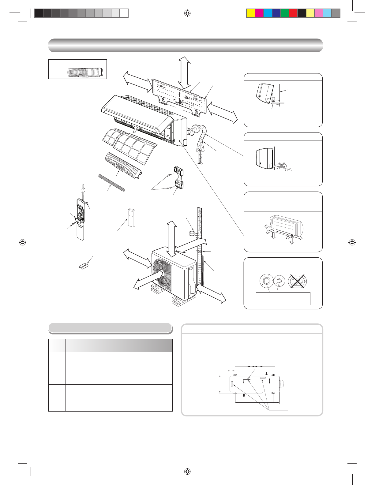
Optional Installation Parts
• Secure the outdoor unit with fi xing bolts and nuts if the unit is likely to be
exposed to a strong wind.
• Use Ø8 mm or Ø10 mm anchor bolts and nuts.
• If it is necessary to drain the defrost water, attach drain nipple 9 and cap
water proof ! to the bottom plate of the outdoor unit before installing it.
Fixing bolt arrangement of outdoor unit
Insulate the refrigerant pipes separately
with insulation, not together.
2
3
8
6
4
Insert the cushion between the indoor
unit and wall, and tilt the indoor unit for
better operation.
For the rear left and left piping
Wall
Make sure to run the drain hose sloped
downward.
Do not allow the drain hose to get slack.
Cut the piping
hole sloped
slightly.
The auxiliary piping can be connected to
the left, rear left, rear right, right, bottom
right or bottom left.
Right
Rear
right
Bottom
right
Rear
left
Bottom left
Left
6 mm thick heat resisting
polyethylene foam
1
Batteries
Flat head
wood screw
Remote control holder
Vinyl tape
Apply after carrying
out a drainage test.
Wireless remote control
Saddle
Extension
drain hose
(Not available,
provided by installer)
Shield pipe
Filter
(Attach to the front panel.)
Air fi lter
Hook
Installation
plate
Hook
65 mm or more
170 mm or more
170 mm or more
600 mm or more
100 mm or more
100 mm or more
600 mm or more
600 mm or more
Remark :
• Detail of accessory and installation parts can see in the accessory
sheet.
• Some pictures might be different from the actual parts.
6 FILTER
N3KVR
5
Filter
8
Flat head
wood screw
&
(
Flat head
wood screw
Battery cover
The provided Remote Controller is a wireless type,
which also can be used as a wire.
Please see “How to Connect The Remote Controller
for Wired Operation”, in case of wired control is
required.
Drain outlet
Air inlet
Air outlet
125 mm
108 mm
Ø25 mm
28 mm
320 mm
86 mm
102 mm
600 mm
90 mm
Book 1110251262-1.indb 2Book 1110251262-1.indb 2 7/13/12 8:59 AM7/13/12 8:59 AM
EN
ES
FR
IT
DE
PT
PL
CZ
RU
CR
HU
TR
NL
GR
SV
FI
NO
DK
RO
BG
EE
LV
SK
SI
3
7
65 mm
100 mm
45°
45°
75°
(Side view) (Top view)
Indoor unit
Reception range
Remote
control
Remote
control
Reception
range
Indoor unit
INDOOR UNIT
INDOOR UNIT
Installation Place
• Direct sunlight to the indoor unit’s wireless receiver should be avoided.
• The microprocessor in the indoor unit should not be too close to RF
noise sources.
(For details, see the owner’s manual.)
Remote control
• A place where there are no obstacles such as a curtain that may block the
signal from the indoor unit
• Do not install the remote control in a place exposed to direct sunlight or close
to a heating source such as a stove.
• Keep the remote control at least 1 m apart from the nearest TV set or stereo
equipment. (This is necessary to prevent image disturbances or noise
interference.)
• The location of the remote control should be determined as shown below.
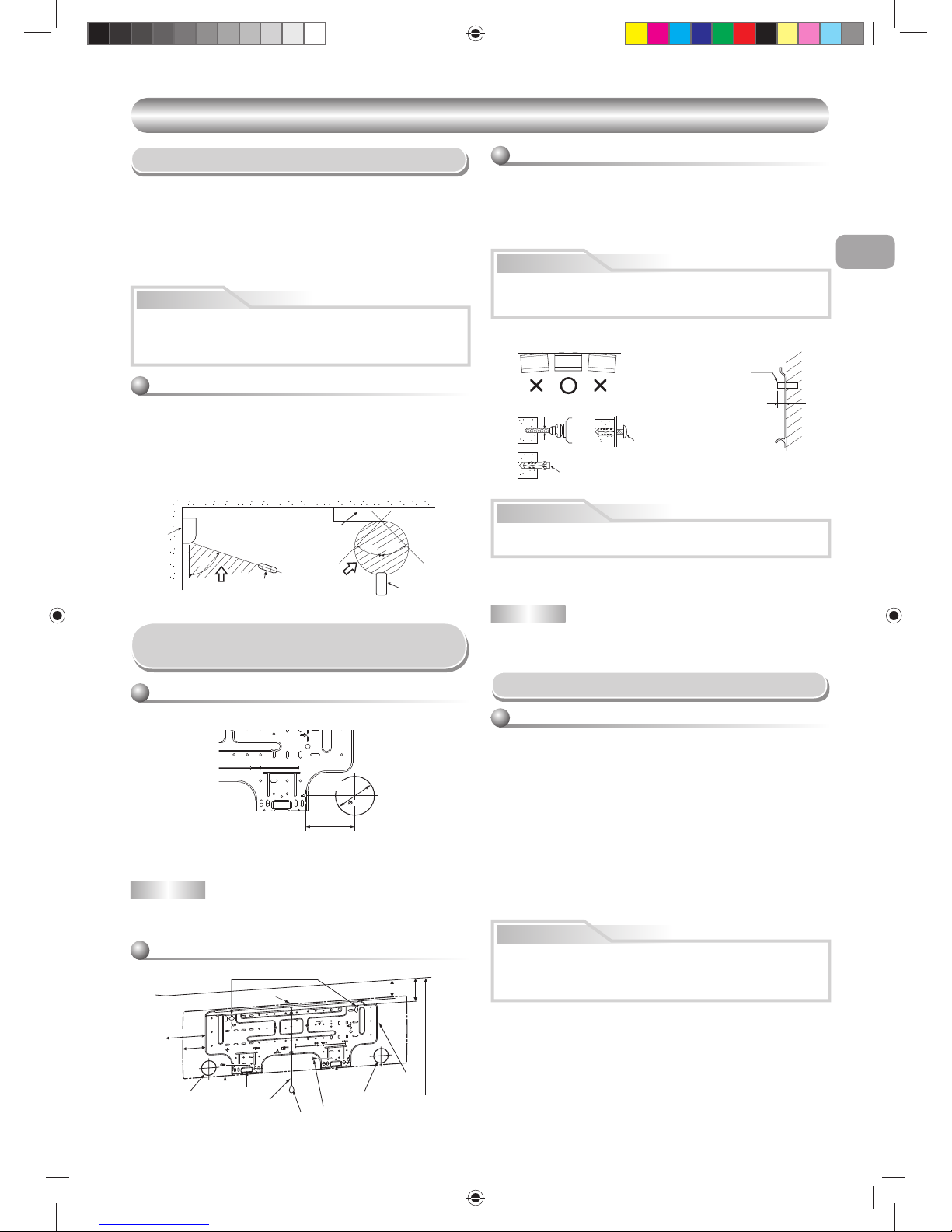
Cutting a Hole and Mounting
Installation Plate
NOTE
• When drilling a wall that contains a metal lath, wire lath or metal plate, be sure
to use a pipe hole brim ring sold separately.
Cutting a hole
When installing the refrigerant pipes from the rear
Mounting the installation plate
When the installation plate is directly mounted
on the wall
1. Securely fi t the installation plate onto the wall by screwing it in the upper and
lower parts to hook up the indoor unit.
2. To mount the installation plate on a concrete wall with anchor bolts, use the
anchor bolt holes as illustrated in the below fi gure.
3. Install the installation plate horizontally in the wall.
When installing the installation plate with a mounting screw, do not use the
anchor bolt holes. Otherwise, the unit may fall down and result in personal
injury and property damage.
1. After determining the pipe hole position on the mounting plate (), drill the
pipe hole (Ø65 mm) at a slight downward slant to the outdoor side.
• A place which provides the spaces around the indoor unit as shown in the
diagram
• A place where there are no obstacles near the air inlet and outlet
• A place which allows easy installation of the piping to the outdoor unit
• A place which allows the front panel to be opened
• The indoor unit shall be installed as top of the indoor unit comes to at least
2 m height. Also, it must be avoided to put anything on the top of the indoor
unit.
CAUTION
CAUTION
Failure to fi rmly install the unit may result in personal injury and property
damage if the unit falls.
• In case of block, brick, concrete or similar type walls, make 5 mm dia. holes
in the wall.
• Insert clip anchors for appropriate mounting screws 7.
NOTE
• Secure four corners and lower parts of the installation plate with 4 to 6
mounting screws to install it.
CAUTION
Wiring Connection
Wiring of the connecting cable can be carried out without removing
the front panel.
1. Remove the air inlet grille.
Open the air inlet grille upward and pull it toward you.
2. Remove the terminal cover and cord clamp.
3. Insert the connecting cable (according to the local cords) into the pipe
hole on the wall.
4. Take out the connecting cable through the cable slot on the rear panel so
that it protrudes from the front show on the fi gure below.
5. Insert the connecting cable fully into the terminal block and secure it
tightly with screws.
6. Tighten fi rmly but not over 1.2 N·m (0.12 kgf·m).
7. Secure the connecting cable with the cord clamp.
8. Fix the terminal cover, rear plate bushing and air inlet grille on the indoor
unit.
How to connect the connecting cable
• Be sure to refer to the wiring system diagram labeled inside the front
panel.
• Check local electrical cords and also any specifi c wiring instructions or
limitations.
CAUTION
The center of the pipe
hole is above the arrow.
Pipe hole
1
7
Anchor bolt holes
Hook
Hook
Hook
Pipe hole
Pipe hole
Installation
plate
Mounting screw
Weight
Indoor unit
Thread
2 m or more from fl oor
82.5
62
170
85
Installation plate
(Keep horizontal direction.)
5 mm dia. hole
Clip anchor
(local parts)
Mounting screw
Ø4 x 25R
Anchor bolt
Projection
15 mm or less
Book 1110251262-1.indb 3Book 1110251262-1.indb 3 7/13/12 8:59 AM7/13/12 8:59 AM
4
NOTE
• Use stranded wire only.
• Wire type : More than H07RN-F or 60245 IEC66 (1.0 mm2 or more)
1. Open the air inlet grille upward.
2. Securely remove two screws at the front panel.
3. Slightly open the lower part of the front panel then pull the upper part of
the front panel toward you to remove it from the rear plate as shown on
fi gure 1.
4. After removing the front panel, remove the Display unit and open the
cover as shown on fi gure 2 and 3.
5. Arrange the control wire as detail and specifi cation as shown on fi gure
4.
6. Securely connect the control wire to terminal of Display unit board as
shown on fi gure 5 (tighten fi rmly but not over 0.12 N·m (0.01 kgf·m)).
7. Set the control wire throughout at slot on front cover of Display unit then
reassembly Display with main casing by reverse process of fi gure 2 and
3. Make sure the control wire must not be pressed by front and rear
cover of Display unit.
8. Set the control wire out from indoor unit same portion as power supply
and connecting cable as shown on fi gure 6.
9. Reassembly the indoor unit by reverse process of 1 to 3.
Indoor unit
Control wire
Remote controller
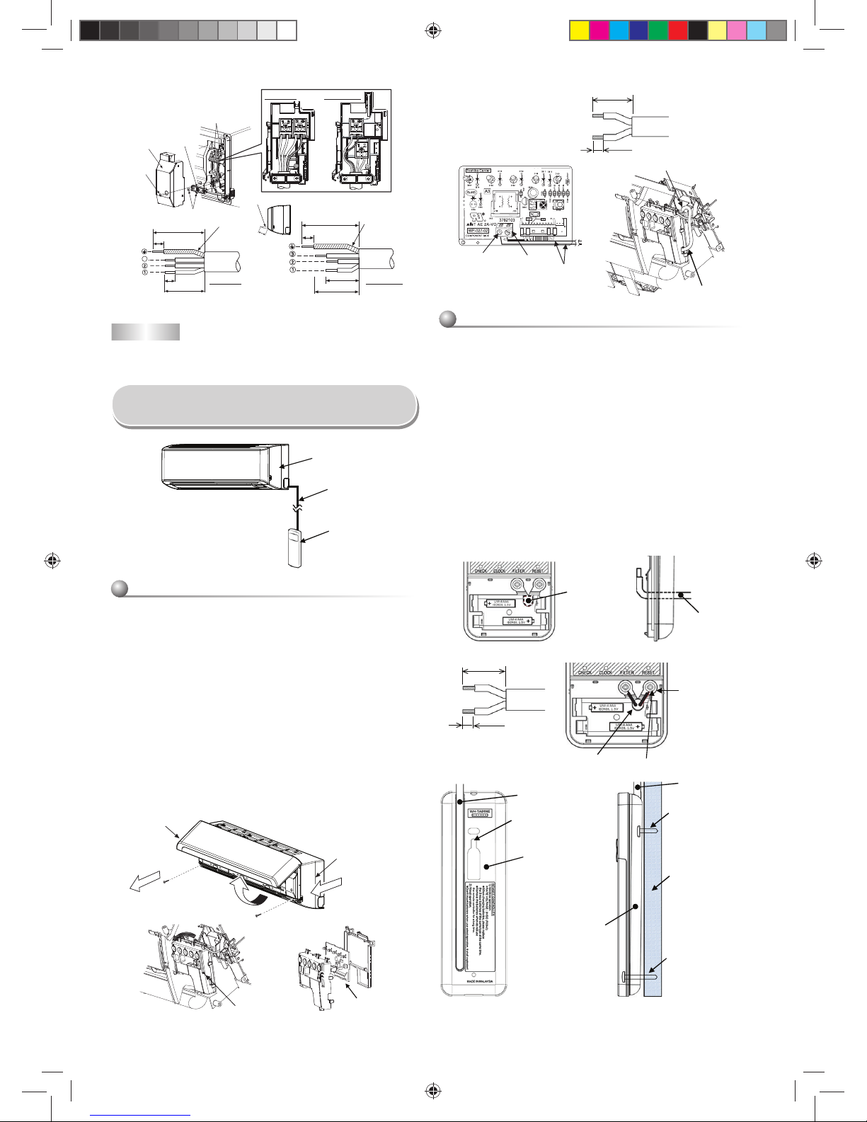
How to Connect Remote Controller
for Wire Operation
For indoor unit
Air inlet grille
Front panel
Display board
1
23
Display unit
1. Remove cover of remote controller by sliding down and take it out.
2. If batteries are exist, please take them out. The combination of using
wire controller and batteries may cause of batteries explosion.
3. Make hole for insert control wire by use screwdriver break the polyester
sheet as shown on fi gure 7.
4. Insert control wire from rear side of remote controller as shown on
fi gure 8.
5. Fix control wire which arrange as shown on fi gure 9 and ! to terminal
by provided screws (tighten fi rmly but not over 0.25 N·m (0.03 kgf·m)).
6. Set control wire through gutter way at rear side of remote controller as
shown on fi gure ".
7. Fix provided screw (Ø3.1×16L) on the wall to hang remote controller as
shown on fi gure #.
8. Mark and arrange hole for fi x below screw (Ø3.1×25L) as shown on
fi gure #.
9. Assembly battery cover which provided with accessory bag then use
provide screw (Ø3.1×25L) to fi x battery cover together with wall as
shown on fi gure $ (tighten fi rmly but not over 0.15 N·m (0.02 kgf·m)).
10. Reassembly cover of remote controller.
For remote controller
* Wire size 28-22AWG
or 0.08-0.32 mm
2
Outer diameter not over 4.7 mm,
control wire length less than 30 m.
70 mm
5 mm
4
65
Terminal
Control wire
Notch for wire out
Control wire
Tighten fi rmly but
not over 0.12 N.m
(0.01 kgf.m)
78
Polyester sheet
close hole for
insert control wire
Control wire
Control wire
Hole for hang
remote controller
Remote controller
Control wire
Screw (Ø3.1×16L)
for hang remote
controller
Wall
Screw (Ø3.1×25L)
for fi x battery cover
Remote controller
9
"
!
#
Control wire
Terminal
* Wire size 28-22AWG
or 0.08-0.32 mm
2
Outer diameter not over 4.7 mm,
control wire length less than 30 m.
30 mm
10 mm
Tighten fi rmly but
not over 0.25 N.m
(0.03 kgf.m)
CAUTION
• Be sure to install control wire along
the wall so that there is no slack and
fi x remote controller on the wall.
Stripping length of the connecting cableStripping length of the connecting cable
3
3
Screw
Terminal cover
Cord
clamp
Terminal block
Earth line
Earth line
Screw
100 mm
100 mm
10 mm
10 mm
45 mm
10 mm
90 mm
90 mm
Connecting cable
about 20 cm
For N3KV
For N3KV
For N3KVR
For N3KVR
Book 1110251262-1.indb 4Book 1110251262-1.indb 4 7/13/12 8:59 AM7/13/12 8:59 AM
 Loading...