

Page 1

Toshiba Personal Computer
Qosmio F40/F45
(PQF43x)
(PQF44x)
(PQF46x)
(PQF47x)
Maintenance Manual
TOSHIBA CORPORATION
Qosmio F40/F45 Maintenance Manual
S/ No
Page 2

Copyright
© 2007 by Toshiba Corporation. All rights reserved. Under the copyright laws, this manual
cannot be reproduced in any form without the prior written permission of Toshiba. No patent
liability is assumed with respect to the use of the information contained herein.
Toshiba Qosmio F40/F45 Maintenance Manual
First edition May 2007
Disclaimer
The information presented in this manual has been reviewed and validated for accuracy. The
included set of instructions and descriptions are accurate for the Qosmio F40/F45 at the time
of this manual's production. However, succeeding computers and manuals are subject to
change without notice. Therefore, Toshiba assumes no liability for damages incurred
directly or indirectly from errors, omissions, or discrepancies between any succeeding
product and this manual.
Trademarks
Intel and Pentium are registered trademarks of Intel Corporation.
IBM, IBM PC/XT, PC/AT, PS/2 and OS/2 are registered trademarks of IBM Corporation.
Windows XP home edition are registered trademarks of Microsoft Corporation.
Sound Blaster and Pro are trademarks of Creative Technology Ltd.
UNIX is a registered trademark of X/Open Company Ltd.
NetWare are registered trademarks of Novell, Inc.
All other properties are trademarks or registered trademarks of their respective holders.
ii Qosmio F40/F45 Maintenance Manual
Page 3
Preface
This maintenance manual describes how to perform hardware service maintenance for the
Toshiba Personal Computer Qosmio F40/F45, referred to as Qosmio F40/F45 in this manual.
The procedures described in this manual are intended to help service technicians isolate
faulty Field Replaceable Units (FRUs) and replace them in the field.
SAFETY PRECAUTIONS
Four types of messages are used in this manual to bring important information to your
attention. Each of these messages will be italicized and identified as shown below.
DANGER: “Danger” indicates the existence of a hazard that could result in death or
serious bodily injury, if the safety instruction is not observed.
WARNING: “Warning” indicates the existence of a hazard that could result in bodily
injury, if the safety instruction is not observed.
CAUTION: “Caution” indicates the existence of a hazard that could result in property
damage, if the safety instruction is not observed.
NOTE: “Note” contains general information that relates to your safe maintenance
service.
Improper repair of the computer may result in safety hazards. Toshiba requires service
technicians and authorized dealers or service providers to ensure the following safety
precautions are adhered to strictly.
Be sure to fasten screws securely with the right screwdriver. If a screw is not fully
fastened, it could come loose, creating a danger of a short circuit, which could cause
overheating, smoke or fire.
If you replace the battery pack, RTC battery or backup battery, be sure to use only the
same model battery or an equivalent battery recommended by Toshiba. Installation
of the wrong battery can cause the battery to explode.
Qosmio F40/F45 Maintenance Manual iii
Page 4

The manual is divided into the following parts:
Chapter 1 Hardware Overview describes the Qosmio F40/F45 system unit and
each FRU.
Chapter 2 Troubleshooting Procedures explains how to diagnose and resolve
FRU problems.
Chapter 3 Test and Diagnostics describes how to perform test and diagnostic
operations for maintenance service.
Chapter 4 Replacement Procedures describes the removal and replacement of the
FRUs.
Appendices The appendices describe the following:
Handling the LCD Module
Board Layout
Pin Assignments
Keyboard scan/character codes
Key Layout
BIOS Rewrite Procedures
EC/KBC Rewrite Procedures
iv Qosmio F40/F45 Maintenance Manual
Page 5

Conventions
This manual uses the following formats to describe, identify, and highlight terms and
operating procedures.
Acronyms
On the first appearance and whenever necessary for clarification acronyms are enclosed in
parentheses following their definition. For example:
Read Only Memory (ROM)
Keys
Keys are used in the text to describe many operations. The key top symbol as it appears on
the keyboard is printed in boldface type.
Key operation
Some operations require you to simultaneously use two or more keys. We identify such
operations by the key top symbols separated by a plus (+) sign. For example, Ctrl + Pause
(Break) means you must hold down Ctrl and at the same time press Pause (Break). If
three keys are used, hold down the first two and at the same time press the third.
User input
Text that you are instructed to type in is shown in the boldface type below:
DISKCOPY A: B:
The display
Text generated by the XXXXX that appears on its display is presented in the type face
below:
Format complete
System transferred
Qosmio F40/F45 Maintenance Manual v
Page 6

Chapter 1 Hardware Overview
Page 7

1 Hardware Overview 1.1 Features
Qosmio F40/F45 Maintenance Manual 2
Page 8

1.1 Features 1 Hardware Overview
Chapter 1 Contents
1.1 Features......................................................................................................................... 5
1.2 System Unit Components ........................................................................................... 14
1.3 2.5-inch HDD.............................................................................................................. 22
1.4 DVD Super Multi (+-R Double Layer)....................................................................... 23
1.5 HD DVD-ROM........................................................................................................... 25
1.6 HD DVD-R................................................................................................................. 26
1.7 Power Supply.............................................................................................................. 27
1.8 Batteries ...................................................................................................................... 28
1.1.1 Main Battery.......................................................................................... 28
1.1.2 Battery Charging Control...................................................................... 28
1.1.3 RTC Battery .......................................................................................... 29
Qosmio F40/F45 Maintenance Manual 3
Page 9

1 Hardware Overview 1.1 Features
Figures
Figure 1-1A ID Parts Description Placement Part A........................................................... 10
Figure 1-1B ID Parts Description Placement Part B ...........................................................11
Figure 1-2 Computer Block Diagram ...............................................................................12
Figure 1-3 System Board Configurations .........................................................................13
Figure 1-4 System Unit Block Diagram ........................................................................... 15
Figure 1-5 SATA HDD.....................................................................................................22
Figure 1-6 DVD Super Multi Drive..................................................................................23
Tables
Table 1-1 HDD Specifications.........................................................................................22
Table 1-2 DVD Super Multi Drive Specifications .......................................................... 23
Table 1-3 HD DVD-ROM Drive Specifications .............................................................25
Table 1-4 HD DVD-R Drive Specifications.................................................................... 26
Table 1-5 Battery Specifications ..................................................................................... 28
Table 1-6 Quick/Normal Charging Time ........................................................................ 29
Qosmio F40/F45 Maintenance Manual 4
Page 10

1.1 Features 1 Hardware Overview
1.1 Features
The Toshiba Qosmio F40/F45 a full size notebook PC based on the Core2 Duo Processor and
Celeron M Processor, providing high-speed processing capabilities and advanced features.
The computer employs a Lithium Ion battery that allows it to be battery-operated for a longer
period of time. The display uses 15.4-inch WXGA LCD panel, at a resolution of 1280 by
800 pixels. The uPGA socket supports BTO/CTO for the CPU so that the system can be
designed to suit your needs.
The computer has the following features:
Processor
The CPU is the Core2 Duo Processor and Celeron M Processor.
Core2 Duo Processor (800MHz)
T7100(1.80G)/T7300(2.00G)/
T7500(2.20G)/T7700(2.40G) Hz
Celeron M Processor (533MHz)
540(1.86G)/550(2.00G) Hz
Host Bridge System Controller
System Controller: Intel Crestline PM965/GM965/GL960 + ICH8M.
Graphics
Intel GM965/GL960 integrated graphic or PM965 with nVIDIA NB8P-GS/NB8MGS.
Memory
The computer has two SO-DIMMs slot comes standard with DDRII-667MHz module.
It supports PC2-5300 and uses SO-DIMMs (DDRII SDRAM) driven at 1.8 V,
accepting BTO/CTO for your memory requirements. It can incorporate up to 4 GB of
main memory.
Using the following sizes of memory modules:
y 512 MB (32M×16×8P)/667 MHZ
Qosmio F40/F45 Maintenance Manual 5
Page 11

1 Hardware Overview 1.1 Features
y 1024 MB (64M×8×16P)/667 MHZ
y 2048 MB (64Mx16x16P)/667 MHZ
Hard Disk Drive (HDD)
The computer accommodates 9.5 mm and 12.5 mm two kinds of height HDD types
with following storage capacities:
y 60 GB (9.5 mm thick) SATA (5,400rpm)
y 80 GB (9.5 mm thick) SATA (5,400rpm)
y 100 GB (9.5 mm thick) SATA (5,400rpm)
y 120 GB (9.5 mm thick) SATA (5,400rpm)
y 160 GB (9.5 mm thick) SATA (5,400rpm)
y 160 GB (12.5 mm thick ) SATA (4,200rpm)
y 200 GB (9.5 mm thick) SATA (4,200rpm)
y 250 GB (12.5 mm thick) SATA (4,200rpm)
y 300 GB (12.5 mm thick) SATA (4,200rpm)
ODD
The computer accommodates a fixed 12.7 mm height ODD with one of following
types:
y DVD Super Multi +-R Double Layer drive
y DVD Super Multi +-R Double Layer with Label Flash Support drive (BTO)
y HD DVD-ROM with Super Multi drive
y HD DVD-R with Super Multi drive
Display
The LCD displays available come with one of following two types:
y 15.4” WXGA CSV 1-Lamp 200nits color display, resolution 1280×800
y 15.4” WXGA CSV 2-Lamps 500nits color display, resolution 1280×800
Keyboard
The keyboard supports 30 kinds of country keyboards.
Qosmio F40/F45 Maintenance Manual 6
Page 12

1.1 Features 1 Hardware Overview
Battery
The computer has a removable 6 Cell Lithium Ion battery pack and an internal RTC
battery (rechargeable).
Universal Serial Bus (USB) Ports
The computer has four USB 2.0 ports. It is supported to daisy-chain a maximum of
127 USB devices. The serial data transfer rate is 480 Mbps or 12 Mbps and 1.5 Mbps.
These ports support PnP installation and hot plugging.
External Monitor Port
A 15-pin external monitor port is provided, through which the computer automatically
recognizes an external VESA DDC 2B compatible monitor.
S Video Out Port
The S Video out port lets you transfer video data to external devices.
HDMI Out Port (BTO)
A HDMI monitor can be connected to the HDMI out port on the computer.
Video-In Jack
The Video-In Jack lets you transfer NTSC or PAL data to the computer.
TV Antenna Port
The TV Antenna Port lets you connect a TV Antenna.
PC Card Slot (BTO)
A PC Card slot is provided to hold PC Card Standard Type II (5.0 mm) card, capable
of using a variety of PC Cards including 16-bit Multiple Function PC Cards and 32bit Card Bus Cards.
PC card HDD boot does not be supported.
Qosmio F40/F45 Maintenance Manual 7
Page 13

1 Hardware Overview 1.1 Features
Express Card Slot (BTO)
The ICH8M provides PCI Express root ports which are compliant to the PCI Express
Base Specification, Revision 1.0a. The root port supports 2.5 Gb/s bandwidth in each
direction (5 Gb/s concurrent) and two virtual channels for full isochronous data
support.
Multiple Digital Media Card Slot
This computer is equipped with Multiple Digital Media Card Slot that can
accommodate SD/ Mini-SD/ Micro-SD/ SD-IO/ SDHC/ MS/ MS Pro/ MMC/ XD
memory cards. This slot is for your memory card requirements to provide memory
card read on your computer.
Toshiba Pointing Device
Toshiba Pointing Device has one kind of Synaptic Touchpad.
Sound System
The Realtek ALC888 integrated audio controller supports multimedia. The sound
system contains the following:
y Stereo speakers
y Headphone jack
y Internal microphone
y External microphone jack
Line-In Jack
The Line-In Jack lets you transfer analogue sound to the computer.
LAN (BTO)
The internal LAN board supports 10/100Mbit, enabling connection to a LAN at up to
100Mbps. It also supports Wake-up on LAN from S3/S4/S5 and PXE boot support.
The LAN board has RJ45 jack to directly accommodate a LAN cable.
Wireless LAN
Qosmio F40/F45 Maintenance Manual 8
Page 14

1.1 Features 1 Hardware Overview
The internal Mini Card slot supports IEEE802.11g (MOW) / IEEE802.11ag (MOW) /
IEEE802.11ag (ROW) / IEEE802.11ag (JPN) / IEEE802.11agn (MOW) /
IEEE802.11agn (ROW) / IEEE802.11agn (JPN) card. The Antenna has three wires
dual band antenna support for BTO.
Internal Modem (BTO)
The computer contains a MDC, enabling data and fax communication. It supports
ITU- T V.90 (for rest countries)/V.92 (America, Canada, UK, Germany & France).
The transfer rates are 56 Kbps for data reception, 33.6 Kbps for data transmission and
14,400 bps for fax transmission. Note, however, that the actual speed depends on the
line quality. The RJ11 modem jack is used to accommodate a telephone line.
IEEE 1394
The IEEE 1394 serial data transfer rate is 400 Mbps, this port supports hot plugging.
Finger Print (BTO)
This product has a fingerprint utility installed for the purpose of enrolling and
recognizing fingerprints. By enrolling the ID and password to the fingerprint authentication device, it is no longer necessary to input the password from the keyboard.
Just by swiping the finger against the fingerprint sensor.
Internal Camera (BTO)
The computer has an internal camera. The camera has 1.3Mpix resolution support.
ROBSON Card (BTO)
Robson is Intel’s platform non-volatile memory (NVM) disk-cache accelerator
which delivers a fast cold boot as well resumes from hibernation while saving
power. It also accelerates application loading and run time through intelligent file
caching. The computer has 512 MB or 1 GB sizes of Robson card modules.
Qosmio F40/F45 Maintenance Manual 9
Page 15
1 Hardware Overview 1.1 Features
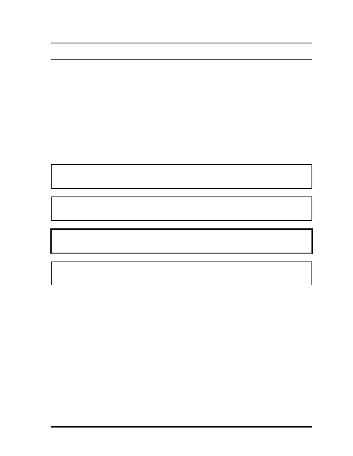
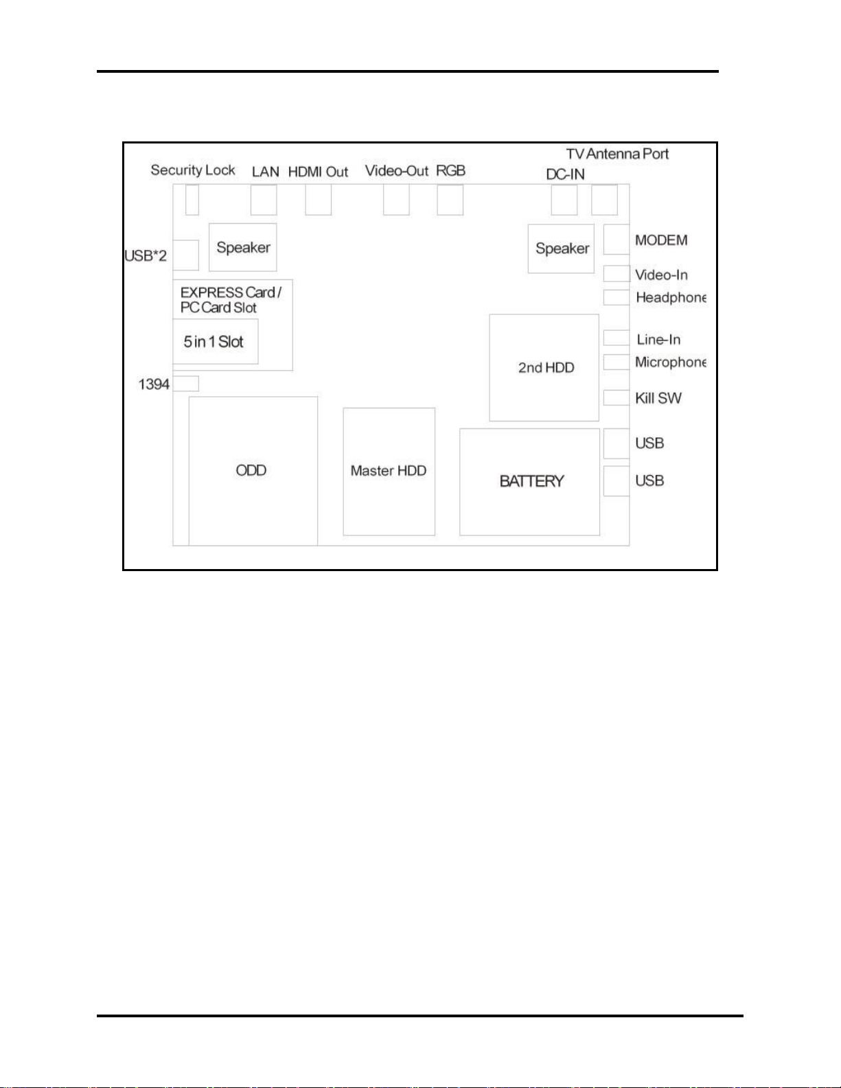
Figures 1-1A/1-1B/1-2/1-3 and 1-4 show the computer and its system unit
configuration, respectively.
Figure 1-1A ID Parts Description Placement Part A
Qosmio F40/F45 Maintenance Manual 10
Page 16
1.1 Features 1 Hardware Overview
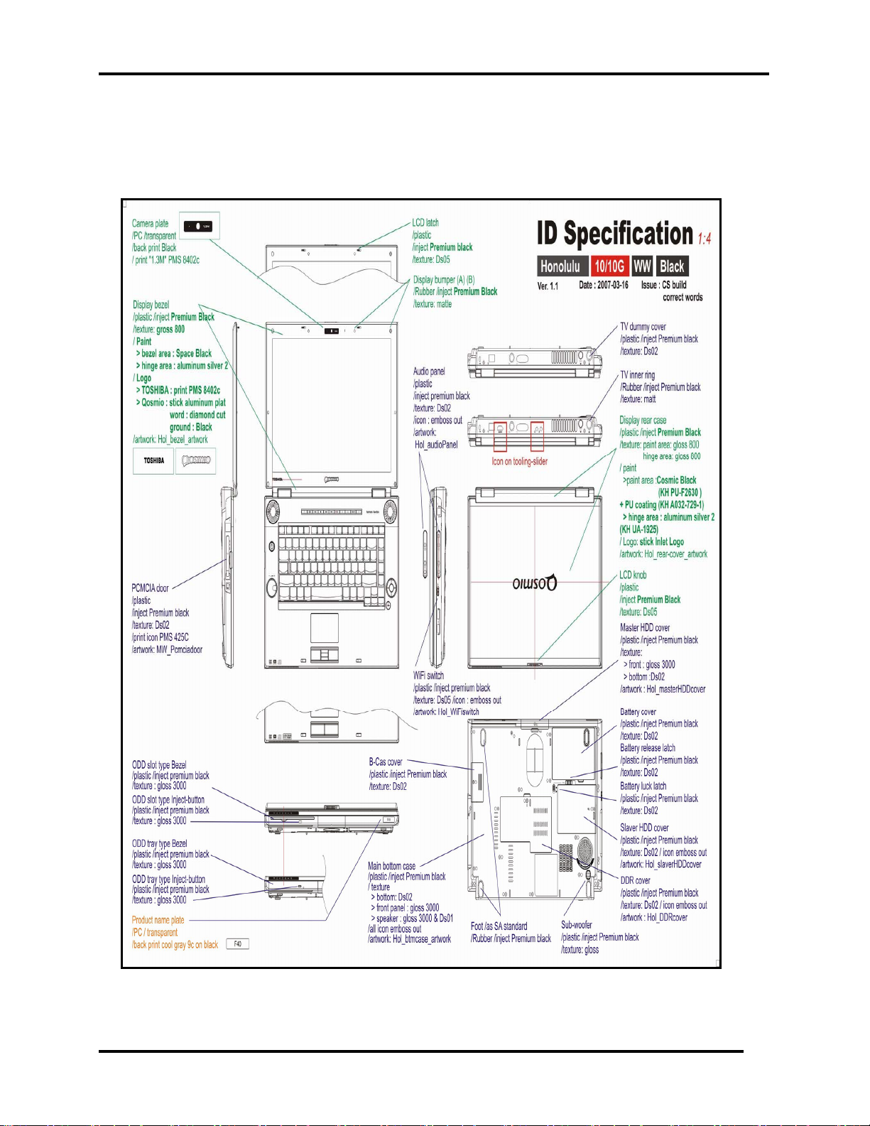
Figure 1-2B ID Parts Description Placement Part B
Qosmio F40/F45 Maintenance Manual 11
Page 17
1 Hardware Overview 1.1 Features
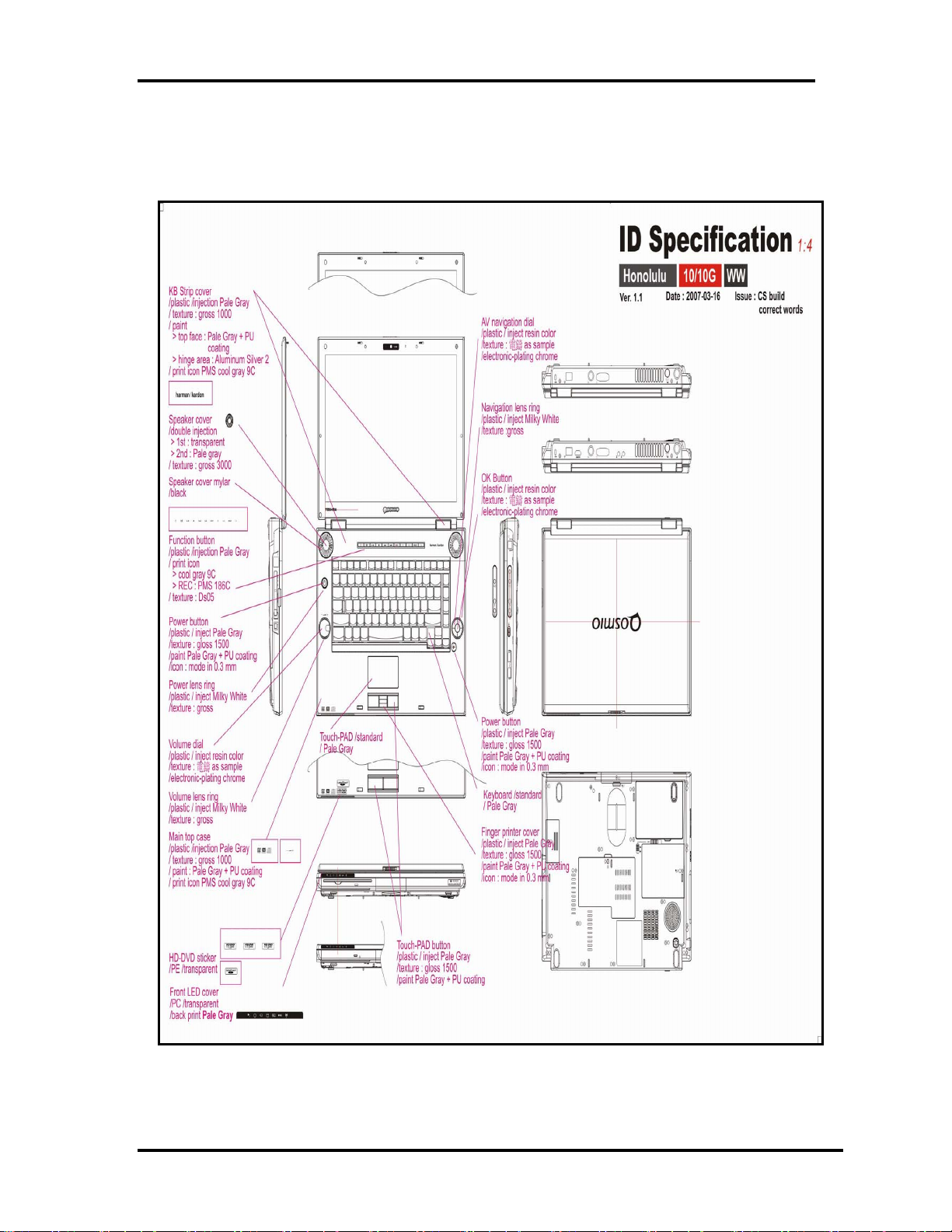
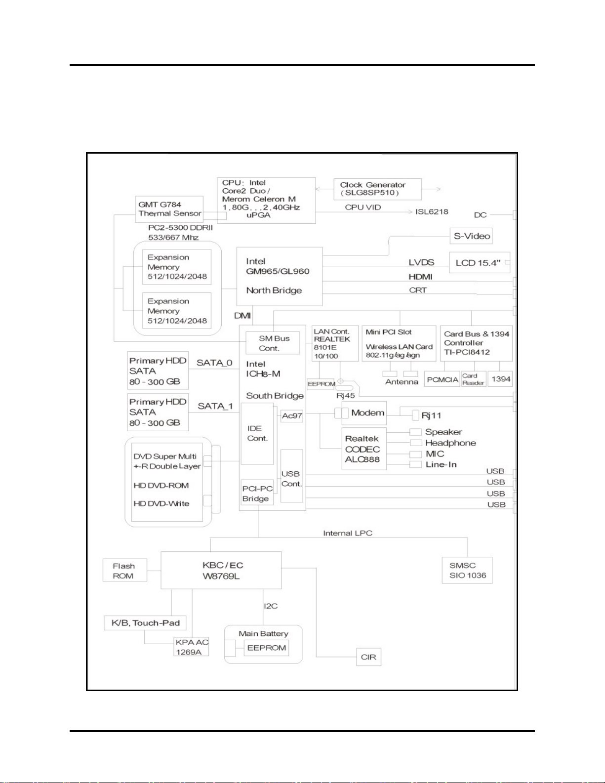
Figure 1-3 Computer Block Diagram
Qosmio F40/F45 Maintenance Manual 12
Page 18
1.1 Features 1 Hardware Overview
Figure 1-4 System Board Configurations
Qosmio F40/F45 Maintenance Manual 13
Page 19
1 Hardware Overview 1.2
System Unit Components
1.2 System Unit Components
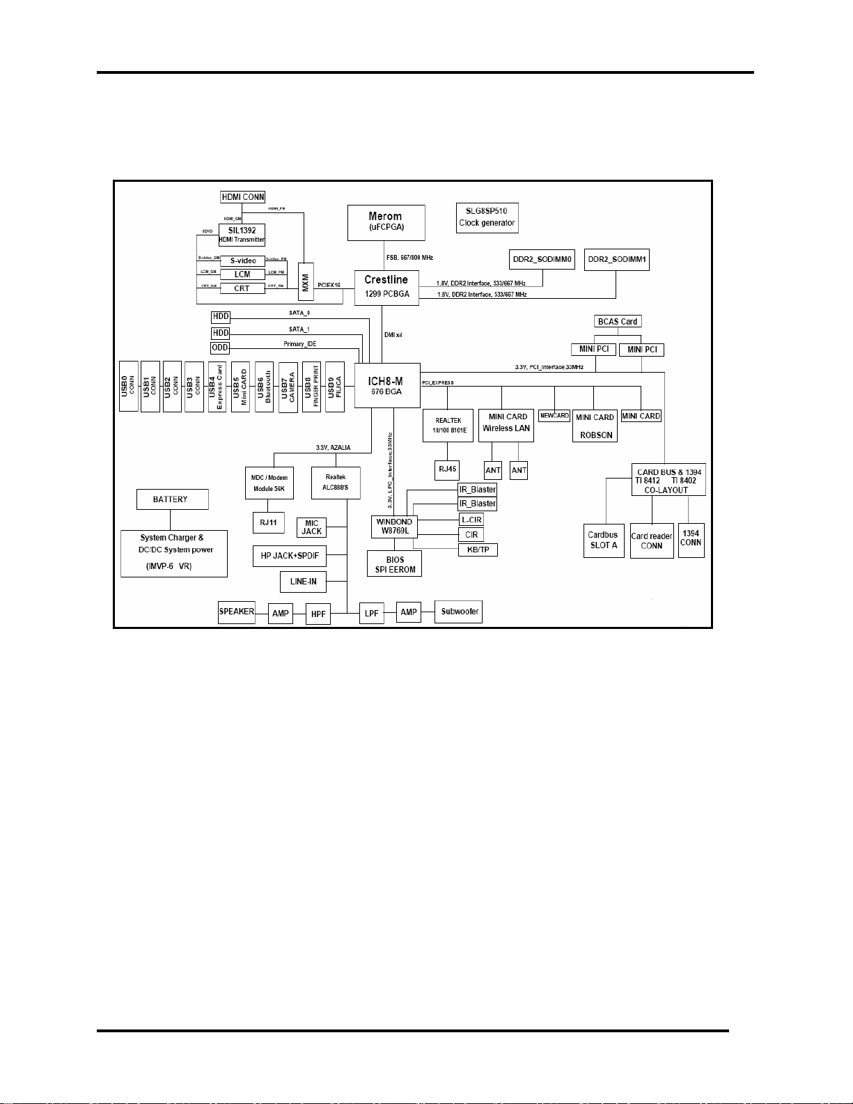
Figure 1-4 is Block Diagram of the System Unit
Qosmio F40/F45 Maintenance Manual 14
Page 20

1.2 System Unit Components 1 Hardware Overview
Figure 1-5 System Unit Block Diagram
Qosmio F40/F45 Maintenance Manual 15
Page 21

1 Hardware Overview 1.2
System Unit Components
The system unit of the computer consists of the following components:
Processor: Core2 Duo Processor and Celeron M Processor.
y Core2 Duo Processor (800MHz)
− Core speed: 1.80/2.00/2.20/2.40 GHz
− System bus: 800 MHz
− On-die level 2 cache: 2 MB (1.8 GHz)
− On-die level 2 cache: 4 MB (2.0/2.2/2.4 GHz)
y Celeron M Processor (533MHz)
− Core speed: 1.86/2.00 GHz
− System bus: 533 MHz
− On-die level 2 cache: 1 MB
Memory
Two expansion memory slots are provided. They can hold 512/1024/2048MB expansion
memory modules available as options to grow up to 4.0 GB.
y PC2-5300/667MHz DDRII SDRAM supported
y 512/1024/2048MB modules supported
− 512 MB (32M x 16 x 8P)
− 1024 MB (64M x 8 x 16P)
− 2048 MB (64M x 16 x 16P)
y 1.8 volt operation
y No parity bit
y 64-bit data transfer
BIOS ROM (Flash EEPROM)
y 8Mb x 1 chip (1024KB flash parts)
− 64.00Kb used for EC BIOS
− 8.00Kb used for ESCD
− 15.13Kb used for Memory Initial Code
− 12.71Kb used for ACPI
− 30.03Kb used for CPU update module
− 64.03Kb used for Intel VGA BIOS
− 55.28Kb used for Finger Printer ROM
− 51.44Kb used for string data
− 39.13Kb used for nVidia G84
Qosmio F40/F45 Maintenance Manual 16
Page 22

1.2 System Unit Components 1 Hardware Overview
− 39.03Kb used for nVidia G86
− 24.01Kb used for PXE ROM
− 35.65Kb used for SMI
− 37.86Kb used for PNP Code
− 11.55Kb used for BIOS Code
− 21.04Kb used for USB
− 16.17Kb used for Setup
− 9.31Kb used for AHCI
− 3.82Kb used for Display Engine
− 1.09Kb used for Decode Code
− 0.52Kb used for Compress Code
− 6.15Kb used for Pre-Shadow Code
− 29.23Kb used for ROM Executable
− 64.00Kb used for Bootblock
− 866.04Kb used for Used Size
− 157.96Kb used for Free Size
System Controllers
y North Bridge: Intel Crestline PM965/GM965/GL960
− CPU Interface and Control
− System Memory Support
− PCI Express* Graphics (PEG) Interface
− Integrated Display Interface Support
− Internal Graphics Features (GM965/GL960)
− Direct Media Interface (DMI)
− Power Management
− Security and Manageability
− Serial ATA Interface
− ICH8 Audio Control
y South Bridge: Intel ICH8-M
− Direct Media Interface (DMI)
− PCI Express* Interface
− Serial ATA (SATA) Controller
− Advanced Host Controller Interface (AHCI)
− Intel Matrix Storage Technology
− PCI Interface
− IDE Interface
− Low Pin Count (LPC) Interface
− Serial Peripheral Interface (SPI)
− Compatibility Modules
− Advanced Programmable Interrupt Controller (APIC)
− Universal Serial Bus (USB) Controller
Qosmio F40/F45 Maintenance Manual 17
Page 23

1 Hardware Overview 1.2
System Unit Components
− LAN Controller
− RTC
− GPIO
− Enhanced Power Management
− Manageability
− System Management Bus (SMBus 2.0)
− Intel High Definition Audio Controller
− Integrated FAN Speed Control
Graphics Controller
Intel GM965/GL960 integrated graphics or PM965 with nVIDIA NB8P-GS / NB8M-GS,
nVIDIA graphics controller contains the following features:
y Unified Shader Architecture.
y Microsoft DirectX 10 Shader Model 4 Support.
y High efficiency integrated adaptable and programmable Video Processor.
y Integrated Bit Stream Processor.
y Best quality 10-bit display pipeline.
y Integrated HDMI 1.2a Support.
y Improved Internal Temperature Sensor.
y Improved Integrated Spread Spectrum Support.
PC Card Controller
y TI 8402/8412
− CardBus/PC Card Controller
− 16-bit PCMCIA and 32-bit CardBus
− SD/SDHC/MS/MS Pro/MMC/XD Card Controller
Audio Controller
Realtek ALC888 integrated audio controller supports multimedia. The sound system
contains the following features:
y Ten DAC channels support 16/20/24-bit PCM format for 7.1 sound playback, plus 2
channels of independent stereo sound output through the front panel output.
y 2 stereo ADCs support 16/20/24-bit PCM format.
y All DACs support 44.1 k/48 k/96 k/192 kHz sample rate.
y All ADCs support 44.1 k/48 k/96 k sample rate.
Qosmio F40/F45 Maintenance Manual 18
Page 24

1.2 System Unit Components 1 Hardware Overview
y Two independent 16/20/24-bit S/PDIF-Out converters support 44.1 k/48 k/96 k/192 kHz
sample rate.
y One 16/20/24-bit S/PDIF-In converter supports 44.1 k/48 k/96 k/192 kHz sample rate.
y High quality analog differential CD input.
y Support external PCBEEP input and built-in digital BEEP generator.
y Two jack detection pins each designed to detect up to 4 jacks.
y All analog jacks are stereo input and output re-tasking for analog plug & play.
y Built-in headphone amplifiers for each re-tasking jack.
y Two digital GPIOs and one analog GPIO for customized applications.
KBC/EC (Keyboard Controller/Embedded Controller)
A single KBC W8769 chip is used to serve as KBC/ EC and Super IO.
y KBC
− Scan controller function
− Interface controller function
y EC
− Power supply sequence control
− Overheat shutdown support
− LED control
− Beep control
− Device ON/OFF
− Cooling fan speed control
− Universal I/O port
− Battery capacity check
− Flash memory reprogramming function
− EC access interface
− I2C communication control
Battery EEPROM
y 24C02 equivalent (128 words x 16 bits, I2C interface) integrated in battery pack.
− Storing records of battery use
Clock Generator
y SLG8SP510
− Generating the clock signal required for the system
Qosmio F40/F45 Maintenance Manual 19
Page 25

1 Hardware Overview 1.2
System Unit Components
Modem Controller
Built-in MDC card with Askey. Functions of modem controller:
y Digital signal conductor protection
y Ring wake-up support
y Azalia interface
y Communication codes supported:
− For data communication:
V.90 (China)/V.92, data rates: 28kbps/56kbps
V.34 extended rates: 33.6K/2400/V.32 turbo, V.32 bits and fallbacks
− For fax:
V.17, V.27, V.29, V.34 and V.21 Channel 2, V.253 Class 1 fax
LAN Controller
y Realtek RTL8101E 10/100Mbit
− IEEE 802.3 10BASE-T/100BASE-TX compliant physical
layer interface
− IEEE 802.3u Auto-Negotiation support
− Digital Adaptive Equalization control
− 10BASE-T auto-polarity correction
− LAN Connect interface
− Automatic detection of “unplugged mode”
− Remote boot (PXE 2.1)
− Smart power down when link is not detected
Wireless LAN Controller
y Support following 3 kinds of mini PCI wireless LAN cards
− IEEE 802.11g
− IEEE 802.11ag
− IEEE 802.11agn
y Data Rate
− IEEE 802.11g: Standard 54M bps
− IEEE 802.11ag: Standard 54M bps
− IEEE 802.11agn: Standard 130M bps
y Frequency Channel
− IEEE802.11a: 2.4GHz
− IEEE802.11ag: 2.4GHz / 5.4GHz
Qosmio F40/F45 Maintenance Manual 20
Page 26

1.2 System Unit Components 1 Hardware Overview
− IEEE802.11agn: 2.4GHz / 5.4GHz
Qosmio F40/F45 Maintenance Manual 21
Page 27
1 Hardware Overview 1.3 2.5-inch HDD
1.3 2.5-inch HDD
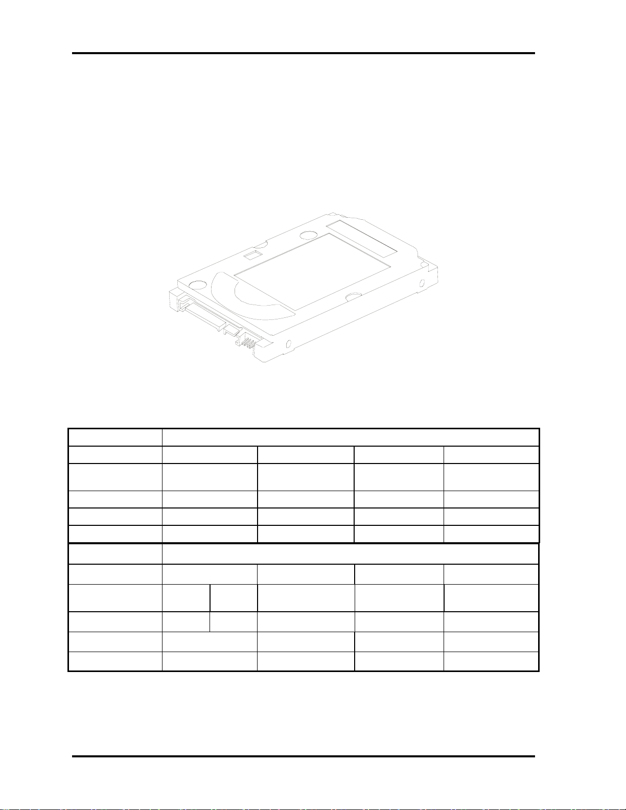
The computer contains an extremely low-profile and lightweight, high-performance HDD.
The HDD incorporates 9.5 mm / 12.5 mm height magnetic disk and mini-Winchester type
magnetic heads. The HDD interface conforms to Serial ATA. Storage capacities supported
are 60, 80, 100, 120, 160, 200, 250, 300 GB.
The HDD is shown in Figure 1-5 and some of its specifications are listed in Table 1-1.
Figure 1-6 SATA HDD
Table 1-1 HDD Specifications
Item Specifications
Capacity (GB)
Rotational Speed
(RPM)
Height
User Data Sectors
Bytes / Sector 512 512 512 512
Item
Capacity (GB)
Rotational Speed
(RPM)
Height
User Data Sectors
60 GB 80 GB 100 GB 120 GB
5400 rpm 5400 rpm 5400 rpm 5400 rpm
9.5 mm 9.5 mm 9.5 mm 9.5 mm
117,210,240 156,301,488 195,371,568 234,442,648
Specifications
160 GB 200 GB 250 GB 300 GB
4200 rpm 5400 rpm 4200 rpm 4200 rpm 4200 rpm
12.5 mm 9.5 mm 9.5 mm 12.5 mm 12.5 mm
312,581,808 390,721,968 488,397,168 586,072,368
Bytes / Sector 512 512 512 512
Qosmio F40/F45 Maintenance Manual 22
Page 28
1.4 DVD Super Multi (+-R Double Layer))
1 Hardware Overview
1.4 DVD Super Multi (+-R Double Layer)
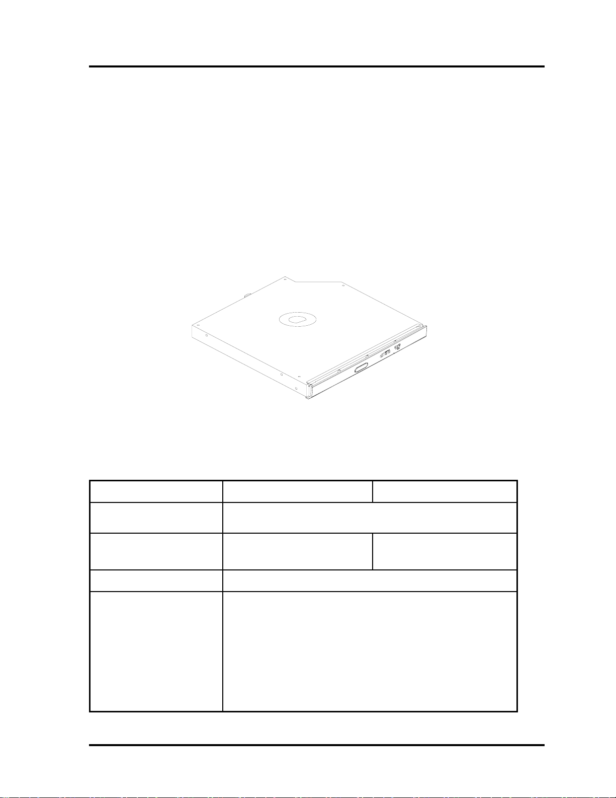
The DVD Super Multi drive accepts 12-cm (4.72-inch) and 8-cm (3.15-inch) discs. At
maximum, the drive can play back a DVD at 8x speed, read CD-ROM at 24x speed, and
write CD-R at 24x speed, CD-RW at 4x speed, US CD-RW at 24x speed, High Speed CDRW at 10x speed, DVD-R at 8x speed, DVD-RW at 6x speed, DVD+R at 8x speed, DVD+R
(Double Layer) at 4x speed, DVD-R (Double Layer) at 4x speed, DVD+RW at 8x speed and
DVD-RAM at 5x speed.
The DVD Super Multi drive is shown in Figure 1-6 and its specifications are listed in Table
1-2.
Table 1-2 DVD Super Multi Drive Specifications
Item DVD-ROM Mode CD-ROM Mode
Data Transfer Rate
(Mbytes/s)
Access Time (ms)
Average Random Access
Data Buffer Size (Mbytes)
Formats Supported
Figure 1-7 DVD Super Multi Drive
33.3 (U-DMA transfer mode 2)
16.6 (PIO mode 4, Multiword DMA mode 2)
130 130
2MB
DVD:
DVD-VIDEO, DVD-ROM, DVD-R, DVD-RW, DVD-RAM,
DVD+R, DVD+-R (Double Layer), DVD+RW.
CD:
CD-DA, CD-ROM, CD-R, CD-RW, CD-ROMXA, Photo CD (Multi-
Session), Video CD, CD-Extra (CD+), CD-Text.
Qosmio F40/F45 Maintenance Manual 23
Page 29

1 Hardware Overview 1.5
HD DVD-ROM
Qosmio F40/F45 Maintenance Manual 24
Page 30
1.4 DVD Super Multi (+-R Double Layer))
1 Hardware Overview
1.5 HD DVD-ROM
The HD DVD-ROM drive accepts 12-cm (4.72-inch) and 8-cm (3.15-inch) discs. At
maximum, the drive can play back a DVD at 8x speed, read HD DVD ROM at 1x speed, CDROM at 24x speed, and write CD-R at 16x speed, CD-RW at 4x speed, US CD-RW at 10x
speed, High Speed CD-RW at 10x speed, DVD-R at 4x speed, DVD-RW at 4x speed,
DVD+R at 4x speed, DVD+R (Double Layer) at 2.4x speed, DVD-R (Double Layer) at 2x
speed, DVD+RW at 4x speed and DVD-RAM at 3x speed.
The specifications of the HD DVD-ROM drive are listed in Table 1-3.
Table 1-3 HD DVD-ROM Drive Specifications
Item HD DVD-ROM Mode DVD-ROM Mode
Data Transfer Rate
(Mbytes/s)
Access Time (ms)
Average Random Access
Data Buffer Size (Mbytes)
Formats Supported
33.3 (U-DMA transfer mode 2)
16.7 (PIO mode 4, Multiword DMA mode 2)
330 160
8,126KB
DVD:
DVD-VIDEO, DVD-ROM, DVD-R, DVD-RW, DVD-RAM,
DVD+-R, DVD+-R (Double Layer), DVD+RW, HD DVD-ROM
CD:
CD-DA, CD-ROM, CD-R, CD-RW, CD-ROM XA, Photo CD (MultiSession), HS CD-RW,US CD-RW, Video CD, CD-Extra (CD+),
CD-Text, CD-MIDI, CD-I, CD-I Bridge.
Qosmio F40/F45 Maintenance Manual 25
Page 31

1 Hardware Overview 1.6
HD DVD-R
1.6 HD DVD-R
The HD DVD-R drive accepts 12-cm (4.72-inch) and 8-cm (3.15-inch) discs. At maximum,
the drive can play back a DVD at 8x speed, read HD DVD ROM at 1x speed, HD DVD-R at
1x speed ,CD-ROM at 24x speed, and write CD-R at 16x speed, CD-RW at 4x speed, US
CD-RW at 10x speed, High Speed CD-RW at 10x speed, HD DVD-R at 1x speed, DVD-R at
4x speed, DVD-RW at 4x speed, DVD+R at 4x speed, DVD+R (Double Layer) at 2.4x speed,
DVD-R (Double Layer) at 2x speed, DVD+RW at 4x speed and DVD-RAM at 3x speed.
The specifications of the HD DVD-R drive are listed in Table 1-4.
Table 1-4 HD DVD-R Drive Specifications
Item HD DVD-ROM Mode DVD-ROM Mode
Data Transfer Rate
(Mbytes/s)
Access Time (ms)
Average Random Access
Data Buffer Size (Mbytes)
Formats Supported
33.3 (U-DMA transfer mode 2)
16.7 (PIO mode 4, Multiword DMA mode 2)
330 180
8,126KB
DVD:
DVD-VIDEO, DVD-ROM, DVD-R, DVD-RW, DVD-RAM,
DVD+-R, DVD+-R (Double Layer), DVD+RW, HD DVD-ROM,
HD DVD-R, HD DVD-R (Double Layer).
CD:
CD-DA, CD-ROM, CD-R, CD-RW, CD-ROM XA, Photo CD (MultiSession), HS CD-RW,US CD-RW, Video CD, CD-Extra (CD+),
CD-Text, CD-MIDI, CD-I, CD-I Bridge.
Qosmio F40/F45 Maintenance Manual 26
Page 32

1.8 Batteries 1 Hardware Overview
1.7 Power Supply
The power supply unit provides many different voltages for the system board and performs the
following functions:
1. Power input monitor
y Checks whether the DC power supply (AC adapter) is connected to the computer.
y Checks whether the battery pack is connected to the computer.
y Monitors the DC power supply input voltage (AC Adapter output voltage).
2. Power supply's internal control
y Turns on and off the battery pack charging power supply.
y Issues a charging current instruction to the PWM control IC of the battery pack charging
power supply.
y Controls the supply of DC power supply input (AC Adapter output) to the power supply
unit.
y Controls the supply of power to the system block (load/logic circuit side).
y Controls forced shutdown if the power supply malfunctions.
3. Logic circuit control
y Instructs the gate array to enable/disable tuning the power on.
y Controls power-on/off operation.
4. Status display
y Turns on the Power LED (in Blue or AMBER).
y Battery indicator (in Blue or AMBER or AMBER Flash).
5. External interface
y Performs communication through the I2C bus (via the internal EC/KBC).
y Transfers the power supply operation mode.
6. Output monitor
y Monitors the voltage output to the system block (load/logic circuit side).
y Monitors the voltage, over voltage, input/output current of the battery pack.
y Monitors the internal temperature of the battery pack.
y Monitors the supply voltage from the AC adapter.
Qosmio F40/F45 Maintenance Manual 27
Page 33

1 Hardware Overview 1.7 Power Supply
1.8 Batteries
The computer has the following two types of batteries:
Main Battery Pack
Real Time Clock (RTC) Battery
Table 1-5 lists the specifications of these batteries.
Table 1-5 Battery Specifications
Battery Type Material Output voltage Capacity
Main Battery Pack 6 Cell
RTC Battery
1.1.1 Main Battery
The main battery pack serves as the computer's main power source when the AC adapter
is not attached. The main battery maintains the state of the computer so that it can
resume it.
1.1.2 Battery Charging Control
Battery charging is controlled by WINBOND 8769L. When the AC adapter and battery
pack are attached to the computer, the 8769L controls the charge on/off state and detects
a full charge.
Lithium Ion 10.8 V 4000 mAh
Lithium Ion 3.0 V 14 mAh
Battery Charge
When the AC adapter is attached, the battery is charged by off-state charge when the
system is powered off or by on-state charge when it is powered on.
Qosmio F40/F45 Maintenance Manual 28
Page 34

1.8 Batteries
1 Hardware Overview
Table 1-6 Quick/Normal Charging Time
State Charge Time
Off-State Charge
On-State Charge
6 Cell About 4 hours max
6 Cell About 4~10 hours max
NOTE: The time required for normal charge depends on the power consumption by the
system. Using the fluorescent lamp and frequently accessing the disk consume much
power and lengthen the charge time.
Any of the following cases stops battery charge:
1. The battery becomes fully charged.
2. The AC adapter or battery pack is removed.
3. The battery or AC adapter voltage is abnormal.
Detection of full charge
A full charge is detected only when the battery is being charged by quick or normal
charge. A full charge is detected when either of the following conditions is met:
1. The current in the battery charging circuit drops below the predetermined
value.
2. The charging time exceeds the fixed limit.
1.1.3 RTC Battery
The RTC battery provides power to keep the current date, time and other system
information in memory while the computer is turned off.
Qosmio F40/F45 Maintenance Manual 29
Page 35

2 Troubleshooting
2 概要
Chapter 2 Troubleshooting
2-i Qosmio F40/F45 Maintenance Manual
Page 36

2 Troubleshooting
Chapter 2 Contents
2.1 Outline.................................................................................................................... 2-1
2.2 Basic Flowchart......................................................................................................2-2
2.3 Power Supply ......................................................................................................... 2-6
Procedure 1 Power Icon Check.......................................................................2-6
Procedure 2 Connection Check....................................................................... 2-8
Procedure 3 Replacement Check.................................................................... 2-8
2.4 System Board ......................................................................................................... 2-9
Procedure 1 Message Check...........................................................................2-9
Procedure 2 Test Program Check ................................................................. 2-10
Procedure 3 Replacement Check.................................................................. 2-10
2.5 HDD .....................................................................................................................2-11
Procedure 1 Message Check.........................................................................2-11
Procedure 2 Partition Check .........................................................................2-11
Procedure 3 Format Check............................................................................2-12
Procedure 4 Test Program Check ................................................................. 2-13
Procedure 5 Connector Check and Replacement Check...............................2-14
2.6 Keyboard.............................................................................................................. 2-15
Procedure 1 Test Program Check ................................................................. 2-15
Procedure 2 Connector Check and Replacement Check...............................2-15
2.7 Display .................................................................................................................2-16
Procedure 1 External Monitor Check ........................................................... 2-16
Procedure 2 Test Program Check ................................................................. 2-16
Procedure 3 Connector Check and Replacement Check...............................2-16
2.8 ODD (Optical Disk Drive)................................................................................... 2-18
Procedure 1 ODD Cleaning Check............................................................... 2-18
Procedure 2 Test Program Check ................................................................. 2-18
Procedure 3 Connector Check and Replacement Check...............................2-18
2.9 LAN...................................................................................................................... 2-20
Procedure 1 Test Program Check ................................................................. 2-20
Procedure 2 Connector Check and Replacement Check...............................2-20
2-ii Qosmio F40/F45 Maintenance Manual
Page 37

2 Troubleshooting
2.10 SD/SD-IO/MS/MS pro/MMC/XD Card..............................................................2-21
Procedure 1 Test Program Check .................................................................2-21
Procedure 2 Connector Check ......................................................................2-21
2.11 Finger Print (Optional).........................................................................................2-22
Procedure 1 Test Program Check .................................................................2-22
Procedure 2 Connector Check ......................................................................2-22
2.12 Audio Test............................................................................................................2-23
Procedure 1 Test Program Check .................................................................2-23
Procedure 2 Connector Check and Replacement Check...............................2-23
2.13 IEEE 1394 Test ....................................................................................................2-24
Procedure 1 Test Program Check .................................................................2-24
Procedure 2 Connector Check ......................................................................2-24
2.14 Cooling Module....................................................................................................2-25
Procedure 1 Test Program Check .................................................................2-25
Procedure 2 Connector Check and Replacement Check...............................2-25
Qosmio F40/F45 Maintenance Manual 2-iii
Page 38

2 Troubleshooting
Figures
Figure 2-1 Basic flowchart(1/2)....................................................................................... 2-3
Tables
Table 2-1 HDD error code and status...........................................................................2-13
2-iv Qosmio F40/F45 Maintenance Manual
Page 39

2.1 Outline 2 Troubleshooting
2.1 Outline
This chapter describes the fault diagnosis procedures for field replaceable units (FRUs) in the
computer.
The FRUs covered here are as follows:
1. System Board 2. 2.5-inch HDD 3. Keyboard
4. Display 5. ODD drive 6. LAN
7. SD/SD-IO/MS/MS pro/MMC/XD 8. Finger Print
9. Speaker 9. IEEE 1394 10. Cooling module
See Chapter 4 for the procedures to replace FRUs and Chapter 3 for the procedures to use test
programs.
The following tools are required to perform the diagnostic procedures:
1. Diagnostics (maintenance test program) disk
2. Phillips screwdrivers (2 mm, 2.5 mm)
3. Cleaning disk kit (for ODD drive cleaning)
4. Bootable CD
5. Multi-meter
6. External monitor
7. Headphone
8. Microphone
9. A-BEX TEST DVD
10. Music CD
11. DVD TSD-1 (TOSHIBA EMI DVD Test Media)
Qosmio F40/F45 Maintenance Manual 2-1
Page 40

2 Troubleshooting 2.2 Basic Flowchart
2.2 Basic Flowchart
The basic flowchart in Figure 2-1 serves as a guide for identifying a possibly faulty FRU.
Before going through the diagnostic flowchart steps, verify the following:
Ask the user if a password has been registered and, if so, ask him or her to enter the
password. If the user has forgotten the system password, use a jump wire to make a
short circuit on M/B B500 location, then turn the computer power on. When booted,
the computer overrides password protection and automatically erases the current
password.
Make sure the Windows® Vista Home Premium has been installed on the HDD. Any
other operating system can cause the computer to malfunction.
Make sure any piece of optional equipment has been installed.
2-2 Qosmio F40/F45 Maintenance Manual
Page 41

2.2 Basic Flowchart 2 Troubleshooting
p
N
p
p
p
p
N
N
N
No N
Star
t
Connect the AC Adapter
DC IN LED on ??
o
Follow the power supply diagnostic
rocedure in Section 2.3
BATTERY LED on ??
Yes
o
Follow the power supply diagnostic
rocedure in Section 2.3
Turn the power on.
Yes
Any error message displayed ??
o
Yes
Follow the system board diagnostic
rocedure in Section 2.4
Message "In Touch with
Tomorrow Toshiba" displayed
o
Follow the display diagnostic
rocedure in Section 2.7
"Password=" displayed ??
Yes
Yes
See the previous page to
delete the password.
OS started ??
Yes
1
o
Follow the HDD diagnostic
rocedure in Section 2.5
Figure 2-1 Basic Flowchart (1/2)
Qosmio F40/F45 Maintenance Manual 2-3
Page 42

2 Troubleshooting 2.2 Basic Flowchart
N
N
N
N
1
Keyboard works well ??
Insert Bootable CD into ODD
Diagnostic Program
Loaded ??
Yes
Perform each test with the
diagnostic program.
Any error detected by the
diagnostic program ??
o
Perform the continuous test to check if the
error is intermittent.
Any error detected by the
diagnostic program ??
o
The system is normal.
END
Figure 2-1 Basic Flowchart (2/2)
Yes
Yes
o
Follow the keyboard diagnostic
procedure in Section 2.6
o
Follow the ODD diagnostic
procedure in Section 2.8
Identify the test resulting in the error
and perform the appropriate
diagnostic procedures
Identify the test resulting in the
error and perform the appropriate
diagnostic procedures
2-4 Qosmio F40/F45 Maintenance Manual
Page 43

2.2 Basic Flowchart 2 Troubleshooting
If the diagnostic program cannot detect an error, the error may be intermittent. Run the
continuous test program repeatedly to isolate the problem. Check the log utilities function to
confirm which diagnostic test detected the error, then perform the appropriate
troubleshooting procedures as follows:
1. If an error is detected by the System test, Memory test, Async test, Printer test, Sound
test, or Real Timer test, follow the system board troubleshooting procedures in
Section 2.4.
2. If an error is detected by the Hard Disk test, follow the HDD troubleshooting
procedures in Section 2.5.
3. If an error is detected by the Keyboard test, follow the keyboard troubleshooting
procedures in Section 2.6.
4. If an error is detected by the Display test, follow the display troubleshooting
procedures in Section 2.7.
5. If an error is detected by the ODD test, follow the ODD troubleshooting procedures in
Section 2.8.
6. If an error is detected by the LAN test, follow the LAN troubleshooting procedures in
section 2.9.
7. If an error is detected by the SD Card test, follow the SD Card troubleshooting
procedures in section 2.10
8. If an error is detected by the Finger Print test, follow the Finger Print troubleshooting
procedures in section 2.11.
9. If an error is detected by the Speaker test, follow the Speaker troubleshooting
procedures in section 2.12.
10. If an error is detected by the IEEE 1394 test, follow the IEEE 1394 troubleshooting
procedures in section 2.13.
11. If an error is detected by the Fan On/Off test, follow the cooling module
troubleshooting procedures in Section 2.14.
Qosmio F40/F45 Maintenance Manual 2-5
Page 44

2 Troubleshooting 2.3 Power Supply
2.3 Power Supply
The power supply in the computer controls many functions and components. To check if the
power supply is defective or malfunctioning, follow the troubleshooting procedures below as
instructed.
Procedure 1 Power Icon Check
Procedure 2 Connection Check
Procedure 3 Replacement Check
Procedure 1 Power Icon Check
The following two power LEDs indicate the power supply status:
Battery LED
DC IN LED
The power supply controller displays the power supply status through the Battery and DC IN
LEDs as in the tables below.
Battery LED
Battery LED Power supply status
On in Amber Battery being charged
On in Blue Battery fully charged, with AC adapter connected
Blinking in Amber
(at equal intervals)
Off Else
Battery low *1 while driving the computer
2-6 Qosmio F40/F45 Maintenance Manual
Page 45

2.3 Power Supply 2 Troubleshooting
DC IN LED
DC IN LED Power supply status
On in Blue DC power being supplied (from the AC adapter)
Off Battery damage and can’t charge during DC-in.
Off Else
If the DC IN LED off, follow the steps below:
1. Remove the battery pack and the AC adapter to shut off power supply to the
computer.
2. Attach the battery and AC adapter back again.
If the LED still off, follow the steps below:
Check 1 Make sure the DC IN LED goes on in Blue. If it does not, go to Procedure 2.
Check 2 Make sure the Battery LED goes on in Amber or Blue. If it does not, go to
Procedure 3.
Qosmio F40/F45 Maintenance Manual 2-7
Page 46

2 Troubleshooting 2.3 Power Supply
Procedure 2 Connection Check
Power is supplied to the system board as illustrated below:
AC
System board
adaptor
AC power cord
AC adaptor cord
Battery pack
Follow the steps below to check whether each connector has been connected correctly:
Check 1 Make sure the AC adaptor and AC power cord have been firmly plugged
into the DC IN socket and wall outlet, respectively. When they have been
connected correctly, perform Check 2.
Check 2 Connect a new AC adaptor and AC power cord.
• If the DC IN LED does not go on, go to Procedure 3.
• If the battery LED does not go on, perform Check 3.
Check 3 Make sure the battery pack has been correctly installed in the computer.
If the battery LED does not go on while the battery pack has been installed
correctly, go to Procedure 3.
Procedure 3 Replacement Check
The system board, power supply board, or CPU may be faulty. Disassemble the computer
according to Chapter 4 and follow the steps below:
Check 1 Replace the power supply board with a new one. If the battery pack is still
not working properly, perform Check 2.
Check 2 Replace the system board with a new one. If the battery pack is still not
working properly, perform Check 3.
Check 3 Replace the CPU with a new one.
2-8 Qosmio F40/F45 Maintenance Manual
Page 47

2.4 System Board 2 Troubleshooting
2.4 System Board
To check if the system board is defective or malfunctioning, follow the troubleshooting
procedures below as instructed.
Procedure 1 Message Check
Procedure 2 Test Program Check
Procedure 3 Replacement Check
Procedure 1 Message Check
When the power is turned on, the system performs the self-diagnostic Power On Self Test
(POST) embedded in the BIOS ROM. The POST tests and initializes each IC on the system
board.
If an error message appears on the display, perform Check 1.
If there is no error message, go to Procedure 2.
If FREE-DOS or Windows Vista Home Premium is loaded normally, go to Procedure
3.
Check 1 If the following error message is displayed on the screen, press the F1 key
as prompted. These errors occur when the system configuration
preserved in the RTC memory (generally called CMOS memory) does not
match the actual configuration or when the data is lost.
If you press the F1 key as prompted by the message, the TSETUP screen
appears to set the system configuration. If the error message appears
frequently when the power is turned on, replace the RTC battery. If any
other error message is displayed, perform Check 2.
*** Bad RTC battery ***
Check system. Then press [F1] key
Check 2 If the following error message is displayed on the screen, press any key as
prompted by the message.
The error message appears when either data stored in RAM to be resumed
is lost because the battery has been exhausted or the system board is faulty.
If any other error message displays, perform Check 3.
Check 3 Resume failure and press any key to continue.
Qosmio F40/F45 Maintenance Manual 2-9
Page 48

2 Troubleshooting 2.4 System Board
Procedure 2 Test Program Check
The maintenance test program contains several programs for diagnosing the system board
and CPU. Execute the following test programs using the procedures described in Chapter 3.
1. System test
2. Memory test
3. Keyboard test
4. Display test
5. Hard Disk test
6. Mouse test
7. SD Card/Memory stick test
8. ODD test
9. Sound test
10. LAN test
If an error is detected during these tests, go to Procedure 3.
Procedure 3 Replacement Check
The system board, memory, or CPU may be defective. Disassemble the computer following
the steps described in Chapter 4 and replace the system board, memory module or CPU with
a new one.
2-10 Qosmio F40/F45 Maintenance Manual
Page 49

2.5 2.5-inch HDD 2 Troubleshooting
2.5 HDD
To check if the 9.5mm or 12.5mm HDD is defective or malfunctioning, follow the
troubleshooting procedures below as instructed.
Procedure 1 Message Check
Procedure 2 Partition Check
Procedure 3 Format Check
Procedure 4 Test Program Check
Procedure 5 Connector Check and Replacement Check
CAUTION: The contents of the HDD will be erased when the HDD diagnostic test or
formatting is executed. Save the required contents of the HDD to floppy disks or other
storage drive in advance.
Procedure 1 Message Check
When the computer's HDD does not function properly, some of the following error messages
may appear on the display. Follow the steps below to check the HDD.
Check 1 If either of the following messages appears, go to Procedure 2. If the
following messages do not appear, perform Check 3.
Insert system disk in drive
Press any key when ready .....
or
Non-System disk or disk error
Replace and press any key
Check 2 Check TSETUP to see if the Hard Disk option has been set to “Not used”.
If so, choose another setting and restart the computer. If the problem
persists, go to Procedure 2.
Procedure 2 Partition Check
Boot from the DOS system. Perform the following checks:
Check 1 Type C: and press the Enter key. If you cannot change to drive C,
perform Check 2. If you can change to drive C, perform Check 3.
Check 2 Type FDISK and press the Enter key. Choose “Display partition
information” from the FDISK menu. If drive C is listed, perform Check 3.
If drive C is not listed, return to the FDISK menu and choose the option to
Qosmio F40/F45 Maintenance Manual 2-11
Page 50

2 Troubleshooting 2.5 2.5-inch HDD
create a DOS partition on drive C. Then restart the computer.. If the
problem persists, go to Procedure 3.
Check 3 If drive C is listed as active in the FDISK menu, perform Check 4. If drive
C is not listed as active, return to the FDISK menu and choose the option
to set the active partition for drive C. Then restart the computer. If the
problem persists, perform Check 4.
Check 4 Enter DIR C: and press the Enter key. If the following message is
displayed, go to Procedure 3. If contents of drive C are listed on the
display, perform Check 5.
Invalid media type reading drive C
Abort, Retry, Fail?
Check 5 Use the SYS command in the DOS system to install system files.
If the following message appears on the display, the system files have been
transferred to the HDD. Restart the computer. If the problem persists, go
to Procedure 3.
System transferred
NOTE: If the computer is running Windows Vista Home Premium and the hard disk
capacity is more than 512 MB, the FDISK program will ask if you need support for a
partition larger than 2 GB. Select Y for large partition support; however, be sure to read
the precaution regarding access by other operating systems.
Procedure 3 Format Check
The 2.5-inch HDD is formatted using the low-level format program and the FREE-DOS
FORMAT program. Using these programs, follow the steps below to format the HDD.
Check 1 Enter FORMAT C:/S/U to format the HDD and transfer system files. If
the following message appears on the display, the HDD has been formatted.
Format complete
If you cannot format the HDD using the test program, go to Procedure 4.
2-12 Qosmio F40/F45 Maintenance Manual
Page 51

2.5 2.5-inch HDD 2 Troubleshooting
r
r
Procedure 4 Test Program Check
Run the HDD test program stored on the maintenance test program disk for all test items.
See Chapter 3 for details on how to use the test program.
If an error is detected during the HDD test, an error code and status will be displayed. The
error codes and their status names are listed in Table 2-1. If an error code is not generated
and the problem still exists, go to Procedure 5.
Table 2- 1 HDD error code and status
Code Status
1
Get Parameter Fail !
2 Read Old Data Error
3
Write Pattern Error
4 Read Back Data Error
5
6
Data Compare Error
Restore Data Erro
7 Read Verify Error
9 Seek Error
10
Disk Controller Self Test Failed
11 Disk Controller Test unexpected interrupt Failed
12
Disk Controller action Test Failed
13 Disk dos not support SMART
14
Disk read attribute threshold erro
15
Disk read attribute value error
16 Disk SMART attribute value error
Qosmio F40/F45 Maintenance Manual 2-13
Page 52

2 Troubleshooting 2.5 2.5-inch HDD
Procedure 5 Connector Check and Replacement Check
The HDD or system board may be faulty. Disassemble the computer following the steps
described in Chapter 4 and perform the following checks:
Check 1 Make sure the following connectors have been firmly connected to the
HDD, system board and CPU.
HDD
System board
CPU
If any connector is loose or off, reconnect it firmly and return to Procedure 1.
If there is still an error, perform Check 2.
Check 2 The HDD may be damaged. Replace it with a new one following the
disassembling instructions in Chapter 4. If the problem persists, perform
Check 3.
Check 3 The System board may be damaged. Replace it with a new one following
the disassembling instructions in Chapter 4. If the problem persists,
perform Check 4.
Check 4 The CPU may be damaged. Replace it with a new one following the
disassembling instructions in Chapter 4.
2-14 Qosmio F40/F45 Maintenance Manual
Page 53

2.6 Keyboard 2 Troubleshooting
2.6 Keyboard
To check if the computer’s keyboard is defective or malfunctioning, follow the
troubleshooting procedures below as instructed.
Procedure 1 Test Program Check
Procedure 2 Connector Check and Replacement Check
Procedure 1 Test Program Check
Execute the Keyboard test available as part of the maintenance test program. See Chapter 3
for information on how to perform the test.
If an error is detected in the test, go to Procedure 2. If no error is detected, the keyboard
itself is normal.
Procedure 2 Connector Check and Replacement Check
The keyboard or system board may be disconnected or faulty. Disassemble the computer
following the steps described in Chapter 4 and perform the following checks:
Check 1 Make sure the keyboard cable has been firmly connected to the system
board.
Keyboard
System board
CPU
If the cable is loose or off, reconnect it firmly and return to Procedure 1.
If there is still an error, perform Check 2.
Check 2 The keyboard may be faulty. Replace it with a new one following the
instructions in Chapter 4. If the problem persists, perform Check 3.
Check 3 The System board may be faulty. Replace it with a new one following the
instructions in Chapter 4. If the keyboard is still not functioning properly,
perform Check 4.
Check 4 The memory may be defective. Replace the memory module with a new
one following the steps described in Chapter 4. If the problem persists,
perform Check 5.
Check 5 The CPU may be faulty. Disassemble the computer following the steps
described in Chapter 4 and replace the CPU with a new one.
Qosmio F40/F45 Maintenance Manual 2-15
Page 54

2 Troubleshooting 2.7 Display
2.7 Display
To check if the computer’s display is defective or malfunctioning, follow the troubleshooting
procedures below as instructed.
Procedure 1 External Monitor Check
Procedure 2 Test Program Check
Procedure 3 Connector Check and Replacement Check
Procedure 1 External Monitor Check
Connect an external monitor to the computer's external monitor port, then boot the computer.
The computer automatically detects the external monitor even if resume mode is enabled.
If the external monitor works correctly, the internal LCD, LCD/FL cable, or FL may be
faulty. Go to Procedure 3.
If the external monitor appears to have the same problem as the internal monitor, the system
board may be faulty. Go to Procedure 2.
Procedure 2 Test Program Check
Insert the diagnostics bootable CD in the computer's CD ROM, turn on the computer and run
the test. See Chapter 3 for information on how to perform the test.
If an error is detected in the test, go to Procedure 3. If no error is detected, the display itself
is normal.
Procedure 3 Connector Check and Replacement Check
The display unit has an LCD module, Fluorescent lamp (FL), panel close switch and FL
inverter board. Any of the components or their connections may be defective. Disassemble
the computer following the steps described in Chapter 4, then perform the following checks:
(1) If the FL does not light, perform Check 1.
(2) If characters or graphics are not displayed normally, perform Check 5.
(3) If the FL remains lit when the display is closed, the panel close switch may be
defective. Perform Check 8.
Check 1 Make sure the following cables have been firmly connected to the system
board and FL inverter board.
FL
FL inverter board
System board
HV cable LCD/FL cable
CPU
If any of the cables is loose or off, reconnect it firmly and return to
Procedure 3. If there is still an error, perform Check 2.
Check 2 The LCD/FL cable may be faulty. Replace it with a new one and return to
Procedure 3. If there is still an error, perform Check 3.
2-16 Qosmio F40/F45 Maintenance Manual
Page 55

2.7 Display 2 Troubleshooting
Check 3 The FL may be faulty. Replace it with a new one and return to Procedure
3. If there is still an error, perform Check 4.
Check 4 The FL inverter board may be faulty. Replace it with a new one and
return to Procedure 3. If there is still an error, perform Check 5.
Check 5 Make sure the LCD/FL cable has been firmly connected to the system
board and LCD module.
FL inverter board
System board
LCD/FL cable
CPU
If the cable is loose or off, reconnect it firmly and return to Procedure 3.
If there is still an error, perform Check 6.
Check 6 The LCD/FL inverter cable may be faulty. Replace it with a new one and
return to Procedure 3. If there is still an error, perform Check 7.
Check 7 The LCD module may be faulty. Replace it with a new one and return to
Procedure 3. If there is still an error, perform Check 8.
Check 8 The System board may be faulty. Replace it with a new one. If there is
still an error, perform Check 9.
Check 9 The CPU may be faulty. Replace it with a new one following the
instructions in Chapter 4.
Check 10 The memory may be defective. Replace the memory module with a new
one following the steps described in Chapter 4. If the problem persists,
perform Check 10.
Qosmio F40/F45 Maintenance Manual 2-17
Page 56

2 Troubleshooting 2.8 ODD Drive
2.8 ODD (Optical Disk Drive)
To check if the internal ODD drive is defective or malfunctioning, follow the troubleshooting
procedures below as instructed.
Procedure 1 ODD Cleaning Check
Procedure 2 Test Program Check
Procedure 3 Connector Check and Replacement Check
Procedure 1 ODD Cleaning Check
1. Turn off the power to the computer.
2. Open the ODD tray by inserting a slender object such as a straightened paper clip into
the eject hole. The object must be long enough to activate the eject mechanism.
3. Clean the laser pickup lens with a lens cleaner. Apply the cleaner to a cloth and wipe
the lens.
4. If the ODD drive still does not function properly after cleaning, go to Procedure 2.
Procedure 2 Test Program Check
Execute the ODD drive test program available as part of the maintenance test program. Insert
the diagnostics CD in the computer's CD, turn on the computer and run the test. Then insert a
test ODD (Toshiba-EMI DVD-ROM TEST DISK TSD-1) into the ODD drive. See Chapter 3
for information on how to perform the test.
If any error is detected by the test, go to Procedure 3.
Procedure 3 Connector Check and Replacement Check
The ODD drive is connected to the system board by the connector. The connector may be
disconnected from the system board or faulty. Disassemble the computer following the steps
described in Chapter 4 and perform the following checks:
Check 1 Make sure the following connector has been firmly connected to the ODD
drive and the system board.
ODD
drive
Attachment case
If the connector is loose or off, reconnect it firmly and return to Procedure 2.
If there is still an error, perform Check 2.
Check 2 The connector may be faulty. Replace the connector with a new one
following the steps in Chapter 4. If the ODD drive is still not functioning
properly, perform Check 3.
Connector
System board
CPU
2-18 Qosmio F40/F45 Maintenance Manual
Page 57

2.8 ODD Drive 2 Troubleshooting
Check 3 The ODD drive may be faulty. Replace the ODD drive with a new one
following the steps in Chapter 4. If the ODD drive is still not functioning
properly, perform Check 4.
Check 4 The system board may be faulty. Replace it with new one following the
instructions in Chapter 4. If the ODD drive is still not functioning
properly, perform Check 5.
Check 5 The memory may be defective. Replace the memory module with a new
one following the steps described in Chapter 4. If the problem persist,
perform Check 6.
Check 6 The memory may be defective. Replace the memory module with a new
one following the steps described in Chapter 4. If the problem persist,
perform Check 3.
Qosmio F40/F45 Maintenance Manual 2-19
Page 58

2 Troubleshooting 2.9 LAN
2.9 LAN
To check if the computer’s LAN is defective or malfunctioning, follow the troubleshooting
procedures below as instructed.
Procedure 1 Test Program Check
Procedure 2 Connector Check and Replacement Check
Procedure 1 Test Program Check
Execute the LAN check program available as part of the maintenance test program. This
program will check the LAN. Insert the Bootable CD into the CD. Turn on the computer
and run the check program. See Chapter 3 for information on how to perform the check.
If any abnormal is detected by the check, go to Procedure 2
Procedure 2 Connector Check and Replacement Check
The LAN connector (RJ45) is mounted on the system board. If the LAN malfunctions, the
system board or CPU might be faulty.
Disassemble the computer following the steps described in Chapter 4 and perform the
following checks:
Check 1 The system board may be faulty. Replace it with a new one following the
instructions in Chapter 4. If the LAN is still not functioning properly,
perform Check 2.
Check 2 The memory may be defective. Replace the memory module with a new
one following the steps described in Chapter 4. If the problem persists,
perform Check 3.
Check 3 The CPU may be faulty. Disassemble the computer following the steps
described in Chapter 4 and replace the CPU with a new one.
2-20 Qosmio F40/F45 Maintenance Manual
Page 59

2.10 SD Card/Memory Stick 2 Troubleshooting
2.10 SD/SD-IO/MS/MS pro/MMC/XD Card
To check if the computer’s SD/SD-IO/MS/MS Pro/MMC/XD Card is defective or
malfunctioning, follow the troubleshooting procedures below as instructed.
Procedure 1 Test Program Check
Procedure 2 Connector Check
Procedure 1 Test Program Check
Execute the SD/SD-IO/MS/MS Pro/MMC/XD Card test program available as part of the
maintenance test program. This program checks the SD/SD-IO/MS/MS Pro/MMC/XD card.
Insert the Bootable CD into the CD. Turn on the computer and run the test. See Chapter 3
for information on how to perform the test.
If any error is detected by the test, go to Procedure 2
Procedure 2 Connector Check
The Memory Card connector is mounted on the system board. If the Memory Card
malfunctions, the system board or CPU might be faulty.
Disassemble the computer following the steps described in Chapter 4 and perform the
following checks:
Check 1 The system board may be faulty. Replace it with a new one following the
instructions in Chapter 4. If the Memory Card is still not functioning
properly, perform Check 2.
Check 2 The memory may be defective. Replace the memory module with a new
one following the steps described in Chapter 4. If the problem persists,
perform Check 3.
Check 3 The CPU may be faulty. Disassemble the computer following the steps
described in Chapter 4 and replace the CPU with a new one.
Qosmio F40/F45 Maintenance Manual 2-21
Page 60

2 Troubleshooting 2.11 Finger Print (Optional)
2.11 Finger Print (Optional)
To check if the computer’s Finger Print is defective or malfunctioning, follow the
troubleshooting procedures below as instructed.
Procedure 1 Test Program Check
Procedure 2 Connector Check
Procedure 1 Test Program Check
Execute the Finger Print test program available as part of the maintenance test program. This
program checks the Finger Print. Insert the Bootable CD into the CD. Turn on the computer
and run the test. See Chapter 3 for information on how to perform the test.
If any error is detected by the test, go to Procedure 2
Procedure 2 Connector Check
The Finger Print connector is mounted on the system board. If the Finger Print malfunctions,
the system board or Finger Print Board might be faulty.
Disassemble the computer following the steps described in Chapter 4 and perform the
following checks:
Check 1 The Finger Print board may be faulty. Replace it with a new one
following the instructions in Chapter 4. Then go through procedure 1
again. If the Finger Print is still not functioning properly, perform Check
2.
Check 2 The system board may be defective. Replace the system board with a new
one following the steps described in Chapter 4. Then go through
procedure 1 again.
2-22 Qosmio F40/F45 Maintenance Manual
Page 61

2.12 Troubleshooting Audio Test 2
2.12 Audio Test
To check if the computer’s Speaker is defective or malfunctioning, follow the
troubleshooting procedures below as instructed.
Procedure 1 Test Program Check
Procedure 2 Connector Check and Replacement Check
Procedure 1 Test Program Check
Execute the Audio test available as part of the maintenance test program. See Chapter 3 for
information on how to perform the test.
If an error is detected in the test, go to Procedure 2. If no error is detected, the Audio itself is
normal.
Procedure 2 Connector Check and Replacement Check
The Audio or system board may be disconnected or faulty. Disassemble the computer
following the steps described in Chapter 4 and perform the following checks:
Check 1 Make sure the Speaker cable has been firmly connected to the system board.
Speaker
If the cable is loose or off, reconnect it firmly and return to Procedure 1. If
there is still an error, perform Check 2.
Check 2 The Speaker may be faulty. Replace it with a new one following the
instructions in Chapter 4. If the problem persists, perform Check 3.
Check 3 The System board may be faulty. Replace it with a new one following the
instructions in Chapter 4. If the Audio is still not functioning properly,
perform Check 4.
Check 4 The memory may be defective. Replace the memory module with a new one
following the steps described in Chapter 4. If the problem persist, perform
Check 5.
Check 5 The CPU may be faulty. Disassemble the computer following the steps
described in Chapter 4 and replace the CPU with a new one.
System board
CPU
Qosmio F40/F45 Maintenance Manual 2-23
Page 62

2 Troubleshooting 2.13 IEEE 1394 Test
2.13 IEEE 1394 Test
To check if the computer’s IEEE 1394 is defective or malfunctioning, follow the
troubleshooting procedures below as instructed.
Procedure 1 Test Program Check
Procedure 2 Connector Check
Procedure 1 Test Program Check
Execute the IEEE 1394 test program available as part of the maintenance test program. This
program checks the IEEE 1394. Insert the Bootable CD into the CD. Turn on the computer
and run the test. See Chapter 3 for information on how to perform the test.
If any error is detected by the test, go to Procedure 2
Procedure 2 Connector Check
The IEEE 1394 connector is mounted on the system board. If the IEEE 1394 malfunctions,
the system board or CPU might be faulty.
Disassemble the computer following the steps described in Chapter 4 and perform the
following checks:
Check 1 The system board may be faulty. Replace it with a new one following the
instructions in Chapter 4. If the IEEE 1394 is still not functioning
properly, perform Check 2.
Check 2 The memory may be defective. Replace the memory module with a new
one following the steps described in Chapter 4. If the problem persists,
perform Check 3.
Check 3 The CPU may be faulty. Disassemble the computer following the steps
described in Chapter 4 and replace the CPU with a new one.
2-24 Qosmio F40/F45 Maintenance Manual
Page 63

2.14 Troubleshooting Cooling Module 2
2.14 Cooling Module
To check if the computer’s cooling module is defective or malfunctioning, follow the
troubleshooting procedures below as instructed.
Procedure 1 Test Program Check
Procedure 2 Connector Check and Replacement Check
Procedure 1 Test Program Check
Execute the Fan On/Off test program available as part of the maintenance test program. This
test program checks the cooling module. Insert the diagnostics bootable CD in the
computer's CD, turn on the computer and run the test. See Chapter 3 for information on how
to perform the test.
If any error is detected by the test, go to Procedure 2.
Procedure 2 Connector Check and Replacement Check
The cooling module is connected to the system board. If the cooling module malfunctions,
there may be a bad connection between the cooling module and the system board or either
might be faulty.
Disassemble the computer following the steps described in Chapter 4 and perform the
following checks:
Check 1 Make sure the cooling module has been firmly connected to the connector
on the system board. Also make sure that the tape is not stuck to any part
of the fan and that the fan is free of foreign matter.
Cooling module
System board
CPU
If the connector is disconnected, connect it firmly to the system board and
return to Procedure 1. If the tape is stuck to any part of the fan, stick it back
to the specified point. If a foreign matter is found in the fan, remove it and
then return to Procedure 1. If there is still an error, perform Check 2.
Check 2 The cooling module may be faulty. Replace it with a new one following the
steps in Chapter 4. If the cooling module is still not functioning properly,
perform Check 3.
Check 3 The memory may be defective. Replace the memory module with a new
one following the steps described in Chapter 4. If the problem persists,
perform Check 4.
Check 4 The CPU may be faulty. Disassemble the computer following the steps
described in Chapter 4 and replace the CPU with a new one.
Qosmio F40/F45 Maintenance Manual 2-25
Page 64

Chapter 3 Diagnostic Programs
Page 65

3 Diagnostic Programs
Chapter 3 Contents
3.1 General.......................................................................................................................... 1
3.2 Quick Start .................................................................................................................... 3
3.2.1 Quick Test ............................................................................................... 3
3.2.2 Customization Test.................................................................................. 3
3.2.3 Keyboard Layout test .............................................................................. 7
3.2.4 Hotkey Test ............................................................................................. 8
3.2.5 Audio Play Test....................................................................................... 8
3.2.6 Audio Record Test................................................................................... 8
3.2.7 DMI Read................................................................................................ 8
3.2.8 DMI Write............................................................................................... 9
3.2.9 Finger Printer Detect Test ..................................................................... 10
3.2.10 Finger Printer Scan Test....................................................................... 10
3.2.11 Finger Printer Information Clear............................................... 11
3.2.12 System Information............................................................................... 11
3.2.13 View Logs ............................................................................................. 12
3.2.14 Exit to Free DOS.................................................................................. 12
3.2.15 The Diagnostics Screen Explanation..................................................... 13
3.3 Options........................................................................................................................ 16
3.3.1 Overview ............................................................................................... 16
3.3.2 Batch Parameters Configuration ........................................................... 17
3.3.3 Item’s Parameters Configuration........................................................... 19
3.3.4 Load Batch Parameters.......................................................................... 20
3.3.5 Save Batch Parameters.......................................................................... 21
3.3.6 LOG Parameters Setting........................................................................ 22
3.3.7 Specify LOG Viewer............................................................................. 23
3.3.8 Display LOG File.................................................................................. 23
3.3.9 LOG Viewer.......................................................................................... 24
3.3.10 LOG File Sample................................................................................... 25
3.4 Subtests ....................................................................................................................... 27
3.5 System Test................................................................................................................. 30
ii
QosmioF40/F45,dynabook Qosmio F40 Maintenance Manual
Page 66

3 Diagnostic Programs
3.6 Memory Test............................................................................................................... 34
3.7 Storage ........................................................................................................................ 40
3.8 Video........................................................................................................................... 44
3.9 Communication (COMM) .......................................................................................... 53
3.10 Peripheral.................................................................................................................... 54
3.11 Error Codes and description........................................................................................ 58
3.12 Quick Test Item List ................................................................................................... 63
QosmioF40/F45,dynabook Qosmio F40 Maintenance Manual
iii
Page 67

Page 68

3.1 General 3 Diagnostic Programs
3.1 General
This chapter explains the diagnostic programs which tests and diagnoses the functions of the
hardware components of this computer. The diagnostic programs can be classified into two
types: OPTION and DIAGNOSTIC TEST.
NOTE 1: This Diagnostic supports
Honolulu10/10G
NOTE 2: Before running a test, be sure to:
1. Check that all the cables are connected securely.
2. Exit the application that is currently running and close Windows.
The OPTION includes the following functions:
Select All Items
Test All Items
Edit Batch Parameters
Load Batch Parameters
Save Batch Parameters
Log Parameters
Specify Log Viewer
Display Error Log File
DOS Shell
Exit to Free-DOS
The DIAGNOSTIC TEST Devices include the following tests:
System Test
Memory Test
Storage Test
Video Test
Communication Test
Peripheral Test
Keyboard Layout Test
Hot Key Test
Audio Play Test
Audio Record Test
DMI Read
DMI Write
Finger Printer Detect Test
Finger Printer Scan Test
Finger Printer Information Clear
System Information
QosmioF40/F45,dynabook Qosmio F40 Maintenance Manual
1
Page 69

3 Diagnostic Programs 3.1 General
Before running the diagnostic programs, get the following tools prepared:
A Service Diagnostic BOOT CD
A Formatted FLOPPY DISK
A Test Media CD (A-BEX TEST CD-ROM TCDR-702)(for CD-ROM test)
A Test Media DVD (Toshiba-EMI DVD-ROM TEST DISK TSD-1)
An External Monitor (for DISPLAY test)
A CD-ROM Driver (for CD-ROM test)
Audio Line for audio record test
A Data CD (for CD-ROM test)
The following chapters describe all the test details. The test items could be selected from the
DIAGNOSTIC TEST menu.
Note:
When booting up the unit for the first time, the system will automatically select the location
of the result log file. If a USB floppy drive is connected, and there is an unprotected floppy
diskette with more then 50KB spare space in the drive, system will save all log files into the
root directory the diskette; otherwise, system will save all log files in the root directory of
RAM disk.
2
QosmioF40/F45,dynabook Qosmio F40 Maintenance Manual
Page 70

3.2 Quick Start 3 Diagnostic Programs
3.2 Quick Start
When the system is booting from Service Diagnostic CD, the following screen will be displayed:
Please select a test item or select 0 to exit to Free-DOS:
3.2.1 Quick Test
When this item is selected, the system will run the configured test items and generate a test
report automatically.
When the test is completed, a file named Quick.log would be saved in the defined location.
When Quick.log is being created, meanwhile, a file named quick.log has already existed, the
system will automatically rename Quick.log to Quick.old for the backup purpose of the log file.
For the detail of test item, please refer to
Quick Test Item List.
3.2.2 Customization Test
When this item is selected, the system will run the diagnostic programs according to the
procedures you defined. When the test is completed, a file named Custom.log will be saved in
the defined location. Please see the following example-- Mouse test.
1. Use arrow key to select ‘TouchPad’ item on ‘Peripheral’ in the menu, then press Space
key to select it. (When it is being selected, there is a X marked in the
QosmioF40/F45,dynabook Qosmio F40 Maintenance Manual
[ ])
3
Page 71

3 Diagnostic Programs 3.2 Quick Start
Select ‘Test Mouse’ or press F8 to run the test. The prompt information would be
displayed in the screen as below. This test item needs user to verify whether the mouse
works normally.
The test result will be displayed in the following screen:
4
QosmioF40/F45,dynabook Qosmio F40 Maintenance Manual
Page 72

3.2 Quick Start 3 Diagnostic Programs
Here is another method to run the test: Highlight a test item by using arrow keys, then,
press Enter to start. If there are parameters provided, user should set parameters in the
parameter dialog window.
CPU Speed Test (Step by Step):
1. Select test item:
Select System—CPU—CPU Speed, then, press the Enter key.
2. Parameters Setting
Choose the OK button after you set the proper parameters in the following window.
QosmioF40/F45,dynabook Qosmio F40 Maintenance Manual
5
Page 73

3 Diagnostic Programs 3.2 Quick Start
3. Test Result
System will automatically run and display the test result as follows:
Following is the comparison report of the two testing methods mentioned above:
1) Configuration and Running
As to the method used in Mouse test, the user is required to select test items by pressing
Space key and set the parameters artificially, (See
Configuration) Then press F8 to start the test. User should configure each parameter in
advance; otherwise the default parameters would be used. Using this method, user is
allowed to select more than one test item at one time.
2) Running the current test item
As to the method adopted in CPU Speed test, user should highlight the test item and
press Enter to start testing. And the user has to setup the parameters every time before
running the test. Using this method, only one test item would be tested at one time.
6
QosmioF40/F45,dynabook Qosmio F40 Maintenance Manual
3.3.3 Item’s Parameters
Page 74

3.2 Quick Start 3 Diagnostic Programs
3.2.3 Keyboard Layout test
The test purpose is to check whether 18 kinds of European keyboards run well during the
test procedure. When users choose the item, the names of these countries will be
displayed on the screen for user choice. User press any index of token in ASCII, and the
program will test the kind of keymap of the country.
The test screen would be shown as below:
It requires user to press the key and check whether the key in the screen changes
color or not. User can terminate test by typing ‘END’. When testing the ‘Fn’ key, it
must press the ‘Enter’ key at the same time.
QosmioF40/F45,dynabook Qosmio F40 Maintenance Manual
7
Page 75

3 Diagnostic Programs 3.2 Quick Start
When the user has checked all the keys and all the keys in the screen have changed
color, the diagnostics program would automatically end the test and report the pass
information.
If keyboard test fails, program will terminate the test and report the fail information
when it is time to timeout.
The test will end when all keys are pressed or test time is out after 100 seconds.
3.2.4 Hotkey Test
Check whether Hotkey run well. Hotkey test mainly functional keys, for example: IE
Key Audio play etc. The methods of testing hotkey are different from keyboard tests
sometimes depending on the specific type of notebooks, and this explains why some
types of notebooks can be tested together with keyboard while others cannot. Press E+
+N+D to quit the test.
3.2.5 Audio Play Test
Check whether the system could playback audio normally. When the test is completed, a
file named Audio_P.log will be saved in the defined location.
NOTE : If there is no surround sound system, it's normal that Surround_Out Left Channel
Test/ Surround_Out Right Channel Test/Center_Out Channel Test/ Lfe_Out Channel no
Sound.
3.2.6 Audio Record Test
Check whether the system could record the sound normally. If there is no error during
the whole test, Pass; otherwise Fail. The test will repeat for four times. When the test is
completed, a file named autest.log will be saved in the defined location.
3.2.7 DMI Read
Read the information from the system’s SMBIOS and display it in the screen as follows:
8
QosmioF40/F45,dynabook Qosmio F40 Maintenance Manual
Page 76

3.2 Quick Start 3 Diagnostic Programs
User can press any key to exit the program.
3.2.8 DMI Write
In addition to reading the DMI information, DMI Write also permits attributes editing
and updating: Manufacture, Product Name, Version, Serial Number, and OEM Part
Number, etc. The following screen will be displayed:
In this screen, there are two lines which attribute could be edited and updated. The 1
line (the font in yellow with blue background) shows the attribute’s value that is read
from the current system and the 2
shows the same value as that in the 1
nd
attribute’s value in the 2
line and press Enter to confirm the current edition and
nd
line (the font in red with turquoise background)
st
line before user’s editing. User can modify the
continue editing the next attribute.
QosmioF40/F45,dynabook Qosmio F40 Maintenance Manual
st
9
Page 77

3 Diagnostic Programs 3.2 Quick Start
During the editing, user could press F2 to confirm the DMI attribute update or press F4
to ignore the modification. Press ESC to exit the program of DMI Write.
The confirmation screen is as below:
The attributes that have been modified would be marked in red; otherwise in yellow.
User could press F2 to save the changes, or press F4 to ignore and exit the current
program.
3.2.9 Finger Printer Detect Test
Both Finger Printer Detect and Finger Printer Scan refer to finger print test, which means
finger print identification system. Finger Printer Detect, a self test of f inger print test,
detects the existence of the device. If it exists, the system will prompt a message of
PASS, otherwise the message will be FAIL.
3.2.10 Finger Printer Scan Test
In Finger Printer Scan test, the system scans a finger print for three times and
displays Succeeded if successfully collected finger print information. Then it will scan
the finger print one more time for comparison and display PASS if succeeded. If the
comparison is not successful, the system will request another scan for totally five times
and display FAIL if it always fails.
Note:
Because, execution of this test vanishes all fingerprint data. When you perform this test,
please make it only failure of a fingerprint sensor.
10
QosmioF40/F45,dynabook Qosmio F40 Maintenance Manual
Page 78

3.2 Quick Start 3 Diagnostic Programs
3.2.11 Finger Printer Information Clear
Select this item to clear all the information in the FP Device.
3.2.12 System Information
This function is used to read the system information. When the test is completed, a file
named System.log will be saved in the defined location. During the reading process, the
following screen will be displayed to indicate that the progress is in detection:
On the left column of the above screen, the detected hardware components are listed. The
corresponding information of the detected hardware components is displayed on the right
of the screen. It displays the current running status information of the check program.
The name of the program is marked on the top of the screen. At the bottom, the function
keys are listed for user operation. During the detection, keyboard operation is invalid.
When the detection is finished, the hardware components information will be displayed
as follows:
QosmioF40/F45,dynabook Qosmio F40 Maintenance Manual
11
Page 79

3 Diagnostic Programs 3.2 Quick Start
User can use function keys listed on the bottom of the screen to display the configuration
of the component or exit the current program. On the left column, the components
information is listed and user can use arrow keys or PgUp/PgDn to view the list and
highlight the chosen component. On the right column, the configuration information of
the highlighted component is listed. Press ESC to exit this program.
3.2.13 View Logs
User can enter one choice to view a log file in the screen as follows.
3.2.14 Exit to Free DOS
Select this item to exit to Free DOS.
12
QosmioF40/F45,dynabook Qosmio F40 Maintenance Manual
Page 80

3.2 Quick Start 3 Diagnostic Programs
3.2.15 The Diagnostics Screen Explanation
Below is an example of running a test item. It includes the following parts: Diagnostics
Windows, Test Status Area, Progress Bar, Error List, Test Item’s Title, Status Bar and
Message Box.
1. Diagnostics Windows
When a test item is running, a Diagnostics Windows is displayed in full screen. It consists of
the following parts: Title Bar, Test Running Status and Report Panel, Status Bar. There
would prompt a message box called USER BREAK in the central of the window whether
user press ESC to interrupt the test.
2. Test Running Status and Report Panel
Test Running Status and Report Panel are located on the middle of Diagnostics Windows.
Test item name, test process and test result are displayed in the left;
Test status and result are displayed in the upper right corner of the screen. It displays the
test status of the current test item – TEST (in testing), PASS (test finished and its result
is passed), FAIL (test finished and its result is failed) and SKIP (test skipped).
The error list of each test module is displayed at the lower right corner of the screen. It
would display the total error quantity found in the test, the most recent five error codes
and description would be shown here. Detailed error report could be viewed with
Logview.exe.
When pressing ESC key during the test process, a User Break Windows will be popped
up for the user to select.
QosmioF40/F45,dynabook Qosmio F40 Maintenance Manual
13
Page 81

3 Diagnostic Programs 3.2 Quick Start
3. USER BREAK
Pressing ESC key to interrupt the test, USER BREAK message box would be prompted out
in the central of Diagnostics Window for the user to select the following actions:
CONTINUE---- Continue the test;
SKIP---- Stop the sub-item of current test item to go to the next item’s test;
ABORT----Stop the current test item to test the next module.
ABORT ALL---- Stop all the selected test items. User could use the hot key Ctrl+D to
achieve the same operation. When the user calls ABORT ALL, the following message
box will prompt for his selecting.
4. Title Bar:
Title Bar located at the top of the window, it includes information as follows:
Program Name and Its Version: Service Diagnostic Ver1.10;
Test Module Name: Label the name and version of the test module. For example, in the
above screen, the name of the test module is ‘Memory Tester Build Date 2005.10.10’.
Status Bar: Located at the bottom of the screen as follows:
The status bar is used to indicate the current script setting and test status. It consists of two
lines that includes the information as follows:
Test Mode: TIMEBOUND or LOOPBOUND, e.g. LOOPBOUND in the above screen;
Script File Name: Script file name, e.g. ‘Quick.INI’ in the above screen;
Current Time(C. TIME): Current system time, e.g. ‘C.TIME:2006-07-05 09:21:27’ in
the above screen;
Test Time Remaining (LEFT): In TIMEBOUND mode, it would display the remaining
test time at the same location as Current TIME (C. TIME) in the above screen;
14
QosmioF40/F45,dynabook Qosmio F40 Maintenance Manual
Page 82

3.2 Quick Start 3 Diagnostic Programs
Current Loop Count: In LOOPBOUND mode, it will display the total LOOP number
planning to execute and the current LOOP number have been finished, e.g. ‘COUNT:
01/01’ in the above screen;
CPU Temperature: Detect the temperature in the current CPU, e.g. ‘CPU: 49C’ in the
above screen;
Remaining Battery Capacity: Remaining Battery Capacity detected in the current
Battery, e.g. ‘BAT: 97%’;
Test Order: Define the test sequence. There is two sequence modes: Sequential Test
Mode and Random Test Mode. The default mode is Sequential Test Mode, it would
displays ‘ORDER: SEQ’ as in the above screen;
LOG File Name: Display the file name of the test log, e.g. Quick.Log in the above
screen;
Start Test Time (S.TIME): Display the test start time for the current test item or the test
script, e.g. ‘S.TIME: 2006-07-05 09:21:16’ in the above screen;
Break On Error: Display ‘HALT’ as shown in the above screen when ‘Break On Error’
is enabled;
Wait On Error: Display ‘WAIT’ as shown in the above screen when ‘Wait On Error’ is
enabled;
Pause Enable: Display ‘PAUSE’ when “Pause Enable” is enabled;
Manual Interrupt Method: Display ‘Esc: Break’ to tell the user how to manually
interrupt the test process.
QosmioF40/F45,dynabook Qosmio F40 Maintenance Manual
15
Page 83

3 Diagnostic Programs 3.3Option
3.3 Options
3.3.1 Overview
In Service Diagnostics, with the Options menu user can configure the batch
parameters, test item’s parameters and those parameters created by the LOG file.
Options Menu Notes:
• Select All/None Items
Switch between selecting all test items and selecting none. The hot key is F6.
• Test Selected Items
Execute all selected test items in this editor. The hot key is F8.
If “Interactive” option in batch parameters has not been selected, a warning
message would be shown as below:
• Edit Batch Parameters
16
QosmioF40/F45,dynabook Qosmio F40 Maintenance Manual
Page 84

3.3 Option 3 Diagnostic Programs
Configure batch parameters and all the test item’s parameters.
• Load Batch Parameters
Upload all the test items and the parameters to the *.ini file.
• Save Batch Parameters
Save all the parameters and the test items that are configured in the editor to a
specified file.
• Log Parameters
Configure LOG parameters.
• Specify LOG Viewer
Specify the viewer for the LOG file.
• Display Error Log File
Load the LOG file viewer specified in the Specify Log Viewer to view the LOG
file.
• DOS Shell
Enter the DOS Shell and execute the DOS programs. You can also exit to the
Service Diagnostics Editor by the command of EXIT.
• Exit to DOS
Exit the Service Diagnostics Editor and back to DOS.
3.3.2 Batch Parameters Configuration
The batch parameters configuration screen can be accessed through Service
Diagnostics/OPTIONS -> EDIT BATCH PARAMETERS -> BATCH
PARAMETERS:
QosmioF40/F45,dynabook Qosmio F40 Maintenance Manual
17
Page 85

3 Diagnostic Programs 3.3Option
• Test Order
Specify the order of the test items. Choose 'Sequence' to adopt the sequential
mode; choose 'Random' to run the test items in random sequence.
• Test Options
Choose one of the following options:
9 Wait On Error
Wait for further confirmation while an error occurs.
9 Break On Error
Stop the test when a test item fails.
9 Pause Enable
Pause at the end of each test items and wait for the user to response with the test
items that requires the user to assist the test processes, such as the keystroke test.
9 Interactive
If the item is enabled during the test, the test items that need user to response can
run normally, such as Mouse test; If it is disabled, those test items will report
FAIL.
When the option here is enabled, it would affect all the test items while the same
option in “Item Parameters Configuration” only affect that test item.
9 Monitor Battery Life
Monitor the remaining battery capacity (percent).
18
QosmioF40/F45,dynabook Qosmio F40 Maintenance Manual
Page 86

3.3 Option 3 Diagnostic Programs
9 Monitor CPU Thermal
Monitor the CPU temperature.
• Test Mode
9 LOOPBOUND
The chosen test items will run repeatedly according to the times specified in the
'Number of Loops'.
9 TIMEBOUND
The chosen test items will run for an extent time specified in 'Time Limit Hrs' and
'Time Limit Min'.
• Time Limit Hrs
Specify the hours whether 'TIMEBOUND' is chosen under the batch mode.
• Time Limit Min
Specify the minutes whether 'TIMEBOUND' is chosen under the batch mode.
• Number Of Loops
Specify the repeating times when 'Loop Bound' is chosen under the batch mode.
3.3.3 Item’s Parameters Configuration
The test items’ parameters configuration screen can be accessed through Service
Diagnostics/Options -> Edit Batch Parameters -> Item’s Parameters-> System>CPU-> Basic Functionality:
Repeat count
•
Repeat times of the test item.
QosmioF40/F45,dynabook Qosmio F40 Maintenance Manual
19
Page 87

3 Diagnostic Programs 3.3Option
• Interactive
If the item is enabled during the test, the test items that need user to response can
run normally, such as PS2 Mouse test; If it is disabled, those test items will
report FAIL.
Whether the option here is enabled, it only affects the current test item.
• Parameters
For the test items with specific parameters, this option will call the related
configuration screens. Otherwise, the program will show the following dialogue
window:
Parameters for the specific test items:
Some test items (Memory, HDD, e g...) have their individual parameters, which
can be configured in their parameters setting window.
3.3.4 Load Batch Parameters
Batch parameter is saved in the script file whose extension name is INI (*.INI).
Below is the screen shot of “Load Batch Parameters”.
20
QosmioF40/F45,dynabook Qosmio F40 Maintenance Manual
Page 88

3.3 Option 3 Diagnostic Programs
In this window, you can specify the .INI files that you wanted to be edited or
modified.
3.3.5 Save Batch Parameters
Here you can save the edited or modified content to the batch parameters files.
QosmioF40/F45,dynabook Qosmio F40 Maintenance Manual
21
Page 89

3 Diagnostic Programs 3.3Option
3.3.6 LOG Parameters Setting
You can access the Log Parameters screen through Service Diagnostics\Options Generate Report.
Report Destination
•
If selecting 'NONE', no log file will be generated; if selecting 'FILE', a log file with
the name specified in 'Log File Name' will be generated.
• Log Options
9 Log Errors
If selecting this parameter, errors will be recorded when the test fails.
9 Log Test Activities
If selecting this parameter, the subtest results will be recorded.
9 Log Test Start Time
If selecting this parameter, the start time of the test will be recorded.
9 Log Test End Time
If selecting this parameter, the end time of the test will be recorded.
9 Log Errors Only
If selecting this parameter, errors will be recorded only when the test fails.
9 Log Errors Only with Time
22
QosmioF40/F45,dynabook Qosmio F40 Maintenance Manual
Page 90

3.3 Option 3 Diagnostic Programs
If selecting this parameter, errors and time will be recorded only when the test
fails.
9 Append to Old Log File
If selecting this parameter, the new log will be added to the old one.
9 Log Device Info on Fail
If selecting this parameter, details of the failed test will be recorded.
• Log file Name
Specify the Log file name. You can input the detail path of the file. System will
show the detail path of the file.
3.3.7 Specify LOG Viewer
You can specify the Log file viewer in the Specify Log Viewer screen.
The default viewing program of Service Diagnostics is LogView.exe.
3.3.8 Display LOG File
You can specify the Log file for viewing in the Display Error Log File screen.
QosmioF40/F45,dynabook Qosmio F40 Maintenance Manual
23
Page 91

3 Diagnostic Programs 3.3Option
In this screen, you can specify a Log file and view it with the viewer designated in
Specify LOG Viewer.
3.3.9 LOG Viewer
Service Diagnostic Log viewer:
↑, ↓
•
Scroll a line backward or forward on the screen.
• Page Up, Page Down
24
QosmioF40/F45,dynabook Qosmio F40 Maintenance Manual
Page 92

3.3 Option 3 Diagnostic Programs
Scroll a page backward or forward on the screen.
• Esc
Exit the Log viewer.
• F1
Display the Help information about the Log viewer operations and the
functional keys.
• Ctrl+Home
Go to the start of the log file.
• Ctrl+End
Go to the end of the log file.
• Ctrl+F3
Prompt the search dialogue for the user to input the string to be looked for
and specify the searching method.
• F3
Find the next corresponding strings given.
3.3.10 LOG File Sample
Log file is a test result file, which records the following information: Test module name,
Test item name, Start/End time and the test result (including PASS, FAIL, SKIP and
ABORT). When a failure is found, both the error code and the error information were
recorded.
In the Log file, we use Test Items as the test item name, which could not be modified in
the whole time. And we use the Internal Name as name in the program’s UI, which
corresponds to the test item name and could be modified according to the user’s favorite.
The following section is a sample of log file:
DIAG REPORT
<Module Name>: Service Diagnostic Ver 1.00 ... Memory Tester Build Date 2006.01.10
[Walk High]
Begin Time: Wed Jul 05 10:45:36 2006
QosmioF40/F45,dynabook Qosmio F40 Maintenance Manual
25
Page 93

3 Diagnostic Programs 3.3Option
Base Memory Test : PASS
Extended Memory Test : PASS
End Time: Wed Jul 05 10:47:51 2006
<Module Name>: Service Diagnostic Ver 1.00 ... Mouse Test Build Date 2006.01.10
[MSTPad]
Begin Time: Wed Jul 05 10:48:54 2006
Touch Pad Test : FAIL
ITEM TEST FAIL
Function ID :502
Error Code :50202
Error Message :Touch Pad Test Fail
End Time: Wed Jul 05 10:49:16 2006
26
QosmioF40/F45,dynabook Qosmio F40 Maintenance Manual
Page 94

3.4 Subtests 3 Diagnostic Programs
3.4 Subtests
Test
Group
System 01 CPU 01 Basic Functionality Test [CPUBasicFun]
02 CPU Speed [CPUSpeed]
03
04 CPU Information [CPUInformation]
05 CPU Protected Mode [Protect]
02 Board 01 DMA Controller [DMACtrl]
02 Interval Timer [Timer]
03 Clock / Calendar [RealClock]
04 PCI System [PCI]
05 Plug and Play [PnP]
06 ACPI Test [ACPI]
03 FAN 01 CPU Fan Speed Test [FANSpeed]
Sub
Item
ID
Subtest
Test
ID
Coprocessor
NPU Basic Functions
NPU Interrupt
MMX [MMX]
06
Test items Internal Name
Coprocessor
[NPUFun]
[NPUInterrupt]
Memory 01 BIOS ROM [BIOSROM]
02
03 Pattern 01 Bit Stuck High Test [BSHigh]
02 Bit Stuck Low Test [BSLow]
03 Checker Board Test [ChkBd]
04 CAS Line Test [CASLine]
05 Incremental Test [Incrment]
06 Decr emental Test [Decrment]
07 Incremental Decr emental Test [Idcrment]
04 Extended Pattern 01 Write/Read Cycle Test [XWRCycle]
02 Read Cycle Test [XRCycle]
05 Walking 1's Test [WalkHigh]
06 Walking 0's Test [WalkLow]
07 Memory Address [Address]
08 Refresh Test [Refresh]
09 Cache Memory [CacheOne]
10 Random Memory 01 Randomize Test [Random]
Parity
[Parity]
QosmioF40/F45,dynabook Qosmio F40 Maintenance Manual
27
Page 95

3 Diagnostic Programs 3.4 Subtests
02 Random Increment Read/Write [RandIncr]
11 Data Bus Test [DataBus]
12
Memory Speed
Test
Storage 01 HDD 01 Sequential/Random R/W [SeqRdRW1]
02 Sequential/Random Seek [Seek1]
03 Performance [Perform1]
04 Controller Check [Controller1]
05 Diagnostic Read/Write [DiagRW1]
06 SMART Test [SMART1]
[MemSpeed]
02
ODD
01 Controller Test [CDRWController]
02 Data Transf er Rate [CDRWTransRate]
03 Data CD Butterfly Seek [CDRWButterfly]
04 Data CD Ran dom Seek [CDRWSeek]
05 Data CD Sequence Seek [CDRWSFSeek]
06 Tray Eject Test [CDRWTray]
Video 01 Text Mode 01 Character Test [CharTest]
02 Text Attribute [Attribut]
03 Text Page Selection [PageSel]
04 Text Color [Color]
05 80*25 Text Mode [Text Mode]
02
03
640*480 VGA
Mode
VESA Video
Modes
[VGAMode]
640X480 Video Modes
VESA 640x480x256 Mode
VESA 640x480x32K Mode
01
VESA 640x480x64K Mode
VESA 640x480x16K Mode
VESA 640x480x32bit Mode
[V640480_15]
[V640480_16]
[V640480_24]
[V640480_32]
800X600 Video Modes
VESA 800x600x256 Mode
VESA 800x600x64K Mode
02
VESA 800x600x32K Mode
VESA 800x600x16K Mode
[V800600_15]
[V800600_16]
[V800600_24]
[V800600_32]
VESA 800x600x32bit Mode
1024X768 Video Modes
VESA 1024x768x256 Mode
VESA 1024x768x64K Mode
03
VESA 1024x768x32K Mode
VESA 1024x768x16K Mode
[V1024768_15]
[V1024768_16]
[V1024768_24]
[V1024768_32]
VESA 1024x768x32bit Mode
28
QosmioF40/F45,dynabook Qosmio F40 Maintenance Manual
Page 96

3.4 Subtests 3 Diagnostic Programs
1280X800 Video Modes
VESA 1280x800x256 Mode
04
05 AGP Test [AGP]
06 LCD Panel Test [LCDPanel]
07 Register Test [Register]
08 Color Purity Test [ColPurity]
09 Direct Color Test [DirectColor]
10
11
COMM 01 LAN Card 01 Device ID Detection [DeviceID]
VESA Video
Memory
DAC/Palette
Address
Bitblt Engine
Test
VESA 1280x800x64K Mode
04
VESA 1280x800x32K Mode
VESA 1280x800x16K Mode
VESA 1280x800x32bit Mode
[VESAMEM]
[DACPalAddr]
[Bitblt]
[V1280800_15]
[V1280800_16]
[V1280800_24]
[V1280800_32]
02 Vendor ID Detection [VendorID]
03 Mac Address Detection [MAC Address]
02 1394 01 GUID Detection [1394 R/W Test]
Peripheral 01 Keyboard 01 Keyboard Data Line [KBDataLn]
02 Keyboard Led [KBLED]
03 Key board Clock Line [KBClokLn]
02 Mouse 01 TouchPad [MSTpad]
QosmioF40/F45,dynabook Qosmio F40 Maintenance Manual
29
Page 97

3 Diagnostic Programs 3.5 System Test
3.5 System Test
Move arrow keys and press the Space key to select CPU test item from Service
Diagnostic menu, then highlight CPU and press the Enter to run this test item.
Subtest 01 CPU
1. Basic Functionality Test
This test item is to check whether the CPU works normally through math and
logic calculation, which means verifying the general registers, math registers
and logic registers.
2. CPU Speed
This test item is to detect the work frequency of the current CPU. User should
change the parameters setting in the following window before the test:
30
QosmioF40/F45,dynabook Qosmio F40 Maintenance Manual
Page 98

3.5 System Test 3 Diagnostic Programs
CPU Speed Comparison--Whether you want to make a comparison of the
CPU speed with the value set in ‘Expected CPU Speed’, you should choose
‘Yes’; otherwise, ‘No’.
Expected CPU Speed--Specify the expected CPU Speed value you want
for further comparison.
Allowable Error Rate-- Specify the Allowable Error Rate value you want
for further comparison.
3. Coprocessor
9 NPU Basic Functions Test
This test item is to check whether the precision of the numeric processor in
the float calculation is up to the IEEE standards.
9 NPU Interrupt Test
This test item is to check whether NPU transfers the abnormal Interrupt
program correctly by forcing an abnormal float.
4. CPU Information
This test item is used for getting & showing CPU Information. It will be
displayed as follows:
5. CPU Protected Mode Test
This test item is to check whether CPU protected mode instruction works
normally.
QosmioF40/F45,dynabook Qosmio F40 Maintenance Manual
31
Page 99

3 Diagnostic Programs 3.5 System Test
6. MMX
The test item is to confirm whether the CPU supports MMX instructions.
Subtest 02 Boards
1. DMA Controller
This test item is to check whether the DMA controller works normally.
2. Interval Timer
This test item is to check whether the Interval Timer (18.2Hz, 55ms) works
normally.
3. Clock/Calendar
This test item is to check whether the system clock/calendar works
normally.
4. PCI System
This test item is to check whether the bus number, device number and
function number in PCI bus are valid.
5. Plug and Play
This test item is to check:
1. Whether the current system supports Plug-n-Play;
2. Whether there is an ESCD (Extended System Configuration Data) in
the BIOS;
3. Whether there is PCI-to-ISA bridge in the system;
4. Whether there is PCI bus in the system.
6. ACPI Test
ACPI test includes two sub-items as below:
System Address Map Test: Check the correctness of ACPI system memory
map, and whether its mapping scope is within real memory.
ACPI Table Test: Check the correctness of ACPI relative configuration
tables in the current system.
Subtest 03 FAN Speed Test
1. CPU Fan Speed Test
This test item is to check whether the CPU fan currently used works
normally in the different speeds of stop, slow, middle and fast. Below is the
32
QosmioF40/F45,dynabook Qosmio F40 Maintenance Manual
Page 100

3.5 System Test 3 Diagnostic Programs
parameter setting dialog window.
Set the range of Speed that is to be tested, then choose the OK button to
test it. It will be displayed as follows:
QosmioF40/F45,dynabook Qosmio F40 Maintenance Manual
33
 Loading...