


 Loading...
Toshiba Personal Computer
QOSMIO G20
Maintenance Manual
TOSHIBA CORPORATION
File Number 960-511
[CONFIDENTIAL]

Copyright
© 2005 by Toshiba Corporation. All rights reserved. Under the copyright laws, this manual cannot be reproduced in any form without the prior written permission of Toshiba. No patent liability is assumed with respect to the use of the information contained herein.
Toshiba QOSMIO G20 Maintenance Manual
First edition February 2005
Disclaimer
The information presented in this manual has been reviewed and validated for accuracy. The included set of instructions and descriptions are accurate for the QOSMIO G20 at the time of this manual's production. However, succeeding computers and manuals are subject to change without notice. Therefore, Toshiba assumes no liability for damages incurred directly or indirectly from errors, omissions, or discrepancies between any succeeding product and this manual.
Trademarks
IBM is a registered trademark and IBM PC is a trademark of International Business Machines Corporation. Intel, Intel SpeedStep, Centrino, Pentium are trademarks or registered trademarks of Intel Corporation or its subsidiaries in the United States and other countries/regions.
Windows and Microsoft are either registered trademarks of Microsoft Corporation. Bluetooth is a trademark owned by its proprietor and used by TOSHIBA under license. Memory Stick id a registered trademark and i.LINK is a trademark of Sony Corporation. Other trademarks and registered trademarks not listed above may be used in this manual.
ii |
[CONFIDENTIAL] |
QOSMIO G20 Maintenance Manual (960-511) |
Preface
This maintenance manual describes how to perform hardware service maintenance for the Toshiba Personal Computer QOSMIO G20.
NOTE: Each model of QOSMIO G20 has a different configuration. For each model’s configuration, refer to the parts list dedicated to it.
The procedures described in this manual are intended to help service technicians isolate faulty Field Replaceable Units (FRUs) and replace them in the field.
SAFETY PRECAUTIONS
Four types of messages are used in this manual to bring important information to your attention. Each of these messages will be italicized and identified as shown below.
DANGER: “Danger” indicates the existence of a hazard that could result in death or serious bodily injury, if the safety instruction is not observed.
WARNING: “Warning” indicates the existence of a hazard that could result in bodily injury, if the safety instruction is not observed.
CAUTION: “Caution” indicates the existence of a hazard that could result in property damage, if the safety instruction is not observed.
NOTE: “Note” contains general information that relates to your safe maintenance service.
Improper repair of the computer may result in safety hazards. Toshiba requires service technicians and authorized dealers or service providers to ensure the following safety precautions are adhered to strictly.
Be sure to fasten screws securely with the right screwdriver. Be sure to use the PH Point size “0” and “1” screwdrivers complying with the ISO/DIS 8764-1:1996. If a screw is not fully fastened, it could come loose, creating a danger of a short circuit, which could cause overheating, smoke or fire.
If you replace the battery pack or RTC battery, be sure to use only the same model battery or an equivalent battery recommended by Toshiba. Installation of the wrong battery can cause the battery to explode.
QOSMIO G20 Maintenance Manual (960-511) |
[CONFIDENTIAL] |
iii |

The manual is divided into the following parts:
Chapter 1 Hardware Overview describes the QOSMIO G20 system unit and each FRU.
Chapter 2 Troubleshooting Procedures explains how to diagnose and resolve FRU problems.
Chapter 3 Test and Diagnostics describes how to perform test and diagnostic operations for maintenance service.
Chapter 4 Replacement Procedures describes the removal and replacement of the FRUs.
Appendices The appendices describe the following:
Handling the LCD module
Board layout
Pin assignment
Display codes
Key layout
Wiring diagrams
BIOS Rewrite procedures
EC/KBC Rewrite procedures
Reliability
Maintenance of TOSHIBA RAID
iv |
[CONFIDENTIAL] |
QOSMIO G20 Maintenance Manual (960-511) |

Conventions
This manual uses the following formats to describe, identify, and highlight terms and operating procedures.
Acronyms
On the first appearance and whenever necessary for clarification acronyms are enclosed in parentheses following their definition. For example:
Read Only Memory (ROM)
Keys
Keys are used in the text to describe many operations. The key top symbol as it appears on the keyboard is printed in boldface type.
Key operation
Some operations require you to simultaneously use two or more keys. We identify such operations by the key top symbols separated by a plus (+) sign. For example, Ctrl + Pause (Break) means you must hold down Ctrl and at the same time press Pause (Break). If three keys are used, hold down the first two and at the same time press the third.
User input
Text that you are instructed to type in is shown in the boldface type below:
DISKCOPY A: B:
The display
Text generated by the QOSMIO G20 that appear on its display is presented in the type face below:
Format complete
System transferred
QOSMIO G20 Maintenance Manual (960-511) |
[CONFIDENTIAL] |
v |

Table of Contents
Chapter 1 |
Hardware Overview |
|
|
1.1 |
Features ...................................................................................................................... |
|
1-1 |
1.2 |
System Block Diagram .............................................................................................. |
1-5 |
|
1.3 |
2.5-inch Hard Disk Drive......................................................................................... |
1-10 |
|
1.4 |
Optical Drive............................................................................................................ |
1-15 |
|
1.5 |
Keyboard.................................................................................................................. |
|
1-14 |
1.6 |
TFT Color Display................................................................................................... |
1-15 |
|
1.7 |
Power Supply ........................................................................................................... |
1-17 |
|
1.8 |
Batteries ................................................................................................................... |
|
1-20 |
1.9 |
AC Adapter .............................................................................................................. |
1-23 |
|
Chapter 2 |
Troubleshooting Procedures |
|
|
2.1 |
Troubleshooting ......................................................................................................... |
2-1 |
|
2.2 |
Troubleshooting Flowchart........................................................................................ |
2-3 |
|
2.3 |
Power Supply Troubleshooting.................................................................................. |
2-7 |
|
2.4 |
System Board Troubleshooting................................................................................ |
2-17 |
|
2.5 |
USB FDD Troubleshooting ..................................................................................... |
2-37 |
|
2.6 |
2.5” HDD Troubleshooting...................................................................................... |
2-41 |
|
2.7 |
Keyboard Troubleshooting ...................................................................................... |
2-46 |
|
2.8 |
Touch pad Troubleshooting ..................................................................................... |
2-48 |
|
2.9 |
Display Troubleshooting.......................................................................................... |
2-50 |
|
2.10 |
Optical Disk Drive Troubleshooting........................................................................ |
2-53 |
|
2.11 |
Modem Troubleshooting.......................................................................................... |
2-55 |
|
2.12 |
LAN Troubleshooting.............................................................................................. |
2-57 |
|
2.13 |
Wireless LAN Troubleshooting............................................................................... |
2-58 |
|
2.14 |
Bluetooth Troubleshooting ...................................................................................... |
2-61 |
|
2.15 |
Sound Troubleshooting............................................................................................ |
2-64 |
|
2.16 |
TV Tuner Troubleshooting ...................................................................................... |
2-66 |
|
vi |
[CONFIDENTIAL] |
QOSMIO G20 Maintenance Manual (960-511) |

2.17 |
Bridge media Slot Troubleshooting ......................................................................... |
2-67 |
|
2.18 |
PCI ExpressCard Slot Troubleshooting ................................................................... |
2-68 |
|
Chapter 3 |
Tests and Diagnostics |
|
|
3.1 |
The Diagnostic Test ................................................................................................... |
3-1 |
|
3.2 |
Executing the Diagnostic Test ................................................................................... |
3-4 |
|
3.3 |
Check of the RAID configuration.............................................................................. |
3-8 |
|
3.4 |
Setting of the hardware configuration...................................................................... |
3-16 |
|
3.5 |
Heatrun Test............................................................................................................. |
3-19 |
|
3.6 |
Subtest Names.......................................................................................................... |
3-20 |
|
3.7 |
System Test.............................................................................................................. |
3-22 |
|
3.8 |
Memory Test............................................................................................................ |
3-24 |
|
3.9 |
Keyboard Test.......................................................................................................... |
3-25 |
|
3.10 |
Display Test ............................................................................................................. |
3-26 |
|
3.11 |
Floppy Disk Test...................................................................................................... |
3-29 |
|
3.12 |
Printer Test............................................................................................................... |
3-31 |
|
3.13 |
Async Test ............................................................................................................... |
3-33 |
|
3.14 |
Hard Disk Test ......................................................................................................... |
3-34 |
|
3.15 |
Real Timer Test........................................................................................................ |
3-37 |
|
3.16 |
NDP Test |
.................................................................................................................. |
3-39 |
3.17 |
Expansion .........................................................................................................Test |
3-40 |
|
3.18 |
CD-ROM/DVD .....................................................................................-ROM Test |
3-42 |
|
3.19 |
Error Code .........................................................................and Error Status Names |
3-43 |
|
3.20 |
Hard Disk ....................................................................................Test Detail Status |
3-46 |
|
3.21 |
ONLY ONE ...................................................................................................TEST |
3-48 |
|
3.22 |
Head Cleaning.......................................................................................................... |
3-58 |
|
3.23 |
Log Utilities ............................................................................................................. |
3-59 |
|
3.24 |
Running Test............................................................................................................ |
3-61 |
|
3.25 |
Floppy Disk ......................................................................................Drive Utilities |
3-62 |
|
3.26 |
System Configuration .............................................................................................. |
3-67 |
|
3.27 |
Wireless LAN .........................................................Test Program (Intel-made b/g) |
3-69 |
|
3.28 |
Wireless LAN ......................................................Test Program (Intel-made a/b/g) |
3-73 |
|
QOSMIO G20 Maintenance Manual (960-511) |
[CONFIDENTIAL] |
vii |

3.29 |
Wireless LAN Test Program (Askey-made)............................................................ |
3-78 |
|
3.30 |
LAN/Modem/Bluetooth/IEEE1394 Test Program .................................................. |
3-82 |
|
3.31 |
Sound Test program................................................................................................. |
3-96 |
|
3.32 |
SETUP ................................................................................................................... |
|
3-102 |
Chapter 4 |
Replacement Procedures |
|
|
4.1 |
Overview.................................................................................................................... |
|
4-1 |
4.2 |
Battery pack ............................................................................................................... |
4-8 |
|
4.3 |
ExpressCard & PC card / Bridge media .................................................................. |
4-10 |
|
4.4 |
HDD......................................................................................................................... |
|
4-13 |
4.5 |
MDC ........................................................................................................................ |
|
4-17 |
4.6 |
Memory module....................................................................................................... |
4-19 |
|
4.7 |
Keyboard.................................................................................................................. |
|
4-21 |
4.8 |
Bottom cover assembly............................................................................................ |
4-24 |
|
4.9 |
LAN jack.................................................................................................................. |
|
4-29 |
4.10 |
Speaker (L) & Modem jack ..................................................................................... |
4-30 |
|
4.11 |
AV-IN board ............................................................................................................ |
4-32 |
|
4.12 |
Battery latch assembly ............................................................................................. |
4-33 |
|
4.13 |
Optical disk drive..................................................................................................... |
4-35 |
|
4.14 |
SJ board / Internal Microphone................................................................................ |
4-39 |
|
4.15 |
Sound board ............................................................................................................. |
4-42 |
|
4.16 |
Power SW board ...................................................................................................... |
4-44 |
|
4.17 |
Battery board / RTC battery..................................................................................... |
4-46 |
|
4.18 |
Wireless LAN card .................................................................................................. |
4-49 |
|
4.19 |
TV tuner module ...................................................................................................... |
4-50 |
|
4.20 |
CPU fan.................................................................................................................... |
|
4-52 |
4.21 |
CPU fin & CPU ....................................................................................................... |
4-53 |
|
4.22 |
VGA fan & VGA fin................................................................................................ |
4-56 |
|
4.23 |
GMCH heat sink ...................................................................................................... |
4-58 |
|
4.24 |
Speaker (R) .............................................................................................................. |
4-59 |
|
4.25 |
TV antenna board..................................................................................................... |
4-60 |
|
4.26 |
System board............................................................................................................ |
4-61 |
|
viii |
[CONFIDENTIAL] |
QOSMIO G20 Maintenance Manual (960-511) |

4.27 |
PC card slot .............................................................................................................. |
4-63 |
4.28 |
Bluetooth module..................................................................................................... |
4-65 |
4.29 |
Volume sensor board ............................................................................................... |
4-67 |
4.30 |
Touch sensor board .................................................................................................. |
4-68 |
4.31 |
Touch pad................................................................................................................. |
4-70 |
4.32 |
Latch assembly......................................................................................................... |
4-72 |
4.33 |
LCD unit / FL inverter ............................................................................................. |
4-74 |
4.34 |
LCD harness............................................................................................................. |
4-79 |
4.35 |
Wireless antennas..................................................................................................... |
4-82 |
4.36 |
Display latch hook ................................................................................................... |
4-85 |
4.37 |
Display rear cover .................................................................................................... |
4-86 |
4.38 |
Hinge........................................................................................................................ |
4-87 |
4.39 |
Fluorescent lamp...................................................................................................... |
4-89 |
Appendices |
|
|
Appendix A |
Handling the LCD Module ........................................................................ |
A-1 |
Appendix B |
Board Layout ............................................................................................. |
B-1 |
Appendix C |
Pin Assignment .......................................................................................... |
C-1 |
Appendix D |
Display Codes ............................................................................................ |
D-1 |
Appendix E |
Key Layout.................................................................................................. |
E-1 |
Appendix F |
Wiring Diagrams......................................................................................... |
F-1 |
Appendix G |
BIOS Rewite procedures............................................................................ |
G-1 |
Appendix H |
EC/KBC Rewrite procedures..................................................................... |
H-1 |
Appendix I |
Reliability..................................................................................................... |
I-1 |
Appendix J |
Maintenance of TOSHIBA RAID ............................................................... |
J-1 |
QOSMIO G20 Maintenance Manual (960-511) |
[CONFIDENTIAL] |
ix |

x |
[CONFIDENTIAL] |
QOSMIO G20 Maintenance Manual (960-511) |
Chapter 1
Hardware Overview
[CONFIDENTIAL]

1-ii |
[CONFIDENTIAL] |
QOSMIO G20 Maintenance Manual (960-511) |

Chapter 1 |
Contents |
|
|
1.1 |
Features...................................................................................................................... |
|
1-1 |
1.2 |
System Block Diagram .............................................................................................. |
1-5 |
|
1.3 |
2.5-inch Hard Disk Drive......................................................................................... |
1-10 |
|
1.4 |
Optical Drive............................................................................................................ |
1-15 |
|
|
1.4.1 |
DVD Super Multi Drive (supporting Double-Layer)......................... |
1-12 |
1.5 |
Keyboard.................................................................................................................. |
|
1-14 |
1.6 |
TFT Color Display................................................................................................... |
1-15 |
|
|
1.6.1 |
LCD Module ...................................................................................... |
1-15 |
|
1.6.2 |
FL Inverter Board............................................................................... |
1-16 |
1.7 |
Power Supply........................................................................................................... |
1-17 |
|
1.8 |
Batteries ................................................................................................................... |
|
1-20 |
|
1.8.1 |
Main Battery....................................................................................... |
1-20 |
|
1.8.2 |
Battery Charging Control ................................................................... |
1-21 |
|
1.8.3 |
RTC battery ........................................................................................ |
1-22 |
1.9 |
AC Adapter .............................................................................................................. |
|
1-23 |
QOSMIO G20 Maintenance Manual (960-511) |
[CONFIDENTIAL] |
1-iii |

Figures |
|
|
Figure 1-1 |
Front of the computer and the system units configuration |
............................ 1-4 |
Figure 1-2 |
System block diagram.................................................................................... |
1-5 |
Figure 1-3 |
2.5-inch HDD............................................................................................... |
1-10 |
Figure 1-4 |
DVD Super Muti drive (Double-Layer) ...................................................... |
1-12 |
Figure 1-5 |
Keyboard...................................................................................................... |
1-14 |
Figure 1-6 |
LCD module................................................................................................. |
1-15 |
Tables |
|
|
Table 1-1 |
2.5-inch HDD dimensions ........................................................................... |
1-10 |
Table 1-2 |
2.5-inch HDD specifications........................................................................ |
1-11 |
Table 1-3 |
DVD Super Multi drive (Double-Layer) outline dimensions ...................... |
1-12 |
Table 1-4 |
DVD Super Multi drive (Double-Layer) specifications .............................. |
1-13 |
Table 1-5 |
LCD module specifications.......................................................................... |
1-15 |
Table 1-6 |
FL inverter board specifications .................................................................. |
1-16 |
Table 1-7 |
Power supply output rating .......................................................................... |
1-18 |
Table 1-8 |
Battery specifications................................................................................... |
1-20 |
Table 1-9 |
Time required for charges of main battery .................................................. |
1-21 |
Table 1-10 |
Data preservation time ................................................................................. |
1-21 |
Table 1-11 |
Time required for charges of RTC battery................................................... |
1-22 |
Table 1-12 |
AC adapter specifications ............................................................................ |
1-23 |
1-iv |
[CONFIDENTIAL] |
QOSMIO G20 Maintenance Manual (960-511) |

1 Hardware Overview |
1.1 Features |
1.1Features
The QOSMIO G20 series are high performance all-in-one PCs running a Pentium-M processor.
The features are listed below.
Microprocessor
Microprocessor that is used will be different of the model.
Intel ® Mobile Pentium ®-M
Pentium-M 1.60GHz (Processor Number : 730)
1.73GHz (Processor Number : 740)
1.86GHz (Processor Number : 750)
2.00GHz (Processor Number : 760)
2.13GHz (Processor Number : 770)
L1 cache : 64KB (32KB + 32KB)
L2 cache : 2MB
Memory
Two DDR2-SDRAM slots. Memory modules can be installed to provide a maximum of 2GB. Memory modules are available in 256MB, 512MB and 1024MB sizes.
VGA
nVIDIA NV43M is mounted.
HDD
Double (or single) 60GB 80GB or 100GB internal serial-ATA drive. 2.5 inch x 9.5mm height.
Optical devices
A slot-loading style DVD Super Multi drive (supporting double layer) is equipped.
Keyboard
An-easy-to-use 85(US)/86(UK)-key keyboard provides a numeric keypad overlay for fast numeric data entry or for cursor and page control. The keyboard also includes two keys that have special functions in Microsoft Windows XP. It supports software that uses a 101or 102-key enhanced keyboard.
QOSMIO G20 Maintenance Manual (960-511) |
[CONFIDENTIAL] |
1-1 |

1.1 Features |
1 Hardware Overview |
Display LCD
Built-in 17.0-inch, WXGA+ (1,440 x 900 dots) amorphous silicon TFT color display.
Interface
To external monitor via - RGB connector
-S-video OUT connector
-D-port OUT connector
To internal monitor via - S-video IN connector - Monitor IN port
Sound system
Harman/Kardon-made stereo speaker is equipped. An internal microphone, external monaural microphone connector, stereo headphone connector is also equipped.
Battery
The RTC battery is equipped inside the computer.
The main battery is a detachable lithium ion battery (4,400mAh:Li-Ion, 6cell).
TV-tuner (Mini PCI slot)
This enables to watch TV and record it. (Supporting world wide signal : NTSC, PAL and SECAM).
Wireless LAN (Mini PCI slot)
The wireless LAN is equipped on the mini PCI slot.
LAN/MODEM
Connectors for LAN and Modem are separately mounted.
Bluetooth
Depending on the model, the computer is equipped with a dedicated Bluetooth module. This enables a communication to devices that support Bluetooth Version 1.2/1.1/. Adopting AFH (Adaptive Frequency Hopping), reduce the
interference with the wireless communication in 2.4GHz. It can be switched on or off with a switch on the computer.
1-2 |
[CONFIDENTIAL] |
QOSMIO G20 Maintenance Manual (960-511) |

1 Hardware Overview |
1.1 Features |
Remote controller
A remote controller for easy operation from some distance.
USB FDD
USB FDD supports 720KB and 1.44MB.
PC card slot
The PC card slot (PCMCIA) accommodates one 5mm Type II card. (Based on PC Card Standard, supporting CardBus)
ExpressCard slot
The ExpressCard slot accommodates an ExpressCard.
USB (Universal Serial Bus)
Four USB ports are provided. The ports comply with the USB2.0 standard, which enables data transfer speeds 40 times faster than USB1.1 standard. USB1.1 is also supported.
Bridge Media slot
One SD memory card/ SDIO card/Memory stick (PRO)/xDPicture card/MultiMedia card slot. Data can be read and written by inserting each media to the slot.
IEEE1394 port
The computer has one IEEE 1394 port. It enables high-speed data transfer directly from external devices such as digital video cameras.
S/PDIF
This port can send or receive the digital sound data with the equipment like CD, MD Player. (This port is also used for headphone I/F.)
QOSMIO G20 Maintenance Manual (960-511) |
[CONFIDENTIAL] |
1-3 |

1.1 Features 1 Hardware Overview
Figure 1-1 shows the front of the computer and the system units configuration.
Figure 1-1 Front of the computer and the system units configuration
1-4 |
[CONFIDENTIAL] |
QOSMIO G20 Maintenance Manual (960-511) |
1 Hardware Overview |
1.2 System Block Diagram |
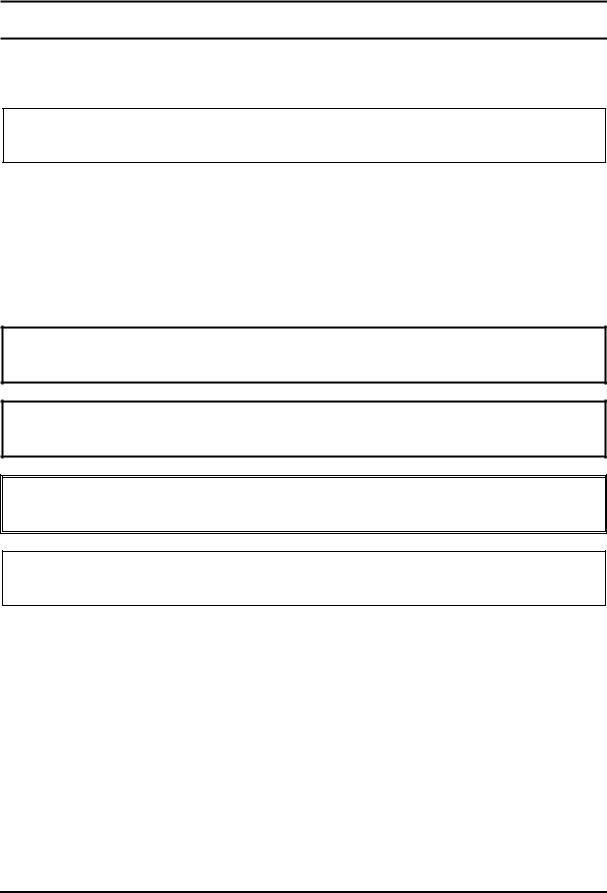
1.2System Block Diagram
Figure 1-2 shows the system block diagram.
Figure 1-2 System block diagram
QOSMIO G20 Maintenance Manual (960-511) |
[CONFIDENTIAL] |
1-5 |

1.2 System Block Diagram |
1 Hardware Overview |
The PC contains the following components.
CPU
Intel ® Mobile Pentium ®-M
Pentium-M 1.60GHz (Processor Number ; 730)
1.73GHz (Processor Number ; 740)
1.86GHz (Processor Number ; 750)
2.00GHz (Processor Number ; 760)
2.13GHz (Processor Number ; 770)
L1 cache : 64KB (32KB + 32KB)
L2 cache : 2MB
FSB : 533MHz Core voltage : 1.340~0.748V
Memory
Two memory slots capable of accepting DDR2-SDRAM 256MB, 512MB or 1024MB memory modules for a maximum of 2GB.
-200-pin small-size DIMM
-2.5V operation
-PC3200(DDR2-400)/PC4300(DDR2-533) support
BIOS ROM (Flash memory)
-8Mbit (512K×16-bit chip)
64KB used for logo/icon 224KB used for system BIOS 64KB used for VGA-BIOS 60KB used for Intel PXE 32KB used for ACPI
16KB used for MBI 17KB used for booting
16KB used for Parameter Block 19KB are reserved
1-6 |
[CONFIDENTIAL] |
QOSMIO G20 Maintenance Manual (960-511) |
1 Hardware Overview |
1.2 System Block Diagram |
Chipset
This gate array has the following elements and functions.
¾North Bridge (Intel 915PM <Express Chipset>)
-Support Dothan Processor System Bus
-System Memory Interface
-Memory Controller : DDR333/DDR2-400/DDR2-533, 2GB(max)
-Graphics I/F : x16 PCI Express Based Graphics I/F
-DMI (Direct Media Interface)
-1,257-ball 40.0mmx37.5mmx2.6mm FC-BGA Package
¾South Bridge (Intel 82801DBM (ICH6-M))
-DMI (Direct Media Interface)
-PCI Express I/F (4 ports)
-PCI Bus I/F Rev 2.3 (PCI REQ/GNT Pairs)
-Integrated Serial ATA Host Controller (2 ports, 150MB/S)
-Integrated IDE Controller (Ultra ATA 100/66/33)
-AC’97 2.3 codes
-USB 1.1/2.0 Controller 8 ports (EHCI: Enhanced Host Controller Interface)
-Built-in LAN Controller (Wfm 2.0& IEEE802.3 compliance)
-Power Management (ACPI 2.0 compliance)
-SMBus2.0 controller
-FWH interface (BIOS)
-LPC interface (EC/KBC, Super I/O)
-IRQ controller
-Serial Interrupt Function
-Suspend/Resume control
-Built-in RTC
-GPIO
-609-ball 31mmx31mm micro BGA Package
PC card controller (PCI7411, Texas Instrument-made)
-PCI Interface (PCI Rev. 2.3)
-PC Card Controller
-IEEE1394 Controller
-Flash Media Controller
-SD Host Controller
QOSMIO G20 Maintenance Manual (960-511) |
[CONFIDENTIAL] |
1-7 |

1.2 System Block Diagram |
1 Hardware Overview |
Super I/O (SMSC-made LPC47N217) Two serial ports (NS16C550 compatible)
-One port is used as Debug port
VGA controller nVIDIA NV43m
-Built-in VRAM 64MB/128MB
-PCI Express Interface
-LCD Interface LVDS 2ch
-Supports TV Encoder, S-Video
Mini PCI Wireless LAN card
2.4GHz DSSS/OFDM, 5.0GHz OFDM wireless LAN card is equipped. Conformity with IEEE 802.11b/g or IEEE 802a/b/g. Transfer speed is maximum of 11Mbit/sec. Supports 128bit WEP.
TV tuner
Some signals (NTSC, PAL and SECAM) are supported for worldwide use and MPEG2 hardware encoding function are also supported.
LAN controller (ICH4-M Kinnerth 82562EP)
Controls LAN and supports 100BASE-TX (Fast Ethernet)/10BASE-T (Ethernet).
Other main system chips
¾PSC (Toshiba-made TMP87PM48U x 1)
¾Clock Generator (ICS-made 954204BGFT x 1)
¾EC/KBC (Renesas-made M306KA x 1)
¾FWH (ST-Micro-made M50FW080N1 x 1)
¾AC97-CODEC (ADI-made AD1981 x 1)
¾Audio AMP (Matsushita-made AN12941A-VF x1)
¾SVP EX (Trident-made 7052-LF x 1)
1-8 |
[CONFIDENTIAL] |
QOSMIO G20 Maintenance Manual (960-511) |

1 Hardware Overview |
1.2 System Block Diagram |
MODEM (Askey-made 1456VQL4 x 1)
Supported by MDC.
Uses secondary AC97 line.
Data and FAX transmission is available. Supports ITU-TV.90.
The transfer speed of data receiving is 56kbps, of data sending is 33.6kbps and of FAX is 14.4kbps. Actual speed depends on the quality of the line used. Connected to telephone line through RJ11 MODEM jack.
QOSMIO G20 Maintenance Manual (960-511) |
[CONFIDENTIAL] |
1-9 |
1.3 2.5-inch Hard Disk Drive |
1 Hardware Overview |
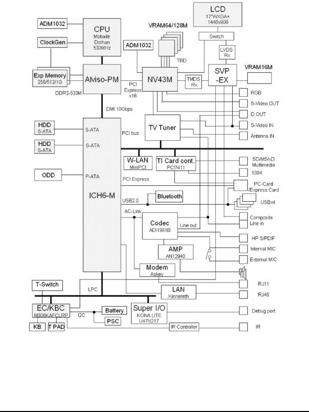
1.32.5-inch Hard Disk Drive
A compact, high-capacity Serial-ATA HDD with a height of 9.5mm. Contains a 2.5-inch magnetic disk and magnetic heads.
Figure 1-3 shows a view of the 2.5-inch HDD and Tables 1-1 and 1-2 list the specifications.
Figure 1-3 2.5-inch HDD
Table 1-1 2.5-inch HDD dimensions
Parameter |
|
|
Standard value |
|
|
|
|
FUJITSU |
|
FUJITSU |
TOSHIBA |
||||
|
|
G8BC0001R610 |
|
G8BC0001R810 |
HDD2D30BZK01 |
||
|
Width (mm) |
|
70.0 |
|
|
|
|
|
|
- |
|
||||
|
|
|
|
|
|
|
|
Outline |
Height (mm) |
|
9.5 |
|
|
|
|
|
- |
|
|||||
dimensions |
|
|
|
|
|
|
|
Depth (mm) |
|
100.0 |
|
|
|
||
|
- |
|
|||||
|
|
|
|
|
|||
|
Weight (g) |
99 (max) |
- |
|
|||
|
|
|
|
|
|
|
|
1-10 |
[CONFIDENTIAL] |
QOSMIO G20 Maintenance Manual (960-511) |

1 Hardware Overview |
|
|
|
1.3 2.5-inch Hard Disk Drive |
|||
|
|
Table 1-2 2.5-inch HDD Specifications |
|||||
|
|
|
|
|
|
|
|
|
|
|
|
|
Specification |
|
|
|
|
|
|
|
|
|
|
|
Parameter |
FUJITSU |
|
|
FUJITSU |
|
|
|
G8BC0001R610 |
|
G8BC0001R610 |
|
|||
|
|
|
|
|
|||
|
Storage size (formatted) |
60GB |
|
|
80GB |
|
|
|
|
|
|
|
|
|
|
|
Speed (RPM) |
|
|
|
5,400 |
|
|
|
Positioning |
Minimum |
|
|
1.5 ms |
|
|
|
time |
|
|
|
|
|
|
|
Average |
|
|
12 ms (read) |
|
||
|
|
|
|
|
|||
|
|
|
|
|
|
|
|
|
|
Maximum |
|
|
22 ms |
|
|
|
|
|
|
|
|
||
|
Data transfer |
To/From Media |
|
53.9 MB/s (max) |
|
||
|
speed |
|
|
|
|
|
|
|
To/From Host |
|
|
1.5GB/s (max) |
|
||
|
|
|
|
|
|||
|
|
|
|
|
|
|
|
|
Data Buffer size |
|
|
8MB |
|
||
|
|
|
|
|
|
||
|
Power-on-to-ready (sec) |
|
|
4 |
|
||
|
|
|
|
|
|
||
|
|
|
|
|
Specification |
|
|
|
|
|
|
|
|
|
|
|
Parameter |
|
|
TOSHIBA |
|
||
|
|
HDD2D30BZK01 |
|
||||
|
|
|
|
|
|||
|
Storage size (formatted) |
|
|
100GB |
|
||
|
Speed (RPM) |
|
|
|
5,400 |
|
|
|
|
|
|
|
|
|
|
|
Positioning |
Minimum |
|
|
- ms |
|
|
|
time |
|
|
|
|
|
|
|
Average |
|
|
- ms (read) |
|
||
|
|
|
|
|
|||
|
|
|
|
|
|
|
|
|
|
Maximum |
|
|
- ms |
|
|
|
|
|
|
|
|
|
|
|
Data transfer |
To/From Media |
|
|
- MB/s (max) |
|
|
|
speed |
|
|
|
|
|
|
|
To/From Host |
|
|
-GB/s (max) |
|
||
|
|
|
|
|
|||
|
|
|
|
|
|
|
|
|
Data Buffer size |
|
|
-MB |
|
||
|
|
|
|
|
|
||
|
Power-on-to-ready (sec) |
|
|
- |
|
||
|
|
|
|
|
|
|
|
QOSMIO G20 Maintenance Manual (960-511) |
[CONFIDENTIAL] |
1-11 |
1.4 Optical Drive |
1 Hardware Overview |
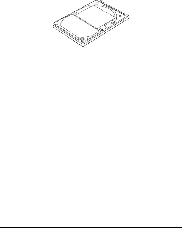
1.4Optical Drive
1.4.1 DVD Super Multi Drive (supporting Double-Layer)
The DVD Super Multi drive (supporting Double Layer) accommodates 12 cm (4.72-inch) CD/DVD-ROM, CD-R/RW, DVD±R/±RW and DVD-RAM. It is a high-performance drive that reads DVD-ROM at maximum 8-speed and CD-ROM at maximum 24-speed. It writes CD-R at maximum 24-speed, CD-RW at maximum 10-speed, DVD±R at maximum 8-speed, DVD±RW at maximum 4-speed, DVD-RAM at maximum 5-speed and DVD+R (Double Layer) at maximum 2.4-speeed.
The DVD Super Multi drive is shown in Figure 1-6. The dimensions and specifications of the DVD Super Multi drive are described in Table 1-7, Table 1-8.
Figure 1-4 DVD Super Multi drive (Double-Layer)
Table 1-3 DVD Super Multi drive (Double-Layer) outline dimensions
|
Parameter |
Standard value |
|
|
|
|
|
|
|
Maker |
MATSUSHITA-KOTOBUKI |
|
|
(G8CC0002CZ10) |
|
Outline |
|
|
|
|
Width (mm) |
128 |
|
dimensions |
|
||
|
|
|
|
(excluding |
|
Height (mm) |
12.7 |
projections) |
|
|
|
|
Depth (mm) |
129.0 |
|
|
|
||
|
|
|
|
|
|
Mass (g) |
179 (±15) |
|
|
|
|
1-12 |
[CONFIDENTIAL] |
QOSMIO G20 Maintenance Manual (960-511) |

1 Hardware Overview |
1.4 Optical Drive |
|||
|
Table 1-4 DVD Super Multi drive (Double-Layer) specifications |
|||
|
|
|
|
|
|
Parameter |
Drive Specification |
|
|
|
|
|
||
|
MATSUSHITA-KOTOBUKI (G8CC0002CZ10) |
|
||
|
|
|
|
|
|
|
|
|
|
|
|
Read(KB/s) |
DVD-ROM MAX 8X CAV |
|
|
|
CD-ROM MAX 24X CAV |
|
|
|
|
|
|
|
|
|
|
|
|
|
|
|
CD-R 24x (Zone CLV) |
|
|
|
|
CD-RW 4X (CLV) |
|
|
|
|
High Speed CD-RW 10X (CLV) |
|
|
|
Write |
Ultra Speed CD-RW 10X (CLV) |
|
|
Data transfer |
DVD-R 8x (Zone CLV) |
|
|
|
speed |
(Maximum) |
DVD-RW 4x (Zone CLV) |
|
|
|
|
DVD+R 8x (Zone CLV) |
|
|
|
|
DVD+R Double Layer 2.4x (CLV) |
|
|
|
|
DVD+RW 4x (Zone CLV) |
|
|
|
|
DVD-RAM 5x (ZCLV) (4.7GB) |
|
|
|
ATAPI interface |
PIO mode 16.6 MB/s (PIO MODE4 supported) |
|
|
|
DMA mode 16.6 MB/s (Multi-word MODE2 supported) |
|
|
|
|
(MB/s) |
|
|
|
|
Ultra DMA mode 33.3 MB/s(Ultra DMA MODE2 supported) |
|
|
|
|
|
|
|
|
|
|
|
|
|
Access time |
CD-ROM |
150 (Random) |
|
|
(ms) |
DVD-ROM |
180 (Random) |
|
|
|
|
||
|
|
|
|
|
|
Buffer memory |
2MB |
|
|
|
|
|
|
|
|
|
CD |
CD-DA, CD-ROM, CD-ROM XA, |
|
|
Supported disk |
Photo CD, CD-Extra(CD+), CD-text |
|
|
|
|
|
|
|
|
format |
DVD |
DVD-R, DVD-RW (Ver1.1) |
|
|
|
DVD+R/+RW, DVD Video, |
|
|
|
|
|
DVD-RAM (2.6GB/4.7GB) |
|
QOSMIO G20 Maintenance Manual (960-511) |
[CONFIDENTIAL] |
1-13 |
1.5 Keyboard |
1 Hardware Overview |
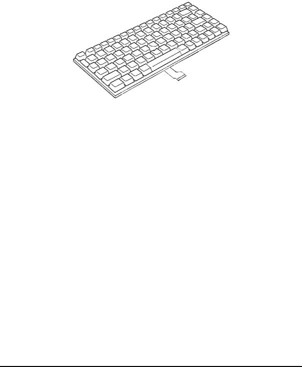
1.5Keyboard
A keyboard which consists of 85(US)/86(UK) keys is mounted on the system unit. The keyboard is connected to membrane connector on the system board and controlled by the keyboard controller.
Figure 1-7 is a view of the keyboard.
Figure 1-5 Keyboard
See Appendix E for details of the keyboard layout.
1-14 |
[CONFIDENTIAL] |
QOSMIO G20 Maintenance Manual (960-511) |
1 Hardware Overview |
1.6 TFT Color Display |
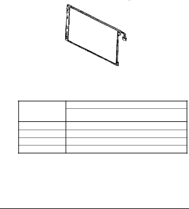
1.6TFT Color Display
The TFT color display is 17.1 inch and consists of LCD module and FL inverter board.
1.6.1 LCD Module
The LCD module used for the TFT color display uses a backlight as the light source and can display a maximum of 320,000 colors with 1,440 x 900 resolution.
Figure 1-8 shows a view of the LCD module and Table 1-9 lists the specifications.
Figure 1-6 LCD module
Table 1-5 LCD module specifications
Item
Number of Dots
Dot spacing (mm)
Display range (mm)
Outline dimensions
Specifications
LG-Philips (G33C0002K110)
1,440(W) × 900(H)
0.255 (H) x 0.255 (V)
367.2(W) x 229.5 (H)
382.2(w) x 246.8 (H) x 10.0(max) (D)
QOSMIO G20 Maintenance Manual (960-511) |
[CONFIDENTIAL] |
1-15 |

1.6 TFT Color Display |
1 Hardware Overview |
1.6.2 FL Inverter Board
The FL inverter board supplies a high frequency current to illuminate the LCD module FL. Table 1-10 lists the FL inverter board specifications.
Table 1-6 FL inverter board specifications
|
Item |
Specifications |
|
|
|
|
G71C0004F310 |
|
|
|
|
|
|
|
Input |
Voltage (V) |
5 (DC) |
|
|
|
|
Power (W) |
18 |
|
|
|
|
Voltage (V) |
900 (rms) |
|
|
|
Output |
Power (W/VA) |
7W / 10VA |
|
(x 2 output ; MAX 13W) |
|
|
|
|
|
Current |
7 (rms) |
|
(f=70KHz)(mA) |
(x 2 output) |
1-16 |
[CONFIDENTIAL] |
QOSMIO G20 Maintenance Manual (960-511) |
Loading...