

Toshiba Q9 True Torque Control2 Adjustable Speed Drive Quick Start Manual

Document Number: 59490-003
Date: April, 2010
Q9 ASD Quick Start Guide
Phone: 800.894.0412 - Fax: 888.723.4773 - Web: www.clrwtr.com - Email: info@clrwtr.com

Phone: 800.894.0412 - Fax: 888.723.4773 - Web: www.clrwtr.com - Email: info@clrwtr.com

Q9 ASD Quick Start Guide
Document Number: 59490-003
Date: April, 2010
Phone: 800.894.0412 - Fax: 888.723.4773 - Web: www.clrwtr.com - Email: info@clrwtr.com

Phone: 800.894.0412 - Fax: 888.723.4773 - Web: www.clrwtr.com - Email: info@clrwtr.com

Introduction
Phone: 800.894.0412 - Fax: 888.723.4773 - Web: www.clrwtr.com - Email: info@clrwtr.com
Congratulations on the purchase of the new Q9 True Tor que Control2 Adjustable Speed Drive!
The Q9 True Torque Control
True Torque Control
torque and provide compensation for motor slip, which results in smooth, quick starts and highly efficient
operation. The Q9 ASD uses digitally-controlled pulse width modulation. The programmable functions
may be accessed via the easy-to-use menu or via the Direct Access Numbers. These features, combined
with Toshiba’s high-performance software, delivers unparalleled motor control and reliability.
The Q9 ASD is a very powerful tool, yet surprisingly simple to operate. The user-friendly Electronic
Operator Interface (EOI) of the Q9 ASD has an easy-to-read LCD Screen. The EOI provides easy
access to the many monitoring and programming features of the Q9 ASD.
The motor control software is menu-driven, which allows for easy access to the motor control parameters
and quick changes when required.
To maximize the abilities of your new Q9 ASD, a working familiarity with this guide will be required.
This guide has been prepared for the ASD installer, user, and maintenance personnel. This guide may also
be used as a reference guide or for training. With this in mind, use this guide to develop a system
familiarity before attempting to install or operate the device.
For a more in-depth description of the many features of the Q9 ASD see the Q9 ASD Installation and
Operation Manual. The Q9 ASD Installation and Operation Manual may be downloaded from
Toshiba website or a
printed copy may be acquired from your Toshiba Sales Representative.
2
2
. Toshiba’s Vector Control Algorithm enables the motor to develop high starting
Adjustable Speed Drive (ASD) is a solid-state AC drive that features
Important Notice
The instructions contained in this guide are not intended to cover all details or variations in equipment
types, nor may it provide for every possible contingency concerning the installation, operation, or
maintenance of this equipment. Should additional information be required contact your Toshiba Sales
Representative.
The contents of this guide shall not become a part of or modify any prior or existing agreement,
commitment, or relationship. The sales contract contains the entire obligation of Toshiba International
Corporation. The warranty contained in the contract between the parties is the sole warranty of Toshiba
International Corporation and any statements contained herein do not create new warranties or modify the
existing warranty.
Any electrical or mechanical modifications to th is equipment without prior written consent of
Toshiba International Corporation may void all war ranties and may void the UL listing or other
safety certifications. Unauthorized modifications may also result in a safety hazard or equipment
damage.
Misuse of this equipment could result in injury and equipment damage. In no event will Toshiba
Corporation be responsible or liable for direct, indirect, special, or consequential damage or injury
that may result from the misuse of this equipment.

About This Guide
Phone: 800.894.0412 - Fax: 888.723.4773 - Web: www.clrwtr.com - Email: info@clrwtr.com
This guide was written by the Toshiba Technical Publications Group. This group is tasked with
providing technical documentation for the Q9 Adjustable Speed Drive. Every effort has been made to
provide accurate and concise information to you, our customer.
At Toshiba we’re continuously searching for b
our customers. E-mail your comments, questions, or concerns about this publication to Toshiba.
etter ways to meet the constantly changing needs of
Guide’s Purpose and Scope
This guide provides information on how to safely install, operate, maintain, and dispose of your
Q9Adjustable Speed Drive. The information provided in this guide is applicable to the
Q9 Adjustable Speed Drive only.
This guide provides information on the various features and functions of this powerful cost-saving
device, including
• Installation,
• System operation,
• Configuration and menu options, and
• Mechanical and electrical specifications.
Included is a section on general safety instructions that describe the warning labels and symbols that are
used throughout the guide. Read the guide completely before installing, operating, performing
maintenance, or disposing of this equipment.
This guide and the accompanying drawings should be considered a permanent part of the equipment
and should be readily available for reference and review. Dimensions shown in the guide are in metric
and/or the English equivalent.
Because of our commitment to continuous improvement, Toshiba International Corporation reserves
the right, without prior notice, to update information, make product changes, or to discontinue any
product or service identified in this publication.
Toshiba International Corporation (TIC) shall not be liable for direct, indirect, special, or
consequential damages resulting from the use of the information contained within this guide.
This guide is copyrighted. No part of this guide may be photocopied or reproduced in any form without
the prior written consent of Toshiba International Corporation.
© Copyright 2010 Toshiba International Corporation.
TOSHIBA® is a registered trademark of Toshiba Corporation. All other product or trade references
appearing in this guide are registered trademarks of their respective owners.
All rights reserved.
Printed in the U.S.A.

Contacting Toshiba’s Customer Support
TOSHIBA INTERNATIONAL CORPORATION
Q9 Adjustable Speed Drive
Please complete the Warranty Card supplied with the ASD and return it to Toshiba by prepaid mail. This will
activate the 12 month warranty from the date of installation; but, shall not exceed 18 months from the shipping
date.
Complete the following information and retain for your records.
Model Number: ______________________________________________________________________
Serial Number:_______________________________________________________________________
Project Number (if applicable):__________________________________________________________
Date of Installation:___________________________________________________________________
Inspected By:________________________________________________________________________
Name of Application:_________________________________________________________________
Phone: 800.894.0412 - Fax: 888.723.4773 - Web: www.clrwtr.com - Email: info@clrwtr.com
Center
Toshiba’s Customer Support Center can be contacted to obtain help in resolving any Adjustable Speed
Drive system problem that you may experience or to provide application information.
The Support Center is open from 8 a.m. to 5 p.m. (CST), Monday through Friday. The Center’s toll free
number is US (800) 231-1412/Fax (713) 937-9349 — Canada (800) 527-1204. For after-hours support
follow the directions in the outgoing message when calling.
You may also contact Toshiba by writing to:
Toshiba International Corporation
13131 West Little York Road
Houston, Texas 77041-9990
Attn: ASD Product Manager.
For further information on Toshiba’s products and services, please visit our web site.

Phone: 800.894.0412 - Fax: 888.723.4773 - Web: www.clrwtr.com - Email: info@clrwtr.com

Table of Contents
Phone: 800.894.0412 - Fax: 888.723.4773 - Web: www.clrwtr.com - Email: info@clrwtr.com
Gener a l Sa fe t y Inf o r ma t i on ....... ... .. .......... .. .......... .......... .. .......... .. .......... .. .......... ... ......... ........1
Safety Alert Symbol ........................................................................................................... 1
Signal Words ......................................................................................................................1
Special Symbols .................................................................................................................2
Equipment Warning Labels ................................................................................................2
Qualified Personnel ............................................................................................................2
Equipment Inspection ......................................................................................................... 3
Handling and Storage ......................................................................................................... 3
Disposal .............................................................................................................................. 3
Instal la t io n Precaut io ns ..... .. .. ... .......... ......... ... ......... ... .......... .. .......... .. .......... .......... .. ...............4
Location and Ambient Requirements ................................................................................. 4
Mounting Requirements .....................................................................................................4
Conductor Routing and Grounding ....................................................................................5
Power Connections .............................................................................................................6
Protection ............................................................................................................................ 6
System Integration Precautions ..............................................................................................7
Personnel Protection ...........................................................................................................7
System Setup Requirements ............................................................................................... 8
Operat i onal and Ma i nt en a nce Precautions ....... .. .. .......... ... ......... ... ......... ... .......... ......... ... .....9
Instal la t io n a n d Co n nection s ........ .. ... ......... ... ......... .......... ... ......... ... ......... ... .......... .. .......... ... 1 0
Installation Notes ..............................................................................................................10
Mounting the ASD ............................................................................................................11
Connecting the ASD .........................................................................................................12
Lead Length Specifications ..............................................................................................16
I/O and Control .................................................................................................................17
Electronic Operator Interface ..............................................................................................24
EOI Operation ...................................................................................................................24
EOI Remote Mounting .....................................................................................................24
EOI Features ..................................................................................................................... 25
System Configuration and Menu Options ...........................................................................27
Root Menu Items ..............................................................................................................27
System Operation ...................................................................................................................47
Operation (Local) ..............................................................................................................47
Default Setting Changes ...................................................................................................47
Enclosure Dimensions ............................................................................................................49
Enclosure Dimensions ...................................................................................................... 50
Current/Voltage Specifications .............................................................................................56
Cable/Terminal Specifications ..............................................................................................58
Short C ir cuit Protec t io n R ecommendation s ....... .. .......... ... ......... ... ......... ... .......... ......... ... ... 6 0
Q9 ASD Quick Start Guide i

ii Q9 ASD Quick Start Guide
Phone: 800.894.0412 - Fax: 888.723.4773 - Web: www.clrwtr.com - Email: info@clrwtr.com

General Safety Information
DANGER
WARNING
CAUTION
CAUTION
Phone: 800.894.0412 - Fax: 888.723.4773 - Web: www.clrwtr.com - Email: info@clrwtr.com
DO NOT attempt to install, operate, maintain, or dispose of this equipment until you have read and
understood all of the product safety information and directions that are contained in this guide.
Safety Alert Symbo l
The Safety Alert Symbol is comprised of an equilateral triangle enclosing an exclamation mark. This
indicates that a potential personal injury hazard exists.
Signal Words
Listed below are the signal words that are used throughout this guide followed by their descriptions and
associated symbols. When the words DANGER, WARNING, or CAUTION are used in this guide they
will be followed by important safety information that must be carefully followed.
The word DANGER preceded by the safety alert symbol indicates that an imminently hazardous
situation exists that, if not avoided, will result in serious injury to personnel or loss of life.
The word WARNING preceded by the safety alert symbol indicates that a potentially hazardous
situation exists that, if not avoided, could result in serious injury to personnel or loss of life.
The word CAUTION preceded by the safety alert symbol indicates that a potentially hazardous
situation exists that, if not avoided, may result in minor or moderate injury.
The word CAUTION without the safety alert symbol indicates a potentially hazardous situation exists
that, if not avoided, may result in equipment and property damage.
Q9 ASD Quick Start Guide 1

Sp ecial Symbols
Phone: 800.894.0412 - Fax: 888.723.4773 - Web: www.clrwtr.com - Email: info@clrwtr.com
To identify special hazards, other symbols may appear in conjunction with the DANGER, WARNING,
and CAUTION signal words. These symbols indicate areas that require special and/or strict adherence
to the procedures to prevent serious injury to personnel or loss of life.
Electrical Hazard Symbol
A symbol that is comprised of an equilateral triangle enclosing
a lightning bolt indicates a hazard of injury from electrical
shock or burn.
Explosion Hazard Symbol
A symbol that is comprised of an equilateral triangle enclosing
an explosion indicates a hazard of injury from exploding parts.
Equi pment Warning Labels
DO NOT attempt to install, operate, perform maintenance, or dispose of this equipment until you have
read and understood all of the product labels and user directions that are contained in this guide.
Warning labels that are attached to the equipment will include the exclamation mark within a triangle.
DO NOT remove or cover any of these labels. If the labels are damaged or if additional labels are
required, contact your Toshiba Sales Representative for additional labels.
Labels attached to the equipment are there to provide useful information or to indicate an imminently
hazardous situation that may result in serious injury, severe property and equipment damage, or loss of
life if safe procedures or methods are not followed as outlined in this guide.
Qualified Personnel
Installation, operation, and maintenance shall be performed by Qualified Personnel Only. A Qualified
Person is one that has the skills and knowledge relating to the construction, installation, operation, and
maintenance of the electrical equipment and has received safety training on the hazards involved (Refer
to the latest edition of NFPA 70E for additional safety requirements).
Qualified Personnel shall:
• Have carefully read the entire guide.
• Be familiar with the construction and function of the ASD, the equipment being driven, and the
hazards involved.
• Be able to recognize and properly address hazards associated with the application of motor-driven
equipment.
• Be trained and authorized to safely energize, de-energize, ground, lockout/tagout circuits and
equipment, and clear faults in accordance with established safety practices.
• Be trained in the proper care and use of protective equipment such as safety shoes, rubber gloves,
hard hats, safety glasses, face shields, flash clothing, etc., in accordance with established safety
practices.
For further information on workplace safety visit
2 Q9 ASD Quick Start Guide
osha website.

Equipment Inspection
Phone: 800.894.0412 - Fax: 888.723.4773 - Web: www.clrwtr.com - Email: info@clrwtr.com
• Upon receipt of the equipment inspect the packaging and equipment for shipping damage.
• Carefully unpack the equipment and check for parts that may have been damaged during shipping,
missing parts, or concealed damage. If any discrepancies are discovered, it should be noted with the
carrier prior to accepting the shipment, if possible. File a claim with the carrier if necessary and
immediately notify your Toshiba Sales Representative.
• DO NOT install the ASD if it is damaged or if it is missing any component(s).
• Ensure that the rated capacity and the model number specified on the nameplate conform to the
order specifications.
• Modification of this equipment is dangerous and is to be performed by factory trained personnel.
When modifications are required contact your Toshiba Sales Representative.
• Inspections may be required after moving equipment.
• Contact your Toshiba Sales Representative to report discrepancies or for assistance if required.
Handling and Storage
• Use proper lifting techniques when moving the ASD; including properly sizing up the load, getting
assistance, and using a forklift if required.
• Store in a well-ventilated location and preferably in the original carton if the equipment will not be
used upon receipt.
• Store in a cool, clean, and dry location. Avoid storage locations with extreme temperatures, rapid
temperature changes, high humidity, moisture, dust, corrosive gases, or metal particles.
• The storage temperature range of the Q9 ASD is -13° to 149° F (-25° to 65° C).
• DO NOT store the unit in places that are exposed to outside weather conditions (i.e., wind, rain,
snow, etc.).
• Store in an upright position.
Disposal
Never dispose of electrical components via incineration. Contact your state environmental agency for
details on disposal of electrical components and packaging in your area.
Q9 ASD Quick Start Guide 3

Inst a lla ti on Pre cautions
Phone: 800.894.0412 - Fax: 888.723.4773 - Web: www.clrwtr.com - Email: info@clrwtr.com
Location and Ambient Requirements
• The Toshiba Q9 ASD is intended for permanent installations only.
• Installation should conform to the 2008 National Electrical Code — Article 110 (NEC)
(Requirements For Electric al I n stallations), all regulations of the Occupational Safety and
Health Administration, and any other applicable national, regional, or industry codes and
standards.
• Select a mounting location that is easily accessible, has adequate personnel working space, and
adequate illumination for adjustment, inspection, and maintenance of the equipment (refer to 2008
NEC Article 110-13).
• DO NOT mount the ASD in a location that would produce catastrophic results if it were to fall
from its mounting location (equipment damage or injury).
• DO NOT mount the ASD in a location that would allow it to be exposed to flammable chemicals or
gases, water, solvents, or other fluids.
• Avoid installation in areas where vibration, heat, humidity, dust, fibers, metal particles, explosive/
corrosive mists or gases, or sources of electrical noise are present.
• The installation location shall not be exposed to direct sunlight.
• DO NOT obstruct the ventilation openings. Allow proper clearance spaces for installation. Refer to
the section titled Mounting the ASD on pg. 11 for further information on ventilation requirements.
• The ambient operating temperature range of the Q9 ASD is 14° to 104° F (-10° to 40° C).
Mounting Re qui reme nts
• Only Qualified Personnel are to install this equipment.
• Install the unit in a secure and upright position in a well-ventilated area.
• As a minimum, the installation of the equipment should conform to the 2008 National Ele ctrical
Code — Article 110 (NEC), OSHA, as well as any other applicable national, regional, or industry
codes and standards.
• Installation practices shall conform to the latest revision of NFPA 70E Electrical Safety
Requirements for Employee Workplaces.
• It is the responsibility of the ASD installer/maintenance personnel to ensure that the unit is installed
into an enclosure that will protect personnel against electric shock.
4 Q9 ASD Quick Start Guide

Cond uctor Routing and Groundi ng
WARNING
Phone: 800.894.0412 - Fax: 888.723.4773 - Web: www.clrwtr.com - Email: info@clrwtr.com
• Use separate metal conduits for routing the input power, output power, and control circuits.
• A separate ground cable should be run inside of the conduit with the input power, output power,
and control circuits.
• DO NOT connect CC to earth ground.
•Use IICC terminal as the return for the VI/II (V/I) input.
• Always ground the ASD to prevent electrical shock and to help reduce electrical noise.
• It is the responsibility of the person installing the ASD or the electrical maintenance personnel to
provide proper grounding and branch circuit protection in accordance with the 2008 NEC and any
applicable local codes.
— The Metal Of Conduit Is Not An Acceptable Ground —
Grounding Capacit or Switch
The ASD is equipped with leak reduction capacitors which are used to reduce the EMI leakage via the
3-phase power-input circuit and for compliance with the Electromagnetic Compatibility Directive
(EMC).
The effective value of the capacitor may be increased, reduced, or removed entirely via the Selector
Switch, Switching Bar, or the Switching Screw — the type used is typeform-specific.
The Grounding Capacitor Switch allows the user to quickly change the value of the leakage-reduction
capacitance of the 3-phase input circuit without the use of any tools.
See the section titled Power Connection Requirements on pg. 13 for more on the Grounding Capacitor.
See figures 4, 5, 6, and Figure 7 on pg. 15 for an electrical depiction of the leakage-reduction
functionality of the Grounding Capacitor and the methods used to set the capacitance value.
Q9 ASD Quick Start Guide 5

Power Connections
DANGER
Phone: 800.894.0412 - Fax: 888.723.4773 - Web: www.clrwtr.com - Email: info@clrwtr.com
Contact With Energized Wiring Will Cause Severe
Injury Or Loss Of Life.
• Turn off, lockout, and tag out all power sources before proceeding to connect the power wiring to
the equipment.
• After ensuring that all power sources are turned off and isolated in accordance with established
lockout/tag out procedures, connect 3-phase power source wiring of the correct voltage to the
correct input terminals and connect the output terminals to a motor of the correct voltage and type
for the application (refer to NEC Article 300 – Wiring Methods and Article 310 – Conductors For
General Wiring). Size the branch circuit conductors in accordance with NEC Table 310.16.
• If multiple conductors are used in parallel for the input or output power and it is necessary to use
separate conduits, each parallel set shall have its own conduit (i.e., place U1, V1, W1, and a ground
wire in one conduit and U2, V2, W2 and a ground wire in another) (refer to NEC Article 300.20
and Article 310.4). National and local electrical codes should be referenced if three or more power
conductors are run in the same conduit (refer to 2008 NEC Article 310 adjustment factors).
• Ensure that the 3-phase input power is NOT connected to the output of the ASD. This will damage
the ASD and may cause injury to personnel.
• DO NOT connect resistors across terminals PA – PC or PO – PC. This may cause a fire.
• Ensure the correct phase sequence and the desired direction of motor rotation in the Bypass mode
(if applicable).
• Turn the power on only after attaching and/or securing the front cover.
Protection
• Ensure that primary protection exists for the input wiring to the equipment. This protection must be
able to interrupt the available fault current from the power line. The equipment may or may not be
equipped with an input disconnect (option).
• All cable entry openings must be sealed to reduce the risk of entry by vermin and to allow for
maximum cooling efficiency.
• Follow all warnings and precautions and do not exceed equipment ratings.
• External dynamic braking resistors must be thermally protected. See the Q9 Adjustable Speed
Drive Instal lation and Operation Manual for further information on the requirements of the
Dynamic Braking setup and use.
• It is the responsibility of the ASD installer/maintenance personnel to setup the Emergency Off
braking system of the ASD. The function of the Emergency Off braking function is to remove
output power from the ASD in the event of an emergency. A supplemental braking system may also
be engaged in the event of an emergency. For further information on braking systems, see
parameters F250 and F304.
Note: A supplemental emergency stopping system should be used with the ASD.
Emergency stopping should not be a task of the ASD alone.
6 Q9 ASD Quick Start Guide
System Integration Precautions
WARNING
Phone: 800.894.0412 - Fax: 888.723.4773 - Web: www.clrwtr.com - Email: info@clrwtr.com
The following precautions are provided as general guidelines for the setup of the ASD within the
system.
• The Toshiba ASD is a general-purpose product. It is a system component only and the system
design should take this into consideration. Please contact your Toshiba Sales Representative for
application-specific information or for training support.
• The Toshiba ASD is part of a larger system and the safe operation of the ASD will depend upon
observing certain precautions and performing proper system integration.
• Improperly designed or improperly installed system interlocks may render the motor unable to start
or stop on command.
• The failure of external or ancillary components may cause intermittent system operation (i.e., the
system may start the motor without warning).
• A detailed system analysis and job safety analysis should be performed by the systems designer
and/or systems integrator before the installation of the ASD component. Contact your Toshiba
Sales Representative for options availability and for application-specific system integration
information if required.
Personnel Protect ion
• Installation, operation, and maintenance shall be performed by Qualified Personnel Only.
• A thorough understanding of the ASD will be required before the installation, operation, or
maintenance of the ASD.
• Rotating machinery and live conductors can be hazardous and shall not come into contact with
personnel. Personnel should be protected from all rotating machinery and electrical hazards at all
times.
• Insulators, machine guards, and electrical safeguards may fail or be defeated by the purposeful or
inadvertent actions of workers. Insulators, machine guards, and electrical safeguards are to be
inspected (and tested where possible) at installation and periodically after installation for potential
hazardous conditions.
• DO NOT allow personnel near rotating machinery. Warning signs to this effect shall be posted at
or near the machinery.
• DO NOT allow personnel near electrical conductors. Contact with electrical conductors can be
fatal. Warning signs to this effect shall be posted at or near the hazard.
• Personal protection equipment shall be provided and used to protect employees from any hazards
inherent to system operation.
Q9 ASD Quick Start Guide 7

System Setup Requirements
CAUTION
Phone: 800.894.0412 - Fax: 888.723.4773 - Web: www.clrwtr.com - Email: info@clrwtr.com
• When using the ASD as an integral part of a larger system, it is the responsibility of the ASD
installer/maintenance personnel to ensure that there is a fail-safe in place (i.e., an arrangement
designed to switch the system to a safe condition if there is a fault or failure).
• System safety features should be employed and designed into the integrated system in a manner
such that system operation, even in the event of system failure, will not cause harm or result in
system damage or injury to personnel (i.e., E-Off, Auto-Restart settings, System Interlocks, etc.).
• The programming setup and system configuration of the ASD may allow it to start the motor
unexpectedly. A familiarity with the Auto-Restart settings are a requirement to use this product.
• There may be thermal or physical properties, or ancillary devices integrated into the overall system
that may allow for the ASD to start the motor without warning. Signs must be posted to this effect
at the equipment installation location.
• DO NOT install power factor improvement capacitors or surge absorbers on the output of the ASD.
• Use of the built-in system protective features is highly recommended (i.e., E-Off, Overload
Protection, etc.).
• The operating controls and system status indicators should be clearly readable and positioned
where the operator can see them without obstruction.
• Additional warnings and notifications shall be posted at the equipment installation location as
deemed required by Qualified Personnel.
• Follow all warnings and precautions and do not exceed equipment ratings.
•The Dynamic Braking function is not used with the Q9 ASD.
• DO NOT attempt to configure or connect the DBR function to the Q9 ASD.
• Attempts to configure or adapt the ASD to use the Dynamic Braking function may result in system
damage or injury to personnel.
• If a secondary magnetic contactor (MC) or an ASD output disconnect is used between the ASD and
the load, it should be interlocked to halt the ASD before the secondary contact opens. If the output
contactor is used for bypass operation, it must be interlocked such that commercial power is never
applied to the ASD output terminals (U, V, or W).
• When using an ASD output disconnect the ASD and the motor must be stopped before the
disconnect is either opened or closed. Closing the output disconnect while the 3-phase output of the
ASD is active may result in equipment damage or injury to personnel.
8 Q9 ASD Quick Start Guide

Operational and Maintenance
WARNING
Phone: 800.894.0412 - Fax: 888.723.4773 - Web: www.clrwtr.com - Email: info@clrwtr.com
Precautions
• Turn off, lockout, and tag out the main power, the control power, and instrumentation connections
before inspecting or servicing the ASD, connecting or disconnecting the power wiring to the
equipment, or opening the door of the enclosure.
• The capacitors of the ASD maintain a residual charge for a period of time after turning the ASD off.
The required time for each ASD typeform is indicated with a cabinet label and a Charge LED
(Shown for smaller ASD in Figure 2 on pg. 12; is located on the front panel of larger ASDs). Wait
for at least the minimum time indicated on the enclosure-mounted label and ensure that the Charge
LED has gone out before opening the door of the ASD once the ASD power has been turned off.
• Turn the power on only after attaching (or closing) the front cover and DO NO T remove or open
the front cover of the ASD when the power is on.
• DO NOT attempt to disassemble, modify, or repair the ASD. Call your Toshiba Sales
Representative for repair information.
• DO NOT place any objects inside of the ASD.
• If the ASD should emit smoke, or an unusual odor or sound, turn the power off immediately.
• The heat sink and other components may become extremely hot to the touch. Allow the unit to cool
before coming in contact with these items.
• Remove power from the ASD during extended periods of non-use.
• The system should be inspected periodically for damaged or improperly functioning parts,
cleanliness, and to ensure that the connectors are tightened securely.
Q9 ASD Quick Start Guide 9

Installation and Connections
CAUTION
Phone: 800.894.0412 - Fax: 888.723.4773 - Web: www.clrwtr.com - Email: info@clrwtr.com
The ASD may be set up initially by performing a few simple configuration settings. To operate
properly, the ASD must be securely mounted and connected to a power source (3-phase AC input at the
R/L1, S/L2, and T/L3 terminals). The control terminals of the ASD may be used by connecting the
terminals of the Terminal Board (P/N 072314P903) to the proper sensors or signal input sources (See
the section titled I/O and Control on pg. 17
System performance may be further enhanced by assigning a function to the output terminals of the
Terminal Board and connecting the terminals to the proper indicators or actuators (LEDs, relays,
contactors, etc.).
Note: The option al Q9 ASD interface boards may be used to expand the I/O functionality of
the ASD.
Installation Notes
When a brake-equipped motor is connected to the ASD, it is possible that the brake may not release at
startup because of insufficient voltage. To avoid this, DO NOT connect the brake or the brake contactor
to the output of the ASD.
If an output contactor is used for bypass operation, it must be interlocked such that commercial power is
never applied to the output terminals of the ASD (U/T1, V/T2, and W/T3).
and
Figure 9 on pg. 20).
DO NOT apply commercial power to the ASD output terminals U/T 1, V/T2, and W/T3.
If a secondary magnetic contactor (MC) is used between the output of the ASD and the motor, it should
be interlocked such that the ST – CC connection is disconnected before the output contactor is opened.
DO NOT open and then close a secondary magnetic contactor between the ASD and the motor unless
the ASD is off and the motor is not rotating.
Note: Re-applicat ion of power via a secondary contact while the Q9 ASD is on or while the
motor is s t il l turnin g m a y cause ASD damage .
The Q9 ASD input voltage should remain within 10% of the specified input voltage range. Input
voltages approaching the upper or lower-limit settings may require that the over-voltage and undervoltage stall protection level parameters be adjusted. Voltages outside of the permissible tolerance
should be avoided.
The frequency of the input power should be ±2 Hz of the specified input frequency.
DO NOT use an ASD with a motor that has a power rating higher than the rated output of the ASD.
The Q9 ASD is designed to operate NEMA B motors. Consult with your Toshiba Sales Representative
before using the ASD for special applications such as with an explosion-proof motor or applications
with a piston load.
Disconnect the ASD from the motor before megging or applying a bypass voltage to the motor.
Interface problems may occur when an ASD is used in conjunction with some types of process
controllers. Signal isolation may be required to prevent controller and/or ASD malfunction (Contact
your Toshiba Sales Representative or the process controller manufacturer for additional information
about compatibility and signal isolation).
Use caution when setting the output frequency. Over-speeding a motor decreases the ability to deliver
torque and may result in damage to the motor and/or the driven equipment.
10 Q9 ASD Quick Start Guide
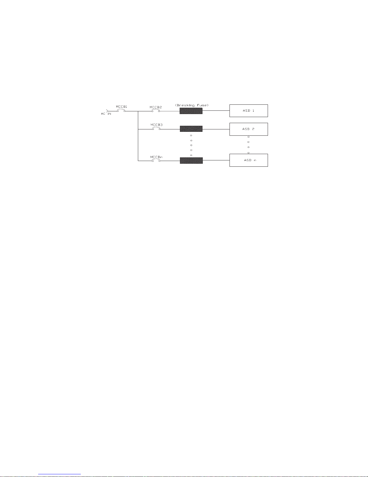
Not all ASDs are equipped with internal primary power input fuses (HP dependent). When connecting
Figure 1. Typical Circuit Breaker Configuration.
CAUTION
Phone: 800.894.0412 - Fax: 888.723.4773 - Web: www.clrwtr.com - Email: info@clrwtr.com
two or more drives that have no internal fuse to the same power line as shown in Figure 1, it will be
necessary to select a circuit-breaking configuration that will ensure that if a short circuit occurs in ASD
1, only MCCB2 trips, not MCCB1. If it is not feasible to use this configuration, insert a fuse between
MCCB2 and ASD 1.
Mounting the ASD
— The following thermal specifications apply to the 230- and 460-volt ASDs ONLY —
Install the unit securely in a well ventilated area that is out of direct sunlight.
The process of converting AC to DC, and then back to AC produces heat. During normal ASD
operation, up to 5% of the input energy to the ASD may be dissipated as heat. If installing the ASD in a
cabinet, ensure that there is adequate ventilation.
DO NOT operate the ASD with the enclosure door open.
The ambient operating temperature rating of the Q9 ASD is 14° to 104° F (-10° to 40° C).
When installing adjacent ASDs horizontally Toshiba recommends at least 5 cm of space between
adjacent units. However, horizontally mounted ASDs may be installed side-by-side with no space in
between the adjacent units — side-by-side installations require that the top cover be removed from each
ASD.
For 150 HP ASDs and above, a minimum of 50 cm of space is required above and below adjacent units
and any obstruction. This space is the recommended minimum space requirement for the ASD and
ensures that adequate ventilation is provided for each unit. More space will provide a better
environment for cooling (See the section titled Enclosure Dimensions on pg. 49 for additional
information on mounting space requirements).
Note: Ensure that the ventilation openings are not obstructed.
Q9 ASD Quick Start Guide 11
Connecting the ASD
DANGER
DANGER
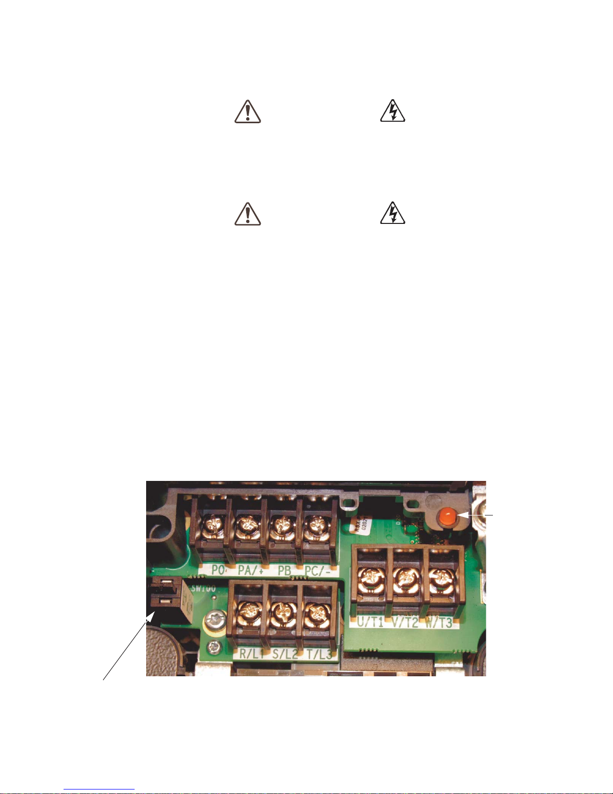
Grounding Capacitor Switch — Pull for Small capacitance/push for Large capacitance.
Note: PO-to-PA/+ shor ting bar removed to show re ference designators.
Charge
LED
Phone: 800.894.0412 - Fax: 888.723.4773 - Web: www.clrwtr.com - Email: info@clrwtr.com
Refer to the section titled Installation Precautions on pg. 4 and the section titled Lead Length
Specifications on pg. 16 before connecting the ASD and the motor to electrical power.
Power Connections
Contact With 3-Phase Input/Output Terminals May Cause
Electrical Shock Resulting In Injury Or Loss Of Life.
See Figure 20 on pg. 22 for a system I/O connectivity schematic.
An inductor (DCL) may be connected across the PO and PA/+ terminals to provide additional filtering.
When not used, a jumper must be connected across these terminals (See Figure 20 on pg. 22).
PA/+ and PB are used for the DBR connection. The DBR function is not used on the Q9 ASD.
PC/- is the negative terminal of the DC bus.
R/L1, S/L2, and T/L3 are the 3-phase input supply terminals for the ASD.
U/T1, V/T2, and W/T3 are the output terminals of the ASD that connect to the motor.
The location of the Charge LED for the smaller typeform ASD is provided in Figure 2. The Charge
LED is located on the front door of the enclosure of the larger ASDs.
Figure 2. Typical Q9 ASD input/output terminals and the Grounding Capacitor Switch.
12 Q9 ASD Quick Start Guide
 Loading...