

Page 1
Page 2
The PERCEPTION electronic business communications system is registered in accordance
with the provisions of Part 68 of the Federal
Communications Commission’s Rules
Regulations.
The Federal Communications Commission
(FCC) has established rules which permit the
PERCEPTION electronic business communications
system to be connected directly to the telephone
network. Connection points are provided by the
telephone company-connections for this type of
customer-provided equipment will not be pro-
vided on party lines or coin lines.
and
Before connecting a PERCEPTION system to
the telephone network, the telephone company
must be provided with the following:
A. Your telephone number
. The FCC registration number
7~443-~F-~)
C.
The ringer equivalence number
4.O(DC)
D. The USOC jack required
items B and C are also indicated on the equipment
label.
You must notify the telephone company upon
final disconnection of your equipment.
(RJ21X)
(BF287N-
1.2B(AC)/
If a PERCEPTION system is malfunctioning,
it may also be disrupting the telephone network.
The system should be disconnected until the
problem can be determined and repaired. If this
is not done, the telephone company may tem-
porarily disconnect service.
atibi
The telephone company may make changes
in its technical operations and procedures. If
such changes affect the compatibility or use of
a PERCEPTION system, the telephone company
is required to give adequate notice of the changes.
Warning: -This equipment generates, uses, and
can radiate radio frequency energy and if not
installed and used in accordance with the instructions manual, may cause interference to radio
communications. It has been tested and found
to comply with the limits for a Class A computing
device pursuant to Subpart J of Part 15 of FCC
Rules, which are designed to provide reasonable
protection against such interference when operated
in a commercial environment. Operation of this
equipment in a residential area is likely to cause
interference; in which case, the users, at his own
expense, will be required to take whatever measures
may be required to correct the interference.
Page 3
Toshiba Telecom reserves the right, without prior notice, to revise this information
publication for any reason, including, but not limited to, utilization of new advances in
the state of technical arts or to simply change the design of this document,
Further, Toshiba Telecom also reserves the right, without prior notice, to make such
changes in equipment design or components as engineering or manufacturing methods may
warrant.
All rights reserved. No part of this manual, covered by the copyrights hereon, with
the exception of the Programming Record Forms, may be reproduced in any form or by
any means-graphic, electronic, or mechanical, including recording, taping, photocopy,
or information retrieval systems-without express written permission of the publisher
of this material.
In the event of equipment malfunction, all repairs will be performed by Toshiba
America, Inc., Toshiba Telecom, or an authorized agent of Toshiba America, Inc.,
Toshiba Telecom.
Page 4

Page 5
SUBJECT
PAGE
01
TABLE OF CONTENTS.
GENERAL ..............................................
Summary Description. ..................................
Physical Descriptions. ...................................
ReservePower
AttendantConsole
Electronic Key Telephone.
Electrical Characteristics.
TABLE A (Electrical Characteristics) ..........................
Features and Services
TABLE B (Standard Features)
TABLE C (Optional Features). ...............................
SYSTEM OPERATION
General ..............................................
SYSTEM CONFIGURATION
Central Equipment Cabinet.
Electronic Key Telephone.
AttendantConsole..
Power Failure/Emergency Transfer Unit
INSTALLATION 2% MAINTENANCE
FEATURE DESCRIPTION
Standard Features.
Optional Features.
.........................................
...................................
.....................................
...............................
................................
...................................
...............................
.....................................
................................
..............................
...............................
...................................
(DPTU)
..........................
..................................
.....................................
.....................................
..............
TITLE
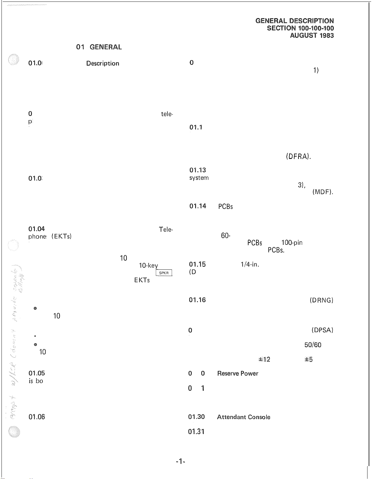
CABINET (Dimensions)
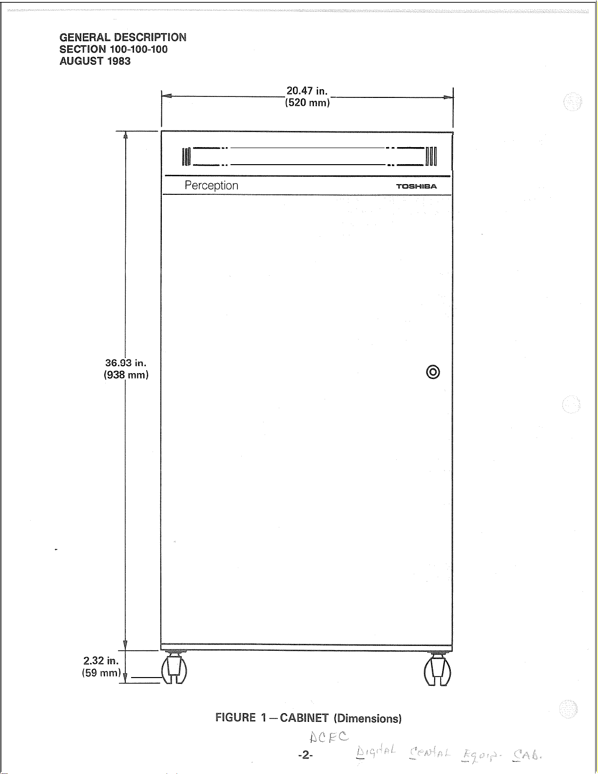
CABINET (Interior)
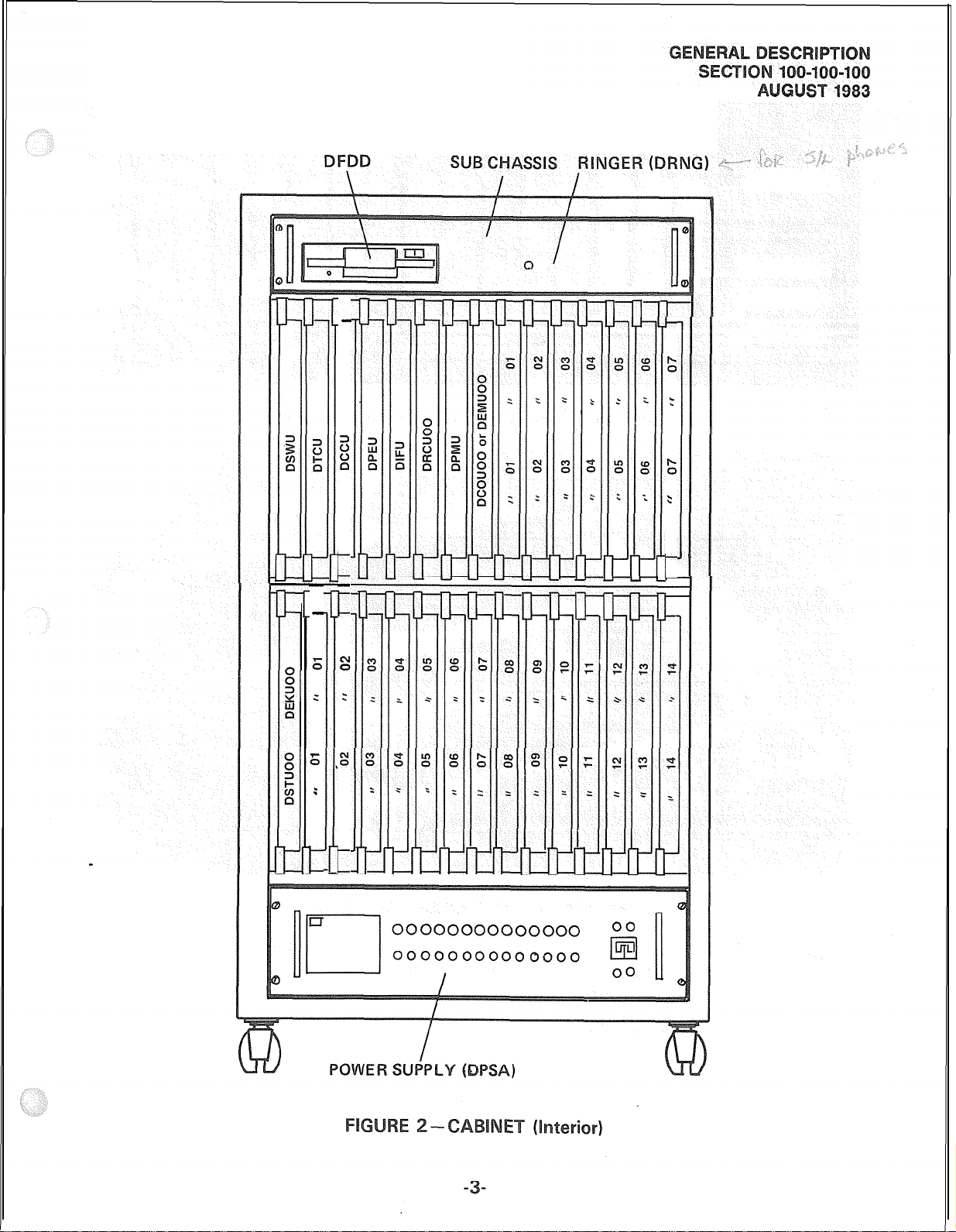
REAR CABINET CONNECTORS
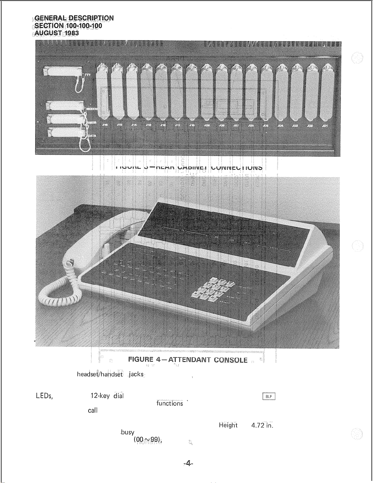
ATTENDANT CONSOLE
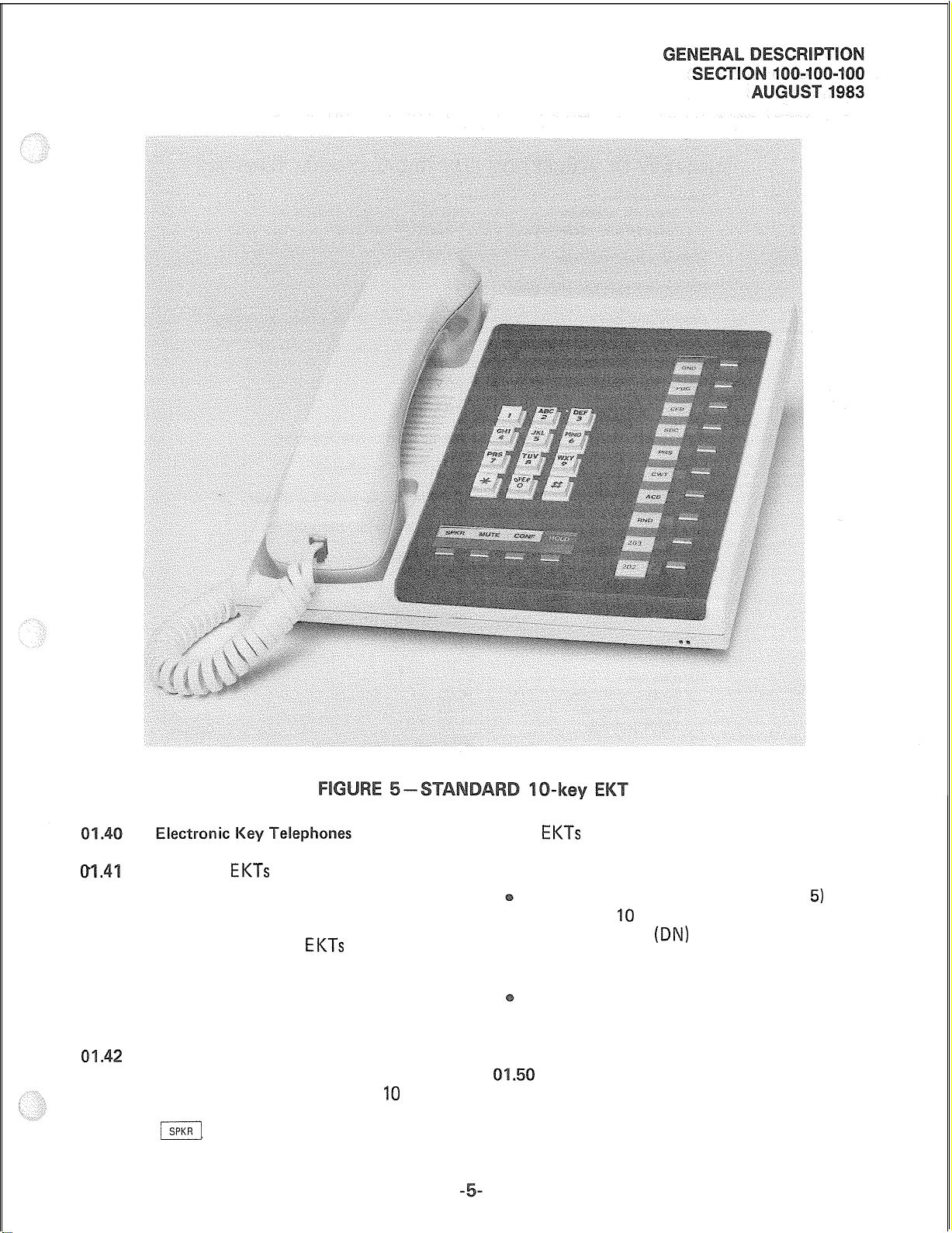
STANDARD IO-key EKT
SYSTEM DIAGRAM.
FUNCTIONAL BLOCK DIAGRAM
ATTENDANT CONS0 LE.
....................................
.......................................
...................................
...................................
......................................
..................................
.............................
...........................
Page 6
01.10
Physical Description
0
Summary
Dew-i
1.11
PERCEPTION equipment cabinet (Figure 1) are:
01.01 PERCEPTION is an advanced business
communication system, employing stored program
control, digital switching,
and custom LSI
circuitry.
1.02
Utilizing the same electronic key
tele-
It weighs 187.4 lb. (85 kg) when fully equipped.
hone as the new Toshiba STRATA electronic
key telephone systems (EKTS), PERCEPTION
combines the functions of conventional electronic
private branch exchange (EPABX) systems and
electronic key telephone systems into a single
design while remaining compatible with existing
into four shelves (Figure 2); two shelves for plug-in
printed circuit board (PCB) mounting, one shelf
for the power supply, and the top shelf contains
the Floppy Disk/Ringer Assembly
switching and station equipment.
3
PERCEPTION has a capacity of 120
stations and 32 trunks. The system provides a
wide variety of basic and optional features to
at the rear of the cabinet (Figure
minated on a main distribution frame
users of conventional rotary dial or touchtone
telephones, as well as to users of Electronic Key
Telephones.
high by 12.01 inches (305 mm) deep, and each
one has a metal faceplate riveted to the front
Two different Electronic Key
s
(EKTs)
are available with PERCEPTION.
Tele-
Each is equipped with a push-button dial pad,
speaker, four fixed feature keys (SPKR, MUTE,
edge. The rear edge connector carries the electrical
terminals:
pheral equipment
on the common equipment PCBs.
CONF and HOLD) and either 10 or 20 flexible
assignment keys (hence the names
20-key). Of the four fixed keys, only the
key is equipped with an LED. Both
IO-key
EKTs
and
j
feature
modular handset cords and are connected to the
.I5
FDD) stores system programs and customer
office data securely. The DFDD is mounted in
the left side of the DF RA subassembly.
system via four-conductor modular line cords.
The basic PERCEPTION EKT is a IO-key,
with 10 keys that may be assigned as directory
is mounted on the right side of the DFRA subassembly.
number (DN) pickups or as access keys to any
of the station custom calling features.
-
The expanded 20-key EKT has an additional
10
flexible assignment keys that may be
assigned as DN pickups or feature access keys.
1.17 The primary power supply
IS mounted in the bottom of the equipment
cabinet. It is operated by 115 VAC,
commercial power and provides a fused output
of -48 VDC, -24 VDC,
The physical parameters of the metal
Height
Width
Depth
2
The central equipment cabinet is divided
39.25 in. (997 mm)
20.47 in. (520 mm)
15.75 in. (400 mm)
(DFRA).
External connections are made to the
via amphenol-ended cables connected
3),
and ter-
(MDF).
PCBs
measure 12.01 inches (305 mm)
60-
and 40-pin terminals on the peri-
PCBs
and
The 5
l/4-in.
Floppy Disk Drive Unit
The 20 Hz ringing power supply
loo-pin
terminals
(DRNG)
(DPSA)
50/60
Hz
*I2
VDC and k5 VDC.
The PERCEPTION Attendant Console
th attractive and efficient. Its digital display
provides the operator with all the information
required for easy operation. Two attendant consoles may be equipped in the system.
Housed in a single attractively styled
cabinet, the noiseless operation, small size and
environmental tolerance of the central equipment
allows a wide choice of installation locations.
1.2
1.2 A commercially-available Uninterruptible
Power Supply system is used to supply emergency
power.
1.3
The PERCEPTION Attendant Console
(Figure 4) is enclosed in an off-white plastic
Page 7
---
iI
---
---
-- -
llnll
Page 8
-
r
s
531
DFRA
I-
f;
:
6
:
c
-
-
-
L
r
E;
:
;
G
:
c
t
I-
Page 9
-
“,.’
‘_‘
housing with
headsei/hapdse$ .jacks,
located on _ “hundreds group” identifier that shows which
‘/’
both sides. It is equipped with a keyboard having of the two groups is currently being displayed.
two horizontal rows. of non-locking keys and The display alternates between groups in response
LEDs,
a standard
row of four keys. The ‘console display
include incoming
party), class of service, destination (called party)
and status (of called party). In addition, the
console is equipped with a
displays 100 2-digit numbers
la-key dial
pad and a vertical
functibns ”
carI
identification, source (calling
.busy
lamp field that
(OQ-w99),
and a
‘to operations of the
m
key (located on the
console keyboard). Trunk group busy display,
call waiting and alarm indications are also provided.
The Attendant Console measures:
Height 4.72-in.
(120 mm)
Width 14.17 in. (360 mm)
,,,
Depth 10.24 in. (260 mm)
Page 10
The two
PERCEPTION are housed in an off-white plastic
case
(brown, blue, black and wine). They are the same
units as the STRATA series
dial pad, speaker, four fixed feature keys (SPKR,
flexible assignment keys. Of the four fixed keys,
with interchangeable colored faceplates
Height
Width 8.8 in. (224 mm)
Depth 9.1 in. (230 mm)
Each is equipped with a push-button
MUTE, CONF and HOLD) and either IO or 20
only the
‘SPI(R]
EKTs
that are available with
EKTs
and measure:
4.0 in. (102 mm)
key is equipped with an LED.
Both
EKTs
feature modular handset cords and
are connected to the system via 4-conductor modular line cords.
The basic PERCEPTION EKT (Figure 5) is a
IO-key, with IO keys that may be assigned as
directory number
keys to any of the station custom calling
features.
The expanded 20-key EKT has an additional
10 flexible assignment keys that may be
assigned as DN pickups or feature access keys.
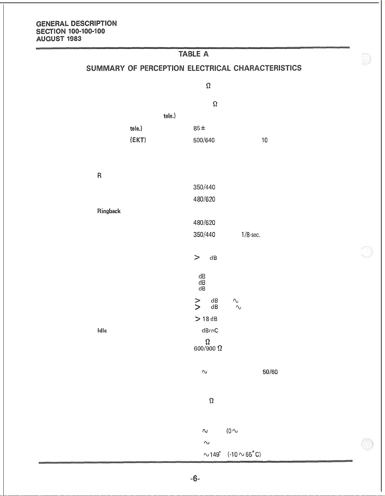
Electrical Characteristics
01.5’1
CEPTION are detailed in Table A.
The electrical characteristics of PER-
(DN)
pickups or as access
Page 11
Station loop limit
Standard telephone
Electronic key telephone
500
R
1000 ft. 24 AWG cable
(including telephone)
Minimum leak resistance
Maximum ringer/line (std.
Ringing (std.
Ringing tone
Buzz tone
Busy override tone
ing trip
Dial tone
Busy tone
Ringback
Overflow tone
Recall dial tone
Miscellaneous tones
Crosstalk
Insertion loss
Station-to-station
Station-to-trunk
Trunk-to-trunk
tele.)
(EKT)
tone
tele.)
30,000
3
85f
500/640
300 Hz
2400 Hz
During silent or ringing period
3501440
480/620
4401480 Hz, 1 sec. on, 3 sec. off
480/620
350/440
440 Hz
5
R
10 Vrms, 20 Hz, immediate ringing
Hz, modulated at IO Hz
Hz, continuous
Hz, interrupted at 60 ipm
Hz, interrupted at 120 ipm
Hz, three
>
75 dB down
dB
1
dB
1
dB
l/8-sec.
pulses, followed by continuous tone
Longitudinal balance
Return loss
idle
circuit noise
System impedance
Switching
Primary power
Reserve power
Central office loop limit
Maximum distance between
console and equipment cabinet
Operating temperature
Operating humidity
Storage temperature
>
60 dB (200 h 1000 Hz) on- and off-hook
>
40 dB (1000 ‘L 4000 Hz) on- and off-hook
> 18dB
25
600
600/900 5-2
TDM, PCM, non-blocking
905125 VAC, 500
An external charger/inverter supplies 115 VAC to the primary
power supply
1500
1000 ft. (24 AWG)
32 m 104” F (0 ti 40” C)
20
14
ERL
dBrnC
Q
for stations
for trunks
watts,
r;2
I\J
80% without condensation
I‘v149’
F
(-10~65°C)
50160
Hz
Page 12
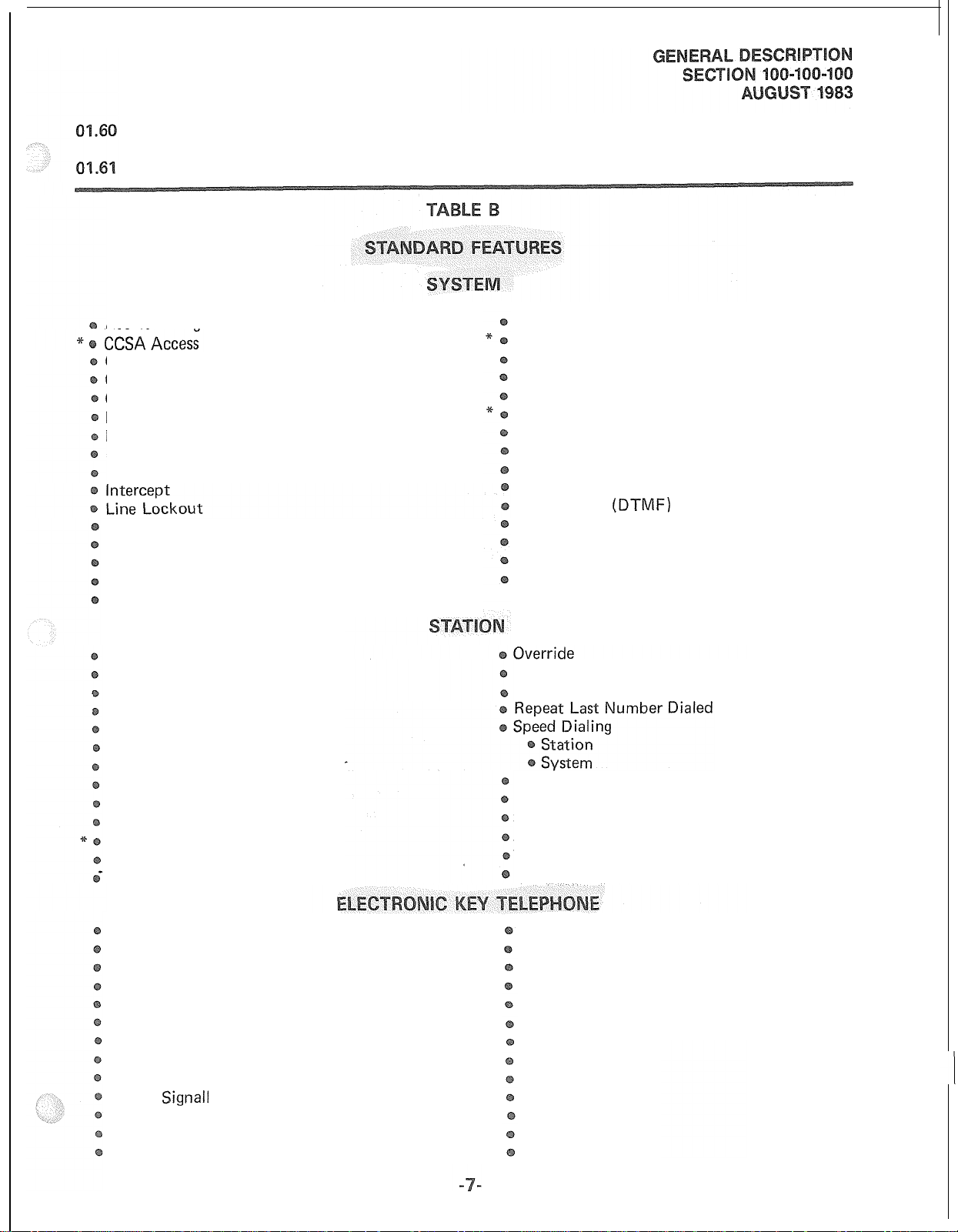
Features and Services
All the features and services available
in PERCEPTION are summarized in Tables B and
C, which list the basic and optional features,
respectively.
Access to Paging
Class of Service Restrictions
Code Restrictions-3-digit
Console-less Operation
Data Transmission-voice band
Distinctive Ringing
Flexible Numbering
Immediate Ringing
Multiple Console Operation
Multiple Trunk Groups
Music-on-hold and Camp-on
Night Service-Fixed
Night Service-Flexible
Automatic Callback
Call Forward-All Calls
Call Forward-No Answer
Call Pickup-Directed
Call Pickup-Group
Call Waiting
Conference-3-party With Transfer
Direct Outward Dialing
Do Not Disturb
Hold-All Calls
Manual Line Service
Meet-me Page
Message Waiting
Night Service-Universal
Remote Access to Services
Remote Administration/Maintenance
Rotary Dial Compatibility
Route Advance
Station Set Mix
Tandem Switching
Tenant Service
Tie Trunks
Toll Restriciton
Tone Dialing
Tone-to-dial Pulse Conversion
Traffic Measurement
Uniform Distribution Wiring
Variable Time-out
Private CO Line Services
Remote Retrieval of Held Calls
Station Hunting-Circular
Station Hunting-Distributed
Station Hunting-Secretarial
Station Hunting-Terminal
Trunk-to-trunk Connections
Uninterrupted Line Connection
(DTMF)
Automatic Dialing
Automatic Line Preference
Call Status Indication
Common Audible Signalling
End-to-end Signalling
Handsfree Answerback with Speaker Cut-off
Handsfree Monitoring
l-hold Indication
I-use Indication
Manual
Modular Cords
Multiple Appearance Directory Number
Non-locking Keys
Signall
ing
On-hook Dialing
Prime Directory Number
Privacy
Privacy Release
Push-button Dialing
Push-button/key Access to Features
Release
Speaker/Amplifier
Speakerphone
Tone Buzzing
Tone Ringing
Voice Paging
Volume Control
*Future feature
Page 13
Attendant Camp-on with Indication
Attendant Conference
Attendant Emergency Transfer Control
Attendant Initialize
Attendant Recall
Busy Lamp Field
Call Waiting Lamp
Digital Information Display
Direct Access to Paging
Incoming Call lndentification
Individual Trunk Access
Night Service Control
Non-delayed Operation
Overflow Facility
Speed Dialing-System
Station Verification
Switched Loop Termination
Through Dialing
Timed Reminders-Variable
Time of Day Display, Set, Reset
Trunk Group Access Control
Trunk Group Busy Indication
Trunk Equipment Number Display
Trunk-to-trunk Connections
Trunk Verification
Power Failure/Emergency Transfer
ect Inward Dialing (DID)
Call Forward-Busy
Multiple Listed Directory Number
20-key EKT
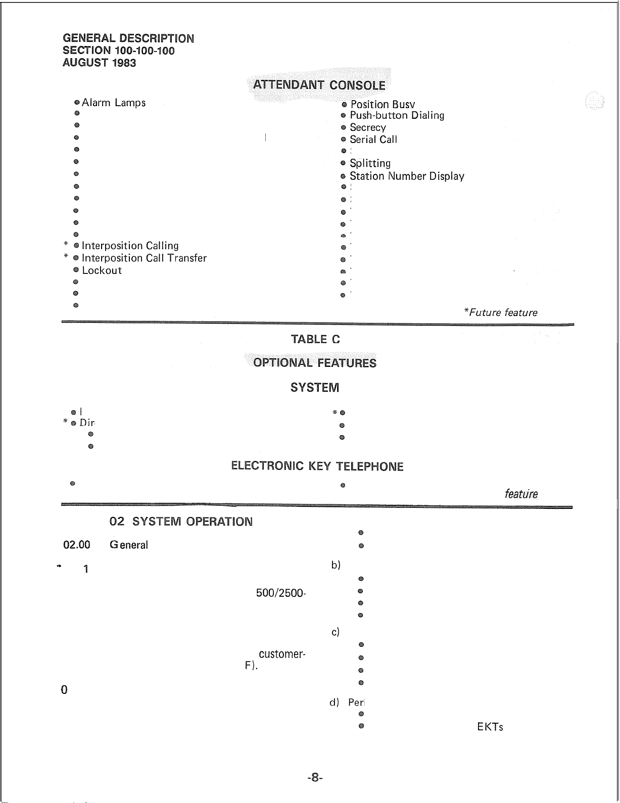
Q2.00
-
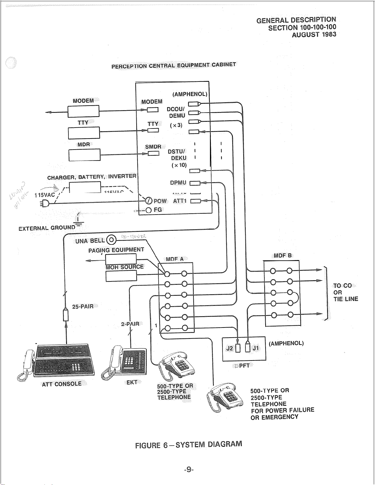
02.0 The system diagram in Figure 6 shows
the central equipment cabinet, attendant console,
electronic key telephone, conventional
type telephone,
An external customer-provided tuner (or equiva-
lent) is required as a music-on-hold source. All
connections to on-premise equipment and the
public telephone network are made via a
provided main distribution frame (MD
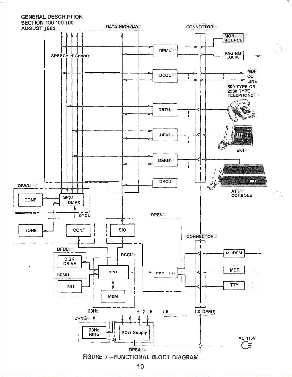
2.02 The functional block diagram in Figure 7
shows the central equipment divided into four
main sections; power, central control, central
service equipment and peripheral interface equipment.
eneral
500/2500-
and emergency transfer unit.
customer-
F).
Least Cost Routing
Station Message Detail Recording
Reserve Power
Wall Mount Kit
a) Power Section:
Main power supply
20 Hz ringing
b)
Central Control:
Floppy disk unit
DCCU
DPEU
A portion of DPMU
c)
Central Service Equipment:
DTCU
DSWU
DRCU
A portion of DPMU
ipheral Interface Equipment:
DSTU (interfaces conventional telephones)
DEKU (interfaces the
consoles)
“Future
EKTs
featuke
and attendant
Page 14
1
______ -----
Page 15
--1
--I-
---
r
--
-----7---1
20Hz
r----
-48 -24
.--
--l
+12 +5
PE
-65
1
--
(ONLY DCCU
Page 16
Various trunk interfaces, such as:
DCOU (CO trunk)
DEMU (tie trunk)
Central Control Unit
central processing unit and system memory;
performs all system control functions.
(DCCU)-contains
the
2.03 PERCEPTION utilizes a non-blocking,
pulse code modulated (PCM), time division net-
work consisting of six
and a multiplexer circuit that performs time slot
interchange, digital padding, and conferencing
functions. Analog-to-digital conversion is per-
formed on each peripheral PCB. System tones
(dial, busy, etc) are stored in digital form in
read-only-memory (ROM).
Central control consists primarily of a
processor and its associated memory. Hard-
ware logic necessary for various system interfaces
is located on the DPEU PCB; a floppy disk unit
is used for secure memory storage.
0
0
mounting shelves, power supply, ringing supply,
and floppy disk unit in the central equipment
cabinet (DCEC). All
of the cabinet; all external connections are made
at the rear of the cabinet (Figure 3).
entral E
Figure 2 shows the location of the PCB
32-time-slot
PCBs
PCM highways
plug in from the front
Peripheral Unit
mission and receiving functions between
station and trunk interfaces and the central
control.
Receiver Unit
ceivers, which are required for receiving dialing
from 2500 telephones. Two types of DRCU
PCBs
are available: DRCU 2-4 and DRCU 2-6.
The DRCU 2-4 contains four circuits and is
suitable for most systems. For use in systems
with extremely high outgoing traffic, the
DRCU 2-6 (housing six circuits) is available.
Only
*one
-;&kc.
Paging and Music Unit
with the music source (MOH) and the paging _
equipment. It also has the following functions: _
CO Trunk Interface Unit
four CO lines to the system.
” ,s f”
System program loading switch
System initialization switch
Attendant console power supply
UNA signal control
Power failure/emergency transfer unit
(DPFT) control
(DPEUI-performs
(DRCUJ-provides
DRCU per system is permitted.
(DCOU)-interfaces
data trans-
DTMF re-
(DPMU)-interfaces
_’
“.
1,
‘:’ ,. ‘f,
“-* -:
.*%*
“*u
“’
a-::
.Q
n‘-
,lr
>” *
0
designated #I through #4 from top to bottom.
containing the following equipment:
a) Floppy Disk Drive
_
data.
b)
20 Hz Ringing Supply
03.04 Shelf #2 houses the following
(eight types) :
a) Time Switch Unit
b)
Time Control Unit
The DCEC is divided into four shelves,
Shelf #I houses the DFRA subassembly
(DFDD)-a
area for system programs and customer office
(DRNG).
(DSWU)-performs
time slot interchange function for the PCM
switching and conferencing. Also provides
digital speech path with digital padding.
(DTCU)-provides
timing and control for time slot switching
and system tones.
secure storage
PCBs
the
the
E&M Trunk Unit
TIE trunks to the system.
~~:,‘-J “i’$G “>: j!
AI0
TE:
Either trunk PCB may be used at each
PCB slot.
5 Shelf #3 houses the station line
There are 15 slots, each PCB interfaces with eight
stations. There are two types:
1) Standard Telephone Interface Unit (DSTU)
2) Electronic Key Telephone Interface Unit
(DEKU)
Shelf #4 contains the power supply
(DPSA).
1
Two electronic key telephones are
available with PERCEPTION (the same two
(DEMU)-connects
1, ;i”, I Li 4-i ;e
four
trunk
PCBs.
Page 17
EKT models are used in the Toshiba STRATA
EKTS series). Each EKT is housed in an off-white,
impact resistant plastic case with interchangeable
colored faceplates, and is equipped with handset,
dial pad, speaker, ringing volume control, speaker-
phone volume control, and modular handset and
tail cords. In addition, each EKT has four fixed
feature keys (SPKR, MUTE, CONF and HOLD)
and either 10 or 20 flexible assignment keys
(hence the names IO-key and 20-key). Of the
four fixed keys, only the
j
key is equipped
with an LED.
03.12 The
IO-key
EKT has 10 flexible assignment feature keys. The 10 feature keys are all
equipped with
LEDs
and may be assigned as
Directory Number (DN) pick-ups or as access
keys to any of the station custom calling features,
03.13
The expanded
additional keys (equipped with
20-key
EKT has 10
LEDs)
that may
be assigned as DN pickups or to access features.
Each EKT is supplied with a brown
faceplate but three additional colors (black, blue
and wine) are available as options.
The EKT is easily wall mounted by
using the optional wall mounting kit.
03.16
functional speakerphones with handsfree
All PERCEPTION
EKTs
are fully
answer-
back capability,
03.21
tte~da~t
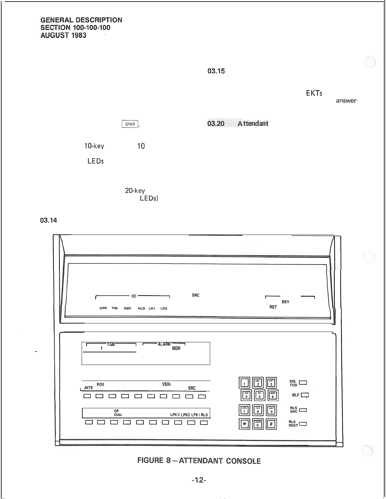
The PERCEPTION attendant console
Console
is the switched-loop type, and its housing is constructed of impact resisitant, off-white plastic.
The layout of the console display panel and
faceplate is shown in Figure 8. A volume control
for the console tone buzzer is located on the rear
of the console behind the busy lamp panel. Modular
jacks for the handset/headset are provided on
both sides of the console. Also, the handset cradle
can be mounted on either side of the console.
The console display panel includes a Busy Lamp
Field and the following displays: Incoming Call
t-
TIE CO
ITGB-
0 1 2 3 4 MAJ MIN
5 6 7 8 9
POS
NITE
BSY
SER
MSG CALL
nuunnnnonn
‘C’ 1
WAT FX
-ALARM
BUZZ CONF FLOW CHG DEST
;;AL
JOIN PAGE LPK4
OVER
INT
RCL
I
MDR
VER/
EXCL EXCL
LPKB LPKZ LPK, RLS
SRC
SRC
CW
“OLD
cos
DEST
~~~1
7
STATUS
RNG
BSY
FIST
HNT VCT TLK
7
FWD DND
ELFa
Page 18
Identification, Calling Source Number, Class of
Service, Call Destination Number and Call Destination Status.
3.22 The Busy Lamp Field (BLF) displays
100 2-digit numbers
with a “hundreds group” identifier that shows
which group is currently being displayed. The
display alternates between groups in response
to operations of the
console keyboard).
(OOw991,
/
and is equipped
key (located on the
DND :Called station is in Do Not Disturb mode
FWD: Called station is forwarded to number
now displayed as
RST: Attempted connection is not allowed.
HNT: Called station was busy and hunting
has
occured
played as DEST.
VCT: Called number does not exist or is
disabled.
TLK: Attendant is in a voice connection with
the called party.
DES-T.
to the number now dis-
Displays:
The Incoming Call Identification (ICI) display
is a backlighted panel that indicates the type of
call
that is currently connected to a console
Loop
/
key. Twelve different displays are
possible:
a” ^^ _^
TIE: TIE trunk
co: CO trunk
WAT: WATS trunk
FX:
OPR: Dial “0” call
RCL: Recall
SER: Serial call
HLD: Held call recall
TIM: Timed reminder (Camp-on, RNA, etc.)
LNI:
LN2:
INT:
The Source (SRC) display is a
7-segment LED display that gives the attendant
the number of the calling station or trunk
equipment number.
Class of Service (COS) is displayed as a
character, 7-segment LED display, giving the
attendant the Class of Service of the calling
-
station.
The Destination (DEST) display is a
ter, 7-segment LED display showing the station
or trunk equipment number called by the
attendant.
The Status (STATUS) display is a backlighted
panel that indicates the status of the called
trunk or station. Eight different displays are
possible:
RNG: Called station is ringing.
SY: Called station is busy.
Foreign exchange trunk
DID call to listed directory number 1
DID
call to listed directory number 2
Intercept
II.^_._^
3character,
3-charac-
3.2 The console keyboard design includes
a display window, two horizontal rows of 10 keys
each, a
four keys.
2
‘l2-key
dial pad, and a vertical row of
The faceplate display window houses the
following displays:
Trunk Group Busy (TGB) provides
numbered
trunk groups 0
ALARM
MAJOR: Alarm occurs when the system is
MINOR: Indicates that the system ringing
MDR: Alarm indicates a problem with
Call Waiting (CW) LED indicates a call is
waiting for the attendant.
The lower horizontal row of keys are all
equipped with
to right) are labeled:
MSG
:
SER CALL: Activates the Serial Call feature.
SP DIAL: Activates the Speed Dial-System
JOIN: Connects two parties which have
LEDs
to indicate the status of
w9.
, ’
LEDsforMAJOR,
not functional and is accompanied by an emergency transfer.
power (DRNG) has failed or the
system time and date was not
reset
initialize.
external SMDR equipment.
Activates the Message Waiting
feature if the attendant is designated as the Message Center.
feature.
reached the attendant on two
different LPK keys.
following a reload or
LEDs
and (reading from left
! 0
.m
MINOR & MDR:
)‘.I
10
:
- I;.,
1
p.
f
,>L /”
”
Page 19
PAGE:
LPK
Provides attendant with a direct,
push-to-talk access to one paging
zone or All Page.
I-4:
The four Loop keys are used for
answering and originating calls.
system clock (while being displayed the clock can be corrected).
BLF: Used to alternate between the
“hundreds groups” displayed on
the console.
. .
)“i
RLS:
The upper horizontal row of keys, with the
exception of the HOLD key, are all equipped
with
%ITE:
POS
BSY: Used to “busy out” one position
SPARE:
BUZZ: Allows attendant to select wheth-
CONF:
OVERFLOW: Transfers waiting calls to an
VER’CHG:
Releases the console from any
connection.
LEDs
and are labeled left to right:
Activates the fixed, flexible and
universal night answering features.
of a 2-console system.
Reserved for future use.
er or not signal tone will be heard
during a Call Waiting condition.
Activates attendant conferencing
(up to six parties including the
attendant console).
alternate answerinq point.
Overrides busy station or trunk
(also used to record an account
- _-
number when extending a call).
RLS SRC: Disconnects the source party from
a Loop key.
R LS DEST: Disconnects destination party from
a Loop key.
03.25 A volume control for the console tone
signal is located on the rear of the console below
the Busy Lamp Field housing.
The console may be used with either
dset or headset, which may be plugged in
on either side of the unit. Also, the handset cradle
may be mounted on either side of the console.
3.27 Two switches are located on the underside of the console. These switches are for emergency use only and are labeled as follows:
EMT: The Emergency Transfer switch allows
the attendant to set the EMT circuits
manually in the event of a system malfunction.
INT:
The Initialize switch resets the system
logic in the event of a system malfunction.
mergency
Transfer
EXCL DEST:
EXCLSRC: Excludes source party from a
HOLD: Holds calls connected to Loop
The dial pad is the standard 12-key alphanumeric configuration and is used to dial both
internal and outgoing calls from the console.
The four keys in the vertical row on the right
of the console are not equipped with
and are labeled top to bottom:
DIS TOD:
Excludesdestination party from
a 3-way conversation.
3-way
conversation.
keys.
Displays time
and date from
LEDs
3.31
DCEC (typically adjacent to the MDF) and is con-
trolled via the DPMU PCB. This unit will connect
eight conventional telephones to eight preselected
trunks. When a reset signal is given to the DPTU
active connections will be protected and finally
reset when they become idle.
Cabinet (DCEC) are made via plug-in connector
cables. Complete installation instructions, including
connection diagrams, programming instructions,
and operational procedures are included in the
relevant sections of the Installation and Main-
tenance manual.
The DPFT is mounted external to the
I
All connections to the Central Equipment
Page 20
04.02
software diagnostics, which assist in pin-pointing
the fault to a particular printed circuit board or
subassembly. A system malfunction is corrected
by replacing a PCB or other subassembly.
5.01
of the PERCEPTION features listed earlier in
Tables B and C along with some associated oper-
ating procedures. Detailed operation instructions
can be found in the appropriate sections of the
system documentation. Software for the features
listed as standard is present in all PERCEPTION
systems.
Access to Paging:
*
CCSA Access:
Class of Service Restrictions:
Code Restriction-3-digit:
.I
Stations may be restricted from toll calls-
i
<‘”
.i
,:
Console-less Operation:
Data Transmission:
PERCEPTION maintenance is aided by
Stan Features
This section contains a brief description
System Features:
2
Allows stations to access and use a
supplied amplifier for voice paging. The system
provides five paging zones, which may be
accessed individually or all together.
Accesses a Common Control Switching Arrange-
ment (CCSA) network for network inward
dialing to the system, direct outward dialing to
the CCSA network, and other features similar
to those provided on the public exchange
network.
The system provides 16 classes of service
which may be assigned to stations to allow
or deny access to features.
a toll call is detected by system analysis of the
first three digits dialed after the trunk access
code.
The system may be operated without a console,
all incoming trunk calls are handled using the
Plight Service features.
PERCEPTION is suitable for voice-band data
applications and is compatible with conven-
tional modems. ,
I
i ,i _
g s. !
T;.X
y‘ I & h
,:;*
’
customer-
Distinctive Ringing:
Three types of ringing are provided to distinguish among station-to-station calls,
to-station calls and automatic callbacks.
Flexible Numbering:
.j
Station directory numbers, as well as trunk
/ J,
and special service access codes, may be assigned
*
in accordance with the numbering plan desired
by the customer.
immediate Ringing:
Ringing occurs at a called station as soon as
it is determined to be idle. There is no delay
caused by waiting for the ringing cycle.
Intercept:
Calls that cannot be completed because of
system restrictions or dialing errors are intercepted and routed to either the attendant or
to overflow tone depending on the type of
call.
Line Lockout:
Stations that do not hang up at the end of a
call, or that go off-hook and do not complete
dialing within a predetermined length of time,
are released from the common equipment.
Multiple Console Operation:
Two attendant consoles,, may be used with
PERCEPTION.
Multiple Trunk Groups:
PERCEPTION can accommodate up to 16
trunk groups.
Music-on-hold and Camp-on:
A standard interface allows connection to a
customer-provided music source. When music
is provided in the system, it is connected to
all calls placed in the hold or camp-on condition by a station or the attendant.
Night Service-Fixed:
When the system is in the night service mode,
incoming trunk calls are routed to preselected
stations.
Night Service-Flexible:
Allows the attendant to assign trunks to
stations for night service. During night service,
incoming calls on these trunks will be routed
to stations assigned by the attendant.
41’siyf #sy .1.: )j :
*
Future Feature
+I
trunk-
Page 21
Night Service-Universal:
Trunks not otherwise assigned by Fixed or
Flexible Night Service will ring a common
bell or chime to indicate an incoming call.
Any station can answer the call by dialing a
specific access code.
Remote Access to Services:
Allows a user outside the system to
the system services via an exchange network
connection. The user dials a preselected DDD
number to connect to the system and then
dials a 3-digit authorization code. The user
may then make any call as if the user were
a system station. This service is provided only
when signalling is on a DTMF basis.
Remote Administration/Maintenance:
System will interface with a standard modem
to allow administration and diagnostic software routines to be accessed from a software
location.
Rotary Dial Compatibility:
The system is compatible with conventional
rotary dial telephones.
acce
Tone Dialing:
When equipped with DTMF receivers
PCS),
PERCEPTION is compatible with 2500
telephones.
Tone-to-dial Pulse Conversion:
DTMF signals from 2500 telephones are
automatically converted to rotary dial pulses
for transmission to a rotary dial central office.
Traffic Measurement:
The system provides traffic information, such
as peg counts and usage, to a terminal or printer.
Uniform Distribution Wiring:
Since PERCEPTION employs a
tronic key telephone, conventional key equipment is not required. It is possible, therefore,
to prewire an installation site with 2 or 3-pair
cable without concern for the future configuration of the system.
Variable Timeout:
The timeout intervals associated with most
features are variable by system programming.
Station Features:
d-wire
(DRCU
elec-
Route Advance:
Routes outgoing calls over alternate facilities The
when the first trunk choice is busy. with either conventional telephones or
irectory
taneously on a mixture of
and
El<Ts.
A maximum of eight appea
is possible for a given directory number
Tandem Switching:
_
Trunk-to-trunk connections through the system
are possible without attend
Tenant Service:
PERCEPTION can be used to serve two tenants.
TIE Trunks:
TIE Trunk
nections to other
Toll
Restriction:
Stations may be restricted from making toll
calls. The system detects toll calls by recognizing “0” or “1” dialed as the first or second
digit following the trunk access code.
@C
-~\i’ki, _. -‘I +,:
,
PCBs
number can appear simul-
500/2500
$1 t:““‘“@
r>, Pt‘
. .
are available to allow con-
PBXs.
nt assistance.
_
“L,..?
c”; ” \
telephones
A/O TE:
fdlowing
Automatic Callback:
Permits a calling station user, upon encounter-
ing a busy directory number or trunk access
code, to operate a dedicated key or dial an
access code which causes the system to monitor
the called number and alert the calling station
when the number becomes idle.
Call Forward-All Calls:
Allows calls destined for a station to be routed
to another station or trunk. The activating
station may be used to originate calls while
the feature is activated.
Call Forward-No Answer:
Any call which is not answered after the end
of a specific time period is automatically
routed to the next DN in the hunting sequence
specified for the called DN. _
Call Pickup-Directed:
A station user can answer calls ringing at
another station by operating the dedicated key
station features are available
ii,, I._(2
EKTs.
:
*Future Feature
Page 22
or dialing a special pickup code and then
dialing the ringing station’s number.
indication is a ring every 20 minutes or an
EKT can be equipped with a
m
key/LED.
Call Pickup-Group:
A station user can operate a dedicated key or
dial a special code to answer an incoming call
ringing on another station within the same
pickup group.
Call Waiting:
During an established call, a tone signal informs
the station user that a trunk call is waiting to
be connected. The called station can accept
the waiting call and then talk alternately to
Qnfere~ce-
Stations may consult with another party
(station or trunk) while on any type of call.
The original party is held during this time an
is excluded from the conversation. The station
user may transfer the held party to the consulted party or the consulte
added to the original conversation to form
a S-party conference.
Direct Outward Dialing:
Station users can gain access to trunks by
dialing an access code.
Do Not Disturb:
Allows a station to give a busy indication to
callers when the user does not wish to be
disturbed.
Hold-All Calls:
A station user may hold any call in progress
by depressing the
special hold code.
‘Manual Line Service
Manual or Hot Line service is provided to
500/2500
user comes off-hook the call is directed to the
attendant or to a preselected DN without
dialing.
Meet-me Page:
Allows the station user to remotely access a
call which was “parked” for him by the
attendant.
Message Waiting:
The designated Message Center can indicate
to a station user that a- message is waiting. The
arty with
j]
telephones only. When the station
ri (,,
1
I
_l_l”. ,.. “_”
sfer:
arty may be
key or by dialing a
!
’
iv-$
I a(i) / i; : ‘” x” :
L
Override:
Enables a station user (after reaching a busy
number) to override the busy condition and
enter the existing conversation on a bridged
basis. A warning tone notifies the existing
conversation that a third party is about to
enter the conversation.
Private CO Line Services:
Permits the appearance of a CO line on an
EKT key or as the number of a
telephone. Upon going off-hook, the station
is connected to the CO by a dedicated trunk
station directly.
alls:
Calls that have been placed on hold by a
retrieved by a different station
ick-up-Directed feature.
Repeat Last Number Dialed:
The system automatically stores the last
number dialed by each station. The number
can be redialed by dialing an access code or
operating the dedicated key.
Speed Dialing:
Enables a station user to dial telephone numbers using abbreviated codes. Two types of
Speed Dialing are provided:
Speed Dial-Station allows the user to
maintain a separate IO-number directory
which may be shared by any number of
stations.
Speed Dial-System
users or attendant to access a system
directory of up to 90 numbers.
Station Hunting-Circular:
Hunting occurs over all station directory
numbers in the group, beginning with the
called number. The call is completed to the
first idle station directory number in the
group. The directory numbers may be arranged
in either consecutive or nonconsecutive order.
Station
Hunting-Distributed:
This is a special circular hunt that provides
c>e ,.
‘i.:”
i
i,
allows the station
500/2500
ring that
f.5 *pp;-; p” ;p p::
system.
gL: ‘.
*
Future Feature
Page 23
a degree of call distribution. Hunting occurs
over all stations in the group in ascending
order by DN. The starting point for each hunt
is incremented for each call regardless of which
DN is dialed. Five groups are possible with
a maximum of eight members per group.
Station Hunting-Secretarial:
Any directory number can be used as the
last number in two or more station hunting
groups.
Station Hunting-Terminal:
Hunting always starts with the called directory
number and ends with the last directory number in the prearranged group; however, the
call is completed to the first idle number.
The hunting sequence can be either consecutive
or nonconsecutive.
Trunk-to-trunk Connections:
A station user can use the Conference/Transfer
feature to connect two trunks.
Uninterrupted Line Connection:
Prevents the insertion of “Warning Tones”
on any given station line. This feature is
intended to provide security for the line(s)
used for data transmission, although other
applications are also possible.
End-to-end Signalling:
The EKT is able to transmit DTMF tones
through the system to the distant end anytime following normal address dialing.
Handsfree Answerback with Speaker Cut-off:
All
EKTs
are equipped for handsfree
back on voice-announced calls. The EKT may
also be assigned a Speaker Cut-off
Activating
answerback and forces all calls to ring the
station.
Handsfree Monitoring:
The handset can go back on-hook for
free monitoring of an on-hold condition.
I-hold Indication: / lc-..:, ?.
A distinctive LED flash is provided to indicate
the call that is on-hold at a given EKT.
i-use Indication:
A distinctive LED is provided to indicate
which Directory Number is currently in use
at a given EKT.
Manual Signalling:
A station user may signal a predesignated
station by operating a dedicated key on the
EKT.
SC0
temporarily defeats handsfree
m
answer-
key.
hands-
NOTE:
The following
on the
Automatic Dialing:
-
Automatic Line Preference:
Call Status Indication:
Common Audible Signalling:
EKT. cd iy
One or more keys may be assigned as automatic dialing keys with each key controlling
a single telephone number. Operation of each
key, after receiving dial tone, causes the
stored number to be outpulsed.
Automatically connects the EKT to its Prime
Directory Number (PDN) upon going off-hook.
LEDs
associated with DN kevs provide a visual
indication of the status of’the call on that
DN by various illumination states.
Permits tone ringing at a station when an
incoming call is presented on any DN appearing at that station.
sration
features are available
Modular Cords:
All
EKTs
are equipped with modular line
and handset cords.
Multiple Appearance Directory Number:
This type of DN has key appearances on more
than one station. Calls can be originated or
received at any appearance.
Non-locking Keys:
All EKT keys are non-locking. l-use and l-hold
indications are provided on DN
vent confusion over which DN is active on a
given EKT.
On-hook Dialing:
Permits the EKT user to dial without lifting
the handset.
Prime Directory Number:
Each EKT has a Prime Directory Number
(PDN) that is selected automatically when
the station user goes off-hook (Automatic
Line Preference). k( ,
LEDs
to pre-
:.
Page 24
Privacy:
Prevents the station user from entering an
existing conversation. Privacy is the inherent
mode of operation for all calls in PERCEPTION.
The only exception is where bridging is specifically provided by use of the
EKT/500
Set Mix feature.
Privacy Release:
By operating the Privacy Release key (if
equipped), an EKT user can permit up to four
more stations to enter a conversation on a
Multiple Appearance DN.
Push-button Dialing:
All
EKTs
are equipped with push-button dial
pads which generate digital messages to be
translated by the system CPU. The buttons
are arranged in the same fashion as a conventional DTMF dial pad.
Push-button/key Access to Features:
The EKT allows simplified access to sophisticated system features via dedicated keys.
Release:
A Release key can be provided on the EKT
which allows the user to disconnect from an
existing call without having to go on-hook or
operate the hookswitch.
Speaker/Amplifier:
Each EKT is equipped with a speaker and
amplifier to produoe the ringing tone, buzz
tone, warning tone and voice-page signals.
Speakerphone:
All
EKTs are,/fully funcfional
‘4% ~#‘.
r
speakerphones.
‘+,
Tone Buzzing:
-
Alerts the EKT user via a buzz tone through
the speaker, used for warning tones.
Tone Ringing:
An adiustable volume
rinqins
tone via the
EKT speaker is used to alert-the user to an
incomina
call.
Y
Voice Paging:
By depressing an assigned key, the calling
EKT user causes a single tone burst to be
sounded at the called EKT. Following the tone,
the caller can speak and be heard through the
called
EI<T’s
speaker. The called station user
answers via handsfree answerback by speaking
Station
it*
directly toward the EKT. If
SC0
is activated,
the call must be answered via the handset.
Volume Control:
The EKT has two volume controls: one varies
the volume level of the ringing tone, buzzing
tone and voice page, the other controls speaker-
phone volume.
Attendant Console Features:
Alarm Lamps:
The attendant console
. .: , \
‘Ts
“.
equipped with
LEDs
1) \
to indicate Major or Minor system alarms.
An MDR alarm is also provided for use with
an external Message Detail Recorder.
Attendant Camp-on with Indication:
Enables an incoming trunk call, which has
been extended by the attendant to a busy
station, to be held until the called station
becomes idle. The busy station hears a tone to
indicate the waiting call. When the called
station becomes idle it rings with the waiting
call. Camp-on and Call Waiting are mutually
exclusive.
Attendant Conference:
The attendant has the ability to establish a
conference with up to six parties (including
the attendant console) or five parties with the
console not included.
Attendant Emergency Transfer Control:
A switch is-provided on the bottom of the
console to manually control the optional
‘__
Emergency Transfer Unit. The switch initiates
:j/transfer action for all emergency lines and
trunks regardless of the system operational
status.
Attendant Initialize:
A switch is provided on the bottom of the
console to initialize the system logic. This
switch is for emergency use.
Attendant Recall:
A station user may recall the attendant to
any
2-party
conference-
Busy Lamp Field:
The PERCEPTION attendant console is equipped with a
busy
DNs)
and a 7-segment display, under
the control of the
IOO-LED
j
panel (displaying
key, indicating which
. .
Page 25
of the two possible hundreds group is being
displayed.
Call Waiting Lamp:
Indicates calls are waiting in the attendant
queue.
Digital Information Display:
Displays five specific call details:
ICI: Incoming Call Identification
SRC: Source or calling party’s number
cos: Class of Service of calling party
DES-T:
STATUS: Status of called party
Direct Access to Paging:
The
vides the operator with direct, push-to-talk
access to one paging zone or to all paging
zones.
Incoming Call Identification:
The ICI section of the console display provides
the attendant with the identity of each type
of incoming call.
Individual Trunk Access:
The attendant can access each trunk individually with the
Destination or called party’s number
1x1
key on the attendant console pro-
\?.* - .( ,,, :\ ” I, .^_
-1
key.
Overflow Facility:
When activated by the dedicated key, the over-
flow facility automatically transfers any
incoming calls which remain unanswered by
the attendant for a specified time period to a
preassigned station or the Universal Night
Answer facility.
Position Busy:
In a
2-console”system,
can be taken out of service by using
key. If both consoles are “made busy”, the
system automatically switches to Night Service.
Push-button Dialing:
The attendant uses a push-button dial pad to
establish all calls.
Secrecy:
Secrecy automatically splits the Source party
from the connection when the attendant
starts to extend the call or answers an attendant recall. The attendant can void the split
manually.
Serial Call:
If an incoming trunk caller wishes to be connected to several stations in sequence, the
attendant can arrange the trunk to recall the
console as each station disconnects.
either of the consoles
\=I
“Interposition Call Transfer:
In a 2-console system, an attendant at one
position can transfer a call to the other position for handling.
-\,
*Interposition Calling:
‘”
Each attendant can call the other for consultation.
*
Lockout:
The attendant is denied the ability to re-enter
an established connection held on the console
unless recalled by the station user.
Night Service Control:
The console operator has the ability to activate
and de-activate Night Service and to post
trunks to specific night stations.
Non-delayed Operation:
The console operator can make a call for a
station user (who has reached the console
by dialing “0”) without requiring the station
user to go on-hook.
Speed Dialing:
A dedicated key provides access to the Speed
Dialing-System feature for the attendant. The
attendant also has the ability to reprogram the
Speed Dial-System directory.
Splitting:
The attendant is able to consult privately with
either party of a call that appearson the console.
Station Number Display:
The SRC and DEST displays show the identity
of any station connected to the console.
Station Verification:
The attendant has the ability to establish a
voice connection with a
connection, periodic bursts of tone alert the
conversation to the attendant’s presence.
Switched Loop Termination:
Each call requiring attendant assistance is
automatically switched to one of four Loop
keys.
busy-
DN. During the
*Future Feature
Page 26
Through Dialing:
At the attendant’s discretion, station users
may complete dialing after the attendant
selects the trunk facility on attendant-handled
outgoing calls.
Timed Reminders-Variable:
The time-out intervals (that determine the
recall of the attendant to the calling party)
are adjustable by system programming.
eaau
res
System Features
Power Failure/Emergency Transfer:
If a control or power failure causes loss of call
processing, selected trunk lines are automa-
tically connected directly to preselected
standard telephones. Optional hardware is
required.
Time of Day Display, Set, Reset:
The time and date from the system’s real-
time clock can be displayed and reset at the
attendant console. : $\
“i:
1
Trunk Group Access Control:
The attendant can restrict dial-access by all
station lines to individual trunk groups. Sta-
tions attempting to dial-access the restricted
groups will be routed to the attendant for call
completion.
Trunk Group Busy Indication:
The console is equipped with
LEDs
showing
an “all trunks busy” condition for up to ten
trunk groups.
Trunk Equipment Number Display:
The SRC and DEST displays show the identity
of any trunk connected to the console.
Trunk-to-trunk Connections:
The attendant has the ability to connect an
incoming trunk to an outgoing trunk through
the console.
Trunk Verification:
The attendant has the ability to establish a
voice connection with an apparently busy
e
trunk or special service access line to determine
if it is in working order. When the attendant
is connected to a busy trunk, periodic bursts of
tone alert the conversation to the attendant’s
presence.
*Direct
Inward
Dialing
(DID):
Stations are assigned
T-digit
listed directory
numbers and can be called directly from the
central office via direct-in-dial trunks.
Call
~~rwar
calls are automatically routed to the atten-
dant when the called station line is busy.
Multiple Listed Directory Number
Allows two
LDNs
to be used for DID
(LDN):
purposes on one installation. Each LDN
can be assigned a unique Incoming Call
Identification (ICI) on the attendant
console.
*Least
Cost Routing:
Provides automatic routing over alternate
customer facilities based on the dialed number
and a customer-specified selection algorithm.
Station Message Detail Recording:
Provides PERCEPTION with the capability
to record (on magnetic tape or hard copy
device) the message data (such ascall duration,
digits dialed, and originating station) of calls
made to and from the system.
Reserve Power:
The primary power supply is designed to
operate from 115 VAC, which is provided by
an optional
charger/inverter
and batteries
mounted outside the equipment cabinet.
Station Features-EKT
20-key E KT:
The PERCEPTION EKT is available in an
expanded 20-key version.
The EKT can be easily converted for wall
mounting with an optional kit.
"Future Feature
Page 27

Page 28
01
TABLE OF CONTENTS.
CONNECTOR TABLE LIST.......................................
ILLUSTRATION LIST.
GENERAL
UNPACKING and INSPECTION ....................................
PACKINGandSTORlNG
CENTRAL EQUIPMENT CABINET LOCATION REQUIREMENTS ........
Commercial Power ...........................................
Reserve Power. ..............................................
Environmental Requirements ...................................
Equipment Room Recommendations. ............................
Cabling Considerations ........................................
Grounding ..................................................
CENTRAL EQUIPMENT CABINET ASSEMBLY. ......................
DFRA Installation ............................................ 3
Power Supply Installation ......................................
Printed Circuit Board Descriptions ...............................
Printed Circuit Board Installation. ...............................
MDF ARRANGEMENT
CABLE CONNECTIONS.
PERIPHERAL EQUIPMENT INSTALLATION
Electronic Key Telephone Connection ............................
Standard Telephone Connection. ................................
Attendant Console Connection. ................................. 15
TrunkConnections
Maintenance Terminal/MODEM .................................
ELECTRONIC KEY TELEPHONE INFORMATION
General ....................................................
EKT Wall Mounting...........................................
Converting the EKT ..........................................
EKT Connections ............................................
SYSTEM INDICATORS and CONTROLS ............................
SYSTEM POWER UP ............................................ 20
MISCELLANEOUS EQUIPMENT CONNECTIONS .....................
General ....................................................
Power Failure/Emergency Transfer. ..............................
Paging Equipment
Music-on-hold ............................................... 25
Universal Night Answer. ....................................... 25
Station Message Detail Recording ................................ 25
....................................................
.........................................
.......................................... iii
.........................................
..........................................
.........................................
........................
...........................................
....................
............................................ 22
i
ii
1
1
17
19
19
19
21
21
21
Page 29
LIST OF CONNECTOR CABLES
DEKU/DSTU
DEKU/DSTU POSITIONS L
DEKU,‘DSTU POSITIONS L 03 * L
DEKU/DSTU POSITIONS L
DEKU/DSTU POSITIONS L 06
DEKU/DSTU POSITIONS L
DEKU/DSTU POSITIONS L 09 WL
DEKU/DSTU POSITIONS L
DEKU/DSTU POSITIONS L
DEKU/DSTU
ATTENDANT CONSOLE
ATTENDANT CONSOLE
PAGING, MUSIC and UNA RING ........................
TRUNK CARD POSITIONS
TRUNK CARD POSITIONS 03
TRUNK CARD POSITIONS
CENTRAL OFFICE LINE CONNECTION & PFT CONTROL
STATION LINE CONNECTION
POSITIONS L
POSITIONS L
#O
#I
.........................
00%
L
01(1/2).
01(1/2) Q
04(1/2) w LO5.
-JL 07( l/2).
07(1/2)-~
10(1/2) -.,
12~
13(1/2) Q
...........................
............................
OObO2 Csc
06~07
L 02.
041 l/2).
L 08
10(1/2).
L Il. ....................
L
13(1/2).
PFT CONTROL .......
~05 &
PFT CONTROL .......
UNA RING & PFT CONTR
..........................
................
.................
.................
.................
.................
..................
.................
.................
L14.
.................
#
.
...
Page 30
MINIMUM DCEC FLOOR SPACE ....................................
GROUND CONNECTION BLOCK
REMOVING DCEC REAR COVER
....................................
...................................
DCECTOPSHELF ................................................
DFRACABLES ..................................................
DPSAFRONT
....................................................
DPSA REAR .....................................................
VOLTMETER CHECK
.............................................
DPSAPINS ......................................................
DPSALOCATION
DCEC CONNECTOR PANEL
DPSACABLES
................................................
........................................
...................................................
DPSA MOUNTING SCREWS ........................................
SLIDING DPSA INTO PLACE .......................................
DPSA GROUND CONNECTION
CLOSED CONNECTOR PANEL
.....................................
......................................
DCECINTERIOR............................................~
DTCUPCB
......................................................
DCCUPCB ......................................................
DPEUPCB
DCOUPCB
DEMUPCB
......................................................
......................................................
......................................................
DCEC REAR CONNECTOR PANEL ..................................
MAIN DISTRIBUTION FRAME......................................
EKT CONNECTION ...............................................
STANDARD TELEPHONE CONNECTION .............................
ATTENDANT CONSOLE #O CONNECTION ...........................
ATTENDANT CONSOLE #I CONNECTION ...........................
IO-key EKT
20-key
......................................................
EKT ......................................................
REMOVING EKT BASE ............................................
EKTWIREACCESS ...............................................
EKT WIRE ROUTING
.............................................
HANDSET HANGER KIT ..........................................
DPSA POWER SWITCH
............................................
INSERTING DISKETTE............................................
DPFT
DPFT FUNCTIONAL DIAGRAM
PAGING WITH
..........................................................
.....................................
MOH FROM SAME AMPLIFIER
........................
PAGING WITH ONE AMPLIFIER ....................................
PAGING
PRINTER CONNECTIONS
WITH MULTIPLE AMPLIFIERS
..........................................
..............................
EXAMPLE: SMDR CALL RECORD ..................................
....
Page 31
This section describes the installation
procedures necessary to ensure proper operation
of the PERCEPTION system.
When the PERCEPTION system is received, examine all packages and make careful
note of any visible damage. If any damage is found,
bring it to the attention of the delivery carrier and
make the proper claims.
Check the PERCEPTION system against
the purchase order and packing slip. If it is determined that equipment is missing, contact your
supplier
tion is started), inspect all equipment for damage.
If any damage is detected, contact your supplier
immediately.
imm~djately.
After unpacking (before the installa-
invet-ter).
Humidity at the central equipment
t (DCEC) location should be within 20 w 80%
(without condensation), and the temperature
should be relatively constant within a range of
32
~104”
airborne chemicals should be avoided.
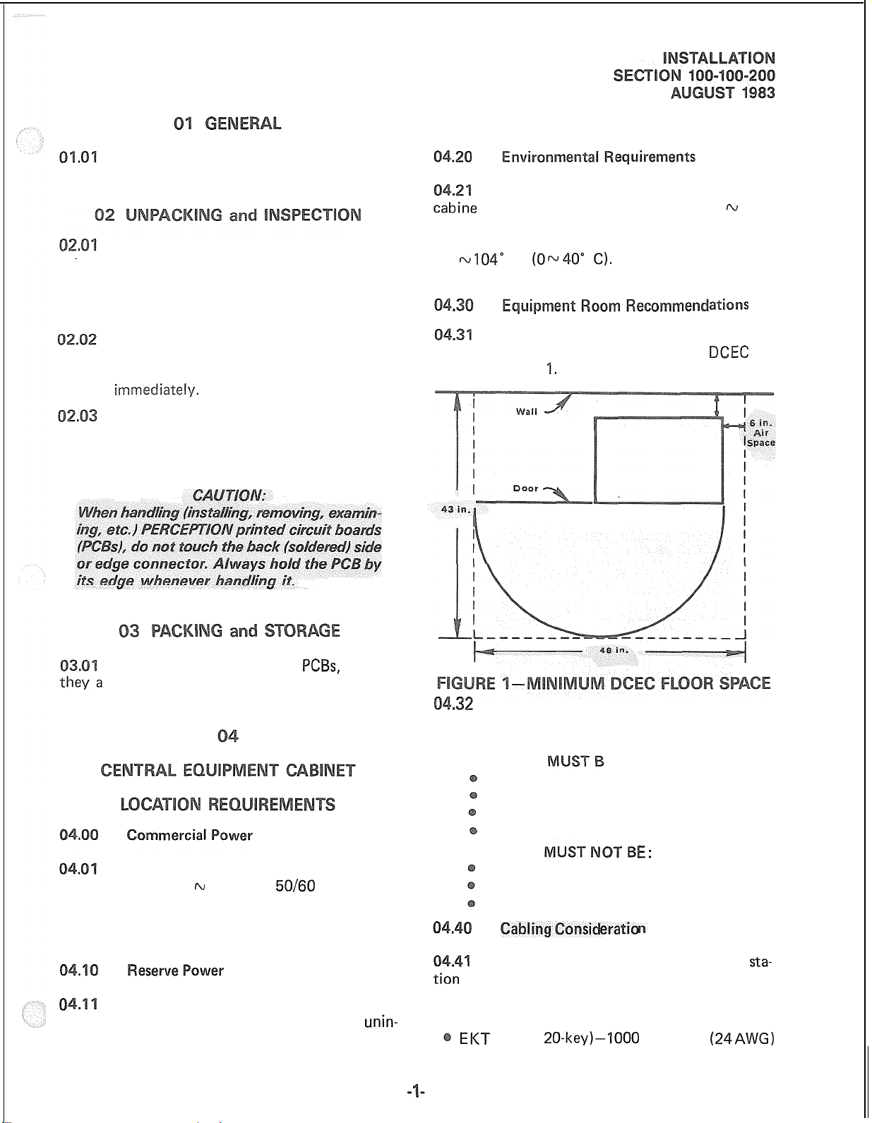
space required for installation of the
shown in Figure
F
(0~40” C).
The minimum floor and maintenance
‘I.
Exposure to dust and
ations
DCEC
is
When storing or shipping
re packed in their original anti-static bags for
protection against static discharge.
The PERCEPTION system requires a
power source of 90w 125 VAC,
a maximum power consumption of 500 watts.
The AC power outlet should be grounded and
separately fused.
0
be provided by a commercially-available
terruptable power source system (battery, charger,
If reserve power is required, it must
PCBs,
50/60
be sure
Hz, and has
unin-
The following requirements must be
considered when selecting a location for the
DCEC:
The location
Dry and clean
Well ventilated
Well lit
Easily accessible
The location
Subject to extreme heat or cold
Subject to corrosive fumes
Next to a reproducing or copying machine
1
The operating loop limits of the
equipment must be considered when choosing
the location of the DCEC. The limit for each type
of instrument:
EKT
(‘IO- or
20-key)-1000
E:
eratio
E:
cable feet
sta-
(24AWG)
Page 32

Conventional telephone-500 ohms (including
telephone)
Attendant Console-1000 cable feet (24 AWG)
Acceptable cable for all telephones is
22 or 24 AWG twisted pair inside telephone
station cable, jacketed but not shielded. Two
twisted pairs are required for an EKT and one
pair for a conventional telephone.
AI
.
” :/.
1
1. Obtain a suitable voltmeter and set it for a
possible reading of up to 250
VAC.
A
25pair
ant console. The console is equipped with
a male 50-pin amphenol-type connector.
The PERCEPTION system requires a
solid earth ground on the ground connection block
located behind the connector panel at the lower
rear of the DCEC (Figure
such a ground may lead to confusing trouble
symptoms in the system and, in extreme cases,
circuit board failure.
cable is required for the
2):
Failure to provide
2. Connect the meter probes between the two
main AC voltage points on the wail outlet.
The reading obtained should be 90 m 130 VAC.
3. Move one of the meter probes to the third
prong terminal
or a reading of 0 volts should be obtained.
. If the reading is
GND
terminal and move the other probe to
the second voltage terminal. if a reading of
OV
is obtained on both voltage terminals, the
outlet.
(GND).
t
properly grounded. Omit steps
oceed directly to step 8.
Either the same reading
V,
leave one probe on the
on one terminal and a
7, and proceed
on one terminal and a
on the other terminal
both probes from the
read-
read-
-
In most installations,
-
United States. the
“third wire ground”-at
outlet will be satisfactory for all PERCEPTION
requirements. However, in a small percentage
of installations this ground may be installed
incorrectly. Therefore, prior to installing a
PERCEPTION system, the third wire ground
must be tested for continuity by either measuring the resistance between the 3rd prong
terminal (earth ground) and a metal cold water
pipe (maximum:1 ohm), or by using a commercially-available earth ground indicator. If
neither procedure is possible, then the test
procedures outlined in Paragraph should
be performed.
within the continental
crrounc
1
provided by the
: the commercial power
7.
Set the meter on
robe on the GN terminal and the other
probe on the terminal which gave a reading
of OV. A reading of less than 1 ohm should
be obtained. If a reading of less than 1 ohm
is not obtained, the outlet is
grounded.
8. If the above tests show that the outlet is not
properly grounded, that condition should
be corrected (per Article 250 of the National
Electrical Code) by a qualified electrician
before the
PERCEPTlON
The central equipment cabinet
the”OHlVlS/Rxl”scale,
system is connected.
place
(DCEC)
Page 33
consists of a single, free-standing cabinet mounted
on casters for easy movement. Assembly of the
DCEC consists of installing the disk drive/ringing
supply subassembly
assembly (DPSA), and the various printed circuit
boards
(PCBs).
(DFRA),
the power supply
5.
5.14
Disk Drive
(DRGU),
To install the DFRA:
a)
b)
4
d)
e)
The DFRA subassembly, housing the
is mounted on the top shelf of the DCEC.
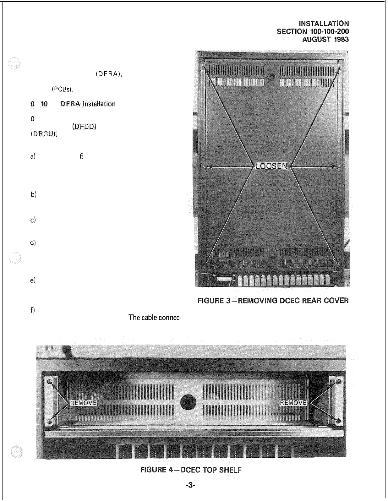
Loosen the 6 screws securing the rear cover
of the DCEC and lift the cover off while
allowing the screw heads to clear the “keyhole”
provided for each screw (Figure 3).
Remove and save the 4 screws from the front
of the DCEC top shelf (Figure 4).
Unpack the DFRA and inspect it carefully
for any visible damage.
The DFRA is shipped with all cables attached
but the connectors may have worked loose
during shipping-check each connector carefully to be sure it is seated properly.
Slide the DFRA into place from the front
of the DCEC. Take care that its cables are
not damaged and do not cause damage.
~stal~atio~
(DFDD)
and the ringing supply
Attach all DFRA cables to the DCEC mother-
f)
board as shown in Figure 5.
tors are all different sizes and each one is
Thecableconnec-
marked to designate its associated jack on the
motherboard.
Page 34

Page 35

g) Secure the DFRA to the front of the DCEC
using the 4 screws removed earlier.
h)
Replace the DCEC rear cover and tighten
the 6 screws.
ground pins and the various voltage outputs.
(Refer to Figure 9; use -24GND pin for testing
the -24V pins,
Verify that the voltages are within the fol-
lowing tolerances:
+5GND
pin for
+5V
pins, etc.)
Power Supply installation
05.21
a single metal chassis. Circuit breakers and LED
indicators for each output, along with an AC
An AC power cord, green ground wire and two
connectors are found on the rear of the unit.
The two connectors are labeled
and will receive the two mating plugs in the DCEC.
05.22 Before the DPSA is installed in the
DCEC, it should be bench tested in the following
manner:
a)
b)
c)
d) Place the DPSA power switch in the
e) Verify that all DPSA power indicator
The DPSA (Figures 6 and 7) consists of
FF switch, are located on the front panel.
J201
and
Start with DPSA power switch off.
Plug AC power cord into AC outlet.
Momentarily depress each DPSA circuit breaker
to be certain that it is not tripped.
position.
are on. If any failures are noted, replace the
DPSA.
J202
0
LEDs
5202
(7) (1)
-
RANGE
-47.52 w48.96 -48
-23.52rv 24.96 -24
+I
1.76- 12.48
-11.76rv 12.48 -12
t-5.0 N 5.4
-5.0
If any failures are noted, replace the DPSA.
05.23 The DPSA is installed in the bottom
shelf of the DCEC (Figure 10) as follows:
(!/DC)
IAJ
5.4
NOM
INAL
+I2
+5
-5
(VDC)
f) The DPSA outputs are checked at the two
connectors
8). Each pin is plainly marked as to what
voltage should be found there. Using a digital
voltmeter (DVM) adjusted to the appropriate
range,
(J201
and
J202)
on the rear (Figure
measure between the corresponding
Page 36
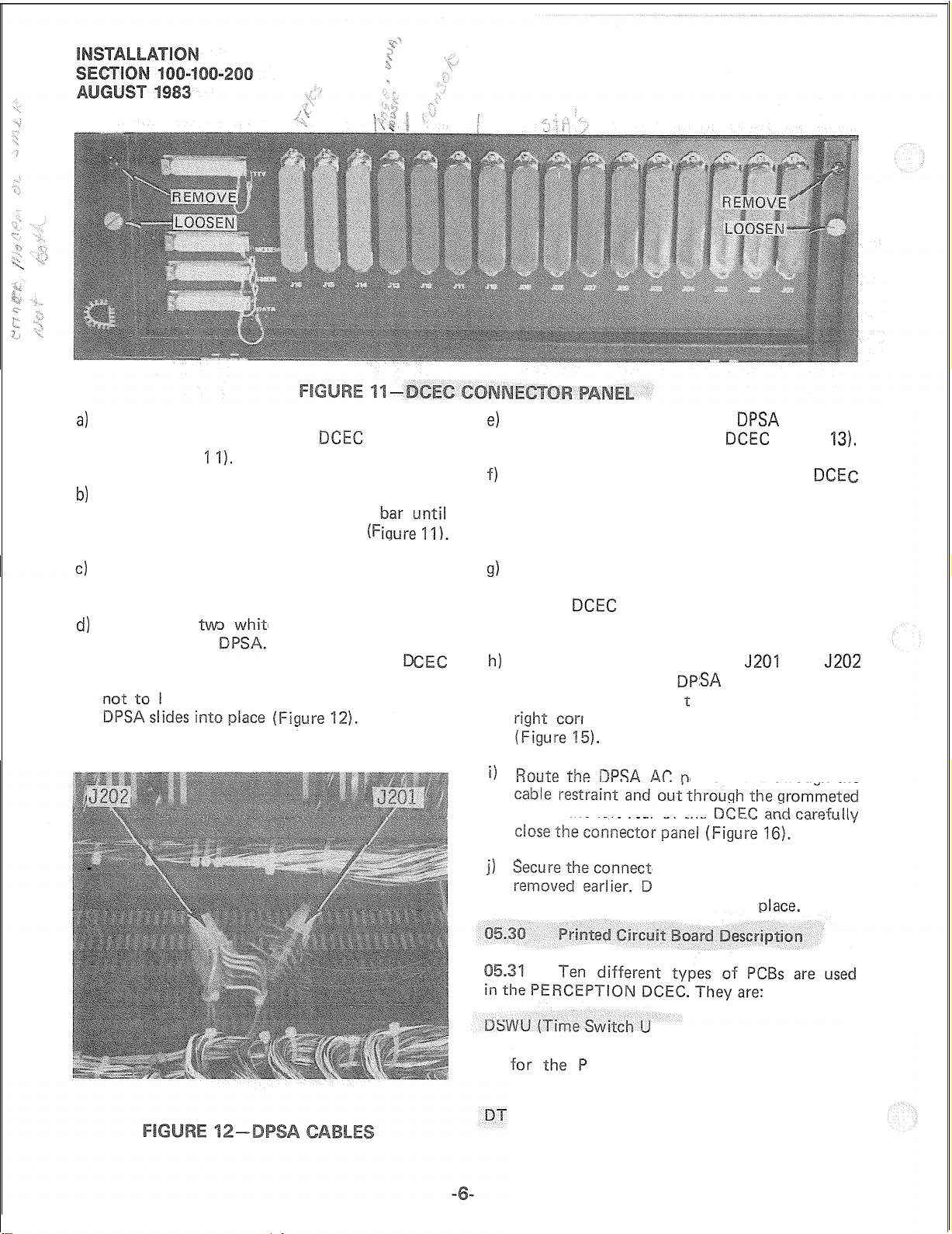
Remove and save the two screws located in
4
the upper corners of the
panel (Figure 1
Loosen the thumb screws that are provided
b)
for securing the connector locking
the connector panel can move freely
I).
DCEC
connector
(F
e)
Remove and save the four
screws from the front of the
f)
Slide the DPSA in from the front of the
(Figure 14). Take care that the AC power cord
passes through the rear opening and that the
ground wire is not caught behind the unit.
DPSA
DCEC
mounting
(Figure
13).
DCE
The connector panel is hinged on the bottom;
lower it carefully to expose the internal wiring.
Locate the
d)
tended for the
ing their
and ensure that they are positioned so as
tw
cables
be damaged or cause damage when the
e plastic connectors in-
Remove the tape secur-
to the bottom of the
g)
Make certain that the DPSA is not crushing
any wires and then secure the front panel
to the
earlier.
D
h)
Plug the two connectors into
on the rear of the
ground wire to the erminal in the upper
il
slot in the left rear of the
1)
locking bar until the cables are in
DCEC
using the four screws removed
J201
and
§A
and connect the
ner of the ground connection block
cord through the
ower
or panel with the two screws
o not install the connector
J202
nit)-one per system:
Performs the time slot interchange function
CM switching, digital padding and
conferencing.
CU (Time Control Unit)-one per system:
Provides the timing and control for the time
Page 37

slot switching on the DSWU PCB and supplies
the system tones.
DCCU (Central Control Unit)--one per system:
Contains the system central processor and
main memory. Performs all system control
functions.
DPEU (Peripheral Equipment Interface Unit)-one
per system:
Performs data transmission and receiving functions between the central control, and all
peripheral equipment, including:
Station
Trunk
Modem interface
TTY interface
SMDR interface
D RCU (Receiver Unit)-one per system:
Optional PCB provides DTMF receivers, which
are required for
telephones. Two types of DRCU
available: DRCU 2-4 and DRCU 2-6. The
m7-‘DRCU
for most systems. For use in systems with
’
extremely high outgoing traffic, the DRCU
‘* ,.
PCBs
PCBs
$‘” _:.
receiving:.dialing
2-4 contains four circuits and is suitable
(
<<‘*
3
.‘(
:
%
from 2500
PCBs
are
Page 38

L-
a
Q
3
cl
L-
-
c
I
i “.
\ “’
Page 39

2-6 (housing six circuits) is available. Only one
DRCU per system is permitted.
DPMU (Paging and Music-on-hold Unit)-one
per system:
This
PC6
is required in every system, and
forms several miscellaneous functions.
Paging interface and control attendant console utilizes one specific EKT
Music-on-hold interface
Power Failure/Emergency transfer control
UNA
signal control ATT #O-PCB position LOO circuit
Attendant Console power transmission ATT
Houses program load and initialize control
switches
entral Office Trunk of fifteen
DCOU PCB
lines to the system. It provides the following
options on a per-circuit basis. DSTU (Standard Telephone Unit)
Loop or Ground Start
600-
or 900-ohm termination
A maximum of eight (8) DCOU
trunk lines) can be installed in a system (see
DEMU).
DEMU (E & M Trunk Unit):
Each DEMU PCB interfaces four E & M Tie
trunks to the system. The DEMU provides
a “Type 1” 2-wire E & M interface with the
option of a
mination, and, under software control, can be
interfac CO/FX/WATS
600-
or 900-ohm voice line
PCBs
per-
(32
ter-
operated in an Immediate Start, Delay Dial,
or Wink Start mode. Each DEMU occupies
a DCOU position and, therefore, a maximum
of eight may be installed in a system.
DEKU (Electronic Key Telephone Unit):
Interfaces eight
used as
circuit.
If that console is not used, a normal EKT
can be connected to that circuit. A maximum
stations) may be i
Interfacese-ightconventional
or rotary dial) to the system. A maximum of
fifteen (15) DSTU or DEKU
tions) may be installed in the system.
5.40
Figure 17. There are no options to select on these
PCBs;
however, there are plug verifications to be
made on the DTCU, DCCU and DPEU boards.
Refer to Figures 18,
the connection plugs are in place at the locations
thrxendant
#I-PCB
Install the DSWU, DTCU, DCCU, DPEU,
and DPMU in their proper positions per
EKTs
position
(15)
‘I9
to the system. It is also
console interface. Each
#I
Ll2
circuit
:
telephones
PCBs (120
and 20 and verify that
#I
(DTMF
sta-
! .>A‘ ;
,l *’
PI;” j I;,
Page 40
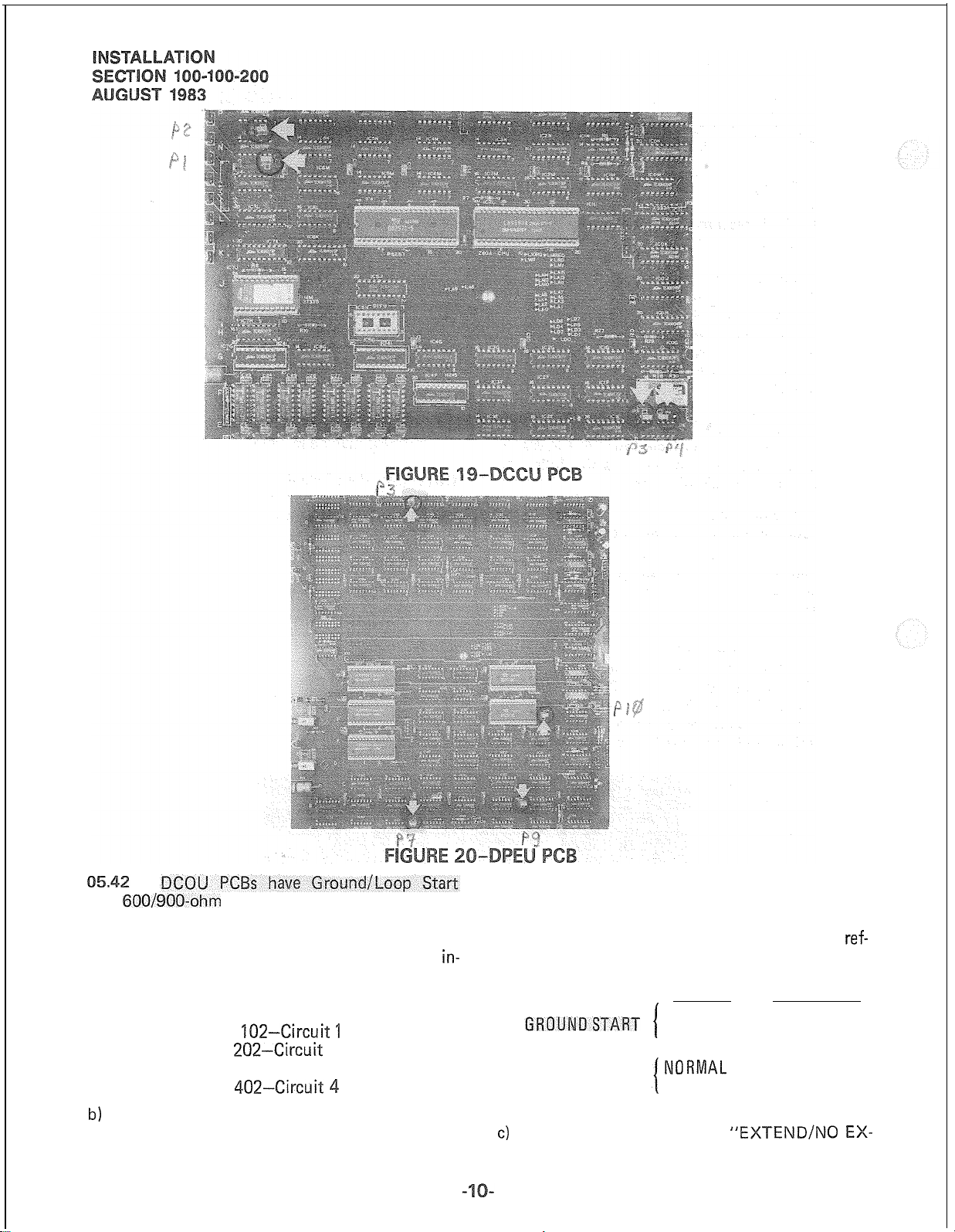
and
600/900-ohm
be selected before they are installed:
a) Ground/Loop Start selections are made
dividually for each of the four circuits using
the strapping terminals (Figure 21).
b)
The strapping terminal consists of five pins
labeled A, B, C, D, and E, and an insulated
termination options that must
TB
102-Circuit ‘I
TB
202~Circuit
TB 302-Circuit 3
TB
402-Circuit
2
4
in-
shorting bar that can connect any one pair
of adjacent pins. Select the desired option
according to the following table. (Note; the
table is printed on each DCOU PCB for
erence.)
OPTION STRAP PINS
NO EXTEND
EXTEND
LOOP START
c)
The GROUND START
NORlVlAL
REVERSE
“EXTEIVD/NO
D-E
B-C
C-D
A-B
ref-
EX-
Page 41

TEND” option refers to the use of “loop
extenders” on long CO lines.
line to be used, and then make the selection
with the shorting bar.
If a battery boost is used on the trunk
line, select “EXTEND’‘-otherwise, “NO
EXTEND” should be selected.
d)
The LOOP START “NORMAL/REVERSE”
option refers to the system’s ability to detect
a pre-ring supervision signal in the form of a
battery polarity reversal on the CO line TIP
&
RING.
If “‘NORMAL” is selected, the system
will not be sensitive to CO line polarity.
If “REVERSE” is selected, the CO circuit
will be “made busy” when the CO reverses
polarity prior to ringing on an incoming call.
-
e) 600/900-ohm
on an individual circuit basis using the strapping terminals (Figure
f)
The strapping terminals consist of three pins
and an insulated shorting bar capable of
connecting two adjacent pins.
g)
Determine the proper impedance for the trunk
termination selections are made
21).
TB 101 -Circuit
TB
201
-Circuit
TB 301
7-B
-Circuit
401 -Circuit 4
‘l
2
3
Connect the center pin to the outer pin
labeled either “600” or “900”.
h)
Install the DCOU
of four circuits) in the slots designated TOO
through TO7 on the DCEC upper shelf (Figure
17).
DEMU
ermination selections that must be made
before they are installed:
a) The selections are made on an individual
circuit basis using the strapping terminals
(Figure 22):
b)
The strapping terminals consist of three pins
and an insulated shorting bar capable of connecting two adjacent pins.
Determine the proper impedance for the trunk
c)
lines to be used and make the selection with
the shorting bar.
Connect the center pin to the outer pin
labeled either “600” or “900”.
PCB(s)
(one for each group
PCBs
have
TB 101 -Circuit
TB
201--Circuit
TB
301-Circuit
TB 401 -Circuit 4
600/900-ohm
2
3
voice
1
Page 42
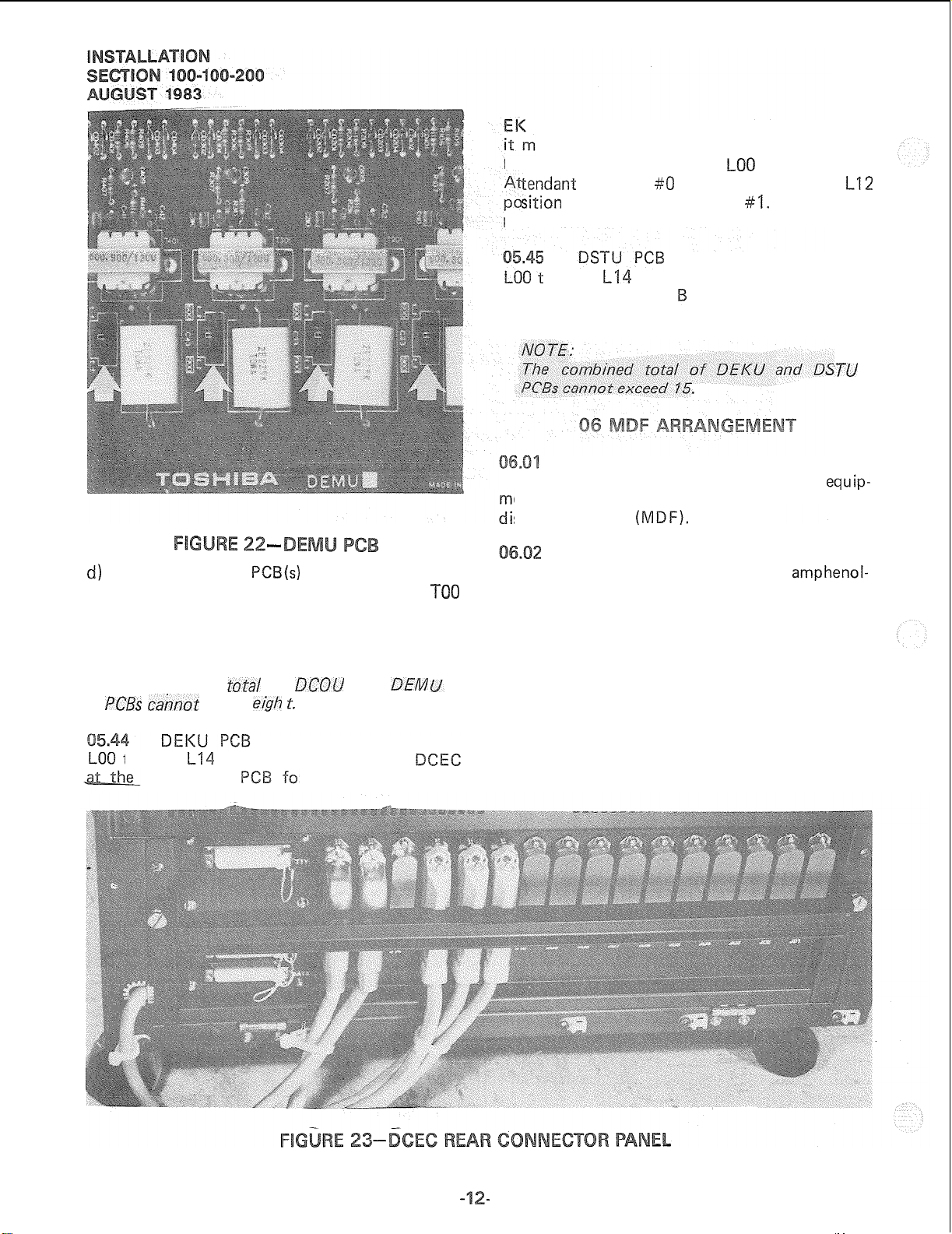
-
d)
Install the DEMU
of four circuits) in the slots designated
through TO7 on the DCEC upper shelf (Figure
17).
NO 7-E:
The combined
PC8s cahnot
through
rate of one
exceed
l-14
PCB(s)
(one for each group
tot-a/
of
DCOU
e&h r.
s are installed in locations
on the lower shelf of the
and
r each group of eight
DEM
TOO
Ts.
If an attendant console is to be installed,
ust be included in the EKT count. A DEKU
PCB
must be used in the
tendant
sition
positions are flexible.
at the rate of one PC for each group of eight
conventional teleohones to be used.
external equipment, such as trunks, station
ent, etc. are made via a customer-provided main
stribution frame
MDF is shown in Figure 24. Cables with
type connectors are attached to the connector
panel of the DCEC and secured with the connector
locking bar (Figure 23). Plastic cable clamps are
provided along the base of the DCEC to secure the
cables. The opposite ends of the cables are then
terminated on “66’‘-type quickconnect terminal
blocks. Split blocks with bridging clips should
be used to allow for fault isolation. Connect each
cable from the DCEC to one side of the block,
external equipment cables to the other side, and
use bridging clips to make the connections.
Console #O is used and in the
for Attendant Console
s are installed in locations
hrough
L14
on the lower shelf of the DCEC
All connections from the DCEC to
(MDF).
A typical layout for a PERCEPTION
LOO
position when
#I.
Other DEKU
amphenol-
LIZ?
‘7-U
equip-
Page 43

PERCEPTION CENTRAL EQUIPMENT CABINET
(AMPHENOL) 1
DCOUI
DEMU
(x3)
DSTU/
1
115VAC ,/’
EXTERNAL
ATT CONSOLE
CHARGER, BATTERY,
r---I
GROUNDF
25-PAIR
INVERTER
_----
DPMU
ATT0
500-TYPE OR
2500-TYPE
TELEPHONE
500-TYPE
l-o co
OR
TIE LINE
OR
06.03
FCC regulations prohibit unregistered
equipment from being terminated on the same
block as trunk lines. It is good practice to separate
trunk lines and all other equipment.
07.01
A listing of connector cables required
for the PERCEPTION system is shown in Table A.
All connections to the system are made
FOR POWER FAILURE
OR EMERGENCY
on the connector panel at the lower rear of the
DCEC and on the Power Failure Transfer Unit.
Cables with standard amphenol-type connectors
are used for everything except the TTY, SMD R
and MODEM terminals.
07.03 Detailed connection information for
each cable is shown in Tables B through S.
Page 44

ection
a)
Find a station Port Number as follows:
PCB Location
LOO hJ L14
EX. LO1
b)
Find a trunk Port Number as follows:
PCB Location
TOO k TO7
EX. TO2
DEKU
PCB
IfCB
Circuit on PCB Port No.
‘ih8
3
Circuit on PCB
IN4
4 TO24
CONNETOR
LO13
Port No.
100-l 00-300, Programming, for inputting infor-
mation concerning the various
must be told which type of
and what key assignment is required.
standard twisted pair jacketed telephone cable.
To accommodate the EKT modular line cord,
terminate the cable in a modular station connector
block at the station location. The standard modular
CROSS-CONNECT BLOCK
See the DEKT Program in Section
EKTs.
The system
EI<T (IO-
EKTs
are connected to the MDF via
BLOCK
or
20-key),
ELECTRONIC
KEY TELEPHONE
(JOI-JlO)
Page 45
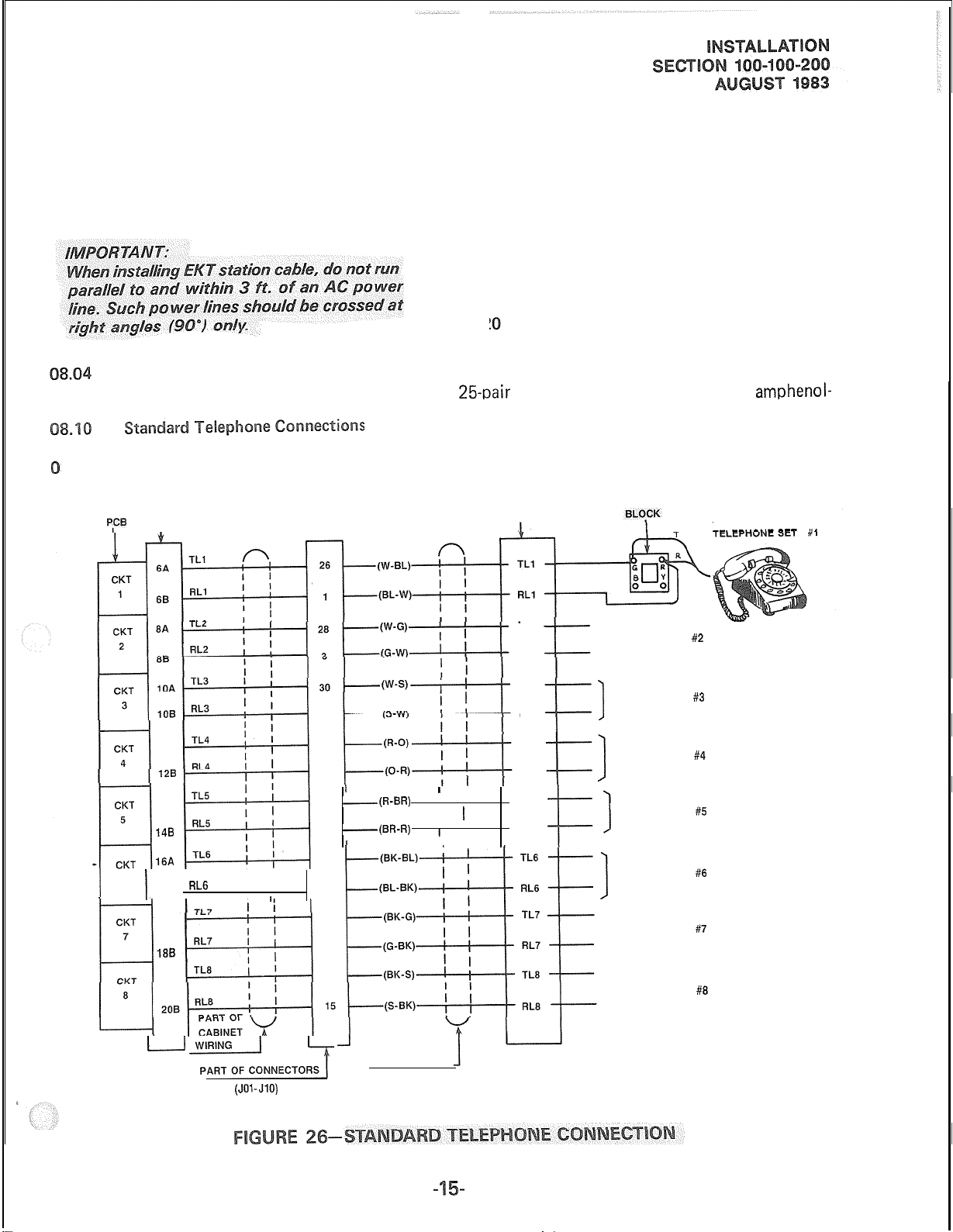
EKT cord length is 7 ft., while the maximum
allowed length is 25 ft.
08.03
The overall length of the cable run must
not exceed 1000 ft. for 24 AWG wire.
100-100-300, Programming, for inputting information concerning single line telephones. The
system must be told which type of telephone
is at each station.
08.12 Conventional telephones require only
single-pair wire and are connected to the MDF
via standard twisted pair telephone cable.
08.13 Standard telephone connection details
are shown in Figure 26.
08.2 Attendant Console Connection
EKT connection details are shown
in Figure 25.
8.11
DSTU
See the DSTT Program in Section
P,CB
6
PCBCONNECTOR
I
12A
14A
148
16A
RL6
16B
I
18A
188
I
I ,
I
I
08.21
The PERCEPTION attendant consoles
are connected to the MDF via industry-standard
25-pair
cables equipped with a female
amphenol-
type connector at the console location.
08.22 Connection details for the attendant
console are shown in Figures 27 and 28.
CROSS-CONNECT BLOCK
5
32
7
-(R-BR)
34
-(BR-R)
9
36
11
38
13
I
I I
I
1
I
I I
I
TL2
RL2
TL3
RL3
TL4
RL4
TL5
RL5
CONNECTING
TO TELEPHONE
1
TO TELEPHONE
1
TO TELEPHONE
I
TO TELEPHONE
TO TELEPHONE
1
TO TELEPHONE
I
500 TYPE OR
2500 TYPE
#2
#3
#4
#5
#6
#7
20A
u
ti~NEcT03
(JO%JlO)
40
PART OF 25
PAIR CABLE
TO TELEPHONE
1
#8
Page 46
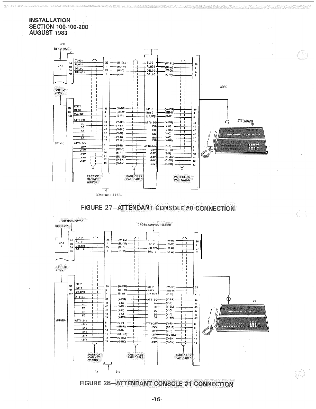
PCB
DEKU it00
i-4
CONNECTOR
/
r-l
CROSS-CONNECT BLOCK
TLOOl -RLDOI -OTLfm.-(W-O)
ORL001.-(0-W)
0 .-(BR-W)
JlYO.-(S-W)
r
CONSOLE
CONNECTOR
CORD
ATTENDANT
CONSOLE
#0
CDNNECTOR
J
1,
1
CONSOLE
CONNECTORCORD
/
------I
ATTENDANT
CONSOLE
#,
t
CONNECTOR
L-J
J12
Page 47
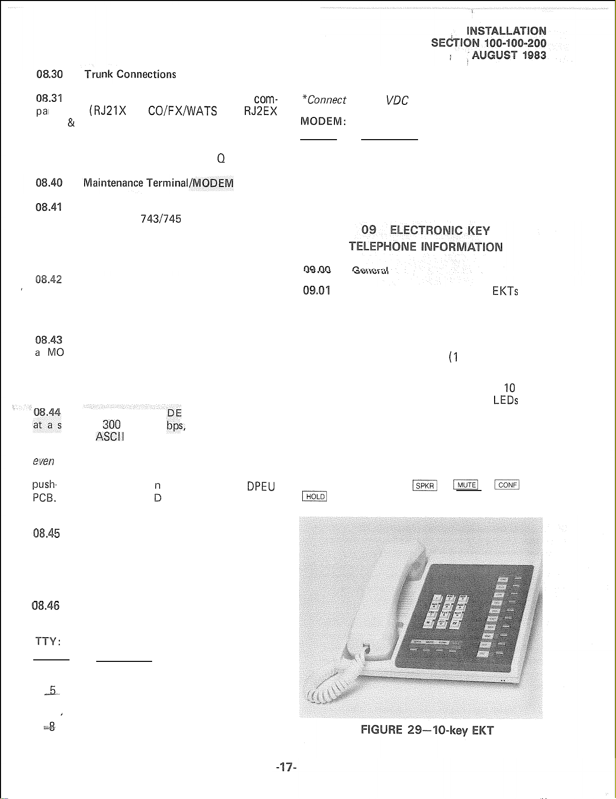
.30
ny jack
Tfll onnecti~~s
Connections from the telephone
(RJ21X
for
CO/FX/WATS
and
com-
RJ2EX
for E & M TIE trunk) should be terminated on a
“66’‘-block, and then cross-connected to the
appropriate leads on the CO portion of the PERCEPTION MDF, using Tables 0, P and 0 as guides.
1
A keyboard/printer terminal (Texas
Instruments Model
743/745
or equivalent) is
required to communicate with the PERCEPTION
system. (See Section 100-I 00-300, Programming,
for operating details.)
The terminal is connected to the system
’
via a female-type RS 232C connector (labeled
TTY) located on the connector panel on the
lower rear of the DCEC.
In addition to the TTY connector,
DEM connector is provided. By attaching
a customer-provided “answer only” modem,
all functions normally performed by the local
terminal can be performed from a remote location.
The TTY and MO M ports can operate
peed
of
300
dard 7-level
or 1200
ASCII
code with one start bit, one
s,
and utilize a stan-
stop bit and one parity bit. The system transmits
even
parity and ignores the parity bit on the
receive side. The speed is selected by a push-on/
-off switch located o
The associated LE
the front of the
DPEU
is on when 1200 bps
is selected.
20
DTR Data Terminal Ready (from
TTY)
*Connect
to + 12
VDC
internally
Pin No. Designation
2
3
4
5
6
TXD
RXD Receive Data (from modem)
RTS
CTS Clear to Send (from modem)
DSR
7 SG
All standard PERCEPTION
Transmit Data (to modem)
Request to Send (to modem)
Data Set Ready (from modem)
Signal Ground
EKTs
may
be used as desk units or wall-mounted telephones.
Each one measures:
Width:
Depth:
Height:
8.8 inches (224 mm)
9.1 inches (230 mm)
4.0 inches
(‘I
02 mm)
and is equipped with 14 line and feature keys in
addition to its push-button dial pad. All 10 keys
in the vertical row are equipped with
LEDs
and
are available for flexible assignment (Figure 29).
Normally one key in the vertical row is designated
as the DN key, while the remaining keys may have
several different designations depending upon
programming. The horizontal row of keys on
each EKT has fixed assignments. Looking from
left to right, they are
IHOLD/
. Of the four, only the speaker key is
ISPKR/
,
j
,
jCONFl
and
equipped with an in-use LED.
The speed selection is made simultaneously for the TTY and MODEM ports. These
two ports are wired in a logical “OR” fashion
and cannot be used at the same time. One must
be “open”.
The pin assignments of the TTY and
modem connectors are:
Pin No.
2
3
,#“!i
6
7
&‘
8
‘
Designation
RXD Received Data (from TTY)
TXD Transmit Data (to TTY)
CTS Clear to Send”
DSR Data Set Ready”
SG
Signal Ground
CD Carrier Detect”
Page 48

2
The
XI-key
same overall dimensions as the standard EKT, and
is installed in exactly the same manner. It provides
an additional 10 flexible assignment keys in the
vertical row.
EKT (Figure
3
Each EKT has a modular handset cord
and is connected to the system via a &conductor
modular line cord.
al
unti
1
An optional handset anger kit is required to convert either type f EKT for wall
mounting. The EKT may be mounted on a wall
or any other flat, vertical surface to which the
base can be secured.
2
When selecting the mounting site, consider the EKT weight and the additional stresses
to which the mounting will be subjected.
3
Mounting screws or mollies, appropriate
for the surface on which the telephone is to be
secured, must be provided by the installer.
Locking tabs secure the base to the
EKT. The direction in which the base is attached
to the EKT determines whether it will be used
as a desk unit or wall unit (it is factory-configured
as a desk unit). Disengage the locking tabs by
pushing downward on the base (Figure
31).
Secure the base to the desired wall
site. Use a spirit level and make certain the top
of the base is level and that the deeper portion
is down.
Route the tail cord through the holes
in the base and secure the EKT (Figure
33).
5
Refer to Figure 32, choose which of
the knockouts are appropriate for the tail cord
route, and then cut them.
Page 49
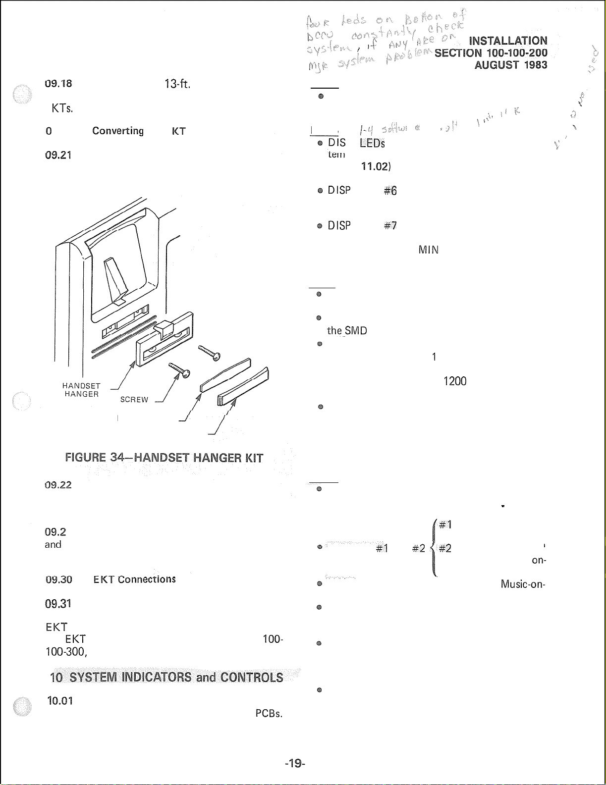
The optional
13-ft.
modular handset
cord is recommended for use with wall-mounted
E KTs.
9.20
Co~w~rti~~
the E
Refer to Figure 34, the optional handset
hanger kit (available from your Toshiba supplier)
must be used whenever the EKT is wall-mounted.
NUMBER CARD
CARD COVER
DTCU
CLOCK LED-flashes continuously when systern is functioning normally.
DCCU
I-“/ s/‘!.: :-
P
LEDs
1 through 8-used to display sys- k’
>
.>>I
\, 1 % ’
‘$, I
status during a program load (see Para-
graph
11.02)
and to indicate the following
fault conditions.
DISP
LED #6 will light to indicate a failure
of the 20 Hz ringing power. This will be
accompanied by a MIN alarm on the console.
DISP
LED #7 will light to indicate that the
system clock has not been set. This will be
accompanied by a
MIN
alarm on the console.
DPEU
MAJ LED-lights when a major alarm exists
in the system.
MDR LED-lights when the DTR signal from
the_SMD
R device is not present.
TTY/MODEM switch-push-on/push-off switch
used to select 300 or ‘I 200 bps speed for TTY
and MODEM ports. An LED visible near the
switch will be on when
1200
bps is selected
and off for 300 bps.
SMD R switch-push-on/push-off switch used
to select 300 or 1200 bps speed for the SMDR
port. An LED visible near the switch will be
on when 1200 bps is selected and off for
300 bps.
f ;r.
2
\
-i
_*
”
’
Remove the card cover by inserting a
paper clip in the hole at one end. Bend the cover
up and remove it and the number card.
Install the handset hanger into place
3
tighten the screws. Reinstall the number card
and card cover.
a
Connect the appropriate length line cord
to the modular connector, route the cord to the
EI<T
and connect to the EKT modular jack. Test
the
EI<T
using the TTRM Program, Section
100-300,
1
Programming.
Several system indicators and controls
are located on the front panel of the various
IOO-
PCBs.
The location and functions are as follows:
DPMU
FALT LED-used to indicate software-detected
faults concerning the MOH or Paging circuits.
See maintenance section for details.
#I
I ights when any
-
page is in progress.
BSY LED #I and
#2 #2
indicates when MOH
is in use (a call is
hold or camp-on).
MOH volume control-used to adjust
Music-on-
hold volume level.
LOAD switch-a momentary switch used in an
emergency condition to reload system program
and data from disk.
INT switch-a momentary switch used in emergency conditions to reset system logic. All
existing calls will be dropped when this switch
is pushed.
PFT switch-a momentary switch used to
manually activate a transfer with the DPFT
unit. A transfer activated by this switch can
only be reset by this switch.
on-
Page 50
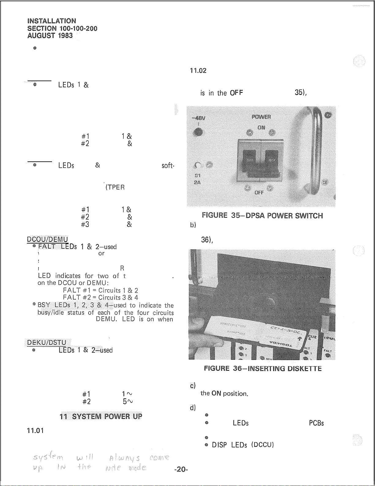
PFT LED-LED is on whenever a transfer
condition, caused by anything other than a
power failure, exists.
D RCU-4
FALT
detected faults or to indicate a disabled state
caused by an input command from the maintenance terminal (TPER Program). Each LED
indicates for two of the four circuits on the
DRCU:
DRCU-6
FALT
ware-detected faults or to indicate a disabled
state caused by an input command from the
maintenance terminal
LED indicates for two of the six circuits on
the DRCU:
ware-detected faults or to indicate a disabled
state caused by an input command from the
maintenance terminal (TPE
LEDs 1 &
FALT #I = Circuits 1 & 2
FALT #2 = Circuits 3 & 4
LEDs
FALT #I = Circuits 1 & 2
FALT #2 = Circuits 3 & 4
FALT #3 = Circuits 5 & 6
EDs 1 & 2-used
2-used to indicate software-
1, 2 & 3-used to indicate
-iTPER
Program). Each
to indicate soft-
Program). Each
he four circuits
soft-
are provided with each system; one should always
be mounted in the drive, the other kept as a spare.
Activate the system as follows:
a) Be sure the main power switch on the DPSA
FF
position (Figure
the AC power cord into the outlet.
b)
Place one of the diskettes in the drive, with the
title appliques on the disk facing up (Figure
361,
and close the drive door.
35),
and plug
on the DCOU or
circuit is busy.
FALT
detected faults or to indicate a disabled state
caused by an input command from the maintenance terminal (TPER Program). Each LED
indicates for four of the eight circuits on the
DEKU or DSTU:
will automatically load its operating system and
customer data from the floppy disk. Two diskettes
LEDs1 &
FALT #I = Circuits ‘l h 4
FALT #2 = Circuits 5% 8
1
Upon initial power up, PERCEPTION
2-used
to indicate software-
c)
Turn the main power switch on the DPSA to
d)
Floppy disk drive will run:
MAJ ALARM LED on DPEU will be on.
FALT
be on.
PFT LED will be on (DPMU).
DISP LEDs (DCCU)
LEDs
on all peripheral
will indicate loading
PCBs
will
Page 51

sequence. LED #4 will light for a short
time and then 1,
loading is complete.
e)
When loading is complete, system will initialize
and clear all
will remain. Refer to Section 100-100-500,
Fault Finding Procedures, for meaning of
indications and assistance with fault clearing.
f)
Refer to Section 100-100-300, Programming,
to complete customer data assignments.
NOTE:
DlSP
LED #7 and the console’s
will be on until the system3 Date and Time
have been set via the console.
LEDs.
2,3,
and 4 will be on until
Only a true fault indication
NIN
LED
eneral
All connections to miscellaneous
are made via J13, TTY, Modem or SMDR
connectors on the connector panel of the DCEC.
NOTE:
The DATA connector is reserved for future
use.
ai~~rel~~~~~ency
The function of the Power Failure/
mergency
cally connect selected trunks to selected conventional telephones in the event of system failure
while permitting normal operation when the
system is in service.
typically on the MDF. Connections to the trunks,
stations and DCEC are made via two 50-pin
amphenol-type connectors
tional diagram is shown in Figure 38.
are normally held operated, thus connecting the
telephones to the DSTU circuit and the trunks
to the DCOU circuits. Should a transfer occur,
the telephones bypass the DCEC equipment and
are connected directly to the trunks.
Transfer Unit
The DPFT is a self-contained module
e
37) that mounts externally to the DCEC,
3 The module consists of eight relays that
In systems where ground start trunks
(DPFT)
(Jl
Transfer
is to automati-
and
J2).
equip-
A func-
are used, each of the assigned station instruments
must be equipped with a grounding push-button
switch if the station is to make outgoing calls
during a power failure.
A transfer can be caused by a loss of
power or triggered manually by either of two
buttons, one of which is located on the under-
side of the attendant console and the other is on
the front of the DPMU PCB. A transfer that is
caused by a power failure will be reset automatically when power is restored; a manual transfer
must be reset manually,
6
When the DPFT is reset after a transfer,
existing conversations will be protected. Individual
circuits will be restored only when they become
idle.
12.17
a)
b)
Using 25-pair cables with amphenol-type
c)
The DPFT is installed as follows:
Mount the DPFT on the MDF.
connectors (female for
connect the DPFT to two “66’‘-type
connect blocks.
Using Table R for a guide:
Connect the trunks selected for
gency
use to the Jl block “CO TIP” and
“CO RING” terminals.
Connect the DCOU circuits relating to the
Jl,
male for
J2),
quick-
emer-
Page 52

TO
DSTU-T1
TO
DSTU-RI
TO
DCOU-Tl
TO
DCOU-
PFT EG
PFT
CONTROL
,
PFT-24V
I
CUR
Jl-26
I
Jl-50
T)
Jl-25
I
-
-
TO
CO-T1
I
I
emergency trunks to the Jl block “DCOU
TIP” and “DCOU RING” terminals.
d) Using Table S for a guide:
Connect the conventional stations, desig-
nated for emergency use, to the proper
terminals on the J2 block “TEL TIP”
and “TEL RING” terminals.
Connect the DSTU circuits relating to the
emergency telephones to the J2 block
“DSTU
TIP” and
“DSTU
RING” ter-
minals.
e)
Connect the DPFT to the DCEC control as
follows: DPFT
Jl
-
DCEC
J14,15
or 16
Pin 25 (S-V) - Pin 25 (S-V)
Pin 50 (V-S) - Pin 50 (V-S)
12.20
2.21
By combining a single customer-supplied
paging amplifier with the PERCEPTION paging
interface and speaker zone switching, it is possible
to provide a paging system of up to five zones
with All Page capability.
12.22
Figures 39 & 40 show possible paging
arrangements. As a standard feature (part of the
DPMU PCB), the system provides a 600-ohm
output to a paging amplifier. If more than one
paging zone is required, the output of the amplifier can be routed back to the DPMU PCB where
it will be switched to one of five sets of speakers
via relays Kl through K5. The relay to be operated
is determined by the access code dialed by the
station user. The actual access code is assigned
in software (see Section 100-100-300, Program-
ming).
12.23
An All Page code can also be defined
in software. When that code is dialed, all relays
will be activated simultaneously to permit paging
to all speaker zones.
12.24
If the power loads of the different
zones are such that a single amplifier is not suitable,
multiple amplifiers (up to one for each zone)
can be connected as shown in Figure 41.
Page 53

-----------m-J
DPMU
PAGING AMP.
I
I
PGI
I
I
h
I
I
I
I
I
PGGND
I
I
e
<
<
------------1
I
I
I
PGOUT 1 , 6
I
nrtn, 1
J13
d
CIll
ZONE
1
ZONE 2
ZONE 3
ZONE
4
ZONE 5
PAGING AMP.
------------A
DPMU
I
I
I
I
I
I
PGGND
MUSIC ] i !
SOURCE,
2
------_------
l-----g
I
MUSIC AMP.
I-------
l---i
IN
1
PUT
!
_____
1
p----J
OUT;
PUT ;
OPTIONAL
I
I
CONNECTION
I
I
Page 54
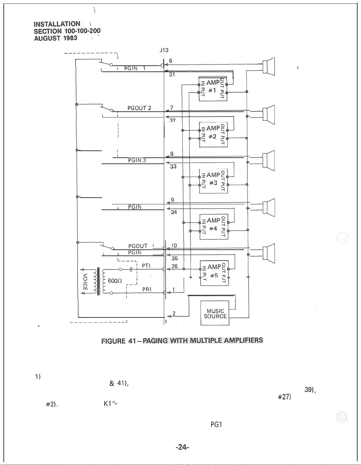
DPMU J13
I
I
I
I
I PGOUT 1
i PGIN 1
I
!
PGOUT2
;
PGlN2
I
I
1 PGOUT3
:
PGlN3
I
I PGOUT4
I
PGIN
I
4
4
ZONE 1
ZONE 2
~
ZONE 3
~
ZONE 4
~
I
I
PGOUI-
I
PGlN
I
I
l---_q
I PGGND
I
5
5
12.25 If background music is to be used on
the paging system, two arrangements are possible:
‘I)
If the music is supplied from a separate ampli-
fier (as in Figures 40 &
41),
it can be con-
nected between the speaker common line and
the PG GND input to the DPMU (J13 pin
#2).
Through the
Kl%
K5 relay “break”
contacts, the music will be connected to all
speaker zones when no page is in progress.
When a page access code is dialed, the proper
ZONE 5
~
relay operates, the music is disconnected
from that zone, and the page amplifier out-
put is connected.
2)
If the music is connected to a second input of
the paging amplifier (as in Figure
PG 1 control lead (J13 pin
#27)
can be connected to the MUTE terminal of the page
amplifier music channel. When any page access
code is dialed, a ground output is applied to
the
PGI
lead to mute the music.
39),
the
Page 55

12.2 All paging connections are made via
J13 in the DCEC connector panel. See Table N
for details.
112.31
A Music-on-hold
(MOH)
interface is a
standard PERCEPTION feature. The circuitry
occupies part of the DPMU PCB. When MOH is
equipped it will be heard by any station or trunks
on-hold in the system, or by any trunk put into
the camp-on state.
12.32 A tuner or other program source must
be provided by the customer. The program source
is connected to the MOH input via pins #4 and
#29
(Br-W and W-Br) of
J13
(see Table N). The
input impedance is 600 ohms.
12.3 Adjust the MOH volume with the MOW
volume control on the front of the DPMU PCB.
Maximum volume is limited by internal circuits
in order to comply with FCC regulations.
niversal
12.
The Universal Night Answer
(UNA)
feature provides an output of interrupted ringing
voltage (85 f ‘IO VRMS, 20 Hz superimposed on
-24 VDC) whenever the system is in NITE service
and an incoming call is received by a trunk designated for UNA. Any station user, upon hearing
the chime or bell, can dial the UNA access code
and be connected to the caller.
j_
12.52
A local
The SMDR output can be connected to:
80-column
printer for an on-line print-
out at the termination of each trunk call.
A recording device to store data for subsequent processing, either on-site or by a service bureau.
12.53 The pin assignments of the SMDR
connectors are:
Pin No
-.----L
3
5
6
7
8
20
*Connected to +
Designation
TXD Transmit Data (to SMDR
device).
CTS Clear to Send”
DSR Data Set
SG
Signal Ground
CD Carrier Detect*
DTR Data Terminal Ready (from
SMDR device)
I2VDC
internally
Ready*
Printers known to be compatible are:
Texas Instruments Silent 700 series
(models
OKI
743/745)
Data model 82A
See Figure 42 for proper connections.
Texas Instruments
743/745
2 The ringing voltage output is intended
ontrol a strategically located chime or loud
ringing bell. The available power is five (5) ringer
equivalents.
Connections to the UNA ringing signal
are via pins
Table N) or J16 (see Table
2.5
Detail Recording
#22
and
#47
(O-V, V-O) of
J13
(see
Q).
The PERCEPTION Station Message
(SMDR)
feature allows a business
to analyze, and thusly control, its telephone costs.
Data can be collected for each outgoing and/or
incoming trunk call. Each such call generates a
call record which is available at the female type
RS232C
connector (labeled SMDR) located on
the connector panel at the lower rear of the DCEC.
TXD
TX0
3 .
3
OKI
Data 82A
3 RD
_
3 RD
Page 56

The data rate at the
ected
as 300 or 1200 bps by operating the
SMDR push-on/push-off switch on the front panel
of the DPEU PCB. When the 1200 bps speed is
chosen, the LED will be lit.
1
7-level
one parity bit (even parity).
The code used by the SMDR is standard
ASCII using one start bit, one stop bit and
SMDR
output may
The recording criteria and Charge
Account code length are defined in the DMDR
Data Block Program (see Section
Programming).
Each time a trunk is seized, information
is collected
The call record is output at t
the following format (see Figure
for that trunk until it is released.
100-100-300,
On an optional basis, it is possible to
the
fo~io~~ng
Incoming calls only
Outgoing calls only
Incoming and outgoing calls
Outgoing toll calls only
All incoming calls and outgoing toll calls
“1
calls seizing a trunk will be recorded’ regardless
of duration. On incoming calls, all answered
calls will be recorded. Calls disconnected by
Toll or Code Restriction features are not recorded.
follows:
enter a Charge Account code of up to 12 digits
into a call record.
When outgoing calls are chosen, all
Timing for recorded calls will start as
Outgoing-when trunk is seized
Incoming to attendant only-when attendant
answers
Incoming and extended by the
when attendant answers.
It is possible for the station users to
recording criteria for each
attendant-
Time
Start of Call
Call Duration
Condition Code (See Table)
A = Attendant handled
D = Call >
E =
Maintenance (SMDR port)
F =
Maintenance (trunk test)
I = Incoming call
I(
= Outgoing call
L = Conference Attendant or 3-party
M = Transfer or Call Forward
=
SPCC #I
=
SPCC #2
Access Code
Dialed Number 15 digits maximum
Calling DN 3 digits maximum
Calling Port Number 3 digits maximum
Account Code
This is a standard call record.
‘IO
Hour - tens
Minute - tens
Hour - units
inute -
Seconds - tens
hours
3 digits maximum
12
digits maximum
-
units
-
units
tens
-
units
-
units
@gy- fg 9
Port
Number
Called DN
‘202’
Access
Code
+
“*3456jssol,r
Account Code
I--?
123456789012
Page 57

The format of the special records, Initialize/Reload
and Time Change is as follows:
Initialize/Reload:
NNNN etc. (previous records-usual call)
00 (Initialize or Reload)
Any record printed after the initialize
record will appear on the same line and
be offset three
colums
from the usual
record.
Example:
NNNN (previous record)
00
NNNNN (init. and next record)
NNNNNN
Time Change:
Following an Initialize/Reload
00 00 00
(elapsed time since Init. or Reload)
MM DD (new date)
HH : MM (new time)
Without Initialize or Reload
MM DD (old date)
HH :MM (old time)
MM DD (new date)
HH
:MM
(new time)
12.63 Some complex calls will cause multiple
call records (CR) for the same station or trunk.
Examples:
1)
Station #I transfers Trunk #I to Station
CR for Station 1
=
Condition Code I or K
CR for Station 2
NTrunk 1
NTrunk 1
#2
= Condition Code M
2) Station #I transfers Trunk #I to Trunk
CR for Station 1
NTrunk 1
#2
= Condition Code I or K
CR for Station 1
WTrunk
2
= Condition Code L
CR for Trunk 1
=
Condition Code M
3) Station #I
CR for Station 1
=
Condition Code I or K
CR for Station 1
holdsTrunk #I
NTrunk
and
Strunk 1
NTrunk
2
callsTrunk #2
2
= Condition Code K
FROM
0. DCEC TO
1
2
3
4
5
6
7
8
9
10
11
12
13
14
15
16
17
18
*(l/2)
indicates that only the first four or last four circuits of that
**Attendant console requires a male connector at the DCEC and a female connector at the console location.
MDF
MDF
MDF
MDF
MDF
MDF
MDF
MDF 1
MDF
MDF
MDF
MDF
MDF
MDF
MDF
MDF
FROM PFT PFTCONN.
TO MDF NO.
FROM PFT PFT CONN. STT LINE & DSTU
TO MDF
DCEC
CONN. NO.
JO1
JO2
JO3
JO4
JO5
JO6
JO7
JO8
JO9
JIO
Jll
J12
J13
J14
J15
J16
Jl
NO. J2
CONTENT OF CONNECTOR
DSTU/DEKU
DSTU/DEKU
DSTU/DEKU
DSTU/DEKU
DSTU/DEKU
DSTU/DEKU
DSTU/DEKU 09’L10(1/2)
DSI-U/DEKU 10(1/2)‘~11
DSTU/DEKU
DSTU/DEKU
DCOU/DEMU
DCOU/DEMU
DCOU/DEMU
CO LINE & DCOU
OO%Ol (l/Z)”
01(1/2)sO2
03%04(1/2)
04(1/2)%05
06%07(1/2)
07(1/2)%08
12%13(1/2) M
13(1/2)‘~14
ATT 0 M/F**
ATT 1 M/F
DPMU
OO’LO2
03,x05
06%07
00~07
(maximum: 8) (maximum:
00%14
(maximum:
8)
(maximum: 8)
PCB
are connected to that cable.
8)
CONN. REQUIRED
ON CABLE TABLE
M
M
M
M
M
M G
M
M
M K
M
F
F P
F
F R
M
DESC.
8
C
D
E
F
H
I
J
L
M
N
0
Q
S
Page 58

PAIR
IT
PIN
26 W-BI
R 1 1 1 BI-W
2T 1
R j
3T
R
4T
R
5T
R
6T
R
7T
27
2 1 O-W 1 DRL
28
(
3
1
29
1
4
30
5
31
6
32
COLOR
CODE RESIGNATION
1
W-O
1
W-G
1
G-WI/
1
W-Br
1
Br-W
1
W-S
s-w
R-BI
BI-R
R-O
TL
RL
1 DTL
/ TL
RL 002
I
DTL
1
DRL 002
1 TL
RL 003
DTL
DRL 003
TL
LEAD
001
001
001
001
002
002
003
003
004
/
R / 7 1 O-R / RL 004 / RING-LINE
t-
8T 1
R
9T
R
33
1
R-G
/
DTL
004
1
8
/
G-R
R-Br
Br-R
IOT
5
, RING-LINE
6
I DATATIP-LINE
12
38
--
13
39
14
40
41
/ 0-Bk 1
/
1
R
1
13T
/
R
14T
R
15T
R
/ 15 / S-Bk / RL
j
16T
j
R 1 16 1
17T
1
42
j Y-O
17
1
R
1
18-i-
1 43 1 Y-G / D
R
1
19T
1
.-.
R 1
. .
20T
R
/
18
1 G-Y 1
44
1
IR
1
.- L. .
45
20 S-Y
217 46
R 21
77T A7
I
n
I
LL
I
L31
/
R
I ~~
I 24T 1
R
25T
R
*c,
,
1 23 1 G-V 1 RL 014 1
AQ
I
1”
24
50
25
Rk-G
-.. -
G-Bk
Bk-Bt
Br-Bk
Bk-S
Y-BI
BI-Y
1 DRL 00
O-Y 1
Y-Rr
-.
Rr-Y
Y-S
V-B/
BI-V
\I 43
V-V
v-u
\f.Rr
1 wll
Br-V
v-s
s-v
DRL 006
/ TL
RI
DTL
DRL 007
TL
/ DTL
1 TL
RL 011
DRL 011
1
TI
.-
I RI
I.L
DTL 012
DRL 012
TL
RL 013
i-3TI
I
UriL lJ13
/ IL
DTL 014
DRL 014 1
007
007
007
008
00s
008
8
011
TL 011
012
-.
nl
2
V.
013
nl3
Ul4
SPARE
I,
j /
/ RING-L
I
1 DATATIP-LINE
I
FUNCTION
TIP-LINE
1 RING-L
/
.INE
D,il,T,C,TIp-LINE
DATA RING-LINE
1 TIP-LINE
1
RING-L .INE
I
DATATIP-LIN
E
j DATA RING-LINE
/ TIP-LINE
RING-LINE
DATA
,-Ip-LI,QE r-l/T
-
DATA RING-LINE
TIP-LINE
1 DATATIP-LINE
/
DATA RING-I INE
DATA RING-LINE
I
.
TIP-LINE
.INE
RING-L
DATA TIP-LINE
DATA RING-LINE
CKT 007
CKT 007
TIP-LINE
.INE
DATA TIP-LINE
DATA RING-LINE
TIP-LINE CKT
RING-LINE
DATA
TIP-
LINE CKT 011
DATA
c-1 irklc f-u-r nil
RIN,
,slsvL
TIP-LINE
RING-LINE
DATA TIP-LINE
DATA RING-LINE
TIP-LINE
RING-LINE
DATA TIP-LINE
nATA
RING-LINE
TIP-LINE
RING-LINE
r
-,..,.
DA-i-A
I
,/
SING-LINE
-
CKT
001
CKT 001
PI/-I-
nnl
cII\, ““I
f-~-r
vs., vv
CKT
,
nni I
>
002 I’
CKT 002
f-w-r nn9
bI\ I ““L
i-~-r
“,,,
CKT
nn9
VVL/,
003
,
I
/
CKT 003 1
nn-2
1 rr
CKT 004 1
CKT 004 1
CKT
005 ) ”
CKT
005 1
CKT 005
CKT 005
CKT 006
CI(T
006
CKT
006
Cl<T
006
-...-...
CKT
007
CKT
007
CKT 007
CKT 007
CI<T
007
CI<T
007
CKT 008
CKT 008
CKT 008
CKT 008
CKT 008 /
ru-r fm2
u,.., “vu
PI/-r n,,
b,\, “I I
ut\a
,..I,C ,-.“_
LKi UIL
CKT012
011
v,,
I
,
DEKU/DSTU
1
I
,
”
CKT 012
CKT 012 1
CKT 013 1
CKT 013 1
(-V-r nl(-l
cIn,
U1.3
CKT013
CKT014
(-‘KTn14
“,\I
ZKT014
ZKT
_.
-.
.
014
I
I
PCB
POSITION
DEKUIDSTU
”
II
LOO
”
I,
I, I, ,I
lf
”
”
r,
I,
”
II
I, I,
”
” ‘I ”
II I,
” ” ”
” ” ‘I
”
” ” ”
“
”
“
”
”
“
”
“
”
”
”
”
”
”
”
”
I’
”
I’
”
”
”
”
”
”
”
”
,,
I,
”
I, ,, I,
”
”
”
”
”
”
”
”
”
” ” ”
I, I,
,I I,
”
LO1
I, I, I,
”
”
”
” ” ”
” ” “
” ” ”
,I I, I,
”
”
”
”
”
”
”
”
”
”
”
II
1’
‘J
1,
1’
,,
”
”
”
”
”
”
I,
“
“
”
”
”
”
”
”
‘I
‘I
(l/2)
”
“
I’
I‘
”
”
”
‘I
I
I
I
Page 59

PAIR
IT
2T 27
3T
4T
5T
6T
7T
~
8T
9T
IOT
L
IIT
12T
R
R 2
R
R
R
R
R
R
R
R
R
R 12
PIN
26
1
28
3
29
4
30
5
31
6
32
7
33
8
34
9
35
IO
36 Bk-BI
11
37
13T 38
R
14T
R
13
39 Bk-Br
14
023
15T 40 Bk-S
R 15
16T
41
R 16
17T
R
181
R
3
42 1 Y-O
_-
I/ U-Y
43
18
COLOR
CODE
W-BI
Bl-W
W-D
n-w 1
*---
LkAU
DF.(
,
--;iGNATIQN
1 TL
1
RL 015
1
DTL
’
1 DRL
-..
W-G
G-W
W-Br
Rr-W
-..
.
w-s
s-w
R-BI
BI-R
R-O
O-R
R-G
G-R DRL
R-Br
Br-R
R-S
S-R
TL
RL
DTL 016
IDRL
TL 017
RL 017 RING-LINE
DTL 017
/ DRL 017 / DATA RING-LINE
TL
RL 018 RING-LINE
DTL 018 DATA
TL
RL 021
DTL
DRL 021
TL
BI-Bk
DTL 02.2Bk-0
0-Bk
Bk-G
RL 022
DATA TIP-LINE
DRL
TL
G-Bk RL 023
DTL 023
Br-Bk
DRL
”
TL
S-Bk
Y-BI
BI-Y
-
. .
Y-G
G-Y I
RL 024
D’
i-L
024
DRL 024
TL
1
RL 025
DTL
1
/ DRL 025 1 DATA RING-LINE CKT 025 ” ”
-.
rL 026
I
015
015
015
016
016
TIP-LINE
1
RING-LINE
/
DATATIP-LINE CKT
1 DATA RING-LINE
TIP-LINE
RING-LINE CKT
DATA TIP-LINE
016
1
DATA RING-LINE
TIP-LINE
DATA TIP-LINE
018 TIP-LINE
018
021
DATA RING-LINE CKT
TIP-LINE
RING-LINE
02
!I
DATA TIP-LINE
DATA RING-LINE CKT 021 ”
022
TIP-LINE
RING-LINE
_
022
023
DATA RING-LINE CKT 022
TIP-LINE
RING-LINE
DATA TIP-LINE
DATA RING-LINE CKT 023
024
TIP-LINE
RING-LINE
DATA TIP-LINE
DATA RING-LINE CKT 024 ”
025
TIP-LINE
/ RING-LINE
025
DATATIP-LINE
1
/
DATA
FUNCTlON
TIP-LINE
CKT
-...
CKT
CKT
CKT
-... -.-
CKT 016
CK?
CKT
-...
CKT
CKT017
CKT
(
XKT
7KTnlQ
c..
C.KT 071
-...
,
.:KT
-.., --.
CKT021
CKT 022
CKT 022
CKT 022
CKT
-..
CKT 023
CKT 023
”
CKT
-... --.
CKT
-.., --.
CKT 024
CKT 025
IKT
c
. . .
CKT
>I\,
:KT
_...
:KT
017 /
018
.
---
026 1”
015
_
llc;I
0.”
015
015
016
016
016
017
-.,
017
y,”
--.
034
Y&Y
i-i%
“L,J
Y-v
I
DEKU/DSTU LO1
”
,
”
1
I’ ‘I
1
”
“
”
1
1’ IJ 1’
/
I’
”
”
‘*
”
”
/
018
1 ” ‘I
1
DFKI I/nSTI
..-.....,-,
fl71
1
”
”
”
” ”
”
fl73
1
”
”
” ‘I
n7A
1
”
“
n3F;
I’
(r
1
Fl9R
”
PCB
POSITION
,I ,I
‘I
1’ 11
I’
II
‘1 1’
I’ ‘I
‘I
I,
“
”
I
.. .”
‘I ” ”
I’
” I’
” ”
” ”
,,
”
”
” “
”
” lr ”
”
” ”
“
”
II I,
”
”
(l/21
I
‘1
1’
$1
1’
I’
I,
,
”
”
”
LO2
i
“
‘I
,
7
”
1
I
‘I
”
”
‘I
“
‘I
”
“
”
SPARE
,I
I
I
I
Page 60
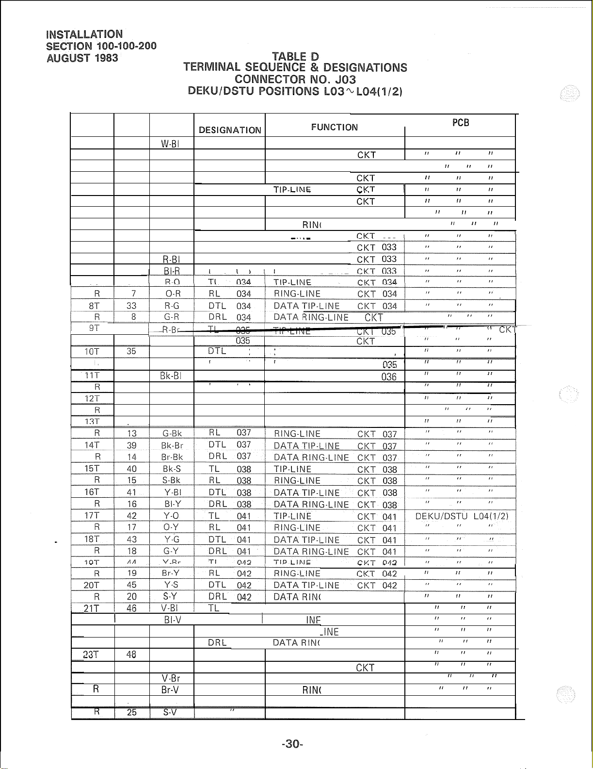
PAIR
IT
R
2T
R
3T
R
4T
R
5T
R 5
6T
R
7T 32
PIN
COLOR LEAD
CODE
26 W-BI
1
27
2
BI-W RL 031
w-o DTL
o-w
28 W-G
3
G-W RL 032
29 W-Br
4
Br-W DRL 032
30 w-s
s-w RL 033
31
6
R-BI
BI-R DRL 033
DESIGNATION
TL
031
TIP-LINE CKT
RING-LINE
031
DRL 031
TL
032
DATA TIP-LINE CKT 031 1
DATA RING-LINE
//
TIP-LINF
RING-LINE
DTL 032
DATA TIP-LINE CKT 032
DATA
TL 033 / TIP-I INF
j RING-LINE
DTL
033
/ DATA-TIP-LINE
/ DATARING-LINE
FUNCTICI~
-.--
RIN(
_..
.-
.A,
I
POSITION
CKT
031
031
DEKU/DSTU
”
‘1 11 1’
1
CKT
CKT
-..
CKT
031
032
032
.-
11
j
1’
11
”
;-LINE CKT 032 / ”
CKT
033 /
PC5
” ”
1’ f~
)I
11
‘I
“ I’
LO3
11
1’
”
1
/ 1
R
R 10
R 1 21 1
22-r 47
R
37T
LY.
R
24T
R
25T
3ING-LINE CKT
34
9
36
11
37
12
38
TL 035 TIP-LINE
Br-R RL
R-S
S-R
Sk-B1
BI-Bk
RING-LINE
Bk-0
0-Bk
Bk-G
035
D-I-L.
035 DATA TIP-LINE CKT 035
DRL 035
TL
036
RING-LINE
DATA RING-LINE CKT
TIP-LINE CKT
RL 036
DTL 036
DRL 036
TL
037
DATA TIP-LINE
DATA RING-LINE CKT 036 ”
TIP-LINE CKT
034 / ” ”
”
CKT
035
035
_--
036
CKT 036
CKT 036
037
”
”
”
”
”
” ” ”
‘I
”
”
I’
‘I ‘I
I’
‘I ”
”
I’ I’
”
CKT
”
”
I’
”
”
_.., _.-
043 / TIP-LINE CKT 043
BI-V
/ RL 043 t RING-I
v-o DTL
043
1 DATA TIP-L
INF
22 O-V RRL 0431DATARIN(
‘a?
.w
23
49
24 Br-V
50 V-S
V-G
TL
G-V RL
V-Br
D-I-L 044
DRL 044
044
044
SPARE
TIP-LINE CKT 044
RING-LINE
DATA TIP-LINE CKT 044 I
DATA
RIN(
CKT na?
;-LINE CKT 042
CKT 043
-INE
CKT 043
;-LINE CKT 043
CKT
;-LINE CKT 044
I
044
“
” ”
” ”
”
”
”
”
“
”
”
”
”
”
”
”
” ” ”
“
”
”
”
”
”
“
It
I
”
035R-BI
Page 61
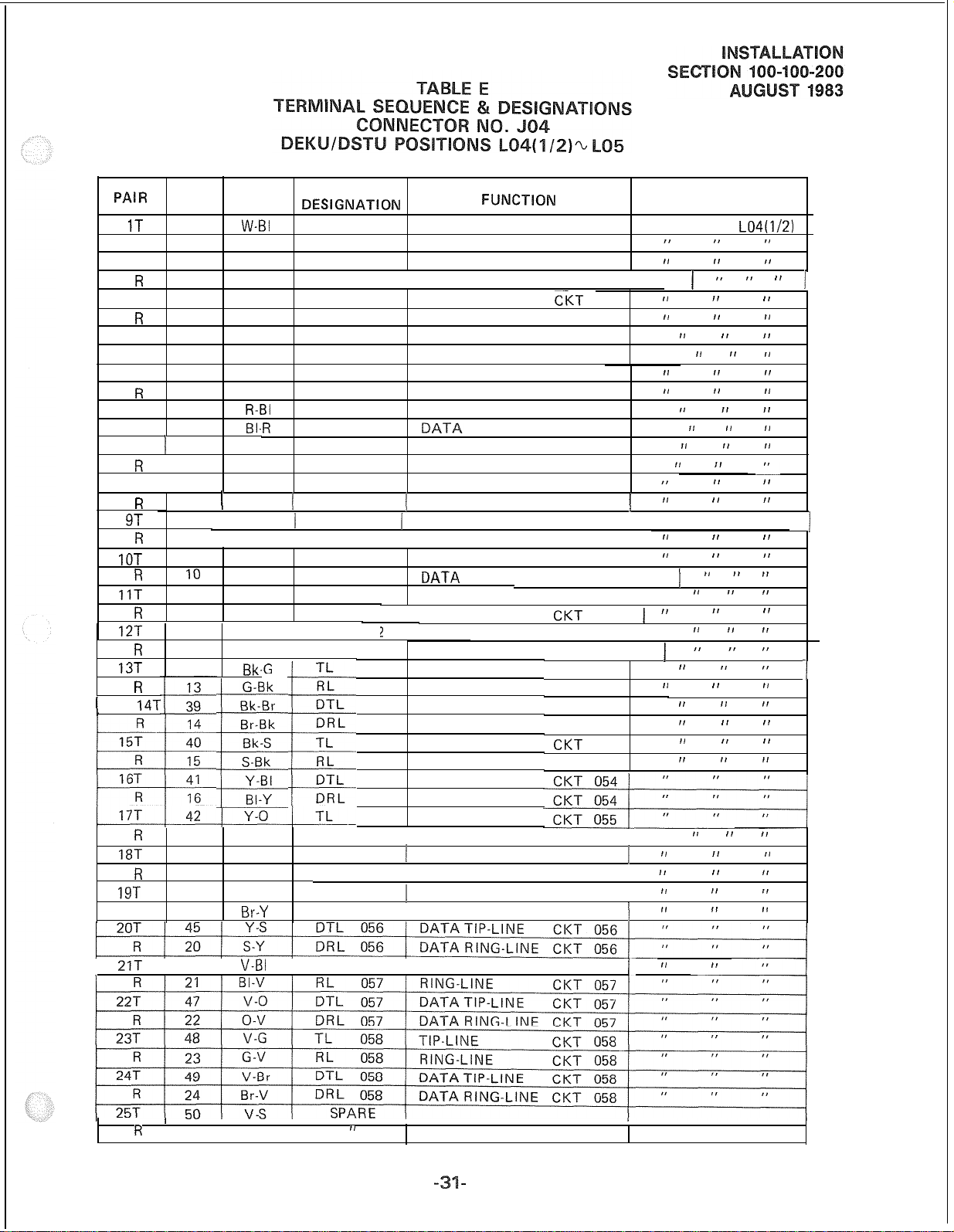
PAIR
1T
R
2T
R
3T
R
4T
f?
5T
R 5
6T
R 6
7T 1 32 ’
R
8T I 33
R
9T
R
IOT
R
11T
R
12T
R
13T
1
R
(
R
18T 43 Y-G
R 18
19T 44
R 19
14T
PIN
26
1
27
2
28
3
29
4 Br-W
30
31
/
7
8
34
9
35
IO
36
11
37
12
38
17
COLOR
CODE
W-61
BI-W RL 045
w-o DTL
o-w DRL 045 j DATA RING-LINE CKT 045 1 ” ” ” 1
W-G
G-W RL
W-Br
w-s TL
s-w RL 047
R-BI
BI-
R
R-O
O-R RL 048
R-G
(
G-R
1 R-Br j TL
/
Br-R
R-S
S-R
Bk-Bl
BI-Bk
Bk-0 j DTL 05:
0-Bk 1
-G
Bk,
G-Bk
Bk-Br
Br-Bk
Bk-S
S-Bk
Y-BI
BI-Y
c
O-Y
G-Y
Y-Br TL
Br-Y RL 056
LEAD
DESlGNATION
TL
045
045
TL
046
046
DTL 046 DATA TIP-LINE
DRL 046 DATA RING-LINE CKT 046 ”
047
DTL 047 DATA TIP-LINE
DRL 047 RING-LINE CKT 047
TL
048
DTL 048 DATA TIP-LINE CKT 048
(IDRL 048
051 j TIP-LINE
1
RL
051
DTL
051
DRL 051
TL
052
RL
052 1
DRL
052
053
053
053
053
054
054
054
054
055
RL
055 j RING-LINE
DTL
055
DRL 055 / DATA RING-LINE CKT 055 /
056
TIP-LINE CKT
RING-LINE CKT
,
DATATIP-LINE CKT
TIP-LINE
RING-LINE CKT
TIP-LINE CKT
RING-LINE CKT
TIP-LINE
RING-LINE
1 DATA RING-LINE CKT
1 RING-LINE CKT
DATA TIP-LINE CKT
I
IATA
TIP-LINE
RING-LINE
?
/ DATATIP-LINE CKT 052 j ”
DATA RING-LINE
TIP-LINE
RING-LINE
DATA TIP-LINE
DATA RING-LINE
TIP-LINE
RING-LINE
DATA TIP-LINE
DATA RING-LINE
TIP-LINE
1 DATATIP-LINE CKT
1 TIP-LINE CKT
( RING-LINE CKT
FUNCTlON
045 DEKU,‘DSTU LO4(1/2)
045
045
046
CI(T
046
CKT 046
047
047
CKT 047
CKT 048
CKT 048
048
1
CKT 051 1
0517
051
1
RING-LINE CKT 051 1 ” ”
CKT 052 / ”
CKT
052 1
CKT 052 1
CKT 053
CKT 053
CKT 053
CKT 053
CKT
054
CKT 054
CKT 055 j ”
055
1
056
1
056
1
PCB
POSITION
”
”
I’
”
‘I
” ”
”
”
”
”
‘I ”
,I
((
I’
II
DEKU/DSTU LO5 1
‘I
”
”
”
I’
” ” ”
”
”
I, I,
‘I
I’
I’ ”
”
”
”
,I ,I
” ”
” ”
” ”
,, I,
” ” I’
”
I,
”
”
”
”
”
” ”
”
I’
”
” ”
” ”
”
”
”
”
”
” ”
”
I‘
”
”
,I
‘I
”
‘I
)
”
I’
~1
,,
I’
”
I’
”
”
”
1
21T
1 46 1
R
1 25 1 S-V 1
V-BI
,
/ TL
/ /
057
,I
1 TIP-LINE
CKT 057
j-”
I
”
Page 62

14T
9T
34
R 9
IOT
R
IIT
R
12T
R
13T
R
35
10
36
/ I !
/
11 RL
37Bk-0
12
38 Bk-G
13
39
15T
IRT
.-.
R
R
14
40 Bk-S
15
4.1
R-Br
Br-R
R-S
S-R
Bk-BI
-. -..
0-Bk
G-Bk
Bk-BI
Br-Bk
S-Bk
Y-RI
TL
065
RL 065
DTL 065
DRL 065
TL
066
066
DTL 066
DRL 066
TL
067
RL 067
DTL 067
/ DRL 067 /
TL
RL
n-i-1
068
068
068
TIP-LINE CKT
RING-LINE CKT
065
065
DATA TIP-LINE CKT 065
DATA RING-LINE CKT 065 ”
TIP-LINE CKT
I RING-I
INF
066
DATA TIP-LINECKT 066
DATA RING-LINE
TIP-LINE
RING-LINE
CI<T
I-K-B- nf27
“I\ I ““I
f-v-f nc7 I
LsI\I “VI
066 ” ”
,
,
DATA TIP-LINE CKT 067 ( ”
nAT
f2lNfZ.l IfilE CKT
TIP-LINE
RING-LINE
DATA
TIP-I INI=
-
. . .
“.. -..“-
CKT 068 1
CKT 068 1 ”
CKT 068 1
067
1
” ”
”
”
”
‘I ‘I
” ”
”
“
” ”
”
” ” ”
I, I, I,
rl I, I,
I’ ”
” ‘I ”
” I’ ”
” ”
”
”
”
”
1
”
”
R
24T
R
25T
I 47 / DTL I D
23
49
24
50
G-V
V-Br
1
I DTL
Br-V
v-s I
R
SPARE
I
0741nATA
TIP-I
INF
CKT
CKT n77
n7!?
I
1
” ” ”
1
Page 63

R
24T
R
25T
R
23
49
24
50
25
G-V RL 088
V-Br
Br-V
v-s
s-v
DTL 088
DRL 088
SPARE
,,
RING-LINE
DATA TIP-LINE
DATA RING-LINE CKT 088 ”
CKT 088
CKT 088
” ” ”
”
I’
” ”
”
Page 64

PAIR
IT
R
2-r
R
3T
R
4T
I R 1
PIN
COLOR LEAD
CODE DESIGNATION
26 W-BI
1
27
2
28
3
29
4
61-W
w-o DTL 091
o-w
W-G
G-W
W-Br
Br-W / DRL
FUNCTION
TL
091
RL 091
DRL 091
TL
092
RL 092
TIP-LINE
CKT 091 j
RING-LINE CKT 091 /
DATA TIP-LINE
CKT 091 / ”
-
DATA RING-LINE CKT 091 I’
TIP-LINE CKT
RING-LINE CKT
092
092
DTL 092 DATA TIP-LINE CKT 092
097
1 DATA
RING-I INF
CKT
092
/
CKT 093 /
POSITION
DEKUIDSTU
” ”
LO9
“ ‘I
” ”
” ” ”
” ” ”
”
”
‘I
‘I
I’ ‘I
I’
”
”
”
/
_
/
7T 1
R
8T
R
9T
R
IOT
R
IIT
R
12T
R
13T
R
14-i-
R
15T
R
16T
R
17T
R
18;
1
1
19T
R
20T
R
21T 46
R 21
22T
R
23T
R
24T
R
25T
R
32
1
R-O
/
7
1
33
1
8
34
9
35
IO
36
11
37
12
38
13
39
14
40
15
41
16
1
42
1
17
‘;‘8”
/
I
44
19
45 Y-S
20 S-Y
47
/ TL
(
O-R
j
1
R-G
/ DTL
/
G-R
/
R-Br
Br-R
R-S
S-R
Bk-BI
Bl-Bk
Bk-0
0-Bk
Bk-G
1 TL
G-Bk I
Bk-Br
Br-~
Bk
1 DTL
I
Bk-S
S-Bk RL 098
Y-BI
BI
-Y
/ Y-O TL
1 O-Y
,‘;G
1 DTL 101
Y
/ Y-Br 1 I TL
Br-Y
V-BI TL
BI-V
v-o DTL 103
094
1 TIP-I
RL 094IF
094
/
DRL 094/C
---
TL
095
RL
095
D-I-L
095
DRL 095
TL
096
RL 096
DTL 096
DRL 096
097
097
RL
097
DRL 097 / DATA
TL
098
DTL 098
DRL 098
101
RL
101
INF
,.. -.,_-
?ING-LINE
IA-r
I
‘A TIP-LINE
IATA
RING-LINE CKT 094 ” ”
TIP-LINE CKT
RING-LINE CKT
DATA TIP-LINE
DATA RING-LINE
“I\,
vu,
CKT 094 j I’
CKT
095
095
CKT 095
CKT 095 ” ” ”
-... ---
TIP-LINE CKT 096 1 ”
RING-LINE CKT
096
DATA TIP-LINE CKT 096
DATA RING-LINE CKT 096 ”
TIP-LINE CKT
097
RING-LINE CKT 097
DATA TIP-LINE CKT
RING-I
INF
. - -..
- -,
TIP~.INE
RING-LINE CKT
DATA TIP-LINE
097
CKT nR7
, ,
--.
CKT 098
098
CKT
098
DATA RING-LINE CKT 098 ‘I
TIP-LINE
CKT 101
RING-LINE CKTIOI
DATA TIP-LINE CKTIOI
DRL
101
102ITIP-LINE RING-LINE
RL
102 1 RING-LINE CKT 102 /
DATA
CKT CKT 101 102
DTL 102 I DAT‘A TIP-LINE CKT 102 1 ”
DRL 102 1 DATA RING-I
103
RL 103
TIP-LINE
RING-LINE CKT 103 /
INF
CKT In7
CKT
VI./
inn I
.--
DATA TIP-LINE CKT 103 1 ” ‘I
I 22 I o-v I DRL 103 I DATA RING-LINE CKT
48
23
49
V-G
G-V
V-Br
24 Br-V
50
25
v-s /
s-v /
TL
104
RL 104
DTL 104
DRL 104
SPARE
I,
TIP-LINE CKT 104 j ”
RING-LINE CKT 104
DATA TIP-LINE
CKT104
DATA RING-LINE CKT 104 ”
/
094
/
DEKU/DSTU
I
I
/
/
,
In??
,I I, ,,
” ”
”
”
”
It
” ”
“ ”
”
” ‘I
”
”
”
”
” ‘I
”
”
/ ”
”
I’
”
”
”
”
”
I’
”
” ”
”
” ”
I’
”
”
‘I
I’
”
”
” ”
” ‘I ”
” ‘I
r1 11 ‘7
” ” ”
” ” ‘I
I
I’. ” ”
” ”
”
”
”
”
” ”
”
”
”
”
”
”
”
”
‘I
”
/
‘I
”
L10(1/2)
I’
”
‘I
”
”
I’
/
1
I
Page 65

PAIR
IT
R
2T
R
3T
R
4T
R
5T
R
6T
R
7T
R
8T
PIN
26 W-BI
1
27
2
28 W-G
3
29 W-Br
4 Br-W DRL 106
30
5
31
6
32 R-O
7
1 33 j R-G 1 DTL 108 j DATATIP-LINE CKT 108 1 ” ” ” /
R 8
9T
IOT
IIT
12T
13T
14T
R
I
R
R
R
R
34
9
35
10
36
11
37
12
38 Bk-G
13
39 Bk-Br
R 14
l!iT
bn
I R 1 15
16T
R
17T 42
I
R
18T 43 Y-G
R 18
19T 44
L
R 19
20T
R
21T 46 V
R 21
22T 47
R
231 48 V-G
R
24T 49
R
25T
R
41
16
17
1
45 Y-S
20
22
23
24
50
I I
1 25 1 S-V 1
COLOR
CODE
BI-W RL IOE
w-o DTL
o-w
G-W RL 106
LEAD
DESIGNATION
TL
IOEi 1 TIP-LINE
j
/
105
DRL 105
TL
106 / TIP-LINE
DTL 106
RING-I
/
._.___ __.__
/ DATATIP-LINE CKT
/ DATA
-
RING-LINE CKT106
DATA TIP-LINE CKT 106
DATA
w-s TL
s-w
R-BI
BI-R
O-R RL 108
1
G-R
/
1
R-Br
/ TL
I Br-R I RL
R-S j DTL
S-R I DRL 111
;k-BI
E
BI-Bk
Bk-0
O-Bk
G-Bk
Br-Bk
1
Bk-S
I
S-Bk I RL 114 1 RING-I
1 TL
IOi
’
/ TIP-LINE
RL 107
DTL 107
DRL 107
TL
IOE
i
1 TIP-LINE
DRL 108
111/TIP-LINE
111
111
TL
112
RL 112
DTL 112
DRL 11; ’
TL
)
113 1 TIP-I
RL 113
DTL 113
DRL 113
114ITIP-LINF CKT
RING-LINE
DATA TIP-LINE CKT107
DATA RING-LINE CKT 107 ‘I
1 RING-LINE
/ DATA RING-LINE CKT
/ RING-I INF
. . .._- -...-
DATA TIP-LIN
DATA RING-LINE CKT 111 1 ” ”
TIP-LINE
RING-LINE CKT 112
DATA TIP-LINE CKT112
1 DATA RING-LINE CKT 112 ” ‘I
INF
RING-LINE
DATA TIP-LINE
DATA RING-LINE CKT 113 ”
. . .
..- -,._-
Y-BI DTL 114 DATA TIP-LINE
BI-Y
Y-O TL
1 O-Y 1
G-Y 1
Y-Br
Br-Y /
1
S-Y
‘-BI
BI-V 1
V-O 1 DTL
o-v DRL
G-V
V-Br DTL
Br-V
v-s
DRL 114 DATA RING-LINE CKT
RL 115
1 DTL
DRL
/
RL 116
1 DTL
1
DRL
I TL
RL 117
TL
RL 118
DRL
I
115
115
IIF
116
116
IIE
117
117
117~~
118
118
118
SPARE
,I
TIP-LINE CKT
/ RING-LINE CKT 115
/
fATA
TIP-LINECCKT 115
5
1 DATA RING-LINE CKT
1 TIP-LINE CKT116
1 RING-LINE
I
DATA TIP-LIN
j
1 DATA RING-L INF
,
/ TIP-LINE
I
RING-LINE
1
DATA TIP-LIN
DATA RING-LINE CKT 117
TIP-LINE
RING-LINE
DATATIP-LIN-
DATA RING-LINE
I
FUNCTlON
INF
2ING-LINE
F
.-
F
?ING-LINE
IE
IMF
E
..- -...-
E
E
I
PCB
POSITION
CKT 105 j DEKU/DSTU
CKT im
..,..*
..,-
105
I
j
” ” ”
1’ *’ ”
CKT 105 / I’ ”
CKT
106
-.-.
---
1
“
”
” ‘1 ”
”
”
CKT 106 t I’
CKT
107 I
IKT In7
*-,
c
. . .
1
‘I
‘1 ‘1 1’
1’ 1’ 1’
”
I’ ”
CKT
108
/
-
-
-
.
CKT
CKT
/
108
j
108
1”
111
1 DEKU/DSTU
CKT 111 1 I’
CKT 111 I ”
CKTII~
CKT113
f-KT
VI.,
CKT113
112 ”
. . .
‘I ”
”
”
‘I
” ”
” ”
‘1
1’
”
”
”
”
”
”
,r
”
”
” ”
114
CI<T 114
CKT
114
I’
”
” ” ”
”
”
114 ” ” “
115
115
”
”
”
‘I
”
”
“ ” ”
” ”
CKT 116 1
CKT 116 1
CKT
116 1
_... .._
CKT
117
-..* . . .
1
CKT 117
CKT 117
CKT118
r
,KT
_.__
CKT 118 I
CKT
118
118
1
I
I
“ ” ”
” ” ”
”
” ”
"
‘I
‘I
I’
”
”
/ ” ” ”
"
”
”
”
” ”
” ” ”
L10(1/2)
”
1
/
I’
”
” ”
1
1
”
I’
1
”
“
Lll
”
‘1
”
”
”
”
I,
”
I’
”
”
”
”
”
1
”
I’
”
”
"
‘I
I
I
I
I
Page 66

1 RING-LINE
CKT 171 t ” ” ”
-... .-.
CKT121 ‘I I’ I’
CKT121 ” ” I’
CKT122 *I ‘I I’
CKT 177 “ 11 1’
1 RING-LINE
-... .--
CKT 122 ” cl II
CKT 122 ” ‘I ‘I
CKT 123 1 ‘I ” ‘I
123 / RING-LINE
-.. .-
CKT 17?, 1 ” 1’ ‘1
CKT 123 ” ” ‘I
S-LINE CKT 123 rJ ‘I 11
CKT124 ” ” ”
R 7 O-R
RL 124
/ RING-LINE
CKT124 ” ‘I lJ
8T 33 R-G DTI... 124 DATA TIP-LINE CKT124 ” ” ‘I
R 8 G-R DRL 124 DATA RING-LINE CI<T 124 ” ” ”
9T 34 R-Br TL 125
R
10T
R
IIT
R
12T
R
13T
R
14T
R
15T
R
16T
9 Br-R RL
35
IO
36
11
37
12
38
13
39
14
40
15
41 Y
R
-S / DTL 125 1 DATATIP-I INF CKT125 ” “ ”
S-R 1 DRL 125 / DATA RING-LINE
Bk-BI 1 TL 126
Bk 1 RL 126 / RING-I INF CKT126 ” ” ”
BI-
Bk-0 D-i-L 126 DATA TIP-L .I”- VI.8 .--
0-Bk DRL 126 DATA RING-LINE CKT 126 “ I’ ”
Bk-G TL 127 TIP-LINE CKT 127 ” ‘I ”
G-Bk
-Br / DTL 127
l3k
.Bk / DRL 127
Bk-S j TL 128 / TIP-LINE CKT 128 / ”
S-Bk 1
-BI I DTL 128 / DATATIP-I INF
RL 127
RL
R 16 BI-Y DRL 128
17T 42 Y-O
R 17 O-Y
18T 43 Y-G
R
19T
R
20T
R
21T
R
22T
R
23T
R
241
R
25T
R
18 G-Y DRL 131 1
44
19
45
20
46
21
47
22
48
23
49
24
50
25
Y-Br
Br-Y ,._ ._-
Y-S
S-Y DRL 132 DATA RIN(
V-BI TL 133 TIP-LINE CKT 133 ” ” ”
BI-V RL 133
v-o DTL 133 / DATA TIP-LINF
o-v DRL 133 DATA RING-LINE
V-G
G-V RL 134
V-Br DTL 134
Br-V
v-s
s-v
TL 131
RL 131
DTL
TL 132
RI 173 I RII\IC.I IRlC r-w-l- 19,-l
DTL
TL 134
DRL 134
SPARE
I,
125 / RING-LINE CKT 125 ” ‘I ”
128 / RING-LINE
131 1 DATATIP-LINE
132 DATA TIP-LINE
TIP-LINE CI<T 125 I’ ” ”
CKT125 ” ” ‘I
/ TIP-LINE
I RI F C‘KT 136
CKT126 ” ” “
,I I, I,
RING-LINE CKT127 ” “ ”
DATA TIP-LINE CKT 127 ” ” ”
DATA RING-LINE CKT 127 ” ” ” Br-
” ”
CKT 128 / ” I’ ”
CKT 178 / ” ” ‘I
DATA RING-LINE CKT 128 ” ” ”
TIP-LINE CKT 131 DEKU/DSTU L13(1/2)
CKT 131 t ” ” ” t
1 RING-LINE
DATA RIN(
;-LINE CKT 131 ” ” ”
_.., .-.
CKT 131 / ” ” ”
1-
1 TIP-LINE CKT132 ‘I “ ”
IIII”U LllUl..
cII\I IJL ,
I, I, I,
CKT 132 1 ” ” ”
:-LINE CKT 132 1 ” ” ” I
RING-LINE CKT 133 ” ”
TIP-LINE
RING-LINE
CKT 133 1 ” “ ”
CKT 134 1 ” ” ” 1
- . . .-
CKT l%l / ” ” ”
-... *-.
I, I, I,
I
DATA TIP-LINE CKT 134 “’ ” ”
DATA RING-LINE CKT 134 ” I’ ”
I
” I
Page 67

1 j BI-W j / RING-LINE CKT 135 1 ” ” I’ RL I 13E
LI I LI / v
i
R /
?T 1 38 1 \/j/-G
R 1
5T
R
6T
I3
7T
R
8T
R
9T
R
IOT
R
IIT t 36 / Bk-Bl 1 TL 14;
i
R
12T
R
13T
R
14T
R
15T
R
16T
R j
2 j o-w DRL 135
4 I Br-W / DRL 136 DATA RING-L
30
5
31
6
32
7
33
8
34
9
35
10
11
37 Bk-0
12 O-Bk
38 Bk-G
13 G-Bk
39 Bk-Br
14 Br-Bk
40 Bk-S TL 144 TIP-LINE
15 S-Bk RL 144 RING-LINE
41 Y-BI
16
17T / 42
I R I
* *
17
18T / 43 1 Y-G 1
‘Y-O DTL 135 DATA TIP-LINE C
DATA RING-LINE C
:KT 135 / ” ” ”
:I<T 135 j II ” ”
TL 136 TIP-LINE CKT 136 / ” ” ”
:.\A/
RL 13(
DTL 136 DATA TIP-LINF c-
j
/ RING-LINE CKT 1% / ” I’ ‘I 1
3KT 136 / I‘ ” ”
INE CKT 136 / ” I’ ”
w-s
s-w
R-BI
TL 137
RL 137
DTL 137
TIP-LINE CI<T 137 ” ” ”
RING-LINE CKT 137 ” ‘I ”
DATA TIP-LINE
CKT 137 ‘I ” ”
BI-R DRL 137 RING-LINE CKT 137 ‘l ” ” /
R-O TL 138 TIP-LINE
O-R
RL
138 RING-LINE CKT138 ” ” ‘I
R-G DTL 138 DATA TIP-LINE
G-R
R-Br
Br-R
R-S
1 S-R 1 DRL 141
BI-Bk
DRL 138 DATA RING-&NE
TL 141
RL
141
DTL 141 DATA TIP-I INE
TIP-LINE CKT 141
RING-LINE CKT 141 ” I’ ”
/ -.-...“’ -“-
DATA RING-LINE CKT 141 ” ” ”
)
TIP-LINE
RL 142
DTL 142
DRL 142
TL 143
RL 143
DTL 143
DRL 143
RING-LINE CKT142 ” ” ”
DATA TIP-LINE CKT142 ” ” ”
DATA RING-LINE CKT 142 ” ” ”
TIP-LINE
RING-LINE
DATA TIP-LINE
DATA RING-LINE CKT 143 ” ” ”
CKT138 ” I’ ”
CKT138 ” ” I’
:u-r 1-m I’ *I I)
C... ,vu ,
1 DEKU/DSTU L14
CKT141 “ ” ”
CKT142 ” “ ”
CKT143 ‘I ” ”
CKT143 ” ” ”
CKT 143 I’ ” ”
CKT144 I’ ” ”
CKT144 I’ “ ”
BI-Y
Y-O TL
.., .
I
C-3-V
DTL 144
DRL 144 DATA RING-LINE C
145
1 RL
, DTL / DATA TIP-LINE
145 / RING-LINE CKT 145 / ” ” ”
145 1
DATA TIP-LINF cKT144 ” ” ”
TIP-LINE
:KT 144 / ‘I ‘I ”
.I,-%- *III-
Cnl I43 /
,, ,<
CKT 145 1 ” ” ”
R / 18 1 G-Y 1 DRL 145 1 DATA RING-LINE CKT 145-j ‘I I(
19T 1 44 1 Y-Br 1 TL 146 1 TIP-LINE CKT 14
6
I, ,t I,
R j 19 1 Br-Y 1 RL 146 1 RING-LINE CK~l46 ” I’ ”
20T
[ 45 1 Y-S 1 DTL 146 1 DATATIP-LINE CKT146 I’ ” “
R / 20 1 S-Y 1 DRL 146 1 DATA RING-LINE CKT 146 [ ”
1
21T 46 V-Bl TL
R 21 BI-V RL
22T 47 v-o DTL 147
R 22 o-v DRL 147
23T 48 V-G TL 148
24T
25T
R
R
R
23
49
24
50 v-s
25 s-v
G-V
RL 148
V-Br DTL 148
Br-V DRL 148 DATA RINr,.l I
147 TIP-LINE
147 RING-LINE
DATA TIP-LINF
DATA RING-L INE CKT 147 1 I’ ” ”
TIP-LINE
R - - ..-
DATA TIP-LINI
/
SPARE / -..”
,I
CKT147 ” ” ”
CKT147 ” ” ”
CKT14.7 ” ” ”
-... . a,
CKT 1453 / ‘I “ ” I
ING-LINE
. . ...“_ 3iE-T.. I_” /
-KT 148 ’ ” ” ”
L
z
KT 148 ‘I I’ ”
C
KT IAS?
I, ,, ,,
I
,r
I
I,
I,
I,
I
Page 68

Page 69

PAIR PIN
IT 26 W-BI TL 121
I? 1 BI-W RL 121 RING-LINE CKT 121 ” ” ”
2T 27 w-o DTL 121 DATk TIP-LINE CKT 121 ” I’ *’
R 2 o-w DRL 121 DATA RING-LINE CKT 121 ” ‘I ”
3T 28 W-G SPARE
R 3 G-W
4T 29 W-Br EMT 1 EMERGENCY TRANSFER SWT DPMU
R 4 Br-W INIT 1 INITIALIZE SWITCH
5T 30 w-s SPARE
R 5 s-w MAJ IN 1 MAJOR ALARM DPMU
6T
R 6 BI-R
7T 32 R-O
R
8T 33
R
9T
R 9 Br-R ATT 1 -24U -24U DPMU
IOT 35 R-S
R 10 S-R
IIT
R
12T
R 12 0-Bk
13T
R 13 G-Bk
14T 39 Bk-Bt
R
15T 40 Bk-S
R
16T 41 Y-BI
R
17T
R
18T 43 Y-G
R
19T
R
20T
R 20
21T 46
R
22T
R 22 o-v
23T 48 V-G
R
24T
R 24 Br-V SPARE
25T
R
31 R-BI SPARE
34 R-Br SPARE
36
37 Bk-0
38
COLOR LEAD
CODE DESIGNATION POSITION
TIP-LINE
1,
I,
II
7
8 G-R ATT 1 -24U -24U DPMU
11
14 Br-Bk
15 S-Bk
16 BI-Y
42 Y-O
17 O-Y
18 G-Y
44 Y-Br
19
45
21 BI-U
47 u-o ATT 1 EG GROUND DPMU
23
49
50
25 s-v
O-R
R-G
Bk-BI SPARE
BI-Bk ATT 1 -24U -24U DPMU
Bk-G
Br-Y SPARE
Y-S ATT 1 EG GROUND DPMU
S-Y SPARE
U-BI ATT 1 EG GROUND DPMU
i
G-U
U-Br ATT 1 EG
v-s
,,
I,
SPARE
ATT 1 -24U
SPARE
ATT 1 -24U
SPARE
ATT 1 -24U -24U
SPARE
II
I,
I,
II
II
I,
,I
I,
II
ATT 1 EG GROUND DPMU
SPARE
SPARE
ATT 1 EG GROUND
SPARE
,I
I,
FUNCTION
CKT 121 DEKU/DSTU L12
-24U DPMU
-24U DPMU
GROUND
PCB
,,
DPMU
DPMU
DPMU
Page 70

PAIR PlN
IT 26
R 1
2T 27 w-o
R 2
3T
R 3 G-W
4T
R 4 Br-W
5T
R
6T
R 6 BI-R PGQUT 1 /
7T 32 R-O PGIN 2 /
R 7 O-R PGOUT 2 /
8T 33 R-G PGIN 3
R
9T
R 9 Bt--R
IOT 35 R-S
R 10 S-R
IlT
R
12T
R
13T
R
14T 39 Bk-Br
R 14
151 40 Bk-S
R
16T 41 Y-BI
R
17T
R
*
18T 43 Y-G
R
19T
R
20T
R 20 S-Y
21T 46
R
22T
R 22 o-v UNA A
23T 48 V-G SPARE
R
24T
R
25T
R
NOTE: For clarification of designation, see Figures 39, 40 and 4 7.
28
29 W-Br MT
30
31 R-BI PGIN 1 j
34 R-Br
36
11
37 Bk-0
12 0-Bk
38 Bk-G
13 G-Bk
15 S-BI<
16 BI-Y
42 Y-O
17 O-Y
18 G-Y
44 Y-BI
19 Br-Y
45 Y-S
21 BI-V
47 v-o
23
49
24
50 v-s
25 s-v
COLOR LEAD
CODE
W-61 PT 1
BI-W PR 1
o-w
W-G
w-s
5
8
s-w
G-R PG OUT 3
Bk-BI
BI-Bk
Br-Bk
V-BI
G-V
V-Br
Br-V
~~Sl~NA~iO~
PG 1
PG GND
SPARE
I,
MR
SPARE
,I
PGIN 4
PG OUT 4
PGIN 5 PAGING AMP #5 OUT
PG OUT 5 PAGE ZONE $5 OUT
SPARE
,,
I,
I,
I,
II
,r
I,
I,
I,
I,
,J
I,
I,
I,
,I
,l
I,
I,
,,
,,
UNA B UNA RINGING GROUND
I,
,I
I,
I,
II
PAGING EQUIP. CONTROL
FUNCTION
PAGING TIP
PAGING RING
PAGING EQUIP. COMMON
MOH SOURCE TIP
MOH SOURCE RING
PAGING AMP #I OUT
PAGE ZONE #I OUT
PAGING AMP #2 OUT
PAGE ZONE #2 OUT
PAGING AMP #3 OUT
PAGE ZONE #3 OUT
PAGING AMP #4 OUT
PAGE ZONE #4 OUT
UNA RINGING 20 Hz
PCB
POSITlON
DPMU
I,
I,
I,
DPMU
,I
DPMU
,I
I,
,I
I,
I,
II
I,
,I
(1
DPMU
II
Page 71

PAIR
IT
R
2T
R
3T
R
4T
R
5T
R
6-r
R
7T
R
8T
R
9-r
R
IOT
R
IIT
R
12T
R
13T
R
14T
R
15T
R
16T
R
17T
R
18T
R
19T
PIN
26
27 w-o
COLOR LEAD
CODE
W-BI
1
BI-W
DESIGNATION
T 001 TIP-TRUNK CKT 001 DCOU/DEMU TOO
R 001 RING-TRUNK. CKT 001 ‘I ” “
M 001 M LEAD-TRUNK
2 o-w E 001
FUNCTION
E LEAD-TRUNK
CKTOOI ‘I I‘ ”
CKTOOI I’ I’ ”
PCR
. --
POSITION
28 W-G T 002 TIP-TRUNK CKT 002 ” ” ”
3 G-W R 002 RING-TRUNK CKT 002 ” “ ”
29 W-Br M 002 M LEAD-TRUNK CKT 002 “ ” “
4 Br-W E 002 E LEAD-TRUNK CKT 002 ” ” ”
30 W-S T 003 TIP-TRUNK CKT 003 ” ” ”
5 S-W R 003 RING-TRUNK CKT 003 “ ” ”
31 R-BI M 003 M LEAD-’ I TRUNK CKT 003 t ” ” ” I
6 BI-R E 003 I E LEAD-TRUNK CKT 003 11 ‘I 11
32 R-O T 004 / TIP-TRUNK CKT 004 ‘I *’ ”
7 O-R R 004 1 RING-TRUNK CKT 004 ” ” ”
33 1 R-G 1 M 004 / M LEAD-TRUNK CKT OC
8 G-R E 004 E LEAD-TRUNK CKT 004 ” ” ”
34 R-Br T 011 TIP-TRUNK CKT 011
9 Br-R R 011 RING-TRUNb
:
CKT 011 1 ” ”
DCOU/DEMU TO1
I
,,
mEAD-TRUNK CKT 011 t ” I’ ” 35 R-S M 011 Ml
10 S-R E 011 E LEAD-TRUNK CKT 011 ” ” I’
36 Bk-BI
11
BI-Bk R 012
37 Bk-0 M 012
12
0-Bk E 012
38 Bk-G T 013
13
G-Bk R 013
39 Bk-Br M 013
14 Br-Bk E 013
40 Bk-S T 014
15 S-Bk R 014
41 Y-BI M 014
16 BI-Y E 014
42 Y-O T 021
17 / n-y Fcn71
- . --.
43 Y-G M 021 M LEAD-TRUNK CKT 071 II ,r ,I
T 012 TIP-TRUNK
RING-TRUNK CKT012 ” ” ”
M LEAD-TRUNK CKT012 ” ” ”
E LEAD-TRUNK CKT 012 ” “ ”
TIP-TRUNK CKT013 ” ” ”
RING-TRUNK CKT013 ” “ ”
M LEAD-TRUNK CKT013 ” ” ”
E LEAD-TRUNK CI<T 013
TIP-TRUNK CKT014 ” ” ”
RING-TRUNI< CKT014 ” ” ”
M LEAD-TRUNK
E LEAD-TRUNK
TIP-TRUNK
R!NG-TRUNK CKT 071 1 I’ ” ” 1
CKTOIZ ” ” ”
,l ,, I,
CKT014 ” ” ”
CKT014 ” ” ”
CKT 021 DCOU,‘DEMU TO2
6
-... --.
1
18 G-Y E 021 E LEAD-TRUNK CKT 021 1 ” I’ I’
44 Y-Br T 022 TIP-TRUNK CKT 022 1 “ ” ”
19 Br-Y R 022
45 I Y-S I M 022 / M LEAD-TRUNK
j RING-TRUNK CKT 022 “ ” ”
CKT 022 “ ” ”
CKT 022 “ ” “ 20 S-Y E 022 E LEAD-TRUNK
46 V-BI T 023 TIP-TRUNK CKT 023 j ” “ ”
21 BI-V R 023 RING-TRUNK2
47 v-o M 023 M LEAD-TRUNK CKT 073 / ” ” ”
22
48
23
49
24
50
25
o-v
V-G
G-V
V-Br
Br-V
v-s
s-v
E 023
T 024
R 024
M 024
E 024
PFT EG
PFT -24V
E LEAD-TRUNK CKT 023 / ” ” “
TIP-TRUNK CKT 024 / “ ” ”
RING-TRUNK CKT 024 1 ” ” “
M LEAD-TRUNK
E LEAD-TRI
JNK CKT 024 ” ” “
PFT -24V (OUTPUT)
CKT 023 1 ” “ ” 1
I
---
CKT 024 ” ” I’
II
I
Page 72

PAIR PIN
IT
26
COLOR
CODE DESIGNATION
W-BI
R 1 BI-W R 031
3T 37 W-T) M 031 M I EAD-TRUNK
-. -.
R 2 E
0-w
3T 28 W-G T
R 3 G-W R
4T 29 W-Br M 032 M LEAD-T1
R 4 Br-W E
5T 30 w-s
LEAD
FUNCTION
PCB
POSITION
T 031 TIP-TRUNK CKT 031 DCOU/DEMU TO3
RING-TRUNI< CKT 031 “ ” ”
_-. - -. .-
031 E LEAD-TI
?UNK CKT 031 “ “ ”
CKT 031 ” ” “
032 TIP-TRUNK CKT 032 ” ” ”
032 RING-TRUNK CKT 032 “ “ ”
?UNK CKT 032 “ “ I’
032 1 EL
133
T C
EAD-TRUNK CKT 032 ” ” “
/ TIP-TRUNK CKT 033 ‘I ” ”
R 5 s-w R 033 RING-TRUNK CKT 033 ” ” ”
FiT 31 R-BI M 033 M I EAD-TRIJNK
- -
i
7T
R
6
32 R-O T 034
BI-R E 033
R / 7 1 O-R / R 034
8T 33 R-G M 034
R 8 G-R E 034
E LEAD-TRUNK CKT 033 ” ” ”
TIP-TRUNK
/ RING-TRUNK CKT 034 ” ” ”
M LEAD-TRUNK CKT 034 ‘I ” ”
E LEAD-TRUNK CKT 034 I’ ” ”
CKT 033 ” ” ”
CKT 034 ” ‘I ”
9T 34 R-Br T 041 TIP-TRUNK CKT 041 DCOU/DEMU TO4
R 9 Br-R R 041 RING-TRUNK CKT 041 ” ” ”
IOT 35 R-S
R 10 S-R
M 041
E 041
M LEAD-TRUNK CKT041 ” ” ”
E LEAD-TRUNK CKT041 ” “ ”
IIT 36 Bk-BI T 042 TIP-TRUNK CKT 042 ” I’ ”
R
12T
R
131
R
11
37
12
38
13
BI-Rk R fl42
RING-TRUNK CI<T 042 ” ” ”
Bk-0 M 042 M LEAD-TRUNK CKT 042 ” ” ”
0-Bk
E 042
E LEAD-TRUNK CKT 042 ” ” ”
Bk-G T 043 TIP-TRUNK CKT 043 ” ” ”
G-Bk R 043 RING-TRUNK CKT 043 ‘I ” ”
14T 1 39 1 Bk-Br 1 M 043 / M LEAD-TRUNK CKT 043 ” ” ”
R 1 / 14 / Br-Bk E 043
E LEAD-TRUNK CKT 043 ‘I ‘I ”
15T 40 Bk-S T 044 TIP-TRUNK CKT 044 ” ” ”
R 15 S-Bk R 044 RING-TRUNl< CKT 044 ” ” ”
16T 41 Y-BI M 044
R
16 BI-Y E 044
M LEAD-TRUNl< CKT 044 “ I’ ”
E LEAD-TRUNK
CKT 044 ” ” ”
17T 42 Y-O T 051 TIP-TRUNK CKT 051 DCOU/DEMU
R 17 O-Y R 051 RING-TRUNK CKT 051 ” “
L
18T 43 Y-G M 051 M LEAD-TRUNK CKT 051 ” ” ”
R
19T
R
20T
18 G-Y E 051 E LEAD-TRUNK CKT051 ” ” ”
44 Y-Br T 052
TIP-TRUNK
CKT 052 “ *‘ ‘*
19 Br-Y R 052 RING-TRUNK CKT 052 ” “ ‘I
45 Y-S M 052 M LEAD-TRUNK CKT 052 ” “ ”
R 20 S-Y E 052 E LEAD-TRUNK CKT 052 ” ” ”
21T 46 V-BI T 053 TIP-TRUNI< CKT 053 ” ” ”
R 21 BI-V R 053 RING-TRUNK CKT 053 ” ” ”
22T 47
R
22 o-v
23T 48 V-G
R
24T
R
25T
23
49 V-Br M 054
24 Br-V E 054
50 v-s PFT EG
R I 25 I S-V I PFT -24V I
v-o
G-V
M 053 iVl LEAD-TRUNK CKT 053 ” ” ”
E 053 E LEAD-TRUNK CKT 053 ” ” ”
T 054
R 054
TIP-TRUNK
RING-TRUNK
M LEAD-TRUNK
CKT 054 ”
” ”
CKT 054 ” “ ”
CKT 054 ” ” ”
E LEAD-TRUNK CKT 054 ” ” I’
PFT GROUND (OUTPUT)
DPMU
PFT -24V (OUTPUT)
TO5
‘I
Page 73

PAIR PIN
IT 26 W-Bl
R 1 BI-W
2T 27 w-o
R 2 o-w
3T 28 W-G
R 3 G-W
4T 29 W-Br
R 4 Br-W
5T 30 w-s
R 5 s-w
6T 31 R-BI
R 6
7T 32
R
8T
R
9T 34 R-Br
R 9
IOT
R
IIT
R
12T
R 12 0-Bk
13T
R 13 G-Bk
14T
R
15T
R
16T
R
17T
R
181
R
19T 44
R 19
20T 45
R 20
21T 46
R 21 BI-V
22T 47 v-o
R 22
23T 48
R
24T
R
25T
R
33 R-G
35 R-S M 071 M LEAD-TRUNK CKT 07 1 ” ” ”
COLOR LEAD
CODE DESIGNATION
7 O-R
8 G-R
10 S-R E 071 E LEAD-TRUNK CI<T 071 ” ” ”
36 Bk-BI T 072 TIP-TRUNK CKT 072 ” ” I’
11
37
38 Bk-G
39 Bk-Br
14 Br-Bk
40 Bk-S
15 S-Bk
41 Y-BI
16
42 Y-O
17
43 Y-G
18 G-Y
23
49
24 Br-V
50 v-s
25 s-v
BI-Bk
V-BI
FUNCTION
T 061 TIP-TRUNK CKT 061 DCOU/DEMU TO6
R 061
M 061
E 061
T 062 TIP-TRUNI< CKT 062 ” ” ‘I
R 062
M 062 M LEAD-TRUNK CKT 062 ” “ ”
E 062 E LEAD-TRUNK
T 063 TIP-TRUNK CKT 063 ” ” ”
R 063 RING-TRUNK CKT 063 ” ” ”
M 063 M LEAD-TRUNK CKT 063 “ ” ”
BI-R
R-O
Br-R R 071 RING-TRUNI< CKT 071 ” ” ”
Bk-0
BI-Y
O-Y
Y-Br
Br-Y
Y-S
S-Y
o-v UNAA UNA RINGING 20 Hz
V-G SPARE
G-V
V-Br
E 063 E LEAD-TRUNK CKT 063 ” ” ”
T 064 TIP-TRUNK CKT 064 ” ” ”
R 064 RING-TRUNI< CKT 064 ” ” ”
M 064 1 M LEAD-TRUNK CKT 064 ” ” ”
E 064 E LEAD-TRUNK CKT 064 ” ” ”
T 071 TIP-TRUNI<
R 072 RING-TRUNK CKT 072 ” I’ ”
M 072 M LEAD-TRUNK CKT 072 ” ” ”
E 072 E LEAD-TRUNK CKT 072 ‘I ” ”
T 073 TIP-TRUNI< CKT 073 ” ” ”
R 073 RING-TRUNK CKT 073 ” ” ”
M 073 M LEAD-TRUNK CKT 073 ” “ ”
E 073
T 074
R 074
M 074 M LEAD-TRUNK CKT 074 ” I’ ”
E 074 E LEAD-TRUNK CI<T 074 ” ” ”
SPARE
,1
II
II
II
li
I,
II
I,
,I
UNA B UNA RINGING GROUND
I,
,r
r,
PFT EG
PFT -24V
RING-TRUNK
M LEAD-TRUNK
E LEAD-TRUNK
RING-TRUNK CKT 062 “ I‘ I’
E LEAD-TRUNK CKT 073 ‘I ” ”
TIP-TRUNI< CI<T 074 “ ” ”
RING-TRUNK
PFT GROUND (OUTPUT) DPMU
PFT -24V (OUTPUT)
CKT 061 “ ” ”
CKT 061 “ I’ ”
CKT 061 ” ” ”
CKT 062 ” ” ”
CKT 071
CKT 074 ” ” ”
DCOU/DEMU TO7
PCB
POSlTlON
DPMU
(1
1,
Page 74

R
15T
R
16T
R
17T 42 Y-O
R 17 O-Y
18T 43 Y-G
R
19T
R
20T 45
R
21T
R 21
22T 47
R 22
23T
R
24T
R
25T
R
14 Br-Bk
40
15
41
16
18
44 Y-Br
19 Br-Y
20 S-Y
46
48 V-G
23
49 V-Br
24
50 v-s
25 s-v
Bk-S
S-Bk
Y-BI
BI-Y
G-Y
Y-S
V-BI
BI-V
v-o
o-v
G-V
Br-V
R
T
R
T
R
SPARE
11
II
,I
II
II
1,
I,
I,
,I
Ii
,I
I,
II
I,
I,
PFT EG
PFT -24V
RING-DCOU #7
TIP-CO
RING-CO #8
TIP-DCOU #8
R ING-DCOU #8
PFT GROUND (INPUT) DPMU
PFT -24V (INPUT)
#8
I,
Page 75

1 COLOR 1
-111
PAIR
IT 26
R 1
2T 27
R
riiu
CODE
2 o-w
DESlGNATlON
W-BI
BI-W
w-o
3T -- ‘.’ -
R 3
4T 29
R 4
5T 30 1 w-s I
i
R 5
6T 31
R 6
7T 32
R
8T
R
QT ?A R-RI T
l-%--t-
/ IOT 1 35
_
7 O-R
33 R-G
8 G-R
-.
9
I
/
G-W
W-Br
Br-W R
s-w
R-BI
BI-R
R-O
. -.
Br-R R
R-S
I
R / 10 / S-R 1
IIT
R
12T
36 Bk-BI
11
37
BI-Bk
Bk-0
R 12 0-Bk
13T
38
Bk-G
R 13 G-Bk
14T 39
R 14
15T 40
R 15
Bk-Bi T TIP-DSTU #7
Br-Bk R R ING-DSTU #7
Bk-S T TIP-TEL +‘+8
S-Bk R RING-TEL #8
16T / 4.1 / Y-BI /
R ( 16 / BI-Y /
17T / 42 / Y-O /
R 17
18-T 43
R 18
19T
R
20T
R
44
19
45
20
21T 46
R 21
22T j 47 ) V-O 1 I,
R 1 37 1 0-V 1 I,
O-Y
Y-G
G-Y
Y-Br
Br-Y
Y-S
S-Y
V-BI
BI-V
LEAD
I
r. In,,.-*
I-UIUL I
ION
T TIP-TEL #I
R RING-TEL #I
T T IP-DSTU #I
R R ING-DSTU #‘l
. . ...1... -.-7.
R RING-TEL #2
T
TIP-DSTU #2
RING-DSTU #2
T TIP-TEL #3
R RING-TEL #3
T TIP-DSTU #3
I? R ING-DSTU #3
T TIP-TEL
R
T
R
I
T TIP-DSTU #5
I ,
RING-TEL #4
TIP-DSTU #4
RING-DSTU #4
TIP-TFI -i&i
. .-_
RING-TEL #5
R I RING-DSTU #5
T TIP-TEL #6
R RING-TEL #6
T TIP-DSTU if6
R R ING-DSTU #6
T TIP-TEL #7
R RING-TEL if7
T
R
TIP-DSTU #8
RING-DSTU #8
SPARE
,I
II
I,
I,
‘I
I,
II
I,
I,
PCB
POSITiON
#2
#4
2
R
24T
R
257
R 1 25
23
49
34
& I
, 50
G-V
V-Br
R r-V
L. ~
v-s
s-v
I,
I,
,I
,I
II
Page 76

Page 77
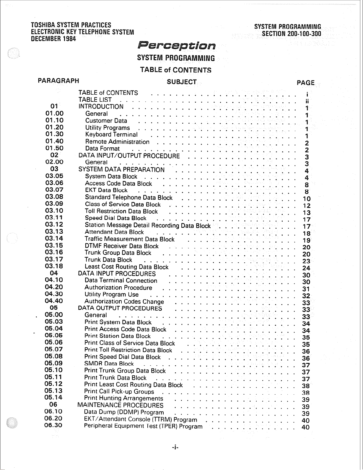
TOSHIBASY RACT
ONIC
LEPH
BER 1984
SYSTE
OGR ING
200
300
GE
01
01 .oo
01.10
01.20
01.30
01.40
01.50
02
03.08
03.08
03.10
03.11
03.12
03.13
03.1
03.1
03.1
03.17
04.20
04.30
04.40
05
. 05.0
05.0
05.04
- 05.05
05.06
05.07
05.08
05.09
05.10
05.11
05.12
05.1
05.1
06
06.10
06.20
06.30
TABLE of CONTENTS
TABLE LIST
INTRODUCTION ’ : : : : : : : : : : : : : : : : : : : : : : : : : : :
General
Customer Data
Utility Programs
Keyboard Terminal
Remote Administration
Data Format
DATA INPuT/~uTPu~PR~CEDURE~ 1 1 1 1 1 1 1 1 1 1 1 1 1 1 1 1 1 1
General
~Y~EIVI
System Data Block
Access Code Data Block
EKT Data Block
Standard Telephone Data*Blbck ’ : : : : : : : : : : : : : : : : : : : 1%
Class of Service Data Block
Toll Restriction Data Block
Speed Dial Data Block
Station Message Detail Recording Data’Biodk ’ : : : : : : : : : : : : : 17
Attendant Data Block .
Traffic Measurement Data Block’ ’ : : : : : : : : : : : : : : : 1 : : 19
DTMF Receiver Data Block
Trunk Group Data Block
Trunk Data Block
Least Cost Routing Data Block
DATAINPUTPROCEDURES ..:::::::::::::::::::
Data Terminal Connection
Authorization Procedure
Utility Program Use
Authorization Codes Change
DATA OUTPUT PROCEDURES
General
Print System Data Block
Print Access Code Data Block ’ : : : : : 1 : : : : : : : : : : : : : : 34
Print Station Data Block .
Print Class of Service Data Block’ * : : : : : : : : : : : : : : : : : : 35
Print Toll Restriction Data Block
Print Speed Dial Data Block
SMDR Data Block .
Print Trunk Group Data Block * : : : : : : : : : : : : : : : : : : : : 37
Print Trunk Data Block
Print Least Cost Routing Data Block
Print Call Pick-up Groups
Print Hunting Arrangements
MAINTENANCE PROCEDURES
Data Dump (DDMP) Program
EKT/Attendant Console (TERM) Program
Peripheral Equipment Test (TPER) Program
.............................
DATA PREPARATION . 1 1 1 1 1 1 1 1 1 1 1 1 1 1 1 1 1 1 1 1
.........
........................
..........................
..........................
........................ 1
.......................
.....................
.....................
.....................
... : : : : : : : : : : : : : : : : : : : : : : 23
.....................
......................
........................
....................
: : : : : : : : : : : : : : : : : : : : 33
...................
.....................
.......................
.................
......................
....................
....................
....................
...............
..............
i
ii
1
1
2
2
12
13
17
18
20
20
2
30
31
32
33
33
34
35
36
36
37
37
38
38
39
39
39
40
40
Page 78

ABLE
A
B
c
D
T
U
v
W
x
v
z
AA
AB
AC
LE
TTY & Modem Connections ....................
Utility Programs
Authorization Code Change
System Data Block
Access Code Data Block
Feature, Abbreviation & Code List
EKTDataBlock
EKT Key Assignments
EKT Directory Number
EKTPrivateCOLine
EKT Features
Standard Telephone data Block ’ 1 : : : : : : : 1 1 : 1 : : : : : : 1 :
Class of Service Data Block
COS Features & Codes
Toll Restriction Data Block
Speed Dialing Data Block . : 1 : : : 1 : : 1 : : 1 1 : 1 : : 1 : : : : 58
SMBR Data Block
Attendant Data Block’ ’ : : : : : : : : : : : 1 : : : 1 : : : : : : : :
Traffic Measurement
Traffic Measurement Report Format
Traffic Measurement Parameters
DTMF Receiver Data Block
Trunk Group Data Block
Trunk Group Data Block Entries
Trunk Data Block
Trunk Data Block Entries
Least Cost Routing Data Block ’ : : : : 1 : : : : : : : : : : : : : : : 69
Miscellaneous Parameters
AreaCodes ..........................
Area/Office Codes
Routes
Modify Digits ...
Print System Data Block
Print Access Code Data Block
Print Station Data Block .
Print Class of Service Data Block ’ : : : : : : : : : : : : : : : : : : : 75
Print Toll Restriction Data Block
Print Speed Dial List Data Block
Print SMDR Data Block
Print Trunk Group Data, Block’ * : : : : : : : : : : : : : : : : 1 : : : 77
Print Trunk Data Block .. ..
Print Least Cost Routing Data Block’ : : : : : : : : : : : 1‘ : : : : : : 78
Print Call Pick-up Groups
Print Hunting Arrangements
Data Dump Program
EKT Test Procedure
Attendant Console Test Procedure
Peripheral Equipment Diagnostic Procedure
Trunk Status Entries
Disk Drive Error Codes . : : : : : : : : : : : : : : : : : : : : : : : 87
...........................
......................
..................
...........................
.............
..............................
...................... 54
.......................
.........................
.................
...
......................
LossPlan
.......................... 68
........................
.....
.........................
.........................
.....................
.....................
. .
: : : : : : : : : : : : : : : : : : : : : : : 73
...................... 79
.....................
: : : : : : : : : : : 1 : : : : : : 64
...................
. . . . . . . .. . . . .. .
.................... 74
...................
...................
..................
::::::::l::::
.. . . .
..............
PAGE
50
51
51
51
66
56
E
61
62
62
64
65
67
69
70
..7 0
71
71
72
74
75
76
76
78
80
80
81
82
83
85
2
3
Page 79
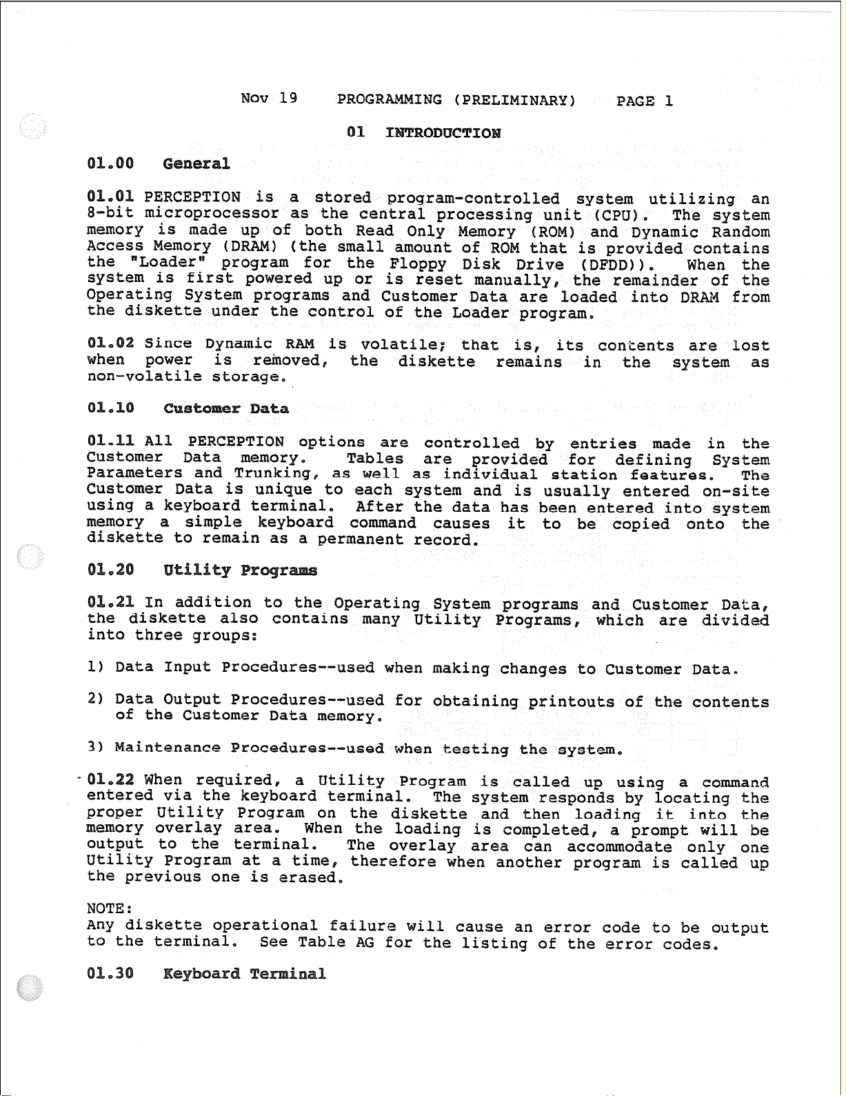
NOV 19 PROGRAMMING (PRELIMINARY)
PAGE 1
PERCEPTION is a stored program-controlled system utilizing
8-bit microprocessor as the central processing unit
(CPU),
The system
an
memory is made up of both Read Only Memory (ROM) and Dynamic Random
Access Memory (DRAM) (the small amount of ROM that is provided contains
the "Loader"
program for the Floppy Disk Drive (DFDD)).
When the
system is first powered up or is reset manually, the remainder of the
Operating System programs and Customer Data are loaded into DRAM from
the diskette under the control of the Loader program,
Since Dynamic R is volatile; that is,
the diskette remains in the
its contents are lost
system as
non-volatile storage.
All PERCEPTION options are controlled by entries made in the
mer Data memory.
Parameters and Trunking, as
Customer Data is unique to each
using a keyboard terminal.
memory a simple keyboard command
Tables
are provided for defining System
ell as individual station features, The
system and is usually entered on-site
After the data has been entered into system
causes
it to be copied onto the
diskette to remain as a permanent record.
In addition to the Operating System programs and Customer Data,
the diskette also contains many Utility Programs, which are divided
into three groups:
1) Data Input Procedures--
2) Data Output Procedures--
used when making changes to Customer Data-
used
for obtaining printouts of the contents
of the Customer Data memory.
3) Maintenance Procedures-When required,
a Utility Program is called up using a command
entered via the keyboard terminal,
used when testing the system.
The system responds by locating the
proper Utility Program on the diskette and then loading it into the
memory overlay area.
output to the terminal.
Utility Program at a time,
When the loading is completed, a prompt will be
The overlay area can accommodate only one
therefore when another program is called up
the previous one is erased.
NOTE:
Any diskette operational failure will cause an error code to be output
to the terminal,
See Table AG for the listing of the error codes.
Page 80

Nov 19
PRcGRAMMTNG(PRELIMINARY)
PAGE2
1 The PERCEZTION system. is designed to interface with standard
asynchronous keyboard/printer data terminals (aTexas Instrumntskdel
743
or
745,
or equivalent, is suitable).
An ELkcfxonic Industry
Association EIA) RS 232C-type data transmission interface is provided
systgn will support data speeds of 300 or 1200 bps,
The
connects to the TEw connector at them connector panel
pinassigmantsareshown inTableA).
utilizing a locally-provided mE%l, the
PEZQEMON system Utility
Programs canbe calledup, and the systemprcqrammj and tested frana
remote location vi
provided for the
ne line.
An EIA RS
a data speed of
300
232~
or
interface is
1200
bps is
SUppOlFtad.
The is comected to the
port pin assig
ts are s
amnector on the
Table A),
ThemEM and 'ITY connectors cannot be used simultaneously.
be "open" at any given time,
Utilizing one start bit,
one stop bit and one parity bit, the
comnunicates via the standard 7-level ASCII code on the TTY and
ports. The system transmits even parity and ignores parity on
the receive side,
one must
Page 81

(P
The Utility
are divided
1) Data Inplt
2)
Data outp
3)
ntcenance Pr
Each Utility Program has a
kdentify it and to call it up fr
mst be executed before a Utility Pr
The Utility
nits and the etablethats
DATAINPUTP-
UrdTelephoneDataBlcck
I..-'
‘,'
c
G
Page 82

(PRELmImRY)
the PEXEEIXON system data can be i
then listed on the System Record (
'11 thenserveasaprogramninggui
contains a .form for eat
by the Utility Program
e: System Data Block-DsYS Program).
ing data via a Utility Program is a matter of responding to the
ts are listed in their pr
spaceisprovidedtorecordarespo
ord forms to record the var
0
systan Data Rl
entries that are meaningful to
individual. station or trunk,
0 Data is entered as follows:
(Request)--1 cates programhasloaded. Since
only the response is possible:
in
ation record,,
order in the Sys
S
misCXl.1~
le rather
ta is
ions
11,
Record
ethe
pr-tb
DrzT (Daily Routine !FaskF-3pecifies
Linre specified
mter:
in r
KEI
themaintenance tobe run at the
T!E%f Wsnant Service+-Specifies if tenant service is Lo
calls, dial tOI calls, attZEZ%t I&al
11 be routed to the proper attendant console (Att.
. #1 for 3enant#l) according tm the response to
Data Block (DEKT Program), Standard Telephone
Block (IxMTprogram) andTrunkGroupData&Lock WIu?Program). If
entered, the attend&cmsoleswilloperateintheloadshaxingnrode,
ERter: Y (yes) or N (no),
Icp 1 (Intercept
the trunk group
ill be routed to
tone tOEL) or attendant
Enter:
ATT or OF%
--If the attendant takes control of a trunk grcup using
SC0
Intercep
feature, stations calling that trunk group
This entry defines ICP 1 as being overfl
NiT),'
ICP 2 (Inter
ily
::-/'4 f '!." /, ,
service and to
defines ICP 2 as being overfl
n night service
tone (OF%) or att
Page 83
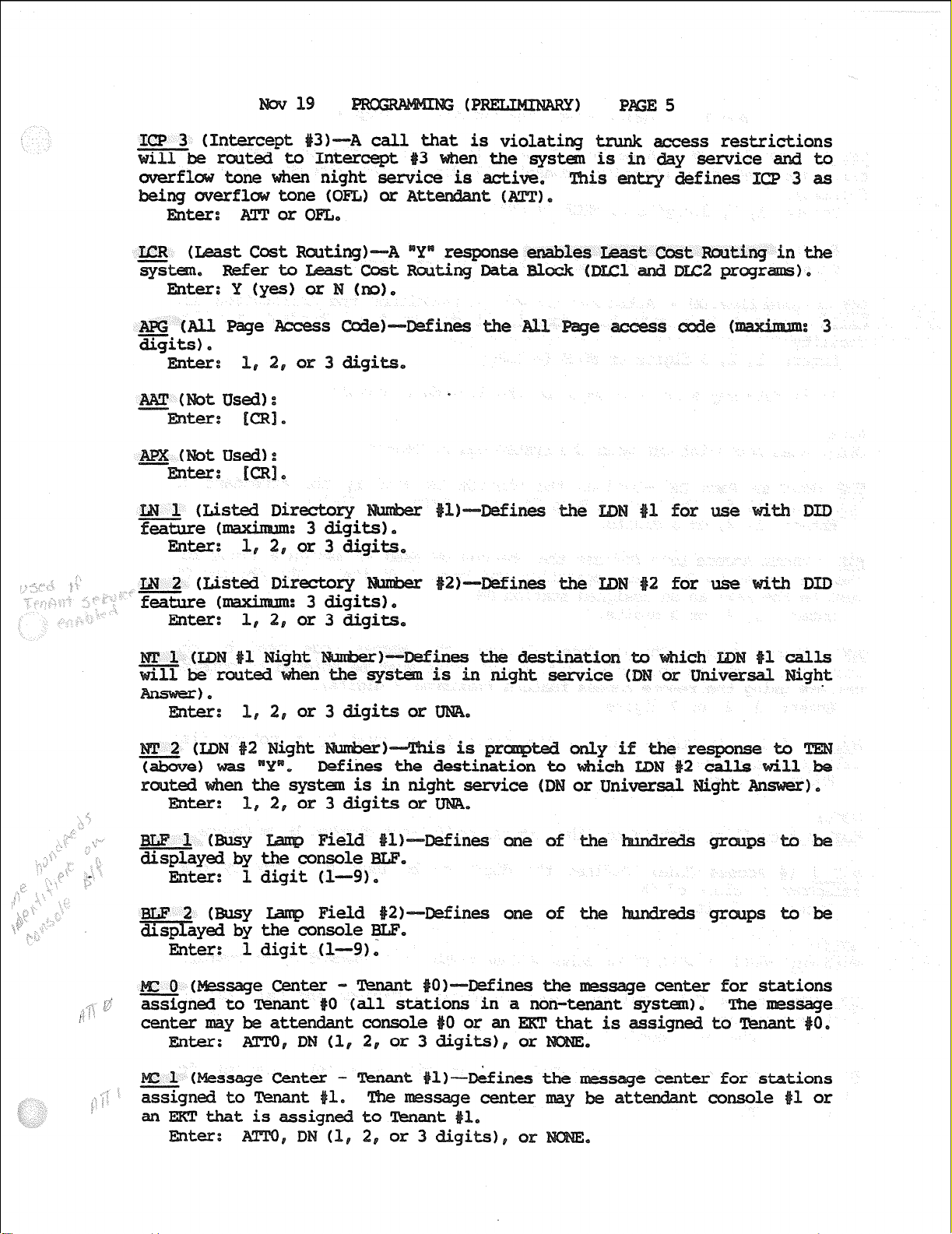
19
ES
lb- 1 for
(l--=9) *
EILF 2 msy
Field --Defines one of
dispr;;yed by mole
Enter: 1 digit (l-9);
2b-
ines
ines of
2
for use tb DID
or Universal.
Page 84
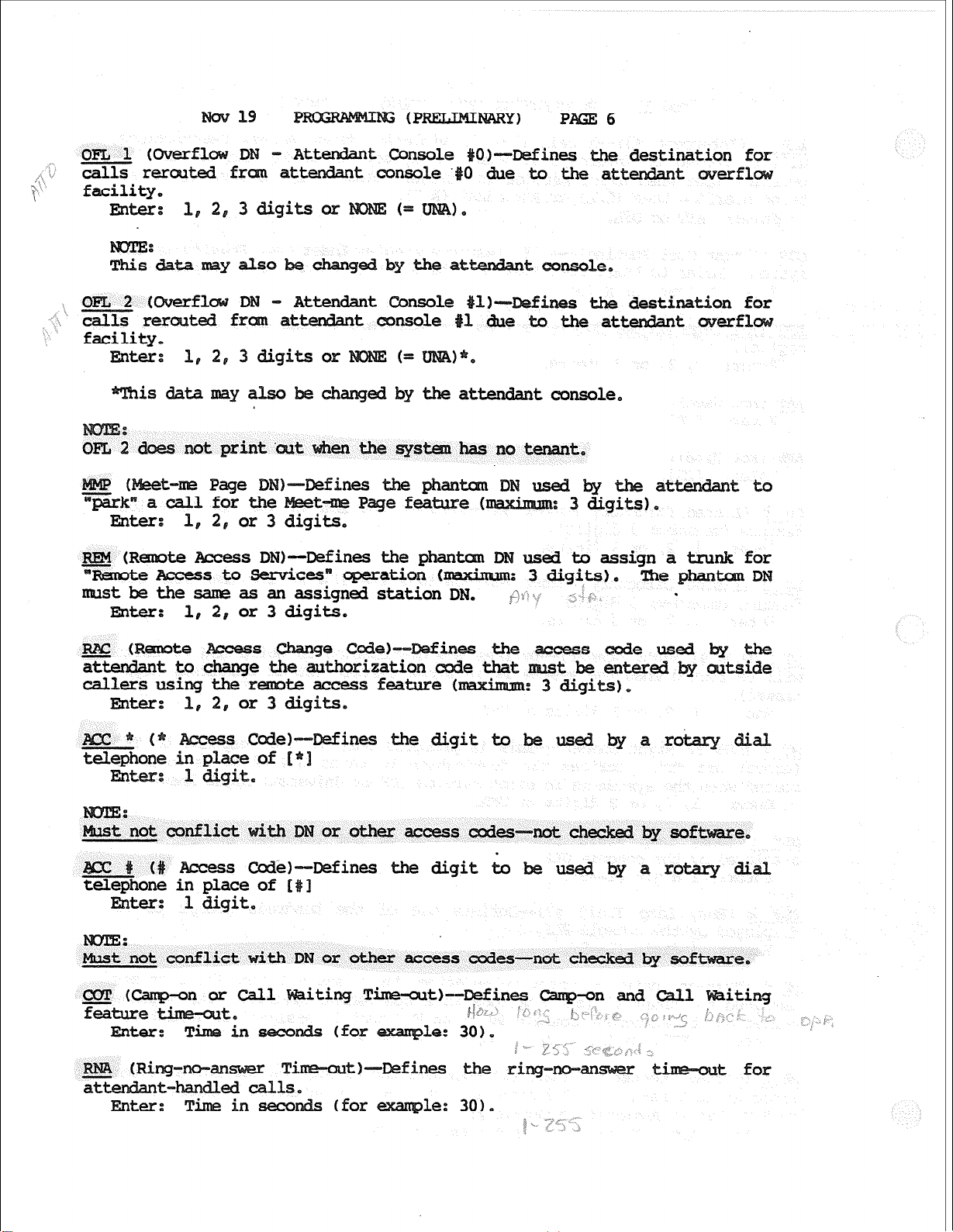
19
6
, 'i"<
i, ?
1‘
7
OFT.4 1 (
calls r
DN- Attendant Console
fran attef&nt console 1 due to the att t"
O)-Defines the
facility.
Enter: 1, 2, 3 digits or
t amiole,
ines the desti.fWzion for
facility.
Enter: 1, 2, 3 digits or
is datamaya attendant console.
not print the
Page DN tom DN used
for the
1, 2, or 3 digits.
Remte Access DNb--Defines the phantcxn DN used to assign a trunk for
teAccesst0 servicesn uperation 0mxim.m: 3 digits).
mSt be the sane as an assigned station DN. p.; ,, ‘:..
mter:
1, 2, or 3 digits,
erfl
tto
The phantmDN
.
(Recnote Access
:
ines
the digit to
ines the access
by-f
not conflict
Access Code) Defines
the digit Lo
in place of E
mter: 1 digit,
:
not conflict with DN or other access codes-not checked by
iting Time-outF-Defines
f f ; 0
j.i a/,*
(for
le: 30).
( .".
F--Defines the ri for
dial
e.
a r dial
Enter: Timeinseco
le: 301,
3 * " ‘7
(
Page 85

19
7
AOF (Attendant Overfl Time-cutb-Defines the
t for the at t
Overflow facility.
Enter: Time in seconds (for le: 301,
cm (Cal.1
Time-out)--Mines the
I*,. z:; :') __
Enter: The in seconds (for le: 12).
or
HID (Hold [500/25001 Tine out)--Defines the
out for the recall of a
before the
or a
hear
Enter:
Tik in seconds (for example: 15).
Also~cmntrols the release of an idle attendant console LPK key.
PBT U?ush-button Timz=-outf-Defines the
bemeen
Gits dialed on a trunk line fran a MMF t voice
path fromaMMFtelephoneto a00 line is brokendwbg dialing.
The PBT
timer determines quicklythepathis restoredand, therefore, shouldbe
as short as pass
Eater;
Tine in s&onds, e.g., 6,
LTd3 (tineLockout'@m&=--Defines the length of time that over tone is
apPlied to a station after having been released due to the timer.
After this timt, the station will hear nothinq.
EMer: Time in seconds, e,g.# 15.
UWmmatic CallbackReserve Time)--Defines the length of time that the
led station or trunk in an
call is reservedforthecaller ( :
6secmds),
Eater:
Tk in -&,
HFS (Handsfree Answerbck Station) --A Y" response all
eegep 3, /:e,/t-'.i /b" z ._)I“ - : *
calls frcm any
station to a Handsfree Answerback-equipped ,EKT to voice announce and be
replied to handsfree.
Enter: Y (yes) or N (no).
FB?A (Handsfree Answerback Attendant)--A
attendenttoaEl[andsfreeAnswerback-equipped~to
calls fr
anncxmce
replied, to handsfree.
and activates
response informs the sys
alarm on the console,
is to
Page 86
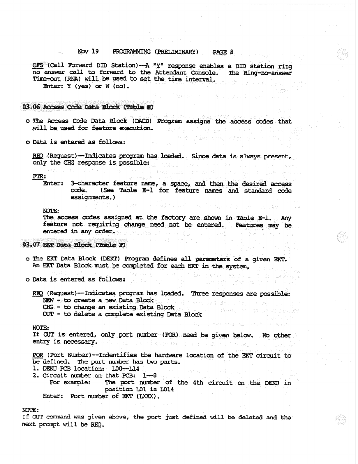
d DID Station)--+
response enables a DID station ri
w-
0
s Code Data Block (
used for feature execution,
0 Data is entered as fol
acter feature
(See Table E-
assig
:
WCXSS
feature not requiring change need not be entered.
entemdinanyorder,
Data is enter
ram
signs
assigned at the factory are
S
is
I?==&
desired access
Stan code
in Table E-l. Any
Features may be
.
is entered, only port
entryisnecessary,
b--1ndentifi
portnuxrber
1. DFXU l?CB location: LOO-Ll.4 '
0nthatFCB:
e, the port justdefin
e-e responses are sible:
location of .the ERT circuit to
th circuit on the DEXD in
Page 87

of Key Strips+-Informs the system of
s the EKT 11 have.
1 (for lo-key EKZ) or
_cos (classof Group 'ces+-Assigns one of the 16
of Service are defined using
(o--15),
P--AssignsEXTtooneofthe
f tenant service is not
of gr s of 10
0 orliftenantserviceis sel
-
i.R
stem
Block OSYS
= Y).
ines an inter
Qg (Cal.1 Forward to
tside the systemusing theCallForward-All calls feature
Enter:
Y or N.
n (Toll Restricted Class)--Assigns one of the ten classes of Toll
Restriction to the EKT.
Block UXQLprogram). Class 8 is sin-p
Oorlaredialedas the first or
Classes O--7 are definedin the Toll Restriction
toll res
seco
digit.
asunrestricted.
Enter:
response activates the
Y (yes) or N ho).
e activates the
D display on the
free
E (Key AssigmentsP-Assigns a DN or feature to one of the flexible keys.
Enter:
of the key to be defined
9 (or 19 for 20
fo
aspacebar. Keys
starting fran the
ip (the four keys
ing the key number
1 Feature or
ssible assig
nts
Directory (
Page 88

19 (
sc!RNNNxxx- Single Call Ring
0 Inmxning calls will ring Em.
= Directory (Station)
=FAmtrllmber=enterDNto
fordistributedhunt (see
Station Hunt - Distributed:
the hunt le:
X Onaxi&m: 8 stations
x = Distributed Hunt Gr
iv&e Co Lines:
eRing
ring EKT
oXXX=!L'DNas
1 10
S
e
e
Features:
e P=
isentered.
AC-AU i.cGdblback
ADL-Au ic Dialing
cm-CallForward-AllCalls
DIS DND- Do Not Disturb
PRS- Privacy Release
SCF-speakerRND- RepeatLas Dialed
SDS - SpeedDial-System
lfg 2 - Speed Dj."L-Stat+on (controller
VCF xxx - Voice Page (XXX=DNtobepaged)
FIX- Flash (sends flash toCOline)
W-Release
Display Date Tim&lap
of to
- Speed Dial-Station (user of lis
11 be repeated until lentries DEL
sig
Standard Telephone Data Block
iven conventional telephone.
h conventional telephone in the system.
Page 89

0 Data is entered as follows:
Wquest+-Indicates program has loaded, ee responses
-Tocreatea STT Data Blocky
-9Balter anexisting SlTData
- To delete a let; existing Data Block,
is enter&, only theport
snecessary,
location of the
ines thedirectory
1, 2 or 3 digits.
a station DN entered above also exists on an EKT that
e possible:
the DN does not exist on an
Classof Group F-4ssigns one of the 16 classes of
the telephone, (
pr
1
: ( l!5)*
+4ssigns the station tooneof the possible sys
ces are defined using
t:enants.
Enter:
TEIN = 'II),
(Call Pick-up GroupF4ssign.s the station to one of the 32
groups for use with the Call Pit feature.
Enter: Group number (O-311
tenant service is not selected in Syst
N) e
0 orliftenantserviceis selectedinSys Data Block DSYS
)-Defines the station to ich this DN hunts.
1 Fbrward-No Answer features,)
in hunt group,
b) Par Station Hunt - Distri
(N =
(X =
cl
sible
DLG (Dialing
station.
)--Defines the t of dialing, if
8 to
used by the
Page 90

19 (PmLIMmARY) E 12
Enter:DIP for dial pllse
IDN for DTkF.
MtG 0 or 1 for xnmml line (off-hook rings operator 0 or 1).
for hot line (off-
Dial ListF-Assigns
one of 25
sonal, lo-number
dial
the station a controller of
s the station a user of list
-
~~ -
A (
ning Wne All
k--Defines an interruption-protected station. An
Nn response will prevent warning tones from being applied to the station.
Enter: Y or N.
Calls feature
TOL (Toll Restriction C%aSSk-Assigns one of the ten classes of 3311
ZZriction to the station. Classes O--7 are defined in the Toll
RestrictionDataBlock (M0L PrograM.
restricting when 0 or 1 are dialed as the first or second digit,
Class 8 is siqle toll restriction:
None
defines the stations asunrestricted.
mter:
O-8 or None.
asses of
COS are
ess rkstrxted
mthisDataBlock.
0
DC0S program assigns a (O--15) to each gr of restrictions to
The number defin ereisthenentered to the 00s
tin theDSTT, DEXTandIYIGPprograms.
o Any numbers not entered or otherwise defined
restrictions.
0 Data is entered as follows:
k?Q (Request)--Indicates program has 1
ed, Theonlyresponsepossibleis
EiZ.
s (Class of !Service)--Defines the COS nun&r (O--15) and the restrictions
to be associated with it.
The possible restrictions are listed in Table
H-l.
Enter: COS number,
foil
by the restriction, in the following
format: 0 Too OVR Ace,
In this example, COS 0
trunk group 00,
and attendant control override.
cos:
Repeat for all COS entries.
erride
Page 91

0
ogram defines the office
Toll Restri
on feature.
0
eight classes of ml1 Restricti
needs in defining a station8s
udes specific restricti
code table. Fbr convenience,
. tables.
0
is entered as follows:
o--I cates
(Sub TYPE
program,
PAR-
ram type>--
ee responses arepossible:
sce.ll~eousParametersTable:
entifies system operating parameters.
cxs- F&krictionClassTable:
ines theeachclass of Toll~es
- Area/Office Code Exception Table:
Defines an exception to the dialing privil
the CIE area code table.
e are
*
ee rams thin
on.
specified
available
le is
Since each sub-program can be entered in
separated by the
fol
CodeF-Defines the ar
used when analyzing di
codee
Da~enteredherewill appearin~eastco&~~~~ting~ataBlock (DICK
programPARtable,HAC
Enter:
Area Code N
O/
ICC (Interchangeable Codesk--A
codes are used.
Interchangeable
the secondd
ently for the
ich
not
contaming an area
that interchangeable
that have 0 orlas
Pr
teach
Page 92
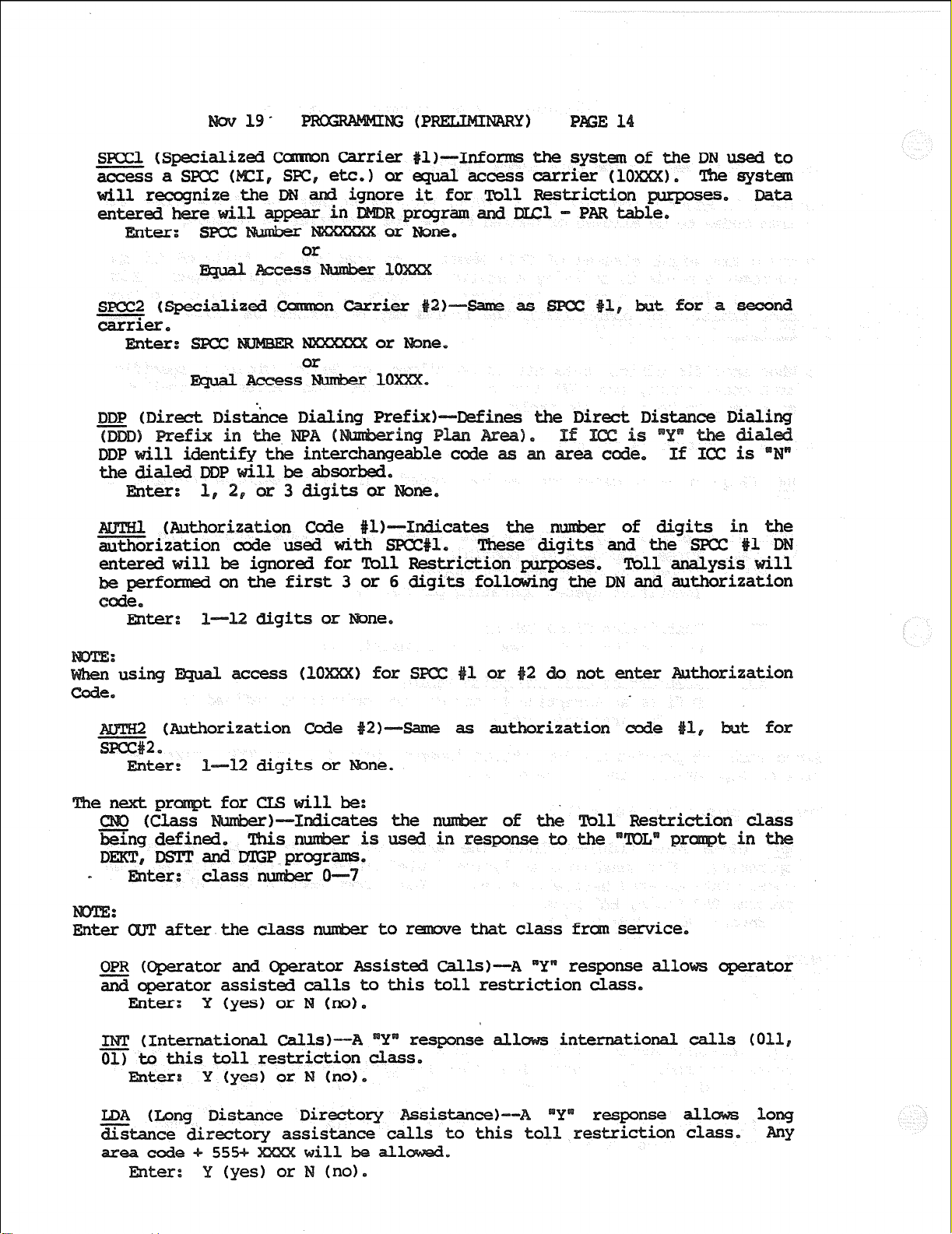
(P
CcmonCarrier
, SIX, etc.) cc access carrier (10
or
t
carrier.
Enter:
(Authorization Code #lb-Xndicat
ization code used with SPCC#l,
enter&will be ignored for lbll Restri
formed on the first 3 or 6 digits fol ng the DN and authorization
Informs the system
1 Restriction
Dxcl-PAR
for
: l--12 digits or
:
usi
access (10 1 for s
not enter orization
.
(Authorization Code
as authorization for
P=--12 digits or
of Tbll Restriction cl
m response to the
t in
DSlTandDXGPprograms.
class
after the class
nuxber O-7
to r ethatclass fr service,
OPR (Operator and Operator Assisted Cal&)---A Yw response all0 operator
operator assisted calls to this toll restriction class.
Einter: Y (yes) or N (no).
(Xntemational Calls)--44 response all
international calls (011,
01) to this toll restr
Enter:
Y (yes) or
Enter:
Distance Directory Assistance+-A
to this toll restriction
response 1
Page 93

Table of this toll
all area codes ose deleted in
in
or denied for
deleted (D) as
(Office Code Table
i&ion Class as an
for this Toll Restri
to add office ax&s.
D
to delete office
ines the Office
those deleted
etc.
2209
2316
office codes
220-229
231-236
Page 94

19
e:
es cannot be ed and deleted in the
separatepassisrequiredforeachstep,
NARY) E 16
s gh the table,
The next pr
t for
11 be :
ea Code
(class F-Defines the toll. restri
that are subject to this exception table,
nmximumof al18maybeentered.
0 If a toll restriction class table (CLS) is al.1
1, all office codes within that specified area code will be
except those specific office codes sdded below in the OFC
0 If a &ll restriction class 1 is not all to dial an
irty (32) area/office
table is assi
any one area
s (O---7)
of classes, up to
to dial an area
OFC (Office
ice codes that are assigned to this
Office codes may be added (A) or
deleted (D) as single 3 digit c
3 digit office codes.
ere the first 2 digits are
ntoallcodes inthisr
range* cove.r to 10
are entered usi digit
third 'digit represents the start point of the range (frm) for
digit of the office code: the fourth digit represents
range (to)
it of the office code. See
Eider: etc,
to add office cod-,
D
ii& t-XXX etc.
to delete office codes,
office codes
220--229
2316 231--236
e; the
the last
the
e
Page 95

19
E 17
cannot be added and deleted
separate pass is required for each s
DialDataElock (DSDL)
Speed Dial-System list
Al.1 of thes
0
catesprogramhasl
-tochangeexistingorenter
of the list to
(00 = systa List)
(Ol--25 =
was entered in respod to RIQ above, no other data is
required.
Station List)
Bass
cugh
le.
le:
isrequeststhe
ted as one of the 16 digi
0
Detail Recording Data El
andtypeofcallstobe
a
0 Data is entered as follows:
(Requestb--Indicates
program has 1
- tocreatea new table
- to alter existing data
- to clear all existing data
CodelLexqth)--Defines length of
access code,
for dial tone delay.
1 defines the
f
ee responses are possible:
is
is
trunk QrsuP
used or no
of digits to
used (l--12),
Page 96
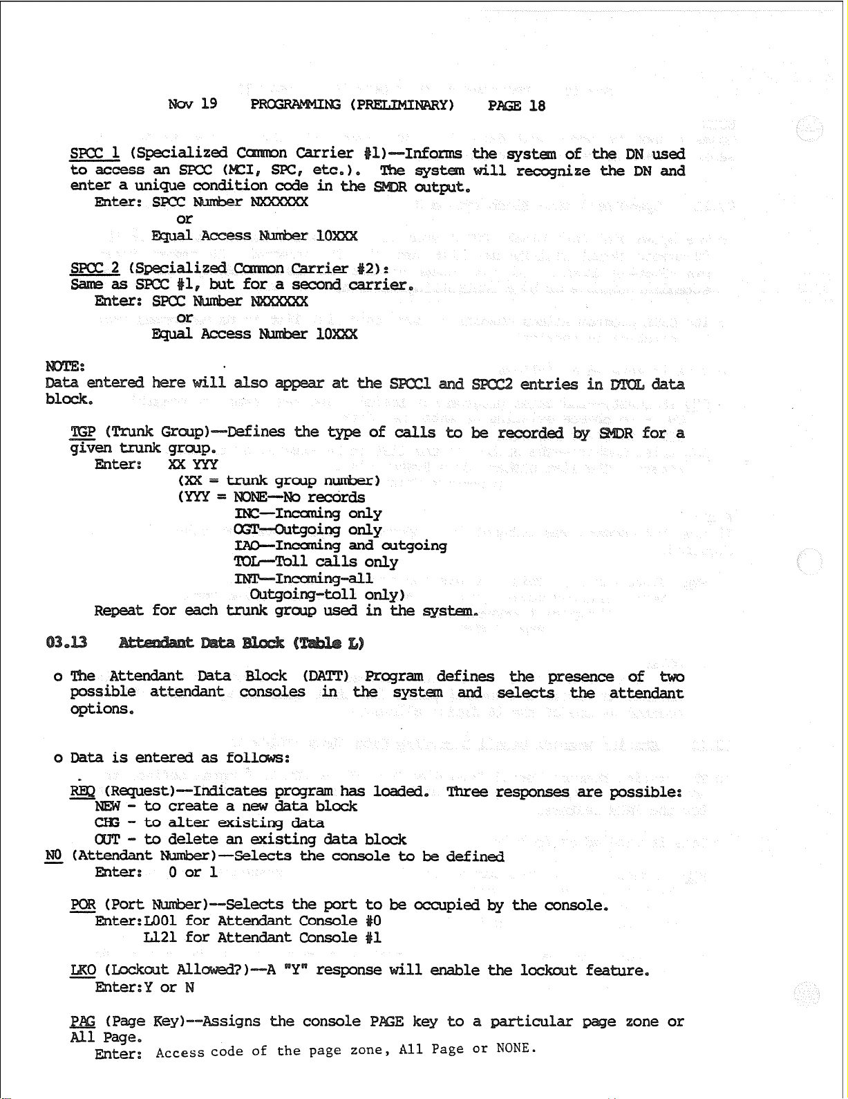
19
18
SKY21 GQ3cial.ized of DN used
to access an spcc ( nize DN and
condition code in
oG!P-Outgoing only
IAO-Incuning
and
outgoing
mll callsonly
for each trunk gr usedintbe
0
Attendant Data Block UXTT)
sible attendant consoles in
options.
0
is entered as folP
tP--Indicates progr
Tbreeresponses arepossible:
create a newdata
cK;- to alter existing data
an!-
NO G4ttendantNumber)-Selects theconsoletobedefined
-
to delete an existing data block
Enter: Oorl
rP--Selects theport
be occupied by the console.
or Attendant Console
IL21 for Attendant Console
Eater:
le the
signs the console
Access code of the page zone, All Page or NONE.
1
iculax
t feature.
one or
Page 97

ov 19
PRoG~kwkwG (PREMLIMINIARY) PAGE 19
0 The
affic surattent Data I3lock
that control theTrafficb4easurement
entered after each
(System Timme)--Ree the
rtunity
ime: HHMMSS
for a change.
(24
hour clock), QT CR (no change)
defines the
is given in response to
(Start Date)--Defines the te for record
reporting. Ou
Enter:start Dat
ts current data andgives an nity for a change,
t or CR (no change)
(Start Time)--Defines the s time for record
and reporting. Outputs currentdataandgives an
Einter:Start Time: JBMMSS, or CR (no change)
RPT (Report Parameters):
-SYST (systein Data)
(Attendant 0)
ATT1
(Attendant
1)
T13poo (TrunJc Group 00)
1
PlYrunk Group 01)
15
S@l&S
e parameters that are t
current (Y or N) is output for
given
for a change.
/j
Page 98

19
(PRECLIMIMY) 20
mter:Y (yes) or N (no) Poll
quipped in the system
is entered, no
mxt -)--selects the po
j?O.TZtn~haStWOparts:
1) DRCU PCB location (ROO)
2)Circuitnu&erontheDRCUPCB(1-6)
Enter:
Port 8smbe.r to b? used (ROOl-RO06)
by a CR for each p=arameter.
ogram identifies ich
ich can
ee responses are sible:
receivers
receiver,
(Repeat until all circuits are assigned)
0 Data is entered as follows:
9 (Request)-Indicates program has 1
NEW-Tocreateanewtrunkgroup
CHG - Toalterdatainanexisting DataBlock
GUT- To delete an entire existing Data Block
NCYES:
1. All trunks t be deleted frcm the group using the
csmand will be accepted
ed, on.lytheTmnkGroup entered*
tais necessary.
GRP vITn.lnk Gr
)--Identifies the
response given to
ed, Threerespo~arepossible:
Pw3==
Page 99

TEN Plknant
I=---Indentifies the
belongs.
Enter: Tenant OOXTl
tto
ich the. trunk gr
FJXUnk
)--Identifies' the of
A not possible to enter a change (
Blockmustbedeleted (CWT)
ter:
TIE
-TIETrunk
Line
oingk--
service.
Enter:
-Inccmingorily
-0utgoing only
-2-way
STp (Advance Step)--Identifies
svce. If a station user at
are all busy, a trunk from the group identified in
ed.
TrunkGxwp
11
next trunk group in a route*
tstoaccessatnmkinthis
(O--15) oK
XXXSS
ttedi
for the
g==P.
czonflict tsin
f 30 or 300 is used as an access
Enter: AccessCode (1,2or 3digi.W
ass of Service)
(O--151
VI!txnanission)--Wines
The entry made here will
switching done on trunk connecti
the transmission ar
Table O-2 for loss plan).
required for the
the type of PAD
Enter: WiC: Non-transmission ted (2-wire circuit with < 2dB
loss)
re
(
circuit or
re VNL circuit)
Sezrt
used by the
Page 100
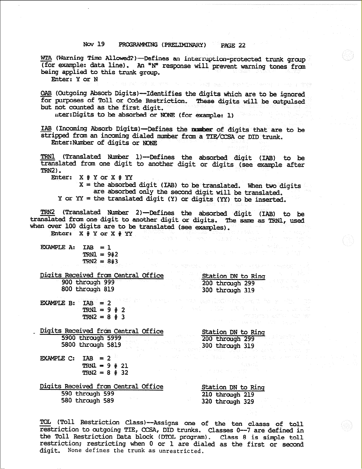
EMer:Yor
E 22
es an in
response
Absorb Digits)--Identifies the digits
ses of Toll or Cede Restriction,
sl
1.
Eater:
YOK
TRN2
VJbsnslated
iiixted frcmonedigi
wer 100 digits are
Enter:
LEA: IAB =1
= 9#2
= 8#3
irst digi
sorbed or
(for
t
) translat
digit (!?Zr digits (YY) to
2)--D@fineS
absorbed digit (IAB) Lo
another digit
be translated (seeexanples).
ch are to be
!Blesameas
ignored
S&
to
gits
I used
Diqits Received frcm Central Office
900 thrcugh 999
800 through 819 300 through 319
_ Digits Received frcm Central Office
5900 through 5999
5800 through 5819
LEC: IAB =2
TRN2=8#32
Diqits Received frm
Central
Office
590 through 599
580 through 589
(Toll Restriction
on to
Rk?StX
restriction; res
digit.
None defines the trunk
as
one of & M
are dialed as the first
unrestricted.
Station DN to Ring
200 through 299
Station DN to 200 Rinq
through 299
300
ough 319
Station DN to Rinq
210 through 219
320 through 329
classes o--
1. Class 8 1"
or second
1
 Loading...