

Page 1
-------------
-----‘-y
I-III--
1-1-1-1-1-1-1
.
w-1-1
.
.
--
A.,
IA.
-
-
c
L
I
!’
Page 2
ATTENDANT CONSOLE
Address Code
10
11
12
13
14
15
16
17
18
19
.
4.
43
20
21
22
23
24
25
26
27
28
29
30
31
32
33
34
35
36
37
38
39
40
41
42
44
45
46
47
48
49
50
51
52
53
54
I’
Name
Phone Number
1
1
1
1
1
\
;
W
E
P
t
1
1
E
1
1
1
1
1
,
P
cn
Page 3
TOSHIBA
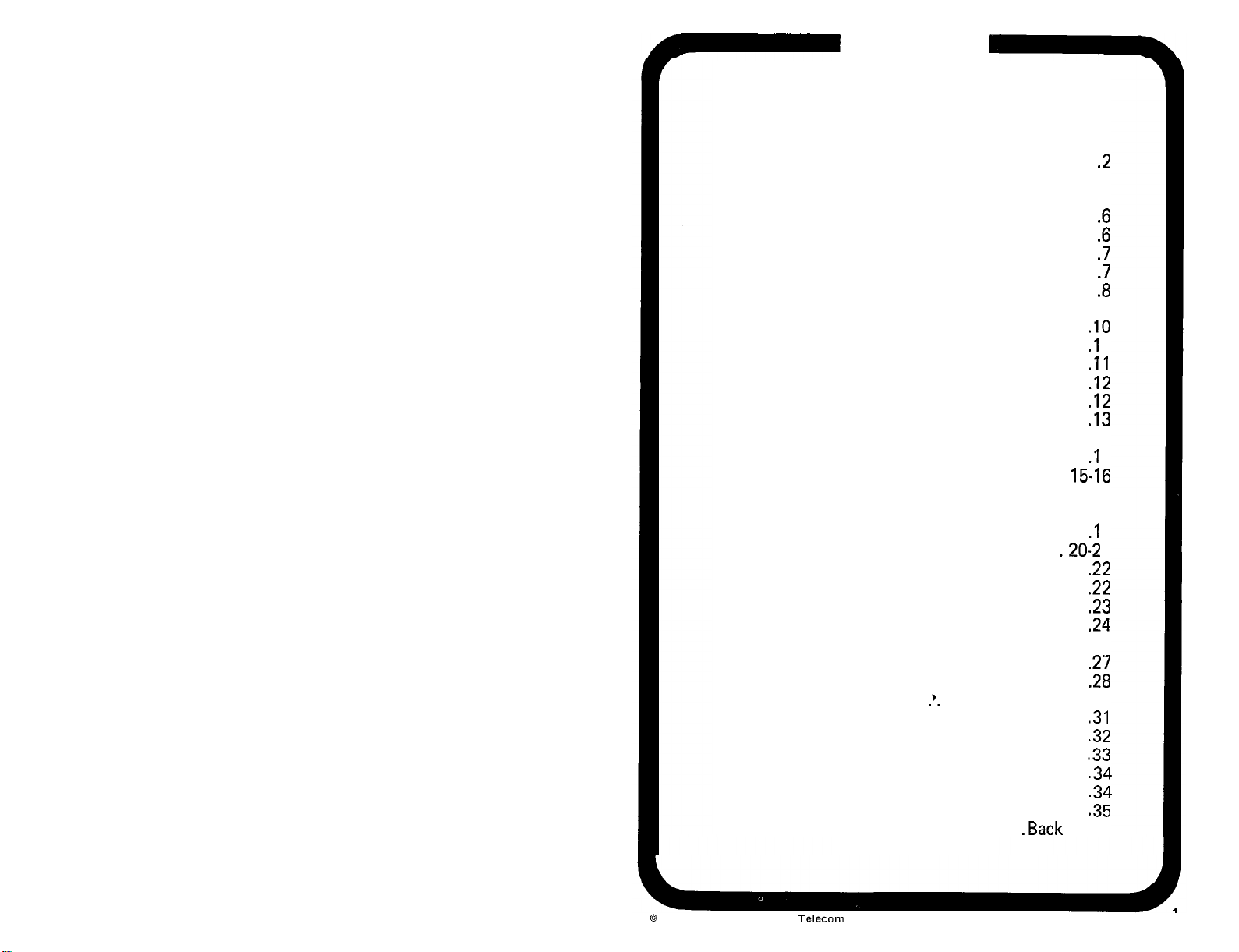
TABLE OF CONTENTS
Introduction
Console Display Panel.
Console Keyboard.
Volume Control
Handset/Headset.
Emergency Switches
Answering An Incoming Call
Extending A Call To An Idle Directory Number.
..............................
..................... 2-4
.......................
...........................
..........................
........................
..................
.4-6
..
Extending A Call To A Busy Directory Number. . 8-9
Timed Recall
Attendant Recall.
Calling An Outside Number.
.............................
.........................
.................
Calling A Directory Number. ................
Holding A Call On An LPK Key ..............
Through Dialing
Trunk-To-Trunk Call
Serial Call
Exclusion Keys (Splitting).
Verify
Paging
................................
................................
Meet-Me-Page
..........................
.....................
...............................
................
............................
Attendant Conference. ..................
Overflow.
Position Busy
Join Key
Activating Night Service
Night Answering Connections.
Remote Access To System Services.
Speed Dialing-System
Trunk Control. ..........
...............................
............................
................................
....................
.............
...........
......................
.*.
............ .29-30
Account Number Recording .................
Message Waiting.
Display and Set Date/Time
Cancel All Call Forwarding.
System Initialize
Emergency Transfer
Phone Directory
..........................
..................
.................
..........................
.......................
...................
.Back
.lO
.I
.11
.I2
.I2
.I3
13-14
.I
15-16
16-18
18-19
.I
.20-2
.22
.22
.23
.24
25-26
.27
.28
.31
.32
.33
.34
.34
.35
Cover
.2
.6
.6
.7
.7
.8
1
5
9
1
0
Copyright 1983 Toshiba
Telecom
I
Page 4
INTRODUCTION
EMERGENCYTRANSFER
Your PERCEPTION attendant console has been
designed to provide easy access to the wide range
of features offered by your Toshiba telephone
system. The console is equipped with a Display
Panel, Keyboard, Volume Control, and either a
handset or headset. A detailed description of the
console features and operations is found in the
following text.
CONSOLE DISPLAY PANEL
The console display panel includes a Busy Lamp
Field and the following displays: Incoming Call
Identification, Calling Source Number, Class of
Service, Call Destination Number, and Call
Destination Status.
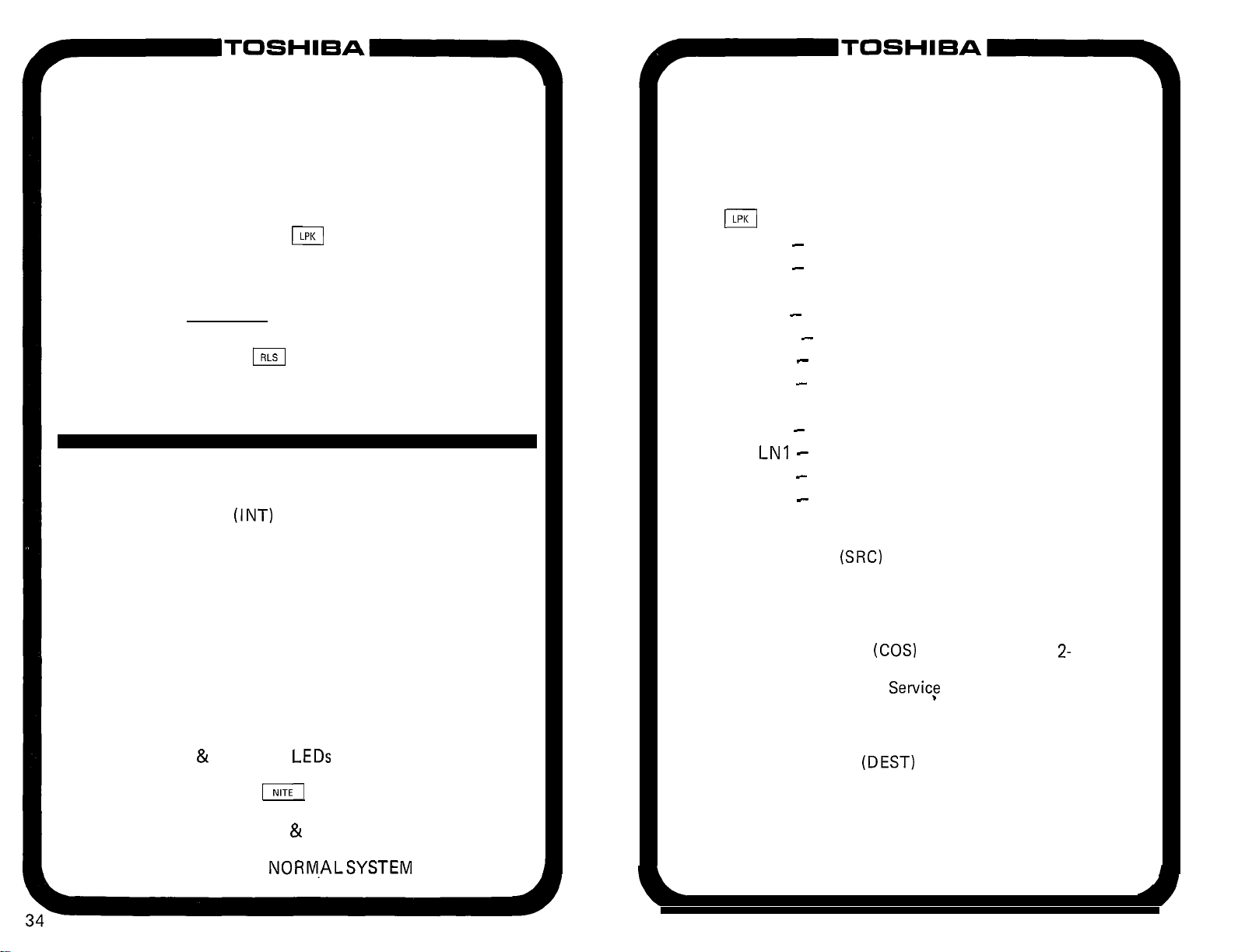
If the system goes completely out of service and
the MAJOR ALARM lamp is not on, the Emergency
Transfer switch (located on the underside of the
console on the side nearest the dial pad) can be used
to manually set the system into Emergency Transfer
operation. Operating the switch will disconnect
existing calls and connect the designated stations
directly to the outside lines.
TO OPERATE THE EMERGENCY TRANSFER
DEPRESS THE
l MAJOR ALARM LED lights
TO RESTORE NORMAL OPERATION
DEPRESS THE
l MAJOR ALARM LED goes off
m
(EMTI
BUTTON
BUTTON
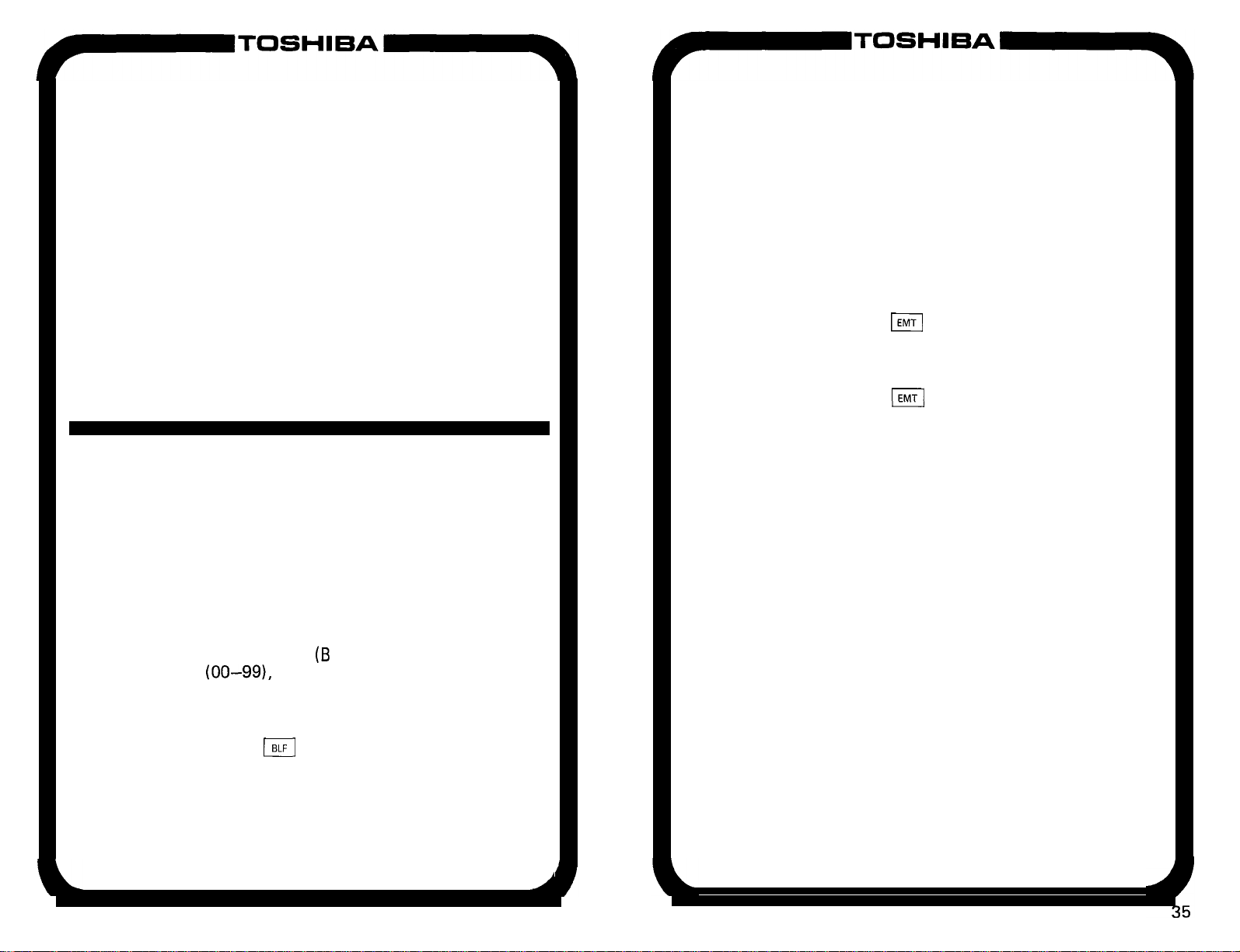
BUSY LAMP FIELD
The Busy Lamp Field (B LF) displays 100 2-digit
numbers
“hundreds group” identifier that shows which
group is currently being displayed. The display
alternates between groups in response to
operations of the
the console).
(00-99),
and is equipped with a
m
key (located on the face of
(continued)
A
Page 5
CANCEL ALL CALL FORWARDING
CONSOLE DISPLAY PANEL (continued)
It is possible for the Attendant Console to cancel
all Call Forwarding arrangements set up by station
users.
TO CANCEL ALL CALL FORWARDING
1. DEPRESS AN IDLE
l R LS LED goes off
m
KEY
. LPK LED lights
2. DIAL THE CALL FORWARDING CANCEL
CODE
l All CFD arrangements are cancelled
3. DEPRESSTHE
l LPK LED, all displays go off
l RLS LED lights
l Console becomes idle
m
KEY
SYSTEM INITIALIZE
The Initialize
underside of the console is used to reset system logic
in the event of a system malfunction. This switch
should be used prior to resorting to the Emergency
Transfer switch.
WARNING:
This switch should be used only in extreme situations
as it will cause all calls in the system to be dropped.
TO INITIALIZE THE SYSTEM
1. DEPRESS THE INT SWITCH
l MAJ LED lights momentarily
l RLS LED goes off
l NITE
l MIN LED lights
2. DEPRESSTHE
l System switches to DAY operation
3. SET SYSTEM TIME & DATE
l MIN LED goes off
4. PROCEED WITH
(INT)
&
POS BSY
switch located on the
LEDs
light
m
KEY
NORM.ALSYSTEM
OPERATIONS
INCOMING CALL IDENTIFICATION
The Incoming Call Identification (ICI) display
is a backlighted panel that indicates the type of
call that is currently connected to a console Loop
B
key. Twelve different displays are possible:
TIE - Tie Trunk
CO - CO trunk
WAT- WATS trunk
FX - Foreign exchange trunk
OPR - Dial “0” call
RCL - Recall
SER - Serial call
HLD- Held call recall
TIM - Timed reminder (Camp-on, RNA, etc.)
LNI -
DID call to listed directory number 1
LN2 - DID call to listed directory number 2
INT - Intercept
CALLING SOURCE NUMBER
The Source
(SRC)
display is a 3-character,
7-segment LED display that gives the attendant the
number of the calling station or trunk.
CLASS OF SERVICE
Class of Service
(COS)
is displayed as a
2-
character, 7-segment LED display, giving the
attendant the Class of
Servicf
of the calling station
or trunk.
CALL DESTINATION NUMBER
The Destination
(DEST)
display is a 3-character,
7-segment LED display showing the station or
trunk called by the attendant.
(continued)
A
Page 6
CONSOLE DISPLAY PANEL
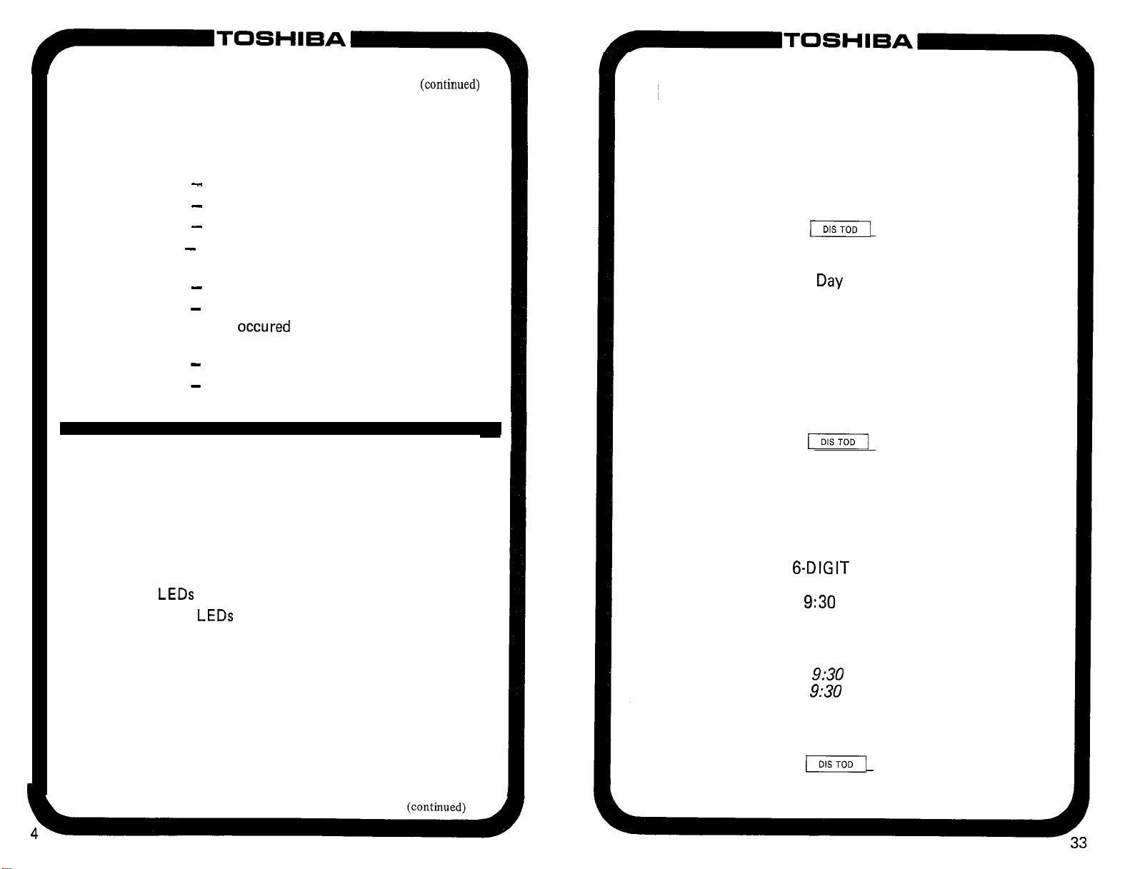
CALL DESTINATION STATUS
The status (STATUS) display is a backlighted
panel which indicates the status of the called station
or trunk. Eight different displays are possible:
RNG
BSY- Called station is busy
DND
FWD - Called station is forwarded to the
RST
HNT- Called station was busy and hunting
VCT- Called number does not exist or isdisabled
TLK
-
Called station is ringing
-
Called station is in Do Not Disturb mode
number now displayed as DEST
-
Attempted connection is not allowed
has
occured
displayed as DEST
-
Attendant is in a voice connection with
the called party
to the number now
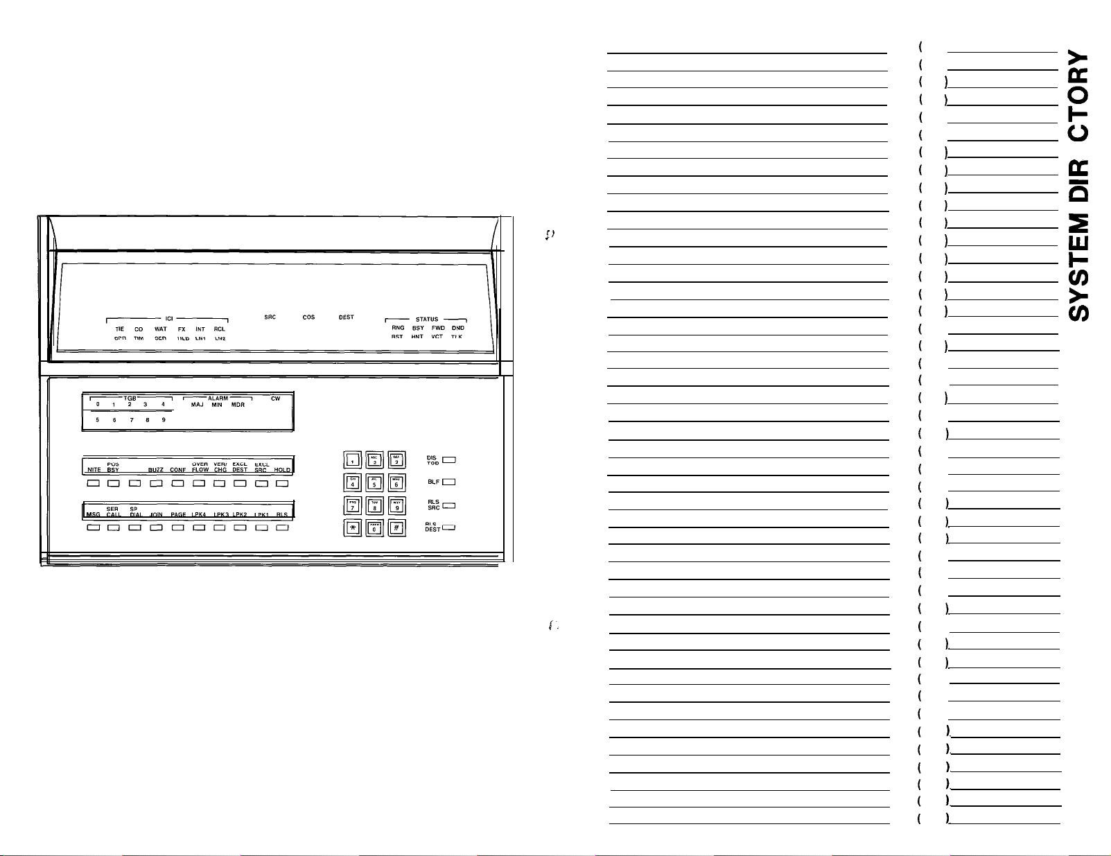
CONSOLE KEYBOARD
The console keyboard design includes a display
window, two horizontal rows of 10 keys each, a
12-key dial pad, and a vertical row of four keys.
The faceplate display window houses the following
displays:
Trunk Group Busy (TGB) provides 10 numbered
LEDs
to indicate the status of trunk groups O-9.
ALARM
Call Waiting (CW) LED indicates that an
LEDs
for MAJOR, MINOR and TAPE:
MAJOR: Alarm occurs when the system is
not functional and is accompanied
by an emergency transfer.
Ml NOR : Alarm indicates system clock is
not set or ringing power failure
MDR:
unanswered call is waiting for the attendant.
Alarm indicates a problem with
external SMDR equipment.
(continued)
DISPLAY and SET DATE/TIME
Your telephone system has an internal clock that
must be set to the correct date and time in order for
features such as Traffic Measurement and Station
Message Detail Recording to be effective.
TO DISPLAY DATE
DEPRESSTHE
l The date is then displayed:
SRC cos
Month
TO SET DATE
ENTER THE 6-DIGIT DATE (via the dial pad)
IN THE FOLLOWING FORMAT: MMDDYY
e.g. For January 1, 1983, enter 010183
l The new date will appear in the display
TO DISPLAY TIME
DEPRESSTHE
TIME
l The time is then displayed:
SRC
Hours Minutes
TO SET TIME
ENTER THE
IN THE FOLLOWING FORMAT: HHMMSS
e.g. For
l The new time will appear in the display
The time is displayed and ‘entered in the 24-hour
clock form (for any hour after 12 noon, add 12)
TO START THE CLOCK AND CLEAR THE
DISPLAY
DEPRESSTHE
l Display clears
71
Day
(
cos DEST
6-DIGIT
9:30
e.g.
TIME (via the dial pad)
AM, enter 093000
9:30
AM is 0930
9:30
PM is 2130
(-1
KEY
DEST
Year
KEY A SECOND
Seconds
KEY A THIRD TIME
Page 7

rToSH’=A-
MESSAGE WAITING
If your console is designated as the Message
Center, you may indicate to the called station that
a message is waiting.
TO LEAVE A MESSAGE WAITING SIGNAL
1. PROCESS THE CALL IN THE NORMAL
MANNER
2. IF BUSY OR NO ANSWER:
l DEPRESS THE
l MSG LED lights
l MW indication is set
l DEPRESSTHE
l DEST &STATUS displays go off
3. PROCEED AS NORMAL CALL
TO CANCEL MESSAGE WAITING
1. DEPRESS AN IDLE
l RLS LED goes off
l LPK LED lights
2. DIAL STATION DIRECTORY NUMBER
l DEST is displayed as digits are dialed
l MSG LED shows status of MW of called station
(i.e., if MW is active on that station, the LED
will be on)
3. DEPRESSTHE
l MSG LED goes off (if it was on)
l MW condition is cleared at called station
TO CANCEL& MESSAGE WAITING SIGNALS
1. DEPRESS AN IDLE
l RLS LED goes off
l LPK LED goes on
2. DIAL “ALL CLEAR” ACCESS CODE
l All MW conditions in the system are cancelled
3. DEPRESSTHE
l LPK LED goes off
l RLS LED lights
m
m
m
m
m
KEY
m
KEY
KEY
KEY
KEY
KEY
CONSOLE KEYBOARD
(conthed)
The lower horizontal row of keys are all equipped
with
LEDsand
MSG :
(reading from left to right) are labeled:
Activates Message Waiting feature if
console is designated as Message Center
SER CALL: Activates the Serial Call feature
SP DIAL: Activates the Speed Dial-System feature
JOIN: Connects two parties which have reached
the attendant on two different
m
PAGE: Provides the attendant with a direct,
push-to-talk access to one paging zone
or All Page
LPK 1-4: The four Loop Keys are used for
answering and originating calls
RLS:
Releases the console from any connection
The upper horizontal row of keys, with the exception
of the HOLD key, are all equipped with
LEDs
and
(reading from left to right) are labeled:
NITE:
Activates the Fixed, Flexible and
Universal Night Answering features
POS BSY: Used to “busy out” one position of a
2-console system
SPARE: Reserved for future use
BUZZ:
Allows the attendant to select whether
or not a signal tone will be heard during
a Call Waiting condition
CONF: Activates an attendant conference (up to
six parties including the attendant console)
OVE RF LOW: Transfers waiting calls to an alternate
answering point
VER/CRG:
Overrides a’busy station, trunk or a
Do Not Disturb condition. It is also used
to record an account number when
extending a call
EXCL DEST: Excludes the destination party
from a 3-way conversation
EXCL SRC: Excludes the source party from a
3-way conversation
HOLD:
Holds calls connected to Loop keys
keys
Page 8

CONSOLE KEYBOARD
(continued)
ACCOUNT NUMBER RECORDING
The dial pad is of the standard 1 Z-key alpha-numeric
configuration and is used to dial both internal and
outgoing calls from the console.
The four keys in the vertical row on the right of the
console are not equipped with
LEDs,
and are labeled
(from top to bottom) :
DIS TOD: Displays the time and date from the
system clock. While being displayed
the clock can be corrected
BLF: Used to alternate between the
“hundreds groups” displayed on the
console
RLS SRC: Disconnects the source party from a
Loop key
RLS DEST: Disconnects the destination party
from a Loop key
VOLUME CONTROL
A volume control for the console tone signal
is located on the rear of the console below the Busy
Lamp Field housing.
Your system automatically records the details
of some or all of the calls you make to or receive
from outside the system. Recorded calls may be
assigned account numbers for billing purposes
(
digits). Perform the following before
extending the call:
TO RECORD AN ACCOUNT NUMBER
1. START FROM A NORMAL VOICE
CONNECTION
l LPK LED on
l ICI, SRC displays on
2. DEPRESS THE
l Connection on hold
l
VER/CRG
(
LED lights
KEY
3. DIAL ACCOUNT NUMBER ON THE DIAL PAD
(
l When number is complete:
l
l Talking connection reestablished
digits)
VER/CRG
LED goes off
4. PROCESS THE CALL NORMALLY
HANDSET/HEADSET
Your console may be used with either a handset
or headset (whichever is the most comfortable and
convenient for you to use), which may be plugged
in on either side of the unit. Also, the handset cradle
may be mounted on either side of the console.
,
Page 9

TRUNK CONTROL
(continued)
EMERGENCY SWITCHES
TO PASS A TRUNK TO A STATION
1. DEPRESS AN IDLE
l RLS LED goes off
l LPK LED lights
m
KEY
2. DIAL STATION NUMBER
l DEST displays station number
l STATUS displays RNG
3. STATION ANSWERS
l STATUS changes to TLK
4. DIAL THE TRUNK ACCESS CODE
l SRC displays station number
l COS displays station COS
l DEST displays trunk access code and number
l EXCL SRC lights
l Receive trunk dial tone
5. DEPRESSTHE
l RLS LED lights
l LPK
l Station is free to dial on trunk
&
EXCL SRC
TO RELEASE TRUNK CONTROL
m
KEY
LEDs
and all displays go off
(TGB
1. DEPRESS AN IDLE (KEY
l R LS LED goes off
l LPK LED lights
2. DIAL m
mm
, FOLLOWED BY THE
TRUNK ACCESS CODE
l TGB LED goes off
l Control is released
3. DEPRESSTHE
l RLS LED lights
l LPK LED goes off
m
KEY
LED is on)
Two switches are located on the underside of
the console. These switches are for emergency use
only and are labeled as follows:
EMT: The Emergency Transfer switch allows the
attendant to set the EMT circuits manually
in the event of a system malfunction.
INT:
The Initialize switch is used to reset the
system logic in the event of a system
malfunction.
CONSOLE OPERATION
ANSWERING AN INCOMING CALL
1.
YOU WILL HEAR AN INCOMING CALL
SIGNAL
l ICI lights and SRC is displayed
l LPK LED flashes
2.
DEPRESS THE APPROPRIATE
l LPK LED lights
l Signalling stops
3.
YOU ARE CONNECTED TO THE CALL
l Make an appropriate response
m
KEY
Page 10

EXTENDING A CALL TO AN
IDLE DIRECTORY NUMBER
1. DIAL THE DIRECTORY NUMBER
l EXCL SRC LED lights steadily when first
digit is dialed
l Voice path to caller is broken
l DEST is displayed as digits are dialed
l STATUS displays RNG
l You hear ring tone
2. DEPRESS
l LPK LED, all displays go off
l RLS LED lights
l Console becomes idle
l Caller hears ring tone
1
KEY
NOTE:
1) If
you wish to announce the call, wait for the
called party to answer before depressing the
m
key.
2) If the call remains unanswered after (
seconds, the call will be returned to your console
as a Timed Recall.
EXTENDING A CALL TO A BUSY
DIRECTORY NUMBER
(With Camp-on/Call Waiting)
1. DIAL THE DIRECTORY NUMBER
l EXCL SRC LED lights steadily when first
digit is dialed
l Voice path to the caller is broken
l DEST is displayed as digits are dialed
l STATUS displays BSY
l If you hear nothing (Camp-on), go to Step 2
l If you hear ring tone (Call Waiting), go to
Step 4A
l If you hear busy tone, go to Step 3B (it
indicates that Camp-on/Call Waiting is not
possible for one of the following reasons) :
TRUNK CONTROL
Your console allows you to control access to any
trunk group for the purpose of allocating special
facilities. When you have taken control of a trunk
group, a station user trying to access that group
will be routed to your console (ICI displays OPR).
(In some systems a few executive stations will be
allowed to override your control.) The caller’s name
should be listed to be called when a trunk is available.
TO TAKE CONTROL OF A TRUNK GROUP
1. DEPRESS AN IDLE
l LPK LED lights
l
R
LS LED goes off
2.
DIAL
RR T;;I
TRUNK ACCESS CODE
.TGB
(trunk group busy) LED lights
l Control is in effect
I
3. DEPRESS THE
l RLS LED lights
l LPK LED, all displays go off
IF A STATION USER CALLS A CONTROLLED
TRUNK
1. STATION DIALS ACCESS CODE
l Console signals
l LPK LED flashes
l ICI lights
l SRC and COS are displayed
2. DEPRESS THE APPROPRIATE
l LPK LED lights
l Voice connection is established with caller
If a trunk is available, proceed as in ‘*Through
Dialing/:
name and station for a callback and then release.
If no trunk is available, take the caller’s
m
KEY
, FOLLOWED BY THE
m
KEY
m
KEY
B
(continued)
A
(continued)
Page 11

SPEED DIALING-SYSTEM
Speed dialing allows you and other extension
users to use a 2 - digit code in place of a full
telephone number when making calls. The Speed
Dial-System list of telephone numbers must be stored
via the attendant console, but, once stored, all
numbers are accessible to all extensions. A maximum
of 90 telephone numbers may be stored.
TO MAKE A CALL WITH SPEED DIAL-SYSTEM
1. DEPRESS AN IDLE
l RLS LED goes off
l LPK LED lights
2. DEPRESSTHE
3.
DIAL THE 2-DIGIT ADDRESS CODE FOR THE
TELEPHONE NUMBER YOU WISH TO CALL
*The
system will dial the number for you
TO STORE A NUMBER
1.
DEPRESS THE
an
a
key)
l The SP DIAL LED flashes
2. DIAL:
a) The 2 - digit code (10 through 99) you wish
to associate with the telephone number
b)
The trunk access code
c)
The
q
allow time for trunk dial tone to appear)
d)
The telephone number
3.
DEPRESS THE
The SP DIAL LED goes off
The code and telephone number are stored
m
KEY
71
71
KEY
KEY (do not depress
key (this inserts a 3-second pause to
r-==l
KEY AGAIN
EXTENDING A CALL TO A BUSY
DIRECTORY NUMBER
a) Another call is previously in Camp-on/
Call Waiting (only one is allowed per
station).
b)
Camp-on/Call Waiting is not permitted due
to system restrictions (called station is
dialing or in a conference call).
2. DEPRESSTHE
l EXCL DEST LED lights
l EXCL SRC LED goes off
l You have a voice connection with the caller
3A. IF THE CALLER WISHES TO WAIT
4A. DEPRESS THE
l LPK LED, all displays go off
l RLS LED lights
l Console becomes idle
If the call remains unanswered for
the call will be returned to your console as a Timed
Recall.
3B. IF THE CALLER DOES NOT WISH TO WAIT
OR IF NO CAMP-ON IS ALLOWED
4B. DEPRESSTHE
l Called station is released from console
l DEST display is cleared
l Another DN can be dialed if requested
5B. DEPRESSTHE
l LPK LED, all displays go off
l RLS LED lights
l Console becomes idle ,
m
a
m
m
KEY
KEY
KEY
(continued)
KEY
(
I
seconds,
Page 12

TIMED RECALL
REMOTE ACCESS TO SYSTEM
If an extended call remains unanswered for
(
) seconds, the call will be returned to
your console.
1. YOU WILL HEAR AN INCOMING CALL
SIGNAL
l ICI lights (TIM); SRC and DEST are displayed
l LPK LED flashes
l STATUS is displayed:
RNG for ring - no answer
BSY for Camp-on, Call Waiting
2. DEPRESS THE APPROPRIATE
l LPK LED lights
l Signalling stops
m
KEY
3. YOU ARE CONNECTED TO THE CALL
l Make an appropriate response
4A. IF THE CALLING PARTY (SRC) WISHES
TO WAIT
5A.
DEPRESS THE
l LPK LED, all displays go off
l RLS LED lights
l Console becomes idle
4B. IF THE CALLING PARTY
m
KEY
(SRC)
DOES NOT
WISH TO WAIT
5B. DEPRESSTHE
l DEST, STATUS displays go off
l Called station is released
l Another DN can be dialed, if requested
6B. DEPRESSTHE
l LPK LED, all displays go off
l RLS LED lights
l Console becomes idle
-1
m
KEY
KEY
SERVICES
This feature allows a user outside of your system
to access the system services via an exchange network
connection. The user dials a preselected exchange
number to connect to your system and then dials
a 3-digit authorization code. The user may then make
a call just as it is done from inside the system normally.
The authorization code used by the outside user
is controlled by the Attendant Console and may be
changed anytime.
The trunk(s) used for this service (and, therefore,
the exchange number dialed by the outside user)
may be permanently fixed or may be assigned by
your console each time it is needed (it is a
programmable option). In addition, the trunks may
be arranged (by system programming) to operate in
the Remote Access mode in both DAY and
service or N ITE service only.
TO ASSIGN OR CHANGE THE AUTHORIZATION
CODE
1. DEPRESS AN IDLE
l
R
LS LED goes off
l LPK LED lights
2. DIAL THE ACCESS CODE
3. DIAL THE AUTHORIZATION CODE
4. DEPRESS THE
l LPK LED goes off
l RLS LED lights
l Console becomes idle
m
m
KEY
KEY
TO SELECT TRUNK(S) TO BE USED WITH
REMOTE ACCESS TO SYSTEM
Process as in Night Answer Connections using the
number as the directory number. All trunks
assigned to this number will function in the Remote
Access to System mode. System programming will
determine if Remote Access is functional in both
DAY and
NITE
service or
NITE
service only.
NITE
Page 13

P-TOSHIBA
ITOSnlBAY
NIGHT ANSWERING CONNECTIONS
(continued)
UNIVERSAL NIGHT ANSWERING
1. DEPRESS AN IDLE
l LPK LED lights
l RLS LED goes off
2. DEPRESSTHE
l
NITE
LED flashes
l Receive dial tone
3. DIALTHETRUNKACCESSCODE FOLLOWED
BY ITS EQUIPMENT NUMBER
l Dial tone stops when the first digit is dialed
l First two digits are displayed as DEST, but
shift to SRC when the number is completed
l LPK LED goes dark and dial tone returns
when the number is completed
If a non-existent access code or trunk equipment
number is dialed, you will hear the overflow tone.
Depress the
71
4. DEPRESSTHE
l RLS LED lights
. NITE, LPK
LEDs
Repeat above steps to make additional assignments.
m
KEY
m
KEY
key and redial.
m
KEY
go off
ATTENDANT RECALL
A station user, while talking to another party, may
recall the console for the purpose of asking the attendant
to take a message or to “park” the call on a busy station.
1. YOU WILL HEAR AN INCOMING CALL
SIGNAL
l ICI lights
l LPK LED flashes
2. DEPRESS THE APPROPRIATE
l LPK LED lights steadily
l EXCL SRC LED lights
l Signal stops
l STATUS displays
l You have a voice connection with the DEST party,
(RCL),SRC,
ILK
COS,
DESTaredisplayed
m
KEY
SRC party is separated from the conversation
3.
DEPRESS THE
l The DEST party (recalling party) is disconnected
l You have a voice connection with the SRC party
@=-!
KEY
4. PROCESS IN THE SAME MANNER AS A
NEWLY ANSWERED CALL
CALLING AN OUTSIDE NUMBER
1. DEPRESS AN IDLE
l RLS LED goes off
l LPK LED lights
2. DIAL THE DESIRED TRUNK ACCESS CODE
l DEST displays trunk number, STATUS
displays TLK
l Receive trunk dial
3. DIAL THE DESIRED NUMBER
4. DEPRESS THE
THE CALL
l LPK LED, all displays go off
l RLS LED lights
l Console becomes idle
NOTE:
To extend the call to a station, depress the
proceed to dial the station DN in the usual way.
m
KEY
ton,e
m
KEY TO TERMINATE
m
and
Page 14

-TosH’=A-
CALLING A DIRECTORY NUMBER
1. DEPRESS AN IDLE
l RLS LED goes off
l LPK LED lights
2.
DIALTHE
l DEST is displayed as the digits are dialed
DIRECTORY NUMBER
3A. IF THE DIRECTORY NUMBER IS BUSY
l STATUS displays BSY
l You hear busy tone
3B. IF THE DIRECTORY NUMBER IS IDLE
l STATUS displays RNG
l You hear ring tone
l Party answers
l STATUS changes to TLK
l You have a voice connection with called party
4. DEPRESS THE
THE CALL
l LPK LED, all displays go off
l RLS LED lights
l Console becomes idle
HOLDING A CALL ON AN
In some cases you may wish to hold a call on an
key while you gather more information or page someone.
DEPRESS THE
l LPK LED winks
l RLS LED lights
l All displays off
l Calling/Called party on hold hears MOH, if equipped
*You
are free to originate or answer calls on
other
m
keys
TO RECONNECT
DEPRESS THE APPROPRIATE
l LPK LED lights
l RLS LED goes off
l ICI, SRC, COS, DEST, STATUS displays on
l You have a voice connection with the SRC
m
KEY
m
KEY TO TERMINATE
Ej
KEY
m
lLPKl
KEY
KEY
m
NIGHT ANSWERING CONNECTIONS
Night connection assignments are stored in system
memory. Set-up is required only upon initial
installation or when changes are required. Flexible
night answering allows any number of trunks to be
assigned to the same station. Any trunks not assigned
a night station will cause the Universal Night Answer
(UNA)
signal to be activated.
FLEXIBLE NIGHT ANSWER
1. DEPRESS AN IDLE
l LPK LED lights
l R LS LED goes off
2. DEPRESSTHE
l
NITE
LED flashes
l Receive dial tone
3. DIALTHETRUNKACCESSCODE FOLLOWED
BY ITS EQUIPMENT NUMBER
l Dial tone stops when the first digit is dialed
l First two digits are displayed as DEST, but
shift to SRC when the number is completed
l LPK LED goes dark and dial tone returns
when the number is completed
If a non-existent access code or trunk equipment
number is dialed, you will hear the overflow tone.
Depress the
m
4. DIAL THE DIRECTORY NUMBER
l Dial tone stops after the first digit
l DN is displayed as DEST
l LPK LED lights
l Receive dial tone
REPEAT STEPS 3 and 4 to make additional
5.
assignments
6. DEPRESSTHE
l RLS LED lights
l NITE, LPK
LEDs
If a non-existent DN is dialed, you will hear the
overflow tone. Depress the
redial.
m
KEY
m
KEY
key and redial.
,
m
KEY
go off
-1
(DN)
key and
Page 15

p-TOSHIBAI-q
ACTIVATING NIGHT SERVICE
All LPK keys must be idle before activating this
feature; use single or multiple console instructions
(depending upon your system’s design).
SINGLE CONSOLE
TO ACTIVATE NIGHT SERVICE
1. DEPRESS EITHER THE
KEY
l
NITE
and POS BSY
l All existing Night Service selections are activated
l RLS LED goes off
2. UNPLUG THE HANDSET/HEADSET
l Console keyboard is removed from service
TO CANCEL NIGHT SERVICE
1. PLUG IN THE HANDSET/HEADSET
l Console keyboard is activated
l
NITE
and POS BSY
l RLS LED lights
l System is in Day Service
MULTIPLE CONSOLES
TO ACTIVATE NIGHT SERVICE
j..
DEPRESS EITHER THE
KEY
a) If the other console is still active:
l POS BSY LED lights
l Your console is removed from service
b)
If the other console is already in POS BSY:
l
NITE
and POS BSY
l System is in Night Service, all existing Night
Service selections are activated
2. UNPLUG THE HANDSET/HEADSET
l Console keyboard is removed from service
TO CANCEL NIGHT SERVICE
1. PLUG IN HANDSET/HEADSET
l Console keyboard is activated
l
NITE
and POS BSY
l RLS LED lights
l System is in Day Service
m
LEDs
LEDs
m
LEDs
LEDs
OR
light
go off
OR
light
go off
m
m
THROUGH DIALING
Requests may be received from stations or tie
line users for dialing access to numbers or trunks
from which they are restricted.
1. YOU WILL HEAR AN INCOMING CALL
SIGNAL
l ICI lights
l LPK LED flashes
2. DEPRESS THE APPROPRIATE
l LPK LED lights steadily
l Signal stops
l You have a voice connection with the calling
(S
RC) party
(OPR),
SRC, COS are displayed
m
KEY
3. DIAL THE DESIRED TRUNK ACCESS CODE
l EXCL SRC LED lights steadily
l STATUS displays TLK
l Voice connection with the calling party is
broken
l Receive trunk dial tone
4. DEPRESS THE
m
KEY TO TERMINATE
THE CALL
. RLS LED lights
.The
calling
(SRC)
station may dial on the
selected trunk
TRUNK-TO-TRUNK CALL
A call from outside the system that has been
answered at your console can be connected to an
outgoing line.
1. DIAL THE DESIRED TRUNK ACCESS CODE
l EXCL SRC LED lights
l Outgoing trunk number is displayed as DEST
l STATUS displays TLK
l Receive trunk dial tone
2. DIAL THE DIRECTORY NUMBER
Page 16

TRUNK-TO-TRUNK
3. DEPRESSTHE
l RLS LED lights
l All displays go off
l LPK LED goes off or winks (LPK on hold)
m
KEY
CALL
(continued)
depending on the type of trunk involved in
the connection
Some types of trunk lines give no signal when the
distant party disconnects, and this makes automatic
release of a trunk-to-trunk connection impossible.
If
you attempt to establish a connection between
two such trunks, the connection will be made but the
call will remain on the L PK in a “hold” condition.
You will be required to enter the call periodically
to verify its status and, ultimately, to disconnect it.
4. TO RE-ENTER A TRUNK-TO-TRUNK CALL
5. DEPRESSTHE
l LPK LED lights steadily
l ICI, SRC, DEST, STATUS displays on
l A 3-way conversation is established
m
KEY
6A. IF THE CONVERSATION IS STILL IN
PROGRESS
7A. DEPRESS THE
l RLS LED lights
l All displays go off
l LPK LED winks (LPK on hold)
m
KEY
6B. IF THE CALL HAS BEEN COMPLETED
7B. DEPRESSTHE
l DEST is disconnected
l DEST, STATUS displays go off
8B. DEPRESS THE
m
m
KEY
KEY TO TERMINATE
THE CALL
l LPK LED, all displays go off
l RLS LED lights
l Console becomes idle
JOIN KEY
The
I/
key allows you to connect one LPK
line with another LPK line. In a typical operation; a
call has returned to your console unanswered on LPK
#I,
and the called party must be paged.
1.
DEPRESS THE
l LPK
l Caller is put on hold
l RLS LED lights
#I
2. PAGE CALLED PARTY
3. CALLED PARTY CALLS ATTENDANT
l LPK
l R LS LED goes off
l ICI, STATUS, COS are displayed
#2
4. DEPRESS
CALL
l LPK
5.
I
NFORM PARTY #2 OF THE CALL ON LPK
6.
C
IEPRESS
l ICI, STATUS, COS displays go off
l LPK
7.
C
IEPRESS m
l LPK
l LPK
l ICI, SRC, COS
#2
THE
#2
#2
#I
original call on LPK
l DEST displays DN from LPK
l STATUS displays TLK
l A 3-way conversation is established
8. DEPRESSTHE
l LPK
l RLS LED lights
l The two parties remain connected
#I
m
KEY
LED winks
LED flashes
m
KEY #2 TO ANSWER THE
LED lights
m
KEY
goes on hold
KEY
#I
LED goes off
LED changes from wink to steady
LEDs
light and identify the
#I
#2
m
KEY
LED, all displays go off
#l
Page 17

TOSHIBA’-
OVERFLOW
When your console becomes very busy,. it is
possible to divert calls that have been
unanswered for over (
)
seconds to an
wartmg
alternate answering point. Substituting “0” for the
trunk access code and equipment number, designate
the alternate answering point using the Night
Answering Connections instructions.
TO ENGAGE OVERFLOW
DEPRESSTHE
[q
KEY
. OVFL LED lights
l Overflow is engaged
TO RELEASE OVERFLOW
DEPRESSTHE
l OVFL LED goes off
l Overflow is disengaged
)
KEY
POSITION BUSY
The
m
console “busy”, preventing additional incoming calls
from being assigned to your console. Calls will be
djverted to the second console in the system.
If onlv one console is
the
[posBsyj
the
(
key.
TO USE POSITION BUSY
DEPRESSTHE
l If only one console is in the system (or the
other console is in POS BSY), the POS BSY
and
NITE LEDs
Service)
l If the other console is active in the system,
POS BSY LED lights
TO RELEASE POSITION BUSY
DEPRESSTHE
l POS BSY LED goes off
l
NITE
l Your console is now active
key allows you to make your
eauioDed
in
vour svstem.
key will have the same effect as
)I
KEY
light (system is in Night
m
KEY
LED goes off (if it was on)
SERIAL CALL
FOR AN INCOMING CALL THAT REQUESTS
TWO OR MORE STATIONS
1. DEPRESSTHE
[m
KEY
2. DIAL THE FIRST STATION NUMBER AND
EXTEND CALL USING NORMAL
PROCEDURES
When the call is completed and the station user
hangs up, the call will be returned to your console
with an ICI display of SER. Repeat above steps if a
third station is required, otherwise process as a
normal call.
EXCLUSION
I
Use of the Exclusion (
keys enables you to split a three-way connection and
KEYS (SPLIT TIN G)
1
and
m
)
allows you to converse privately with either the
“source” or “destination” party. When you are
involved in a 3-way connection, it is possible to:
a) Talk privately with the called party (DEST)
b)
Talk privately with the calling party (SRC)
c) Form a 3-way voice connection consisting of
yourself, and both the calling and called
parties
TO TALK TO THE CALLED PARTY PRIVATELY
DEPRESSTHE
l EXCL SRC LED lights
l You may talk to the called party privately,
I-
(ExcludeSource)
KEY
the calling party cannot hear you
The Exclude Source condition activates au
toma ticall y
when you start dialing to extend a call
/.
. .
:
:-.
,‘.
:
!.
‘,
Page 18

EXCLUSION KEYS (SPLITTING)
(continued)
TO TALK TO THE CALLING PARTY PRIVATELY
DEPRESS THE
Key
l EXCL DEST LED lights
l You may talk to the calling party privately,
the called party cannot hear you
TO FORM A
EITHER AN EXCL SRC OR EXCL DEST
CONDITION
DEPRESS THE APPROPRIATE
l EXCL SRC or EXCL DEST LED will go off
l You and the other two parties may converse
freely
TO RELEASE A CALL WHILE IN ANY OF THE
ABOVE CONDITIONS (connecting the calling and
called parties)
DEPRESS THE
l LPK LED, all displays go off
l RLS LED lights
l SRC and DEST parties are connected
3-WAY
m
(
(Exclude Destination)
CONVERSATION FROM
m
KEY
KEY
ATTENDANT CONFERENCE
(continued)
TO RELEASE FROM CONFERENCE
6. DEPRESSTHE
l CONF LED changes to steady
l LPK LED goes off
l RLS LED lights
l Console is idle
0
Conference continues
m
KEY
TO RECALL THE CONSOLE BY A CONFEREE
(station user)
7. STATION USER FLASHES THE HOOKSWITCH
OR DEPRESSES
0
Console signals
l LPK LED flashes
l CONF LED flashes
8. DEPRESS THE APPROPRIATE
0
Signal stops
l LPK and CONF
*Console and recalling party have a voice
connection
l Remaining conferees continue to conference
9. PROCEED FROM STEP 4
m
KEY ON EKT
LEDs
change to steady
m
KEY
VERIFY
The Verify feature enables you to ascertain the
status of a station or trunk to determine if a problem
exists or to interrupt a call in an emergency situation.
TO VERIFY STATION STATUS
1. DEPRESS AN IDLE
l LPK LED lights
2. DEPRESSTHE
l VER/CRG LED lights
3. DIAL THE STATION NUMBER
l DEST displays the station number
m
KEY
mVER/CRG
KEY
TO REENTER THE CONFERENCE
You can reenter the existing conference, if
required. A warning tone will be inserted into the
conference before you are connected.
10. DEPRESS AN IDLE
l RLS LED goes off
l LPK LED lights
11. PROCEED FROM STEP 1
m
KEY
*
Page 19

ATTENDANT CONFERENCE
You can set up a conference call for as many as
five people (including a maximum of two trunk lines)
plus yourself, at the request of either a station user
or an outside caller. The starting point for a
conference can be any of the following conditions:
a) Console has answered an incoming call from
a station or trunk and that party is to be the
first member of the conference
b)
Console dials the first conference member
on an
c)
Due to an Attendant Recall, the console has
a
attendant must establish a 3-way voice
connection through a second operation of the
m
TO CONFERENCE
1. DEPRESSTHE
l CONF LED winks
l Voice connection between the console and
existing connection(s) continues
l COS displays number of conferees
2.
DIAL THE NEXT CONFERENCE MEMBER
l Console voice connection is split when first
digit is dialed - voice connection between
any existing conference members continues
l CON F LED changes to steady
l Dialed number appears in DEST
l STATUS displays RING
l You will hear ringing tone
3. CALLED PARTY ANSWERS
l Console has a voice connection with called party
4. DEPRESSTHE
l CON F LED changes to wink
l Console and new party are
existing connection(s)
l COS displays number of conferees not
including the console
5. REPEAT STEPS 2 THROUGH 4 TO ADD
ANOTHER PARTY
m
key in the normal manner.
3-way
connection on an
m
key. The
key prior to proceeding to Step # 1.
/co,,
KEY
)
KEY
conferenced
with
,
_.
TOSHIBA-4
VERIFY
4A. IF THE STATION IS BUSY
At this point it is possible to release either party from
the conversation by depressing either the
or
5A. DEPRESSTHE
4B. IF THE STATION IS IDLE
5B. PROCEED AS IN A NORMAL CALL
TO VERIFY A TRUNK
1. DEPRESS AN IDLE
2. DEPRESSTHE
3. DIALTHETRUNKACCESSCODE FOLLOWED
4A. IF THE TRUNK IS BUSY
(continued)
l A 2-second warning tone
is.
injected into the
conversation on the called station
l A 3-way conversation is established at the end
of the warning tone
l A %-second warning tone is repeated every 15
seconds for the duration of the 3-way
connection
m
71
l VER/CRG and LPK
l RLS LED lights
l Console is idle
l Existing conversation continues
l Station rings
l VER/CRG LED goes off
l STATUS displays RNG
l LPK LED lights
l VER/CRG LED lights
key.
m
m
KEY
LEDs,
m
all displays go off
KEY
KEY
BY THE TRUNK EQUIPMENT NUMBER
l DEST displays the
l A 2-second warning tone is injected into the
trun’k
code and number
conversation
l A 3-way conversation is established at the end
of the warning tone
l A %-second warning tone is repeated every 15
seconds for the duration of the 3-way
connection
(continued)
Page 20

7TosH’=A
VERIFY
At this point it is possible to release either party
from the conversation by depressing either the
m
5A. DEPRESS THE
4B. IF THE TRUNK IS IDLE
5B. PROCEED AS WITH A NORMAL CALL
PAGING
access to one paging zone (or All Page) via the
key. Additional paging zones (if equipped) can be
accessed by depressing an idle
the proper access code.
The PAGE LED lights steadily when the page zone
(or All Page) is being used by you or a station user.
Your
Any page in progress when you operate the
key will be cut off and you will be connected. It is
important, therefore, to observe the LED status when
you cannot hear that paging is in progress.
(continued)
or
-1
l VER/CRG and LPK
l RLS LED lights
l Console is idle
l Existing conversation continues
l Trunk is seized
l VER/CRG LED goes dark
l STATUS display TLK
l Receive trunk dial tone
key.
m
KEY
LEDs,
Your console provides for direct push-to-talk
11
key gives you preemption capability.
all displays go off
m
m
key and dialing
I-
TOSHIBA
PAGING
TO PAGE FROM AN ACTIVE
1.
2. MAKE YOUR ANNOUNCEMENT
3.
The paging assignments in your system are:
(continued)
DEPRESS AND HOLD THE
l PAGE LED lights
l EXCL SRC LED lights
RELEASE THE
l PAGE LED goes off
l EXCL SRC LED goes off
l LPK LED winks
l RLS LED lights
I[
KEY
ACCESS CODE
m
I-
MEET-ME-PAGE
KEY
KEY
LOCATION
I
.
TO PAGE FROM AN IDLE CONSOLE
1. DEPRESS AND HOLD THE
l PAGE LED lights
l RLS LED goes off
l Idle LPK LED lights
l PAGE ACCESS code is displayed as DEST
l STATUS displays TLK
m
2. MAKE YOUR ANNOUNCEMENT
3. RELEASETHE
l PAGE, LPK
l RLS LED lights
0
DEST, STATUS go off
m
LEDs
KEY
go off
KEY.
(cohinued)
This feature will allow you to “park” a call
while you page the called party. The called party can
I
i
then pick up the call automatically by dialing the
access code from any station in the system.
TO PARK A CALL
1. DIALTHEMEET-MEPAGEACCESSCODE
2. DEPRESS THE
m
KEY
(-J.
.
; ;,I
,: :::
:.::..
,;
3’
.:
.:
3. USING THE PAGE SYSTEM, INSTRUCT
THE CALLED PARTY TO DIAL ACCESS
CODE
p.
:
I..
 Loading...