

Page 1
SYSTEM FEATURE
Access to Paging.. ...........................................................................................................................
Account Codes: Forced, Verifiable, Voluntary..
Alphanumeric Trunk ID ....................................................................................................................
Call Forward Busy (System/DID)
Call Forward Busy/No Answer (System/DID).
Camp-on ..........................................................................................................................................
Class of Service Restrictions
Common Control Switching Arrangement Access..
Consoleless Operation
Data Transmission-Voice Band
Dialed Number Identification Service (DNIS)
Direct-in Line.. ..................................................................................................................................
Direct-in Line Pooling (Delayed Ringing).
Direct Inward Dialing
Distinctive Ringing
Emergency Ringdown
Flexible Numbering
Immediate Ringing
Intercept ...........................................................................................................................................
Least Cost
Least Cost Routing Enhancement for “011”
Line Lockout ...
Message Center
Multiple Console Operation
Multiple Trunk Groups..
Music-on-Hold and Camp-on
Night Operator Station
Night Service
Off-premises
Power Failure/Emergency Transfer
Remote Access to Services
Remote Administration/Maintenance..
Rotary Dial Compatibility
Route Advance ................................................................................................................................
Station Message Detail Recording (SMDR)
Station Set Mix .................................................................................................................................
Ti Interface ......................................................................................................................................
Tandem Switching ............................................................................................................................
Tenant Service .................................................................................................................................
-TIE Trunks. ......................................................................................................................................
Toll Restriction (6-digit)
Toll Restriction/Class of Service Override Code
Tone Dialing
Tone Dialing-to-Dial Pulse Conversion
Traffic Measurement .
Trunk Transfer Recall (Timer & Termination Destination)
Uniform Distribution Wiring..
Universal Night Answer
Universal Port Architecture
Variable Time-out
Voice Mail Connection
Routing (LCR). ...............................................................................................................
.....................................................................................................................................
HP *
c
A&
Table of Contents
...............................................................................
.....................................................................................................
.................................................................................
...........................................................................................................
.........................................................................
....................................................................................................................
........................................................................................................
...................................................................................
........................................................................................
........................................................................................................................
...........................................................................................................................
......................................................................................................................
..........................................................................................................................
...........................................................................................................................
.....................................................................................
.................................................................................................................................
..............................................................................................................................
.............................................................................................................
....................................................................................................................
...........................................................................................................
.....................................................................................................................
...................................................................................................................................
Stations ......................................................................................................................
.................................................................................................
.............................................................................................................
.............................................................................................
.................................................................................................................
....................................................................................
....................................................................................................................
..............................................................................
............................................................................................
... ....................................................................................................................
................................................................
............................................................................................................
...................................................................................................................
..............................................................................................................
.............................................................................................................................
.....................................................................................................................
PAGE
l-l
1-4
1-9
I-10
1-12
1-14
I-15
1-17
1-19
l-20
1-21
1-23
1-25
1-26
1-29
I-30
1-31
1-32
1-33
1-34
1-36
1-37
I-40
l-41
1-44
1-45
1-46
1-47
l-50
1-51
1-52
1-54
1-55
1-56
1-57
1-58
1-61
1-62
1-65
1-67
1-69
1-71
1-72
1-74
1-76
1-78
I-79
l-80
I-81
1-82
1-84
i
Page 2
Table of Confenfs
STATION FEATURES
Automatic Callback ..........................................................................................................................
Automatic Wake-upnimed Reminder ..............................................................................................
Call Forward-All Calls ......................................................................................................................
Call Forward-Busy ...........................................................................................................................
Call Forward-Busy/No Answer..
Call Forward-No Answer ..................................................................................................................
Call Forward to Trunk ......................................................................................................................
Call Pickup-Directed ........................................................................................................................
Call Pickup-Group ............................................................................................................................
Call Transfer ....................................................................................................................................
Call Waiting ......................................................................................................................................
Conference (3-Patty with Transfer) ..................................................................................................
Consultation Call ..............................................................................................................................
Direct Outward Dialing .....................................................................................................................
Do Not Disturb .................................................................................................................................
Flash-Hook Timing.. .........................................................................................................................
Hold All Calls ...................................................................................................................................
Maid-in-Room Status (Lodging/Health Care Only)
Manual Line Service ........................................................................................................................
Meet-Me Page .................................................................................................................................
Message Waiting .............................................................................................................................
Off-hook Call Announce ...................................................................................................................
Outgoing Calls (DTA and LCR) ........................................................................................................
Override (Executive) ........................................................................................................................
Park (Call Park) ...............................................................................................................................
Private CO Line ...............................................................................................................................
Remote Retrieval of Held Calls.. ......................................................................................................
Repeat Last Number Dialed ............................................................................................................
Saved Call Forwards and Message Waiting
Speed Dialing ..................................................................................................................................
Station Hunting ................................................................................................................................
Station-to-Station Calling .................................................................................................................
Trunk-to-Trunk Connections ............................................................................................................
Uninterrupted Line Connections ......................................................................................................
SUBJECT
.......................................................................................................
..........................................................................
....................................................................................
PAGE
2-1
2-4
2-5
2-8
2-11
2-14
2-17
2-19
2-20
2-22
2-23
2-26
2-30
2-31
2-32
2-34
2-35
2-37
2-39
2-40
2-41
2-43
2-46
2-47
2-49
2-51
2-54
2-55
2-56
2-57
2-61
2-64
2-65
2-67
FIGURE
FIGURE LIST
SUBJECT PAGE
Call Forward-All Calls . . . . . . . . . . . . . . . . . . . . . . . . . . . . . . . . . . . . . . . . . . . . . . . . . . . . . . . . . . . . . . . . . . . . . . . . . . . . . . . . . . . . . . . . . . . . . . . . . . . . . . . . . 2-7
Call Forward-Busy . . . . . . . . . . . . . . . . . . . . . . . . . . . . . . . . . . . . . . . . . . . . . . . . . . . . . . . . . . . . . . . . . . . . . . . . . . . . . . . . . . . . . . . . . . . . . . . . . . . . . . . . . . . . . . 2-10
Call Forward-Busy/No Answer . . . . . . . . . . . . . . . . . . . . . . . . . . . . . . . . . . . . . . . . . . . . . . . . . . . . . . . . . . . . . . . . . . . . . . . . . . . . . . . . . . . . . . . . . . . . 2-13
Call Forward-No Answer . . . . . . . . . . . . . . . . . . . . . . . . . . . . . . . . . . . . . . . . . . . . . . . . . . . . . . . . . . . . . . . . . . . . . . . . . . . . . . . . . . . . . . . . . . . . . . . . . . . . . 2-16
Call Forward to Trunk
Direct Connection Matrix . . . . . . . . . . . . . . . . . . . . . . . . . . . . . . . . . . . . . . . . . . . . . . . . . . . . . . . . . . . . . . . . . . . . . . . . . . . . . . . . . . . . . . . . . . . . . . . . . . . . 2-66
. . . . . . . . . . . . . . . . . . . . . . . . . . . . . . . . . . . . . . . . . . . . . . . . . . . . . . . . . . . . . . . . . . . . . . . . . . . . . . . . . . . . . . . . . . . . . . . . . . . . . . . . .
2-18
. . . _
Page 3
Table of Contents
SUBJECT
ELECTRONIC/DIGITAL TELEPHONE FEATURES
Alphanumeric Message Display ......................................................................................................
Automatic Dialing.. ...........................................................................................................................
Automatic Line Preference ..............................................................................................................
Call Status Indication .......................................................................................................................
Common Audible Signaling .............................................................................................................
End-to-End Signaling.. .....................................................................................................................
Fixed Automatic Dialing Buttons.. ....................................................................................................
Handsfree Answerback with Speaker Cut-off.. ................................................................................
Handsfree Monitoring ......................................................................................................................
Liquid Crystal Display ......................................................................................................................
Manual Signaling .............................................................................................................................
Modular Line and Handset Cords.. ..................................................................................................
Multiple-appearance Directory Number.. .........................................................................................
Non-locking Buttons.. .......................................................................................................................
On-hook
Prime Directory
Privacy .............................................................................................................................................
Privacy
Push-button Access to
Push-button
Release..
Speaker/Amplifier
Speakerphone
Station-to-Station
Summary of
Tone Buzzing
Tone Ringing..
Voice Paging..
Volume
Dialing ...............................................................................................................................
Number.. ................................................................................................................
Release.. .............................................................................................................................
Features.. ....................................................................................................
Dialing .........................................................................................................................
..........................................................................................................................................
............................................................................................................................
.................................................................................................................................
Messaging.. .........................................................................................................
LCD Functions.. ...........................................................................................................
...................................................................................................................................
..................................................................................................................................
..................................................................................................................................
Controls ..............................................................................................................................
PAGE
3-1
3-5
3-7
3-8
3-9
3-10
3-11
3-12
3-14
3-15
3-16
3-17
3-18
3-20
3-21
3-22
3-23
3-24
3-26
3-27
3-28
3-29
3-30
3-32
3-34
3-45
3-46
3-47
3-48
ATTENDANT CONSOLE FEATURES
Attendant Camp-on/Call Waiting ......................................................................................................
Attendant Conference.. ........... . .......................................................................................................
Attendant
Attendant
Attendant Initialization ......................................................................................................................
Attendant
Busy Lamp
Call Forward Cancel ........................................................................................................................
Call Waiting Lamp ............................................................................................................................
Call Waiting Lamp Signaling ............................................................................................................
Digital Information
Direct Access to Paging ...................................................................................................................
Incoming Call Identification ..............................................................................................................
Incoming
Individual Trunk Access.. .................................................................................................................
Interposition
Join ..................................................................................................................................................
Emergency Transfer..
Hold .................................................................................................................................
Recall
Call Priority.. .....................................................................................................................
..............................................................................................................................
Field.. ............................................................................................................................
Display..
Call Transfer.. ..............................................................................................................
......................................................................................................
.............................................................................................................
4-1
4-4
4-7
4-8
4-9
4-10
4-11
4-12
4-13
4-14
4-15
4-17
4-19
4-20
4-21
4-22
4-23
. . .
III
Page 4
Table of Contents
ATTENDANT CONSOLE FEATURES (Cont.)
Lockout ............................................................................................................................................
Meet-Me Page .................................................................................................................................
Message Waiting .............................................................................................................................
Night Service Control
Non-delayed Operation
Overflow Facility
Position Busy ...................................................................................................................................
Push-button Dialing
Secrecy ............................................................................................................................................
Serial Call (Business Console Only)
Speed Dialing-System
Splitting. ...........................................................................................................................................
Station Number Display
Switched Loop Termination
Through Dialing
Timed Recall-Variable ......................................................................................................................
Time-of-Day Display, Set, Reset ......................................................................................................
Trunk Equipment Number Display ...................................................................................................
Trunk Group Access Control ............................................................................................................
Trunk Group Busy Indication ...........................................................................................................
Trunk-to-Trunk Connections.. ... .......................................................................................................
Variable Attendant Console Loop Buttons..
Verification (Station & Trunk) ...........................................................................................................
.......................................................................................................................
....................................................................................................................
..............................................................................................................................
.........................................................................................................................
................................................................................................
.....................................................................................................................
...................................................................................................................
..............................................................................................................
...............................................................................................................................
SUBJECT
.....................................................................................
PAGE
4-25
4-27
4-29
4-31
4-34
4-35
4-38
4-39
4-40
4-41
4-42
4-43
4-45
4-46
4-48
4-49
4-50
4-52
4-53
4-55
4-56
4-58
4-62
FIGURE LIST
FIGURE
1
2 Attendant Console With Six m Buttons
3 Attendant Console With Eight m Buttons
Attendant Console With Four m Buttons . . . . . . . . . . . . . . . . . . . . . . . . . . . . . . . . . . . . . . . . . . . . . . . . . . . . . . . . . . . . . . . . . . . . . . . . .
SUBJECT
. . . . . . . . . . . . . . . . . . . . . . . . . . . . . . . . . . . . . . . . . . . . . . . . . . . . . . . . . . . . . . . . . . . . . . . . . . .
. . . . . . . . . . . . . . . . . . . . . . . . . . . . . . . . . . . . . . . . . . . . . . . . . . . . . . . . . . . . . . . . . . . . . . .
ATTENDANT-POSITION TELEPHONE FEATURES
Attendant-Position Electronic/Digital Telephone
. . . . . . . . . . . . . . . . . . . . . . . . . . . . . . . . . . . . . . . . . . . . . . . . . . . . . . . . . . . . . . . . . . . . . . . . . . . . . . 5-1
DIRECT STATION SELECTION CONSOLE (DSWDDSS) FEATURES
Direct Station Selection Console (DSS and DDSS) . . . . .
. . . . . . . . . . . . . . . . . . . . . . . . . . . . . . . . . . . . . . . . . . . . . . . . . . . . . . . . . . . . . . . . . . . 6-1
LODGING/HEALTH CARE FEATURES
Attendant Console
Automatic Wake-up/Timed Reminder
Clear the Maid-in-Room Status ......
Deposit Paid Confirmation
Emergency Ringdown
Executive Suite Telephone
Guest Room Information.. .....
...........................................................................................................................
..............................................................................................
.................................................................................................
...............................................................................................................
......................................................................................................................
..............................................................................................................
. ..........................................................................................................
PAGE
4-59
4-60
4-60
7-1
7-3
7-5
7-6
7-7
7-8
7-9
iv
Page 5
Table of Contents
SUBJECT
LODGING/HEALTH CARE FEATURES (Cont.)
Maid-in-Room ..................................................................................................................................
Message Registration ......................................................................................................................
Message Registration-Audit .............................................................................................................
Message Registration-Room Display ..............................................................................................
Message Waiting-Executive Suite Telephone
Message Waiting-Guest Telephone. ................................................................................................
Outgoing Restriction ........................................................................................................................
Room/Number Correlation ...............................................................................................................
Room Status. ...................................................................................................................................
Room Status Audit-BLF.. .................................................................................................................
Room Status Audit-Printout .............................................................................................................
Room-to-Room Blocking.. ................................................................................................................
Set/Clear Do Not Disturb Room Status
...........................................................................................
ACD/MIS FEATURES
ACD/MIS
Multiple-Call Monitoring
Multiple Overflow Destinations .
. . . . . . . . . . . . . . . . . . . . . . . . . . . . . . . . . . . . . . . . . . . . . . . . . . . . . . . . . . . . . . . . . . . . . . . . . . . . . . . . . . . . . . . . . . . . . . . . . . . . . . . . . . . . . . . . . . . . . . . . . . . . . . ..... .....
. . . . . . . . . . . . . . . . . . . . . . . . . . . . . . . . . . . . . . . . . . . . . . . . . . . . . . . . . . . . . . . . . . . . . . . . . . . . . . . . . . . . . . . . . . . . . . . . . . . . . . . . . . . . . . . . . . .
. . . . . . . . . . . . . . . . . . . . . . . . . . . . . . . . . . . . . . . . . . . . . . . . . . . . . . . . . . . . . . . . . . . . . . . . . . . . . . . . . . . . . . . . . . . . . . . . . . . . .
FIGURE LIST
..................................................................................
PAGE
7-10
7-12
7-13
7-14
7-15
7-16
7-17
7-18
7-19
7-21
7-22
7-23
7-24
8-I
8-10
8-12
FIGURE
1
PERCEPTIONehex
/MIS Interaction . . . . . . . . . . . . . . . . . . . . . . . . . . . . . . . . . . . . . . . . . . . . . . . . . . . . . . . . . . . . . . . . . . . . . . . . . . . . . . . .
SUBJECT
DATA FEATURES
Analog Data Features
Automatic Callback ............................................................................................................
Automatic Data Release
....................................................................................................
Automatic Dialing ...............................................................................................................
Data Button ........................................................................................................................
Data Only Transmission
Data Release Button
Data Security Groups
Data Switching Modes
DDIU-MA Displays
.....................................................................................................
..........................................................................................................
........................................................................................................
.......................................................................................................
.............................................................................................................
Do Not Disturb ...................................................................................................................
Modem Pooling ..................................................................................................................
Redial Last Number Dialed ................................................................................................
Simultaneous Voice and Data Transmission
.....................................................................
Speed Dialing ....................................................................................................................
, NOTE: The above features relate to the DDIU-MA/MAT data units only.
PAGE
8-9
9-l
9-3
9-4
9-6
9-7
9-8
9-9
9-I 0
9-11
9-12
9-I 4
9-15
9-16
9-17
V
Page 6
Table of Contents
DATA FEATURES (Cont.)
Digital Data Features
Automatic Callback
Automatic Data Release ....................................................................................................
Automatic Dialing
Command Mode ................................................................................................................
Communication Mode.. ......................................................................................................
Data Button
Data Call
Data Call
Data Release
Data Security
Dialing Modifiers
DIU Data Speed (Baud Rate) ............................................................................................
DIU Default Communication Parameters ...........................................................................
DIU Operation
Do Not Disturb ...................................................................................................................
Incoming Data Call ............................................................................. .:.
Modem Pooling-Outgoing Data Call .................................................................................
PDIU-DI Buttons and LEDs ...............................................................................................
PDIU-DS Displays .............................................................................................................
Redial Last Number Dialed.. ..............................................................................................
Result Codes .....................................................................................................................
S-Registers .......................................................................................................................
Simultaneous Voice and Data Transmission .....................................................................
Speed Dialing
Switching Between Modes
........................................................................................................................
to PDIU-DI.. ........................................................................................................
to PDIU-DS ........................................................................................................
............................................................................................................
...............................................................................................................
Button.. ........................................................................................................
Groups ........................................................................................................
................................................................................................................
Modes ........................................................................................................
....................................................................................................................
.................................................................................................
............................
9-20
9-22
9-23
9-25
9-27
9-28
9-29
9-31
9-32
9-33
9-34
9-35
9-36
9-37
9-38
9-40
9-41
9-43
9-44
9-45
9-46
9-47
9-48
9-50
9-53
NOTE: The above features relate to the PDIU-DUDS data units only.
APPENDIX A
APPENDIX B
Attendant Console and Attendant-Position Telephone with DSS Console
Comparative
Capabilities . . . . . . . . . . . . . . . . . . . . . . . . . . . . . . . . . . . . . . . . . . . . . . . . . . . . . . . . . . . . . . . . . . . . . . . . . . . . . . . . . . . . . . . . . . . . . . . .
Appendix B-l
vi
Page 7
PERCEPTION
eaex
System Features
Issue 2, February 1992
Section 200-255-610
Page 8
Table of Contents
FEATURE
Access to Paging .............................................................................................................................
Account Codes: Forced, Verifiable, Voluntary
Alphanumeric Trunk ID ....................................................................................................................
Call Forward Busy (System/DID) .....................................................................................................
Call Forward Busy/No Answer (System/DID) ..................................................................................
Camp-on ..........................................................................................................................................
Class of Service Restrictions ...........................................................................................................
Common Control Switching Arrangement Access..
Consoleless Operation ....................................................................................................................
Data Transmission-Voice Band.. ......................................................................................................
Dialed Number Identification Service (DNIS)
Direct-in Line.. ..................................................................................................................................
Direct-in Line
Direct Inward Dialing
Distinctive Ringing ...........................................................................................................................
Emergency Ringdown.. ....................................................................................................................
Flexible Numbering.. ........................................................................................................................
Immediate Ringing ...........................................................................................................................
Intercept ...........................................................................................................................................
Least Cost Routing (LCR). ...............................................................................................................
Least Cost Routing Enhancement for “Oil”. ....................................................................................
Line Lockout ....................................................................................................................................
Message Center.. ............................................................................................................................
Multiple Console Operation .............................................................................................................
Multiple Trunk Groups.. ....................................................................................................................
Music-on-Hold and Camp-on.. .........................................................................................................
Night Operator Station.. ...................................................................................................................
Night Service ...................................................................................................................................
Off-premises Stations ......................................................................................................................
Power Failure/Emergency Transfer .................................................................................................
Remote Access to Services..
Remote Administration/Maintenance.. .............................................................................................
Rotary Dial Compatibility .................................................................................................................
Route Advance ................................................................................................................................
Station Message
Station Set
Tl Inter-face ......................................................................................................................................
Tandem Switching
Tenant Service .................................................................................................................................
TIE Trunks .......................................................................................................................................
Toll Restriction (6-digit)
Toll Restriction/Class
Tone Dialing
Tone Dialing-to-Dial Pulse Conversion
Traffic Measurement
Trunk Transfer Recall
Uniform Distribution Wiring..
Universal Night Answer
Universal Port Architecture.. .......
Variable Time-out..
Voice Mail Connection .....................................................................................................................
Pooling (Delayed Ringing). ........................................................................................
........................................................................................................................
...........................................................................................................
Detail Recording (SMDR) ....................................................................................
...............................................................................................................................
Mix..
............................................................................................................................
....................................................................................................................
of Service Override Code.. ............................................................................
.....................................................................................................................................
............................................................................................
........................................................................................................................
(Timer & Termination Destination) ................................................................
............................................................................................................
...................................................................................................................
.....................................................................................................
...........................................................................................................................
.................................................................................
.........................................................................
...................................................................................
PAGE
l-l
1-4
1-9
I-IO
1-12
1-14
1-15
1-17
1-19
l-20
1-21
1-23
1-25
1-26
1-29
l-30
1-31
1-32
1-33
1-34
1-36
1-37
I-40
1-41
1-44
1-45
1-46
1-47
l-50
1-51
1-52
1-54
1-55
1-56
1-57
1-58
1-61
1-62
1-65
1-67
1-69
1-71
1-72
1-74
1-76
1-78
1-79
I-80
I-81
1-82
1-84
l-i
Page 9
Access to Paging
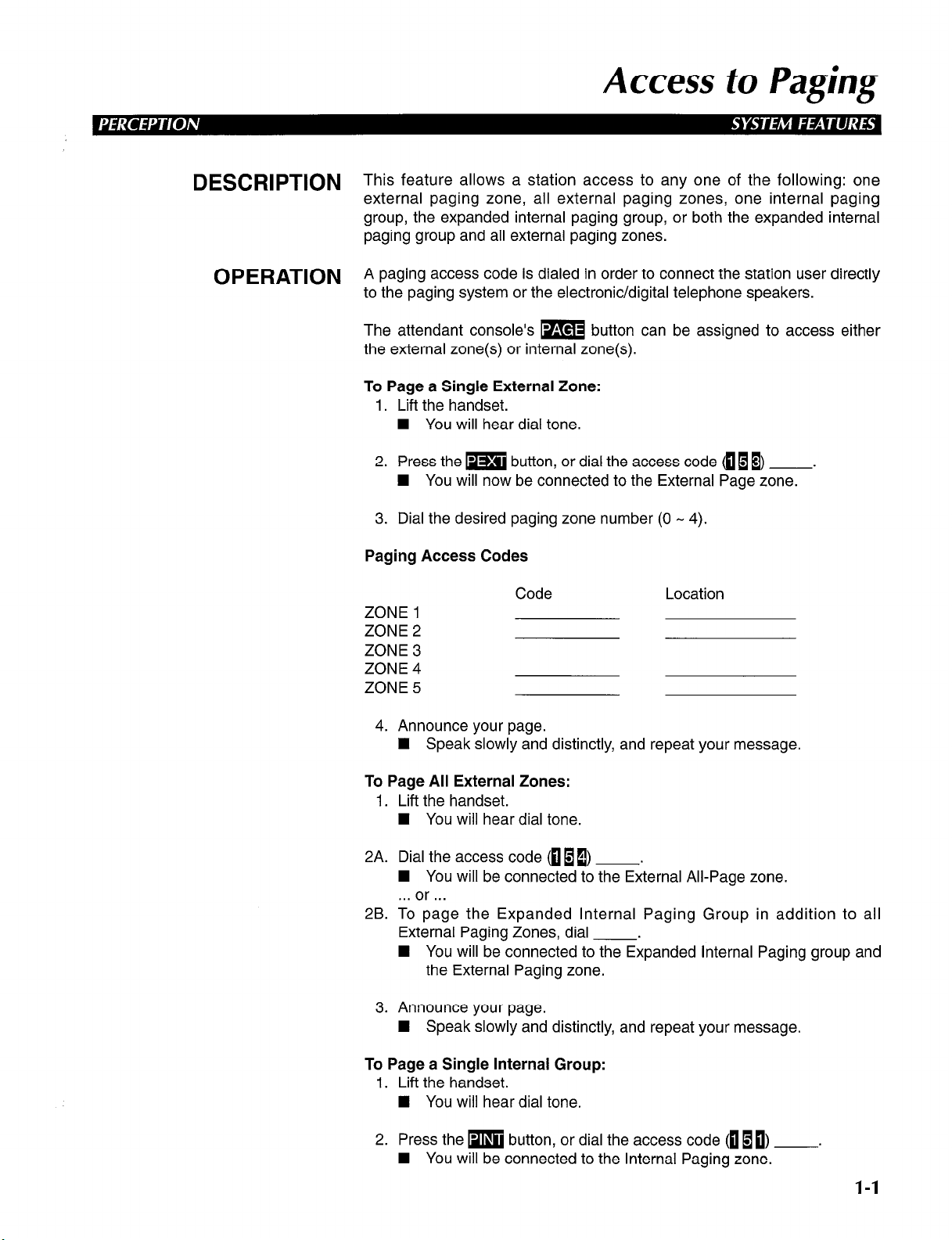
DESCRlPTlON This feature allows a station access to any one of the following: one
external paging zone, all external paging zones, one internal paging
group, the expanded internal paging group, or both the expanded internal
paging group and all external paging zones.
OPERATION A paging access code is dialed in order to connect the station user directly
to the paging system or the electronic/digital telephone speakers.
The attendant console’s m button can be assigned to access either
the external zone(s) or internal zone(s).
To Page a Single External Zone:
1. Lift the handset.
n You will hear dial tone.
2. Press the m button, or dial the access code fli B) .
W You will now be connected to the External Page zone.
3. Dial the desired paging zone number (0 - 4).
Paging Access Codes
Code
ZONE 1
ZONE 2
ZONE 3
ZONE 4
ZONE 5
4. Announce your page.
H Speak slowly and distinctly, and repeat your message.
To Page All External Zones:
1. Lift the handset.
H You will hear dial tone.
2A. Dial the access code <oII) .
n You will be connected to the External All-Page zone.
. . . or . . .
2B. To page the Expanded Internal Paging Group in addition to all
External Paging Zones, dial .
n You will be connected to the Expanded Internal Paging group and
the External Paging zone.
3. Announce your page.
H Speak slowly and distinctly, and repeat your message.
Location
To Page a Single Internal Group:
I. Lift the handset.
n You will hear dial tone.
2. Press the m button, or dial the access code (EI 10) .
H You will be connected to the Internal Paging zone.
l-1
Page 10
Access to Paging
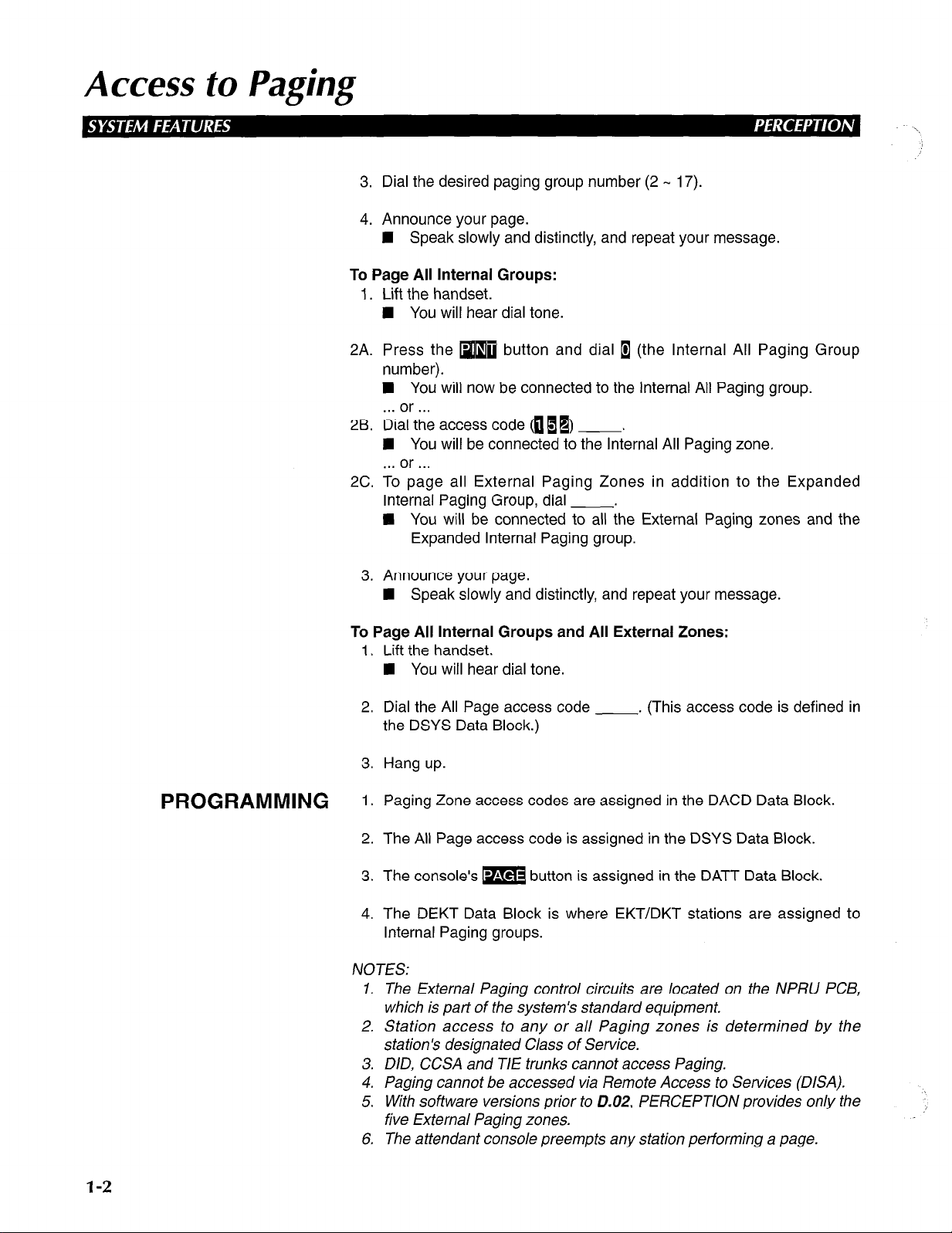
To Page All Internal Groups:
2A. Press the m button and dial 1 (the Internal All Paging Group
26. Dial the access code (0 1 PI .
2C. To page all External Paging Zones in addition to the Expanded
3. Dial the desired paging group number (2 - 17).
4. Announce your page.
n Speak slowly and distinctly, and repeat your message.
1. Lift the handset.
n You will hear dial tone.
number).
n You will now be connected to the Internal All Paging group.
. . . or . . .
n You will be connected to the Internal All Paging zone.
. . . or . . .
Internal Paging Group, dial .
q You will be connected to all the External Paging zones and the
Expanded Internal Paging group.
PROGRAMMING
3. Announce your page.
n Speak slowly and distinctly, and repeat your message.
To Page All Internal Groups and All External Zones:
1. Lift the handset.
n You will hear dial tone.
2. Dial the All Page access code . (This access code is defined in
the DSYS Data Block.)
3. Hang up.
1. Paging Zone access codes are assigned in the DACD Data Block.
2. The All Page access code is assigned in the DSYS Data Block.
3. The console’s m button is assigned in the DATT Data Block.
4. The DEKT Data Block is where EKT/DKT stations are assigned to
Internal Paging groups.
NOTES:
1. The External Paging control circuits are located on the NPRU PCB,
which is part of the system’s standard equipment.
2. Station access to any or all Paging zones is determined by the
station’s designated Class of Service.
3. DID, CCSA and TIE trunks cannot access Paging.
4. Paging cannot be accessed via Remote Access to Services (DISA).
5. With software versions prior to 0.02, PERCEPTION provides only the
five External Paging zones.
6. The attendant console preempts any station performing a page.
l-2
Page 11
Access to Paging
RELATED FEATURES
BENEFITS A
1. Class of Service Restrictions (System).
2. Meet-Me Page (Station).
ccess to paging is convenient to the user since it permits the utilization of
a system-incorporated paging unit and eliminates the need for external
microphones. Additionally, the feature’s characteristic access-flexibility
allows a station to access any or all Paging zones and groups, and thus
eliminates the need for dedicated Paging positions.
External Zone Paging enables the customer to make announcements over
external loudspeakers that can be heard over a wide area. This feature is
especially applicable to large, open, or noisy environments such as
automobile dealerships, warehouses, or workshops. It can also be used in
conjunction with Internal Group Paging, to provide the end-user with a
Paging scheme customized to his or her unique requirements.
In Internal Group Paging, pages over the speakers in electronic/digital
telephones are more private than zone pages. They can be made to
specific groups of station users rather than physical locations. This feature
is especially applicable to office environments, professional business such
as law or accounting offices, and other applications in which low noise
levels must be maintained. It can be used in conjunction with External
Zone Paging, to provide the end-user with a Paging scheme customized
to his or her unique requirements.
1-3
Page 12
Account Codes: Forced, Verifiable, Voluntary
DESCRIPTION
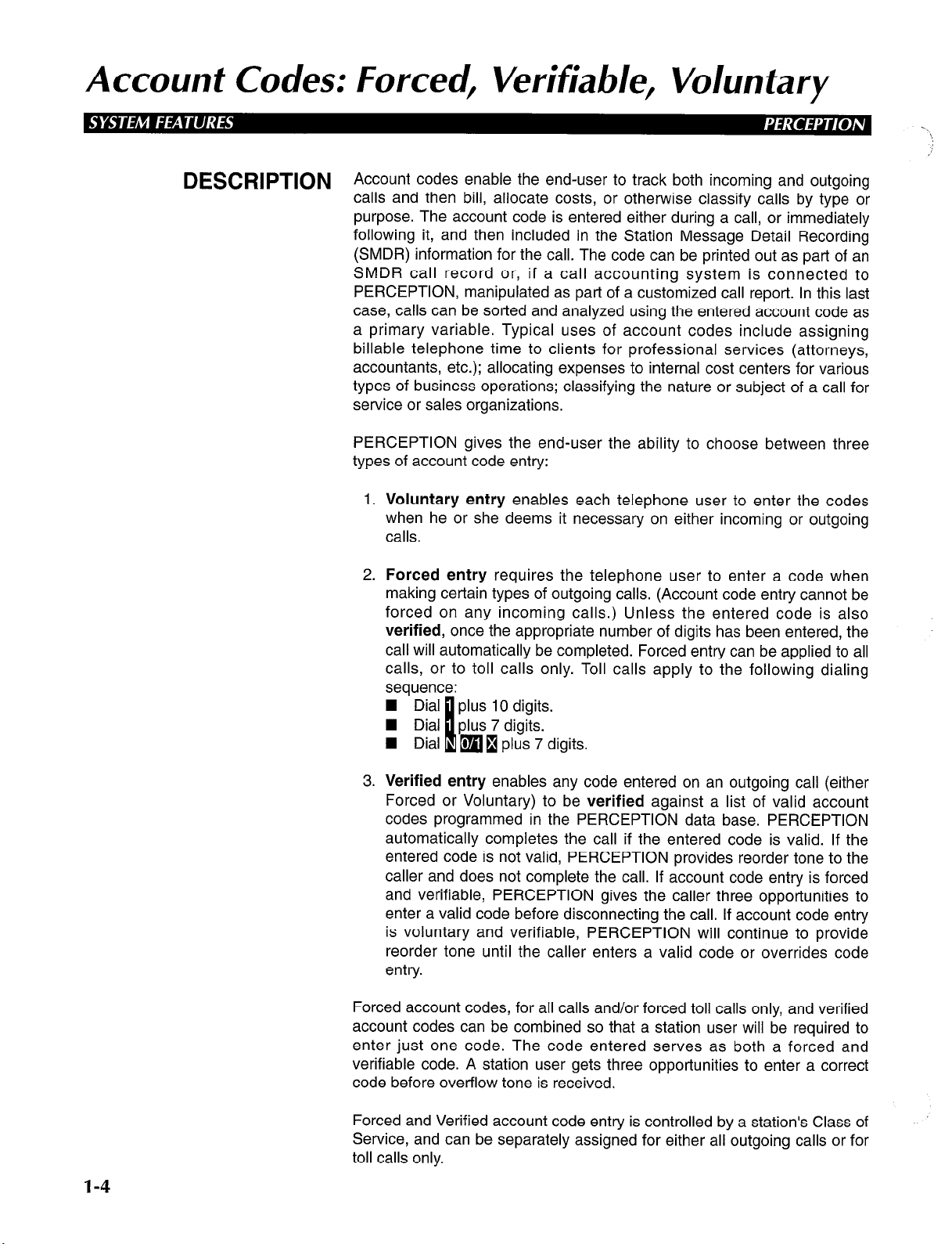
Account codes enable the end-user to track both incoming and outgoing
calls and then bill, allocate costs, or otherwise classify calls by type or
purpose. The account code is entered either during a call, or immediately
following it, and then included in the Station Message Detail Recording
(SMDR) information for the call. The code can be printed out as part of an
SMDR call record or, if a call accounting system is connected to
PERCEPTION, manipulated as part of a customized call report. In this last
case, calls can be sorted and analyzed using the entered account code as
a primary variable. Typical uses of account codes include assigning
billable telephone time to clients for professional services (attorneys,
accountants, etc.); allocating expenses to internal cost centers for various
types of business operations; classifying the nature or subject of a call for
service or sales organizations.
PERCEPTION gives the end-user the ability to choose between three
types of account code entry:
1.
Voluntary entry
when he or she deems it necessary on either incoming or outgoing
calls.
2. Forced entry
making certain types of outgoing calls. (Account code entry cannot be
forced on any incoming calls.) Unless the entered code is also
verified,
call will automatically be completed. Forced entry can be applied to all
calls, or to toll calls only. Toll calls apply to the following dialing
sequence:
once the appropriate number of digits has been entered, the
enables each telephone user to enter the codes
requires the telephone user to enter a code when
1-4
3. Verified entry
Forced or Voluntary) to be
codes programmed in the PERCEPTION data base. PERCEPTION
automatically completes the call if the entered code is valid. If the
entered code is not valid, PERCEPTION provides reorder tone to the
caller and does not complete the call. If account code entry is forced
and verifiable, PERCEPTION gives the caller three opportunities to
enter a valid code before disconnecting the call. If account code entry
is voluntary and verifiable, PERCEPTION will continue to provide
reorder tone until the caller enters a valid code or overrides code
entry.
Forced account codes, for all calls and/or forced toll calls only, and verified
account codes can be combined so that a station user will be required to
enter just one code. The code entered serves as both a forced and
verifiable code. A station user gets three opportunities to enter a correct
code before overflow tone is received.
Forced and Verified account code entry is controlled by a station’s Class of
Service, and can be separately assigned for either all outgoing calls or for
toll calls only.
enables any code entered on an outgoing call (either
verified
against a list of valid account
Page 13
Account Codes: Forced, Verifiable, Voluntary
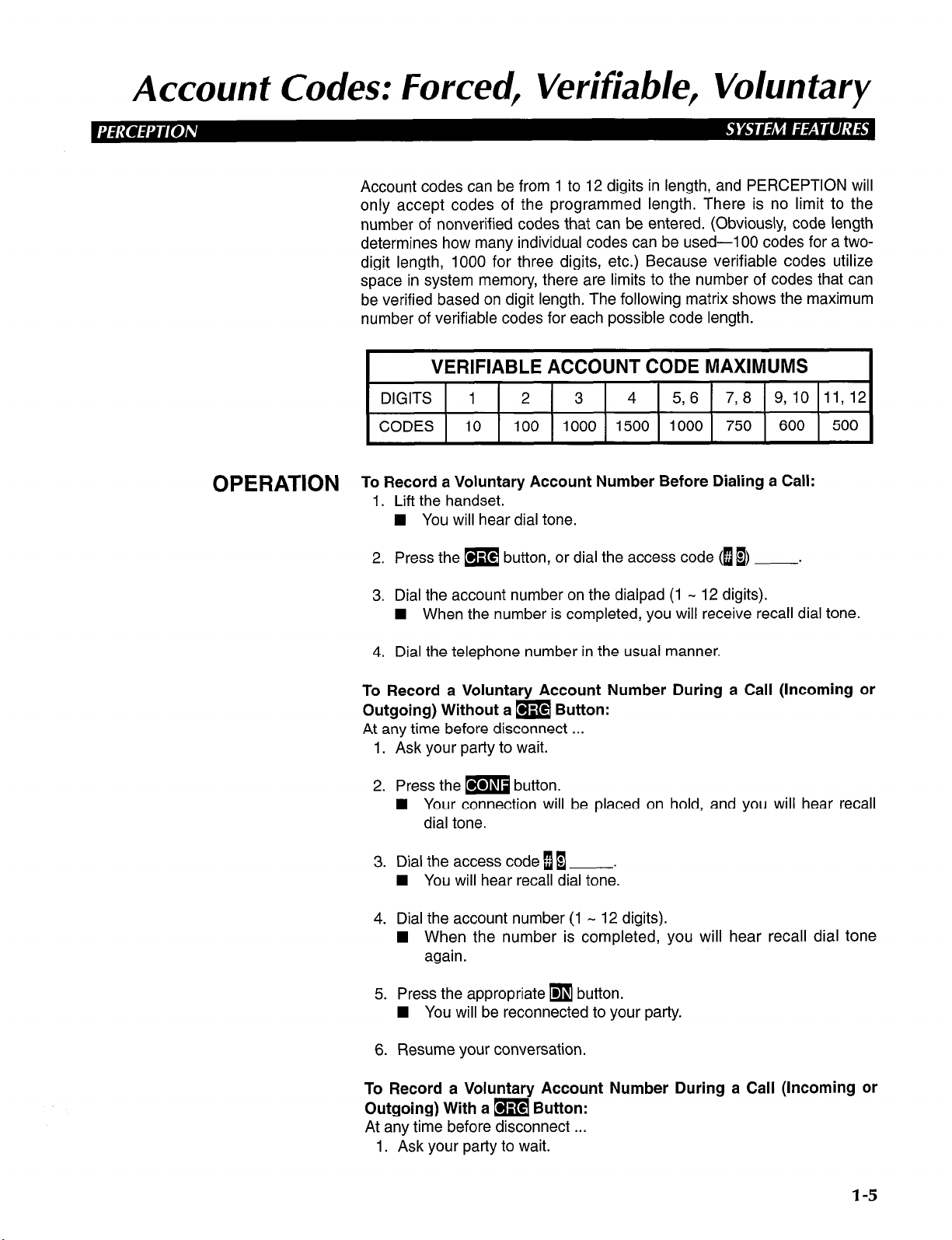
Account codes can be from 1 to 12 digits in length, and PERCEPTION will
only accept codes of the programmed length. There is no limit to the
number of nonverified codes that can be entered. (Obviously, code length
determines how many individual codes can be used-l 00 codes for a twodigit length, 1000 for three digits, etc.) Because verifiable codes utilize
space in system memory, there are limits to the number of codes that can
be verified based on digit length. The following matrix shows the maximum
number of verifiable codes for each possible code length.
VERIFIABLE ACCOUNT CODE MAXIMUMS
DIGITS 1 2 3 4 5, 6 7,8 9,10 11,12
CODES 10 100 1000 1500 1000 750 600 500
OPERATION T; R;;;;ea,;mwy Account Number Before Dialing a Call:
n You will hear dial tone.
2. Press the m button, or dial the access code (l B)
3. Dial the account number on the dialpad (1 - 12 digits).
n When the number is completed, you will receive recall dial tone.
4. Dial the telephone number in the usual manner.
To Record a Voluntary Account Number During a Call (Incoming or
Outgoing) Without a m Button:
At any time before disconnect . . .
1. Ask your party to wait.
2. Press the m button.
H Your connection will be placed on hold, and you will hear recall
dial tone.
3. Dial the access code [I .
n You will hear recall dial tone.
4. Dial the account number (1 - 12 digits).
n When the number is completed, you will hear recall dial tone
again.
5. Press the appropriate
n You will be reconnected to your party.
q
button.
.
6. Resume your conversation.
To Record a Voluntary Account Number During a Call (Incoming or
Outgoing) With a m Button:
At any time before disconnect . . .
1. Ask your party to wait.
l-5
Page 14
Account Codes: Forced, Verifiable, Voluntary
2. Press them button.
n The connection will be placed on hold, the DN LED indicates the
On-hold status, and the CRG LED will light.
3. Dial the account number (1 - 12 digits).
H When the number is completed, the call will automatically be
reconnected.
4. Resume your conversation
To Record a Forced, or a Forced and Verifiable Account Code (Direct
Trunk Access or Least Cost Routing):
1. Access a CO line (by dialing the DTA or LCR access code).
n You will hear dial tone.
2. Dial the distant directory number.
H You will hear recall dial tone.
3. Using the dialpad, dial the l- the DMDR Program).
n The account code is saved
H The system stores dialed directory number to auto-dial queue,
and the trunk call is made.
NOTE: These Forced and Forced/Verifiable Account Codes can be
applicable to either all calls or toll calls only (programming option).
To Record a Verifiable Account Code Before Dialing a Call:
1.
Lift the handset.
H You will hear dial tone.
2.
Press them button.
3.
Dial the I- - 12-digit account code on the dialpad.
n You will hear recall dial tone.
4.
Dial the Direct Trunk access code and the desired telephone number.
4 The trunk call is made.
To Record a Verifiable Account Code During a Call (Incoming or
Outgoing) With am Button:
At any time during conversation . . .
1. Ask your party to wait.
12-digit account code (determined in
to output
to SMDR.
l-6
2. Press the m button.
n You wil hear recall dial tone.
4 The connection will be placed on hold, the DN LED indicates the
On-hold status, and the CRG LED will light.
3. Dial the l- - 12-digit account code.
n The system will store the account code to output to SMDR, and
the call will automatically be reconnected.
4. Resume the conversation.
’
Page 15
Account Codes: Forced, Verifiable, Voluntary
To Record a Verifiable Account Code During a Call (Incoming or
Outgoing) Without am Button:
At any time before disconnect . . .
1. Ask your party to wait, then press the m button.
n You will hear recall dial tone.
2. Dial the CRG access code.
W Your connection will be placed on hold, and you will hear recall
dial tone.
3. Dial the 1- - 12-digit account code.
n The system will store the account code to output to SMDR.
4. Resume your conversation.
To Record a Verifiable Account Code After a Call Is Completed:
This procedure applies when a station user forgets to input an account code
either before, or during a call. The account code can still be entered after the
call is completed, provided it is done prior to disconnecting the trunk.
After the call is completed
system automatically sets the ACT timer. Before the ACT timer expires . . .
1. Press the m button or dial the CRG access code.
H You will hear recall dial tone.
2. Dial the l- - 12-digit account code.
E The system sets the account code, the SMDR is printed out, and
the line locks out.
3. Hang up.
PROGRAMMING This feature is available only with D.04 and later versions of software.
1. Forced and/or verifiable account
Classes of Service in the Class of Service (DCOS) Data Block. (No
programming is required to permit stations to enter account codes on
a voluntary basis.) A specific Class of Service is assigned to each
station in either the Electronic/Digital Telephone (DEKT) or the
Standard Telephone (DSTT) Data Block.
2. Account codes that PERCEPTION will verify are entered in the
Verifiable Account Code (DVAC) Data Block. Verifiable account codes
can be entered from the maintenance terminal (on-site or remotely),
an attendant console, or an attendant-position electronic/digital
telephone.
and
prior to the station user hanging up, the
codes
are assigned to individual
3. Account code length (number of digits) is assigned in the Station
Message Detail Recording (SMDR) Data Block. All valid account
codes must be of this programmed number of digits in length. It does
not matter what type of account codes are being used, a value MUST
be entered in this data block for the feature to be enabled.
I-7
Page 16
Account Codes: Forced, Verifiable, Voluntary
RELATED FEATURES
BENEFITS A
1. Station Message Detail Recording (System).
2. Class of Service (System).
3. Toll Restriction/Class of Service Override Code (System).
ccount codes give the end-user additional control over the operation of
the telephone system. They enable additional revenue to be generated by
accurately tracking billable telephone time on client calls. They also permit
internal costs to be allocated among in-house cost centers for telephone
expenses. And, they are flexible enough to allow the end-user to
manipulate them in ways that serve the unique requirements of his or her
application requirements.
1-8
Page 17
Alphanumeric Trunk ID
DESCRIPTION
OPERATION
PROGRAMMING
This feature enables the end-user to assign an alphanumeric name of up
to 16 characters to each Central Office trunk connected to PERCEPTION.
This name is displayed on the lower row of an electronic or digital
telephone display while an incoming Central Office trunk call is ringing,
and for ten seconds after it has been answered. If the call is forwarded,
hunts, or is transferred, the name display follows the call to its final
destination.
The name can be used to identify a company or person in an executive-
suite application, or a product or sales promotion in an Automatic Call
Distribution (ACD) or inbound call-center operation, or any other
information important to the end-user. It provides the station user with
important information about the call before it is actually answered.
This feature operates automatically once it is programmed.
This feature is available only with D.04 and later versions of software.
Each Central Office trunk (Incoming, Outgoing, Bothway, WATS, and
Foreign Exchange) can be programmed with an alphanumeric ID of up to
16 characters in the Trunk (DTRK) Data Block.
NOTE: An alphanumeric Trunk ID CANNOT be programmed for a DID or
TIE trunk, or any trunk assigned as a private line. Alphanumeric Trunk ID
can be assigned to Central Office trunks routed into PERCEPTION via Tl
trunks.
RELATED FEATURES
BENEFITS
Automatic Call Distribution (Automatic Call Distribution Features).
Alphanumeric Trunk ID provides station users with important information
about an incoming trunk call before it is answered, enabling them to
process the call more efficiently and more effectively. It is an especially
important feature in Executive Suite and Automatic Call Distribution
applications.
1-9
Page 18
Cal/ Forward Busy (System/DID)
DESCRlPTiON Call Forward Busy (System/DID) is used to automatically route incoming
DID or CCSA calls, which encounter a busy tone at a station’s DID or
CCSA directory number, to the attendant operator ONLY.
OPERATION
PROGRAMMING TTn:eh~~~~D~D~~~~~~System/DID) feature access code is programmed
To Use Call Forward Busy (System/DID):
1 A. Press the m button.
n The CFSB LED will flash.
2A. Dial 1 (the only number to which calls can be forwarded).
3A. Press the m button.
n The CFSB LED will light steadily.
. . . or . . .
1 B. Lift the handset.
n You will hear dial tone.
2B. Dial the access code (IuB) .
1 You will hear recall dial tone.
3B. Dial 1.
4B. Dial 1.
n You will hear dial tone.
5B. Hang up.
NOTES:
1. If Call Forward Busy (System/DID) is restricted by a station’s Class of
Service, then either the station will receive overflow tone (if the
station utilizes a Call Forward Busy (System/DID) feature access
code), or the station’s CFSB LED will not light (if the station utilizes a
m button).
2. If an attendant dials the Call Forward cancel code, all Call Forward
information which is currently registered within the system, will be
canceled.
3. Calls may originate from stations which have forwarded their
incoming calls to the attendant.
4. If Call Forward Busy (System/DID) is registered, incoming calls to the
DID/CCSA DN will forward according to the registered forwarding
information. Incoming calls to other DNs, which appear on a
telephone, will ring normally
5. Only one type of Call Forwarding may be activated at one time. The
last-registered Call Forward entry overrides all previously-assigned
entries.
6. If any type of Call Forwarding and Station Hunting are set on a
station simultaneously, Call Forwarding takes precedence.
7. CFSB-type forwarding can only be set to forward to the attendant
operator (0).
I-10
Page 19
Cal/ Forward Busy (System/DID)
If CFSB is set on a station, and then another type of call forward (i.e.,
8.
CFD) is set at that station, CFSB is temporarily deactivated. Once the
other call forward is canceled, CFSB becomes reactivated again.
RELATED FEATURES 1.
2.
3.
4.
5.
6.
7.
8.
9.
BENEFITS This feature allows a station user to forward incoming DID calls to the
attendant while forwarding other types of calls to a different location, when
his or her extension is busy. This flexibility increases the end-user’s
telephone productivity.
Class of Service Restrictions (System).
Call Forward All Calls (Station).
Call Forward Busy/No Answer (Station).
Call Forward Busy (Station).
Call Forward No Answer (Station).
Call Forward to Trunk (Station).
Station Hunting (Station).
Saved Call Forward and Message Waiting (System).
Call Forward Busy/No Answer (System/DID) (System).
1-11
Page 20
Cal/ Forward Busy/No Answer (System/DID)
DESCRIPTION
OPERATION
Call Forward Busy/No Answer (System/DID) is used to automatically route
incoming DID or CCSA calls at a station’s DID or CCSA directory number,
which encounter either a busy tone or are not answered within a
predetermined amount of time, to the attendant operator ONLY.
To Use Call Forward Busy/No Answer (System/DID):
IA. Press them button.
W The CFSN LED will flash.
2A. Dial 1 (the only number to which calls can be forwarded).
3A. Press the m button.
n The CFSN LED will light steadily.
. . . or . . .
1 B. Lift the handset.
n You will hear dial tone.
2B. Dial the access code ([[m) .
n You will hear recall dial tone.
3B. Dial B.
48. Dial 1.
n You will hear dial tone.
PROGRAMMING
5B. Hang up.
The Call Forward Busy/No Answer feature access code is programmed in
the DACD Data Block.
NOTES:
1. If Call Forward Busy/No Answer (System/DID) is restricted by a
station’s Class of Service, then either the station will receive overflow
tone (if the station utilizes a Call Forward Busy/No Answer
(System/DID) feature access code), or the stations CFSN LED will
not light (if the station utilizes a m button).
2. If an attendant dials the Call Forward cancellation code, all Call
Forward information which is currently registered within the system,
will be canceled.
3. Calls may originate from stations which have forwarded their
incoming calls to the attendant.
4. If Call Forward Busy/No Answer (System/DID) is registered, incoming
calls to the station’s DIDKCSA DN will forward according to the
registered forwarding information. Incoming calls to other DNs, which
appear on a telephone, will ring normally.
5. Only one type of Call Forward may be activated at one time. The lastregistered Call Forward entry overrides all previously-assigned
en tries.
6. If any type of Call Forward and Station Hunting are set on a station
simultaneously Call Forward takes precedence.
7. CFSN-type forwarding can only be set to forward to the attendant
operator (0).
1-12
Page 21
Cal/ Forward Busy/No Answer (System/DID)
8.
If CFSN is set on a station, and then another type of call forward (i.e.,
CFD) is set at that station, CFSN is temporarily deactivated. Once the
other call forward is canceled, CFSN becomes reactivated again.
RELATED FEATURES ;.
3:
4.
5.
6.
7.
8.
9.
BENEFITS This feature allows a station user to forward incoming DID calls to the
attendant while forwarding other types of calls to a different location, when
his or her extension is either busy or there is no answer. This flexibility
increases the end-user’s telephone productivity.
Class of Service Restrictions (System).
Call Forward All Calls (Station).
Call Forward Busy/No Answer (Station).
Call Forward Busy (Station).
Call Forward No Answer (Station).
Call Forward to Trunk (Station).
Station Hunting (Station).
Saved Call Forward and Message Waiting (System).
Call Forward Busy (System/DID) (System).
1-13
Page 22
Camp-on
DESCRIPTION
OPERATION
This feature enables callers to reserve access to a busy station or trunk.
One short warning tone from a station’s speaker advises the user that
either the attendant or another station has camped on an outside call to
that station. When this occurs, the user has two choices:
1. Ignore the call; it will return to either the station or the attendant,
whoever sent the call.
2. Terminate the existing call and accept the new one.
NOTES:
1. When Camp-on is used on a standard telephone, the short warning
tone will be heard through the handset. The party on the original
connection does not hear this warning tone.
2. Call Waiting and Camp-on are mutually exclusive features. All
stations come equipped with Call Waiting (CWT). If CWT is denied in
the station’s Class of Service, then the station has Camp-on. Campon cannot be denied in a station’s Class of Service.
To Accept the Camp-on Call:
1. Complete the original call and hang up.
n The telephone will ring.
n The DN led will flash.
2. Answer the new call.
PROGRAMMING
RELATED FEATURES
BENEFITS
Camp-on is assigned to a station only when Call Waiting has been denied
to that station in its Class of Service Data Block (DCOS).
The warning tone for this feature is assigned in the DEKT and/or DSTT
Data Blocks.
Call Waiting (Station).
Camp-on enhances station-user efficiency by eliminating the need for
constantly redialing a busy station. Station users waste less time because
the system performs the operations for them.
.I
l-14
Page 23
Class of Service Restrictions
DESCRlPTlON PERCEPTION provides a maximum of 16 (0 - 15) Classes of Service
(COS). A specific class is assigned to each station and particular trunks in
order to determine its customized access to features and outgoing trunks.
OPERATION
1. A station or trunk can be allowed or denied access to a particular
feature through the assignment of a particular COS.
2. Each COS is defined by the allowance or denial of the following
features:
n
Account Codes (Forced and Verifiable)
n
ACD/MIS Call Pick-up
n
All types of paging
n
Attendant Control Override
n
Automatic Callback
n
Call Forward-(All Calls, Busy, No Answer, Busy/No Answer,
Busy/No Answer DID, and Busy-DID)
n
Call Pickup-(Directed, Group)
Call Waiting
n
n
Data Group 0 - 15 (Data Security)
n
Direct Trunk Access
n
Least Cost Routing Class 1 - 3
n
Lodging/Health Care
n
Off-hook Call Announce
n
Override
n
Paging Zones
n
Remote Log In
q
Speed Dial-System
n
Supervisor Monitor Tone and LCD Display
n
Trunk Group 0 - 15
PROGRAMMING The Class of Service (DCOS) Data Block defines the 16 Classes of
RELATED FEATURES
Service. A COS is then assigned to each station by entering the relevant
class number (0 - 15) in response to the COS prompt in the DSTT, DEKT
and DTGP (TIE, CCSA, and DID trunk groups only) Data Blocks.
1. Access To Paging (System).
2. Intercept (System).
3. Toll Restriction (System).
4. Call Forward-All Calls (Station).
5. Call Pickup-Directed (Station).
6. Call Pickup-Group (Station).
7. Call Waiting (Station).
8. Conference (Station).
9. Direct Outward Dialing (Station).
10. Trunk Group Access Control (Attendant).
11. Data Security Groups (Data).
12. Forced Account Codes (Station).
NOTES:
1. All features are allowed to a COS by default (with the exception of
HRM and OCA). The customization of each COS must be achieved
through the denial of specific features.
l-15
Page 24
C/ass of Service Resfricfions
2. In Lodging/Health Care systems, the code HRM must be entered in
the COS of guest-room stations. This activates the Lodging/Health
Care features for those stations. While ordinarily, the entrance of a
feature access code in the DCOS Data Block indicates a feature
denial, in this case, the code entrance signifies an allowance.
BENEFITS C’
by which stations, enabling the station user to control how the system is
used. It can be used with Toll Restriction to further customized individual
stations’ outgoing call capabilities.
ass of Service assignment determines which features may be accessed
1-16
Page 25
Common Control Switching Arrangement Access
DESCRIPTION
OPERATION
PROGRAMMING
PERCEPTION can access a Common Control Switching Arrangement
(CCSA) network for both network inward dialing to the system, and direct
outward dialing to the CCSA network. Additionally, many features similar
to those provided on the public exchange network, are provided within the
CCSA network.
1. The interface for a CCSA line is usually an E & M TIE trunk circuit
(NEMU PCB).
2. Incoming and outgoing call operation is the same as that for a TIE
trunk.
All CCSA trunk parameters are specified within the DTGP and DTRK Data
Blocks.
NOTE: Number Translation and/or digit absorption can be provided on
incoming dialed numbers from TIE/CCSA and DID trunks. This process is
controlled by the OAB, IAB, TRNI, and TRN2 prompts in the DTGP Data
Block as follows:
OAB (Outgoing Absorb Digits)-Identifies the specific digits which are to
be ignored for purposes of Toll Restriction. While these digits will still be
outpulsed, the system will not acknowledge them as the first digits of a
destination number.
TO PROGRAM: Enter either the specific digits which are to be
absorbed or NONE. A maximum of two digits can be absorbed by the
system.
IA9 (Incoming Absorb Digits)-Defines the number of digits that are to be
stripped off an incoming dialed number from a TIE/CCSA or DID trunk.
TO PROGRAM: Enter either the number of digits to be absorbed
(maximum of two digits), or NONE.
TRNl (Translated Number 1)-Defines the absorbed digit (IAB) which is
to be translated into another digit(s). (See examples.)
TO PROGRAM: Enter either X # Y or X # YY.
X = The digit which is to be translated into another digit or digits.
In a case where two digits are absorbed, only the second digit
will be translated.
Y or YY = The translated digit or digits which are to take the
place of the initially-absorbed digit (X).
TRN2 (Translated Number 2)-Defines the absorbed digit (IAB) which is
to be translated into another digit(s). This parameter is the same as the
TRNI entry
TO PROGRAM: Enter either X # Y or X # YY:
EXAMPLE A:
IAB= 1
TRNI = 9#2
TRN2 = 8#3
Three Digits Received from CO: 900 - 999; 800 - 819
To Ring Three-digit DNs: 200 - 299; 300 - 319
1-17
Page 26

Common Control Switching Arrangement Access
EXAMPLE B:
IAB=2
TRNl = 9#2
TRN2 = 8#3
Four Digits Received from CO: 5900 - 5999; 5800 - 58 19
To Ring Three-digit DNs: 200 - 299; 300 - 319
EXAMPLE C:
IAB=2
TRNI = 9#21
TRN2 = 8#32
Four Digits Received from CO: 5900 - 5990; 5800 - 5890
To Ring Four-digit DNs: 2 100 - 2199; 3200 - 3299
RELATED FEATURES ;.
3:
4.
5.
6.
BENEFITS A
ccess to Common Control Switching Arrangement enables a
PERCEPTION user to reduce telecom costs by incorporating the system
into a CCSA-type private network.
Direct Inward Dialing (System).
Multiple Trunk Groups (System).
TIE Trunks (System).
Call Forward-Busy (Station).
Call Forward-No Answer (Station).
Direct Outward Dialing (Station).
1-18
Page 27
Consoleless Operation
DESCRIPTION
OPERATION
PROGRAMMING
RELATED FEATURES
BENEFITS
PERCEPTION can be operated without an attendant console. In this
situation, incoming trunk calls can be routed to individual stations,
attendant-position electronic/digital telephones, or the UNA device.
PERCEPTION will operate in the Night Service mode in a consoleless
operation, unless there is at least one Attendant-Position EKT/DKT
(AEKT/ADKT) with a m button to place the system in the Day mode.
Whenever the system is powered up and a console is not used,
PERCEPTION will automatically assume a consoleless mode, which is
identical to Night mode (see Night Service). In this mode of operation,
each trunk rings at the station assigned as the night number (NIT prompt)
in the DTRK Data Block, unless the system is equipped with an AttendantPosition EKT/DKT with a m button, which is programmed in the DEKT
and DSD2 Data Blocks.
See Night Service.
1. Attendant-Position Electronic/Digital Telephones (DSS/DDSS).
2. Direct-in Lines (System).
3. Night Service (System).
Consoleless operation can reduce costs, both by allowing an attendant to
perform other duties during slow periods and by eliminating the need to
employ an attendant on a daily basis.
In tenant systems, executive suites, and distributed call processing
applications, there is a need for several answering positions, each
controlling specific trunks, but not requiring all the power of an attendant
console. A PERCEPTION, in consoleless operation utilizing 20-button
LCD electronic/digital telephone (with or without DSSDDSS consoles) or
other types of telephones as answering positions, satisfies this
requirement perfectly.
This feature gives end-user a great deal of flexibility to configure the call
answering/processing that best fits his or her unique application
requirements.
1-19
Page 28
Dafa Transmission- Voice Band
,:
\.
DESCRIPTION
OPERATION
PROGRAMMING
RELATED FEATURES
BENEFITS
PERCEPTION is suitable for voice-band data transmission (via modem),
and is compatible with conventional modems operating at transmission
rates of up to 9600 bps.
A standard telephone interface circuit from an NSTU PCB is compatible
with conventional modems.
Any station which is to activate data transmission should be programmed
not to receive warning tone. This will prevent the transmission interruption
and data scrambling which could occur if warning tone were to sound
during a data transferring session. Warning tone is denied by entering N in
the WTA entry of the DEKT and DSTT Data Blocks. Denying warning tone
also denies features which normally generate warning tone (Station
Verification, Call Waiting, etc.) and the non-use of Camp-on indicator
tones (Camp-on is still operable).
Data Switching (all Features).
The ability of PERCEPTION to interface modems to standard station ports
gives the station user an inexpensive method for low-speed transmission
of data, both through the system and over the telephone network.
l-20
Page 29
Dialed Number /den tifka tion Service (DNIS)
DESCRlPTlON The Dialed Number Identification Service (DNIS) feature enables a
PERCEPTION user to take advantage of the DNIS capability offered by all
major long distance services. DNIS will interface with PERCEPTION at an
E&M TIE line on either an NEMU or NDTU PCB, or at a DID port on either
an NLSU or NDTU PCB. The system will be programmed by trunk group
(in the DTGP Data Block) to treat received digits on each E&M TIE line
and DID port as either a TIE/DID trunk call, or a DNIS call. If TIE or DID
trunk operation is programmed, no changes from current operation are
required. If DNIS is programmed, the system will route the incoming calls
(based on the digits received; one to five digits permitted) to an internal
directory number, an ACD group pilot number, a distributed hunting group,
a voice mail port, the attendant console (UNA in Night service), or UNA in
either Day or Night service. DNIS calls can only be routed to a single
destination. Call preceded by invalid DNIS digits will be routed to Intercept
2.
The end-user will also be able to program an alphanumeric identifier, of up
to 16 characters, that will be displayed on LCD telephones when the DNIS
call is routed to it. If a DNIS call hunts, or is transferred or forwarded, the
DNIS display will follow the call and be displayed on the final destination. If
the DNIS call is routed to a pooled DIL destination, the display will be
presented on each telephone on which the call rings.
PERCEPTION will send a message to the MIS processor for each DNIS
call routed into an ACD group, so that this information can be included in
the relevant agent and group reports. The alphanumeric designation for
each DNIS number will be part of the download from PERCEPTION to the
MIS processor. For non-ACD calls, the DNIS number will be included in
the SMDR information (in characters 35 - 39 on the printout field).
OPERATION A
n incoming DNIS call is basically routed in the following manner:
1. PERCEPTION compares the received number to the table in the
DNIS Data Block.
H If the number is not entered in the data block, the call is routed to
Intercept 2.
2. If the programmed destination is the pilot number of an ACD group,
the call enters the group queue and is processed as a normal ACD
call.
n The programmed display is shown at the answering agent’s
telephone.
4 The DNIS number is included in the information sent to the MIS
processor for the call and the agent.
3. If the programmed destination is the master number of a distributed
hunt group, the call will be routed to the station in the group that
should receive the next call in the normal manner.
H The display will be presented to that telephone.
4. If the programmed destination is a station that is call forwarded, or if
the answering station then transfers the call, the call will follow the
programmed forward or transfer to either an internal or external DN.
Page 30
Dialed Number Identification Service (DNIS)
n The programmed display will follow the call to the destination
telephone (if the forward or the transfer is to an internal DN) and
will be presented to that telephone.
5.
If the call is routed to the attendant console, or rings no answer from
a station to the attendant console and is then transferred to another
station, the programmed display will be presented to the final
destination station.
PROGRAMMING 1.
RELATED FEATURES
BENEFITS S
The DNIS numbers, destinations, and alphanumeric displays are
programmed in the DDNI Data Block. The system will also refer to the
DDNI Data Block for routing and other handling instructions for calls
received via a port assigned to a DNIS trunk group.
NOTE: The DNIS message (for example: “ABC COMPANY”) will be
shown on the LCD display only when a DNIS message is registered at
the DIS entry in the DDNI Data Block. If NONE is registered at the DIS
entry, current message (“TXXXX CALLING’? will be shown on the LCD
display.
2. The assignment of a trunk group as a DNIS group is programmed in
the DTGP Data Block.
1. ACD/MIS (ACD/MIS).
2. Call Forward-No Answer (Station).
3. Station Hunting (Station).
4. Call Transfer (Station).
5. Voice Mail Connection (System).
6. Universal Night Answer (System).
7. Night Service (System).
8. Intercept (System).
9. Direct Inward Dialing (System).
ince DNIS numbers are programmed by trunk group, this feature allows
incoming calls to be routed to the proper channels, thus enabling calls to
be immediately and properly handled by the most competent personnel to
handle them. Proper identification of incoming and outgoing calls also
makes the various ACD groups’ report printouts easier to evaluate.
1-22
Page 31

Direcf-in line
DESCRlPTlON This feature permits an incoming trunk to be assigned to a specific station
or hunt group, so that an incoming trunk call will ring directly at the
specified station or hunt group. A Direct-in Line may be assigned to either
the same or an alternate station (or hunt group) during day and night
operation. Direct-in Lines are particularly applicable to Attendant-Position
Electronic/Digital Telephones, either with or without associated Direct
Station Selection Consoles, and Automatic Call Distribution Groups.
OPERATION Day and night trunk-to-station Direct-in Line assignments are flexible, and
can be altered by the system attendant.
To Make Direct-in Line Connections:
1. Dial the directory number.
n The EXCL SRC LED will light steadily when the first digit is
dialed.
n The voice path to the caller will be broken.
4 The DEST directory number will be displayed as the digits are
dialed.
n STATUS will display RNG, and you will hear ringing tone.
2. Press the m button, or dial the access code (1 i It)
W The LPK LED and all displays will go out.
W The RLS LED will light, the console will become idle, and the
caller will hear ringing tone.
NOTES:
1. If you want to announce the call, wait for the called party to answer
before pressing the m button
2. If the call remains unanswered for ( ) seconds, the call will be
returned to your console as a Timed Recall. (The TIM LED will
display in the ICI display area.)
3. Some or all of the system’s CO trunks may be assigned to ring
specific directory numbers (DNs).
4. Once a trunk-to-station assignment is changed by the attendant, it is
stored in random access memory and remains effective until the
system is reloaded.
5. A trunk-to-station assignment may be changed by the attendant any
time when Night Service is not activated.
6. A trunk may not be assigned to multiple DNs; however, one or more
trunks may be assigned to the same DN in Versions D.02 software
and below. In Versions 0.03 software and above, DIL-delayed
ringing is allowed in the Day mode. See this feature for further
explanation.
To change Night Destinations, see Night Service (Attendant Feature).
7.
8. Trunks can be routed directly to the pilot number for an ACD Group
or a Distributed Hunting Group.
.
PROGRAMMING This feature is initially assigned in the DTRK Program at the DAY and NIT
prompts, although the attendant has the ability to alter assigned trunk-tostation connections.
l-23
Page 32

Direct-in Line
RELATED FEATURES
BENEFITS
1. Automatic Call Distribution/Management Information System
(ACD/MIS).
2. Attendant-Position Electronic/Digital Telephone (DSWDDSS).
3. Direct-in Line Pooling (System).
4. Consoleless Operation (System).
5. Delayed Ringing (System).
The Direct-in Line feature allows any trunk to ring directly at any station
without having to go through an attendant. This reduces the cost of
handling incoming calls by reducing the call load of an attendant, or by
enabling the system to operate without an attendant. A Direct-in Line
connection also allows a trunk or group of trunks to ring directly to a group
of stations that represent a particular service group. This feature gives the
end user the flexibility necessary to configure the call
answering/processing arrangement that best fits his or her unique
application requirements.
1-24
Page 33

Direct-in Line Pooling (Delayed Ringing)
DESCRIPTION
OPERATION
PROGRAMMING
When the system is in the Day mode of operation, direct-in line trunks may
utilize the Direct-in Line Pooling feature. This feature allows up to eight
DNs to be assigned to ring either immediately, or after a preset period of
time (delayed ringing) per trunk. Stations set for delayed ringing will
receive a visual indication of an incoming call before ringing begins. If a
pooled DN is busy, then the call will follow the programmed hunt sequence
for that DN, and continues to ring at the other programmed stations. When
the call is answered on one DN, the other DNs become idle, freeing them
to answer another call.
Automatic.
The termination destination for each DIL trunk, whether it is using just the
pooling feature or both pooling and delayed ringing, is programmed in the
DTRK Data Block, at the DAY prompt.
The timing for delayed ringing is established in the DSYS Data Block, at
the DLY prompt.
NOTES:
1. These features are available only in Versions 0.03 software and
above. For operation of Direct-in Lines on earlier versions of
software, refer to the Direct-in Line feature.
2. A maximum of eight DNs per trunk can be assigned to ring.
3. The delay ring timer is a system timer and not set for each trunk.
4. If an attendant console is programmed at the DAY prompt, all other
DN assignments will be ignored.
RELATED FEATURES
BENEFITS
1. Attendant-Position Electronic/Digital Telephone (DSSDDSS).
2. Direct-in Line (System).
3. Consoleless Operation (System).
Direct-in Line Pooling enables up to eight station users to share incoming
call answering duties for a single trunk. Typically, this feature would be
used by members of a single department or work group, although it would
be valuable in virtually any application that requires several people to
share answering duties for a specific incoming trunk. The ability to delay
or prevent ringing at any directory number increases the system’s call
processing flexibility.
1-25
Page 34

Direct Inward Dialing
DESCRIPTION
OPERATION Automatic.
Direct Inward Dialing (DID) allows an incoming call from the network to
reach a specific station without attendant assistance. Because incoming
DID calls route into the system over shared trunk facilities, the end-user
can use this feature to reduce trunking costs. DID service is beneficial in a
situation where there is a high volume of calls which should go directly to
specific stations. Since calls would ordinarily be routed through an
attendant, the use of DID reduces the number of necessary attendants in
large installations. The use of DID trunks requires that the central office
also be equipped for DID service.
NOTES:
1. When the central office accesses a DID trunk in PERCEPTION, the
2. PERCEPTION DID trunks may be set for either DTMF or dial-pulse
3. Two Listed Directory Numbers (LDNs) can be registered per system
4. When the system is in Night Service, calls to LDNs will automatically
5. Number Translation and/or digit absorption can be provided on
directory number of the desired station within the PBX will
automatically be outpulsed. PERCEPTION then translates the
received digits to route the call to the appropriate station.
signaling (DTMF is strongly recommended) and can use either
immediate start, wink start, or delay-dial operation.
so that directed incoming calls will automatically be routed to an
attendant. When each call comes in, the attendant console’s ICI
display panel will display either LNl or LN2. Once the call is
answered, the attendant can extend an incoming call to appropriate
system stations. In tenant service, LDN calls will be routed to
attendant 0 (tenant 0).
be routed to the DN or UNA that is specified by the NT1 and NT2
entries in the DSYS Data Block. LDN night assignments cannot be
altered by an attendant.
incoming dialed numbers from TIE/CCSA and DID trunks. This
process is controlled by the OAB, IAB, TRNl, and TRN2 prompts in
the DTGP Data Block as follows:
1-26
OAB (Outgoing Absorb Digits)-Identifies the digits that are to be
ignored for purposes of Toll Restriction. These digits will be
outpulsed, but will not be acknowledged by the system as the first
digits of a destination number.
TO PROGRAM: Enter either the specific digits which are to be
absorbed or NONE. A maximum of two digits can be absorbed by
the system.
IAB (Incoming Absorb Digits)-Defines the number of digits that are
to be deleted from a dialed number that is transmitted over a DID
trunk.
TO PROGRAM: Enter the number of digits (maximum: 2 digits)
or NONE.
TRNI (Translated Number I)-Defines the absorbed digit (IAB)
which is to be translated into another digit(s). (See examples.)
Page 35

Direct In ward Dialing
TO PROGRAM: Enter either X # Y or X # YY
X = the digit which is to be translated into another digit or
digits (when two digits are absorbed, only the second digit
will be translated).
Y or YY = the digit or digits which are to take the place of the
initially-absorbed digit (X).
TRN2 (Translated Number 2)-Defines the absorbed digit (IAB)
which is to be translated into another digit or digits. This parameter is
the same as TRNl (see examples).
TO PROGRAM: EnterX# Y orX # YY:
X = The digit which is to be translated into another digit or
digits (when two digits are absorbed, only the second digit
will be translated).
Y or YY = The digit or digits which are to take the place of the
initially-absorbed digit (X).
EXAMPLE A:
IAB= 1
TRNl = 9#2
TRN2 = 8#3
Three Digits Received from CO: 900 - 999; 800 - 819
To Ring Three-digit DNs: 200 - 299; 300 - 319
PROGRAMMING
RELATED FEATURES
EXAMPLE B:
IAB=2
TRNl = 9#2
TRN2 = 8#3
Four Digits Received from CO: 5900 - 5999; 5800 - 58 19
To Ring Three-digit DNs: 200 - 299; 300 - 319
EXAMPLE C:
IAB=2
TRNl = 9#21
TRN2 = 8#32
Four Digits Received from CO: 5900 - 5990; 5800 - 5890
To Ring Four-digit DNs: 2100 - 2199; 3200 - 3299
1. All DID trunk parameters are set via the DTGP and DTRK Data
Blocks.
2. LDNs are specified in the LNl and LN2 entries of the DSYS Data
Block. These numbers cannot conflict with other station numbers.
1. CCSA Access (System).
2. TIE Trunks (System).
3. Call Forward-Busy (Station).
4. Call Forward-No Answer (Station).
5. Station Hunting (Station).
NOTE: The Telco will assign a seven-digit (including office code) directory
number to each DID station. However, only the last three or four digits will
be transmitted over the trunks to PERCEPTION. The system program
l-27
Page 36

Direct Inward Dialing
then correlates the transmitted digits with the DID station’s two-, three-, or
four-digit system directory number.
BENEFITS
The use of Direct Inward Dialing allows a caller to reach a specific station
directly, without attendant interception. This both reduces the number of
necessary attendants, and frees an attendant for other duties. It also
allows calls to a specific person or group to be answered with less delay.
This feature is particularly applicable to executive suites, inside sales and
customer service organizations, and individual executives for important
incoming calls.
1-28
Page 37

Disfincfive Ringing
DESCRIPTION
OPERATION
PROGRAMMING
RELATED FEATURES
PERCEPTION provides Distinctive Ringing patterns, which enable a
station user to distinguish between incoming station-to-station calls and
trunk/attendant-to-station calls. An additional tone sequence is supplied to
indicate an automatic callback to a station, and varies according to the
absence or presence of the Handsfree Answerback capability.
Automatic.
NOTES:
The following ringing patterns are provided by PERCEPTION:
1. Station-to-station calls: 1 -second on, 3-seconds off, repeating.
2. Trunk/attendant-to-station calls: 0.4-second on, O.P-second off,
0.4-second on, 3-seconds off, repeating.
3. Automatic Callback tone to a station which has Handsfree
Answerback capability: Tone burst over the station speaker
(0.5-second on).
4. Automatic Callback tone to a standard telephone or electronic/digital
telephone, which does not have Handsfree Answerback capability:
0.5~second on, 0.5-second off, repeating for 6 seconds.
None.
1. Immediate Ringing (System).
2. Automatic Callback (Station).
3. Tone Buzzing (Electronic/Digital Telephone).
4. Tone Ringing (Electronic/Digital Telephone).
BENEFITS
Distinctive Ringing patterns provide an immediate indication of what type
of call is ringing at a station. This allows a station user to answer a ringing
station in the most appropriate manner.
l-29
Page 38

Emergency Ringdown
DESCRIPTION
OPERATION
PROGRAMMING
RELATED FEATURES
BENEFITS
This feature allows a user to indicate the destination for an emergencv
signal (station-to-station ring) when a station goes off-hook, but does not
complete dialing a valid number within a programmed time period (Dial
Pulse Timeout and Line Lockout Time). The destination can be
programmed as either a specific station, the attendant, or the system UNA
device. An LCD electronic/digital telephone, or the attendant, will display
the off-hook telephone’s directory number. A specific
assigned the destination with an emergency or alarm designation.
The assignment destination for Emergency Ringdown is programmed in
either the DEKT or DSTT Data Block.
All (Lodging/Health Care).
Emergency Ringdown is intended to primarily enhance guest security in
Lodging/Healthcare applications. If a guest or patient suffers an accident,
medical problem, or break-in, and attempts to make a call that cannot be
completed, an emergency station is notified, and help can be dispatched
almost immediately. In other applications, such as warehousing or
classrooms, this feature can provide added station user security and
reduce the customer’s liability.
q
button may be
l-30
,
Page 39

Flexible Numbering
DESCRlPTlON
The Flexible Numbering Plan allows for flexible station directory number
assignment, as well as for the customization of trunk and special service
access codes. Such flexibility allows assignments to be made in
accordance with a customer’s unique requirements and preferences.
OPERATION None.
PROGRAMMING Numbering assignments are made during installation programming in
accordance with the numbering plan desired by a particular customer.
Specific assignments are made in the Data Block which corresponds to
each telephone or code type. The various stations and features which
require such number assignment are as follows:
n Electronic/Digital Telephones-DEKT Data Block
W Standard Telephones-DSTT Data Block
n Trunk Access Code-DTGP Data Block
n Feature Access Code-DACD Data Block
n Least Cost Routing-DLCi/DLC2 Data Block
n Lodging/Health Care-DHMF Data Block
n Data Stations-DDIU Data Block
n Listed Directory Numbers-DSYS Data Block
n Remote Access Directory Number-DSYS Data Block
n All Call Page-DSYS Data Block
NOTES:
1. Access code i is always assigned to the attendant console by
system software.
2. Access code 1 is not permitted to be used as an access code for a
station. Access code 1 may, however, be used as the LCR access
code or as a trunk group access code.
3. Rotary dial telephones use single-digit prefixes in place of the 1 and i
buttons. The digits, which are composed of these prefixes, however,
cannot conflict with any access codes registered in the system.
4. Mixed l-, 2-, 3-, or 4-digit numbering is possible, as long as it does
not impose a numbering conflict (e.g., if 51 is assigned as a DN, then
neither 5 nor 51X can be assigned as access codes).
5. Feature access codes are preprogrammed, although they can be
changed in the DACD Data Block in order to accommodate a
customer’s unique requirements or preferences.
6. In Version A levels of software, the system maximum number of
different directory numbers is 200. In Versions D.01 and 0.02
software, the system maximum increases to 240. In Version 0.03, it
is 510.
RELATED FEATURES Multiple Appearing Directory Numbers (System).
BENEFITS Flexible Numbering allows a system to be custom-programmed in order to
fit a customer’s specific needs or preferences. This numbering flexibility is
particularly important when replacing an existing PBX with a
PERCEPTION system, since it allows a customer to retain the currently-
used numbering plan. In Lodging/Health Care systems, the directory
numbers of guest phones can be the same as the room numbers. In other
applications, the numbering plan can be configured to reflect the end-
user’s organizational or operational structure.
l-31
Page 40

Immediate Ringing
DESCRlPTlON The Immediate Ringing feature supplies ringing (20 Hz, tone, or buzz
signals) to a station, immediately after the completion of a dialed number.
This eliminates the time delay associated with a ringing cycle.
OPERATION Ringing is applied to a called station as the result of any of the following
performances:
W Station-to-station call.
n Station call transfer.
n Attendant forwarded trunk call.
n Application of Call Forwarding features.
n DIDICCSIVTIE Trunk call.
n DIL.
n PVL.
PROGRAMMING Each directory number must be specified as ringing via the SCR or PVR
entry in the DEKT Data Block.
RELATED FEATURES Distinctive Ringing (System).
BENEFITS The Immediate Ringing feature immediately notifies an individual of any
incoming or a transferred call, and reduces the caller’s waiting time.
1-32
Page 41

Infercepf
DESCRlPTl()N The Intercept feature provides three types of intercept which act to re-
route calls that cannot be completed because of system restrictions or
dialing errors. Calls are rerouted to either the attendant or the overflow
tone, depending upon the registration of each intercept type’s routing
destination.
OPERATION Intercepted calls will automatically be routed to either an attendant or
overflow tone under the following three conditions:
Intercept #I: This type of intercept will occur if the attendant has taken
control of a Trunk Group (using the Trunk Group Control feature).
Intercept #2: This intercept will occur when an incoming call comes in on
either a DID, TIE, or CCSA trunk during Day Service, and the dialed
station number has either been disabled or does not exist. In Version
D.03 software, Intercept #2 has been enhanced to include the possible
entries of a trunk port number or a standard telephone port number. A
recorded announcement can be connected to these ports. When ICP2
goes to this port, answer supervision will not be returned.
PROGRAMMING Each of intercepts #I, #2 (see Note 2), and #3 routes an intercepted call
RELATED FEATURES
Intercept #3: This type of intercept occurs when an incoming call comes
in on either a DID, TIE, or CCSA trunk during Day Service in order to dial
back-out over a system trunk. Any call which cannot be completed
because of either a misdialed trunk access code or because of LCR
access restriction, will automatically be rerouted.
to either the attendant or the overflow tone, depending upon the specific
assignment of each intercept type in the ICPl, ICP2, and ICP3 entries of
the DSYS Data Block.
NOTES:
1. Whenever an intercepted call is presented to an attendant console,
an INT (intercepo indication will display on the console’s ICI display
panel.
In Version 0.03 software, Intercept #2 has been enhanced to include
2.
the possible entries of a trunk port number or a standard telephone
port number. A recorded announcement can be connected to these
ports. When ICP2 goes to this port, answer supervision will not be
returned.
3. When the system is in Night Service, if an intercept has been
programmed to go to the attendant, the calls will get overflow tone.
1. Class of Service Restrictions (System).
2. Toll Restriction (System).
3. Trunk Group Access Control (Attendant).
BENEFITS Intercept allows the customer to handle calls to invalid destinations.
Callers can be informed that they have dialed an invalid number, and
instructed how to reach the appropriate destination. Important calls are not
missed, and customers receive proper treatment. This is also an important
feature in regions in which the Public Utilities Commission requires a voice
response on DID calls to unassigned directory numbers.
1-33
Page 42

Least Cost Routing (LCR)
DESCRIPTION
OPERATION
Least Cost Routing provides automatic routing over the customer’s trunk
facilities based on a dialed number and a customer-specified routing
selection. Based on this information, PERCEPTION will automatically
select the least-costly route (trunk) for each particular call. If the leastexpensive route is busy, then (if permitted by a station’s Class of Service)
the next route in the ranked routing listing will be accessed. If this route is
also busy, then the system will continue down the queue until a COS-
allowable open trunk is accessed. If all trunks are busy, the caller may
camp onto LCR, and a trunk will automatically be made available to him or
her as soon as it becomes available. In this case, the system stores the
dialed number and automatically outpulses it once the caller is again
connected. LCR also provides access to trunks during a specified time of
the day.
1. Obtain dial tone.
2. Dial the access code (RI B) .
3. Dial the desired telephone number.
4A. If a trunk (which is allowed by the caller’s LCR Class of Service) is
available:
n The call will be dialed automatically over the proper trunk.
n Call progress tones will be heard.
H Conversation may begin when the party answers.
PROGRAMMING
46. If no trunks (which are allowed by a caller’s LCR Class of Service) are
available:
H The caller will hear busy tone.
n The caller may activate the Automatic Callback (ACB) feature 4 b
n The telephone number will be dialed automatically when
completed by the ACB feature.
For programming Least Cost Routing information, refer to the
PERCEPTIONehex Data Blocks DLCl (PAR, ACT, AOC) and DLC2 (RTB,
MDT). Also refer to the PERCEPTION Least Cost Routing and Toll
Restriction Programming Guide (Appendix 2).
NOTES:
1. PERCEPTION provides 15 separate LCR tables which can each be
broken down by area and office code. Each LCR table can use up to
six different routing steps, which can each be partitioned into three
different time periods.
2. LCR Class of Service (LCl, LC2, or LC3) is assigned to each station
in the Class of Service Data Block (DCOS).
3. Before Least Cost Routing is processed, the system will automatically
assess whether or not the dialing station may perform the particular
call, based on the station’s specific Toll Restrictions.
4. In a tenant situation, either both tenants must share the same LCR
program or one tenant must be denied LCR access.
5. Dialed digits may be added or deleted through the MDT subprogram
in the DLC2 Data Block.
l-34
Page 43

least Cost Routing (LCR)
RELATED FEATURES
BENEFITS
1. Multiple Trunk Groups (System).
2. Route Advance (System).
3. Toll Restriction (System).
4. Tone Dialing-to-Dial Pulse Conversion (System).
5. Direct Outward Dialing (Station).
6. Automatic Callback (Station).
The use of Least Cost Routing can reduce the cost of long distance calls
by routing them over the proper (lowest cost) trunks and long distance
carriers available to the customer. The automatic nature of the feature also
eliminates the need for a station user to individually assess system trunk
routes that are the least costly, as well as the need for the entrance of
special trunk codes.
l-35
Page 44

least Cost Routing Enhancement for “011”
.’
.:
DESCRIPTION
OPERATION
PROGRAMMING
RELATED FEATURES
BENEFITS
This feature enhancement allows the customer to now direct all
international calls (011) to a preset route, chosen when the system’s Least
Cost Routing (LCR) was configured.
There are no special operating procedures. The customer has only to dial
the 011 international number. However, the customer’s ability to make
international calls is subject to his or her Class of Service and Toll Class
restrictions.
The Enhancement for the “011” Least Cost Routing is programmed in the
DLCI Data Block. Also refer to the PERCEPTION Least Cost Routing and
Toll Restriction Programming Guide (Appendix 2).
NOTES:
1. Any route can be used and the use of one route will not restrict it from
being used in other features like LDI, LCR, etc.
2. The chosen route should have a minimum of one valid trunk.
1. Least Cost Routing (System).
2. Toll Restriction (System).
This enhancement enables the customer to use the Least Cost Routing
feature when making international calls, thus reducing the cost of the calls
by routing them over the proper (lowest cost) long distance carriers
available to the customer. The automatic nature of the feature also
eliminates the need for a station user to individually assess system trunk
routes that are the least costly, as well as the need for the entrance of
special trunk codes.
1-36
Page 45

Line Lockout
DESCRIPTION
OPERATION Electronic Terminal Line Lockout Conditions/Actions:
Line Lockout releases station connections from the common system
equipment in certain conditions, in order to keep lines and trunks free for
access. Actual lockouts will occur after predetermined time periods, which
have been registered in the system database, have elapsed. Specific
conditions which bring about a Line Lockout include when a station
terminal is not hung up at the end of a call (either after another party has
hung up, or after busy tone has been accessed), and when a caller does
not complete dialing within the time period allotted by lockout registration.
A line lockout will occur when any of the following case conditions applies.
The resultant actions of each noted condition apply exclusively to
electronic/digital telephones:
Case l-When a station user takes his telephone off-hook to place a call,
and does not dial within the time period allotted by the Dial Pulse Time-out
period which has been assigned within the DPT entry of the DSYS Data
Block.
n
Resulting action:
1. Dial tone is removed (if it has not already been removed).
2. Overflow tone is provided until the Line Lockout Time-out period
elapses. (The Line Lockout Time-out is defined within the LLO
entry of the DSYS Data Block.)
n
Next resulting action:
1. Overflow tone is removed.
2. The call connection is released.
3. The formerly-connected station is returned to its idle state and the
station DN LED goes out.
Case 2-When dialing has been completed, and either busy tone or
overflow tone has been reached. In this case, lockout action will occur
after the predetermined Line Lockout Time-out period has elapsed.
n
Resulting action:
1. Busy or overflow tone is removed.
2. The call connection is released.
3. The formerly-connected station is returned to its idle state.
Case 3-When either party disconnects a call, and the Line Lockout Timeout period has elapsed.
n
Resulting action:
1. The call connection is released.
2. The formerly-connected station is returned to its idle state.
Standard Telephone Line Lockout Conditions/Actions:
The following case conditions will produce a line lockout, with the noted
actions applying exclusively to standard telephones.
Case l-When a station user takes his telephone off-hook to place a call,
and does not dial within the time period allotted by the Dial Pulse Time-out
period which has been defined by the DPT entry of the DSYS Data Block.
n
Resulting action:
1. Dial tone is removed (if it has not already been removed).
2. Overflow tone is provided until the Line Lockout Time-out occurs.
1-37
Page 46

Line Lockouf
n Next resulting action:
1. Overflow tone is removed.
2. The dialing station is made busy by the system, and is unable to
receive calls.
3. The station user must place his telephone on-hook in order to
regain standard station operation.
Case 2-When dialing has been completed, and either busy tone or
overflow tone has been reached. In this case, lockout action will occur
after the predetermined Line Lockout Time-out period has elapsed.
n Resulting action:
1. Busy or overflow tone is removed.
2. The call connection is released.
3. The formerly-connected station remains busy, and cannot receive
calls.
4. The station user must place his telephone on-hook in order to
regain standard station operation.
Case 3-When either party disconnects a call, and the Line Lockout Timeout period has elapsed.
n Resulting action:
1. The call connection is released.
2. The station that remains off-hook will remain busy and will not be
able to receive calls.
3. The station user must place his telephone on-hook in order to
regain standard station operation.
PROGRAMMING The Dial Pulse Time-out and the Line Lockout Time-out are respectively
defined in the DPT and LLO entries of the DSYS Data Block.
NOTES:
1. Line Lockout will not act upon a station whenever Call Waiting/Campon is in effect at that station. In such a situation, a calling station will
receive only a consistent overflow tone. The Line Lockout silence
period which normally follows this tone will not occur.
2. Time-outs do not apply to a station-to-station ringing connection,
unless the called station has been programmed for Call Forward-No
Answer or Busy/No Answer. However, if an incoming call has been
transferred to a station by an attendant, then the call will
automatically be transferred back to the attendant when the system’s
Ring-No-Answer Time-out occurs. This timing period also governs the
length of time that a telephone will ring before forwarding to a
registered Call Forward-No Answer or Busy/No Answer forwarding
destination.
3. There is no time-out which applies to calls that have been put on hold
at an electronic/digital telephone. The Hold/EKT/DKT Park Time-out
applies only to calls that have been put on hold at a standard DTMF
(2500-type) telephone, or to calls that have been parked at an
electronic/digital telephone.
4. Calls which have been put on hold at a standard telephone will ring
back after the Hold/EKT/DKT Park Time-out period has elapsed. This
time-out is registered in the HLD entry of the DSYS Data Block.
1-38
Page 47

Line Lockout
RELATED FEATURES
BENEFITS
1. Tone Dialing-to-Dial Pulse Conversion (System).
2. Variable Time-out (System).
3. Call Forward-No Answer (Station).
4. Call Waiting (Station).
5. Hold All Calls (Station).
6. Emergency Ringdown (System).
By automatically dropping any call connection which is not being utilized,
Line Lockout prevents valuable system facilities from being unnecessarily
tied up, and opens lines and trunks for calls which need to be placed.
l-39
Page 48

Message Center
DESCRIPTION
OPERATION
PROGRAMMING
RELATED FEATURES
BENEFITS
The Message Center feature provides customers with a means of storing
messages when incoming calls cannot be personally answered. Two types
of Message Center are available for PERCEPTION, they are a Message
Center (MC) which can be the attendant, an attendant-position EKT/DKT,
or EKT/DKT (both of which need an m button programmed), and Voice
Mail (VM).
The operation of a Message Center varies according to the Message
Center type.
Parameters for both types of Message Center are set in the DMCD Data
Block.
1. Tenant Service (System).
2. Message Waiting (Attendant and Electronic/Digital Telephone).
3. Voice Mail Connection (System).
A Message Center provides a centralized point for system messages and
prevents messages from being delayed, lost, or forgotten. It also
eliminates the time that would otherwise be spent carrying message notes
to individual desks and departments.
I-40
,
Page 49

Multiple Console Operation
DESCRlPTlON Multiple Console Operation permits up to two attendant consoles to be
used with PERCEPTION. Additionally, up to eight Attendant-Position
Electronic/Digital Telephones and DSS/DDSS Consoles can be assigned,
giving PERCEPTION a possible total of IO centralized answering
positions.
OPERATION Wh
en a second console is equipped for operation, the following
capabilities are provided:
1. Incoming Call Treatment:
2. Incoming Call Identification:
If tenant service is not being utilized, and both consoles are idle, the
system will automatically select one of the two consoles to receive the
next incoming call. The console which is not selected will receive no
indication of the call. Incoming calls will be served in the order of their
arrival (unless incoming call priority has been selected) and are
alternately distributed between the two consoles, unless one of the
consoles is busy. In this latter case, the call will automatically be
routed to the idle console. If both consoles are busy, the call will be
held in the attendant queue and both consoles will receive a Call
Waiting (CW) LED indication. When one of the consoles regains an
idle loop, the calls in the attendant queue will be presented in the
order in which they arrived. Refer to Tenant Service (8), Feature 5 for
further information.
Each incoming call that is presented to an idle attendant console will
automatically prompt the display of the appropriate Incoming Call
Identification (ICI) code, as well as the source and/or Class of Service
of the caller. All pertinent displays will appear only at the console to
which the call is presented.
3. Attendant Queue:
The attendant queue consists of calls which are waiting to be
presented whenever a console becomes idle. The attendant
console’s Call Waiting LED indicates that calls are waiting in the
queue, although there is no indication as to how many calls are
currently in the queue, or how long each call has been waiting.
4. Call Waiting LED:
The attendant console Call Waiting LED will light up on both consoles
whenever one or more calls are waiting in the attendant queue (see
Tenant Service (8) Feature 4). The CW LED gives one buzz tone to
alert the attendant of a waiting call.
5. Emergency Transfer:
The console emergency transfer switch may be wired so that either or
both consoles may activate an emergency transfer.
6. Night Service:
Either of the system’s two attendant consoles may independently
control Night Service. Thus, if one console activates Night Service,
then either that same console, or the other console may cancel the
I-41
Page 50

Mu/tip/e Console Operation
service. When Night Service is activated, the attendant consoles are
made busy to incoming calls. Night Service can initially be activated
only when both consoles are idle.
7. Timed Reminders:
A call which must be returned to an attendant due to a system time-
out, will be returned to the console which originally handled the call. If
a call has been completed and then transferred back to the attendant,
it will be presented to the first idle console.
8. Tenant Service:
Tenant Service permits calls which arrive over a particular trunk group
to be answered by only one prespecified console. The use of this
service modifies the above features (1 through 7) as follows:
Feature 1: A trunk call will only be presented to the console which
has been specified for call presentation. The call will
remain in the attendant queue until that particular
console becomes idle. ATT0 = Tenant 0; ATT1 = Tenant
1.
Feature 2:
Feature 3:
Feature 4:
Feature 5:
Feature 6:
Feature 7:
No Change.
No Change.
If the attendant console, to which an incoming trunk call
is presented, is busy upon the call’s initial arrival, the
call will be placed in the busy console’s attendant
queue and the Call Waiting LED will light only on that
particular console. The system’s other attendant
console will receive no indication of the call.
No Change.
Each console controls Night Service for its own
designated trunks.
A call which must be returned to an attendant console
because of a time-out, will be returned to the console
which originally handled the call. A call which has been
transferred to an attendant by a station, will be routed
to the console which is assigned to that station’s tenant
group.
l-42
NOTES:
1. A Ring-No-Answer call will not return to the console at which it was
initially presented. However, a call which is waiting via either Call
Waiting or Camp-on, will return to its original attendant after the
system’s predetermined Camp-on/Call Waiting Time-out period has
elapsed.
2. When Night Service is canceled, the console which initializes the
cancellation will automatically be available to receive incoming calls.
The other console will remain busy until its m button is
pressed.
3. If one attendant console employs Night Service, the service will
automatically be activated for the entire system. In this situation, the
Night Service LEDs on both consoles will light after either the
m button on the other (non-initializing) attendant console is
pressed, or after that console’s headset or handset is disconnected.
Page 51

Mu/tip/e Console Operation
PROGRAMMING
RELATED FEATURES
BENEFITS In Multiple Console Operation, the ability to configure up to IO centralized
1. Attendant console parameters are set within the DATT Data Block.
2. Tenant Service is specified in the TEN entry of the DSYS Data Block.
1. Tenant Service (System).
2. Night Service Control (Attendant).
3. Consoleless Operation (System).
4. DSS Consoles (DSS/DDSS).
5. Attendant-Position Electronic/Digital Telephones (DSS/DDSS).
6. Trunk Groups (System).
answering positions (two attendant consoles and eight attendant-position
electronic/digital telephones and DSS/DDSS console combinations) gives
the customer the flexibility and the power to design the call answering
arrangement that best serves his or her unique application requirements.
In high-traffic centralized call processing applications, up to two full PBX
attendant consoles can be configured; and the attendants can be backed
up with Attendant-Position Electronic/Digital Telephones with up to eight
DSS/DDSS consoles if required.
1-43
Page 52

Multiple Trunk Groups
DESCRIPTION
OPERATION
PROGRAMMING
RELATED FEATURES
PERCEPTION can accommodate up to 16 trunk groups (0 - 15). These
trunk groups can be configured to organize the end-user’s trunk facilities
to suit his or her application requirements. It also enables the end-user to
break up different trunks and trunk types for access by the Least Cost
Routing feature.
The operation of each trunk group varies according to each specific trunk
type. Individual trunk groups are accessed by entering an access code at
the telephone, prior to dialing the destination directory number. The station
user’s ability to access individual trunk groups is controlled by the Class of
Service assigned to his or her station.
Trunk parameters are set within the DTGP and DTRK Data Blocks.
NOTES:
1. A private line is assigned to a designated private-line trunk group.
2. Depending upon the system and software, there is a restriction to the
number of trunks that may be assigned to one trunk group. Refer to
the appropriate PERCEPTION Installation and Maintenance manual.
1. CCSA Access (System).
2. Class of Service (System).
3. Least Cost Routing (System).
4. Route Advance (System).
5. Tandem Switching (System).
6. TIE Trunks (System).
7. Direct-in Dialing (System).
8. Direct-in Lines (System).
BENEFITS
Multiple Trunk Group capability allows PERCEPTION to accommodate
different types of trunks which are each required for their unique call-
routing capabilities. It also allows the end-user to customize the outgoing
call capabilities of individual station users.
I-44
Page 53

Music-on-Hold and Camp-on
DESCRIPTION
OPERATION
PROGRAMMING
RELATED FEATURES
A standard interface allows for system connection to a customer-provided
music source. When music is provided in the system, it will be connected
to each call that is placed by a station or attendant, into either a hold,
Camp-on/Call Waiting, or consultation-hold condition. As an option, the
Music-on-Hold (MOH) source can be used simultaneously with the
Automatic Wake-up/Timed Reminder feature.
The customer-supplied outside music source is connected to an access
port on the NPRU PCB via the appropriate Main Distribution Frame (MDF)
connector.
NOTES:
1. When Music-on-Hold is incorpora ted into a system, an LED on the
front panel of the NPRU PCB will light whenever music is being
played on a held, camped-on, or call waiting call.
An outside call will be placed on consultation hold whenever a station
2.
user either flashes the hookswitch on a standard telephone, or
presses the m button on an electronic/digital telephone in an
attempt to initiate either a transfer or a conference. In such a
situation, the caller will hear Music-on-Hold if it is provided within the
system.
None.
1. Call Waiting (Station).
2. Conference (3-Party/Transfer) (Station).
3. Hold All Calls (Station).
4. Attendant Camp-on with Indication (Attendant).
5. Automatic Wake-up/Timed Reminder (Lodging/Health Care).
BENEFITS
Music-on-Hold assures outside callers that they are still on hold and that
their call has not been dropped or forgotten, and provides a pleasant
interlude while waiting for their calls to be handled. When used
simultaneously with the Automatic Wake-up/Timed Reminder feature,
Music-on-Hold will allow a station user to differentiate between a regular
call and a wake-up call, since a call recipient will hear music, rather than
the silence that is associated with a regular incoming call. Music-on-Hold
can also be used to provide callers with recorded information about the
organization’s products or services while they wait for their calls to be
handled.
l-45
Page 54

Night Opera tar Station
DESCRlPTlON This feature assigns the Night Mode Answering Destination for Operator
(dial-o) calls. The destination can be programmed as either a specific
directory number or Universal Night Answer.
OPERATION Automatic.
PROGRAMMING The Night Operator Station is programmed in the DSD2 Data Block.
NOTES:
1. This feature is only available in Versions A.06B software and above.
2. If a Night Operator Station is not programmed, dial-0 calls (when the
system is in the Night mode) will receive a fast-busy.
3. If a standard telephone is programmed as a Hot Line to the attendant,
the call will forward to the Night Operator Station when the system is
in the Night mode and a Night Operator is programmed.
RELATED FEATURES Manual Line Service (Station).
BENEFITS Night Operator Station adds security to the system, by ensuring that dial-0
calls reach an attended station when the system is in Night Operation.
This feature is particularly valuable in Lodging/Health Care applications, in
which the front desk or central answering position is not attended around
the clock. It can also be used for after-hours attendant call rerouting in
business systems.
l-46
Page 55

Night
DESCRlPTlON Night Service is used to route incoming calls, which are normally
answered by an attendant, to either specific directory numbers (Flexible
Night Answer), or to the Universal Night Answer (UNA) feature. Night
Service is automatically activated whenever the attendant console or an
attendant-position electronic/digital telephone (consoleless operation) puts
the system into the night service.
Service
OPERATION
Flexible Night Answer (FNA):
1. Some or all of the CO trunks may be routed on a one-to-one basis to
selected DNs.
2. The trunk-to-station assignments which are used for FNA, may be
altered by an attendant whenever Night Service is not activated (See
Night Service Control-Attendant Feature).
3. Once a particular trunk-to-station assignment is made, it is
considered fixed, and will remain stored in PERCEPTION memory.
4. A trunk may not be assigned to multiple DNs; however, in Versions
D.02 software and below, one or more trunks may be assigned to the
same DN. In Versions D.03 software and above, DIL-delayed ringing
is allowed in the Day mode. See this feature for further explanation.
Universal Night Answer:
1. UNA service arranges for incoming calls, which are normally
answered by the attendant, to activate a common signaling device
(loud bell, gong, chime, etc.) on the customer’s premises whenever
the console is left unattended.
2. When UNA is activated, any station user may answer an incoming
call by simply dialing the system’s UNA access code (10)
access code is specified in the DACD Data Block.
3. The attendant may also answer a UNA call (after changing from Night
to Day mode) by dialing the UNA access code (in) .
4. A station which answers an incoming call over the UNA feature, may
still utilize any other features which are normally available to that
station.
5. Any incoming trunk call which is not registered to ring at a particular
station via FNA will automatically access the UNA feature.
. This
PROGRAMMING
1. In order for PERCEPTION to route incoming calls to specific stations,
a connection must be registered between each relevant port number,
trunk group/member number, and Night Service station number. This
information is registered in the DTRK Data Block via the use of either
a TTY or an attendant console (see Attendant Features: Night
Service Control).
2. When a system utilizes tenant service (when the TEN prompt of the
DSYS Data Block = Y), two additional prompts will arise to enable the
assignment of a specific UNA zone for each tenant (UNAO = TENO;
UNAI = TENl).
3. See Notes 7, 8 and 9.
NOTES:
1. Some members of a particular trunk group may be assigned to ring at
specific stations during Night Service (FNA), while other members of
l-47
Page 56

Night Service
the same trunk group may access the UNA service. Any incoming
call which utilizes the FNA feature, can be answered via Call Pickup-
Directed/Group.
2. When the system is in Night mode, DID-LDN calls may optionally be
routed to either a specific DN (FNA) or to the UNA feature. Either of
these routing options may be assigned in the DSYS Data Block (NTl,
NT2) via a TTY Neither routing assignments nor changes may be
accomplished via an attendant console.
3. Night Service will automatically be activated whenever power is
restored after a power failure.
4. All features which are usually available to a station user (other than
those which involve an attendant) are available while Night Service is
in effect,
5. Night Service will automatically be activated whenever both
attendants have:
a. Removed their handsets/headsets, or
b. Pressed their= buttons, or
c. Pressed their m buttons (see Attendant Features: Night
Service Control).
6. Night Service is often assigned to act as a default in instances when
a call cannot be completed normally These instances are noted
within their relevant topic-feature descriptions. It is advisable to
always have a signaling device attached to the UNA port.
7. If an FNA station is busy, incoming trunk calls will align in a queue
and either Call Waiting or Camp-on will automatically be employed.
The employment of either of these features will be indicated to the
user of the busy station through the sounding of a warning tone (if the
system is programmed to do so). The user will hear a CO ringback
tone, and may then access the waiting patty and direct him to call
back later, to continue holding, etc. Incoming station calls which
encounter a busy night station will receive busy tone.
8. If an FNA station is a standard DTMF telephone, its COS should
allow for warning tone usage (Warning Tone-Allowed). It is important
to note, however, that such a station cannot also be used for data
transmission since the sounding of warning tone could easily
scramble transferring messages. Thus, warning tone should be
denied to stations which are to utilize data transferring capabilities.
Refer to the Data Transmission-Voice Band system feature for further
information regarding this restriction.
9. If an FNA station is an electronic/digital telephone, it should be
equipped with a Call Waiting button.
10. Trunks which are directly assigned to specific directory numbers for
FNA application can be accessed from outside PERCEPTION by
dialing the 7-digit number of the connected DN.
11. If an incoming call, which is directed over either FNA or UNA, is
answered and then transferred, and a Ring-No-Answer time-out
occurs, the call will either return to the respective FNA station, or will,
once again, sound the UNA device.
12. When Night Service is active, the Do Not Disturb (DND) feature
cannot be used on a station that has been designated for FNA night
answer.
l-48
Page 57

Night
If tenant service is being utilized, a distinct UfVA zone may be
13.
assigned for each tenant. In this case (when the TEN prompt of the
DSYS Data Block = Y), two additional prompts will arise to enable
distinct UNA-zone assignment.
14.
m button can be assigned on an AEKT/ADKT in consoleless
operation.
DlLs cannot be pooled for Night Service destinations.
15.
Service
RELATED FEATURES
BENEFITS
1. Consoleless Operation (System).
2. Power Failure/Emergency Transfer (System).
Call Pickup-Directed (Station).
3.
4. Call Pickup-Group (Station).
5. Call Waiting (Station).
6. Attendant Camp-on with Indication (Attendant).
7. Night Service Control (Attendant).
8. Trunk Group (System).
Night Service enables the end-user to change the destinations of incoming
calls during periods when primary call answering/processing points are not
staffed.
I-49
Page 58

Off-premises Stations
DESCRIPTION
OPERATION
This feature allows standard telephones to be remotelv located from
where a system’s switching equipment is located. Once connected, an offpremises station will have the abilities and limitations of a regular onpremises station (as determined by the station’s designated COS). The
Off-Premises Extension connects to PERCEPTION via the local telcos’
central office facilities.
Automatic.
NOTES:
1. The maximum unaided loop range of the DSTWNSTU is 500 ohms
(including the station instrument).
2. A standard telephone (DSTWNSTU) line circuit may be connected to
standard long-line circuits, 2- and 4-wire converters, and 2- and 4wire repeaters. These units collectively provide the necessary range
extension for signaling, supervising, and ringing a remotely-located
standard telephone. They also provide the power and gain that are
necessary to compensate for excessive loop loss.
3. The FCC Facility Interface Code is OL13A.
4. Standard telephone line circuits introduce a IdBm loss on line-totrunk connections, and a 5dBm loss on line-to-line connections.
Although the acceptable transmission-degradation level is SdBm,
repeaters may be required in cases where there is excessive loop
loss. Thus, the off-premises loop loss should a/ways be checked
when replacing a conventional PBX with a PERCEPTION system.
PROGRAMMING
RELATED FEATURES
BENEFITS
Off-premises Stations are assigned in the DSTT Data Block as standard
DTMF or rotary-dial stations.
None.
The use of Off-premises Stations allows low-cost standard telephones to
be used in a small branch, or other remote locations where a full PBX
system is cost-prohibitive. Connection to a PERCEPTION system allows
the remote stations to access and use PBX features which would
otherwise be unavailable.
l-50
Page 59

Power Fai/ure/Emergency Transfer
DESCRIPTION
OPERATION
PROGRAMMING
This feature allows up to eight CO trunks to be connected to preselected
standard DTMF telephones in the event of a common control or power
failure. The specified trunks may be connected either automatically or
manually to the preselected telephones in order to reactivate call
processing. A Power Failure Transfer (DPFT) unit can be installed to
support this capability.
An emergency transfer will occur when any of the following circumstances
arises:
n There is a power failure.
n Call processing in the CPU has a MAJOR failure.
H The attendant activates the Emergency Transfer (EMT) switch.
n The PFT switch in the system cabinet is activated.
H The LOAD switch in the system cabinet is activated.
None.
NOTES:
Electronic/digital telephones cannot be used for Emergency Transfer
1.
service.
2.
If a ground-start trunk is designated for use during an Emergency
Transfer, then any standard telephone which is to be used for
Emergency Transfer must be equipped with ground-start buttons.
3.
All transfer circuits except those which are connected to off-hook
telephones, will simultaneously operate and reset upon command. In
regards to these off-hook exceptions, circuits will reset once the
telephones regain an idle status.
4.
Once power is restored, all circuit transfers which have occurred
(except those which involve circuits that are connected to off-hook
telephones) will automatically reset. In regards to telephones which
are off-hook when circuit transferral takes place, a circuit reset will
occur once an idle status is reestablished.
5.
A circuit transfer which is brought about either by a system fault, or
by manual activation of the EMT or PFT switch, must be reset
manually
6.
The occurrence of a circuit transfer is indicated by a “MAJ” alarm
LED which lights on both the attendant console and the
PERCEPTION cabinet.
7.
When a system has recovered from its transfer condition, it will
automatically be placed in Night Service mode.
If call processing in the CPU fails within four minutes of power
8.
initialization, the system’s disk programs will automatically be
reloaded.
RELATED FEATURES
BENEFITS
1. Attendant Emergency Transfer (Attendant).
2. Night Service Control (Attendant).
The Power Failure/Emergency Transfer capability ensures that incoming
trunk calls will be processed in the event of either a power outage, or
system failure. By having reserved circuits for emergency use, a system is
able to retain some level of call processing abilities in a situation in which
they would otherwise be lost, enabling the end-user to continue to conduct
business.
1-51
Page 60

Remote Access to Services
DESCRIPTION R
OPERATION The outside user dials a preselected DDD system directory number,
emote Access to Services allows an outside caller to access system
services via the public exchange network.
followed by the entrance of a 3-digit authorization code. This will connect
the caller with the system, and all subsequent calls which he makes will be
processed by the system in the same manner as standard station calls.
There is no toll restriction for this type of call.
PROGRAMMING DSYS Program:
In this program you assign a directory number that is used to assign a
trunk for Remote Access To Services.
Example: REM = 599.
In this program you also define the code used by the attendant operator
to change the authorization code used by people who will have access
to Remote Access To Services.
Example: RAC = # * 2 (# * 2 is the default code).
DACD Program:
In this program you will define the access code (authorization code) used
by outside callers to gain access into the system. This is the code the
attendant operator can change by using the code defined at the RAC
prompt in the DSYS Program. In this program, the prompt for the Remote
Access To Services code is also RAC.
Example: RAC = * * 5 (* * 5 is the default code).
DEKT or DSTT Program:
In one of these programs, you must assign a port to the DN that you
assigned at the REM prompt in the DSYS Program, as in this case, DN
599. In the DEKT Program, it can be on the same port as another
EKT/DKT. Just assign it to one of the feature buttons other than button 1,
or it can occupy a port of its own. If you assign this directory number to an
EKT/DKT port of its own, it does have to have a physical telephone at the
end of the connection. If you assign this directory number to a single-line
station port of its own, it does not have to have a physical telephone at the
end of the connection.
For example: POR# = LO1 3.
DTRK Program:
In this program, you assign a trunk or trunks for Remote Access To
Services. For the RAD prompt, you will answer either Y to make this
trunk(s) available both night and day for Remote Access To Services, or
you can answer N to make it (them) available
Access To Services. If you make it available during both night and day,
you are making it an exclusive trunk for Remote Access To Services. To
do this, for both the NIT and DAY prompts, you enter the directory number
you assigned in the REM prompt of the DSYS Program. This now makes
the trunk (or trunks) available exclusively for Remote Access To Services.
To make it available strictly in the NITE mode, at the NIT prompt enter the
directory number you assigned at the REM prompt of the DSYS Program.
At the DAY prompt, enter a DN, ATT0 or ATTl, or NONE. This now makes
just
nights for Remote
1-52
Page 61

Remote Access to Services
the trunk (or trunks) available only in the NITE mode for Remote Access
To Services. For the SIG prompt you must enter GRD, since there must be
ground-start trunks for this feature to operate properly. The DIS prompt
must be answered Y, since you must have disconnect supervision on
ground-start trunks. Example:
Exclusive Use (DAY & NITE) NITE ONLY
RAD=Y
NIT = 599
DAY = 599
SIG = GRD
DIS = Y
NOTES:
1. Remote Access To Services can be utilized only if a remote caller
uses tone (DTMF) dialing. This feature cannot be accessed by rotary
telephones. Additionally, in order to utilize this feature, a system must
have an incorporated DRCU/FRCU/NRCU PCB.
2. The Remote Access authorization code can be changed by an
attendant at any time.
3. When Remote Access To Services is used, the Remote Access trunk
may require the attachment of a repeater (amplifier), in order to
guarantee quality transmission.
4. If a Remote Access trunk is a 2-way trunk, then outgoing calls may
interfere with proper Remote Access operation.
5. The Remote Access trunk must be a ground-start-type trunk (DTRK,
SIG = GRD), and must also be programmed for disconnect
supervision (DTRK, DIS = Y). If the Remote Access DN is entered as
a night station for a trunk which does not meet these requirements,
then any incoming call will be routed to the attendant while the
system is in Day mode, and to UNA during Night mode (see Tandem
Switching).
6. Remote Access To Services is primarily used to access systemconnected trunks for outgoing calls; to conveniently access stations
that are in a system’s network; and to utilize voice mail facilities.
System-generated Camp-on, Call Waiting, Automatic Callback, and
Do Not Disturb services are not provided to remotely calling stations.
RAD=N
NIT = 599
DAY = ATT0
SIG = GRD
DIS = Y
Tandem Switching (System).
Remote Access To Services allows users the convenience of dialing into
PERCEPTION from a remote location, and then either dialing out again on
system trunks, or accessing many of the system’s features without
attendant assistance. This process saves the attendant and the calling
party both time and effort, and allows business calls to be billed to an
office location, rather than to a more-costly credit card. Additionally, the
use of this method, in combination with Least Cost Routing, saves both
time and money through the system’s incorporated ability to choose an
OCC or least-cost available route. This ability eliminates the need for an
individual to consciously assess the cost of each routing alternative, as
well as the problems which often evolve from having to issue and
reconcile separate OCC accounts.
1-53
Page 62

Remote Administration/Maintenance
DESCRlPTlON The Remote Administration/Maintenance feature enables the system data
base to be maintained and serviced from a remote location, such as the
dealer’s service center. A customer-provided modem connects
PERCEPTION to either the public or a private telephone network for
remote access. Security codes restrict access to prevent unauthorized
tampering with the customer’s system data.
OPERATION
PROGRAMMING A standard telephone port is programmed in the DSlT Data Block.
1. An RS-232C connection must be made between the intended modem
and the PERCEPTION MODEM connector.
2. A 2-wire (single-line) connection must be made between the intended
modem and a DSTWNSTU line (on PERCEPTION) system.
3. If the above connections are performed, then the Remote
Administration/Maintenance capability should operate successfully.
Operation will commence once an incoming trunk addresses the
standard station PCB that is connected to the modem.
4. Once access is made, the remote caller will receive a tone (from the
modem), which indicates that the desired connection has been
established.
5. Following a recognized modem-Teletype connection, the remote-end
Teletype will operate in the same way as an on-site (local) terminal
that is connected to the TTY connector.
NOTES:
1. Only one connection (TTY or MODEM) is allowed at one time.
2. Neither a TTY nor a MODEM connection will interrupt normal system
operation.
3. A TTY wnnection has priority over a MODEM connection. Thus, if a
MODEM connection is currently established, and a TTY connection is
attempted, the MODEM connection will be released.
RELATED FEATURES None.
BENEFITS Th
money and time, since it eliminates the need to transport programming
equipment for changes and repairs. This capability also assists a
technician, since problems can be defined before commuting to a job site.
Thus, with this prior knowledge, the appropriate tools and parts can be
acquired, and maintenance can be performed much more quickly and
efficiently.
1-54
e use of Remote Administration/Maintenance saves a customer both
Page 63

Rotary Dial Compatibility
DESCRIPTION
OPERATION
PROGRAMMING
RELATED FEATURES
BENEFITS
PERCEPTION is compatible with conventional rotary-dial telephones and
trunks.
PERCEPTION is capable of receiving dial-pulse signals from its standard
line and trunk interfaces at a nominal rate of either 10 or 20 PPS.
Outgoing trunk dialing can also be specified to transmit either tone
(DTMF) signals, or 10 or 20 PPS dial pulses.
Each specific dialing type is assigned in its respective customer DSTT
and/or DTRK Data Block, as noted below:
Incoming Dialing:
n Station: Electronic/digital telephone-not applicable; standard
telephone-DSl’T Data Block (DLG entry).
H Trunk: DTRK Data Block (DIN entry).
Outgoing Dialing:
n Station: Not applicable.
n Trunk: DTRK Data Block (DOT entry).
n Outpulsing # or * from a rotary telephone: DSYS Data Block.
1. Tone Dialing (System).
2. Tone Dialing-to-Dial Pulse Conversion (System).
Rotary Dial Compatibility ensures the PERCEPTION customer’s ability to
interface with rotary telephone sets, and Dial Pulse central-office
equipment.
1-55
Page 64

Route Advance
DESCRIPTION
OPERATION
PROGRAMMING
Route Advance is used in conjunction with multiple trunk groups in order
to reroute access requests that are initially directed to a busy trunk group.
The incorporation of Route Advance will automatically send all overflow
requests to an alternative predesignated trunk group.
Automatic.
NOTE: Route Advance will occur anytime when a desired trunk group is
busy, and an alternative, preprogrammed Route Advance trunk group is
available for access. If the above programming is retained, Route
Advance will occur when a station user, who desires to access a trunk
within a trunk group, is unable to do so because all trunks within that
group are busy
Alternative trunk groups which are to be accessed, when an initial trunk
request is not available, are specified in the STP entry of the DTGP Data
Block.
NOTES:
1. Before Route Advance is performed, PERCEPTION will automatically
verify that access to a specific trunk group is allowed by a stations
Class of Service. If access is denied, then routing will not occur.
2. A maximum of eight routing steps may be assigned.
3. Route Advance is only effective when attempted calls utilize direct
trunk access. The feature does not apply to Least Cost Routing calls.
RELATED FEATURES
BENEFITS
1. Least Cost Routing (System).
2. Multiple Trunk Groups (System).
Route Advance supplies alternative avenues for outbound call processing
by providing an automatic transfer capability from a busy to an idle trunk
group. This increases the chances that a call will successfully be
completed. The Route Advance feature is particularly useful in
applications which utilize some trunk groups primarily for incoming calls,
and others for exclusive outgoing call purposes. Such a situation (e.g., in a
lodging application) requires that trunk groups be programmed so that
overlapping (busy trunks) will not readily occur. Route Advance satisfies
this requirement by isolating specific trunk groups for reserve access.
l-56
Page 65

Station Message De tail Recording (SM DR)
DESCRlPTlON Station Message Detail Recording (SMDR) automatically registers
incoming and outgoing call information on either storage equipment, or a
hard-copy printout device. SMDR provides verification of call activity,
including call duration, specific calling and answering directory numbers,
and seized trunk identification.
Specific information which will be recorded by SMDR is as follows:
W Date.
W Time at start of call.
n Duration of call (hours, minutes, seconds).
n Condition code (type of call).
W Trunk access code.
H Trunk port number (see Note 4).
n Dialed number (1 - 15 digits).
n Calling number.
n Calling port number.
W Account code (1 - 12 digits).
n Called station.
n Called port number.
OPERATION Automatic.
PROGRAMMING SMDR is programmed in the DMDR Data Block.
NOTES:
1.
SMDR utilizes an RS-232C connector.
2.
Recording data speed for SMDR can be specified on CPU PCB as
either 300 or 7200 BPS.
3.
SMDR data consists of a 7-bit ASCII code with one start bit, one stop
bit, and one parity bit (even parity).
4.
Trunk port number is available only in
above.
RELATED FEATURES None.
BENEFITS SMDR is a strong cost-control tool, and it can convert PERCEPTION into
a profit center for the end-user. SMDR details calls, enabling the user to
identify unauthorized calling activities, and then program toll restriction to
prevent them. Account codes printed out with the SMDR data, enables
such companies as Legal or Accounting partnerships to accurately bill
clients for telephone time. And, of course, Lodging and Health Care
organizations can send the SMDR data to a call-accounting system,
enabling them to generate revenue by reselling telephone service to their
guests.
Versions 0.028
software and
1-57
Page 66

Station Set Mix
DESCRIPTION
OPERATION 1.
The Station Set Mix arrangement permits a single Directory Number (DN)
to appear simultaneously on a maximum of one standard telephone, and
seven or ninety-five electronic/digital telephones, depending on software
level. This feature allows a station user to join an established conversation
which involves a station with a like-DN appearance. Definitively, the
Station Set Mix arrangement is a calling arrangement which allows a
station user to access an established call without any warning indication to
the members of the call. A Privacy feature is not incorporated into the
calling arrangement. This joining process, called bridging, may occur
simultaneously between a maximum of one trunk member and five
stations which share the same DN-line appearance.
Interaction between standard telephones and electronic/digital telephones which are part of the same Station Set Mix are noted below:
a. The indication of an incoming call is presented to a standard
telephone as ringing tone. Likewise, an electronic/digital
telephone will either ring or not (as determined by the SCN/SCR
entry in the DEKT Data Block), while, simultaneously, the
respective line LED will flash until the call is answered.
b. Once a call is answered, bridging may occur between the two
separate stations. If the standard telephone is engaged in a call,
then an electronic/digital telephone may bridge into the
conversation by depressing the appropriate
extended connection has been established, the corresponding
LED will light steadily. In the case that an electronic/digital
telephone is engaged in a call which a standard telephone user
wishes to join, the standard telephone user needs to only pick up
the handset in order to join the conversation.
c. Any party of a bridged conversation (including the call originator)
can drop out of the conversation at any time, without any effect
on the remaining call connections. Exiting is performed by simply
going on-hook.
d. Bridging is not provided in the following situations:
n When a conversation has not yet been established. A station
user must wait until a call has been established before he can
gain access to the connection.
n When a call is still active at an attendant console.
n When a conference situation has been established through
the use of a m button, rather than through the use of a
like-a button.
4 When a standard telephone user is involved in a
conversation, and an incoming call has sounded Call Waiting
tone onto the line. In this case, the called station user must
acknowledge the call that is waiting, and eliminate the waiting
connection before another station may bridge onto the line.
H When the station which is to join a call connection goes off-
hook before an originating station has completed dialing.
q
button. When the
l-58
2. The Call Waiting and Camp-on features can be applied to a station
only when it is involved in a regular one-to-one call connection.
Therefore, a call cannot be transferred to a station involved in a
conference or a Station Set Mix call.
Page 67

Station Set Mix
3. A Station Set Mix arrangement allows stations with the same DN-line
appearance to transfer calls simply by placing a call on hold at one
station, and reaccessing it from another. The bridging process can
also be used to transfer calls, since a 3-way conversation can
temporarily be established, and then one member may drop out by
hanging up.
4. Automatic Callback is available to both standard and electronic/digital
telephones, and is activated identically with either type of telephone.
Specifically, when a station user places a call to another station and
encounters busy tone, he can then initiate an automatic callback to
that station once that station becomes idle, via either a specific
feature access code or button. Once Automatic Callback has been
registered, and after the initially-called station has become idle, the
system will generate special recall tone to only the originally-calling
station. Other stations in the same Station Set Mix (stations which
have the same DN-line appearance) will not receive this recall tone,
and will not be able to answer the call.
5. If an electronic/digital telephone is involved in a bridged conference
with stations within its Station Set Mix, then any attempt to operate a
Privacy Release m) button will be ignored.
6. A Station Set Mix arrangement will not affect the operation of any
PROGRAMMING
1. The inclusion of a standard telephone in a Station Set Mix
2. If a standard telephone is not programmed for inclusion in a Station
NOTES:
1.
2.
3.
RELATED FEATURES 1.
2. Prime DN (Electronic/Digital Telephone).
3. Privacy (Electronic/Digital Telephone).
4. Privacy Release (Electronic/Digital Telephone).
other system, station, or electronic/digital telephone features.
arrangement must be designated in the SMX entry of the DSTT Data
Block (SMX = Y). The inclusion of an electronic/digital telephone
requires no special programming.
Set Mix arrangement (SMX = N), an electronic/digital telephone user
must utilize the telephone’s PRS button to establish a bridged
connection to a call involving that standard telephone.
The bridging of station parties within a Station Set Mix arrangement is
similar to conference and requires a conference circuit.
If a Station Set Mix conference arrangement involves an external
trunk call, the connection’s dBm level will be reduced.
A standard telephone’s directory number is considered to be its Prime
DN, and thus, cannot be assigned to button 1 of an electronic/digital
telephone.
Multiple-Appearance DN (Electronic/Digital Telephone).
1-59
Page 68
Sfafion Sef Mix
BENEFITS The bridging capability of a Station Set Mix arrangement provides
convenient conference and supervisory monitoring capabilities to stations
which commonly require such interaction. Additionally, the inherent
duplication of DN-line appearances on stations involved in a Station Set
Mix arrangement, provides a backup-call answering capability, since each
of the involved stations has the ability to pick up the same incoming call.
l-60
Page 69

TI Inferface
DESCRlPTlON
OPERATION Automatic.
PROGRAMMING The NDTU PCB supplies 24 channels (for up to 24 trunks). These can be
RELATED FEATURES
The digital trunk (NDTU) PCB enables PERCEPTION (e or ex) to connect
directly to Tl-span lines (using a channel service unit), to connect either to
the central office, or to a private network by using DS-1 signaling. Ti
transmission can offer both a significant reduction in the cost of external
connectivity, and the enhanced quality of digital transmission.
CO trunks (including DlLs and PVLs), FX trunks, DID trunks, and/or TIE
trunks. The trunks are programmed in the usual manner in the DTGP and
DTRK Data Blocks. Once the trunks are programmed, the NDTU takes
over.
NOTES:
1. A maximum of two NDTU PCBs may be assigned per system; one in
the main cabinet and one in the expansion cabinet.
2. Tl is available only in PERCEPTIONehex systems, but it can be
used with Versions D.01 - 0.03 software.
3. An NTWU-3 PCB is required for clocking to the NDTU.
1. TIE Trunks (System).
2. Tandem Switching (System).
3. Direct Inward Dialing (System).
4. Direct-in Line (System).
5. Direct-in Line Pooling (System).
6. Common Control Switching Arrangement (System).
7. Direct Outward Dialing (Station).
8. Private CO Line (Station).
9. Trunk-to-Trunk Connections (Station).
BENEFITS Tl interface enables PERCEPTION to connect up to 2 Tl digital trunk
interfaces, for a total of 48 trunks, over either a private network, or the
public telephone network. Tl trunks provide higher quality speech
transmission, and reduce the expense of trunking facilities. In a private
network, Tl significantly reduces the number of cables that must be run.
In the public network, Tl enables the user to reduce the expense of
leased telco facilities. PERCEPTION also allows the user to mix trunk
types (CO, DID, TIE), on a circuit-by-circuit basis, over a single Tl
interface.
1-61
Page 70

Tandem Switching
DESCRlPTlON The Tandem Switching capability allows PERCEPTION to be used as an
intermediate switching point in a call connection, between either two other
PBX systems or a PBX and a central office. In its role as an intermediate
switching point, PERCEPTION can provide its unique capabilities to
network members which may not possess the trunks that are necessary to
make a particular call.
OPERATION
1. The Tandem Switching process usually involves the use of TIE
trunks. Such utilization is necessary, if a caller is to make a tandem
call without attendant assistance. Exclusive TIE-trunk utilization
normally applies to a call between two PBX systems and
PERCEPTION, however, a case in which a central office is involved
as the third member in a call-switching arrangement requires a TIE
trunk on one end of the connection, and an outgoing trunk on the
other.
2. When accessed as an intermediate calling point, PERCEPTION will
automatically translate all dialed dial pulse or DTMF digits into
information that is required for call transmission and connection to the
other PBX system or central office. PERCEPTION will then complete
the call connection and will outpulse any remaining digits.
3 PERCEPTION will automatically apply Toll and Class of Service
restrictions to any incoming call which passes through the system,
from either another PBX or a central office. Any registered Least Cost
Routing information or Direct Trunk access assignments will also be
taken into consideration before completing a tandem connection.
4. PERCEPTION requires a DEMU/NEMU TIE trunk PCB, and Type 1,
2-wire, E & M interface trunks (FCC facility interface code = TLlIM).
PERCEPTIONehex can also use Type II 4-wire. TIE trunks must be
specified for both dialing type and starting arrangement, with
available options as follows:
a. Incoming Dialing = DTMF or Dial Pulse (10 or 20 PPS).
b. Outgoing Dialing = DTMF or Dial Pulse (10 or 20 PPS).
c. Start Arrangement = Immediate, Wink, or Delay Dial.
1-62
5. The permission or denial of a particular tandem connection is based
upon PERCEPTION’s supervision of the involved TIE trunks. The
system’s ultimate decision to allow or deny is made in regards to its
assessment of the following points (which apply to both originating
and terminating trunks):
a. Trunk type (CO, TIE, etc.) of each involved trunk, as specified in
the TKT entry of the DTGP Data Block.
b. Loop-start or ground-start arrangement, as specified in the SIG
entry of the DTRK Data Block.
c. Directional type of the trunk (incoming or outgoing) over which a
call has been routed to the intermediate PERCEPTION point.
d. Existence or non-existence of trunk-disconnect supervision, as
specified in the DIS entry of the DTRK Data Block.
e. Registered type of disconnect control (originating party control or
first party release), as specified in the CTL entry of the DTRK
Data Block.
Page 71

Tandem Switching
The possible types of tandem connections are as follows:
H Incoming Call Facilities.
n TIE Trunk Loop, dial repeating.
n Incoming dial, outgoing automatic E & M.
Outgoing Call Facilities:
H TIE Trunk Loop, dial repeating.
n Incoming dial, outgoing automatic E & M.
H CO Trunk, loop start.
n Ground start.
n Paging trunk (see Note 1).
6. Any tandem call which does not utilize TIE trunks, requires the
intervention of either an attendant or a station to perform trunk
connections (see Trunk-to-Trunk Connections). Such calls may
originate from either a CO/Fx/wATS or a DID trunk. If an attendant
attempts to make a connection which is prohibited, the incomplete
call will be held on the console loop. Prohibited connections which
have been set up by a station, will be disconnected once the station
goes back on-hook.
PROGRAMMING
RELATED FEATURES
1. See Operation, step 5.
2. All trunk parameters are programmed through entries in the DTGP
and DTRK Data Blocks.
NOTES:
1. The conversion from DTMF dialing tones to dial pulses, (or vice
versa), is automatically provided whenever trunks of different dialing
classes are connected in tandem (see Tone Dialing-to-Dial Pulse
Conversion).
2. It should be noted that if the system’s signaling-starting arrangement
is set as immediate (IMM Start), then this may occasionally cause
voids in digit acknowledgement, since the connected tandem system
or central office may operate on a different starting-time frame (e.g.,
wink, or delay). Start arrangement should be the same on both ends.
3. The same COS and Toll Restrictions that apply to stations also apply
to TIE trunks.
4. Whenever a station places a tandem call to another PBX,
PERCEPTION will not verify Class of Service and Toll Restriction
assignments which apply to TIE-trunk lines. If the connecting TIE
trunks are governed by such restrictions (e.g., the specification of
certain TIE trunks for only incoming T/E calls), then these stipulations
will be imposed at the distant PBX.
1. Multiple Trunk Groups (System).
2. Remote Access to Services (System).
3. TIE Trunks (System).
4. Conference (Station).
5. Trunk-to-Trunk Connections (Station).
1-63
Page 72

Tandem Switching
BENEFITS
an em Switching allows PERCEPTION to be part of a larger network,
T d
since every network member does not need to have its own trunks for all
of its specific calling purposes. Rather, tandem switching allows trunks to
be shared between network members. This allowance can eliminate the
need for the duplication of both foreign exchange lines and OCC services,
and thus can provide considerable cost savings in addition to its inherent
advantage of network flexibility.
1-64
Page 73

Tenant Service
DESCRIPTION T
customers. This set-up provides the advantages of dual usage (cost
savings, space requirements, etc.), while also providing the individual
system feature with unique attendant console operation. The station
members of each tenant group are able to access system features and
trunks (as allowed by their specific Class of Service), and may also place
calls to cross-tenant members.
OPERATION
enant Service allows a single PERCEPTION system to be shared by two
1. The employment of Tenant Service primarily affects the operation of
attendant consoles. Specifically, in an application which utilizes two
attendant consoles without Tenant Service, the consoles alternatively
share the handling of incoming and outgoing calls. In a tenant
situation, however (when TEN = Y in the DSYS Data Block), the
consoles do not share the call load, but rather, handle only the calls
that are addressed to and from the members that are in each of their
specific tenant groups (0 or 1). This differentiation applies to stationto-station calls, Operator (0) calls, and all incoming and outgoing
CO/FX/WATS trunk calls.
2. Since the station members of each tenant group may place calls to
each other, it is important to note that PERCEPTION’s stationnumbering plan must be continuous. There can be no numbering
duplications.
3. The trunk groups which are contained within a PERCEPTION system
are registered in a single overall trunk group arrangement. The ability
for each tenant station member to access the different group
members of this arrangement is governed solely by each station’s
Class of Service assignment. Thus, it is important to note that trunk
group access codes must also be assigned in an overall
arrangement. Each trunk group.must have its own unique access
code, which is used universally between tenants, in order to access a
particular trunk group. Once a station enters a particular access code,
PERCEPTION will automatically correlate the access code with its
respective trunk group, and in turn, will reference each station’s COS
to decide whether or not access will be allowed.
PROGRAMMING
4. In D.O1 software and above, a second NPRU must be installed to
provide two UNA zones in Tenant Service. In a non-tenant system,
only one UNA zone is possible.
1. Tenant Service is assigned in the TEN entry of the DSYS Data Block
(TEN = Y). The assignment of this service will automatically convert
an ordinary dual-attendant-console load-sharing set-up, to the calldifferentiating tenant arrangement. Specific attendant-to-tenant
assignment is noted below:
ATT 0 = TEN0
ATT 1 = TEN1
2. A station is assigned to a specific tenant group through the
registration of either a 0 or a 1 in the TEN entry of the DEKT/DSTT
Data Blocks.
l-65
Page 74

Tenanf Service
3. A trunk is assigned to a specific tenant group through the registration
of either a 0 or a 1 in the TEN entry of the DTGP Data Block.
4. When a system is programmed for Tenant Service, a separate
Universal Night Answer (UNA) zone can be assigned to each tenant
(UNAO = TENO; UNAl = TENI) in the DSYS Data Block. When dual
UNA zones are assigned, any station user (regardless of tenant
membership) may dial the same UNA access code, or depress a
UNA feature access button in order to obtain trunk calls which are
designated specifically for their particular tenant. To allow this
capability, a second NPRU PCB must be installed. Systems which do
not employ Tenant Service may only utilize one UNA zone.
NOTE: When a system is divided into tenant partitions, this causes
complex feature interactions. Thus, before Tenant Service is employed,
each tenant party should be carefully reviewed to make sure that the
desired functions and results of the pending tenant arrangement can be
achieved.
RELATED FEATURES
BENEFITS
All.
Tenant Service allows two customers with the same communication needs
to share the features of a single PBX system, rather than have to maintain
their own separate systems. This saves both money and space since only
one main system needs to be installed. Tenant Service provides the
benefits of dual usage, while allowing each tenant its own unique calldifferentiating attendant console.
l-66
Page 75

TIE Trunks
DESCRIPTION
OPERATION
PROGRAMMING
TIE trunks allow a I- or 2-way interconnecting between systems which are
within the same communication network. PERCEPTION utilizes E & M
signaling, Type I and Type II, 2- and 4-wire on (PERCEPTIONehex only)
interface trunks, which may be specified to transmit either dial-pulse
signals or DTMF tones. A TIE trunk may be used either to make a direct
connection between a station, or attendant and another network member,
or as a connective means to another trunk which is contained within the
network member system. (Refer to Tandem Switching for further
information regarding this latter capability.)
See Tandem Switching.
All TIE trunk parameters are specified within the DTGP and DTRK Data
Blocks. Class of Service groups for both stations and TIE trunks are
defined within the DCOS Data Block.
NOTES:
1. The FCC Facility Interface Code for the PERCEPTION E & M TIE
trunk (DEMU/NEMU) is TL 1 I M.
2. The same COS and Toll Restrictions which apply to stations also
apply to TIE trunks.
3. Whenever a station places a tandem call to another PBX,
PERCEPTION will not verify COS or Toll Restriction assignments
which apply to TIE-trunk lines. If the connecting TIE trunks are
governed by such restrictions (e.g., the specification of certain TIE
trunks for only incoming TIE calls), then these stipulations will be
imposed at the distant PBX.
4. PERCEPTION does not permit External-zone or Internal-group pages
to be made across a TIE trunk.
5. PERCEPTION can be programmed to perform number translation
and/or digit absorption on incoming dialed numbers which arrive over
either a TIEKCSA, or DID trunk. The programming for either of these
capabilities is performed in the OAB, IAB, TRN 1, and TRN2 entries of
the DTGP Data Block. A description of each of these separate
parameters and each of their different entry options is described as
follows:
OAB
(Outgoing Absorb Digits)-This parameter identifies any
outgoing dialed digits which are to be ignored by the system for Toll
Restriction purposes. The registration of specific digits for outgoing
absorption means that if these particular digits are dialed by a station
user, they will not be considered as part of the dialed number.
TO PROGRAM: Enter either the number of digits which are to be
absorbed or NONE. A maximum of 2 digits can be absorbed by
the system.
IAB
(Incoming Absorb Digits)-This entry defines the number of
digits that are to be stripped off of an incoming dialed number, which
arrives over either a TIE/CCSA or DID trunk.
TO PROGRAM: Enter either the number of digits which are to be
absorbed (maximum: 2 digits), or NONE.
1-67
Page 76

TIE
Trunks
TRNI (Translated Number I)-The TRNl entry is used to specify
any absorbed digit (IAB) which is to be translated into another digit
(or digits). (See examples following TRN2.)
TO PROGRAM: Enter either X # r: or X # YY:
X = The digit which is to be translated (when two digits are
absorbed, only the second digit will be translated).
Y or YY = The digit or digits which are to take the place of the
originally-absorbed digit (X).
TRN2 (Translated Number 2)-This parameter is also used to speci&
an absorbed digit (IAB) which is to be translated into another digit or
digits (See examples).
TO PROGRAM: Enter either X # r: or X # YY;
EXAMPLE A:
IAB= 1
TRNl = 9#2
TRN2 = 8#3
Three Digits Received from CO: 900 - 999; 800 - 8 19
To Ring Three-digit DNs: 200 - 299; 300 - 319
RELATED FEATURES
BENEFITS
EXAMPLE B:
IAB=2
TRNl = 9#2
TRN2 = 8#3
Four Digits Received from CO: 5900 - 5999; 5800 - 5819
To Ring Three-digit DNs: 200 - 299; 300 - 319
EXAMPLE C:
IAB=2
TRNl = 9#21
TRN2 = 8#32
Four Digits Received from CO: 5900 - 5990; 5800 - 5890
To Ring Four-digit DNs: 2100 - 2199; 3200 - 3299
1. CCSA Access (System).
2. Direct inward Dialing (System).
3. Multiple Trunk Groups (System).
4. Tandem Switching (System).
5. Tone Dialing (System).
6. Call Forward-No Answer (Station).
7. Direct Outward Dialing (Station).
TIE Trunks enable PERCEPTION to integrate into a private networking
arrangement, utilizing the most commonly-used types of TIE trunking. The
expense of calling between nodes in the network is reduced, because of
the elimination of toll calls; and calls to external directory numbers in the
area/office codes of the nodes may be less expensive when made across
TIE trunks. Since TIE trunk calls can access features and stations in the
distant systems, less time and attendant assistance are required.
,’
1-68
Page 77

To// Restriction (69Digit)
DESCRIPTION
OPERATION
Toll Restriction enables the end-user to control the outbound calling
capabilities of individual stations. There are 10 available Toll Restriction
classes (0 - 8 and NONE), which determine the long distance numbers
that individual station users may call. PERCEPTION provides true Six-digit
Restriction, meaning that it can screen both area and office codes, as well
as 0 and 1 as the first digits dialed, to provide the end-user with maximum
flexibility in configuring outbound calling capabilities for individual station
users. The registration of NONE in a Toll Restriction assignment allows
unlimited dialing privileges. However, if a station’s Toll Restriction
assignment denies the placement of a particular call, a system attendant
has the ability to bypass that governing restriction.
1. The use of Toll Restriction stipulates the dialing privileges of specific
area codes and/or off ice codes.
2. The examination of Toll Restriction stipulations is performed
automatically by PERCEPTION, and is indicated through the
system’s follow-up procedures. Specifically, when a station user
attempts to dial a number which contains an area or office code which
is denied through Toll Restriction, he or she will receive overflow tone.
If Direct Trunk access is used to place a call to an area which is
governed by an area- or office-code restriction, the system will
indicate the restriction by not furthering the attempted call. Likewise,
PERCEPTION will indicate its recognition of Toll Restrictions which
affect trunks, by bypassing any restricted trunk while performing
Least Cost Routing.
PROGRAMMING
1. Each station and TIEKCSA trunk is assigned a specific Toll
Restriction class (0 DEKT, and DTGP Data Blocks.
2. Toll class restrictions are defined within the DTOL Program.
NOTES:
1. Toll Restriction can be applied to series of numbers which contain up
to six digits. This allows for the restriction of the following:
a. Area codes and/or home-office codes.
b. Area codes/office codes (within the respective area) and/or
home-off ice codes.
2. Toll Restriction classes 0 - 7 may be used to restrict selective
operator calls, international calls, and/or long distance assistance
(555) calls. Toll Restriction class 8 is reserved for dialed numbers
which begin with either a 0 or 1, while Toll Restriction class (NONE)
places no restrictions on outgoing calls.
3. Toll Restriction works together with Class of Service in forming the
allowance/denial framework within which each individual station is to
operate. While Toll Restriction is used to allow or deny the dialing of
particular area/office codes, Class of Service is used to either permit
or deny feature-access privileges.
4. For further information regarding Toll Restriction, refer to the Least
Cost Routing and Toll Restriction Programming Guides,
5. Toll Restriction is not applied to calls made over Private Lines.
6. System Speed Dial does not override Toll Restriction.
8 or NONE) in the TOL entry of the DSTT,
1-69
Page 78

To// Resfricfion (69Digif)
RELATED FEATURES
BENEFITS Through its denial of specific area/office codes to particular stations, Toll
1. Class of Service Restrictions (System).
2. Intercept (System).
3. Least Cost Routing (System).
4. Direct Outward Dialing (Station).
Restriction provides access to only those station users who require it. This
ability is beneficial in preventing the unauthorized dialing of long distance
calls, which can dramatically reduce the end-user’s long distance calling
expenses. Such restrictive measures act to further customize a system to
meet the needs of a particular customer, and are a major means of cost
control.
I-70
Page 79

Toll Resfricfion/C/ass of Service Override Code
DESCRIPTION -I-I-,
is single code, when input prior to dialing an outgoing number at any
telephone in the system, changes both the Toll Restriction Class and the
Class of Service programmed for that station to 0 for the duration of a
single call. Once that call is completed, the Toll Restriction Class and
Class of Service programmed in the system data base for that station are
reapplied. This feature enables executives and other persons requiring
specialized, outgoing calling capabilities to make calls from any telephone
in the system, regardless of the restrictions that are normally applied to
that telephone. This feature can also be applied to telephones located in
unattended or unsecure locations to prevent telephone abuse. Toll
Restriction Class 0 and Class of Service 0 can be set in system
programming to apply the features and restrictions the customer wishes to
apply to override calls.
Although only one override code is provided by PERCEPTION software,
code entry can be customized to require multiple or individualized override
codes by activating Forced and Verifiable Account Codes in Class of
Service 0. In this case, when a person enters the override code at a
station and then dials an outgoing number, the system will force an
account-code entry and then verify the code entered, before permitting the
call. Thus, not only will individual persons have unique override codes, but
the account-code number output with the SMDR data will also identify the
exact person making the override code, providing additional control and
security for the customer.
OPERATION Ty lJr;z: ~a;;~tionlClass of Service Override:
PROGRAMMING This feature is available only with D.04 and later versions of software.
RELATED FEATURES
BENEFITS
n You will hear dial tone.
2. Dial the access code (4 10)
n You will hear dial tone.
3. Dial the DTA or LCR code and the desired telephone number.
H Your cali will be connected.
1. The default Toll Restriction/Class of Service Override code (1 10)
can be changed in the Access Code (DACD) Data Block.
2. Class of Service 0 is programmed in the Class of Service (DCOS)
Data Block. Toll Restriction is programmed in the Toll Restriction
(DTOL) Data Block.
1. Account Codes: Forced, Verifiable, Voluntary (System).
2. Class of Service (System).
3. Station Message Detail Recording (System).
4. Toll Restriction (System).
This feature increases telephone security by allowing the end-user to
assigned, restricted outgoing call and feature privileges to specific
stations, while still permitting particular individuals to override those
restrictions as required.
.
l-71
Page 80

Tone Dialing
DESCRIPTION T
OPERATION
PROGRAMMING
one Dialing capability permits PERCEPTION to accept audible tones
from DTMF telephones (the 2500-series). Once received, these tones can
be used to make a call connection between any calling telephone and any
type of trunk. PERCEPTION can also generate and receive DTMF over
central office and private network trunks. Additionally, PERCEPTION can
convert electronic/digital telephone dialing signals into tone-dialing signals,
to enable connection to a tone-dialing trunk, voice mail system, or other
DTMF-activated device. The system also has the capability to convert
tones into dial-pulse signals in order to connect the calling station with a
dial-pulse class trunk (see Tone Dialing-to-Dial Pulse Conversion).
1. In order to accommodate DTMF telephones, PERCEPTION is
equipped with DTMF receivers (DRCWFRCLVNRCU PCB) which
serve to translate tone-dialing signals into PERCEPTION signaling
messages.
2. In order to establish an outgoing trunk call, PERCEPTION will first
access an outgoing trunk, and will then generate and outpulse the
appropriate dial pulse or DTMF signals which the trunk requires.
1. The dialing-type (tone or dial-pulse) designation for standard
telephone stations (DSTWNSTU circuits) is specified in the DLG
entry of the DSTT Data Block.
2. Trunk dialing parameters are specified within the DTRK Data Block.
RELATED FEATURES
3. See Note 1.
NOTES:
1. While dialing from a standard-DTMF telephone, the transmit
connection from the station to an outgoing trunk is disabled, and the
station is connected to a DTMF receiver. During this time, the caller
will be involved in a listen-only connection. Once the last digit has
been dialed, and once the Push-button time-out period has elapsed,
a Z-way connection will automatically be established. Once this
occurs, any further dialing from a DTMF telephone (for security-code
entrance, etc.) will be transmitted via the established voice path. The
Push-button Time-out period is specified in the PBT entry of the
DS YS Data Block.
2. A station line which has been designated for tone dialing may still
receive calls which are transmitted via dial-pulse signals. It is
important to note, however, that a station which does not require tone
dialing (i.e., a station that makes calls mainly to dial-pulse
destinations) should not be designated for tone dialing, since this
would unnecessarily promote extra traffic on the system’s DTMF
receivers.
1. Line Lockout (System).
2. Rotary Dial Compatibility (System).
3. TIE Trunks (System).
4. Tone Dialing-to-Dial Pulse Conversion (System).
1-72
Page 81

Tone Dialing
BENEFITS The ability of PERCEPTION to receive and transmit DTMF-tone signals
(Tone Dialing) provides immediate access to DTMF central offices, as well
as to banking and messaging services which require the input of DTMF
security codes. Furthermore, the system’s ability to translate tone signals
into dial-pulse signals enhances PERCEPTION’s operational flexibility,
since the system can freely interact with both DTMF and dial-pulse trunks
as well as with either the 500-series, or the 2500-series standard
telephones.
1-73
Page 82

lone Diding-to-Did R&e Convetsion
DESCRIPTION
OPERATION
PROGRAMMING
Tone Dialing-to-Dial Pulse Conversion capability allows PERCEPTION to
automatically convert DTMF or dial-pulse signals from a standard
telephone into the type of signals required by a particular trunk. Converted
dial-pulse signals may consist of either 10 or 20 pulses per second. The
conversion of electronic/digital telephone push-button dialing signals into
the required signaling form (either DTMF or dial-pulse) is also performed
automatically by the system.
1. The conversion of standard telephone DTMF signals, into
PERCEPTION signaling messages, is automatically enabled
whenever a telephone goes off-hook, and is accomplished through
the incorporation of a tone receiver (DRCU/FRCU/NRCU PCB).
2. Whenever an outgoing trunk call is placed, PERCEPTION will access
the appropriate trunk, and then generate and outpulse either dialpulse or DTMF signals, as required by the trunk.
The Dial Pulse and Push-button Time-out periods, which specify the
allowable length of time for digit dialing, are respectively programmed in
the DPT and PBT entries of the DSYS Data Block. The signaling type
which is required by each particular trunk, is initially programmed in the
SIG entry of the DTRK Data Block.
NOTES:
1. While dialing from a DTMF telephone, the transmit connection from
the station to the connecting trunk is disabled, and the station is
connected to a DTMF receiver. During this time period, the caller will
receive a listen-only connection. Once dialing is completed, and once
the Push-button Time-out (PBT) period has elapsed, a a-way
connection will be established. At this point, any further dialing (for
security-code entrance, etc.) will directly be transmitted over the
voice path. The Push-button Time-out period is specified in the PBT
entry of the DSYS Data Block.
2. While dialing from either a rotary or an electronic/digital telephone, a
caller will receive a listen-only connection. Calls will automatically
receive a 2-way connection once dialing has been completed, and
after the DPT time-out period has elapsed. Any additional digits
which are dialed from either of these telephone types will be ignored
by the system.
3. The Dial Pulse and Push-button Time-out periods are programmed to
determine the length of time allowed for digit dialing. The Dial Pulse
Time-out (DPT) period applies to dial-pulse and electronic/digital
telephones, while the Push-button Time-out (PBT) applies to DTMF
telephones.
4. If the registered DPT time-out value elapses before either a station
number, trunk number, or Least Cost Routing access code is dialed,
then a rotary or electronic/digital telephone will receive overflow tone.
Comparably, if a digit is not dialed within the PBT-timing allotment,
then a standard DTMF telephone will be disconnected from its
respective DTMF receiver.
l-74
Page 83

lone Dialing-to-Dial Conversion
RELATED FEATURES
BENEFITS
1. Least Cost Routing (System).
2. Line Lockout (System).
3. Rotary Dial Compatibility (System).
4. Tone Dialing (System).
5. Variable Time-out (System).
6. Push-button Dialing (Attendant and Electronic Telephone).
Tone Dialing-to-Dial Pulse Conversion capability eliminates the need to
program specific signaling types to stations. Conversion capability also
enables free access to all trunks, and decreases the possibility of tied-up
lines.
1-75
Page 84
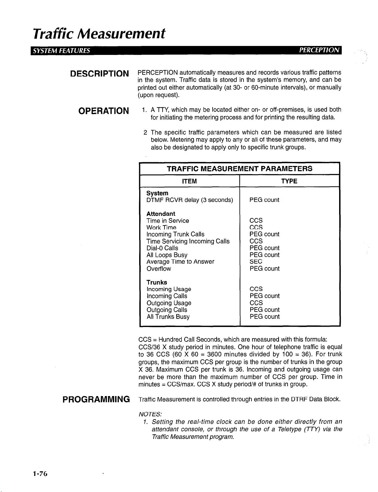
Traffic Measurement
DESCRlPTiON PERCEPTION automatically measures and records various traffic patterns
in the system. Traffic data is stored in the system’s memory, and can be
printed out either automatically (at 30- or 60-minute intervals), or manually
(upon request).
OPERATION
1. A TTY, which may be located either on- or off-premises, is used both
for initiating the metering process and for printing the resulting data.
2 The specific traffic parameters which can be measured are listed
below. Metering may apply to any or all of these parameters, and may
also be designated to apply only to specific trunk groups.
TRAFFIC MEASUREMENT PARAMETERS
ITEM
System
DTMF RCVR delay (3 seconds)
Attendant
Time in Service
Work Time
Incoming Trunk Calls
Time Servicing Incoming Calls
Dial-O Calls
All Loops Busy
Average Time to Answer
Overflow
Trunks
Incoming Usage
Incoming Calls
Outgoing Usage
Outgoing Calls
All Trunks Busy
PEG count
ccs
ccs
PEG count
ccs
PEG count
PEG count
SEC
PEG count
ccs
PEG count
ccs
PEG count
PEG count
TYPE
1-76
CCS = Hundred Call Seconds, which are measured with this formula:
CCS/36 X study period in minutes. One hour of telephone traffic is equal
to 36 CCS (60 X 60 = 3600 minutes divided by 100 = 36). For trunk
groups, the maximum CCS per group is the number of trunks in the group
X 36. Maximum CCS per trunk is 36. Incoming and outgoing usage can
never be more than the maximum number of CCS per group. Time in
minutes = CCS/max. CCS X study period/# of trunks in group.
PROGRAMMING T ff’ M
ra IC easurement is controlled through entries in the DTRF Data Block.
NOTES:
1. Setting the real-time clock can be done either directly from an
attendant console, or through the use of a Teletype (TTY) via the
Traffic Measurement program.
Page 85

2. Traffic data is collected in a set of registers which accumulate data
during each prescribed hour or half-hour reporting interval. The
accumulated data is then automatically transferred to a set of holding
registers, so that it may be printed. After off-loading to the holding
registers, the accumulating registers will reset to zero and will then
begin to collect data for the next report. Each of these registers
actually represents a specific location within the system’s memory
3. A Traffic Measurement printout cannot be performed if a utility
program is currently being utilized. In this case, at the time when the
printout would normally occur, the Teletype will generate a request to
abort the utility program. Once the utility program is aborted, the
traffic measurement report will print.
RELATED FEATURES None.
BENEFITS Traffic Measurement generates information regarding trunk and attendant
usage, which is helpful in determining whether or not a system’s current
configuration fulfills a customer’s particular needs. It is important to the
end-user for assessing the efficiency of the system configuration, and
determining any changes that should be made to the trunking or attendant
console arrangements.
Traffic Measurement
1-77
Page 86

TInk
_‘i
llkan&r Red/ (7imer & Temkation Destihation)
‘\
DESCRIPTION
OPERATION
PROGRAMMING
RELATED FEATURES
BENEFITS
Each trunk in the system can be programmed to have a unique, final,
transfer-recall destination, which can be any system station, the attendant
console, or universal night answer. If a transferred trunk call is not
answered and recalls to the station that transferred it, and the call is then
not answered at that station (after a predetermined amount of
time-designated by Trunk Transfer Recall Timer), it will recall to the final
destination assigned to that trunk.
NOTE: This feature is only available in Versions 0.02 software and
above.
Automatic.
The Trunk Transfer Recall Destination is programmed in the DTRK Data
Block for each trunk.
The Trunk Transfer Recall Destination Timer is programmed in the DSD2
Data Block. It is a system-wide timer for all trunks programmed with a
destination.
1. Direct-in Lines (System).
2. Attendant-Position Electronic/Digital Telephones (DSSDDSS).
Transfer Recall Destination enables the customer to configure a final
answer position for each incoming trunk, ensuring that important calls
always reach someone who can handle them. This capability is especially
valuable in distributed-call-processing applications, in which Direct-in
Lines are terminated on Attendant-Position Electronic/Digital Telephones
or other system’s stations.
l-78
Page 87

Uniform Disfribufion Wiring
DESCRIPTION
OPERATION
PROGRAMMING
RELATED FEATURES
BENEFITS
Uniform Distribution Wiring refers to the ability to prewire a PERCEPTION
installation site with either 2- or 3-pair cable, regardless of the future
configuration of the system. This is enabled both through the system’s
employment of electronic/digital telephones with 2-pair wiring, and through
the system’s non-utilization of conventional button equipment.
None.
None.
NOTE: If a future system configuration is to utilize voice/data transmission
capabilities, then 3-pair cable should be used.
None.
By using the industry standard system and station wiring plan,
PERCEPTION eliminates the end-user expense of installing custom
house wiring.
1-79
Page 88
Universal Night Answer
DESCRlPTlON When the system is in night operation, incoming calls can be programmed
to go to either a night-answer station, or to a Universal Night Answer
device, such as a bell or loud ringer. Any station user can pick up a UNA
call by pressing a m button on the telephone, or by dialing an access
OPERAT’ON
code. In
system. In
per system (tenant Systems only).
o nswer an Incoming Call When the Night Bell Is Heard:
Tl PObtain dial tone.
2. Press the m button, or dial the access code (10) .
3. Speak to the caller.
4. Use Call Transfer to connect the call with the desired station.
Version A
Version D
n You will be connected to the incoming call.
software, one UNA zone can be programmed per
software, up to two UNA zones can be programmed
PROGRAMMING V
RELATED FEATURES
BENEFITS U
ersion A software:
basis. In the DTRK Program, at the NIT and DAY prompts, if you wish the
trunk to ring UNA, enter NONE.
Version D software:
Version A
in the DSYS Program, two additional prompts will appear in this program:
UNAO and UNAl. This is where each UNA zone is assigned to either
tenant 0 (TENO) or tenant 1 (TENI).
NOTE: Night assignments of trunks can be reassigned via the Attendant
Console.
1. Consoleless Operation (System Features).
2. Night Service (System Features).
3. Night Service Control (Attendant Console Features).
niversal Night Answer ensures that incoming calls are answered, even if
the primary answering position is not attended. It enables customers to
reduce the number of personnel required to handle calls during periods of
low staffing, or in applications in which employees are distributed
throughout a facility without permanent stations (such as warehouses, car
dealerships, etc.).
software, with one additional program. If Y was entered to TEN
Programming for UNA is done on an individual-trunk
Programming for UNA is done the same as in
I-80
Page 89

Universal Port Architecture
DESCRIPTION
OPERATION
PROGRAMMING
PERCEPTION e&ex provide great flexibility in station and trunk
configuration. This is inherent in a universal-port system, although there
are a certain number of dedicated slots (for either trunks, stations, and
attendant consoles), the remaining slots can be used for trunk, station, or
data PCBs.
Automatic.
1. Station ports are programmed in either the DEKT or DSTT Data
Block.
2. Trunk ports are programmed in the DTRK Data Block.
3. Data ports are programmed in the DDIU and DMDU Data Block.
NOTES:
1. PERCEPTION II is a dedicated port system. In Version A software
levels, the number of analog/data stations is 720 and the number of
trunks is 32. With Versions D.01 - D.OlD software and the
expansion cabinet, the number of stations increases to 240 and the
number of trunks grows to 64.
2. PERCEPTlONe, which runs on Version D software, is a universalport system. The line/trunk capacity in the basic cabinet is 96 stations
and 0 trunk to a square system of 32 each. With an expansion
cabinet installed, these numbers increase to 192 stations and 0 trunk
to 64 by 64.
3. PERCEPTION,,, which also runs on Version D software, is also a
universal-port system. The line/trunk capacity in the basic cabinet is
128 stations and 32 trunks, or 0 station and 96 trunks. With the first
expansion cabinet installed, these numbers increase to 192 stations
and 48 trunks to 64 stations by 112 trunks. With the second
expansion cabinet installed, these numbers increase again to 255
stations and 64 trunks to 128 stations by 128 trunks.
RELATED FEATURES
BENEFITS
None.
PERCEPTION’s Universal Port Architecture enables it to meet the unique
trunk and station requirements of a wide range of end-users. It also makes
it much easier and much less expensive for users to expand existing
systems, since most available PCB slots in each cabinet will accept either
trunk, station, data, or DSS Console PCBs.
1-81
Page 90

Variable Time-ouf
DESCRIPTION
The various time-out intervals which are used in conjunction with certain
features may be individually altered from their default, standard time-out
values. The time-out periods which allow such alterations are as follows:
1. Timed Reminders (Camp-on/RNA):
a. Camp-on or Call Waiting (COT)-This timer indicates the period
of time that elapses between the time that a call is placed in the
Camp-on/Call Waiting mode, and the time when that call rings
back.
b. Ring-No Answer (RNA)-The RNA time-out setting indicates the
length of time that a call will ring at a station before it will return
for rerouting, message service, etc.
2. Attendant Overflow (AOF)-This setting indicates the length of time
that a call will ring at an attendant console (which has been placed in
Overflow mode) before it is routed to the assigned Overflow station.
3. Call Forward-No Answer (CFD)-The CFD setting determines the
length of time that a telephone will ring, before it will forward to a Call
Forward-No Answer or Call Forward-Busy/No Answer forwarding
destination.
4. Hold/Electronic/Digital Telephone Park (HLD)-The Hold/
Electronic/Digital Telephone Park reminder timer is set to determine
the length of time that a call will remain either on hold (on standard
telephones), or in a Park mode (on electronic/digital telephones),
before that call will ring back to the station at which it is waiting. This
time-out setting also has the option of being turned off completely,
rather than being assigned a timing value.
1-82
5. Dial Pulse Timer (DPT)-The DPT timer applies to rotary and
electronic/digital telephones, and indicates the allowable time
between dialed digits. The attendant must also wait for this timer to
expire after the last digit of a telephone number is dialed, before
putting the call on hold, or dialing additional digits.
6. Push-button Timer (PBT)-The PBT timer also indicates the
allowable time between dialed digits, but applies to ste.ndard pushbutton telephones which are connected to a DTMF receiver.
Specifically, the PBT time allocation denotes the length of time that a
DTMF circuit will be held on line in order to receive digits.
7. Line Lockout (LLO)-This time-out determines the allowable time
between the time that a telephone is taken off-hook, and the time that
dialing is started. It also designates the overall time period which is
allowed for digit dialing.
8. Automatic Callback Reserve Time (ACB)-This timer indicates the
length of time that a system will hold a now-idle call which has been
registered for Automatic Callback at another station. Once the
registered station becomes idle, the system will automatically recall
the registering station. The duration of time, in which the system will
Page 91

Variable Time-out
rering the registering station and simultaneously retain the now-idle
registered call connection, is determined by the AC6 time-out setting.
OPERATION
PROGRAMMING
None.
All of the above time-out periods are programmed in their corresponding
entries of the
maximize at 255 seconds, however, specific stipulations must be adhered
to in order to ensure the correct operation of several of the noted time-out
periods. Refer to the following notes for practical limitations regarding
these specific timers. As noted above, the Hold/Park reminder time-out
also has the option of being completely disconnected.
NOTES:
1. The duration of the Call Forward-No Answer (CFD) time-out period
must be less than the Ring-No-Answer (RNA) time-out, or else a call
will return rather than be forwarded to the registered forwarding
destination.
2. The Automatic Callback (ACB) time-out may be designated a value
of up to six seconds, Although higher time-out values will be
accepted in programming, they will prevent the system from
functioning properly.
3. The DPT time-out should be set at the lowest practical value, since a
two-way-transmit speech path is not obtainable on either a rotary or
electronic/digital telephone until after the DPT time-out elapses.
While the preset default value of the DPT time-out is 15 seconds,
normal operation requires that it be set at between four and six
seconds, although having it set this low may not light Message
Waiting Lights.
4. The PBT time-out value should also be brief, since it determines the
length of time before a two-way speech path is obtainable on a
standard DTMF telephone. The default value of the PBT time-out
period is four seconds, which is a recognized optimum timing value.
DSYS Program.
Available timing values for each time-out
RELATED FEATURES
BENEFITS
1. Line Lockout (System).
2. Tone Dialing-to-Dial Pulse Conversion (System).
3. Timed Reminders-Variable (Attendant).
Variable system timers allow for individual system flexibility and
customization. Available programming options permit the further
customization of a system, since features and their accompanying timeouts can be configured to fit each customer’s unique application
requrrements.
1-83
Page 92

Voice Mail Connection
DESCRlPTlON PERCEPTION has the ability to interface with a voice mail messaging
system to enable the convenient transmission, receipt, and storage of
voice messages. Selected stations are assigned a voice mailbox, which
can be designated as the forwarding destination of a Call Forward
operation, or which can be reached directly so that messages can be left
by callers, or listened to and stored by a mailbox addressee. Access to the
voice mail system (other than automatic access achieved through Call
Forwarding) is achieved through the entrance of specific access and
security codes. A mailbox addressee may also access his or her mailbox
from an off-premises location in order to review any messages which may
have been left.
OPERATION J- L
o eave a Message at a Voice Mailbox:
1. Dial the voice mail port.
2. Dial the mailbox.
To Call Forward to Voice Mail:
1. Dial the access code (i I) .
2. Dial the voice mail port.
3. Dial the mailbox address.
4. Press the 1 button.
To Review a Message Which Has Been Left at Your Mailbox:
1. Dial the voice mail port.
2. Dial the mailbox address.
To Review a Message Which Has Prompted the Message LED to
Light (This Applies Only to Stations Which Have a Message Waiting
Indication):
1. Press the m button.
n The awaiting messages will automatically be retrieved (if the m
button is programmed to do so), and the button’s accompanying
LED will automatically go out after the waiting messages have
been reviewed.
l-84
PROGRAMMING ”
telephone ports may be assigned as voice mail ports in Version A level of
oice mail is programmed in the DMCD Data Block. Eight standard
software, and 32 standard telephone ports may be assigned as voice mail
ports in Version D software levels.
NOTES:
1. When an electronic/digital telephone dials voice mail access digits,
the PERCEPTION system will convert these signals into DTMF
tones, and then send these tones to one of the station ports which
has been assigned to voice mail operation in the DMCD Data Block.
2. Each voice mail port within a voice mail system can be programmed
to provide a message waiting indication to a station whenever a
Page 93

Voice Mail Connection
message has been left at that station’s mailbox. Specifically, if a port
has been assigned this capability, then any message which has been
left through that particular port will automatically light the message
waiting lamp on the telephone of the initially-called station. Any
electronic/digital or standard DTMF telephone which has a
programmed message m button will receive this indication. The
ability for a specific voice mail port to activate the lighting of a
station’s message waiting lamp is made by first entering VM (voice
mail) in response to the MWCO or MWCI prompt within the DMCD
Data Block, and by then entering the directory number of the port
which is to provide this capability
3. If programmed to do so, PERCEPTION will generate an automatic
disconnect signal to the incorporated voice mail system whenever a
connected station or trunk hangs up.
4. The utilization of Tenant Service allows PERCEPTION to have one
message center designated as a voice mail port and the other
specified as the message center, if desired.
5. When dialing a voice mail port, the voice mail system must answer
the call before PERCEPTION will outpulse any digits. This forces the
user to wait for an answer before resuming digit dialing.
6. A.06B software is the first level of Version D software that enables
up to 32 ports at the TVMO/TVMl prompts in the DMCD Program.
Version D.OlC software enables 32 ports to be entered at the
MDNO/MDNI prompts in the DMCD Program.
RELATED FEATURES
BENEFITS ”
1. Station Hunting (Station).
2. Automatic Dialing (Electronic/Digital Telephone).
4. Message Waiting (Station).
5. Call Forward-All types (Station and System).
6. Speed Dial-System (Attendant).
7. Direct Inward Dialing (System).
8. Direct-in Line (System).
oice Mail Integration enables the customer to integrate virtually any voice
mail/automated attendant system, using in-band signaling, into a
PERCEPTION system. Voice Mail ensures that important information is
not lost when a called party cannot take the call, and it greatly improves
employee productivity. An automated attendant simplifies call processing,
and it can reduce the need for additional manpower. Frequently, an
automated attendant can be incorporated into a call processing
arrangement that also includes attendant consoles and attendant-position
electronic/digital telephones. This feature greatly enhances the customer’s
ability to configure call processing arrangements that satisfy unique
application requirements.
l-85
Page 94

PERCEPTION
eaex
l/II
Attendant Console
Features
Issue 2, February
Section 200-255-640
1992
Page 95

Table of Contents
FEATURE
Attendant Camp-on/Call Waiting.. ....................................................................................................
Attendant Conference.. ....................................................................................................................
Attendant Emergency Transfer.. ......................................................................................................
Attendant Hold .................................................................................................................................
Attendant Initialization.. ....................................................................................................................
Attendant Recall ..............................................................................................................................
Busy Lamp Field ..............................................................................................................................
Call Forward Cancel ........................................................................................................................
Call Waiting Lamp.. ..........................................................................................................................
Call Waiting Lamp Signaling.. ..........................................................................................................
Digital Information Display.. .............................................................................................................
Direct Access to Paging.. .................................................................................................................
Incoming Call Identification.. ............................................................................................................
Incoming Call Priority.. .....................................................................................................................
Individual Trunk Access.. .................................................................................................................
Interposition Call Transfer.. ..............................................................................................................
Join ..................................................................................................................................................
Lockout ............................................................................................................................................
Meet-Me Page .................................................................................................................................
Message Waiting .............................................................................................................................
Night Service Control.. .....................................................................................................................
Non-delayed Operation.. ..................................................................................................................
Overflow Facility ..............................................................................................................................
Position Busy.. .................................................................................................................................
Push-button Dialing .........................................................................................................................
Secrecy.. ..........................................................................................................................................
Serial Call (Business Console Only). ...............................................................................................
Speed Dialing-System .....................................................................................................................
Splitting ............................................................................................................................................
Station Number Display.. .................................................................................................................
Switched Loop Termination.. ............................................................................................................
Through Dialing ...............................................................................................................................
Timed Recall-Variable.. ....................................................................................................................
Time-of-Day Display, Set, Reset.. ....................................................................................................
Trunk Equipment Number Display.. .................................................................................................
Trunk Group Access Control.. ..........................................................................................................
Trunk Group Busy Indication ...........................................................................................................
Trunk-to-Trunk Connections ............................................................................................................
Variable Attendant Console Loop Buttons.. .....................................................................................
Verification (Station & Trunk) ...........................................................................................................
PAGE
4-l
4-4
4-7
4-8
4-9
4-10
4-l 1
4-12
4-13
4-14
4-15
4-17
4-19
4-20
4-21
4-22
4-23
4-25
4-27
4-29
4-31
4-34
4-35
4-38
4-39
4-40
4-41
4-42
4-43
4-45
4-46
4-48
4-49
4-50
4-52
4-53
4-55
4-56
4-58
4-62
FIGURE LIST
FIGURE
1 Attendant Console With Four m Buttons.. ....................................................................... 4-59
2 Attendant Console With Six m Buttons.. ......................................................................... 4-60
3 Attendant Console With Eight m Buttons.. ...................................................................... 4-60
SUBJECT PAGE
4-i
Page 96

Attendant Camp-on/Cal/ Waiting
DESCRIPTION
OPERATION
Attendant Camp-on/Call Waiting enables any incoming trunk call, which
has been extended to a busy station by an attendant, to be held in queue
until the called station becomes idle. When Camp-on/Call Waiting is
registered, the busy station will hear either a single tone for Camp-on, or a
double tone for Call Waiting to indicate the waiting call. If an incoming call
remains camped-on to a busy line, or sits in the Call Waiting queue for a
period longer than the system’s set Camp-on/Call Waiting time-out period,
the call will return to the attendant console.
1. Dial the directory number.
The EXCL SRC LED will light steadily when the first digit is
dialed, and the voice path to the caller will be broken.
The DEST directory number will be displayed as the digits are
dialed, and STATUS will display BSY.
If you hear nothing (Camp-on), go to Step 2.
If you hear ringing tone (Call Waiting), go to Step 4A.
If you hear busy tone, go to Step 3B (busy tone indicates that
Camp-on/Call Waiting is not possible for one of the following
reasons):
a. Camp-on/Call Waiting is not permitted due to system
restrictions.
b. The called station is either in a conference call, on hold, or
ringing.
2. Press the mm button.
n The EXCL DEST LED will light, the EXCL SRC LED will go out,
and you will now have a voice connection with the caller.
PROGRAMMING
3A. If the caller wants to wait:
4A. Press the m button.
n The LPK LED and all displays will go out, the RLS LED will light,
and the console will become idle.
NOTE: If the call remains unanswered for ( ) seconds, the call will be
returned to your console as a Timed Recall.
3B. If the caller does not want to wait, or if Camp-on is not allowed:
4B. Press the mww button.
H The called station will be released from the console, the DEST
display will clear, and if requested, another DN can now be
dialed.
5B. Press the m button.
H The LPK LED and all displays will go out, the RLS LED will light,
and the console will become idle.
1. See Notes 1 and 5.
2. The Camp-on/Call Waiting time-out period is assigned in the COT
entry of the DSYS Data Block.
4-1
Page 97
Attendant Camp-on/Call Waiting
NOTES:
1. Camp-on and Call Waiting are mutually exclusive. If Call Waiting is
denied by the station’s COS, Camp-on will automatically be applied.
2. Station Hunting overrides both Camp-on and Call Waiting. However,
if all directory numbers that are assigned to a particular hunting group
are busy Camp-on will occur.
3. If the station which has been camped-on to is an electronic/digital
telephone, the Camp-on/Call Waiting warning tone will sound over
the stations speaker. If the station is a standard telephone, the tone
will sound over the station handset. Any voice announcement that is
currently being received, when a station is called, will be interrupted
for the duration of the warning tone (0.5 second).
4. The attendant console will receive the following visual and audible
indications for timed recalls:
a, No Answer Condition (Ring No Answer).
n ICI = TIM
n Loop = 60 IPM flash
n Status = RNG
n Console = Buzz tone sounds
H SRC = Calling trunk number
n DEST = Called DN
(When the attendant answers the recall, the LPK LED indication
will light steadily and the buzz tone will stop).
b. Busy Condition (Camp-on/Call Waiting).
n ICI = TIM
H Loop = 60 IPM flash
n Status = BSY
n Console = Buzz tone sounds
n SRC = Calling trunk number
n DEST = Called DN
(When the attendant answers the recall, the LPK LED indication
will light steadily and the buzz tone will stop).
5. If the called station is programmed for Warning Tone-Denied (WTA =
N in DEKT/DSTT Data Blocks), the tone interruption will not be
provided to the called station. Camp-on operation, however, will still
be activated.
6. Camp-on/Call Waiting does not apply to unanswered station-tostation calls. This includes calls made to/from handsfree answerback
stations.
7. If a station is programmed for Warning Tone-Denied, Call Waiting will
not occur, and Camp-on will be applied.
8. An unlimited number of calls can be camped-on to a single station by
an attendant. Only one call can sit in the Call Waiting queue.
RELATED FEATURES
4-2
1. Music-on-Hold and Camp-on (System).
2. Night Service (System).
3. Call Waiting (Station).
4. Hunting (Station).
5. Uninterrupted Line Connections (Station).
6. Handsfree Answerback with Speaker Cut-Off (Electronic/Digital
Telephone).
Page 98

A ttenciant Camp-on/Gail Waiting
BENEFITS Attendant Camp-on enables an attendant to place an incoming call in
queue for a busy station, and gives the attendant the freedom to receive
and place other calls. Camp-on also ensures that station users will not
miss important incoming calls.
4-3
Page 99

Attendant Conference
DESCRIPTION
OPERATION T
An attendant can set up a conference call for as many as five people
(including a maximum of two trunks) plus the attendant, at the request of
either a station user or an outside caller. The starting point for a
conference can be any of the following conditions:
n The console has answered an incoming call from a station or trunk,
and that party is to be the first member of the conference.
n The console dials the first conference member on an m button in
the usual manner.
w Due to an Attendant Recall, the console has a three-way connection
on an [a3 button. The attendant must establish a three-way voice
connection through a second operation of the m button prior to
proceeding to step 1.
o use Attendant Conference, a station user or trunk party calls the
attendant, who then establishes all conference connections. An attendant
conference is set up by adding one party at a time. It can be initiated in the
following ways:
To Establish a Conference Call After a Station or Trunk Calls the
Attendant:
1. The attendant presses the m button.
H The LPK LED will remain steadily lit.
The CONF LED will flash.
n
The COS display will show 01 (the number of conferees).
n
2. The attendant dials the second party (on the same LPK) and, when
the call is answered, presses the m button again.
A conference will now exist between the first and second parties,
E
and the attendant.
n The COS display will show 02.
3. The attendant may then dial the third patty.
n When the first digit is pushed, the console will drop out of the
conference, leaving parties #l and #2 connected.
n The CONF LED will now light steadily.
n When party #3 answers, the party can be added to the
conference by pressing the m button.
A four-party conference (including the attendant) will now exist.
n
The COS display will show 03.
4
4. Up to two additional parties may be added in the same manner.
The COS display will show 05.
n
5. When the conference is complete, the attendant presses the m
button in order to remove the console from the conference.
n The CONF LED will now light steadily.
6. The attendant may reenter an established conference at any time by
pressing the m and m buttons. When this is done:
n The CONF LED will flash.
A warning tone (440 Hz 1 -second burst) will signal the conference
n
members that the attendant is about to reenter the conference.
n The attendant will not hear the warning tone.
4-4
Page 100

Attendant Conference
To Transfer a Two-party Connection (Established on an m Button)
to an Attendant Conference:
1. The attendant presses the m button.
n The CONF LED will flash.
W The LPK LED will remain steadily lit.
NOTE: The two parties will now be the first two parties in a conference.
Additional parties may be added by following the previously-mentioned
steps.
To Initiate a Conference Call by an Attendant:
1. The attendant presses an m button.
H The LPK LED will light steadily.
H The CONF LED will flash.
2. The attendant now dials the first party, and when the call is answered,
presses the m button.
n Additional parties may be added to the conference by following
the previously-mentioned steps.
NOTES:
1. If an attendant attempts to establish a conference call consisting of
more than five parties (in addition to the console itself), the overflow
tone will return to the attendant. This tone may be canceled by
pressing the mrd button
2. If an attendant dials a number that is either busy or is not answered,
the attendant may release the dialed connection by pressing the
mrd button. This will return the console to the conference.
3. The attendant may be recalled to an established conference, either
by a hookflash (standard telephone), or via the m button
(electronic/digital telephone). When this occurs:
a. The CONF and LPK LEDs will flash at 60 /PM.
6. The console buzzer will sound.
c. When the attendant answers with an m button:
H The console buzzer will stop.
n The CONF and LPK LEDs will light steadily
n No warning tone will sound to the established conference
members.
d. The attendant will now be connected only to the recalling party
member. The other parties will remain in conference with each
other.
4. Transmission performance in a conference is designed for a
maximum of two trunks. Additional trunks may be conferenced,
however, transmission may be impaired (amplification is not provided
by Attendant Conference).
5. Certain trunks will not release automatically from a conference.
Therefore, the attendant must either break in occasionally, or ask one
of the conferring stations to call once the conference is finished. The
release capability must be determined locally on a case-by-case
basis.
6. Paging trunks cannot be conferenced.
4-5
 Loading...