

Page 1

E6581343 ③
TOSVERT VF-AS1/PS1
PROFIBUS-DP Option Function Manual
PDP002Z
* The data given in this manual are subject to change without notice.
© Toshiba Schneider Inverter Corporation
All rights reserved.
2006
Page 2

E6581343 ③
Contents
1. Introduction...............................................................................................................................................2
2. Connection Information ............................................................................................................................3
2.1. Exterior features...........................................................................................................................3
2.2. PDP002Z Device Data.................................................................................................................4
2.3. Setting a station address .............................................................................................................5
2.4. Status indicator ............................................................................................................................7
2.5. Communications-related parameters...........................................................................................7
3. “PROFIdrive” Profile .................................................................................................................................8
3.1. PPO TYPE ...................................................................................................................................8
3.2. STW Control Word Data ..............................................................................................................9
3.3. ZSW Status Word Data..............................................................................................................10
3.4. State Macine ..............................................................................................................................11
3.4.1. Examples of driving by the State Machine.........................................................................12
3.5. The Access to the PROFIBUS parameter .................................................................................13
3.5.1. Examples of reading or changing the PROFIdrive parameter ...........................................15
3.6. Access to the VF-AS1/PS1 parameter ......................................................................................17
3.6.1. Examples of reading or changing the VF-AS1/PS1 parameter .........................................17
4. ”USER DEFIND” Profile .........................................................................................................................19
4.1. How to use .................................................................................................................................20
4.2. The overview of the VF-AS1/PS1 parameter.............................................................................21
4.2.1. FA06 (Command word 1 from internal option PCB) ..........................................................21
4.2.2. FA23 (Command word 2 from internal option PCB) ..........................................................21
4.2.3. FA07 (Frequency reference from internal option PCB) .....................................................22
4.2.4. FA33 (Torque reference from internal option PCB) ...........................................................22
4.2.5. FA50 (Terminal output data from comm.) ..........................................................................22
4.2.6. FA51 (Analog output (FM) data from comm.) ....................................................................22
4.2.7. FA52 (Analog output (AM) data from comm.) ....................................................................22
4.2.8. FD01 (Inverter status (real time)).......................................................................................23
4.2.9. FD00 (Output frequency (real time)) ..................................................................................23
4.2.10. FD03 (Output current (real time)).......................................................................................23
4.2.11. FE36 (Analog input value VI/II) ..........................................................................................24
4.2.12. FE37 (RX Input) .................................................................................................................24
4.2.13. FE60 - FE63 (My Monitor)..................................................................................................24
4.2.14. FE14 (Cumulative run time) ...............................................................................................24
4.2.15. FE40 (Analog output (FM)) ................................................................................................24
4.2.16. FC91 (Alarm code).............................................................................................................25
4.2.17. FD06 (Input TB Status) ......................................................................................................25
4.2.18. FD07 (Output TB Status) ...................................................................................................25
4.2.19. FC90, FE10 - FE13 (Inverter fault).....................................................................................26
4.3. About GSD file ...........................................................................................................................27
- 1 -
- 1/27 -
Page 3

1. Introduction
Thank you for purchasing the PROFIBUS-DP option “PDP002Z” for the VF-AS1/PS1.
Before using the PROFIBUS-DP option, please familiarize yourself with the product and
be sure to thoroughly read the instructions and precautions contained in this manual.
In addition, please make sure that this manual and “Instruction Manual” is delivered to the
end user, and keep this function manual in a safe place for future reference or
drive/interface inspection.
This manual describes the supported functions for the “PDP002Z”.
In conjunction with this manual, the following manuals are supplied by Toshiba, and they
are essential both for ensuring a safe, reliable system installation as well as for realizing
the full potential of the “PDP002Z”:
- TOSVERT VF-AS1 Instruction Manual ..................................E6581301
E6581442(for WN1/WP1)
- TOSVERT VF-PS1 Instruction Manual ..................................E6581386
- PDP002Z Instruction Manual (Installation, Wiring, etc.)......... E6581279
E6581343 ③
- 2 -
Page 4
2. Connection Information
This option allows the VF-AS1/PS1 inverter to be communicated with the cyclic command
transmission and monitoring of the original profile ("USER DEFIND", refer to page 19) of
our company other than application profile "Profile for Variable Speed Drives PROFIdrive
(3.072), refer to page 8" which PROFIBUS defines.
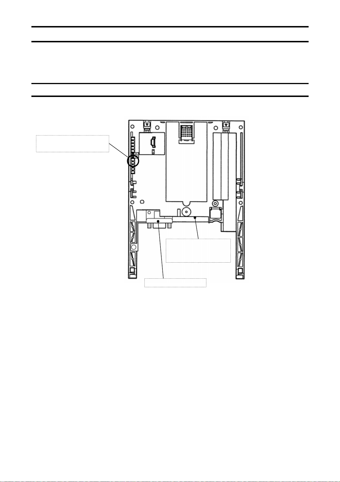
2.1. Exterior features
Status LED indicator
(Refer to Section 2.4)
PROFIBUS connector
E6581343 ③
Address
setting Dip switch
(Refer to Section 2.3)
- 3 -
Page 5

2.2. PDP002Z Device Data
Parameter Value Note
Vendor_Name "TSIJ" Model_Name "PDP002Z" Revision "V1.1" Ident_Number 0x093C ID number
Protocol_Ident 0 PROFIBUS-DP
Station_Type 0 DP slave
FMS_supp 0 PROFIBUS-FMS: not supported
Hardware_Release "V1.0" Software_Release "V1.0" -
9.6_supp 1 9.6kbps: supported
19.2_supp 1 19.2kbps: supported
45.45_supp 1 45.45kbps: supported
93.75_supp 1 93.75kbps: supported
187.5_supp 1 187.5kbps: supported
500_supp 1 500kbps: supported
1.5M_supp 1 1.5Mbps: supported
3M_supp 1 3Mbps: supported
6M_supp 1 6Mbps: supported
12M_supp 1 12Mbps: supported
MaxTsdr_9.6 60 60 bit tiime
MaxTsdr_19.2 60 60 bit tiime
MaxTsdr_45.45 250 250 bit tiime
MaxTsdr_93.75 60 60 bit tiime
MaxTsdr_187.5 60 60 bit tiime
MaxTsdr_500 100 100 bit tiime
MaxTsdr_1.5M 150 150 bit tiime
MaxTsdr_3M 250 250 bit tiime
MaxTsdr_6M 450 450 bit tiime
MaxTsdr_12M 800 800 bit tiime
Redundancy 0 not supported
Repeater_Ctrl_Sig 2 TTL level
24V_Pins 0 not used
Freeze_Mode_supp 1 supported
Sync_Mode_supp 1 supported
Set_Slave_Add_Supp 0 not supported
Auto_Baud_supp 1 supported
Min_Slave_Intervall 1 0.1ms
Fail_Safe 0 mode: not supported
Modular_Station 1 Max_Module 1 ID: 1 byte
Max_Input_len 20 Input: 20 bytes
Max_Output_len 20 Output: 20 butes
Max_Data_len 40 Data length: 40 bytes
User_Prm_Data_Len 2 Max_User_Prm_Data_Len 2 -
E6581343 ③
- 4 -
Page 6
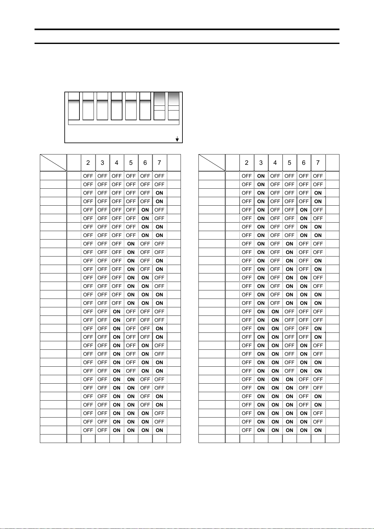
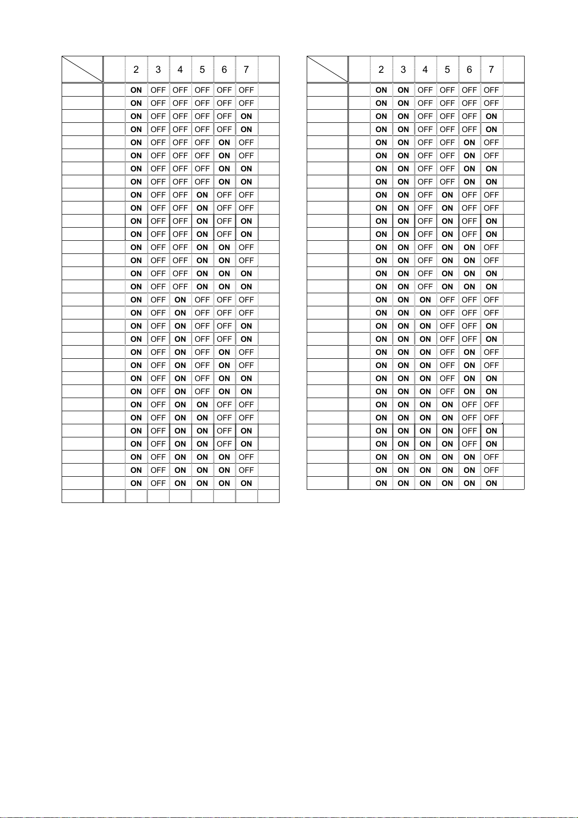
2.3. Setting a station address
The DIP switch on the circuit board of the option is used to set a station address. Each
DIP switch is ON when it is flipped to the lower position. By default, it is
factory-configured to 2.
The station address must be unique and not match any other device on the network.
1 2 3 4 5 6 7 8
DIP ON
SW
ID
OFF OFF OFF OFF OFF OFF OFF OFF
0
OFF OFF OFF OFF OFF OFF OFF ON
1
OFF OFF OFF OFF OFF OFF ON OFF
2
OFF OFF OFF OFF OFF OFF ON ON
3
OFF OFF OFF OFF OFF ON OFF OFF
4
OFF OFF OFF OFF OFF ON OFF ON
5
OFF OFF OFF OFF OFF ON ON OFF
6
OFF OFF OFF OFF OFF ON ON ON
7
OFF OFF OFF OFF ON OFF OFF OFF
8
OFF OFF OFF OFF ON OFF OFF ON
9
OFF OFF OFF OFF ON OFF ON OFF
10
OFF OFF OFF OFF ON OFF ON ON
11
OFF OFF OFF OFF ON ON OFF OFF
12
OFF OFF OFF OFF ON ON OFF ON
13
OFF OFF OFF OFF ON ON ON OFF
14
OFF OFF OFF OFF ON ON ON ON
15
OFF OFF OFF ON OFF OFF OFF OFF
16
OFF OFF OFF ON OFF OFF OFF ON
17
OFF OFF OFF ON OFF OFF ON OFF
18
OFF OFF OFF ON OFF OFF ON ON
19
OFF OFF OFF ON OFF ON OFF OFF
20
OFF OFF OFF ON OFF ON OFF ON
21
OFF OFF OFF ON OFF ON ON OFF
22
OFF OFF OFF ON OFF ON ON ON
23
OFF OFF OFF ON ON OFF OFF OFF
24
OFF OFF OFF ON ON OFF OFF ON
25
OFF OFF OFF ON ON OFF ON OFF
26
OFF OFF OFF ON ON OFF ON ON
27
OFF OFF OFF ON ON ON OFF OFF
28
OFF OFF OFF ON ON ON OFF ON
29
OFF OFF OFF ON ON ON ON OFF
30
OFF OFF OFF ON ON ON ON ON
31
1 2 3 4 5 6 7 8
SW
ID
32
33
34
35
36
37
38
39
40
41
42
43
44
45
46
47
48
49
50
51
52
53
54
55
56
57
58
59
60
61
62
63
E6581343 ③
1 2 3 4 5 6 7 8
OFF OFF ON OFF OFF OFF OFF OFF
OFF OFF ON OFF OFF OFF OFF ON
OFF OFF ON OFF OFF OFF ON OFF
OFF OFF ON OFF OFF OFF ON ON
OFF OFF ON OFF OFF ON OFF OFF
OFF OFF ON OFF OFF ON OFF ON
OFF OFF ON OFF OFF ON ON OFF
OFF OFF ON OFF OFF ON ON ON
OFF OFF ON OFF ON OFF OFF OFF
OFF OFF ON OFF ON OFF OFF ON
OFF OFF ON OFF ON OFF ON OFF
OFF OFF ON OFF ON OFF ON ON
OFF OFF ON OFF ON ON OFF OFF
OFF OFF ON OFF ON ON OFF ON
OFF OFF ON OFF ON ON ON OFF
OFF OFF ON OFF ON ON ON ON
OFF OFF ON ON OFF OFF OFF OFF
OFF OFF ON ON OFF OFF OFF ON
OFF OFF ON ON OFF OFF ON OFF
OFF OFF ON ON OFF OFF ON ON
OFF OFF ON ON OFF ON OFF OFF
OFF OFF ON ON OFF ON OFF ON
OFF OFF ON ON OFF ON ON OFF
OFF OFF ON ON OFF ON ON ON
OFF OFF ON ON ON OFF OFF OFF
OFF OFF ON ON ON OFF OFF ON
OFF OFF ON ON ON OFF ON OFF
OFF OFF ON ON ON OFF ON ON
OFF OFF ON ON ON ON OFF OFF
OFF OFF ON ON ON ON OFF ON
OFF OFF ON ON ON ON ON OFF
OFF OFF ON ON ON ON ON ON
- 5 -
Page 7
E6581343 ③
SW
ID
64
65
66
67
68
69
70
71
72
73
74
75
76
77
78
79
80
81
82
83
84
85
86
87
88
89
90
91
92
93
94
95
1 2 3 4 5 6 7 8
OFF ON OFF OFF OFF OFF OFF OFF
OFF ON OFF OFF OFF OFF OFF ON
OFF ON OFF OFF OFF OFF ON OFF
OFF ON OFF OFF OFF OFF ON ON
OFF ON OFF OFF OFF ON OFF OFF
OFF ON OFF OFF OFF ON OFF ON
OFF ON OFF OFF OFF ON ON OFF
OFF ON OFF OFF OFF ON ON ON
OFF ON OFF OFF ON OFF OFF OFF
OFF ON OFF OFF ON OFF OFF ON
OFF ON OFF OFF ON OFF ON OFF
OFF ON OFF OFF ON OFF ON ON
OFF ON OFF OFF ON ON OFF OFF
OFF ON OFF OFF ON ON OFF ON
OFF ON OFF OFF ON ON ON OFF
OFF ON OFF OFF ON ON ON ON
OFF ON OFF ON OFF OFF OFF OFF
OFF ON OFF ON OFF OFF OFF ON
OFF ON OFF ON OFF OFF ON OFF
OFF ON OFF ON OFF OFF ON ON
OFF ON OFF ON OFF ON OFF OFF
OFF ON OFF ON OFF ON OFF ON
OFF ON OFF ON OFF ON ON OFF
OFF ON OFF ON OFF ON ON ON
OFF ON OFF ON ON OFF OFF OFF
OFF ON OFF ON ON OFF OFF ON
OFF ON OFF ON ON OFF ON OFF
OFF ON OFF ON ON OFF ON ON
OFF ON OFF ON ON ON OFF OFF
OFF ON OFF ON ON ON OFF ON
OFF ON OFF ON ON ON ON OFF
OFF ON OFF ON ON ON ON ON
SW
ID
96
97
98
99
100
101
102
103
104
105
106
107
108
109
110
111
112
113
114
115
116
117
118
119
120
121
122
123
124
125
126
1 2 3 4 5 6 7 8
OFF ON ON OFF OFF OFF OFF OFF
OFF ON ON OFF OFF OFF OFF ON
OFF ON ON OFF OFF OFF ON OFF
OFF ON ON OFF OFF OFF ON ON
OFF ON ON OFF OFF ON OFF OFF
OFF ON ON OFF OFF ON OFF ON
OFF ON ON OFF OFF ON ON OFF
OFF ON ON OFF OFF ON ON ON
OFF ON ON OFF ON OFF OFF OFF
OFF ON ON OFF ON OFF OFF ON
OFF ON ON OFF ON OFF ON OFF
OFF ON ON OFF ON OFF ON ON
OFF ON ON OFF ON ON OFF OFF
OFF ON ON OFF ON ON OFF ON
OFF ON ON OFF ON ON ON OFF
OFF ON ON OFF ON ON ON ON
OFF ON ON ON OFF OFF OFF OFF
OFF ON ON ON OFF OFF OFF ON
OFF ON ON ON OFF OFF ON OFF
OFF ON ON ON OFF OFF ON ON
OFF ON ON ON OFF ON OFF OFF
OFF ON ON ON OFF ON OFF ON
OFF ON ON ON OFF ON ON OFF
OFF ON ON ON OFF ON ON ON
OFF ON ON ON ON OFF OFF OFF
OFF ON ON ON ON OFF OFF ON
OFF ON ON ON ON OFF ON OFF
OFF ON ON ON ON OFF ON ON
OFF ON ON ON ON ON OFF OFF
OFF ON ON ON ON ON OFF ON
OFF ON ON ON ON ON ON OFF
- 6 -
Page 8

E6581343 ③
2.4. Status indicator
The PDP002Z has two LEDs, ST (status) and DX (data exchange) to indicate the
statuses of PROFIBUS-DP and the PDP002Z itself.
ST (Status): Red LED
LED Meanings
ST
DX
MNS
MNS
MNS
Off No diagnostics present
Flashes Waiting for parameterisation or configuration
Lights
DX (Data exchange): Green LED.
Indicates the status of the PROFIBUS network.
It lights when the PDP002Z is on-line and data exchange is possible.
DP status error
* For example, a station address is not setcorrectly.
2.5. Communications-related parameters
Parameter Function Adjustment range Default setting
f830* Communication
option setting 1
(PPO TYPE)
f831
f846
f851 Inverter operation at
f852 Preset speed
f853 Monitoring of
f854** Monitoring of
Communication option
setting 2 - 13
the communications
loss action
(Network wire breaks)
operation selection
communication
device station
address
communications
device’s baud rate
* When the parameters are changed, the power must be cycled to the VF-AS1/PS1 for
the changes to take effect.
** The baud rate of the PDP002Z is automatically set by configuration a baud rate for the
master.
0: None
1: PPO TYPE 1
2: PPO TYPE 2
3: PPO TYPE 3
4: PPO TYPE 4
Refer to section 4. 0
0: Stop and break of connection
1: None
2: Deceleration stop
3: Coast stop
4: Emergency stop
5: Preset speed operation command
(Operating at the preset speed operation
frequency set with f852)
0: None
1 to 15: Preset speed
Displays the station address assigned with the
DIP switch.
0 to 125
Displays the network communication speed set
with the DIP switch.
0: 12 Mbit/s
1: 6 Mbit/s
2: 3 Mbit/s
3: 1.5 Mbit/s
4: 500 kbit/s
5: 187.5 kbit/s
6: 93.75 kbit/s
7: 45.45 kbit/s
8: 19.2 kbit/s
9: 9.6 kbit/s
255: Disabled
0
0
0
2
0
- 7 -
Page 9

3. “PROFIdrive” Profile
3.1. PPO TYPE
The PPO type of PDP002Z is set up by this parameter.
The PROFIBUS-DP protocol uses so-called PPOs (Parameter/Process Data Objects) in
cyclic communication. The figures below show the PPO types and configurations that the
PDP002Z supports
PKW PZD
PKE IND PWE
PPO TYPE 1: Octet-String 12
PPO TYPE 2: Octet-String 20
PPO TYPE 3: Octet-String 4
PPO TYPE 4: Octet-String 12
PKW: Parameter ID/value
PZD: Process Data, cyclically transferred
PKE: Parameter ID (1st and 2nd octet)
IND: Sub-index (3rd octet), 4th octet is reserved
PWE: Parameter value (5th until 8th octet)
STW: Control word
HSW: Main setpoint
ZSW: Status word
HIW: Main actual value
* There are some by which a high byte / low byte is conversely treated depending on a master.
.
E6581343 ③
PZD1
STW
ZSW
PZD2
HSW
HIW
PZD3 PZD4 PZD5 PZD6
- 8 -
Page 10

3.2. STW Control Word Data
g
PDP002Z supports only speed control mode.
Bit Value Name Note
E6581343 ③
0
1
2
3
4
5
6
1
0
1
0
1
0
1
0
1
0
1
0
1
0
ON
OFF 1 Normal stop.
Operating condition
OFF 2 Coast stop.
Operating condition
OFF 3 Emergency Stop.
Operation
Inhibit operation Normal stop.
Operation condition No function.
Inhibit ramp-function No function.
Enable ramp-function No function.
Stop ramp-function No function.
Enable setpoint Drive can be started if all other start conditions are fulfilled.
inhibit setpoint Reference frequency is set to zero.
Drive can be started if all other start conditions are fulfilled.
Drive can be started if all other start conditions are fulfilled.
Drive can be started if all other start conditions are fulfilled.
Drive can be started if all other start conditions are fulfilled.
7
8
9
10
11
-
15
1
0
1
0
1
0
1
0
----
Acknowledge Fault reset (0 -> 1)
No meaning No function.
Inching 1 ON Inverter drives with jogging speed.
Inching 1 OFF
Inching 2 ON No function.
Inching 2 OFF No function.
Control from
the automation unit
No control
Device-specification (Reserved.)
Jogging stop, if "inching 1" was previously ON. Stop drive
accordin
The control word and frequency setpoint (from Profibus) are
activated.
The control word and frequency setpoint (from Profibus) are
not valid.
to inverter setting parameter.
- 9 -
Page 11

3.3. ZSW Status Word Data
Bit Valur Name Note
E6581343 ③
0
1
2
3
4
5
6
1
0
1
0
1
0
1
0
1
0
1
0
1
0
Ready to switch-on Control word bit 0 = 0 and bit1, 2, 10 are set to 1.
Not ready switch-on
Ready Refer to control word, bit 0.
Not ready -
Operating enabled Refer to control word, bit 3.
Operation inhibited -
Fault Inverter is faulted.
Fault-free Inverter is not tripped.
No OFF 2 -
OFF 2 "OFF 2" command present
No OFF 3 -
OFF 3 "OFF 3" command present
Switch-on inhibit
No switch-on inhibit -
Control word bit 0 = 0, 1, 2 or 10 are set to 0,
or the inverter is tripped.
Control word bit1 or 2 is set to 0
or fault trip has been acknowledged.
1
Alarm
7
No alarm Alarm not present or alarm has disappeared again
Setpoint / actual value
As above, but not
in the tolerance range
Control request
8
0
1
0
1
monitoring in the tolerance
9
0
1
Local operation Control only possible on the VF-AS1/PS1.
f or n reached
10
0
11 ----
12 ----
13 ----
14 ----
15 ----
*Bit 11 - 15 are the ON/OFF status monitor of each terminals.
f or n fallen below -
Device-specification
OUT1 terminal monitor
Device-specification
OUT2 terminal monitor
Device-specification
FL terminal monitor
Device-specification
OUT3 terminal monitor
Device-specification
OUT4 terminal monitor
Drive still operational: Alarm in service parameter: No
acknowledgement.
Run command or frequency setting is valid
via Profibus.
Actual value = comparison value (at reference),
set via the parameter number
OUT1 output terminal monitor
(bit 0 of fd07. Function selection: f130)
OUT2 output terminal monitor
(bit 1 of fd07. Function selection: f131)
FL output terminal monitor
(bit 2 of fd07. Function selection: f132)
OUT3 output terminal monitor
(bit 3 of fd07. Function selection: f133)
OUT4 output terminal monitor
(bit 3 of fd07. Function selection: f134)
-
-
- 10 -
Page 12

3.4. State Macine
A
MAINS OFF
A B
OPERATION
INHIBIT
from any state
OFF1
ACTIVE
Power ON
CW: Bit3 = 0
SW: Bit2 = 0
Operation inhibited
CW: Bit0 = 0
SW: Bit1 = 0
Normal Stop
Frequency = 0
CW: Control Word
ST: Status Word
: Status
SWITCH-ON
NOT READY TO
SWITCH-ON
SWITCH-ON
OPERATION
OPERATING
B
INHIBIT
CW: Bit0 = 0
CW: xxxx xxxx xxxx x110
READY TO
CW: xxxx xxxx xxxx x111
READY TO
OPERATE
CW: Bit3 = 1
ENABLE
CW: Bit6 = 1 and Bit10 = 1
SW: Bit6 = 1
SW: Bit0 = 1
SW: Bit1 = 1
from any state
CW: Bit2 = 0
OFF3
ACTIVE
Frequency = 0
SW: Bit2 = 1
SW: Bit9 = 1
E6581343 ③
from any state
FAULT
FAULT
0 -> 1
from any state
SW: Bit5 = 0
Emergency Stop Coast stop
INCHING
ACTIVE
INCHING
PAUSE
OFF2
ACTIVE
CW: Bit6 = 0
CW: Bit8 = 1
Inching ON
CW: Bit8 = 0
Inching OFF
Frequency = 0
and inching pause expired
SW: Bit3 = 1
CW: Bit7 = 1
CW: Bit1 = 0
SW: Bit4 = 0
- 11 -
Page 13

3.4.1. Examples of driving by the State Machine
When using the PROFIdrive profile, the frequency reference is set to HSW. The setting
value “0x0000” - ”0x4000” is equivalent to ”0” - ”Base frequency (parameter vl)”.
When the reverse operation, the frequency reference is set with two's complement of the
forward frequency reference.
During running, HIW shows a output frequency.
3.4.1.1. Example 1. 60Hz Forward running and Deceleration stop
Set ”0x4000” to HSW and the following is set to STW in order.
① 0000 0100 0000 0110 (= 0x0406)
“READY TO SWITCH-ON”
② 0000 0100 0000 0111 (= 0x0407)
“READY TO OPERATE”
③ 0000 0100 0100 1111 (= 0x044F)
“OPERATION”
④ 0000 0100 0100 1110 (= 0x044E)
“OFF1 ACTIVE (Normal Stop)”
3.4.1.2. Example 2. 30Hz Reverse running
When the reverse operation, “0xE000” is set to HSW. “0xE000” is two's complement of
the “0x2000” as the forward frequency reference 30Hz.
The Setup to STW is same as the Example 1.
3.4.1.3. Example 3. Inching and pause
the following is set to STW in order.
① 0000 0100 0000 0110 (= 0x0406)
“READY TO SWITCH-ON”
② 0000 0100 0000 0111 (= 0x0407)
“READY TO OPERATE”
③ 0000 0101 0000 1111 (= 0x050F)
“INCHING ACTIVE”
④ 0000 0100 0100 1111 (= 0x040F)
“INCHING PAUSE”
* The inching frequency is according to the parameter f260 on VF-AS1/PS1.
E6581343 ③
- 12 -
Page 14

E6581343 ③
3.5. The Access to the PROFIBUS parameter
In the cyclic PROFIBUS-DP communication, the parameter data is transferred via PPO
TYPE1 and 2. If the requirement is not executed, the cause is distinguished by octet 7 and
8.
PKW
(Parameter ID/value)
PKE IND PWE
Octet 1 Octet 2 Octet 3 Octet 4 Octet 5 Octet 6 Octet 7 Octet 8
PKE (Parameter ID)
15 14 13 12 11 10 9 8 7 6 5 4 3 2 1 0
Process data (cyclically)
PZD1
STW
ZSW
(Task ID/Response ID)
AK
SPM
(Parameter number)
AK (Request from Master to PDP002Z)
Request ID Function Note
0 No task
1 Request parameter value for PNU access
2 Change parameter value (word) for PNU access
6 Request parameter value (array) for PNU access, VF-AS1/PS1 parameter access
7 Change parameter value (array) for PNU access, VF-AS1/PS1 parameter access
AK (Response from PDP002Z to Master)
Response ID Function
0 No response
1 Transfer parameter value (word)
4 Transfer parameter value (array)
7 Task can not be executed, followed by error number
0 = Illegal parameter number
1 = Parameter value cannot be changed
2 = Lower or upper limit violated
3 = Erroneous sub index
11 = No parameter change rights
17 = Task cannot be executed due to operating status
(e.g. parameter is currently read-only)
18 = Other error
102 = Request not supported
SPM: always 0.
PZD
PZD2
HSW
HIW
PNU
- 13 -
Page 15

E6581343 ③
PNU (the parameter number)
PNU R/W data type Note
915 R/W Array [10]
Unsigned16
916 R/W Array [10]
Unsigned16
918 R Unsigned16 Station address monitor (same as the inverter parameter f853).
927 R/W Unsigned16 Operator control rights (parameter identification, PKW).
928 R/W Unsigned16 Control rights (process data, PZD).
929 R Unsigned16 Selected PPO-type (same as the inverter parameter f830)
939 R/W Unsigned16
940 R/W Unsigned16
941 R/W Unsigned16
942 R/W Unsigned16
943 R/W Unsigned16
947 R Array [64]
Unsigned16
963 R Unsigned16 Detected baud rate (same as f854):
964 R Unsigned16 Identification number of the PDP002Z (0x093C)
965 R Octet String2 Profile number of the PDP002Z (0x0302)
967 R Unsigned16 Control word
968 R Unsigned16 Status word
PNU 915, IND 1 = the inverter parameter f831
PNU 915, IND 2 = the inverter parameter f832
PNU 915, IND 3 = the inverter parameter f833
PNU 915, IND 4 = the inverter parameter f834
PNU 915, IND 5 = the inverter parameter f835
PNU 915, IND 6 = the inverter parameter f836
PNU 916, IND 1 = the inverter parameter f841
PNU 916, IND 2 = the inverter parameter f842
PNU 916, IND 3 = the inverter parameter f843
PNU 916, IND 4 = the inverter parameter f844
PNU 916, IND 5 = the inverter parameter f845
PNU 916, IND 6 = the inverter parameter f846
Value: Mode
0: Parameters cannot be written, only read
(927 can be written).
1: Parameters can be written and read (default).
Value: Mode
0: PZD part is disabled.
i.e. Receipt of new PZD data is ignored.
1: PZD part is enabled (default).
Value: PPO TYPE
1: PPO TYPE 1
2: PPO TYPE 2
3: PPO TYPE 3
4: PPO TYPE 4
OUT1 output terminal selection (same as f130).
Monitor is enabled using Status word bit 11.
OUT2 output terminal selection(same as f131).
Monitor is enabled using Status word bit 12.
FL output terminal selection (same as f132).
Monitor is enabled using Status word bit 13.
OUT3 output terminal selection (same as f133).
Monitor is enabled using Status word bit 14.
OUT4 output terminal selection (same as f134).
Monitor is enabled using Status word bit 15.
Fault number
PNU 947, IND 1 = fc90 (Active fault)
PNU 947, IND 9 = fe10 (Last ackn. fault)
PNU 947, IND 17 = fe11 (Second last ackn. fault)
PNU 947, IND 25 = fe12 (Third last ackn. fault)
PNU 947, IND 33 = fe13 (Fourth last ackn. fault)
0 = 12 Mbit/s
1 = 6 Mbit/s
2 = 3 Mbit/s
3 = 1.5 Mbit/s
4 = 500 kbit/s
5 = 187.5 kbit/s
6 = 93.75 kbit/s
7 = 45.45 kbit/s
8 = 19.2 kbit/s
9 = 9.6 kbit/s
255 = Invalid baud rate
- 14 -
Page 16

3.5.1. Examples of reading or changing the PROFIdrive parameter
3.5.1.1. Example 1. Reading the PNU 964 (ID number)
AK = 1 (Request parameter value)
SPM = 0
PNU = 964 (0x03C4)
PKE
0 0 0 1 0 0 1 1 1 1 0 0 0 1 0 0
1 3 C 4
Requirement
PKW PZD
PKE IND PWE
13 C4 00 00 00 00 00 00 ・・・ ・・・
Response (Value: 0x093C)
13 C4 00 00 00 00 09 3C ・・・ ・・・
E6581343 ③
3.5.1.2. Example 2. Reading the PNU 947, IND (Fault history)
AK = 6 (Request parameter value (array))
SPM = 0
PNU = 947 (0x03B3)
IND = 0x0001 (
Active fault)
PKE
0 1 1 0 0 0 1 1 1 0 1 1 0 0 1 1
6 3 B 3
Requirement
PKW PZD
PKE IND PWE
63 B3 00 01 00 00 00 00 ・・・ ・・・
Response (Value: 0x000D = Inverter over load
43 B3 00 01 00 00 00 0D ・・・ ・・・
* Refer to page 26 about the fault code.
*
)
- 15 -
Page 17

3.5.1.3. Example 2. Changing the PNU 933 (Control word, bit 11)
AK = 2 (Change parameter value (word))
SPM = 0
PNU = 933 (0x03A5)
PWE = 10 (0x000A)
PKE
0 0 1 0 0 0 1 1 1 0 1 0 0 1 0 1
2 3 A 5
Requirement (PNU 933 = 10 (f111 = 10))
PKW PZD
PKE IND PWE
23 A5 00 00 00 00 00 0A ・・・ ・・・
Response (Value: 0x000D = Inverter over load)
13 A5 00 00 00 00 00 0A ・・・ ・・・
Example of the error occurrence
Requirement (PNU 933 = 136 (out of the value range))
PKW PZD
PKE IND PWE
23 A5 00 00 00 00 00 88 ・・・ ・・・
Response (Value: 0x0002 = Lower or upper limit violated)
73 A5 00 00 00 00 00 02 ・・・ ・・・
E6581343 ③
- 16 -
Page 18

3.6. Access to the VF-AS1/PS1 parameter
When access to the VF-AS1/PS1 parameter, set “1” to the PNU. The communication
number of the inverter parameter is set to the subindex IND.
Refer to the inverter instruction manual about the communication number and unit.
3.6.1. Examples of reading or changing the VF-AS1/PS1 parameter
3.6.1.1. Example 1. Reading the basic parameter (cmod (command mode selection))
AK = 6 (Request parameter value (array))
SPM = 0
PNU = 1
IND = 0x0003 (cmod communication number)
PKE
0 1 1 0 0 0 0 0 0 0 0 0 0 0 0 1
6 0 0 1
Requirement
PKW PZD
PKE IND PWE
60 01 00 03 00 00 00 00 ・・・ ・・・
Response (Value: 0x0001 = Operation panel))
40 01 00 03 00 00 00 01 ・・・ ・・・
E6581343 ③
3.6.1.2. Example 2. Reading the extended parameter (f219 (RX input point 2 frequency))
AK = 6 (Request parameter value (array))
SPM = 0
PNU = 1
IND = 0x0219 (f219 communication number)
PKE
0 1 1 0 0 0 0 0 0 0 0 0 0 0 0 1
6 0 0 1
Requirement
PKW PZD
PKE IND PWE
60 01 02 19 00 00 00 00 ・・・ ・・・
Response (Value: 0x1770 (= 6000 -> 60.00Hz
40 01 02 19 00 00 17 70 ・・・ ・・・
* “0x1770” as reading value of “RX input point 2 frequency” is
0x1770 = 6000 (decimal number)
Since the unit of “RX input point 2 frequency” is 0.01Hz, set the following value.
6000×0.01 = 60.00Hz
*
))
- 17 -
Page 19

3.6.1.3. Example 3. Reading the status monitor parameter (fe02 (The operation frequency))
AK = 6 (Request parameter value (array))
SPM = 0
PNU = 1
IND = 0xFE02(fe02 communication number)
PKE
0 1 1 0 0 0 0 0 0 0 0 0 0 0 0 1
6 0 0 1
Requirement
PKW PZD
PKE IND PWE
60 01 FE 02 00 00 00 00 ・・・ ・・・
Response (Value: 0x03E8 (= 1000 -> 10.00Hz))
40 01 FE 02 00 00 03 E8 ・・・ ・・・
* The status monitor parameter can not be changed.
E6581343 ③
3.6.1.4. Example 4. Changing the basic parameter (acc (acceleration time))
AK = 7 (Change parameter value (array word))
SPM = 0
PNU = 1
IND = 0x0009 (acc communication number)
PKE
0 1 1 1 0 0 0 0 0 0 0 0 0 0 0 1
7 0 0 1
Requirement (acc = 7.0 sec. -> 70 (= 0x0046)
*
)
PKW PZD
PKE IND PWE
70 01 00 09 00 00 00 46 ・・・ ・・・
Response
40 01 00 09 00 00 00 46 ・・・ ・・・
* When the “Acceleration time” is set to 7.0 sec., set the following value.
(The unit of the “Acceleration time” is 0.1s.)
7.0/0.1 = 70 = 0x0046 (hexadecimal number)
- 18 -
Page 20

4. ”USER DEFIND” Profile
Cyclic command transmission (the value of the parameter f831 - f836) and
monitoring (the value of the parameter f841 - f846) are possible for PDP002Z
by the original profile
Select the ”USER DEFIND” as the profile on the configuration.
Refer to the PLC configurator documents.
f831 - f836 setup value f841 - f846 setup value
0: No action
1: FA06 (ALCAN2 command 1)
2: FA23 (ALCAN2 command 2)
3: FA07 (ALCAN2 frequency command, 0.01Hz)
4: FA33 (Torque command, 0.01%)
5: FA50 (Terminal output)
6: FA51 (Analog output (FM) data from comm.)
7: FA52 (Analog output (AM) data from comm.)
8: F601 (Stall prevention level, %)
9: F441 (Power running torque limit 1 level, 0.01%)
10: F443 (Regenerative braking torque limit 1 level, 0.01%)
11: F460 (Speed loop proportional gain)
12: F461 (Speed loop stabilization coefficient)
0: No action
1: FD01 (Inverter status 1)
2: FD00 (Output frequency, 0.01Hz)
3: FD03 (Output current, 0.01%)
4: FD05 (Output voltage, 0.01%)
5: FC91 (Inverter alarm)
6: FD22 (PID feedback value, 0.01Hz)
7: FD06 (Input terminal status)
8: FD07 (Output terminal status)
9: FE36 (VI/II input)
10: FE35 (RR/S4 input)
11: FE37 (RX input)
12: FD04 (Input voltage (DC detection), 0.01%)
13: FD16 (Speed feedback (real-time value)
14: FD18 (Torque, 0.01%)
15: FE60 (My monitor)
16: FE61 (My monitor)
17: FE62 (My monitor)
18: FE63 (My monitor)
19: F880 (Free notes)
20: FD29 (Input power, 0.01kW)
21: FD30 (Output power, 0.01kW)
22: FE14 (Cumulative operation time, 1 hour)
23: FE40 (FM terminal output monitor)
24: FE41 (AM terminal output monitor)
E6581343 ③
- 19 -
Page 21

4.1. How to use
The purposes are adjustment by real time command transmission, and the monitor of an
operation state by using cyclic communication of PROFIBUS.
Example 1: Command transmitting
When you want to set "0xC400" to parameter fa06, set “1 (FA06)” to parameter
f831.
And Since 0 and 1 byte of the PZD1 supports the parameter f831, if "0xC400" is set
up here, "0xC400" will be set as fa06.
VF-AS1/PS1
Parameter Value
f831 1 (FA06)
f832 ...
f833 ...
... ...
"C400" is set as parameter fa06
Example 2: State monitoring
When you want to monitor the output current, set “3 (FD03)” to parameter f841.
The value of the parameter fd03 specified as 0 and1 byte of the PZD1 with the
parameter f841 is inputted.
VF-AS1/PS1
Parameter Value
f841 3 (FD03)
f842 ...
f843 ...
... ...
The value of a parameter fd03 is outputted.
PDP002Z
PDP002Z
E6581343 ③
PROFIBUS Master
PZD1 PZD2 PZD3
C4 00 ... ... ... ...
PROFIBUS Master
PZD1 PZD2 PZD3
xx xx ... ... ... ...
- 20 -
Page 22

4.2. The overview of the VF-AS1/PS1 parameter
Refer to a communication functional description (VF-AS1: E6581315/VF-PS1: E6581413)
for details.
4.2.1. FA06 (Command word 1 from internal option PCB)
bit Function 0 1 Note
0 Preset Speed1
1 Preset Speed2
2 Preset Speed3
3 Preset Speed4
4 THR1/2
5 PI off Normal PI off -
6 ACC1/ACC2
7 DC braking OFF DC braking 8 Jog OFF JOG RUN -
9 Forward/Reverse Fw. Rev. 10 Run/stop STOP RUN 11 Free run (ST) Free run 12 Emergency stop OFF EMG./ Stop Always enable
13 Reset trip OFF Reset 14 Frequency link OFF Priority Enable in spite of the parameter fmod
15 Command link OFF Priority Enable in spite of the parameter cmod
4.2.2. FA23 (Command word 2 from internal option PCB)
OFF ....................0000,
1 - 15 ..................0001 - 1111
Motor 1
(THR1)
ACC 1
(AD1)
Motor 2
(THR2)
ACC 2
(AD2)
Combination of 4 bits.
THR1: thr
THR2: f173
AD1: acc, dec
AD2: f500, f501
E6581343 ③
bit Function 0 1 Note
0 Speed/Torque Speed Ctrl. Torque Ctrl. -
1 Clear kwh OFF Clear Clear the value of fe76, fe77
2 (Reserved) - - 3* Brake Close (BC) Normal Forced Close 4* Pre magnetic Normal ON 5* Brake Open (B) Brake Close Brake Open 6* Brake Answer (BA) Brake Close Brake Open -
7 Fast Stop Normal ON -
8 ACC1/ACC2
9 ACC3/ACC4*
10 THR 1/2
11 THR 3/4*
12* Torque Limit 1/2
13* Torque Limit 3/4
14* Speed Gain 1/2 Gain 1 Gain 2
15 (Reserved) - - -
* These functions are reserved in VF-PS1.
00: Acc. / Dec. 1
01: Acc. / Dec. 2
10: Acc. / Dec. 3*
11: Acc. / Dec. 4*
00: V/f 1
01: V/f 2
10: V/f 3*
11: V/f 4*
00: Torque limit 1
01: Torque limit 2
10: Torque limit 3
11: Torque limit 4
Combination of 2 bits.
AD1: acc, dec
AD2: f500, f501
AD3: f510, f511*
AD4: f514, f515*
Combination of 2 bits.
Combination of 2 bits.
Gain 1: f460, f461
Gain 2: f462, f463
- 21 -
Page 23

4.2.3. FA07 (Frequency reference from internal option PCB)
Frequency reference is set up by 0.01Hz unit and the hexadecimal number.
For example, when "Frequency reference" is set up to 80Hz, since the minimum unit is
0.01Hz,
80 / 0.01 = 8000 = 0x1F40 (Hex.)
4.2.4. FA33 (Torque reference from internal option PCB)
Torque reference is set up by 0.01% unit and the hexadecimal number.
For example, when "torque reference" is set up to 50%, since the minimum unit is 0.01%,
50 / 0.01 = 5000 = 0x1388 (Hex.)
4.2.5. FA50 (Terminal output data from comm.)
By setting up the data of the bit 0 - 6 of terminal output data (FA50) from communication,
setting data (0 or 1) can be outputted to the output terminal.
Please select the functional number 92 - 105 as the selection (f130 - f138, f168,
f169) of the output terminal function before using it.
bit Output TB function name 0 1
0 Communication data 1 (Output TB select No.: 92, 93)
1 Communication data 2 (Output TB select No.: 94, 95)
2 Communication data 3 (Output TB select No.: 96, 97)
3 Communication data 4 (Output TB select No.: 98, 99)
4 Communication data 5 (Output TB select No.: 100, 101)
5 Communication data 6 (Output TB select No.: 102, 103)
6 Communication data 7 (Output TB select No.: 104, 105)
7 - - -
4.2.6. FA51 (Analog output (FM) data from comm.)
The data set as the parameter FA51 can output to FM terminal.
The data adjustment range is 0 - 1023 (resolution: 10 bits).
Please select 31 (analog output for communication) as FM terminal meter selection
parameter (fmsl) before using it.
Please refer to "Meter setting and adjustment" Section of the VF-AS1/PS1 instructions
manual for details.
4.2.7. FA52 (Analog output (AM) data from comm.)
The data set as the parameter FA52 can output to AM terminal.
The data adjustment range is 0 - 1023 (resolution: 10 bits).
Please choose 31 (analog output for communication) as AM terminal meter selection
parameter (amsl) before using it.
Please refer to "Meter setting and adjustment" Section of the VF-AS1/PS1 instructions
manual for details.
E6581343 ③
OFF ON
- 22 -
Page 24

E6581343 ③
4.2.8. FD01 (Inverter status (real time))
bit Function 0 1 Note
0 FL No output Under output -
The rtry status and the trip
1 EMG No fault Under fault
retention status are also regarded
as tripped statuses.
2 ALARM No alarm Under alarm 3 (Reserved) - - -
4 tHr2(VF2+tH2)
Motor 1
(THR1)
Motor 2
(THR2)
THR1: thr
THR2: f173
5 PI PI enable PI off -
6 ACC1/ACC2
Acc./Dec. 1
(AD1)
Acc./Dec. 2
(AD2)
AD1: acc, dec
AD2: f500, f501
7 DC braking OFF DC braking 8 Jog OFF JOG RUN 9 Forward /Reverse Fwd. RUN Rev. RUN -
10 Run/stop STOP RUN 11 Free run (ST) ST=ON ST=OFF 12 Emergency stop No EMG. Stop Under EMG. Stop -
13 READY with ST/ RUN - -
READY without
14
ST/RUN
- - -
ST = ON and RUN = ON in
addition to “ready for operation”*
15** Local/Remote Remote Local -
* Ready for operation: Initialization completed, not a stop due to a failure, no alarm issued, not moff, not a forced
stop due to ll, not a forced stop due to a momentary power failure.
This function is reserved in VF-AS1.
**
4.2.9. FD00 (Output frequency (real time))
The current output frequency is read into 0.01Hz of units and by the hexadecimal
number.
For example, when the output frequency is 80Hz, 0x1F40 (hexadecimal number) are read.
Since the minimum unit is 0.01%,
0x1F40 (Hex.) = 8000(Dec.) * 0.01 = 80 (Hz)
Also about the following parameters, these are the same as this.
- FD22 (Feedback value of PID (real time))..................................Unit: 0.01Hz
- FD16 (PG feedback or Estimated speed (real time)) .................Unit: 0.01Hz
- FD29 (Input power (real time)) ...................................................Unit: 0.01kW
- FD30 (Output power (real time)) ................................................Unit: 0.01kW
4.2.10. FD03 (Output current (real time))
The current output current is read into 0.01% of units and by the hexadecimal number.
For example, when the output current of the rated current 4.8A inverter is 50% (2.4A),
0x1388 (hexadecimal number) is read.
Since the minimum unit is 0.01%,
0x1388 (Hex.) = 5000 (Dec.) * 0.01 = 50 (%)
Also about the following parameters, these are the same as this.
- FD05 (Output voltage(real time).................................................Unit: 0.01% (V)
- FD04 (Voltage at DC bus (real time) ..........................................Unit: 0.01%(V)
- FD18 (Torque .............................................................................Unit: 0.01% (Nm)*
* When the motor information connected to the inverter set to the parameter (f405 -
f415), torque monitor value "100%" is same as the rated torque of a motor in general.
- 23 -
Page 25

4.2.11. FE36 (Analog input value VI/II)
The value inputted into the VI/II terminal is read.
The value range is 0 - 10000 (0 - 100.00 %).
Also the same as the parameter FE35 (RR Input).
4.2.12. FE37 (RX Input)
The value inputted into the RX terminal is read.
The value range is -10000 - 10000 (-100.00 - +100.00 %).
4.2.13. FE60 - FE63 (My Monitor)
Refer to the function Manual (E6581335).
4.2.14. FE14 (Cumulative run time)
The operated cumulative time is read by the hexadecimal number.
For example, when cumulative operation time is 18 hours, 0x12 (16 hours) is read.
0x12 (Hex.) = 18 (Dec., hour)
4.2.15. FE40 (Analog output (FM))
The output value of FM terminal is read.
The value range is set to 0 - 65535 (0xFFFF).
- Also about FE41 (AM terminal output monitor), it is the same as this parameter.
E6581343 ③
- 24 -
Page 26

E6581343 ③
4.2.16. FC91 (Alarm code)
bit Function 0 1 Note
0 Over current alarm Normal Under alarm “c” blinking
1 Inverter over load alarm Normal Under alarm “l” blinking
2 Motor over load alarm Normal Under alarm “l” blinking
3 Over heat alarm Normal Under alarm “h” blinking
4 Over voltage alarm Normal Under alarm “p” blinking
5 Under voltage of main power Normal Under alarm 6 (Reserved) - - 7 Under current alarm Normal Under alarm 8 Over torque alarm Normal Under alarm 9 OLr alarm Normal Under alarm -
10 Cumulative run-time alarm Normal Under alarm 11 (Reserved) - - 12 (Reserved) - - 13 (Reserved) - - 14 Stop after instantaneous power off - Dec., Under stop Refer to f256 value
15 Stop after LL continuance time - Dec., Under stop Refer to uvc value
4.2.17. FD06 (Input TB Status)
bit TB Name Function (Parameter) 0 1
0 F Input TB Function select 1 (f111)
1 R Input TB Function select 2 (f112)
2* ST Input TB Function select 3 (f113)
3 RES Input TB Function select 4 (f114)
4 S1 Input TB Function select 5 (f115)
5 S2 Input TB Function select 6 (f116)
6 S3 Input TB Function select 7 (f117)
7 S4 Input TB Function select 8 (f118)
8 L1 Input TB Function select 9 (f119)
OFF ON
9 L2 Input TB Function select 10 (f120)
10 L3 Input TB Function select 11 (f121)
11 L4 Input TB Function select 12 (f122)
12 L5 Input TB Function select 13 (f123)
13 L6 Input TB Function select 14 (f124)
14 L7 Input TB Function select 15 (f125)
15 L8 Input TB Function select 16 (f126)
*This function is reserved in VF-PS1 and VF-AS1(WN1/WP1).
4.2.18. FD07 (Output TB Status)
bit TB Name Function (Parameter) 0 1
0 OUT1 Output TB Function select 1 (f130)
1 OUT2 Output TB Function select 2 (f131)
2 FL Output TB Function select 3 (f132)
3 OUT3 Output TB Function select 4 (f133)
4 OUT4 Output TB Function select 5 (f134)
5 R1 Output TB Function select 6 (f135)
OFF ON
6 OUT5 Output TB Function select 7 (f136)
7 OUT6 Output TB Function select 8 (f137)
8 R2 Output TB Function select 9 (f138)
9 R3 Output TB Function select 10 (f168)
10 R4 Output TB Function select 11 (f169)
11 - 15 - - - -
- 25 -
Page 27

4.2.19. FC90, FE10 - FE13 (Inverter fault)
Data
(hexa-
decimal)
Data
(decimal)
Code Description
0 0 nerr No error
1 1 oc1 Over-current during acceleration
2 2 oc2 Over-current during deceleration
3 3 oc3 Over-current during constant speed operation
4 4 ocl Over-current in load at startup
5 5 oca1 U-phase arm over-current
6 6 oca2 V-phase arm over-current
7 7 oca3 W-phase arm over-current
8 8 ephi Input phase failure
9 9 epho Output phase failure
A 10 op1 Over-voltage during acceleration
B 11 op2 Over-voltage during deceleration
C 12 op3 Over-voltage during constant speed operation
D 13 ol1 Over-LOAD in inverter
E 14 ol2 Over-LOAD in motor
F 15 olr Dynamic braking resistor overload
10 16 oh Overheat
11 17 e Emergency stop
12 18 eep1 EEPROM fault
13 19 eep2 Initial read error
14 20 eep3 Initial read error
15 21 err2 Inverter RAM fault
16 22 err3 Inverter ROM fault
17 23 err4 CPU fault
18 24 err5 Communication time-out error
19 25 err6 Gate array fault
1A 26 err7 Output current detector error
1B 27 err8 Option error
1D 29 uc Low current operation status
1E 30 up1 Under-voltage (main circuit)
20 32 ot Over-torque trip
21 33 ef1 Ground fault trip
22 34 ef2 Ground fault trip
24 36 ocr Dynamic braking abnormal element
25 37 oc1p Over-current during acceleration (element overheat)
26 38 oc2p Over-current during deceleration (element overheat)
27 39 oc3p Over-current during fixed speed operation (element overheat)
28 40 etn Tuning error
29 41 etyp Inverter type error
2A 42 e-10 Analog input terminal over-voltage
2B 43 e-11 Abnormal brake sequence
2C 44 e-12 Disconnection of encoder
2D 45 e-13 Speed error
2E 46 oh2 External thermal
2F 47 sout Step-out (for PM motors only)
32 50 e-18 Terminal input error
33 51 e-19 Abnormal CPU2 communication
34 52 e-20 V/f control error
35 53 e-21 CPU1 fault
36 54 e-22 Abnormal logic input voltage
37 55 e-23 Option 1 error
38 56 e-24 Option 2 error
39 57 e-25 Stop position retaining error
3A 58 e-26 CPU2 fault
54 84 etn1 f410 tuning error
55 85 etn2 f412 tuning error
56 86 etn3 Motor constant setting error
E6581343 ③
- 26 -
Page 28

4.3. About GSD file
As for acquisition of an GSD file, it is possible to download from homepage of our
company.
Please use what was in agreement with the software version of usage's VF-AS1/PS1.
VF-AS1: http://www.inverter.co.jp/product/inv/vfas1/pdp/
VF-PS1: http://www.inverter.co.jp/product/inv/vfps1/pdp/
E6581343 ③
- 27 -
- 27E -
 Loading...