

Page 1

E6581279⑤
TOSVERT VF-AS1/PS1
PROFIBUS-DP Option Instruction Manual
PDP002Z
Make sure that this instruction manual is delivered to the end user
1.
of
the PROFIBUS option for the VF-AS1/PS1.
Read this manual before installing or operating the PROFIBUS
2.
option for the VF-AS1/PS1.
* The data given in this manual are subject to change without notice.
© Toshiba Schneider Inverter Corporation
Notice
And keep it in a safe place for reference.
All rights reserved.
2005
Page 2
Safety precautions
On the inverter and in its instruction manual, important information is contained for
preventing injuries to users and damages to assets and for proper use of the device.
Read the instruction manual attached to VF-AS1/PS1 along with this instruction manual
for completely understanding the safety precautions and adhere to the contents of these
manuals.
Explanation of markings
Marking Meaning of marking
E6581279⑤
Danger
Warning
(*1) Such things as injury, burns or shock that will not require hospitalization or long periods of
outpatient treatment.
(*2) Physical property damage refers to wide-ranging damage to assets and materials.
Meanings of symbols
Marking Meaning of marking
Indicates prohibition (Don't do it).
Indicates something mandatory (must be done).
Indicates danger.
Indicates warning.
Indicates that errors in operation may lead to death or serious injury.
Indicates that errors in operation may lead to injury (*1) to people or that these errors
may cause damage to physical property. (*2)
What is prohibited will be described in or near the symbol in either text or picture
form.
What is mandatory will be described in or near the symbol in either text or picture
form.
What is dangerous will be described in or near the symbol in either text or picture
form.
What the warning should be applied to will be described in or near the symbol in
either text or picture form.
- 1 -
Page 3
■ General Operation
Disassembly
prohibited
Prohibited
Mandatory
■ Transportation & installation
Prohibited
Mandatory
▼ Never disassemble, modify or repair.
Doing so could result in electric shock, fire and injury. For repairs, call your sales
agency.
▼Do not attach this option to any inverter other than the VF-AS1/PS1.
Doing so could result in electric shock or fire.
▼ When the inverter is energized, never detach the this option from the VF-AS1/PS1.
Doing so could result in electric shock.
▼ Don't place or insert any kind of object into the PDP002Z (electrical wire cuttings, rods,
wires).
Doing so could result in electric shock or fire.
▼ Do not allow water or any other fluid to come in contact with the PDP002Z.
Doing so could result in electric shock or fire.
▼ Turn off the VF-AS1/PS1 when installing and wiring the terminal block.
▼ If the inverter begins to emit smoke or an unusual odor, or unusual sounds, immediately
turn power off.
If the equipment is continued in operation in such a state, the result may be fire. Call
your local sales agency for repairs.
▼ Do not operate the inverter if it is damaged or any component is missing.
Doing so could result in electric shock or fire. Call your local sales agency for repairs.
▼ Do not place any inflammable substances near the VF-AS1/PS1 Inverter.
If an accident occurs in which flame is emitted, this could lead to fire.
▼ Do not install in any location where the inverter could come into contact with water or
other fluids.
Doing so could result in electric shock or fire.
▼ When installing this option, be careful not to touch the leads from parts on the reverse
side of its circuit board.
Doing so could result in injury.
▼ Operate under the environmental conditions prescribed in the instruction manual.
Operations under any other conditions may result in malfunction.
Danger
Danger
E6581279⑤
- 2 -
Page 4
■ Wiring
Mandatory
■ Operations
Prohibited
■ Disposal
Mandatory
E6581279⑤
Danger
▼ Shut off power when installing and wiring this option.
Wait at least 15 minutes and check to make sure that the charge lamp (VF-AS1/PS1) is
no longer lit.
▼ Electrical construction work must be done by a qualified expert.
Installation or connection of input power by someone who does not have that expert
knowledge may result in fire or electric shock.
Danger
▼ Do not touch switches when the hands are wet and do not try to clean the inverter with
a damp cloth.
Doing so could result in electric shock.
▼ Do not pull on any cable itself.
Doing so could result in damage or malfunction.
Warning
▼ For safety's sake, do not dispose of the disused inverter yourself but ask an industrial
waste disposal agent (*).
If the collection, transport and disposal of industrial waste is done by someone who is
not licensed for that job, it is a punishable violation of the law. (Laws in regard to
cleaning and processing of waste materials)
(*) Persons who specialize in the processing of waste and known as “industrial waste
product collectors and transporters” or “industrial waste disposal persons.”
Notes on use
▼ Do not install the inverter where the temperature or the humidity will change rapidly.
▼ Keep a distance of 20cm or more between the inverter's power cable and the data
transmission cable.
Or the inverter might malfunction because of noise.
▼ Insert a magnetic contactor or similar device between the inverter and the power supply
to ensure that power is turned off if an emergency stop command is entered through the
network.
Notes
- 3 -
Page 5
Introduction
Thank you for purchasing a “VF-AS1/PS1 PROFIBUS Option (PDP002Z),” for TOSVERT
VF-AS1/PS1 inverter. Installing this option in the VF-AS1/PS1 and using it together, data
communication can be made with a host computer or other device via
(DP-V0). Please read the entire manual carefully before attempting to control your inverter
via
PROFIBUS connection.
Besides this instruction manual, the “PDP002Z Function Manual” is required to develop the
software of communication with VF-AS1/PS1. In such a case, please get in touch with our
branch offices or sales offices. (“PDP002Z Function Manual”: E6581343).
This manual is also aimed at the operator using "VF-AS1/PS1
use it for future maintenance and inspection.
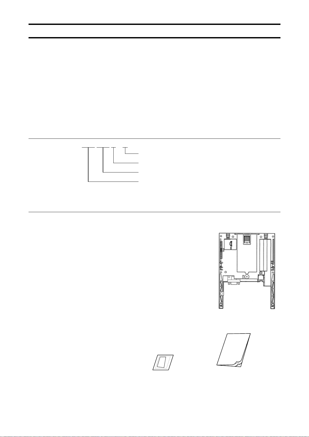
■ Explanation of model number of PROFIBUS option
PDP 002 Z -0
Revision No.
Cable length (cable between inverter and unit), Z: No cable
E6581279⑤
PROFIBUS DP
PROFIBUS option", so please
■Check of accessories
PROFIBUS option is shipped together with the following items in the package. Contact your
sales agency if any of these is missing.
• VF-AS1/PS1 PROFIBUS
(PDP002Z)
• Instruction manual for the VF-AS1/PS1 PROFIBUS
(E6581279)
PROFIBUS model number
PROFIBUS
option ....... 1 board
option (this manual) ....... 1 copy
Manual
LED name label ....... 1 pcs.
•
- 4 -
Page 6

E6581279⑤
Contents
1. OVERVIEW ..............................................................................................................................................6
2. EXTERIOR FEATURES...........................................................................................................................7
2.1. PROFIBUS connector .....................................................................................................................8
2.2. Status indicator ...............................................................................................................................8
3. INSTALLING THE PDP002Z....................................................................................................................9
4. CONNECTING TO THE NETWORK .....................................................................................................10
4.1. Installation method ........................................................................................................................10
4.2. Setting a station address ..............................................................................................................11
5. COMMUNICATIONS-RELATED PARAMETERS..................................................................................13
5.1. f851: Communication Loss Action Setting (Network breaks)..................................................14
5.2. f852: Preset speed operation selection...................................................................................14
5.3. f830: PPO TYPE Setting .........................................................................................................15
6. PROFIBUS LOCAL/REMOTE OPERATION .........................................................................................16
7. SPECIFICATIONS .................................................................................................................................17
8. WARRANTY...........................................................................................................................................17
- 5 -
Page 7

1. Overview
The PDP002Z option allows the VF-AS1/PS1 inverter to be connected as a slave (DP-V0)
into a PROFIBUS network. Up to 126 stations* can be connected to the network (* including
a master. If no repeater is provided, up to 32 stations can be connected to each segment).
Master
(PLC, etc.)
VF-AS1/PS1 VF-AS1/PS1
PDP002Z PDP002Z
PROFIBUS
Maximum connectable units: 126
(In a case like the one above, PLC is
included in the count.)
E6581279⑤
Repeater
VF-AS1/PS1
PDP002Z
- 6 -
Page 8

2. Exterior features
The external view of this option and the name of each part are shown below.
Status indicator
(Refer to Section 2.2)
E6581279⑤
Panel mounting tabs
(Refer to Section 3)
Address switch
(Refer to Section 4.2)
PROFIBUS connector
(Refer to Section 2.1)
Danger
▼ Do not change the switch setting when the power is on.
Prohibited
It could lead to electric shocks, or the option might breaks down or get
damaged.
- 7 -
Page 9

2.1. PROFIBUS connector
Used to connect PROFIBUS network cables. The connector is a D-Sub connector with 9 pin
female and the connector pin allocation described below follows the PROFIBUS standard.
E6581279⑤
9 8 7 6
1 5 4 3 2
The PDP002Z has no termination resistor. Therefore, termination resistors need to be
connected to the station on each side of the PROFIBUS network or the master, as shown in
the figure below. (The PROFIBUS connector with termination resistor are recommended.)
VP(6 pin)
RxD/TxD-P(3 pin)
Pin number Symbol
1 NC Reserved
2 NC Reserved
3 RxD/TxD-P Send/receive data (+)
4 CNTR-P Control signal
5 DGND 0V (Insulated from the inside)
6 VP +5V power
7 NC Reserved
8 RxD/TxD-N Send/receive data (-)
9 NC Reserved
Signal type
390 ohm*
220 ohm
*
RxD/TxD-N(8 pin)
DGND(5 pin)
2.2. Status indicator
The PDP002Z has two LEDs, ST (status) and DX (data exchange) to indicate the
statuses of PROFIBUS-DP and the PDP002Z itself.
ST (Status): Red LED
LED Meanings
Off No diagnostics present
Flashes Waiting for parameterisation or configuration
Lights
DX (Data exchange): Green LED.
390 ohm
*
* 1/4W or more is recommended.
DP status error
* For example, a station address is not set correctly.
Indicates the status of the PROFIBUS network.
It lights when the PDP002Z is on-line and data exchange is possible.
- 8 -
Page 10

3. Installing the PDP002Z
Install the PROFIBUS option to VF-AS1/PS1 as follows:
* When this option is used together with the IO card option, attach this option to the front
panel side.
(1) Turn off input power of VF-AS1/PS1 and wait for at least 15 minutes and then check
that the CHARGE lamp on VF-AS1/PS1 is no longer lit.
(2) Securing the option to the inverter
a) Insert a flat-blade screwdriver in each of the two holes at the upper part of the front
b) Install the
c) Make sure the option is securely attached to the inverter. Then, check whether the
d) Insert the tabs at the lower part of the front cover into the slots at the lower part of
e) Stuck the enclosed "LED name label" on the option LED display part of a front
cover.
panel, release the panel mounting tab by pushing the screwdriver down, and
remove the front panel cover.
option in the inverter by fitting the tabs on the lower side of the option into
the slots at the lower part of the inverter front panel.
plastic bosses on the inverter case have fitted in the holes at the upper and lower
parts of the
option.
the inverter to attach the front cover to the inverter.
a)
E6581279⑤
* When installing this option to below capacities,
remove the Add-on type option case.
VFAS1: 200V 55, 75kW
400V 90 - 500kW
VFPS1: 200V 55 - 90kW
400V 90 - 630kW
b)
e)
LED name label
ST
DX
MNS
MNS
MNS
c)
d)
- 9 -
Page 11

4. Connecting to the network
4.1. Installation method
(1) Using the DIP switchon the PROFIBUS option, seta station address. (Refer to Section
4.2.)
(2) Connect a PROFIBUS connector to the PDP002Z. (Refer to Section 2.1.)
* If the PDP002Z is located at an end of the bus, connect a terminal resistor to it.
E6581279⑤
(When using a connector with
(3) Once all the parameters are set, the power must be cycled to the VF-AS1/PS1 for
these changes to take effect. (Refer to Section 5.)
termination resistor, set it ON.)
- 10 -
Page 12

4.2. Setting a station address
The DIP switch on the circuit board of the option is used to set a station address. Each
DIP switch is ON when it is flipped to the lower position. By default, it is
factory-configured to 2.
The station address must be unique and not match any other device on the network.
1 2 3 4 5 6 7 8
1 2 3 4 5 6 7 8
ID
DIP ON
SW
OFF OFF OFF OFF OFF OFF OFF OFF
0
OFF OFF OFF OFF OFF OFF OFF ON
1
OFF OFF OFF OFF OFF OFF ON OFF
2
OFF OFF OFF OFF OFF OFF ON ON
3
OFF OFF OFF OFF OFF ON OFF OFF
4
OFF OFF OFF OFF OFF ON OFF ON
5
OFF OFF OFF OFF OFF ON ON OFF
6
OFF OFF OFF OFF OFF ON ON ON
7
OFF OFF OFF OFF ON OFF OFF OFF
8
OFF OFF OFF OFF ON OFF OFF ON
9
OFF OFF OFF OFF ON OFF ON OFF
10
OFF OFF OFF OFF ON OFF ON ON
11
OFF OFF OFF OFF ON ON OFF OFF
12
OFF OFF OFF OFF ON ON OFF ON
13
OFF OFF OFF OFF ON ON ON OFF
14
OFF OFF OFF OFF ON ON ON ON
15
OFF OFF OFF ON OFF OFF OFF OFF
16
OFF OFF OFF ON OFF OFF OFF ON
17
OFF OFF OFF ON OFF OFF ON OFF
18
OFF OFF OFF ON OFF OFF ON ON
19
OFF OFF OFF ON OFF ON OFF OFF
20
OFF OFF OFF ON OFF ON OFF ON
21
OFF OFF OFF ON OFF ON ON OFF
22
OFF OFF OFF ON OFF ON ON ON
23
OFF OFF OFF ON ON OFF OFF OFF
24
OFF OFF OFF ON ON OFF OFF ON
25
OFF OFF OFF ON ON OFF ON OFF
26
OFF OFF OFF ON ON OFF ON ON
27
OFF OFF OFF ON ON ON OFF OFF
28
OFF OFF OFF ON ON ON OFF ON
29
OFF OFF OFF ON ON ON ON OFF
30
OFF OFF OFF ON ON ON ON ON
31
SW
ID
32
33
34
35
36
37
38
39
40
41
42
43
44
45
46
47
48
49
50
51
52
53
54
55
56
57
58
59
60
61
62
63
E6581279⑤
1 2 3 4 5 6 7 8
OFF OFF ON OFF OFF OFF OFF OFF
OFF OFF ON OFF OFF OFF OFF ON
OFF OFF ON OFF OFF OFF ON OFF
OFF OFF ON OFF OFF OFF ON ON
OFF OFF ON OFF OFF ON OFF OFF
OFF OFF ON OFF OFF ON OFF ON
OFF OFF ON OFF OFF ON ON OFF
OFF OFF ON OFF OFF ON ON ON
OFF OFF ON OFF ON OFF OFF OFF
OFF OFF ON OFF ON OFF OFF ON
OFF OFF ON OFF ON OFF ON OFF
OFF OFF ON OFF ON OFF ON ON
OFF OFF ON OFF ON ON OFF OFF
OFF OFF ON OFF ON ON OFF ON
OFF OFF ON OFF ON ON ON OFF
OFF OFF ON OFF ON ON ON ON
OFF OFF ON ON OFF OFF OFF OFF
OFF OFF ON ON OFF OFF OFF ON
OFF OFF ON ON OFF OFF ON OFF
OFF OFF ON ON OFF OFF ON ON
OFF OFF ON ON OFF ON OFF OFF
OFF OFF ON ON OFF ON OFF ON
OFF OFF ON ON OFF ON ON OFF
OFF OFF ON ON OFF ON ON ON
OFF OFF ON ON ON OFF OFF OFF
OFF OFF ON ON ON OFF OFF ON
OFF OFF ON ON ON OFF ON OFF
OFF OFF ON ON ON OFF ON ON
OFF OFF ON ON ON ON OFF OFF
OFF OFF ON ON ON ON OFF ON
OFF OFF ON ON ON ON ON OFF
OFF OFF ON ON ON ON ON ON
- 11 -
Page 13

ID
SW
1 2 3 4 5 6 7 8
OFF ON OFF OFF OFF OFF OFF OFF
64
OFF ON OFF OFF OFF OFF OFF ON
65
OFF ON OFF OFF OFF OFF ON OFF
66
OFF ON OFF OFF OFF OFF ON ON
67
OFF ON OFF OFF OFF ON OFF OFF
68
OFF ON OFF OFF OFF ON OFF ON
69
OFF ON OFF OFF OFF ON ON OFF
70
OFF ON OFF OFF OFF ON ON ON
71
OFF ON OFF OFF ON OFF OFF OFF
72
OFF ON OFF OFF ON OFF OFF ON
73
OFF ON OFF OFF ON OFF ON OFF
74
OFF ON OFF OFF ON OFF ON ON
75
OFF ON OFF OFF ON ON OFF OFF
76
OFF ON OFF OFF ON ON OFF ON
77
OFF ON OFF OFF ON ON ON OFF
78
OFF ON OFF OFF ON ON ON ON
79
OFF ON OFF ON OFF OFF OFF OFF
80
OFF ON OFF ON OFF OFF OFF ON
81
OFF ON OFF ON OFF OFF ON OFF
82
OFF ON OFF ON OFF OFF ON ON
83
OFF ON OFF ON OFF ON OFF OFF
84
OFF ON OFF ON OFF ON OFF ON
85
OFF ON OFF ON OFF ON ON OFF
86
OFF ON OFF ON OFF ON ON ON
87
OFF ON OFF ON ON OFF OFF OFF
88
OFF ON OFF ON ON OFF OFF ON
89
OFF ON OFF ON ON OFF ON OFF
90
OFF ON OFF ON ON OFF ON ON
91
OFF ON OFF ON ON ON OFF OFF
92
OFF ON OFF ON ON ON OFF ON
93
OFF ON OFF ON ON ON ON OFF
94
OFF ON OFF ON ON ON ON ON
95
E6581279⑤
SW
ID
96
97
98
99
100
101
102
103
104
105
106
107
108
109
110
111
112
113
114
115
116
117
118
119
120
121
122
123
124
125
126
1 2 3 4 5 6 7 8
OFF ON ON OFF OFF OFF OFF OFF
OFF ON ON OFF OFF OFF OFF ON
OFF ON ON OFF OFF OFF ON OFF
OFF ON ON OFF OFF OFF ON ON
OFF ON ON OFF OFF ON OFF OFF
OFF ON ON OFF OFF ON OFF ON
OFF ON ON OFF OFF ON ON OFF
OFF ON ON OFF OFF ON ON ON
OFF ON ON OFF ON OFF OFF OFF
OFF ON ON OFF ON OFF OFF ON
OFF ON ON OFF ON OFF ON OFF
OFF ON ON OFF ON OFF ON ON
OFF ON ON OFF ON ON OFF OFF
OFF ON ON OFF ON ON OFF ON
OFF ON ON OFF ON ON ON OFF
OFF ON ON OFF ON ON ON ON
OFF ON ON ON OFF OFF OFF OFF
OFF ON ON ON OFF OFF OFF ON
OFF ON ON ON OFF OFF ON OFF
OFF ON ON ON OFF OFF ON ON
OFF ON ON ON OFF ON OFF OFF
OFF ON ON ON OFF ON OFF ON
OFF ON ON ON OFF ON ON OFF
OFF ON ON ON OFF ON ON ON
OFF ON ON ON ON OFF OFF OFF
OFF ON ON ON ON OFF OFF ON
OFF ON ON ON ON OFF ON OFF
OFF ON ON ON ON OFF ON ON
OFF ON ON ON ON ON OFF OFF
OFF ON ON ON ON ON OFF ON
OFF ON ON ON ON ON ON OFF
- 12 -
Page 14

E6581279⑤
5. Communications-related parameters
On the network, the VF-AS1/PS1 (including the PDP002Z) serves as a slave device. Using
the parameters listed below, set the slave device on the network and its mode of operation.
The GSD files used to configure the PDP002Z can be downloaded from the following web
site.
VF-AS1 http://www.inverter.co.jp/product/inv/vfas1/pdp/
VF-PS1 http://www.inverter.co.jp/product/inv/vfps1/pdp/
Parameter Function Adjustment range Default setting
f830* Communication
option setting 1
(PPO TYPE)
f851 Inverter operation at
the communications
loss action
(Network wire breaks)
f852 Preset speed operation
selection
f853 Monitoring of
communication
device station
address
f854** Monitoring of
communications
device’s baud rate
0: None
1: PPO TYPE 1
2: PPO TYPE 2
3: PPO TYPE 3
4: PPO TYPE 4
0: Stop and break of connection
1: None
2: Deceleration stop
3: Coast stop
4: Emergency stop
5: Preset speed operation command
(Operating at the preset speed operation frequency
set with f852)
0: None
1 to 15: Preset speed
Displays the station address assigned with the
DIP switch.
0 to 125
Displays the network communication speed set
with the DIP switch.
0: 12 Mbit/s
6 Mbit/s
1:
3 Mbit/s
2:
1.5 Mbit/s
3:
500 kbit/s
4:
187.5 kbit/s
5:
93.75 kbit/s
6:
45.45 kbit/s
7:
19.2 kbit/s
8:
9.6 kbit/s
9:
255: Disabled
0
0
0
1
0
* When the parameters are changed, the power must be cycled to the VF-AS1/PS1 for the
changes to take effect.
** The baud rate of the PDP002Z is automatically set by configuration a baud rate for the
master.
- 13 -
Page 15

E6581279⑤
5.1. f851: Communication Loss Action Setting (Network breaks)
This parameter sets up the VF-AS1/PS1 response to a loss of communications with the
PROFIBUS network. (On some occasions, the master side will need to be configured.)
0: Stop and break of connection
The inverter decelerates the motor to a stop and gives the alarm.
Commands entered through the network are canceled, and the commands set with
parameters cmod and fmod become effective.
When communications are restored, the alarm is turned off.
1: None
The inverter remains in the state where it was when the problem arose, and it gives the
alarm.
2: Deceleration stop
The inverter decelerates the motor to a stop and gives the alarm. Commands
entered through the network are not canceled.
3: Coast stop
The inverter issues a command for a frequency of 0Hz and gives the alarm.
Commands entered through the network are not canceled.
4: Emergency stop
The error message err8 is displayed. Commands entered through the network are
not canceled.
When communications are restored, the inverter is not restored to working order and
the error message err8 does not disappear until the inverter is reset.
5: Preset speed operation command
Refer to Section 5.2
5.2. f852: Preset speed operation selection
If the communication loss action (parameter f851) is set to 5 (preset speed command),
the VF-AS1/PS1 will run at a preset speed as set up by this parameter in the case of a
communication loss (with alarm). Commands entered through the network are not
canceled.
For example,
If the inverter is set as described below,
f851 = 5 (preset speed operation command)
f852 = 8 (preset speed operation frequency 8)
f287 (preset speed operation frequency 8) = 10 (10Hz)
Operation is carried out as follows.
Network Operation of the VF-AS1/PS1
Normal conditions ...........Operates according to commands entered through the network.
↓ ↓
communications loss ......Operates at 10Hz.
↓ ↓
Restoration......................Operates according to commands entered through the network.
- 14 -
Page 16

5.3. f830: PPO TYPE Setting
The PPO type of PDP002Z is set up by this parameter.
The PROFIBUS-DP protocol uses so-called PPOs (Parameter/Process Data Objects) in
cyclic communication. The figures below show the PPO types and configurations that the
E6581279⑤
PDP002Z supports
.
PKW PZD
PZD1
PKE IND PWE
PPO TYPE 1: Octet-String 12
PPO TYPE 2: Octet-String 20
PPO TYPE 3: Octet-String 4
PPO TYPE 4: Octet-String 12
STW
ZSW
PZD2
HSW
HIW
PZD3 PZD4 PZD5 PZD6
PKW: Parameter ID/value
PZD: Process Data, cyclically transferred
PKE: Parameter ID (1st and 2nd octet)
IND: Sub-index (3rd octet), 4th octet is reserved
PWE: Parameter value (5th until 8th octet)
STW: Control word
HSW: Main setpoint
ZSW: Status word
HIW: Main actual value
- 15 -
Page 17

6. PROFIBUS Local/Remote Operation
t
The example below shows how to configure the VF-AS1/PS1 for local / remote operation.
<Terminal function>
F terminal ............ RUN command
R terminal............ PROFIBUS/Local (Terminal in this example) switching
RR/S4 terminal.... Operation frequency command
<Wiring>
Variable resistor for adjustmen
10k ohm
Operation command
E6581279⑤
VF-AS1/PS1
PP
RR/S4
CCA
SW1
F
PROFIBUS/Local
Switch
R
CC
<Parameter setting>
cmod (command mode selection) = 0 (terminal board)
fmod (frequency setting mode selection 1) = 2 (RR/S4)
f112 (input terminal selection 2 (R)) = 48 (PROFIBUS/Local control)
<Operation>
R-CC terminal open:
VF-AS1/PS1 is controlled as slave device of PROFIBUS.
R-CC terminal closed:
F-CC terminal short to RUN
F-CC terminal open to STOP
Output frequency is set up by the RR/S4 signal input.
SOURCE
SINK
- 16 -
Page 18

7. Specifications
Item Specifications
Model number PDP002Z
PROFIBUS DP-V0
PPO TYPE: 1 to 4 by No.3.072 Profile for Variable Speed Drives
Technical data
Use environments
Ambient
temperature
Storage
temperature
Relative humidity 20 to 93% (no condensation and absence of vapor)
Vibration 5.9m/s2 {0.6G} or less (10 - 55Hz)
Connector: D-Sub 9 pin female
Station address setting: DIP switch
Baud rate: 9.6 kbps up to 12Mbps
Indoors, an altitude of 3,000m or less, where the product will not be exposed to direct
sunlight, corrosive or explosive gases, vapor, coarse particulates including dust, and
where there is no grinding fluid or grinding oil nearby
-10 to +60°C
-25 to +65°C
E6581279⑤
8. Warranty
Any part of the inverter that proves defective will be repaired free of charge under the following
conditions:
1. If and when a trouble occurs on the option unit properly installed and handled within one
2. This warranty applies only to the option unit.
3. For the following kinds of failure or damage, the repair cost shall be borne by the customer
4. If terms and conditions of warranty are otherwise specified, priority is given to them.
year of delivery, and if the trouble is clearly attributable to defects inherent in our design and
manufacture, the product will be repaired free of charge.
even within the warranty period.
1) Failure or damage caused by improper or incorrect use or handling, or unauthorized
repair or modification of the option.
2) Failure or damage caused by the option falling or an accident during transportation after
the purchase.
3) Failure or damage caused by fire, salty water or wind, corrosive gas, earthquake, storm
or flood, lightning, abnormal voltage supply, or other natural disasters.
4) Damage sustained as a result of the fact that the product was used for any application
other than that designated for the PROFIBUS option (circuit board) for the VF-AS1
/PS1.
- 17E -
- 17 -
 Loading...