

Page 1

FILE NO : A06-009
Quick reference
R410A
Page 2
Refrigerant Piping
01
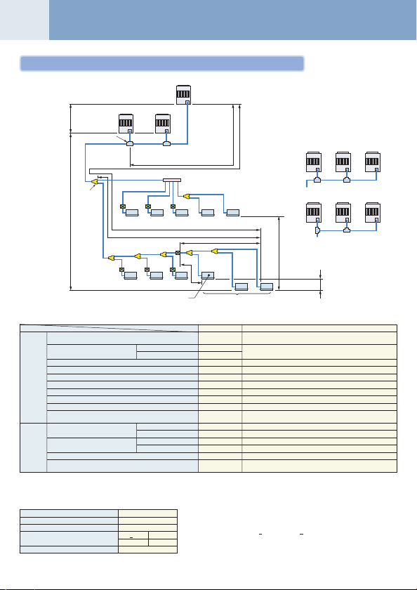
Allowable length of refrigerant pipe and height difference
Follower unit C
Follower unit B
Height difference
between
outdoor units
H3 £ 5 m
Height difference
between outdoor
and indoor units
H1 £ 50 m
•Allowable length/height difference of the refrigerant pipe
Total extension of pipe (Liquid pipe/real length)
Farthest piping length L (*1)
Max. equivalent length of main piping
Equivalent length of farthest piping from 1 st branching Li (*1)
Pipe
Max. real length of indoor unit connecting piping
length
Max. real length between FS unit and indoor unit (*2)
Max. equivalent length of outdoor unit connecting pipe LO (*1)
Max. real length of outdoor unit connecting pipe
Max. equivalent length between FS unit and indoor unit Lj
Max. real length between FS unit and indoor unit which FS unit
control wiring is connected Lh (*2)
Height between
indoor unit and outdoor unit H1
Height between
Height
indoor unit H2
difference
Height between outdoor units H3
Height difference between indoor units in group control by one
FS unit H4
*1 : The farthest indoor unit from 1st branch to be named C, and fa rthest indoor unit from 1st branch to be named (q).
*2 : Attached connection cable can be used up to 5 m in pipe length between indoor unit and FS unit.
When the pipe length between indoor and FS unit exceeds 5 m, be sure to use the connection cable kit (RBC-CBK15FE).
• Restriction to the system
Max. No. of combined outdoor units
Max. capacity of combined outdoor units
Max. No. of connected indoor units
Max. capacity of connected indoor units
Min. capacity of connected indoor units
*3 : MMY-MAP1202FT8 up to 120%.
Header unit A
Outdoor unit
T-Shape branching
main piping
L1
Branching piping L2
Connecting piping of
1st
indoor unit
branching
section
L3
Indoor unit
Equivalent length corresponded to farthest piping L £ 150 m
Equivalent length corresponded to farthest piping after 1st branching Li £ 50 m
L4
d
FS unit
l
Indoor unit
Indoor unit which FS unit control wiring is connected.
H2 < 15 m 135% (*3)
H2 > 15 m 105%
Outdoor capacity : 70%
Lb Lc
La
LA
Main connecting piping between outdoor units
Length corresponded to farthest piping
between outdoor units LO £ 25 m
bca
hi jkg
L6 L7
L5
f
e
n
m
Real length
Equivalent length
Upper outdoor unit
Lower outdoor unit
Upper outdoor unit
Lower outdoor unit
3 units
84.0 kW
48 units
Branching header
L9
FS unit
<Cooling only> <Cooling only>
L8
FS unit
o
Lh
When connecting the plural indoor units to single FS unit.
Allowable value
Note 1) Combination of outdoor unit : Header unit (1 unit) + Follow unit
Note 2) Install the outdoor units in order of capacity.
Note 3) Refer to outdoor unit combination table in page 5.
Note 4) Piping to indoor units shall be per pendicular to piping to the
•Cautions concerned with installation/construction
1) The leading outdoor unit connected with the indoor
inter-unit pipe is made “A (Header unit)”.
2) Set the units in order of the outdoor capacity.
(A (Header unit) > B > C > D)
3) For the combination of the outdoor units, refer to
“Combination of outdoor unit” list.
Note:
In case of connecting method <Ex.2>, a large amount of
refrigerant and refrigerant oil may return to the head unit.
Therefore, set the T-shape joint so that oil does not enter directly.
Lj
p
q
<Group control>
LA + La + Lb + Lc + L1 + L2 + L3 + L4 + L5 + L6 + L7 + L8 + L9
300 m
+ a + b + c + d + e + f + g + h + i + j + k + l + m + n + o+ p + q
125 m
150 m
85 m
50 m
30 m
15 m
25 m
10 m
30 m
15 m
50 m
30 m
35 m
15 m
5 m
0.5 m
(0 to 2 units). Header unit is outdoor unit nearest to the connected indoor units.
Header
<Ex.1>
unit A
OK
Header
<Ex.2>
unit A
NO GOOD
Height difference between
indoor units H2 £ 35
(Upper outdoor unit)
Height difference between
indoor units in group control
by one FS unit H4 £ 0.5 m
Pipe section
LA + Lc + L1 + L3 + L4 + L5 + L6 + L7 + L8 + q
a + g, b + h, c + i, d + l, e + m, f + m, f + n, j, k
L1
L3 + L4 + L5 + L6 + L7 + L8 + q
g, h, i, l, m, n, L7 + o
LA + Lc (LA + Lb)
La, Lb, Lc
L7 + L8 + p, L7 + L8 + q
L7 + o
——
——
——
——
——
——
(Header unit > Follow unit 1 > Follow unit 2)
head outdoor unit as <Ex. 1>. Do not connect piping to indoor
units in the same direction of head outdoor unit as <Ex. 2>.
Follower
unit B
Follower
unit B
Follower
unit C
Follower
unit C
Page 3
02
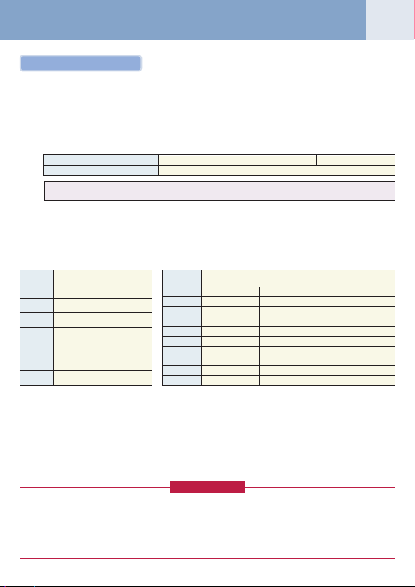
Addition of refrigerant
After vacuuming work, exchange the vacuum pump with the refrigerant bomb and then start the additional charging work
of refrigerant.
Calculation of additional refrigerant charge amount
Refrigerant charge amount at shipment from the factory does not include the refrigerant for pipe at the local site.
For refrigerant to be charged in pipe at the local site, calculate the amount and charge it additionally.
Note) If the additional refrigerant amount indicates minus as the result of calculation, use the air conditioner without
addition of refrigerant.
Outdoor unit Model
Charging amount (kg)
Additional refrigerant
charge amount at local site
Example : Additional charge amount R (kg) = {(L1 × 0.025kg/m) + (L2 × 0.055kg/m) + (L3 × 0.105kg/m)} × 1.3
Table-1 Table-2
Liquid
pipe dia.
Charging of refrigerant
•Keeping valve of the outdoor unit closed, be sure to charge the liquid refrigerant into service port at liquid side.
• If the specified amount of refrigerant cannot be charged, open fully valves of outdoor unit at liquid and discharge/
suction gas sides, balance side operate the air conditioner in COOL mode under condition that valve at suction gas
side is a little returned to close side, and then charge refrigerant into service port at suction gas side. In this time,
choke the refrigerant slightly by operating valve of the bomb to charge liquid refrigerant.
The liquid refrigerant may be charged suddenly, therefore be sure to charge refrigerant gradually.
•When refrigerant leaks and refrigerant shortage occurs in the system, recover the refrigerant in the system and recharge refrigerant newly up to the correct level.
<Entry of refrigerant charge amount>
•Fill the additional refrigerant record column of the wiring diagram indication plate with the additional refrigerant
• The total refrigerant amount means the total value of the refrigerant amount at shipment and the additional refriger-
Additional refrigerant
amount/1m liquid pipe (kg/m)
(mm)
6.4
9.5
12.7
15.9
19.1
22.2
amount at installation work, total refrigerant amount and the name of the service man who charged refrigerant at
installation time.
0.025
0.055
0.105
0.160
0.250
0.350
ant amount at installation time. The refrigerant amount at the shipment is one described on the “Unit nameplate”.
MMY-MAP0802FT8 MMY-MAP1002FT8 MMY-MAP1202FT8
Real length
=× ×
( )
of liquid pipe
Additional refrigerant charge
amount per 1m liquid pipe (Table 1)
L1 : Real total length of liquid pipe Ø6.4 (m)
L2 : Real total length of liquid pipe Ø9.5 (m)
L3 : Real total length of liquid pipe Ø12.7 (m)
System : 10HP
Combined
(HP)
8
10
12
16
18
20
24
26
28
30
Combined outdoor unit
8
10
12
8 8
10 8
10 10
8 8 8
10 8 8
10 10 8
10 10 10
(HP)
11.5
Compensation by
1.3
system HP (Table 2)
C (Corrected refrigerant amount)
–1.5
–4.5
–3.0
–1.5
(kg)
2.0
2.5
3.0
0.0
2.0
0.0
REQUIREMENT
Page 4

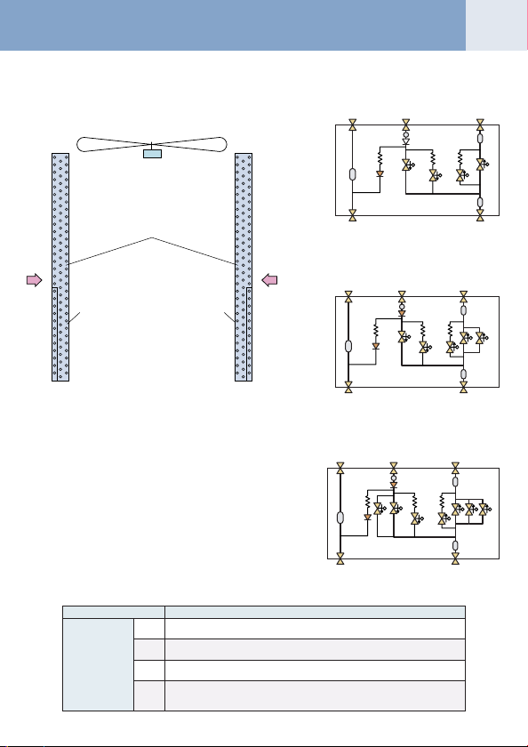
Refrigerant Piping Diagram (Outdoor)
03
Inverter unit (8, 10, 12HP)
Model: MMY-MAP0802FT8, MAP1002FT8, MAP1202FT8
Propeller fan
Fan motor
FM
(Right side)
Main heat exchanger
(Left side)
Main heat exchanger
Sub heat exchanger (Right side)
Sub heat exchanger (Left side)
Solenoid valve (SV11)
Check valve
Solenoid valve
Oil
separator
Strainer
Check valve Check valve
tube
Sensor
(TK3)
Strainer
Check
valve
Sensor
(TK1)
(SV3A)
Check valve
Strainer
Solenoid valve
(SV3C)
Strainer
Check
valve
Capillary tube
Sensor
(TK2)
Oil tank
Solenoid valve
(SV3B)
Check valve
Compressor 2
Capillary
Sensor (TK4)
Solenoid valve
(SV2)
(Inverter)
4-Way valve
Capillary
tube
Capillary tube
Solenoid valve
(SV42)
High-pressure
switch
Sensor
(TD2)
Sensor
(TO)
Pulse motor valve
Solenoid valve
(PMV1) (PMV2)
Check valve
Strainer
Sensor
(TL)
Liquid
tank
Check
joint
Strainer Strainer
Service valve
Service valve at
of balance pipe
discharge gas side
Service valve
Service valve at
at liquid side
suction gas side
Sensor
(TE1)
Strainer
(SV12)
Strainer
(PMV3)
Check valve
Solenoid valve
(SV5)
Capillary
High-pressure
tube
Solenoid valve
(SV6)
Solenoid valve
Solenoid valve
sensor
Check joint
Capillary tube
Strainer
(SV3D)
Capillary tube
(SV41)
High-pressure
switch
Sensor
(TD1)
Compressor 1
(Inverter)
Capillary tube
Solenoid valve
(SV3E)
Capillary tube Capillary tube
Strainer
Sensor
(TS1)
Sensor
(TS2)
Low-pressure
Accumulator
sensor
Check
joint
Page 5
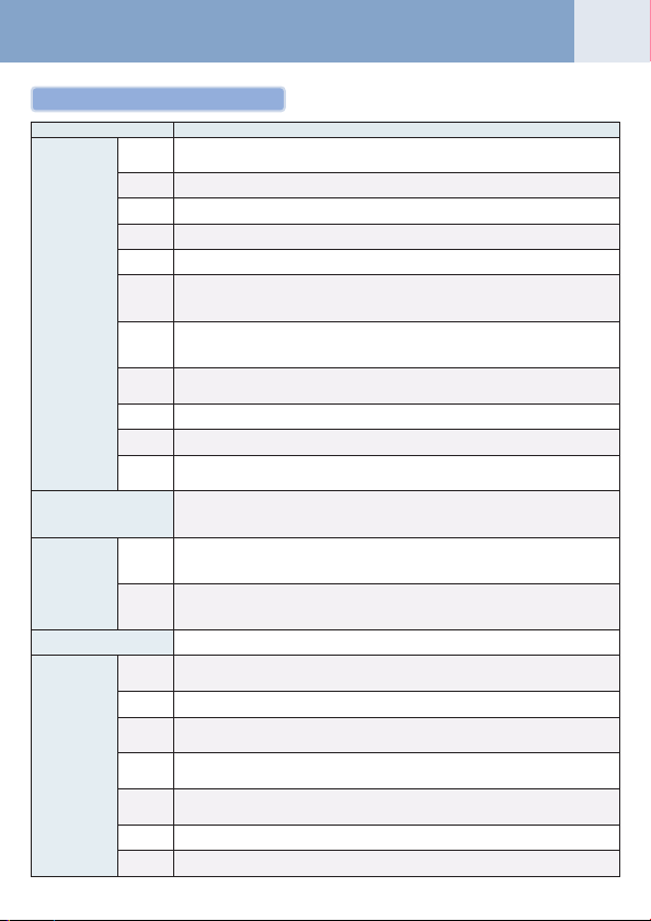
Explanation of functional parts
Functional part name
Solenoid valve
4-way valve
Pulse motor valve
Oil separator
Temp. sensor
(Connector CN324: Red)
SV3A
Closed : Allows oil to collect/remain in the oil tank.
Open : Allows oil to exit the oil tank.
(Connector CN313: Blue)
SV3B
Open : Allows oil to return to the outdoor unit via the balance pipe.
(Connector CN314: Black)
SV3C
Open : Pressurizes the oil tank.
(Connector CN323: White)
SV3D
Open : Supplies oil to the compressor from the oil separator.
(Connector CN323: White)
SV3E
Open : Tu rns on during operation and balances oil between compressors.
(Hot gas bypass) (Connector CN312: White)
1) Low pressure release function
ASV2
2) High pressure release function
3) Gas balance function during stop time
(Gas balance control for compressor start-up) (Connector CN311: Blue)
SV41
1) For gas balance start
SV42
2) High pressure release function
3) Low pressure release function
(Connector CN310: White)
SV5
1) Increase of No. of heating indoor units, Gas balance function in defrost time
2) Low-pressure balance function of discharge gas pipe during all cooling operation
(Connector CN309: White)
SV6
1) Liquid bypass function for discharge temp. release (Cooling bypass circuit)
(Connector CN322: White)
SV11
1) For shutdown discharge gas (During all cooling operation and defrost operation)
(Connector CN319: White)
SV12
1) Flow-rate control function of refrigerant to sub heat exchanger during simultaneous operation
2) Flow-rate control function of refrigerant to sub heat exchanger during defrost operation
(Connector CN317: Blue)
1) Cooling/Heating selection
2) Reverse defrost
3) Main-/Sub-heat exchanger selection
(Connector CN300, 301: White)
1) Super heat control function during all heating operation and mainly heating, partly cooling operation
PMV1, 2
2) Under-cool adjustment function during all cooling operation
3) Divided flow control function during mainly cooling, partly heating operation
(Connector CN302: Red)
1) For flow-rate control of sub heat exchanger during simultaneous operation
PMV3
TD1, TD2
TS1
TS2
TE
TK1, TK2,
TK3, TK4
TL
TO
(Control function of heating divided flow)
2) A function preventive high pressure up during all cooling or all heating operation
1) Prevention for early drop of oil level (Decrease of flow-out of discharge oil to cycle)
2) Reser ve function of surplus oil
(TD1: Connector CN502: White, TD2: Connector CN503: Pink)
1) Protection of compressor discharge temp.
2) Releasing of discharge temp.
(Connector CN504: White)
1) Controls super heat of PMV1 and 2 during all heating operation and simultaneous operation
(Connector CN522: Black)
1) Controls indoor oil recovery during all cooling operation and mainly cooling, partly heating operation
2) Detects overheat of cycle.
(Connector CN505: Green)
1) Controls defrost during all heating operation and simultaneous operation.
2) Controls outdoor fan during all heating operation and simultaneous operation.
TK1: Connector CN514: Black, TK2: Connector CN515: Green,
æ ö
è ø
TK3: Connector CN516: Red, TK4: Connector CN523: Yellow
1) Judges oil level of compressor.
(Connector CN521: White)
1) Detects under-cool during all cooling operation and simultaneous operation.
(Connector CN507: Ye llow)
1) Detects external ambient temperature.
04
Functional outline
Page 6
Continued
05
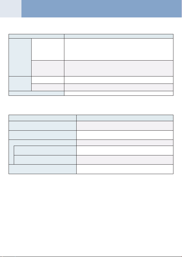
Functional part name
High pressure sensor
Pressure sensor
Low pressure sensor
Heater
Balance pipe
Compressor case heater
Accumulator case heater
<Operation mode>
Operation mode
1. All Indoor Unit(s) Operating for Cooling
2. All Indoor Unit(s) Operating fo r Heating
3. Simu ltaneous operation
3-1. Mainly cooling, par tly heating operation
3-2. Mainly heating, par tly cooling operation
4. Defrost
(Connector CN501: Red)
1) Detects high pressure and uses it to control capacity of compressor.
2) Detects high pressure during all cooling operation and uses it to control fan when
cooling with low outside air.
3) Detects under-cool of the indoor unit of which heating thermo.-ON during all heating
operation and simultaneous operation.
4) Controls outdoor fan rpm during mainly cooling, par t heating operation.
(Connector CN500: White)
1) Detects low pressure and uses it to control capacity of compressor during all cooling
operation and simultaneous operation
2) Detects low pressure and uses it to controls super heat during all heating operation
and simultaneous operation
(Compressor 1 Connector CN316: White, Compressor 2 Connector CN315: Blue)
1) Prevents liquid accumulation in the compressor
(Connector CN321: Red)
1) Prevents liquid accumulation to accumulator
1) Oil balancing pipe between outdoor unit (This unit does not use this Balance pipe.)
Only cooling operation without heating operation
Outdoor heat exchanger (Main heat exchanger) is used as condenser.
Only heating operation without cooling operation
Outdoor heat exchanger (Main heat exchanger) is used as evaporator.
MIU for simultaneous operation
Cooling/heating simultaneous operation with subjective cooling operation
Outdoor heat exchanger (Sub heat exchanger) is used as condenser.
Cooling/heating simultaneous operation with subjective heating operation
Outdoor heat exchanger (Main heat exchanger) is used as evaporator.
Using reversing operation of 4-way valve, ice of the outdoor heat
exchanger is dissolved with single cooling cycle.
Functional outline
Outline
Page 7
Configuration of outdoor unit heat exchanger Flow Selector Unit (FS Unit)
* RBM-Y1801FE has two “SVS” valves.
Check
valve
Strainer
SVS
SVSS
SVDD
SVD
Liquid pipe
Strainer
Discharge gas pipe Suction gas pipe
To indoor
gas side
To indoor
liquid side
Strainer
Capillary
tube
Capillary
tube
Capillary
tube
Check
valve
Strainer
SVS SVS
SVSS
SVDD
SVD
Liquid pipe
Strainer
Discharge gas pipe Suction gas pipe
To indoor
gas side
To indoor
liquid side
Strainer
Capillary
tube
Capillary
tube
Capillary
tube
* RBM-Y2802FE has three “SVS” valves and two “SVD”.
Check
valve
Strainer
SVS SVS
SVSS
SVDD
SVD
Liquid pipe
Strainer
Discharge gas pipe Suction gas pipe
To indoor
gas side
To indoor
liquid side
Strainer
Capillary
tube
Capillary
tube
Capillary
tube
SVS
RBM-Y1122FE
Propeller fan
Fan motor
Main heat exchanger
RBM-Y1802FE
Wind
Sub heat
exchanger
Front side
(Right)
Sub heat
exchanger
Rear side
(Left)
Wind
RBM-Y2802FE
06
Functional part name
Solenoid valve
(Discharge gas block valve)
SVD
1) High pressure gas circuit during heating operation
(Suction gas block valve)
SVS
1) Low pressure gas circuit during cooling operation
(Pressure valve)
SVDD
1) For pressurizing when No. of heating indoor units increases.
(Reducing valve)
SVSS
1) For recovery of refrigerant of the stopped indoor unit of which cooling thermo-OFF
2) For reducing pressure when No. of heating indoor units decreases.
Functional outline
Page 8
System Refrigerant Cycle Drawing
07
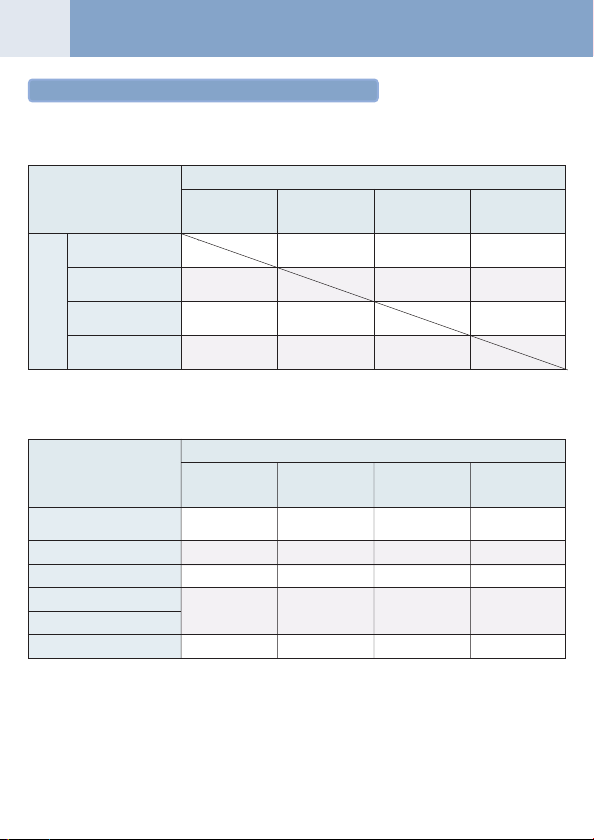
Refrigerant piping systematic diagram in system
<Selection of operation mode>
For the selection of each operation mode, see the table below:
“Stop Once” means the system does not operate for 3 minutes after operation before update has stopped.
After update
All cooling operation Mainly cooling, partly Mainly heating, partlyAll heating operation
(OFF) (ON) (ON) (ON)
All cooling operation
(OFF)
Mainly cooling, partly
heating cooperation (ON)
Before
update
Mainly heating, partly
cooling operation (ON)
All heating operation
(ON)
Note) Phrases in parentheses in the table indicate status of 4-way valve.
Operation continues Operation continues Operation continues
(ON ® OFF) (As ON) (As ON)
Stop Once Operation continues Operation continues
(ON ® OFF) (As ON) (As ON)
Stop Once Operation continues Operation continues
(ON ® OFF) (As ON) (As ON)
<ON-OFF list of Flow Selector Unit (FS Unit) valve>
Indoor operation mode
1. Stop (Remote controller OFF)
<All system stop>
2. Cooling ther mo-OFF
3. Cooling ther mo-ON
4. Heating ther mo-OFF
5. Heating ther mo-ON
6. “E04” error is being detected
SVD SVDD SVS SVSS
(High pressure(Pressure valve (Low pressure (Reducing valve
circuit valve) <For delay>) circuit valve) <For delay>)
OFF OFF OFF ON
<OFF> <OFF> <OFF> <OFF>
OFF OFF OFF ON
OFF OFF ON ON
ON OFF OFF OFF
OFF ON OFF OFF
heating cooperation cooling operation
Operation continues Operation continues Stop once
(OFF ® ON) (OFF ® ON) (OFF ® ON)
Outline of control valve output of FS unit (Basic operation)
Page 9

Check Code List
08
Main
remote
controller
display
Communication error between indoor and remote controller
E01
(Detected at remote controller side)
E02
Sending error of remote controller
Communication error between indoor and remote controller
E03
(Detected at indoor side)
Communication circuit error between indoor and outdoor
E04
(Detected at indoor side)
E06
Decrease of No. of indoor units
Communication circuit error of indoor and outdoor
E07
(Detected at outdoor side)
E08
Duplicated indoor addresses
E09
Duplicated master remote controllers
E10
Communication error in indoor P. C. B ass’y
E12
Automatic address start error
E15
No indoor automatic address
E16
No. of connected indoor units / Capacity over
E18
Communication error between indoor header and follower units
E19
Outdoor header units quantity error
E20
Other line connected during automatic address
E23
Sending error in communication between outdoor units
E25
Duplicated follower outdoor addresses
E26
Decrease of No. of connected outdoor units
E28
Follower outdoor error
E31
IPDU communication error
F01
Indoor TCJ sensor error
F02
Indoor TC2 sensor error
F03
Indoor TC1 sensor error
F04
TD1 sensor error
F05
TD2 sensor error
F06
TE1 sensor error
F07
TL sensor error
F08
TO sensor error
F10
Indoor TA sensor error
F12
TS1, TS2 sensor error
F13
TH sensor error
F15
Outdoor temp sensor misconnecting (TE, TL)
F16
Outdoor pressure sensor misconnecting (Pd, Ps)
F23
Ps sensor error
F24
Pd sensor error
F29
Indoor other error
F31
Outdoor EEPROM error
H01
Compressor break down
Magnet switch error
H02
Overcurrent relay operation
Compressor error (lock)
H03
Current detect circuit system error
Check code name
Main
remote
controller
display
H04
Comp 1 case thermo operation
H06
Low pressure protective operation
H07
Oil level down detective protection
H08
Oil level detective temp sensor error
H14
Comp 2 case thermo operation
Oil level detective circuit error
H16
Magnet switch error
Overcurrent relay operation
L03
Duplicated indoor header units
L04
Duplicated outdoor line addresses
Duplicated indoor units with priority
L05
(Displayed on indoor unit with priority)
Duplicated indoor units with priority
L06
(Displayed in unit other than indoor unit with priority)
L07
Group line in individual indoor unit
L08
Indoor group/Address unset
L09
Indoor capacity unset
L10
Outdoor capacity unset
L17
Inconsistency error of outdoor units
L18
FS unit error
L20
Duplicated central control addresses
L28
Over No. of connected outdoor units
L29
No. of IPDU error
L30
Auxiliary interlock in indoor unit
L31
IC error
P01
Indoor fan motor error
P03
Discharge temp TD1 error
P04
High-pressure SW detection error
P05
Phase-missing detection / Phase order error
P07
Heat sink overheat error
P10
Indoor overflow error
P12
Indoor fan motor error
P13
Outdoor liquid back detection error
P15
Gas leak detection
P17
Discharge temp TD2 error
P19
4-way valve inverse error
P20
High-pressure protective operation
P22
Outdoor fan IPDU error
P26
G-TR short protection error
P29
Comp position detective circuit system error
P31
Other indoor unit error (Group follower unit error)
—
Error in indoor group
—
AI-NET communication system error
—
Duplicated network adaptors
Check code name
Page 10
Address Setup
09
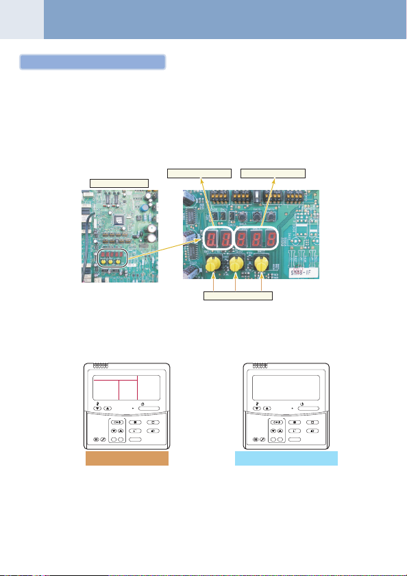
Pre-check for address setup
<Check on outdoor unit>
1. Check that all the rotary switches, SW01, SW02, and SW03 on the interface P. C. board of the outdoor unit are set up
to “1”.
2. If other error code is displayed on 7-segment [B], remove the cause of trouble referring to “9. Troubleshooting”.
3. Check that [L08] is displayed on 7-segment display [B] on the interface P. C. board of the outdoor unit.
(L08: Indoor address unset up)
(If the address setup operation has already finished in service time, etc, the above check code is not displayed, and
only [U1] is displayed on 7-segment display [A].)
Interface P. C. board
7-segment display [A] 7-segment display [B]
SW01 SW02 SW03
<Check on indoor unit>
1. Display check on remote controller (In case of wired remote controller)
Check that a frame as shown in the following left figure is displayed on LC display section of the remote controller.
GOOD
TEMP.
FILTER
TEST
RESET
(Power and operation stop)
If a frame is not displayed as shown in the above right figure, the power of the remote controller is not normally turned
on. Therefore check the following items.
• Check power supply of indoor unit.
• Check wiring between indoor unit and remote controller.
• Check whether there is cutoff of cable around the indoor control P. C. board or not, and check connection failure of
connectors.
• Check failure of transformer for the indoor microcomputer.
FAN
TIMER SET
SWING/FIXTIME
UNITSET CL
Normal status
ON / OFF
MODE
VENT
NO
GOOD
FILTER
RESET
(Power is not normally turned on.)
TEMP.
TIMER SET
SWING/FIXTIME
TEST
Abnormal status
ON / OFF
FAN
MODE
VENT
UNITSET CL
Page 11
Automatic Address Setup
Without central control : To the address setup procedure 1
With central control: To the address setup procedure 2
(Example)
Address setup procedure
Cable systematic diagram
(However, go to the procedure 1 when the central control is performed in a single refrigerant line.)
In case of central control in a single refrigerant line
Outdoor
Indoor
Remote
controller
To procedure 1
Central
remote controller
Indoor
Remote
controller
Outdoor
Indoor
Remote
controller
Central
remote controller
Indoor
Remote
controller
In case of central control over refrigerant lines
Outdoor
Indoor
Remote
controller
To procedure 2
Indoor
Remote
controller
Outdoor
Indoor
Remote
controller
Central
remote controller
Indoor
Remote
controller
10
Address setup procedure 1
1. Tu rn on power of indoor/outdoor units.
(In order of indoor
2. After approx. 1 minute, check that U. 1. L08 (U. 1. flash) is displayed in
7-segment display section on the interface P. C. board of the outdoor unit.
3. Push SW15 to start the setup of the automatic addressing.
(Max. 10 minutes for 1 line (Usually, approx. 5 minutes))
4. When the count Auto 1 ® Auto 2 ® Auto 3 is displayed in 7-segment
display section, and it changes from U. 1. - - - (U. 1. flash) to
U. 1. - - - (U. 1. light) , the setup finished.
5. When performing an automatic address setup on a single refrigerant
line with central control, connect relay connected between [U1, U2]
and [U3, U4] terminals in the header unit.
®®
® Outdoor)
®®
REQUIREMENT
•When a group control is performed over the multiple
refrigerant lines, be sure to turn on the power supplies
of all the indoor units connected in a group at the time
of address setup.
• If turning on the power for each refrigerant line to set
up address, a header indoor unit is set for each line.
Therefore, an alarm code “L03” (Duplicated header
indoor units) is output in operation after address setup.
In this case, change the group address from the wired
remote controller for only one header unit is set up.
Header unit interface P. C. board
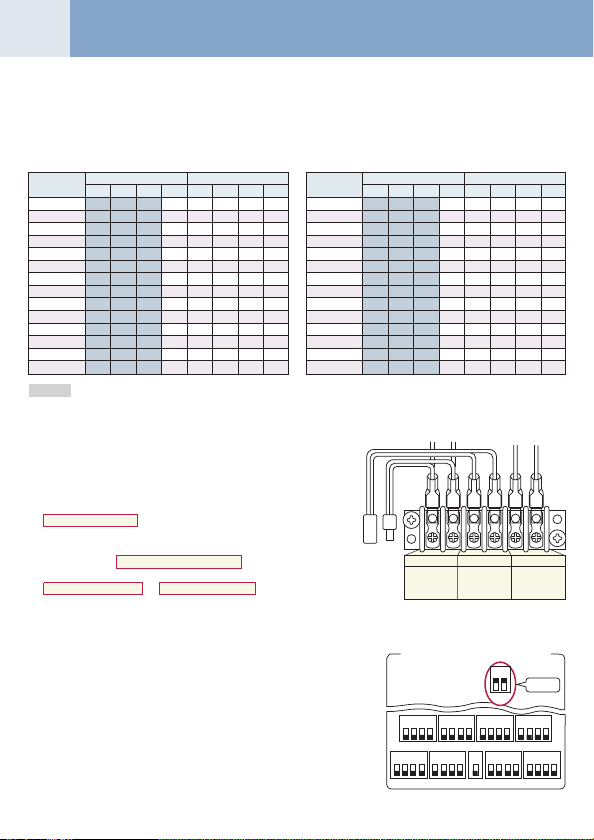
ON
1
2 3 4
1ON2 3 4
1ON2 3 4
1ON2 3 4
SW11
SW12
SW13
11 2 3 4
SW09SW08
SW14
1 2 3 4
SW10
ON ONON ON
1ON2 3 4
1
2 3 4
SW06
SW07
(Example)
Cabling systematic
diagram
Header unit interface P. C. board
SW04
SW05 SW15
D600 D601 D602 D603 D604
SW01
SW02 SW03
111
3
2, 4
5
U1 U2
U3 U4
For internal
wiring between
indoor and
outdoor
Group control over
multiple refrigerant lines
Outdoor
Indoor
Indoor
Remote
Remote
controller
controller
For wiring of
central control
system
Outdoor
Indoor
Remote
controller
For internal
wiring between
outdoor units
controller
U5 U6
Indoor
Remote
Page 12
Continued
U1 U2
For internal
wiring between
indoor and
outdoor
U3 U4
For wiring of
central control
system
U5 U6
2
For internal
wiring between
outdoor units
11
Address setup procedure 2
1. Using SW13 and 14 on the interface P. C. board of the outdoor unit in each system, set up the address for each system. (At shipment from factory: Set to Address 1)
Note) Be careful not to duplicate addresses with the other refrigerant line.
Line address switch on outdoor interface P.C. board
Line
address
1
2
3
4
5
6
7
8
9
10
11
12
13
14
SW13 SW14
12341234
ЧЧЧЧЧ
Ч ×××
¡
×× ××
¡
× ××
¡
¡
××× ×
× × ×
×× ×
× ×
××××
× ××
×× ×
× ×
×××
× ×
¡
¡ ¡
¡ ¡
¡
¡ ¡
¡ ¡
¡
¡¡¡
¡ ¡
¡ ¡
¡
¡
¡
Line
address
15
16
17
18
19
20
21
22
23
24
25
26
27
28
(¡ : Switch ON, × : Switch OFF)
SW13 SW14
12341234
××
¡ ¡ ¡
×
¡¡¡¡
××××
¡
×××
¡¡
× ××
¡¡
¡
×× ×
¡ ¡
× ×
¡ ¡¡
× ×
¡
¡¡
×××
¡
××
¡¡
× ×
¡
¡
¡
¡¡
: Is not used for setup of system address. (Do not change setup.)
2. Check that the relay connectors between [U1, U2] and [U3, U4]
terminals are not connected in all the outdoor units to which the
central control is connected.
(At shipment from factory: Connector not connected)
3. Tu rn on power of indoor/outdoor. (In order of indoor
4. After approx. 1 minute, check that 7-segment display is
U.1.L08 (U.1. flash) on the interface P.C. board of the outdoor unit.
5. Push SW15 to start the setup of automatic addressing.
(Max. 10 minutes for 1 line (Usually, approx. 5 minutes))
6. When the count Auto 1 ® Auto 2 ® Auto 3 is displayed in
7-segment display section, and it changes from
U. 1. - - - (U. 1. flash) to U. 1. - - - (U. 1. light) , the setup finished.
7. Procedure 4. to 6. are repeated in other refrigerant lines.
8. How to set up the terminal resistance
When all the address setups have finished in the same refrigerant
circuit system, put the terminal resistance in the same central
control line into one.
• Remain only SW30-2 of the header outdoor unit with address 1 as
ON. (With end terminal resistance)
• Set up SW30-2 of the other header outdoor units to OFF.
(Without terminal resistance)
9. Connect the relay connector between [U1, U2] and [U3, U4] of the
header unit for each refrigerant line.
10. Then set up the central control address.
(For the central control address setup, refer to the Installation
manual of the central control devices.)
®®
® outdoor)
®®
Header unit interface P. C. board
1ON2
SW30
1ON2 3 4
1ON2 3 4
1ON2 3 4
SW11
SW12
SW13
ON ONON ON
1ON2 3 4
1
2 3 4
11 2 3 4
SW06
SW07
SW09SW08
¡
××
¡¡
¡¡
×
SW30
1ON2 3 4
SW14
1 2 3 4
SW10
¡
×
¡
¡
¡
¡
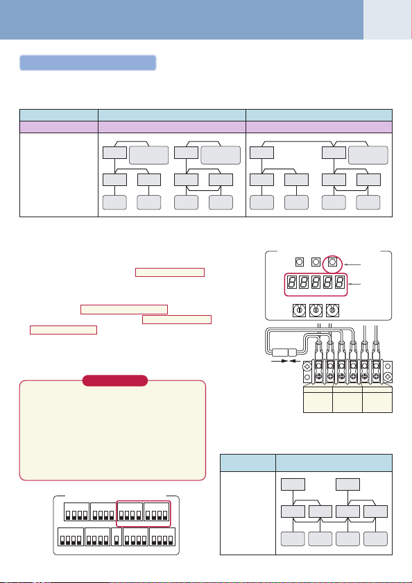
Page 13

11
Before address setup
During setup of address
After address setup
Outdoor interface
P.C. board
SW13, 14
(Refrigerant line address)
SW30-2
Terminal-end resistance of
indoor/outdoor communi
cation line/central control
communication line
Relay connector
Indoor side (Automatic setup)
Refrigerant line address
Indoor unit address
Group address
Relay
connector
1 2 3
U5 U6 U1 U2
U1 U2
controller
Individual
21
ON
OFF
U5 U6 U1
U1 U2
controller
Individual
Follower unitHeader unit
U3 U4
A B
Remote
Follower unitHeader unit
U3 U4
U2 U5 U6
A B
Remote
U5 U6
21
ON
OFF
Relay
connector
Relay
connector
U3 U4
U1 U2
U1 U2
A B
Remote
controller
Group
U3 U4
SW30 SW30
U1
U2
U1 U2
A B
Remote
controller
Group
U3 U4
U1 U2
U1 U2
A B
Remote
controller
U3 U4
SW30 SW30
U1
U2
U1 U2
A B
Remote
controller
Header unit Follower unit Follower unitHeader unit Header unit
1
ON
Connect short
after
address setup
1
1
0
(Setup is
unnecessary.)
(Setup is
unnecessary.)
Open
1
2
0
2 3
OFF after
address setup
Connect short
after
address setup
2
1
1
Follower unitHeader unit
U3 U4
U5 U6 U1 U2
U5 U6 U1
21
ON
OFF
U1 U2
A B
Follower unitHeader unit
U3 U4
U2 U5 U6
U1 U2
A B
(Setup is
unnecessary.)
(Setup is
unnecessary.)
U5 U6
21
ON
OFF
connector
Relay
Open Open
2
2
2
U3 U4
U1 U2
U1 U2
Remote
controller
U3 U4
SW30
U1
U2
U1 U2
Remote
controller
OFF after
address setup
Connect short
after
address setup
Header unit
U5 U6
A B
Header unit
21
U5 U6
A B
3
1
0
ON
OFF
Relay
connector
12
Setup at
shipment from
factory
1
ON
Never connect a relay connector until address setup for all the refrigerant lines has been completed ;
NOTE
otherwise address cannot be correctly set up.
Page 14

Continued
13
Manual address setup from remote controller
In case to decide an address of the indoor unit prior to finish of indoor wiring work and unpracticed outdoor wiring work
(Manual setup from remote controller)
Arrange one indoor unit and one remote controller set to 1 by 1.
Turn on the power.
(Wiring example in 2 lines)
#1
Outdoor
Indoor Indoor Indoor
Line address ® 1
Indoor address ® 1
Group address ® 1
In the above example, under condition of
no inter-unit wire of the remote controller,
set the address after individual connecting of the wired remote controller.
Group address
Individual : 0000
Header unit : 0001
Follower unit : 0002
Operation procedure
Remote
controller
Header
In case of group control
}
#2
Outdoor
Indoor Indoor
1
1
2
2
3
1
2
2
2
Follower
1 ® 2 ® 3 ® 4 ® 5 ® 6
7 ® 8 ® 9 ® 10 ® 11
2,
5,
8
SET
Data Item code
4,
FILTER
11
7,
RESET
End
DATA
SETTING
UNIT No.
R.C. No.
TEMP.
FAN
TIMER SET
SWING/FIXTIME
UNITSET CL
TEST
10
1 Push si multaneously
more.
LCD changes to flashing.
(Line address)
2 Using the setup temp. / buttons, set
item code.
3 Using the timer time / buttons, set up the line ad-
dress.
(Match it with the line address on the interface P.C. board of the
outdoor unit in the identical refrigerant line.)
SET
4 Push
button.
(OK when display goes on.)
5 Using the setup temp. / buttons, set
item code.
6 Using the timer time / buttons, set up the indoor
address.
SET
7 Push
button.
(OK when display goes on.)
8 Using the setup temp. / buttons, set
item code.
9 Using the timer time / buttons, set Individual =
Header unit =
SET
button.
(OK when display goes on.)
TEST
button.
Setup operation finished. (Status returns to normal stop status.)
3,
6,
®
ON / OFF
2
2
2
CODE No.
MODE
VENT
(Indoor address)
(Group address)
10 Push
11 Push
9
1
SET
TEST
+ CL +
buttons for 4 seconds or
12
to the
13
to the
14
to the
0001
, Follower unit =
Note 1)
When setting the line address from the remote
controller, do not use address 29 and 30.
The address 29 and 30 cannot be set up in the
outdoor unit. Therefore if they are incorrectly set up,
a check code [E04] (Indoor/outdoor communication
circuit error) is output.
0002
0000
.
,
Page 15

Clearance of address (Return to status (Address undecided) at shipment from factory)
Method 1
An address is individually cleared from a wired remote controller.
“0099” is set up to line address, indoor address, and group address data from the remote controller.
(For the setup procedure, refer to the abovementioned address setup from the remote controller.)
Method 2
Clear the indoor addresses in the same refrigerant line from the outdoor unit.
1. Tu rn off the power of the refrigerant line to be returned to the status at shipment, and change the header unit to the
following status.
1) Remove the relay connector between [U1U2] and [U3U4].
(If it has been already removed, leave it as it is.)
2) Turn on SW30-2 on the interface P. C. board of the header unit if it is OFF.
(If it has been already ON, leave it as it is.)
Central control
device
U1U3U2
Header unit
2. Tu rn on the indoor/outdoor power of which address is to be cleared. After approx. 1 minute, check that “U.1. - - -” is
displayed, and then execute the following operation on the interface P. C. board of the header unit of which address is
to be cleared in the refrigerant line.
SW01 SW02 SW03
212
222
3. After “A.d. c.L.” has been displayed on 7-degment display, return SW01/SW02/SW03 to 1/1/1.
4. When the address clearing has correctly finished, “U.1.L08” is displayed on 7-degment display after a while.
If “A.d. n.G.” is displayed on 7-degment display, there is a possibility which is connected with the other refrigerant line.
Check again the relay connector between [U1U2] and [U3U4] terminals.
Note) Be careful that the other refrigerant line address may be also cleared if clearing operation is not correctly
executed.
5. After clearing of the address, set up an address again.
U3 U4
U1 U2 U5 U6
U1 U2
A B
Remote
controller
Follower unit
U1 U2 U5 U6
U1 U2
A B
Remote
controller
Center unitCenter unit Center unitCenter unitHeader unit Header unit
U3 U4
Unit of which address is to be returned to the initial status
U3 U4
U1 U2 U5 U6
U1 U2
A B
Remote
controller
Follower unit
U1 U2 U5 U6
U1 U2
A B
SW04
After checking that “A.d.buS” is displayed on 7-degment
display, and then push SW04 for 5 seconds or more.
After checking that “A.d.nEt” is displayed on 7-degment display,
and then push SW04 for 5 seconds or more.
U3 U4
U1 U2 U5 U6
U1 U2
U4
U3 U4
A B
Remote
controller
Address which can be cleared
Line + Indoor + Group address
Central address
14
Page 16

Troubleshooting in Test Operation
15
If the phenomena appear, such as a check code is output or the remote controller is not accepted in power-ON after cabling work or
in address setup operation, the following causes are considered.
1 A check code is displayed on the remote controller
Check code
displayed on
remote controller
(*) [L05] : Displayed on the indoor unit set up with priority
Outdoor unit
E04
E16
E25
L04
L05 (*)
L06 (*)
L08
7-segment
display
E19-00
Outdoor power is formerly turned on.
There is none of outdoor terminator resistor, or there are
two or more resistances. (After address setup)
After address was decided, all the
indoor units do not correctly response
after power-ON in outdoor unit.
L08
Address setup error
•Only line addresses of the connected indoor units are
undefined.
• The outdoor line address and the line addresses in all
indoor units do not match.
• The indoor addresses are duplicated.
(Units except those displaying E04 are duplicated.)
•A header unit is not set up in a group.
(Except group displaying E04)
E08-XX
Duplication of indoor addresses.
(Address No in which sub-code of the check code are
duplicated)
E07
There is none of outdoor terminal
resistance, or there are two or more
resistances.
(After address setup, when terminal
resistance setup is changed after
power-ON.)
Transmission circuit error at interface side
(P.C. board failure)
E06
After address setup, communication from all the indoor
units interrupted under condition that a normal operation
can be performed.
Exceeded No of connected indoor units or exceeded
E16-XX
capacity.
Duplication of outdoor addresses.
E25
(Only when outdoor address was manually set up)
Duplication of outdoor line addresses
L04
•Line address setup error, occurred after connection
between U1, U2 and U3, U4 connectors
Duplicated of indoor units with priority
L06
There are two or more indoor units set up with priority.
Address setup error
L08
•Only indoor addresses of all the connected indoor units
are undefined.
Cause
ON
ON
SW30
1
SW30
1
2
[L06] : Displayed on the indoor unit except one set up with priority
Countermeasures
Turn on the power again.
(In order of Indoor ® Outdoor)
Check SW30 bit 2 of the outdoor unit.
No connection between multiple refrigerant lines: SW30 bit
20N
Connection between multiple refrigerant lines: SW30 bit 2
of the connected outdoor unit is turned on only in one line.
2
Check and modifies disconnection of indoor/outdoor
communication line. (Communication line between outdoor
unit and the leading indoor unit)
Check influence of communication noise.
Set up address again.
Set up address again.
Check SW30 bit 2 of the outdoor unit.
No connection between multiple refrigerant lines: SW30 bit
20N
Connection between multiple refrigerant lines: SW30 bit 2
of the connected outdoor unit is turned on only in one line.
Replace the interface P. C. board.
Check and correct disconnection of indoor/outdoor
communication line.(Communication line between outdoor
unit and the leading indoor unit)
Check influence of communication noise.
Adjust No of connected indoor units or capacity.
Do not use a manual setup for outdoor address.
Modify line address setup of the outdoor unit between
lines. (Set up SW 13 and 14 on the interface P. C. board.)
The Heat Recovery Multi is not set up on priority.
Set up address again.
Page 17

2 Operation from remote controller is not accepted and a check code is displayed on 7-segment
display of the interface P.C. board of the outdoor unit.
7-segment
Remote
controller status
No response
3 There is no display of a check code on 7-segment display on the interface P.C. board of the outdoor
controller status
No response
No display on
remote controller
(No line is output.)
4 In check for No. of connected outdoor units and connected Indoor units after address setup,
Number of
connected outdoor
units is short.
Number of
connected indoor
units is short.
Number of outdoor
units connected to
group is short in
group operation
from remote
controller.
display of
outdoor unit
L08
Line addresses and indoor addresses of all the connected indoor
units are unset.
There is no outdoor unit of group control.
E19-00
Indoor unit power is not turned on.
Indoor/outdoor communication line is not correctly connected to
the outdoor unit.
(Indoor/outdoor cannot communicate before address setup.)
There is none of outdoor terminator resistor,
or there are two or more resistances.
(Before address setup)
E20-01
Address setup is performed with connecting indoor/outdoor
communication line between outdoor units.
Address setup is performed under condition of connecting
between multiple refrigerant lines.
unit though there is indoor unit which does not accept the operation from the remote controller.
7-segment
Remote
display of
outdoor unit
None
Communication line is not connected between indoor and
outdoor.
Line and indoor addresses are unset.
(Unit which does not response to remote controller)
The power of the header unit of the group is not turned on in
indoor group control.
(Unit which does not response to remote controller)
Group address is set up to follower unit in the individual control.
(Unit which does not response to remote controller)
None
The power is not turned on.
(Unit which is not displayed on remote controller)
Remote controller is not connected with cable.
(Unit which is not displayed on remote controller)
Miscabling of remote controller
(Unit which is not displayed on remote controller)
Remote controller communication circuit error
(Unit which is not displayed on remote controller)
If 230V is incorrectly applied to the remote controller terminal, the
remote controller communication circuit fails.
diminished No. of connected units displayed.
(There are outdoor/indoor units which do not operate in a test operation.)
Status
Miswiring of communication line between
outdoor units or unconnected cable.
(Address setup operation has finished without
recognition of miswired follower unit.)
Miswiring of communication line between indoor
units or unconnected cable.
(Address setup operation has finished without
recognition of miswired indoor unit.)
Remote controller is not connected with wire.
Miscabling of remote controller
Remote controller communication circuit error
If 230V is incorrectly applied to the remote
controller terminal, the remote controller
communication circuit fails.
Cause
Cause
Set up addresses.
Set up group address.
Turn on the power again.
(In order of indoor ® outdoor)
Correct wiring.
Check SW30 bit 2 of the outdoor unit.
ON
No connection between multiple refrigerant lines: SW30
1
2
bit 2 0N
Connection between multiple refrigerant lines: SW30 bit 2
of the connected outdoor unit is turned on only in one line.
SW30
Correct wiring.
Correct wiring.
Cause
Modify wiring.
Set up address.
Turn on the power.
Set [0] to group address in case of individual control.
Turn on the power.
Correct wiring.
Correct wiring.
Remove FASTON terminal connected to remote controller
terminals (A/B), and check the voltage.
If voltage is not applied, replace P. C. board.
(15 to 18V usually)
After modification of wiring, set up address again and check No. of the connected
outdoor units.
After modification of wiring, set up address again and check No. of the connected
indoor units.
Using the main remote controller connected to a group, start a test operation, specify
the unit which does not operate (Unit unconnected to group), and then check wiring.
Using the main remote controller connected to a group, start a test operation, specify
the unit which does not operate (Unit unconnected to group).
Remove Fasten receptacle connected to remote controller terminals (A/B), and check
the voltage. If voltage is not applied, replace P. C. board. (15 to18V in normal time)
Countermeasures
Countermeasures
Countermeasures
16
Page 18

Monitor Function of Remote Controller Switch
17
n When using a remote controller with the model name RBC-ATM21E, the following monitor
functions can be used.
<Calling of display screen>
[Contents]
The temperature or the operation status of the remote controller, indoor
unit, or each sensor of the outdoor unit can be known by calling up the
service monitor mode from the remote controller.
[Procedure]
CL
1 Push
2 Push the temperature setup / buttons to select the
3 Push
4 Pushing
TEST
+
to call up the service monitor mode.
The service monitor goes on, and temperature of the item
code
item number (Item code) to be monitored.
For displayed codes, refer to the table below.
Then monitor the indoor unit and sensor temperature or
operation status in the corresponding refrigerant line.
buttons simultaneously for 4 seconds or more
00
is firstly displayed.
UNIT
button to change the item to one to be monitored.
TEST
button returns the display to the normal display.
TEMP.
4
TIMER SET
FILTER
TEST
RESET
1
Operation procedure
1 ® 2 ® 3 ® 4
Returns to the normal display
CODE No.
UNIT No.
ON / OFF
FAN
MODE
SWING/FIXTIME
VENT
UNITSET CL
2
3
Item
code
00
01
02
03
04
05
Indoor unit data (NOTE 2)System data
06
08
0A
0b
0C
0d
Note 1) Only a part of indoor unit types is installed with the discharge temperature sensor.
Note 2) When the units are connected to a group, data of the header indoor unit only can be displayed.
Note 3) 01 : Compressor 1 only is ON. 10 : Compressor 2 only is ON. 11 : Both compressor 1 and 2 are ON.
Note 4) The item codes are described as the example of the header unit.
Note 5) The upper digit of an item code represents the outdoor unit number.
Data name
Room temp (During control)
Room temp (Remote controller)
Indoor suction temp (TA)
Indoor coil temp (TCJ)
Indoor coil temp (TC2)
Indoor coil temp (TC1)
Indoor discharge temp (Tf) Note 1)
Indoor PMV opening
No. of connected indoor units
Total HP of connected indoor units
No. of connected indoor units
Total HP of outdoor units
This temperature is not displayed for other types.
1 : Header unit (A) 2 : Follower unit (B) 3 : Follower unit (C)
Unit
pulse
Display
Item
format
code
10
°C
°C
°C
× 1
°C
× 1
°C
× 1
°C
× 1
°C
× 1
× 1/10
unit
HP
× 10
unit
HP
× 10
Compressor 1 discharge temp (Td1)
11
Compressor 2 discharge temp (Td2)
12
High-pressure sensor detention pressure (Pd)
13
Low-pressure sensor detention pressure (Ps)
14
Suction temp (TS)
15
Outdoor heat exchanger temp (TE)
16
Temp at liquid side (TL)
17
Outside ambient temp (TO)
18
Low-pressure saturation temp (TU)
19
Compressor 1 current (I1)
1A
Compressor 2 current (I2)
Outdoor unit individual data (NOTE 4, 5)
1b
PMV1 + 2 opening
1d
Compressor 1, 2 ON/OFF
1E
Outdoor fan mode
1F
Outdoor unit HP
Data name
Unit
MPa
MPa
pulse
HP
Display
°C
°C
°C
°C
°C
°C
°C
A
A
—
—
format
× 1
× 1
× 100
× 100
× 1
× 1
× 1
× 1
× 1
× 10
× 10
× 1/10
Note 3)
0 to 31
× 1
Page 19

Confirmation of indoor unit address and position by using the remote controller
[Confirmation of indoor unit address and the position]
1 When you want to know the indoor address though position of the indoor unit itself can be
recognized;
<Procedure> (Operation while the air conditioner operates)
1 If it stops, push
2 Push
The unit No.
(Disappears after several seconds)
The displayed unit No indicates the line address and indoor
address.
(If there is other indoor unit connected to the same remote
controller (Group control unit), other unit No. is displayed every
pushing
UNIT
button.
1-1
is displayed on the LCD.
UNIT
button.)
ON / OFF
button.
1
Operate
UNIT No.
TEMP.
FAN
TIMER SET
SWING/FIXTIME
FILTER
RESET
UNITSET CL
TEST
ON / OFF
CODE No.
MODE
VENT
18
2
2 When you want to know position of the indoor unit using the address
• To confirm the unit numbers in a group control;
<Procedure> (Operation while the air conditioner stops)
The indoor unit numbers in a group control are successively displayed,
and the corresponding indoor fan is turned on.
(Operation while the air conditioner stops)
VENT
1 Push
or more.
• Unit No. is displayed.
• The fans of all the indoor units in a group control are turned
2 Every pushing
the
group control are successively displayed.
• The firstly displayed unit No. indicates the address of the
• Only fan of the selected indoor unit is turned on.
3 Push
All the indoor units in group control stop.
TEST
+
buttons simultaneously for 4 seconds
on.
UNIT
button, the indoor unit numbers in
header unit.
TEST
button to finish the procedure.
1
3
2
End
Operation procedure
1 ® 2
TIMER SET
CODE No.
UNIT No.
R.C. No.
ON / OFF
FAN
SWING/FIXTIME
UNITSET CL
End
DATA
SET
SETTING
TEMP.
FILTER
TEST
RESET
Operation procedure
1 ® 2 ® 3
MODE
VENT
Page 20

Continued
19
•To confirm all the unit numbers from an arbitrary wired remote controller;
<Procedure> (Operation while the air conditioner stops)
The indoor unit No. and position in the same refrigerant line can be confirmed.
An outdoor unit is selected, the indoor unit numbers in the same refrigerant line are successively displayed, and then its
indoor unit fan is turned on.
1 Push the timer time +
seconds or more.
Firstly, the line 1, item code AC (Address Change) is displayed.
(Select outdoor unit.)
UNIT
2 Using
3 Using
4 Every pushing
[To select another line address]
5 Push
6 Push
+
SET
button, determine the selected line address.
• The indoor unit address, which is connected to the refrigerant pipe
of the selected outdoor unit is displayed and the fan is turned on.
identical pipe are successively displayed.
• Only fan of the selected indoor unit operates.
CL
button to return to procedure 2 ).
• The indoor address of another line can be successively confirmed.
TEST
button to finish the procedure.
TEST
buttons simultaneously for 4
SWING/FIX
buttons, select the line address.
UNIT
button, the indoor unit numbers in the
DATA
SET
TEMP.
1
FILTER
TEST
RESET
6
3
Operation procedure
1 ® 2 ® 3 ®
4 ® 5 ® 6
TIMER SET
CODE No.
UNIT No.
R.C. No.
ON / OFF
FAN
MODE
SWING/FIXTIME
VENT
UNITSET CL
End
SETTING
Change of indoor address from remote controller
Change of indoor address from wired remote controller
•To change the indoor address in individual operation (Wired remote controller : Indoor unit = 1 : 1) or
group control (When the setup operation with automatic address has finished, this change is available.)
<Procedure> (Operation while air conditioner stops)
1 Push simultaneously
(The firstly displayed unit No. indicates the header unit in group control.)
2 In group control, select an indoor unit No. to be changed by
UNIT
button.
(The fan of the selected indoor unit is turned on.)
3 Using the setup temp. / buttons, set
code.
4 Using the timer time / buttons, change the displayed
setup data to a data which you want to change.
SET
5 Push
6 Using the
7 After the above change, push
button.
the next time. Repeat the procedure 4 to 6 and change the
indoor address so that it is not duplicated.
changed contents.
8 If it is acceptable, push
SET
TEST
+ CL +
buttons for 4 seconds or more.
13
to the item
UNIT
button, select the unit No. to be changed at
UNIT
button to confirm the
TEST
button to finish confirmation.
DATA
SET
SETTING
TEMP.
3
5
FILTER
TEST
RESET
8
1
Operation procedure
1 ® 2 ® 3 ® 4
5 ® 6 ® 7 ® 8
TIMER SET
CODE No.
UNIT No.
R.C. No.
ON / OFF
FAN
MODE
SWING/FIXTIME
VENT
UNITSET CL
®
End
2
4
5
4
2,
6,
7
Page 21

20
•To change all the indoor addresses from an arbitrary wired remote controller;
(When the setup operation with automatic address has finished, this change is available.)
Contents :Using an arbitrary wired remote controller, the indoor unit address can be changed for each same refrigerant line
* Chang e the address in the address check/change mode.
<Procedure> (Operation while air conditioner stops)
1 Push the timer time +
Firstly, the line 1, item code AC (Address Change) is displayed.
UNIT
2 Using
3 Push
4 The indoor address of the setup data moves up/down by the timer time / buttons.
5 Push
6 Every pushing
7 Push
8 Push
+
SET
button.
• The indoor unit address, which is connected to the refrigerant pipe of the selected outdoor unit is displayed and the
fan is turned on.
First the current indoor address is displayed on the setup data. (Line address is not displayed.)
Change the setup data to a new address.
SET
button to determine the setup data.
Only fan of the selected indoor unit operates.
Repeat the procedure 4 to 6 and change all the indoor addresses so that they are not duplicated.
SET
button.
(All the displays on LCD go on.)
TEST
button to finish the procedure.
TEST
buttons simultaneously for 4 seconds or more.
SWING/FIX
buttons, select the line address.
UNIT
button, the indoor unit numbers in the identical pipe are successively displayed.
DATA
SET
SETTING
TEMP.
TIMER SET
FILTER
1
TEST
RESET
3
Here, if the unit No is not called up, the outdoor unit in this line
does not exist.
Push CL button, and then select a line according to procedure 2 .
CODE No.
UNIT No.
R.C. No.
ON / OFF
FAN
MODE
SWING/FIXTIME
VENT
UNITSET CL
Cancel of line selection
2
DATA
SET
SETTING
TEMP.
4
FILTER
TEST
RESET
8
5, 7
Operation procedure
1 ® 2 ® 3 ® 4 ®
5 ® 6 ® 7 ® 8
TIMER SET
UNIT No.
R.C. No.
CODE No.
ON / OFF
FAN
MODE
SWING/FIXTIME
VENT
UNITSET CL
To finish the set
End
6
Page 22

Error Clearing Function
21
Clearing from the main remote controller
n [Error clearing in outdoor unit]
Error of the outdoor unit is cleared by the unit of one refrigerant circuit system to which the indoor units operated by
the remote controller. (Error of the indoor unit is not cleared.)
For clearing errors, the service monitor function of the remote controller is used.
<Method>
CL
1 Change the mode to service monitor mode by pushing
or more.
2 Using / buttons, set
The display in Section A in the following figure is counted with interval of 5 seconds as
“
0005
” → “
0004
When the count arrives “
*However, counting from “
TEST
3 When
” → “
button is pushed, the status returns to the normal status.
to item code.
“FF”
0003
” → “
0000
0002
”, the error is cleared.
0005
” is repeated on the display.
” → “
0001
TEST
+
buttons simultaneously for 4 seconds
” → “
0000
”.
Operation procedure
1 ® 2 ® 3
The status returns to the normal status.
CODE No.
Section A
3
UNIT No.
R.C. No.
TEMP.
FILTER
TEST
RESET
TIMER SET
ON / OFF
FAN
MODE
SWING/FIXTIME
VENT
UNITSET CL
1
n [Error clearing in indoor unit]
Error in the indoor unit is cleared by
(Only error of the indoor unit connected with operating remote controller is cleared.)
ON / OFF
button on the remote controller.
2
Page 23

Applied control
Setup of Selecting Function in Indoor Unit
(Be sure to Execute Setup by a Wired Remote Controller)
<Procedure> Execute the setup operation while the unit stops.
SET, CL
1 Push
The firstly displayed unit No. indicates the master indoor unit address in the group control.
In this time, the fan of the selected indoor unit is turned on.
2 Every pushing
In this time, the fan of the selected indoor unit only is turned on.
3 Specify the item code (DN) using the setup temperature
and buttons.
4 Select the setup data using the timer time and buttons.
(When selecting the DN code to “33”, change the temperature
indication of the unit from “°C” to “°F” on the remote controller.)
5 Push
•To change the selected indoor unit, return to procedure 2 .
•To change the item to be set up, return to procedure 3 .
6 Pushing
TYPE
Item code [10]
Setup data
0000
0001
0002
0003
0004
0005
0006
0007
0008
0010
0011
0013
~
TEST
, and
buttons simultaneously for 4 seconds or more.
UNIT
button, the indoor unit numbers in the group control are successively displayed.
SET
button. (OK if display goes on.)
TEST
button returns the status to normal stop status.
1-way Air Discharge Cassette
4-way Air Discharge Cassette
2-way Air Discharge Cassette
1-way Air Discharge Cassette (Compact type)
Concealed Duct Standard
Slim Duct
Concealed Duct High Static Pressure
Under Ceiling
High Wall
Floor Standing Cabinet
Floor Standing Concealed
Floor Standing
Type
—
3
5
6
1
Abbreviated Model name
MMU-AP XXX SH
MMU-AP XXX H
MMU-AP XXX WH
MMU-AP XXX YH
MMD-AP XXX BH
MMD-AP XXX SPH, SH
MMD-AP XXX H
MMC-AP XXX H
MMK-AP XXX H
MML-AP XXX H
MML-AP XXX BH
MMF-AP XXX H
UNIT No.
TEMP.
TIMER SET
SWING/FIXTIME
FILTER
TEST
RESET
Indoor unit capacity
Item code [11]
Setup data
0001
0003
0005
0007
0009
0011
0012
0013
0015
0017
0018
0021
0023
~
22
CODE No.
ON / OFF
FAN
MODE
4
VENT
UNITSET CL
2
Model
007
009
012
015
018
024
027
030
036
048
056
072
096
—
Page 24

Continued
23
(Items necessary to perform the applied control at the local site are described.)
DN
01
02
03
04
06
0d
0E
0F
10
11
12
13
14
19
1E
28
29
2A
2E
30
31
32
33
40
5d
60
62
Item
Filter display delay timer
Dirty state of filter
Central control address
Specific indoor unit priority
Heating temp shift
Existence of [AUTO] mode
Follows operation mode of the
header unit
Cooling only
Type
Indoor unit capacity
Line address
Indoor unit address
Group address
Louver type
(Adjustment of air direction)
Temp difference of [AUTO] mode
selection
COOL ® HEAT, HEAT ®COOL
Automatic restart of power failure
Operation condition of humidifier
Selection of option/error input
(CN70)
HA terminal (CN61) select
Automatic elevating grille
Ventilating fan control
TA sensor selection
Temperature unit select
Drain pump control
High ceiling selection
(Air volume selection)
Timer set
(Wired remote controller)
Anti-ceiling
smudging control
Table: Function selecting item code (DN)
0000 : None 0001 : 150H
0002 : 2500H 0003 : 5000H
0004 : 10000H
0000 : Standard
0001 :High degree of dirt (Half of standard time)
0001 :No.1 unitto0064 :No.64 unit
0099 : Unfixed
0000 :No priority 0001 :Priority
0000 : No shift 0001 : +1°C
0002 : +2°Cto0010 : +10°C (Up to +6 recommended)
0000 : Provided
0001 : Not provided (Automatic selection from connected outdoor unit)
0000 :Does not follow
0001 :Follows
0000 : Heat pump
0001 : Cooling only (No display of [AUTO] [HEAT])
0000 :(1-way air discharge cassette)
0001 :(4-way air discharge cassette) to 0037
0000 : Unfixed 0001 to 0034
0001 :No.1 unitto0030 :No.30 unit
0001 :No.1 unitto0064 :No.64 unit
0000 :Individual 0001 : Header unit of group
0002 :Follower unit of group
0000 : Not provided 0001 :Swing only
0004 : [4-way Air Discharge Cassette type] and [Under Ceiling type]
0000 :0 deg to 0010 : 10 deg
(For setup temperature, reversal of COOL/HEAT by ± (Data value)/2)
0000 : None 0001 : Restart
0000 : Usual
0001 :Condition ignored (Detection control for heat exchanger temperature)
0000 : Filter input 0001 :Alarm input (Air washer, etc.)
0002 : None
0000 : Usual 0001 : Leaving-ON prevention control
0000 : Unavailable0001 :Available
0000 : Unavailable0001 :Available
0000 : Body TA sensor 0001 : Remote controller sensor
0000 : °C (at factory shipment)0001 :°F
0000 : None 0001 : Pump ON
0002 : None 0003 : Pump OFF
[4-way Air Discharge Cassette type] and [Under Ceiling type]
0000 :Standard filter0001 : Super-long life filter
0003 :High efficiency filter
[Concealed Duct Standard type]
0000 : Standard static pressure (40Pa)
0001 : High static pressure 1 (70Pa)
0003 :High static pressure 2 (100Pa)
0005 :Correspond to quiet sound
0006 :Low static pressure (20Pa)
0000 :Ava ilable (Operable)
0001 :Unavailable (Operation prohibited)
0000 :Clear
Description
At shipment
According to type
0000 : Standard
0099 : Unfixed
0000 : No priority
0002 : +2°C
(Floor type 0000: 0°C)
0001 : Not provided
0000 : Not provided
0000 : Heat pump
According to model type
According to capacity type
0099 : Unfixed
0099 : Unfixed
0099 : Unfixed
According to type
0003 :3 deg
(Ts±1.5)
0000 : None
0000 : Usual
0002 : None
0000 :Usual (HA terminal)
0000 : Unavailable
0000 : Unavailable
0000 : Body TA sensor
0000 :°C
0003 : Pump OFF
0000 : Standard
0000 :Available
4- way Air Discharge
Cassette type only
Page 25

Service Support Function
n Function to start/stop (ON/OFF) indoor unit from outdoor unit
The following functions enables the start and stop of the indoor units using the switches on the interface P.C. board of
the header unit.
No.
Function
1
All cooling
Changes the mode of all the connected indoor
test operation
units collectively to cooling test operation.
Note) Control operation same as test operation
2
All heating
Changes the mode of all the connected indoor
test operation
units collectively to heating test operation.
Note) Control operation same as test operation
3
Batch start
Starts all the connected indoor units collectively.
Note) The contents follow the setup of remote
Batch stop
Stops all the connected indoor units collectively.
4
Individual
Starts the specified indoor unit.
start
Notes)
• Control operation same as test.
• The other indoor units keep existing status.
Stops the specified indoor unit.
Individual
stop
Note) The other indoor units keep existing
Operates the specified indoor unit.
Individual test
operation
Note) The other indoor units keep existing
Note 1) This start/stop function only sends the
command signals from the outdoor unit to
the indoor unit, such as start, stop, operation
mode, etc.
Once it does not resend the signals even if
the indoor unit does not follow the sent
signals.
Note 2) The above controls are not available when
an error has caused the system to stop.
Outline
for remote controller.
for remote controller.
controller.
status.
status.
Setup/Release
[Setup]
Push SW04 for 2 seconds or more with
SW01”2”, SW02”5”, SW03”1”.
[Release]
Return SW01, SW02, SW03 to “1”.
[Setup]
Push SW04 for 2 seconds or more with
SW01”2”, SW02”6”, SW03”1”.
[Release]
Return SW01, SW02, SW03 to “1”.
[Setup]
Push SW04 for 2 seconds or more with
SW01”2”, SW02”7”, SW03”1”.
[Release]
Return SW01, SW02, SW03 to “1”.
[Setup]
Push SW05 for 2 seconds or more with
SW01”2”, SW02”7”, SW03”1”.
[Release]
Return SW01, SW02, SW03 to “1”.
[Setup]
Push SW04 for 2 seconds or more set
SW01 “16” and set SW02 and SW03 to
address No. (1 to 64) to be started.
[Release]
Return SW01, SW02, SW03 to “1”.
[Setup]
Push SW05 for 2 seconds or more set
SW01 “16” and set SW02 and SW03 to
address No. (1 to 64) to be stopped.
[Release]
Return SW01, SW02, SW03 to “1”.
[Setup]
Push SW04 for 10 seconds or more set
SW01 “16” and set SW02 and SW03 to
address No. (1 to 64) to be operated.
[Release]
Return SW01, SW02, SW03 to “1”.
Interface P.C. board
7-segment display [A]
7-segment display
Section A Section B
[C ][ –C]
Section A Section B
[H ][ –H]
Section A Section B
[CH] [ 11]
[ 11] is displayed on Section
B for 5 seconds.
Section A Section B
[CH] [ 00]
[ 00] is displayed on Section
B for 5 seconds.
Section A Section B
[ ][ ]
Section A:
Displays the corresponding
indoor address.
Section B:
Displays [ 11] for 5 seconds
from operation-ON.
Section A Section B
[ ][ ]
Section A:
Displays the corresponding
indoor address.
Section B:
Displays [ 00] for 5 seconds
from operation-OFF.
Section A Section B
[ ][ ]
Section A:
Displays the corresponding
indoor address.
Section B:
Displays [ FF] for 5 seconds
from test operation-ON.
7-segment display [B]
SW04 SW05
SW01 SW02 SW03
Rotary switch
24
Page 26

Continued
25
1 Data display of system information (Displayed on the header outdoor unit only)
SW011SW02
SW03
1
3
Refrigerant name Displays refrigerant name.A B
2
System capacity A[ 5] to [48] : 5 to 48HP
3
No. of outdoor units A[ 1] to [ 4] : 1 to 4 units
4
No. of connected indoor units/ A[ 0] to [48] : 0 to 48 units (No. of connected units)
No. of units with cooling thermo ON
5
No. of connected indoor units/ A[ 0] to [48] : 0 to 48 units (No. of connected units)
No. of units with heating thermo ON
6
Compressor command A Data is displayed with hexadecimal notation
correction amount
7
Release control A Normal time : [ r], During release control: [r1]
8
Oil-equalization control A Nor mal time : [oiL-0]
9
Oil-equalization request A Displays with segment LED lighting pattern
Refrigerant/oil recovery operation A During sending of cooling refrigerant oil recovery signal : [C1].
10
Automatic address A [Ad]
11
Demand operation A[dU]
12
Optional control (P.C. board input) Displays optioned control status AB
13
Option control (BUS line input) Same as above
14
Unused
15
16
—A —
Display contents
Model with refrigerant R410A r4 10A
Model with refrigerant R407C r4 07C
B [HP]
B[ P]
B [C0] to [C48] : 0 to 48 units (No. of units with cooling thermo ON)
B [H0] to [H48] : 0 to 48 units (No. of units with heating ther mo ON)
B
B —
B During oil equation : [oiL-1]
B
Display A Display B
A
FB
G
EC
Dp
D
U2 U3 U4
Normal time : [C ]
B During sending of heating refrigerant oil recovery signal : [H1].
Normal time : [H ]
BAutomatic addressing : [FF], Normal time : [ ]
B Normal time : [ ]. In 50% to 90% : [ 50 to 90]
When controlling by communication line input : [E50 to E90]
Operation mode selection : In heating with priority (Normal) h.**.*.*.
Priority on cooling c.**.*.*.
Heating only H.**.*.*.
Cooling only C.**. *.*.
Priority on No. of operating indoor units n.**.*.*.
Priority on specific indoor unit U.**.*.*.
Batch start/stop : Normal *.…. *.* .*.
Start input *.1. *.*.*.
Stop input *.0. *.*.*.
Night low-noise operation : Normal *.*.….*.*.
Operation input *.*.1.*.*.
Snow fan operation : Normal *.*. *.….*.
Operation input *.*. *.1.*.
B—
F in the left figure goes on:
Header requests oil equalization.
C in the left figure goes on:
Follower requests oil-equalization.
(Outdoor unit number)
* mark: Indicates none on display
Page 27

2 Data display of outdoor unit information (Displayed on each outdoor unit)
SW011SW02
SW03
1
1
Error data A Displays outdoor unit number: [U1] to [U4]
<SW04> push function : Fan of unit with error only drives. 7-segment A: [E1]
<SW04 + SW05> push function : Fan of normal unit only drives. 7-segment A: [E0]
2
3
Operation mode A Stop: [ ]
4
Outdoor unit HP A 5HP: [ 5], 6HP: [ 6], 8HP: [ 8], 10HP: [10], 12HP: [12]
5
Compressor operation command ANo.1 compressor operation command is displayed.
6
Outdoor fan step A[FP]
7
Compressor backup A Displays No.1 compressor setup status
8
9
Control valve output data Displays control output status of solenoid valveAB
10
11
12
13
14
PMV1 /PMV2 opening Displays opening data (Decimal) (Totalopening) * ** *. P
15
16
Oil level judgment status A [oL]
<SW05> push function : Interruption of fan operation function
—A —
<SW04> push function : Inverter frequency is exchanged to decimal notation.
7-segment display (A/B) : [* * ] [* * H] (Nor mal display by pushing <SW05>)
—A —
— —… ** *. P
Display contents
B Displays check code (Latest code only is displayed.)
There is no check code: [– – –]
There is sub-code: Check code [* * *] for 3 seconds, sub-code [– * *] for
1 second alternately
B —
Normal cooling: [ C], Normal heating: [ H], Normal defrost: [ J]
B —
B [HP]
Data display with Hexadecimal notation: [00 to FF]
BNo.2 compressor operation command is displayed.
Data display with Hexadecimal notation: [00 to FF]
B Step 0 to 31: [ 0 to 31]
Normal: [ ], Backup setup: [C1]
B Displays No.2 compressor setup status
Normal: [ ], Backup setup: [C2]
B—
4-way valve: ON H. 1… … …
4-way valve: OFF H. 0… … …
SV2: ON / SV5: OFF 2. 1… 5. 0
SV2: OFF / SV5: ON 2. 0… 5. 1
SV3A: ON / SV3B: OFF / SV3C: OFF /SV3D: OFF 3. 10 0 0
SV3A: OFF / SV3B: ON / SV3C: OFF /SV3D: OFF 3. 01 0 0
SV3A: OFF / SV3B: OFF / SV3C: ON /SV3D: OFF 3. 00 1 0
SV3A: OFF / SV3B: OFF / SV3C: OFF /SV3D: ON 3. 00 0 1
SV41: ON / SV42: OFF 4. …1 0 …
SV41: OFF / SV42: ON 4. …0 1 …
[SW05] push SW function: The following data is displayed for 2 seconds.
* During oil shortage in compressor 1: [L …], during oil shortage in
compressor 2: [… L]
B Initial display: [… … …], Oil level judgment result: [ A. #. * ]
Judgment result of compressor 1 in [#], compressor 2 in [ * ]
(0: Normal, 1, 2: Shortage) is displayed.
—… …… … …
—… …… … …
26
Page 28

Continued
27
3 Data display of outdoor cycle (Displayed on each outdoor unit)
SW02
SW011SW03
1
2
3
4
5
6
7
8
9
10
11
12
13
14
15
16
2
Pd pressure data Pd pressure (MPaG) is displayed with decimal data.
Ps pressure data Ps pressure (MPaG) is displayed with decimal data.
PL pressure conversion data Estimated pressure of liquid line (MPaG) is displayed with decimal data.
TD1 sensor data Temperature sensor data (°C) is displayed
TD2 sensor data • Symbol display for 1 sec. and data display for 3 sec. are
TS1 sensor data •Data is displayed in [*].
TS2 sensor data
TE sensor data
TL sensor data
TO sensor data
TK1 sensor data
TK2 sensor data
TK3 sensor data
TK4 sensor data
—A —
—A —
(MPaG: Approx. 1/10 value of kg/cm2G data)
with decimal notation.
alternately displayed.
• Negative data is displayed as [– * * * *].
B—
B
Display contents
4 Data display of indoor unit information (Displayed on the header unit only)
SW01
SW02
SW03
4
1 to 16
1 to 3
Receiving status of BReceiving time: [… … 1], Not received: [… … …]
5
6
7
8
9
10
11
12
13
indoor BUS communication
Indoor check code B No check code: [– – –]
Indoor capacity (HP) horse powerB0. 2, 0. 5, 0. 8, … 1, 1. 2, 1. 7, … 2, 2. 5, … 3, 3. 2, … 4, … 5, … 6,
Indoor request command (S code) B Data is displayed with Hexadecimal notation [… … 0 to … … F] : Heating
Indoor PMV opening dataBData is displayed with Hexadecimal notation
Indoor TA sensor data BData is displayed with Hexadecimal notation
Indoor TF sensor dataBData is displayed with Hexadecimal notation
Indoor TCJ sensor dataBData is displayed with Hexadecimal notation
Indoor TC1 sensor data BData is displayed with Hexadecimal notation
Indoor TC2 sensor data BData is displayed with Hexadecimal notation
Display contents
… 8, 1 0, 1 6, 2 0
Note) Indoor address No. is chosen by changing SW02 and SW03.
SW03
1
1 to 16
2
1 to 16
3
1 to 16
SW02
SW02 setup number
SW02 setup number + 16
SW02 setup number + 32
Indoor address
7-segment display A
[01] to [16]
[17] to [32]
[33] to [48]
AB
P d. *. * *
P S. *. * *
P L. *. * *
Symbol t d1
Data ** *. *
Symbol t d2
Data ** *. *
Symbol t S1
Data ** *. *
Symbol tS 2
Data ** *. *
Symbol tE —
Data——
Symbol t L
Data ** *. *
Symbol t o
Data ** *. *
Symbol F 1
Data ** *. *
Symbol F 2
Data ** *. *
Symbol F 3
Data ** *. *
Symbol F 4
Data ** *. *
Page 29

5 Outdoor EEPROM check code display (Displayed on the header unit only)
* The latest check code written in EEPROM on each outdoor unit is displayed.
(It is used when confirming the check code after power supply has been reset.)
Set SW01 to 03 as shown in the following table and the push SW04 for 5 seconds or more to display an check code.
SW011SW02
SW03
1
16
The latest check code of the header unit 1 (U1)
2
The latest check code of the follower unit 1 (U2)
3
The latest check code of the follower unit 2 (U3)
Display contents
7-segment display
AB
E. r 1. – –
E. r 2. – –
E. r 3. – –
6 Service support function list
SW01 SW02 SW03
241
21 to 16 4 to 5
16 1 to 16
1
2
3
5
6
7
16
7-segment display [B]
3
15
1
[ 0 1 ] to [ 1 6 ]
2
[ 1 7 ] to [ 3 2 ]
3
[ 3 3 ] to [ 4 8 ]
4
[ 4 9 ] to [ 6 4 ]
[ J C ]
[ J H ]
[ P ]
[ A 1 ]
[ C ]
[ H ]
[ C H ]
[ E r ]
[ H r ]
[ F d ]
[ t o ]
Refrigerant circuit and control communication line check function (Cooling operation)
Refrigerant circuit and control communication line check function (Heating operation)
Indoor PMV forced full open function
Indoor remote controller discriminating function
Cooling test operation function
Heating test operation function
Indoor collective start/stop (ON/OFF) function
Error clear function
Solenoid valve forced open/close function
Fan forced operation function
Outside temp sensor manual adjustment function
Indoor No. 1 to 16 unit
Indoor No.17 to 32 unitIndoor individual start/stop (ON/OFF) function
Indoor No.33 to 48 unit
Indoor No.49 to 64 unit
Function contents
7 Pulse Motor Valve (PMV) Forced Open Fully/Close fully Function in Outdoor Unit
This function is provided to forcedly open or close fully P.M.V. (PMV1/PMV2/PMV3) used in the outdoor unit for 2 minutes.
[Open fully]
Short-circuit for CN30 on the outdoor interface P.C. board.
[Close fully]
Short-circuit for CN31 on the outdoor interface P.C. board.
I/F P. C. board
Check connector
CN30
Check connector
CN31
[Clear]
After 2 minutes, the opening returns to the normal opening. Be sure to remove the short-circuited (as short pin,
etc.) after confirmation.
[Operating method]
Select one of PMV1 or PMV2 to open. Turn SW12 bit 1 to
OFF when handling (PMV1/PMV2), and turn it to ON
when selecting PMV3.
<Enlarged diagram of switch position>
28
Page 30

Continued
29
8 Solenoid Valve Forced Open/Close Function in Outdoor Unit
This function is provided to forcedly open each solenoid valve mounted in the outdoor unit by the switch operation on
the interface P. C. board in the outdoor unit to using this function, check there is no refrigerant clogging with ON/OFF
operation of the solenoid valve.
[Operation]
1. Set the switch on the interface P.C. board SW01 to [ 2 ], SW02 to [ 1 ], SW03 to [ 3 ].
2. When [H. ] is displayed in 7-segment display [A], keep pushing the switch SW04 for 2 seconds or more.
3. From when [ 2 ] is displayed in 7-segment display [B], SV2 is turned on.
4. After then, ON and OFF of each solenoid valve are exchanged by changing the setup number of the switch SW02.
(ON/OFF output pattern of each solenoid valve is as below.)
Note 1) Display in 7-segment display [B] is exchanged just when the number of SW02 has been changed, on the
other hand, the solenoid valve output is exchanged when SW02 has kept with the same number for 5
seconds or more.
Note 2) The mark [¡] in the table indicates the corresponding solenoid valve is forcedly turned on.
Note 3) The mark [—] in the table indicates ON/OFF of the solenoid valve is controlled based upon the specifications
of the air conditioner.
Note 4) The mark [×] in the table indicates the corresponding solenoid valve is forcedly turned off with this operation.
Note 5) The case heater outputs heat air for both compressor and accumulator heaters.
SW02
1
2
3
4
5
6
7
8
9
10
11
12
13
14
15
16
7-segment display [B]
...
...
[
2
]
...
...
[
5
]
...
[
6 — ]
...
[
1 1 ]
...
[
1 2 ]
...
[
4 1 ]
...
[
4 2 ]
...
[
4 — ]
...
[
3 A ]
...
[
3 b ]
...
[
3 C ]
...
[
3 d ]
...
[
3 E ]
...
[
3 — ]
... ... ...
[
]
[ A
L
L ]
SV2 SV5 SV6 SV11 SV12 SV41 SV42 SV3A SV3B SV3C SV3D SV3E
Operation pattern of solenoid valve
——————————
— —————————
—— ————————
——— ———————
———— ——————
————— —————
—————— ————
————— ————
——————— ———
———————— ——
————————— —
——————————
——————————— ×
——————— —
———————————
heater
¡¡ ¡
¡¡ ¡
¡¡ ¡
¡¡ ¡
¡¡ ¡
¡¡ ¡
¡¡ ¡
¡¡ ¡ ¡
¡¡ ¡
¡¡ ¡
¡¡ ¡
¡¡ ¡
¡¡ ¡ ¡ ¡
¡ ¡
¡¡¡¡¡¡¡¡¡¡¡¡ ¡
Case
¡
[Clear]
Return numbers of SW01, SW02, and SW03 on the interface P.C. board to [1/1/1] each.
Note) As this function is not based on the specified general control, be sure to release this mode after operation.
Page 31

30
n Abnormal outdoor unit discrimination mMethod <By fan operating function>
This function is provided to forcedly operate the fan of the outdoor unit in which an error occurred or the fan of the
normal outdoor unit by the switch operation on the interface P. C. board in the header unit.
To specify which one of the follower units connected to the system was faulty, use this function for the system stop due
to a follower unit fault (Check code [E28]).
[Operation]
<In case to operate the fan in the erroneous outdoor unit only>
1. Check all the switches, SW01, SW02, and SW03 on the interface
P. C. board in the header unit are set to [1].
2. Push the push-switch SW04 for 2 seconds or more.
3. “E 1” is displayed on 7-segment display [A].
4. The fan of the outdoor unit in which error occurred starts operation within approx. 10 seconds when “E 1” was displayed.
<In case to operate the fans in all the normal outdoor units>
1. Check all the switches, SW01, SW02, and SW03 on the interface P.C. board are set to [1/1/1].
2. Push the push-switches SW04 and SW05 at the same time for 2 seconds or more.
3. “E 0” is displayed on 7-segment display [A].
4. The fans of all the normal outdoor units start operation with the Max. fan speed within approx. 10 seconds when “E 0”
was displayed.
[Release]
Push the push-switch SW05 on the interface P.C. board in the header unit for 2 seconds or more.
The outdoor fan which was operated stops.
* Check [U. 1] is displayed on 7-segment display [A], and then finish the work.
n Pulse Motor Valve (PMV) forced open/close function in indoor unit
This function is provided to open or close forcedly PMV for 2 minutes in all the indoor units by the switch operation on
the interface P. C. board of the header unit.
This function is also used to open PMV fully when turning off the power and executing an operation.
<Operation>
[Open fully]
Set the switch SW01 on the interface P. C. board of the header unit to [2], SW02 to [3], SW03 to [1], and push SW04 for 2
seconds or more. (Display appears on 7-segment display for 2 minutes as follows.) [P ] [ FF]
[Close fully]
Set the switch on the interface P.C. board of the header unit SW01 to [2], SW02 to [3], SW03 to [1], and push SW05 for 2
seconds or more. (Display appears on 7-segment display for one minute as follows.) [P ] [ 00]
[Clear]
After 2 minutes (1 minutes for “Close fully”) passed when setup has finished, the opening automatically returns to the
normal opening.
7-segment display
[A][B]
Outdoor unit No.Error code display
Page 32

Back Operations (Emergency Operation)
31
When a trouble occurred at an outdoor unit or at one of the compressors in outdoor unit, the troubled unit or troubled
compressor stops and a backup operation (emergency operation) is available by other outdoor units and the compressors. Set up a backup operation following to the procedure below.
Before backup operation
Method of the backup operation differs by the contents of the trouble. Refer to the following table.
When a trouble occurred on one of the compressors in the same unit (Note 1)
When troubles occurred on the both compressors
in the same unit
Trouble of compressor coil
(Such as defect of compressor coil)
When a trouble occurred on refrigerating system
parts, fan system parts, or electric system parts
When a trouble occurred on temperature sensor or
pressure sensor
Note 1) When a trouble of compressor coil, etc occurred, deterioration of the oil is heavy.
Note 2) The outdoor unit to be processed with a backup operation should be restricted to one unit in the system of 1
Trouble contents
Therefore do not perform a backup operation; otherwise a trouble of the other outdoor units may be caused.
system.
Backup operation method
Compressor backup
Outdoor unit backup or outdoor unit backup
during cooling season (Note 2)
Setup procedure
To item 2
To item 3 or item 4
Compressor backup setup
<Outline>
When a trouble occurred on one of the two compressors, follow the procedure below if it is necessary to perform a
backup operation by the other normal compressor.
<Work procedure>
1. Tu rn off the main power supplies of all the units connected to the system.
2. Set up the switch SW06 on the interface P. C. board of the outdoor unit with failure compressor as shown below.
Initial setup at shipment from factory
No.1 compressor (Left side) is defective.
No.2 compressor (Right front side) is defective.
3. Tu rn on the main power supplies of all the units connected to the system.
Then setup operation for the compressor backup finishes.
SW06
Bit 1Bit 2Bit 3Bit 4
OFFOFF OFF OFF
ON OFFOFF OFF
OFFONOFF OFF
Page 33

32
Backup setup for outdoor unit
<Outline>
In this model, setup of the backup operation is available in either header unit or follower unit against a case that the
outdoor units are defective. In a system in which two or more outdoor units are connected, carry out the backup operation
of the outdoor unit if the error modes described below occurred.
• Compressor error (Rare short error or when even one compressor cannot operate, etc.)
• Pressure sensor (Pd, Ps) / Temperature sensor (TD1, TD2, TS1, TE1, TK1, TK2, TK3, TK4, TL) error
However the outdoor unit which is processed with backup operation is restricted to only one unit in 1 system.
<Work procedure>
1. Tu rn off the main power supplies of all the units connected to the system.
[Setup for the defective outdoor unit]
(The following work is common to header unit and follower unit which have been defective.)
2. Tu rn on both Dip SW06 Bit 1 and Bit 2 on I/F P. C. board.
3. Close fully service valve of the liquid pipe if there is leak (Not close) error of outdoor PMV.
4. Tu rn on the main power supplies of all the units connected to the system.
When the error is the compressor insulation error or etc, remove the lead wire of the compressor before power-ON.
Then the backup setup of the outdoor unit is completed.
Turn on Dip SW06/Bit 1 and Bit 2.
Page 34

Oil Level Judgment Display
33
The judgment result of the current oil level of the compressor can be confirmed by the switch setup on the interface P.C.
board of the outdoor unit. Confirm the result in the following procedure.
n Operation procedure
1) Start the operation.
2) Set up the switches on the interface P. C. board of the outdoor unit of which judgment result of oil level is to be
confirmed as shown below.
SW01/SW02/SW03 = 1/16/1
3) The judgment result of the oil level is displayed on 7-segment display.
7-segment display [oL] [A00]
The right 3 digits indicate the judgment result.
The judgment results of the oil level in compressor 1 and compressor 2 are displayed.
(Example: A ¡ o = ¡ : Oil level result of compressor 1, o : Oil level result of compressor 2
Display example
7-segment display [oL] [A00] : Oil level is appropriate in compressor 1 and 2.
For the contents of judgment result, refer to the following table.)
[oL] [A01] : Oil level is appropriate in compressor 1, and shortage in compressor 2
[oL] [A20] : Oil shortage in compressor 1, and appropriate in compressor 2
Judgment result in compressor 2
Judgment result in compressor 1
Judgment result of oil level
7-segment display
0
1
2
A
B
C
D
4) After confirmation, return SW01/SW02/SW03 to (1/1/1).
Judgment result
Appropriate
Shortage
TK1 circuit error
TK2 circuit error
TK3 circuit error
TK4 circuit error
Oil level inside of the compressor is appropriate.
Shortage of oil level in the compressor (Both A1 and A2 indicate shor tage.)
If this judgment continues, the system stops for protection.
TK1 circuit error is considered.
If this judgment continues, the system stops for protection.
TK2 circuit error is considered.
If this judgment continues, the system stops for protection.
TK3 circuit error is considered.
If this judgment continues, the system stops for protection.
TK4 circuit error is considered.
If this judgment continues, the system stops for protection.
Contents
Page 35

Refrigerant Recovery When Replacing the Compressor
34
Refrigerant recovery in the troubled outdoor unit
A pump-down function if prepared to this system. For multiple outdoor unit system, execute pump-down by using the
normal outdoor units and refrigerant can be recovered from the outdoor unit to be repaired
1 Before refrigerant recovery operation
Pay attention to the following items during pump-down operation.
Note 1) The refrigerant recovery rate changes with the outside temperature, etc. in the pump-down operation.
When the pump-down operation has finished, be sure to recover the remaining gas using a recovery device
and measure the recovered refrigerant amount. (Executing pump-down operation when pump-down operation
is operated with heating accumulator of the outdoor unit to be repaired improves refrigerant recovery rate.)
Note 2) After this work, the system cannot operate until the defective outdoor unit has been repaired.
(As the operation becomes refrigerant overcharge operation, a continuous operation is unavailable.)
Note 3) While both outdoor pulse motor valves are closed (cannot open the valves), the refrigerant in the heat
exchanger cannot be recovered.
If executing welding after pump-down operation, recover the refrigerant in the heat exchanger before work.
2 Refrigerant recovery procedure (In case of no backup operation for outdoor unit)
<Work procedure>
Tu rn on the power supply of the system, and stop status of system operation.
If a trouble is an insulation error of the compressor, remove wiring to the compressor before turning on the power supply.
[Setup for the outdoor unit with trouble]
1. Using a charge hose, connect the check joint of the liquid pipe and the check joint at low-pressure side, and then
purge the air in the hose. (To recover refrigerant in the heat exchanger and the liquid tank)
2. Close fully the service valve of the liquid pipe and discharge gas pipe of the outdoor unit with trouble.
(Keep service valve of the suction gas pipe and the balance pipe opened.)
3. If it is considered that the oil has deteriorated due to trouble of the compressor, take off SV3A valve connector of the
outdoor unit with trouble so that the deteriorated oil does not flow in the other outdoor units.
4. Set the rotary SW01/02/03 to 2/11/1 on the interface P. C. board of the troubled outdoor unit and then push SW04 for 5
seconds or more after [rd] [ ] have been displayed on 7-segment display section.
5. [rd] [ FF] have been displayed on 7-segment display, and then a pump-down operation starts.
* When interrupting the operation, turn off the power supplies of all the outdoor units or push SW05 on the interface
P. C. board.
1
Connected with check joint of
the liquid pipe and check joint at
low pressure side by a charge
hose and purge.
2
Close fully service valve at liquid
side and discharge gas side.
(Keep suction gas and balance
side opened.)
Trouble outdoor interface P. C. board
3
If oil deteriorates due to
trouble of the compressor,
remove SV3A# connector.
4 Set rotary SW01/02/03 to 2/11/1.
[rd] [ ] are displayed.
Push the push SW04 for 5 seconds or more.
5[rd] [ FF] are displayed.
Operation during pump down operation
Outdoor unit Operation contents
Outdoor unit with trouble
Other outdoor units Operates in test COOL operation
¯
Compressor stops.
Outdoor fan ON
PMV1 and PMV2 open.
SV3A/3B/3C/3D/3E ON
Header unit with trouble
Page 36

Continued
35
6. Close fully the service valve of the suction gas pipe of the troubled outdoor unit approx. 10 minutes after the system
has started.
7. Push the push SW04 of the troubled outdoor unit in order to display the pressure data (MPa).
(Every pushing SW04, the displayed data changes successively.)
Display Example
[rd] [ 11]
Initial display
[Selection of outdoor unit for pressure adjustment]
8. For the outdoor units which are operating with pump-down mode, the outdoor unit having the least unit number is
selected as the outdoor unit for adjustment of pressure.
Unit No.
While SW01/02/03 are set to 1/1/1, the number displayed on 7-segment display indicates the unit No.
([U#] [– – –]: # indicates the unit No.)
[Selection for outdoor units other than unit for adjustment of pressure and troubled unit]
9. Keep only the service valve of balance pipe of the unit for pressure adjustment and the troubled unit fully opened, and
close fully the service valves of other outdoor unit balance pipes.
[Setup for outdoor unit for adjustment of pressure]
10. Set up the rotary SW01/02/03 to 1/2/2 on the interface P. C. board of the outdoor unit for adjustment of pressure.
11. As the low-pressure data is displayed on 7-segment display section, close the service valves of the suction gas pipe
slowly by confirming by confirming the pressure data, and then adjust so that the pressure becomes around
0.12MPa.
12. When the low-pressure of the troubled outdoor unit has become almost same as that of the unit for pressure adjust-
ment, close fully the service valve of the gas pipe of the unit for pressure adjustment after operation for a while.
[Setup for the troubled outdoor unit]
13. When the low-pressure of the troubled outdoor unit becomes below 0.10MPa, close fully service valve of the balance
pipe and then push SW05 on the interface P.C. board to finish the pump-down operation.
14. Tu rn off the power supplies of all the outdoor units, and use a refrigerant recovery device to recover the remaining refriger-
ant in the outdoor unit which the pump-down operation has completed. Be sure to measure the recovered refrigerant
amount. (It is because addition of refrigerant corresponding to recovered amount is necessary after repair.)
Close fully balance pipes of the outdoor
units other than unit for pressure
adjustment and unit with trouble.
9
[Pd] [1.20]
High pressure
6
Close fully service valve of the
suction gas pipe approx. 10 minutes
after the system has started.
Outdoor unit with trouble
7
The low pressure
is displayed by
pushing SW04.
[Ps] [###]
[Ps] [1.20]
Low pressure
8
An outdoor unit
having the least unit
number is selected as
the outdoor unit for
pressure adjustment.
10
The low pressure is
displayed by setting
SW01/02/03 to 1/2/2.
[Ps] [###]
When low pressure of the troubled outdoor unit become below
0.10MPa, close fully service valve of the balance pipe.
Push the push SW05 to finish the pump down operation.
Turn off the power of all the outdoor units.
Using a recovery device, the remaining refrigerant in the outdoor unit
in which pump down operation has finished and measure the amount.
13
14
All of the refrigerant recovery work has finished.
Close service valve of the suction gas pipe
gradually with checking the low pressure,
and then adjust the pressure to 0.12MPa.
When low pressure of the troubled outdoor
unit and low pressure of the outdoor unit for
pressure adjustment become almost same,
close the service valve of gas pipe fully.
11
12
Page 37

36
n Backup operation of the outdoor unit is being executed
If the power of the troubled unit cannot be turned on, the solenoid valve PMV of the unit cannot be turned on.
Therefore the refrigerant recovery amount decreases compared with the usual pump-down operation.
Using a refrigerant recovery device, recover the remaining gas in the unit and measure the recovered amount.
<Work procedure>
[Setup for the troubled outdoor unit]
1. Using a gauge manifold, connect the check joint of the liquid pipe and the low-pressure side, and then purge air in the
hose. (To recover refrigerant in the heat exchanger and the liquid tank)
2. Close fully the service valve of the liquid pipe and discharge gas pipe of the outdoor unit with trouble.
(Keep service valve of the suction gas pipe and the balance pipe opened.)
[Setup for the unit selected as header unit]
3. Set up the rotary SW01/02/03 to 2/5/1 on the interface P. C. board of the header outdoor unit, and push the push
SW04 for 5 seconds or more after [C. ] [ ] have been displayed on 7-segment display section.
4. The system operates in the test cooling operation after [C. ] [ – C] have been displayed on 7-segment display section.
Set up the rotary SW01/02/03 to 1/2/2 on the interface P. C. board of the header outdoor unit to display the low-
pressure data (MPa) on 7-segment display section.
5. Push the SW04 for 2 seconds, then low pressure (MPa) is displayed on 7-segment.
Header unit
Connect check joint of the liquid pipe and
low pressure side by the gauge manifold,
and then purge air inside of the hose.
Close fully service valve of the liquid
pipe and discharge gas pipe.
(Keep suction gas valve of pipe and
balance pipe opened.)
5[C. ] [ –C] are displayed (Test cooling operation starts.)
6Low pressure (MPa) is displayed by pushing the push SW04.
6. Close fully the service valve of the suction gas pipe on the troubled outdoor unit approx. 10 minutes after the system
has started.
[Setup for outdoor unit for adjustment of pressure]
7. Select the header unit as the unit for pressure adjustment.
[Setup for outdoor units other than header unit and troubled unit]
8. Keep only the balance pipes of the header unit and the troubled outdoor unit fully opened, and close fully the service
valves of other outdoor unit balance pipes.
1
2
4 Set rotary SW01/02/03 to 2/5/1.
[C. ] [ ] are displayed.
¯
Push SW04 for 5 seconds or more.
Pd ® Ps ® Td1 ® Td2 ® TS ® TE ® C — C
¯
with trouble
Unit selected as
the header unit
Interface P.C. board
Page 38

Continued
37
[Setup for header unit]
9. As the low-pressure data is displayed on 7-segment display section, close the service valves of the suction gas pipe
gradually with confirming the pressure data, and then adjust so that the pressure becomes around 0.12MPa or
equivalent.
10. When the manifold gauge pressure of the troubled outdoor unit has become almost same as with low pressure of the
header unit, close fully the service valve of the gas pipe of the unit for pressure adjustment after operation for a
while.
[Setup for the troubled outdoor unit]
11. When the manifold gauge pressure of the troubled outdoor unit becomes below 0.10MPa, close fully packed valve of
the balance pipe and then push SW05 on the interface P.C. board to finish the pump-down operation.
12. Tu rn off the main power supplies of all the outdoor units, and use a refrigerant recovery device to recover the remain-
ing refrigerant in the outdoor unit which the pump-down operation has completed.
Be sure to measure the recovered refrigerant amount.
(It is because addition of refrigerant corresponding to recovered amount is necessary after repair.)
8
Close fully balance pipes of
the outdoor units other than
unit for pressure adjustment
and unit with trouble.
When low pressure of the troubled outdoor unit dropped
below 0.10MPa, close fully service valve of the balance pipe.
Push the push SW05 to finish the pump down operation.
Turn off the main power supply of all the outdoor units.
Using a recovery device, the remained refrigerant in the
outdoor unit in which pump down operation has finished
and measure the amount.
All of the refrigerant recovery work has finished.
Return all SW01/02/03 of the header unit to (1/1/1) to complete the work.
11
12
6
Close fully service valve of
the suction gas pipe approx.
10 minutes after the system
has started.
Outdoor unit with trouble
7
The header unit is
selected as the
outdoor unit for
pressure adjustment.
Close service valve of the suction gas
pipe with checking the low pressure, and
then adjust the pressure to 0.12MPa.
When pressure of the troubled outdoor
unit (manifold gauge) and pressure of
the header unit become almost same,
close valve of the gas pipe fully.
9
10
Page 39

MEMO
Page 40

 Loading...