

Page 1
Super-HRM
Engineering
(2 series)
Super Heat Recovery Multi System
Data Book
Page 2

1
Foreword
The engineering data book details all specific data, charts
and drawings to enable you to get the best performance
from the Toshiba Super Heat Recovery Multi System (2 Se-
ries) for the various different applications.
The information is aimed to assist you with greater detail of
the system and the wider applications that the system will
Foreword
1
cover.
It is recommended the use of the data book is used in accor-
dance with the following as references.
Design manual : File No.A04-017
Installation manual : File No.A05-018
1
Page 3

2
Contents
Foreword
2
1 Forward
2 Contents
3 Introduction
4 System overview
5 Capacity compensation chart
6 Piping requirements
7 Refrigerant cycle diagram
8 Sensible capacity table
9 Part load performance
10 Wiring guideline
11 Wiring diagram
....................................................................
.....................................................................
.................................................................
.........................................................
..................................................
..........................................
..............................................
...............................................
........................................................
..........................................................
.....................................
1
2
3
7
17
25
31
43
69
81
89
12 Controls
13 Fan characteristics
14 Sound characteristics (NC curve)
15 Dimensional drawing
1. Indoor units
2. Outdoor units
3. FS units
4. Branch header/Branch joint
16 Specifications
..................................................................
..................................................
...............................................
..........................................................
Appendix
High Wall Type (2 series)
.............................
107
129
139
155
191
1-Way Air Discharge Cassette Type (2 series)
Slim Duct Type
2
Page 4

3
Introduction
3
Page 5

4
Page 6
3
Introduction
Foreword
The World's Best Technology for Energy Saving, Heat Recovery VRF
Toshiba is proud to introduce the Super HRM system, 3pipe heat recovery VRF operating
on R410A. Incorporating advanced technology in all aspects of efficiency,
durability, flexibility and comfort. Super HRM will meet various different site applications.
3
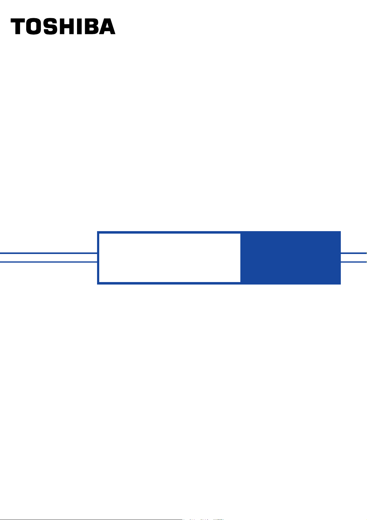
System Outline
Outdoor unit
Indoor unit
(Heating)
Suction gas
Discharge gas
Liquid
(Discharge gas / Suction gas / Liquid)
Energy saving
No.1 COP in heat recovery VRF industry.
DC twin rotary compressors are most congenial with R410A
and are used within the outdoor units. All compressors are
driven by a High-speed Calculation Vector Control Inverter.
3 pipe
FS unit
(Flow Selector unit)
Indoor unit
(Cooling)
Outdoor unit
High-speed Calculation
Vector Control Inverter
Average COP
8HP System
10HP System
Super-HRM(R410A)
3.83
3.45
DC Twin Rotary
Compressor
Simultaneous Operation
By control of the FS unit, Super HRM enables simultaneous operation of cooling and heating.
Super HRM also improves the energy efficiency by the recycling of exhaust heat.
Ex. Mainly Cooling, Partly Heating Operation
FS unit
Indoor unit
Heating
Cooling Cooling Cooling
Main Heat
Exchanger Sub-Heat
Exchanger
Outdoor unit
Compressor
5
Page 7
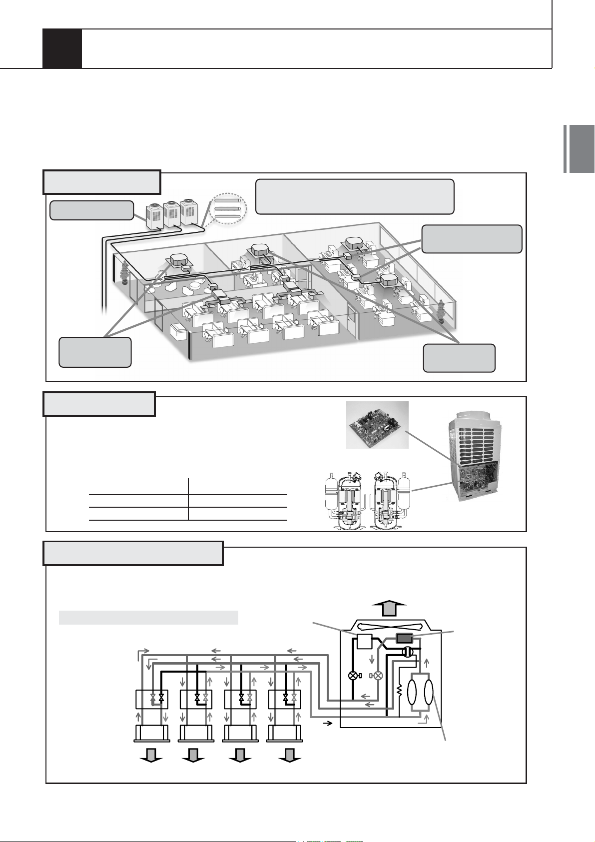
Design Flexibility
3
Piping flexibility
Equivalent piping length
Up to 125m
50m (from 1st branching)
35m (elevation between FCU)
50m (Elevation between CDU and FCU)
Elevation between indoor units = 35m(No.1!)
Furthest piping length from 1st branch
= 50m(No.1!)
Flexibile Joint Combination
Y Branch after header branch
(Toshiba unique technology)
Header branch after Y joint
Header after header branch
(Toshiba unique technology)
FS Unit Design
The compact and light weight design of the FS unit(Flow Selector Unit)allows it to be easily
installed within a limited space.
190H x 250W x 160D
5kg
Easy of hanging
(Only 2 hangers)
Easy maintenance
(Valve coil and P.C. board are
on the same side)
Centralized Control System
By using the central control devices, individual control of indoor units is possible throughout
multiple systems. Centralized control systems with Super MMS can also be integrated with Building Management System (BMS).
Super MMS Super HRM
Central remote
controller
6
Page 8

4
System overview
7
Page 9

8
Page 10
4
System overview
Foreword
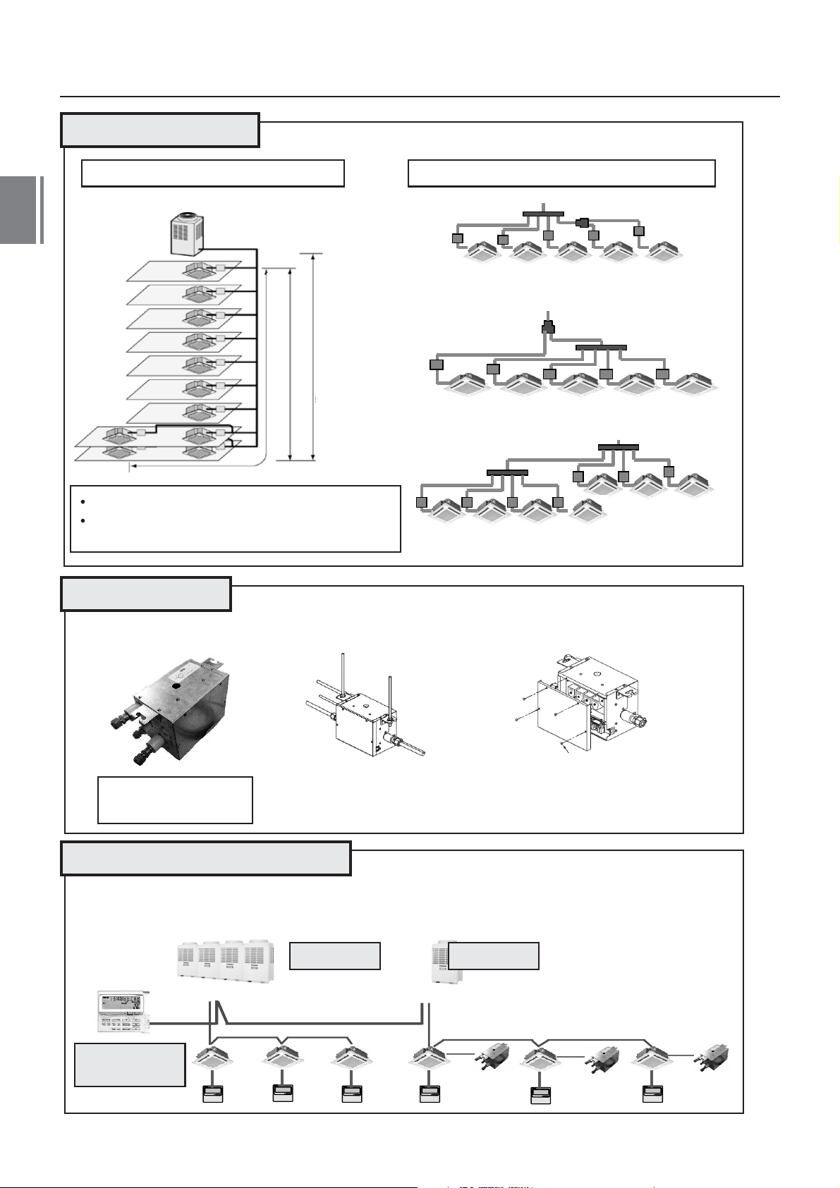
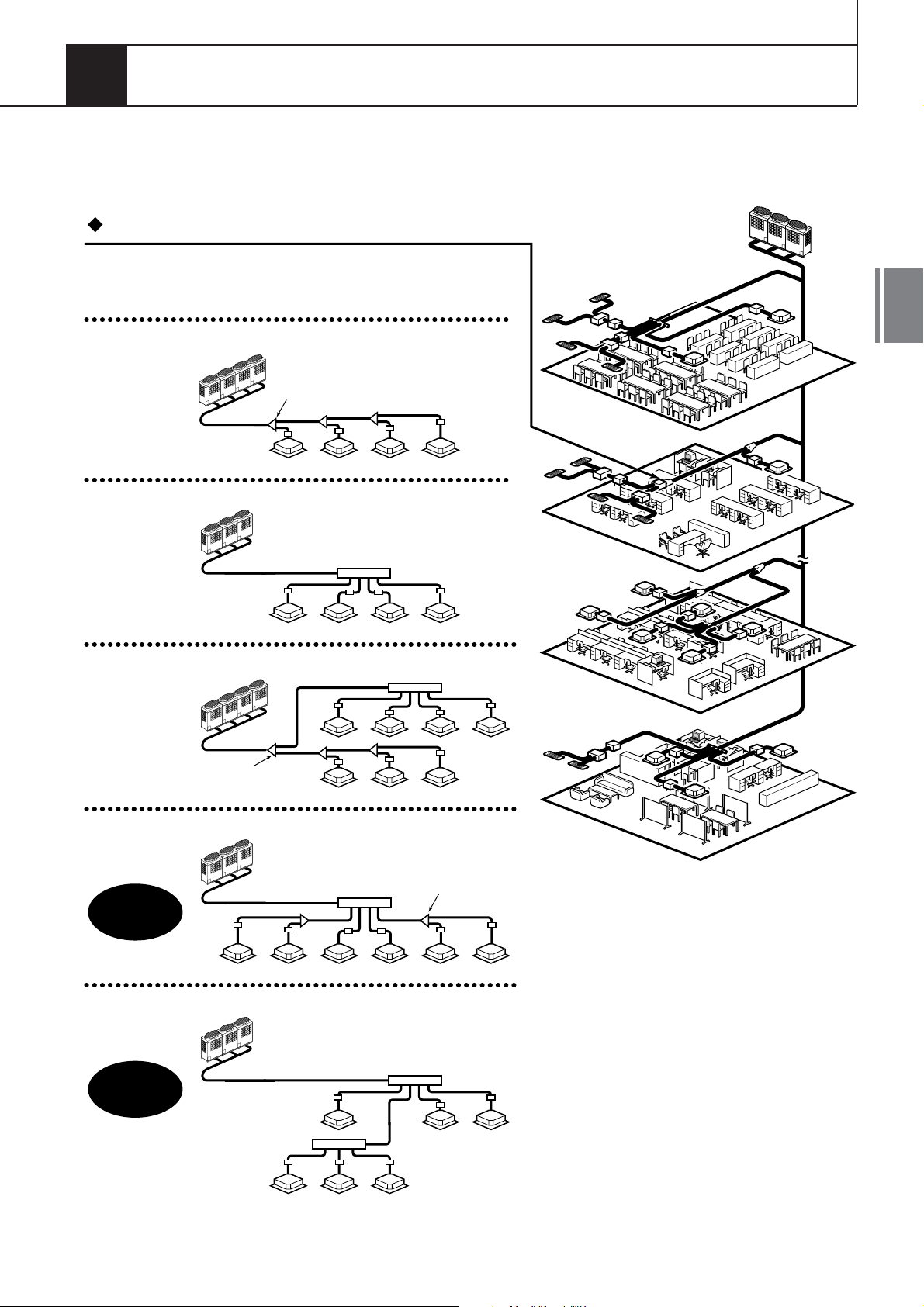
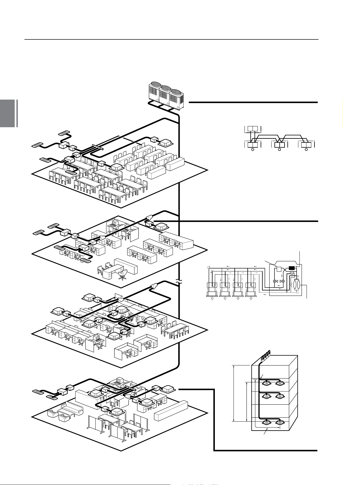
1. OUTLINE OF TOSHIBA SUPER HRM
(Super Heat Recovery Multi System)
Shortest route design by free branching
The Combination of line and header branching is highly flexible.
This follows for the shortest design route possible, thereby saving
on installation time and cost. Line/header branching after the
header branching is only available with TOSHIBA Super HRM.
Line branching
Outdoor unit
4
Branching joint
FS unit
Indoor unit
Header branching
Outdoor unit
Branching
header
FS unit
Indoor unit
Line + Header branching
Outdoor unit
Branching joint
Indoor
unit
Header
Line branching after header branching
Outdoor unit
8F
7F
2F
FS
unit
1F
Branching joint
Super HRM
MMS Only
Only
Indoor unit
Header
Header branching after header branching
Outdoor unit
Header
Super HRM
Only
Header
FS unit
Indoor unit
FS unit
9
Page 11
4
Non-polarized control wiring
between outdoor and indoor units
8F
7F
Outdoor unit
Indoor unit
FS unit
Indoor
unit
Heating Cooling Cooling Cooling
Simultaneous operation
U1 U2
U1 U2 U1 U2 U1 U2
main heat exchanger
Sub heat exchanger
Outdoor unit
Compressor
10
2F
1F
Outdoor
unit
Height difference between indoor
Height difference between indoor
unit and indoor unit : 35m
unit and outdoor unit : 50m
From 1st branching to the
furthest indoor unit : 50m
Allowable pipe length :
150m equivalent length
1st branching
section
Page 12

Energy saving
No.1 COP in heat recovery VRF industry.Compared with the conventional chiller fan coil system,
a large energy saving can be achieved.
Advanced bus communication system
Wiring between indoor and outdoor units is a simple 2 core wire system.
Communication of addresses is also automatically configured.
A default test mode operation is available.
Self diagnostics system
Comprehensive troubleshooting codes allows for a timely identification of possible problems arising.
High lift and flexible piping design
Equivalent pipe length of 150m and vertical lift of 50m is possible with TOSHIBA Super HRM.
Vertical lift between indoor units of 35m is the highest in the industry.
Also the maximum piping length from the 1st branch is 50m.
This allows for greater flexibility within the building design of the system.
Simultaneous operation
By controlling the FS unit, Super HRM enables simultaneous operation of cooling and heating.
This operation meets the various requirements of modern buildings that are highly airtight or have
an increasing heat load due to the use of computers. Super HRM also improves energy efficiency by
recycling of the exhaust heat.
Extended outdoor temperature operating range
By use of sophisticated system control with inverter driven compressors, the operating range
in cooling has been increased from -5
to -10 .
4
Compact FS unit design
The compact and light weight design of the FS unit (Flow selector unit) allows it to be easily
installed with in a limited space.
Group control by one FS unit
Up to 8 indoor units can be group controlled by the use of only one FS unit, this gives greater flexibility for
various different types and sizes of rooms.
Intelligent control
TOSHIBA Super HRM intelligent controls and modulating valves deliver the required capacity
according to the load variation from 50% to 100%.
The intelligent controls and modulating valves limit or increase the cooling capacity dynamically so
humidity and temperature are kept within the comfort zone.
Conforms to building control law
IAQ (Indoor Air Quality) is also achieved by combining various accessories required by the Building
Control Law.
Wide control applications
Artificial Intelligence Network system.
Central control and monitoring system available.
Weekly schedule operation through weekly timer.
Integration with Building Management System (BMS) is available.
11
Page 13
4
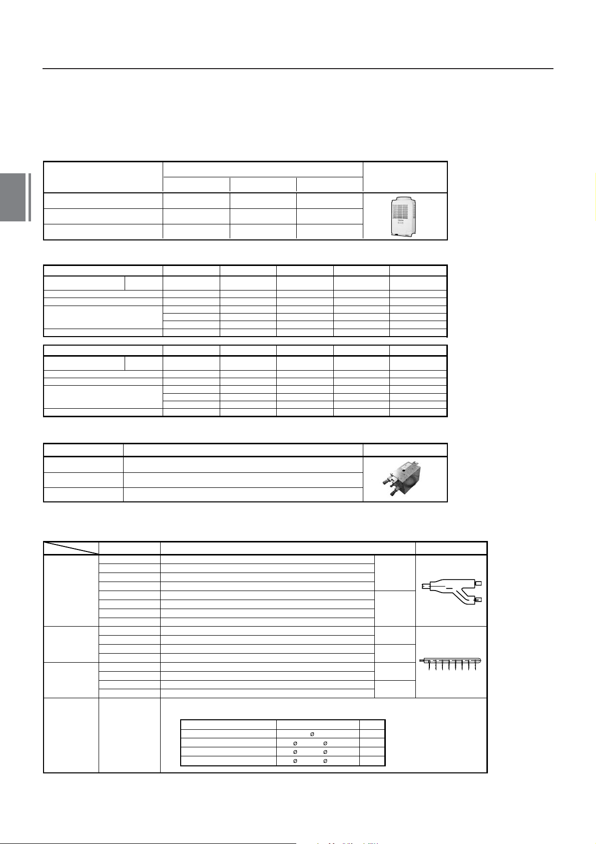
2. SUMMARY OF SYSTEM EQUIPMENTS
Equipment
1. Outdoor units
Corresponding HP
Model name MMY-
Cooling capacity (kW)
Heating capacity (kW)
8HP
MAP0802FT8
22.4
25.0
2. Outdoor units (Combination of outdoor units)
Corresponding HP
Combined model
Cooling capacity (kW)
Heating capacity (kW)
Combined outdoor units
No. of connectable indoor units
MMY-
8HP 10HP
MAP0802FT8
22.4
25
8HP
13
Inverter unit
10HP
MAP1002FT8
28.0
31.5
MAP1002FT8
28
31.5
10HP
16
MAP1202FT8
12HP
MAP1202FT8
33.5
35.5
12HP
16
12HP
33.5
35.5
16HP
AP1602FT8
45
50
8HP
8HP
27
Appearance
18HP
AP1802FT8
50.4
56.5
10HP
8HP
30
Corresponding HP
Combined model
Cooling capacity (kW)
Heating capacity (kW)
Combined outdoor units
No. of connectable indoor units
MMY-
20HP 24HP
AP2002FT8
56
63
10HP
10HP
33
AP2402FT8
68
76.5
8HP
8HP
8HP
40
26HP
AP2602FT8
73
81.5
10HP
8HP
8HP
43
3. FS units (Flow selector units)
Model name
RBM-Y1122FE
RBM-Y1802FE
RBM-Y2802FE
Total capacity for indoor unit : Below 11.2 kw
Total capacity for indoor unit : 11.2 to below 18.0 kw
Total capacity for indoor unit : 18.0 to 28.0 kw or less
*Accessory part (Sold separately): Connection cable kit (RBC-CBK15FE) up to 15m.
Usage Appearance
4. Branching joints and headers
Model name Usage
Y-shape
branching
joint (*3)
4-branching
header (*4) (*5)
8-branching
header (*4) (*5)
T-shape
branching
joint (For
connection
of outdoor
units)
RBM-BY53FE
RBM-BY103FE
RBM-BY203FE
RBM-BY303FE
RBM-BY53E
RBM-BY103E
RBM-BY203E
RBM-BY303E
RBM-HY1043FE
RBM-HY2043FE
RBM-HY1043E
RBM-HY2043E
RBM-HY1083FE
RBM-HY2083FE
RBM-HY1083E
RBM-HY2083E
RBM-BT13FE
Indoor unit capacity code (*1) : Total below 6.4
Indoor unit capacity code (*1) : Total 6.4 or more and below 14.2
Indoor unit capacity code (*1) : Total 14.2 or more and below 25.2
Indoor unit capacity code (*1) : Total 25.2 or more
Indoor unit capacity code (*1) : Total below 6.4
Indoor unit capacity code (*1) : Total 6.4 or more and below 14.2
Indoor unit capacity code (*1) : Total 14.2 or more and below 25.2
Indoor unit capacity code (*1) : Total 25.2 or more
Indoor unit capacity code (*1) : Total below 14.2
Indoor unit capacity code (*1) : Total 14.2 or more and below 25.2
Indoor unit capacity code (*1) : Total below 14.2
Indoor unit capacity code (*1) : Total 14.2 or more and below 25.2
Indoor unit capacity code (*1) : Total below 14.2
Indoor unit capacity code (*1) : Total 14.2 or more and below 25.2
Indoor unit capacity code (*1) : Total below 14.2
Indoor unit capacity code (*1) : Total 14.2 or more and below 25.2
1 set 4 types T-shape joint pipes as described below:
The required quantity is arranged and they are combined on site.
Connection piping
Balance pipe
Piping at liquid side
Piping at discharge gas side
Piping at suction gas side
Corresponded dia. (mm)
9.5
12.7 to 22.2
19.1 to 28.6
22.2 to 38.1
28HP
AP2802FT8
78.5
88
10HP
10HP
8HP
47
Q'ty
1
1
1
1
AP3002FT8
For 3
piping
For 2
piping (*6)
For 3
piping
For 2
piping (*6)
For 3
piping
For 2
piping (*6)
30HP
84
95
10HP
10HP
10HP
48
Appearance
*1 ``Capacity code`` can be obtained from page 8. (Capacity code is not actual capacity)
*2 If total capacity code value of indoor unit exceeds that of outdoor unit, apply capacity code of outdoor unit.
*3 When using Y-shape branching joint for 1st branching, select according to the capacity code of outdoor unit.
*4 Max. capacity code of 6.0 in total can be connected.
*5 If capacity code of outdoor unit is 26 or more, it is not used for the 1st branching.
*6 This is used for branching to ``cooling only`` indoor unit.
*7 Model names for outdoor and indoor units described in this guide are shortened because of the space constraint.
12
Page 14
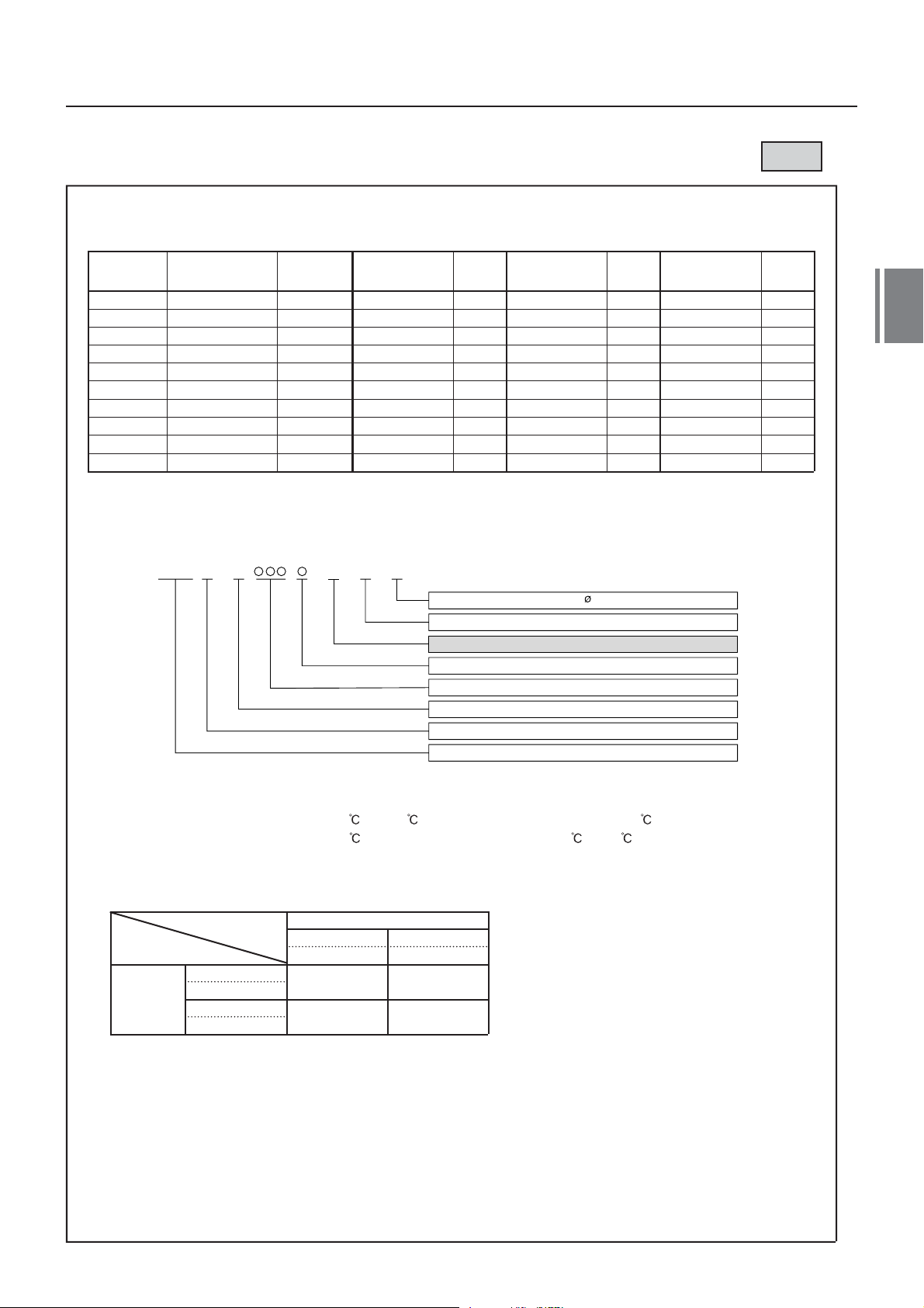
Super Heat Recovery Multi System Outdoor Unit
50Hz
HP (Capacity
code)
8HP ( 8)
10HP (10)
12HP (12)
16HP (16)
18HP (18)
20HP (20)
24HP (24)
26HP (26)
28HP (28)
30HP (30)
*
Model name
MMY-
MAP0802HT8
MAP1002HT8
MAP1202HT8
No. of
combined
units
1
1
1
2
2
2
12HP unit is for stand-alone use only.
Inverter
8 HP
MMY-
MAP0802FT8
MAP0802FT8
MAP0802FT8
MAP0802FT8
MAP0802FT8
MAP0802FT8
Outdoor unit combination with a 12HP unit is not available.
1. Allocation standard of model name
MMY- M AP T 8F
Used
Qty
1
2
1
3
2
1
Power supply specifications, 3 380-415 V, 50Hz ....... 8
T : Capacity variable unit
F : Heat recovery
Development series No.
Capacity rank HP x 10
New refrigerant R410A
M : Single module unit, No mark : Combined Model name
Modular Multi
Inverter
10 HP
MMY-
MAP1002FT8
MAP1002FT8
MAP1002FT8
MAP1002FT8
MAP1002FT8
MAP1002FT8
Used
Qty
1
1
2
1
2
3
Inverter
12 HP
MMY-
MAP1202FT8*
Used
Qty
1
4
2. Rated conditions (Rated mode : Condition)
Cooling : Indoor air temperature 27 DB/19 WB, Outdoor air temperature 35 DB
Heating : Indoor air temperature 20
DB, Outdoor air temperature 7 DB/6 WB
3. Compatibility with 1 Series
Oudoor unit MMY-
1 Series
-MAP**1FT8
FS unit
1 Series
RBM-Y***1E
2 Series
RBM-Y***2E
OK
OK
* 2 series outdoor units cannot be used with 1 series outdoor units.
2 Series*
-MAP**2FT8
NG
OK
13
Page 15
4
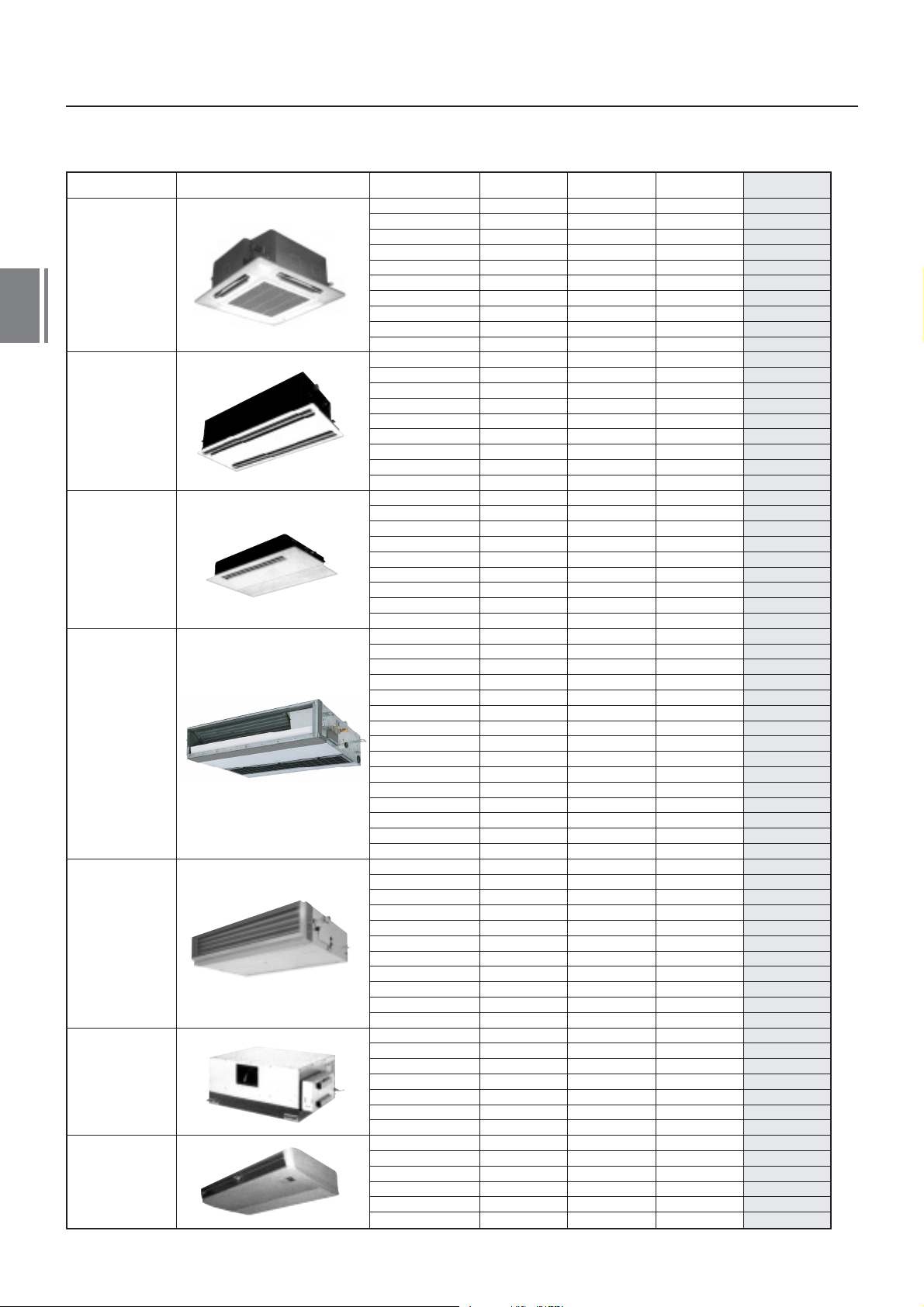
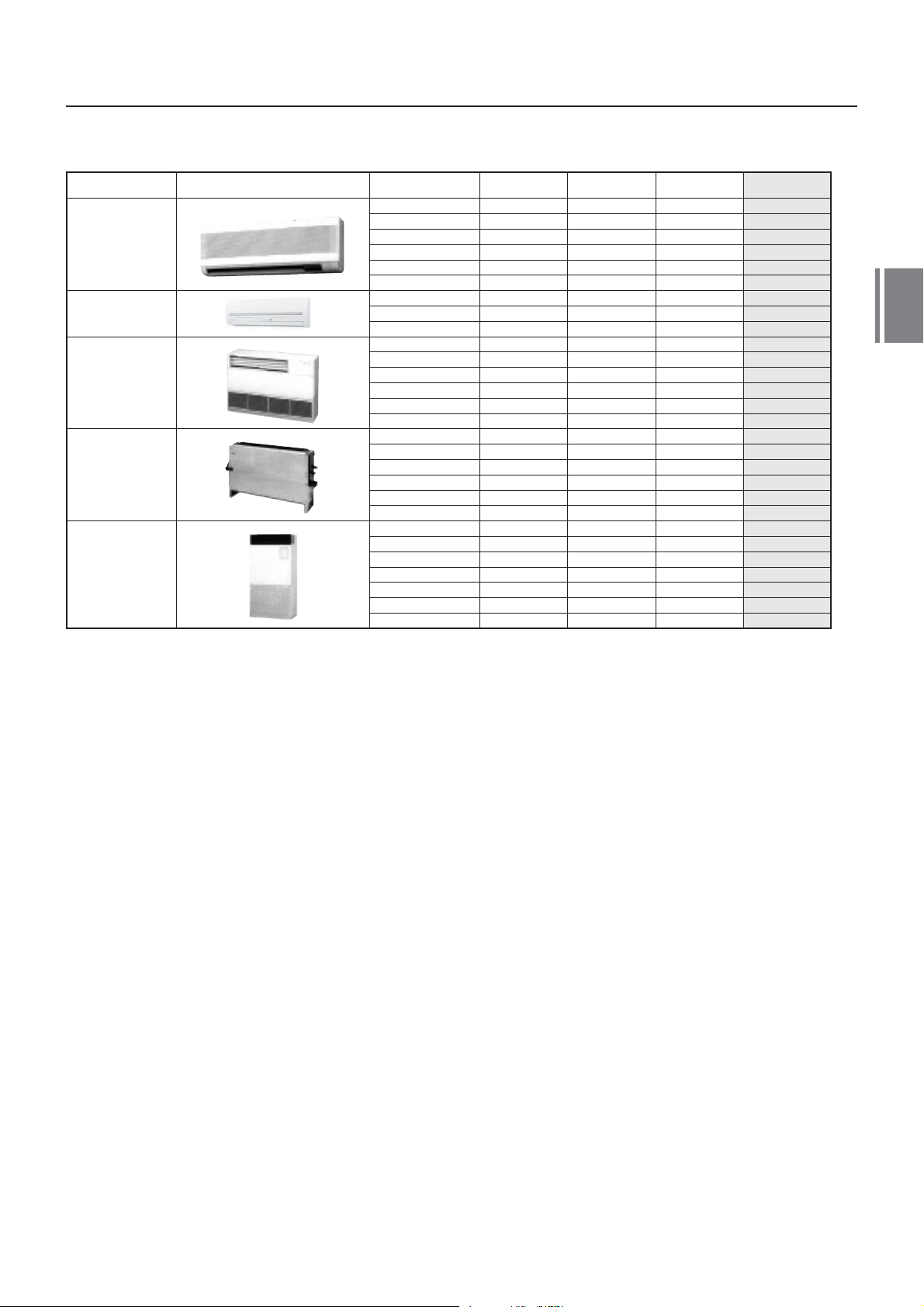
4. Indoor unit
*1) China market only *2) European market only *3) Korea market only
Type Appearance Model name Capacity rank Capacity code
009 type
012 type
015 type
018 type
024 type
027 type
030 type
036 type
048 type
056 type
007 type
009 type
012 type
015 type
018 type
024 type
027 type
030 type
1)
048 type
007 type
009 type
012 type
015 type
018 type
024 type
015 type
018 type
024 type
007 type
009 type
012 type
015 type
018 type
1)
007 type
*
1)
009 type
*
1)
012 type
*
1)
015 type
*
1)
018 type
*
007 type
009 type
012 type
015 type
018 type
007 type
009 type
012 type
015 type
018 type
024 type
027 type
030 type
036 type
048 type
056 type
018 type
024 type
027 type
036 type
048 type
072 type
096 type
015 type
018 type
024 type
027 type
036 type
048 type
4-way Air Discharge
Cassette Type
2-way Air Discharge
Cassette Type
1-way Air Discharge
Cassette Type
Slim Duct Type
Concealed Duct
Standard Type
Concealed Duct
High Static
Pressure Type
Under Ceilling Type
MMU-AP0091H
MMU-AP0121H
MMU-AP0151H
MMU-AP0181H
MMU-AP0241H
MMU-AP0271H
MMU-AP0301H
MMU-AP0361H
MMU-AP0481H
MMU-AP0561H
MMU-AP0071WH
MMU-AP0091WH
MMU-AP0121WH
MMU-AP0151WH
MMU-AP0181WH
MMU-AP0241WH
MMU-AP0271WH
MMU-AP0301WH
MMU-AP0481WH*
MMU-AP0071YH
MMU-AP0091YH
MMU-AP0121YH
MMU-AP0151SH
MMU-AP0181SH
MMU-AP0241SH
MMU-AP0152SH
MMU-AP0182SH
MMU-AP0242SH
MMD-AP0071SPH
MMD-AP0091SPH
MMD-AP0121SPH
MMD-AP0151SPH
MMD-AP0181SPH
MMD-AP0071SPH(SH)-C
MMD-AP0091SPH(SH)-C
MMD-AP0121SPH(SH)-C
MMD-AP0151SPH(SH)-C
MMD-AP0181SPH(SH)-C
MMD-AP0071SPH-K
MMD-AP0091SPH-K
MMD-AP0121SPH-K
MMD-AP0151SPH-K
MMD-AP0181SPH-K
3)
*
3)
*
3)
*
3)
*
3)
*
MMD-AP0071BH
MMD-AP0091BH
MMD-AP0121BH
MMD-AP0151BH
MMD-AP0181BH
MMD-AP0241BH
MMD-AP0271BH
MMD-AP0301BH
MMD-AP0361BH
MMD-AP0481BH
MMD-AP0561BH
MMD-AP0181H
MMD-AP0241H
MMD-AP0271H
MMD-AP0361H
MMD-AP0481H
MMD-AP0721H
MMD-AP0961H
MMC-AP0151H
MMC-AP0181H
MMC-AP0241H
MMC-AP0271H
MMC-AP0361H
MMC-AP0481H
1.00
1.25
1.70
2.00
2.50
3.00
3.20
4.00
5.00
6.00
0.8
1.00
1.25
1.70
2.00
2.50
3.00
3.20
5.00
0.80
1.00
1.25
1.70
2.00
2.50
1.70
2.00
2.50
0.80
1.00
1.25
1.70
2.00
0.80
1.00
1.25
1.70
2.00
0.80
1.00
1.25
1.70
2.00
0.80
1.00
1.25
1.70
2.00
2.50
3.00
3.20
4.00
5.00
6.00
2.00
2.50
3.00
4.00
5.00
8.00
10.00
1.70
2.00
2.50
3.00
4.00
5.00
Cooling
capacity (kW)
2.8
3.6
4.5
5.6
7.1
8.0
9.0
11.2
14.0
16.0
2.2
2.8
3.6
4.5
5.6
7.1
8.0
9.0
14.0
2.2
2.8
3.6
4.5
5.6
7.1
4.5
5.6
7.1
2.2
2.8
3.6
4.5
5.6
2.2
2.8
3.6
4.5
5.6
2.2
2.8
3.6
4.5
5.6
2.2
2.8
3.6
4.5
5.6
7.1
8.0
9.0
11.2
14.0
16.0
5.6
7.1
8.0
11.2
14.0
22.4
28.0
4.5
5.6
7.1
8.0
11.2
14.0
Heating
capacity (kW)
3.2
4.0
5.0
6.3
8.0
9.0
10.0
12.5
16.0
18.0
2.5
3.2
4.0
5.0
6.3
8.0
9.0
10.0
16.0
2.5
3.2
4.0
5.0
6.3
8.0
5.0
6.3
8.0
2.5
3.2
4.0
5.0
6.3
2.5
3.2
4.0
5.0
6.3
2.5
3.2
4.0
5.0
6.3
2.5
3.2
4.0
5.0
6.3
8.0
9.0
10.0
12.5
16.0
18.0
6.3
8.0
9.0
10.0
16.0
25.0
31.5
5.0
6.3
8.0
9.0
12.5
16.0
14
Page 16
4. Indoor unit
*1) China market only *2) European market only
Type Appearance Model name Capacity rank Capacity code
007 type
009 type
012 type
015 type
018 type
024 type
007 type
009 type
012 type
007 type
009 type
012 type
015 type
018 type
024 type
007 type
009 type
012 type
015 type
018 type
024 type
015 type
018 type
024 type
027 type
036 type
048 type
056 type
High Wall Type
(1 series)
High Wall Type
(2 series)
Floor Standing
Cabinet Type
Floor Standind
Concealed Type
Floor Standind Type
MMK-AP0071H
MMK-AP0091H
MMK-AP0121H
MMK-AP0151H
MMK-AP0181H
MMK-AP0241H
MMK-AP0072H*
MMK-AP0092H*
MMK-AP0122H*
MML-AP0071H
MML-AP0091H
MML-AP0121H
MML-AP0151H
MML-AP0181H
MML-AP0241H
MML-AP0071H
MML-AP0091H
MML-AP0121H
MML-AP0151H
MML-AP0181H
MML-AP0241H
MMF-AP0151H
MMF-AP0181H
MMF-AP0241H
MMF-AP0271H
MMF-AP0361H
MMF-AP0481H
MMF-AP0561H
2)
2)
2)
0.80
1.00
1.25
1.70
2.00
2.50
0.80
1.00
1.25
0.80
1.00
1.25
1.70
2.00
2.50
0.80
1.00
1.25
1.70
2.00
2.50
1.70
2.00
2.50
3.00
4.00
5.00
6.00
*3) Korea market only
Cooling
capacity (kW)
2.2
2.8
3.6
4.5
5.6
7.1
2.2
2.8
3.6
2.2
2.8
3.6
4.5
5.6
7.1
2.2
2.8
3.6
4.5
5.6
7.1
4.5
5.6
7.1
8.0
11.2
14.0
16.0
Heating
capacity (kW)
2.5
3.2
4.0
5.0
6.3
8.0
2.5
3.2
4.0
2.5
3.2
4.0
5.0
6.3
8.0
2.5
3.2
4.0
5.0
6.3
8.0
5.0
6.3
8.0
9.0
10.0
16.0
18.0
4
15
Page 17
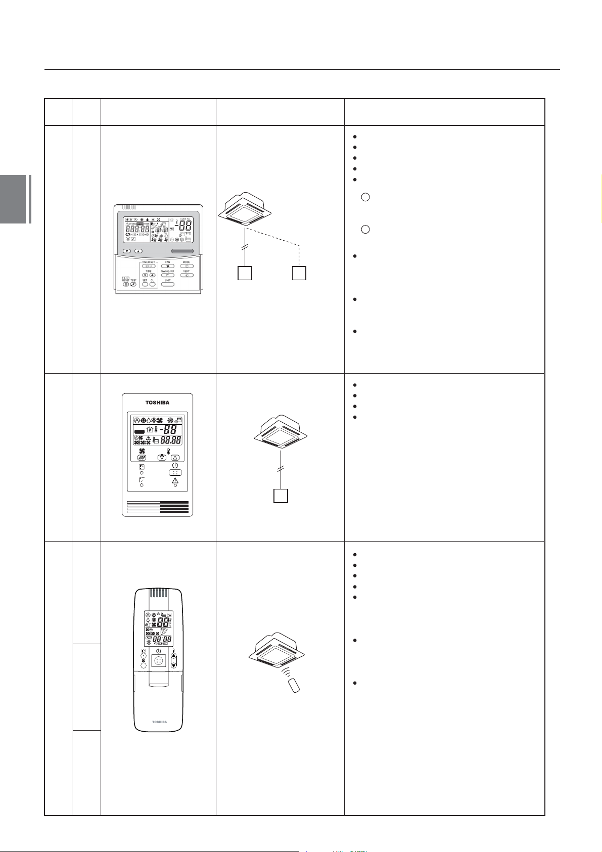
5. Remote controller
4
Name
Model
name
Appearance Application Function
SET DATA
UNIT No.
SETTING
R.C. No.
TEST
CL
SET
Wired remote controllerSimple wired remote controllerWireless remote controller kit
TEST
SETTING
UNIT
ûC
ûF
CODE No.
Connected to indoor unit
Wired remote
controller
Wired remote controller
(In case of control by
2 remote controllers)
Connected to indoor unit
Start / Stop
Mode Change
Temperature setting
Change of air flow
Timer function
1
On or off timer operation, setting in 30 minute
increments.
Automatic Off function.
Combined with the weekly timer, weekly
2
schedule operation can be operated.
Filter sign
Displays automatically maintenance time of
indoor filter.
Filter sign flashes.
Self-diagnosis function
Pressing ``CHECK`` button displays cause of
fault on the check code.
Control by 2 remote controllers is available.
Two remote controllers can be connected to
one indoor unit. The indoor unit can be
separately operated from a different location.
Start / Stop
Temperature setting
Change of air flow
Check code display
RBC-AS21E/RBC-AS21E2 RBC-AMT21E/RBC-AMT31E
TCB-AX21U(W)-E
TCB-AX21U(W)-E2
RBC-AX22CE
RBC-AX22CE2
Simple remote controller
Connected to indoor unit
Start / Stop
Mode change
Temperature setting
Change of air flow
Timer function
On or off timer operation, setting in 30 minute
increments.
Automatic Off function.
Control by 2 remote controllers is available.
Two wireless remote controllers can operate
one indoor unit. The indoor unit can be
separately operated from a different location.
Check code display
TCB-AX21U(W)-E2
(for 4-way airdischarge cassette)
RBC-AX22CE2
(for under ceiling)
TCB-AX21-E2
(for other units except for the concealed duct
high static pressure)
16-1
16
TCB-AX21E
TCB-AX21E2
Page 18
Name
Model
name
Appearance Application Performance
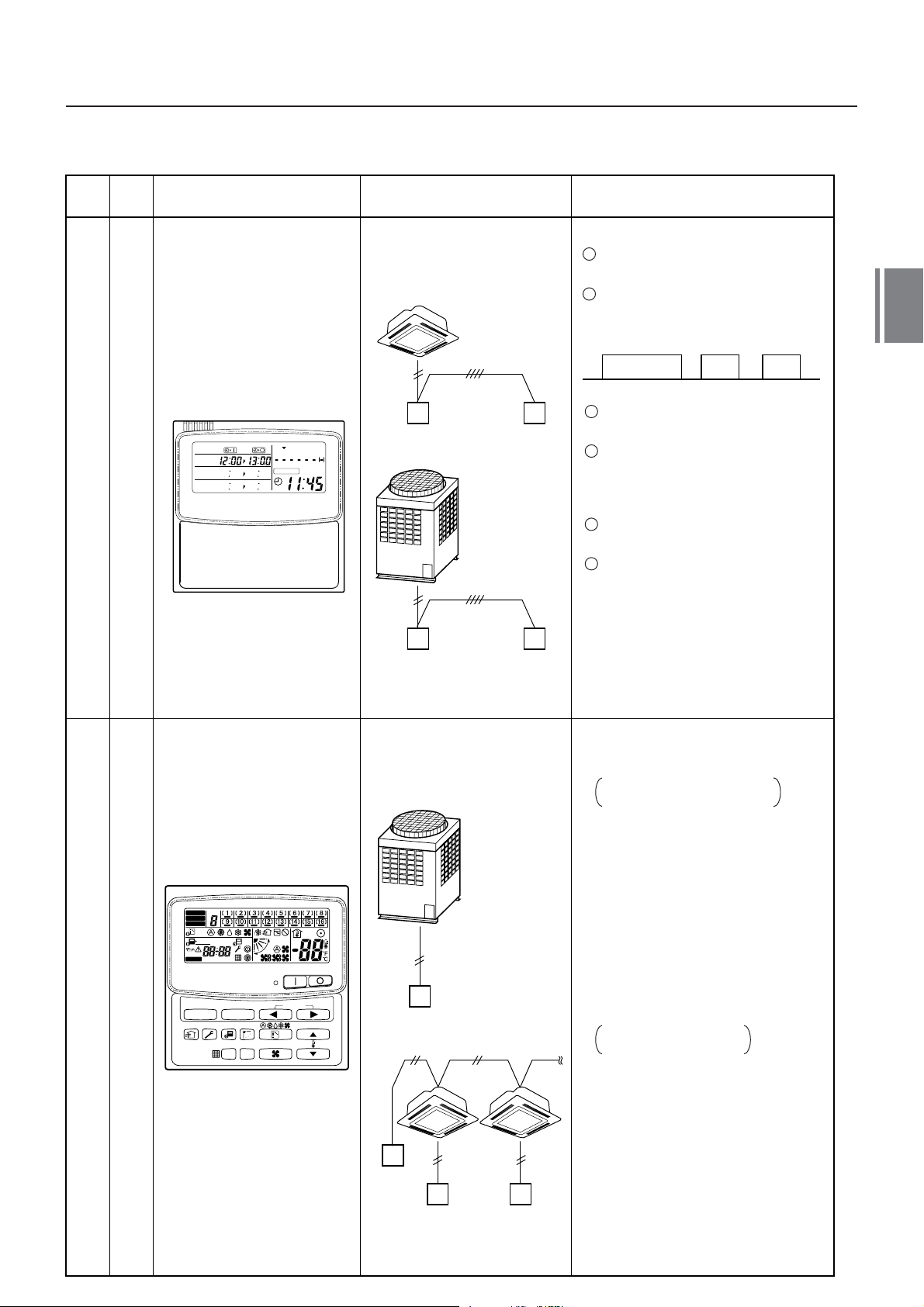
Weekly timer
RBC-EXW21E
RBC-EXW21E2
PROGRAM1
PROGRAM2
PROGRAM3
WEEKLY TIMER
SuMoTuWeTh FrSa
ERROR
Connected to central
remote controller or
wired remote controller
Wired
remote controller
Outdoor unit
Central
remote controller
Weekly
timer
Weekly
timer
Weekly schedule operation
1
Setting different start / stop time for each
day of the week
2
ON / OFF can be set 3 times
a day.
ON
8:00 12:00 13:00 18:00 19:00 21:00
3
``CHECK`` ``PROGRAM`` ``DAY``
OFF ON OFF ON OFF
button copying of settings easy.
4
Two different schedules for a
week can be specified.
(Summer schedule and winter
schedule, etc.)
5
``CANCEL`` ``DAY`` button enables
holiday setting.
6
If power supply fails, the setting
contents are stored in the memory for
100 hours.
4
ZONE
ALL
ZONE
GROUP
1234
SET DATA
SETTING
SELECT ZONE
TCB-SC642TLE
TCB-SC642TLE2
TEST
UNIT No.
R.C.
No.
SET
CL
Central remote controller
GROUP
CODE
No.
Connected to outdoor unit,
indoor unit
Outdoor
unit
Central
remote controller
Central
remote
controller
Indoor
remote controller
Individual control up to 64 indoor units.
Individual control for max. 64 indoor
units divided into 4 zones.
Up to 16 indoor units for each
zone
Up to 16 outdoor header units are
connectable.
Four selectable central control settings to
restrict individual remote controller
operations.
Setting for one of 1 to 4 zones is
available.
Can be used with other central control
devices (Up to 10 central control
devices with in one control circuit)
Two selectable control modes
Central controller mode
Remote controller mode
Setting of simultaneous ON/OFF 3
times for each day of the week
combined with a weekly timer.
16-2
17
Page 19
Name
Model
name
Appearance Application Performance
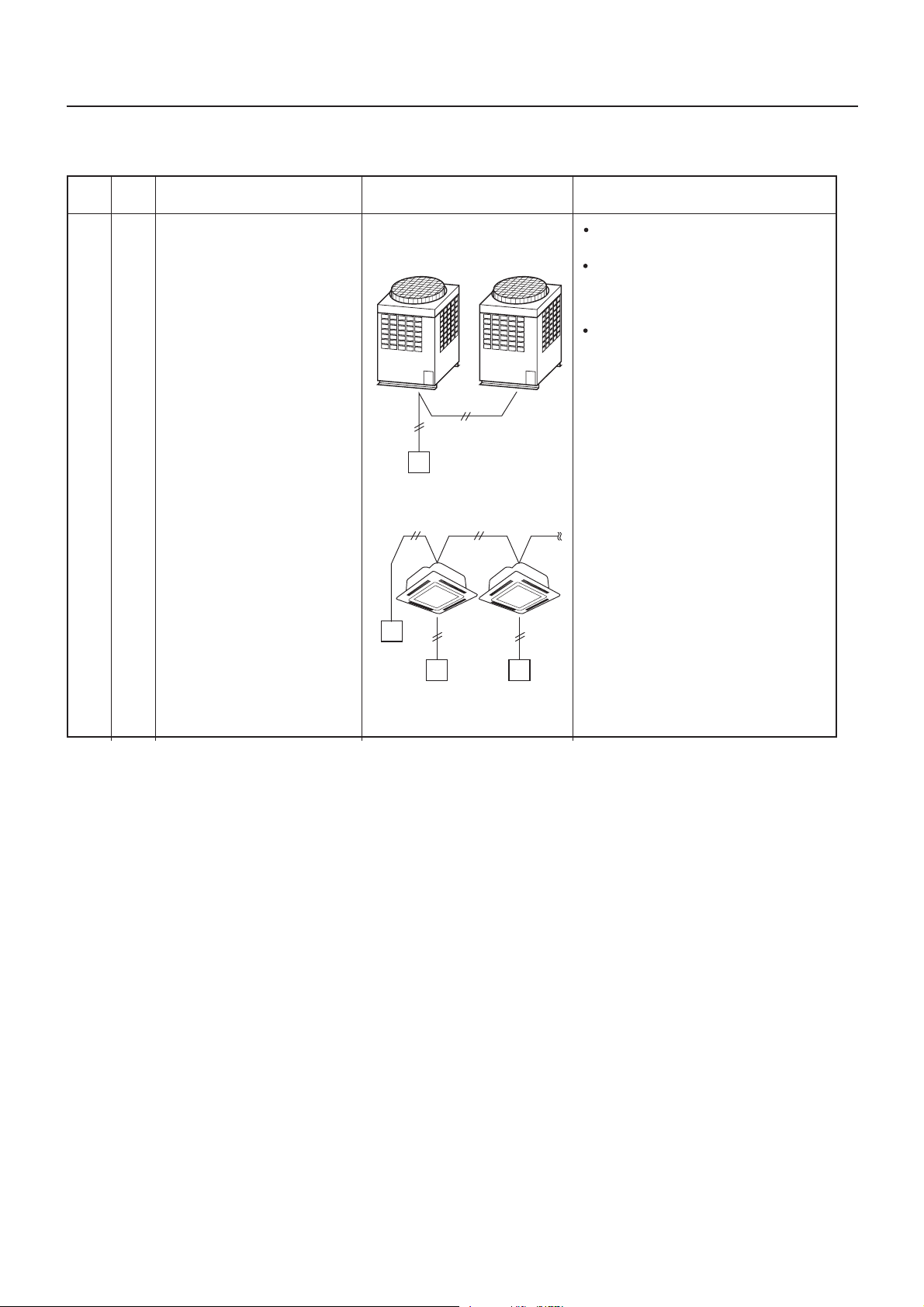
TCB-CC163TLE2
ON-OFF controller
Connected to outdoor unit,
indoor unit
Header
ON-OFF
controller
ON-OFF
controller
Outdoor unit
remote controller
Follower
Outdoor unit
Indoor
Individual control up to 16 indoor units.
Setting of simultaneous ON-OFF 3
times for each day of the week when
combined with a weekly timer.
Connected to 2 remote controllers is
possible.
16-3
18
Page 20

5
Capacity compensation chart
17
Page 21

18
Page 22
5
Capacity compensation chart
Foreword
Cooling/heating capacity characteristics
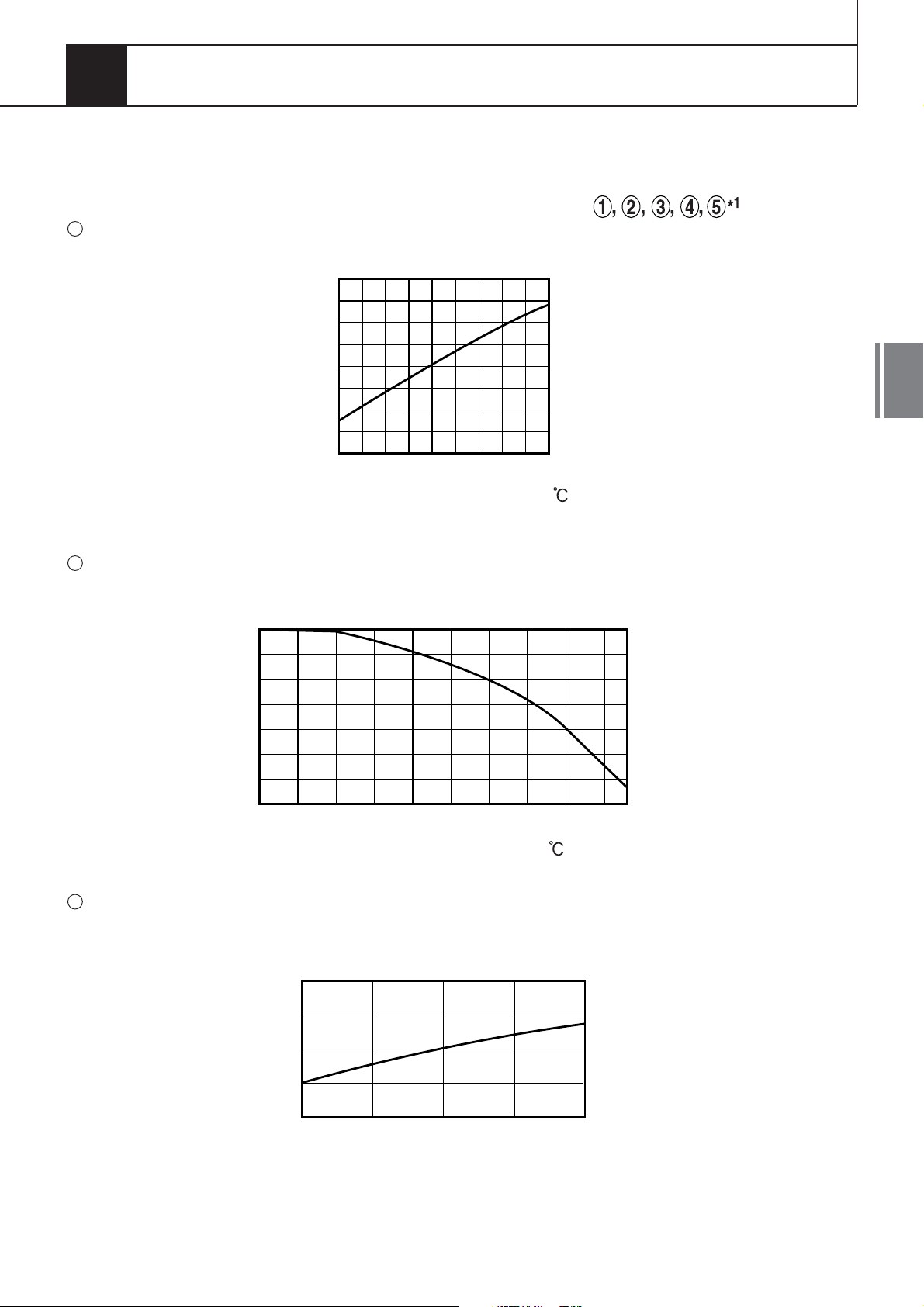
1. Cooling capacity calculation method :
Required cooling capacity = Cooling capacity x Factor ( ) kW
1
Indoor air wet bulb temperature vs. capacity correction value
1.2
1.1
1.0
0.9
5
0.8
15
Capacity correction value
20 24
Indoor air wet bulb temp. ( )
2
Outdoor air dry bulb temperature vs.capacity correction value
1.2
1.1
1.0
0.9
-
50 5 1015202530354043
Capacity correction value
Outdoor air dry bulb temp. ( )
3
Air flow variation ratio of indoor unit vs. capacity correction (For concealed duct type only)
1.1
1.0
0.9
80 90 100 110 120
Capacity correction value
1: Coefficient to use for the correction of the outdoor unit capacity when the total capacity of
*
Air flow variation ratio (%)
the indoor units are not equal to the outdoor unit capacity.
19
Page 23
5
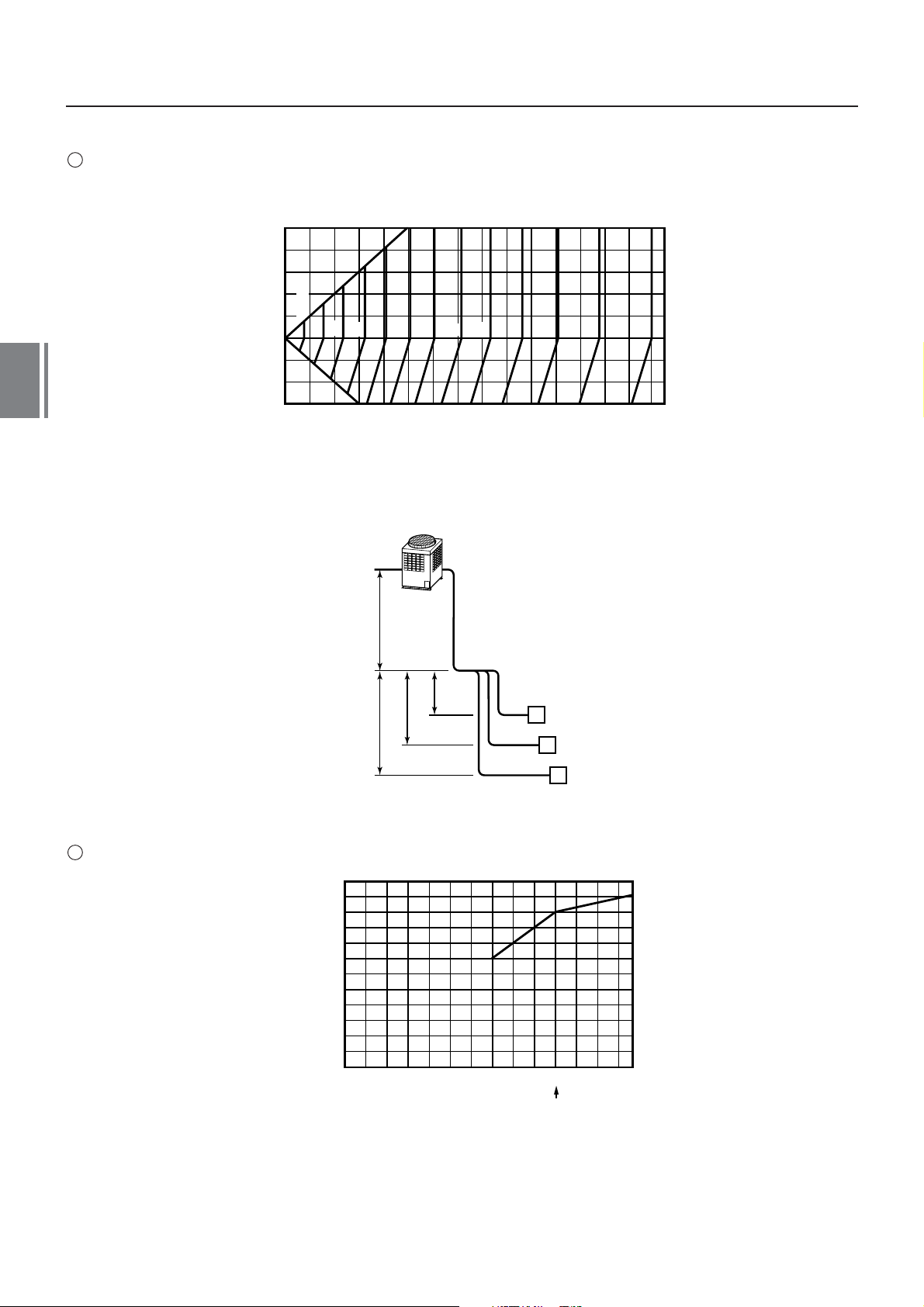
4
Connecting pipe length and lift difference between indoor and outdoor units vs. capacity correction value
Outdoor unit (8 to 30HP)
50
40
30
20
%100
10
0
-
10
-
20
-
30
Height of outdoor unit H (m)
98
20 30 40 50 60 70 80 90
100
Pipe length (Equivalent length) L (m)
96
94
92
908488
ho l
86
Outdoor unit
,
L
is the longest one of
,
(l
,
o
H = ho +
(Largest one of ha, hb, and hc)
82
80
78
100 110 120 130 140 150
o + l,a, l,o + l,b, l,o + l,c)
76
5
Correction of outdoor unit diversity
hb
hc
120
100
80
60
40
Correction (%)
20
20 40 60 80 100 120 135
0
ha
,
a
l
A
,
b
l
B
,
l
c
C
Standard capacity ratio
Indoor units total capacity ratio (%)
Indoor unit
1: Coefficient to use for the correction of the outdoor unit capacity when the total capacity of
*
the indoor units are not equal to the outdoor unit capacity.
20
Page 24
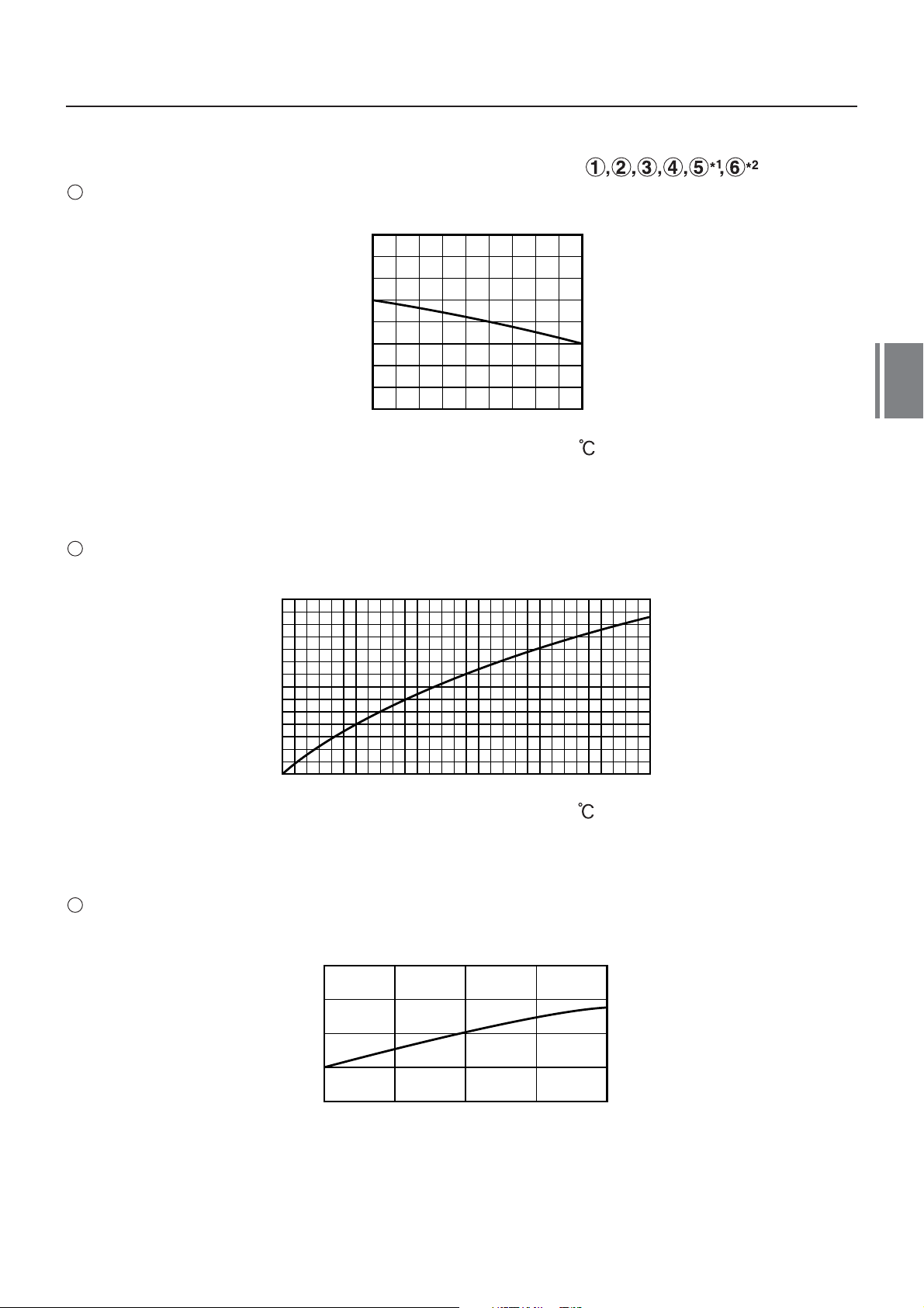
2. Heating capacity calculation method :
Required heating capacity = Heating capacity x Factor ( ) kW
1
Indoor air dry bulb temperature vs. capacity correction value
1.2
1.1
1.0
0.9
0.8
15 20 24
Capacity correction value
Indoor air dry bulb temp. ( )
2
Outdoor air wet bulb temperature vs. capacity correction value
5
1.2
1.1
1.0
0.9
0.8
0.7
0.6
0.5
-
15
Capacity correction value
3
Air flow variation ratio of indoor unit vs. capacity correction (For concealed duct type only)
-
10
-
50 5 1015
Outdoor air wet bulb temp. (
)
1.1
1.0
0.9
80 90 100 110 120
Capacity correction value
1: Coefficient to use for the correction of the outdoor unit capacity when the total capacity of
*
Air flow variation ratio (%)
the indoor units are not equal to the outdoor unit capacity.
2: Refer to item 3 on the next page.
*
21
Page 25
0
80
60
40
20
20 40 60 80 100 120 135
120
100
Outdoor unit
Indoor unit
L, is the longest one of
(l,o + l,a, l,o + l,b, l,o + l,c)
H = ho +
(Largest one of ha, hb, and hc)
A
ha
hb
hc
ho l,o
l,a
l,b
l,c
B
C
100 2030405060708090
100 110 120 130 140 150
-
20
-
10
0
10
20
30
40
50
-
30
100%
92
93
94
96
97
98
99
91
95
5
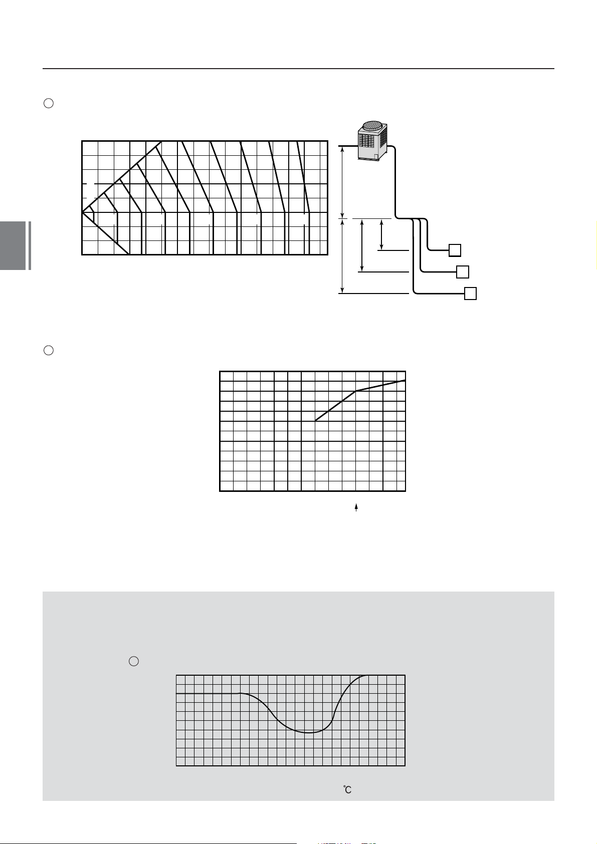
4
Connecting pipe length and lift difference between indoor and outdoor units vs. capacity correction value
Outdoor unit (8 to 30HP)
Height of outdoor unit H (m)
Pipe length (Equivalent length) L (m)
5
Correction of outdoor unit diversity
*
the indoor units are not equal to the outdoor unit capacity.
1: Coefficient to use for the correction of the outdoor unit capacity when the total capacity of
Correction (%)
Indoor units total capacity ratio (%)
Standard capacity ratio
3. Capacity correction in case of frost on the outdoor heat exchanger when in heating
Correct the heating capacity when frost can be found on the outdoor heat exchanger.
Heating capacity =Capacity after correction of outdoor unit Correction value of capacity resulted from frost
(Capacity after correction of outdoor unit : Heating capacity calculated in the above item 2.)
22
6
Capacity correction in case of frost on the outdoor heat exchanger
1.0
0.9
0.8
Capacity correction value
-
15
-
10
Outdoor air wet bulb temp. (
-
50 5 10
)
Page 26
4. Capacity calculation for each indoor unit
Capacity for each indoor unit
= Capacity after correction of outdoor unit x
Required standard capacity of indoor unit
Total value of standard indoor unit capacity
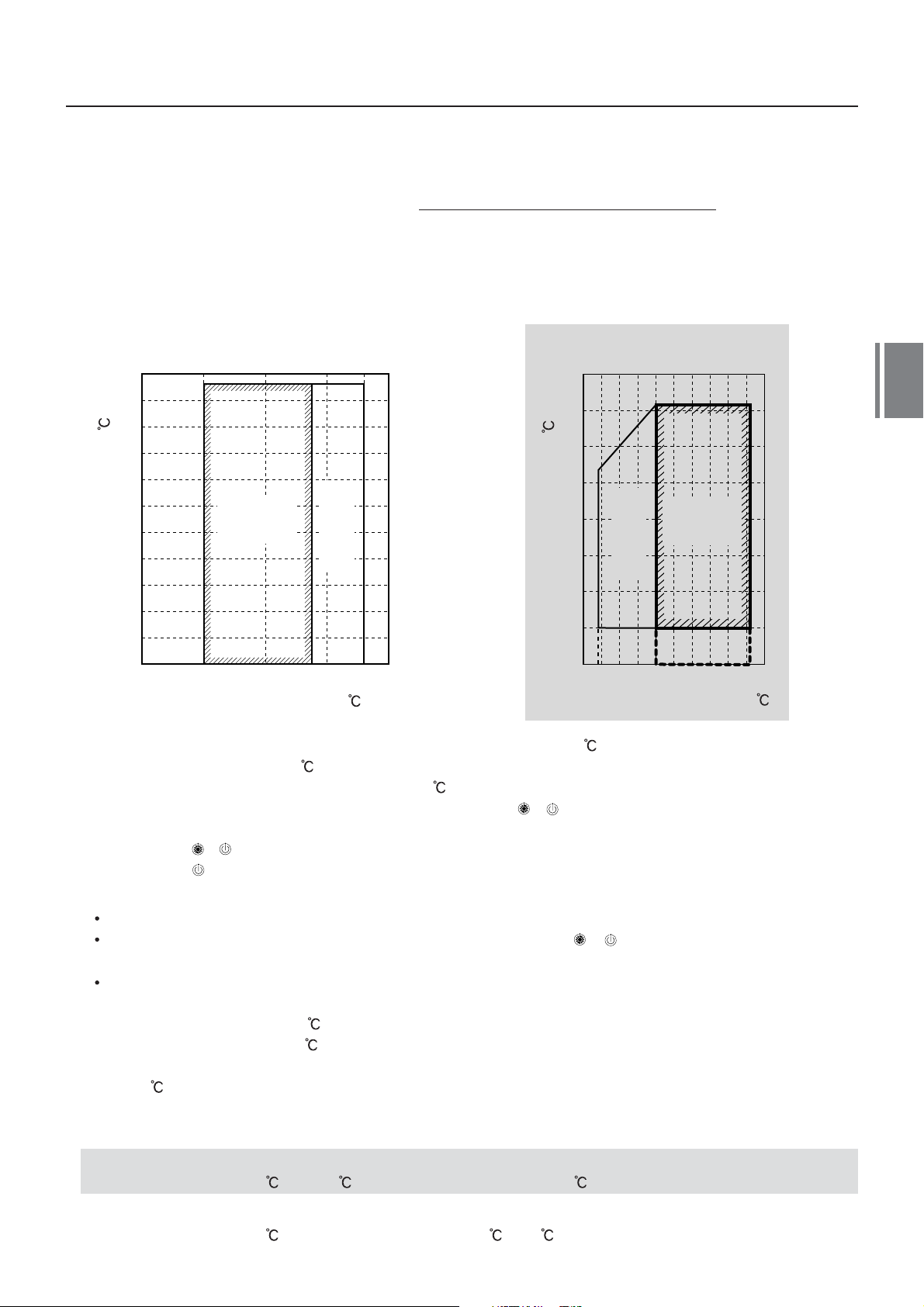
5. Operating temperature range
In cooling time
45
40
35
30
25
20
15
10
5
0
Outdoor air dry bulb temp. ( )
-
5
-
10
Continuously
operable
range
Usable range
(in pull down)
3025 28201510
Indoor air wet bulb temp. ( )
)
-
Outdoor air wet bulb temp. (
-
-
In heating time
20
15
10
5
0
-
5
10
15
20
5 1015202530
Indoor air dry bulb temp. ( )
Continuously
operable
Usable range
(in warming-up)
range
* The unit can be operated even if the outdoor temperature goes below -20 , however you must note that the war ranty only covers down to -15
* When outdoor air temperature falls to below -15
* When outdoor temperature goes out of the specified range
this is because operation beyond this temperature is outside of specification.
, it may shorten the lifespan of the product.
`` or `` mark is indicated on the remote control-
ler display and the required operation will stop.
`` & `` : When heating operation
`` `` : When cooling operation
5
[Notice]
This indication is not a failure.
When outdoor temperature goes back to within the specified range,
`` or `` disappear and normal operation
will start.
Operation stops because the concurrent operation can not be kept in the condition, as it is out of specification
for Super HRM.
(Outdoor temp.(DB) <-10
>21
: Cooling,
: Heating)
* Do not use ``Super HRM`` other than for personal usage where the ambient temperature may go down
below -10
. (For example, fresh air intake equipment/Electric device/Food/Animals and plants/Art object)
6. Rated conditions
Cooling :
Indoor air temperature 27
Heating :
Indoor air temperature 20
DB/19.0 WB, Outdoor air temperature 35 DB
DB, Outdoor air temperature 7 DB/6 WB
23
Page 27

24
Page 28

6
Piping requirements
25
Page 29

26
Page 30
6
Piping requirements
Foreword
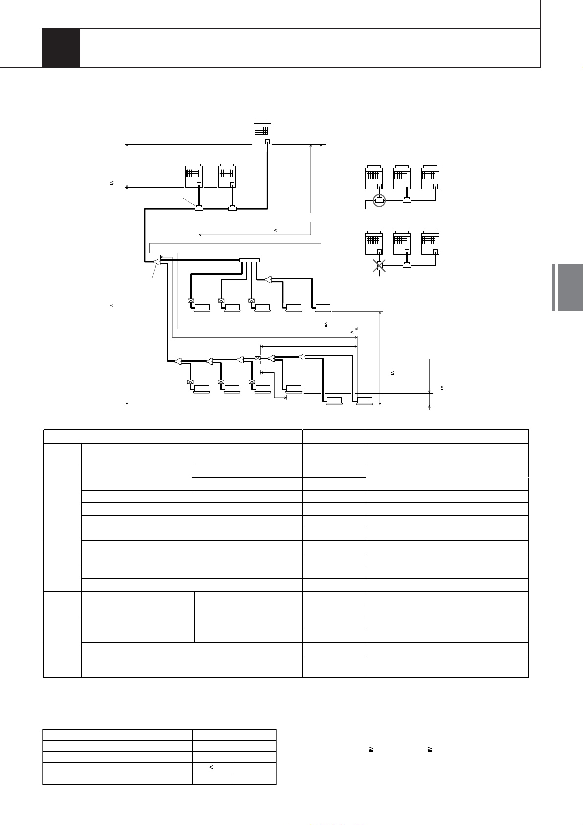
1. Allowable length/height difference of refrigerant piping
Height
difference
between
outdoor
units
H3 5m
Height
difference
between
outdoor
and indoor
units
H1 50m
Outdoor Unit
T-shape
branching
Main piping
L1
1st branching
section
Follower Unit
C
Header Unit Follower Unit
A
Branching piping
Connecting piping of
indoor unit
L3
a
ghi j
Indoor unit
Equivalent length corresponded to farthest piping
Equivalent length corresponded to farthest piping after 1st branching
L4 L5 L6 L7LhL8
def
FS unit
lmn
Indoor unit
B
La Lb Lc
LA
Main connecting piping between outdoor units
Length corresponded to farthest piping
between outdoor units
L2
bc
Branching
header
FS unit
LO 25m
L9
FS unit
< Cooling only > < Cooling only >
o
(Header)
k
Lj
Note:
In case of connecting method Ex.2, a large
amount of refrigerant and refrigerant oil may
return to the head unit. Therefore, set the T-shape
joint so that oil does not enter directly
<Ex.1> Header UnitFollower UnitFollower Unit.
<Ex.2> Header UnitFollower UnitFollower Unit
L 150m
pq
Li 50m
(q)
A B C
A B C
Height difference
between
indoor
units
H2 35m
(Upper outdoor unit)
Height difference
between indoor units
in group control by
one FS unit
H4 0.5 m
6
* Allowable length and height difference of refrigerant piping
Total extension of pipe (Liquid pipe, real length)
Farthest piping length L (*1)
Real length
Equivalent length
Max. equivalent length of main piping
Pipe
Length
Equivalent length of farthest piping from 1st branching Li (*1)
Max. real length of indoor unit connecting piping
Max. real length between FS unit and indoor unit (*2)
Max. Equivalent length of outdoor unit connecting piping LO (*1)
Max. real length of outdoor unit connecting piping
Max. equivalent length between FS unit and indoor unit Lj
Max. real length between FS unit and header indoor unit Lh (*2)
Upper outdoor unit
Lower outdoor unit
Upper outdoor unit
Lower outdoor unit
Height
Difference
Height between indoor
and outdoor units H1
Height between indoor units H2
Height between outdoor units H3
Height difference between indoor units in group control by one
FS unit H4
1 : The furthest outdoor unit from 1st branch is to be named C, and furthest indoor unit from 1st branch to be named (q).
*
2 : The supplied connection cable can be used up to 5 m in pipe length between the indoor and FS unit. When the pipe length
*
Allowable value
300 m
125 m
150 m
LA+La+Lb+Lc+L1+L2+L3+L4+L5+L6+L7+L8+9
+a+b+c+d+e+f+g+h+i+j+k+l+m+n+o+p+q
LA+Lc+L1+L3+L4+L5+L6+L7+L8+q
85 m L1
50 m L3+L4+L5+L6+L7+L8+q
30 m a+g, b+h, c+i, d+l, e+m, f+n, j, k
15 m g, h, i, l, m, n, L7+o, L7+L8+p, L7+L8+q
25 m LA+Lc (LA+Lb)
10 m La, Lb, Lc
30 m
15 m
50 m
30 m
35 m
15 m
5 m
0.5 m
L7+L8+q, L7+L8+p
L7+o
-
-
-
-
-
-
between the indoor and FS unit exceeds 5 m, you must use the connection cable kit (RBC-CBK15FE).
* System restrictions
Max. No. of combined outdoor units
Max. capacity of combined outdoor units
Max. No. of connected indoor units
Max. capacity of combined indoor units
1 : MMY-MAP1201HT8 : UP to 120 %
*
84.0 kW
48 units
H2 15m
H2
>
15m
3 units
135% (*1)
105%
Note 1) Combination of outdoor units : Header unit (1 unit) +
Follower unit (0 to 2 units). Header unit is outdoor unit
nearest to the connected indoor units
Note 2) Install the outdoor units in order of capacity.
(Header unit Follower unit 1 Follower unit 2)
Note 3) Refer to outdoor unit combination table in page.6.
Note 4) Piping to indoor units shall be perpendicular to piping to
the head outdoor unit as Ex.1.
Do not connect piping to indoor units in the same
direction of head outdoor unit as Ex.2.
Piping section
27
Page 31

Y
yp
yp
g
g
2. Selection of refrigerant piping
6
Outdoor unit
Outdoor unit
1
connecting piping
Follower UnitCFollower UnitBHeader Unit
Main connecting piping
between outdoor units
1
A
2
T-shape
9
branching joint
Balance pipe
1
Main piping3
* Selection of refrigerant piping
Discharge
No.
1
No.
2
No.
3
No.
4
5
No.
6
7
Item
Pipe size of outdoor
unit
Item
Connecting pipe size
between outdoor units
Item
Size of main pipe
Item
Pipe size between
branching sections
*1 *2 *3
Pipe size between the
end of branch and FS
unit
Item
Piping of indoor unit
Piping of cooling only
indoor unit (Between
branching and indoor
unit) *2
Suction
gas side
O
22.2
/
O
22.2
/
O
28.6
/
Suction
gas side
O
28.6
/
Suction
gas side
O
22.2
/
O
28.6
/
O
28.6
/
O
34.9
/
O
34.9
/
Suction
gas side
O
15.9
/
O
22.2
/
O
28.6
/
O
34.9
/
O
34.9
/
O
15.9
/
O
22.2
/
Suction
gas side
O
9.5
/
O
12.7
/
O
15.9
/
O
22.2
/
O
9.5
/
O
12.7
/
O
12.7
/
O
15.9
/
O
15.9
/
O
22.2
/
gas side
O
19. 1
/
O
19. 1
/
O
19. 1
/
Discharge
gas side
O
22. 2
/
Discharge
gas side
O
19. 1
/
O
19. 1
/
O
22.2
/
O
28. 6
/
O
28. 6
/
Discharge
gas side
O
12. 7
/
O
19. 1
/
O
22. 2
/
O
28. 6
/
O
28. 6
/
O
12. 7
/
O
19. 1
/
Discharge
gas side
Liquid side Outdoor unit model name
O
12.7 MMY-MAP0802FT8
/
O
12.7 MMY-MAP1002FT8
/
O
12.7
/
Liquid side
O
15.9
/
Liquid side
O
12.7 Below 33.5 Below 12
/
O
12.7 33.5
/
O
19.1 45.0 to below 61.5 16 to below 22
/
O
19.1 61.5 to below 73.0 22 to below 26
/
O
22.2
/
Liquid side
O
9.5 Below 18.0 Below 6.4
/
O
12.7 18.0 to below 34.0 6.4 to below 12.2
/
O
15.9 34.0 to below 56.5 12.2 to below 20.2
/
O
15.9 56.5 to below 70.5 20.2 to below 25.2
/
O
19.1
/
O
9.5 Below 18.0 Below 6.4
/
O
12.7
/
Liquid side
-
-
-
-
-
-
-
-
O
6.4 007 to 012 Type
/
O
6.4 015 to 018 Type
/
O
9.5 024 to 056 Type
/
O
12.7
/
O
6.4 15m or less
/
O
9.5 15m above
/
O
6.4 15m or less
/
O
9.5 15m above
/
O
9.5
/
O
12.7 072 to 096 Type
/
* Selection for branching section
No.
Y-Shape branching joint
8
Branching
Header
*4, *5, *6
9
T-Shape branching joint
(For connecting outdoor
28
*4 *5
4 Branchin
8 Branchin
unit)
For
40.0 to below 70.5 14.2 to below 25.2 RBM-HY2043FE RBM-HY2043E
For
40.0 to below 70.5 14.2 to below 25.2 RBM-HY2083FE RBM-HY2083E
1 set of 4 types of T-shape joint pipes as described below
- Balance pipe (
- Piping at liquid side (
- Piping at discharge gas side (
- Piping at suction gas side (
Total capacity code of indoor unit
Equivalent to capacity
Below 18.0 Below 6.4 RBM-BY53FE RBM-BY53E
18.0 to below 40.0 6.4 to below 14.2 RBM-BY103FE RBM-BY103E
40.0 to below 70.5 14.2 to below 25.2 RBM-BY203FE RBM-BY203E
70.5 or more 25.2 or more RBM-BY303FE RBM-BY303E
Below 40.0 Below 14.2 RBM-HY1043FE RBM-HY1043E
Below 40.0 Below 14.2 RBM-HY1083FE RBM-HY1083E
O
9.52) X 1
/
O
12.7 to
O
/
/
O
19.1 to
/
O
22.2 to
/
1st branching section
Liquid pipe
4
Discharge gas pipe
Suction gas pipe
8
4
Liquid pipe
Discharge gas pipe
Suction gas pipe
Balance
pipe
O
9.5 Below 61.5 Below 22
/
Total capacity code of all outdoor units
Total capacity code of all outdoor units
22.2) X 1
O
28.6) X 1
/
O
38.1) X 1
/
MM
Total capacity code of indoor units at
Equivalent to
capacity
Equivalent to
capacity
73.0 or more 26 or more
Equivalent to
capacity
70.5 or more 25.2 or more
18.0 or more 6.4 or more
Capacity rank of indoor unit
Equivalent to HP For 3 piping For 2 piping
10
8
10
Indoor unit
-MAP1202FT8
downstream side
Equivalent to HP
Equivalent to HP
Equivalent to HP
072 to 096 T
007 to 012 Type
015 to 018 Type
024 to 056 T
Y-Shape branching joint
8
5 5 5
FS unit
6
6 6
8
4
FS unit
6
4
5 5
5
12
e
e
4
Y-Shape branching joint
8
7 7
< Cooling only >
8
4 4
6 6 6 6 6
Selection of FS unit
10
Model Name
RBM-Y1122FE Below 11.2 Below 4.0 5
RBM-Y1802FE
RBM-Y2802FE
< Cooling only >
4
Group control
Total capacity code of
indoor unit
Equivalent to
capacity (kW)
11.2 to below
18.0
18.0 to 28.0
or less
Equivalent
4.0 to below
6.4 to 10.0
to HP
6.4
or less
* Minimum wall
thickness for R410A
application
Half
Hard
Soft
or
Hard
OK OK 1/4,, 6.35 0.80
OK OK 3/8,, 9.52 0.80
OK OK 1/2,, 12.70 0.80
OK OK 5/8,, 15.88 1.00
NG OK 3/4,, 19.05 1.00
NG OK 7/8,, 22.20 1.00
NG OK 1.1/8,, 28.58 1.00
NG OK 1.3/8,, 34.92 1.10
*1 In case the pipe exceeds the main pipe size, it
should be the same as the main pipe size.
*2 2 pipes for cooling only indoor unit shall be
used with liquid pipe and suction gas pipe.
*3 2 pipes from the FS unit to the branching section
shallbe used with liquid pipe and suction gas pipe.
*4 Branching pipe on the 1st branch should be
selected according to the capacity code of the
outdoor unit.
*5 In case total capacity code of indoor units exceeds
the capacity code of the outdoor unit,
the pipe size should be selected based on the
capacity of the outdoor unit.
*6 For 1 line after header branching, indoor units
with a total maximum capacity code of 6.0
in total can be connected.
Model Name
RBM-BT13FE
Outer
dia.
(Inch)
Outer
dia.
(mm)
Thickness
Minimum
Wall
(mm)
Max.No. of
connected
indoor
units
8
8
Page 32

3. Charging requirement with additional refrigerant
After the system has been vacuumed, replace the vacuum pump with a refrigerant cylinder and charge the
system with additional refrigerant.
Calculating the amount of additional refrigerant required
Refrigerant in the system when shipped from the factory
Refrigerant amount charged in factory Heat recovery model
8HP
11.5kg
10HP
11.5kg
R410A
12HP
11.5kg
When the system is charged with refrigerant at the factory, the amount of refrigerant needed for the pipes at the
site is not included. Therefore, calculate the additional amount needed and add the required amount to the system.
(Calculation)
Additional refrigerant charge amount is calculated based on the size of liquid pipe at site and its real length.
[Additional refrigerant charge amount at site] =
[Real length of liquid pipe] x
Additional refrigerant charge amount
per liquid pipe 1m (Table 1)
x
1.3
Example : Additional charge amount R (kg) ={(L1 x 0.025kg/m) + (L2 x 0.055kg/m) + (L3 x 0.105kg/m)
+ (L4 x 0.160kg/m) + (L5 x 0.250kg/m)} x 1.3
L1 : Real total length of liquid pipe
L2 : Real total length of liquid pipe
L3 : Real total length of liquid pipe
L4 : Real total length of liquid pipe
L5 : Real total length of liquid pipe
System : 24HP
Compensation by
+
system HP (Table 2)
6.4 (m)
9.5 (m)
12.7 (m)
15.9 (m)
19.1 (m)
6
Table 1
Pipe dia. at liquid side
Additional refrigerant amount/1m
Table 2
Combined
horse power
(HP)
8
10
12
16
18
20
24
26
28
30
Outdoor
combination (HP)
8
10
12
8
10
10
8
10
10
10
8
8
10
8
8
10
10
0.025kg
Compensation
8
8
8
10
6.4
0.055kg
by system HP
(kg)
2.0
2.5
3.0
-1.5
0.0
2.0
-4.5
-3.0
-1.5
0.0
9.5
12.7
0.105kg
15.9
0.160kg
19.1
0.250kg
22.2
0.350kg
29
Page 33

30
Page 34

7
Refrigerant cycle diagram
31
Page 35

32
Page 36

7
Refrigerant cycle diagram
Foreword
1. Inverter Unit (8,10,12HP)
Model : MMY-MAP0802FT8, MAP1002FT8, MAP1202FT8
Propeller fan
M
Fan motor
Sensor
(PMV1)
Strainer
Sensor
(TL)
Pulse motor valve
(PMV2)
Liquid
tank
Solenoid valve
(SV12)
Check valve
Strainer
(PMV3)
Solenoid
valve
Solenoid
valve
(TE1)
Str ainer
Check valve
Solenoid valve
(SV5)
Capillary
(SV6)
(SV3D)
tube
Capillary
Solenoid valve
(SV41)
(Right side)
Main heat exchanger
(Left side)
Main heat exchanger
Sub-heat exchanger
Sub-heat exchanger
Solenoid valve
(SV11)
Capillary
tube
Check valve
High pressure
sensor
Check joint
tube
Strainer
Strainer
tube
Capillary
Separator
Check
valve
Oil
Capillary
tube
Solenoid valve
(SV2)
valve
Solenoid valve
(SV42)
Check
4-way valve
Capillary
tube
Sensor
(TO)
Sensor(TS1)
Low pressure
sensor
Sensor
(TS2)
Check
joint
7
Check
joint
Strainer
Balance
pipe
service
valve
Liquid
side
service
valve
Strainer
Discharge
gas
side
service
valve
Suction
gas
side
service
valve
Strainer
Strainer
High-pressure
Switch
Sensor
(TD1)
Solenoid valve
(SV3E)
Capillary tube
Solenoid valve
Capillary
tube
Sensor
(TK3)
Check
Valve
(Inverter)
Compressor 1
Capillary tube
Sensor
(TK1)
Sensor
(TK4)
(SV3A)
Check valve
Strainer
Solenoid
(SV3C)
StrainerStrainer
Check
Valve
Capillary tube
Oil tank
valve
Sensor
(TK2)
High-pressure
Switch
Sensor
(TD2)
(Inverter)
Compressor 2
Capillary tube
Solenoid valve
(SV3B)
Check valve
Accumulator
33
Page 37

7
2. Explanation of Functional Parts
Functional part name Functional outline
Solenoid valve
4-way valve
Pulse motor valve
Oil separator
Temp. sensor
Pressure sensor
Heater
Balance pipe
34
1.SV3A
2.SV3B
3.SV3C
4.SV3D
5.SV3E
6.SV2
7.SV4(n)
8.SV5
9.SV6
10.SV11
11.SV12
PMV1,2
PMV3
1.TD1
TD2
2.TS1
3.TS2
4.TE1
5.TK1,TK2,
TK3,TK4
6.TL
7.TO
1.High pressure
sensor
2. Low pressure
sensor
Compressor case
heater
Accumulator case
heater
(Connector CN324: Red)
1) Collects oil in the oil tank during OFF time.
(Connector CN313: Blue)
1) Returns oil in the balance pipe to the compressor.
(Connector CN314: Black)
1) Pressurizes oil reserved in the oil tank during operation.
(Connector CN323: White)
1) Reserves oil in the oil separator during OFF time, and supplies oil during operation.
(Connector CN323: White)
1) Turns on during operation and balances oil between the compressors.
(Hot gas bypass) (Connector CN312: White)
1) Low pressure release function
2) High pressure release function
3) Gas balance function during off time
(Start compensation valve of compressor) (Connector CN311: Blue)
1) For gas balance start
2) High pressure release function
3) Low pressure release function
(Connector CN310: White)
1) For gas balance during operation mode change
2) For low pressure balance in all cooling operation
(Connector CN309 : White)
1) Liquid bypass function for releasing discharge temperature
(Connector CN322 : White)
1) Discharge gas line shut-down function in all cooling and defrosting operation
(Connector CN319 : White)
1) Controls flow rate for sub-heat exchanger in simultaneous operation
2) Controls flow rate for sub-heat exchanger when defrosting
(Connector CN317: Blue)
1) Cooling/heating exchange 2)Reverse defrost
3) Main/sub heat exchager exchange
(Connector CN300, 301: White)
1) Super heat control function in all heating and majority heating operation
2) Sub-cool adjustment function in cooling operation
3) Distribution control in simultaneous operation
(Connector CN302 : Red)
1) Controls flow rate for sub-heat exchanger in simultaneous operation
2) Preventive function for high-pressure rising in all cooling and all heating operation
1) Prevention for rapid decreasing of oil (Decreases oil flowing into the refrigeration cycle)
2) Reserve function of surplus oil
(TD1: Connector, CN502: White, TD2: Connector, CN503: Pink)
1) Protection of compressor discharge temp. Used for release
(Connector CN504: White)
1) Controls super heat in heating operation
(Connector CN522 : Black)
1) For refrigerant recovery control in all cooling and majority cooling operation
2) Detects overheating on refigeration cycle.
(Connector CN505: Green)
1) Controls defrost in all heating and majority heating operation
2) Controls outdoor fan in all heating and simultaneous operation
TK1 Connector CN514: Black, TK2 Connector CN515: Green,
()
TK3 Connector CN516: Red, TK4 Connector CN523: Yellow
1) Determines oil level of the compressor
(Connector CN521: White)
1) Detects sub-cool in all cooling and simultaneous operation
(Connector CN507: Yellow)
1) Detects outside temperature
(Connector CN501: Red)
1) Detects high pressure and controls compressor capacity
2) Detects high pressure in all cooling operation, and controls the fan in low ambient
cooling operation
3) Controls sub-cool of heating indoor unit.
4) Controls outdoor fan speed in majority cooling operation.
(Connector CN500: White)
1) Detects low pressure in all cooling and simultaneous operation and controls compressor capacity
2) Detects low pressure in all heating and simultaneous operation, and controls the super heat
(Compressor 1 Connector CN316: White, Compressor 2 Connector CN315: Blue)
1) Prevents liquid accumulation to the compressor
(Connector CN321: Red)
1) Prevents liquid accumulation to the accumulator
1) Oil balancing in each outdoor unit (This model doesn't use balance pipe)
Page 38

3. Heat Exchanger of Outdoor Unit
Propeller Fan
Fan motor
Main Heat Exchanger
Air
Direction
Air
Direction
Sub
Heat Exchanger
Sub
Heat Exchanger
Front side
(Left)
Rear side
(Right)
4. FS Unit (Flow Selector Unit)
Model RBM-Y1122FE Model RBM-Y1802FE Model RBM-Y2802FE
Strainer
Capillary
tube
SVSS
Suction gasDischarge gasLiquid
PipePipePipe
SVS
Check valve
Capillary
tube
Check
valve
Strainer
SVD
Capillary
SVDD
tube
Strainer
Capillary
tube
SVSS
Pipe
Capillary
Check valve
Strainer
tube
Check
valve
SVD
Capillary
tube
SVDD
Capillary
SVSS
Suction gasDischarge gasLiquid
Strainer
tube
PipePipe
SVS
Check valve
Capillary
tube
Check
valve
Strainer
SVD
Capillary
tube
SVDD
7
Suction gasDischarge gasLiquid
PipePipePipe
SVS
To liquid side
of indoor unit
Functional part name
Solenoid
SVD
Valve
SVS
SVDD
SVSS
Strainer
To gas side
of indoor unit
To liquid side
of indoor unit
Strainer
of indoor unit
To gas side
To liquid side
of indoor unit
Functional outline
(Discharge gas pipe shut-down valve)
1) High pressure line in heating
(Suction gas pipe shut-down valve)
1) Low pressure line in cooling
(Pressurization valve)
Pressurizes indoor unit during the ON operation when indoor unit starts heating.
1)
(Depressurization valve)
1)
Returns refrigerant in indoor unit when stopped or in thermo-OFF status.
2)
Depressurizes indoor unit during the ON operation when the indoor unit stops heating.
Strainer
To gas side
of indoor unit
35
Page 39

7
5. Indoor Unit
Liquid side Gas side
7
Strainer
Pulse Motor
Valve (PMV)
Sensor
(TC2)
(NOTE) MMU-AP0071YH to AP0121YH type air conditioners do not have a TC2 sensor.
Capillary tube
Strainer
Sensor
(TCJ)
Air heat exchanger
at indoor side
Fan
Sensor
(TA)
M
Fan motor
Sensor
(TC1)
Pulse Motor Valve
Temp. sensor
36
Functional part name Functional outline
PMV
1. TA
2. TC1
3. TC2
4. TCJ
(Connector CN082 (6P): Blue)
1)Controls super heat in cooling operation
2)Controls sub-cooling in heating operation
3)Recovers refrigerant oil in cooling operation
4)Recovers refrigerant oil in heating operation
(Connector CN104 (2P): Yellow)
1)Detects indoor suction temperature
(Connector CN100 (3P): Brown)
1)Controls PMV super heat in cooling operation
(Connector CN101 (2P): Black)
1)Controls PMV sub-cool in heating operation
(Connector CN102 (2P): Red)
1)Controls PMV super heat in cooling operation
2)[MMU-AP0071 to AP0121YH only]
Controls PMV sub-cool in heating operation
Page 40

6. SYSTEMATIC DRAWING
1. All Cooling Operation (Outdoor temperature : 10 or more)
PMV1
TL
Li quid
Tank
PMV2
V
S
PMV3
Header Unit
TE1
1
2
SV11
SV5
6
V
S
Co n d e n s er
Co n d e n s er
Pd Sen s or
SV3D
SV4 1
TD1
SV3E
FM
OS
T
1
Compressor
TK1
TK4
Follower Unit
Condenser
Condenser
Pd Sen s or
SV3D
SV4 1
TD1
SV3E
FM
OS
T
1
Compressor
TK1
TK4
TO
4- way
OF F
val ve
TS1
Ps sensor
S
T
2
SV2
SV42
HPHP
SV3C
TD2
3
K
Compressor
TK2
Oil tank
Ac cumul a t or
7
2
S
PMV3
V
1
SV5
V
S
TE1
2
SV11
6
TO
PMV1
PMV2
4- way
OF F
val ve
TS1
Ps s ens or
S
T
2
SV2
SV42
HPHP
SV3C
TD2
3
K
Compressor
TK2
Oil tank
Ac cumul a t or
2
TL
Li quid
Tank
Flow
Selector
Unit
Indoor
Unit
PMV
TC2
SVD
SVDD
SVSS
T
C
J
Outdoor unit
4WV
SV4(n)
SV5
SV6
SV11
SV12
Fan
(*1) Turns on during compressor off status.
OFF
(*1)
ON
Control
OFF
OFF
Control
SV3A
SV3B
SV3C
SV3D
SV3E
PMV1,2
PMV3
Control
Control
Control
Control
ON
Control
Close
SV3A
SV3B
Suction gas pipe
Discharge gas pipe
Liquid pipe
SVS
STST
TC1
PMV
TC2
SVD
SVDD
T
C
J
SVSS
SVS
STST
TC1
PMV
TC2
SVD
SVDD
T
C
J
SV3A
SVS
SVSS
STST
TC1
Cooling Cooling Cooling
FS unit and Indoor unit
Cooling thermo-ON
SVD
SVS
SVDD
SVSS
PMV
OFF
ON
OFF
ON
Control
SVD
SVS
SVDD
SVSS
PMV
Stop
OFF
OFF
OFF
ON
Close
SV3B
SVS
SVSS
STST
TC1
PMV
TC2
SVD
SVDD
T
C
J
Stop
High-pressure gas or condensate
liquid refrigerant
Low-pressure gas
Low-pressure gas
(refrigerant recovery line)
High-pressure refrigerant
(plunging circuit)
37
Page 41

2. All Cooling Operation (Outdoor temperature : 10 or more)
7
PMV1
TL
Li quid
Tank
PMV2
S
PMV3
V
1
2
SV5
V
S
TE1
SV11
6
Header Unit
FM
Condenser
Condenser
Pd Sen s or
OS
SV3D
SV4 1
TD1
3
K
T
1
Compressor
TK1
SV3E
TK4
SV3C
TK2
Oil tank
4- way
val ve
SV2
TD2
2
Compressor
SV42
HPHP
TO
ON
TS1
S
T
Ps s ens or
2
Ac cumul a t or
PMV1
TL
Li quid
Follower Unit
Pd Sen s or
SV3D
SV4 1
Condenser
Condenser
TD1
SV3E
FM
OS
T
1
Compressor
TK1
TK4
TO
4- way
ON
val ve
TS1
Ps s ens or
S
T
2
SV2
SV42
HPHP
SV3C
3
K
Compressor
TK2
Oil tank
Ac cumul a t or
TD2
2
TE1
1
2
V
S
PMV2
PMV3
SV11
SV5
6
V
S
Tank
Flow
Selector
Unit
Indoor
Unit
PMV
TC2
SVD
SVDD
SVSS
T
C
J
Cooling Cooling Cooling Stop
Outdoor unit
4WV
SV4(n)
SV5
SV6
SV11
SV12
Fan
(*1) Turns on during compressor off status.
(*2) Control depends on the operation status.
ON
(*1)
OFF
Control
ON
Control
Control
SV3A
SV3B
SV3C
SV3D
SV3E
PMV1,2
PMV3
Control
Control
Control
Control
ON
Control
Close
(*2)
SV3A
SVS
STST
PMV
TC1
Cooling thermo-ON
SVD
SVS
SVDD
SVSS
PMV
SV3B
Suction gas pipe
Discharge gas pipe
Liquid pipe
SVD
SVDD
SVSS
TC2
T
C
J
FS unit and Indoor unit
OFF
ON
OFF
ON
Control
SVS
STST
TC1
SVD
SVS
SVDD
SVSS
PMV
Stop
PMV
TC2
OFF
OFF
OFF
Close
ON
SV3A
SV3B
SVSS
SVS
STST
TC1
SVD
SVDD
PMV
TC2
T
C
J
High-pressure gas or condensate
liquid refrigerant
SVD
SVDD
T
C
J
SVS
SVSS
STST
TC1
Low-pressure gas
Low-pressure gas
(refrigerant recovery line)
High-pressure refrigerant
(plunging circuit)
38
Page 42

3. All Heating Operation
High-pressure gas or condensate liquid refrigerant
Low-pressure gas (refrigerant recovery line)
Low-pressure gas
High-pressure refrigerant (plunging circuit)
PMV1
TL
Li quid
Tank
PMV2
V
S
PMV3
Header Unit
TE1
1
2
SV11
SV5
6
V
S
Evaporator
Evaporator
Pd Sen s or
SV3D
SV4 1
TD1
Compressor
SV3E
FM
Follower Unit
SV11
Pd Sen s or
SV3D
SV4 1
FM
Evaporator
Evaporator
OS
TD1
3
K
T
1
Compressor
TK1
SV3E
TK4
SV3C
TK2
Oil tank
4- way
val ve
SV2
TD2
2
Compressor
SV42
HPHP
TO
ON
TS1
S
T
2
Ac cumul a t or
Ps s ens or
7
S
PMV3
TE1
1
2
V
SV5
6
V
S
TO
PMV1
PMV2
4- way
ON
val ve
TS1
Ps s ens or
S
T
2
SV2
OS
SV42
HPHP
SV3C
TD2
3
K
T
1
TK1
TK4
TK2
Oil tank
Compressor
Ac cumul a t or
2
TL
Li quid
Tank
Flow
Selector
Unit
Indoor
Unit
PMV
TC2
SVD
SVDD
SVSS
T
C
J
Heating Heating Heating Stop
Outdoor unit
4WV
SV4(n)
SV5
SV6
SV11
SV12
Fan
(*1) Turn on during compressor stop status.
(*2) Control based on operation status.
ON
(*1)
OFF
Control
ON
OFF
Control
SV3A
SV3B
SV3C
SV3D
SV3E
PMV1,2
PMV3
SV3A
STST
SVS
TC1
PMV
TC2
Control
ON
Control
Control
ON
Control
Close
SV3B
Discharge gas pipe
SVD
T
C
J
(*2)
Suction gas pipe
Liquid pipe
SVDD
SVSS
Heating thermo-ON
SVD
SVS
SVDD
SVSS
PMV
STST
SVS
TC1
PMV
TC2
SVD
T
C
J
FS unit and Indoor unit
Heating thermo-OFF
ON
OFF
OFF
OFF
Control
SVD
SVS
SVDD
SVSS
PMV
SVDD
SVSS
OFF
OFF
OFF
OFF
Close
SV3A
STST
SVS
TC1
PMV
TC2
SVD
SVS
SVDD
SVSS
PMV
T
C
J
Stop
SV3B
SVD
OFF
OFF
OFF
ON
Close
SVDD
SVS
SVSS
STST
TC1
39
Page 43

4. Mainly Cooling, Partly Heating Operation
High-pressure gas or condensate liquid refrigerant
Low-pressure gas (refrigerant recovery line)
Header Unit
Low-pressure gas
High-pressure refrigerant (plunging circuit)
Follower Unit
7
PMV1
TL
Li quid
Tank
PMV2
S
PMV3
V
1
SV5
S
Pd Sen s or
SV3D
SV4 1
Condenser
Condenser
TD1
Compressor
SV3E
FM
1
SV3A
V
S
PMV3
1
SV5
S
TE1
2
SV11
6
V
TO
PMV1
PMV2
4- way
ON
val ve
TS1
Ps s ens or
S
T
2
SV2
OS
SV42
HPHP
SV3C
3
K
T
Compressor
TK1
TK2
Oil tank
TK4
Ac cumul a t or
TD2
2
SV3B
TL
Li quid
Tank
TE1
2
SV11
6
V
Pd Sen s or
SV3D
SV4 1
Condenser
Condenser
TD1
Compressor
SV3E
FM
1
SV3A
TO
4- way
ON
val ve
TS1
Ps sensor
S
T
2
SV2
OS
SV42
HPHP
SV3C
3
K
T
Compressor
TK1
TK2
Oil tank
TK4
Ac cumul a t or
TD2
2
SV3B
Flow
Selector
Unit
Indoor
Unit
PMV
TC2
SVD
SVDD
SVSS
T
C
J
Cooling Cooling HeatingStop
Outdoor unit
4WV
SV4(n)
SV5
SV6
SV11
SV12
Fan
(*1) Turns on during compressor off status.
(*2) Control based on operation status.
ON
(*1)
OFF
Control
ON
Control
Control
SV3A
SV3B
SV3C
SV3D
SV3E
PMV1,2
PMV3
STST
SVS
TC1
Control
Control
Control
Control
Close
PMV
ON
Close
TC2
T
C
J
(*2)
Suction gas pipe
Discharge gas pipe
Liquid pipe
SVD
SVDD
SVSS
Cooling, thermo-ON
SVD
SVS
SVDD
SVSS
PMV
SVS
STST
TC1
Control
SVD
SVDD
PMV
TC2
T
C
J
FS unit and Indoor unit
Heating thermo-ON
OFF
ON
OFF
ON
SVD
SVS
SVDD
SVSS
PMV
SVSS
ON
OFF
OFF
OFF
Control
SVS
STST
TC1
PMV
TC2
SVD
SVDD
T
C
J
SVS
SVSS
STST
TC1
Stop
SVD
SVS
SVDD
SVSS
PMV
OFF
OFF
OFF
ON
Close
40
Page 44

5. Mainly Heating, Partly Cooling Operation
High-pressure gas or condensate liquid refrigerant
Low-pressure gas (refrigerant recovery line)
Low-pressure gas
High-pressure refrigerant (plunging circuit)
PMV1
TL
Li quid
Tank
PMV2
V
S
PMV3
1
SV5
V
S
TE1
2
SV11
6
Header Unit
FM
Evaporator
Evaporator
Pd Sen s or
OS
SV3D
SV4 1
TD1
3
K
T
1
Compressor
TK1
SV3E
Oil tank
TK4
SV3C
TK2
4- way
val ve
SV2
TD2
Compressor
Follower Unit
Evaporator
Evaporator
Pd Sen s or
SV3D
SV4 1
TD1
Compressor
SV3E
FM
TO
4- way
ON
val ve
TS1
Ps s ens or
S
T
2
SV2
OS
SV42
HPHP
SV3C
TD2
3
K
T
1
TK1
TK4
TK2
Oil tank
Compressor
Ac cumul a t or
2
7
S
V
PMV3
SV5
S
TE1
1
2
SV11
6
V
TO
PMV1
PMV2
ON
TS1
Ps s ens or
S
T
2
TL
SV42
HPHP
Ac cumul a t or
2
Li quid
Tank
Flow
Selector
Unit
Indoor
Unit
PMV
TC2
SVD
SVDD
SVSS
T
C
J
Outdoor unit
4WV
SV4(n)
SV5
SV6
SV11
SV12
Fan
(*1) Turns on during compressor off status.
(*2) Control based on operation status.
ON
(*1)
OFF
Control
ON
Close
Control
(*2)
SV3A
SV3B
Suction gas pipe
Discharge gas pipe
Liquid pipe
SVS
STST
TC1
PMV
TC2
SVD
SVDD
T
C
J
SVSS
SVS
STST
TC1
PMV
TC2
SVD
SVDD
T
C
J
SVSS
SV3A
STST
SVS
TC1
PMV
TC2
SV3B
SVD
SVDD
T
C
J
SVS
SVSS
STST
TC1
Heating Heating Stop Cooling
FS unit and Indoor unit
SV3A
SV3B
SV3C
SV3D
SV3E
PMV1,2
PMV3
Control
Control
Control
Control
ON
Control
Close
(*2)
Heating thermo-ON
SVD
SVS
SVDD
SVSS
PMV
OFF
ON
OFF
ON
Control
Heating thermo-OFF
SVD
SVS
SVDD
SVSS
PMV
ON
OFF
OFF
OFF
Control
SVD
SVS
SVDD
SVSS
PMV
Stop
OFF
OFF
OFF
ON
Close
41
Page 45

6. Defrosting
High-pressure gas or condensate liquid refrigerant
Low-pressure gas
Low-pressure gas (refrigerant recovery line)
7
PMV1
TL
Liquid
Tank
PMV2
V
S
PMV3
SV5
S
Header Unit
TE1
1
2
SV11
V
6
SV3D
Pd S ensor
SV41
TD1
SV3E
FM
OS
T
1
Compressor
TK1
TK 4
SV3A
Follower Unit
Pd S ensor
SV3D
SV41
SV3E
TD1
Compressor
FM
1
SV3A
TK1
TO
4-way
OFF
valve
TS1
Ps sensor
T
S
2
SV2
OS
SV42
HPHP
SV3C
TD2
K
3
T
Compressor
TK2
Oil tank
TK 4
Accumulator
2
SV3B
V
S
PMV3
1
SV5
S
TE1
2
SV11
V
6
TO
PMV1
PMV2
4-way
OFF
valve
TS1
Ps sensor
T
S
2
SV2
SV42
HPHP
SV3C
TD2
K
3
Compressor
TK2
Oil tank
Accumulator
2
SV3B
TL
Liquid
Tank
Flow
Selector
Unit
Indoor
Unit
Suction gas pipe
Discharge gas pipe
Liquid pipe
PMV
TC2
SVD
SVDD
T
C
J
SVS
SVSS
STST
TC1
Cooling
indoor unit
PMV
TC2
T
SVD
SVDD
C
J
Heating
indoor unit
SVSS
SVS
STST
TC1
PMV
TC2
SVD
SVDD
T
C
J
Heating
indoor unit
SVSS
SVS
STST
TC1
PMV
TC2
SVD
T
C
J
Stop
indoor unit
Defrosting is performed during "All heating" or "Mainly heating, partly cooling" operation.
Outdoor unit
4WV
SV4(n)
SV5
SV6
SV11
SV12
Fan
OFF
(*1)
ON
Control
OFF
Close
Stop
(*1) Turns on during compressor off status.
(*2) Control based on operation status.
(*2)
SV3A
SV3B
SV3C
SV3D
SV3E
PMV1,2
PMV3
OFF
OFF
OFF
Control
ON
Control
Control
FS unit and Indoor unit
Cooling thermo-ON
SVD
SVS
SVDD
SVSS
PMV
Fan
OFF
ON
OFF
ON
Control
Control
SVD
SVS
SVDD
SVSS
PMV
Fan
Others
OFF
ON
OFF
ON
Control
Stop
SVDD
SVS
SVSS
STST
TC1
42
Page 46

8
Sensible capacity table
43
Page 47

44
Page 48

8
Sensible capacity table
4-way Discharge Cassette Type ( MMU-AP****H )
unit
outdoor
size
air temp.
DB TC SHC TC SHC TC SHC TC SHC TC SHC TC SHC TC SHC
10.0 2.3 1.9 2.5 2.0 2.7 2.1 2.8 2.1 2.9 2.1 3.1 2.1 3.2 2.0
12.0 2.3 1.9 2.5 2.0 2.7 2.1 2.8 2.1 2.9 2.1 3.1 2.1 3.2 2.0
14.0 2.3 1.9 2.5 2.0 2.7 2.1 2.8 2.1 2.9 2.1 3.1 2.1 3.2 2.0
16.0 2.3 1.9 2.5 2.0 2.7 2.1 2.8 2.1 2.9 2.1 3.1 2.1 3.2 2.0
18.0 2.3 1.9 2.5 2.0 2.7 2.1 2.8 2.1 2.9 2.1 3.1 2.1 3.2 2.0
20.0 2.3 1.9 2.5 2.0 2.7 2.1 2.8 2.1 2.9 2.1 3.1 2.1 3.2 2.0
21.0 2.3 1.9 2.5 2.0 2.7 2.1 2.8 2.1 2.9 2.1 3.1 2.1 3.2 2.0
009 23.0 2.3 1.9 2.5 2.0 2.7 2.1 2.8 2.1 2.9 2.1 3.1 2.1 3.2 2.0
25.0 2.3 1.9 2.5 2.0 2.7 2.1 2.8 2.1 2.9 2.1 3.1 2.1 3.2 2.0
27.0 2.3 1.9 2.5 2.0 2.7 2.1 2.8 2.1 2.9 2.1 3.1 2.1 3.2 2.0
29.0 2.3 1.9 2.5 2.0 2.7 2.1 2.8 2.1 2.9 2.1 3.1 2.1 3.2 2.0
31.0 2.3 1.9 2.5 2.0 2.7 2.1 2.8 2.1 2.9 2.1 3.1 2.1 3.2 2.0
33.0 2.3 1.9 2.5 2.0 2.7 2.1 2.8 2.1 2.9 2.1 3.1 2.1 3.2 2.0
35.0 2.3 1.9 2.5 2.0 2.7 2.1 2.8 2.1 2.9 2.1 3.1 2.1 3.2 2.0
37.0 2.2 1.8 2.5 1.9 2.6 2.0 2.7 2.0 2.8 2.0 3.0 2.0 3.1 2.0
39.0 2.2 1.8 2.4 1.9 2.6 2.0 2.6 2.0 2.7 2.0 2.9 2.0 3.0 1.9
10.0 3.0 2.3 3.3 2.5 3.5 2.6 3.6 2.6 3.7 2.6 3.9 2.6 4.1 2.5
12.0 3.0 2.3 3.3 2.5 3.5 2.6 3.6 2.6 3.7 2.6 3.9 2.6 4.1 2.5
14.0 3.0 2.3 3.3 2.5 3.5 2.6 3.6 2.6 3.7 2.6 3.9 2.6 4.1 2.5
16.0 3.0 2.3 3.3 2.5 3.5 2.6 3.6 2.6 3.7 2.6 3.9 2.6 4.1 2.5
18.0 3.0 2.3 3.3 2.5 3.5 2.6 3.6 2.6 3.7 2.6 3.9 2.6 4.1 2.5
20.0 3.0 2.3 3.3 2.5 3.5 2.6 3.6 2.6 3.7 2.6 3.9 2.6 4.1 2.5
21.0 3.0 2.3 3.3 2.5 3.5 2.6 3.6 2.6 3.7 2.6 3.9 2.6 4.1 2.5
012 23.0 3.0
25.0 3.0 2.3 3.3 2.5 3.5 2.6 3.6 2.6 3.7 2.6 3.9 2.6 4.1 2.5
27.0 3.0 2.3 3.3 2.5 3.5 2.6 3.6 2.6 3.7 2.6 3.9 2.6 4.1 2.5
29.0 3.0 2.3 3.3 2.5 3.5 2.6 3.6 2.6 3.7 2.6 3.9 2.6 4.1 2.5
31.0 3.0 2.3 3.3 2.5 3.5 2.6 3.6 2.6 3.7 2.6 3.9 2.6 4.1 2.5
33.0 3.0 2.3 3.3 2.5 3.5 2.6 3.6 2.6 3.7 2.6 3.9 2.6 4.1 2.5
35.0 3.0 2.3 3.3 2.5 3.5 2.6 3.6 2.6 3.7 2.6 3.9 2.6 4.1 2.5
37.0 2.9 2.2 3.2 2.4 3.4 2.5 3.5 2.5 3.6 2.5 3.8 2.5 4.0 2.4
39.0 2.8 2.2 3.1 2.3 3.3 2.5 3.4 2.4 3.5 2.4 3.7 2.4 3.9 2.4
10.0 3.7 2.8 4.1 3.0 4.4 3.2 4.5 3.2 4.6 3.2 4.9 3.2 5.1 3.1
12.0 3.7 2.8 4.1 3.0 4.4 3.2 4.5 3.2 4.6 3.2 4.9 3.2 5.1 3.1
14.0 3.7 2.8 4.1 3.0 4.4 3.2 4.5 3.2 4.6 3.2 4.9 3.2 5.1 3.1
16.0 3.7 2.8 4.1 3.0 4.4 3.2 4.5 3.2 4.6 3.2 4.9 3.2 5.1 3.1
18.0 3.7 2.8 4.1 3.0 4.4 3.2 4.5 3.2 4.6 3.2 4.9 3.2 5.1 3.1
20.0 3.7 2.8 4.1 3.0 4.4 3.2 4.5 3.2 4.6 3.2 4.9 3.2 5.1 3.1
21.0 3.7 2.8 4.1 3.0 4.4 3.2 4.5 3.2 4.6 3.2 4.9 3.2 5.1 3.1
015 23.0 3.7 2.8 4.1 3.0 4.4 3.2 4.5 3.2 4.6 3.2 4.9 3.2 5.1 3.1
25.0 3.7 2.8 4.1 3.0 4.4 3.2 4.5 3.2 4.6 3.2 4.9 3.2 5.1 3.1
27.0 3.7 2.8 4.1 3.0 4.4 3.2 4.5 3.2 4.6 3.2 4.9 3.2 5.1 3.1
29.0 3.7 2.8 4.1 3.0 4.4 3.2 4.5 3.2 4.6 3.2 4.9 3.2 5.1 3.1
31.0 3.7 2.8 4.1 3.0 4.4 3.2 4.5 3.2 4.6 3.2 4.9 3.2 5.1 3.1
33.0 3.7 2.8 4.1 3.0 4.4 3.2 4.5 3.2 4.6 3.2 4.9 3.2 5.1 3.1
35.0 3.7 2.8 4.1 3.0 4.4 3.2 4.5 3.2 4.6 3.2 4.9 3.2 5.1 3.1
37.0 3.6 2.7 4.0 2.9 4.2 3.1 4.4 3.1 4.5 3.1 4.7 3.1 5.0 3.0
39.0 3.5 2.7 3.8 2.8 4.1 3.0 4.2 3.0 4.4 3.0 4.6 3.0 4.8 2.9
10.0 4.6 3.5 5.1 3.8 5.4 4.0 5.6 4.0 5.8 4.0 6.1 4.0 6.4 3.9
12.0 4.6 3.5 5.1 3.8 5.4 4.0 5.6 4.0 5.8 4.0 6.1 4.0 6.4 3.9
14.0 4.6 3.5 5.1 3.8 5.4 4.0 5.6 4.0 5.8 4.0 6.1 4.0 6.4 3.9
16.0 4.6 3.5 5.1 3.8 5.4 4.0 5.6 4.0 5.8 4.0 6.1 4.0 6.4 3.9
18.0 4.6 3.5 5.1 3.8 5.4 4.0 5.6 4.0 5.8 4.0 6.1 4.0 6.4 3.9
20.0 4.6 3.5 5.1 3.8 5.4 4.0 5.6 4.0 5.8 4.0 6.1 4.0 6.4 3.9
21.0 4.6 3.5 5.1 3.8 5.4 4.0 5.6 4.0 5.8 4.0 6.1 4.0 6.4 3.9
018 23.0 4.6 3.5 5.1 3.8 5.4 4.0 5.6 4.0 5.8 4.0 6.1 4.0 6.4 3.9
25.0 4.6 3.5 5.1 3.8 5.4 4.0 5.6 4.0 5.8 4.0 6.1 4.0 6.4 3.9
27.0 4.6 3.5 5.1 3.8 5.4 4.0 5.6 4.0 5.8 4.0 6.1 4.0 6.4 3.9
29.0 4.6 3.5 5.1 3.8 5.4 4.0 5.6 4.0 5.8 4.0 6.1 4.0 6.4 3.9
31.0 4.6 3.5 5.1 3.8 5.4 4.0 5.6 4.0 5.8 4.0 6.1 4.0 6.4 3.9
33.0 4.6 3.5 5.1 3.8 5.4 4.0 5.6 4.0 5.8 4.0 6.1 4.0 6.4 3.9
35.0 4.6 3.5 5.1 3.8 5.4 4.0 5.6 4.0 5.8 4.0 6.1 4.0 6.4 3.9
37.0 4.5 3.4 4.9 3.7 5.3 3.9 5.4 3.9 5.6 3.9 5.9 3.8 6.2 3.7
39.0 4.3 3.3 4.8 3.6 5.1 3.8 5.3 3.8 5.4 3.8 5.7 3.7 6.0 3.6
14.0 WB 16.0 WB 18.0 WB 19.0 WB 20.0 WB 22.0 WB 24.0 WB
DB 23 DB 26 DB 27 DB 28 DB 30 DB 32 DB
20
2.3
3.3 2.5 3.5 2.6 3.6 2.6 3.7 2.6 3.9 2.6 4.1 2.5
indoor air temp.
TC : Total capacity [kW] SHC : Sensible capacity [kW]
8
45
Page 49

8
4-way Discharge Cassette Type ( MMU-AP****H )
indoor air temp.
unit
outdoor
size
air temp.
DB TC SHC TC SHC TC SHC TC SHC TC SHC TC SHC TC SHC
10.0 5.8 4.3 6.4 4.6 6.9 4.9 7.1 4.9 7.3 4.9 7.7 4.9 8.1 4.7
12.0 5.8 4.3 6.4 4.6 6.9 4.9 7.1 4.9 7.3 4.9 7.7 4.9 8.1 4.7
14.0 5.8 4.3 6.4 4.6 6.9 4.9 7.1 4.9 7.3 4.9 7.7 4.9 8.1 4.7
16.0 5.8 4.3 6.4 4.6 6.9 4.9 7.1 4.9 7.3 4.9 7.7 4.9 8.1 4.7
18.0 5.8 4.3 6.4 4.6 6.9 4.9 7.1 4.9 7.3 4.9 7.7 4.9 8.1 4.7
20.0 5.8 4.3 6.4 4.6 6.9 4.9 7.1 4.9 7.3 4.9 7.7 4.9 8.1 4.7
21.0 5.8 4.3 6.4 4.6 6.9 4.9 7.1 4.9 7.3 4.9 7.7 4.9 8.1 4.7
024 23.0 5.8 4.3 6.4 4.6 6.9 4.9 7.1 4.9 7.3 4.9 7.7 4.9 8.1 4.7
25.0 5.8 4.3 6.4 4.6 6.9 4.9 7.1 4.9 7.3 4.9 7.7 4.9 8.1 4.7
27.0 5.8 4.3 6.4 4.6 6.9 4.9 7.1 4.9 7.3 4.9 7.7 4.9 8.1 4.7
29.0 5.8 4.3 6.4 4.6 6.9 4.9 7.1 4.9 7.3 4.9 7.7 4.9 8.1 4.7
31.0 5.8 4.3 6.4 4.6 6.9 4.9 7.1 4.9 7.3 4.9 7.7 4.9 8.1 4.7
33.0 5.8 4.3 6.4 4.6 6.9 4.9 7.1 4.9 7.3 4.9 7.7 4.9 8.1 4.7
35.0 5.8 4.3 6.4 4.6 6.9 4.9 7.1 4.9 7.3 4.9 7.7 4.9 8.1 4.7
37.0 5.6 4.2 6.2 4.5 6.7 4.8 6.9 4.7 7.1 4.7 7.5 4.7 7.8 4.6
39.0 5.5 4.1 6.1 4.4 6.5 4.6 6.7 4.6 6.9 4.6 7.3 4.6 7.6 4.5
10.0 6.6 4.9 7.3 5.2 7.8 5.5 8.0 5.5 8.2 5.5 8.7 5.4 9.1 5.3
12.0 6.6 4.9 7.3 5.2 7.8 5.5 8.0 5.5 8.2 5.5 8.7 5.4 9.1 5.3
14.0 6.6 4.9 7.3 5.2 7.8 5.5 8.0 5.5 8.2 5.5 8.7 5.4 9.1 5.3
16.0 6.6 4.9 7.3 5.2 7.8 5.5 8.0 5.5 8.2 5.5 8.7 5.4 9.1 5.3
18.0 6.6 4.9 7.3 5.2 7.8 5.5 8.0 5.5 8.2 5.5 8.7 5.4 9.1 5.3
20.0 6.6 4.9 7.3 5.2 7.8 5.5 8.0 5.5 8.2 5.5 8.7 5.4 9.1 5.3
21.0 6.6 4.9 7.3 5.2 7.8 5.5 8.0 5.5 8.2 5.5 8.7 5.4 9.1 5.3
027 23.0 6.6 4.9 7.3 5.2 7.8 5.5 8.0 5.5 8.2 5.5 8.7 5.4 9.1 5.3
25.0 6.6 4.9 7.3 5.2 7.8 5.5 8.0 5.5 8.2 5.5 8.7 5.4 9.1 5.3
27.0 6.6 4.9 7.3 5.2 7.8 5.5 8.0 5.5 8.2 5.5 8.7 5.4 9.1 5.3
29.0 6.6 4.9 7.3 5.2 7.8 5.5 8.0 5.5 8.2 5.5 8.7 5.4 9.1 5.3
31.0 6.6 4.9 7.3 5.2 7.8 5.5 8.0 5.5 8.2 5.5 8.7 5.4 9.1 5.3
33.0 6.6 4.9 7.3 5.2 7.8 5.5 8.0 5.5 8.2 5.5 8.7 5.4 9.1 5.3
35.0 6.6 4.9 7.3 5.2 7.8 5.5 8.0 5.5 8.2 5.5 8.7 5.4 9.1 5.3
37.0 6.4 4.7 7.0 5.0 7.5 5.3 7.7 5.3 8.0 5.3 8.4 5.3 8.8 5.2
39.0 6.2 4.6 6.8 4.9 7.3 5.2 7.5 5.2 7.8 5.2 8.2 5.1 8.6 5.0
10.0 7.4 5.5 8.2 5.9 8.7 6.2 9.0 6.2 9.3 6.2 9.8 6.1 10.3 6.0
12.0 7.4 5.5 8.2 5.9 8.7 6.2 9.0 6.2 9.3 6.2 9.8 6.1 10.3 6.0
14.0 7.4 5.5 8.2 5.9 8.7 6.2 9.0 6.2 9.3 6.2 9.8 6.1 10.3 6.0
16.0 7.4 5.5 8.2 5.9 8.7 6.2 9.0 6.2 9.3 6.2 9.8 6.1 10.3 6.0
18.0 7.4 5.5 8.2 5.9 8.7 6.2 9.0 6.2 9.3 6.2 9.8 6.1 10.3 6.0
20.0 7.4 5.5 8.2 5.9 8.7 6.2 9.0 6.2 9.3 6.2 9.8 6.1 10.3 6.0
21.0 7.4 5.5 8.2 5.9 8.7 6.2 9.0 6.2 9.3 6.2 9.8 6.1 10.3 6.0
030 23.0 7.4 5.5 8.2 5.9 8.7 6.2 9.0 6.2 9.3 6.2 9.8 6.1 10.3 6.0
25.0 7.4 5.5 8.2 5.9 8.7 6.2 9.0 6.2 9.3 6.2 9.8 6.1 10.3 6.0
27.0 7.4 5.5 8.2 5.9 8.7 6.2 9.0 6.2 9.3 6.2 9.8 6.1 10.3 6.0
29.0 7.4 5.5 8.2 5.9 8.7 6.2 9.0 6.2 9.3 6.2 9.8 6.1 10.3 6.0
31.0 7.4 5.5 8.2 5.9 8.7 6.2 9.0 6.2 9.3 6.2 9.8 6.1 10.3 6.0
33.0 7.4 5.5 8.2 5.9 8.7 6.2 9.0 6.2 9.3 6.2 9.8 6.1 10.3 6.0
35.0 7.4 5.5 8.2 5.9 8.7 6.2 9.0 6.2 9.3 6.2 9.8 6.1 10.3 6.0
37.0 7.2 5.3 7.9 5.7 8.5 6.0 8.7 6.0 9.0 6.0 9.5 5.9 9.9 5.8
39.0 7.0 5.2 7.7 5.5 8.2 5.9 8.5 5.8 8.7 5.8 9.2 5.8 9.7 5.6
10.0 9.2 6.8 10.2 7.3 10.9 7.7 11.2 7.7 11.5 7.7 12.2 7.6 12.8 7.5
12.0 9.2 6.8 10.2 7.3 10.9 7.7 11.2 7.7 11.5 7.7 12.2 7.6 12.8 7.5
14.0 9.2 6.8 10.2 7.3 10.9 7.7 11.2 7.7 11.5 7.7 12.2 7.6 12.8 7.5
16.0 9.2 6.8 10.2 7.3 10.9 7.7 11.2 7.7 11.5 7.7 12.2 7.6 12.8 7.5
18.0 9.2 6.8 10.2 7.3 10.9 7.7 11.2 7.7 11.5 7.7 12.2 7.6 12.8 7.5
20.0 9.2 6.8 10.2 7.3 10.9 7.7 11.2 7.7 11.5 7.7 12.2 7.6 12.8 7.5
21.0 9.2 6.8 10.2 7.3 10.9 7.7 11.2 7.7 11.5 7.7 12.2 7.6 12.8 7.5
036 23.0 9.2 6.8 10.2 7.3 10.9 7.7 11.2 7.7 11.5 7.7 12.2 7.6 12.8 7.5
25.0 9.2 6.8 10.2 7.3 10.9 7.7 11.2 7.7 11.5 7.7 12.2 7.6 12.8 7.5
27.0 9.2 6.8 10.2 7.3 10.9 7.7 11.2 7.7 11.5 7.7 12.2 7.6 12.8 7.5
29.0 9.2 6.8 10.2 7.3 10.9 7.7 11.2 7.7 11.5 7.7 12.2 7.6 12.8 7.5
31.0 9.2 6.8 10.2 7.3 10.9 7.7 11.2 7.7 11.5 7.7 12.2 7.6 12.8 7.5
33.0 9.2 6.8 10.2 7.3 10.9 7.7 11.2 7.7 11.5 7.7 12.2 7.6 12.8 7.5
35.0 9.2 6.8 10.2 7.3 10.9 7.7 11.2 7.7 11.5 7.7 12.2 7.6 12.8 7.5
37.0 8.9 6.6 9.8 7.0 10.5 7.5 10.8 7.5 11.2 7.5 11.8 7.4 12.4 7.2
39.0 8.7 6.4 9.6 6.8 10.2 7.3 10.5 7.2 10.9 7.2 11.5 7.2 12.0 7.0
14.0 WB 16.0 WB 18.0 WB 19.0 WB 20.0 WB 22.0 WB 24.0 WB
DB 23 DB 26 DB 27 DB 28 DB 30 DB 32 DB
20
TC : Total capacity [kW] SHC : Sensible capacity [kW]
46
Page 50

4-way Discharge Cassette Type ( MMU-AP****H )
indoor air temp.
unit
outdoor
size
air temp.
DB TC SHC TC SHC TC SHC TC SHC TC SHC TC SHC TC SHC
10.0 11.5 8.7 12.7 9.3 13.6 9.8 14.0 9.8 14.4 9.8 15.3 9.7 16.0 9.5
12.0 11.5 8.7 12.7 9.3 13.6 9.8 14.0 9.8 14.4 9.8 15.3 9.7 16.0 9.5
14.0 11.5 8.7 12.7 9.3 13.6 9.8 14.0 9.8 14.4 9.8 15.3 9.7 16.0 9.5
16.0 11.5 8.7 12.7 9.3 13.6 9.8 14.0 9.8 14.4 9.8 15.3 9.7 16.0 9.5
18.0 11.5 8.7 12.7 9.3 13.6 9.8 14.0 9.8 14.4 9.8 15.3 9.7 16.0 9.5
20.0 11.5 8.7 12.7 9.3 13.6 9.8 14.0 9.8 14.4 9.8 15.3 9.7 16.0 9.5
21.0 11.5 8.7 12.7 9.3 13.6 9.8 14.0 9.8 14.4 9.8 15.3 9.7 16.0 9.5
048 23.0 11.5 8.7 12.7 9.3 13.6 9.8 14.0 9.8 14.4 9.8 15.3 9.7 16.0 9.5
25.0 11.5 8.7 12.7 9.3 13.6 9.8 14.0 9.8 14.4 9.8 15.3 9.7 16.0 9.5
27.0 11.5 8.7 12.7 9.3 13.6 9.8 14.0 9.8 14.4 9.8 15.3 9.7 16.0 9.5
29.0 11.5 8.7 12.7 9.3 13.6 9.8 14.0 9.8 14.4 9.8 15.3 9.7 16.0 9.5
31.0 11.5 8.7 12.7 9.3 13.6 9.8 14.0 9.8 14.4 9.8 15.3 9.7 16.0 9.5
33.0 11.5 8.7 12.7 9.3 13.6 9.8 14.0 9.8 14.4 9.8 15.3 9.7 16.0 9.5
35.0 11.5 8.7 12.7 9.3 13.6 9.8 14.0 9.8 14.4 9.8 15.3 9.7 16.0 9.5
37.0 11.1 8.4 12.3 9.0 13.1 9.5 13.6 9.5 14.0 9.5 14.8 9.4 15.4 9.2
39.0 10.8 8.2 12.0 8.7 12.8 9.2 13.2 9.2 13.6 9.2 14.4 9.1 15.0 8.9
10.0 13.1 9.8 14.5 10.4 15.5 11.0 16.0 11.0 16.5 11.0 17.4 10.9 18.2 10.6
12.0 13.1 9.8 14.5 10.4 15.5 11.0 16.0 11.0 16.5 11.0 17.4 10.9 18.2 10.6
14.0 13.1 9.8 14.5 10.4 15.5 11.0 16.0 11.0 16.5 11.0 17.4 10.9 18.2 10.6
16.0 13.1 9.8 14.5 10.4 15.5 11.0 16.0 11.0 16.5 11.0 17.4 10.9 18.2 10.6
18.0 13.1 9.8 14.5 10.4 15.5 11.0 16.0 11.0 16.5 11.0 17.4 10.9 18.2 10.6
20.0 13.1 9.8 14.5 10.4 15.5 11.0 16.0 11.0 16.5 11.0 17.4 10.9 18.2 10.6
21.0 13.1 9.8 14.5 10.4 15.5 11.0 16.0 11.0 16.5 11.0 17.4 10.9 18.2 10.6
056 23.0 13.1 9.8 14.5 10.4 15.5 11.0 16.0 11.0 16.5 11.0 17.4 10.9 18.2 10.6
25.0 13.1 9.8 14.5 10.4 15.5 11.0 16.0 11.0 16.5 11.0 17.4 10.9 18.2 10.6
27.0 13.1 9.8 14.5 10.4 15.5 11.0 16.0 11.0 16.5 11.0 17.4 10.9 18.2 10.6
29.0 13.1 9.8 14.5 10.4 15.5 11.0 16.0 11.0 16.5 11.0 17.4 10.9 18.2 10.6
31.0 13.1 9.8 14.5 10.4 15.5 11.0 16.0 11.0 16.5 11.0 17.4 10.9 18.2 10.6
33.0 13.1 9.8 14.5 10.4 15.5 11.0 16.0 11.0 16.5 11.0 17.4 10.9 18.2 10.6
35.0 13.1 9.8 14.5 10.4 15.5 11.0 16.0 11.0 16.5 11.0 17.4 10.9 18.2 10.6
37.0 12.7 9.4 14.1 10.1 15.0 10.7 15.5 10.6 16.0 10.6 16.9 10.5 17.7 10.3
39.0 12.4 9.2 13.7 9.8 14.6 10.4 15.1 10.4 15.5 10.4 16.4 10.3 17.2 10.0
14.0 WB 16.0 WB 18.0 WB 19.0 WB 20.0 WB 22.0 WB 24.0 WB
DB 23 DB 26 DB 27 DB 28 DB 30 DB 32 DB
20
TC : Total capacity [kW] SHC : Sensible capacity [kW]
8
47
Page 51

8
2-way Air Discharge Cassette Type ( MMU-AP****WH )
indoor air temp.
unit
outdoor
size
air temp.
DB TC SHC TC SHC TC SHC TC SHC TC SHC TC SHC TC SHC
10.0 1.8 1.5 2.0 1.6 2.1 1.7 2.2 1.7 2.3 1.7 2.4 1.7 2.5 1.6
12.0 1.8 1.5 2.0 1.6 2.1 1.7 2.2 1.7 2.3 1.7 2.4 1.7 2.5 1.6
14.0 1.8 1.5 2.0 1.6 2.1 1.7 2.2 1.7 2.3 1.7 2.4 1.7 2.5 1.6
16.0 1.8 1.5 2.0 1.6 2.1 1.7 2.2 1.7 2.3 1.7 2.4 1.7 2.5 1.6
18.0 1.8 1.5 2.0 1.6 2.1 1.7 2.2 1.7 2.3 1.7 2.4 1.7 2.5 1.6
20.0 1.8 1.5 2.0 1.6 2.1 1.7 2.2 1.7 2.3 1.7 2.4 1.7 2.5 1.6
21.0 1.8 1.5 2.0 1.6 2.1 1.7 2.2 1.7 2.3 1.7 2.4 1.7 2.5 1.6
007 23.0 1.8 1.5 2.0 1.6 2.1 1.7 2.2 1.7 2.3 1.7 2.4 1.7 2.5 1.6
25.0 1.8 1.5 2.0 1.6 2.1 1.7 2.2 1.7 2.3 1.7 2.4 1.7 2.5 1.6
27.0 1.8 1.5 2.0 1.6 2.1 1.7 2.2 1.7 2.3 1.7 2.4 1.7 2.5 1.6
29.0 1.8 1.5 2.0 1.6 2.1 1.7 2.2 1.7 2.3 1.7 2.4 1.7 2.5 1.6
31.0 1.8 1.5 2.0 1.6 2.1 1.7 2.2 1.7 2.3 1.7 2.4 1.7 2.5 1.6
33.0 1.8 1.5 2.0 1.6 2.1 1.7 2.2 1.7 2.3 1.7 2.4 1.7 2.5 1.6
35.0 1.8 1.5 2.0 1.6 2.1 1.7 2.2 1.7 2.3 1.7 2.4 1.7 2.5 1.6
37.0 1.7 1.5 1.9 1.6 2.1 1.7 2.1 1.6 2.2 1.6 2.3 1.6 2.4 1.6
39.0 1.7 1.4 1.9 1.5 2.0 1.6 2.1 1.6 2.1 1.6 2.3 1.6 2.4 1.5
10.0 2.3 1.8 2.5 1.9 2.7 2.0 2.8 2.0 2.9 2.0 3.1 2.0 3.2 1.9
12.0 2.3 1.8 2.5 1.9 2.7 2.0 2.8 2.0 2.9 2.0 3.1 2.0 3.2 1.9
14.0 2.3 1.8 2.5 1.9 2.7 2.0 2.8 2.0 2.9 2.0 3.1 2.0 3.2 1.9
16.0 2.3 1.8 2.5 1.9 2.7 2.0 2.8 2.0 2.9 2.0 3.1 2.0 3.2 1.9
18.0 2.3 1.8 2.5 1.9 2.7 2.0 2.8 2.0 2.9 2.0 3.1 2.0 3.2 1.9
20.0 2.3 1.8 2.5 1.9 2.7 2.0 2.8 2.0 2.9 2.0 3.1 2.0 3.2 1.9
21.0 2.3 1.8 2.5 1.9 2.7 2.0 2.8 2.0 2.9 2.0 3.1 2.0 3.2 1.9
009 23.0 2.3 1.8 2.5 1.9 2.7 2.0 2.8 2.0 2.9 2.0 3.1 2.0 3.2 1.9
25.0 2.3 1.8 2.5 1.9 2.7 2.0 2.8 2.0 2.9 2.0 3.1 2.0 3.2 1.9
27.0 2.3 1.8 2.5 1.9 2.7 2.0 2.8 2.0 2.9 2.0 3.1 2.0 3.2 1.9
29.0 2.3 1.8 2.5 1.9 2.7 2.0 2.8 2.0 2.9 2.0 3.1 2.0 3.2 1.9
31.0 2.3 1.8 2.5 1.9 2.7 2.0 2.8 2.0 2.9 2.0 3.1 2.0 3.2 1.9
33.0 2.3 1.8 2.5 1.9 2.7 2.0 2.8 2.0 2.9 2.0 3.1 2.0 3.2 1.9
35.0 2.3 1.8 2.5 1.9 2.7 2.0 2.8 2.0 2.9 2.0 3.1 2.0 3.2 1.9
37.0 2.2 1.7 2.5 1.8 2.6 1.9 2.7 1.9 2.8 1.9 3.0 1.9 3.1 1.9
39.0 2.2 1.7 2.4 1.8 2.6 1.9 2.6 1.9 2.7 1.9 2.9 1.9 3.0 1.8
10.0 3.0 2.0 3.3 2.2 3.5 2.3 3.6 2.3 3.7 2.3 3.9 2.3 4.1 2.2
12.0 3.0 2.0 3.3 2.2 3.5 2.3 3.6 2.3 3.7 2.3 3.9 2.3 4.1 2.2
14.0 3.0 2.0 3.3 2.2 3.5 2.3 3.6 2.3 3.7 2.3 3.9 2.3 4.1 2.2
16.0 3.0 2.0 3.3 2.2 3.5 2.3 3.6 2.3 3.7 2.3 3.9 2.3 4.1 2.2
18.0 3.0 2.0 3.3 2.2 3.5 2.3 3.6 2.3 3.7 2.3 3.9 2.3 4.1 2.2
20.0 3.0 2.0 3.3 2.2 3.5 2.3 3.6 2.3 3.7 2.3 3.9 2.3 4.1 2.2
21.0 3.0 2.0 3.3 2.2 3.5 2.3 3.6 2.3 3.7 2.3 3.9 2.3 4.1 2.2
012 23.0 3.0 2.0 3.3 2.2 3.5 2.3 3.6 2.3 3.7 2.3 3.9 2.3 4.1 2.2
25.0 3.0 2.0 3.3 2.2 3.5 2.3 3.6 2.3 3.7 2.3 3.9 2.3 4.1 2.2
27.0 3.0 2.0 3.3 2.2 3.5 2.3 3.6 2.3 3.7 2.3 3.9 2.3 4.1 2.2
29.0 3.0 2.0 3.3 2.2 3.5 2.3 3.6 2.3 3.7 2.3 3.9 2.3 4.1 2.2
31.0 3.0 2.0 3.3 2.2 3.5 2.3 3.6 2.3 3.7 2.3 3.9 2.3 4.1 2.2
33.0 3.0 2.0 3.3 2.2 3.5 2.3 3.6 2.3 3.7 2.3 3.9 2.3 4.1 2.2
35.0 3.0 2.0 3.3 2.2 3.5 2.3 3.6 2.3 3.7 2.3 3.9 2.3 4.1 2.2
37.0 2.9 2.0 3.2 2.1 3.4 2.2 3.5 2.2 3.6 2.2 3.8 2.2 4.0 2.2
39.0 2.8 1.9 3.1 2.0 3.3 2.2 3.4 2.2 3.5 2.2 3.7 2.1 3.9 2.1
10.0 3.7 2.7 4.1 2.9 4.4 3.1 4.5 3.1 4.6 3.1 4.9 3.0 5.1 3.0
12.0 3.7 2.7 4.1 2.9 4.4 3.1 4.5 3.1 4.6 3.1 4.9 3.0 5.1 3.0
14.0 3.7 2.7 4.1 2.9 4.4 3.1 4.5 3.1 4.6 3.1 4.9 3.0 5.1 3.0
16.0 3.7 2.7 4.1 2.9 4.4 3.1 4.5 3.1 4.6 3.1 4.9 3.0 5.1 3.0
18.0 3.7 2.7 4.1 2.9 4.4 3.1 4.5 3.1 4.6 3.1 4.9 3.0 5.1 3.0
20.0 3.7 2.7 4.1 2.9 4.4 3.1 4.5 3.1 4.6 3.1 4.9 3.0 5.1 3.0
21.0 3.7 2.7 4.1 2.9 4.4 3.1 4.5 3.1 4.6 3.1 4.9 3.0 5.1 3.0
015 23.0 3.7 2.7 4.1 2.9 4.4 3.1 4.5 3.1 4.6 3.1 4.9 3.0 5.1 3.0
25.0 3.7 2.7 4.1 2.9 4.4 3.1 4.5 3.1 4.6 3.1 4.9 3.0 5.1 3.0
27.0 3.7 2.7 4.1 2.9 4.4 3.1 4.5 3.1 4.6 3.1 4.9 3.0 5.1 3.0
29.0 3.7 2.7 4.1 2.9 4.4 3.1 4.5 3.1 4.6 3.1 4.9 3.0 5.1 3.0
31.0 3.7 2.7 4.1 2.9 4.4 3.1 4.5 3.1 4.6 3.1 4.9 3.0 5.1 3.0
33.0 3.7 2.7 4.1 2.9 4.4 3.1 4.5 3.1 4.6 3.1 4.9 3.0 5.1 3.0
35.0 3.7 2.7 4.1 2.9 4.4 3.1 4.5 3.1 4.6 3.1 4.9 3.0 5.1 3.0
37.0 3.6 2.6 4.0 2.8 4.2 3.0 4.4 3.0 4.5 3.0 4.7 2.9 5.0 2.9
39.0 3.5 2.5 3.8 2.7 4.1 2.9 4.2 2.9 4.4 2.9 4.6 2.8 4.8 2.8
14.0 WB 16.0 WB 18.0 WB 19.0 WB 20.0 WB 22.0 WB 24.0 WB
DB 23 DB 26 DB 27 DB 28 DB 30 DB 32 DB
20
TC : Total capacity [kW] SHC : Sensible capacity [kW]
48
Page 52

2-way Air Discharge Cassette Type ( MMU-AP****WH )
indoor air temp.
unit
outdoor
size
air temp.
DB TC SHC TC SHC TC SHC TC SHC TC SHC TC SHC TC SHC
10.0 4.6 3.4 5.1 3.6 5.4 3.8 5.6 3.8 5.8 3.8 6.1 3.8 6.4 3.7
12.0 4.6 3.4 5.1 3.6 5.4 3.8 5.6 3.8 5.8 3.8 6.1 3.8 6.4 3.7
14.0 4.6 3.4 5.1 3.6 5.4 3.8 5.6 3.8 5.8 3.8 6.1 3.8 6.4 3.7
16.0 4.6 3.4 5.1 3.6 5.4 3.8 5.6 3.8 5.8 3.8 6.1 3.8 6.4 3.7
18.0 4.6 3.4 5.1 3.6 5.4 3.8 5.6 3.8 5.8 3.8 6.1 3.8 6.4 3.7
20.0 4.6 3.4 5.1 3.6 5.4 3.8 5.6 3.8 5.8 3.8 6.1 3.8 6.4 3.7
21.0 4.6 3.4 5.1 3.6 5.4 3.8 5.6 3.8 5.8 3.8 6.1 3.8 6.4 3.7
018 23.0 4.6 3.4 5.1 3.6 5.4 3.8 5.6 3.8 5.8 3.8 6.1 3.8 6.4 3.7
25.0 4.6 3.4 5.1 3.6 5.4 3.8 5.6 3.8 5.8 3.8 6.1 3.8 6.4 3.7
27.0 4.6 3.4 5.1 3.6 5.4 3.8 5.6 3.8 5.8 3.8 6.1 3.8 6.4 3.7
29.0 4.6 3.4 5.1 3.6 5.4 3.8 5.6 3.8 5.8 3.8 6.1 3.8 6.4 3.7
31.0 4.6 3.4 5.1 3.6 5.4 3.8 5.6 3.8 5.8 3.8 6.1 3.8 6.4 3.7
33.0 4.6 3.4 5.1 3.6 5.4 3.8 5.6 3.8 5.8 3.8 6.1 3.8 6.4 3.7
35.0 4.6 3.4 5.1 3.6 5.4 3.8 5.6 3.8 5.8 3.8 6.1 3.8 6.4 3.7
37.0 4.5 3.3 4.9 3.5 5.3 3.7 5.4 3.7 5.6 3.7 5.9 3.6 6.2 3.6
39.0 4.3 3.2 4.8 3.4 5.1 3.6 5.3 3.6 5.4 3.6 5.7 3.5 6.0 3.5
10.0 5.8 4.3 6.4 4.5 6.9 4.8 7.1 4.8 7.3 4.8 7.7 4.8 8.1 4.6
12.0 5.8 4.3 6.4 4.5 6.9 4.8 7.1 4.8 7.3 4.8 7.7 4.8 8.1 4.6
14.0 5.8 4.3 6.4 4.5 6.9 4.8 7.1 4.8 7.3 4.8 7.7 4.8 8.1 4.6
16.0 5.8 4.3 6.4 4.5 6.9 4.8 7.1 4.8 7.3 4.8 7.7 4.8 8.1 4.6
18.0 5.8 4.3 6.4 4.5 6.9 4.8 7.1 4.8 7.3 4.8 7.7 4.8 8.1 4.6
20.0 5.8 4.3 6.4 4.5 6.9 4.8 7.1 4.8 7.3 4.8 7.7 4.8 8.1 4.6
21.0 5.8 4.3 6.4 4.5 6.9 4.8 7.1 4.8 7.3 4.8 7.7 4.8 8.1 4.6
024 23.0 5.8 4.3 6.4 4.5 6.9 4.8 7.1 4.8 7.3 4.8 7.7 4.8 8.1 4.6
25.0 5.8 4.3 6.4 4.5 6.9 4.8 7.1 4.8 7.3 4.8 7.7 4.8 8.1 4.6
27.0 5.8 4.3 6.4 4.5 6.9 4.8 7.1 4.8 7.3 4.8 7.7 4.8 8.1 4.6
29.0 5.8 4.3 6.4 4.5 6.9 4.8 7.1 4.8 7.3 4.8 7.7 4.8 8.1 4.6
31.0 5.8 4.3 6.4 4.5 6.9 4.8 7.1 4.8 7.3 4.8 7.7 4.8 8.1 4.6
33.0 5.8 4.3 6.4 4.5 6.9 4.8 7.1 4.8 7.3 4.8 7.7 4.8 8.1 4.6
35.0 5.8 4.3 6.4 4.5 6.9 4.8 7.1 4.8 7.3 4.8 7.7 4.8 8.1 4.6
37.0 5.6 4.1 6.2 4.4 6.7 4.7 6.9 4.6 7.1 4.6 7.5 4.6 7.8 4.5
39.0 5.5 4.0 6.1 4.3 6.5 4.5 6.7 4.5 6.9 4.5 7.3 4.5 7.6 4.4
10.0 6.6 4.9 7.3 5.2 7.8 5.5 8.0 5.5 8.2 5.5 8.7 5.4 9.1 5.3
12.0 6.6 4.9 7.3 5.2 7.8 5.5 8.0 5.5 8.2 5.5 8.7 5.4 9.1 5.3
14.0 6.6 4.9 7.3 5.2 7.8 5.5 8.0 5.5 8.2 5.5 8.7 5.4 9.1 5.3
16.0 6.6 4.9 7.3 5.2 7.8 5.5 8.0 5.5 8.2 5.5 8.7 5.4 9.1 5.3
18.0 6.6 4.9 7.3 5.2 7.8 5.5 8.0 5.5 8.2 5.5 8.7 5.4 9.1 5.3
20.0 6.6 4.9 7.3 5.2 7.8 5.5 8.0 5.5 8.2 5.5 8.7 5.4 9.1 5.3
21.0 6.6 4.9 7.3 5.2 7.8 5.5 8.0 5.5 8.2 5.5 8.7 5.4 9.1 5.3
027 23.0 6.6 4.9 7.3 5.2 7.8 5.5 8.0 5.5 8.2 5.5 8.7 5.4 9.1 5.3
25.0 6.6 4.9 7.3 5.2 7.8 5.5 8.0 5.5 8.2 5.5 8.7 5.4 9.1 5.3
27.0 6.6 4.9 7.3 5.2 7.8 5.5 8.0 5.5 8.2 5.5 8.7 5.4 9.1 5.3
29.0 6.6 4.9 7.3 5.2 7.8 5.5 8.0 5.5 8.2 5.5 8.7 5.4 9.1 5.3
31.0 6.6 4.9 7.3 5.2 7.8 5.5 8.0 5.5 8.2 5.5 8.7 5.4 9.1 5.3
33.0 6.6 4.9 7.3 5.2 7.8 5.5 8.0 5.5 8.2 5.5 8.7 5.4 9.1 5.3
35.0 6.6 4.9 7.3 5.2 7.8 5.5 8.0 5.5 8.2 5.5 8.7 5.4 9.1 5.3
37.0 6.4 4.7 7.0 5.0 7.5 5.3 7.7 5.3 8.0 5.3 8.4 5.3 8.8 5.2
39.0 6.2 4.6 6.8 4.9 7.3 5.2 7.5 5.2 7.8 5.2 8.2 5.1 8.6 5.0
10.0 7.4 5.3 8.2 5.7 8.7 6.0 9.0 6.0 9.3 6.0 9.8 5.9 10.3 5.8
12.0 7.4 5.3 8.2 5.7 8.7 6.0 9.0 6.0 9.3 6.0 9.8 5.9 10.3 5.8
14.0 7.4 5.3 8.2 5.7 8.7 6.0 9.0 6.0 9.3 6.0 9.8 5.9 10.3 5.8
16.0 7.4 5.3 8.2 5.7 8.7 6.0 9.0 6.0 9.3 6.0 9.8 5.9 10.3 5.8
18.0 7.4 5.3 8.2 5.7 8.7 6.0 9.0 6.0 9.3 6.0 9.8 5.9 10.3 5.8
20.0 7.4 5.3 8.2 5.7 8.7 6.0 9.0 6.0 9.3 6.0 9.8 5.9 10.3 5.8
21.0 7.4 5.3 8.2 5.7 8.7 6.0 9.0 6.0 9.3 6.0 9.8 5.9 10.3 5.8
030 23.0 7.4 5.3 8.2 5.7 8.7 6.0 9.0 6.0 9.3 6.0 9.8 5.9 10.3 5.8
25.0 7.4 5.3 8.2 5.7 8.7 6.0 9.0 6.0 9.3 6.0 9.8 5.9 10.3 5.8
27.0 7.4 5.3 8.2 5.7 8.7 6.0 9.0 6.0 9.3 6.0 9.8 5.9 10.3 5.8
29.0 7.4 5.3 8.2 5.7 8.7 6.0 9.0 6.0 9.3 6.0 9.8 5.9 10.3 5.8
31.0 7.4 5.3 8.2 5.7 8.7 6.0 9.0 6.0 9.3 6.0 9.8 5.9 10.3 5.8
33.0 7.4 5.3 8.2 5.7 8.7 6.0 9.0 6.0 9.3 6.0 9.8 5.9 10.3 5.8
35.0 7.4 5.3 8.2 5.7 8.7 6.0 9.0 6.0 9.3 6.0 9.8 5.9 10.3 5.8
37.0 7.2 5.1 7.9 5.5 8.5 5.8 8.7 5.8 9.0 5.8 9.5 5.8 9.9 5.6
39.0 7.0 5.0 7.7 5.3 8.2 5.7 8.5 5.6 8.7 5.6 9.2 5.6 9.7 5.5
14.0 WB 16.0 WB 18.0 WB 19.0 WB 20.0 WB 22.0 WB 24.0 WB
DB 23 DB 26 DB 27 DB 28 DB 30 DB 32 DB
20
TC : Total capacity [kW] SHC : Sensible capacity [kW]
8
49
Page 53

2-way Air Discharge Cassette Type ( MMU-AP****WH )
indoor air temp.
unit
outdoor
size
air temp.
DB TC SHC TC SHC TC SHC TC SHC TC SHC TC SHC TC SHC
10.0 11.5 8.4 12.7 9.0 13.6 9.5 14.0 9.5 14.4 9.5 15.3 9.4 16.0 9.2
12.0 11.5 8.4 12.7 9.0 13.6 9.5 14.0 9.5 14.4 9.5 15.3 9.4 16.0 9.2
14.0 11.5 8.4 12.7 9.0 13.6 9.5 14.0 9.5 14.4 9.5 15.3 9.4 16.0 9.2
16.0 11.5 8.4 12.7 9.0 13.6 9.5 14.0 9.5 14.4 9.5 15.3 9.4 16.0 9.2
18.0 11.5 8.4 12.7 9.0 13.6 9.5 14.0 9.5 14.4 9.5 15.3 9.4 16.0 9.2
20.0 11.5 8.4 12.7 9.0 13.6 9.5 14.0 9.5 14.4 9.5 15.3 9.4 16.0 9.2
21.0 11.5 8.4 12.7 9.0 13.6 9.5 14.0 9.5 14.4 9.5 15.3 9.4 16.0 9.2
048 23.0 11.5 8.4 12.7 9.0 13.6 9.5 14.0 9.5 14.4 9.5 15.3 9.4 16.0 9.2
25.0 11.5 8.4 12.7 9.0 13.6 9.5 14.0 9.5 14.4 9.5 15.3 9.4 16.0 9.2
27.0 11.5 8.4 12.7 9.0 13.6 9.5 14.0 9.5 14.4 9.5 15.3 9.4 16.0 9.2
29.0 11.5 8.4 12.7 9.0 13.6 9.5 14.0 9.5 14.4 9.5 15.3 9.4 16.0 9.2
31.0 11.5 8.4 12.7 9.0 13.6 9.5 14.0 9.5 14.4 9.5 15.3 9.4 16.0 9.2
33.0 11.5 8.4 12.7 9.0 13.6 9.5 14.0 9.5 14.4 9.5 15.3 9.4 16.0 9.2
35.0 11.5 8.4 12.7 9.0 13.6 9.5 14.0 9.5 14.4 9.5 15.3 9.4 16.0 9.2
37.0 11.1 8.2 12.3 8.7 13.1 9.2 13.6 9.2 14.0 9.2 14.8 9.1 15.4 8.9
39.0 10.8 7.9 12.0 8.4 12.8 9.0 13.2 8.9 13.6 8.9 14.4 8.9 15.0 8.7
14.0 WB 16.0 WB 18.0 WB 19.0 WB 20.0 WB 22.0 WB 24.0 WB
DB 23 DB 26 DB 27 DB 28 DB 30 DB 32 DB
20
TC : Total capacity [kW] SHC : Sensible capacity [kW]
8
50
Page 54

1-way Air Discharge Cassette Type ( MMU-AP****YH [007 012] , -AP****SH [015 024] )
TC : Total capacity [kW] SHC : Sensible capacity [kW]
indoor air temp.
unit
outdoor
size
air temp.
DB TC SHC TC SHC TC SHC TC SHC TC SHC TC SHC TC SHC
10.0 1.8 1.6 2.0 1.7 2.1 1.8 2.2 1.8 2.3 1.8 2.4 1.8 2.5 1.7
12.0 1.8 1.6 2.0 1.7 2.1 1.8 2.2 1.8 2.3 1.8 2.4 1.8 2.5 1.7
14.0 1.8 1.6 2.0 1.7 2.1 1.8 2.2 1.8 2.3 1.8 2.4 1.8 2.5 1.7
16.0 1.8 1.6 2.0 1.7 2.1 1.8 2.2 1.8 2.3 1.8 2.4 1.8 2.5 1.7
18.0 1.8 1.6 2.0 1.7 2.1 1.8 2.2 1.8 2.3 1.8 2.4 1.8 2.5 1.7
20.0 1.8 1.6 2.0 1.7 2.1 1.8 2.2 1.8 2.3 1.8 2.4 1.8 2.5 1.7
21.0 1.8 1.6 2.0 1.7 2.1 1.8 2.2 1.8 2.3 1.8 2.4 1.8 2.5 1.7
007 23.0 1.8 1.6 2.0 1.7 2.1 1.8 2.2 1.8 2.3 1.8 2.4 1.8 2.5 1.7
25.0 1.8 1.6 2.0 1.7 2.1 1.8 2.2 1.8 2.3 1.8 2.4 1.8 2.5 1.7
27.0 1.8 1.6 2.0 1.7 2.1 1.8 2.2 1.8 2.3 1.8 2.4 1.8 2.5 1.7
29.0 1.8 1.6 2.0 1.7 2.1 1.8 2.2 1.8 2.3 1.8 2.4 1.8 2.5 1.7
31.0 1.8 1.6 2.0 1.7 2.1 1.8 2.2 1.8 2.3 1.8 2.4 1.8 2.5 1.7
33.0 1.8 1.6 2.0 1.7 2.1 1.8 2.2 1.8 2.3 1.8 2.4 1.8 2.5 1.7
35.0 1.8 1.6 2.0 1.7 2.1 1.8 2.2 1.8 2.3 1.8 2.4 1.8 2.5 1.7
37.0 1.7 1.5 1.9 1.6 2.1 1.7 2.1 1.7 2.2 1.7 2.3 1.7 2.4 1.7
39.0 1.7 1.5 1.9 1.6 2.0 1.7 2.1 1.7 2.1 1.7 2.3 1.7 2.4 1.6
10.0 2.3 2.0 2.5 2.1 2.7 2.2 2.8 2.2 2.9 2.2 3.1 2.2 3.2 2.1
12.0 2.3 2.0 2.5 2.1 2.7 2.2 2.8 2.2 2.9 2.2 3.1 2.2 3.2 2.1
14.0 2.3 2.0 2.5 2.1 2.7 2.2 2.8 2.2 2.9 2.2 3.1 2.2 3.2 2.1
16.0 2.3 2.0 2.5 2.1 2.7 2.2 2.8 2.2 2.9 2.2 3.1 2.2 3.2 2.1
18.0 2.3 2.0 2.5 2.1 2.7 2.2 2.8 2.2 2.9 2.2 3.1 2.2 3.2 2.1
20.0 2.3 2.0 2.5 2.1 2.7 2.2 2.8 2.2 2.9 2.2 3.1 2.2 3.2 2.1
21.0 2.3 2.0 2.5 2.1 2.7 2.2 2.8 2.2 2.9 2.2 3.1 2.2 3.2 2.1
009 23.0 2.3 2.0 2.5 2.1 2.7 2.2 2.8 2.2 2.9 2.2 3.1 2.2 3.2 2.1
25.0 2.3 2.0 2.5 2.1 2.7 2.2 2.8 2.2 2.9 2.2 3.1 2.2 3.2 2.1
27.0 2.3 2.0 2.5 2.1 2.7 2.2 2.8 2.2 2.9 2.2 3.1 2.2 3.2 2.1
29.0 2.3 2.0 2.5 2.1 2.7 2.2 2.8 2.2 2.9 2.2 3.1 2.2 3.2 2.1
31.0 2.3 2.0 2.5 2.1 2.7 2.2 2.8 2.2 2.9 2.2 3.1 2.2 3.2 2.1
33.0 2.3 2.0 2.5 2.1 2.7 2.2 2.8 2.2 2.9 2.2 3.1 2.2 3.2 2.1
35.0 2.3 2.0 2.5 2.1 2.7 2.2 2.8 2.2 2.9 2.2 3.1 2.2 3.2 2.1
37.0 2.2 1.9 2.5 2.0 2.6 2.1 2.7 2.1 2.8 2.1 3.0 2.1 3.1 2.1
39.0 2.2 1.8 2.4 2.0 2.6 2.1 2.6 2.1 2.7 2.1 2.9 2.1 3.0 2.0
10.0 3.0 2.4 3.3 2.5 3.5 2.7 3.6 2.7 3.7 2.7 3.9 2.7 4.1 2.6
12.0 3.0 2.4 3.3 2.5 3.5 2.7 3.6 2.7 3.7 2.7 3.9 2.7 4.1 2.6
14.0 3.0 2.4 3.3 2.5 3.5 2.7 3.6 2.7 3.7 2.7 3.9 2.7 4.1 2.6
16.0 3.0 2.4 3.3 2.5 3.5 2.7 3.6 2.7 3.7 2.7 3.9 2.7 4.1 2.6
18.0 3.0 2.4 3.3 2.5 3.5 2.7 3.6 2.7 3.7 2.7 3.9 2.7 4.1 2.6
20.0 3.0 2.4 3.3 2.5 3.5 2.7 3.6 2.7 3.7 2.7 3.9 2.7 4.1 2.6
21.0 3.0 2.4 3.3 2.5 3.5 2.7 3.6 2.7 3.7 2.7 3.9 2.7 4.1 2.6
012 23.0 3.0 2.4 3.3 2.5 3.5 2.7 3.6 2.7 3.7 2.7 3.9 2.7 4.1 2.6
25.0 3.0 2.4 3.3 2.5 3.5 2.7 3.6 2.7 3.7 2.7 3.9 2.7 4.1 2.6
27.0 3.0 2.4 3.3 2.5 3.5 2.7 3.6 2.7 3.7 2.7 3.9 2.7 4.1 2.6
29.0 3.0 2.4 3.3 2.5 3.5 2.7 3.6 2.7 3.7 2.7 3.9 2.7 4.1 2.6
31.0 3.0 2.4 3.3 2.5 3.5 2.7 3.6 2.7 3.7 2.7 3.9 2.7 4.1 2.6
33.0 3.0 2.4 3.3 2.5 3.5 2.7 3.6 2.7 3.7 2.7 3.9 2.7 4.1 2.6
35.0 3.0 2.4 3.3 2.5 3.5 2.7 3.6 2.7 3.7 2.7 3.9 2.7 4.1 2.6
37.0 2.9 2.3 3.2 2.5 3.4 2.6 3.5 2.6 3.6 2.6 3.8 2.6 4.0 2.5
39.0 2.8 2.3 3.1 2.4 3.3 2.5 3.4 2.5 3.5 2.5 3.7 2.5 3.9 2.5
10.0 3.7 2.7 4.1 2.9 4.4 3.1 4.5 3.1 4.6 3.1 4.9 3.0 5.1 3.0
12.0 3.7 2.7 4.1 2.9 4.4 3.1 4.5 3.1 4.6 3.1 4.9 3.0 5.1 3.0
14.0 3.7 2.7 4.1 2.9 4.4 3.1 4.5 3.1 4.6 3.1 4.9 3.0 5.1 3.0
16.0 3.7 2.7 4.1 2.9 4.4 3.1 4.5 3.1 4.6 3.1 4.9 3.0 5.1 3.0
18.0 3.7 2.7 4.1 2.9 4.4 3.1 4.5 3.1 4.6 3.1 4.9 3.0 5.1 3.0
20.0 3.7 2.7 4.1 2.9 4.4 3.1 4.5 3.1 4.6 3.1 4.9 3.0 5.1 3.0
21.0 3.7 2.7 4.1 2.9 4.4 3.1 4.5 3.1 4.6 3.1 4.9 3.0 5.1 3.0
015 23.0 3.7 2.7 4.1 2.9 4.4 3.1 4.5 3.1 4.6 3.1 4.9 3.0 5.1 3.0
25.0 3.7 2.7 4.1 2.9 4.4 3.1 4.5 3.1 4.6 3.1 4.9 3.0 5.1 3.0
27.0 3.7 2.7 4.1 2.9 4.4 3.1 4.5 3.1 4.6 3.1 4.9 3.0 5.1 3.0
29.0 3.7 2.7 4.1 2.9 4.4 3.1 4.5 3.1 4.6 3.1 4.9 3.0 5.1 3.0
31.0 3.7 2.7 4.1 2.9 4.4 3.1 4.5 3.1 4.6 3.1 4.9 3.0 5.1 3.0
33.0 3.7 2.7 4.1 2.9 4.4 3.1 4.5 3.1 4.6 3.1 4.9 3.0 5.1 3.0
35.0 3.7 2.7 4.1 2.9 4.4 3.1 4.5 3.1 4.6 3.1 4.9 3.0 5.1 3.0
37.0 3.6 2.6 4.0 2.8 4.2 3.0 4.4 3.0 4.5 3.0 4.7 2.9 5.0 2.9
39.0 3.5 2.5 3.8 2.7 4.1 2.9 4.2 2.9 4.4 2.9 4.6 2.8 4.8 2.8
14.0 WB 16.0 WB 18.0 WB 19.0 WB 20.0 WB 22.0 WB 24.0 WB
DB 23 DB 26 DB 27 DB 28 DB 30 DB 32 DB
20
8
51
Page 55

8
1-way Air Discharge Cassette Type ( MMU-AP****YH [007 012] , -AP****SH [015 024] )
indoor air temp.
unit
outdoor
size
air temp.
DB TC SHC TC SHC TC SHC TC SHC TC SHC TC SHC TC SHC
10.0 4.6 3.4 5.1 3.6 5.4 3.8 5.6 3.8 5.8 3.8 6.1 3.8 6.4 3.7
12.0 4.6 3.4 5.1 3.6 5.4 3.8 5.6 3.8 5.8 3.8 6.1 3.8 6.4 3.7
14.0 4.6 3.4 5.1 3.6 5.4 3.8 5.6 3.8 5.8 3.8 6.1 3.8 6.4 3.7
16.0 4.6 3.4 5.1 3.6 5.4 3.8 5.6 3.8 5.8 3.8 6.1 3.8 6.4 3.7
18.0 4.6 3.4 5.1 3.6 5.4 3.8 5.6 3.8 5.8 3.8 6.1 3.8 6.4 3.7
20.0 4.6 3.4 5.1 3.6 5.4 3.8 5.6 3.8 5.8 3.8 6.1 3.8 6.4 3.7
21.0 4.6 3.4 5.1 3.6 5.4 3.8 5.6 3.8 5.8 3.8 6.1 3.8 6.4 3.7
018 23.0 4.6 3.4 5.1 3.6 5.4 3.8 5.6 3.8 5.8 3.8 6.1 3.8 6.4 3.7
25.0 4.6 3.4 5.1 3.6 5.4 3.8 5.6 3.8 5.8 3.8 6.1 3.8 6.4 3.7
27.0 4.6 3.4 5.1 3.6 5.4 3.8 5.6 3.8 5.8 3.8 6.1 3.8 6.4 3.7
29.0 4.6 3.4 5.1 3.6 5.4 3.8 5.6 3.8 5.8 3.8 6.1 3.8 6.4 3.7
31.0 4.6 3.4 5.1 3.6 5.4 3.8 5.6 3.8 5.8 3.8 6.1 3.8 6.4 3.7
33.0 4.6 3.4 5.1 3.6 5.4 3.8 5.6 3.8 5.8 3.8 6.1 3.8 6.4 3.7
35.0 4.6 3.4 5.1 3.6 5.4 3.8 5.6 3.8 5.8 3.8 6.1 3.8 6.4 3.7
37.0 4.5 3.3 4.9 3.5 5.3 3.7 5.4 3.7 5.6 3.7 5.9 3.6 6.2 3.6
39.0 4.3 3.2 4.8 3.4 5.1 3.6 5.3 3.6 5.4 3.6 5.7 3.5 6.0 3.5
10.0 5.8 4.4 6.4 4.7 6.9 5.0 7.1 5.0 7.3 5.0 7.7 5.0 8.1 4.8
12.0 5.8 4.4 6.4 4.7 6.9 5.0 7.1 5.0 7.3 5.0 7.7 5.0 8.1 4.8
14.0 5.8 4.4 6.4 4.7 6.9 5.0 7.1 5.0 7.3 5.0 7.7 5.0 8.1 4.8
16.0 5.8 4.4 6.4 4.7 6.9 5.0 7.1 5.0 7.3 5.0 7.7 5.0 8.1 4.8
18.0 5.8 4.4 6.4 4.7 6.9 5.0 7.1 5.0 7.3 5.0 7.7 5.0 8.1 4.8
20.0 5.8 4.4 6.4 4.7 6.9 5.0 7.1 5.0 7.3 5.0 7.7 5.0 8.1 4.8
21.0 5.8 4.4 6.4 4.7 6.9 5.0 7.1 5.0 7.3 5.0 7.7 5.0 8.1 4.8
024 23.0 5.8 4.4 6.4 4.7 6.9 5.0 7.1 5.0 7.3 5.0 7.7 5.0 8.1 4.8
25.0 5.8 4.4 6.4 4.7 6.9 5.0 7.1 5.0 7.3 5.0 7.7 5.0 8.1 4.8
27.0 5.8 4.4 6.4 4.7 6.9 5.0 7.1 5.0 7.3 5.0 7.7 5.0 8.1 4.8
29.0 5.8 4.4 6.4 4.7 6.9 5.0 7.1 5.0 7.3 5.0 7.7 5.0 8.1 4.8
31.0 5.8 4.4 6.4 4.7 6.9 5.0 7.1 5.0 7.3 5.0 7.7 5.0 8.1 4.8
33.0 5.8 4.4 6.4 4.7 6.9 5.0 7.1 5.0 7.3 5.0 7.7 5.0 8.1 4.8
35.0 5.8 4.4 6.4 4.7 6.9 5.0 7.1 5.0 7.3 5.0 7.7 5.0 8.1 4.8
37.0 5.6 4.3 6.2 4.6 6.7 4.9 6.9 4.8 7.1 4.8 7.5 4.8 7.8 4.7
39.0 5.5 4.2 6.1 4.4 6.5 4.7 6.7 4.7 6.9 4.7 7.3 4.7 7.6 4.6
14.0 WB 16.0 WB 18.0 WB 19.0 WB 20.0 WB 22.0 WB 24.0 WB
DB 23 DB 26 DB 27 DB 28 DB 30 DB 32 DB
20
TC : Total capacity [kW] SHC : Sensible capacity [kW]
52
Page 56

Concealed Duct Standard Type ( MMD-AP****BH )
indoor air temp.
unit
outdoor
size
air temp.
DB TC SHC TC SHC TC SHC TC SHC TC SHC TC SHC TC SHC
10.0 1.8 1.5 2.0 1.6 2.1 1.7 2.2 1.7 2.3 1.7 2.4 1.7 2.5 1.6
12.0 1.8 1.5 2.0 1.6 2.1 1.7 2.2 1.7 2.3 1.7 2.4 1.7 2.5 1.6
14.0 1.8 1.5 2.0 1.6 2.1 1.7 2.2 1.7 2.3 1.7 2.4 1.7 2.5 1.6
16.0 1.8 1.5 2.0 1.6 2.1 1.7 2.2 1.7 2.3 1.7 2.4 1.7 2.5 1.6
18.0 1.8 1.5 2.0 1.6 2.1 1.7 2.2 1.7 2.3 1.7 2.4 1.7 2.5 1.6
20.0 1.8 1.5 2.0 1.6 2.1 1.7 2.2 1.7 2.3 1.7 2.4 1.7 2.5 1.6
21.0 1.8 1.5 2.0 1.6 2.1 1.7 2.2 1.7 2.3 1.7 2.4 1.7 2.5 1.6
007 23.0 1.8 1.5 2.0 1.6 2.1 1.7 2.2 1.7 2.3 1.7 2.4 1.7 2.5 1.6
25.0 1.8 1.5 2.0 1.6 2.1 1.7 2.2 1.7 2.3 1.7 2.4 1.7 2.5 1.6
27.0 1.8 1.5 2.0 1.6 2.1 1.7 2.2 1.7 2.3 1.7 2.4 1.7 2.5 1.6
29.0 1.8 1.5 2.0 1.6 2.1 1.7 2.2 1.7 2.3 1.7 2.4 1.7 2.5 1.6
31.0 1.8 1.5 2.0 1.6 2.1 1.7 2.2 1.7 2.3 1.7 2.4 1.7 2.5 1.6
33.0 1.8 1.5 2.0 1.6 2.1 1.7 2.2 1.7 2.3 1.7 2.4 1.7 2.5 1.6
35.0 1.8 1.5 2.0 1.6 2.1 1.7 2.2 1.7 2.3 1.7 2.4 1.7 2.5 1.6
37.0 1.7 1.5 1.9 1.6 2.1 1.7 2.1 1.6 2.2 1.6 2.3 1.6 2.4 1.6
39.0 1.7 1.4 1.9 1.5 2.0 1.6 2.1 1.6 2.1 1.6 2.3 1.6 2.4 1.5
10.0 2.3 1.9 2.5 2.0 2.7 2.1 2.8 2.1 2.9 2.1 3.1 2.1 3.2 2.0
12.0 2.3 1.9 2.5 2.0 2.7 2.1 2.8 2.1 2.9 2.1 3.1 2.1 3.2 2.0
14.0 2.3 1.9 2.5 2.0 2.7 2.1 2.8 2.1 2.9 2.1 3.1 2.1 3.2 2.0
16.0 2.3 1.9 2.5 2.0 2.7 2.1 2.8 2.1 2.9 2.1 3.1 2.1 3.2 2.0
18.0 2.3 1.9 2.5 2.0 2.7 2.1 2.8 2.1 2.9 2.1 3.1 2.1 3.2 2.0
20.0 2.3 1.9 2.5 2.0 2.7 2.1 2.8 2.1 2.9 2.1 3.1 2.1 3.2 2.0
21.0 2.3 1.9 2.5 2.0 2.7 2.1 2.8 2.1 2.9 2.1 3.1 2.1 3.2 2.0
009 23.0 2.3 1.9 2.5 2.0 2.7 2.1 2.8 2.1 2.9 2.1 3.1 2.1 3.2 2.0
25.0 2.3 1.9 2.5 2.0 2.7 2.1 2.8 2.1 2.9 2.1 3.1 2.1 3.2 2.0
27.0 2.3 1.9 2.5 2.0 2.7 2.1 2.8 2.1 2.9 2.1 3.1 2.1 3.2 2.0
29.0 2.3 1.9 2.5 2.0 2.7 2.1 2.8 2.1 2.9 2.1 3.1 2.1 3.2 2.0
31.0 2.3 1.9 2.5 2.0 2.7 2.1 2.8 2.1 2.9 2.1 3.1 2.1 3.2 2.0
33.0 2.3 1.9 2.5 2.0 2.7 2.1 2.8 2.1 2.9 2.1 3.1 2.1 3.2 2.0
35.0 2.3 1.9 2.5 2.0 2.7 2.1 2.8 2.1 2.9 2.1 3.1 2.1 3.2 2.0
37.0 2.2 1.8 2.5 1.9 2.6 2.0 2.7 2.0 2.8 2.0 3.0 2.0 3.1 2.0
39.0 2.2 1.8 2.4 1.9 2.6 2.0 2.6 2.0 2.7 2.0 2.9 2.0 3.0 1.9
10.0 3.0 2.2 3.3 2.4 3.5 2.5 3.6 2.5 3.7 2.5 3.9 2.5 4.1 2.4
12.0 3.0 2.2 3.3 2.4 3.5 2.5 3.6 2.5 3.7 2.5 3.9 2.5 4.1 2.4
14.0 3.0 2.2 3.3 2.4 3.5 2.5 3.6 2.5 3.7 2.5 3.9 2.5 4.1 2.4
16.0 3.0 2.2 3.3 2.4 3.5 2.5 3.6 2.5 3.7 2.5 3.9 2.5 4.1 2.4
18.0 3.0 2.2 3.3 2.4 3.5 2.5 3.6 2.5 3.7 2.5 3.9 2.5 4.1 2.4
20.0 3.0 2.2 3.3 2.4 3.5 2.5 3.6 2.5 3.7 2.5 3.9 2.5 4.1 2.4
21.0 3.0 2.2 3.3 2.4 3.5 2.5 3.6 2.5 3.7 2.5 3.9 2.5 4.1 2.4
012 23.0 3.0 2.2 3.3 2.4 3.5 2.5 3.6 2.5 3.7 2.5 3.9 2.5 4.1 2.4
25.0 3.0 2.2 3.3 2.4 3.5 2.5 3.6 2.5 3.7 2.5 3.9 2.5 4.1 2.4
27.0 3.0 2.2 3.3 2.4 3.5 2.5 3.6 2.5 3.7 2.5 3.9 2.5 4.1 2.4
29.0 3.0 2.2 3.3 2.4 3.5 2.5 3.6 2.5 3.7 2.5 3.9 2.5 4.1 2.4
31.0 3.0 2.2 3.3 2.4 3.5 2.5 3.6 2.5 3.7 2.5 3.9 2.5 4.1 2.4
33.0 3.0 2.2 3.3 2.4 3.5 2.5 3.6 2.5 3.7 2.5 3.9 2.5 4.1 2.4
35.0 3.0 2.2 3.3 2.4 3.5 2.5 3.6 2.5 3.7 2.5 3.9 2.5 4.1 2.4
37.0 2.9 2.1 3.2 2.3 3.4 2.4 3.5 2.4 3.6 2.4 3.8 2.4 4.0 2.3
39.0 2.8 2.1 3.1 2.2 3.3 2.4 3.4 2.4 3.5 2.4 3.7 2.3 3.9 2.3
10.0 3.7 2.7 4.1 2.8 4.4 3.0 4.5 3.0 4.6 3.0 4.9 3.0 5.1 2.9
12.0 3.7 2.7 4.1 2.8 4.4 3.0 4.5 3.0 4.6 3.0 4.9 3.0 5.1 2.9
14.0 3.7 2.7 4.1 2.8 4.4 3.0 4.5 3.0 4.6 3.0 4.9 3.0 5.1 2.9
16.0 3.7 2.7 4.1 2.8 4.4 3.0 4.5 3.0 4.6 3.0 4.9 3.0 5.1 2.9
18.0 3.7 2.7 4.1 2.8 4.4 3.0 4.5 3.0 4.6 3.0 4.9 3.0 5.1 2.9
20.0 3.7 2.7 4.1 2.8 4.4 3.0 4.5 3.0 4.6 3.0 4.9 3.0 5.1 2.9
21.0 3.7 2.7 4.1 2.8 4.4 3.0 4.5 3.0 4.6 3.0 4.9 3.0 5.1 2.9
015 23.0 3.7 2.7 4.1 2.8 4.4 3.0 4.5 3.0 4.6 3.0 4.9 3.0 5.1 2.9
25.0 3.7 2.7 4.1 2.8 4.4 3.0 4.5 3.0 4.6 3.0 4.9 3.0 5.1 2.9
27.0 3.7 2.7 4.1 2.8 4.4 3.0 4.5 3.0 4.6 3.0 4.9 3.0 5.1 2.9
29.0 3.7 2.7 4.1 2.8 4.4 3.0 4.5 3.0 4.6 3.0 4.9 3.0 5.1 2.9
31.0 3.7 2.7 4.1 2.8 4.4 3.0 4.5 3.0 4.6 3.0 4.9 3.0 5.1 2.9
33.0 3.7 2.7 4.1 2.8 4.4 3.0 4.5 3.0 4.6 3.0 4.9 3.0 5.1 2.9
35.0 3.7 2.7 4.1 2.8 4.4 3.0 4.5 3.0 4.6 3.0 4.9 3.0 5.1 2.9
37.0 3.6 2.6 4.0 2.7 4.2 2.9 4.4 2.9 4.5 2.9 4.7 2.9 5.0 2.8
39.0 3.5 2.5 3.8 2.7 4.1 2.8 4.2 2.8 4.4 2.8 4.6 2.8 4.8 2.7
14.0 WB 16.0 WB 18.0 WB 19.0 WB 20.0 WB 22.0 WB 24.0 WB
DB 23 DB 26 DB 27 DB 28 DB 30 DB 32 DB
20
TC : Total capacity [kW] SHC : Sensible capacity [kW]
8
53
Page 57

8
Concealed Duct Standard Type ( MMD-AP***BH )
indoor air temp.
unit
outdoor
size
air temp.
DB TC SHC TC SHC TC SHC TC SHC TC SHC TC SHC TC SHC
10.0 4.6 3.3 5.1 3.5 5.4 3.7 5.6 3.7 5.8 3.7 6.1 3.7 6.4 3.6
12.0 4.6 3.3 5.1 3.5 5.4 3.7 5.6 3.7 5.8 3.7 6.1 3.7 6.4 3.6
14.0 4.6 3.3 5.1 3.5 5.4 3.7 5.6 3.7 5.8 3.7 6.1 3.7 6.4 3.6
16.0 4.6 3.3 5.1 3.5 5.4 3.7 5.6 3.7 5.8 3.7 6.1 3.7 6.4 3.6
18.0 4.6 3.3 5.1 3.5 5.4 3.7 5.6 3.7 5.8 3.7 6.1 3.7 6.4 3.6
20.0 4.6 3.3 5.1 3.5 5.4 3.7 5.6 3.7 5.8 3.7 6.1 3.7 6.4 3.6
21.0 4.6 3.3 5.1 3.5 5.4 3.7 5.6 3.7 5.8 3.7 6.1 3.7 6.4 3.6
018 23.0 4.6 3.3 5.1 3.5 5.4 3.7 5.6 3.7 5.8 3.7 6.1 3.7 6.4 3.6
25.0 4.6 3.3 5.1 3.5 5.4 3.7 5.6 3.7 5.8 3.7 6.1 3.7 6.4 3.6
27.0 4.6 3.3 5.1 3.5 5.4 3.7 5.6 3.7 5.8 3.7 6.1 3.7 6.4 3.6
29.0 4.6 3.3 5.1 3.5 5.4 3.7 5.6 3.7 5.8 3.7 6.1 3.7 6.4 3.6
31.0 4.6 3.3 5.1 3.5 5.4 3.7 5.6 3.7 5.8 3.7 6.1 3.7 6.4 3.6
33.0 4.6 3.3 5.1 3.5 5.4 3.7 5.6 3.7 5.8 3.7 6.1 3.7 6.4 3.6
35.0 4.6 3.3 5.1 3.5 5.4 3.7 5.6 3.7 5.8 3.7 6.1 3.7 6.4 3.6
37.0 4.5 3.2 4.9 3.4 5.3 3.6 5.4 3.6 5.6 3.6 5.9 3.5 6.2 3.5
39.0 4.3 3.1 4.8 3.3 5.1 3.5 5.3 3.5 5.4 3.5 5.7 3.4 6.0 3.4
10.0 5.8 4.4 6.4 4.7 6.9 5.0 7.1 5.0 7.3 5.0 7.7 5.0 8.1 4.8
12.0 5.8 4.4 6.4 4.7 6.9 5.0 7.1 5.0 7.3 5.0 7.7 5.0 8.1 4.8
14.0 5.8 4.4 6.4 4.7 6.9 5.0 7.1 5.0 7.3 5.0 7.7 5.0 8.1 4.8
16.0 5.8 4.4 6.4 4.7 6.9 5.0 7.1 5.0 7.3 5.0 7.7 5.0 8.1 4.8
18.0 5.8 4.4 6.4 4.7 6.9 5.0 7.1 5.0 7.3 5.0 7.7 5.0 8.1 4.8
20.0 5.8 4.4 6.4 4.7 6.9 5.0 7.1 5.0 7.3 5.0 7.7 5.0 8.1 4.8
21.0 5.8 4.4 6.4 4.7 6.9 5.0 7.1 5.0 7.3 5.0 7.7 5.0 8.1 4.8
024 23.0 5.8 4.4 6.4 4.7 6.9 5.0 7.1 5.0 7.3 5.0 7.7 5.0 8.1 4.8
25.0 5.8 4.4 6.4 4.7 6.9 5.0 7.1 5.0 7.3 5.0 7.7 5.0 8.1 4.8
27.0 5.8 4.4 6.4 4.7 6.9 5.0 7.1 5.0 7.3 5.0 7.7 5.0 8.1 4.8
29.0 5.8 4.4 6.4 4.7 6.9 5.0 7.1 5.0 7.3 5.0 7.7 5.0 8.1 4.8
31.0 5.8 4.4 6.4 4.7 6.9 5.0 7.1 5.0 7.3 5.0 7.7 5.0 8.1 4.8
33.0 5.8 4.4 6.4 4.7 6.9 5.0 7.1 5.0 7.3 5.0 7.7 5.0 8.1 4.8
35.0 5.8 4.4 6.4 4.7 6.9 5.0 7.1 5.0 7.3 5.0 7.7 5.0 8.1 4.8
37.0 5.6 4.3 6.2 4.6 6.7 4.9 6.9 4.8 7.1 4.8 7.5 4.8 7.8 4.7
39.0 5.5 4.2 6.1 4.4 6.5 4.7 6.7 4.7 6.9 4.7 7.3 4.7 7.6 4.6
10.0 6.6 5.0 7.3 5.3 7.8 5.6 8.0 5.6 8.2 5.6 8.7 5.5 9.1 5.4
12.0 6.6 5.0 7.3 5.3 7.8 5.6 8.0 5.6 8.2 5.6 8.7 5.5 9.1 5.4
14.0 6.6 5.0 7.3 5.3 7.8 5.6 8.0 5.6 8.2 5.6 8.7 5.5 9.1 5.4
16.0 6.6 5.0 7.3 5.3 7.8 5.6 8.0 5.6 8.2 5.6 8.7 5.5 9.1 5.4
18.0 6.6 5.0 7.3 5.3 7.8 5.6 8.0 5.6 8.2 5.6 8.7 5.5 9.1 5.4
20.0 6.6 5.0 7.3 5.3 7.8 5.6 8.0 5.6 8.2 5.6 8.7 5.5 9.1 5.4
21.0 6.6 5.0 7.3 5.3 7.8 5.6 8.0 5.6 8.2 5.6 8.7 5.5 9.1 5.4
027 23.0 6.6 5.0 7.3 5.3 7.8 5.6 8.0 5.6 8.2 5.6 8.7 5.5 9.1 5.4
25.0 6.6 5.0 7.3 5.3 7.8 5.6 8.0 5.6 8.2 5.6 8.7 5.5 9.1 5.4
27.0 6.6 5.0 7.3 5.3 7.8 5.6 8.0 5.6 8.2 5.6 8.7 5.5 9.1 5.4
29.0 6.6 5.0 7.3 5.3 7.8 5.6 8.0 5.6 8.2 5.6 8.7 5.5 9.1 5.4
31.0 6.6 5.0 7.3 5.3 7.8 5.6 8.0 5.6 8.2 5.6 8.7 5.5 9.1 5.4
33.0 6.6 5.0 7.3 5.3 7.8 5.6 8.0 5.6 8.2 5.6 8.7 5.5 9.1 5.4
35.0 6.6 5.0 7.3 5.3 7.8 5.6 8.0 5.6 8.2 5.6 8.7 5.5 9.1 5.4
37.0 6.4 4.8 7.0 5.1 7.5 5.4 7.7 5.4 8.0 5.4 8.4 5.4 8.8 5.2
39.0 6.2 4.7 6.8 5.0 7.3 5.3 7.5 5.3 7.8 5.3 8.2 5.2 8.6 5.1
10.0 7.4 5.5 8.2 5.9 8.7 6.2 9.0 6.2 9.3 6.2 9.8 6.1 10.3 6.0
12.0 7.4 5.5 8.2 5.9 8.7 6.2 9.0 6.2 9.3 6.2 9.8 6.1 10.3 6.0
14.0 7.4 5.5 8.2 5.9 8.7 6.2 9.0 6.2 9.3 6.2 9.8 6.1 10.3 6.0
16.0 7.4 5.5 8.2 5.9 8.7 6.2 9.0 6.2 9.3 6.2 9.8 6.1 10.3 6.0
18.0 7.4 5.5 8.2 5.9 8.7 6.2 9.0 6.2 9.3 6.2 9.8 6.1 10.3 6.0
20.0 7.4 5.5 8.2 5.9 8.7 6.2 9.0 6.2 9.3 6.2 9.8 6.1 10.3 6.0
21.0 7.4 5.5 8.2 5.9 8.7 6.2 9.0 6.2 9.3 6.2 9.8 6.1 10.3 6.0
030 23.0 7.4 5.5 8.2 5.9 8.7 6.2 9.0 6.2 9.3 6.2 9.8 6.1 10.3 6.0
25.0 7.4 5.5 8.2 5.9 8.7 6.2 9.0 6.2 9.3 6.2 9.8 6.1 10.3 6.0
27.0 7.4 5.5 8.2 5.9 8.7 6.2 9.0 6.2 9.3 6.2 9.8 6.1 10.3 6.0
29.0 7.4 5.5 8.2 5.9 8.7 6.2 9.0 6.2 9.3 6.2 9.8 6.1 10.3 6.0
31.0 7.4 5.5 8.2 5.9 8.7 6.2 9.0 6.2 9.3 6.2 9.8 6.1 10.3 6.0
33.0 7.4 5.5 8.2 5.9 8.7 6.2 9.0 6.2 9.3 6.2 9.8 6.1 10.3 6.0
35.0 7.4 5.5 8.2 5.9 8.7 6.2 9.0 6.2 9.3 6.2 9.8 6.1 10.3 6.0
37.0 7.2 5.3 7.9 5.7 8.5 6.0 8.7 6.0 9.0 6.0 9.5 5.9 9.9 5.8
39.0 7.0 5.2 7.7 5.5 8.2 5.9 8.5 5.8 8.7 5.8 9.2 5.8 9.7 5.6
14.0 WB 16.0 WB 18.0 WB 19.0 WB 20.0 WB 22.0 WB 24.0 WB
DB 23 DB 26 DB 27 DB 28 DB 30 DB 32 DB
20
TC : Total capacity [kW] SHC : Sensible capacity [kW]
54
Page 58

Concealed Duct Standard Type ( MMD-AP***BH )
indoor air temp.
unit
outdoor
size
air temp.
DB TC SHC TC SHC TC SHC TC SHC TC SHC TC SHC TC SHC
10.0 9.2 6.5 10.2 6.9 10.9 7.3 11.2 7.3 11.5 7.3 12.2 7.2 12.8 7.1
12.0 9.2 6.5 10.2 6.9 10.9 7.3 11.2 7.3 11.5 7.3 12.2 7.2 12.8 7.1
14.0 9.2 6.5 10.2 6.9 10.9 7.3 11.2 7.3 11.5 7.3 12.2 7.2 12.8 7.1
16.0 9.2 6.5 10.2 6.9 10.9 7.3 11.2 7.3 11.5 7.3 12.2 7.2 12.8 7.1
18.0 9.2 6.5 10.2 6.9 10.9 7.3 11.2 7.3 11.5 7.3 12.2 7.2 12.8 7.1
20.0 9.2 6.5 10.2 6.9 10.9 7.3 11.2 7.3 11.5 7.3 12.2 7.2 12.8 7.1
21.0 9.2 6.5 10.2 6.9 10.9 7.3 11.2 7.3 11.5 7.3 12.2 7.2 12.8 7.1
036 23.0 9.2 6.5 10.2 6.9 10.9 7.3 11.2 7.3 11.5 7.3 12.2 7.2 12.8 7.1
25.0 9.2 6.5 10.2 6.9 10.9 7.3 11.2 7.3 11.5 7.3 12.2 7.2 12.8 7.1
27.0 9.2 6.5 10.2 6.9 10.9 7.3 11.2 7.3 11.5 7.3 12.2 7.2 12.8 7.1
29.0 9.2 6.5 10.2 6.9 10.9 7.3 11.2 7.3 11.5 7.3 12.2 7.2 12.8 7.1
31.0 9.2 6.5 10.2 6.9 10.9 7.3 11.2 7.3 11.5 7.3 12.2 7.2 12.8 7.1
33.0 9.2 6.5 10.2 6.9 10.9 7.3 11.2 7.3 11.5 7.3 12.2 7.2 12.8 7.1
35.0 9.2 6.5 10.2 6.9 10.9 7.3 11.2 7.3 11.5 7.3 12.2 7.2 12.8 7.1
37.0 8.9 6.3 9.8 6.7 10.5 7.1 10.8 7.1 11.2 7.1 11.8 7.0 12.4 6.8
39.0 8.7 6.1 9.6 6.5 10.2 6.9 10.5 6.9 10.9 6.9 11.5 6.8 12.0 6.6
10.0 11.5 8.2 12.7 8.7 13.6 9.2 14.0 9.2 14.4 9.2 15.3 9.1 16.0 8.9
12.0 11.5 8.2 12.7 8.7 13.6 9.2 14.0 9.2 14.4 9.2 15.3 9.1 16.0 8.9
14.0 11.5 8.2 12.7 8.7 13.6 9.2 14.0 9.2 14.4 9.2 15.3 9.1 16.0 8.9
16.0 11.5 8.2 12.7 8.7 13.6 9.2 14.0 9.2 14.4 9.2 15.3 9.1 16.0 8.9
18.0 11.5 8.2 12.7 8.7 13.6 9.2 14.0 9.2 14.4 9.2 15.3 9.1 16.0 8.9
20.0 11.5 8.2 12.7 8.7 13.6 9.2 14.0 9.2 14.4 9.2 15.3 9.1 16.0 8.9
21.0 11.5 8.2 12.7 8.7 13.6 9.2 14.0 9.2 14.4 9.2 15.3 9.1 16.0 8.9
048 23.0 11.5 8.2 12.7 8.7 13.6 9.2 14.0 9.2 14.4 9.2 15.3 9.1 16.0 8.9
25.0 11.5 8.2 12.7 8.7 13.6 9.2 14.0 9.2 14.4 9.2 15.3 9.1 16.0 8.9
27.0 11.5 8.2 12.7 8.7 13.6 9.2 14.0 9.2 14.4 9.2 15.3 9.1 16.0 8.9
29.0 11.5 8.2 12.7 8.7 13.6 9.2 14.0 9.2 14.4 9.2 15.3 9.1 16.0 8.9
31.0 11.5 8.2 12.7 8.7 13.6 9.2 14.0 9.2 14.4 9.2 15.3 9.1 16.0 8.9
33.0 11.5 8.2 12.7 8.7 13.6 9.2 14.0 9.2 14.4 9.2 15.3 9.1 16.0 8.9
35.0 11.5 8.2 12.7 8.7 13.6 9.2 14.0 9.2 14.4 9.2 15.3 9.1 16.0 8.9
37.0 11.1 7.9 12.3 8.4 13.1 8.9 13.6 8.9 14.0 8.9 14.8 8.8 15.4 8.6
39.0 10.8 7.7 12.0 8.2 12.8 8.7 13.2 8.7 13.6 8.7 14.4 8.6 15.0 8.4
10.0 13.1 9.6 14.5 10.2 15.5 10.8 16.0 10.8 16.5 10.8 17.4 10.7 18.2 10.5
12.0 13.1 9.6 14.5 10.2 15.5 10.8 16.0 10.8 16.5 10.8 17.4 10.7 18.2 10.5
14.0 13.1 9.6 14.5 10.2 15.5 10.8 16.0 10.8 16.5 10.8 17.4 10.7 18.2 10.5
16.0 13.1 9.6 14.5 10.2 15.5 10.8 16.0 10.8 16.5 10.8 17.4 10.7 18.2 10.5
18.0 13.1 9.6 14.5 10.2 15.5 10.8 16.0 10.8 16.5 10.8 17.4 10.7 18.2 10.5
20.0 13.1 9.6 14.5 10.2 15.5 10.8 16.0 10.8 16.5 10.8 17.4 10.7 18.2 10.5
21.0 13.1 9.6 14.5 10.2 15.5 10.8 16.0 10.8 16.5 10.8 17.4 10.7 18.2 10.5
056 23.0 13.1 9.6 14.5 10.2 15.5 10.8 16.0 10.8 16.5 10.8 17.4 10.7 18.2 10.5
25.0 13.1 9.6 14.5 10.2 15.5 10.8 16.0 10.8 16.5 10.8 17.4 10.7 18.2 10.5
27.0 13.1 9.6 14.5 10.2 15.5 10.8 16.0 10.8 16.5 10.8 17.4 10.7 18.2 10.5
29.0 13.1 9.6 14.5 10.2 15.5 10.8 16.0 10.8 16.5 10.8 17.4 10.7 18.2 10.5
31.0 13.1 9.6 14.5 10.2 15.5 10.8 16.0 10.8 16.5 10.8 17.4 10.7 18.2 10.5
33.0 13.1 9.6 14.5 10.2 15.5 10.8 16.0 10.8 16.5 10.8 17.4 10.7 18.2 10.5
35.0 13.1 9.6 14.5 10.2 15.5 10.8 16.0 10.8 16.5 10.8 17.4 10.7 18.2 10.5
37.0 12.7 9.3 14.1 9.9 15.0 10.5 15.5 10.5 16.0 10.5 16.9 10.4 17.7 10.1
39.0 12.4 9.0 13.7 9.6 14.6 10.2 15.1 10.2 15.5 10.2 16.4 10.1 17.2 9.8
14.0 WB 16.0 WB 18.0 WB 19.0 WB 20.0 WB 22.0 WB 24.0 WB
DB 23 DB 26 DB 27 DB 28 DB 30 DB 32 DB
20
TC : Total capacity [kW] SHC : Sensible capacity [kW]
8
55
Page 59

8
Concealed Duct High Static Pressure Type ( MMD-AP****H )
TC : Total capacity [kW] SHC : Sensible capacity [kW]
unit
outdoor
size
air temp.
DB TC SHC TC SHC TC SHC TC SHC TC SHC TC SHC TC SHC
10.0 4.6 3.6 5.1 3.8 5.4 4.0 5.6 4.0 5.8 4.0 6.1 4.0 6.4 3.9
12.0 4.6 3.6 5.1 3.8 5.4 4.0 5.6 4.0 5.8 4.0 6.1 4.0 6.4 3.9
14.0 4.6 3.6 5.1 3.8 5.4 4.0 5.6 4.0 5.8 4.0 6.1 4.0 6.4 3.9
16.0 4.6 3.6 5.1 3.8 5.4 4.0 5.6 4.0 5.8 4.0 6.1 4.0 6.4 3.9
18.0 4.6 3.6 5.1 3.8 5.4 4.0 5.6 4.0 5.8 4.0 6.1 4.0 6.4 3.9
20.0 4.6 3.6 5.1 3.8 5.4 4.0 5.6 4.0 5.8 4.0 6.1 4.0 6.4 3.9
21.0 4.6 3.6 5.1 3.8 5.4 4.0 5.6 4.0 5.8 4.0 6.1 4.0 6.4 3.9
018 23.0 4.6 3.6 5.1 3.8 5.4 4.0 5.6 4.0 5.8 4.0 6.1 4.0 6.4 3.9
25.0 4.6 3.6 5.1 3.8 5.4 4.0 5.6 4.0 5.8 4.0 6.1 4.0 6.4 3.9
27.0 4.6 3.6 5.1 3.8 5.4 4.0 5.6 4.0 5.8 4.0 6.1 4.0 6.4 3.9
29.0 4.6 3.6 5.1 3.8 5.4 4.0 5.6 4.0 5.8 4.0 6.1 4.0 6.4 3.9
31.0 4.6 3.6 5.1 3.8 5.4 4.0 5.6 4.0 5.8 4.0 6.1 4.0 6.4 3.9
33.0 4.6 3.6 5.1 3.8 5.4 4.0 5.6 4.0 5.8 4.0 6.1 4.0 6.4 3.9
35.0 4.6 3.6 5.1 3.8 5.4 4.0 5.6 4.0 5.8 4.0 6.1 4.0 6.4 3.9
37.0 4.5 3.5 4.9 3.7 5.3 3.9 5.4 3.9 5.6 3.9 5.9 3.9 6.2 3.8
39.0 4.3 3.4 4.8 3.6 5.1 3.8 5.3 3.8 5.4 3.8 5.7 3.8 6.0 3.7
10.0 5.8 4.4 6.4 4.7 6.9 5.0 7.1 5.0 7.3 5.0 7.7 5.0 8.1 4.8
12.0 5.8 4.4 6.4 4.7 6.9 5.0 7.1 5.0 7.3 5.0 7.7 5.0 8.1 4.8
14.0 5.8 4.4 6.4 4.7 6.9 5.0 7.1 5.0 7.3 5.0 7.7 5.0 8.1 4.8
16.0 5.8 4.4 6.4 4.7 6.9 5.0 7.1 5.0 7.3 5.0 7.7 5.0 8.1 4.8
18.0 5.8 4.4 6.4 4.7 6.9 5.0 7.1 5.0 7.3 5.0 7.7 5.0 8.1 4.8
20.0 5.8 4.4 6.4 4.7 6.9 5.0 7.1 5.0 7.3 5.0 7.7 5.0 8.1 4.8
21.0 5.8 4.4 6.4 4.7 6.9 5.0 7.1 5.0 7.3 5.0 7.7 5.0 8.1 4.8
024 23.0 5.8 4.4 6.4 4.7 6.9 5.0 7.1 5.0 7.3 5.0 7.7 5.0 8.1 4.8
25.0 5.8 4.4 6.4 4.7 6.9 5.0 7.1 5.0 7.3 5.0 7.7 5.0 8.1 4.8
27.0 5.8 4.4 6.4 4.7 6.9 5.0 7.1 5.0 7.3 5.0 7.7 5.0 8.1 4.8
29.0 5.8 4.4 6.4 4.7 6.9 5.0 7.1 5.0 7.3 5.0 7.7 5.0 8.1 4.8
31.0 5.8 4.4 6.4 4.7 6.9 5.0 7.1 5.0 7.3 5.0 7.7 5.0 8.1 4.8
33.0 5.8 4.4 6.4 4.7 6.9 5.0 7.1 5.0 7.3 5.0 7.7 5.0 8.1 4.8
35.0 5.8 4.4 6.4 4.7 6.9 5.0 7.1 5.0 7.3 5.0 7.7 5.0 8.1 4.8
37.0 5.6 4.3 6.2 4.6 6.7 4.9 6.9 4.8 7.1 4.8 7.5 4.8 7.8 4.7
39.0 5.5 4.2 6.1 4.4 6.5 4.7 6.7 4.7 6.9 4.7 7.3 4.7 7.6 4.6
10.0 6.6 4.8 7.3 5.1 7.8 5.4 8.0 5.4 8.2 5.4 8.7 5.3 9.1 5.2
12.0 6.6 4.8 7.3 5.1 7.8 5.4 8.0 5.4 8.2 5.4 8.7 5.3 9.1 5.2
14.0 6.6 4.8 7.3 5.1 7.8 5.4 8.0 5.4 8.2 5.4 8.7 5.3 9.1 5.2
16.0 6.6 4.8 7.3 5.1 7.8 5.4 8.0 5.4 8.2 5.4 8.7 5.3 9.1 5.2
18.0 6.6 4.8 7.3 5.1 7.8 5.4 8.0 5.4 8.2 5.4 8.7 5.3 9.1 5.2
20.0 6.6 4.8 7.3 5.1 7.8 5.4 8.0 5.4 8.2 5.4 8.7 5.3 9.1 5.2
21.0 6.6 4.8 7.3 5.1 7.8 5.4 8.0 5.4 8.2 5.4 8.7 5.3 9.1 5.2
027 23.0 6.6 4.8 7.3 5.1 7.8 5.4 8.0 5.4 8.2 5.4 8.7 5.3 9.1 5.2
25.0 6.6 4.8 7.3 5.1 7.8 5.4 8.0 5.4 8.2 5.4 8.7 5.3 9.1 5.2
27.0 6.6 4.8 7.3 5.1 7.8 5.4 8.0 5.4 8.2 5.4 8.7 5.3 9.1 5.2
29.0 6.6 4.8 7.3 5.1 7.8 5.4 8.0 5.4 8.2 5.4 8.7 5.3 9.1 5.2
31.0 6.6 4.8 7.3 5.1 7.8 5.4 8.0 5.4 8.2 5.4 8.7 5.3 9.1 5.2
33.0 6.6 4.8 7.3 5.1 7.8 5.4 8.0 5.4 8.2 5.4 8.7 5.3 9.1 5.2
35.0 6.6 4.8 7.3 5.1 7.8 5.4 8.0 5.4 8.2 5.4 8.7 5.3 9.1 5.2
37.0 6.4 4.6 7.0 4.9 7.5 5.2 7.7 5.2 8.0 5.2 8.4 5.2 8.8 5.1
39.0 6.2 4.5 6.8 4.8 7.3 5.1 7.5 5.1 7.8 5.1 8.2 5.0 8.6 4.9
10.0 9.2 6.9 10.2 7.4 10.9 7.8 11.2 7.8 11.5 7.8 12.2 7.7 12.8 7.5
12.0 9.2 6.9 10.2 7.4 10.9 7.8 11.2 7.8 11.5 7.8 12.2 7.7 12.8 7.5
14.0 9.2 6.9 10.2 7.4 10.9 7.8 11.2 7.8 11.5 7.8 12.2 7.7 12.8 7.5
16.0 9.2 6.9 10.2 7.4 10.9 7.8 11.2 7.8 11.5 7.8 12.2 7.7 12.8 7.5
18.0 9.2 6.9 10.2 7.4 10.9 7.8 11.2 7.8 11.5 7.8 12.2 7.7 12.8 7.5
20.0 9.2 6.9 10.2 7.4 10.9 7.8 11.2 7.8 11.5 7.8 12.2 7.7 12.8 7.5
21.0 9.2 6.9 10.2 7.4 10.9 7.8 11.2 7.8 11.5 7.8 12.2 7.7 12.8 7.5
036 23.0 9.2 6.9 10.2 7.4 10.9 7.8 11.2 7.8 11.5 7.8 12.2 7.7 12.8 7.5
25.0 9.2 6.9 10.2 7.4 10.9 7.8 11.2 7.8 11.5 7.8 12.2 7.7 12.8 7.5
27.0 9.2 6.9 10.2 7.4 10.9 7.8 11.2 7.8 11.5 7.8 12.2 7.7 12.8 7.5
29.0 9.2 6.9 10.2 7.4 10.9 7.8 11.2 7.8 11.5 7.8 12.2 7.7 12.8 7.5
31.0 9.2 6.9 10.2 7.4 10.9 7.8 11.2 7.8 11.5 7.8 12.2 7.7 12.8 7.5
33.0 9.2 6.9 10.2 7.4 10.9 7.8 11.2 7.8 11.5 7.8 12.2 7.7 12.8 7.5
35.0 9.2 6.9 10.2 7.4 10.9 7.8 11.2 7.8 11.5 7.8 12.2 7.7 12.8 7.5
37.0 8.9 6.7 9.8 7.1 10.5 7.6 10.8 7.6 11.2 7.5 11.8 7.5 12.4 7.3
39.0 8.7 6.5 9.6 6.9 10.2 7.4 10.5 7.3 10.9 7.3 11.5 7.3 12.0 7.1
14.0 WB 16.0 WB 18.0 WB 19.0 WB 20.0 WB 22.0 WB 24.0 WB
DB 23 DB 26 DB 27 DB 28 DB 30 DB 32 DB
20
indoor air temp.
56
Page 60

Concealed Duct High Static Pressure Type ( MMD-AP****H )
TC : Total capacity [kW] SHC : Sensible capacity [kW]
unit
outdoor
size
air temp.
DB TC SHC TC SHC TC SHC TC SHC TC SHC TC SHC TC SHC
10.0 11.5 8.4 12.7 9.0 13.6 9.5 14.0 9.5 14.4 9.5 15.3 9.4 16.0 9.2
12.0 11.5 8.4 12.7 9.0 13.6 9.5 14.0 9.5 14.4 9.5 15.3 9.4 16.0 9.2
14.0 11.5 8.4 12.7 9.0 13.6 9.5 14.0 9.5 14.4 9.5 15.3 9.4 16.0 9.2
16.0 11.5 8.4 12.7 9.0 13.6 9.5 14.0 9.5 14.4 9.5 15.3 9.4 16.0 9.2
18.0 11.5 8.4 12.7 9.0 13.6 9.5 14.0 9.5 14.4 9.5 15.3 9.4 16.0 9.2
20.0 11.5 8.4 12.7 9.0 13.6 9.5 14.0 9.5 14.4 9.5 15.3 9.4 16.0 9.2
21.0 11.5 8.4 12.7 9.0 13.6 9.5 14.0 9.5 14.4 9.5 15.3 9.4 16.0 9.2
048 23.0 11.5 8.4 12.7 9.0 13.6 9.5 14.0 9.5 14.4 9.5 15.3 9.4 16.0 9.2
25.0 11.5 8.4 12.7 9.0 13.6 9.5 14.0 9.5 14.4 9.5 15.3 9.4 16.0 9.2
27.0 11.5 8.4 12.7 9.0 13.6 9.5 14.0 9.5 14.4 9.5 15.3 9.4 16.0 9.2
29.0 11.5 8.4 12.7 9.0 13.6 9.5 14.0 9.5 14.4 9.5 15.3 9.4 16.0 9.2
31.0 11.5 8.4 12.7 9.0 13.6 9.5 14.0 9.5 14.4 9.5 15.3 9.4 16.0 9.2
33.0 11.5 8.4 12.7 9.0 13.6 9.5 14.0 9.5 14.4 9.5 15.3 9.4 16.0 9.2
35.0 11.5 8.4 12.7 9.0 13.6 9.5 14.0 9.5 14.4 9.5 15.3 9.4 16.0 9.2
37.0 11.1 8.2 12.3 8.7 13.1 9.2 13.6 9.2 14.0 9.2 14.8 9.1 15.4 8.9
39.0 10.8 7.9 12.0 8.4 12.8 9.0 13.2 8.9 13.6 8.9 14.4 8.9 15.0 8.7
10.0 18.4 13.2 20.3 14.1 21.7 14.9 22.4 14.9 23.1 14.9 24.4 14.8 25.5 14.4
12.0 18.4 13.2 20.3 14.1 21.7 14.9 22.4 14.9 23.1 14.9 24.4 14.8 25.5 14.4
14.0 18.4 13.2 20.3 14.1 21.7 14.9 22.4 14.9 23.1 14.9 24.4 14.8 25.5 14.4
16.0 18.4 13.2 20.3 14.1 21.7 14.9 22.4 14.9 23.1 14.9 24.4 14.8 25.5 14.4
18.0 18.4 13.2 20.3 14.1 21.7 14.9 22.4 14.9 23.1 14.9 24.4 14.8 25.5 14.4
20.0 18.4 13.2 20.3 14.1 21.7 14.9 22.4 14.9 23.1 14.9 24.4 14.8 25.5 14.4
21.0 18.4 13.2 20.3 14.1 21.7 14.9 22.4 14.9 23.1 14.9 24.4 14.8 25.5 14.4
072 23.0 18.4 13.2 20.3 14.1 21.7 14.9 22.4 14.9 23.1 14.9 24.4 14.8 25.5 14.4
25.0 18.4 13.2 20.3 14.1 21.7 14.9 22.4 14.9 23.1 14.9 24.4 14.8 25.5 14.4
27.0 18.4 13.2 20.3 14.1 21.7 14.9 22.4 14.9 23.1 14.9 24.4 14.8 25.5 14.4
29.0 18.4 13.2 20.3 14.1 21.7 14.9 22.4 14.9 23.1 14.9 24.4 14.8 25.5 14.4
31.0 18.4 13.2 20.3 14.1 21.7 14.9 22.4 14.9 23.1 14.9 24.4 14.8 25.5 14.4
33.0 18.4 13.2 20.3 14.1 21.7 14.9 22.4 14.9 23.1 14.9 24.4 14.8 25.5 14.4
35.0 18.4 13.2 20.3 14.1 21.7 14.9 22.4 14.9 23.1 14.9 24.4 14.8 25.5 14.4
37.0 17.8 12.8 19.7 13.6 21.0 14.5 21.7 14.4 22.3 14.4 23.6 14.3 24.7 14.0
39.0 17.3 12.4 19.1 13.2 20.4 14.1 21.1 14.0 21.7 14.0 23.0 13.9 24.0 13.6
10.0 23.0 16.2 25.4 17.3 27.2 18.4 28.0 18.3 28.8 18.3 30.5 18.1 31.9 17.7
12.0 23.0 16.2 25.4 17.3 27.2 18.4 28.0 18.3 28.8 18.3 30.5 18.1 31.9 17.7
14.0 23.0 16.2 25.4 17.3 27.2 18.4 28.0 18.3 28.8 18.3 30.5 18.1 31.9 17.7
16.0 23.0 16.2 25.4 17.3 27.2 18.4 28.0 18.3 28.8 18.3 30.5 18.1 31.9 17.7
18.0 23.0 16.2 25.4 17.3 27.2 18.4 28.0 18.3 28.8 18.3 30.5 18.1 31.9 17.7
20.0 23.0 16.2 25.4 17.3 27.2 18.4 28.0 18.3 28.8 18.3 30.5 18.1 31.9 17.7
21.0 23.0 16.2 25.4 17.3 27.2 18.4 28.0 18.3 28.8 18.3 30.5 18.1 31.9 17.7
096 23.0 23.0 16.2 25.4 17.3 27.2 18.4 28.0 18.3 28.8 18.3 30.5 18.1 31.9 17.7
25.0 23.0 16.2 25.4 17.3 27.2 18.4 28.0 18.3 28.8 18.3 30.5 18.1 31.9 17.7
27.0 23.0 16.2 25.4 17.3 27.2 18.4 28.0 18.3 28.8 18.3 30.5 18.1 31.9 17.7
29.0 23.0 16.2 25.4 17.3 27.2 18.4 28.0 18.3 28.8 18.3 30.5 18.1 31.9 17.7
31.0 23.0 16.2 25.4 17.3 27.2 18.4 28.0 18.3 28.8 18.3 30.5 18.1 31.9 17.7
33.0 23.0 16.2 25.4 17.3 27.2 18.4 28.0 18.3 28.8 18.3 30.5 18.1 31.9 17.7
35.0 23.0 16.2 25.4 17.3 27.2 18.4 28.0 18.3 28.8 18.3 30.5 18.1 31.9 17.7
37.0 22.3 15.7 24.6 16.7 26.3 17.8 18.3 17.7 27.9 17.7 29.5 17.6 30.9 17.1
39.0 21.6 15.3 23.9 16.3 25.6 17.3 26.3 17.2 27.1 17.2 28.7 17.1 30.0 16.7
14.0 WB 16.0 WB 18.0 WB 19.0 WB 20.0 WB 22.0 WB 24.0 WB
DB 23 DB 26 DB 27 DB 28 DB 30 DB 32 DB
20
indoor air temp.
8
57
Page 61

8
Under Ceiling Type ( MMC-AP****H )
indoor air temp.
unit
outdoor
size
air temp.
DB TC SHC TC SHC TC SHC TC SHC TC SHC TC SHC TC SHC
10.0 3.7 2.8 4.1 3.0 4.4 3.2 4.5 3.2 4.6 3.2 4.9 3.2 5.1 3.1
12.0 3.7 2.8 4.1 3.0 4.4 3.2 4.5 3.2 4.6 3.2 4.9 3.2 5.1 3.1
14.0 3.7 2.8 4.1 3.0 4.4 3.2 4.5 3.2 4.6 3.2 4.9 3.2 5.1 3.1
16.0 3.7 2.8 4.1 3.0 4.4 3.2 4.5 3.2 4.6 3.2 4.9 3.2 5.1 3.1
18.0 3.7 2.8 4.1 3.0 4.4 3.2 4.5 3.2 4.6 3.2 4.9 3.2 5.1 3.1
20.0 3.7 2.8 4.1 3.0 4.4 3.2 4.5 3.2 4.6 3.2 4.9 3.2 5.1 3.1
21.0 3.7 2.8 4.1 3.0 4.4 3.2 4.5 3.2 4.6 3.2 4.9 3.2 5.1 3.1
015 23.0 3.7 2.8 4.1 3.0 4.4 3.2 4.5 3.2 4.6 3.2 4.9 3.2 5.1 3.1
25.0 3.7 2.8 4.1 3.0 4.4 3.2 4.5 3.2 4.6 3.2 4.9 3.2 5.1 3.1
27.0 3.7 2.8 4.1 3.0 4.4 3.2 4.5 3.2 4.6 3.2 4.9 3.2 5.1 3.1
29.0 3.7 2.8 4.1 3.0 4.4 3.2 4.5 3.2 4.6 3.2 4.9 3.2 5.1 3.1
31.0 3.7 2.8 4.1 3.0 4.4 3.2 4.5 3.2 4.6 3.2 4.9 3.2 5.1 3.1
33.0 3.7 2.8 4.1 3.0 4.4 3.2 4.5 3.2 4.6 3.2 4.9 3.2 5.1 3.1
35.0 3.7 2.8 4.1 3.0 4.4 3.2 4.5 3.2 4.6 3.2 4.9 3.2 5.1 3.1
37.0 3.6 2.7 4.0 2.9 4.2 3.1 4.4 3.1 4.5 3.1 4.7 3.1 5.0 3.0
39.0 3.5 2.7 3.8 2.8 4.1 3.0 4.2 3.0 4.4 3.0 4.6 3.0 4.8 2.9
10.0 4.6 3.5 5.1 3.7 5.4 3.9 5.6 3.9 5.8 3.9 6.1 3.9 6.4 3.8
12.0 4.6 3.5 5.1 3.7 5.4 3.9 5.6 3.9 5.8 3.9 6.1 3.9 6.4 3.8
14.0 4.6 3.5 5.1 3.7 5.4 3.9 5.6 3.9 5.8 3.9 6.1 3.9 6.4 3.8
16.0 4.6 3.5 5.1 3.7 5.4 3.9 5.6 3.9 5.8 3.9 6.1 3.9 6.4 3.8
18.0 4.6 3.5 5.1 3.7 5.4 3.9 5.6 3.9 5.8 3.9 6.1 3.9 6.4 3.8
20.0 4.6 3.5 5.1 3.7 5.4 3.9 5.6 3.9 5.8 3.9 6.1 3.9 6.4 3.8
21.0 4.6 3.5 5.1 3.7 5.4 3.9 5.6 3.9 5.8 3.9 6.1 3.9 6.4 3.8
018 23.0 4.6 3.5 5.1 3.7 5.4 3.9 5.6 3.9 5.8 3.9 6.1 3.9 6.4 3.8
25.0 4.6 3.5 5.1 3.7 5.4 3.9 5.6 3.9 5.8 3.9 6.1 3.9 6.4 3.8
27.0 4.6 3.5 5.1 3.7 5.4 3.9 5.6 3.9 5.8 3.9 6.1 3.9 6.4 3.8
29.0 4.6 3.5 5.1 3.7 5.4 3.9 5.6 3.9 5.8 3.9 6.1 3.9 6.4 3.8
31.0 4.6 3.5 5.1 3.7 5.4 3.9 5.6 3.9 5.8 3.9 6.1 3.9 6.4 3.8
33.0 4.6 3.5 5.1 3.7 5.4 3.9 5.6 3.9 5.8 3.9 6.1 3.9 6.4 3.8
35.0 4.6 3.5 5.1 3.7 5.4 3.9 5.6 3.9 5.8 3.9 6.1 3.9 6.4 3.8
37.0 4.5 3.3 4.9 3.6 5.3 3.8 5.4 3.8 5.6 3.8 5.9 3.7 6.2 3.7
39.0 4.3 3.3 4.8 3.5 5.1 3.7 5.3 3.7 5.4 3.7 5.7 3.6 6.0 3.6
10.0 5.8 4.5 6.4 4.8 6.9 5.1 7.1 5.1 7.3 5.1 7.7 5.1 8.1 4.9
12.0 5.8 4.5 6.4 4.8 6.9 5.1 7.1 5.1 7.3 5.1 7.7 5.1 8.1 4.9
14.0 5.8 4.5 6.4 4.8 6.9 5.1 7.1 5.1 7.3 5.1 7.7 5.1 8.1 4.9
16.0 5.8 4.5 6.4 4.8 6.9 5.1 7.1 5.1 7.3 5.1 7.7 5.1 8.1 4.9
18.0 5.8 4.5 6.4 4.8 6.9 5.1 7.1 5.1 7.3 5.1 7.7 5.1 8.1 4.9
20.0 5.8 4.5 6.4 4.8 6.9 5.1 7.1 5.1 7.3 5.1 7.7 5.1 8.1 4.9
21.0 5.8 4.5 6.4 4.8 6.9 5.1 7.1 5.1 7.3 5.1 7.7 5.1 8.1 4.9
024 23.0 5.8 4.5 6.4 4.8 6.9 5.1 7.1 5.1 7.3 5.1 7.7 5.1 8.1 4.9
25.0 5.8 4.5 6.4 4.8 6.9 5.1 7.1 5.1 7.3 5.1 7.7 5.1 8.1 4.9
27.0 5.8 4.5 6.4 4.8 6.9 5.1 7.1 5.1 7.3 5.1 7.7 5.1 8.1 4.9
29.0 5.8 4.5 6.4 4.8 6.9 5.1 7.1 5.1 7.3 5.1 7.7 5.1 8.1 4.9
31.0 5.8 4.5 6.4 4.8 6.9 5.1 7.1 5.1 7.3 5.1 7.7 5.1 8.1 4.9
33.0 5.8 4.5 6.4 4.8 6.9 5.1 7.1 5.1 7.3 5.1 7.7 5.1 8.1 4.9
35.0 5.8 4.5 6.4 4.8 6.9 5.1 7.1 5.1 7.3 5.1 7.7 5.1 8.1 4.9
37.0 5.6 4.4 6.2 4.7 6.7 5.0 6.9 4.9 7.1 4.9 7.5 4.9 7.8 4.8
39.0 5.5 4.3 6.1 4.5 6.5 4.8 6.7 4.8 6.9 4.8 7.3 4.8 7.6 4.6
10.0 6.6 5.0 7.3 5.3 7.8 5.6 8.0 5.6 8.2 5.6 8.7 5.5 9.1 5.4
12.0 6.6 5.0 7.3 5.3 7.8 5.6 8.0 5.6 8.2 5.6 8.7 5.5 9.1 5.4
14.0 6.6 5.0 7.3 5.3 7.8 5.6 8.0 5.6 8.2 5.6 8.7 5.5 9.1 5.4
16.0 6.6 5.0 7.3 5.3 7.8 5.6 8.0 5.6 8.2 5.6 8.7 5.5 9.1 5.4
18.0 6.6 5.0 7.3 5.3 7.8 5.6 8.0 5.6 8.2 5.6 8.7 5.5 9.1 5.4
20.0 6.6 5.0 7.3 5.3 7.8 5.6 8.0 5.6 8.2 5.6 8.7 5.5 9.1 5.4
21.0 6.6 5.0 7.3 5.3 7.8 5.6 8.0 5.6 8.2 5.6 8.7 5.5 9.1 5.4
027 23.0 6.6 5.0 7.3 5.3 7.8 5.6 8.0 5.6 8.2 5.6 8.7 5.5 9.1 5.4
25.0 6.6 5.0 7.3 5.3 7.8 5.6 8.0 5.6 8.2 5.6 8.7 5.5 9.1 5.4
27.0 6.6 5.0 7.3 5.3 7.8 5.6 8.0 5.6 8.2 5.6 8.7 5.5 9.1 5.4
29.0 6.6 5.0 7.3 5.3 7.8 5.6 8.0 5.6 8.2 5.6 8.7 5.5 9.1 5.4
31.0 6.6 5.0 7.3 5.3 7.8 5.6 8.0 5.6 8.2 5.6 8.7 5.5 9.1 5.4
33.0 6.6 5.0 7.3 5.3 7.8 5.6 8.0 5.6 8.2 5.6 8.7 5.5 9.1 5.4
35.0 6.6 5.0 7.3 5.3 7.8 5.6 8.0 5.6 8.2 5.6 8.7 5.5 9.1 5.4
37.0 6.4 4.8 7.0 5.1 7.5 5.4 7.7 5.4 8.0 5.4 8.4 5.4 8.8 5.2
39.0 6.2 4.7 6.8 5.0 7.3 5.3 7.5 5.3 7.8 5.3 8.2 5.2 8.6 5.1
14.0 WB 16.0 WB 18.0 WB 19.0 WB 20.0 WB 22.0 WB 24.0 WB
DB 23 DB 26 DB 27 DB 28 DB 30 DB 32 DB
20
TC : Total capacity [kW] SHC : Sensible capacity [kW]
58
Page 62

Under Ceiling Type ( MMC-AP****H )
indoor air temp.
unit
outdoor
size
air temp.
DB TC SHC TC SHC TC SHC TC SHC TC SHC TC SHC TC SHC
10.0 9.2 6.7 10.2 7.2 10.9 7.6 11.2 7.6 11.5 7.6 12.2 7.5 12.8 7.4
12.0 9.2 6.7 10.2 7.2 10.9 7.6 11.2 7.6 11.5 7.6 12.2 7.5 12.8 7.4
14.0 9.2 6.7 10.2 7.2 10.9 7.6 11.2 7.6 11.5 7.6 12.2 7.5 12.8 7.4
16.0 9.2 6.7 10.2 7.2 10.9 7.6 11.2 7.6 11.5 7.6 12.2 7.5 12.8 7.4
18.0 9.2 6.7 10.2 7.2 10.9 7.6 11.2 7.6 11.5 7.6 12.2 7.5 12.8 7.4
20.0 9.2 6.7 10.2 7.2 10.9 7.6 11.2 7.6 11.5 7.6 12.2 7.5 12.8 7.4
21.0 9.2 6.7 10.2 7.2 10.9 7.6 11.2 7.6 11.5 7.6 12.2 7.5 12.8 7.4
036 23.0 9.2 6.7 10.2 7.2 10.9 7.6 11.2 7.6 11.5 7.6 12.2 7.5 12.8 7.4
25.0 9.2 6.7 10.2 7.2 10.9 7.6 11.2 7.6 11.5 7.6 12.2 7.5 12.8 7.4
27.0 9.2 6.7 10.2 7.2 10.9 7.6 11.2 7.6 11.5 7.6 12.2 7.5 12.8 7.4
29.0 9.2 6.7 10.2 7.2 10.9 7.6 11.2 7.6 11.5 7.6 12.2 7.5 12.8 7.4
31.0 9.2 6.7 10.2 7.2 10.9 7.6 11.2 7.6 11.5 7.6 12.2 7.5 12.8 7.4
33.0 9.2 6.7 10.2 7.2 10.9 7.6 11.2 7.6 11.5 7.6 12.2 7.5 12.8 7.4
35.0 9.2 6.7 10.2 7.2 10.9 7.6 11.2 7.6 11.5 7.6 12.2 7.5 12.8 7.4
37.0 8.9 6.5 9.8 6.9 10.5 7.4 10.8 7.4 11.2 7.4 11.8 7.3 12.4 7.1
39.0 8.7 6.3 9.6 6.8 10.2 7.2 10.5 7.2 10.9 7.2 11.5 7.1 12.0 6.9
10.0 11.5 8.7 12.7 9.3 13.6 9.8 14.0 9.8 14.4 9.8 15.3 9.7 16.0 9.5
12.0 11.5 8.7 12.7 9.3 13.6 9.8 14.0 9.8 14.4 9.8 15.3 9.7 16.0 9.5
14.0 11.5 8.7 12.7 9.3 13.6 9.8 14.0 9.8 14.4 9.8 15.3 9.7 16.0 9.5
16.0 11.5 8.7 12.7 9.3 13.6 9.8 14.0 9.8 14.4 9.8 15.3 9.7 16.0 9.5
18.0 11.5 8.7 12.7 9.3 13.6 9.8 14.0 9.8 14.4 9.8 15.3 9.7 16.0 9.5
20.0 11.5 8.7 12.7 9.3 13.6 9.8 14.0 9.8 14.4 9.8 15.3 9.7 16.0 9.5
21.0 11.5 8.7 12.7 9.3 13.6 9.8 14.0 9.8 14.4 9.8 15.3 9.7 16.0 9.5
048 23.0 11.5 8.7 12.7 9.3 13.6 9.8 14.0 9.8 14.4 9.8 15.3 9.7 16.0 9.5
25.0 11.5 8.7 12.7 9.3 13.6 9.8 14.0 9.8 14.4 9.8 15.3 9.7 16.0 9.5
27.0 11.5 8.7 12.7 9.3 13.6 9.8 14.0 9.8 14.4 9.8 15.3 9.7 16.0 9.5
29.0 11.5 8.7 12.7 9.3 13.6 9.8 14.0 9.8 14.4 9.8 15.3 9.7 16.0 9.5
31.0 11.5 8.7 12.7 9.3 13.6 9.8 14.0 9.8 14.4 9.8 15.3 9.7 16.0 9.5
33.0 11.5 8.7 12.7 9.3 13.6 9.8 14.0 9.8 14.4 9.8 15.3 9.7 16.0 9.5
35.0 11.5 8.7 12.7 9.3 13.6 9.8 14.0 9.8 14.4 9.8 15.3 9.7 16.0 9.5
37.0 11.1 8.4 12.3 9.0 13.1 9.5 13.6 9.5 14.0 9.5 14.8 9.4 15.4 9.2
39.0 10.8 8.2 12.0 8.7 12.8 9.2 13.2 9.2 13.6 9.2 14.4 9.1 15.0 8.9
14.0 WB 16.0 WB 18.0 WB 19.0 WB 20.0 WB 22.0 WB 24.0 WB
DB 23 DB 26 DB 27 DB 28 DB 30 DB 32 DB
20
TC : Total capacity [kW] SHC : Sensible capacity [kW]
8
59
Page 63

8
High Wall Type ( MMK-AP***1H, 1 series )
indoor air temp.
unit
outdoor
size
air temp.
DB TC SHC TC SHC TC SHC TC SHC TC SHC TC SHC TC SHC
10.0 1.8 1.5 2.0 1.6 2.1 1.7 2.2 1.7 2.3 1.7 2.4 1.7 2.5 1.6
12.0 1.8 1.5 2.0 1.6 2.1 1.7 2.2 1.7 2.3 1.7 2.4 1.7 2.5 1.6
14.0 1.8 1.5 2.0 1.6 2.1 1.7 2.2 1.7 2.3 1.7 2.4 1.7 2.5 1.6
16.0 1.8 1.5 2.0 1.6 2.1 1.7 2.2 1.7 2.3 1.7 2.4 1.7 2.5 1.6
18.0 1.8 1.5 2.0 1.6 2.1 1.7 2.2 1.7 2.3 1.7 2.4 1.7 2.5 1.6
20.0 1.8 1.5 2.0 1.6 2.1 1.7 2.2 1.7 2.3 1.7 2.4 1.7 2.5 1.6
21.0 1.8 1.5 2.0 1.6 2.1 1.7 2.2 1.7 2.3 1.7 2.4 1.7 2.5 1.6
007 23.0 1.8 1.5 2.0 1.6 2.1 1.7 2.2 1.7 2.3 1.7 2.4 1.7 2.5 1.6
25.0 1.8 1.5 2.0 1.6 2.1 1.7 2.2 1.7 2.3 1.7 2.4 1.7 2.5 1.6
27.0 1.8 1.5 2.0 1.6 2.1 1.7 2.2 1.7 2.3 1.7 2.4 1.7 2.5 1.6
29.0 1.8 1.5 2.0 1.6 2.1 1.7 2.2 1.7 2.3 1.7 2.4 1.7 2.5 1.6
31.0 1.8 1.5 2.0 1.6 2.1 1.7 2.2 1.7 2.3 1.7 2.4 1.7 2.5 1.6
33.0 1.8 1.5 2.0 1.6 2.1 1.7 2.2 1.7 2.3 1.7 2.4 1.7 2.5 1.6
35.0 1.8 1.5 2.0 1.6 2.1 1.7 2.2 1.7 2.3 1.7 2.4 1.7 2.5 1.6
37.0 1.7 1.5 1.9 1.6 2.1 1.7 2.1 1.6 2.2 1.6 2.3 1.6 2.4 1.6
39.0 1.7 1.4 1.9 1.5 2.0 1.6 2.1 1.6 2.1 1.6 2.3 1.6 2.4 1.5
10.0 2.3 1.8 2.5 1.9 2.7 2.0 2.8 2.0 2.9 2.0 3.1 2.0 3.2 1.9
12.0 2.3 1.8 2.5 1.9 2.7 2.0 2.8 2.0 2.9 2.0 3.1 2.0 3.2 1.9
14.0 2.3 1.8 2.5 1.9 2.7 2.0 2.8 2.0 2.9 2.0 3.1 2.0 3.2 1.9
16.0 2.3 1.8 2.5 1.9 2.7 2.0 2.8 2.0 2.9 2.0 3.1 2.0 3.2 1.9
18.0 2.3 1.8 2.5 1.9 2.7 2.0 2.8 2.0 2.9 2.0 3.1 2.0 3.2 1.9
20.0 2.3 1.8 2.5 1.9 2.7 2.0 2.8 2.0 2.9 2.0 3.1 2.0 3.2 1.9
21.0 2.3 1.8 2.5 1.9 2.7 2.0 2.8 2.0 2.9 2.0 3.1 2.0 3.2 1.9
009 23.0 2.3 1.8 2.5 1.9 2.7 2.0 2.8 2.0 2.9 2.0 3.1 2.0 3.2 1.9
25.0 2.3 1.8 2.5 1.9 2.7 2.0 2.8 2.0 2.9 2.0 3.1 2.0 3.2 1.9
27.0 2.3 1.8 2.5 1.9 2.7 2.0 2.8 2.0 2.9 2.0 3.1 2.0 3.2 1.9
29.0 2.3 1.8 2.5 1.9 2.7 2.0 2.8 2.0 2.9 2.0 3.1 2.0 3.2 1.9
31.0 2.3 1.8 2.5 1.9 2.7 2.0 2.8 2.0 2.9 2.0 3.1 2.0 3.2 1.9
33.0 2.3 1.8 2.5 1.9 2.7 2.0 2.8 2.0 2.9 2.0 3.1 2.0 3.2 1.9
35.0 2.3 1.8 2.5 1.9 2.7 2.0 2.8 2.0 2.9 2.0 3.1 2.0 3.2 1.9
37.0 2.2 1.7 2.5 1.8 2.6 1.9 2.7 1.9 2.8 1.9 3.0 1.9 3.1 1.9
39.0 2.2 1.7 2.4 1.8 2.6 1.9 2.6 1.9 2.7 1.9 2.9 1.9 3.0 1.8
10.0 3.0 2.2 3.3 2.4 3.5 2.5 3.6 2.5 3.7 2.5 3.9 2.5 4.1 2.4
12.0 3.0 2.2 3.3 2.4 3.5 2.5 3.6 2.5 3.7 2.5 3.9 2.5 4.1 2.4
14.0 3.0 2.2 3.3 2.4 3.5 2.5 3.6 2.5 3.7 2.5 3.9 2.5 4.1 2.4
16.0 3.0 2.2 3.3 2.4 3.5 2.5 3.6 2.5 3.7 2.5 3.9 2.5 4.1 2.4
18.0 3.0 2.2 3.3 2.4 3.5 2.5 3.6 2.5 3.7 2.5 3.9 2.5 4.1 2.4
20.0 3.0 2.2 3.3 2.4 3.5 2.5 3.6 2.5 3.7 2.5 3.9 2.5 4.1 2.4
21.0 3.0 2.2 3.3 2.4 3.5 2.5 3.6 2.5 3.7 2.5 3.9 2.5 4.1 2.4
012 23.0 3.0 2.2 3.3 2.4 3.5 2.5 3.6 2.5 3.7 2.5 3.9 2.5 4.1 2.4
25.0 3.0 2.2 3.3 2.4 3.5 2.5 3.6 2.5 3.7 2.5 3.9 2.5 4.1 2.4
27.0 3.0 2.2 3.3 2.4 3.5 2.5 3.6 2.5 3.7 2.5 3.9 2.5 4.1 2.4
29.0 3.0 2.2 3.3 2.4 3.5 2.5 3.6 2.5 3.7 2.5 3.9 2.5 4.1 2.4
31.0 3.0 2.2 3.3 2.4 3.5 2.5 3.6 2.5 3.7 2.5 3.9 2.5 4.1 2.4
33.0 3.0 2.2 3.3 2.4 3.5 2.5 3.6 2.5 3.7 2.5 3.9 2.5 4.1 2.4
35.0 3.0 2.2 3.3 2.4 3.5 2.5 3.6 2.5 3.7 2.5 3.9 2.5 4.1 2.4
37.0 2.9 2.1 3.2 2.3 3.4 2.4 3.5 2.4 3.6 2.4 3.8 2.4 4.0 2.3
39.0 2.8 2.1 3.1 2.2 3.3 2.4 3.4 2.4 3.5 2.4 3.7 2.3 3.9 2.3
10.0 3.7 2.6 4.1 2.7 4.4 2.9 4.5 2.9 4.6 2.9 4.9 2.9 5.1 2.8
12.0 3.7 2.6 4.1 2.7 4.4 2.9 4.5 2.9 4.6 2.9 4.9 2.9 5.1 2.8
14.0 3.7 2.6 4.1 2.7 4.4 2.9 4.5 2.9 4.6 2.9 4.9 2.9 5.1 2.8
16.0 3.7 2.6 4.1 2.7 4.4 2.9 4.5 2.9 4.6 2.9 4.9 2.9 5.1 2.8
18.0 3.7 2.6 4.1 2.7 4.4 2.9 4.5 2.9 4.6 2.9 4.9 2.9 5.1 2.8
20.0 3.7 2.6 4.1 2.7 4.4 2.9 4.5 2.9 4.6 2.9 4.9 2.9 5.1 2.8
21.0 3.7 2.6 4.1 2.7 4.4 2.9 4.5 2.9 4.6 2.9 4.9 2.9 5.1 2.8
015 23.0 3.7 2.6 4.1 2.7 4.4 2.9 4.5 2.9 4.6 2.9 4.9 2.9 5.1 2.8
25.0 3.7 2.6 4.1 2.7 4.4 2.9 4.5 2.9 4.6 2.9 4.9 2.9 5.1 2.8
27.0 3.7 2.6 4.1 2.7 4.4 2.9 4.5 2.9 4.6 2.9 4.9 2.9 5.1 2.8
29.0 3.7 2.6 4.1 2.7 4.4 2.9 4.5 2.9 4.6 2.9 4.9 2.9 5.1 2.8
31.0 3.7 2.6 4.1 2.7 4.4 2.9 4.5 2.9 4.6 2.9 4.9 2.9 5.1 2.8
33.0 3.7 2.6 4.1 2.7 4.4 2.9 4.5 2.9 4.6 2.9 4.9 2.9 5.1 2.8
35.0 3.7 2.6 4.1 2.7 4.4 2.9 4.5 2.9 4.6 2.9 4.9 2.9 5.1 2.8
37.0 3.6 2.5 4.0 2.6 4.2 2.8 4.4 2.8 4.5 2.8 4.7 2.8 5.0 2.7
39.0 3.5 2.4 3.8 2.6 4.1 2.7 4.2 2.7 4.4 2.7 4.6 2.7 4.8 2.6
14.0 WB 16.0 WB 18.0 WB 19.0 WB 20.0 WB 22.0 WB 24.0 WB
DB 23 DB 26 DB 27 DB 28 DB 30 DB 32 DB
20
TC : Total capacity [kW] SHC : Sensible capacity [kW]
60
Page 64

High Wall Type ( MMK-AP***1H, 1 series )
indoor air temp.
unit
outdoor
size
air temp.
DB TC SHC TC SHC TC SHC TC SHC TC SHC TC SHC TC SHC
10.0 4.6 3.2 5.1 3.4 5.4 3.6 5.6 3.6 5.8 3.6 6.1 3.6 6.4 3.5
12.0 4.6 3.2 5.1 3.4 5.4 3.6 5.6 3.6 5.8 3.6 6.1 3.6 6.4 3.5
14.0 4.6 3.2 5.1 3.4 5.4 3.6 5.6 3.6 5.8 3.6 6.1 3.6 6.4 3.5
16.0 4.6 3.2 5.1 3.4 5.4 3.6 5.6 3.6 5.8 3.6 6.1 3.6 6.4 3.5
18.0 4.6 3.2 5.1 3.4 5.4 3.6 5.6 3.6 5.8 3.6 6.1 3.6 6.4 3.5
20.0 4.6 3.2 5.1 3.4 5.4 3.6 5.6 3.6 5.8 3.6 6.1 3.6 6.4 3.5
21.0 4.6 3.2 5.1 3.4 5.4 3.6 5.6 3.6 5.8 3.6 6.1 3.6 6.4 3.5
018 23.0 4.6 3.2 5.1 3.4 5.4 3.6 5.6 3.6 5.8 3.6 6.1 3.6 6.4 3.5
25.0 4.6 3.2 5.1 3.4 5.4 3.6 5.6 3.6 5.8 3.6 6.1 3.6 6.4 3.5
27.0 4.6 3.2 5.1 3.4 5.4 3.6 5.6 3.6 5.8 3.6 6.1 3.6 6.4 3.5
29.0 4.6 3.2 5.1 3.4 5.4 3.6 5.6 3.6 5.8 3.6 6.1 3.6 6.4 3.5
31.0 4.6 3.2 5.1 3.4 5.4 3.6 5.6 3.6 5.8 3.6 6.1 3.6 6.4 3.5
33.0 4.6 3.2 5.1 3.4 5.4 3.6 5.6 3.6 5.8 3.6 6.1 3.6 6.4 3.5
35.0 4.6 3.2 5.1 3.4 5.4 3.6 5.6 3.6 5.8 3.6 6.1 3.6 6.4 3.5
37.0 4.5 3.1 4.9 3.3 5.3 3.5 5.4 3.5 5.6 3.5 5.9 3.5 6.2 3.4
39.0 4.3 3.0 4.8 3.2 5.1 3.4 5.3 3.4 5.4 3.4 5.7 3.4 6.0 3.3
10.0 5.8 4.2 6.4 4.4 6.9 4.7 7.1 4.7 7.3 4.7 7.7 4.7 8.1 4.5
12.0 5.8 4.2 6.4 4.4 6.9 4.7 7.1 4.7 7.3 4.7 7.7 4.7 8.1 4.5
14.0 5.8 4.2 6.4 4.4 6.9 4.7 7.1 4.7 7.3 4.7 7.7 4.7 8.1 4.5
16.0 5.8 4.2 6.4 4.4 6.9 4.7 7.1 4.7 7.3 4.7 7.7 4.7 8.1 4.5
18.0 5.8 4.2 6.4 4.4 6.9 4.7 7.1 4.7 7.3 4.7 7.7 4.7 8.1 4.5
20.0 5.8 4.2 6.4 4.4 6.9 4.7 7.1 4.7 7.3 4.7 7.7 4.7 8.1 4.5
21.0 5.8 4.2 6.4 4.4 6.9 4.7 7.1 4.7 7.3 4.7 7.7 4.7 8.1 4.5
024 23.0 5.8 4.2 6.4 4.4 6.9 4.7 7.1 4.7 7.3 4.7 7.7 4.7 8.1 4.5
25.0 5.8 4.2 6.4 4.4 6.9 4.7 7.1 4.7 7.3 4.7 7.7 4.7 8.1 4.5
27.0 5.8 4.2 6.4 4.4 6.9 4.7 7.1 4.7 7.3 4.7 7.7 4.7 8.1 4.5
29.0 5.8 4.2 6.4 4.4 6.9 4.7 7.1 4.7 7.3 4.7 7.7 4.7 8.1 4.5
31.0 5.8 4.2 6.4 4.4 6.9 4.7 7.1 4.7 7.3 4.7 7.7 4.7 8.1 4.5
33.0 5.8 4.2 6.4 4.4 6.9 4.7 7.1 4.7 7.3 4.7 7.7 4.7 8.1 4.5
35.0 5.8 4.2 6.4 4.4 6.9 4.7 7.1 4.7 7.3 4.7 7.7 4.7 8.1 4.5
37.0 5.6 4.0 6.2 4.3 6.7 4.6 6.9 4.5 7.1 4.5 7.5 4.5 7.8 4.4
39.0 5.5 3.9 6.1 4.2 6.5 4.4 6.7 4.4 6.9 4.4 7.3 4.4 7.6 4.3
TC : Total capacity [kW] SHC : Sensible capacity [kW]
8
61
Page 65

8
High Wall Type ( MMK-AP****2H ) 2 series
indoor air temp.
unit
outdoor
size
air temp.
TC SHC TC SHC TC SHC TC SHC TC SHC TC SHC TC SHC
10.0 1.8 1.5 2.0 1.6 2.1 1.7 2.2 1.7 2.3 1.7 2.4 1.7 2.5 1.6
12.0 1.8 1.5 2.0 1.6 2.1 1.7 2.2 1.7 2.3 1.7 2.4 1.7 2.5 1.6
14.0 1.8 1.5 2.0 1.6 2.1 1.7 2.2 1.7 2.3 1.7 2.4 1.7 2.5 1.6
16.0 1.8 1.5 2.0 1.6 2.1 1.7 2.2 1.7 2.3 1.7 2.4 1.7 2.5 1.6
18.0 1.8 1.5 2.0 1.6 2.1 1.7 2.2 1.7 2.3 1.7 2.4 1.7 2.5 1.6
20.0 1.8 1.5 2.0 1.6 2.1 1.7 2.2 1.7 2.3 1.7 2.4 1.7 2.5 1.6
21.0 1.8 1.5 2.0 1.6 2.1 1.7 2.2 1.7 2.3 1.7 2.4 1.7 2.5 1.6
007 23.0 1.8 1.5 2.0 1.6 2.1 1.7 2.2 1.7 2.3 1.7 2.4 1.7 2.5 1.6
25.0 1.8 1.5 2.0 1.6 2.1 1.7 2.2 1.7 2.3 1.7 2.4 1.7 2.5 1.6
27.0 1.8 1.5 2.0 1.6 2.1 1.7 2.2 1.7 2.3 1.7 2.4 1.7 2.5 1.6
29.0 1.8 1.5 2.0 1.6 2.1 1.7 2.2 1.7 2.3 1.7 2.4 1.7 2.5 1.6
31.0 1.8 1.5 2.0 1.6 2.1 1.7 2.2 1.7 2.3 1.7 2.4 1.7 2.5 1.6
33.0 1.8 1.5 2.0 1.6 2.1 1.7 2.2 1.7 2.3 1.7 2.4 1.7 2.5 1.6
35.0 1.8 1.5 2.0 1.6 2.1 1.7 2.2 1.7 2.3 1.7 2.4 1.7 2.5 1.6
37.0 1.7 1.5 1.9 1.6 2.1 1.7 2.1 1.6 2.2 1.6 2.3 1.6 2.4 1.6
39.0 1.7 1.4 1.9 1.5 2.0 1.6 2.1 1.6 2.1 1.6 2.3 1.6 2.4 1.5
10.0 2.3 1.8 2.5 1.9 2.7 2.0 2.8 2.0 2.9 2.0 3.1 2.0 3.2 1.9
12.0 2.3 1.8 2.5 1.9 2.7 2.0 2.8 2.0 2.9 2.0 3.1 2.0 3.2 1.9
14.0 2.3 1.8 2.5 1.9 2.7 2.0 2.8 2.0 2.9 2.0 3.1 2.0 3.2 1.9
16.0 2.3 1.8 2.5 1.9 2.7 2.0 2.8 2.0 2.9 2.0 3.1 2.0 3.2 1.9
18.0 2.3 1.8 2.5 1.9 2.7 2.0 2.8 2.0 2.9 2.0 3.1 2.0 3.2 1.9
20.0 2.3 1.8 2.5 1.9 2.7 2.0 2.8 2.0 2.9 2.0 3.1 2.0 3.2 1.9
21.0 2.3 1.8 2.5 1.9 2.7 2.0 2.8 2.0 2.9 2.0 3.1 2.0 3.2 1.9
009 23.0 2.3 1.8 2.5 1.9 2.7 2.0 2.8 2.0 2.9 2.0 3.1 2.0 3.2 1.9
25.0 2.3 1.8 2.5 1.9 2.7 2.0 2.8 2.0 2.9 2.0 3.1 2.0 3.2 1.9
27.0 2.3 1.8 2.5 1.9 2.7 2.0 2.8 2.0 2.9 2.0 3.1 2.0 3.2 1.9
29.0 2.3 1.8 2.5 1.9 2.7 2.0 2.8 2.0 2.9 2.0 3.1 2.0 3.2 1.9
31.0 2.3 1.8 2.5 1.9 2.7 2.0 2.8 2.0 2.9 2.0 3.1 2.0 3.2 1.9
33.0 2.3 1.8 2.5 1.9 2.7 2.0 2.8 2.0 2.9 2.0 3.1 2.0 3.2 1.9
35.0 2.3 1.8 2.5 1.9 2.7 2.0 2.8 2.0 2.9 2.0 3.1 2.0 3.2 1.9
37.0 2.2 1.7 2.5 1.8 2.6 1.9 2.7 1.9 2.8 1.9 3.0 1.9 3.1 1.9
39.0 2.2 1.7 2.4 1.8 2.6 1.9 2.6 1.9 2.7 1.9 2.9 1.9 3.0 1.8
10.0 3.0 2.2 3.3 2.4 3.5 2.5 3.6 2.5 3.7 2.5 3.9 2.5 4.1 2.4
12.0 3.0 2.2 3.3 2.4 3.5 2.5 3.6 2.5 3.7 2.5 3.9 2.5 4.1 2.4
14.0 3.0 2.2 3.3 2.4 3.5 2.5 3.6 2.5 3.7 2.5 3.9 2.5 4.1 2.4
16.0 3.0 2.2 3.3 2.4 3.5 2.5 3.6 2.5 3.7 2.5 3.9 2.5 4.1 2.4
18.0 3.0 2.2 3.3 2.4 3.5 2.5 3.6 2.5 3.7 2.5 3.9 2.5 4.1 2.4
20.0 3.0 2.2 3.3 2.4 3.5 2.5 3.6 2.5 3.7 2.5 3.9 2.5 4.1 2.4
21.0 3.0 2.2 3.3 2.4 3.5 2.5 3.6 2.5 3.7 2.5 3.9 2.5 4.1 2.4
012 23.0 3.0 2.2 3.3 2.4 3.5 2.5 3.6 2.5 3.7 2.5 3.9 2.5 4.1 2.4
25.0 3.0 2.2 3.3 2.4 3.5 2.5 3.6 2.5 3.7 2.5 3.9 2.5 4.1 2.4
27.0 3.0 2.2 3.3 2.4 3.5 2.5 3.6 2.5 3.7 2.5 3.9 2.5 4.1 2.4
29.0 3.0 2.2 3.3 2.4 3.5 2.5 3.6 2.5 3.7 2.5 3.9 2.5 4.1 2.4
31.0 3.0 2.2 3.3 2.4 3.5 2.5 3.6 2.5 3.7 2.5 3.9 2.5 4.1 2.4
33.0 3.0 2.2 3.3 2.4 3.5 2.5 3.6 2.5 3.7 2.5 3.9 2.5 4.1 2.4
35.0 3.0 2.2 3.3 2.4 3.5 2.5 3.6 2.5 3.7 2.5 3.9 2.5 4.1 2.4
37.0 2.9 2.1 3.2 2.3 3.4 2.4 3.5 2.4 3.6 2.4 3.8 2.4 4.0 2.3
39.0 2.8 2.1 3.1 2.2 3.3 2.4 3.4 2.4 3.5 2.4 3.7 2.3 3.9 2.3
TC : Total capacity [kW] SHC : Sensible capacity [kW]
62
Page 66

Floor Standing Cabinet Type ( MML-AP****H )
indoor air temp.
unit
outdoor
size
air temp.
DB TC SHC TC SHC TC SHC TC SHC TC SHC TC SHC TC SHC
10.0 1.8 1.2 2.0 1.3 2.1 1.4 2.2 1.4 2.3 1.4 2.4 1.4 2.5 1.4
12.0 1.8 1.2 2.0 1.3 2.1 1.4 2.2 1.4 2.3 1.4 2.4 1.4 2.5 1.4
14.0 1.8 1.2 2.0 1.3 2.1 1.4 2.2 1.4 2.3 1.4 2.4 1.4 2.5 1.4
16.0 1.8 1.2 2.0 1.3 2.1 1.4 2.2 1.4 2.3 1.4 2.4 1.4 2.5 1.4
18.0 1.8 1.2 2.0 1.3 2.1 1.4 2.2 1.4 2.3 1.4 2.4 1.4 2.5 1.4
20.0 1.8 1.2 2.0 1.3 2.1 1.4 2.2 1.4 2.3 1.4 2.4 1.4 2.5 1.4
21.0 1.8 1.2 2.0 1.3 2.1 1.4 2.2 1.4 2.3 1.4 2.4 1.4 2.5 1.4
007 23.0 1.8 1.2 2.0 1.3 2.1 1.4 2.2 1.4 2.3 1.4 2.4 1.4 2.5 1.4
25.0 1.8 1.2 2.0 1.3 2.1 1.4 2.2 1.4 2.3 1.4 2.4 1.4 2.5 1.4
27.0 1.8 1.2 2.0 1.3 2.1 1.4 2.2 1.4 2.3 1.4 2.4 1.4 2.5 1.4
29.0 1.8 1.2 2.0 1.3 2.1 1.4 2.2 1.4 2.3 1.4 2.4 1.4 2.5 1.4
31.0 1.8 1.2 2.0 1.3 2.1 1.4 2.2 1.4 2.3 1.4 2.4 1.4 2.5 1.4
33.0 1.8 1.2 2.0 1.3 2.1 1.4 2.2 1.4 2.3 1.4 2.4 1.4 2.5 1.4
35.0 1.8 1.2 2.0 1.3 2.1 1.4 2.2 1.4 2.3 1.4 2.4 1.4 2.5 1.4
37.0 1.7 1.2 1.9 1.3 2.1 1.4 2.1 1.4 2.2 1.4 2.3 1.3 2.4 1.3
39.0 1.7 1.2 1.9 1.2 2.0 1.3 2.1 1.3 2.1 1.3 2.3 1.3 2.4 1.3
10.0 2.3 1.4 2.5 1.5 2.7 1.6 2.8 1.6 2.9 1.6 3.1 1.6 3.2 1.5
12.0 2.3 1.4 2.5 1.5 2.7 1.6 2.8 1.6 2.9 1.6 3.1 1.6 3.2 1.5
14.0 2.3 1.4 2.5 1.5 2.7 1.6 2.8 1.6 2.9 1.6 3.1 1.6 3.2 1.5
16.0 2.3 1.4 2.5 1.5 2.7 1.6 2.8 1.6 2.9 1.6 3.1 1.6 3.2 1.5
18.0 2.3 1.4 2.5 1.5 2.7 1.6 2.8 1.6 2.9 1.6 3.1 1.6 3.2 1.5
20.0 2.3 1.4 2.5 1.5 2.7 1.6 2.8 1.6 2.9 1.6 3.1 1.6 3.2 1.5
21.0 2.3 1.4 2.5 1.5 2.7 1.6 2.8 1.6 2.9 1.6 3.1 1.6 3.2 1.5
009 23.0 2.3 1.4 2.5 1.5 2.7 1.6 2.8 1.6 2.9 1.6 3.1 1.6 3.2 1.5
25.0 2.3 1.4 2.5 1.5 2.7 1.6 2.8 1.6 2.9 1.6 3.1 1.6 3.2 1.5
27.0 2.3 1.4 2.5 1.5 2.7 1.6 2.8 1.6 2.9 1.6 3.1 1.6 3.2 1.5
29.0 2.3 1.4 2.5 1.5 2.7 1.6 2.8 1.6 2.9 1.6 3.1 1.6 3.2 1.5
31.0 2.3 1.4 2.5 1.5 2.7 1.6 2.8 1.6 2.9 1.6 3.1 1.6 3.2 1.5
33.0 2.3 1.4 2.5 1.5 2.7 1.6 2.8 1.6 2.9 1.6 3.1 1.6 3.2 1.5
35.0 2.3 1.4 2.5 1.5 2.7 1.6 2.8 1.6 2.9 1.6 3.1 1.6 3.2 1.5
37.0 2.2 1.4 2.5 1.5 2.6 1.6 2.7 1.5 2.8 1.5 3.0 1.5 3.1 1.5
39.0 2.2 1.3 2.4 1.4 2.6 1.5 2.6 1.5 2.7 1.5 2.9 1.5 3.0 1.5
10.0 3.0 2.0 3.3 2.1 3.5 2.2 3.6 2.2 3.7 2.2 3.9 2.2 4.1 2.1
12.0 3.0 2.0 3.3 2.1 3.5 2.2 3.6 2.2 3.7 2.2 3.9 2.2 4.1 2.1
14.0 3.0 2.0 3.3 2.1 3.5 2.2 3.6 2.2 3.7 2.2 3.9 2.2 4.1 2.1
16.0 3.0 2.0 3.3 2.1 3.5 2.2 3.6 2.2 3.7 2.2 3.9 2.2 4.1 2.1
18.0 3.0 2.0 3.3 2.1 3.5 2.2 3.6 2.2 3.7 2.2 3.9 2.2 4.1 2.1
20.0 3.0 2.0 3.3 2.1 3.5 2.2 3.6 2.2 3.7 2.2 3.9 2.2 4.1 2.1
21.0 3.0 2.0 3.3 2.1 3.5 2.2 3.6 2.2 3.7 2.2 3.9 2.2 4.1 2.1
012 23.0 3.0 2.0 3.3 2.1 3.5 2.2 3.6 2.2 3.7 2.2 3.9 2.2 4.1 2.1
25.0 3.0 2.0 3.3 2.1 3.5 2.2 3.6 2.2 3.7 2.2 3.9 2.2 4.1 2.1
27.0 3.0 2.0 3.3 2.1 3.5 2.2 3.6 2.2 3.7 2.2 3.9 2.2 4.1 2.1
29.0 3.0 2.0 3.3 2.1 3.5 2.2 3.6 2.2 3.7 2.2 3.9 2.2 4.1 2.1
31.0 3.0 2.0 3.3 2.1 3.5 2.2 3.6 2.2 3.7 2.2 3.9 2.2 4.1 2.1
33.0 3.0 2.0 3.3 2.1 3.5 2.2 3.6 2.2 3.7 2.2 3.9 2.2 4.1 2.1
35.0 3.0 2.0 3.3 2.1 3.5 2.2 3.6 2.2 3.7 2.2 3.9 2.2 4.1 2.1
37.0 2.9 1.9 3.2 2.0 3.4 2.1 3.5 2.1 3.6 2.1 3.8 2.1 4.0 2.1
39.0 2.8 1.8 3.1 2.0 3.3 2.1 3.4 2.1 3.5 2.1 3.7 2.1 3.9 2.0
10.0 3.5 2.3 3.8 2.5 4.1 2.6 4.4 2.7 4.3 2.6 4.6 2.6 4.8 2.6
12.0 3.5 2.3 3.8 2.5 4.1 2.6 4.4 2.7 4.3 2.6 4.6 2.6 4.8 2.6
14.0 3.5 2.3 3.8 2.5 4.1 2.6 4.4 2.7 4.3 2.6 4.6 2.6 4.8 2.6
16.0 3.5 2.3 3.8 2.5 4.1 2.6 4.4 2.7 4.3 2.6 4.6 2.6 4.8 2.6
18.0 3.5 2.3 3.8 2.5 4.1 2.6 4.4 2.7 4.3 2.6 4.6 2.6 4.8 2.6
20.0 3.5 2.3 3.8 2.5 4.1 2.6 4.4 2.7 4.3 2.6 4.6 2.6 4.8 2.6
21.0 3.5 2.3 3.8 2.5 4.1 2.6 4.4 2.7 4.3 2.6 4.6 2.6 4.8 2.6
015 23.0 3.5 2.3 3.8 2.5 4.1 2.6 4.4 2.7 4.3 2.6 4.6 2.6 4.8 2.6
25.0 3.5 2.3 3.8 2.5 4.1 2.6 4.4 2.7 4.3 2.6 4.6 2.6 4.8 2.6
27.0 3.5 2.3 3.8 2.5 4.1 2.6 4.4 2.7 4.3 2.6 4.6 2.6 4.8 2.6
29.0 3.5 2.3 3.8 2.5 4.1 2.6 4.4 2.7 4.3 2.6 4.6 2.6 4.8 2.6
31.0 3.5 2.3 3.8 2.5 4.1 2.6 4.4 2.7 4.3 2.6 4.6 2.6 4.8 2.6
33.0 3.5 2.3 3.8 2.5 4.1 2.6 4.4 2.7 4.3 2.6 4.6 2.6 4.8 2.6
35.0 3.6 2.4 4.0 2.6 4.2 2.7 4.5 2.8 4.5 2.7 4.7 2.7 5.0 2.6
37.0 3.5 2.3 3.8 2.5 4.1 2.6 4.4 2.7 4.3 2.6 4.6 2.6 4.8 2.6
39.0 3.4 2.3 3.7 2.4 4.0 2.6 4.2 2.6 4.2 2.6 4.5 2.5 4.7 2.5
14.0 WB 16.0 WB 18.0 WB 19.0 WB 20.0 WB 22.0 WB 24.0 WB
20
DB 23 DB 26 DB 27 DB 28 DB 30 DB 32 DB
TC : Total capacity [kW] SHC : Sensible capacity [kW]
8
63
Page 67

8
Floor Standing Cabinet Type ( MML-AP****H )
indoor air temp.
unit
outdoor
size
air temp.
DB TC SHC TC SHC TC SHC TC SHC TC SHC TC SHC TC SHC
10.0 4.6 3.1 5.1 3.3 5.4 3.5 5.6 3.5 5.8 3.5 6.1 3.5 6.4 3.4
12.0 4.6 3.1 5.1 3.3 5.4 3.5 5.6 3.5 5.8 3.5 6.1 3.5 6.4 3.4
14.0 4.6 3.1 5.1 3.3 5.4 3.5 5.6 3.5 5.8 3.5 6.1 3.5 6.4 3.4
16.0 4.6 3.1 5.1 3.3 5.4 3.5 5.6 3.5 5.8 3.5 6.1 3.5 6.4 3.4
18.0 4.6 3.1 5.1 3.3 5.4 3.5 5.6 3.5 5.8 3.5 6.1 3.5 6.4 3.4
20.0 4.6 3.1 5.1 3.3 5.4 3.5 5.6 3.5 5.8 3.5 6.1 3.5 6.4 3.4
21.0 4.6 3.1 5.1 3.3 5.4 3.5 5.6 3.5 5.8 3.5 6.1 3.5 6.4 3.4
018 23.0 4.6 3.1 5.1 3.3 5.4 3.5 5.6 3.5 5.8 3.5 6.1 3.5 6.4 3.4
25.0 4.6 3.1 5.1 3.3 5.4 3.5 5.6 3.5 5.8 3.5 6.1 3.5 6.4 3.4
27.0 4.6 3.1 5.1 3.3 5.4 3.5 5.6 3.5 5.8 3.5 6.1 3.5 6.4 3.4
29.0 4.6 3.1 5.1 3.3 5.4 3.5 5.6 3.5 5.8 3.5 6.1 3.5 6.4 3.4
31.0 4.6 3.1 5.1 3.3 5.4 3.5 5.6 3.5 5.8 3.5 6.1 3.5 6.4 3.4
33.0 4.6 3.1 5.1 3.3 5.4 3.5 5.6 3.5 5.8 3.5 6.1 3.5 6.4 3.4
35.0 4.6 3.1 5.1 3.3 5.4 3.5 5.6 3.5 5.8 3.5 6.1 3.5 6.4 3.4
37.0 4.5 3.0 4.9 3.2 5.3 3.4 5.4 3.4 5.6 3.4 5.9 3.4 6.2 3.3
39.0 4.3 2.9 4.8 3.1 5.1 3.3 5.3 3.3 5.4 3.3 5.7 3.3 6.0 3.2
10.0 5.8 4.0 6.4 4.2 6.9 4.5 7.1 4.5 7.3 4.5 7.7 4.5 8.1 4.4
12.0 5.8 4.0 6.4 4.2 6.9 4.5 7.1 4.5 7.3 4.5 7.7 4.5 8.1 4.4
14.0 5.8 4.0 6.4 4.2 6.9 4.5 7.1 4.5 7.3 4.5 7.7 4.5 8.1 4.4
16.0 5.8 4.0 6.4 4.2 6.9 4.5 7.1 4.5 7.3 4.5 7.7 4.5 8.1 4.4
18.0 5.8 4.0 6.4 4.2 6.9 4.5 7.1 4.5 7.3 4.5 7.7 4.5 8.1 4.4
20.0 5.8 4.0 6.4 4.2 6.9 4.5 7.1 4.5 7.3 4.5 7.7 4.5 8.1 4.4
21.0 5.8 4.0 6.4 4.2 6.9 4.5 7.1 4.5 7.3 4.5 7.7 4.5 8.1 4.4
024 23.0 5.8 4.0 6.4 4.2 6.9 4.5 7.1 4.5 7.3 4.5 7.7 4.5 8.1 4.4
25.0 5.8 4.0 6.4 4.2 6.9 4.5 7.1 4.5 7.3 4.5 7.7 4.5 8.1 4.4
27.0 5.8 4.0 6.4 4.2 6.9 4.5 7.1 4.5 7.3 4.5 7.7 4.5 8.1 4.4
29.0 5.8 4.0 6.4 4.2 6.9 4.5 7.1 4.5 7.3 4.5 7.7 4.5 8.1 4.4
31.0 5.8 4.0 6.4 4.2 6.9 4.5 7.1 4.5 7.3 4.5 7.7 4.5 8.1 4.4
33.0 5.8 4.0 6.4 4.2 6.9 4.5 7.1 4.5 7.3 4.5 7.7 4.5 8.1 4.4
35.0 5.8 4.0 6.4 4.2 6.9 4.5 7.1 4.5 7.3 4.5 7.7 4.5 8.1 4.4
37.0 5.6 3.9 6.2 4.1 6.7 4.4 6.9 4.4 7.1 4.4 7.5 4.3 7.8 4.2
39.0 5.5 3.8 6.1 4.0 6.5 4.2 6.7 4.2 6.9 4.2 7.3 4.2 7.6 4.1
14.0 WB 16.0 WB 18.0 WB 19.0 WB 20.0 WB 22.0 WB 24.0 WB
20
DB 23 DB 26 DB 27 DB 28 DB 30 DB 32 DB
TC : Total capacity [kW] SHC : Sensible capacity [kW]
64
Page 68

Floor Standing Concealed Type ( MML-AP****BH )
indoor air temp.
unit
outdoor
size
air temp.
DB TC SHC TC SHC TC SHC TC SHC TC SHC TC SHC TC SHC
10.0 1.8 1.2 2.0 1.3 2.1 1.4 2.2 1.4 2.3 1.4 2.4 1.4 2.5 1.4
12.0 1.8 1.2 2.0 1.3 2.1 1.4 2.2 1.4 2.3 1.4 2.4 1.4 2.5 1.4
14.0 1.8 1.2 2.0 1.3 2.1 1.4 2.2 1.4 2.3 1.4 2.4 1.4 2.5 1.4
16.0 1.8 1.2 2.0 1.3 2.1 1.4 2.2 1.4 2.3 1.4 2.4 1.4 2.5 1.4
18.0 1.8 1.2 2.0 1.3 2.1 1.4 2.2 1.4 2.3 1.4 2.4 1.4 2.5 1.4
20.0 1.8 1.2 2.0 1.3 2.1 1.4 2.2 1.4 2.3 1.4 2.4 1.4 2.5 1.4
21.0 1.8 1.2 2.0 1.3 2.1 1.4 2.2 1.4 2.3 1.4 2.4 1.4 2.5 1.4
007 23.0 1.8 1.2 2.0 1.3 2.1 1.4 2.2 1.4 2.3 1.4 2.4 1.4 2.5 1.4
25.0 1.8 1.2 2.0 1.3 2.1 1.4 2.2 1.4 2.3 1.4 2.4 1.4 2.5 1.4
27.0 1.8 1.2 2.0 1.3 2.1 1.4 2.2 1.4 2.3 1.4 2.4 1.4 2.5 1.4
29.0 1.8 1.2 2.0 1.3 2.1 1.4 2.2 1.4 2.3 1.4 2.4 1.4 2.5 1.4
31.0 1.8 1.2 2.0 1.3 2.1 1.4 2.2 1.4 2.3 1.4 2.4 1.4 2.5 1.4
33.0 1.8 1.2 2.0 1.3 2.1 1.4 2.2 1.4 2.3 1.4 2.4 1.4 2.5 1.4
35.0 1.8 1.2 2.0 1.3 2.1 1.4 2.2 1.4 2.3 1.4 2.4 1.4 2.5 1.4
37.0 1.7 1.2 1.9 1.3 2.1 1.4 2.1 1.4 2.2 1.4 2.3 1.3 2.4 1.3
39.0 1.7 1.2 1.9 1.2 2.0 1.3 2.1 1.3 2.1 1.3 2.3 1.3 2.4 1.3
10.0 2.3 1.4 2.5 1.5 2.7 1.6 2.8 1.6 2.9 1.6 3.1 1.6 3.2 1.5
12.0 2.3 1.4 2.5 1.5 2.7 1.6 2.8 1.6 2.9 1.6 3.1 1.6 3.2 1.5
14.0 2.3 1.4 2.5 1.5 2.7 1.6 2.8 1.6 2.9 1.6 3.1 1.6 3.2 1.5
16.0 2.3 1.4 2.5 1.5 2.7 1.6 2.8 1.6 2.9 1.6 3.1 1.6 3.2 1.5
18.0 2.3 1.4 2.5 1.5 2.7 1.6 2.8 1.6 2.9 1.6 3.1 1.6 3.2 1.5
20.0 2.3 1.4 2.5 1.5 2.7 1.6 2.8 1.6 2.9 1.6 3.1 1.6 3.2 1.5
21.0 2.3 1.4 2.5 1.5 2.7 1.6 2.8 1.6 2.9 1.6 3.1 1.6 3.2 1.5
009 23.0 2.3 1.4 2.5 1.5 2.7 1.6 2.8 1.6 2.9 1.6 3.1 1.6 3.2 1.5
25.0 2.3 1.4 2.5 1.5 2.7 1.6 2.8 1.6 2.9 1.6 3.1 1.6 3.2 1.5
27.0 2.3 1.4 2.5 1.5 2.7 1.6 2.8 1.6 2.9 1.6 3.1 1.6 3.2 1.5
29.0 2.3 1.4 2.5 1.5 2.7 1.6 2.8 1.6 2.9 1.6 3.1 1.6 3.2 1.5
31.0 2.3 1.4 2.5 1.5 2.7 1.6 2.8 1.6 2.9 1.6 3.1 1.6 3.2 1.5
33.0 2.3 1.4 2.5 1.5 2.7 1.6 2.8 1.6 2.9 1.6 3.1 1.6 3.2 1.5
35.0 2.3 1.4 2.5 1.5 2.7 1.6 2.8 1.6 2.9 1.6 3.1 1.6 3.2 1.5
37.0 2.2 1.4 2.5 1.5 2.6 1.6 2.7 1.5 2.8 1.5 3.0 1.5 3.1 1.5
39.0 2.2 1.3 2.4 1.4 2.6 1.5 2.6 1.5 2.7 1.5 2.9 1.5 3.0 1.5
10.0 3.0 2.0 3.3 2.1 3.5 2.2 3.6 2.2 3.7 2.2 3.9 2.2 4.1 2.1
12.0 3.0 2.0 3.3 2.1 3.5 2.2 3.6 2.2 3.7 2.2 3.9 2.2 4.1 2.1
14.0 3.0 2.0 3.3 2.1 3.5 2.2 3.6 2.2 3.7 2.2 3.9 2.2 4.1 2.1
16.0 3.0 2.0 3.3 2.1 3.5 2.2 3.6 2.2 3.7 2.2 3.9 2.2 4.1 2.1
18.0 3.0 2.0 3.3 2.1 3.5 2.2 3.6 2.2 3.7 2.2 3.9 2.2 4.1 2.1
20.0 3.0 2.0 3.3 2.1 3.5 2.2 3.6 2.2 3.7 2.2 3.9 2.2 4.1 2.1
21.0 3.0 2.0 3.3 2.1 3.5 2.2 3.6 2.2 3.7 2.2 3.9 2.2 4.1 2.1
012 23.0 3.0 2.0 3.3 2.1 3.5 2.2 3.6 2.2 3.7 2.2 3.9 2.2 4.1 2.1
25.0 3.0 2.0 3.3 2.1 3.5 2.2 3.6 2.2 3.7 2.2 3.9 2.2 4.1 2.1
27.0 3.0 2.0 3.3 2.1 3.5 2.2 3.6 2.2 3.7 2.2 3.9 2.2 4.1 2.1
29.0 3.0 2.0 3.3 2.1 3.5 2.2 3.6 2.2 3.7 2.2 3.9 2.2 4.1 2.1
31.0 3.0 2.0 3.3 2.1 3.5 2.2 3.6 2.2 3.7 2.2 3.9 2.2 4.1 2.1
33.0 3.0 2.0 3.3 2.1 3.5 2.2 3.6 2.2 3.7 2.2 3.9 2.2 4.1 2.1
35.0 3.0 2.0 3.3 2.1 3.5 2.2 3.6 2.2 3.7 2.2 3.9 2.2 4.1 2.1
37.0 2.9 1.9 3.2 2.0 3.4 2.1 3.5 2.1 3.6 2.1 3.8 2.1 4.0 2.1
39.0 2.8 1.8 3.1 2.0 3.3 2.1 3.4 2.1 3.5 2.1 3.7 2.1 3.9 2.0
10.0 3.7 2.5 4.1 2.7 4.4 2.8 4.5 2.8 4.6 2.8 4.9 2.8 5.1 2.7
12.0 3.7 2.5 4.1 2.7 4.4 2.8 4.5 2.8 4.6 2.8 4.9 2.8 5.1 2.7
14.0 3.7 2.5 4.1 2.7 4.4 2.8 4.5 2.8 4.6 2.8 4.9 2.8 5.1 2.7
16.0 3.7 2.5 4.1 2.7 4.4 2.8 4.5 2.8 4.6 2.8 4.9 2.8 5.1 2.7
18.0 3.7 2.5 4.1 2.7 4.4 2.8 4.5 2.8 4.6 2.8 4.9 2.8 5.1 2.7
20.0 3.7 2.5 4.1 2.7 4.4 2.8 4.5 2.8 4.6 2.8 4.9 2.8 5.1 2.7
21.0 3.7 2.5 4.1 2.7 4.4 2.8 4.5 2.8 4.6 2.8 4.9 2.8 5.1 2.7
015 23.0 3.7 2.5 4.1 2.7 4.4 2.8 4.5 2.8 4.6 2.8 4.9 2.8 5.1 2.7
25.0 3.7 2.5 4.1 2.7 4.4 2.8 4.5 2.8 4.6 2.8 4.9 2.8 5.1 2.7
27.0 3.7 2.5 4.1 2.7 4.4 2.8 4.5 2.8 4.6 2.8 4.9 2.8 5.1 2.7
29.0 3.7 2.5 4.1 2.7 4.4 2.8 4.5 2.8 4.6 2.8 4.9 2.8 5.1 2.7
31.0 3.7 2.5 4.1 2.7 4.4 2.8 4.5 2.8 4.6 2.8 4.9 2.8 5.1 2.7
33.0 3.7 2.5 4.1 2.7 4.4 2.8 4.5 2.8 4.6 2.8 4.9 2.8 5.1 2.7
35.0 3.7 2.5 4.1 2.7 4.4 2.8 4.5 2.8 4.6 2.8 4.9 2.8 5.1 2.7
37.0 3.6 2.4 4.0 2.6 4.2 2.7 4.4 2.7 4.5 2.7 4.7 2.7 5.0 2.6
39.0 3.5 2.3 3.8 2.5 4.1 2.7 4.2 2.6 4.4 2.6 4.6 2.6 4.8 2.6
14.0 WB 16.0 WB 18.0 WB 19.0 WB 20.0 WB 22.0 WB 24.0 WB
20
DB 23 DB 26 DB 27 DB 28 DB 30 DB 32 DB
TC : Total capacity [kW] SHC : Sensible capacity [kW]
8
65
Page 69

8
Floor Standing Concealed Type ( MML-AP****BH )
indoor air temp.
unit
outdoor
size
air temp.
DB TC SHC TC SHC TC SHC TC SHC TC SHC TC SHC TC SHC
10.0 4.6 3.1 5.1 3.3 5.4 3.5 5.6 3.5 5.8 3.5 6.1 3.5 6.4 3.4
12.0 4.6 3.1 5.1 3.3 5.4 3.5 5.6 3.5 5.8 3.5 6.1 3.5 6.4 3.4
14.0 4.6 3.1 5.1 3.3 5.4 3.5 5.6 3.5 5.8 3.5 6.1 3.5 6.4 3.4
16.0 4.6 3.1 5.1 3.3 5.4 3.5 5.6 3.5 5.8 3.5 6.1 3.5 6.4 3.4
18.0 4.6 3.1 5.1 3.3 5.4 3.5 5.6 3.5 5.8 3.5 6.1 3.5 6.4 3.4
20.0 4.6 3.1 5.1 3.3 5.4 3.5 5.6 3.5 5.8 3.5 6.1 3.5 6.4 3.4
21.0 4.6 3.1 5.1 3.3 5.4 3.5 5.6 3.5 5.8 3.5 6.1 3.5 6.4 3.4
018 23.0 4.6 3.1 5.1 3.3 5.4 3.5 5.6 3.5 5.8 3.5 6.1 3.5 6.4 3.4
25.0 4.6 3.1 5.1 3.3 5.4 3.5 5.6 3.5 5.8 3.5 6.1 3.5 6.4 3.4
27.0 4.6 3.1 5.1 3.3 5.4 3.5 5.6 3.5 5.8 3.5 6.1 3.5 6.4 3.4
29.0 4.6 3.1 5.1 3.3 5.4 3.5 5.6 3.5 5.8 3.5 6.1 3.5 6.4 3.4
31.0 4.6 3.1 5.1 3.3 5.4 3.5 5.6 3.5 5.8 3.5 6.1 3.5 6.4 3.4
33.0 4.6 3.1 5.1 3.3 5.4 3.5 5.6 3.5 5.8 3.5 6.1 3.5 6.4 3.4
35.0 4.6 3.1 5.1 3.3 5.4 3.5 5.6 3.5 5.8 3.5 6.1 3.5 6.4 3.4
37.0 4.5 3.0 4.9 3.2 5.3 3.4 5.4 3.4 5.6 3.4 5.9 3.4 6.2 3.3
39.0 4.3 2.9 4.8 3.1 5.1 3.3 5.3 3.3 5.4 3.3 5.7 3.3 6.0 3.2
10.0 5.8 4.0 6.4 4.2 6.9 4.5 7.1 4.5 7.3 4.5 7.7 4.5 8.1 4.4
12.0 5.8 4.0 6.4 4.2 6.9 4.5 7.1 4.5 7.3 4.5 7.7 4.5 8.1 4.4
14.0 5.8 4.0 6.4 4.2 6.9 4.5 7.1 4.5 7.3 4.5 7.7 4.5 8.1 4.4
16.0 5.8 4.0 6.4 4.2 6.9 4.5 7.1 4.5 7.3 4.5 7.7 4.5 8.1 4.4
18.0 5.8 4.0 6.4 4.2 6.9 4.5 7.1 4.5 7.3 4.5 7.7 4.5 8.1 4.4
20.0 5.8 4.0 6.4 4.2 6.9 4.5 7.1 4.5 7.3 4.5 7.7 4.5 8.1 4.4
21.0 5.8 4.0 6.4 4.2 6.9 4.5 7.1 4.5 7.3 4.5 7.7 4.5 8.1 4.4
024 23.0 5.8 4.0 6.4 4.2 6.9 4.5 7.1 4.5 7.3 4.5 7.7 4.5 8.1 4.4
25.0 5.8 4.0 6.4 4.2 6.9 4.5 7.1 4.5 7.3 4.5 7.7 4.5 8.1 4.4
27.0 5.8 4.0 6.4 4.2 6.9 4.5 7.1 4.5 7.3 4.5 7.7 4.5 8.1 4.4
29.0 5.8 4.0 6.4 4.2 6.9 4.5 7.1 4.5 7.3 4.5 7.7 4.5 8.1 4.4
31.0 5.8 4.0 6.4 4.2 6.9 4.5 7.1 4.5 7.3 4.5 7.7 4.5 8.1 4.4
33.0 5.8 4.0 6.4 4.2 6.9 4.5 7.1 4.5 7.3 4.5 7.7 4.5 8.1 4.4
35.0 5.8 4.0 6.4 4.2 6.9 4.5 7.1 4.5 7.3 4.5 7.7 4.5 8.1 4.4
37.0 5.6 3.9 6.2 4.1 6.7 4.4 6.9 4.4 7.1 4.4 7.5 4.3 7.8 4.2
39.0 5.5 3.8 6.1 4.0 6.5 4.2 6.7 4.2 6.9 4.2 7.3 4.2 7.6 4.1
TC : Total capacity [kW] SHC : Sensible capacity [kW]
66
Page 70

Floor Standing Type ( MMF-AP****H )
indoor air temp.
unit
outdoor
size
air temp.
DB TC SHC TC SHC TC SHC TC SHC TC SHC TC SHC TC SHC
10.0 3.7 3.0 4.1 3.2 4.4 3.4 4.5 3.4 4.6 3.4 4.9 3.4 5.1 3.3
12.0 3.7 3.0 4.1 3.2 4.4 3.4 4.5 3.4 4.6 3.4 4.9 3.4 5.1 3.3
14.0 3.7 3.0 4.1 3.2 4.4 3.4 4.5 3.4 4.6 3.4 4.9 3.4 5.1 3.3
16.0 3.7 3.0 4.1 3.2 4.4 3.4 4.5 3.4 4.6 3.4 4.9 3.4 5.1 3.3
18.0 3.7 3.0 4.1 3.2 4.4 3.4 4.5 3.4 4.6 3.4 4.9 3.4 5.1 3.3
20.0 3.7 3.0 4.1 3.2 4.4 3.4 4.5 3.4 4.6 3.4 4.9 3.4 5.1 3.3
21.0 3.7 3.0 4.1 3.2 4.4 3.4 4.5 3.4 4.6 3.4 4.9 3.4 5.1 3.3
015 23.0 3.7 3.0 4.1 3.2 4.4 3.4 4.5 3.4 4.6 3.4 4.9 3.4 5.1 3.3
25.0 3.7 3.0 4.1 3.2 4.4 3.4 4.5 3.4 4.6 3.4 4.9 3.4 5.1 3.3
27.0 3.7 3.0 4.1 3.2 4.4 3.4 4.5 3.4 4.6 3.4 4.9 3.4 5.1 3.3
29.0 3.7 3.0 4.1 3.2 4.4 3.4 4.5 3.4 4.6 3.4 4.9 3.4 5.1 3.3
31.0 3.7 3.0 4.1 3.2 4.4 3.4 4.5 3.4 4.6 3.4 4.9 3.4 5.1 3.3
33.0 3.7 3.0 4.1 3.2 4.4 3.4 4.5 3.4 4.6 3.4 4.9 3.4 5.1 3.3
35.0 3.7 3.0 4.1 3.2 4.4 3.4 4.5 3.4 4.6 3.4 4.9 3.4 5.1 3.3
37.0 3.6 2.9 4.0 3.1 4.2 3.3 4.4 3.3 4.5 3.3 4.7 3.3 5.0 3.2
39.0 3.5 2.8 3.8 3.0 4.1 3.2 4.2 3.2 4.4 3.2 4.6 3.2 4.8 3.1
10.0 4.6 3.6 5.1 3.9 5.4 4.1 5.6 4.1 5.8 4.1 6.1 4.1 6.4 4.0
12.0 4.6 3.6 5.1 3.9 5.4 4.1 5.6 4.1 5.8 4.1 6.1 4.1 6.4 4.0
14.0 4.6 3.6 5.1 3.9 5.4 4.1 5.6 4.1 5.8 4.1 6.1 4.1 6.4 4.0
16.0 4.6 3.6 5.1 3.9 5.4 4.1 5.6 4.1 5.8 4.1 6.1 4.1 6.4 4.0
18.0 4.6 3.6 5.1 3.9 5.4 4.1 5.6 4.1 5.8 4.1 6.1 4.1 6.4 4.0
20.0 4.6 3.6 5.1 3.9 5.4 4.1 5.6 4.1 5.8 4.1 6.1 4.1 6.4 4.0
21.0 4.6 3.6 5.1 3.9 5.4 4.1 5.6 4.1 5.8 4.1 6.1 4.1 6.4 4.0
018 23.0 4.6 3.6 5.1 3.9 5.4 4.1 5.6 4.1 5.8 4.1 6.1 4.1 6.4 4.0
25.0 4.6 3.6 5.1 3.9 5.4 4.1 5.6 4.1 5.8 4.1 6.1 4.1 6.4 4.0
27.0 4.6 3.6 5.1 3.9 5.4 4.1 5.6 4.1 5.8 4.1 6.1 4.1 6.4 4.0
29.0 4.6 3.6 5.1 3.9 5.4 4.1 5.6 4.1 5.8 4.1 6.1 4.1 6.4 4.0
31.0 4.6 3.6 5.1 3.9 5.4 4.1 5.6 4.1 5.8 4.1 6.1 4.1 6.4 4.0
33.0 4.6 3.6 5.1 3.9 5.4 4.1 5.6 4.1 5.8 4.1 6.1 4.1 6.4 4.0
35.0 4.6 3.6 5.1 3.9 5.4 4.1 5.6 4.1 5.8 4.1 6.1 4.1 6.4 4.0
37.0 4.5 3.5 4.9 3.7 5.3 4.0 5.4 4.0 5.6 4.0 5.9 3.9 6.2 3.8
39.0 4.3 3.4 4.8 3.6 5.1 3.9 5.3 3.9 5.4 3.9 5.7 3.8 6.0 3.7
10.0 5.8 4.7 6.4 5.0 6.9 5.3 7.1 5.3 7.3 5.3 7.7 5.3 8.1 5.1
12.0 5.8 4.7 6.4 5.0 6.9 5.3 7.1 5.3 7.3 5.3 7.7 5.3 8.1 5.1
14.0 5.8 4.7 6.4 5.0 6.9 5.3 7.1 5.3 7.3 5.3 7.7 5.3 8.1 5.1
16.0 5.8 4.7 6.4 5.0 6.9 5.3 7.1 5.3 7.3 5.3 7.7 5.3 8.1 5.1
18.0 5.8 4.7 6.4 5.0 6.9 5.3 7.1 5.3 7.3 5.3 7.7 5.3 8.1 5.1
20.0 5.8 4.7 6.4 5.0 6.9 5.3 7.1 5.3 7.3 5.3 7.7 5.3 8.1 5.1
21.0 5.8 4.7 6.4 5.0 6.9 5.3 7.1 5.3 7.3 5.3 7.7 5.3 8.1 5.1
024 23.0 5.8 4.7 6.4 5.0 6.9 5.3 7.1 5.3 7.3 5.3 7.7 5.3 8.1 5.1
25.0 5.8 4.7 6.4 5.0 6.9 5.3 7.1 5.3 7.3 5.3 7.7 5.3 8.1 5.1
27.0 5.8 4.7 6.4 5.0 6.9 5.3 7.1 5.3 7.3 5.3 7.7 5.3 8.1 5.1
29.0 5.8 4.7 6.4 5.0 6.9 5.3 7.1 5.3 7.3 5.3 7.7 5.3 8.1 5.1
31.0 5.8 4.7 6.4 5.0 6.9 5.3 7.1 5.3 7.3 5.3 7.7 5.3 8.1 5.1
33.0 5.8 4.7 6.4 5.0 6.9 5.3 7.1 5.3 7.3 5.3 7.7 5.3 8.1 5.1
35.0 5.8 4.7 6.4 5.0 6.9 5.3 7.1 5.3 7.3 5.3 7.7 5.3 8.1 5.1
37.0 5.6 4.5 6.2 4.8 6.7 5.1 6.9 5.1 7.1 5.1 7.5 5.1 7.8 5.0
39.0 5.5 4.4 6.1 4.7 6.5 5.0 6.7 5.0 6.9 5.0 7.3 4.9 7.6 4.8
10.0 6.6 5.2 7.3 5.6 7.8 5.9 8.0 5.9 8.2 5.9 8.7 5.8 9.1 5.7
12.0 6.6 5.2 7.3 5.6 7.8 5.9 8.0 5.9 8.2 5.9 8.7 5.8 9.1 5.7
14.0 6.6 5.2 7.3 5.6 7.8 5.9 8.0 5.9 8.2 5.9 8.7 5.8 9.1 5.7
16.0 6.6 5.2 7.3 5.6 7.8 5.9 8.0 5.9 8.2 5.9 8.7 5.8 9.1 5.7
18.0 6.6 5.2 7.3 5.6 7.8 5.9 8.0 5.9 8.2 5.9 8.7 5.8 9.1 5.7
20.0 6.6 5.2 7.3 5.6 7.8 5.9 8.0 5.9 8.2 5.9 8.7 5.8 9.1 5.7
21.0 6.6 5.2 7.3 5.6 7.8 5.9 8.0 5.9 8.2 5.9 8.7 5.8 9.1 5.7
027 23.0 6.6 5.2 7.3 5.6 7.8 5.9 8.0 5.9 8.2 5.9 8.7 5.8 9.1 5.7
25.0 6.6 5.2 7.3 5.6 7.8 5.9 8.0 5.9 8.2 5.9 8.7 5.8 9.1 5.7
27.0 6.6 5.2 7.3 5.6 7.8 5.9 8.0 5.9 8.2 5.9 8.7 5.8 9.1 5.7
29.0 6.6 5.2 7.3 5.6 7.8 5.9 8.0 5.9 8.2 5.9 8.7 5.8 9.1 5.7
31.0 6.6 5.2 7.3 5.6 7.8 5.9 8.0 5.9 8.2 5.9 8.7 5.8 9.1 5.7
33.0 6.6 5.2 7.3 5.6 7.8 5.9 8.0 5.9 8.2 5.9 8.7 5.8 9.1 5.7
35.0 6.6 5.2 7.3 5.6 7.8 5.9 8.0 5.9 8.2 5.9 8.7 5.8 9.1 5.7
37.0 6.4 5.1 7.0 5.4 7.5 5.7 7.7 5.7 8.0 5.7 8.4 5.7 8.8 5.5
39.0 6.2 4.9 6.8 5.2 7.3 5.6 7.5 5.6 7.8 5.6 8.2 5.5 8.6 5.4
14.0 WB 16.0 WB 18.0 WB 19.0 WB 20.0 WB 22.0 WB 24.0 WB
20
DB 23 DB 26 DB 27 DB 28 DB 30 DB 32 DB
TC : Total capacity [kW] SHC : Sensible capacity [kW]
8
67
Page 71

8
Floor Standing Type ( MMF-AP****H )
indoor air temp.
unit
outdoor
size
air temp.
DB TC SHC TC SHC TC SHC TC SHC TC SHC TC SHC TC SHC
10.0 9.2 7.1 10.2 7.6 10.9 8.0 11.2 8.0 11.5 8.0 12.2 7.9 12.8 7.7
12.0 9.2 7.1 10.2 7.6 10.9 8.0 11.2 8.0 11.5 8.0 12.2 7.9 12.8 7.7
14.0 9.2 7.1 10.2 7.6 10.9 8.0 11.2 8.0 11.5 8.0 12.2 7.9 12.8 7.7
16.0 9.2 7.1 10.2 7.6 10.9 8.0 11.2 8.0 11.5 8.0 12.2 7.9 12.8 7.7
18.0 9.2 7.1 10.2 7.6 10.9 8.0 11.2 8.0 11.5 8.0 12.2 7.9 12.8 7.7
20.0 9.2 7.1 10.2 7.6 10.9 8.0 11.2 8.0 11.5 8.0 12.2 7.9 12.8 7.7
21.0 9.2 7.1 10.2 7.6 10.9 8.0 11.2 8.0 11.5 8.0 12.2 7.9 12.8 7.7
036 23.0 9.2 7.1 10.2 7.6 10.9 8.0 11.2 8.0 11.5 8.0 12.2 7.9 12.8 7.7
25.0 9.2 7.1 10.2 7.6 10.9 8.0 11.2 8.0 11.5 8.0 12.2 7.9 12.8 7.7
27.0 9.2 7.1 10.2 7.6 10.9 8.0 11.2 8.0 11.5 8.0 12.2 7.9 12.8 7.7
29.0 9.2 7.1 10.2 7.6 10.9 8.0 11.2 8.0 11.5 8.0 12.2 7.9 12.8 7.7
31.0 9.2 7.1 10.2 7.6 10.9 8.0 11.2 8.0 11.5 8.0 12.2 7.9 12.8 7.7
33.0 9.2 7.1 10.2 7.6 10.9 8.0 11.2 8.0 11.5 8.0 12.2 7.9 12.8 7.7
35.0 9.2 7.1 10.2 7.6 10.9 8.0 11.2 8.0 11.5 8.0 12.2 7.9 12.8 7.7
37.0 8.9 6.9 9.8 7.3 10.5 7.8 10.8 7.7 11.2 7.7 11.8 7.7 12.4 7.5
39.0 8.7 6.7 9.6 7.1 10.2 7.6 10.5 7.5 10.9 7.5 11.5 7.5 12.0 7.3
10.0 11.5 8.8 12.7 9.3 13.6 9.9 14.0 9.9 14.4 9.9 15.3 9.8 16.0 9.6
12.0 11.5 8.8 12.7 9.3 13.6 9.9 14.0 9.9 14.4 9.9 15.3 9.8 16.0 9.6
14.0 11.5 8.8 12.7 9.3 13.6 9.9 14.0 9.9 14.4 9.9 15.3 9.8 16.0 9.6
16.0 11.5 8.8 12.7 9.3 13.6 9.9 14.0 9.9 14.4 9.9 15.3 9.8 16.0 9.6
18.0 11.5 8.8 12.7 9.3 13.6 9.9 14.0 9.9 14.4 9.9 15.3 9.8 16.0 9.6
20.0 11.5 8.8 12.7 9.3 13.6 9.9 14.0 9.9 14.4 9.9 15.3 9.8 16.0 9.6
21.0 11.5 8.8 12.7 9.3 13.6 9.9 14.0 9.9 14.4 9.9 15.3 9.8 16.0 9.6
048 23.0 11.5 8.8 12.7 9.3 13.6 9.9 14.0 9.9 14.4 9.9 15.3 9.8 16.0 9.6
25.0 11.5 8.8 12.7 9.3 13.6 9.9 14.0 9.9 14.4 9.9 15.3 9.8 16.0 9.6
27.0 11.5 8.8 12.7 9.3 13.6 9.9 14.0 9.9 14.4 9.9 15.3 9.8 16.0 9.6
29.0 11.5 8.8 12.7 9.3 13.6 9.9 14.0 9.9 14.4 9.9 15.3 9.8 16.0 9.6
31.0 11.5 8.8 12.7 9.3 13.6 9.9 14.0 9.9 14.4 9.9 15.3 9.8 16.0 9.6
33.0 11.5 8.8 12.7 9.3 13.6 9.9 14.0 9.9 14.4 9.9 15.3 9.8 16.0 9.6
35.0 11.5 8.8 12.7 9.3 13.6 9.9 14.0 9.9 14.4 9.9 15.3 9.8 16.0 9.6
37.0 11.1 8.5 12.3 9.0 13.1 9.6 13.6 9.6 14.0 9.6 14.8 9.5 15.4 9.3
39.0 10.8 8.3 12.0 8.8 12.8 9.3 13.2 9.3 13.6 9.3 14.4 9.2 15.0 9.0
10.0 13.1 10.1 14.5 10.8 15.5 11.4 16.0 11.4 16.5 11.4 17.4 11.3 18.2 11.0
12.0 13.1 10.1 14.5 10.8 15.5 11.4 16.0 11.4 16.5 11.4 17.4 11.3 18.2 11.0
14.0 13.1 10.1 14.5 10.8 15.5 11.4 16.0 11.4 16.5 11.4 17.4 11.3 18.2 11.0
16.0 13.1 10.1 14.5 10.8 15.5 11.4 16.0 11.4 16.5 11.4 17.4 11.3 18.2 11.0
18.0 13.1 10.1 14.5 10.8 15.5 11.4 16.0 11.4 16.5 11.4 17.4 11.3 18.2 11.0
20.0 13.1 10.1 14.5 10.8 15.5 11.4 16.0 11.4 16.5 11.4 17.4 11.3 18.2 11.0
21.0 13.1 10.1 14.5 10.8 15.5 11.4 16.0 11.4 16.5 11.4 17.4 11.3 18.2 11.0
056 23.0 13.1 10.1 14.5 10.8 15.5 11.4 16.0 11.4 16.5 11.4 17.4 11.3 18.2 11.0
25.0 13.1 10.1 14.5 10.8 15.5 11.4 16.0 11.4 16.5 11.4 17.4 11.3 18.2 11.0
27.0 13.1 10.1 14.5 10.8 15.5 11.4 16.0 11.4 16.5 11.4 17.4 11.3 18.2 11.0
29.0 13.1 10.1 14.5 10.8 15.5 11.4 16.0 11.4 16.5 11.4 17.4 11.3 18.2 11.0
31.0 13.1 10.1 14.5 10.8 15.5 11.4 16.0 11.4 16.5 11.4 17.4 11.3 18.2 11.0
33.0 13.1 10.1 14.5 10.8 15.5 11.4 16.0 11.4 16.5 11.4 17.4 11.3 18.2 11.0
35.0 13.1 10.1 14.5 10.8 15.5 11.4 16.0 11.4 16.5 11.4 17.4 11.3 18.2 11.0
37.0 12.7 9.8 14.1 10.4 15.0 11.1 15.5 11.0 16.0 11.0 16.9 10.9 17.7 10.7
39.0 12.4 9.5 13.7 10.1 14.6 10.8 15.1 10.7 15.5 10.7 16.4 10.6 17.2 10.4
14.0 WB 16.0 WB 18.0 WB 19.0 WB 20.0 WB 22.0 WB 24.0 WB
20
DB 23 DB 26 DB 27 DB 28 DB 30 DB 32 DB
TC : Total capacity [kW] SHC : Sensible capacity [kW]
68
Page 72

9
Part load performance
69
Page 73

70
Page 74

9
Part load performance
Foreword
Part Load Performance
MMY-MAP0802FT8 (8HP, 22.4kW system)
Cooling
Compressor + Oudoor Fan Power consumption (kW)
Outdoor
Unit
Dry-Bulb
o
(
C)
o
C
40
o
35
C
o
C
30
o
25
C
o
20
C
o
C
15
Heating
Outdoor
Unit
Dry-Bulb
o
(
C)
o
C
15
o
C
11
o
7
C
o
1
C
o
C
-5
o
-10
C
Outdoor
Unit100%
Cooling
Capacity
100%
Capacity
90%
Capacity
80%
Capacity
(kW)
20.8
22.4
22.4
22.4
22.4
22.4
6.42
6.07
5.02
4.34
4.03
3.75
5.25
4.96
4.12
3.57
3.32
3.09
4.23
3.99
3.33
2.90
2.70
2.52
Indoor air temperature conditions : 27.0
Compressor + Oudoor Fan Power consumption (kW)
Outdoor
Unit 100%
Heating
Capacity
100%
Capacity
90%
Capacity
80%
Capacity
(kW)
25.0
25.0
25.0
23.3
20.0
17.0
5.48
5.91
6.29
6.40
5.94
5.34
4.59
4.93
5.23
5.31
4.94
4.45
3.80
4.06
4.29
4.35
4.05
3.66
70%
Capacity
3.36
3.17
2.66
2.32
2.17
2.03
o
C dry-bulb / 19.0oC wet bulb
70%
Capacity
3.11
3.30
3.47
3.50
3.26
2.96
60%
Capacity
2.64
2.48
2.11
1.85
1.74
1.63
60%
Capacity
2.51
2.64
2.76
2.77
2.59
2.36
50%
Capacity
2.07
1.94
1.67
1.48
1.40
1.32
50%
Capacity
2.02
2.09
2.17
2.17
2.03
1.86
40%
Capacity
1.64
1.54
1.35
1.21
1.15
1.09
40%
Capacity
1.62
1.65
1.69
1.68
1.58
1.46
30%
Capacity
1.37
1.27
1.14
1.04
1.00
0.95
9
30%
Capacity
1.32
1.32
1.33
1.31
1.23
1.16
Indoor air temperature conditions : 20.0
o
C dry-bulb
71
Page 75

Part Load Performance
MMY-MAP1002FT8 (10HP, 28kW system)
Cooling
Compressor + Oudoor Fan Power consumption (kW)
9
Outdoor
Unit
Dry-Bulb
o
(
C)
o
40
C
o
35
C
o
30
C
o
C
25
o
20
C
o
15
C
Heating
Outdoor
Unit
Dry-Bulb
o
(
C)
o
C
15
o
11
C
o
C
7
o
1
C
o
-5
C
o
C
-10
Outdoor
Unit 100%
Cooling
Capacity
100%
Capacity
90%
Capacity
80%
Capacity
(kW)
26.0
28.0
28.0
28.0
28.0
28.0
9.04
8.54
7.07
6.10
5.37
4.99
7.39
6.98
5.80
5.02
4.43
4.12
5.95
5.61
4.69
4.07
3.60
3.36
Indoor air temperature conditions : 27.0
Compressor + Oudoor Fan Power consumption (kW)
Outdoor
Unit 100%
Heating
Capacity
100%
Capacity
90%
Capacity
80%
Capacity
(kW)
31.5
31.5
31.5
29.3
25.2
21.4
7.61
8.20
8.73
8.88
8.25
7.42
6.37
6.84
7.26
7.37
6.85
6.18
5.27
5.63
5.96
6.03
5.62
5.08
70%
Capacity
4.73
4.45
3.74
3.27
2.91
2.71
o
C dry-bulb / 19.0oC wet bulb
70%
Capacity
4.31
4.58
4.82
4.86
4.53
4.11
60%
Capacity
3.71
3.49
2.96
2.61
2.33
2.18
60%
Capacity
3.49
3.67
3.83
3.85
3.60
3.28
50%
Capacity
2.91
2.73
2.35
2.09
1.88
1.77
50%
Capacity
2.80
2.91
3.01
3.01
2.81
2.59
40%
Capacity
2.31
2.16
1.90
1.71
1.55
1.47
40%
Capacity
2.25
2.30
2.35
2.33
2.19
2.03
30%
Capacity
1.93
1.79
1.61
1.47
1.35
1.28
30%
Capacity
1.83
1.84
1.85
1.81
1.71
1.61
72
Indoor air temperature conditions : 20.0
o
C dry-bulb
Page 76

Part Load Performance
MMY-MAP1202FT8 (12HP, 33.5kW system)
Cooling
Compressor + Oudoor Fan Power consumption (kW)
Outdoor
Unit
Dry-Bulb
o
(
C)
o
40
C
o
35
C
o
30
C
o
C
25
o
20
C
o
15
C
Heating
Outdoor
Unit
Dry-Bulb
o
(
C)
o
C
15
o
11
C
o
C
7
o
1
C
o
-5
C
o
C
-10
Outdoor
Unit 100%
Cooling
Capacity
100%
Capacity
90%
Capacity
80%
Capacity
(kW)
31.2
33.5
33.5
33.5
33.5
33.5
13.65
12.90
10.68
9.22
8.57
7.97
10.44
9.87
8.16
7.03
6.54
6.07
8.30
7.84
6.50
5.62
5.23
4.86
Indoor air temperature conditions : 27.0
Compressor + Oudoor Fan Power consumption (kW)
Outdoor
Unit 100%
Heating
Capacity
100%
Capacity
90%
Capacity
80%
Capacity
(kW)
35.5
35.5
35.5
33.0
28.4
24.1
8.41
9.06
9.65
9.81
9.12
8.20
7.36
7.92
8.43
8.57
7.96
7.16
6.26
6.72
7.13
7.24
6.73
6.07
70%
Capacity
6.47
6.10
5.08
4.41
4.11
3.83
o
C dry-bulb / 19.0oC wet bulb
70%
Capacity
5.16
5.51
5.82
5.89
5.49
4.96
60%
Capacity
4.93
4.65
3.90
3.40
3.18
2.97
60%
Capacity
4.10
4.35
4.57
4.60
4.29
3.90
50%
Capacity
3.70
3.47
2.95
2.60
2.44
2.29
50%
Capacity
3.22
3.37
3.51
3.52
3.29
3.01
40%
Capacity
2.76
2.59
2.24
1.99
1.88
1.77
40%
Capacity
2.51
2.59
2.67
2.65
2.49
2.30
30%
Capacity
2.13
1.99
1.76
1.59
1.51
1.44
9
30%
Capacity
1.97
1.99
2.02
1.99
1.87
1.75
Indoor air temperature conditions : 20.0
o
C dry-bulb
73
Page 77

Part Load Performance
MMY-AP1602FT8 (16HP, 45kW system)
Cooling
Compressor + Oudoor Fan Power consumption (kW)
9
Outdoor
Unit
Dry-Bulb
o
(
C)
o
40
C
o
35
C
o
30
C
o
C
25
o
20
C
o
15
C
Heating
Outdoor
Unit
Dry-Bulb
o
(
C)
o
C
15
o
11
C
o
C
7
o
1
C
o
-5
C
o
C
-10
Outdoor
Unit 100%
Cooling
Capacity
100%
Capacity
90%
Capacity
80%
Capacity
(kW)
41.9
45.0
45.0
45.0
45.0
45.0
13.76
13.01
10.77
9.30
8.65
8.04
10.70
10.12
8.44
7.33
6.84
6.38
8.66
8.18
6.86
5.99
5.60
5.24
Indoor air temperature conditions : 27.0
Compressor + Oudoor Fan Power consumption (kW)
Outdoor
Unit 100%
Heating
Capacity
100%
Capacity
90%
Capacity
80%
Capacity
(kW)
50.0
50.0
50.0
46.5
40.0
34.0
11.42
12.30
13.10
13.32
12.37
11.13
9.40
10.08
10.69
10.84
10.10
9.12
7.82
8.34
8.81
8.91
8.31
7.53
70%
Capacity
6.92
6.53
5.52
4.85
4.55
4.26
o
C dry-bulb / 19.0oC wet bulb
70%
Capacity
6.44
6.81
7.16
7.22
6.75
6.14
60%
Capacity
5.48
5.16
4.41
3.91
3.68
3.46
60%
Capacity
5.25
5.50
5.74
5.77
5.40
4.95
50%
Capacity
4.33
4.07
3.54
3.17
3.00
2.83
50%
Capacity
4.25
4.41
4.56
4.55
4.28
3.95
40%
Capacity
3.49
3.27
2.90
2.63
2.50
2.38
40%
Capacity
3.46
3.53
3.61
3.57
3.37
3.14
30%
Capacity
2.94
2.75
2.49
2.29
2.19
2.10
30%
Capacity
2.86
2.87
2.89
2.83
2.69
2.54
74
Indoor air temperature conditions : 20.0
o
C dry-bulb
Page 78

Part Load Performance
MMY-AP1802FT8 (18HP, 50.4kW system)
Cooling
Compressor + Oudoor Fan Power consumption (kW)
Outdoor
Unit
Dry-Bulb
o
(
C)
o
40
C
o
35
C
o
30
C
o
C
25
o
20
C
o
15
C
Heating
Outdoor
Unit
Dry-Bulb
o
(
C)
o
C
15
o
11
C
o
C
7
o
1
C
o
-5
C
o
C
-10
Outdoor
Unit 100%
Cooling
Capacity
100%
Capacity
90%
Capacity
80%
Capacity
(kW)
46.9
50.4
50.4
50.4
50.4
50.4
16.31
15.42
12.76
11.02
9.70
9.02
12.84
12.13
10.12
8.79
7.95
7.41
10.39
9.81
8.22
7.17
6.51
6.08
Indoor air temperature conditions : 27.0
Compressor + Oudoor Fan Power consumption (kW)
Outdoor
Unit 100%
Heating
Capacity
100%
Capacity
90%
Capacity
80%
Capacity
(kW)
56.5
56.5
56.5
52.5
45.2
38.4
13.54
14.60
15.54
15.80
14.68
13.20
10.33
11.07
11.74
11.92
11.09
10.02
8.59
9.16
9.67
9.79
9.13
8.27
70%
Capacity
8.29
7.82
6.61
5.80
5.28
4.95
o
C dry-bulb / 19.0oC wet bulb
70%
Capacity
7.06
7.48
7.86
7.93
7.41
6.74
60%
Capacity
6.55
6.17
5.27
4.66
4.27
4.02
60%
Capacity
5.75
6.04
6.30
6.33
5.92
5.42
50%
Capacity
5.18
4.86
4.22
3.77
3.48
3.29
50%
Capacity
4.66
4.83
5.00
4.99
4.69
4.32
40%
Capacity
4.16
3.90
3.44
3.12
2.90
2.76
40%
Capacity
3.78
3.86
3.95
3.91
3.69
3.44
30%
Capacity
3.50
3.27
2.95
2.71
2.55
2.43
9
30%
Capacity
3.12
3.13
3.16
3.10
2.94
2.77
Indoor air temperature conditions : 20.0
o
C dry-bulb
75
Page 79

Part Load Performance
MMY-AP2002FT8 (20HP, 56kW system)
Cooling
Compressor + Oudoor Fan Power consumption (kW)
9
Outdoor
Unit
Dry-Bulb
o
(
C)
o
40
C
o
35
C
o
30
C
o
C
25
o
20
C
o
15
C
Heating
Outdoor
Unit
Dry-Bulb
o
(
C)
o
C
15
o
11
C
o
C
7
o
1
C
o
-5
C
o
C
-10
Outdoor
Unit 100%
Cooling
Capacity
100%
Capacity
90%
Capacity
80%
Capacity
(kW)
52.1
56.0
56.0
56.0
56.0
56.0
18.93
17.89
14.81
12.79
11.26
10.46
14.98
14.15
11.79
10.24
9.05
8.44
12.11
11.43
9.58
8.35
7.41
6.92
Indoor air temperature conditions : 27.0
Compressor + Oudoor Fan Power consumption (kW)
Outdoor
Unit 100%
Heating
Capacity
100%
Capacity
90%
Capacity
80%
Capacity
(kW)
63.0
63.0
63.0
58.6
50.4
42.8
15.67
16.89
17.98
18.28
16.98
15.27
12.97
13.90
14.75
14.97
13.93
12.58
10.77
11.49
12.14
12.29
11.45
10.37
70%
Capacity
9.66
9.11
7.69
6.74
6.01
5.63
o
C dry-bulb / 19.0oC wet bulb
70%
Capacity
8.85
9.37
9.85
9.94
9.28
8.44
60%
Capacity
7.63
7.18
6.13
5.42
4.86
4.57
60%
Capacity
7.20
7.55
7.89
7.92
7.41
6.78
50%
Capacity
6.02
5.65
4.90
4.37
3.96
3.74
50%
Capacity
5.82
6.03
6.24
6.23
5.85
5.39
40%
Capacity
4.83
4.52
3.99
3.61
3.31
3.14
40%
Capacity
4.71
4.81
4.92
4.87
4.59
4.28
30%
Capacity
4.06
3.79
3.42
3.14
2.90
2.77
30%
Capacity
3.88
3.89
3.92
3.85
3.64
3.44
76
Indoor air temperature conditions : 20.0
o
C dry-bulb
Page 80

Part Load Performance
MMY-AP2402FT8 (24HP, 68.0kW system)
Cooling
Compressor + Oudoor Fan Power consumption (kW)
Outdoor
Unit
Dry-Bulb
o
(
C)
o
40
C
o
35
C
o
30
C
o
C
25
o
20
C
o
15
C
Heating
Outdoor
Unit
Dry-Bulb
o
(
C)
o
C
15
o
11
C
o
C
7
o
1
C
o
-5
C
oC
-10
Outdoor
Unit 100%
Cooling
Capacity
100%
Capacity
90%
Capacity
80%
Capacity
(kW)
63.2
68.0
68.0
68.0
68.0
68.0
20.80
19.66
16.27
14.05
13.07
12.15
16.06
15.17
12.66
11.00
10.26
9.57
13.00
12.27
10.30
8.99
8.40
7.85
Indoor air temperature conditions : 27.0
Compressor + Oudoor Fan Power consumption (kW)
Outdoor
Unit 100%
Heating
Capacity
100%
Capacity
90%
Capacity
80%
Capacity
(kW)
76.5
76.5
76.5
71.1
61.2
52.0
17.46
18.82
20.04
20.38
18.93
17.02
14.10
15.12
16.03
16.27
15.15
13.68
11.73
12.51
13.21
13.37
12.47
11.30
70%
Capacity
10.38
9.80
8.28
7.27
6.82
6.39
o
C dry-bulb / 19.0oC wet bulb
70%
Capacity
9.65
10.22
10.74
10.83
10.12
9.21
60%
Capacity
8.22
7.74
6.62
5.86
5.52
5.19
60%
Capacity
7.87
8.25
8.61
8.65
8.10
7.42
50%
Capacity
6.50
6.11
5.31
4.75
4.49
4.25
50%
Capacity
6.38
6.61
6.84
6.83
6.41
5.92
40%
Capacity
5.23
4.91
4.34
3.94
3.75
3.57
40%
Capacity
5.19
5.29
5.41
5.36
5.06
4.72
30%
Capacity
4.41
4.12
3.73
3.43
3.29
3.14
9
30%
Capacity
4.29
4.30
4.33
4.25
4.03
3.81
Indoor air temperature conditions : 20.0
o
C dry-bulb
77
Page 81

Part Load Performance
MMY-AP2602FT8 (26HP, 73kW system)
Cooling
Compressor + Oudoor Fan Power consumption (kW)
9
Outdoor
Unit
Dry-Bulb
o
(
C)
o
40
C
o
35
C
o
30
C
o
C
25
o
20
C
o
15
C
Heating
Outdoor
Unit
Dry-Bulb
o
(
C)
o
C
15
o
11
C
o
C
7
o
1
C
o
-5
C
o
C
-10
Outdoor
Unit 100%
Cooling
Capacity
100%
Capacity
90%
Capacity
80%
Capacity
(kW)
67.9
73.0
73.0
73.0
73.0
73.0
23.23
21.96
18.18
15.70
14.59
13.57
18.19
17.19
14.34
12.45
11.37
10.60
14.72
13.90
11.65
10.17
9.31
8.70
Indoor air temperature conditions : 27.0
Compressor + Oudoor Fan Power consumption (kW)
Outdoor
Unit 100%
Heating
Capacity
100%
Capacity
90%
Capacity
80%
Capacity
(kW)
81.5
81.5
81.5
75.8
65.2
55.4
19.25
20.75
22.09
22.46
20.87
18.77
15.89
17.03
18.06
18.33
17.06
15.41
13.21
14.08
14.88
15.06
14.04
12.72
70%
Capacity
11.75
11.08
9.37
8.22
7.55
7.08
o
C dry-bulb / 19.0oC wet bulb
70%
Capacity
10.86
11.50
12.08
12.19
11.39
10.36
60%
Capacity
9.29
8.75
7.48
6.62
6.11
5.75
60%
Capacity
8.84
9.28
9.69
9.73
9.11
8.34
50%
Capacity
7.34
6.90
5.99
5.35
4.98
4.70
50%
Capacity
7.16
7.43
7.68
7.67
7.20
6.64
40%
Capacity
5.90
5.53
4.89
4.43
4.15
3.95
40%
Capacity
5.81
5.94
6.07
6.01
5.67
5.28
30%
Capacity
4.97
4.64
4.19
3.86
3.64
3.48
30%
Capacity
4.80
4.81
4.85
4.76
4.51
4.26
78
Indoor air temperature conditions : 20.0
o
C dry-bulb
Page 82

Part Load Performance
MMY-AP2802FT8 (28HP, 78.5kW system)
Cooling
Compressor + Oudoor Fan Power consumption (kW)
Outdoor
Unit
Dry-Bulb
o
(
C)
o
40
C
o
35
C
o
30
C
o
C
25
o
20
C
o
15
C
Heating
Outdoor
Unit
Dry-Bulb
o
(
C)
o
C
15
o
11
C
o
C
7
o
1
C
o
-5
C
o
C
-10
Outdoor
Unit 100%
Cooling
Capacity
100%
Capacity
90%
Capacity
80%
Capacity
(kW)
73.0
78.5
78.5
78.5
78.5
78.5
25.82
24.40
20.19
17.44
15.35
14.27
20.33
19.21
16.01
13.90
12.48
11.63
16.44
15.52
13.01
11.34
10.21
9.54
Indoor air temperature conditions : 27.0
Compressor + Oudoor Fan Power consumption (kW)
Outdoor
Unit 100%
Heating
Capacity
100%
Capacity
90%
Capacity
80%
Capacity
(kW)
88.0
88.0
88.0
81.8
70.4
59.8
21.38
23.04
24.53
24.94
23.17
20.84
17.67
18.94
20.09
20.39
18.98
17.14
14.68
15.66
16.54
16.74
15.61
14.14
70%
Capacity
13.12
12.37
10.45
9.17
8.29
7.76
o
C dry-bulb / 19.0oC wet bulb
70%
Capacity
12.06
12.78
13.43
13.55
12.65
11.51
60%
Capacity
10.37
9.76
8.34
7.37
6.70
6.30
60%
Capacity
9.82
10.30
10.76
10.81
10.11
9.25
50%
Capacity
8.18
7.69
6.67
5.96
5.46
5.16
50%
Capacity
7.94
8.24
8.52
8.51
7.99
7.37
40%
Capacity
6.57
6.16
5.44
4.93
4.56
4.33
40%
Capacity
6.44
6.58
6.73
6.66
6.28
5.85
30%
Capacity
5.53
5.16
4.66
4.28
4.00
3.81
9
30%
Capacity
5.31
5.33
5.37
5.26
4.99
4.70
Indoor air temperature conditions : 20.0
o
C dry-bulb
79
Page 83

Part Load Performance
MMY-AP3002FT8 (30HP, 84kW system)
Cooling
Compressor + Oudoor Fan Power consumption (kW)
9
Outdoor
Unit
Dry-Bulb
o
(
C)
o
40
C
o
35
C
o
30
C
o
C
25
o
20
C
o
15
C
Heating
Outdoor
Unit
Dry-Bulb
o
(
C)
o
C
15
o
11
C
o
C
7
o
1
C
o
-5
C
o
C
-10
Outdoor
Unit 100%
Cooling
Capacity
100%
Capacity
90%
Capacity
80%
Capacity
(kW)
78.1
84.0
84.0
84.0
84.0
84.0
28.40
26.84
22.21
19.18
16.89
15.70
22.47
21.23
17.69
15.36
13.58
12.66
18.16
17.14
14.36
12.52
11.11
10.38
Indoor air temperature conditions : 27.0
Compressor + Oudoor Fan Power consumption (kW)
Outdoor
Unit 100%
Heating
Capacity
100%
Capacity
90%
Capacity
80%
Capacity
(kW)
95.0
95.0
95.0
88.4
76.0
64.6
23.62
25.46
27.11
27.57
25.61
23.03
19.45
20.86
22.12
22.45
20.89
18.86
16.15
17.23
18.21
18.43
17.18
15.56
70%
Capacity
14.48
13.66
11.53
10.11
9.02
8.44
o
C dry-bulb / 19.0oC wet bulb
70%
Capacity
13.27
14.06
14.78
14.91
13.92
12.66
60%
Capacity
11.44
10.77
9.19
8.13
7.29
6.85
60%
Capacity
10.79
11.33
11.83
11.88
11.12
10.17
50%
Capacity
9.02
8.48
7.34
6.56
5.94
5.61
50%
Capacity
8.73
9.05
9.36
9.35
8.77
8.09
40%
Capacity
7.24
6.78
5.99
5.42
4.96
4.71
40%
Capacity
7.07
7.22
7.38
7.31
6.89
6.42
30%
Capacity
6.09
5.68
5.12
4.71
4.35
4.15
30%
Capacity
5.82
5.84
5.89
5.77
5.47
5.15
80
Indoor air temperature conditions : 20.0
o
C dry-bulb
Page 84

10
Wiring guideline
81
Page 85

82
Page 86

10
it
it
O
p
Wiring guideline
Foreword
WIRING DESIGN
1. General
(1) Perform wiring of the power supplies in conformance with the regulations of the local electrical company.
(2) Use a 2 core shielded wire for control wiring on connecting indoor units, and connecting of indoor units to outdoor
units. This is recommended to prevent possible noise issues.
(3) Be sure to connect an earth leakage breaker to the power supply of the indoor units.
(4) Supply a separate power supply to each outdoor unit ensuring use of an earth leakage breaker and isolator.
(5) Never connect 220-240V power to the control wiring terminal block (U1, U2, U3, U4, U5, U6)
(Fault will be caused.)
(6) Locate wiring system for the control and refrigerant piping system in the same line.
(7) Arrange the cables so that the electrical wires do not come in to contact with high-temperature parts of the pipework ;
otherwise insulation will melt and an accident may be caused.
(8) Do not turn on the power supply of the indoor units until vacuuming of the refrigerant pipe has finished.
2. For outdoor unit power supply
Select the power supply cabling and fuse of each outdoor unit from the following specifications:
5 core cable, in conformance with Design 60245 IEC 66
Do not connect them via the terminal block (L1, L2, L3, N).
L1
L2
L3
N
Outdoor power supply
3-phase 380-415V, 50Hz
3. Electrical wiring design
3-phase
50Hz 380-415V
Earth leakagebreaker
hand switch
utdoor
ower source
Indoor
power source
Earth
Single phase
50Hz 220-240V
Earth leakage breaker
power switch
FS unit
Indoor unit
FS unit
L1
L2
L3
N
L1
L2
L3
N
10
Pull box
FS unit
Indoor unit
FS unit
FS unit
Indoor unit
FS unit
FS un
Indoor unit
FS un
Unit capacities and power supply wire sizes (Reference)
Indoor unit
Indoor unit
Model
MMY-
MAP0802FT8
MAP1002FT8
MAP1202FT8
Determine the wire size for the indoor unit according to the number of connected indoor units downstream.
Observe local regulations in reference to the wire size selection and installation.
3.5 mm (AWG #10) Max. 20 m
5.5 mm (AWG #10) Max. 28 m
5.5 mm (AWG #10) Max. 27 m
Wire size
Indoor unit
Power supply wiring
Indoor unit
Field fuse
30 A
30 A
30 A
83
Page 87

4.
For Indoor unit power supply (Must be independent from the outdoor unit power supply.)
10
Item
Model
All models of indoor units
FS unit
2.0mm (AWG#14) Max. 20m 3.5mm (AWG#12) Max. 50m 15A
Be sure to use the supplied cable. If the length between the indoor and FS unit exceeds 5 m,
connect by using the connection cable kit (RBC-CBK15FE). (Sold separately)
Power supply wiring
Wire size Field fuse
NOTE :
The above connecting lengths stated in the table, indicate the length from the isolator to the outdoor unit. When the power
supply of the indoor units are connected in parallel, it is assumed that no more than a 2% voltage drop will occur. If the
connecting length is to exceed the stated lengths, select a suitable wire in accordance with the local wiring standards.
CAUTIONS
(1) Keep the refrigerant piping system and the indoor-indoor/indoor-outdoor control wiring systems together.
(2) When running power supplies and control wires parallel to each other, run them through separate conduits or
maintain a suitable distance between them.
(Current capacity of power supplies: 10A or less for 300m, 50A or less for 500m)
5. Design of control wiring
Power supply
Single phase
220-240V 50Hz
[Central remote controller] (Option)
TCB-SC642TLE (For line 64)
(Open)
Earth
Communication wire for control
between outdoor units
Communication wire for control
between outdoor unit and
indoor unit
Connection of shield wire must be connected
(Connected to all connecting sections in each outdoor unit)
Connection of shield wire must be connected
(Connected to all connecting sections in each indoor unit)
Communication wire for
control between indoor
and FS unit.
FS unitFS unit
(Header) (Follower)
Remote
controller
FS unit
Wire specification, quantity, size of crossover wiring and remote controller wiring
Name Q’ty
Crossover wiring
(indoor-indoor / indoor-outdoor / control wiring,
central control wiring)
Remote controller wiring
Control wiring between indoor and FS unit
FS unit FS unit
2 cores
2 cores
Be sure to use the supplied connection cable. If the length between the indoor unit and FS
unitexceeds 5 m, connect by using the connection cable kit (RBC-CBK15FE). (Sold separately)
FS unit
Communication wire for
control between indoor
and FS unit.
FS unit
Size
Up to 500m Up to 1000m 1000 to 2000m
0.5 to 2.0mm
1.25mm
2
2
---
2.0mm
2
Specification
Shield wire
(1) The crossover wiring and central control wiring uses a 2-core non-polarity communication wire. Use 2-core shielded wire to
prevent possible noise issues. Connect the end of the shielded wires and earth(ground) at both the outdoor and indoor unit.
Where the shielded wire is connected between a central controller and a outdoor unit, only earth(ground) at one end of the
central control line.
(2) Use 2-core non-polarity wire for remote controller. (A, B terminals)
Use 2-core non-polarity wire for wiring of group control. (A, B terminals)
84
Page 88

6. System Wiring Design
Power switch
P
S
2
5
Power supply
Power supply
Power supply
l
Outdoor unit
Outdoor side
Indoor side
3 phase 380-415V 50Hz
Earth leakage breaker
Power swith
Earth
terminal
U1
U2 U3 U4 U5 U6
Earth
terminal
3 phase 380-415V 50Hz
Earth
terminal
Earth leakage breaker
Power swith
Earth
terminal
Earth
terminal
U1 U2 U3 U4 U5 U6
U1/U3
U2/U4
Central remote
controller
3 phase 380-415V 50Hz
Earth
terminal
U1 U2 U3 U4 U5 U6
Single phase
220-240V 50Hz
Earth leakage breaker
Power swith
Earth
terminal
Earth
terminal
Earth
terminal
ower supply
ingle phase
20-240V
0Hz
Earth leakage
breaker
U1/U2
Earth terminal
LN
terminal
Pull
Box
Indoor unit
Earth
Remote
controller
A
B
Control
Power
wiring
line
A
B
FS unit
CN02
CN01
Earth
terminal
U1/U2
Earth terminal
LN
Pull
Box
Indoor unit
CN81
Earth
terminal
A
B
Control
wiring
Power
line
Remote
controller
A
B
FS unit
CN02
CN01
Earth
terminal
U1/U2
Earth terminal
LN
terminal
Earth
Indoor unit
A
B
Control
wiring
Power
line
Remote
controller
A
B
FS unit
CN02
CN01
Earth
termina
NOTE :
Control wire and power supply wire between the FS unit and the indoor unit are supplied as an accessory complete with the FS
unit. (Wire length : 6m)
If the length between indoor and FS unit exceeds 5m, connect by using the connection cable kit sold separately (RBC-CBK15FE).
10
85
Page 89

Indoor unit
50Hz
10
Type
4-Way Air
Discharge
Cassette Type
2-Way Air
Discharge
Cassette Type
1-Way Air
Discharge
Cassette Type
Concealed Duct Type
Concealed Duct
High Static
Pressure Type
Under Ceiling Type
High Wall Type (1 series)
High Wall Type (2 series)
Floor Standing
Cabinet Type
Floor Standing
Concealed Type
Floor Standing Type
Legend
Model
MMU-AP0091H
MMU-AP0121H
MMU-AP0151H
MMU-AP0181H
MMU-AP0241H
MMU-AP0271H
MMU-AP0301H
MMU-AP0361H
MMU-AP0481H
MMU-AP0561H
MMU-AP0071WH
MMU-AP0091WH
MMU-AP0121WH
MMU-AP0151WH
MMU-AP0181WH
MMU-AP0241WH
MMU-AP0271WH
MMU-AP0301WH
MMU-AP0481WH
MMU-AP0071YH
MMU-AP0091YH
MMU-AP0121YH
MMU-AP0151SH
MMU-AP0181SH
MMU-AP0241SH
MMD-AP0071BH
MMD-AP0091BH
MMD-AP0121BH
MMD-AP0151BH
MMD-AP0181BH
MMD-AP0241BH
MMD-AP0271BH
MMD-AP0301BH
MMD-AP0361BH
MMD-AP0481BH
MMD-AP0561BH
MMD-AP0181H
MMD-AP0241H
MMD-AP0271H
MMD-AP0361H
MMD-AP0481H
MMD-AP0721H
MMD-AP0961H
MMC-AP0151H
MMC-AP0181H
MMC-AP0241H
MMC-AP0271H
MMC-AP0361H
MMC-AP0481H
MMK-AP0071H
MMK-AP0091H
MMK-AP0121H
MMK-AP0151H
MMK-AP0181H
MMK-AP0241H
MMK-AP0072H
MMK-AP0092H
MMK-AP0122H
MML-AP0071H
MML-AP0091H
MML-AP0121H
MML-AP0151H
MML-AP0181H
MML-AP0241H
MML-AP0071BH
MML-AP0091BH
MML-AP0121BH
MML-AP0151BH
MML-AP0181BH
MML-AP0241BH
MMF-AP0151H
MMF-AP0181H
MMF-AP0241H
MMF-AP0271H
MMF-AP0361H
MMF-AP0481H
MMF-AP0561H
Nominal Voltage
(V-Ph-Hz)
230-1-50
230-1-50
230-1-50
230-1-50
230-1-50
230-1-50
230-1-50
230-1-50
230-1-50
230-1-50
230-1-50
230-1-50
230-1-50
230-1-50
230-1-50
230-1-50
230-1-50
230-1-50
220-1-50
230-1-50
230-1-50
230-1-50
230-1-50
230-1-50
230-1-50
230-1-50
230-1-50
230-1-50
230-1-50
230-1-50
230-1-50
230-1-50
230-1-50
230-1-50
230-1-50
230-1-50
230-1-50
230-1-50
230-1-50
230-1-50
230-1-50
230-1-50
230-1-50
230-1-50
230-1-50
230-1-50
230-1-50
230-1-50
230-1-50
230-1-50
230-1-50
230-1-50
230-1-50
230-1-50
230-1-50
230-1-50
230-1-50
230-1-50
230-1-50
230-1-50
230-1-50
230-1-50
230-1-50
230-1-50
230-1-50
230-1-50
230-1-50
230-1-50
230-1-50
230-1-50
230-1-50
230-1-50
230-1-50
230-1-50
230-1-50
230-1-50
230-1-50
MCA : Minimum Circuit Amps
MOCP : Maximum Overcurrent Protection (Amps)
Voltage Range
Min Max
198
198
198
198
198
198
198
198
198
198
198
198
198
198
198
198
198
198
198
198
198
198
198
198
198
198
198
198
198
198
198
198
198
198
198
198
198
198
198
198
198
198
198
198
198
198
198
198
198
198
198
198
198
198
198
198
198
198
198
198
198
198
198
198
198
198
198
198
198
198
198
198
198
198
198
198
198
264
264
264
264
264
264
264
264
264
264
264
264
264
264
264
264
264
264
242
264
264
264
264
264
264
264
264
264
264
264
264
264
264
264
264
264
264
264
264
264
264
264
264
264
264
264
264
264
264
264
264
264
264
264
264
264
264
264
264
264
264
264
264
264
264
264
264
264
264
264
264
264
264
264
264
264
264
Fan Motor
kW FLA
0.060
0.060
0.060
0.060
0.060
0.060
0.060
0.090
0.090
0.090
0.053
0.053
0.053
0.039
0.039
0.053
0.053
0.053
0.092
0.022
0.022
0.022
0.034
0.034
0.034
0.120
0.120
0.120
0.120
0.120
0.120
0.120
0.120
0.120
0.120
0.120
0.160
0.160
0.160
0.260
0.260
0.3703
0.3703
0.030
0.030
0.040
0.040
0.080
0.080
0.030
0.030
0.030
0.030
0.030
0.030
0.030
0.030
0.030
0.045
0.045
0.045
0.045
0.070
0.070
0.019
0.019
0.019
0.070
0.070
0.070
0.037
0.037
0.063
0.063
0.110
0.160
0.160
0.20
0.20
0.22
0.24
0.28
0.28
0.40
0.68
0.93
0.95
0.36
0.36
0.36
0.37
0.37
0.53
0.53
0.54
1.33
0.28
0.28
0.28
0.55
0.55
0.63
0.33
0.33
0.39
0.39
0.50
0.60
0.60
0.70
0.96
1.13
1.13
0.93
1.55
1.55
1.87
2.12
6.04
6.35
0.33
0.37
0.48
0.48
0.90
0.96
0.35
0.35
0.35
0.37
0.37
0.40
0.20
0.21
0.22
0.30
0.30
0.49
0.49
0.54
0.54
0.29
0.29
0.29
0.52
0.52
0.53
0.77
0.77
1.01
1.01
1.48
1.84
1.84
Power Supply
MCA MOCP
0.25
0.25
0.28
0.30
0.35
0.35
0.50
0.85
1.16
1.19
0.45
0.45
0.45
0.46
0.46
0.66
0.66
0.68
1.67
0.35
0.35
0.35
0.69
0.69
0.79
0.41
0.41
0.49
0.49
0.62
0.75
0.75
0.88
1.20
1.41
1.41
1.16
1.94
1.94
2.34
2.65
7.55
7.94
0.41
0.46
0.60
0.60
1.13
1.20
0.44
0.44
0.44
0.46
0.46
0.50
0.24
0.26
0.27
0.37
0.37
0.62
0.62
0.68
0.68
0.36
0.36
0.36
0.65
0.65
0.66
0.96
0.96
1.27
1.27
1.85
2.30
2.30
FLA : Full Load Amps
kW : Fan Motor Rated Output (kW)
15
15
15
15
15
15
15
15
15
15
15
15
15
15
15
15
15
15
15
15
15
15
15
15
15
15
15
15
15
15
15
15
15
15
15
15
15
15
15
15
15
15
15
15
15
15
15
15
15
15
15
15
15
15
15
15
15
15
15
15
15
15
15
15
15
15
15
15
15
15
15
15
15
15
15
15
15
86
Page 90

50Hz
---
ICF
303030
MOCP
20.0
MCA
22.5
24.5
ICF
MOCP
MCA
FLA
Fan Motor Power Supply
kW
LRA
RLA
---
---
-
50506070708080
40.0
42.5
45.0
60.0
62.5
65.0
67.5
1.0 + 1.0
1.1 + 1.0
1.1 + 1.1
1.0 + 1.0 + 1.0
1.1 + 1.0 + 1.0
1.1 + 1.1 + 1.0
1.1 + 1.1 + 1.1
0.60 x 2
0.60 x 2
0.60 x 2
0.60 x 3
0.60 x 3
0.60 x 3
0.60 x 3
---
---
-
---
5.2 + 5.2
5.2 + 5.2
5.2 + 5.2
6.5 + 6.5
C WB
o
C DB/19
C DB
o
o
NOTE :
RLA is based on the following conditions.
Indoor temperature : 27
Outdoor temperature: 35
Compressor Fan Motor Power Supply
Range
Voltage
Voltage
Nominal
(V-Ph-Hz)
1.0
FLA
kW
0.60
---
LRA
RLA
5.2 + 5.2
457
Max
342
Min
400-3-50
1.1
1.1
0.60
0.60
6.5 + 6.5
9.5 + 9.5
457
457
342
342
400-3-50
400-3-50
---
LRA
Unit No.2 Unit No.3
Compressor
RLA
5.2 + 5.2
---
LRA
Unit No.1
RLA
5.2 + 5.2
457
Max
Range
Voltage
Nominal
Min
Voltage
(V-Ph-Hz)
342
400-3-50
---
5.2 + 5.2
6.5 + 6.5
5.2 + 5.2
---
6.5 + 6.5
6.5 + 6.5
5.2 + 5.2
457
457
457
342
342
342
400-3-50
400-3-50
400-3-50
-
5.2 + 5.2
6.5 + 6.5
6.5 + 6.5
-
6.5 + 6.5
6.5 + 6.5
6.5 + 6.5
457
457
457
342
342
342
400-3-50
400-3-50
400-3-50
LRA : Locked Rotor Amps
FLA : Full Load Amps
kW : Fan Motor Rated Output (kW)
MCA : Minimum Circuit Amps
MOCP : Maximum Overcurrent Protection (Amps)
ICF : Maximum Instantaneous Current Flow Start
RLA : Rated Load Amps
10
MMY-
Single outdoor unit
Model
Heat Pump
MAP0802FT8
MAP1002FT8
MAP1202FT8
Combination of outdoor unit
Heat Pump
AP1602FT8
AP1802FT8
AP2002FT8
AP2402FT8
AP2602FT8
AP2802FT8
AP3002FT8
MMY-
Model
Legend
87
Page 91

88
Page 92

11
Wiring diagram
89
Page 93

90
Page 94

11
Wiring diagram
Foreword
1. Indoor Unit
1-1. 4-way Air Discharge Cassette Type
Model: MMU-AP0091H, AP0121H, AP0151H, AP0181H, AP0241H,
MMU-AP0271H, AP0301H, AP0361H, AP0481H, AP0561H
PMV
LM1
LM2
TA
TC1
TCJ
TC2
1
2
1
2
1
2
1
2
33
1
2
1
2
1
2
(BLK)
CN101
1
CN100
CN34
(RED)
FS
(YEL)
(RED)
CN104
3 1
321
1 2 3 4 5
1 2 3 4 5
CN33
(WHI)
1 2 3 4 5
1 2 3 4 5
1 2 3 4 5
1 2 3 4 5
CN102
2
(BRN)
1
PNL
2
CN80
(GRN)
3
MCC-1402
1 2 3 4 5
1 2 3 4 5
CN82
(BLU)
1 2 3 4 5 6
6 4 3 1 2 5
1 2 3 4 5
6 4 3 1 2 5
(WHI)
CN333
Indoor control P.C. board
DC20V
DC15V
Power
Fuse
250V~
T3.15A
DC12V
DC7V
circuit
supply
EXCT
1
CN73
2
(RED)
Filter input
1
2
CN70
(WHI)
CN20
(BLU)
(YEL)
CN309
CN41
(BLU)
CN40
(BLU)
CN81
(BLK)
CN60
(WHI)
1 2 3 4 5
1 2 3
1 2 3
1 2
1 2 3 4 5
3 4 5 6
1 2
1 2 3
1 2 3
1 2
(Option)
BLK
BLK
BLU
BLU
MCC-1401
CN03
adaptor
P.C. board
2 2
1 1
CN02
WHI
(RED)
1 2
(BLU)
1 2
2
U
1
U
Outdoor unit
X Y
BLK WHI BLK
WHI
CN001
(WHI)
CN1
(WHI)
1 2
1 2
remote controller
Adaptor for wireless
1 2
1 2
controller
Wired remote
TR
Network adaptor
(Option)
Network
1 2
1 2
3 3
CN01
(WHI)
BLK
BA
2
U
1
U
FM
1 2 3 4 5
1 2 3 4 5 6
(BLU)
CN334
5 4 3 2 1
5 4 3 2 1
CN68
(BLU)
RY302
123
123
DM
circuit
Motor drive
RY303
123
(GRY)
CN304
Fuse
T6.3A
+
~
250V~
123
1
RED
2
CN67
(BLK)
3
–
~
WHI
P301
BLK
Flow selector
121
CN66
screw
unit earth
(WHI)
RED
CN61
(YEL)
CN32
(WHI)
CN50
(WHI)
2
CN44
(BLN)
WHI
Closed end
Indoor unit
1 2 3 4 51 2 3
T10
1 2
(Fandrive)
4 5 6
connector
S(N)R(L)
Earth screw
Power supply
Single phase
220V 60Hz
220-240V 50Hz
BLK : BLACK
GRY : GRAY
PNK : PINK
ORN : ORANGE
GRN : GREEN
Color identification
RED : RED
WHI : WHITE
YEL : YELLOW
BLU : BLUE
BRN : BROWN
Parts name
Fan motor
Indoor temp sensor
TA
FM
Symbol
indicates the terminal number.
1. indicates the terminal block, the letter inside
2. A dotted line and broken line indicate the wiring on site.
3. indicates the control P.C. board.
Temp sensor
Temp sensor
Temp sensor
Lover motor
Drain pump motor
Float switch
Drain control relay
Pulse Motor Valve
FS
DM
TCJ
TC1
TC2
LM1, LM2
PMV
RY302
11
91
Page 95

1-2. 2-way Air Discharge Cassette Type
Model: MMU-AP0071WH, AP0091WH, AP0121WH, AP0151WH, AP0181WH,
MMU-AP0241WH, AP0271WH, AP0301WH, AP0481WH
11
WHI
1
1
RC
LM
2
2
PMV
RED
3
3
TA
TCJ
TC2
1
2
1
2
1
2
1
2
33
(BRW)
Indoor control P.C. board
1
PNL
2
3
(GRN)
CN080
RY005
Fuse
T5.0A
1
2
1
2
1
2
1
2
PMV
(BLU)
CN082
(YEL)
CN104
4 5 6
1 2 5
6 4 3
FS
1 2
1 2
DM
4 5 6
1 2 5
1 2 3
1 2 3
6 4 3
FS
(RED)
CN030
1 2 3
1 2 3
LM
(GRN)
CN033
1 2 3
1 2 3
DP
(BLU)
CN068
1 2 3
1 2 3
YEL
BLU
ORN
5 4 3 2 1
5 4 3 2 1
HML UL
BLK
9 8 7 6
9 8 7 6
RED
FAN
RY007
(WHI)
CN083
(RED)
CN102
RY001
RY002
(BLK)
CN101
RY006
CN100
RY004
P301
TC1
123
4
5
6
77
4
5
6
9
(BLK)
(GRY)
CN304
123
123
(YEL)
CN039
Filter
1
EXCT
1
2
1212345
(WHI)
(RED)
CN073
CN070
250V~
(BLK)
CN067
123
123
2
(BLK)
CN081
(WHI)
CN060
(WHI)
CN032
(YEL)
CN061
(WHI)
CN075
circuit
Power supply
(WHI)
CN074
(WHI)
CN050
(BLU)
CN041
(BLU)
CN040
121
2
(WHI)
(BRW)
CN044
CN066
1 2 3 4 5 6
1 2
1 2 3 4 5 61 2 3 4 5 6
1 2 3
1 2 3 4 5
1 2 3
1 2
Option
Fan drive
4 5 6
1 2 3
1 2 3
1 2 3
1 2
CN02
1 2 3 4 5 6
BLK
BLK
BLU
BLU
TR
(YEL)
1 2 3 4 5 6
Parts name
Symbol
MCC-1520
Sub P.C. board
Line Filter
Fan motor
Running capacitor
Transformer
Louver motor
TR
LM
FM
RC
CN01
(WHI)
1 2 3 4 5 6
1 2 3 4 5 6
Network
adaptor
(Option)
1 2
1 2
CN01
(WHI)
YX
BA
2
U
1
U
Indoor temp sensor
Temp sensor
Louver control relay
Drain control relay
Heater control relay
TA
RY001
RY002
RY004
TC1,TC2,TCJ
TR
1. indicates the terminal block, the letter inside
2 2
1 1
CN03
(RED)
MCC-1401
3 321 1
CN02
(BLU)
CN1
2
U
1
U
Fan motor control relay
Float switch
Drain pump motor
Pulse Motor Valve
FS
DM
PMV
RY005~007
indicates the terminal number.
2. A dotted line and broken line indicate the wiring on site.
3. indicates the control P.C. board.
(WHI)
1 2
1 2
Remote controller
Outdoor unit
92
FM
Color
indication
RED : RED
WHI : WHITE
YEL : YELLOW
BLU : BLUE
BLK : BLACK
GRY : GRAY
PNK : PINK
ORN : ORANGE
BRW : BROWN
GRN : GREEN
screw
unit earth
Flow selector
Closed end
connector
S(N)R(L)
Power supply
Indoor unit
Earth screw
Single phase
220V 60Hz
220-240V 50Hz
Page 96

1-3. 1-way Air Discharge Cassette Type (Compact type)
Model: MMU-AP0071YH, AP0091YH, AP0121YH
PMV
DM
1
1
FS
LM
2
2
TA
TC1
TCJ
1
2
1
2
1
2
121
PMV
(BLU)
CN082
(YEL)
(RED)
CN104
CN102
4 5 6
1 2 5
6 4 3
2 1
2 1
1 2 3
3
4
3
4
4 5 6
1 2 5
1 2 3
1 2 3
6 4 3
FS
(RED)
CN030
2 1
1 2 3
1 2 3
LM
(GRN)
CN033
2 1
1 2 3
1 2 3
DP
(BLU)
CN068
1 2 3
1 2 3
1 2 3
YEL
BLU
ORN
5 4 3 2 1
5 4 3 2 1
9 8 7 6
FAN
HML UL
9 8 7 6
(WHI)
CN083
BLK
RED
5
6
5
6
RC
RY007
CN301
RY001
RY002
(BLK)
2
(BLK)
CN101
RY006
123
Heater
1
1
CN100
RY004
(GRY)
CN304
2
33
2
(BRW)
Indoor control P.C. board
PNL
1
2
CN080
123
123
(YEL)
CN309
3
(GRN)
RY005
FM
Color
indication
RED : RED
WHI : WHITE
YEL : YELLOW
BLU : BLUE
BLK : BLACK
GRY : GRAY
PNK : PINK
ORN : ORANGE
BRW : BROWN
GRN : GREEN
1
EXCT
1
2
1212345
(RED)
CN070
CN073
Fuse
T5.0A
(BLK)
CN067
123
123
AC IN
Filter
2
(WHI)
(BLK)
CN081
CN060
CN032
CN061
CN075
circuit
Power supply
CN074
CN050
CN041
CN040
CN044
1
2
(WHI)
CN066
(WHI)
(WHI)
(YEL)
(WHI)
(WHI)
(WHI)
(BLU)
(BLU)
(BRW)
1 2 3 4 5 6
1 2
1 2 3 4 5 61 2 3 4 5 6
1 2 3
1 2 3 4 5
1 2 3
1 2
1 2
Option
Fan drive
4 5 6
1 2 3
1 2 3
1 3
1 2
1 2
TR
CN02
(YEL)
1 2 3 4 5 6
1 2 3 4 5 6
BLU
screw
unit earth
Flow selector
WHI
RED
MCC-1520
Sub P.C. board
Network
adaptor
(Option)
1 2
1 2
CN01
(WHI)
MCC-1401
BLU
Line Filter
Closed end
connector
RED
Parts name
Fan motor
Running capacitor
FM
RC
Symbol
CN01
(WHI)
1 2 3 4 5 6
1 2 3 4 5 6
Network
adaptor
1 1
2 2
BLK
BLK
BLU
BLU
BLU
WHI
Power transformer
Louver motor
Indoor temp sensor
Temp sensor
Flap motor control relay
TA
TR
LM
RY001
TC1,TCJ
TR
CN02
(BLU)
2 1
2
3
3 1
P.C. board
CN03
(RED)
YX
AI-NET
central control
terminal
BA
2
U
1
U
S(N)R(L)
Power supply
Single phase
220-240V 50Hz
Indoor unit
Earth screw
Drain pump control relay
Heater control relay
Fan motor control relay
Float switch
Drain pump motor
Pulse Motor Valve
FS
DM
RY002
RY004
PMV
RY005~007
indicates the terminal number.
1. indicates the terminal block, the letter inside
2. A dotted line and broken line indicate the wiring on site.
3. indicates the control P.C. board.
11
CN1
(WHI)
1 2
1 2
Remote controller
2
U
1
U
220V 60Hz
unit
Outdoor
93
Page 97

Model: MMU-AP0151SH, AP0181SH, AP0241SH
PMV
LM
DM
TC1
TA
TCJ
TC2
FILTER
EXCT
2
1
1
(BLU)
PMV
CN082
1 234 56
1 234 56
1 2 3 4 5 6
1 2 3 4 5 6
(RED)
CN030
FS
FS
3
3
1
1
2
(YEL)
CN104
2
1
2
1
(RED)
CN102
2
1
2
1
(BLK)
CN101
1
123
CN100
Control P.C. board
(GRN)
CN033
LM
3
3
2
2
1
1
DM
1
1
3
3
1
1
(BLU)
CN068
RY001
RY002
PNL
3
1
3
(GRN)
(BRW)
CN080
MCC-1403
for Indoor unit
221
(RED)
CN073
2
1
(WHI)
CN070
21435
(BLK)
CN081
CN060
CN032
CN061
circuit
Power supply
Color
indication
RED : RED
(WHI)
(WHI)
(YEL)
(WHI)
CN075
1 2 3 4 5 6 1 2 1 23 4 5 6 1 2 3 4 5 6
3
1
CN074
WHI : WHITE
YEL : YELLOW
BLU : BLUE
OPTION
FAN
DRIVE
1 2 3 4 5 6
3
1
(WHI)
BLK : BLACK
CN02
(YEL)
1 2 3 4 5 6
1 2 3 4 5 6
GRY : GRAY
PNK : PINK
Sub P.C. board
ORN : ORANGE
BRW : BROWN
GRN : GREEN
CN01
(WHI)
MCC-1520
1 2 3 4 5 6
1 2 3 4 5 6
Parts name
Fan motor
Running capacitor
Transformer
Symbol
FMRCTRLMTA
TR
Lover motor
Indoor temp sensor
Temp sensor
Louver control relay
Drain control relay
TC1,TC2,TCJ
RY001
RY002
Fan motor control relay
Float switch
Drain pump motor
RY005~007FSDM
Pulse motor valve
PMV
11
(Option)
MCC-1401
Network Adapter
1. Indicates the terminal bolock,
The letter inside indicates the terminal number.
2. A dotted line and broken line indicates
the wiring on site.
2
2
1
1
BLK
BLK
BLU
BLU
CN01(WHI)
CN02
3
321 1
2
2
1
1
TR
unit earth
Flow selector
(BLU)
screw
M LUL
5 3 17
H
7
RED BLK ORN BLU YEL
9
9 5 3 1
RY007
FAN
(WHI)
CN083
3
1
654
321
654
RC
FM
P301
RY006
RY004
BLK
RY005
(GRY)
CN304
1
3
1
1
(YEL)
3
3
CN309
AC IN
FUSE
T5.0A 250V~
1
1
3
3
(BLK)
CN067
CN066
(WHI)
2
1
CN044
(BRW)
CN050
CN041
CN040
2
1
(WHI)
(BLU)
(BLU)
2
1
RC
3 1 2 3 4 5
1 2
3
1
2
1
EMG
2
1
CN03(RED)
Line Filter
Closed-end
Indoor unit
earth screw
2
1
U2 A B
U1
connector
R(L) S(N)
X Y
single phase
Power supply
220-240V 50Hz
U1 U2
220V 60Hz
3. Indicates the control p.c. board.
2
2
1
1
CN1
Outdoor unit Remote Controller
94
Page 98

1-4. Concealed Duct Standard Type
Model: MMD-AP0071BH, AP0091BH, AP0121BH, AP0151BH, AP0181BH, AP0241BH
MMD-AP0271BH, AP0301BH, AP0361BH, AP0481BH, AP0561BH
FM
TA
TCJ
TC2
1
2
1
2
1
2
1
2
33
PNL
FS
CN34
(RED)
3 1
CN33
(WHI)
1
2
1
2
1
2
1
2
1
(YEL)
CN104
321
(RED)
CN102
(BLK)
CN101
(BRN)
CN100
2
CN80
(GRN)
EXCT
1
2
1
CN73
(RED)
2
CN70
(WHI)
CN20
(BLU)
CN81
(BLK)
BLK : BLACK
GRY : GRAY
PNK : PINK
ORN : ORANGE
GRN : GREEN
Parts name
Fan motor
Indoor temp sensor
Indoor temp sensor
Drain pump motor
Float switch
Drain pump control relay
DM
FS
Pulse Motor Valve
PMV
RY302
1 2 3 4 5
Color identification
RED : RED
WHI : WHITE
YEL : YELLOW
BLU : BLUE
BRW : BROWN
FM
Symbol
TA
TC1,TC2,TCJ
3
1 2 3 4 5
1 2 3 4 5
CN60
(WHI)
(Signal output)(Fan drive)
1 21 2 3 4 5 61 2 3 4 51 2 31 2 3
TC1
Indoor control P.C. board
CN82
(BLU)
PMV
1 2 3 4 5 6
6 4 3 1 2 5
1 2 3 4 5 6
6 4 3 1 2 5
5
1 2 3
1 2 3
5
5
11
4
4
1 3 5
1 3
(WHI)
CN333
1
1
2
2
34
CN334
circuit
Motor drive
(WHI)
4
5
5
RY302
CN68
(BLU)
123
123
123
CN304
DM
DC20V
DC15V
DC12V
DC7V
circuit
Power
supply
Fuse
250V~
T3.15A
–
+
~
~
Fuse
250V~
T6.3A
P301
123
1
2
3
BLK
(GRY)
RED
CN67
(BLK)
WHI
1 3
1 2 2
121
CN66
(WHI)
Reactor
CN32
(WHI)
CN61
(YEL)
CN50
(WHI)
(YEL)
CN309
CN41
(BLU)
CN40
(BLU)
2
CN44
(BRW)
WHI
RED
T10
4 5 6
1 2 3
1 2
WHI
Closed end
connector
1 2 3
1 2
1 2 3
screw
unit earth
Flow selector
S(N)R(L)
BLK
BLK
BLU
BLU
Network
TR
adaptor
(Option)
1 2
1 2
CN01
(WHI)
BA
2
U
1
U
BLK
Network
3 3
adaptor
P.C. board
2 2
1 1
WHI
CN03
1 2
CN02
(BLU)
(RED)
1 2
BLK WHI BLK
WHI
indicates the terminal number.
1. indicates the terminal block, the letter inside
2. A dotted line and broken line indicate the wiring on site.
3. indicates the control P.C. board.
X Y
CN001
(WHI)
1 2
1 2
remote controller
Adaputor for wired
CN1
(WHI)
1 2
2
U
1
U
Outdoor unit
1 2
controller
Wired remote
11
Indoor unit
Earth screw
Single phase
220V 60Hz
220-240V 50Hz
Indoor unit power supply
95
Page 99

1-5. Concealed Duct High Static Pressure Type
Model: MMD-AP0181H, AP0241H, AP0271H, AP0361H, AP0481H
TC1
TC2
TCJ
TA
CN100
1 2 3
1 2
1 2
1 2
1 2 3
LM
1 2 3
DP
(BRN)
1 2 3
1 2
1 2
1 2
1 2 3
(GRN)
CN033
1 2 3
(BLU)
CN068
PNL
1
2
CN080
(BLK)
CN101
(RED)
CN102
(YEL)
CN104
FS
CN030
3
(GRN)
(RED)
EXCT
1
2
(RED)
CN073
RY001
Filter
1
2
(WHI)
CN070
12345
(BLK)
CN081
Indoor control P.C. board
PMV
52134
52134
65432
65432
(BLU)
CN082
circuit
Power
supply
6
6
1
1
(WHI)
CN060
(WHI)
CN032
(YEL)
CN061
(WHI)
CN075
(WHI)
CN074
1 2 3 4 5 6
1 2
1 2 3 4 5 61 2 3 4 5 6
1 2 3
Option
Fan drive
T10
4 5 6
1 2 3
1 2 3
CN02
(YEL)
1 2 3 4 5 6
1 2 3 4 5 6
MCC-1520
Sub P.C. board
CN01
1 2 3 4 5 6
(WHI)
1 2 3 4 5 6
TR
Parts name
Fan motor
Running capacitor
Transformer
Indoor temp sensor
Temp sensor
Fan motor control relay
Flap motor control relay
Drain control relay
Pulse Motor Valve
Fuse
Fan motor control relay
Drain pump motor
Float switch
Symbol
1. indicates the terminal block, the letter inside indicates the terminal number.
2. A dotted line and broken line indicate the wiring on site.
3. indicates the control P.C. board.
4. When fitting a drain pump, Remove CN030 connector, and connect float switch.
RY005~007
TC1,TC2,TCJ
When a change is required due to the outside static pressure at site,
check the terminal No. and lead colour of the fan motor in the below diagram,
and then change the lead wire as indicated by the arrow mark ( ),
5. A part is connected to the terminal block.
TA
TR
FM
RC
F
FS
DM
PMV
RY001
Pay attention when changing static pressure because the outside static pressure of
6.
43F1
RY002
Sold
separately
BLU
ORN
BRN
WHI
BLK
Wired for MMD-AP0481 only
(BRN Wire)
H tap in 50 or 60Hz.
49F
GRY
RED
Motor over heating protection switch
11
DP
(Option)
1 2 3
4 2
9 8 7 6
REDWHI
FAN
killer
43F1
Spark
87
Color
indication
RED : RED
1 2 3
5 4 3 2 1
9 8 7 6
(WHI)
CN083
WHI : WHITE
HML UL
RY007
P301
(BLK)
YEL : YELLOW
BLU : BLUE
BLK : BLACK
GRY : GRAY
PNK : PINK
RY002
RY006
RY004
123
(GRY)
CN304
ORN : ORANGE
BRW : BROWN
GRN : GREEN
(YEL)
CN309
123
123
RY005
(BLK)
CN067
123
123
Fuse
T5.0A
(WHI)
CN066
1
2
(WHI)
CN050
(BLU)
CN041
(BLU)
CN040
(BRW)
CN044
4
BRN
F
3
BLK
43F1
43F1
F
2
F
1
F
RC
3
4
YEL
Closed end
ORN
BLU
GRY
GRY
RED
WHI
1 2 3 4
1 2 3 4
connector
FM
RED
WHI
MCC-1401
Network adaptor
(Option)
1 2
1 2
1 2 3 4 5
CN01
(WHI)
BA
1 2 3
1 3
RC
1 21 2
1 2
OC
EMG
TR
2
U
1
U
screw
unit earth
Flow selector
3 321 1
2
U
1
U
CN03
1 2
CN02
(BLU)
CN1
(WHI)
(RED)
1 2
X Y
1 2
1 2
Remote controller
Outdoor unit
WHI
5
6
REDRED F
RED
T10A,250V~
S(N)R(L)
Power supply
Single phase
220V 60Hz
220-240V 50Hz
WHI
RED
Closed
end
connector
Indoor unit
Earth screw
96
Page 100

Model: MMD-AP0721H, AP0961H
PMV
2 2
4 4
5 56
6 611 1
1
EXCT
2
1
FILTER
2
223344556
1
2
3 3 3
4
5
1
PNL
231
Note
Setting from factory
69(7)
137(14)
196(20)
Pa (mmAg)
Static pressure
TC1
TC2
TCJ
TA
(Option)
RED
F1 F2 F3 F4
4P
(WHI)
GRY
RED
1 2 3 4
WHI
F1 F2 F3 F4
4P
(BLU)
GRY
RED
1 2 3 4
WHI
F1 F2 F3 F4
4P
(RED)
GRY
RED
1 2 3 4
WHI
connector
Closed-end
Parts name
1 2 3 4
1 2 3 4
1 2 3 4
Fan motor
ORN
BLU
YEL
FM1
FAN1
GRY
RED
WHI
ORN
BLU
YEL
FM2
FAN2
GRY
RED
WHI
ORN
BLU
YEL
FM3
FAN3
GRY
RED
WHI
Running capacitor
Transformer
Indoor temp sensor
Temp sensor
Fan motor control relay
osition is connected to the terminal block when there is a change to
A
.
5. P
static pressure. Change the lead wire of arrow
position after checking the terminal number as figure
and the lead wire's colour on the fan motor.
6. When setting to the high tap, take care as static pressures are
different at 50Hz and 60Hz.
connector and connect float switch.
1. Indicates the terminal bolock,
Letter on the inside indicates the terminal number
2. A dotted line and broken line indicate
the wiring on site.
3. Indicates the control.
4. When fitting a drain pump remove CN030
Sold separately
Louver control relay
Drain control relay
Pulse motor valve
Fuse for fan motor
Fan motor control relay
Drain pump motor
Float switch
11
(BLK)
(WHI)
(RED)
(GRN)
CN073
CN070
(GRY)
CN304
3
CN081
MCC-1403
for Indoor unit
Control P.C. board
RY005
(YEL)
CN309
3
1
3
1
AC IN RED
CN080
3
2 3
(BRW)
CN100
1
1
2
2
1
1
(BLK)
CN101
2
2
1
1
(RED)
CN102
2
2
1
1
(YEL)
CN104
3
3
FS
(RED)
1
1
CN030
LM
(GRN)
CN033
1 3
M LUL
H
S.K
43F243F1
S.K
RY007
P301
8
8
(BLK)
YEL
BLU
WHI
WHI
RY001
RY002
RY006
RY004
1
7
ORN
DP
(BLU)
CN068
3
3
DM
1
1
5 3 17
7
9
9 5 3 1
FAN
(WHI)
CN083
RED
6
Spark Killer
RED
7
7
FUSE
1
1
CN082
(BLK)
CN067
T5.0A 250V~
3
3
WHI
(BLU)
circuit
Power supply
(WHI)
CN066
2
1
(WHI)
CN060
(WHI)
CN032
(YEL)
CN061
CN075
(WHI)
CN050
(BLU)
CN041
(BLU)
CN040
(BRW)
CN044
(WHI)
1 2 3 4 5 6 1 2 1 23 4 5 6 1 2 3 4 5 6
1 2 3 4 5 6
3
3
1
1
(WHI)
CN074
3
3 1 2 3 4 5
1
1 2
2
21 2
1
1
EMG
OPTION
FAN
DRIVE
RCCO
TR
CN02
(YEL)
MCC-1520
Sub P.C. board
1 2 3 4 561 2 3 4 561 2 3 4 561 2 3 4 5
(Option)
Network Adapter
2
2
1
1
CN01(WHI)
CN02
3
321 1
BLK
BLK
BLU
BLU
Line Filter
CN01
(YEL)
6
(BLU)
2
1
CN03(RED)
U1 U2 A B
TR
2
1
U1 U2
WHI
RED
MCC-1401
X Y
2
2
1
1
Outdoor unit
CN1
wiring
Fan motor
No.
Terminal
RED
RED
ORW
Remote Controller
T10.0A, 250V~
T10.0A, 250V~
F1
F2
REDF3RED
RED
8
RED
WHI
connector
Closed-end
YEL
BLU
F1F2F3
6
6
5
5
T10.0A, 250V~
WHI
RED
Indoor unit
earth screw
ORN
43F1
43F2
43F2
43F1
R(L) S(N)
4
ORW
4
5
3
3
WHI
Power supply
ORW
RC
RC
RC
YEL
220V 60Hz
single phase
220-240V 50Hz
wiring diagram
Fan motor inside
BLK
WHI
49F
Motor over heating
protection switch
GRY
RED
Color
indication
RED : RED
WHI : WHITE
YEL : YELLOW
BLU : BLUE
BLK : BLACK
GRY : GRAY
PNK : PINK
ORN : ORANGE
BRW : BROWN
GRN : GREEN
Symbol
FMRCTRTATC1,TC2,TC3
RY005~007
RY001
RY002
PMV
F1~3
43F1,43F2DMFS
97
 Loading...