

Toshiba MMY-MAP0801HT8-E, MMY-MAP1202FT8-E, MMY-MAP1201HT8-E, MMY-MAP1001HT8-E, MMY-MAP0802FT8-E SERVICE MANUAL
...
FILE NO. A07-004
SERVICE MANUAL
R410A
• This manual describes about the model which is installed with the passive filter to the fan driving
circuit as the measure against the Europe Harmonic Regulation EN61000-3-12.
The indoor units are same as those of the existing models and they are not especially changed.
For the standard servicing method, refer to the FILE NO. A03-009, A04-008 and A05-004-1.
New models compliance with EMC: IEC61000-3-12
< Outdoor Unit >
Heat Pump Model
MMY-MAP0501HT8-E, MMY-MAP0601HT8-E, MMY-MAP0801HT8-E,
MMY-MAP1001HT8-E, MMY-MAP1201HT8-E
Cooling Only Model
MMY-MAP0501T8-E, MMY-MAP0601T8-E, MMY-MAP0801T8-E,
MMY-MAP1001T8-E, MMY-MAP1201T8-E
Heat Recovery Model
MMY-MAP0802FT8-E, MMY-MAP1002FT8-E, MMY-MAP1202FT8-E
PRINTED IN JAPAN, Dec.,2007 ToMo

CONTENTS
1. DIFFERENT POINTS OF THE MAIN PARTS ............................................... 3
2. WIRING DIAGRAM ...................................................................................... 4
2-1. Outdoor Unit .......................................................................................................... 4
3. TROUBLESHOOTING (Passive Filter Circuit) ........................................... 7
4. CONFIGURATION OF CONTROL CIRCUIT ................................................ 9
4-1. Outdoor Unit .......................................................................................................... 9
5. RUNNING CHANGE .................................................................................. 10
5-1. Remote Controller Switch .................................................................................. 10
5-2. Parts Layout in Outdoor Unit ............................................................................. 11
5-3. Refrigerant Piping Systematic Drawing ............................................................ 13
5-4. Refrigerant Recovery When Replacing the Compressor ................................. 15
5-5. Replacing Method of Parts ................................................................................. 16
5-6. P.C. Board Exchange Procedures (Outdoor Unit)............................................. 20
6. DETACHMENTS (Passive Filter Circuit) .................................................. 21
7. EXPLODED VIEWS AND PARTS LIST...................................................... 24
7-1. Outdoor Unit (MMY-MAP
Refrigeration Circuit Diagram ............................................................................ 28
7-2. Outdoor Unit (MMY-MAP
Refrigeration Circuit Diagram ............................................................................ 35
7-3. Outdoor Unit (MMY-MAP
Refrigeration Circuit Diagram ............................................................................ 42
∗∗∗∗∗∗
∗∗∗HT8-E) ................................................................... 24
∗∗∗∗∗∗
∗∗∗∗∗∗
∗∗∗T8-E) ...................................................................... 31
∗∗∗∗∗∗
∗∗∗∗∗∗
∗∗∗FT8-E) .................................................................... 38
∗∗∗∗∗∗
2
1. DIFFERENT POINTS OF THE MAIN PARTS
This model is added with the passive filter to the fan driving circuit of the existing model and then Type name is
changed. (“-E” is added to the end of the Type name.)
1. Newly changed contents
Addition of passive filter against the harmonic
Existing model
SMMS SHRM
MCC-1439-05
None
Power supply P.C.
1
board for fan IPDU
2
Passive filter
Item
2. Contents change of running
1) Reduction in refrigerant amount
Applied models: MMY-MAP0801HT8 (-E), MAP1001HT8 (-E), MAP1201HT8 (-E)
(Only for SMMS heat pump models) Unit: kg
System HP
5
6
8
10
12
Existing model
SMMS
—
—
12.5
12.5
12.5
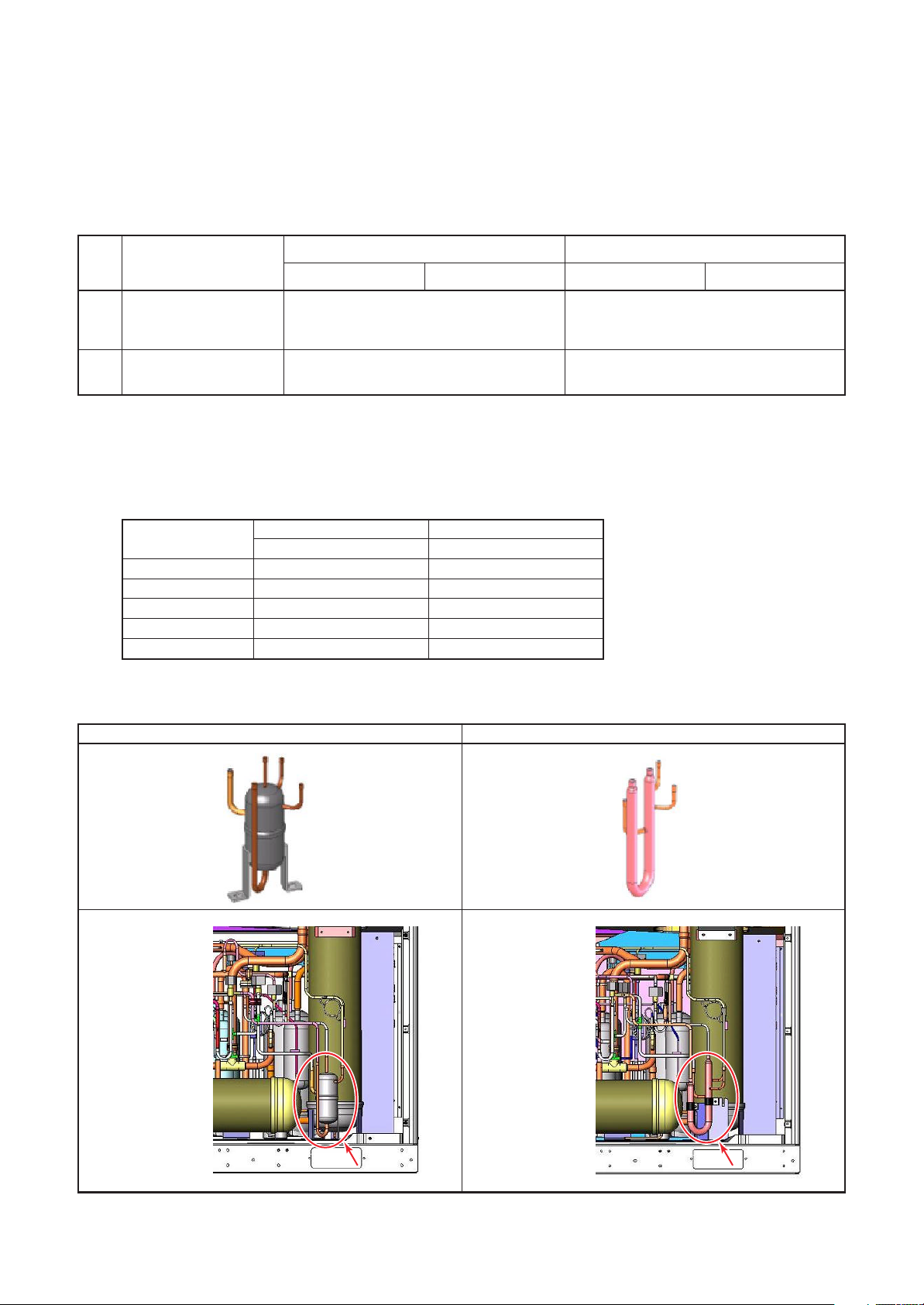
2) Change of oil tank appearance
Applied models: SMMS series, SHRM series
Model in tis time
SMMS
—
—
12.0
12.0
12.0
Model in this time
SMMS SHRM
MCC-1439-06
Addition of connector
to connect the passive filter
Electrolytic capacitor (MCC-1580),
Resistance, Diode, Reactor (CH-68)
(Appearance)
(Layout)
– Rear view —
Tank type of Oil tank (past)
Tube type of Oil tank (current)
(Appearance)
(Layout)
– Rear view —
<Reference: Product Bulletin No.2007-13>
3
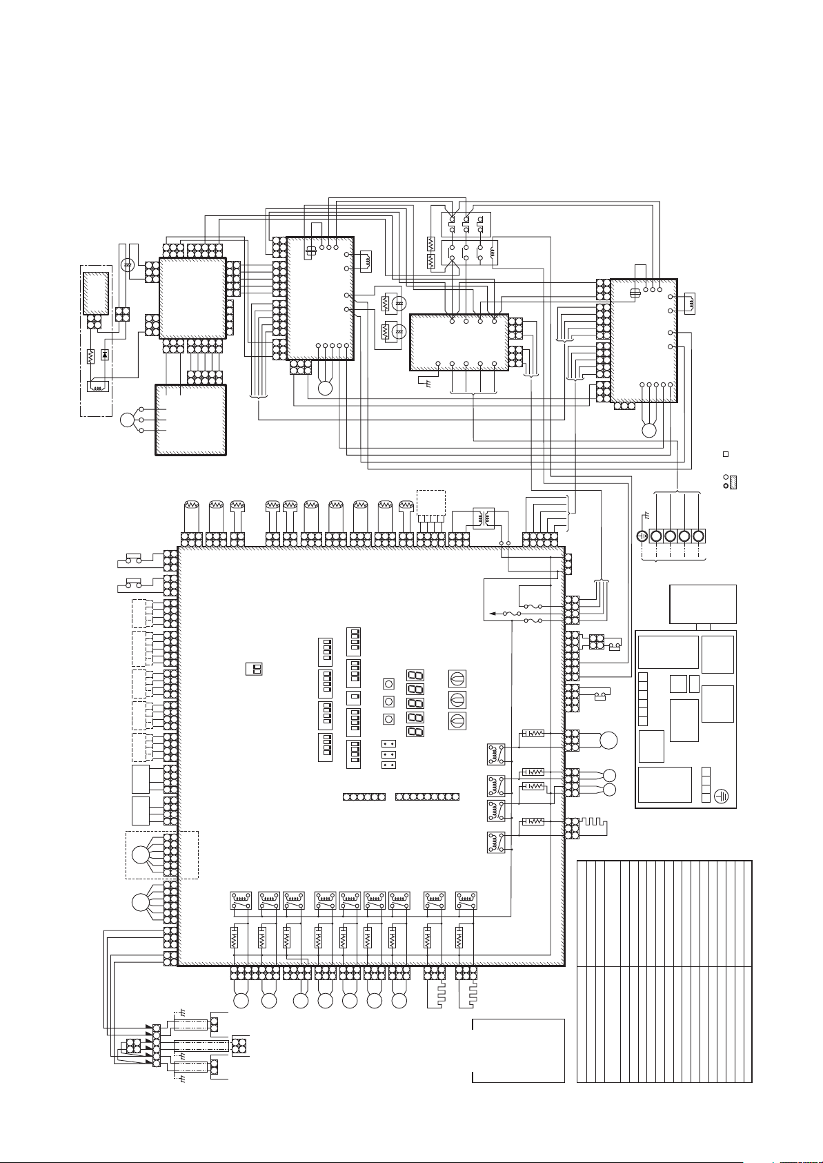
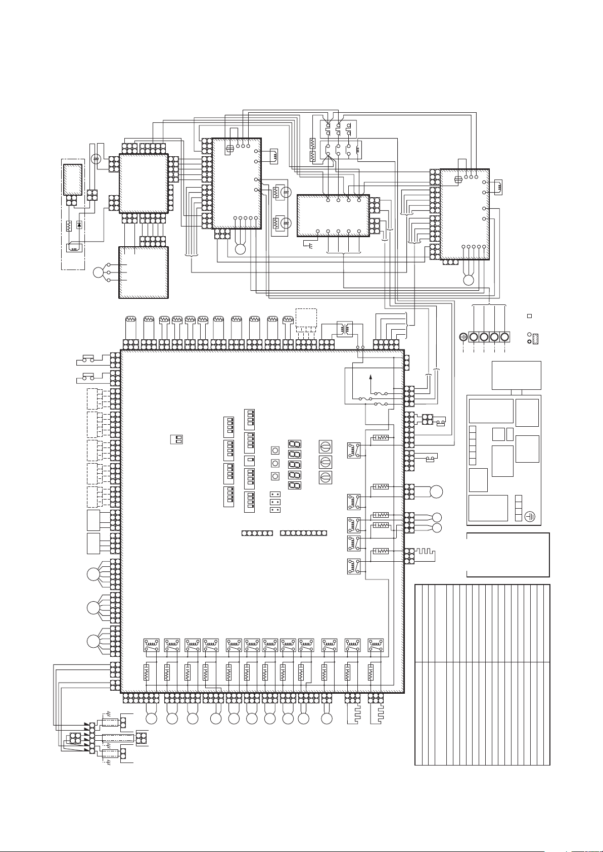
2. WIRING DIAGRAM
2-1. Outdoor Unit
Model: MMY-MAP0501HT8-E, MMY-MAP0601HT8-E, MMY-MAP0801HT8-E,
MMY-MAP1001HT8-E, MMY-MAP1201HT8-E
246
BLU
BLK
BLK
+–+–
YEL
YEL
(GRN)
TL
BLK
BLK
BLU(BLK)
1
1
2
(YEL)
CN521
SW06
SW05SW04
CN32
CN30
2
1
CN800
RY509
CR509
3
1
3
1
BLU
BLU
SV3C
CN314(BLK)
RED
PTC Themistor
P.C. board
Noise filter
BLK
(WHI)
1
122 2
(WHI)
3
CN316(WHI)
RED
246
135
Mg-SW OCR
RED
CN21
MCC-1366
board
Option
1
3
134 4
(GRN)
CN511
D603D602D601D600 D604
SW02 SW03
SW01
6
549
7
RY516
CR516
1
3
1
3
BRW
RED
RED
CN17
CN01
RED
BLU
3
3
CN100
8
1
1
Heater 1
CN315(BLU)
WHI
CN18
CN02
WHI
BLU
1
1
(BLK)
CN802
RY517
CR517
BRW
BLK
Flash
Color
A1 A2
GRY
GRY
BLK
CN19
CN03
BLK
GRY
RY521RY511
RY510
RY518
3
3
T Heater 2
indication
RED : RED
GRY
CN20
CN23(BLU)CN22(WHI)
CN04
Transformer
WHI
CN402
L1
WHI : WHITE
YEL : YELLOW
1 3
1 3
1 3
1 3
RED
CN600(WHI)
CN401
T6.3A
FUSE
BLU : BLUE
BLK : BLACK
5 5
T6.3A
FUSE
T6.3A
FUSE
CR521CR511
CR
510
CR
518
GRY : GRAY
PNK : PINK
1
3
134 4
2 2
CN305(RED)
CN307(WHI)
L3
ORN: ORANGE
BRN : BRWN
VLT : VIOLET
BLK
WHI
BLU
RED
PNK
3 1
3 1
CN17
(BLK)
PNK
RED
BLU
3 2 1
3 2
CN18
(RED)
WHI
BLK
5 4
5 4 1
PNK
RED
BLU
3 2 1
3 2
CN06
(WHI)
WHI
BLK
5 4
5 4 1
CN26
3 1
3 1
1
CN25
(WHI)
(YEL)
CN325
(WHI)
CN400
GRY
4
4
N
BLK
3
3
L3
WHI
2
21
L2
RED
1
1
L1
ORN
3 1
3 1
5 3 1 3 2 17
4 3 2 1
CN317
1 2
CN323
4
3
2
1
CN321
1 2
3
7 5
2 1
(BLU)
1 2
(WHI)
4
3
2
1
(RED)
1 2
BLK BLK
ORN
ORN
PNK
PNK
PNK
PNK
RED
BLU
BRN
ORN
BLK(PNK)
4WV1
BLK(PNK)
3E
SV
3D
SV
Accumulator
Comp1
Comp2
heater
Parts name
Compressor
Pulse motor valve
2-way valve coil
Symbol
CM1, CM2
PMV1, PMV2
SV2, SV41, SV42, SV51, SV3A,
SV3B, SV3C, SV3D, SV3E
(BLU)
Parts layout
4-way valve coil
4WV1
Passive filter
MCC-1580
CN01(WHI)
2
1
2
1
YEL
WHI YEL
RED
Reactor
BLU
+
~
BLU
+–
YEL
1
2
1
2
FM
Except 5HP, 6HP
2
1
BLU
YEL
RED
63H2
63H1
Board
Option
Board
Option
Board
Option
Board
Option
Board
Option
PD
Sensor
Pressure
PS
Sensor
Pressure
PMV2
PMV1
2
1
CN506
3
1
3
1
CN507
BLK
WHI
RED
3
3
(BLK)
3
1
CN506(BLK)
3
1
3
3
(YEL)
BLU
–
1 3
1 3
4 3 2 1
4 3 2 1
5
4 3 2 1
4 3 2 1
4 3 2 1
WHI
BLK
RED
4 3 1
WHI
BLK
RED
4 3 2
WHI
YEL
ORN
BLU
BRN
RED
6 5 4 3 2 1
WHI
YEL
ORN
BLU
BRN
RED
6 5 4 3 2 1
WHI
1
WHI
2
3
BLU
1
BLU
2
U1 U2 U3 U4 U5 U6
CN502
CN500
WVU
1 3
1 3
4 3 2 1
4
5 3 2 1
4 3 2 1
4 3 2 1
4 3 2 1
4 3 2 1
4 3 2 1
6 5 4 3 2 1
6 5 4 3 2 1
1
2
3
1
2
(BLU)
(WHI)
YEL
+
531
1
531
1
Power supply
P.C. board for FAN
54321
1
54321
1
BLK
WHI
54321
54321
FAN IPDU
P.C. Board
TD1
(YEL)
BLU(BLK)
BLU(BLK)
3
3
(BLU)
CN308
(WHI)
CN306
(BLU)
CN512
(BLU)
CN513
(WHI)
CN510
(BLK)
CN509
(RED)
CN508
(RED)
CN501
(WHI)
CN500
(WHI)
CN301
(WHI)
CN300
CN03
(WHI)
CN01
(BLU)
GRY
RED
(RED)
CN501
MCC-1439
CN504 CN505(RED)
(WHI)
CN503
BLU
RED
PNK
CN01
(WHI)
MCC-896, 897
TD2
(RED)
BLU(BLK)
BLU(BLK)
1
3
1
3
(WHI)
(PNK)
CN502
CN503
U1 U2 U5 U6
3 4
1 2 53 41 2 5
BLK
1
1
BLU
unit
Outdoor
unit
Indoor
YEL
BLU
3 4 5
1 2
TS1
(GRY)
BLK
2
1
2
1
(WHI)
CN504
ON
Interface Control P.C. Board
RY503
CR503
753
753
BLU
SV42
U3 U4
U1 U2
Central remote
3 1
3 1
BLK
WHI
BLU
3 4 5
3 4
RED
PNK
1 2
1 2 5
PNK
RED
BLU
3 2 1
3 2
WHI
BLK
5 4
5 4 1
3 1
3 1
CN25
(WHI)
TE1
(BLK)
TO
BLK
BLK
BLK
2
1
2
2
1
2
(GRN)
CN505
CN507
SW30
MCC-1429
RY502
CR502
1
432
1
BLU
BLU
SV41
CN311(BLU)
CN310(WHI)
controller
YEL
BLK
CN17
1 1
(BLK)
1
1
(YEL)
RY504
(BLK)
CN18
(RED)
CN06
(WHI)
CN26
2 2
BLU(BLK)
CR504
2
BLU
SV51
IPDU P.C. Board (1)
W
(BLU)
3 3
BLK
BLU
TK1
(BLK)
BLU(BLK)
3
3
(BLK)
CN514
1
1
BLU
BLU
CN312(WHI)
BLK
WHI
RED
T
S
R
CN03
CN02
CN01
CN13
MCC-1502
CN15
CN22
CN11
CN10
CN09
V
U
WHI
RED
YEL
CM1
TK2
(BLU)
BLU(BLK)
BLU(BLK)
1
3
1
3
(GRN)
CN515
4
31
2
SW14
ON
431
2
SW13
ON
4
31
2
SW12
ON
431
2
SW11
ON
RY506
CR506
3
1
3
1
BLU
BLU
SV2
CN324(RED)
CN23
BLU
BLU(BLK)
1
1
431
2
ON
431
2
ON
1
ON
431
2
ON
431
2
ON
RY507
3
3
SV3A
CN20
CN21
TK3
3
3
CR507
1
1
BLU
CN516
WHI
Reactor
WHI
BLU
(BLU)
BLU(BLK)
BLU(BLK)
1
1
(RED)
SW10
SW09
SW08
SW07
CN31
SW06
321
(Srvice)
RY508
CR508
3
3
BLU
SV3B
CN313(YEL)
3
3
BLU
BLK
TK4
CN523
654
1
1
BLK
WHI
RED
T
S
R
CN03
CN02
CN01
CN15 CN13
MCC-1502
IPDU Board (2)
CN22
CN23
CN11
CN10
CN09
V
U
W
3
WHI
RED
YEL
BLU
BLK
CM2
Earth screw
RED
WHI
L1L2L3
Power Supply, 3phase
380-415V 50Hz
380V 60Hz
(I/F)
control
Interface
P.C. board
U1 U2 U3 U4 U5 U6
Connecting terminal
MCC-896
Fan IPDU
P.C. board
Noise filter
MCC-1366
Compressor case thermo.
Pipe temp. sensor (Inlet)
Pipe temp. sensor (Outlet)
Heat exchange temp. sensor
Air temp. sensor
COMP1, COMP2
TS1
TD1, TD2
TE1TOTK1, TK2, TK3, TK4
CN07
WHI
Reactor
CN08
WHI
BLU
YEL
accessories sold separately and service cables, respectively.
1. The two-dot chain line indicates wiring at the local site, and the dashed line indicates
2. , , and indicate the ter minal blocks and the numerals indicate the terminal numbers.
3. indicates P.C. board.
BLK
GRY
N
filter
Passive
No.2
MCC-1429
SW
MG-
Power supply
OCR
for fan
MCC-1439
Comp. IPDU
No.1
Comp. IPDU
Power supply
MCC-1502
MCC-1502
terminal
L1 L2 L3 N
Oil temp. sensor
Liquid temp. sensor
Case heater, 230V, 26W
Fan motor (DC)
Low pressure sensor
High pressure sensor
High pressure switch
TL
HEATER1, HEATER2, ACCUMULATORFMPSPD63H1, 63H2
(Otherwise water enters into the box resulting in a trouble.)
* Be sure to fix the electric par ts cover surely with two screws.
Passive filter box
Electric parts box
Magnet switch
Overcurrent relay
MG-SW
OCR
4
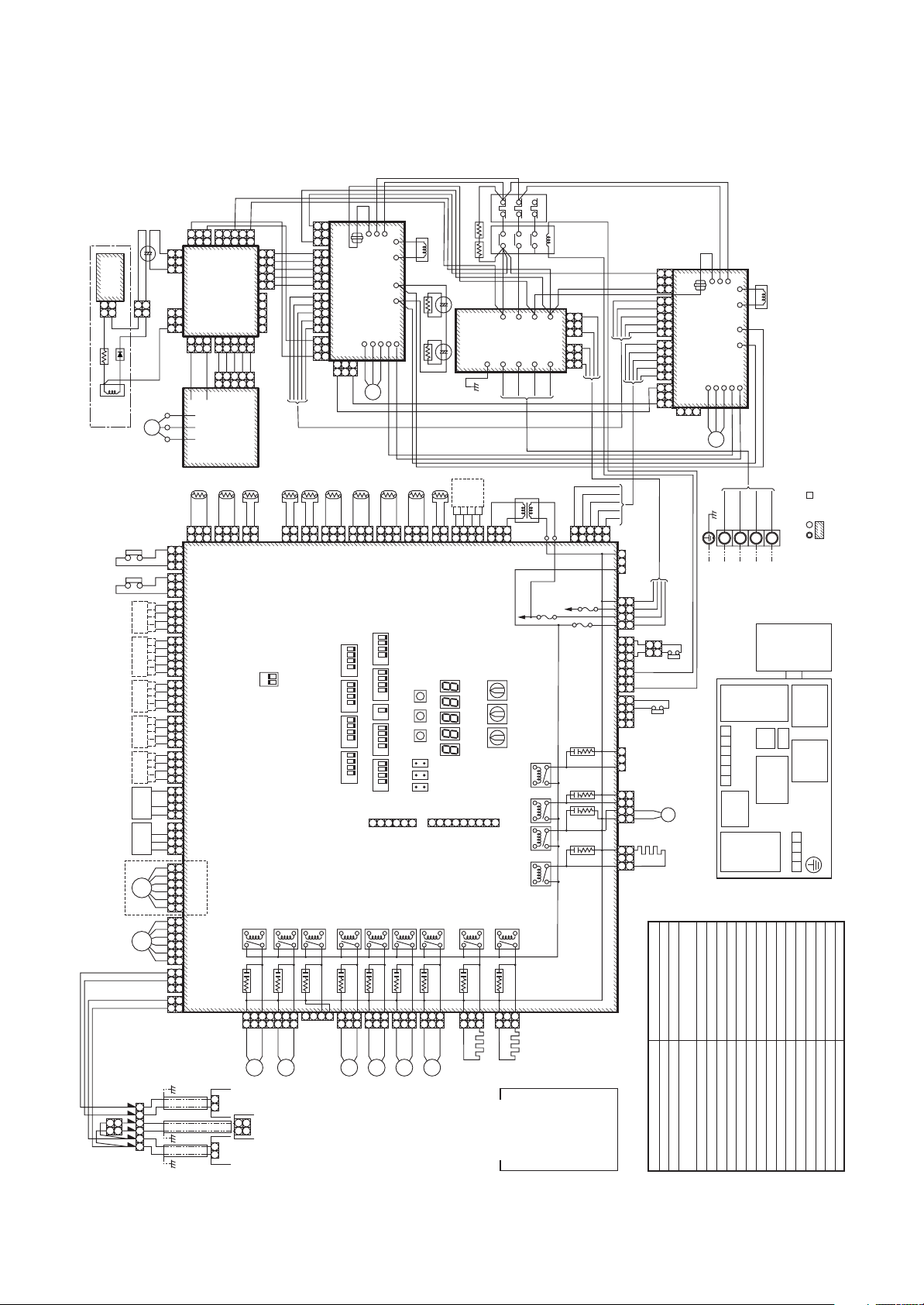
Model: MMY-MAP0501T8-E, MMY-MAP0601T8-E, MMY-MAP0801T8-E,
MMY-MAP1001T8-E, MMY-MAP1201T8-E
246
Reactor 1
BLU
BLU
BLK
BLK
YEL
YEL
RED
RED
PTC Themistor
P.C. board
Noise filter
+– +–
BLK
246
135
Mg-SW OCR
RED
RED
CN17
CN21
CN01
MCC-1366
RED
WHI
WHI
CN18
CN02
A1 A2
RED
3 1
GRY
GRY
GRY
BLK
BLK
1 3
1 3
CN19
CN20
CN23(BLU)CN22(WHI)
CN03
CN04
1 3
1 3
BLK
GRY
PNK
RED
BLU
WHI
BLK
PNK
RED
BLU
WHI
BLK
3 1
3 2
5 4 1
3 2
5 4 1
3 1
CN25
3 2 1
5 4
3 2 1
5 4
3 1
(WHI)
MCC-1580
CN01(WHI)
2
1
2
1
YEL
Passive filter
WHI YEL
RED
Reactor
BLU
+
~
BLU
+–
YEL
1
2
1
2
FM
RED
GRY
RED
531
3
1
531
3
1
BLU
(BLK)
CN506
3
3
(BLU)
CN502
1
1
YEL
3
3
1
1
3
3
(YEL)
CN507
BLU
–
BLK
WHI
RED
Power supply
P.C. board for FAN
CN500(WHI)
54321
1
54321
1
YEL
BLK
54321
54321
+
UVW
FAN IPDU
P.C. Board
(RED)
CN501
MCC-1439
(WHI)
CN503
WHI
BLU
RED
PNK
CN01
(WHI)
MCC-896, 897
CN504 CN505(RED)
RED
GRY
YEL
BLU
3 1
53 41 2 5
3 4
1 2
BLK
WHI
BLU
3 4 5
3 4
RED
PNK
1 2
1 2 5
PNK
RED
BLU
3 2
WHI
BLK
5 4 1
3 1
CN25
3 1
3 4 5
1 2
3 2 1
5 4
3 1
(WHI)
CN17
1 1
YEL
CN18
CN06
(BLK)
(RED)
(WHI)
CN26
2 2
COMP. IPDU
(BLU)
3 3
BLU
BLK
WHI
RED
L3CTL2
CN03
CN02
MCC-1502
P.C. Board (1)
CN11
CN10
CN09
V
U
W
BLK
WHI
RED
CM1
L1
CN01
YEL
CN13
CN15
CN22
CN20
WHI
CN21
WHI
BLK
CN23
BLU
CN17
CN18
CN06
1
(BLK)
(RED)
(WHI)
CN26
(BLU)
COMP. IPDU
P.C. Board (2)
W
3
BLK
BLK
CN11
WHI
RED
L3CTL2
L1
CN03
CN02
CN01
CN15 CN13
MCC-1502
CN22
CN23
CN10
CN09
V
U
WHI
RED
YEL
BLU
CM2
CN07
CN08
YEL
WHI
Reactor 2
WHI
BLU
5 5
T6.3A
CR
CR
PNK : PINK
T6.3A
FUSE
CR521CR511
510
518
BLK
WHI
BLU
RED
PNK
1
2 2
3
134 4
FUSE
CN305(RED)
CN307(WHI)
(BLU)
CN317
(WHI)
CN323
N
ORN : ORANGE
BRN : BRWN
VLT : VIOLET
CN400
4
3
2
1
5 3 1 3 2 17
4 3 2 1
1 2
432
1
CN321
1 2
CN325
(WHI)
43
3
21
1
7 5
2 1
2
1
(RED)
1 2
(YEL)
GRY
BLK
WHI
RED
BLK BLK
ORN
ORN
Earth screw
N
L3
L2
L1
ORN
3 1
3 1
COMP.1
ORN
RED
BLU
COMP.2
SV
3D
Accumulator
Parts layout
heater
BLU
BLU
BRN
Parts name
Compressor
Pulse motor valve
2-way valve coil
4-way valve coil
Compressor case thermo.
Symbol
CM1, CM2
PMV1, PMV2
SV2, SV41, SV42, SV51, SV3A,
SV3B, SV3C, SV3D, SV3E
4WV1
COMP1, COMP2
RED
WHI
BLK
GRY
L1L2L3
Pipe temp. sensor (Inlet)
TS1
N
3phase
Power Supply
380-415V 50Hz
(I/F)
control
Interface
P.C. board
MCC-1429
SW
MG-
U1 U2 U3 U4 U5 U6
Connecting terminal
for fan
MCC-1439
Power supply
MCC-896
Fan IPDU
P.C. board
Noise filter
MCC-1366
Pipe temp. sensor (Outlet)
Heat exchange temp. sensor
Air temp. sensor
Oil temp. sensor
Liquid temp. sensor
Case heater, 230V, 26W
TD1, TD2
TE1TOTK1, TK2, TK3, TK4
TL
HEATER1, HEATER2, ACCUMULATORFMPSPD63H1, 63H2
(Otherwise water enters into the box resulting in a trouble.)
accessories sold separately and service cables, respectively.
* Be sure to fix the electric par ts cover surely with two screws.
1. The two-dot chain line indicates wiring at the local site, and the dashed line indicates
2. , , and indicate the terminal blocks and the numerals indicate the terminal numbers.
3. indicates P.C. board.
filter
Passive
Passive filter box
No.2
MCC-1502
Comp. IPDU
OCR
No.1
MCC-1502
Comp. IPDU
Electric parts box
terminal
Power supply
L1 L2 L3 N
Fan motor (DC)
Low pressure sensor
High pressure sensor
High pressure switch
Magnet switch
Overcurrent relay
MG-SW
OCR
TK4
TE1
(BLU)
TO
BLK
BLK
2
2
(GRN)
CN505
SW30
RY502
CR502
BLU
BLU
SV41
CN311(BLU)
(BLK)
TK1
(BLK)
TK2
(BLU)
BLK
BLK
BLU(BLK)
BLU(BLK)
BLU(BLK)
3
3
(BLK)
CN514
1
BLU
CN312(WHI)
1
1
3
3
4
31
2
ON
431
2
ON
4
31
2
ON
431
2
ON
3
3
RY506
CR506
BLU
SV2
CN515
1
1
BLU(BLK)
1
1
(GRN)
SW14
SW13
SW12
SW11
3
3
BLU
CN324(RED)
1
2
1
1
2
1
(YEL)
CN507
RY504
CR504
1
432
1
TD1
(YEL)
TD2
(RED)
TS1
(GRY)
BLU(BLK)
BLU(BLK)
BLU(BLK)
BLU(BLK)
BLK
BLK
2
(WHI)
U1 U2 U5 U6
3
3
CN503
(PNK)
unit
Outdoor
unit
Indoor
1
1
Interface Control P.C. Board
BLU
U1 U2
1
2
1
(WHI)
CN504
ON
MCC-1429
RY503
CR503
753
753
BLU
SV42
U3 U4
controller
Central remote
3
1
3
1
63H2
63H1
Board
Option
Board
Option
Board
Option
Board
Option
Board
Option
PD
Sensor
Pressure
PS
Sensor
Pressure
PMV2
Except 5HP, 6HP
PMV1
2
2
1
1
U1 U2 U3 U4 U5 U6
WHI
BLK
RED
WHI
BLK
RED
WHI
YEL
ORN
BLU
BRN
RED
WHI
YEL
ORN
BLU
BRN
RED
WHI
WHI
BLU
BLU
(BLU)
1 3
1 3
CN308
CN502
(WHI)
1 3
1 3
CN306
(BLU)
CN512
4 3 2 1
4 3 2 1
(BLU)
4 3 2 1
4
CN513
5
5 3 2 1
(WHI)
CN510
4 3 2 1
4 3 2 1
(BLK)
CN509
4 3 2 1
4 3 2 1
(RED)
CN508
4 3 2 1
4 3 2 1
(RED)
CN501
4 3 1
4 3 2 1
(WHI)
CN500
4 3 2
4 3 2 1
(WHI)
CN301
6 5 4 3 2 1
6 5 4 3 2 1
(WHI)
CN300
6 5 4 3 2 1
6 5 4 3 2 1
1
1
2
2
CN03
(WHI)
3
3
1
1
CN01
(BLU)
2
2
TK3
BLU(BLK)
3
3
CN516
431
2
ON
431
2
ON
1
ON
431
2
ON
431
2
ON
2
1
RY507
CR507
1
1
BLU
SV3A
(WHI)
BLU(BLK)
BLU(BLK)
1
3
1
3
(RED)
SW10
SW09
SW08
SW07
SW06
SW31
543
(Service)
RY508
CR508
3
3
BLU
BLU
SV3B
CN313(YEL)
(GRN)
BLU(BLK)
1
1
(YEL)
CN523
6
CN800
1
3
1
3
BLU
CN314(BLK)
BLK
SW06
SW05SW04
SW32
SW30
1
RY509
CR509
SV3C
TL
(WHI)
BLK
1
2
122 2
(WHI)
CN521
2
1
1
BLU
3
CN316(WHI)
board
Option
1
3
134 4
(GRN)
CN511
D603D602D601D600 D604
SW02 SW03
SW01
6
549
7
RY516
CR516
1
3
1
3
BRN
BLU
3
3
CN100
8
1
1
Heater 1
CN315(BLU)
Color
BLU
1
1
(BLK)
RY521RY511
Flash
CN802
RY510
RY518
RY517
CR517
3
3
BRN
Heater 2
indication
RED : RED
WHI : WHITE
Transformer
RED
WHI
CN402
CN401
T6.3A
FUSE
L1
YEL : YELLOW
BLU : BLUE
BLK : BLACK
CN600(WHI)
GRY : GRAY
5
Model: MMY-MAP0802FT8-E, MMY-MAP1002FT8-E, MMY-MAP1202FT8-E
246
Reactor
BLU
BLK
BLK
+– +–
YEL
YEL
PTC Themistor
HVC1 HVC2
Noise filter
BLK
RED
RED
Mg-SW OCR
CN21
P.C. board
MCC-1366
246
135
RED
RED
CN17
CN01
RED
WHI
WHI
CN18
CN02
A1 A2
RED
3 1
3 1
CN17
GRY
GRY
GRY
BLK
BLK
1 3
1 3
CN19
CN20
CN23(BLU)CN22(WHI)
CN03
CN04
1 3
1 3
BLK
GRY
PNK
RED
BLU
WHI
BLK
PNK
RED
BLU
WHI
BLK
3 2
5 4 1
3 2
5 4 1
3 1
CN25
3 2 1
5 4
3 2 1
5 4
3 1
(WHI)
CN18
CN06
1
CN26
(BLK)
(RED)
(WHI)
(BLU)
3
Passive filter
MCC-1580
CN01(WHI)
2
1
2
1
YEL
RED
Reactor
+
~
WHI YEL
BLU
2
2
BLU
BLU
+–
YEL
YEL
1
1
RED
FM
(BLK)
CN506
3
1
3
1
(YEL)
CN507
3
1
3
1
BLK
WHI
RED
3
3
(BLU)
CN502
CN500(WHI)
3
3
BLU
–
UVW
1
1
Power supply
P.C. board for FAN
1
1
YEL
BLK
+
FAN IPDU
GRY
531
531
CN501
MCC-1439
(WHI)
CN503
54321
54321
WHI
BLU
RED
54321
54321
CN01
P.C. Board
MCC-896, 897
RED
(RED)
CN504 CN505(RED)
PNK
(WHI)
RED
YEL
BLU
3 1
BLK
WHI
BLU
3 4
3 4 5
3 4
RED
PNK
1 2 5
1 2
1 2 53 41 2 5
PNK
RED
BLU
3 2
WHI
BLK
5 4 1
3 1
CN25
3 1
3 4 5
1 2
3 2 1
5 4
3 1
(WHI)
YEL
CN17
CN18
CN06
1 1
(BLK)
(RED)
(WHI)
CN26
2 2
(BLU)
BLU
3 3
IPDU P.C. Board (1)
W
BLK
BLK
WHI
RED
L1L2L3
CN03
CN02
CN01
CN13
MCC-1502
CN15
CN22
CN11
CN10
CN09
V
U
WHI
RED
YEL
CM1
CN20
WHI
CN21
WHI
BLU
BLK
CN23
BLU
BLK
WHI
L1L2L3
CN03
CN02
MCC-1502
IPDU Board (2)
CN11
CN10
V
U
W
WHI
RED
BLK
CM2
RED
CN09
CN01
CN15 CN13
CN22
YEL
BLU
CN23
CN07
CN08
YEL
WHI
Reactor
WHI
BLU
5 5
T6.3A
T6.3A
CR
CR
RY517
CR517
FUSE
FUSE
CR521 CR519CR511
510
518
1
1
Heater 2
3
2 2
BLK
WHI
BLU
RED
PNK
1
134 4
CN400
4
3
2
1
5 3 1 3 17
CN305(RED)
4 3 2 1
CN307(WHI)
(BLU)
CN317
1 3
(WHI)
CN323
4
3
2
1
(RED)
CN321
1 2
(YEL)
Option
CN325
(WHI)
GRY
4
N
BLK
3
L3
WHI
21
L2
RED
1
L1
3 1
3 1
3
BLK BLK
RED
BLU
7 5
ORN
ORN
2 1
BLU
1 3
BLU
BLU
4
BLU
3
BLU
2
BLU
1
BRN
1 2
Parts name
Compressor
Pulse motor valve
Symbol
CM1, CM2
PMV1, PMV2, PMV3
Earth screw
RED
WHI
L1L2L3
3phase
Power Supply
ORN
Comp1
ORN
Comp2
4WV1
3E
SV
3D
SV
heater
Accumulator
2-way valve coil
SV2, SV41, SV42, SV51, SV3A, SV3B,
SV3C, SV3D, SV3E, SV61, SV11, SV12
U1 U2 U3 U4 U5 U6
Parts layout
Fan IPDU
Color
indication
4-way valve coil
Compressor case thermo.
Pipe temp. sensor (Inlet)
Pipe temp. sensor (Outlet)
Heat exchange temp. sensor
4WV1
COMP1, COMP2
TS1, TS2
TD1, TD2
TE1TOTK1, TK2, TK3, TK4
Interface
Connecting terminal
MCC-896
RED : RED
Air temp. sensor
BLK
GRY
N
380-415V 50Hz
Passive
(I/F)
control
P.C. board
MCC-1429
SW
MG-
OCR
for fan
MCC-1439
Power supply
P.C. board
Noise filter
MCC-1366
WHI : WHITE
YEL : YELLOW
BLU : BLUE
BLK : BLACK
Oil temp. sensor
Liquid temp. sensor
Case heater, 230V, 26W
Fan motor (DC)
Low pressure sensor
TL
HEATER1, HEATER2, ACCUMULATORFMPSPD63H1, 63H2
(Otherwise water enters into the box resulting in malfunction.)
accessories sold separately and service wires, respectively.
* Be sure to fix the electric parts cover surely with two screws.
1. The two-dot chain line indicates wiring at the local site, and the dashed line indicates
2. , , and indicate the ter minal board and the numerals indicate the terminal numbers.
3. indicates P.C. board.
filter
Passive filter box
No.2
MCC-1502
Comp. IPDU
No.1
MCC-1502
Comp. IPDU
Electric parts box
terminal
Power supply
L1 L2 L3 N
GRY : GRAY
PNK : PINK
ORN : ORANGE
BRN : BRWN
VLT : VIOLET
High pressure sensor
High pressure switch
Magnet switch
Overcurrent relay
High voltage capacitor
MG-SW
OCR
HVC1, HVC2
TK4
TS2
TE1
(BLK)
TO
TD1
(YEL)
TD2
(RED)
TS1
(GRY)
3
3
BLU
(WHI)
U3 U4
BLU(BLK)
(PNK)
CN503
RY500
CR500
3
SV61
Central
1
1
1
1
BLU
remote
controller
BLK
BLK
2
1
2
1
(WHI)
CN504
MCC-1429
Interface Control P.C. Board
753
753
BLU
BLK
2
2
CN522
ON
RY503
CR503
SV42
BLU(BLK)
BLU(BLK)
BLU(BLK)
3
1
3
1
63H2
63H1
Board
Option
Board
Option
Board
Option
Board
Option
Board
Option
PD
Sensor
Pressure
PS
Sensor
Pressure
PMV3
PMV2
PMV1
2
2
1
1
U1 U2 U3 U4 U5 U6
WHI
BLK
RED
WHI
BLK
RED
WHI
YEL
ORN
BLU
BRN
RED
WHI
YEL
ORN
BLU
BRN
RED
WHI
YEL
ORN
BLU
BRN
RED
WHI
WHI
BLU
BLU
1 3
1 3
4 3 2 1
4 3 2 1
5
4 3 2 1
4 3 2 1
4 3 2 1
4 3 1
4 3 2
6 5 4 3 2 1
6 5 4 3 2 1
6 5 4 3 2 1
1
2
3
1
2
1 3
1 3
4 3 2 1
4
5 3 2 1
4 3 2 1
4 3 2 1
4 3 2 1
4 3 2 1
4 3 2 1
6 5 4 3 2 1
6 5 4 3 2 1
6 5 4 3 2 1
1
2
3
1
2
753
U1 U2 U5 U6
(BLU)
CN308
(WHI)
CN306
(BLU)
CN512
(BLU)
CN513
(WHI)
CN510
(BLK)
CN509
(RED)
CN508
(RED)
CN501
(WHI)
CN500
(RED)
CN302
(WHI)
CN301
(WHI)
CN300
CN03
(WHI)
CN01
(BLU)
Outdoor
Indoor
unit
unit
CN502
CN309
U1 U2
(WHI)
(BLK)
TK1
(BLK)
TK2
(BLU)
BLK
BLK
BLK
BLK
BLK
BLU(BLK)
BLU(BLK)
BLU(BLK)
BLU(BLK)
3
1
3
1
2
1
2
1
1
2
1
2
1
(BLK)
(YEL)
(GRN)
CN505
CN507
SW30
RY502
RY504
CR502
CR504
1
432
1
BLU
BLU
BLU
SV41
(WHI)
(BLU)
CN310
CN311
3
BLU
(BLK)
CN514
1
2
1
BLU
SV51
1
3
CN515
4
31
2
SW14
ON
431
2
SW13
ON
4
31
2
SW12
ON
431
2
SW11
ON
RY506
CR506
3
3
BLU
SV2
CN312(WHI)
(GRN)
1
1
BLU
1
1
TK3
(BLU)
BLU(BLK)
BLU(BLK)
3
1
3
1
(RED)
CN516
431
2
SW10
ON
431
2
SW09
ON
1
ON
SW08
431
2
SW07
ON
431
2
SW06
ON
321
(Srvice)
RY507
CR507
3
1
3
1
BLU
BLU
SV3A
CN324(RED)
(GRN)
BLU(BLK)
BLU(BLK)
3
3
(YEL)
CN523
CN31
654
CN800
RY508
CR508
3
1
3
1
BLU
BLU
SV3B
CN313(YEL)
TL
(WHI)
BLK
BLK
1
1
2
(WHI)
CN521
SW06
SW05SW04
CN32
CN30
RY509
CR509
3
3
BLU
SV3C
CN314(BLK)
1
122 2
321
1
432
1
4
BLU
BLU
CN322(WHI)
Option
3
CN511
D603D602D601D600 D604
3
BLU
SV11
board
(GRN)
65498
RY513
CR513
BLU
3
1
3
134 4
SW02 SW03
SW01
7
1
BLU
CN319(WHI)
CN100
1
1
BLU
SV12
BLU
(BLK)
CN802
RY514
CR514
3
3
1
1
Flash
Transformer
CN402
RY519RY518
RY521RY511
RY510
RY516
CR516
3
1
3
1
BRN
CN316(WHI)
RED
WHI
CN401
T6.3A
FUSE
Heater 1
CN315(BLU)
CN600(WHI)
3
3
BRN
6
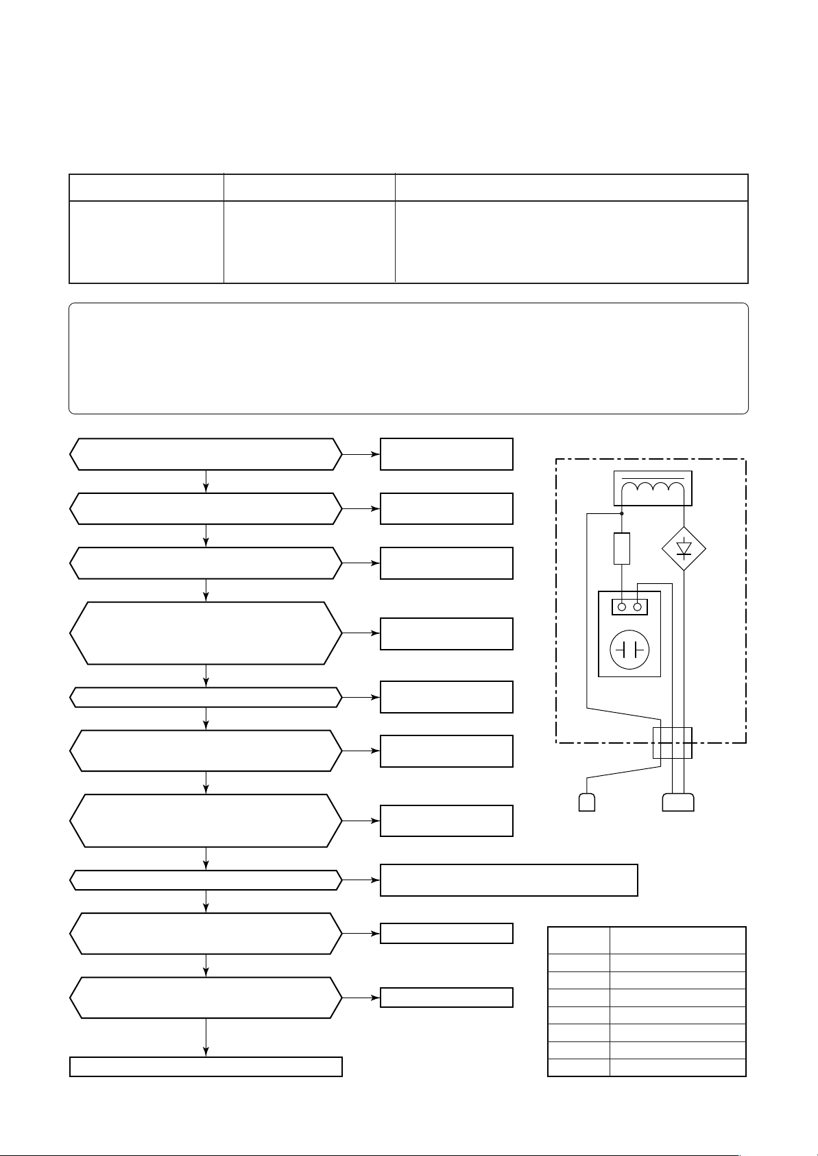
3. TROUBLESHOOTING (Passive Filter Circuit)
n Diagnosis procedure for each check code
<SMMS Series (A03-009, A04-008) >
Check code name
[L29] / [CF]
(d07 / AI-NET)
Check code name
IPDU quantity error
Cause of operation
1. Incorrect model setup in service for I/F P.C. board
2. Communication error between IPDU, fan IPDU and I/F
3. IPDU, fan IPDU, I/F P.C. board error
4. Passive filter error
Sub-code:
01: IPDU1 error 02:IPDU2 error
03: IPDU1, 2 error 04:Fan IPDU error
05: IPDU1, fan IPDU error 06:IPDU2, fan IPDU error
07: All IPDU error, Disconnection of communication line between IPDU-I/F P.C. board,
“I/F control P.C. board” error, “Power supply P.C. boad for FAN” error, “Passive filter” error
Is jumper setup of outdoor I/F P.C. board correct?
Is communication connector between IPDU
Is there no disconnection of communication line
Power supply P.C. board for FAN MCC-1439
The connector No. CN501, CN502, CN503,
Is the passive filter relay connector connected?
Power supply P.C. board for FAN normal?
Power supply P.C. board for FAN normal?
4 and 5 pins of CN600 on I/F P.C. board.
(Measurement by tester: DC0 to 5V, 5 pin GND)
3 and 5 pins of CN600 on I/F P.C. board.
(Measurement by tester: DC0 to 5V, 5 pin GND)
(Jumpers 7, 8, 9 ON)
YES
and I/F P.C. board connected?
YES
between IPDU and I/F P.C. board?
NO
Is the connector of the power supply
P.C. board connected certainly?
CN505, CN506, CN507?
YES
YES
Is the electric fuse of a
F500 10A 250V~
YES
Is the output voltage of a
CN502 or CN500 DC 330V
(Judgment : DC180-370V)
YES
Is a passive filter normal?
YES
Is there voltage fluctuation between
YES
Is there voltage fluctuation between
Both IPDU (No.1, No.2) and fan IPDU
YES
did not return the communication.
Replace IPDU P.C. board with trouble.
NO
NO
YES
NO
NO
NO
NO
NO
NO
NO
Correct connection
of connector.
Correct connection
of connector.
Replace
communication line.
Correct connection
of connector.
Correct connection
of connector.
Replace
the electric fuse.
RED BLUE YELLOW
Power supply
P.C. board error.
Check the short circuit of each part, and opening.
And correct the fault parts.
I/F P.C. board error
IPDU P.C. board error
Connector
(YELLOW)
Auxiliary
code
Passive filter box
Reactor
RED WHITE
Resistor
YELLOW
CN01
Electrolytic
capacitor board
01
02
03
04
05
06
07
IPDU 1
IPDU 2
IPDU 1, 2
Fan IPDU
IPDU 1, fan IPDU
IPDU 2, fan IPDU
IPDU 1, 2, fan IPDU, I/F
~
Diode
+
rectifier
Relay connector
(WHITE)
P.C. board
to be replaced
7
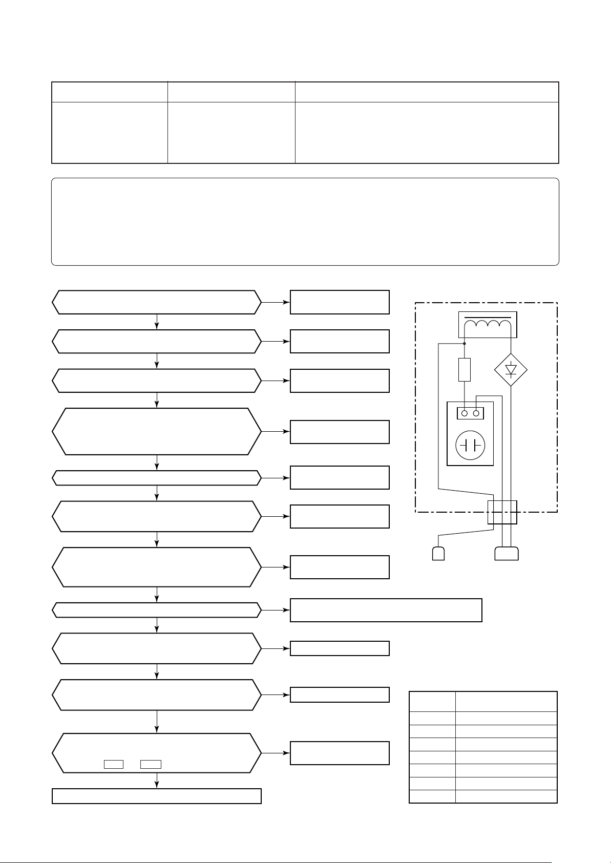
<SHRM Series (A05-004-1) >
Check code name
[L29] / [CF]
(d07 / AI-NET)
Check code name
IPDU quantity error
Cause of operation
1. Incorrect model setup in service for I/F P.C. board
2. Communication error between IPDU, fan IPDU and I/F
3. IPDU, fan IPDU, I/F P.C. board error
4. Passive filter error
Sub-code:
01: IPDU1 error 02:IPDU2 error
03: IPDU1, 2 error 04:Fan IPDU error
05: IPDU1, fan IPDU error 06:IPDU2, fan IPDU error
07: All IPDU error, Disconnection of communication line between IPDU-I/F P.C. board,
“I/F control P.C. board” error, “Power supply P.C. boad for FAN” error, “Passive filter” error
Is jumper setup of outdoor I/F P.C. board correct?
Is communication connector between IPDU
Is there no disconnection of communication line
“Power supply P.C. board for FAN MCC-1439”
The connector No. CN501, CN502, CN503,
Is the passive filter relay connector connected?
“Power supply P.C. board for FAN” normal?
“Power supply P.C. board for FAN” normal?
4 and 5 pins of CN600 on I/F P.C. board.
(Measurement by tester: DC0 to 5V, 5 pin GND)
3 and 5 pins of CN600 on I/F P.C. board.
(Measurement by tester: DC0 to 5V, 5 pin GND)
1) CN503: Between 1 and 5 pins → 12V
2) CN503: Between 2 and 5 pins → 7V
Between +5V and GND at the side of CN505: 5V
3)
Replace IPDU P.C. board with trouble.
(Jumpers 7, 8, 9 ON)
YES
and I/F P.C. board connected?
YES
between IPDU and I/F P.C. board?
NO
Is the connector of the power supply
P.C. board connected certainly?
CN505, CN506, CN507?
YES
YES
Is the electric fuse of a
F500 10A 250V~
YES
Is the output voltage of a
CN502 or CN500 DC 330V
(Judgment : DC180-370V)
YES
Is a passive filter normal?
YES
Is there voltage fluctuation between
YES
Is there voltage fluctuation between
Both IPDU (No.1, No.2) and fan IPDU
YES
did not return the communication.
On the fan power supply P.C. board,
YES
NO
NO
YES
NO
NO
NO
NO
NO
NO
NO
NO
Correct connection
of connector.
Correct connection
of connector.
Replace
communication line.
Correct connection
of connector.
Correct connection
of connector.
Replace
the electric fuse.
Power supply
P.C. board error.
Check the short circuit of each part, and opening.
And correct the fault parts.
I/F P.C. board error
IPDU P.C. board error
Replace fan power supply
on P.C. board.
RED BLUE YELLOW
Connector
(YELLOW)
Auxiliary
code
Passive filter box
Reactor
RED WHITE
Resistor
YELLOW
CN01
Electrolytic
capacitor board
01
02
03
04
05
06
07
IPDU 1
IPDU 2
IPDU 1, 2
Fan IPDU
IPDU 1, fan IPDU
IPDU 2, fan IPDU
IPDU 1, 2, fan IPDU, I/F
~
Diode
+
rectifier
Relay connector
(WHITE)
P.C. board
to be replaced
8
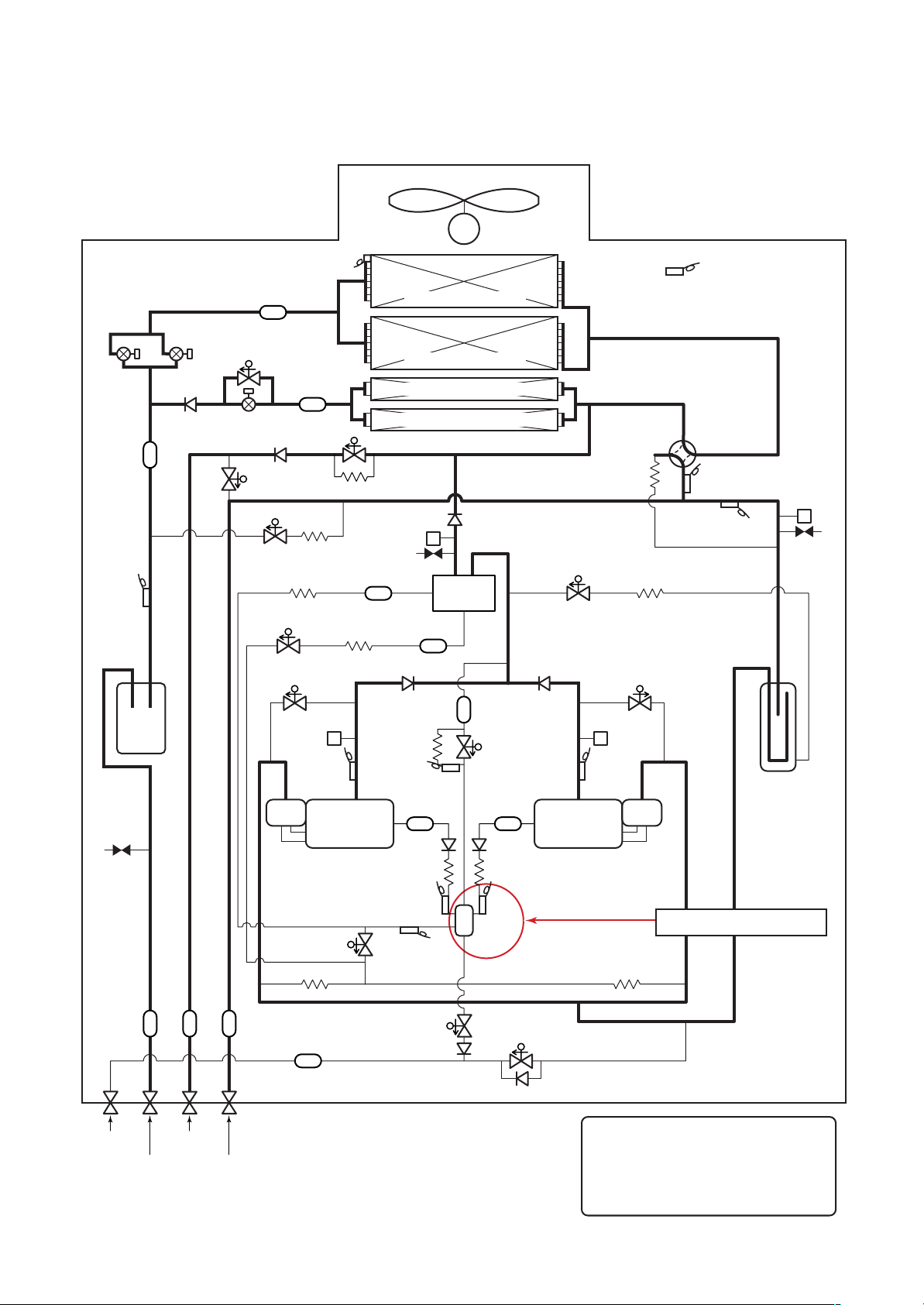
4. CONFIGURATION OF CONTROL CIRCUIT
4-1. Outdoor Unit
Power P.C. board for fan (MCC-1439)
Judgement
+12V terminal 1 – 5
( )
+7V terminal 2 – 5
Communication
between fan IPDU
DC330V output
(For Comp. IPDU)
Communication
betweenI/F and
fan IPDU
GND
+12V
CN500
DC330V output for fan IPDU
(Judgemant : DC 180–370V)
AC230V input
9
5. RUNNING CHANGE
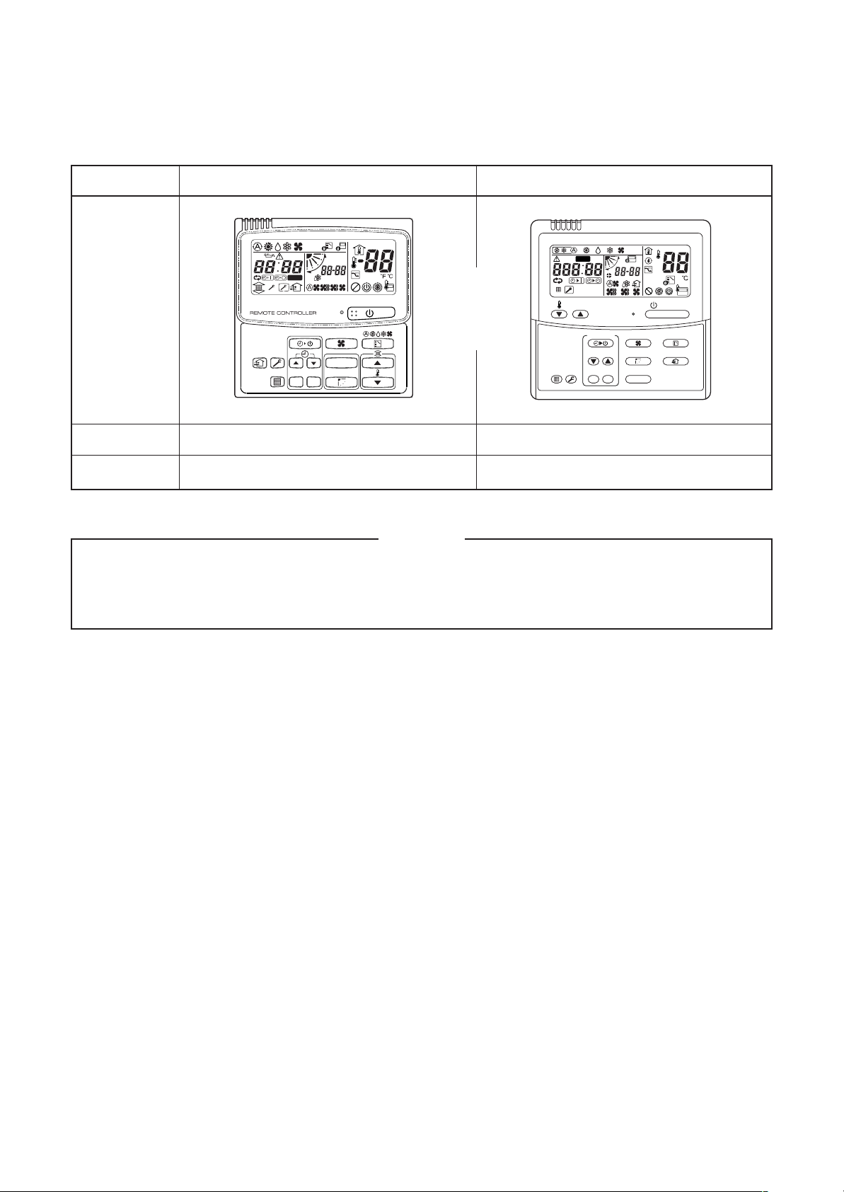
5-1. Remote Controller Switch
Name
Appearance
Model name
Wired remote controller
SET DATA
SETTING
SET
TEST
R.C. No.
CL
CODE No.
UNIT No.
UNIT
RBC-AMT21E
ð
Wired remote controller
CODE No.
ON / OFF
FAN
MODE
SWING/FIXTIME
VENT
UNITSET CL
FILTER
RESET
SET
DATA
H
TEMP.
TEST
SETTING
TEST
TIMER SET
UNIT No.
R.C. No.
RBC-AMT31E
Type
NOTE
The model name of the Wired remote controller is changed to RBC-AMT31E and some illustrations are
changed. The expression method is a little changed but functionally is not changed.
Explanation for detailed operation method, etc. are omitted.
10
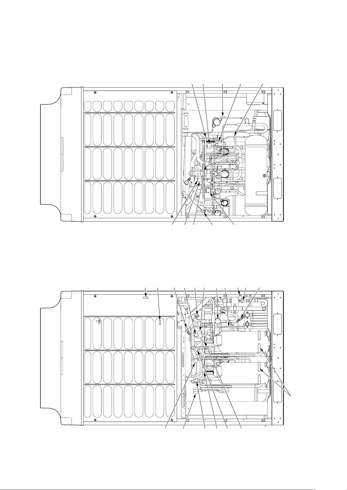
5-2. Parts Layout in Outdoor Unit
<SMMS Series (A03-009, A04-008) >
TK1, TK2
SV3E valve
SV3C valve
sensor
TK3 sensor
TK4 sensor
TE sensor
TO sensor
SV2 valve
SV3D valve
Low pressure
sensor
TS sensor
SV3A valve
Check joint
(Low pressure)
PMV
(Pulse Motor Valve)
SV5 valve
4-way valve
SV3B valve
TL sensor
High pressure
sensor
Check joint
(Liquid pipe)
Check joint
(High pressure)
Front side Rear side
Case heater
SW 1
SV42 valve
SV41 valve
High pressure
SW 2
TD1 sensor
High pressure
TD2 sensor
11
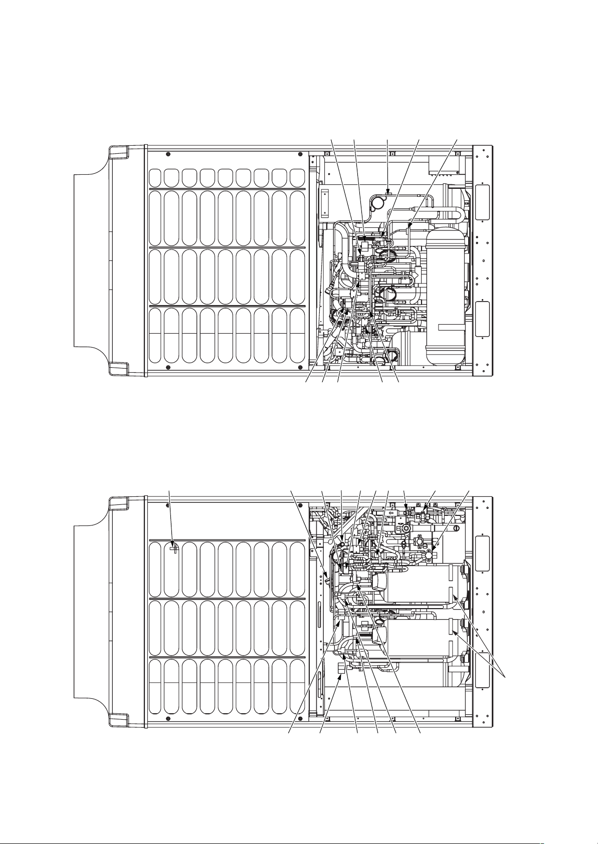
<SHRM Series (A05-004-1) >
SV3E valve
SV3C valve
SV2 valve
SV3A valve
SV3D valve
TK1, TK2 sensor
SV3B valve
TK3 sensor
TL sensor
TK4 sensor
TO sensor
Low pressure sensor
SV42 valve
Check joint
TS sensor
SV41 valve
(Low pressure)
SV5 valve
PMV
(Pulse Motor Valve)
SW 1
TD1 sensor
High pressure
4-way valve
Check joint
(High pressure)
SW 2
TD2 sensor
High pressure
Check joint
High pressure sensor
(Liquid pipe)
Front side Rear side
Case heater
12
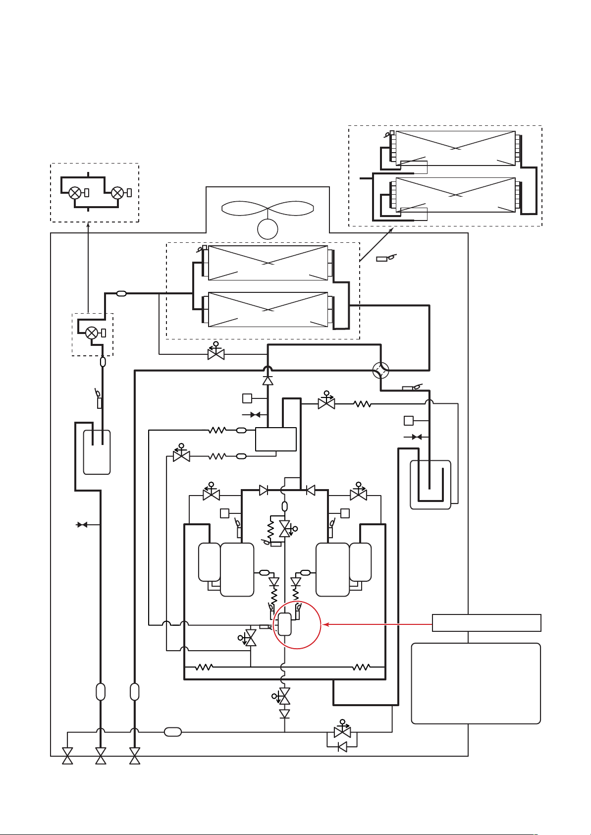
5-3. Refrigerant Piping Systematic Drawing
n Inverter unit (5, 6, 8, 10, 12HP)
Model: MMY-MAP0501HT8-E (T8-E), MMY-MAP0601HT8-E (T8-E), MMY-MAP0801HT8-E (T8-E),
MMY-MAP1001HT8-E (T8-E), MMY-MAP1201HT8-E (T8-E)
(PMV1)
Sensor
(PMV1)
(TL)
Liquid
tank
(8,10,12HP)
(PMV2)
Strainer
Pulse motor
valve (PMV)
(5,6HP)
Strainer
Sensor
(TE1)
Solenoid valve (SV5)
Capillary tube
Solenoid valve
(SV3D)
Capillary tube
Solenoid valve
(SV41)
Propeller fan
(Right side)
Air heat exchanger
at outdoor side
(Left side)
Air heat exchanger
at outdoor side
Check valve
High-pressure
sensor
Check joint
Strainer
Strainer
Check
valve
M
Fan motor
Oil
separator
4-Way valve
Solenoid valve
(SV2)
Capillary tube
Check
Solenoid valve
valve
Sensor
(TE1)
(SV42)
Sensor
(TO)
Sensor (TS1)
Low-pressure
sensor
Check joint
(Right side)
Air heat exchanger
at outdoor side
(Left side)
Air heat exchanger
at outdoor side
(8,10,12HP)
Check
joint
Balance pipe
servise valve
Liquid side
servise valve
StrainerStrainer
Gas side
servise valve
Strainer
High-pressure
switch
Sensor
(TD1)
Solenoid
valve
(SV3E)
Capillary tube
Capillary
tube
Sensor
(TK3)
Strainer
Check
(Inverter)
valve
Compressor 1
Capillary tube
Sensor
(TK1)
Sensor
(TK4)
Check
valve
Solenoid
valve
(SV3C)
Strainer
Check
valve
Capillary tube
Sensor
(TK2)
Oil tank
Solenoid
valve
(SV3A)
High-pressure
switch
Sensor
(TD2)
(Inverter)
Compressor 2
Capillary tube
Solenoid
valve
(SV3B)
Check
valve
Accumulator
Changed positions
As shown in the left, the oil
tank appearance of A03-009,
A04-008 are changed.
As there is especially no
problem in expression of the
refrigerating cycle diagram,
the diagram is not changed.
13
n Inverter unit (8, 10, 12HP)
Model: MMY-MAP0802FT8-E, MMY-MAP1002FT8-E, MMY-MAP1202FT8-E
Propeller fan
Fan motor
FM
Pulse motor valve
(PMV1) (PMV2)
Check valve
Strainer
Sensor
(TL)
Strainer
Solenoid valve
(SV12)
(PMV3)
Check valve
Solenoid valve
(SV5)
Solenoid valve
(SV6)
Capillary tube
Solenoid valve
(SV3D)
Solenoid valve
(SV41)
Sensor
(TE1)
Strainer
Capillary
tube
Capillary tube
(Right side)
Main heat exchanger
(Left side)
Main heat exchanger
Sub heat exchanger (Right side)
Sub heat exchanger (Left side)
Solenoid valve (SV11)
High-pressure
sensor
Check joint
Strainer
Strainer
Check valve Check valve
Check valve
Oil
separator
Capillary
Solenoid valve
(SV2)
Solenoid valve
Sensor
(TO)
4-Way valve
tube
Capillary tube
(SV42)
Sensor
(TS1)
Sensor
(TS2)
Low-pressure
sensor
Check
joint
Liquid
tank
Check
joint
Strainer Strainer
Service valve
of balance pipe
Service valve at
discharge gas side
Service valve
at liquid side
Service valve at
suction gas side
High-pressure
switch
Sensor
(TD1)
Compressor 1
(Inverter)
Solenoid valve
(SV3E)
Capillary tube Capillary tube
Strainer
Capillary
tube
Sensor
(TK3)
Strainer
Check
valve
Capillary tube
Sensor
(TK1)
Sensor (TK4)
Solenoid valve
(SV3A)
Check valve
Strainer
Solenoid valve
(SV3C)
Strainer
Check
valve
Capillary tube
Sensor
(TK2)
Oil tank
Solenoid valve
(SV3B)
Check valve
High-pressure
Sensor
(TD2)
Compressor 2
(Inverter)
switch
As shown in the left, the oil tank
appearance of A05-004-1 is changed.
As there is especially no problem in
expression of the refrigerating cycle
diagram, the diagram is not changed.
Accumulator
Changed positions
14

5-4. Refrigerant Recovery When Replacing the Compressor
n How to operate the system during repairing of the defective outdoor unit
MMY-MAP0501HT8(-E), MMY-MAP0601HT8(-E), MMY-MAP0801HT8(-E),
MMY-MAP1001HT8(-E), MMY-MAP1201HT8(-E)
<Work procedure>
1. Follow to the abovementioned “13-1. Refrigerant Recovery in the Troubled Outdoor Unit”.
2. Next, recover the refrigerant in the system by using a recovery device, etc.
The refrigerant amount to be recovered is determined based upon the capacity of the troubled outdoor unit.
(See the following table.)
Example) In a case of backup for 10HP-outdoor unit in 30HP system:
in the original system HP (30HP system) = 36.0kg
Refrigerant amount in system HP (20HP system) after backup = 27.0kg
Refrigerant amount to be recovered = 36.0 – 27.0 = 9kg
3. For the unit which refrigerant has been recovered, execute “Outdoor Unit Backup Setup” in another section.
All the work has finished.
System
HP
5
6
8
10
12
14
16
18
20
22
24
26
28
30
32
34
36
38
40
42
44
46
48
Combination of outdoor units
5
6
8
10
12
86
88
10 8
10 10
886
12 10
888
12 12
10 8 8
10 10 8
10 10 10
8888
12 10 10
10888
12 12 10
10 10 8 8
12 12 12
10 10 10 8
10 10 10 10
12 10 10 10
12 12 10 10
12 12 12 10
12 12 12 12
Refrigerant amount
(kg)
8.5
8.5
13.5
14.5
15.5
20.5
24.0
24.0
27.0
32.5
29.0
32.0
31.0
32.0
34.0
36.0
42.0
37.0
42.0
39.0
42.0
40.0
42.0
43.0
44.0
46.0
48.0
50.0
15

5-5. Replacing Method of Parts
<SMMS Series (A03-009, A04-008) >
No.
6
exchanged
Pressure
sensor
positions of
2-way valve coil
Part to be
Rear sideRear side
SV41
SV41
Work procedure
AccumulatorAccumulator
SV3C SV3A SV3D SV3B
SV3C SV3A SV3D SV3B
SV3E
SV3E
SV2
SV2
Compressor
Compressor
(1)
(1)
SV42
SV42
Compressor
Compressor
(2)
(2)
PS sensor
PS sensor
Remarks
Liquid tank
Liquid tank
Oil separator
Oil separator
SV5
SV5
7
Temperature
sensor
positions and
identification
Front sideFront side
Inverter assembly
Inverter assembly
<Front side of air conditioner>
TD1 sensor (Yellow) TD2 sensor (Red)
TD1 sensor (Yellow) TD2 sensor (Red)
PD sensor
PD sensor
TS1 sensor (Gray)
TS1 sensor (Gray)
Accumulator
Accumulator
TL sensor (White)
TL sensor (White)
Compressor (1) Compressor (2)
Compressor (1) Compressor (2)
16

No.
7
Part to be
exchanged
Temperature
sensor positions
and identification
Work procedure
<Rear side of air conditioner>
Rear side
Oil
separator
Liquid tank
TK sensor (White)
TK4 sensor
TK4 sensor
(Green)
(Green)
Accumulator
TK1 sensor (Black)
TK1 sensor (Black)
Accumulator side
Accumulator side
(Rear side)
(Rear side)
TK2 sensor (Blue)
TK2 sensor (Blue)
Front side
Front side
Remarks
8
Attachment/
detachment of
pipe fixing rubber
Front side
In this air conditioner, (segmentation system) eyeglass rubber
and SUS fix band are adopted for fixing the vibration system as
one measures to improve the reliability.
<Used positions of SUS fixing band: Total 5 positions>
MAP1201H, 1001H, 0801H: Ø8.0 ↔ Ø25.4
MAP1201H, 1001H, 0801H: Ø8.0 ↔ Ø25.4
MAP0601H, 0501H: Ø8.0 ↔ Ø19.05
MAP0601H, 0501H: Ø8.0 ↔ Ø19.05
between SE3E valve and suction pipe
between SE3E valve and suction pipe
Ø6.35 ↔ Ø15.88 between
Ø6.35 ↔ Ø15.88 between
SV3C valve and discharge pipe
SV3C valve and discharge pipe
Ø8.0 ↔ Ø19.05 between
Ø8.0 ↔ Ø19.05 between
SV42 valve and suction pipe
Ø8.0 ↔ Ø19.05 between
Ø8.0 ↔ Ø19.05 between
SV41 valve and suction pipe
SV41 valve and suction pipe
SV42 valve and suction pipe
17
Ø6.35 ↔ Ø15.88 between
Ø6.35 ↔ Ø15.88 between
SV2 valve and discharge pipe
SV2 valve and discharge pipe

<SHRM Series (A05-004-1) >
No.
6
exchanged
Pressure
sensor
positions of
2-way valve coil
Part to be
Rear sideRear side
SV41
SV41
Work procedure
Accumulator
Accumulator
SV3C SV3A SV3D SV3B
SV3C SV3A SV3D SV3B
SV3E
SV3E
SV2
SV2
Compressor
Compressor
(1)
(1)
SV42
SV42
Compressor
Compressor
(2)
(2)
PS sensor
PS sensor
Remarks
Liquid tank
Liquid tank
Oil separator
Oil separator
SV5
SV5
7
Temperature
sensor
positions and
identification
Front sideFront side
Inverter assembly
Inverter assembly
<Front side of air conditioner>
Front side
TD1 sensor(Yellow)
TS2 sensor
TD2 sensor(Red)
PD sensor
PD sensor
TS1 sensor(Grasy)
Accumulator
Compressor(1)
Compressor(2)
18

No.
7
exchanged
Temperature
sensor positions
and identification
Part to be
Work procedure
<Rear side of air conditioner>
Rear side
Liquid tank
TK3 sensor(White)
Remarks
TK1 sensor(Black)
Accumulator side (Front side)
Accumulator
8
Attachment/
detachment of
pipe fixing rubber
Oil separator
TK4 sensor (Green) TK2 sensor (Blue)
(Rear side)
This air conditioner has been designed so that vibration has been reduced to a minium by
incorporating in the lower section of the unit, the use of eyeglass rubber fixing brackets and
SUS bands. Both of which greatly help to reduce vibration and improve unit reliability.
Used positions of SUS fixing band:Total 5 positions
Ø6.35 ⇔ Ø15.88 between
SV3C valve and discharge pipe
Ø6.35 ⇔ Ø15.88 between
SV3E valve and suction
Ø6.35 ⇔ Ø15.88 between
SV3E valve and suction
Ø8.0 ⇔ Ø19.05 between
SV41 valve and suction pipe
19
Ø8.0 ⇔ Ø19.05 between
SV42 valve and suction pipe

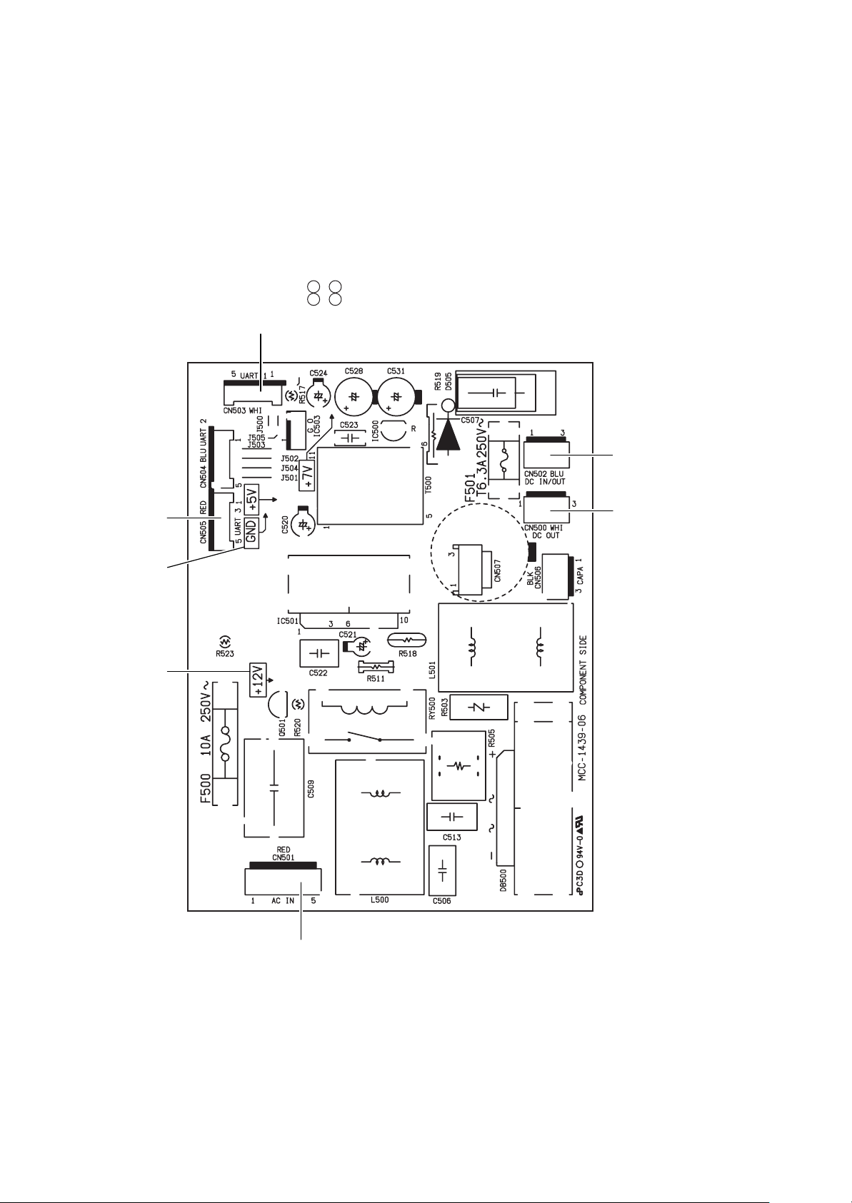
5-6. P.C. Board Exchange Procedures (Outdoor Unit)
n How to Check Fan Power Supply P.C. Board and Fan IPDU
The fan power supply P.C. board supplies DC power. It supplies DC280V for the fan IPDU, and DC12V and
DC7V for the control power supply respectively. If the control power is not supplied, a communication error
(Error code [E31]) is out.
1. How to check fan power supply P.C. board (MCC-1439)
As shown in the following table, measure the voltage of the check positions with a digital tester.
No.
1
2
3
Check item
DC280V output
Control power voltage
Check position
Between CN500 and
Between CN500 and
Between CN500 and
Criteria
DC260 to DC340V
DC12V
DC7V
2. How to check fan IPDU
1. Check that the lead wires are correctly inserted into 250 fasten terminal of DC280V input and into the
communication connector (CN01).
2. After then replace the fan IPDU if an abnormality is recognized.
<MCC-1439 Front View>
CN503
CN500
20

6. DETACHMENTS (Passive Filter Circuit)
No.
10
Part name
Passive filter
Work procedure
CAUTION
Wear protective clothing on your hands as
other components may cause injury etc.
WARNING
Never open the cabinet while 5 minutes after
turn off the power supply.
<Disassembling>
1) Stop unit operation and turn off power suplly to
unit.
2) Remove Front panel. (Screw M5 × 10 , 7pcs)
3) Remove cover of the electric parts box.
(Screw M4 × 10 , 2 pcs)
4) Open connector(CN507,yellow) of “Power
supply P.C. board for FAN”, and open relay
connector (white). <Fig.1>
5) Pssive filter wiring is fixed at 3 places.
Remove the fixation shown in the “Fig.2”.
(Binding band, 2 pcs. Wire clamp, 1pc) <Fig.2>
Remarks
<Fig.1>
CN507 of
“Power supply P.C. board for FAN”
Relay connector Passive filter wiring
<Fig.2>
Binding band (B)
6) Remove screws fixing the electric parts box.
(1 pc. each at upper and lower sides.)
7) Push down lightly the fixing claw at lower side
to take off the claw.
(Lower part of the box is out forward.) <Fig.3>
8) Take off hooking claw at upper side while
holding the ceiling board with both hands.
<Fig.4>
Binding band (A) Wire clamp
<Fig.3>
M5 screws
(2 positions)
Claw for
temporary
hooking
<Fig.4>
Hooks
21

No.
10
Part name
Passive filter
(Continued)
Work procedure
9) Remove rear panel. (Screw M5 × 10 , 7pcs)
10) Remove the screw which is fixing the passive
filter box. (Screw M4 × 10 , 2 pcs) <Fig.6>
11) Take out the passive filter box outside. <Fig.7>
12) Remove The lid of the passive filter box.
(Screw M4 × 10 , 4pcs) <Fig.8>
<Fig.7> <Fig.8>
Remarks
<Fig.6>
13) Check the short circuit of each part, and
opening. And correct the fault parts.
<Fig.9> <Fig.10>
Passive filter box
Reactor
RED WHITE
Resistor
CN01
Electrolytic
capacitor board
YELLOW
~
Diode
+
rectifier
RED BLUE YELLOW
Connector
(YELLOW)
Relay connector
(WHITE)
22

No.
10
Part name
Passive filter
(Continued)
Work procedure
<Assembly>
Assembling by contrary procedure of above
10) → 12).
Is connector of the power supply P.C. board for
fan connected?
Connector No.: CN501, CN502, CN503,
CN505, CN506, CN507
Power supply P.C. board A’SSY for Fan:
MCC-1439
Is the passive filter connector connected?
<Fig. 9> (DC260 to DC340V)
Notice
When a box fixed, it hooks on the hook of
base. <Fig.11>
<Fig.11>
Hooks
Remarks
Box
Base
23

7. EXPLODED VIEWS AND PARTS LIST
7-1. Outdoor Unit
MMY-MAP0501HT8-E (5HP), MMY-MAP0601HT8-E (6HP), MMY-MAP0801HT8-E (8HP),
MMY-MAP1001HT8-E (10HP), MMY-MAP1201HT8-E (12HP)
17
16
92
64 (8, 10, 12,HP)
or
66 (5, 6HP)
95
26
52
73
74
25
65 (8, 10, 12HP)
or
67 (5, 6HP)
93
97
49
94
96
31, 36
(5, 6HP)
or
31, 34
(8, 10, 12HP)
32
27
4 (8, 10, 12HP)
5 (5, 6HP)
91
40, 41
44
46
30
or
44
24
39
50
69
30
81
8
80
7
724
SV3A
SV3B
29
1
29
43
722
723
721

Location
No.
1 43146737 Valve, Checked, YCV5P-33GME-1
4 43041781 Compressor, DA421A3FB-23M
5 43041782 Compressor, DA351A3FB-23M
7 43046442 Valve, Packed, 9.52 DIA
8 43146680 Valve, Packed, 12.7
16 43100265 Cabinet, Up
17 43119466 Guard, Fan
25 43120219 Fan, Propeller, DIA 710, ASG
26 4312C004 Motor, Fan, DC280V, MF-230-600-1R
27 43146715 Valve, Checked, BCV-804DY
29 43146736 Valve, Checked, YCV3-22GME-1
30 43146676 Joint, Check
31 43146722 Coil, Solenoid, STF-01AJ502E1
32 43146727 Valve, Gas, DIA 25
34 43146698 Valve, 4-Way, STF-0731G
36 43146687 Valve, 4-Way, STF-0401G
39 43146734 Valve, Check, ZGV-S55B-A
40 43146709 Valve, PMV, HAM-BD24TF-1
41 43146708 Coil, PMV, HAM-MD12TF-3
43 4314Q060 Strainer, DIA 12.7, C1220T-H
44 4314Q056 Strainer, DIA 25.4, C1220T-H
46 4314Q052 Strainer, DIA 45, C1220T-H
49 43148202 Tank, Liquid
50 43148192 Separator
63 43149325 Band, Fix, SUS304
64 4314G264 Condenser Assembly, Three Row
65 4314G265 Condenser Assembly, Three Row
66 4314G249 Condenser Assembly, One Row
67 4314G250 Condenser Assembly, One Row
69 43157276 Heater, Case, 29W, AC240V
73 43197175 Nut, Flange, M10, SWCH12R
74 43197176 Washer, SPHC
80 4314Q055 Strainer, DIA 19.05, C1220T-H
81 4314Q057 Strainer, DIA 25.4, C1220T-H
91 43100396 Panel, CGCD2-Z08-C77
92 43100406 Cabinet Assembly, Front, Up
93 43100407 Cabinet Assembly, Back, Up
94 43100408 Cabinet Assembly, Side, Right
95 43100409 Cabinet Assembly, Side, Left
96 43100410 Cabinet Assembly, Front, Down
97 43100411 Cabinet Assembly, Back, Down
721 43031110 Diode, 25A, 600V, *GBPC-2506
722 43155214 Resistor, 1Ω, 20W
723 43158207 Reactor, CH-68
724 4316V362 P.C. Board Assembly, Passive, MCC-1580
Part No. Description
Model Name MMY- MAP
1201HT8-E 1001HT8-E 0801HT8-E 0601HT8-E 0501HT8-E
11111
222
22
11122
111
11111
11111
11111
11111
22222
33333
33333
11111
111
111
11
11111
22211
22211
22222
222
111
11111
11111
44444
111
111
11
11
33333
11111
11111
11111
111
11111
11111
11111
11111
11111
11111
11111
11111
11111
11111
11111
25

MMY-MAP0501HT8-E (5HP), MMY-MAP0601HT8-E (6HP), MMY-MAP0801HT8-E (8HP),
MMY-MAP1001HT8-E (10HP), MMY-MAP1201HT8-E (12HP)
52
56, 58, 63
28, 37
(SV4)
28, 33 (SV3C)
28, 33 (SV3E)
12
28, 33 (SV3A)
28, 33 (SV2)
55, 58, 63
28, 33 (SV3D)
28, 38 (SV3B)
61
49
50
57, 59, 63
54
53
68
4 (8, 10, 12HP)
or
5 (5, 6HP)
62, 72
13, 14
26
40, 41
31, 36 (5, 6HP)
31, 34
or
28, 37
30
30
32 or 35 (5, 6HP)

Location
No.
4 43041781 Compressor, DA421A3FB-23M
5 43041782 Compressor, DA351A3FB-23M
12 43049683 Band, DIA 8, EPDM
13 43050407 Thermostat, Bimetal
14 43063317 Holder, Thermostat
28 43146660
30 43146676 Joint, Check
31 43146722 Coil, Solenoid, STF-01AJ502E1
32 43146727 Valve, Gas, DIA 25
33 43146711 Valve, 2-Way, VPV-122DQ1
34 43146698 Valve, 4-Way, STF-0731G
35 43146699 Valve, Ball, B5/8F, Rohs
36 43146687 Valve, 4-Way, STF-0401G
37 43146712 Valve, 2-Way, VPV-303DQ1
38 43146730 Valve, 2-Way, VPV-603DQ2
40 43146709 Valve, PMV, HAM-BD24TF-1
41 43146708 Coil, PMV, HAM-MD12TF-3
49 43148202 Tank, Liquid
50 43148192 Separator
52 43148200 Accumulator, 20L
53 43149377 Sensor Assembly, Low Pressure, 150XA4-L1
54 43149378 Sensor Assembly, High Pressure, 150XA4-H3
55 43149317 Rubber, Supporter, Pipe, DIA 25.4
56 43149318 Rubber, Supporter, Pipe, DIA 19.0
57 43149319 Rubber, Supporter, Pipe, DIA 15.9
58 43149320 Rubber, Supporter, Pipe, DIA 8.0
59 43149321 Rubber, Supporter, Pipe, DIA 6.4
61 43149323 Rubber, Supporter, Pipe, DIA 9.52–12.7
62 43149324 Rubber, Cushion, EPDM
63 43149325 Band, Fix, SUS304
68 43151283 Switch, Pressure, ACB-4UB32W
72 43197184 Bolt, Compressor, M6, SWCH18A
Part No. Description
Coil, Solenoid, AC220–240V, 50Hz,
VPV-MOAJ510B0
Model Name MMY- MAP
1201HT8-E 1001HT8-E 0801HT8-E 0601HT8-E 0501HT8-E
222
22
22222
22222
22222
99999
33333
11111
111
55555
111
11
11
33333
11111
22211
22211
11111
11111
11111
11111
11111
111
22233
11111
33333
11111
22222
66666
44444
22222
66666
27

Refrigeration Circuit Diagram
MMY-MAP0501HT8-E (5HP), MMY-MAP0601HT8-E (6HP), MMY-MAP0801HT8-E (8HP),
MMY-MAP1001HT8-E (10HP), MMY-MAP1201HT8-E (12HP)
29
27
27
or
Valve
Checked
4 (8, 10, 12HP)
High
Pressure
68
or
Valve Checked
4 (8, 10, 12HP)
High
Pressure
TD
5 (5, 6 HP)
Switch
SV42
37
TD
5 (5, 6 HP)
Switch
43
Com-
pressor
Com-
pressor
Strainer
29
Strainer
Valve
Checked
ID 1.2
× 1000 L
77
ID 1.2 × 1000 L
Valve Checked
43
77
ID 2.0 × 1000 L
10
ID 2.0
× 1000 L
10
79
33
50
or
66 (5, 6 HP)
64 (8, 10, 12HP)
TO
Condenser
or
45 (5, 6 HP)
44 (8, 10, 12HP)
68
37
SV2
Separator Oil
High Pressure
Left Side
Strainer
Strainer
79
79
Sensor
54
Strainer
Right Side
Condenser
TE
65 (8, 10, 12HP)
Pulse Motor Valve
SV41
75
ID 0.8
× 1000 L
33
SV3C
ID 1.0
× 1000 L
76
Strainer Strainer
Joint Check
30
SV5
37
or
67 (5, 6 HP)
(5, 6 HP: 1 Valve)
ID 1.0
39
Valve 4-Way
Joint Check
40
81 (8, 10, 12HP)
or
7 (5, 6 HP)
8 (8, 10, 12HP)
× 500 L
76
SV3D
Valve Checked
or
36 (5, 6 HP)
34 (8, 10, 12HP)
TS
Low Pressure
Sensor
53
30
Strainer
TL
Strainer
or
Joint
82 (5, 6 HP)
Valve Packed
Liquid Line
SV3E
33
33
Accumulator
or
49
45 (5, 6 HP)
44 (8, 10, 12HP)
Plug Fusible
FP
Tank Liquid
30
48
7
Oil Balance
Line
Check
37
1
Valve Checked
SV3B
38
52
or
46 (8, 10, 12HP)
Strainer
or
82 (5, 6 HP)
80 (8, 10, 12HP)
or
Valve Packed
35 (5, 6 HP)
32 (8, 10, 12HP)
29
SV3A
Valve Checked
47 (5, 6 HP)
Strainer
Valve Service
(5, 6 HP: Valve Ball)
Gus Line
28

Location
No.
1 43146737 Valve, Checked, YCV5P-33GME-1
4 43041781 Compressor, DA421A3FB-23M
5 43041782 Compressor, DA351A3FB-23M
7 43046442 Valve, Packed, 9.52 DIA
8 43146680 Valve, Packed, 12.7
10 43047527 Tube, Capillary, ID 2.0 × 2000L
27 43146715 Valve, Checked, BCV-804DY
29 43146736 Valve, Checked, YCV3-22GME-1
30 43146676 Joint, Check
32 43146727 Valve, Gas, DIA 25
33 43146711 Valve, 2-Way, VPV-122DQ1
34 43146698 Valve, 4-Way, STF-0731G
35 43146699 Valve, Ball, B5/8F, Rohs
36 43146687 Valve, 4-Way, STF-0401G
37 43146712 Valve, 2-Way, VPV-303DQ1
38 43146730 Valve, 2-Way, VPV-603DQ2
39 43146734 Valve, Checked, ZGV-S55B-A
40 43146709 Valve, PMV, HAM-BD24TF-1
43 4314Q060 Strainer, DIA 12.7, C1220T-H
44 4314Q056 Strainer, DIA 25.4, C1220T-H
45 4314Q058 Strainer, DIA 25.4
46 4314Q052 Strainer, DIA 45, C1220T-H
47 4314Q053 Strainer, DIA 21, C1220T-H
48 43148220 Plug, Fusible, 73 C
49 43148202 Tank, Liquid
50 43148192 Separator
52 43148200 Accumulator, 20L
53 43149377 Sensor Assembly, Low Pressure, 150XA4-L1
54 43149378 Sensor Assembly, High Pressure, 150XA4-H3
64 4314G264 Condenser Assembly, Three Row
65 4314G265 Condenser Assembly, Three Row
66 4314G249 Condenser Assembly, One Row
67 4314G250 Condenser Assembly, One Row
68 43151283 Switch, Pressure, ACB-4UB32W
75 44246235 Tube, Capillary, Bypass, 0.8 DIA
76 44246236 Tube, Capillary, Bypass, 1.0 DIA
77 44246239 Tube, Capillary, 1.2 DIA
79 4314Q054 Strainer, DIA 12.7, C1220T-H
80 4314Q055 Strainer, DIA 19.05, C1220T-H
81 4314Q057 Strainer, DIA 25.4, C1220T-H
82 4314Q059 Strainer, DIA 25.4
Part No. Description
Model Name MMY- MAP
1201HT8-E 1001HT8-E 0801HT8-E 0601HT8-E 0501HT8-E
11111
222
22
11122
111
11111
22222
33333
33333
111
55555
111
11
11
33333
11111
11111
22211
22222
222
22
111
11
11111
11111
11111
11111
11111
11111
111
111
11
11
22222
11111
11111
11111
33333
11111
111
11
29

MMY-MAP0501HT8-E (5HP), MMY-MAP0601HT8-E (6HP), MMY-MAP0801HT8-E (8HP),
MMY-MAP1001HT8-E (10HP), MMY-MAP1201HT8-E (12HP)
706
705
704
716
711
715
707
720
713
708 719 717 709
703
701
712
702
710
Location
No.
701 43050382 Sensor, TC (F6)
702 43063248 Supporter Assembly
703 43150315 Sensor, TD (F6)
704 43155176 Capacitor, 400V DC, 1500µF
705 43158186 Transformer, TT-01-03
706 43158183 Reactor, CH-44
707 43160559 Terminal Block, 4P, AC600V, 30A
708 43160548 Terminal, 6P, AC30V, 1A
709 43163017 Supporter
710 43163048 Supporter Assembly
711 4316V366
712 4316V263 P.C. Board Assembly, Interface, MCC-1429
713 4316V237
714 4316V245 P.C. Board Assembly, A3-IPDU, MCC-1502
715 4316V360 P.C. Board Assembly, Power, MCC-1439
716 43155194 Capacitor, 400V DC, 1000µF
717 43152506 Electro Magnetic Switch, FW-2S
719 43153006 PTC-Thermistor, ZPROYCE101A500
720 43155197 Resistor, 56kΩ, 15W
Part No. Description
P.C. Board Assembly, Noise-Filter,
MCC-1366
P.C. Board Assembly, Fan-IPDU,
IPDU-2D16DA1
714
Model Name MMY- MAP
1201HT8-E 1001HT8-E 0801HT8-E 0601HT8-E 0501HT8-E
44444
33333
66666
22222
11111
22222
11111
11111
22222
11111
11111
11111
11111
22222
11111
11111
11111
22222
22222
30

7-2. Outdoor Unit
MMY-MAP0501T8-E (5HP), MMY-MAP0601T8-E (6HP), MMY-MAP0801T8-E (8HP),
MMY-MAP1001T8-E (10HP), MMY-MAP1201T8-E (12HP)
17
16
92
64 (8, 10, 12,HP)
or
66 (5, 6HP)
95
26
52
73
74
25
65 (8, 10, 12HP)
or
67 (5, 6HP)
93
97
49
94
96
32
27
30
46
4 (8, 10, 12HP)
or
5 (5, 6HP)
91
40, 41
44
44
39
50
69
SV3A
30
81
8
80
7
724
SV3B
29
1
29
43
722
723
721
31

Location
No.
1 43146737 Valve, Checked, YCV5P-33GME-1
4 43041781 Compressor, DA421A3FB-23M
5 43041782 Compressor, DA351A3FB-23M
7 43046442 Valve, Packed, 9.52 DIA
8 43146680 Valve, Packed, 12.7
16 43100265 Cabinet, Up
17 43119466 Guard, Fan
25 43120219 Fan, Propeller, DIA 710, ASG
26 4312C004 Motor, Fan, DC280V, MF-230-600-1R
27 43146715 Valve, Checked, BCV-804DY
29 43146736 Valve, Checked, YCV3-22GME-1
30 43146676 Joint, Check
32 43146727 Valve, Gas, DIA 25
39 43146734 Valve, Check, ZGV-S55B-A
40 43146709 Valve, PMV, HAM-BD24TF-1
41 43146708 Coil, PMV, HAM-MD12TF-3
43 4314Q060 Strainer, DIA 12.7, C1220T-H
44 4314Q056 Strainer, DIA 25.4, C1220T-H
46 4314Q052 Strainer, DIA 45, C1220T-H
49 43148202 Tank, Liquid
50 43148192 Separator
63 43149325 Band, Fix, SUS304
64 4314G264 Condenser Assembly, Three Row
65 4314G265 Condenser Assembly, Three Row
66 4314G249 Condenser Assembly, One Row
67 4314G250 Condenser Assembly, One Row
69 43157276 Heater, Case, 29W, AC240V
73 43197175 Nut, Flange, M10, SWCH12R
74 43197176 Washer, SPHC
80 4314Q055 Strainer, DIA 19.05, C1220T-H
81 4314Q057 Strainer, DIA 25.4, C1220T-H
91 43100396 Panel, CGCD2-Z08-C77
92 43100406 Cabinet Assembly, Front, Up
93 43100407 Cabinet Assembly, Back, Up
94 43100408 Cabinet Assembly, Side, Left
95 43100409 Cabinet Assembly, Side, Right
96 43100410 Cabinet Assembly, Front, Down
97 43100411 Cabinet Assembly, Back, Down
721 43031110 Diode, 25A, 600V, *GBPC-2506
722 43155214 Resistor, 1Ω, 20W
723 43158207 Reactor, CH-68
724 4316V362 P.C. Board Assembly, Passive, MCC-1580
Part No. Description
Model Name MMY- MAP
1201T8-E 1001T8-E 0801T8-E 0601T8-E 0501T8-E
11111
222
22
11122
111
11111
11111
11111
11111
22222
33333
33333
111
11111
22211
22211
22222
222
111
11111
11111
44444
111
111
11
11
33333
11111
11111
11111
111
11111
11111
11111
11111
11111
11111
11111
11111
11111
11111
11111
32

MMY-MAP0501T8-E (5HP), MMY-MAP0601T8-E (6HP), MMY-MAP0801T8-E (8HP),
MMY-MAP1001T8-E (10HP), MMY-MAP1201T8-E (12HP)
52
56, 58, 63
28, 37
(SV4)
28, 33 (SV3C)
28, 33 (SV3E)
12
28, 33 (SV3A)
28, 33 (SV2)
55, 58, 63
28, 33 (SV3D)
28, 38 (SV3B)
61
49
50
57, 59, 63
54
53
68
4 (8, 10, 12HP)
or
5 (5, 6HP)
62, 72
13, 14
33
40, 41
30
30
32 (8, 10, 12HP)
or
35 (5, 6HP)

Location
No.
4 43041781 Compressor, DA421A3FB-23M
5 43041782 Compressor, DA351A3FB-23M
12 43049683 Band, DIA 8, EPDM
13 43050407 Thermostat, Bimetal
14 43063317 Holder, Thermostat
28 43146660
30 43146676 Joint, Check
32 43146727 Valve, Gas, DIA 25
33 43146711 Valve, 2-Way, VPV-122DQ1
35 43146699 Valve, Ball, B5/8F, Rohs
37 43146712 Valve, 2-Way, VPV-303DQ1
38 43146730 Valve, 2-Way, VPV-603DQ2
40 43146709 Valve, PMV, HAM-BD24TF-1
41 43146708 Coil, PMV, HAM-MD12TF-3
49 43148202 Tank, Liquid
50 43148192 Separator
52 43148200 Accumulator, 20L
53 43149377 Sensor Assembly, Low Pressure, 150XA4-L1
54 43149378 Sensor Assembly, High Pressure, 150XA4-H3
55 43149317 Rubber, Supporter, Pipe, DIA 25.4
56 43149318 Rubber, Supporter, Pipe, DIA 19.0
57 43149319 Rubber, Supporter, Pipe, DIA 15.9
58 43149320 Rubber, Supporter, Pipe, DIA 8.0
59 43149321 Rubber, Supporter, Pipe, DIA 6.4
61 43149323 Rubber, Supporter, Pipe, DIA 9.52–12.7
62 43149324 Rubber, Cushion, EPDM
63 43149325 Band, Fix, SUS304
68 43151283 Switch, Pressure, ACB-4UB32W
72 43197184 Bolt, Compressor, M6, SWCH18A
Part No. Description
Coil, Solenoid, AC220–240V, 50Hz,
VPV-MOAJ510B0
Model Name MMY- MAP
1201T8-E 1001T8-E 0801T8-E 0601T8-E 0501T8-E
222
22
22211
22222
22222
77777
33333
111
44444
11
22222
11111
22211
22211
11111
11111
11111
11111
11111
111
22233
11111
33333
11111
22222
66666
44444
22222
66666
34

Refrigeration Circuit Diagram
MMY-MAP0501T8-E (5HP), MMY-MAP0601T8-E (6HP), MMY-MAP0801T8-E (8HP),
MMY-MAP1001T8-E (10HP), MMY-MAP1201T8-E (12HP)
29
43
Strainer
Valve
Checked
ID 1.2
× 1000 L
Checked
or
5 (5, 6 HP)
TD
4 (8, 10, 12HP)
High
Pressure
Switch
68
SV42
or
TD
5 (5, 6 HP)
4 (8, 10, 12HP)
High
Pressure
Switch
37
Com-
pressor
Com-
Strainer
pressor
29
Valve Checked
43
77
ID 1.2 × 1000 L
77
ID 2.0 × 1000 L
10
ID 2.0
× 1000 L
10
27
Valve
Valve Checked
27
79
33
50
or
66 (5, 6 HP)
64 (8, 10, 12HP)
TO
Condenser
or
45 (5, 6 HP)
44 (8, 10, 12HP)
68
37
SV2
Separator Oil
High Pressure
Left Side
Strainer
Strainer
79
79
Sensor
54
Strainer
Right Side
Condenser
TE
65 (8, 10, 12HP)
Pulse Motor Valve
SV41
75
ID 0.8
× 1000 L
33
SV3C
ID 1.0
× 1000 L
76
Strainer Strainer
Joint Check
30
SV5
37
or
67 (5, 6 HP)
(5, 6 HP: 1 Valve)
ID 1.0
39
Joint Check
or
40
81 (8, 10, 12HP)
or
7 (5, 6 HP)
8 (8, 10, 12HP)
× 500 L
76
SV3D
Valve Checked
TS
Low Pressure
Sensor
53
30
Strainer
TL
Strainer
Joint
82 (5, 6 HP)
Valve Packed
Liquid Line
33
Accumulator
or
49
45 (5, 6 HP)
44 (8, 10, 12HP)
Plug Fusible
FP
Tank Liquid
30
48
7
Oil Balance
Line
Check
33
1
Valve Checked
SV3B
38
52
or
Strainer
80 (8, 10, 12HP)
)
Valve
Packed
or
32 (8, 10, 12HP)
29
SV3A
Valve Checked
Strainer
82 (5, 6 HP)
Valve Service
35 (5, 6 HP)
Gus Line
or
47 (5, 6 HP)
46 (8, 10, 12HP)
(5, 6 HP: Valve Ball)
35

Location
No.
1 43146737 Valve, Checked, YCV5P-33GME-1
4 43041781 Compressor, DA421A3FB-23M
5 43041782 Compressor, DA351A3FB-23M
7 43046442 Valve, Packed, 9.52 DIA
8 43146680 Valve, Packed, 12.7
10 43047527 Tube, Capillary, ID 2.0 × 2000L
27 43146715 Valve, Checked, BCV-804DY
29 43146736 Valve, Checked, YCV3-22GME-1
30 43146676 Joint, Check
32 43146727 Valve, Gas, DIA 25
33 43146711 Valve, 2-Way, VPV-122DQ1
35 43146699 Valve, Ball, B5/8F, Rohs
37 43146712 Valve, 2-Way, VPV-303DQ1
38 43146730 Valve, 2-Way, VPV-603DQ2
39 43146734 Valve, Checked, ZGV-S55B-A
40 43146709 Valve, PMV, HAM-BD24TF-1
43 4314Q060 Strainer, DIA 12.7, C1220T-H
44 4314Q056 Strainer, DIA 25.4, C1220T-H
45 4314Q058 Strainer, DIA 25.4
46 4314Q052 Strainer, DIA 45, C1220T-H
47 4314Q053 Strainer, DIA 21, C1220T-H
48 43148220 Plug, Fusible, 73°C
49 43148202 Tank, Liquid
50 43148192 Separator
52 43148200 Accumulator, 20L
53 43149377 Sensor Assembly, Low Pressure, 150XA4-L1
54 43149378 Sensor Assembly, High Pressure, 150XA4-H3
64 4314G264 Condenser Assembly, Three Row
65 4314G265 Condenser Assembly, Three Row
66 4314G249 Condenser Assembly, One Row
67 4314G250 Condenser Assembly, One Row
68 43151283 Switch, Pressure, ACB-4UB32W
75 44246235 Tube, Capillary, Bypass, 0.8 DIA
76 44246236 Tube, Capillary, Bypass, 1.0 DIA
77 44246239 Tube, Capillary, 1.2 DIA
79 4314Q054 Strainer, DIA 12.7, C1220T-H
80 4314Q055 Strainer, DIA 19.05, C1220T-H
81 4314Q057 Strainer, DIA 25.4, C1220T-H
82 4314Q059 Strainer, DIA 25.4
Part No. Description
Model Name MMY- MAP
1201T8-E 1001T8-E 0801T8-E 0601T8-E 0501T8-E
11111
222
22
11122
111
11111
22222
33333
33333
111
44444
11
22222
11111
11111
22211
22222
222
22
111
11
11111
11111
11111
11111
11111
11111
111
111
11
11
22222
11111
11111
11111
33333
11111
111
11
36

MMY-MAP0501T8-E (5HP), MMY-MAP0601T8-E (6HP), MMY-MAP0801T8-E (8HP),
MMY-MAP1001T8-E (10HP), MMY-MAP1201T8-E (12HP)
706
705
704
716
711
715
707
720
713
708 719 717 709
703
701
712
702
710
Location
No.
701 43050382 Sensor, TC (F6)
702 43063248 Supporter Assembly
703 43150315 Sensor, TD (F6)
704 43155176 Capacitor, 400V DC, 1500µF
705 43158186 Transformer, TT-01-03
706 43158183 Reactor, CH-44
707 43160559 Terminal Block, 4P, AC600V, 30A
708 43160548 Terminal, 6P, AC30V, 1A
709 43163017 Supporter
710 43163048 Supporter Assembly
711 4316V366
712 4316V263 P.C. Board Assembly, Interface, MCC-1429
713 4316V237
714 4316V245 P.C. Board Assembly, A3-IPDU, MCC-1502
715 4316V360 P.C. Board Assembly, Power, MCC-1439
716 43155194 Capacitor, 400V DC, 1000µF
717 43152506 Electro Magnetic Switch, FW-2S
719 43153006 PTC-Thermistor, ZPROYCE101A500
720 43155197 Resistor, 56kΩ, 15W
Part No. Description
P.C. Board Assembly, Noise-Filter,
MCC-1366
P.C. Board Assembly, Fan-IPDU,
IPDU-2D16DA1
714
Model Name MMY- MAP
1201T8-E 1001T8-E 0801T8-E 0601T8-E 0501T8-E
44444
33333
66666
22222
11111
22222
11111
11111
22222
11111
11111
11111
11111
22222
11111
11111
11111
22222
22222
37

7-3. Outdoor Unit
MMY-MAP0802FT8-E, MMY-MAP1002FT8-E, MMY-MAP1202FT8-E
15
63, 64
17
57
73
14
18
71
58
75
70
74
69
30, 31
4
21
25
47
46
22
34
32
60
9
6, 33
42, 43
44
21
40
724
SV3A
24
20
72
722
723
721
SV3B
28
45
19
39, 41
23
21
38
29
26, 76
35 29
38
20
36
5, 7

Location
No.
4 43041781 Compressor, DA421A3FB-23M
5 43046442 Valve, Packed, 9.52 DIA
6 43146680 Valve, Packed, 12.7
7 43047401 Bonnet, 3/8, IN
9 43063332 Holder, Sensor
14 43100265 Cabinet, Up
15 43119466 Guard, Fan
17 43120219 Fan, Propeller, DIA 710, ASG
18 4312C004 Motor, Fan, DC 280V, MF-230-600-1R
19 43146715 Valve, Checked, BCV-804DY
20 43146736 Valve, Checked, YCV3-22GME-1
21 43146676 Joint, Check
22 43146722 Coil, Solenoid, STF-01AJ502E1
23 43146727 Valve, Gas, DIA 25
24 43146711 Valve, 2-Way, VPV-122DQ1
25 43146698 Valve, 4-Way, STF-0731G
26 43146699 Valve, Ball, B5/8F, Rohs
28 43146730 Valve, 2-Way, VPV-603DQ2
29 43146734 Valve, Check, ZGV-S55B-A
30 43146709 Valve, PMV, HAM-BD24TF-1
31 43146708 Coil, PMV, HAM-MD12TF-3
32 43146731 Valve, 2-Way, VPV-1204DQ50
33 43147195 Bonnet, 1/2, IN
34 4314Q052 Strainer, DIA 45, C1220T-H
35 4314Q053 Strainer, DIA 21, C1220T-H
36 4314Q060 Strainer, DIA 12.7, C1220T-H
38 4314Q055 Strainer, DIA 19.05, C1220T-H
39 4314Q056 Strainer, DIA 25.4, C1220T-H
40 4314Q057 Strainer, DIA 25.4, C1220T-H
41 4314Q058 Strainer, DIA 25.4
42 43148220 Plug, Fusible, 73°C
43 43148202 Tank, Liquid
44 43148192 Separator
45 43146737 Valve, Checked, YCV5P-33GME-1
46 43148200 Accumulator, 20L
47 43149377 Sensor Assembly, Low Pressure, 150XA4-L1
57 4314G272 Condenser Assembly, Three Row
58 4314G273 Condenser Assembly, Three Row
60 43157276 Heater, Case, 29W, AC 240V
61 431S8087 Owner’s Manual, MMY-MAP1202FT8-E
63 43197175 Nut, Flange, M10, SWCH12R
64 43197176 Washer, SPHC
69 43100396 Panel, CGCD2-Z08-C77
70 43100406 Cabinet Assembly, Front, Up
71 43100407 Cabinet Assembly, Back, Up
72 43100408 Cabinet Assembly, Side, Left
73 43100409 Cabinet Assembly, Side, Right
74 43100410 Cabinet Assembly, Front, Down
75 43100411 Cabinet Assembly, Back, Down
76 43194029 Bonnet
721 43031110 Diode, 25A, 600V, *GBPC-2506
722 43155214 Resistor, 1Ω, 20W
723 43158207 Reactor, CH-68
724 4316V362 P.C. Board Assembly, Passive, MCC-1580
Part No. Description
Model Name MMY-MAP
1202FT8-E 1002FT8-E 0802FT8-E
222
111
111
111
111
111
111
111
111
222
333
333
111
111
777
111
111
111
222
333
333
111
111
111
111
222
111
222
111
111
111
111
111
111
111
111
111
111
333
111
111
111
111
111
111
111
111
111
111
111
111
111
111
111
39

MMY-MAP0802FT8-E, MMY-MAP1002FT8-E, MMY-MAP1202FT8-E
46
50, 52, 56
27, 65
(SV41)
27, 65
(SV42)
24, 65 (SV3C)
24, 65 (SV3E)
24, 65 (SV3A)
10
24, 65 (SV3D)
49, 52, 56
28, 65 (SV3B)
54
42, 43
54
24, 65
(SV6)
37
44
65 (SV11)
32
47
50, 53, 56
50, 53, 56
48
59
4
55, 62
12, 11
30, 31 (SV12)
25
21
27, 65 (SV5)
40

Location
No.
4 43041781 Compressor, DA421A3FB-23M
10 43049683 Band, DIA 8, EPDM
11 43050407 Thermostat, Bimetal
12 43063317 Holder, Thermostat
21 43146676 Joint, Check
24 43146711 Valve, 2-Way, VPV-122DQ1
25 43146698 Valve, 4-Way, STF-0731G
27 43146712 Valve, 2-Way, VPV-303DQ1
28 43146730 Valve, 2-Way, VPV-603DQ2
30 43146709 Valve, PMV, HAM-BD24TF-1
31 43146708 Coil, PMV, HAM-MD12TF-3
32 43146731 Valve, 2-Way, VPV-1204DQ50
37 4314Q054 Strainer, DIA 12.7, C1220T-H
42 43148220 Plug, Fusible, 73°C
43 43148202 Tank, Liquid
44 43148192 Separator
46 43148200 Accumulator, 20L
47 43149377 Sensor Assembly, Low Pressure, 150XA4-L1
48 43149378 Sensor Assembly, High Pressure, 150XA4-H3
49 43149317 Rubber, Supporter, Pipe, DIA 25.4
50 43149318 Rubber, Supporter, Pipe, DIA 19.0
52 43149320 Rubber, Supporter, Pipe, DIA 8.0
53 43149321 Rubber, Supporter, Pipe, DIA 6.4
54 43149323 Rubber, Supporter, Pipe, DIA 9.52–12.7
55 43149324 Rubber, Cushion, EPDM
56 43149325 Band, Fix, SUS304
59 43151283 Switch, Pressure, ACB-4UB32W
62 43197184 Bolt, Compressor, M6, SWCH 18A
65 43146660 Coil, Solenoid, AV 220 – 240V, 50Hz
Part No. Description
Model Name MMY-MAP
1202FT8-E 1002FT8-E 0802FT8-E
222
222
222
222
333
777
111
333
111
333
333
111
333
111
111
111
111
111
111
111
555
333
222
444
666
666
222
666
12 12 12
41

Refrigeration Circuit Diagram
MMY-MAP0802FT8-E, MMY-MAP1002FT8-E, MMY-MAP1202FT8-E
39
Strainer
30
Pulse motor valve
Solenoid valve
(PMV1) (PMV2)
Check
Strainer
39
Sensor
(TL)
Liquid
tank
valve
27
(SV12)
(PMV3)
1
Solenoid
valve
(SV5)
Solenoid
valve
(SV6)
24
42,
43
Check
joint
27
21
40
Strainer Strainer
6
35
34
26 23
5
Sensor
(TE1)
24
Strainer
41
Check
valve
29
Capillary
tube
Capillary tube
Solenoid valve
Solenoid valve
(SV41)
8
Strainer
Propeller fan
FM
Fan motor
(Right side)
Main heat exchanger
(Left side)
Main heat exchanger
Sub heat exchanger (Right side)
Sub heat exchanger (Left side)
32
Solenoid
valve
48
Check joint
(SV11)
High-pressure
sensor
21
Strainer
(SV3D)
Capillary tube
67
Strainer
59
High-
pressure
switch
Sensor
(TD1)
Compressor 1
44
20
Solenoid
valve
(SV3E)
Capillary tube
Oil
separator
Check
valve
66
19
Capillary
tube
Sensor
(TK3)
Strainer Strainer
Check
(Inverter)
valve
Capillary
tube
Sensor
(TK1)
Sensor
(TK4)
24
29
Check
valve
37
24
Oil tank
17
58
57
4-Way valve
Capillary
tube
66
Solenoid valve
(SV2)
Capillary tube
24
44
Check
valve
19
Solenoid valve
27
59
Solenoid
valve
(SV3C)
Check
valve
Capillary
tube
Sensor
(TK2)
Sensor
(TD2)
Compressor 2
68
Capillary tube
Highpressure
switch
(Inverter)
Sensor
(TO)
(SV42)
25
Sensor
(TS1)
Sensor
(TS2)
Accumulator
Lowpressure
sensor
Check
joint
46
47
21
8
Solenoid
valve
(SV3A)
20
27
Check
valve
28
Solenoid
valve
(SV3B)
Service
valve of
balance
pipe
Service
valve at
liquid
side
Service
valve at
discharge
gas side
Service
valve at
suction
gas side
38
42
45
Check
valve

Location
No.
1 43146721 Valve, Checked, BCV-603DY
4 43041781 Compressor, DA421A3FB-23M
5 43046442 Valve, Packed, 9.52 DIA
6 43146680 Valve, Packed, 12.7
8 43047527 Tube, Capillary, ID 2.0 × 2000L
17 43120219 Fan, Propeller, DIA 710, ASG
19 43146715 Valve, Checked, BCV-804DY
20 43146736 Valve, Checked, YCV3-22GME-1
21 43146676 Joint, Check
23 43146727 Valve, Gas, DIA 25
24 43146711 Valve, 2-Way, VPV-122DQ1
25 43146698 Valve, 4-Way, STF-0731G
26 43146699 Valve, Ball, B5/8F, Rohs
27 43146712 Valve, 2-Way, VPV-303DQ1
28 43146730 Valve, 2-Way, VPV-603DQ2
29 43146734 Valve, Check, ZGV-S55B-A
30 43146709 Valve, PMV, HAM-BD24TF-1
32 43146731 Valve, 2-Way, VPV-1204DQ50
34 4314Q052 Strainer, DIA 45, C1220T-H
35 4314Q053 Strainer, DIA 21, C1220T-H
37 4314Q054 Strainer, DIA 12.7, C1220T-H
38 4314Q055 Strainer, DIA 19.05, C1220T-H
39 4314Q056 Strainer, DIA 25.4, C1220T-H
40 4314Q057 Strainer, DIA 25.4, C1220T-H
41 4314Q058 Strainer, DIA 25.4
42 43148220 Plug, Fusible, 73°C
43 43148202 Tank, Liquid
44 43148192 Separator
45 43146737 Valve, Check, YCV5P-33GME-1
46 43148200 Accumulator, 20L
47 43149377 Sensor Assembly, Low Pressure, 150XA4-L1
48 43149378 Sensor Assembly, High Pressure, 150XA4-H3
57 4314G272 Condenser Assembly, Three Row
58 4314G273 Condenser Assembly, Three Row
59 43151283 Switch, Pressure, ACB-4UB32W
66 44246235 Tube, Capillary, Bypass, 0.8 DIA
67 44246236 Tube, Capillary, Bypass, 1.0 DIA
68 44246239 Tube, Capillary, Bypass, 1.2 DIA
Part No. Description
Model Name MMY-MAP
1202FT8-E 1002FT8-E 0802FT8-E
111
222
111
111
111
111
222
333
333
111
777
111
111
333
111
222
333
111
111
111
333
111
222
111
111
111
111
111
111
111
111
111
111
111
222
111
111
111
43

MMY-MAP0802FT8-E, MMY-MAP1002FT8-E, MMY-MAP1202FT8-E
706
705
704
716
711
715
707
720
713
708 719 717 709
703
701
712
702
710
Location
No.
701 43050382 Sensor, TC (F6)
702 43063248 Supporter Assembly
703 43150315 Sensor, TD (F6)
704 43155176 Capacitor, 400V DC, 1500µF
705 43158186 Transformer, TT-01-03
706 43158183 Reactor, CH-44
707 43160559 Terminal Block, 4P, AC 600V, 30A
708 43160548 Terminal, 6P, AC 30V, 1A
709 43163017 Supporter
710 43163048 Supporter Assembly
711 4316V366 P.C. Board Assembly, Noise-Filter, MCC-1366
712 4316V263 P.C. Board Assembly, Interface, MCC-1429
713 4316V237 P.C. Board Assembly, Fan-IPDU, IPDU-2D16DA1
714 4316V245 P.C. Board Assembly, A3-IPDU, MCC-1502
715 4316V360 P.C. Board Assembly, Power, MCC-1439
716 43155194 Capacitor, 400V DC, 1000µF
717 43152506 Electro Magnetic Switch, FW-2S
719 43153006 PTC-Thermistor, ZPROYCE101A500
720 43155197 Resistor, 56kΩ, 15W
Part No. Description
714
Model Name MMY-MAP
1202FT8-E 1002FT8-E 0802FT8-E
555
333
666
222
111
222
111
111
222
111
111
111
111
222
111
111
111
222
222
44

TOSHIBA CARRIER CORPORATION
23-17, TAKANAWA 3 CHOME, MINATOKU, TOKYO, 108-0074, JAPAN
Copyright © 1999 to 2005 TOSHIBA CARRIER CORPORATION, ALL Rights Reserved.
3
 Loading...