

Toshiba MM-U080, MM-TU028, MM-U112, MM-U140, MM-TU042 Installation Instructions Manual
...
Indoor
Installation Instructions
Air Conditioner – Multi Split Type System
Installationsanleitung
für Innenanlagen
Klimaanlage – Geteilte Multi-Bauweise
Instructions
d’Installation Intérieure
Climatiseur – Système de Type Multi Split
Inpandig
Installatievoorschrift
Airconditioning – Multi-delig Type Systeem
GB
F
D
E
I
NL
Istruzioni per
l’installazione dell’unità interna
Condizionatore d’aria – Tipo Multi Split
Modular Multi System
Instrucciones
de Instalación en Interiores
Aire Acondicionado – Sistema de Tipo Multi Split
HFCR407C
1401957701R01
~ 2 ~
GB
Please read these instructions carefully before starting the installation.
This equipment should only be installed by suitably trained operatives.
In all cases ensure safe working practice: Observe precautions for persons in the vicinity of the
works.
Ensure that all local, national and international regulations are satisfied.
Check that the electrical specifications of the unit meet the requirements of the site.
Carefully unpack the equipment, check for damage or shortages. Please report any damage
immediately.
These units comply with EC Directive:
73/23/EEC (Low Voltage Directive) and 89/336/EEC (Electro Magnetic Compatibility)
Accordingly, they are designated for use in commercial and industrial environments.
The Modular Multi Indoor Units can operate under the following conditions when part of a Modular Multi
System:
!
!
!
!
!
!
R407C outdoor units use synthetic oils which are extremely hygroscopic. Therefore ensure that
the refrigerant system is NEVER exposed to air or any form of moisture.
Mineral oils are unsuitable for use in these units and may lead to premature system failure.
Use only equipment which is suitable for use with R407C. Never use equipment which has
been used with R22.
R407C should only be charged from the service cylinder in the liquid phase. It is advisable to
use a gauge manifold set equipped with a liquid sight glass fitted in the centre (entry) port.
!
!
!
!
OUTDOOR TEMPERATURE
–5 ~ 43˚CCOOLING
–15 ~ 21˚CHEATING
ROOM TEMPERATURE
18 ~ 32˚CCOOLING
15 ~ 29˚CHEATING
ROOM HUMIDITY <80% COOLING
INSTALLATION INSTRUCTIONS
PRECAUTIONS FOR R407C SYSTEMS
OPERATING CONDITIONS
~ 3 ~
GB
The following optional accessories are available:
Installation Instructions, Precautions for R407C Systems, Operating Conditions 2
Optional Accessories 3
Key to Model Names 4
Accessories 5
Indoor Unit Location, Location Precautions, Service and Installation Space 6 – 8
Unit Installation MM-B units 9 – 10
Unit Installation MM-C/MM-CR units 11 – 12
Unit Installation MM-K/MM-KR units 13
Unit Installation MM-N units 14
Unit Installation MM-SB unit 15
Unit Installation MM-S/MM-SR units 16 – 17
Unit Installation MM-TU units 18
Unit Installation MM-U units 19 – 20
Fresh Air Inlet, Details of Cut Out Hole 21
Air Outlet Duct, Details of Cut Out Hole 22
Drain Piping, Precautions, Piping Material and Heat Insulator 23
Fixing the Drain Pan, Drain Hose Attachment 23
Drainage Check, Trial Run, Wired Remote Controller, Infra-Red Remote Controller 24
Refrigerant Piping, Pipework Installation, System Purging, Heat Insulation 25
Electrical Wiring, Precautions, Power Supply Specifications, Indoor Unit Wiring Connections 26
Connecting the Remote Controller, Group Control, Precautions 27
Remote Controller, Installation of Remote Controllers, Precautions, AI Models 28
Flush Wall Mounting, Wall Surface Mounting, Wiring of two Remote Controllers 28
Installation of AI Room Remote Controllers, Precautions, Flush Wall Mounting, Wall Surface Mounting 29
Installation of Infra-Red Remote Controllers, Infra-Red Remote Controller Mounting 30
Improving System Efficiency, Air Flow Adjustment, Increasing Heating Effect 31
Indoor Unit De-Rating Option 31
Trial Operation, Indoor Unit PMV, PMV Operation using Indoor Unit PCB/Outdoor Unit PCB 32
Final Installation Checks, Environmental 33
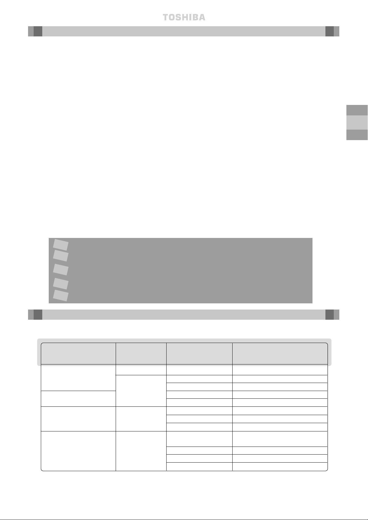
ACCESSORY MODEL TYPE ACCESSORY N
O
BASE MODEL N
O
2-WAY CASSETTE RBC-U134PG(W)-E MM-TU028/TU042/TU056
CEILING PANEL RBC-U264PG(W)-E MM-U056/U080
4-W
AY CASSETTE RBC-U464PG(W)-E MM-U112/U140
INFRA RED CEILING PANEL
RBC-U264PGR(W)-E MM-U056/U080
RBC-U464PGR(W)-E MM-U112/U140
RBC-RK162BE-PE MM-B056
FILTER KIT BUILT IN DUCT RBC-RK262BE-PE MM-B080
RBC-RK462BE-PE MM-B112/B140
43A01006 MM-C042/CR042
PAINTED BACK PANEL KIT MM-C056/CR056
(10 pack) CEILING 43A01007 MM-C080/CR080
43A01008 MM-C112/CR112
43A01009 MM-C140/CR140
CONTENTS
OPTIONAL ACCESSORIES
Passer à la page 34 pour lire le manuel d’installation en français.
Die deutsche Montageanleitung finden Sie auf Seite 66.
Por favor, vaya a la página 98 para seguir las instrucciones del manual de
instalacíon en lengua española.
Il manuale d’installazione italiano è a pagina 130.
Zie bladzijde 162 voor de Nederlandse Installatichandleiding.
F
D
E
I
NL
~ 4 ~
GB
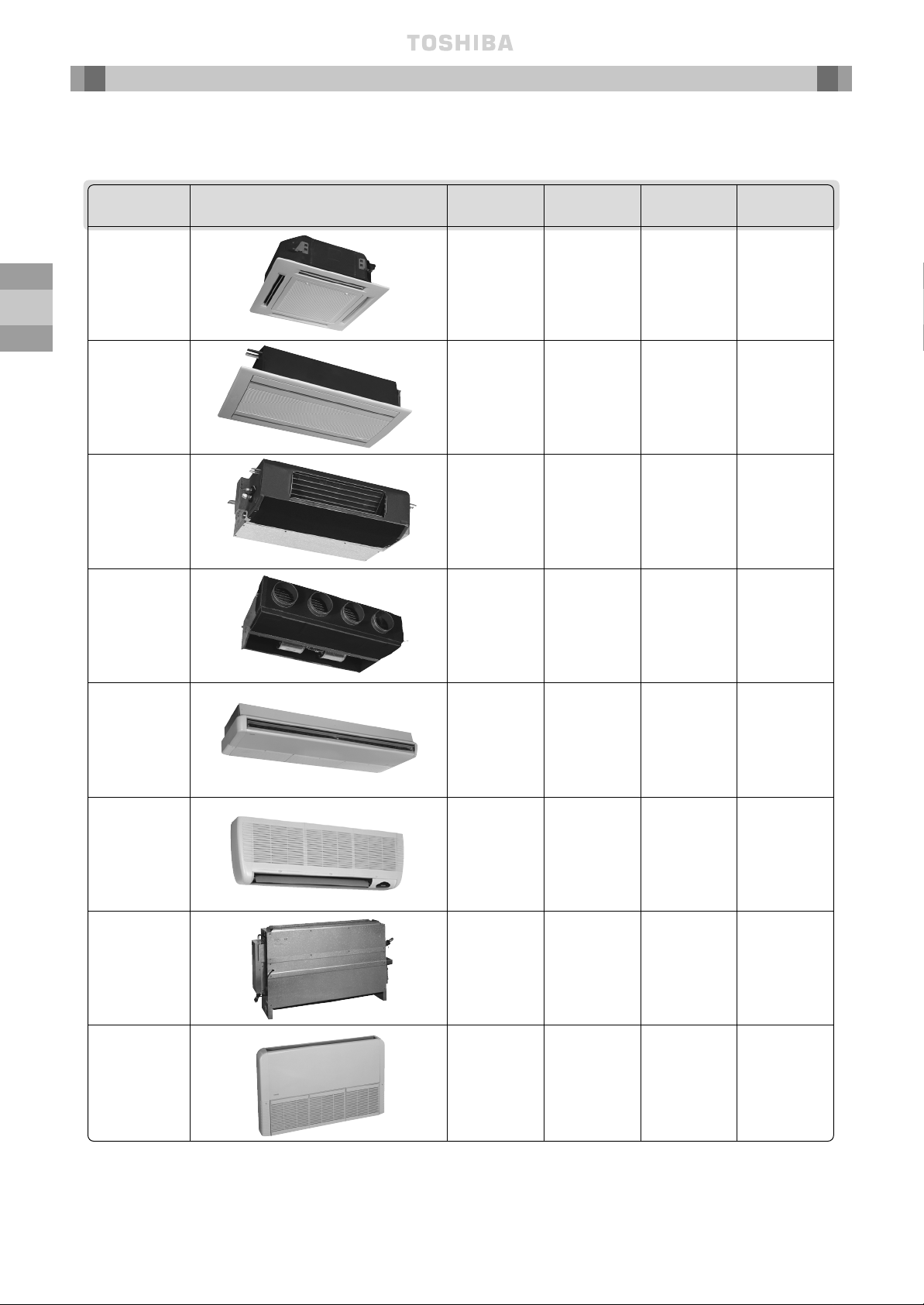
Throughout this booklet, various types of indoor units will be referred to by model codes.
Details are shown in the table below:
KEY TO
MODEL NAMES
TYPE APPEARANCE MODEL NAME CAPACITY CODE/COOLING CAPACITY HEATING CAPACITY
HP (KW) (KW)
MM-U056 2 5.6 6.4
MM-U080 3 8.0 9.6
MM-U112 4 11.2 12.8
MM-U140 5 14.0 15.8
MM-TU028 1 2.8 3.2
MM-TU042 1.5 4.2 4.8
MM-TU056 2 5.6 6.4
MM-SB028 1 2.8 3.2
MM-B056 2 5.6 6.4
MM-B080 3 8.0 9.6
MM-B112 4 11.2 12.8
MM-B140 5 14.0 15.8
MM-C/CR042 1.5 4.2 4.8
MM-C/CR056 2 5.6 6.4
MM-C/CR080 3 8.0 9.6
MM-C/CR112 4 11.2 12.8
MM-C/CR140 5 14.0 15.8
MM-K/KR042 1.5 4.2 4.8
MM-K/KR056 2 5.6 6.4
MM-K/KR080 3 8.0 9.6
MM-N028 1 2.8 3.2
MM-N042 1.5 4.2 4.8
MM-N056 2 5.6 6.4
MM-N080 3 8.0 9.6
MM-S/SR056 2 5.6 6.4
MM-S/SR080 3 8.0 9.6
4 Way Cassette
Type ‘U’
2 Way Cassette
Type ‘TU’
Built-In Slim
Duct Type ‘SB’
Built-In Duct,
Type ‘B’
Ceiling
Type ‘C’
High Wall
Type ‘K’
Carcase
Type ‘N’
Low Wall
Type ‘S’
~ 5 ~
GB
~ 5 ~
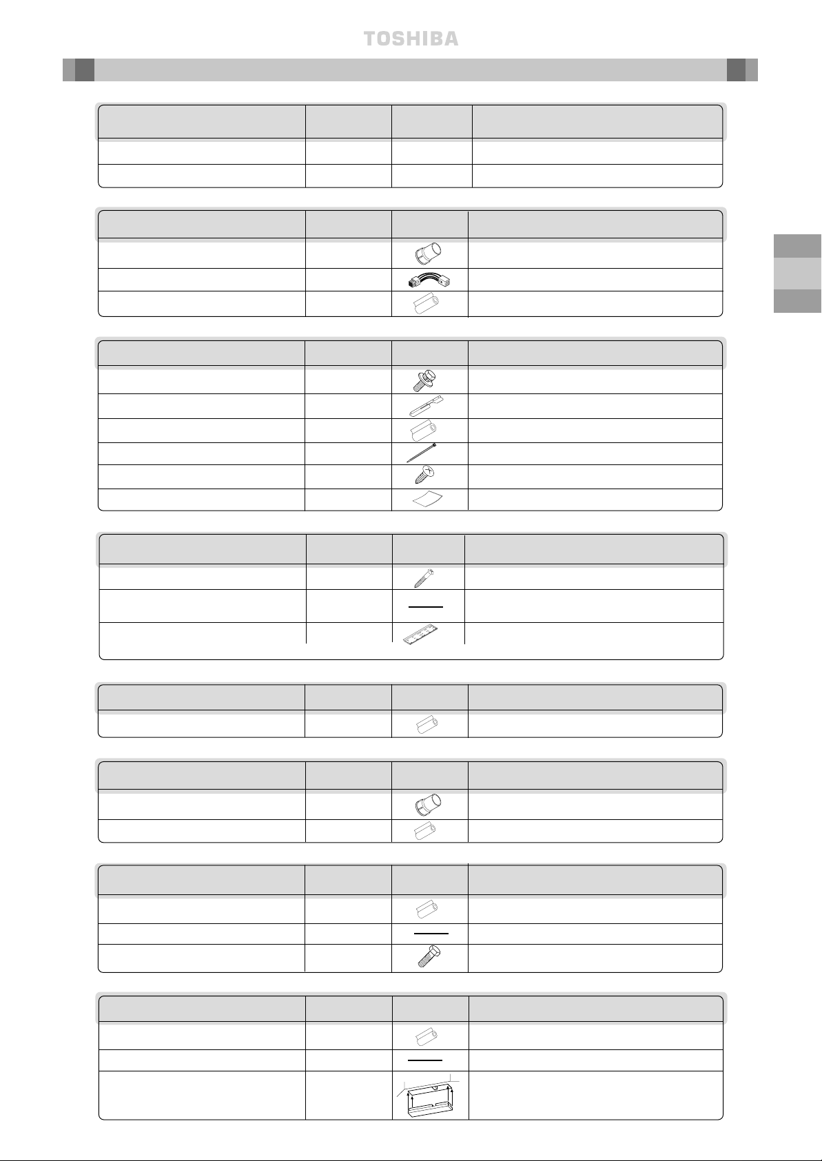
DESCRIPTION QUANTITY DIAGRAM APPLICATION
Owner’s Manual 1 — For use by customers
Installation instructions 1 This book —
COMMON
MM-B Units
MM-TU Units
DESCRIPTION QUANTITY DIAGRAM APPLICATION
PVC Socket 1 For drainpipe connection
Connector assembly 1 For fan motor tap changing
Pipe insulation 2 For insulating the pipe connections
DESCRIPTION QUANTITY DIAGRAM APPLICATION
Screws – 5.1mm dia x 45mm long
8 For fixing the installation bracket
Template for installation of 1 For ease of marking the
indoor unit location of installation bracket
Installation bracket* 1 For mounting the indoor unit on the wall
*This part is temporarily attached to the back of the indoor unit
MM-N Units
DESCRIPTION QUANTITY DIAGRAM APPLICATION
Pipe insulation 2 For insulating the pipe connections
DESCRIPTION QUANTITY DIAGRAM APPLICATION
Pipe insulation 2 For insulating the pipe connections
Cardboard template 1
For installation of the cassette and ceiling panel
Bolt (M5 x 20mm) 4 To secure the panel to the cassette
MM-U Units
D
ESCRIPTION QUANTITY DIAGRAM APPLICATION
Pipe insulation 2 For insulating the pipe connections
Cardboard template 1
For installation of the cassette and ceiling panel
Insulation block
4 (056/080)
For 2-directional and
2 (112/140)
3-directional air outlet
MM-C Units
MM-K Units
DESCRIPTION QUANTITY DIAGRAM APPLICATION
Hexagon bolt 4 For securing the hangers
Drain piping fixing plate 1 For fixing rear side drain piping
Pipe insulation 2 For insulating the pipe connections
Nylon band 10
For fixing drain piping and pipe insulation
Tapping Screw 2
For fixing the side panels after installing the unit
Insulator 1 For insulating the knock-out position
MM-SB Units
DESCRIPTION QUANTITY DIAGRAM APPLICATION
PVC Socket 1 For drainpipe connection
Pipe insulation 2 For insulating the pipe connections
ACCESSORIES
~ 6 ~
GB
Avoid installing the indoor unit in the following locations:
Where there is danger of flammable gas leakages.
Where there are high concentrations of oil.
Where the atmosphere contains an excess of salt (as in coastal areas).
The air conditioner is prone to failure when used under this condition unless special maintenance
is provided.
Where high concentrations of organic solvent are present.
Where a machine that generates high frequencies is operated.
Where the unit will not be horizontal.
Where the ceiling height is more than 3m.
Where the floor/wall/ceiling structure is unable to support the weight of the unit.
Where it is not possible to fix the unit hangers, e.g. window glass.
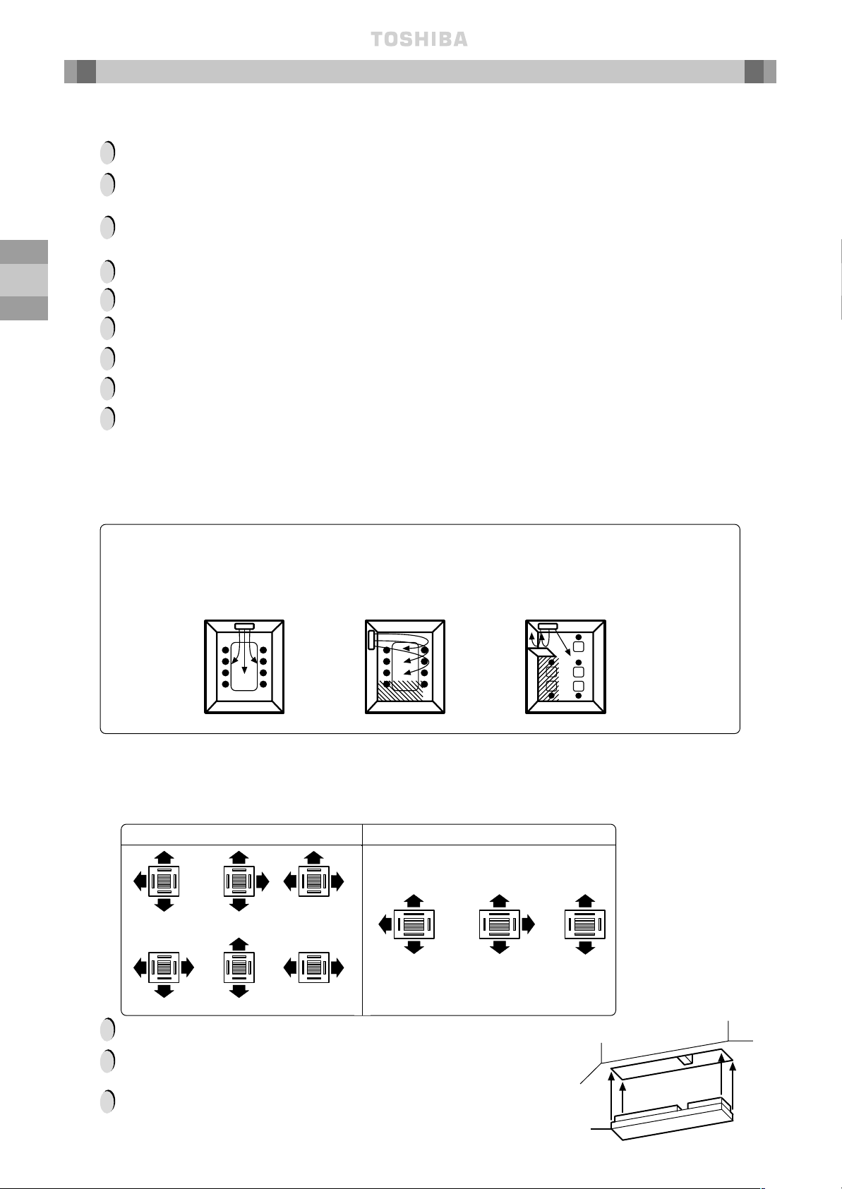
Locate the unit so as to provide uniform circulation of chilled air.
Location Precautions
Good location —
Evenly cooled
Bad location —
Oblique-line
area not well
cooled \\\\\
Bad location —
Oblique-line
area not well
cooled /////
✗
✗
If a good location is not possible, use a fan to circulate the air evenly throughout the room.
— MM-U Units only —
Choose the number of airflows that are required, depending on the shape of the room and the
location of the indoor unit.
Insulation
Block
MM-U056/U080 MM-U112/U140
!
!
!
!
!
!
!
!
!
!
!
!
— MM-C and MM-K Units only —
Avoid locating the unit as shown in the ✗-marked figures below:
It is not possible to block the air flow from the longer sides of the unit (U112/U140).
The number of airflow directions cannot be adjusted after installation.
Insert insulation blocks, which are supplied as accessories,
at each side where the airflow is not required,
as shown in the diagram opposite.
3-way 3-way 3-way
3-way 3-way 2-way
3-way 2-way 2-way
INDOOR
UNIT LOCATION
~ 7 ~
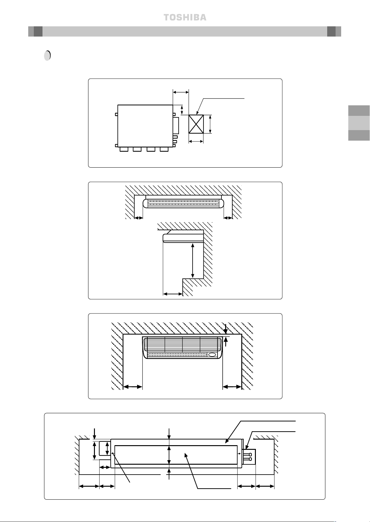
GB
ALWAYS ENSURE THAT THERE IS SUFFICIENT SPACE AROUND THE INDOOR UNITS FOR
INSTALLATION AND SERVICING:
Service and Installation Space
MM-B Units
MM-C, CR Units
MM-K, KR Units
300mm or more
30mm or more
300mm or more
500mm or
more
400mm
or
more
150mm
or more
300 – 400mm
200mm
450mm
450mm
!
Provide an inspection
hole in this position
Inspection hole
150mm
or more
MM-N Units
Minimum
Upper Plate/Duct Plate
Minimum
60mm
25mm
20mm
148mm
65mm
90mm
150mm
100mm
Drain Catch
Fixing location to
floor/base
160mm
145mm
Air Outlet
150mm
INDOOR
UNIT LOCATION
~ 8 ~
GB
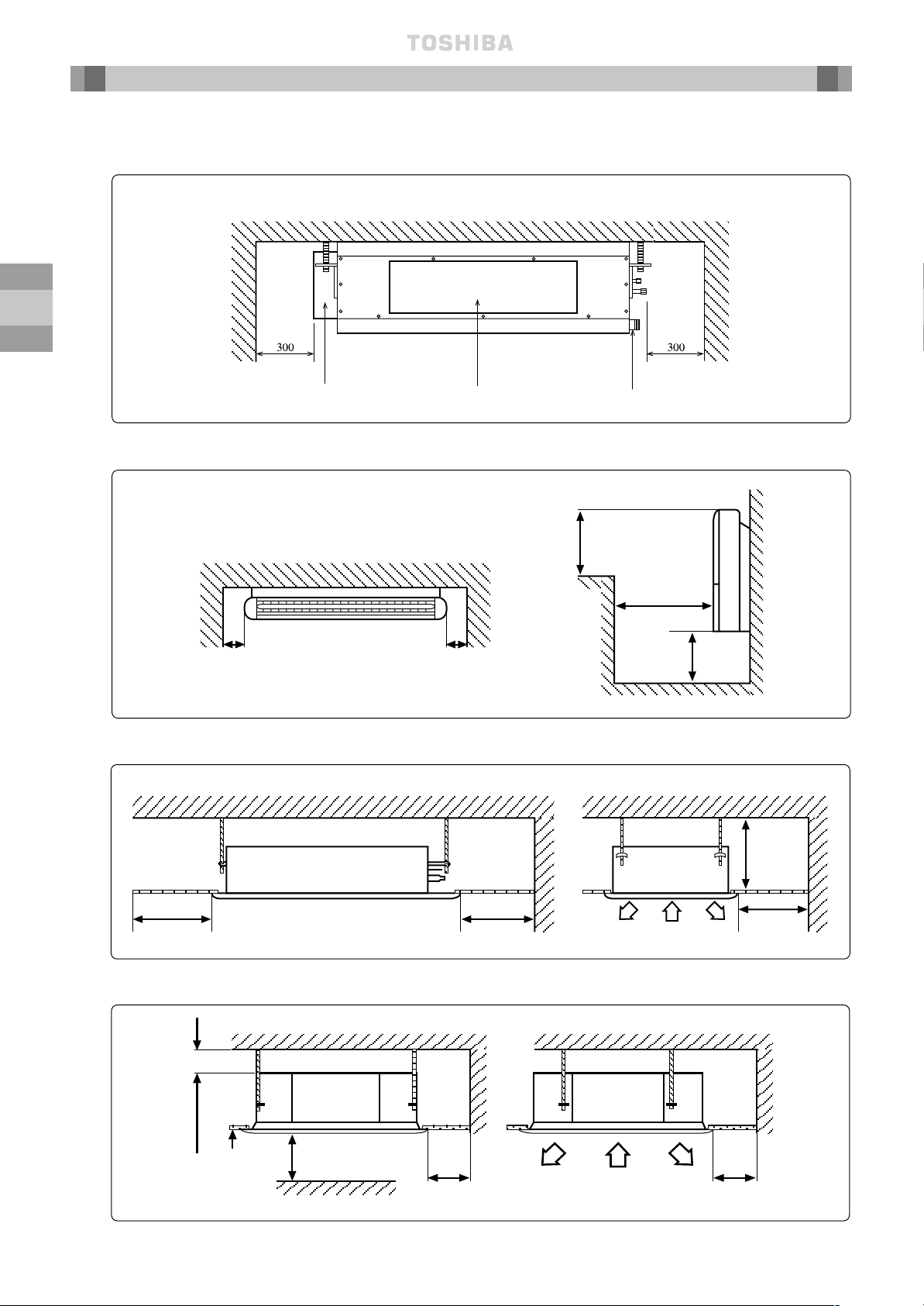
Service and Installation Space continued
MM-SB Units
MM-S, SR Units
MM-TU Units
MM-U Units
Plan View
150mm
or more
150mm
or more
400mm
or more
500mm
or more
150mm
or more
15mm or more
1000mm
or more
Obstacle
1000mm
or more
Ceiling
1000mm or more
Drain pipe connections
Air Outlet
Electrical box
INDOOR
UNIT LOCATION
600mm 600mm
600mm
200mm
~ 9 ~
GB
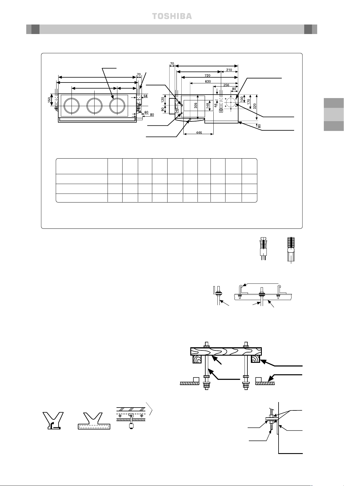
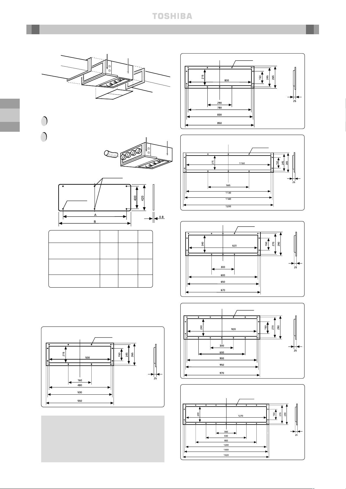
Check the dimensions of the unit illustrated in the following figure:
Unit Installation – MM-B Units
Installing Ø 10 Hanging Bolts (4 pieces)
Install the hanging bolts at the intervals shown in the
following figure.
Use Ø 10 hanging bolts (to be locally procured).
Ceiling preparation: The actual procedure differs according
to the structure. Consult your builder or whoever was
responsible for the interior of the house/building.
Removal of part of the ceiling plate:
(1) In order to ensure that the ceiling is kept perfectly
horizontal and to prevent the ceiling from vibrating, the
ceiling framework must be reinforced.
(2) Cut and remove part of the ceiling framework.
(3) Reinforce the ends of the ceiling framework where it was
cut and add framework to secure the ends.
Some piping and wiring connections must be made in the
ceiling after the unit has been suspended. After selecting where
the unit will be installed, decide on the direction of the piping
connection. If the ceiling is already installed, prepare the
refrigerant pipes, drain pipe, indoor to outdoor unit connection
wiring and the remote control cord at the piping and wiring
connection positions before suspending the indoor unit.
Hanger
bolt
Hanging bolt
Hanging
bolt
Beam
Ceiling
Model (MM-) A B E Ø F Ø G H J K M N
B056 700 750 780 12.7 6.4 252 280 280 1 2
B080 1000 1050 1080 15.9 9.5 252 580 290 2 3
B112, B140 1350 1400 1430 19.0 9.5 252 930 310 3 4
Sliding bracket
Reinforcing
bar
Foundation bolt
(Foundation bolt for
hanging the piping)
Angular bracket
for support
Installation on a wooden structure:
Place a length of wood of the appropriate size across two
beams and install the hanging bolts onto this length of wood.
Installation on a steel frame:
Use the angular
bracket in
the structure
or install
one for support.
Installation on an existing
concrete slab:
Use hole-in anchors, hole-in plugs
or hole-in bolts for the installation.
Hanging Unit
(1) Raise the unit by using a
lifting device, then secure
the hangers to the hanging
bolts. Be sure to fix the nuts
onto both the upper and
under side of the hanger
and the washer (under side
only);
(2) Install the unit horizontally
by using a level. Failure to
do this will cause water
leakages.
Nut
Hanger
Hanging
Bolt
Washer
How to Install the Hanging Bolts
Installation on a newly installed concrete slab:
Use insert brackets or foundation bolts for the installation.
Cross
length of
wood
Knife shaped
bracket
(Gas ø F)
Hanging Bolt Pitch B
Refrigerant Pipe
Connection
Unit Dimension A
Hanging Bolt
4-M10
Provided at site
Nx Ø200
Air Outlet
Drain pipe connection
(inner diameter 32)
(diameter 32 minimal for PVC pipes)
Refrigerant pipe
connection
(liquid ø G)
Hanging Bolt Pitch:565
Unit Dimension:800
J = M x K
(H)
6 x Ø4 holes (Ø160)
Fresh air inlet Ø125
cut-out (other side)
Filter kit
INDOOR
UNIT LOCATION
~ 10 ~
GB
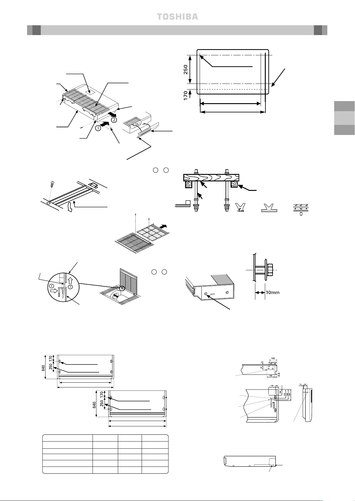
Unit Installation – MM-B Units continued
Connection of Ducting
Remove the duct connection assembly (attachment)
before connecting the supply duct.
!
Flexible duct
The maximum length of
flexible ducting is 10m.
To connect the shelter
board under the lower air
inlet of unit, prepare the
shelter board locally, as
shown below.
!
Model (MM-) A B C
B056 400 700 —
B080 700 1000 2
B112, B140 1050 1350 2
Optional Accessory
A TOSHIBA Long-Life Filter Kit is available as an
optional accessory.
The Filter Kit can be installed on either the lower or
rear air inlet of the Duct Type unit.
To connect square duct, prepare the connection flange
locally as shown below:
MM-B056
Supply Flanges
Supply Flanges Continued
MM-B080
MM-B112, MM-B140
Return Flanges
MM-B056
MM-B080
MM-B112, MM-B140
Shelter Board C x Ø6 holes
Supply duct
(local procurement)
12 – ø 6 holes
14 – ø 6 holes
14 – ø 6 holes
14 – ø 6 holes
18 – ø 6 holes
22 – ø 6 holes
4 x Ø6 holes
Return duct (local
procurement)
Shelter board
(local procurement)
INDOOR
UNIT LOCATION
~ 11 ~
GB
Unit Installation – MM-C, MM-CR Units
Before Installation
1 Take off the accessories.
2 Remove
the hanger
(left, right).
4 Remove the side panels by hand.
Slide them in order of 1 - 2 .
5 Pull the air filter
out then remove
the inlet grille fixing
screws.
Side
panel
(left)
Body
Inlet grille
10-20mm
Securely fix left
and right side
panels with a screw
supplied after unit
installation.
Installing Ø 10 Hanging Bolts
Ø Hanging Bolts are procured locally
Install hanging bolts at the spacings shown below.
Shipping fixture
(centre)
Detail figure of the hinge
portion
INNER HANGING
OUTER HANGING
Hole for hanging bolt
Bmm (Hanging bolt pitch)
Amm
Model (MM-) Amm Bmm Cmm
MM-C/CR042 1030 920 1020
MM-C/CR056 1030 920 1020
MM-C/CR080 1230 1120 1220
MM-C/CR112 1430 1320 1420
MM-C/CR140 1630 1520 1620
The positions of the hanging bolts are printed on the
carton box. (The size is not printed.)
Position of hanging bolt
(ø10 printed)
Bmm (inner hanging)
Cmm (outer hanging)
Installing method of the Hanging Bolt
Newly-built concrete slab
Install hanging bolts with
inserts, embedded bolts, etc.
Wooden-strutted room
Install hanging bolts on a square
wooden piece placed over beams.
Edge
(sharp
insert)
(Slide
insert)
Embedded bolt
of piping
Reinforcing bar
Installing Hexagon Bolt (accessory)
Allow a spacing of
about 10mm
M8 x 25mm hexagon bolts (4)
Determining installation position and direction
of the piping and wiring
BACK VIEW
Knock out
(rear attachment)
Gas line connection
Knock out
(right or left attach-
ment)
Liquid line connection
TOP VIEW
Opening Knock Out Hole
Cut the slit
portion by a
saw or knife
In case of
right or left
attachment
Slit
3 Remove all the
metal shipping
fixtures (left
corner, centre,
right corner).
Side panel
(right)
Wooden
piece
Hanging
bolt
Drain connection
(OD 20mm)
Beam
Hole for hanging bolt
Cmm (Hanging bolt pitch)
Amm
(4 – 12 x 27 slots)
Hanging bolt pitch
(4 – 12 x 27 slots)
Hanging bolt pitch
The dotted
line indicates
the rear end
of the unit. To
be detached
on the dotted
line.
Embedded
bolt
SIDE VIEW
To remove the
inlet grille take the
hinge portion off in
order of 1 - 2 .
Hinge
Body
INDOOR
UNIT LOCATION
 Loading...