

Toshiba MMC-AP0181H2UL, MMC-AP0241H2UL, MMC-AP0361H2UL, MMC-AP0421H2UL Installation Manual
Installation manual 1
English
Manuel d’installation 17
Français
AIR CONDITIONER (MULTI TYPE)
Indoor Unit
Model name:
Ceiling type
MMC-AP0181H2UL
MMC-AP0241H2UL
MMC-AP0361H2UL
MMC-AP0421H2UL
Installation manual
+00EH99876401_00Ta.book Page 1 Monday, January 17 , 2011 10:47 AM
–1–
Ceiling type
Installation Manual
Ceiling type
Installation Manual
Contents
1 Accessory Parts . . . . . . . . . . . . . . . . . . . . . . . . . . . . . . . . . . . . . . . . . . . . . . . . . . . . . . 1
2 Precautions for Safety . . . . . . . . . . . . . . . . . . . . . . . . . . . . . . . . . . . . . . . . . . . . . . . . . 2
3 Selection of Installation Place . . . . . . . . . . . . . . . . . . . . . . . . . . . . . . . . . . . . . . . . . . . 3
4 Installation . . . . . . . . . . . . . . . . . . . . . . . . . . . . . . . . . . . . . . . . . . . . . . . . . . . . . . . . . . . 4
5 Refrigerant Piping . . . . . . . . . . . . . . . . . . . . . . . . . . . . . . . . . . . . . . . . . . . . . . . . . . . . . 6
6 Drain Piping Work . . . . . . . . . . . . . . . . . . . . . . . . . . . . . . . . . . . . . . . . . . . . . . . . . . . . . 7
7 Electrical Connection . . . . . . . . . . . . . . . . . . . . . . . . . . . . . . . . . . . . . . . . . . . . . . . . . . 8
8 Applicable Controls . . . . . . . . . . . . . . . . . . . . . . . . . . . . . . . . . . . . . . . . . . . . . . . . . . 11
9 Test Run. . . . . . . . . . . . . . . . . . . . . . . . . . . . . . . . . . . . . . . . . . . . . . . . . . . . . . . . . . . . 12
10 Troubleshooting . . . . . . . . . . . . . . . . . . . . . . . . . . . . . . . . . . . . . . . . . . . . . . . . . . . . . 13
Please read this manual thoroughly before installation work and install the products correctly.
• This Manual describes the installation method of the indoor unit.
• For installation of the outdoor unit, refer to the Installation Manual of the outdoor unit.
ADOPTION OF NEW REFRIGERANT
This Air Conditioner uses R410A an environmentally friendly refrigerant.
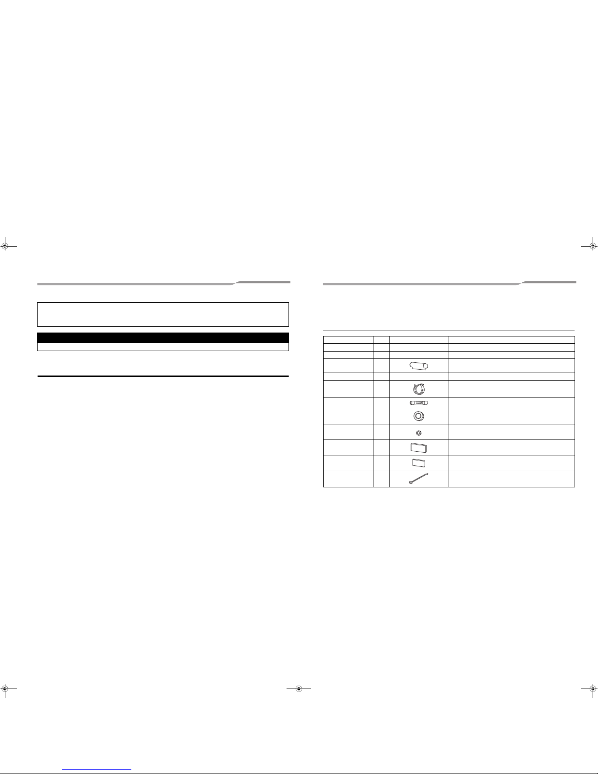
1 Accessory Parts
Accessory parts
Part name Q’ty Shape Usage
Installation Manual 1 This manual –
Installation pattern 1 – Drawing-out port of hanging bolt pipe
Heat insulation pipe 2 For heat insulation of pipe connecting section
Washer 4 3/8” (M10) × Ø1.0” (25 mm) For holding down unit
Hose band 2 For connecting drain pipe
Drain hose 1 For connecting drain pipe
Bushing Ø2.2” (Ø56) 1 For protection of edge at hole for remote control wires
Bushing Ø1.1” (Ø28) 1 For sealing the back side conduit hole
Heat insulator 1
For heat insulation of drain hose
(0.4” - thickness × 7.5” × 7.5” (10 - thickness × 190 × 190 mm))
Heat insulator of top
plate
1
For upper pipe hole of indoor unit
(0.2” - thickness × 5.1” × 6.3” (6 - thickness × 130 × 160 mm))
Banding band 2 For prevention of open of drain hose heat insulator
1-EN 2-EN
+00EH99876401_00Ta.book Page 1 Monday, January 17 , 2011 10:47 AM
–2–
Ceiling type
Installation Manual
EN
Ceiling type
Installation Manual
2 Precautions for Safety
Installing, starting up, and servicing air--conditioning equipment can be hazardous due to system pressures,
electrical components, and equipment location (roofs, elevated structures, etc.).
Only trained, qualified installers and service mechanics should install, start--up, and service this equipment.
Untrained personnel can perform basic maintenance functions such as cleaning heat exchanger. All other
operations should be performed by trained service personnel.
Before working on the equipment, observe precautions in the literature and on tags, stickers, and labels attached
to the equipment.
Follow all safety codes.Wear safety glasses and work gloves. Keep quenching cloth and fire extinguisher nearby
during brazing. Use care in handling, rigging, and setting bulky equipment.
Read these instructions thoroughly and follow all warnings or cautions included in literature and attached to the
unit. Consult local building codes and National Electrical Code (NEC) for special requirements. Recognize safety
information. This is the safety--alert symbol . When you see this symbol on the unit and in instructions or
manuals, be alert to the potential for personal injury.Understand these signal words: DANGER, WARNING, and
CAUTION. These words are used with the safety--alert symbol.
DANGER identifies the most serious hazards which will result in severe personal injury or death. WARNING
signifies hazards which could result in personal injury or death. CAUTION is used to identify unsafe practices which
may result in minor personal injury or product and property damage. NOTE is used to highlight suggestions which
will result in enhanced installation, reliability, or operation.
The manufacturer shall not assume any liability for the damage caused by not observing the description of this
manual.
WARNING
• Only a qualified installer or service pers on is allowed to do installation work.
Inappropriate installation may result in water leakage, electr ic shock or fire.
• Do not use any refrigerant different from the one specified for complement or replacement.
Otherwise, abnormally high pressure may be generated in the refrigeration cycle, which may result in a
failure or explosion of the product or an injury to your body.
• Connect ground wire. (grounding work)
Incomplete grounding may cause an electric shock.
Do not connect ground wires to gas pipes, water pipes, lig htning rods or ground wires for telephone wires.
• Turn off all the circuit breaker before attempting any electrical work.
Failure to do so may cause electric shock.
• Install the refrigerant pipe securely during the installation work before operating the air conditioner.
If the air conditioner is operated with the valve open and without the refrigerant pipe, the compressor sucks air and
the refrigeration cycle is overpressurized, which may cause a burst or injury.
• When moving the air conditioner for the installation into another place, do not enter any gaseous matter
other than the specified refrigerant into the refrigeration cycle.
If air or any other gas is mixed in the refrigerant, the gas pressure in the refrigeration cycle becom es abnormally high
and it resultingly causes pipe burst and injuries on persons.
• Perform installation work properly according to the Inst allation Manual.
Inappropriate installation may result in water leakage, electr ic shock or fire.
• When the air conditioner is installed in a small room, provide appropriate measures to ensure that the
concentration of refrigerant leakage occur in the room does not exceed the critical level.
• Install the air conditioner securely in a location where the base can sustain the weight adequately.
• Perform the specified installation work to guard against an earthquake.
If the air conditioner is not installed appropriately, accide nts may occur due to the falling unit.
• If refrigerant gas has leaked during the installation work, ventilate the room immediat ely.
If the leaked refrigerant gas comes in contact with fire, no xious gas may generate.
• After the installation work, confirm that refrigerant gas does not leak.
If refrigerant gas leaks into the room and flows near a f ire source, such as a cooking range, noxious gas might
generate.
• Electrical work must be performed by a quali fied electrician in accordance with the Installation Manual. Use
an exclusive power supply for the air conditioner at the ra ted voltage.
An insufficient power supply capacity or inappropriate installation may cause fire.
• Use the specified wires for wiring conn ect the terminals. Securely fix them to prevent external forces applied
to the terminals from affecting the terminals.
• Conform to the regulations of the local electric company when wiring the power supply.
• For the refrigerant recovery work (collection of refrigerant from the pipe to the compressor), stop the
compressor before disconnecting the refrigerant pipe.
If the refrigerant pipe is disconnected while the compressor is working with the valve open, the compressor sucks air
and the refrigeration cycle is overpressurized, which may cause a burst or injury.
CAUTION
• THIS AIR CONDITIONER ADOPTS THE NEW HFC REFRIGERANT (R410A) WHICH DOES NOT DESTROY
OZONE LAYER.
• The characteristics of R410A refrigerant are; easy to absorb water, oxidizing membrane or oil, and its pressure is
approx. 1.6 times higher than that of refriger ant R22. Accompanied with the new refrigerant, refrigerating oil has also
been changed. Therefore, during installation work, be sure that water, dust, former refrigerant, or refrigerating oil does
not enter the refrigerating cycle.
• To prevent charging an incorrect refrigerant and refriger ating oil, the sizes of connecting sections of charging port of
the main unit and installation tools are changed from tho se for the conventional refrigerant.
• Accordingly the exclusive tools are required for the new refrigerant (R410A).
• For connecting pipes, use new and clean piping designed for R410A, and please care so that wate r or dust does not
enter.
• Tighten the flare nut with a torq ue wrench in the specified manner.
Excessive tightening of the flare nut may cause a crack in the flare nut after a long period, which may result in
refrigerant leakage.
• Wear heavy gloves during the in stallation work to avoid injury.
3-EN 4-EN
+00EH99876401_00Ta.book Page 2 Monday, January 17 , 2011 10:47 AM
Ceiling type
Installation Manual
Ceiling type
Installation Manual
–3–
3 Selection of Installation Place
WARNING
• Install the air conditioner securely in a location where the base can sustain the weight adequately.
If the strength is not enough, the unit may fall down resulting in injury.
• Install the air conditioner at a heig ht 8’ (2.4 m) or more from the floor.
If you insert your hands or others directly into the unit while the air conditioner operates, it is dangerous because you
may contact with revolving fan or active electricity.
CAUTION
• Do not install in a location where flammable gas may leaks are possible.
If the gas leak and accumulate around the unit, it may ignite and cause a fire.
Upon approval of the customer, install the air conditioner in a place that satisfies the following
conditions.
• Place where the unit can be installed horizontally.
• Place where a sufficient servicing space can be ensured for safety maintenance and check.
• Place where drained water will not cause any problem.
Avoid installing in the following places.
• Place exposed to air with high salt content (seaside area), or place exposed to large quantities of sulfide gas (hot
spring).
(Should the unit be used in these places, special protective measures are needed.)
• A restaurant kitchen where a lot of oil is used or place near machines in a factory (Oil adhering to the heat
exchanger and resin part (turbo fan) in the indoor unit may reduce the performance, generate mist or dew drop,
or deform or damage resin parts.)
• Place where organic solvent is used nearby.
• Place close to a machine generating high frequency.
• Place where the discharged air blows directly into the window of the neighbor house. (Outdoor unit)
• Place where noise of the outdoor unit is easily transmitted.
(When the outdoor unit is installed on the boundary with the neighbor, pay due attention to the level of noise.)
• Place with poor ventilation. (Before air duct work, check whether value of fan speed, static pressure and duct
resistance are correct.)
• Do not use the air conditioner for special purposes such as preserving food, precision instruments, or art objects,
or where breeding animals or growing plants are kept. (This may degrade the quality of preserved materials.)
• Place where any of high-frequency appliances (including inverter devices, private power generators, medical
equipment, and communication equipment) and inverter-type fluorescent light is installed.
(A malfunction of the air conditioner, abnormal control, or problems due to noise to such appliances/equipment
may occur.)
• When the wireless remote control is used in a room equipped with an inverter-type fluorescent light or at a place
exposed to direct sunlight, signals from the remote control may not be received correctly.
• Place where organic solvent is used.
• Place near a door or window exposed to humid outside air (Dew drop may form.).
• Place where special spray is used frequently.
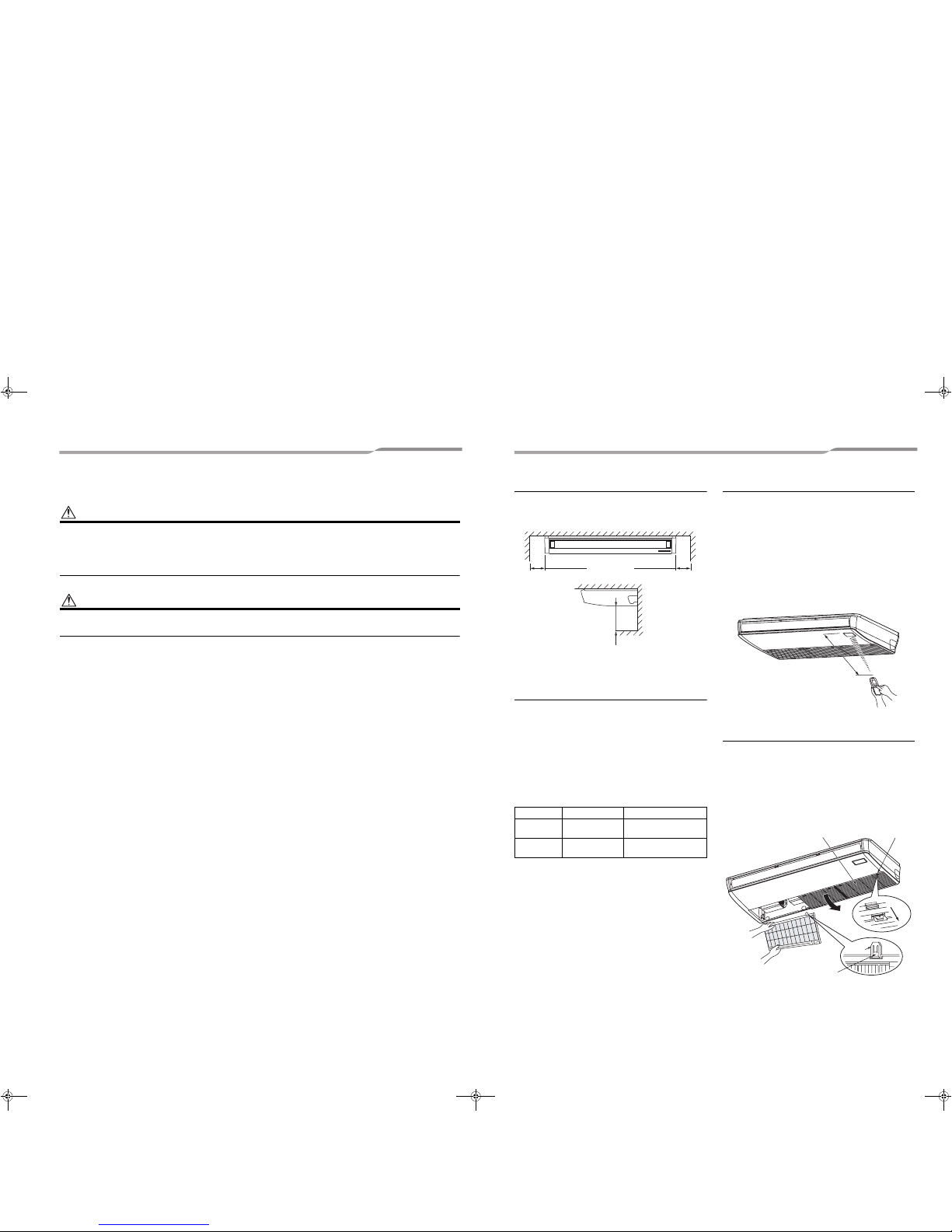
Installation space
Secure the specified space in the figure for
installation and servicing.
unit: in (mm)
Ceiling height
Set the installable height of the ceiling within 13’1” (4
m), otherwise the air distribution will become poor.
If height of ceiling exceeds 11’6” (3.5 m), hot air
becomes difficult to reach the floor surface, and then
the change of setup of high ceiling is necessary.
For the change method of high ceiling, refer to the
application control, “Installing indoor unit on high
ceiling” in this Manual.
List of installable ceiling height
According to the conditions of installation, setup time of
turning-on of filter sign (notification of filter cleaning) of
the remote control can be changed.
When it is difficult to warm up the room due to
installation place or structure of the room, the detection
temperature of heating can be raised.
For change the setup time, refer to the application
control, “Filter sign setting” and “To secure better effect
of heating” in this Manual.
Wireless remote control
Decide the position which remote control is operated
and the installation place.
And then refer to the Installation Manual of the wireless
remote controller kit sold separately.
(The signal of the wireless type remote control can be
received within approx. 23’ (7 m). This distance is a
criterion and varies a little according to capacity of the
battery, etc.)
• To prevent malfunction, select a place where is not
affected by a fluorescent lamp or direct sunlight.
• Two or more (up to 6 units) wireless-type indoor units
can be set in a room.
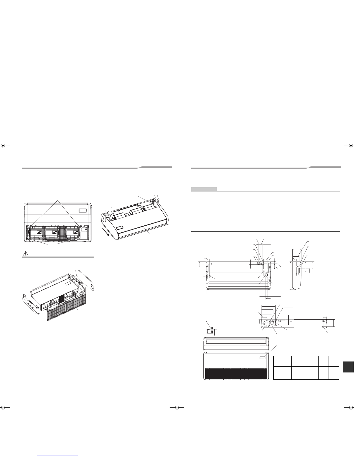
Before installation
1 Removal of suction grille
Slide the suction grille fixing knobs (2 positions)
toward the arrow direction, and then open the
suction grille.
Under the condition of suction grille opened, push
the hook section of hinges (2 positions) at the rear
side, and then pull out the suction grille.
Setup data
0000
Standard
(Factory default)
11’6” (3.5 m) or less
0001 High ceiling 1
more than 11’6” (3.5 m)
up to 13’1” (4.0 m)
9.8” (250)
or more
19.7” (500) or more
9.8” (250)
or more
A
p
p
r
o
x
.
2
3
’
(
7
m
)
Pull out suction grille
while pushing hook.
Suction grille
fixing knob
Suction grille
Hinge
S
l
i
d
e
5-EN 6-EN
+00EH99876401_00Ta.book Page 3 Monday, January 17 , 2011 10:47 AM
Ceiling type
Installation Manual
EN
Ceiling type
Installation Manual
–4–
2 Removing wire guard
Remove the screws (2 pcs.) which are fixing the
wire guard.
Remove the clamp fixing screws and remove the
wire guard.
CAUTION
Attach back the wire guard once indoor unit is installed.
Remove the 2 screws fixing the wire guard and hung the
wire guard with the clamps during a service.
3 Removal of side panel
After removing the side panel fixing screws (1
each at right and left), slide the side panel forward
and then remove it.
4 Removal of protective vinyl
Peel out the protective vinyl on the level louver.
5 Removal of protector
Remove the protector (1 pcs.) of the fan.
(AP024 only)
Clamps
Screw
Wire guard
Protector
Slide forward.
Level louver
Side panel
4 Installation
REQUIREMENT
Strictly comply with the following rules to prevent damage of the indoor units and human injury.
• Do not put a heavy article on the indoor unit. (Even units are packaged)
• Carry in the indoor unit as it is packaged if possible. If carrying in the indo or unit unpacked by necessity, use buffering
cloth or other soft cloth to not damage the unit.
• To move the indoor unit, hold the hooking metals (4 positions) only.
Do not apply force to the other parts (refrigerant pip e, drain pan, foamed parts, or resin parts).
• Carry the package by two or more persons, an d do not bundle it with plastic band at positions other than specified.
External view
Unit: in (mm)
A
Unit: in (mm)
Model MMC- A B C D
AP018
35.8”
(910)
33.7”
(855)
Ø1/4”
(6.4)
Ø1/2”
(12.7)
AP024
46.5”
(1180)
44.3”
(1125)
Ø3/8”
(9.5)
Ø5/8”
(15.9)
AP036, AP042
62.8”
(1595)
60.6”
(1540)
Conduit hole
(Hole for power supply cable. knoc kout)
Hole for remote control wires (knockout)
Left drain size
Refrigerant pipe
(Liquid side ØC)
B (Hanging position)
Refrigerant pipe (Gas side ØD)
Upper pipe draw-out port (knockout)
Pipe draw-out port
(knockout)
Drain port VP20
(Inner dia. Ø1.0” (26), hose
attached)
8.5” (216) (Gas pipe)
7.9” (200) (Liquid pipe)
Drain pipe
connecting
port
Hole for remote control wires
Conduit hole
(knockout)
Left drain pipe
draw-out port
(knockout)
Hole for power supply cable
Outside air take-in port (Duct sold separately)
Knockout hole Ø3.6” (92))
Pipe hole on wall
(Ø3.9” (100) hole)
Unit
Ceiling surface
Hanging bolt
Within
2.0” (50)
Wireless sensor mounting section
3.3” (84)
8.5” (216)
4.3” (110)
3.0” (76)
4.1” (105)
8.3” (210)
6.6” (167)
3.8” (97)
3.0” (75)
5.7” (146)
13.7” (347)
12.2” (311)
5.3” (135)
3.3” (84)
12.6” (320)
6.7” (170)
5.7” (145)
3.5”
(90)
1.3” (32)
3.6” (92)
6.7” (171)
2.1”
(53)
5.1” (130)
2.0” (50)
26.8” (680)
5.6” (141)
4.5” (114)
10.3” (262)
1.5” (39) 2.0” (52)
2.8”
(70)
7-EN 8-EN
+00EH99876401_00Ta.book Page 4 Monday, January 17 , 2011 10:47 AM
Ceiling type
Installation Manual
Ceiling type
Installation Manual
–5–
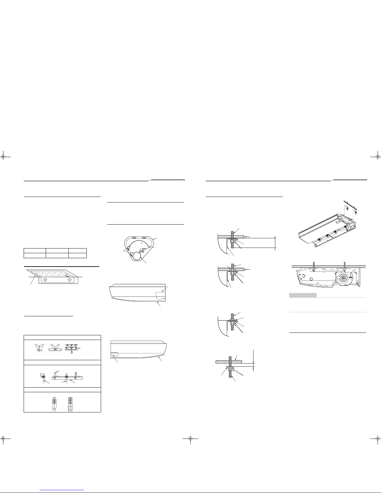
Installation of hanging bolts
• Consider the piping/wiring after the unit is hung to
determine the location of the indoor unit installation
and orientation.
• The hanging bolt pitches are given in the outline
drawing and the attached installation pattern.
• When a ceiling already exists, lay the drain pipe,
refrigerant pipe, control wires, and remote control
wires to their connection locations before hanging
the indoor unit.
Procure hanging bolts and nuts for installing the indoor
unit (these are not supplied).
Using the installation pattern (accessory)
Using the pattern, positioning of the hanging bolt and
pipe hole can be performed.
* As an error to some degree may generate on the
pattern size due to temperature and humidity, be
sure to confirm the size.
Installation of hanging bolt
Use 3/8” (M10) hanging bolts (4 pcs, to be local
procure). Matching to the existing structure, set pitch
according to size in the unit external view as shown
below.
Draw-out direction of pipe/
wire
• Decide installation place of the unit and draw-out
direction of pipe and wire.
Pipe knockout hole
• Piping from rear side
* Cut off the groove section with a plastic cutter, etc.
• Piping from right side
* Cut off the groove section with a metal saw or
plastic cutter, etc.
• Piping from left side
Taking pipe from left side is applied only to the
drain pipe.
The refrigerant pipe cannot be taken out from the
left side.
* Cut off the groove section with a metal saw or
plastic cutter, etc.
• Piping from upper side
Taking pipe from upper side is applied only to
the refrigerant pipe.
When taking out the drain pipe from the upper
side, use a drain up kit sold separately.
Open the upper pipe draw-out port (Knockout hole)
shown in the external view.
(Knockout hole of thin plate)
After piping, cut off the attached heat insulator of the
top plate to pipe shape, and then seal the knockout
hole.
Hanging bolt 3/8” (M10) 4 pieces
Nut 3/8” (M10) 12 pieces
New concrete slab
Install the bolts with insert brackets or anchor bolts.
Steel flame structure
Use existing angles or install new support angles.
Existing concrete slab
Use a hole-in anchors, hole-in plugs, or a hole-in bolts.
Ceiling surface
Installation pattern
Wall face
Rubber
Anchor bolt
(Blade type
bracket)
(Slide type
bracket)
(Pipe hanging
anchor bolt)
Hanging bolt
Hanging bolt Support angle
100
Rear cover
Opened when
refrigerant pipe is
taken out from the
rear side
Grooves
Opened when only drain pipe is taken
out from the rear side
Groove
Side panel (Right side)
Groove
Side panel
(Left side)
Installation of indoor unit
• Preparation before holding down main unit
* Confirm the presence of the ceiling material
beforehand because the fixing method of hanging
metal when the ceiling material is set differs from
that when the ceiling material is not set.
▼ There is ceiling material
* Tighten the hanging metal with upper/lower nuts
as shown in the figure.
▼ There is no ceiling material
• Holding down of main unit
(1) Attach washer and nuts to the hanging bolt.
(2) Hang the unit to the hanging bolt as shown the
figure below.
(3) As shown in the figure below, fix the ceiling material
securely with the double nuts.
REQUIREMENT
• The ceiling surface may not be horizontal. Be sure
to confirm that width and depth directions are
level.
Installation of remote control
(Sold separately)
For installation of the wired remote control, follow the
Installation Manual attached with the remote control.
• Pull out the remote control cord together with the
refrigerant pipe or drain pipe.
Pass the remote control cord through upper side of
the refrigerant pipe and drain pipe.
• Do not leave the remote control at a place exposed
to the direct sunlight and near a stove.
Ceiling surface
Double nut
(Procured locally)
Hanging bolt
(Procured locally)
Washer (Accessory)
Hanging metal
Indoor
unit
2.0” (50 mm)
Ceiling surface
Double nut
(Procured locally)
Hanging bolt
(Procured locally)
Washer (Accessory)
Hanging metal
Indoor
unit
Nut
(Procured locally)
Washer
(Procured locally)
Double nut
(Procured locally)
Hanging bolt
(Procured locally)
Washer (Accessory)
Indoor
unit
Double nut
(Procured locally)
Hanging bolt
Ceiling surface
Washer
(Accessory)
0.8” - 1.2”
(20 - 30 mm)
9-EN 10-EN
+00EH99876401_00Ta.book Page 5 Monday, January 17 , 2011 10:47 AM
 Loading...