

Toshiba MMC-AP0157HP-E-TR, MMC-AP0187HP-E-TR, MMC-AP0247HP-E-TR, MMC-AP0277HP-E-TR, MMC-AP0367HP-E-TR Service Manual
...
SERVICE MANUAL
AIR-CONDITIONER
(MULTI TYPE)
FILE NO. SVM-13085
INDOOR UNIT
<Ceiling type>
MMC-AP0157HP-E (TR)
MMC-AP0187HP-E (TR)
MMC-AP0247HP-E (TR)
MMC-AP0277HP-E (TR)
MMC-AP0367HP-E (TR)
MMC-AP0487HP-E (TR)
MMC-AP0567HP-E (TR)
SVM-13085.indb 1SVM-13085.indb 1 12/24/13 10:56 AM12/24/13 10:56 AM
FILE NO. SVM-13085
Original instruction
Adoption of R410A Refrigerant
This Air Conditioner adopted refrigerant HFC (R410A) instead of the conventional refrigerant R22 in order to
prevent destruction of the ozone layer.
CONTENTS
SAFETY CAUTION ................................3
1. CONSTRUCTION VIEWS (EXTERNAL VIEWS) ..............................15
1-1. MMC-AP0157HP
1-2. MMC-AP0247HP
1-3. MMC-AP0367HP*, AP0567HP* ..............................17
2. WIRING DIAGRAM ..............................18
3. PARTS RATING ..............................19
4. REFRIGERATION CYCLE DIAGRAM ..............................20
5. CONTROL OUTLINE ..............................21
6. CONFIGURATION OF CONTROL CIRCUIT ..............................30
, AP0187HP* ..............................15
*
, AP0277HP* ..............................16
*
7. APPLIED CONTROL ..............................38
8. TROUBLESHOOTING ..............................55
9. DETACHMENTS ..............................89
10. REPLACEMENT OF SERVICE P.C. BOARD ..............................98
11. EXPLODED VIEWS AND PARTS LIST ............................103
– 2 –
SVM-13085.indb 2SVM-13085.indb 2 12/24/13 10:56 AM12/24/13 10:56 AM
FILE NO. SVM-13085
SAFETY CAUTION
Please read carefully through these instructions that contain important information which complies with the
“Machinery” Directive (Directive 2006/42/EC), and ensure that you understand them.
Generic Denomination: Air Conditioner
Definition of Qualified Installer or Qualified Service Person
The air conditioner must be installed, maintained, repaired and removed by a qualified installer or qualified
service person. When any of these jobs is to be done, ask a qualified installer or qualified service person to do
them for you.
A qualified installer or qualified service person is an agent who has the qualifications and knowledge
described in the table below.
Agent Qualifications and knowledge which the agent must have
Qualified installer
s The qualified installer is a person who installs, maintains, relocates and removes the air
conditioners made by Toshiba Carrier Corporation. He
maintain, relocate and remove the air conditioners made by Toshiba Carrier Corporation or,
alternatively, he or she has been instructed in such operations by an individual or individuals
who have been trained and is thus thoroughly acquainted with the knowledge related to these
operations.
s The qualified installer who is allowed to do the electrical work involved in installation, r
and removal has the qualifications pertaining to this electrical work as stipulated by the local
laws and regulations, and he or she is a person who has been trained in matters relating to
rical work on the air conditioners made by Toshiba Carrier Corporation or, alternatively, he
elect
or she has been instructed in such matters by an individual or individuals who have been
trained and is thus t
s The qualified installer who is allowed to do the refrigerant handling and piping work involved in
installation, relocation and removal has the qualifications pertaining to this refrigerant handling
and piping work as stipulated by the local laws and regulations, and he or she is a person who
has been trained in matters relating to refrigerant handlin
conditioners made by Toshiba Carrier Corporation or, alternatively, he or she has been
instructed in such matters by an individual or individuals who have been trained and is thus
thoroughly acquainted with the knowledge related to this work.
s The qualified installer who is allowed to work at heights has been trained in matters relating to
working at heights with the air conditioners
alternatively, he or she has been instructed in such matters by an individual or individuals who
have been trained and is thus thoroughly acquainted with the knowledge related to this work.
horoughly acquainted with the knowledge related to this work.
made by Toshiba Carrier Corporation or,
or she has been trained to install,
elocation
g and piping work on the air
Qualified service
person
s The qualified service person is a person who installs, repairs, maintains, relocates and removes
the air conditioners made by Toshiba Carrier Corporation. He or she has been trained to install,
repair, maintain, relocate and remove the air conditioners made by Toshiba Carrier Corporation
or, alternatively, he or she has been instructed in such operations by an individual or individuals
who have been trained and is thus thoroughly acquainted with the knowledge related to these
operations.
The qualified service person who is allowed to do the electrical work involved in installation,
s
rep
air, relocation and removal has the qualifications pertaining to this electrical work as
stipulated by the local laws and regulations, and he or she is a person who has been trained in
matters relating to electrical work on the air conditioners made by Toshiba Carrier Corporation
or, alternatively, he or she has been instructed in such matters by an individual or individuals
who have been trained and is
work.
s The qualified service person who is allowed to do the refrigerant handling and piping work
involved in installation, repair, relocation and removal has the qualifications pertaining to this
refrigerant handling and piping work as stipulated by the local laws and regulations, and he or
she is a person who has been trained in matters relatin
on the air conditioners made by Toshiba Carrier Corporation or, alternatively, he or she has
been instructed in such matters by an individual or individuals who have been trained and is
thus thoroughly acquainted with the knowledge related to this work.
s The qualified service person who is allowed to work at heights has been trained in matters
relating to working at
alternatively, he or she has been instructed in such matters by an individual or individuals who
have been trained and is thus thoroughly acquainted with the knowledge related to this work.
heights with the air conditioners made by Toshiba Carrier Corporation or,
thus thoroughly acquainted with the knowledge related to this
g to refrigerant handling and piping work
– 3 –
SVM-13085.indb 3SVM-13085.indb 3 12/24/13 10:56 AM12/24/13 10:56 AM
FILE NO. SVM-13085
Definition of Protective Gear
When the air conditioner is to be transported, installed, maintained, repaired or removed, wear protective
gloves and ‘safety’ work clothing.
In addition to such normal protective gear, wear the protective gear described below when undertaking the
special work detailed in the table below.
Failure to wear the proper protective gear is dangerous because you will be more susceptible to injury, burns,
electric shocks and other injuries.
Work undertaken
All types of work
Electrical-related work
Work done at heights
(50 cm or more)
Transportation of heavy objects
Repair of outdoor unit
Protective gloves
‘Safety’ working clothing
Gloves to provide protection for electricians
Insulating shoes
Clothing to provide protection from electric shock
Helmets for use in industry
Shoes with additional protective toe cap
Gloves to provide protection for electricians
Protective gear worn
The important contents concerned to the safety are described on the product itself and on this Service
Manual.
Please read this Service Manual after understanding the described items thoroughly in the following contents
(Indications / Illustrated marks), and keep them.
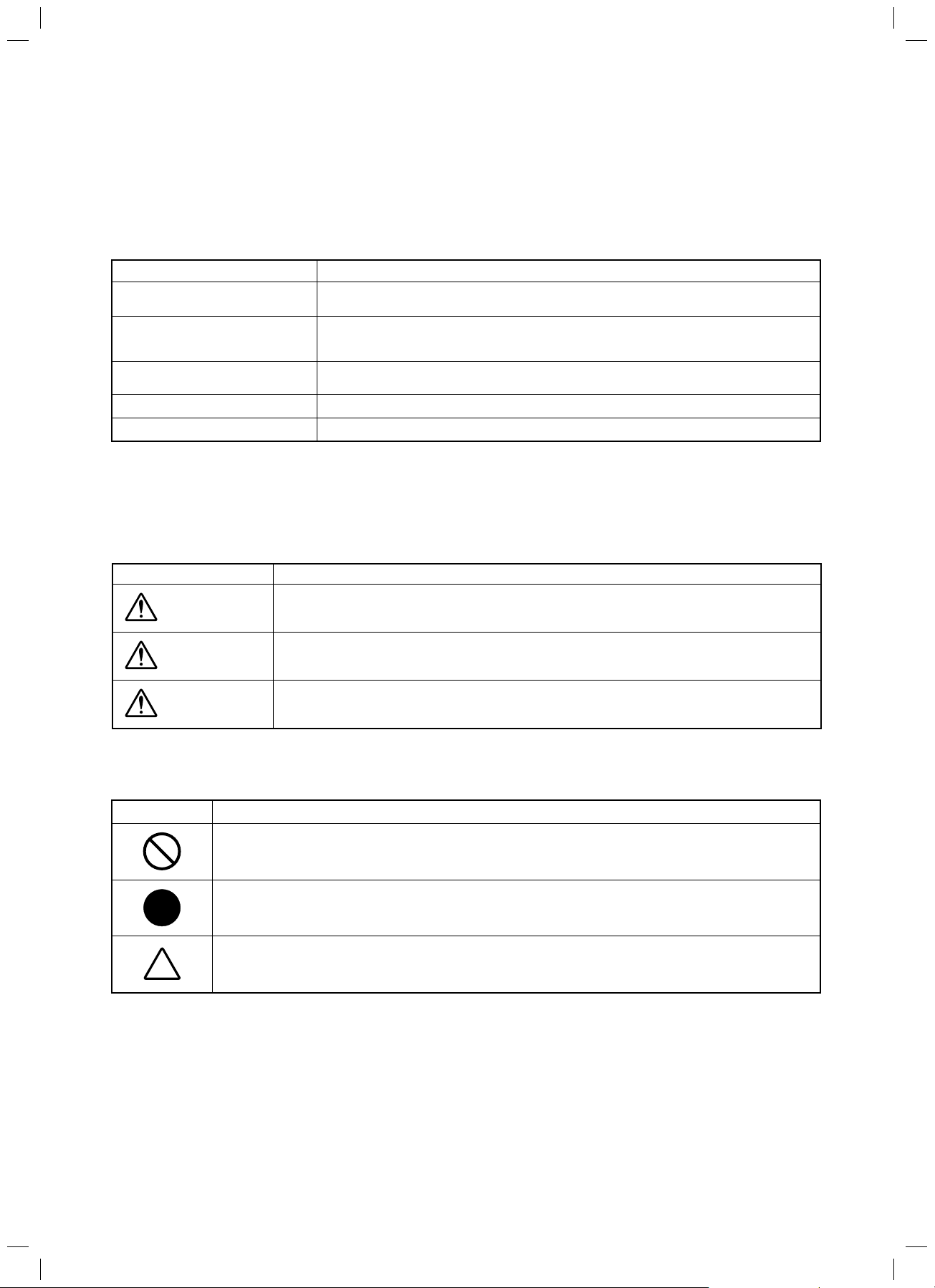
[Explanation of indications]
noitanalpxEnoitacidnI
DANGER
WARNING
CAUTION
Indicates contents assumed that an imminent danger causing a death or serious injury of
the repair engineers and the third parties when an incorrect work has been executed.
Indicates possibilities assumed that a danger causing a death or serious injury of the
repair engineers, the third parties, and the users due to troubles of the product after work
when an incorrect work has been executed.
Indicates contents assumed that an injury or property damage (*) may be caused on the
repair engineers, the third parties, and the users due to troubles of the product after work
when an incorrect work has been executed.
* Property damage: Enlarged damage concerned to property, furniture, and domestic animal / pet
[Explanation of illustrated marks]
noitanalpxEnoitacidnI
Indicates prohibited items (Forbidden items to do)
The sentences near an illustrated mark describe the concrete prohibited contents.
Indicates mandatory items (Compulsory items to do)
The sentences near an illustrated mark describe the concrete mandatory contents.
Indicates cautions (Including danger / warning)
The sentences or illustration near or in an illustrated mark describe the concrete cautious contents.
– 4 –
SVM-13085.indb 4SVM-13085.indb 4 12/24/13 10:56 AM12/24/13 10:56 AM
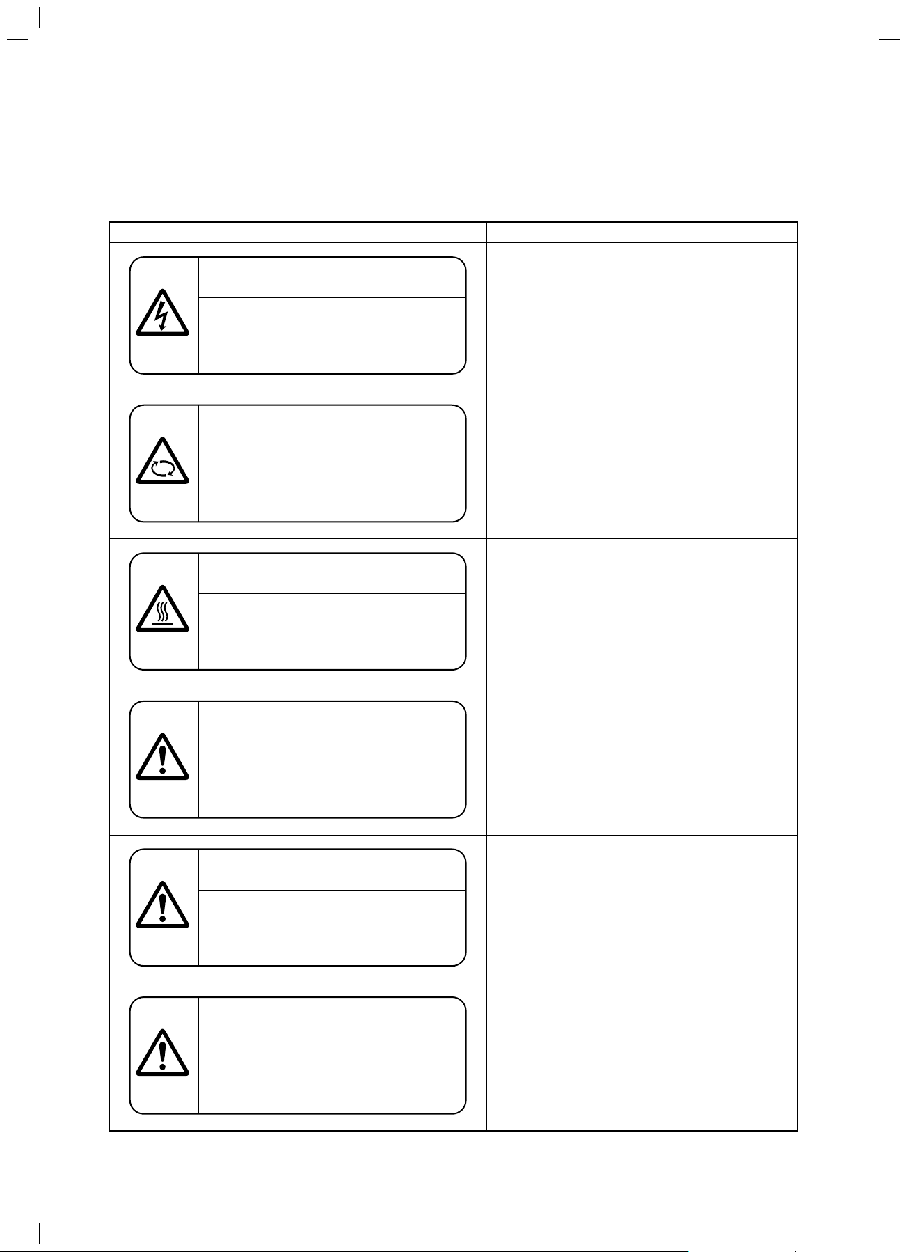
Warning Indications on the Air Conditioner Unit
[Confirmation of warning label on the main unit]
Confirm that labels are indicated on the specified positions
If removing the label during parts replace, stick it as the original.
FILE NO. SVM-13085
noitpircseDnoitacidni gninraW
WARNING
ELECTRICAL SHOCK HAZARD
Disconnect all remote electric
power supplies before servicing.
WARNING
Moving parts.
Do not operate unit with grille removed.
Stop the unit before the servicing.
CAUTION
High temperature parts.
You might get burned when removing
this panel.
WARNING
ELECTRICAL SHOCK HAZARD
Disconnect all remote electric power supplies
before servicing.
WARNING
Moving parts.
Do not operate unit with grille removed.
Stop the unit before the servicing.
CAUTION
High temperature parts.
You might get burned when removing this panel.
CAUTION
Do not touch the aluminium fins of the unit.
Doing so may result in injury.
CAUTION
BURST HAZARD
Open the service valves before the
operation, otherwise there might be the
burst.
CAUTION
Do not climb onto the fan guard.
Doing so may result in injury.
CAUTION
Do not touch the aluminium fins of the unit.
Doing so may result in injury.
CAUTION
BURST HAZARD
Open the service valves before the operation,
otherwise there might be the burst.
CAUTION
Do not climb onto the fan guard.
Doing so may result in injury.
– 5 –
SVM-13085.indb 5SVM-13085.indb 5 12/24/13 10:56 AM12/24/13 10:56 AM
FILE NO. SVM-13085
Precaution for Safety
The manufacturer shall not assume any liability for the damage caused by not observing the description of this
manual.
DANGER
Before carrying out the installation, maintenance, repair or removal work, be sure to set the circuit
breaker to the OFF position. Otherwise, electric shocks may result.
Before opening the electrical control box cover of the indoor unit or service panel of the outdoor
unit, set the circuit breaker to the OFF position. Failure to set the circuit breaker to the OFF position
may result in electric shocks through contact with the interior parts.
Only a qualified installer (1) or qualified service person (1) is allowed to remove the electrical
control box cover of the indoor unit or service panel of the outdoor unit and do the work required.
Tur n o f f
breaker.
Electric
shock
hazard
Before starting to repair the outdoor unit fan or fan guard, be absolutely sure to set the circuit
breaker to the OFF position, and place a "Work in progress" sign on the circuit breaker.
When cleaning the filter or other parts of the indoor unit, set the circuit breaker to OFF without fail, and
place a "Work in progress" sign near the circuit breaker before proceeding with the work.
When checking the electric parts, removing the cover of the electric parts box of Indoor Unit and/or
service panel of Outdoor Unit inevitably to determine the failure, use gloves to provide protection for
electricians, insulating shoes, clothing to provide protection from electric shock and
insulating tools. Be careful not to touch the live part. Electric shock may result. Only "Qualified
service person" is allowed to do this work.
Before operating the air conditioner after having completed the work, check that the electrical
parts box cover of the indoor unit and service panel of the outdoor unit are closed, and set the
circuit breaker to the ON position. You may receive an electric shock if the power is turned on
without first conducting these checks.
Prohibition
Stay on
protection
WARNING
When checking the electric parts, removing the cover of the electric parts box of Indoor Unit and/or
front panel of Outdoor Unit inevitably to determine the failure, put a sign "Do not enter" around the site
before the work. Failure to do this may result in third person getting electric shock.
Place a "Work in progress" sign near the circuit breaker while the installation, maintenance, repair
or removal work is being carried out.
There is a danger of electric shocks if the circuit breaker is set to ON by mistake.
When checking the electric parts, removing the cover of the electric parts box of Indoor Unit
and/or front panel of Outdoor Unit inevitably to determine the failure, put a sign "Do not enter"
around the site before the work. Failure to do this may result in third person getting electric shock.
If, in the course of carrying out repairs, it becomes absolutely necessary to check out the
electrical parts with the electrical parts box cover of one or more of the indoor units and the
service panel of the outdoor unit removed in order to find out exactly where the trouble lies, wear
insulated heat-resistant gloves, insulated boots and insulated work overalls, and take care to
avoid touching any live parts.
You may receive an electric shock if you fail to heed this warning. Only qualified service person
(1) is allowed to do this kind of work.
Before starting to repair the air conditioner, read carefully through the Service Manual, and repair
the air conditioner by following its instructions.
Only qualified service person (1) is allowed to repair the air conditioner.
Repair of the air conditioner by unqualified person may give rise to a fire, electric shocks, injury,
water leaks and/or other problems.
General
Only a qualified installer (1) or qualified service person (1) is allowed to carry out the electrical
work of the air conditioner.
Under no circumstances must this work be done by an unqualified individual since failure to carry
out the work properly may result in electric shocks and/or electrical leaks.
– 6 –
SVM-13085.indb 6SVM-13085.indb 6 12/24/13 10:56 AM12/24/13 10:56 AM
General
FILE NO. SVM-13085
Electrical wiring work shall be conducted according to law and regulation in the community and
Installation manual. Failure to do so may result in electrocution or short circuit.
To connect the electrical wires, repair the electrical parts or undertake other electrical jobs, wear
gloves to provide protection for electricians, insulating shoes and clothing to provide protection
from electric shocks. Failure to wear this protective gear may result in electric shocks.
Before opening the intake grille, set the circuit breaker to the OFF position. Failure to set the circuit
breaker to the OFF position may result in injury through contact with the rotation parts. Only a qualified
installer or qualified service person is allowed to remove the intake grille and do the work required.
Use wiring that meets the specifications in the Installation Manual and the stipulations in the local
regulations and laws. Use of wiring which does not meet the specifications may give rise to
electric shocks, electrical leakage, smoking and/or a fire.
Only a qualified installer (1) or qualified service person (1) is allowed to undertake work at heights using
a stand of 50 cm or more or to remove the electrical control box cover of the indoor unit to undertake work.
When working at heights, use a ladder which complies with the ISO 14122 standard, and follow
the procedure in the ladders instructions.
Also wear a helmet for use in industry as protective gear to undertake the work.
Before working at heights, put a sign in place so that no-one will approach the work location,
before proceeding with the work. Parts and other objects may fall from above, possibly injuring
a person below. While carrying out the work, wear a helmet for protection from falling objects.
Before opening the intake grille of the indoor unit or service panel of the outdoor unit, set the circuit breaker to
the OFF position. Failure to set the circuit breaker to the OFF position may result in electric shocks through
contact with the interior parts. Only a qualified installer or qualified service person is allowed to remove the
intake grille of the indoor unit or service panel of the outdoor unit and do the work required.
Check earth
wires.
Prohibition of
modification.
Do not touch the aluminum fin of the unit. You may injure yourself if you do so. If the fin must be
touched for some reason, first put on protective gloves and safety work clothing, and then proceed.
Use forklift to carry in the air conditioner units and use winch or hoist at installation of them.
When the air conditioner is to be transported, installed, maintained, repaired or removed, wear
protective gloves and 'safety' work clothing.
When transporting the air conditioner, do not take hold of the bands around the packing carton.
You may injure yourself if the bands should break.
When transporting the air conditioner, wear shoes with protective toe caps, protective gloves and
other protective clothing.
This air conditioner has passed the pressure test as specified in IEC 60335-2-40 Annex EE.
Before troubleshooting or repair work, check the earth wire is connected to the earth terminals of
the main unit, otherwise an electric shock is caused when a leak occurs.If the earth wire is not
correctly connected, contact an electric engineer for rework.
After completing the repair or relocation work, check that the ground wires are connected properly.
Connect earth wire. (Grounding work) Incomplete grounding causes an electric shock.
Do not connect ground wires to gas pipes, water pipes, and lightning rods or ground wires for
telephone wires.
Do not modify the products.Do not also disassemble or modify the parts.
It may cause a fire, electric shock or injury.
When any of the electrical parts are to be replaced, ensure that the replacement parts satisfy the
Use specified
par ts.
Do not bring
a child close to
the equipment.
specifications given in the Service Manual (o
Service Manual).
Use of any parts which do not satisfy the required specifications may give rise to electric shocks,smoking
and/or a fire.
If, in the course of carrying out repairs, it becomes absolutely necessary to check out the electrical parts
with the electrical parts box cover of one or more of the indoor units and the service panel of the outdoor
unit removed in order to find out exactly where the trouble lies, place "Keep out" signs around
the work site before proceeding.
Third-party individuals may enter the work site and receive electric shocks if this warning is not heeded.
r use the parts contained on the parts list in the
– 7 –
SVM-13085.indb 7SVM-13085.indb 7 12/24/13 10:56 AM12/24/13 10:56 AM

Insulating
measures
No fire
Refrigerant
FILE NO. SVM-13085
Connect the cut-off lead wires with crimp contact, etc, put the closed end side upward and then
apply a water-cut method, otherwise a leak or production of fire is caused at the users' side.
When performing repairs using a gas burner, replace the refrigerant with nitrogen gas because
the oil that coats the pipes may otherwise burn.
When repairing the refrigerating cycle, take the following measures.
Be attentive to fire around the cycle.
1)
When using a gas stove, etc, be sure to put out fire before work; otherwise the oil mixed with
refrigerant gas may catch fire.
Do not use a welder in the closed room.
2)
When using it without ventilation, carbon monoxid
Do not bring inflammables close to the refrigerant cycle, otherwise fire of the welder may catch
3)
e poisoning may be caused.
the inflammables.
The refrigerant used by this air conditioner is the R410A.
Check the used refrigerant name and use tools and materials of the parts which match with it.
For the products which use R410A refrigerant, the refrigerant name is indicated at a position on
the outdoor unit where is easy to see.
To prevent miss-charging, the route of the service port is changed from one of the former R22.
Do not use any refrigerant different from the one specified for complement or replacement.
Otherw
ise, abnormally high pressure may be generated in the refrigeration cycle, which may
result in a failure or explosion of the product or an injury to your body.
For an air conditioner which uses R410A, never use other refrigerant than R410A.
For an air conditioner which uses other refrigerant (R22, etc.), never use R410A.
If different types of refrigerant are mixed, abnormal high pressure generates in the refrigerating
cycle and an injury due to breakage may be caused.
Do not charge refrigerant additionally.
If charging refrigerant additionally when refrigerant gas leaks, the refrigerant composition in the
refrigerating cycle changes resulted in change of air conditioner characteristics or refrigerant over
the specified standard amount is charged and an abnormal high pressure is applied to the inside
of the refrigerating cycle resu
lted in cause of breakage or injury.
Therefore if the refrigerant gas leaks, recover the refrigerant in the air conditioner, execute
vacuuming, and then newly recharge the specified amount of liquid refrigerant.
In this time, never charge the refrigerant over the specified amount.
Assembly/
Cabling
Insulator
check
Ventilation
When recharging the refrigerant in the refrigerating cycle, do not mix the refrigerant or air other
than R410A into the specified refrigerant.
If air or others is mixed with the refrigerant, abnormal high pressure gener
ates in the refrigerating
cycle resulted in cause of injury due to breakage.
After installation work, check the refrigerant gas does not leak.
If the refrigerant gas leaks in the room, poisonous gas generates when gas touches to fire such
as fan heater, stove or cocking stove though the refrigerant gas itself is innocuous.
Never recover the refrigerant into the outdoor unit.
When the equipment is moved or repaired, be sure to recover the refrigerant with recovering device.
The refrigerant cannot be recovered in the outdoor unit; otherwise a serious accident such as
breakage or injury is caused.
After repair work, surely assemble the disassembled parts, and connect and lead the removed
wires as before.
Perform the work so that the cabinet or panel does not catch the inner wires.
If incorrect assembly or incorrect wire connection was done, a disaster such as a leak or fire is
caused at user's side.
After the work has finished, be sure to use an insulation tester set (500V Megger) to check the
resistance is 1M
Ω or more between the charge section and the non-
charge metal section
(Earth position).
If the resistance value is low, a disaster such as a leak or electric shock is caused at user's side.
When the refrigerant gas leaks during work, execute ventilation.
If the refrigerant gas touches to a fire, poisonous gas generates.
A case of leakage of the refrigerant and the closed room full with gas is dangerous because a
shortage of oxygen occurs. Be sure to execute ventilation.
If refrigerant gas has
leaked during the installation work, ventilate the room immediately.
If the leaked refrigerant gas comes in contact with fire, noxious gas may generate.
After installation work, check the refrigerant gas does not leak. If the refrigerant gas leaks in the
room, poisonous gas generates when gas touches to fire such as fan heater, stove or cocking
stove though the refrigerant gas itself is innocuous.
– 8 –
SVM-13085.indb 8SVM-13085.indb 8 12/24/13 10:56 AM12/24/13 10:56 AM
Compulsion
Check after
repair
FILE NO. SVM-13085
When the refrigerant gas leaks, find up the leaked position and repair it surely.
If the leaked position cannot be found up and the repair work is interrupted, pump-down and
tighten the service valve, otherwise the refrigerant gas may leak into the room.
The poisonous gas generates when gas touches to fire such as fan heater, stove or cocking stove
though the refrigerant gas itself is innocuous.
When installing equipment which includes a large amount of charged refrigerant such as a multi
air conditioner in a sub-room, it is necessary that the density does not the limit even if the
refrigerant leaks.
If the refrigerant leaks and exceeds the limit density, an accident of shortage of oxygen is caused.
Tighten the flare nut with a torque wrench in the specified manner.
Excessive tighten of the flare nut may cause a crack in the flare nut after a long period, which may
result in refrigerant leakage.
Nitrogen gas must be u
sed for the airtight test.
The charge hose must be connected in such a way that it is not slack.
For the installation/moving/reinstallation work, follow to the Installation Manual.
If an incorrect installation is done, a trouble of the refrigerating cycle, water leak, electric shock or
fire is caused.
Once the repair work has been completed, check for refrigerant leaks, and check the insulation
resistance and water drainage.
Then perform a trial run to check that the air conditioner is running properly.
After repair work has finished, check there is no trouble. If check is not executed, a fire, electric
shock or injury may be caused. For a check, turn off the power breaker.
After repair work (installation of front panel and cabinet) has finished, execute a test run to check
there is no generation of smoke or abnormal sound.
If check is not executed, a fire or an electric shock is caused. Before test run, install the front
panel and cabinet.
Do not
operate the
unit with the
valve closed.
Check after
reinstallation
Check the following matters before a test run after repairing piping.
Connect the pipes surely and there is no leak of refrigerant.
The valve is opened.
Running the compressor under conditi
on that the valve closes causes an abnormal high
pressure resulted in damage of the parts of the compressor and etc. and moreover if there is
leak of refrigerant at connecting section of pipes, the air is suctioned and
causes further
abnormal high pressure resulted in burst or injury.
Only a qualified installer (1) or qualified service person (1) is allowed to relocate the air
conditioner. It is dangerous for the air conditioner to be relocated by an unqualified individual
since a fire, electric shocks, injury, water leakage, noise and/or vibration may result.
Check the following items after reinstallation.
1) The earth wire is correctly connected.
2) The
power cord is not caught in the product.
3) There is no inclination or unsteadiness and the installation is stable.
If check is not executed, a fire, an electric shock or an injury is caused.
When carrying out the pump-down work shut down the compressor before disconnecting the
refrigerant pipe.
Disconnecting the refrigerant pipe with the service valve left open and the compressor still
operating will cause air, etc. to be sucked in, raising the pressure inside the refrigeration cycle to
an abnormally high level, and possibly resulting in reputing, injury, etc.
When the service panel of the outdoor unit is to be opened in order for th
e compressor or the
area around this part to be repaired immediately after the air conditioner has been shut down, set
the circuit breaker to the OFF position, and then wait at least 10 minutes before opening the
service panel.
If you fail to heed this warning, you will run the risk of burning yourself because the compressor
pipes and other parts will be very hot to the touch. In addition, before proceeding with the repair
work, wear the kind of insulated heat-resistant gloves designed to protect electricians.
Cooling check
When the service panel of the outdoor unit is to be opened in order for the fan motor, reactor,
inverter or the areas arou
nd these parts to be repaired immediately after the air conditioner has
been shut down, set the circuit breaker to the OFF position, and then wait at least 10 minutes
before opening the service panel.
If you fail to heed this warning, you will run the risk of burning yourself because the fan motor,
reactor, inverter heat sink and other parts will be very hot to the touch.
In addition, before proceeding with the repair work, wear the kind of insulated heat-resistant
gloves designed to protect electricians.
– 9 –
SVM-13085.indb 9SVM-13085.indb 9 12/24/13 10:56 AM12/24/13 10:56 AM
FILE NO. SVM-13085
Only a qualified installer or service person is allowed to do installation work. Inappropriate
installation may result in water leakage, electric shock or fire.
Before starting to install the air conditioner, read carefully through the Installation Manual, and
follow its instructions to install the air conditioner.
If the unit is installed in a small room, take appropriate measures to prevent the refrigerant from
exceeding the limit concentration even if it leaks. Consult the dealer from whom you purchased
the air conditioner when you implement the measures. Accumulation of highly-concentrated
refrigerant may cause an oxygen deficiency accident.
Do not install the air conditioner in a location that may be subject to a risk of expire to a
Installation
combustible gas.
If a combustible gas leaks and becomes concentrated around the unit, a fire may occur.
Install the indoor unit at least 2.5 m above the floor level since otherwise the users may injure
themselves or receive electric shocks if they poke their fingers or other objects into the indoor unit
while the air conditioner is running.
Install a circuit breaker that meets the specifications in the installation manual and the stipulations
in the local regulations and laws.
Install the circuit breaker where it can be easily accessed by the agent.
Do not place any combustion appliance in a place where it is directly exposed to the wind of air
conditioner, otherwise it may cause imperfect combustion.
Explanations given to user
If you have discovered that the fan grille is damaged, do not approach the outdoor unit but set the circuit breaker
to the OFF position, and contact a qualified service person to have the repairs done.
Do not set the circuit breaker to the ON position until the repairs are completed.
Relocation
s Only a qualified installer (*1) or qualified service person (*1) is allowed to relocate the air conditioner.
It is dangerous for the air conditioner to be relocated by an unqualified individual since a fire, electric shocks,
injury, water leakage, noise and / or vibration may result.
s When carrying out the pump-down work shut down the compressor before disconnecting the refrigerant pipe.
Disconnecting the refrigerant pipe with the service valve left open and the compressor still operating will cause
air, etc. to be sucked in, raising the pressure inside the refrigeration cycle to an abnormally high level, and
possibly resulting in reputing, injury, etc.
(*1) Refer to the “Definition of Qualified Installer or Qualified Service Person”
– 10 –
SVM-13085.indb 10SVM-13085.indb 10 12/24/13 10:56 AM12/24/13 10:56 AM

Declaration of Conformity
Manufacturer: TOSHIBA CARRIER (THAILAND) CO., LTD.
144 / 9 Moo 5, Bangkadi Industrial Park, Tivanon Road,
Amphur Muang, Pathumthani 12000, Thailand
Authorized Nick Ball
Representative/TCF holder: Toshiba EMEA Engineering Director
Toshiba Carrier UK Ltd.
Porsham Close, Belliver Industrial Estate,
PLYMOUTH, Devon, PL6 7DB.
United Kingdom
Hereby declares that the machinery described below:
Generic Denomination: Air Conditioner
Model/type: MMC-AP0157HP-E MMC-AP0157HP-TR
MMC-AP0187HP-E MMC-AP0187HP-TR
MMC-AP0247HP-E MMC-AP0247HP-TR
MMC-AP0277HP-E MMC-AP0277HP-TR
MMC-AP0367HP-E MMC-AP0367HP-TR
MMC-AP0487HP-E MMC-AP0487HP-TR
MMC-AP0567HP-E MMC-AP0567HP-TR
FILE NO. SVM-13085
Commercial name: Super Modular Multi System Air Conditioner
Super Heat Recovery Multi System Air Conditioner
MiNi-Super Modular Multi System Air Conditioner (MiNi-SMMS
series)
Complies with the provisions of the “Machinery” Directive (Directive 2006/42/EC) and the regulations
transposing into national law.
Complies with the provisions of the following harmonized standard:
EN 378-2: 2008 + A2: 2012
Note: This declaration becomes invalid if technical or operational modifications are introduced without the
manufacturer’s consent.
– 11 –
SVM-13085.indb 11SVM-13085.indb 11 12/24/13 10:56 AM12/24/13 10:56 AM
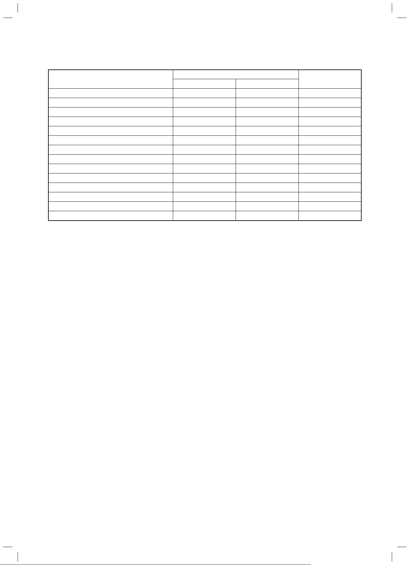
Specifications
∗ ∗
∗ ∗
∗ ∗
∗ ∗
∗ ∗
∗ ∗
∗ ∗
∗ ∗
∗ ∗
∗ ∗
∗ ∗
∗ ∗
∗ ∗
∗ ∗
∗
FILE NO. SVM-13085
MMC-AP0157HP-E
MMC-AP0187HP-E
MMC-AP0247HP-E
MMC-AP0277HP-E
MMC-AP0367HP-E
MMC-AP0487HP-E
MMC-AP0567HP-E
MMC-AP0157HP-TR
MMC-AP0187HP-TR
MMC-AP0247HP-TR
MMC-AP0277HP-TR
MMC-AP0367HP-TR
MMC-AP0487HP-TR
MMC-AP0567HP-TR
: Under 70 dBA
Model
Sound power level (dBA)
Cooling Heating
Weight (kg)
23
23
29
29
35
35
35
23
23
29
29
35
35
35
– 12 –
SVM-13085.indb 12SVM-13085.indb 12 12/24/13 10:56 AM12/24/13 10:56 AM

FILE NO. SVM-13085
• R410A Refrigerant
This air conditioner adopted HFC type refrigerant (R410A) which does not deplete the ozone layer.
1. Safety Caution Concerned to R410A Refrigerant
The pressure of R410A is high 1.6 times of that of the former refrigerant (R22).
Accompanied with change of refrigerant, the refrigerating oil has been also changed.
Therefore, be sure that water, dust, the former refrigerant or the former refrigerating oil is not mixed into the
refrigerating cycle of the air conditioner with R410A refrigerant during installation work or service work.
If an incorrect work or incorrect service is performed, there is a possibility to cause a serious accident.
Use the tools and materials exclusive to R410A to purpose a safe work.
2. Cautions on Installation/Service
1) Do not mix the other refrigerant or refrigerating oil.
For the tools exclusive to R410A, shapes of all the joints including the service port differ from those of
the former refrigerant in order to prevent mixture of them.
2) As the use pressure of the R410A refrigerant is high, use material thickness of the pipe and tools which
are specified for R410A.
3) In the installation time, use clean pipe materials and work with great attention so that water and others do
not mix in because pipes are affected by impurities such as water, oxide scales, oil, etc.
Use the clean pipes.
Be sure to brazing with flowing nitrogen gas. (Never use gas other than nitrogen gas.)
4) For the earth protection, use a vacuum pump for air purge.
5) R410A refrigerant is azeotropic mixture type refrigerant.
Therefore use liquid type to charge the refrigerant. (If using gas for charging, composition of the
refrigerant changes and then characteristics of the air conditioner change.)
3. Pipe Materials
For the refrigerant pipes, copper pipe and joints are mainly used.
It is necessary to select the most appropriate pipes to conform to the standard.
Use clean material in which impurities adhere inside of pipe or joint to a minimum.
1) Copper pipe
<Piping>
The pipe thickness, flare finishing size, flare nut and others differ according to a refrigerant type.
When using a long copper pipe for R410A, it is recommended to select “Copper or copper-base pipe
without seam” and one with bonded oil amount 40mg/10m or less.
Also do not use crushed, deformed, discolored (especially inside) pipes.
(Impurities cause clogging of expansion valves and capillary tubes.)
<Flare nut>
Use the flare nuts which are attached to the air conditioner unit.
2) Joint
The flare joint and socket joint are used for joints of the copper pipe.
The joints are rarely used for installation of the air conditioner. However clear impurities when using them.
– 13 –
SVM-13085.indb 13SVM-13085.indb 13 12/24/13 10:56 AM12/24/13 10:56 AM
FILE NO. SVM-13085
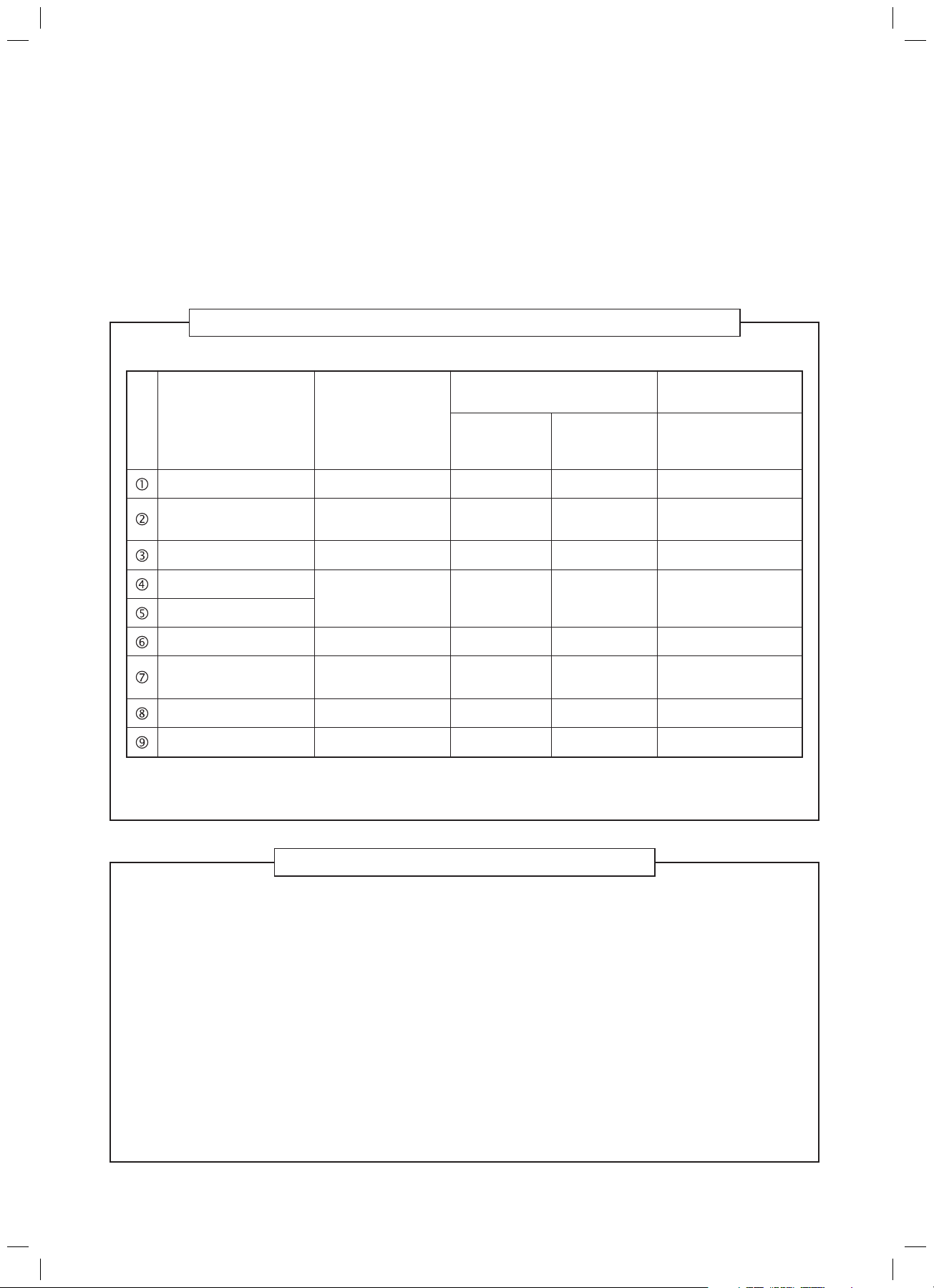
4. Tools
1. Required Tools for R410A
Mixing of different types of oil may cause a trouble such as generation of sludge, clogging of capillary,
etc. Accordingly, the tools to be used are classified into the following three types.
1) Tools exclusive for R410A (Those which cannot be used for conventional refrigerant (R22))
2) Tools exclusive for R410A, but can be also used for conventional refrigerant (R22)
3) Tools commonly used for R410A and for conventional refrigerant (R22)
The table below shows the tools exclusive for R410A and their interchangeability.
Tools exclusive for R410A (The following tools for R410A are required.)
Tools whose specifications are changed for R410A and their interchangeability
No. Used tool
Flare tool
Copper pipe gauge for
adjusting projection margin
Torque wrench
Gauge manifold
Charge hose
Vacuum pump adapter
Electronic balance for
refrigerant charging
Refrigerant cylinder
Leakage detector
Usage
Pipe flaring
Flaring by conventional
flare tool
Tightening of flare nut
Evacuating, refrigerant
charge, run check, etc.
Vacuum evacuating
Refrigerant charge
Refrigerant charge
Gas leakage check
air conditioner installation
R410A
Existence of Whether conven-
new equipment tional equipment
for R410A can be used
Yes *(Note)
Yes *(Note)
Ye s N o
Ye s N o
Ye s N o
Ye s Ye s
Ye s N o
Ye s N o
Conventional air
conditioner installation
Whether conventional
equipment can be used
Ye s
*(Note)
No
No
Ye s
Ye s
No
Ye s
(Note) When flaring is carried out for R410A using the conventional flare tools, adjustment of projection
margin is necessary. For this adjustment, a copper pipe gauge, etc. are necessary.
General tools (Conventional tools can be used.)
In addition to the above exclusive tools, the following equipments which serve also for R22 are necessary
as the general tools.
1) Vacuum pump. Use vacuum pump by
attaching vacuum pump adapter. 7) Screwdriver (+, –)
hcnerw yeknoM ro rennapS)8hcnerw euqroT)2
llird eroc eloH)9rettuc epiP)3
nogaxeH)01remaeR)4
)mm4 edis etisoppO( hcnerw
erusaem epaT)11redneb epiP)5
was lateM)21laiv leveL)6
Also prepare the following equipments for other installation method and run check.
talusnI)3retem pmalC)1
)reggeM( retset ecnatsiser noi
epocsortcelE)4retemomrehT)2
– 14 –
SVM-13085.indb 14SVM-13085.indb 14 12/24/13 10:56 AM12/24/13 10:56 AM
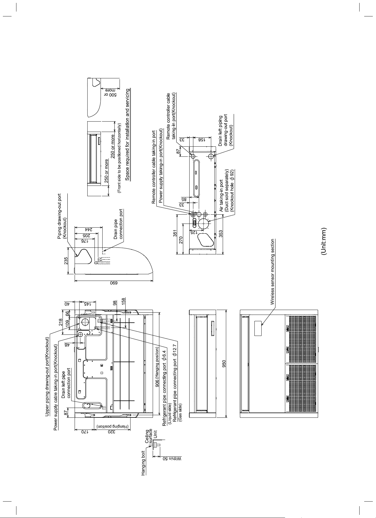
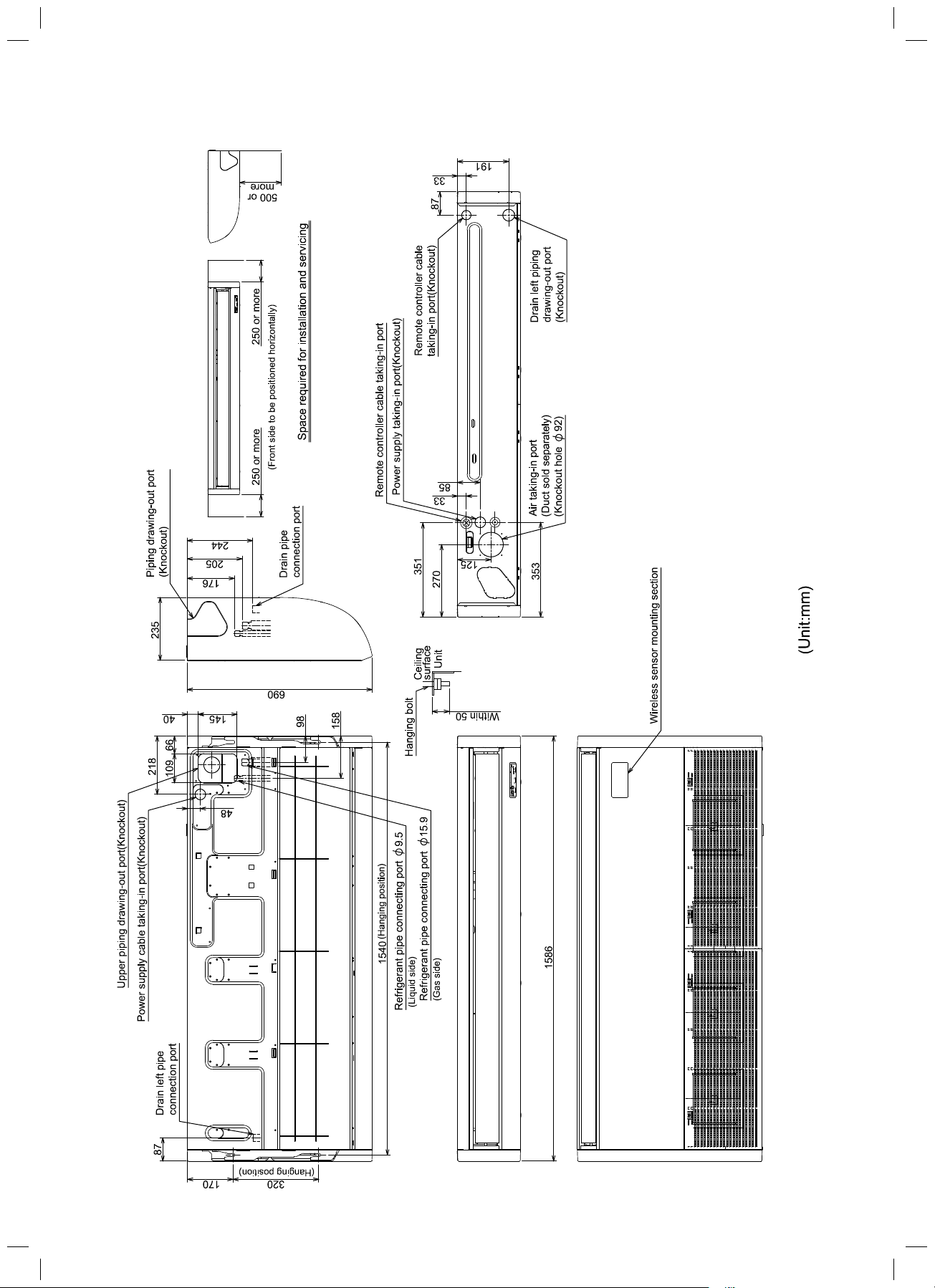
1. CONSTRUCTION VIEWS (EXTERNAL VIEWS)
1-1. Indoor Unit
MMC-AP0157HP*, AP0187HP*
FILE NO. SVM-13085
– 15 –
SVM-13085.indb 15SVM-13085.indb 15 12/24/13 10:56 AM12/24/13 10:56 AM
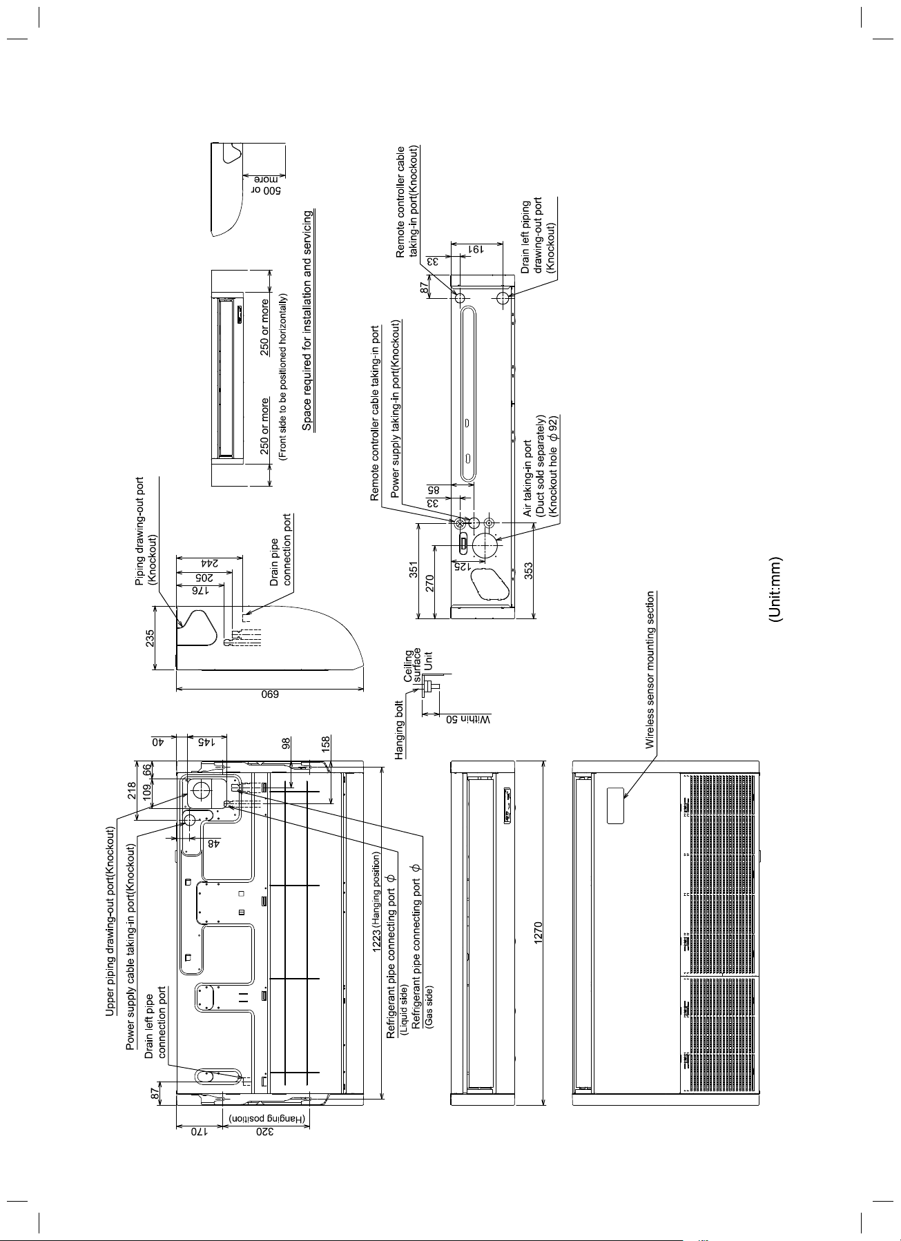
MMC-AP0247HP*, AP0277HP*
FILE NO. SVM-13085
12.7
6.4
– 16 –
SVM-13085.indb 16SVM-13085.indb 16 12/24/13 10:56 AM12/24/13 10:56 AM
MMC-AP0367HP* to AP0567HP*
FILE NO. SVM-13085
– 17 –
SVM-13085.indb 17SVM-13085.indb 17 12/24/13 10:56 AM12/24/13 10:56 AM

㻰㼞㼍㼕㼚㻌㼜㼡㼙㼜
㻔㻻㼜㼠㼕㼛㼚㻕
㼗㼕㼠㻌㼍㼠㼠㼍㼏㼔㼑㼐
2. WIRING DIAGRAM
㻔㻾㻱㻰㻕
FILE NO. SVM-13085
㻲㼡㼟㼑
㻯㼛㼚㼚㼑㼏㼠㼛㼞
㻼㼍㼞㼠㼟㻌㻺㼍㼙㼑
㻲㼍㼚㻌㻹㼛㼠㼛㼞
㼀㼑㼞㼙㼕㼚㼍㼘㻌㻮㼘㼛㼏㼗
㻵㼚㼐㼛㼛㼞㻌㼠㼑㼙㼜㻌㼟㼑㼚㼟㼛㼞
㻲㼘㼛㼍㼠㻌㻿㼣㼕㼠㼏㼔
㼀㼑㼙㼜㻌㼟㼑㼚㼟㼛㼞
㻸㼛㼡㼢㼑㼞㻌㻹㼛㼠㼛㼞
㻰㼞㼍㼕㼚㻌㻼㼡㼙㼜㻌㻹㼛㼠㼛㼞
㻿㼥㼙㼎㼛㼘
㻯㻺㻖㻖
㼀㻮㻜㻝㻘㻜㻞
㼀㻭
㻲㻹
㻲㻜㻝
㼒㼟㻰㻹㻸㻹
㼀㻯㻝㻘㻞㻘㼀㻯㻶
㻔㻮㻸㼁㻕
㻿㼛㼘㼐
㼟㼑㼜㼍㼠㼍㼠㼑㼘㼥
㻔㻻㼜㼠㼕㼛㼚㻕
㻰㼞㼍㼕㼚㻌㼜㼡㼙㼜㻌㼗㼕㼠
㻾㻱㻰㻦㻾㻱㻰
㼃㻴㻵㻦㼃㻴㻵㼀㻱
㻯㻻㻸㻻㻾
㻔㼃㻴㻵㻕
㻵㻺㻰㻵㻯㻭㼀㻵㻻㻺
㼅㻱㻸㻦㼅㻱㻸㻸㻻㼃
㻮㼁㻸㻦㻮㼁㻸㻱
㻮㻸㻷㻦㻮㻸㻭㻯㻷
㻳㻾㻺㻦㻳㻾㻱㻱㻺
㻮㻾㼃㻦㻮㻾㻻㼃㻺
㻔㻴㼕㼓㼔㻌㼏㼑㼘㼘㼕㼚㼓㻌㼞㼑㼟㼔㼡㼒㼒㼘㼕㼚㼓㻕
㻔㼅㻱㻸㻕
㼟㼡㼜㼜㼘㼥
㻼㼛㼣㼑㼞
㼏㼕㼞㼏㼡㼕㼠
㻯㼛㼚㼠㼞㼛㼘㻌㻼㻚㻯㻚㻌㻮㼛㼍㼞㼐
㻔㼃㻴㻵㻕
㻔㻮㻸㻷㻕
㻔㼅㻱㻸㻕
㼕㼚㼐㼕㼏㼍㼠㼑㼟㻌㼠㼔㼑㻌㼏㼛㼚㼚㼑㼏㼠㼕㼛㼚㻌㼠㼑㼞㼙㼕㼚㼍㼘㻚
㼕㼚㼐㼕㼏㼍㼠㼑㼟㻌㼠㼔㼑㻌㼏㼛㼚㼚㼑㼏㼠㼛㼞㻌㼛㼚㻌㼠㼔㼑㻌㼏㼛㼚㼠㼞㼛㼘㻌㻼㻚㻯㻚㻌㼎㼛㼍㼞㼐㻚
㻞㻚㻌㻌㻌㻌㻌㻌㻌㻌㻌㼕㼚㼐㼕㼏㼍㼠㼑㼟㻌㼠㼔㼑㻌㼠㼑㼞㼙㼕㼚㼍㼘㻌㼎㼘㼛㼏㼗㻚
㻌㻌㻌㻸㼛㼚㼓㻌㼐㼍㼟㼔㼑㼐㻌㼟㼔㼛㼞㼠㻌㼐㼍㼟㼔㼑㼐㻌㼘㼕㼚㼑㻌㼕㼚㼐㼕㼏㼍㼠㼑㻌㼠㼔㼑㻌㼍㼏㼏㼑㼟㼟㼛㼞㼕㼑㼟㻚㻌
㻝㻚㻌㻮㼞㼛㼗㼑㼚㻌㼘㼕㼚㼑㻌㼕㼚㼐㼕㼏㼍㼠㼑㼟㻌㼠㼔㼑㻌㼑㼕㼞㼕㼚㼓㼍㼠㻌㼟㼕㼠㼑㻚
㻔㻮㻸㼁㻕
㻔㻮㻸㼁㻕
㻟㻚㻌㻌㻌㻌㻌㻌㻌㻌㻌㼕㼚㼐㼕㼏㼍㼠㼑㼟㻌㼠㼔㼑㻌㼜㼞㼛㼠㼑㼏㼠㼕㼛㼚㻌㼓㼞㼛㼡㼚㼐㼟㻚
㻠㻚㻌㻌㻌㻌㻌㻌㻌㻌㻌㻌㻌㼕㼚㼐㼕㼏㼍㼠㼑㼟㻌㼠㼔㼑㻌㼏㼛㼚㼠㼞㼛㼘㻌㻼㻚㻯㻚㻌㼎㼛㼍㼞㼐㻚
㻔㻮㻸㻷㻕
㻮㻸㼁
㻮㻸㻷
㻮㻸㻷
㻯㼛㼚㼠㼞㼛㼘㼘㼑㼞
㼃㼕㼞㼑㼐㻌㻾㼑㼙㼛㼠㼑㻻㼡㼠㻌㼐㼛㼛㼞㻌㼡㼚㼕㼠
㻾㻱㻰
㼃㻴㻵
㻯㻺㻞㻞
㻮㻸㻷
㻮㻸㼁
㼟㼏㼞㼑㼣
㻱㼍㼞㼠㼔
㼟㼏㼞㼑㼣
㻱㼍㼞㼠㼔
– 18 –
SVM-13085.indb 18SVM-13085.indb 18 12/24/13 10:56 AM12/24/13 10:56 AM
3. PARTS RATING
FILE NO. SVM-13085
Parts name Model Specifi cations
ICF-340WD94-1 -
Fan motor
Louver motor MP24Z3T Pulse motor EFM-MD12TF -
Pulse motor valve
TA sensor - 518 mm
TC1 sensor - Ø4 mm, 1000 mm
TC2 sensor - Ø6 mm, 1000 mm
TCJ sensor - Ø6 mm, 1000 mm
ICF-340WD94-2 - - ICF-340WD139-1 - ----
EFM-40YGTF EFM-40YGTCTH - - EFM-60YGTCTH - - - - -
MMC-AP***7HP*
015 018 024 027 036 048 056
- ---
-----
---
---
– 19 –
SVM-13085.indb 19SVM-13085.indb 19 12/24/13 10:56 AM12/24/13 10:56 AM
FILE NO. SVM-13085
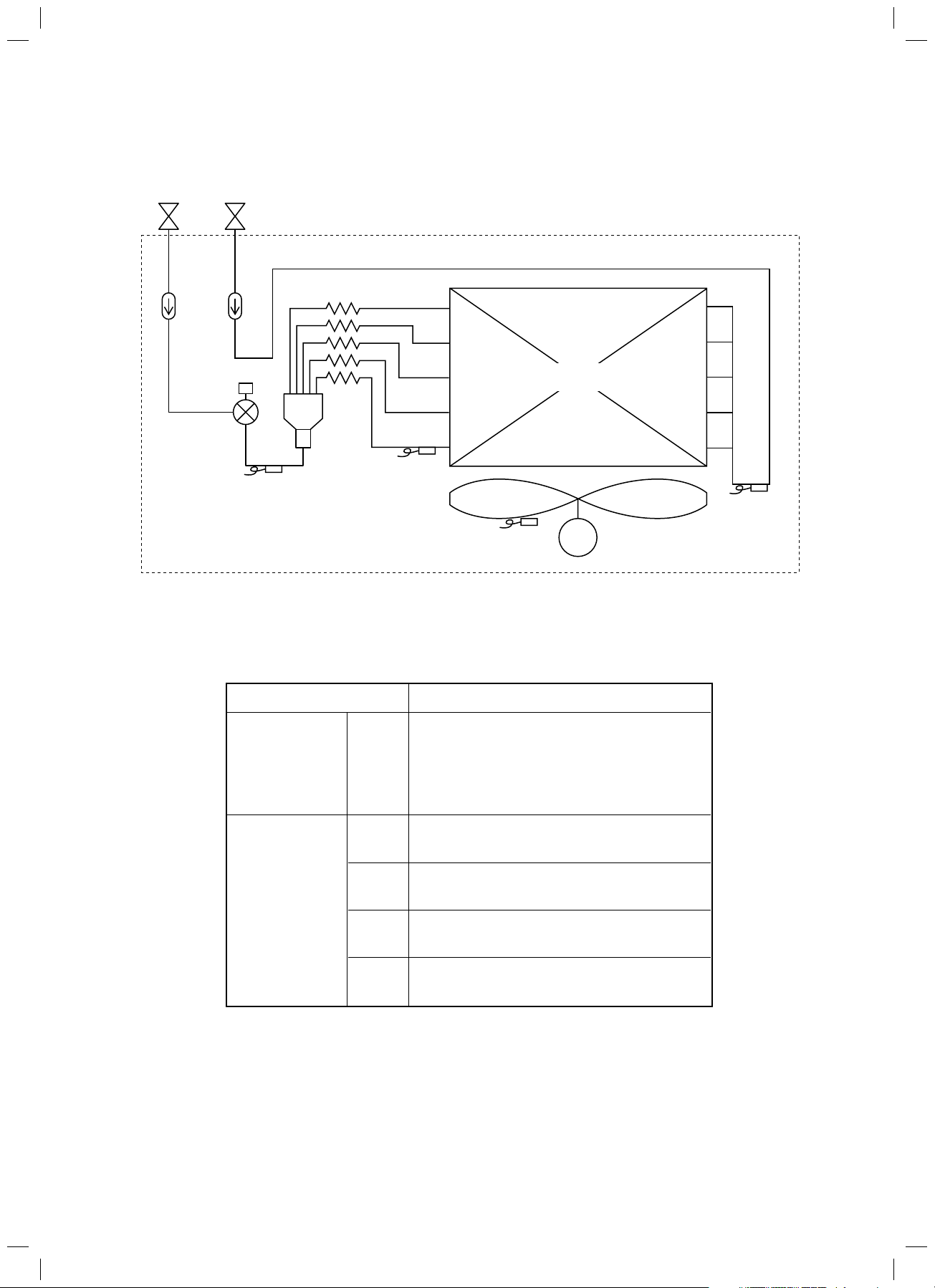
4. REFRIGERATION CYCLE DIAGRAM
Gas sideLiquid side
Strainer
Pulse Motor
Valve (PMV)
Sensor
(TC2)
Capillary tubes
Strainer
Sensor
(TCJ)
Heat exchanger
at indoor side
Fan
Sensor
(TA)
Sensor
(TC1)
M
Fan motor
Functional part name
Pulse Motor Valve PMV
Temp. sensor 1. TA
2. TC1
3. TC2
4. TCJ
Functional outline
(Connector CN82 (6P): Blue)
1) Controls super heat in cooling operation
2) Controls under cool in heating operation
3) Recovers refrigerant oil in cooling operation
4) Recovers refrigerant oil in heating operation
(Connector CN104 (2P): Yellow)
1) Detects indoor suction temperature
(Connector CN100 (3P): Brown)
1) Controls PMV super heat in cooling operation
(Connector CN101 (2P): Black)
1) Controls PMV under cool in heating operation
(Connector CN102 (2P): Red)
1) Controls PMV super heat in cooling operation
– 20 –
SVM-13085.indb 20SVM-13085.indb 20 12/24/13 10:56 AM12/24/13 10:56 AM
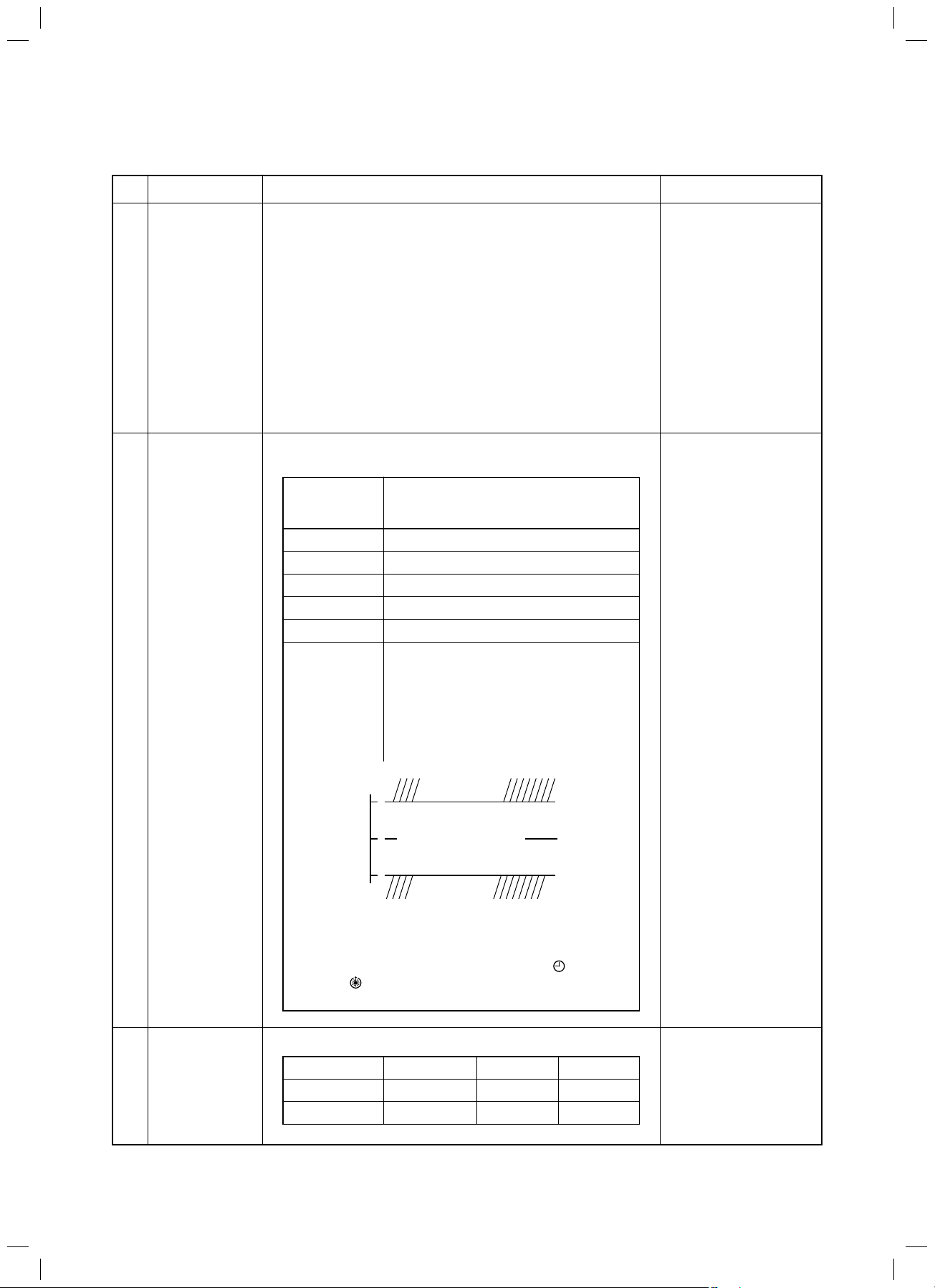
5-1. Control Specifications
FILE NO. SVM-13085
5. CONTROL OUTLINE
No.
1
When power
supply is reset
2
Operation
mode selection
Item
Outline of specifications
1) Distinction of outdoor unit
When the power supply is reset, the outdoors are
distinguished and the control is selected according to the
distinguished result.
2) Setting of indoor fan speed and existence of air direction
adjustment
Based on EEPROM data, select setting of the indoor fan
speed and the existence of air direction adjustment.
3) If resetting the power supply during occurrence of a
trouble, the check code is once cleared. After ON/OFF
button of the remote controller was pushed and the
operation was resumed, if the abnormal status continues,
the check code is again displayed on the remote controller.
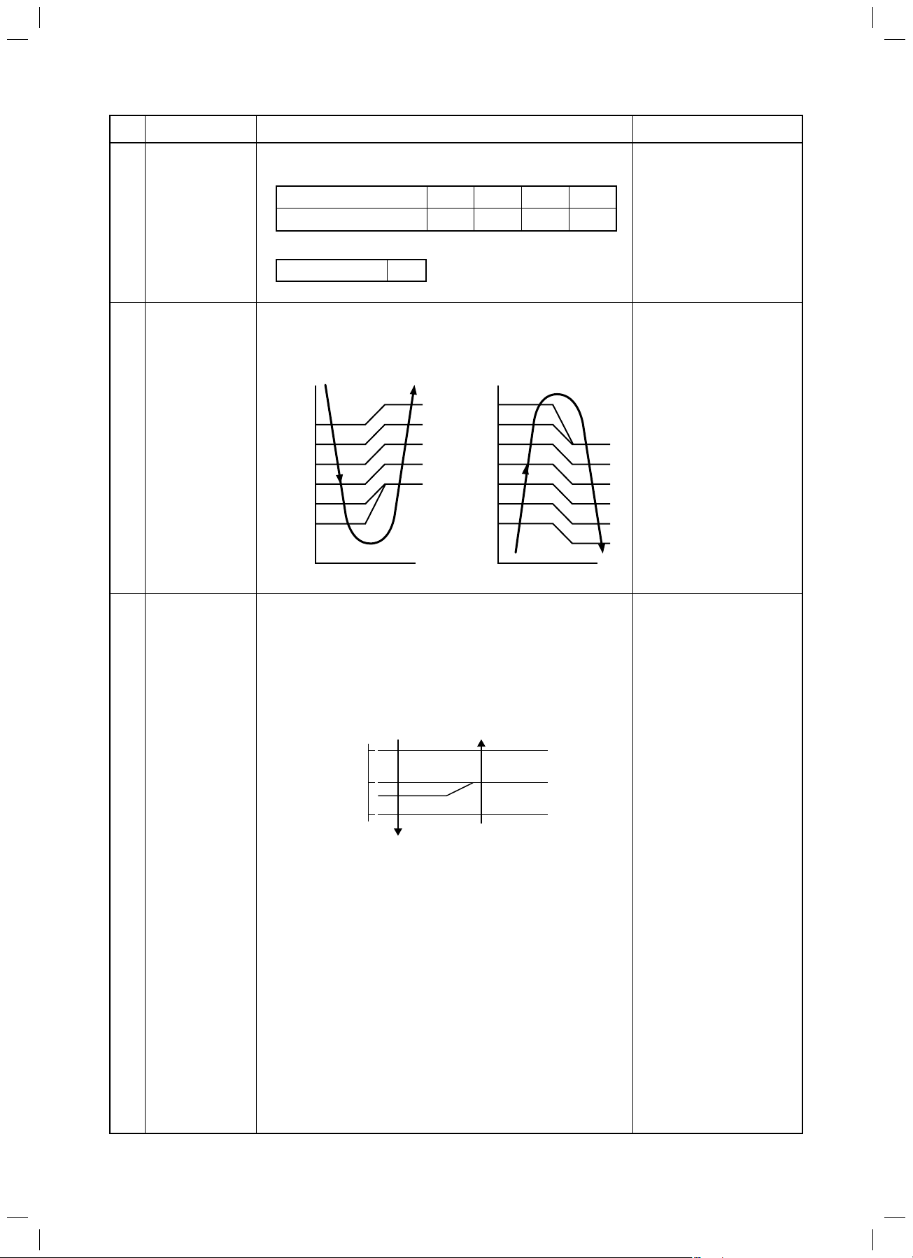
1) Based on the operation mode selecting command from the
remote controller, the operation mode is selected.
Remote
controller
command
STOP
FAN
COOL
DRY
HEAT
AUTO
(SHRM only)
Air conditioner stops.
Fan operation
Cooling operation
Dry operation
Heating operation
s Ta and Ts automatically select COOL/
HEAT operation mode for operation.
s The operation is performed as shown in
the following figure according to Ta value
at the first time only.
(In the range of Ts – 1 < Ta < Ts + 1,
Cooling thermo. OFF (Fan) / Setup air
volume operation continues.)
Control outline
Remarks
Ta: Room temp.
Ts: Setup temp.
3
Room temp.
control
Cooling
+1.0
Ta
Ts
(°C)
–1.0
∗ In the SMMS-i and Mini-SMMS, the automatic mode
cannot be selected. While a wireless remote controller is
used, the mode is notified by “Pi Pi” (two times) receiving
sound and the alternate flashing of [TIMER
[READY To clear the alternate flashing, change the
mode on the wireless remote controller.
].
thermo. ON
Cooling thermo. OFF
(at the first time only)
Heating
thermo. ON
] and
1) Adjustment range: Remote controller setup temperature (°C)
Wired type
Wireless type
COOL/DRY
18 to 29
18 to 30
HEAT
18 to 29
17 to 30
AUTO∗
18 to 29
17 to 27
∗ For SHRM only
– 21 –
SVM-13085.indb 21SVM-13085.indb 21 12/24/13 10:56 AM12/24/13 10:56 AM
FILE NO. SVM-13085
No.
3
Room temp.
control
(Continued)
4
Automatic
capacity control
Item
Outline of specifications
2) Using the CODE N . 06, the setup temperature in heating
o
operation can be corrected.
Setup data
Setup temp. correction
0246
+0°C +2°C +4°C +6°C
Setting at shipment
Setup data 2
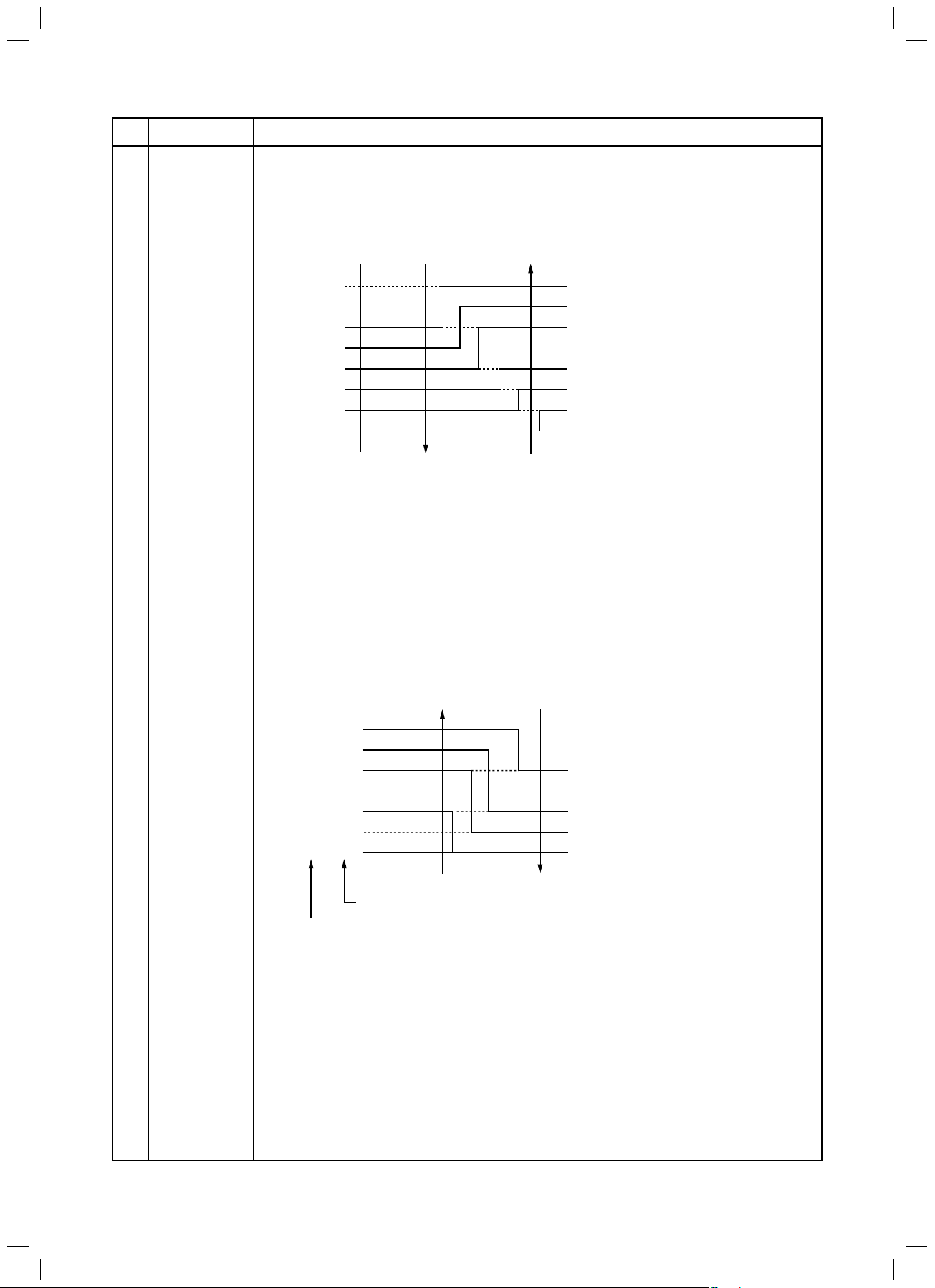
1) Based on the difference between Ta and Ts, the operation capacity is determined by the outdoor unit.
Ta
(°C)
+2
+1 Ts
Ts –1
–1 –2
COOL HEAT
SD
SB
S9
S7
S5
S3
S0
Ta
(°C)
+1
S3
S5
S7
S9
SB
SD
SF
S0
Remarks
Shift of suction
temperature in heating
operation
Except while sensor of
the remote controller is
controlled
Ts: Setup temp.
Ta: Room temp.
5
Automatic
cooling/heating
control
∗ For SHRM only
1) The judgment of selecting COOL/HEAT is carried out as
shown below. When +1.5 exceeds against Tsh
10 minutes OFF, heating operation (Thermo. OFF)
exchanges to cooling operation.
Description in the parentheses shows an example of
cooling ON/OFF.
Ta
+1.5
Tsc
Tsh
-1.5
Cooling
(Cooling ON)
(Cooling OFF)
Heating
(°C)
or
When –1.5 lowers against Tsc 10 minutes and after
thermo. OFF, cooling operation (Thermo. OFF)
exchanges to heating operation.
2) For the automatic capacity control after judgment of
cooling/heating, see Item 4.
3) For temperature correction of room temp. control in
automatic heating, see Item 3.
∗ For SHRM only
Tsc: Setup temp. in
cooling operation
Tsh: Setup temp. in
heating operation +
temp. correction of
room temp. control
– 22 –
SVM-13085.indb 22SVM-13085.indb 22 12/24/13 10:56 AM12/24/13 10:56 AM
FILE NO. SVM-13085
No.
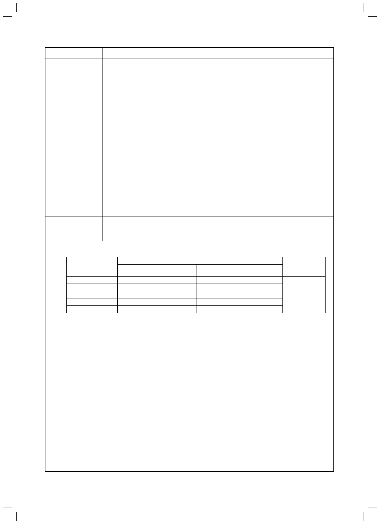
6
Item
Air speed
selection
Outline of specifications
1) Operation with (HH), (H), (L) or [AUTO] mode is carried
out by the command from the remote controller.
2) When the air speed mode [AUTO] is selected, the air
speed varies by the difference between Ta and Ts.
<COOL>
Ta ( ° C)
+3.0
+2.5
+2.0
+1.5
+1.0
+0.5
Tsc
–0.5
HH
<HH>
H+ <HH>
H <HH>
L+ <H+>
L <H>
L <H>
L <L+>
< > : Indicate automatic cooling.
A
B
C
D
E
F
G
s Controlling operation in case when thermo of remote
controller works is same as a case when thermo of
the body works.
s If the air speed has been changed once, it is not
changed for 3 minutes. However when the air volume
is exchanged, the air speed changes.
s When cooling operation has started, select a down-
ward slope for the air speed, that is, the high position.
s If the temperature is just on the difference boundary,
the air speed does not change.
Remarks
HH > H+ > H > L+ > L > UL
Code No. 32
0000: Body thermo. (Main unit)
0001: Remote controller
thermo.
<HEAT>
Ta (°C)
(–0.5) –1.0
(0) Tsh
(+0.5) +1.0
(+1.0) +2.0
(+1.5) +3.0
(+2.0) +4.0
L <L+>
L+ <H>
H <H+>
H+
<HH>
HH
<HH>
< > : Indicate automatic heating.
Body thermostat works.
Remote controller thermostat works.
E
D
C
B
A
Value in the parentheses indicates one when thermostat
of the remote controller works.
Value without parentheses indicates one when thermostat of the body works.
s If the air speed has been changed once, it is not
changed for 1 minute. However when the air speed
exchanged, the air speed changes.
s When heating operation has started, select an upward
slope for the air speed, that is, the high position.
s If the temperature is just on the difference boundary,
the air speed does not change.
– 23 –
SVM-13085.indb 23SVM-13085.indb 23 12/24/13 10:56 AM12/24/13 10:56 AM
FILE NO. SVM-13085
No.
6
Air speed selection
(Continued):
Item
Outline of specifications
Remarks
Selection of high ceiling
type CODE No. :
[5d] or selection of high
ceiling on P.C. board SW501
CODE No.
[5d]
SW501 (1)/(2) OFF/OFF ON/OFF OFF/ON
Tap COOL HEAT COOL HEAT COOL HEAT
F1 HH HH
F2 HH HH
F3 H+ H+, H H+, H
F4 H+
F5 HH H
F6 HH H L+ L+
F7 H+ H+ L L
F8 H L+
F9 H L+ L
FA L+ L
FB L+ L
FC L
FD LL LL LL
Standard Type 1 Type 3
0000 0001 0003
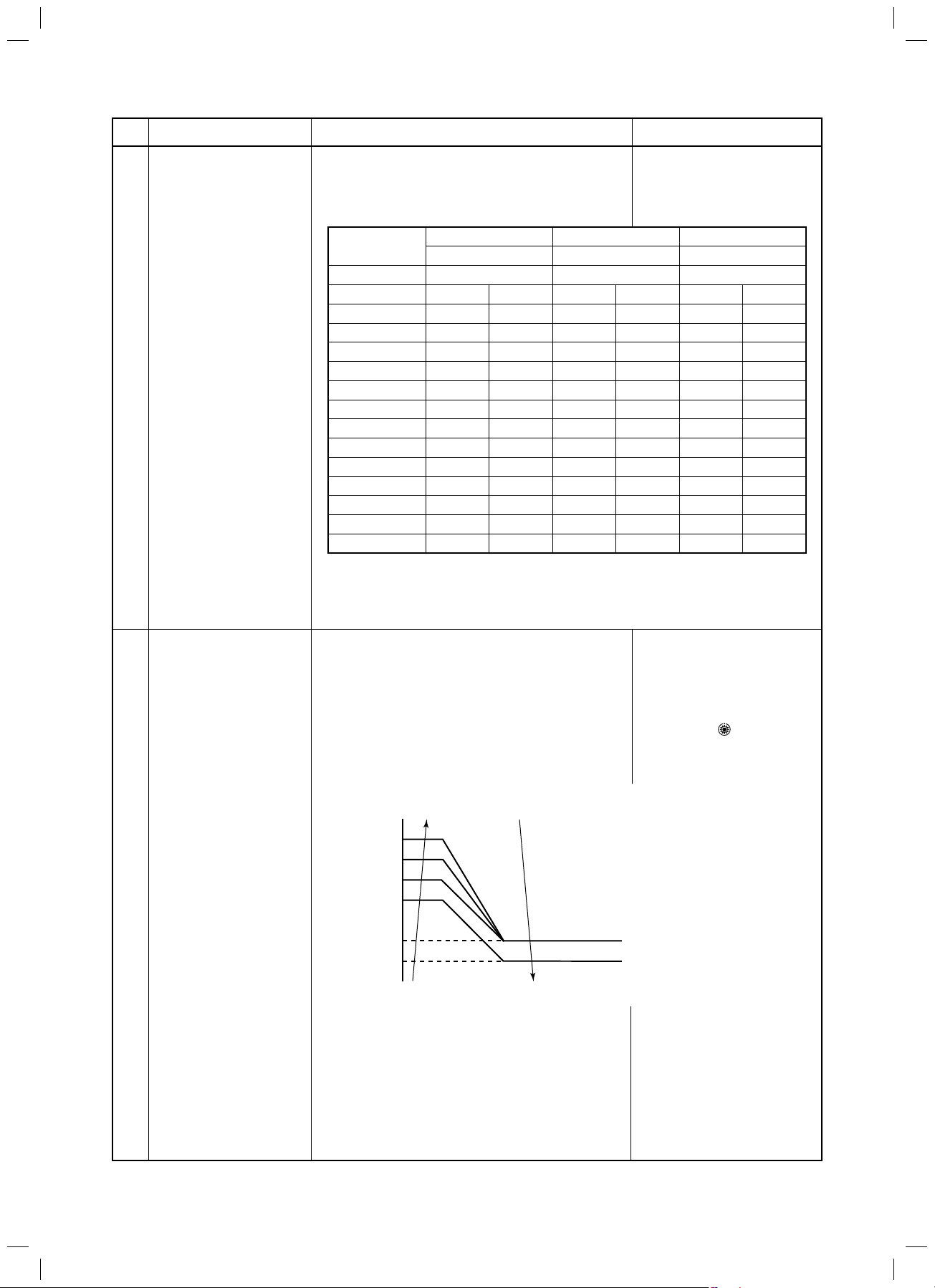
7 Prevention of cold air
discharge
3) In heating operation, the mode changes to [LL] if thermostat is turned off.
1. In heating operation, the higher temperature of
TC2 sensor and TCJ sensor is compared with
temperature of TC1 sensor and then the lower
temperature is used to set the upper limit of the
fan tap.
s When B zone has continued for 6 minutes,
TCJ: Temperature of indoor
heat exchanger sensor
s In D and E zones, priority
is given to remote controller air speed setup.
n A zone “ ” is displayed.
s I
the operation shifts to C zone.
s In defrost time, the control point is set to
+6°C.
(°C)
32
30
28
26
20
16
D
C
A zone: OFF
B zone:
Over 26°C, below 28°C, ULTRA LOW (LL)
C zone:
E
Over 28°C, below 30°C, LOW (L)
D zone:
Over 30°C, below 32°C, MED (H)
E zone: HIGH (HH)
B
A
– 24 –
SVM-13085.indb 24SVM-13085.indb 24 12/24/13 10:56 AM12/24/13 10:56 AM

FILE NO. SVM-13085
No.
8
Freeze prevention
control (Low temp.
release)
Item
Outline of specifications
1. In all cooling operation, the air conditioner operates
as described below based upon temp. detected by
TC1, TC2 and TCJ sensors.
s When “J” zone is detected for 5 minutes, the
thermostat is forcedly off.
s In “K” zone, the timer count is interrupted, and held.
s When “
I ” zone is detected, the timer is cleared
and the operation returns to the normal operation.
s When becoming thermo. OFF continuing J zone,
operation of the indoor fan in LOW mode
continues until it reaches the “
I ” zone.
It is reset when the following conditions are satisfied.
Reset conditions
1) TC1 Ӎ 12°C and TC2 Ӎ 12°C and TCJ Ӎ 12°C
2) 20 minutes passed after stop.
(°C)
P1
Q1
K
J
a
P1
Q1
TC1
10°C (5°C)
0°C
TC2, TCJ
–10°C
–14°C
2. In all cooling operation, the air conditioner operates
as described below based upon temp. detected by
TC2 and TCJ sensors.
s When “M” zone is detected for 45 minutes, the
thermostat is forcedly off.
s In “N” zone, the timer count is interrupted and held.
s When shifting to “M” zone again, the timer count
restarts and continues.
s If “L” zone is detected, the timer is cleared and the
operation returns to normal operation.
Reset conditions
1) TC1 Ӎ 12°C and TC2 Ӎ 12°C and TCJ Ӎ 12°C
2) 20 minutes passed after stop.
Remarks
TC1: Temperature of indoor
heat exchanger sensor
( ) value:
When the power supply is
turned on, the Forced
thermo becomes OFF if the
temperature is less than this
indicated temperature.
9
Recovery control
for cooling oil
(Refrigerant)
(°C)
P2
Q2
L
N
M
P2
Q2
TC2, TCJ
5°C
–2°C
The indoor unit which is under STOP/Thermo. OFF
status or which operates in [FAN] mode performs the
following controls when it received the cooling oil
(Refrigerant) recovery signal from the outdoor unit.
1) Opens PMV of the indoor unit with a constant
opening degree.
2) Operates the indoor fan and drain pump for approx.
1 minute during recovery control and after finish of
control.
The direction of the louver becomes horizontal
direction.
– 25 –
s Recovery operation is
usually performed every
2 hours.
SVM-13085.indb 25SVM-13085.indb 25 12/24/13 10:56 AM12/24/13 10:56 AM
FILE NO. SVM-13085
No.
10
Recovery control
for heating
refrigerant (Oil)
Compensation
11
control for short
intermittent
operation
Drain pump
12
control
䈜Option
Item
Outline of specifications
The indoor unit which is under STOP/Thermo. OFF
status or which operates in [FAN] mode performs the
following controls when it received the heating
refrigerant (Oil) recovery signal from the outdoor unit.
1) Opens PMV of the indoor unit with a constant
opening degree.
2) Detects temperature of TC2 and then closes PMV.
3) Counts No. of recovery controls and operates the
indoor fan and the drain pump for approx. 1 minute
after finish of recovery control until the control
count reaches the specified count.
The direction of the louver becomes horizontal
direction.
1) For 5 minutes after start of operation, the operation is forcedly continued even if the unit enters in
thermo. OFF condition.
2) However the thermostat is OFF giving prior to
COOL/HEAT selection, READY
for operation
and protective control.
1) Drain pump operates while in cooling operation.
(including DRY operation)
2) During operation of the drain pump, if the float
switch operates, the drain pump continuously
operates and a check code is illuminated.
3) During stop status of the drain pump, if the float
switch operates, the thermostat is forcedly off and
this control operates the drain pump. After
continuous operation of the float switch for approx.
5 minutes, this control stops the operation and a
check code is issued.
Remarks
s The indoor unit which is
under thermo. OFF (COOL)
status or which operates in
[FAN] mode stops the indoor
fan and displays [READY
s Recovery operation is usually
performed every 1 hour.
Attached Drain pumpkit
(TCB-DP31CE)
Check Code [P10]
].
Elimination of
13
retained heat
HA control
14
Display of filter
15
sign [
(Not provided to
the wireless type)
1) When the unit stopped from [HEAT] operation, the
indoor fan operates with [L] for approx. 30 seconds.
1) ON/OFF operation is available by input of HA
signal from the remote site when connected to
remote controller or the remote ON/OFF interface.
2) HA control outputs ON/OFF status to HA terminal.
3) The I/O specifications of HA conform to JEMA
standard.
When using HA terminal
(CN61) for the remote ON/
OFF, a connector sold separately is necessary.
In case of group operation, use
the connector to connect HA
terminal to either header or
follower indoor unit.
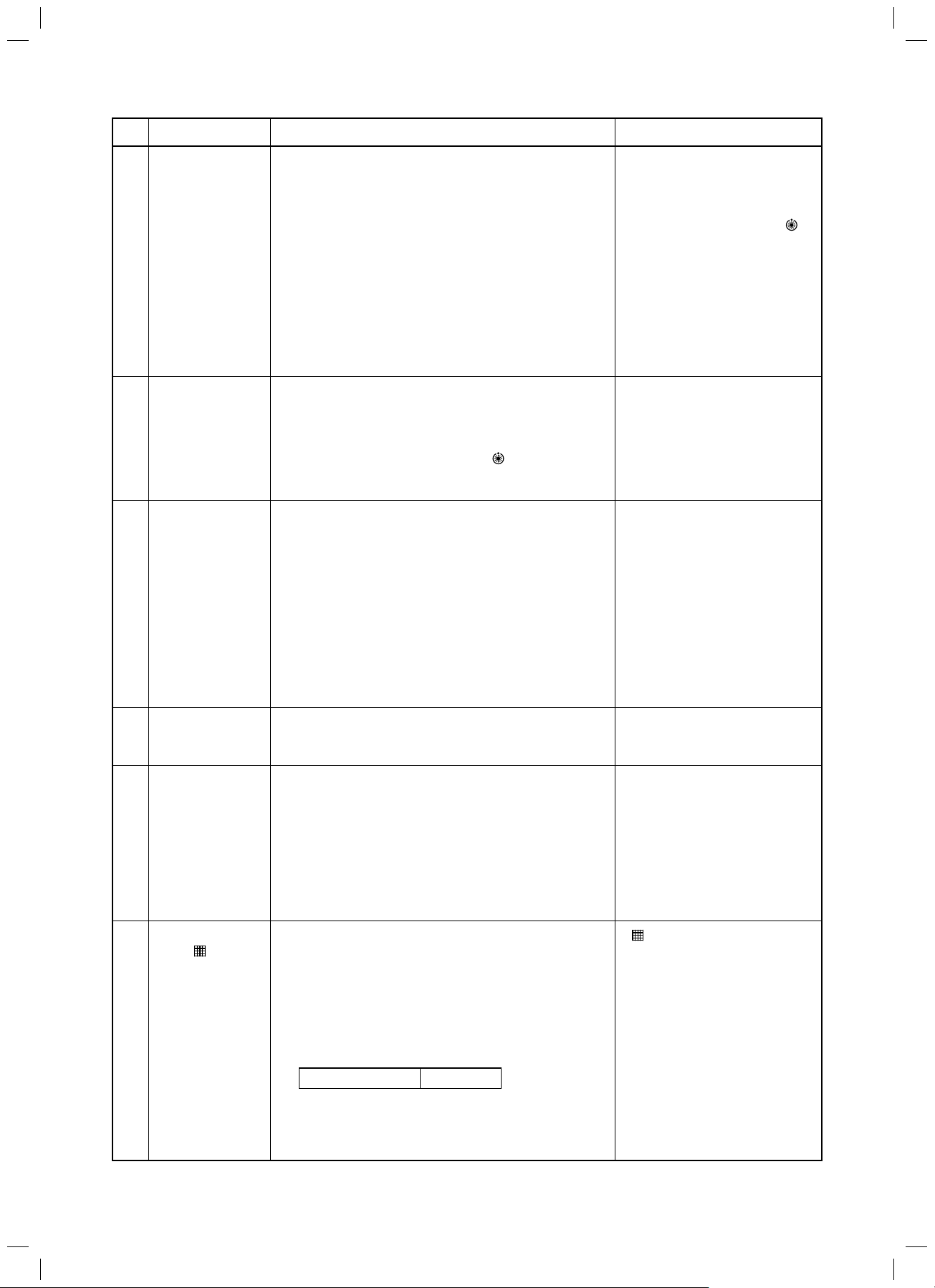
1) The filter sign is displayed with LCD by sending
]
the filter-reset signal to the remote controller when
[ FILTER] goes on.
the specified time (2500H) elapsed as a result of
integration of the operation time of the indoor fan.
2) The integrated timer is cleared when the filter-reset
signal is received from the remote controller.
In this time, if the specified time elapsed, the
counted time is reset and the LC display is deleted.
Filter time 2500H
– 26 –
SVM-13085.indb 26SVM-13085.indb 26 12/24/13 10:56 AM12/24/13 10:56 AM
FILE NO. SVM-13085
No.
16
Display of
[READY]
[HEAT READY]
Item
Outline of specifications
< READY> Displayed on the remote controller
1) When the following check codes are indicated
s Open phase of power supply wiring [P05] was detected.
s There is an indoor unit that detected the indoor overflow
[P10].
s There is an indoor unit that detected the interlock alarm
[L30].
2) During forced thermo. OFF
s [COOL/DRY] operation is unavailable because the other
indoor unit operates with [HEAT] mode.
s [HEAT] operation is unavailable because COOL priority
(SW11-bit1 of the Outdoor I/F P. C. board is ON) is set and
the other indoor unit operates with [COOL/DRY] mode.
3) When the above indoor units that cannot operate stay in
thermo. OFF status.
4) When the indoor fan stops because the system performs
[Recovery operation for heating refrigerant (Oil)].
<HEAT READY> Displayed on the remote controller
When the indoor fan stops in order to prevent discharge of cool
air when heating operation started or during heating operation.
(including the defrost operation during thermo. OFF)
Remarks
s < READY> display
No display for wireless
type remote controller
s <HEAT READY>
display
Selection of
17
central control
mode
1) Selection of the contents that can be operated by the remote controller at the indoor
unit side is possible according to setting at the central controller side.
2) Setting contents
s In case of TCC-LINK central control
Operation from
TCC-LINK
central control
Individual
[Central 1]
[Central 2]
[Central 3]
[Central 4]
({: Operation possible ×: Operation impossible)
Operation on RBC-AMT32E
ON/OFF Operation Timer Temp. Air speed Air direction
setting selection setting setting setting setting
{{{{ { {
×
{
×
××××
{
{
×
×
{
{{ { {
{{ {
{{
×
{{
On
RBC-AMT32E
[Central control]
display
– 27 –
SVM-13085.indb 27SVM-13085.indb 27 12/24/13 10:56 AM12/24/13 10:56 AM
FILE NO. SVM-13085
No.
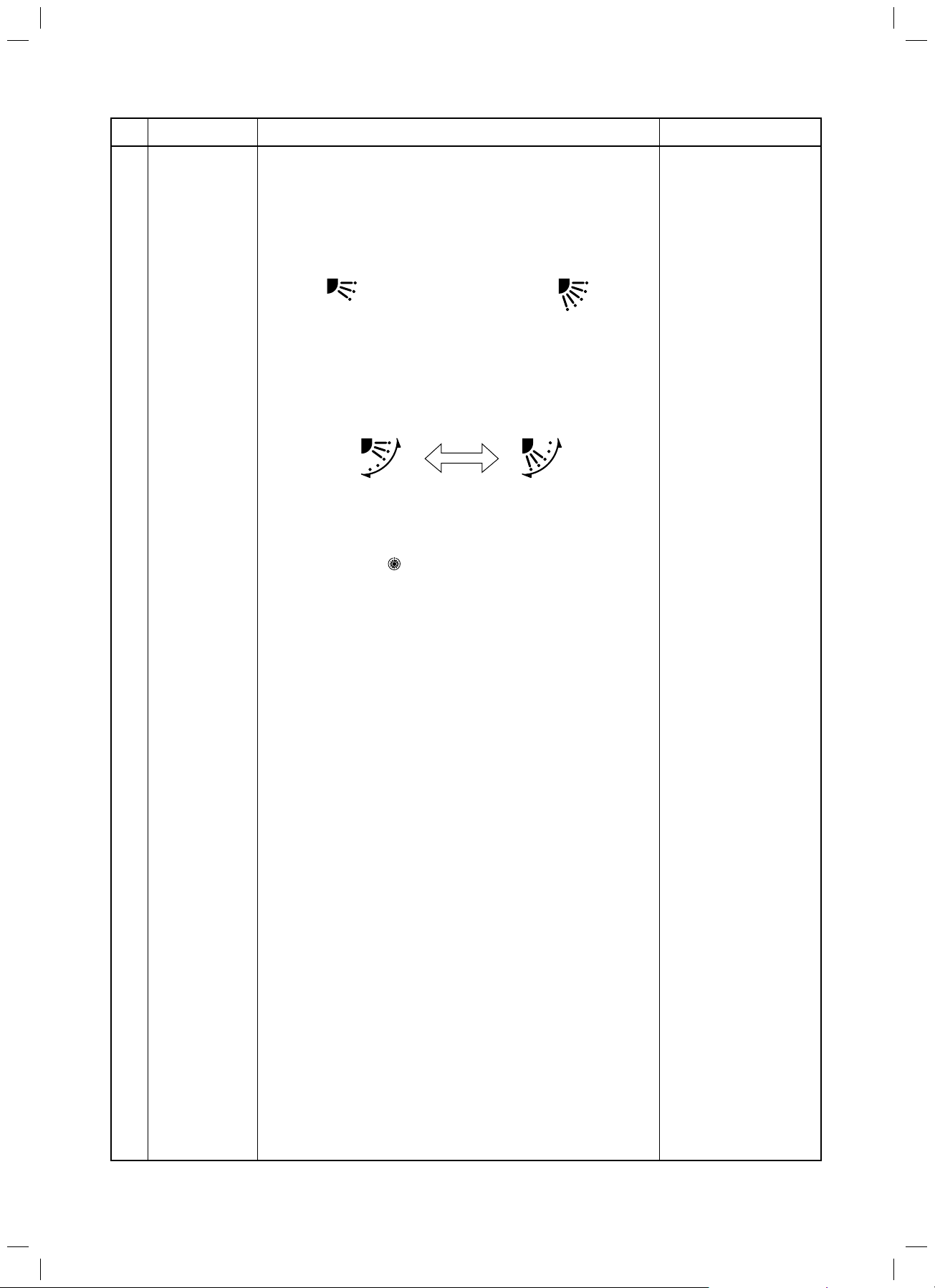
18
Item
Louver control:
Outline of specifications
1) Louver position setup
s When the louver position is changed, the position moves
necessarily to downward discharge position once to return to
the set position.
s The louver position can be set up in the following operation
range.
In cooling/dry operation In heating/fan operation
s In group operation, the louver positions can be set up
collectively or individually.
In case of refrigerant recovery control, the louver position
becomes horizontal.
2) Swing setup
s [SWING] is displayed and the following display is repeated.
In all operations
(Repeats)
s In group operation, the louver positions can be set up
collectively or individually.
3) When the unit stopped or the warning was output, the louver is
automatically set to full closed position.
4) When PRE-HEAT
(Heating operation started or defrost operation is performed),
heating thermo is off, the louver is automatically set to horizontal
discharge position.
(Heating ready) is displayed
Remarks
– 28 –
SVM-13085.indb 28SVM-13085.indb 28 12/24/13 10:56 AM12/24/13 10:56 AM
FILE NO. SVM-13085
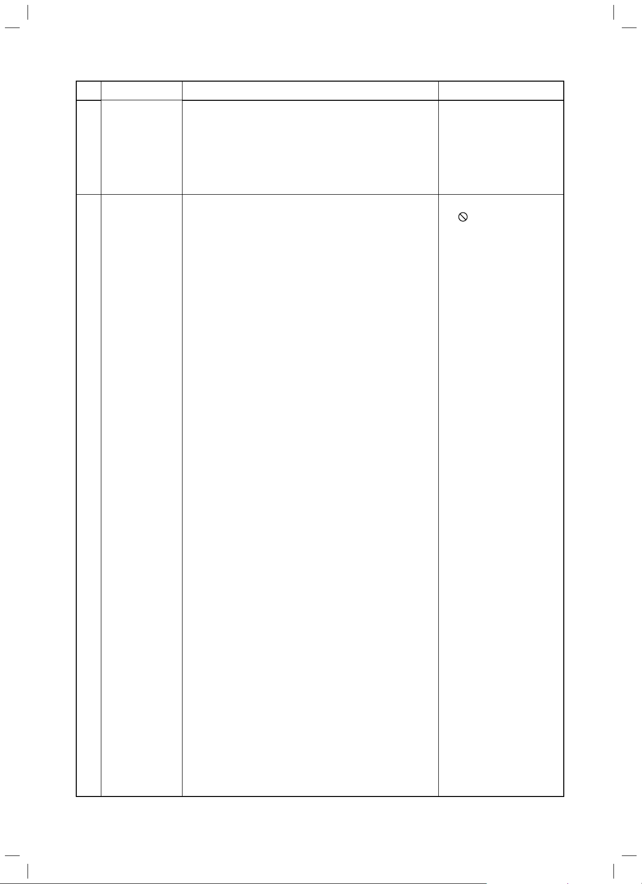
No.
Item
Outline of specifications Remarks
19 DC motor 1) DC motor operates according to the command from
the indoor controller.
(Note) If the fan rotates by entry of outside air, etc while
the air conditioner stopped, the indoor unit may
operate as the fan motor stops.
(Note) If the fan lock was detected, the operation of the
indoor unit stops and the error is displayed.
20 Save operation 1) The function [Save operation] is not provided to the
Super Modular Multi series models.
Check code [P12]
s If pushing [SAVE] button
” on the remote
“
controller, “No function”
is displayed.
– 29 –
SVM-13085.indb 29SVM-13085.indb 29 12/24/13 10:56 AM12/24/13 10:56 AM
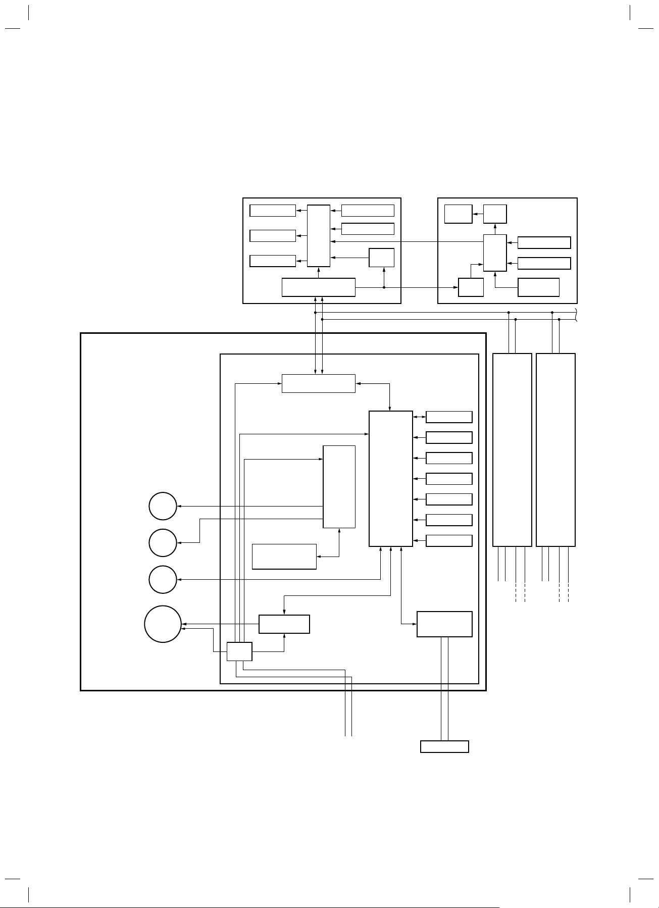
6. CONFIGURATION OF CONTROL CIRCUIT
6-1. Indoor Unit
6-1-1. Indoor Controoler Block Diagram
1. Connection of wired remote controller
Wired (Simple) header remote controller
(Up to 2 units) Schedule timer
FILE NO. SVM-13085
Indoor unit
#1 (Header)
PMV
Display LCD
Display LED
EEPROM
Remote controller
communication circuit
Indoor control P.C. board
(MCC-1643)
DC20V
DC5V
DC12V
Remote controller
communication circuit
CPU
AB
Driver
Function setup
Key switch
DC5V
Powe r
circuit
MCU
CN2
CN1
1
*
EEPROM
TA sensor
TC1 sensor
TC2 sensor
TCJ sensor
Float input
Display
LCD
DC5V
Powe r
circuit
LCD
driver
Function setup
CPU
Key switch
Secondary
battery
#2
(Follower)#3(Follower)
AB
Same
as left
AB
Same
as left
Powe r
circuit
Outside output
Start/Alarm/Ready
Thermostat ON
COOL/HEAT/FAN
Fan motor
control circuit
Louver
motor
Drain
pump
䈜Option
Indoor
fan motor
DC
280V
Max. 8 units are connectable.
*1 The schedule timer cannot be connected to the simple wired
remote controller.
L N U1 U2
Power supply
1Ø220-240V, 50Hz
1Ø220V, 60Hz
HA
BUS
communication
circuit
Indoor/Outdoor
communication
U1 U2
Outdoor unit
L
Powe r
supply
U1 U2
N
Outdoor
unit
L
Powe r
supply
U1 U2
N
Outdoor
unit
– 30 –
SVM-13085.indb 30SVM-13085.indb 30 12/24/13 10:56 AM12/24/13 10:56 AM
 Loading...