

Page 1

FILE NO. 400-200603GR
DOCUMENT CREATED IN JAPAN, JUNE, 2006
SERVICE MANUAL
Series
DIGITAL AUDIO PLAYER
MES60V, MES30V
(US/CA)
The above models are classified as green products (*1).
This Service Manual describes replacement parts for the green products. When repairing these green
product(s), use the part(s) described in this manual and lead-free solder (*2).
For (*1) and (*2), see the next page.
Jun., 2006
Page 2

(*1) GREEN PRODUCT PROCUREMENT
IN-WARRANTY SERVICE
In-Warranty service for the MES60V and MES30V Digital Audio Player
is fulfilled via product exchange.
Contact Toshiba Customer Solutions for instructions. 1-866-583-7353.
The EC is actively promoting the WEEE & RoHS Directives that define standards for recycling
and reuse of Waste Electrical and Electronic Equipment and for the Restriction of the use of
certain Hazardous Substances. From July 1, 2006, the RoHS Directive will prohibit any marketing
of new products containing lead.
Increasing attention is given to issues related to the global environmental. Toshiba Corporation
recognizes environmental protection as a key management tasks, and is doing its utmost to
enhance and improve the quality and scope of its environmental activities. In line with this,
Toshiba proactively promotes Green Procurement, and seeks to purchase and use products,
parts and materials that have low environmental impacts.
Green procurement of parts is not only confined to manufacture. The same green parts used in
manufacture must also be used as replacement parts.
(*2) LEAD-FREE SOLDER
This product is manufactured using lead-free solder as a part of a movement within the CE
industry at large to be environmentally responsible. Lead-free solder must be used in the servicing
and repair of this product.
WARNING
This product is manufactured using lead free solder.
DO NOT USE LEAD BASED SOLDER TO REPAIR THIS PRODUCT !
The melting temperature of lead-free solder is higher than that of leaded solder by 86°F to 104°F
(30°C to 40°C). Use of a soldering iron designed for lead-based solders to repair product made
with lead-free solder may result in damage to the component and or PCB being soldered. Great
care should be made to ensure high-quality soldering when servicing this product –especially
when soldering large components, through-hole pins, and on PCBs – as the level of heat required
to melt lead-free solder is high.
Page 3

Precautions
Safety Precautions for Service
This section provides critical information for safety. Be sure to observe the content.
Meaning of each indication is as follows:
Safety indications mean that death or serious injury may be caused to service personnel
DANGER
WARNING
CAUTION
* Physical damage includes damage to buildings, household goods, properties, livestock, and pets.
and/or surrounding people or users due to incorrect work by neglecting safety instructions or due to resulting defects of the product, which indicates imminence of danger.
Death or serious injury may be caused to service personnel and/or surrounding people
or users due to incorrect work by neglecting the following instructions or due to
resulting defects of the product.
Injury or physical damage* may be caused to service personnel and/or surrounding
people or users due to incorrect work by neglecting the following instructions or due to
resulting defects of the product.
WARNING
• Unplug the power cable before starting work (for example, disassembly) that does not need power
supply.
Otherwise, it may cause electric shock.
• Use an insulation transformer and/or wear protective gloves when power is ON, and unplug the power
cable when replacing parts to avoid electric shock.
• Use specified spare parts of the product for replacement.
Since some parts have safety characteristics (fire resistance, withstand voltage, etc.), use replacement parts
with same characteristics.
For safety-sensitive parts specified by marking in circuit diagrams or parts lists, use specified parts.
• After repair work is completed, properly reassemble disassembled parts and securely reconnect cables
as they were.
For safety reasons, some insulating materials such as tubes and tapes are used, and some parts are mounted
with a gap from the board surface. Furthermore, internal wiring is kept away from heating parts or highvoltage parts by using clampers or by other means. When reassembling/reconnecting these parts, put them as
they were.
Do not catch the internal cables by the cabinet or cover. Improper assembling or cable connection may cause
electric leak or fire, which may lead to an accident on the user side.
• After repair work is completed, unplug the power cable, and measure the insulation resistance between
the external metal portion and plug blade with a 500V megger. The resistance shall be 1M ohms or
more.
If the resistance is lower than 1M ohms, inspect and rectify the product.
• Do not alter the product.
Alteration of the product may cause malfunction or failures, which may lead to an accident such as electric
leak or fire on the user side.
• Advise users to keep children away from the on-site work area.
Children in the work area may be injured by tools, disassembled product or parts.
Page 4

Precautions for Removing the Built-in Battery
Do not attempt to drive a nail into the built-in battery, nor strike it with a hammer, step
DANGER
DANGER
DANGER
DANGER
DANGER
DANGER
WARNING
WARNING
on it or otherwise subject it to strong impact. The electrodes may shortcircuit, resulting
in heat generation, explosion or ignition.
Do not connect the electrodes (positive/negative terminals) of the built-in battery using
a wire or other metal object. Also avoid carrying or storing the battery together with a
necklace, hairpin or other object made of metal. The electrodes may short-circuit,
resulting in heat generation, explosion or ignition.
Do not heat, disassemble or modify the built-in battery or place it in fire or water.
Doing so may cause an explosion, ignition or heat generation, resulting in fire or
serious injury.
Do not place the built-in battery near fire or in the heat of the sun.
Doing so may result in fire, explosion or heat generation.
Do not bring the built-in battery near heating equipment. Doing so may result in fire,
explosion or heat generation.
Wrap the connector of the built-in battery with insulation tape.
Otherwise, the electrodes may short-circuit, resulting in heat generation, explosion or
ignition.
Do not place the built-in battery within the reach of small children.
Doing so may result in injury or accident.
If leaked fluid from the built-in battery should enter your eye, rinse with clean water
and seek immediate medical attention. Neglecting proper cleaning or medical treatment
may result in eye injury.
Page 5

CONTENTS
1. PRODUCT OVERVIEW ........................................................................................................................2
1.1. PRODUCT OUTLINE ....................................................................................................................................2
1.1.1. INTERNAL COMPOSITION...................................................................................................................2
1.1.2. ACCESSORIES .....................................................................................................................................3
1.1.3. PLACE FOR STORING THE FIRMWARE.............................................................................................3
1.1.4. ABOUT CONTENT PROTECTION........................................................................................................3
1.1.5. HOW MUSIC/VIDEO IS PLAYED BACK ...............................................................................................4
1.1.6. TRANSFER OF CONTENT FROM THE PC..........................................................................................4
2. BLOCK DIAGRAM ............................................................................................................................... 5
2.1. LOGIC CIRCUIT BLOCK DIAGRAM.............................................................................................................5
2.2. POWER CIRCUIT BLOCK DIAGRAM...........................................................................................................6
3. CAUTIONS ON REPAIR .......................................................................................................................7
3.1. TELL THE OWNER THAT THE CONTENTS ON THE HDD MAY BE ERASED. ..........................................7
3.2. REMOVE THE AC ADAPTOR AND SET THE BATTERY SWITCH TO OFF.................................................7
3.3. WHEN REPLACING THE HDD.....................................................................................................................8
3.3.1. PROTECT THE HDD FROM IMPACT....................................................................................................8
3.3.2. HOLDING THE HDD..............................................................................................................................8
3.3.3. PROCESS AT HDD REPLACEMENT....................................................................................................9
3.4. WHEN REPLACING THE MAIN BOARD....................................................................................................12
3.4.1. UPDATING THE FIRMWARE. .............................................................................................................12
3.5. WHEN REPLACING THE LCD AND LCD BACKLIGHT UNIT ....................................................................16
3.5.1. INCORPORATING THEM INTO THE LCD FRAME ............................................................................16
4. TROUBLESHOOTING........................................................................................................................17
4.1. ANTICIPATED DEFECTS............................................................................................................................17
4.2. DEFECT ANALYSIS PROCEDURE AS A MAINTENANCE SERVICE ........................................................18
4.2.1. THE UNIT WILL NOT TURN ON. ........................................................................................................18
4.2.2. NO SOUND COMES OUT. ..................................................................................................................20
4.2.3. FM CANNOT BE RECEIVED...............................................................................................................20
4.2.4. THE SOUND IS ODD. .........................................................................................................................21
4.2.5. THE LCD DISPLAY IS ODD. ...............................................................................................................21
4.2.6. THE BUTTONS OF UNIT DO NOT WORK. ........................................................................................21
4.2.7. THE REMOTE CONTROLLER DOES NOT WORK. ...........................................................................21
4.2.8. THE USB CONNECTION FAILS. ........................................................................................................21
4.2.9. THE BATTERY CANNOT BE RECHARGED.
(WHEN BATTERY-POWERED, THE UNIT PLAYS BACK ONLY FOR A SHORT TIME.)....................22
4.2.10. HDD IS NOT RECOGNIZED. ..............................................................................................................23
5. PROCEDURE TO CONFIRM THE UNIT’S F/W VERSION................................................................ 24
6. DISASSEMBLING/REASSEMBLING PROCEDURES ......................................................................25
6.1. DISASSEMBLING PROCEDURES.............................................................................................................25
6.2. REASSEMBLING PROCEDURES..............................................................................................................30
7. EXPLODED VIEW .............................................................................................................................. 34
8. PARTS LIST........................................................................................................................................35
1
Page 6

1. Product Overview
[TOSHIBA HDD audio player gigabeat S series] is the portable audio player in which the HDD of 30GB/60GB is
built. As the built-in HDD is thick, the MES60 is thicker.
Main differences from the previous model (gigabeat X series) are as follows.
• By adopting the push-type button, the operability is enhanced.
• PMC (Portable Media Center) is adopted.
1.1. Product Outline
1.1.1.
Internal Composition
The gigabeat S series consists of the following main components.
• Main board
A part of firmware is stored in the flash ROM on the main board.
• HDD
The HDD is partitioned into two partitions. One is for data and the other is for system.
The firmware is stored in the system partition.
Contents such as music data are stored in the data partition.
Data other than music data such as Word files can be stored in the external HDD.
(But, files cannot be directly opened.)
• TFT color liquid crystal display
• White LED backlight
• Battery
• Switches
13 pieces PMC compliant push button (7 pieces on the front, 6 pieces at sides)
• Cabinet parts
The HDD is covered with special rubber and held in the air. This keeps it resistant to impact and
vibration.
2
Page 7

1.1.2. Accessories
The product is furnished with main accessories as follows.
• AC adaptor
• Power cord (which varies with destinations.)
• USB cable
• USB conversion cable
• Wired remote controller (Option)
• Headphones
• Software CD-ROM
Owner’s Manual
1.1.3. Place for storing the firmware
The firmware is stored in the flash ROM on the main board and on the HDD. The firmware is stored in the
system partition on the HDD. Even if a PC is connected, the system partition cannot be seen on the Explorer.
1.1.4. About Content Protection
Using the Windows Media DRM10, the contents are protected.
Using the Windows standard application Windows Media Player 10, transfer (copy) the music data
(WMA/MP3/WAV format)/video data (WMV) stored in a PC to the HDD so that the transferred content can
be played back. Transferring the data via USB is also possible.
When the content, which is once transferred to a PC by the Explorer, is transferred to other gigabeat S series,
unless the content is protected by the Windows Media DRM, the content can be played back. But, when the
content protected by the Windows Media DRM is transferred to other gigabeat S series, unless the license of
the content to be transferred is acquired, the content cannot be played back.
3
Page 8

1.1.5. How music/video is played back
This section explains how the unit plays back the content (compressed music data (WMA/MP3, PCM music
data (WAV) and video data (WMV)) stored on the HDD.
The CPU reads out the content data (WMA/MP3/WAV/WMV) on the HDD and stores it in the SDRAM.
The CPU accesses to the HDD every few minutes (It differs depending on the content’s bit rate.), reads out
the data, and accumulates it in the SDRAM. When the HDD is not accessed, the power of HDD is turned off
to save the power. However, as the PCM music data contains the large amount, the HDD is always powered.
The CPU restores the compressed music data in the SDRAM and converts it to PCM data.
If the data in the SDRAM is video, the CPU restores it to bit map data. The music data restored to the PCM is
sent from the SDRAM to the DAC by the CPU. In case of video data, the CPU sends the bit map data to the
LCD.)
The DAC converts the PCM music data to the analog signal, which is then outputted to headphones. The CPU
sets the volume control and equalizer levels in the DAC, which controls the volume level and equalizer levels,
using their set data.
1.1.6. Transfer of content from the PC
When the unit is connected to the PC with the USB cable, the PC recognizes the unit as a MTP device
(MultiMedia Transfer Protocol device).
When transferring the content by using the Windows Media Player on the PC, the content data is sent to the
unit via USB. Then, according to the MTP protocol, the CPU writes the received content data on the HDD.
4
Page 9

2. Block diagram
2.1. Logic circuit block diagram
5
Page 10

2.2. Power circuit block diagram
6
Page 11

3. Cautions on repair
Before repairing a product of the gigabeat S series, take the following cautions:
3.1. Tell the owner that the contents on the HDD may be erased.
Replacing or formatting the HDD will erase the content on the HDD.
Therefore, in receiving the product from the owner, ask the owner to back up his/her important data.
3.2. Remove the AC adaptor and set the BATTERY switch to OFF.
Before disassembling, ensure to remove the AC adaptor and set the BATTERY switch to “OFF”.
When the gigabeat S series is powered by the AC adaptor or the battery, even if the power switch is turned off,
the power is supplied to the LCD and almost all ICs. Therefore, before repairing, the AC adaptor or the battery
must be removed.
By setting the BATTERY switch to “OFF”, the power supply from the battery is stopped and the unit becomes
in the same state as when the battery is removed.
7
Page 12

3.3. When replacing the HDD
3.3.1. Protect the HDD from impact.
Note that the HDD is vulnerable to impact. Merely falling the HDD from a vertical position would give an
impact exceeding the specifications.
3.3.2. Holding the HDD
When holding the HDD, hold it at the following position:
Do not hold it at the following position:
8
Page 13

3.3.3. Process at HDD replacement
When replaced to the un-formatted HDD, restore the HDD in the factory setting state by transferring the
firmware and the supplied data to the HDD in the procedure below.
[HDD formatting]
1) Set the BATTERY switch to “OFF”.
2) Connect the AC adaptor and start up the unit.
3) Format automatically the HDD and display the menu below on the LCD. Wait until the menu appears.
Menu of waiting for the PC connection
Fig.
[T&D Transfer]
4) Start up [Transfer Program (Ottoman.exe) on the PC and select the scenario file (*.ini) in which files
to be transferred are described.
(Material No.:
on the destination. The relationship between destination and folder is shown on the table below.
Table Destination and Folder
Destination Folder name Scenario file name
Japan OTTOMAN_T&D_FW_JP OTTOMAN_T&D_FW_JP.ini
U.S.A. OTTOMAN_T&D_FW_US OTTOMAN_T&D_FW_US.ini
Start up Ottoman.exe and select the scenario file. Then, the menu below appears.
360058245). Names for the destination-wise stored folder and file are different depending
Ottoman.exe and the scenario file are provided on the CD-ROM
9
Page 14
(A)
(B)
Fig. Menu display on the PC (T&D Transfer)
Check two points of (A) and (B) on the above menu. These are different for every destination ((A) is
same.) The display for every destination is as shown below.
Table Difference on the display by destination (Differences are underlined.)
Destination (A) (B)
Japan version 0.9.9.10 T&D TRANS PROG(JP
U.S.A. version 0.9.9.10 T&D TRANS PROG(US
) Ver.6423A
) Ver.6423A
5) Wait for a while. Then, “OK” appears on the PC.
6) Remove the USB cable. At this moment, be careful not to touch the POWER button.
By removing the USB cable, “OK” on the PC disappears.
7) The unit is automatically started up.
[Transfer of FW for factory setting]
8) Transfer the FW for factory setting in the same manner as in step 4). Terminate Ottoman.exe once.
And start up newly the [Transfer Program (Ottomam.exe)] on the PC and select the scenario file (*.ini) in
which files to be transferred are described.
Ottoman.exe and the scenario file are provided on the CD-ROM (Material No.: 360058245).
Names for the destination-wise stored folder and file are different depending on the destination.
The relationship between destination and folder is shown on the table below.
10
Page 15

Table Destination and Folder
Destination Folder name Scenario file name
Japan OTTOMAN_DEL_JP OTTOMAN_DEL_JP.ini
U.S.A. OTTOMAN_DEL_US OTTOMAN_DEL_US.ini
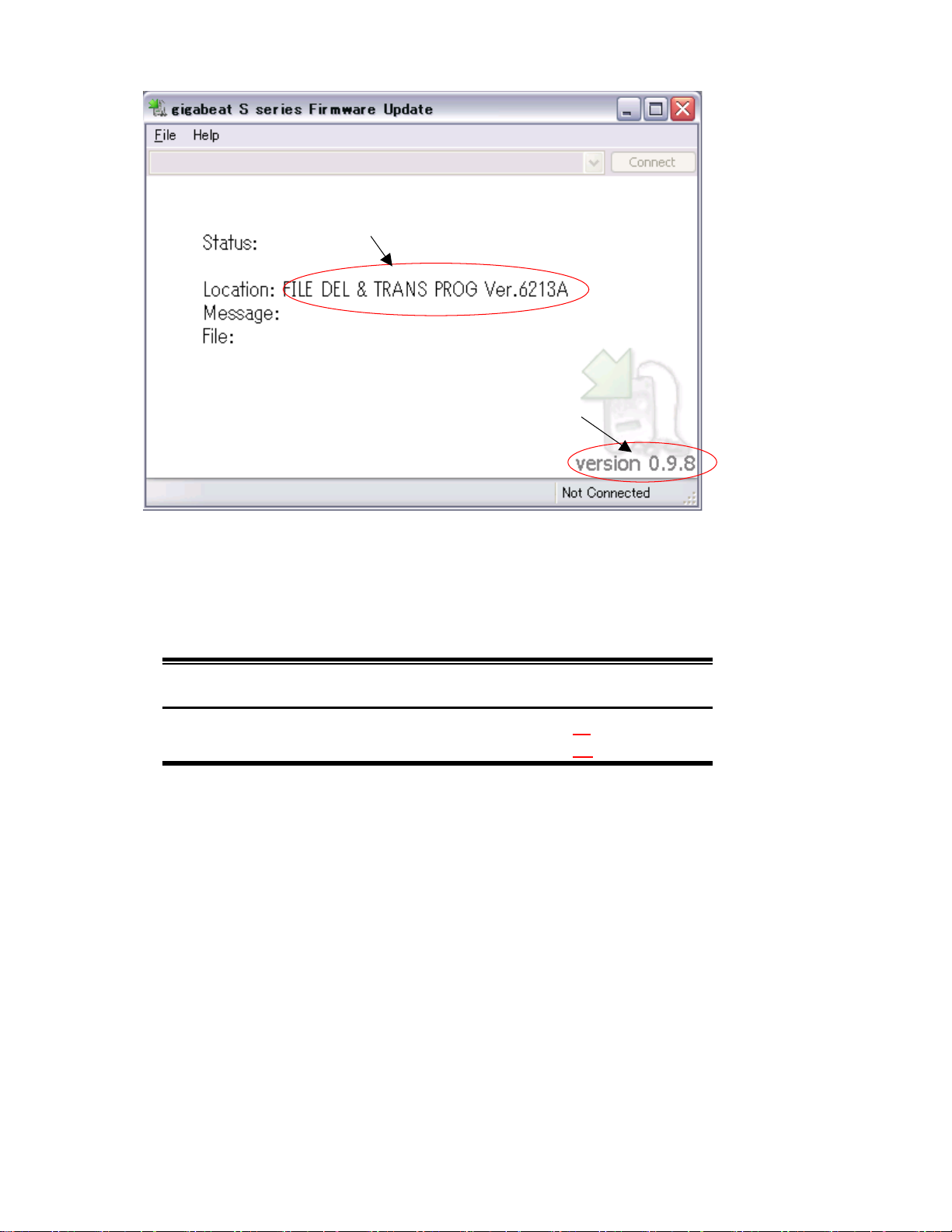
The menu display is the same as in step 4). Check two points of (A) and (B) on the menu in step 4).
These are different for every destination ((A) is same.) The display for every destination is shown below.
Table Differences of display by destination (Differences are underlined.)
Destination (A) (B)
Japan version 0.9.9.10 FILE DEL & TRANS PROG(JP
U.S.A. version 0.9.9.10 FILE DEL & TRANS PROG(US
) Ver.6423A
) Ver.6423A
9) Wait for a while. Then, “OK” appears on the PC.
10) Remove the USB cable. At this moment, be careful not to touch the POWER button. By removing the
USB cable, “OK” on the PC disappears.
11) The unit is automatically started up.
[Transfer of supplied data for factory setting]
12) Transfer the supplied data for factory setting in the same manner as in step 4). Terminate Ottoman.exe
once. Then, start up newly the [Transfer Program (Ottoman.exe)] on the PC and select the scenario file
(*.ini) in which files to be transferred are described.
Ottoman.exe and the scenario file are provided on the CD-ROM (Material No.: 360058245). Names for
the destination-wise stored folder and file are different depending on the destination. The relationship
between destination and folder is shown on the table below.
Table Destination and Folder
Destination Folder name Scenario file name
Japan OTTOMAN_SAMPLE_JP OTTOMAN_SAMPLE_JP.ini
U.S.A. OTTOMAN_SAMPLE_US OTTOMAN_SAMPLE_US.ini
The menu display is the same as in step 4). Check two points of (A) and (B) on the menu in step 4).
These are different for every destination ((A) is same.) The display for every destination is shown below.
11
Page 16

Table Differences of display by destination (Differences are underlined.)
Destination (A) (B)
Japan version 0.9.9.10 TRANS SAMPLE COMTENTS(JP
U.S.A. version 0.9.9.10 TRANS SAMPLE COMTENTS (US
) Ver.6423A
) Ver.6423A
13) Wait for a while. Then, “OK” appears on the PC.
14) Remove the USB cable. At this moment, be careful not to touch the POWER button.
By removing the USB cable, “OK” on the PC disappears.
15) Hold down the Power key to suspend (Power OFF).
16) Plug out the AC adaptor.
3.4. When replacing the main board
3.4.1. Updating the firmware.
After replacing the main board, update the firmware in the procedure below.
As explained in “1.1.3 Location to store the firmware”, the firmware is stored in both the flash ROM on the
main board and on the HDD. Unless the versions of firmware at two locations are matched, the malfunction
will occur. Therefore, whenever the main board is replaced, update the firmware in the procedure below to
match the versions at two locations.
For the procedure when replacing the HDD, see “3.3 When replacing the HDD”.
[HDD formatting]
1) Set the BATTERY switch to “OFF”.
2) Connect the AC adaptor and start up the unit.
3) Format automatically the HDD and display the menu below on the LCD. Wait until the menu appears.
Fig. Menu of waiting for the PC connection
12
Page 17

(A)
(B)
[T&D Transfer]
4) Start up the [Transfer Program (Ottoman.exe)] on the PC and select the scenario file (*.ini) in which
files to be transferred are described.
Ottoman.exe and the scenario file are provided on the CD-ROM (Material No.:
360058245). Names for
the destination-wise stored folder and file are different depending on the destination. The relationship
between destination and folder is shown on the table below.
Table Destination and Folder
Destination Folder name Scenario file name
Japan OTTOMAN_T&D_FW_JP OTTOMAN_T&D_FW_JP.ini
U.S.A. OTTOMAN_T&D_FW_US OTTOMAN_T&D_FW_US.ini
Start up the Ottoman.exe and select the scenario file. Then, the menu below appears.
.
Fig. Menu display on the PC (T&D Transfer)
Check two points of (A) and (B) on the above menu. These are different depending on the destination
((A) is same.) The display for every destination is as follows.
Table Differences of display by destination (Differences are underlined.)
Destination (A) (B)
Japan version 0.9.9.10 T&D TRANS PROG(JP
U.S.A. version 0.9.9.10 T&D TRANS PROG(US
) Ver.6423A
) Ver.6423A
13
Page 18

5) Wait for a while. Then, “OK” appears on the PC.
6) Remove the USB cable. At this moment, be careful not to touch the POWER button.
By removing the USB cable, “OK” on the PC disappears.
7) The unit is automatically started up.
[T&D Execution]
8) Execute T&D. For procedures, refer to the function test of unit’s board.
<Function test of unit’s board>
[Preparation] (Equipment required)
Wired remote controller
AC adaptor and AC cord
AV cable (Only for model equipped with TV output function)
Display with composite input (Only for model equipped with TV output function)
[Inspection]
a) Connect the AC adaptor to the unit. The OS stored on the HDD starts up.
b) Using the buttons on the front of unit, select T&D from the menu displayed on the LCD.
c) When T&D is selected, the menu to select an item to be tested appears on the LCD.
Select [function test (MP)].
d) According to the instruction displayed on the LCD, operate (Press the button.).
e) When operating according to the instruction, the LCD becomes entirely black/white, check visually.
f) When “Connect Controller” appears, connect the remote controller to the Headphone jack and operate the
button on the remote controller according to the instruction displayed on the LCD.
g) When “Disconnect Controller” appears, plug out the remote controller.
h) If the unit has no TV out, jump to step k). If the unit has the TV out, “Connect TV out” appears, When
this message appears, connect the AV cable to the Headphone jack.
(Depending on plugging out the remote controller, “Disconnect TV out” may not appears and the LCD
display may become “OFF. But, this is not a trouble. Irrespective of this, connect the AV cable to the
Headphone jack and proceed to the next step.)
i) Confirm that the test pattern and “Push OK” appear on the display to which the AV cable is connected.
j) Press “OK” button. Then, the test pattern disappears.
k) “PASS” appears on the LCD. (“When “PASS” appears, the inspection is finished.)
l) Press “Power” button to suspend the unit, and then plug out the AC adaptor.
[Note]
Before conducting the inspection, the specified T&D software must be installed.
14
Page 19

[Transfer of FW for factory setting]
9) Transfer the FW for factory setting in the same manner as instep 4). Terminate Ottoman.exe once. Start
up newly the [Transfer Program (Ottoman.exe) on the PC and select the scenario file (*.ini) in which
files to be transferred are described. Ottoman.exe and the scenario file are provided on the CD-ROM
(Material No.:
360058245). Names for the destination-wise stored folder and file are different
depending on the destination. The relationship between destination and folder is shown on the table
below.
Table Destination and Folder
Destination Folder name Scenario file name
Japan OTTOMAN_DEL_JP OTTOMAN_DEL_JP.ini
U.S.A. OTTOMAN_DEL_US OTTOMAN_DEL_US.ini
The menu display is also the same as in step 4). Check two points of (A) and (B) on the menu in step 4).
These are different depending on the destination ((A) is same.) The display for every destination is as
shown below.
Table Differences of display by destination (Differences are underlined.)
Destination (A) (B)
Japan version 0.9.9.10 FILE DEL & TRANS PROG(JP
U.S.A. version 0.9.9.10 FILE DEL & TRANS PROG(US
) Ver.6423A
) Ver.6423A
10) Wait for a while. Then, “OK” appears on the PC.
11) Remove the USB cable. At this moment, be careful not to touch the POWER button. By removing the
USB cable, “OK” on the PC disappears. The unit is automatically started up.
12) The unit is automatically started up.
[Transfer of supplied data for factory setting]
13) Transfer the supplied data for factory setting in the same manner as in step 4). Terminate Ottoman.exe
once. Start up newly the [Transfer Program (Ottoman.exe)] on the PC and select the scenario file (*.ini)
in which files to be transferred are described. Ottoman.exe and the scenario file are provided on the
CD-ROM (Material No.:
360058245). Names for the destination-wise stored folder and file are
different depending on the destination. The relationship between destination and folder is shown on the
table below.
15
Page 20

Table Destination and Folder
Destination Folder name Scenario file name
Japan OTTOMAN_SAMPLE_JP OTTOMAN_SAMPLE_JP.ini
U.S.A. OTTOMAN_SAMPLE_US OTTOMAN_SAMPLE_US.ini
The menu display is also the same as in step 4). Check two points of (A) and (B) on the menu in step 4).
These are different depending on the destination ((A) is same.) The display for every destination is shown
below.
Table Differences of display by destination (Differences are underlined.)
Destination (A) (B)
Japan version 0.9.9.10 TRANS SAMPLE COMTENTS(JP
U.S.A. version 0.9.9.10 TRANS SAMPLE COMTENTS (US
14) Wait for a while. Then, “OK” appears on the PC.
15) Remove the USB cable. At this moment, be careful not to touch the POWER button of gigabeat S. By
removing USB cable, “OK” on the PC disappears.
16) Hold down the Power key to suspend (Power OFF). Plug out the AC adapter.
3.5. When replacing the LCD and LCD backlight unit
3.5.1. Incorporating them into the LCD frame
Peel off the protective film from the LCD and LCD backlight, then incorporate them into the LCD frame.
Guard against fingerprints and dust.
) Ver.6423A
) Ver.6423A
16
Page 21

4. Troubleshooting
Shown below is the defect analysis procedure as a maintenance service.
Before repair (parts replacement), be sure to see “3. Cautions on repair”.
4.1. Anticipated defects
1) The unit will not turn on.
2) No sound comes out.
3) FM cannot be received.
4) The sound is odd.
5) The LCD display is odd.
6) Operating the buttons on the unit does not work.
7) Remote control does not work.
8) A USB connection cannot be established.
9) The battery cannot be recharged. (When battery-powered, the unit plays back only for a short time.)
10) The HDD is not recognized.
17
Page 22

4.2. Defect analysis procedure as a maintenance service
4.2.1. The unit will not turn on.
Set the BATTERY switch to “OFF”. (See
“Charging the built-in battery” in the Owner’s
Manual.)
Connect the AC adaptor to the unit.
Does the unit start
up?
Y
Set the BATTERY switch to “ON”.
Release the HOLD switch. Turn off the
power (Hold down the Power button.).
Is the charging
icon displayed
Y
Connect the wired remote controller
(MEGWRC12) to the unit, release the
HOLD switch of wired remote controller,
and turn on the unit by operating the
wired remote controller (Hold down the
Play/Pause button for at least 2 seconds.).
Does the unit turn
N
Replace the AC cord, AC adaptor,
main PCB assembly, LCD or
backlight unit.
N
Plug the switch side assembly in the
connector again. Or replace either of
the switch side assembly or main PCB
assembly.
N
Y
Turn off the unit by operating the wired
remote controller. (Hold down the
Play/Pause button for at least 2 seconds.)
Does the unit turn
Y
N
A
Continued on the
next page
Replace either of the wired remote controller
or the main PCB assembly.
Replace the main PCB assembly.
18
Y
Page 23
Continued from the previous page
A
If the unit turns on successfully, the
owner may have set the BATTERY
switch to “OFF” or have the battery
discharged. Therefore, leave (recharge)
the battery at least four hours as is.
Then, remove the AC adaptor and try to
turn on the unit.
Does the unit
turn on?
Y
Explain the BATTERY switch and the
recharge method to the owner.
N
Replace either of the main PCB assembly or
the lithium ion battery.
19
Page 24

4.2.2. No sound comes out.
Set the BATTERY switch to “OFF”.
(See “Charging the built-in battery” in
the Owner’s Manual.
Connect the AC adaptor.
Release the HOLD switch. Then, turn
on unit (By holding down the
POWER button.).
Press repeatedly the VOL(+)/VOL(-)
button. Confirm that the beep is
audible from headphones.
Is the beep heard?
Replace the main PCB assembly,
headphones or wired remote controller
(MEGWRC12).
N
4.2.3. FM cannot be received.
Y
The sound level (Volume) may be set to low.
Check the sound level setting and confirm
sound.
Replace either the main PCB
assembly or headphones.
20
Page 25

4.2.4. The sound is odd.
Check with the owner whether the sound
heard when played back on the unit
deviates from the sound heard when the
source data is played back on the PC.
(Check if the data on the PC is normal.)
Is the sound normal
on the PC?
Y
Explain to the owner that the source data
on the PC is defective and that the defect
is not in the unit.
N
4.2.5. The LCD display is odd.
Replace the main PCB assembly,
LCD or backlight unit. Or
re-connect the connectors of
LCD/backlight unit.
4.2.6. The buttons of unit do not work.
In case of buttons at the side of unit:
Replace either the switch side assembly or the main PCB assembly.
Or cable is reconnected.
In case of buttons on the front of unit:
Replace either of the SW top assembly or the main PCB assembly.
Or cable is reconnected.
In case of HOLD switch:
Replace the main PCB assembly.
In case of BATTERY switch:
Replace the rigid FPC assembly.
4.2.7. The remote controller does not work.
Replace either of the wired remote
controller (MEGWRC12) or the main
PCB assembly.
4.2.8. The USB connection fails.
Replace the main PCB assembly or
USB cable.
Replace the main PCB assembly,
headphones or wired remote controller
(MEGWRC12).
21
Page 26

4.2.9. The battery cannot be recharged. (When battery-powered, the unit plays back only for a short time.)
Conduct a hearing of how the owner has been using the unit. If he or she is suspected of having repeated at
least 500 recharge-discharge operations, the battery life may expire. Replace the lithium ion battery.
The play-back time (12 hours) of battery as specified in the catalogs is applicable when the WMA format
sound is played back. Sound in MP3 format can also be played back for almost the same amount of time.
However, sound in the WAV format can be played back for about three to four hours only. Explain this to the
owner as well.
In all cases other than this, repair in the procedure mentioned below.
Connect the AC adaptor. Start up the unit.
Set the BATTERY switch to “ON”. See
“Charging the built-in battery” in the
Owner’s Manual.
Confirm that the charging icon appears on
the LCD.
Is the charging
icon displayed?
Y
In case of indicating the charging icon, the
owner may have set the BATTERY switch
to OFF or the battery has been discharged.
Therefore, recharge the battery at least for
four hours as is. Then, confirm the charging
icon becomes fully charged charging
completed.
Does the charge
finish after four
hours?
Y
Explain the BATTERY switch and how
to recharge the battery to the owner.
N
N
Replace the AC cord, AC adaptor, lithium
ion battery or the main PCB assembly.
If the recharge does not finish, replace either
the lithium ion battery or the main PCB
assembly.
22
Page 27

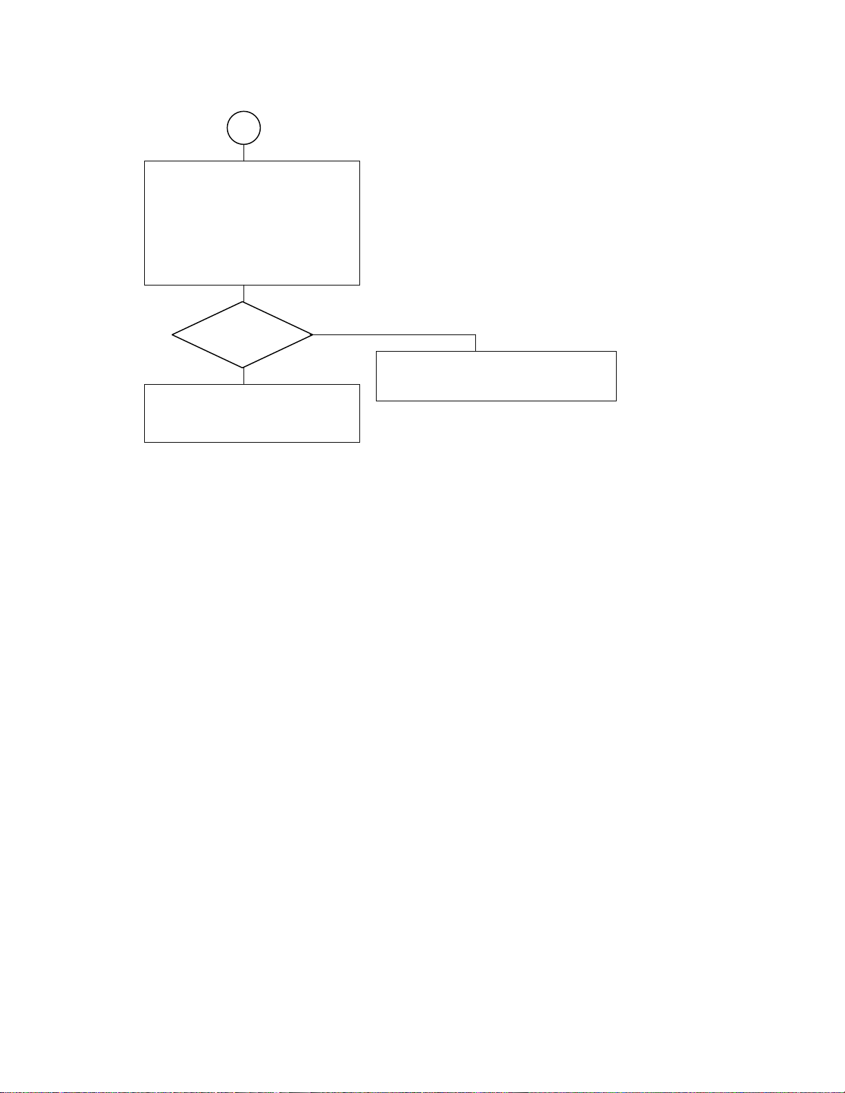
4.2.10. HDD is not recognized.
Turn on the unit. Then, check the
message displayed.
Check the error
message.
In case of5display
Replace either of the HDD flexible
cable or the main PCB assembly. Or
re-plug in.
Does the unit
display an error
message?
Y
Replace the HDD. The repair is completed.
In case of1display
Without replacing the HDD,
implement “3.3.3 Process at HDD
replacement (Transfer of F/W)”.
N
Fig.
5
display menu Fig.1display menu
23
Page 28

5. Procedure to confirm the unit’s F/W version
To display the version, perform the steps below.
1) Hold down the POWER button to turn on the unit.
2) Select [settings] → [information] → [Portable Media Center] from the start menu.
3) Confirm the version displayed. Concretely, confirm that the version displayed is as follows.
Confirm “X.XXX, YYY “ in Version X.XX(YYY).
(The display for Japan is Version X.XX(YYY.))
Confirm “MMMM.NNNNNN” in Platform Version MMMM.NNNNNN.
(The display for Japan is Platform Version MMMM.NNNNNN.)
4) Hold down the POWER button. (The unit will turn off.)
24
Page 29

6. Disassemnling Procedures/Reassembling Procedures
g
6.1. Disassemblin
Step Tool
1
2
Procedures
Photo Description Note
Turn off the battery
switch of unit (indicated
by arrow).
Rear of unit
Remove the strap
holder.
Philips
screwdriver
3
Disassemnling Procedures
4
5
Remove the screw at
the side.
Remove the screw at
the side.
Remove the screw at
the bottom.
Philipps
scredriver
Philips
screwdriver
Philips
screwdriver
6
25
Page 30

Step Tool
Photo Description Note
Remove the screw at
the bottom.
Philips
screwdriver
7
Remove the back cover.
Fix the back cover and
slide the top cover in the
8
arrow direction.
The back cover and the
top cover are removed.
9
10
Disassemnling Procedures
11
12
Remove the flexible
cable leading from the
side switch.
The cable and the rear
cover are removed.
Remove the board fixing
bracket.
Remove the board fixing
bracket.
Release the lock of
connector, lifting the
lever upward.
Tweezers
Philips
screwdriver
Philips
screwdriver
13
26
Page 31

Step Tool
Photo Description Note
The board fixing bracket
is removed.
bracket 1 piece, screw
2 pieces
14
15
16
17
Disassemnling Procedures
18
Remove the HDD
flexible cable.
The HDD is removed.
Remove the terminal
board. Remove the
screw at the bottom.
Remove the terminal
board. Remove the
screw at the side.
Release the lock, lifting
the connector lock
upward.
The terminal board is
fixed with the fixing
bracket and two screws.
Tweezers
Philips
screwdriver
Philips
screwdriver
19
20
Slide in the arrow
direction and remove
the board, lifting up.
Remove the battery
connector and battery.
27
Page 32

Step Tool
Photo Description Note
The battery is removed. Release the lock, lifting
up the lock lever of
CN1.
21
22
23
24
Disassemnling Procedures
25
Remove the SW sheet
bracket and then the
SW button.
The SW sheet bracket
is removed.
Remove the SW sheet
bracket and then the
SW button.
Remove the LCD block
and then LCD frame,
unlocking four claws.
Release the lock with
the flathead screwdriver
inserted through the
gap at the side and
remove it.
Flathead
screwdriver
Philips
screwdriver
26
27
Release the lock of
CN2 and remove the
FFC cable.
Release the lock of
CN4 and remove the
FFC cable.
28
Tweezers
Tweezers
Page 33

Step Tool
Photo Description Note
The LCD block is
removed.
28
Remove the FFC cable
of terminal board,
unlocking.
29
Remove the FFC cable
leading from SW,
unlocking.
30
Disassemnling Procedures
31
The board removal is
finished.
29
Page 34

6.2. Reassembling Procedures
Step Tool
Photo Description Note
<Board Assembling>
Be sure to lock.
Insert the FFC cable
leading from SW.
1
Affix securely the
protection tape to the
original position.
2
Connect the FFC cable
Be sure to lock.
of terminal board.
3
4
Reassembling Procedures
5
6
<Building-in of LCD
block>
Connect the FFC cable
of LCD.
Connect the FFC cable
of LCD.
Fix the LCD block to the
board and build it in the
front panel.
The board is fixed to the
front panel.
Be sure to lock. Affix
the protection tape to
the original position.
Be sure to lock.
Install the headphones
terminal side of it first.
7
30
Page 35

Step Tool
Photo Description Note
The board, LCD,
terminal board and SW
Place the SW button on
the original position.
sheet bracket are fixed
8
to the front panel.
9
10
11
Reassembling Procedures
12
Place the SW button on
the original position and
Push it in until it is
locked by the bracket.
fix the SW sheet
bracket.
Install the battery. Insert securely the
connector.
<Installing the teminal
board>
Sandwich the terminal
board fixing bracket as
shown and fix it.
Fix the terminal board
bracket with the screw.
Install the battery SW
knob indicated by
arrow.
Tweezers
Philips
screwdriver
13
14
Fix the terminal board
bracket with the screw.
the FFC cable in the
connector.
31
Be sure to lock.
Philips
screwdriver
TweezersInstall the HDD. Insert
Page 36

Step Tool
Photo Description Note
Install the board fixing
bracket with two screws.
Philips
screwdriver
15
16
17
18
Reassembling Procedures
Install the flexible cable
leading from side switch
to the connector.
Align the back cover
and the top cover with
the slide groove.
Fix the back cover.
Slide the front cover in
the arrow direction and
fix it.
Tighten the screw at the
bottom. (2 pieces)
Tweezers
Slide groove (Indicated
by arrow)
Philips
screwdriver
19
20
21
Tighten the screw at the
bottom. (2 pieces)
Tighten the screw at the
side.
32
Philips
screwdriver
Philips
screwdriver
Page 37

Step Tool
Photo Description Note
Tighten the screws at
the side.
Philips
screwdriver
22
23
Reassembling Procedures
24
Install the strap holder.
Assembling is finished.
Philips
screwdriver
33
Page 38

7. Exploded View
5
3
4
12
29
1
11
18
17
26
16
15
13
8
27
20
18
25
21
22
28
(MES60V)
2
26
28
6
10
9
19
7
24
28
23
26
14
35
33
34
36
32
31
37
30
29
38
34
Page 39

8. Parts List
y
K
K
A
(
)
R
A
gigabeat S-SERIES-(US/CA) : MES30VW ,MES60VK
Safet
Parts No. No. No.
Location Sevice Parts Description Model Remarks
P000469230 AM0007928110 TOP PANEL ASSY BLACK MES60VK
1
P000468880 AM0007928120 TOP PANEL ASSY WHITE MES30VW
P000469090 PM0025188130 BASE T1 WW30 MES60VK
2
P000469260 PM0025189130 BASE T2 WW60 MES30VW
3 P000469100 PM0025192110 HOLD BUTTON
4 P000469110 PM0025193110 HOLD RING
5 P000469120 PM0025194110 HP RING
P000469130 PM0025195110 STRAP HOLDER MES30VW
6
P000469220 PM0025449110 STRAP HOLDER T2 MES60VK
7 P000469140 PM0025196110 BATTERY BUTTON
8 P000469150 PM0025197110 LCD FRAME
9 P000468950 G8FC0001L110030 RIGID FPC ASSY
10 P000468940 G8FC0001L110020 MAIN PCB ASSY FMTV
P000469200 AM0007933110 SW BUTTON TOP ASSY-B MES60VK
11
P000468890 AM0007933120 SW BUTTON TOP ASSY-W MES30VW
12 P000468910 AM0008573110 SW TOP ASSY
P000449660 HDD1642CZ
13
P000449600 HDD1724CZ
14 P000468930 G71C0006M110 LITHIUM-ION BATTERY 1UPF383450-TBF
15 P000468970 GDM330000077 LCD BACKLIGHT CBL1759
16 P000449380 GDM330000072 LCD UNIT LTM024D362
17 P000449300 G5B001592000 HDD-FPC FBHMH1
18 P000449530 PM0023127110 HDD RUBBER
19 P000469160 PM0025207110 HDD PLATE
20 P000469210 PM0025204110 HDD-SPACER MES60VK
21 P000469180 PM0026063110 IO PLATE
22 P000469190 PM0026064110 INS IO SPACER
23 P000468900 AM0007934110 SW BUTTON SIDE ASSY
24 P000468920 AM0008574110 SW SIDE ASSY
25 P000469170 PM0025487110 INS HDD
26 P000469080 PM0024232110 INS LCD CON
27 P000469060 PM0023132110 INS LCD FPC
28 P000469070 PM0023728210 SCREW M1.4x4 TAPPING-SR
29 P000404330 PM0012147010 SCREW M1.4x2.5
P000469020 GX1C000CJ210 QUICK-START ENGLISH US/CA/AU US
30
P000469030 GX1C000CJ310 QUICK-START FRENCH CA CA
P000469040 GX1C000CJ510 SAFETY GUIDE ENGLISH US/CA/AU US
31
P000469050 GX1C000CJ610 SAFETY GUIDE FRENCH CA CA
32 P000469000 GX0C000EV210 COMPANION-CD 1.0US
33 P000449360 GDM300000214 HEAD-PHONE UX0317-01-0
34 P000441240 GDM900000706 AC-CORD VM0228A-VM0296 2M NON-PB
35 P000449310 G71C0002F111 AC-ADAPTER ADP-15HH-AE
36 P000449390 GDM900000854 USB-CABLE IQ-050253
37 P000468980 GDM900001027 USB-CONVERSION-CABLE IQ-050535B
38 P000468990 GDM900001028 AV-CABLE IQ-050932
HDD 30GB SHORT-FORM MES30VW
HDD 60GB SHORT-FORM MES60VK
1.0NA
Page 40

Specifications
Audio format • WMA (Windows Media Audio)
• WMA 9 Lossless
• MP3 (MEPG-1 Audio Layer3)
• WAV (PCM)
Video format WMV (Windows Media Video)
Photo format JPEG (9000 x 6000 max.)
Sampling frequency 8 to 48 kHz
Bit rate (Audio data) 4 to 320 kbps
(Video data) Less than or equal to 800kbps
Bit rate of the video data is that of audio + video.
Recording media S60V Internal hard disk 60 GB (*1)
S30V Internal hard disk 30 GB (*1)
Maximum Recording time (Audio da ta)
S60V Approx. 996 hours (*2) (at 128 kbps bit rate)
S30V Approx. 498 hours (*2) (at 128 kbps bit rate)
(Video data)
S60V Approx. 255 hours (*2) (at 500 kbps bit rate)
S30V Approx. 127 hours (*2) (at 500 kbps bit rate)
Continuous playback time (Audio data) Approximately 12 hours (*2): 128kbps, 44.1Hz WMA audio tracks, backlight off
(Video data) Approximately 2.5 hours (*2): 500kbps WMV video
• Excluding content protected with Windows Media DRM10
• The built-in battery fully charged using the AC adapter.
• Normal temperature (25°C), Factory-default volume
The continuous playback time is a reference value but is not guaranteed, since the actual playback time
will vary depending on the operating condition, ambient operating temperature, the number of times the
built-battery has been recharged, etc.
Even under allowable operating conditions, using the gigabeat at low temperature will result in a reduction
of the maximum continuous playback time.
Playback with the Harmonics on, WAV audio data, and WMA 9 Lossless use more battery power for
playback than MP3 and WMA. Continuous playback time will be reduced accordingly.
Operating conditions Temperature: 5 to 35°C, Humidity: 30 to 80% (RH) (No condensation)
Color screen 2.4 inch diagonal QVGA low temperature polysilicon TFT color panel (*4)
FM Radio 87.5 MHz to 107.9 MHz
USB port USB2.0/USB1.1 (*3)
Headphone / 3.5 mm jack/stereo type
V-OUT jack Load impedance 16Ω
S/N ratio 95 dB or higher
Weight (main unit only) S60V Approx. 140 g (4.9 ounces)
S30V Approx. 127 g (4.45 ounces)
External dimensions S60V Approx. 59.9 mm x 16.2 mm x 99.9 mm (2.35 inches x 0.63 inches x 3.93 inches)
(excluding projections) (width x height x depth)
S30V Approx. 59.9 mm x 13.2 mm x 99.9 mm (2.35 inches x 0.51 inches x 3.93 inches)
(width x height x depth)
Power Rechargeable lithium-ion battery, AC adapter, USB charging
AC adapter Type name: ADP-15HH A
Input power condition: 100 to 240 VAC, 50/60Hz
Rated output: 5V DC, 3A
Page 41

*1: 1 Gigabyte(GB) means 109= 1,000,000,000 bytes using powers of 10. The operating system of the gigabeat and certain computer
30
operating systems, however, calculate storage capacity using powers of 2 for the definition of 1 GB =2
= 1,073,741,824 bytes
and therefore show less storage capacity. Available storage capacity is also less as the gigabeat includes a pre-installed operating
system, pre-installed software applications, and/or media content. Actual formatted capacity may vary.
*2: These values are for reference purposes only and may vary.
*3: It is necessary to operate the USB2.0 interface with the USB2.0 interface preinstalled or extended PC. It operates as USB1.1 when
connecting it with the USB1.1 interface.
*4: The color LCD is made with extremely high-precision technology. There may be the existence of display (pixels) that might not light or
might be lit all the time; however, please note that this does not constitute malfunction of the product and is not covered by your
warranty.
Note
• This product complies with the above specifications.
• Design and specifications are subject to change without notice.
• This product may not be compatible with features and/or specifications that may be added in the future.
• The illustrations and screen displays appearing in this manual may differ somewhat from the actual appearance.
• The display position and other aspects of the icons are subject to change.
Combination of Sampling Frequency and Bit Rate
The tracks that can be played on the gigabeat have the following combinations of sampling frequency and bit rate. Tracks with another
combination may not play properly.
MP3 (stereo)
Sampling frequency: 8, 16, 22.05, 44.1, 48 kHz
Bit rate: 32 to 320 kbps
MP3 (mono)
Sampling frequency: 8, 11, 16, 22.05, 32, 44.1 kHz
Bit rate: 16 to 64 kbps
WMA (stereo)
Sampling frequency: 8, 16, 22.05, 32, 44.1, 48 kHz
Bit rate: CBR 32 to 320 kbps, VBR 32 to 355 kbps
WMA (mono)
Sampling frequency: 8, 11, 16, 22.05, 32, 44.1 kHz
Bit rate: CBR 5 to 48 kbps
WMA (VOICE)
Sampling frequency: 8, 11, 16, 22.05, 32, 44.1kHz
Bit rate: 4 to 20 kbps
WAV (stereo/mono)
Sampling frequency: 8, 16, 22.05, 32, 44.1, 48 kHz
Bits rate: Uncompressed
WMA 9 Lossless
Sampling frequency: 8, 16, 22.05, 32, 44.1, 48 kHz
Page 42

PC Requirements (*1)
Q
Operating System : Microsoft® Windows® XP Home Edition / XP
Professional / XP Media Center Edition
(Windows XP Service Pack 2 is recommended.)
Q
CPU : 300MHz or faster (1.5GHz is recommended)
Q
RAM : 128MB or more (512MB is recommended)
Q
Hard disk space : 100MB or more
Q
Interface : USB 2.0 / USB 1.1 (*2)
Q
Others : CD-ROM Drive
*1: Only PCs with pre-installed operating systems are supported. Macintosh® computers and OS are not supported.
*2: In order for the device to transfer information using USB 2.0, the USB 2.0 protocol must be installed on the PC. If the PC can only
transfer at USB 1.1 speeds, then the device will transfer information using USB 1.1.
Perform the following procedures before using the gigabeat. Windows Media Player 10 and the Owner’s Manual are installed.
To transfer music, video and photo data to the gigabeat via PC, use Windows Media Player 10.
Note
• Even when Windows Media Player 10 is already installed on the PC, continue the installation procedure. Files necessary to work with
the gigabeat will be installed on the PC.
1 Insert the included CD-ROM into the PC.
2 Click the “Install Windows Media Player 10” button.
Even when Windows Media Player 10 is already installed on the PC, continue the installation procedure. Files necessary to work with
the gigabeat will be installed on the PC.
3 Follow the on screen instructions
Trademarks
• gigabeat and Plus Touch are trademarks of Toshiba Corporation.
• Microsoft, Windows, Windows Media and Windows Mobile are either registered trademarks or trademarks of Microsoft Corporation in
the United States and/or other countries.
• Adobe, the Adobe logo and Reader are trademarks or registered trademarks of Adobe Systems Incorporated in the United States and/or
other countries.
• Macintosh is a registered trademark of Apple Computer, Inc.
• The product names referred to in this manual may be registered trademarks or trademarks of their respective companies.
Page 43

 Loading...