


 DIGITAL VIDEO
COMBINATION FLAT COLOR TELEVISION AND DVD VIDEO
PLAYER
MD20F51
MD24F51
OWNER’S MANUAL
Illustration of MD24F51
©2005 Toshiba Corporation
Before operating the unit, please read this manual thoroughly.
Introduction
Connections
Basic setup
TV operation
Basic playback
Advanced playback
Function setup
Others
2
13
18
20
28
31
41
47
5S10101A [E] (Cover) |
1 |
2/5/05, 9:41 AM |
Introduction
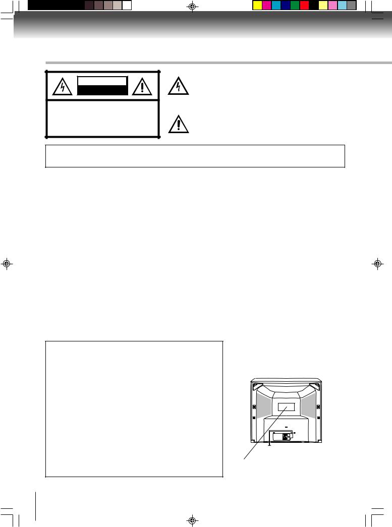
IMPORTANT SAFEGUARDS
CAUTION
RISK OF ELECTRIC SHOCK
DO NOT OPEN
CAUTION: TO REDUCE THE RISK OF ELECTRIC SHOCK, DO NOT REMOVE COVER (OR BACK). NO USER-SERVICEABLE PARTS INSIDE. REFER SERVICING TO QUALIFIED SERVICE PERSONNEL.
The lightning flash with arrowhead symbol, within an equilateral triangle is intended to alert the user to the presence of uninsulated dangerous voltage within the product's
enclosure that may be of sufficient magnitude to constitute a risk of electric shock.
The exclamation point within an equilateral triangle is intended to alert the user to the presence of important operating and maintenance (servicing) instructions in the literature accompanying the appliance.
WARNING: TO PREVENT FIRE OR SHOCK HAZARD, DO NOT EXPOSE THIS APPLIANCE TO RAIN OR MOISTURE.
WARNING: This equipment has been tested and found to comply with the limits for a Class B digital device, pursuant to Part 15 of the FCC Rules. These limits are designed to provide reasonable protection against harmful interference in a residential installation. This equipment generates, uses and can radiate radio frequency energy and, if not installed and used in accordance with the instructions, may cause harmful interference to radio communications.
However, there is no guarantee that interference will not occur in a particular installation. If this equipment does cause harmful interference to radio or television reception, which can be determined by turning the equipment off and on, the user is encouraged to try to correct the interference by one or more of the following measures:
-Reorient or relocate the receiving antenna.
-Increase the distance between the equipment and receiver.
-Connect the equipment into an outlet on a circuit different from that to which the receiver is connected.
-Consult the dealer or an experienced radio/TV technician for help.
CAUTION: Changes or modifications not expressly approved by the party responsible for compliance with the FCC (Federal Communications Commission) Rules could void the user's authority to operate this equipment.
COPYRIGHT: It is permissible to record television programs, films, video tapes and other material only in the event that third party copyrights and other rights are not violated.
CAUTION:
THIS DIGITAL VIDEO PLAYER EMPLOYS A LASER SYSTEM.
TO ENSURE PROPER USE OF THIS PRODUCT, PLEASE READ THIS OWNER'S MANUAL CAREFULLY AND RETAIN FOR FUTURE REFERENCE. SHOULD THE UNIT REQUIRE MAINTENANCE, CONTACT AN AUTHORIZED SERVICE LOCATION.
USE OF CONTROLS, ADJUSTMENTS OR THE PERFORMANCE OF PROCEDURES OTHER THAN THOSE SPECIFIED HEREIN MAY RESULT IN HAZARDOUS RADIATION EXPOSURE.
TO PREVENT DIRECT EXPOSURE TO LASER BEAM, DO NOT TRY TO OPEN THE ENCLOSURE. VISIBLE LASER RADIATION MAY BE PRESENT WHEN THE ENCLOSURE IS OPENED. DO NOT STARE INTO BEAM.
Location of the required Marking
The rating sheet and the safety caution are on the rear of the unit.
Illustration of MD24F51
CERTIFICATION: COMPLIES WITH
FDA RADIATION PERFORMANCE STANDARDS, 21 CFR SUBCHAPTER J.
2
5S10101A [E] (P02-05) |
2 |
2/5/05, 9:41 AM |
|
|
|
|
|
|
|
|
|
|
|
|
|
|
|
|
|
|
|
|
|
|
|
|
|
|
|
|
|
|
|
|
|
|
|
|
|
|
|
|
|
|
|
|
|
|
|
|
|
|
|
|
|
|
|
|
|
|
|
|
|
|
|
|
|
|
|
|
|
|
|
|
|
|
|
|
|
|
|
|
|
|
|
|
|
|
|
|
1. |
READ INSTRUCTIONS |
|
|
|
|
|
||||
|
|
|
|
All the safety and operating instructions should be read before the unit is operated. |
|
|
|
|
|
|
2. |
RETAIN INSTRUCTIONS |
|
|
|
|
|
||||
|
|
|
|
The safety and operating instructions should be retained for future reference. |
|
|
|
|
|
|
|
|
|
|
Introduction |
|
|
|
|||
|
|
|
|
All operating and use instructions should be followed. |
|
|
|
|||
|
|
|
3. HEED WARNINGS |
|
|
|
|
|
||
|
|
|
|
All warnings on the unit and in the operating instructions should be adhered to. |
|
|
|
|
|
|
|
|
|
4. FOLLOW INSTRUCTIONS |
|
|
|
|
|
||
5. |
CLEANING |
|
|
|
|
|
||||
|
|
|
|
Unplug this unit from the wall outlet before cleaning. Do not use liquid cleaners or aerosol cleaners. |
|
|
|
|
|
|
|
|
|
|
Use a damp cloth for cleaning the exterior cabinet only. |
|
|
|
|
|
|
6. ATTACHMENTS
The manufacturer of this unit does not make any recommendations for attachments, as they may cause
hazards.
7.WATER AND MOISTURE
Do not use this unit near water. For example, near a bathtub, washbowl, kitchen sink, laundry tub, in a wet basement, or near a swimming pool.
PORTABLE CART WARNING (symbol provided by RETAC)
8. ACCESSORIES
Do not place this unit on an unstable cart, stand, tripod, bracket, or table.
The unit may fall, causing serious injury, and serious damage to the unit. 8A. An appliance and cart combination should be moved with care. Quick stops,
excessive force, and uneven surfaces may cause the appliance and cart
combination to overturn.
S3126A
9. VENTILATION
Slots and openings in the cabinet back or bottom are provided for ventilation, and to ensure reliable operation of the unit, and to protect it from overheating.
These openings must not be blocked or covered. The openings should never be blocked by placing the unit on a bed, sofa, rug, or other similar surface. This unit should never be placed near or over a radiator or heat source. This unit should not be placed in a built-in installation such as a bookcase or rack unless proper ventilation is provided or the manufacturer’s instructions have been adhered to.
10. POWER SOURCE
This unit should be operated only from the type of power source indicated on the rating plate. If you are not sure of the type of power supply to your home, consult your appliance dealer or local power company. For units intended to operate from battery power, or other sources, refer to the respective pages on this Owner's Manual for their operating instructions.
11. GROUNDING OR POLARIZATION
This unit is equipped with a polarized alternating-current line plug (a plug having one blade wider than the other). This plug will fit into the power outlet only one way. This is a safety feature. If you are unable to insert the plug fully into the outlet, try reversing the plug. If the plug should still fail to fit, contact your electrician to replace your obsolete outlet. Instead of the polarized alternating-current line plug, your unit may be equipped with a 3-wire grounding-type plug (a plug having a third (grounding) pin). This plug will only fit into a grounding-type power outlet. This too, is a safety feature. If you are unable to insert the plug into the outlet, contact your electrician to replace your obsolete outlet.
Do not defeat the safety purpose of the grounding-type plug.
12. POWER-CORD PROTECTION
Power-supply cords should be routed so that they are not likely to be walked on or pinched by items placed upon or against them, paying particular attention to cords at plugs, convenience receptacles, and the point where they exit from the appliance.
13. LIGHTNING
To protect your unit from a lightning storm, or when it is left unattended and unused for long periods of time, unplug it from the wall outlet and disconnect the antenna or cable system. This will prevent damage to the unit due to lightning and power line surges.
3
5S10101A [E] (P02-05) |
3 |
2/5/05, 9:41 AM |

Introduction
IMPORTANT SAFEGUARDS (Continued)
14.POWER LINES
An outside antenna system should not be located in the vicinity of overhead power lines or other electric light or power circuits, or where it can fall onto or against such power lines or circuits. When installing an outside antenna system, extreme care should be taken to keep from touching such power lines or circuits, as contact with them might be fatal.
15.OVERLOADING
Do not overload wall outlets and extension cords, as this can result in a risk of fire or electric shock.
16.OBJECT AND LIQUID ENTRY
Do not push objects through any openings in this unit, as they may touch dangerous voltage points or short out parts that could result in fire or electric shock. Never spill or spray any type of liquid into the unit.
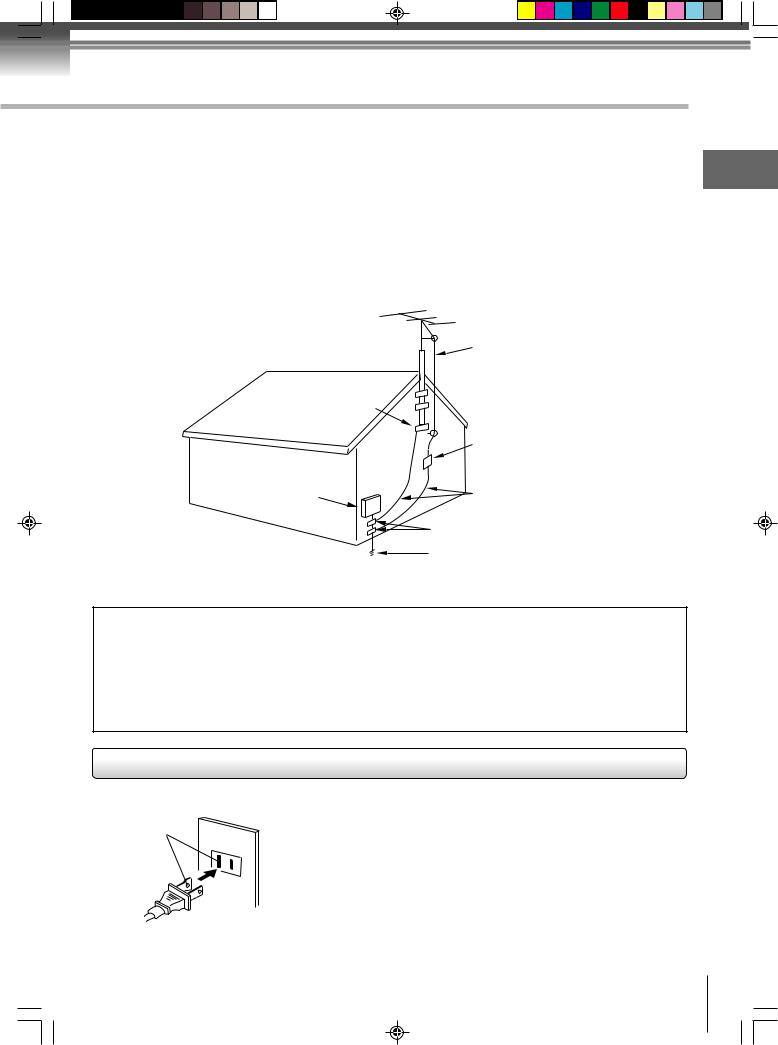
17.OUTDOOR ANTENNA GROUNDING
If an outside antenna or cable system is connected to the unit, be sure the antenna or cable system is grounded to provide some protection against voltage surges and built-up static charges, Section 810 of the National Electrical Code (NEC), ANSI/NFPA 70, provides information with respect to proper grounding of the mast and supporting structure, grounding of the lead-in wire to an antenna discharge unit, size of grounding conductors, location of antenna discharge unit, connection to grounding electrodes, and requirements for the grounding electrode.
18.SERVICING
Do not attempt to service this unit yourself as opening or removing covers may expose you to dangerous voltage or other hazards. Refer all servicing to qualified service personnel.
For example:
a.When the power-supply cord or plug is damaged.
b.If liquid has been spilled, or objects have fallen into the unit.
c.If the unit has been exposed to rain or water.
d.If the unit does not operate normally by following the operating instructions. Adjust only those controls that are covered by the operating instructions, as an improper adjustment of other controls may result in damage and will often require extensive work by a qualified technician to restore the unit to its normal operation.
e.If the unit has been dropped or the cabinet has been damaged.
f.When the unit exhibits a distinct change in performance, this indicates a need for service.
19.REPLACEMENT PARTS
When replacement parts are required, be sure the service technician uses replacement parts specified by the manufacturer or those that have the same characteristics as the original part.
Unauthorized substitutions may result in fire, electric shock or other hazards.
20.SAFETY CHECK
Upon completion of any service or repairs to this unit, ask the service technician to perform safety checks to determine that the unit is in proper operating condition.
21.HEAT
The product should be situated away from heat sources such as radiators, heat registers, stoves, or other products (including amplifiers) that produce heat.
22.DISC TRAY
Keep your fingers well clear of the disc tray as it is closing. It may cause serious personal injury.
23.CONNECTING
When you connect the product to other equipment, turn off the power and unplug all of the equipment from the wall outlet. Failure to do so may cause an electric shock and serious personal injury. Read the owner's manual of the other equipment carefully and follow the instructions when making any connections.
24.SOUND VOLUME
Reduce the volume to the minimum level before you turn on the product. Otherwise, sudden high volume sound may cause hearing or speaker damage.
25.SOUND DISTORTION
Do not allow the product output distorted sound for a longtime. It may cause speaker overheating and fire.
26.HEADPHONES
When you use the headphones, keep the volume at a moderate level. If you use the headphones continuously with high volume sound, it may cause hearing damage.
27.LASER BEAM
4 |
Do not look into the opening of the disc tray or ventilation opening of the product to see the source of the |
laser beam. It may cause sight damage. |
5S10101A [E] (P02-05) |
4 |
2/5/05, 9:41 AM |
28. DISC
Do not use a cracked, deformed, or repaired disc. These discs are easily broken and may cause serious personal injury and product malfunction.
29. NOTE TO CABLE TV SYSTEM INSTALLER
This reminder is provided to call the Cable TV system installer’s attention to Article 820-40 of the NEC that |
|
|||||
provides guidelines for proper grounding and, in particular, specifies that the cable ground shall be con- |
Introduction |
|||||
nected to the grounding system of the building, as close to the point of cable entry as practical. |
||||||
|
||||||
EXAMPLE OF ANTENNA GROUNDING AS PER THE |
|
|||||
NATIONAL ELECTRICAL CODE |
|
|||||
|
|
|
|
ANTENNA LEAD |
|
|
|
|
|
|
IN WIRE |
|
|
|
GROUND |
|
||||
|
CLAMP |
|
||||
|
|
|
|
ANTENNA |
|
|
|
|
|
|
DISCHARGE UNIT |
|
|
|
|
|
|
(NEC SECTION 810-20) |
|
|
ELECTRIC SERVICE |
|
|
|
GROUNDING CONDUCTORS |
|
|
|
|
|
|
|||
EQUIPMENT |
|
|
|
(NEC SECTION 810-21) |
|
|
|
|
|
|
|||
|
|
GROUND CLAMPS |
|
|
|
NEC-NATIONAL ELECTRICAL CODE |
|
POWER SERVICE GROUNDING |
|
ELECTRODE SYSTEM |
|
S2898A |
|
|
|
(NEC ART 250, PART H) |
|
|
|
IMPORTANT RECYCLING INFORMATION
This product uses both Cathode Ray Tube (CRT) and other components that contain lead. In your community there might be regulations that require you to dispose these materials properly under environmental considerations. Please contact your local authorities, or the Electronic Industries Alliance (http://www.eiae.org) for disposal or recycling information.
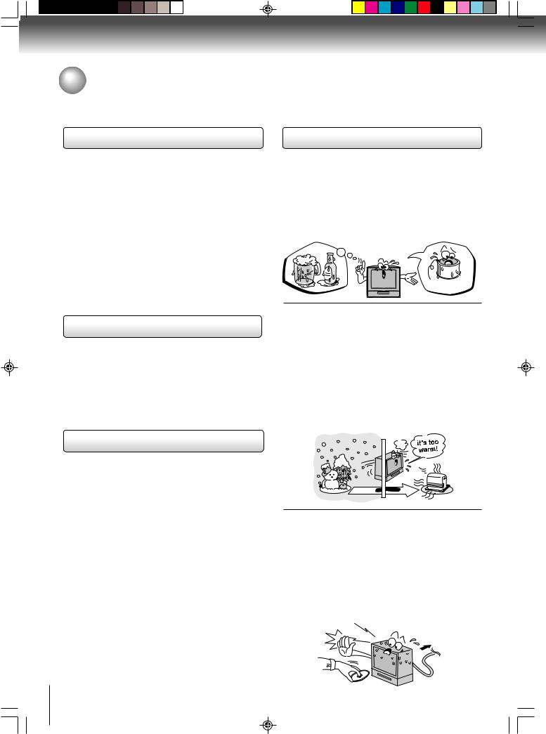
Power source
AC Outlet
Wider Hole
and Blade
Polarized AC Cord Plug
(One blade is wider than the other.)
TO USE AC POWER SOURCE
Use the AC polarized line cord provided for operation on AC. Insert the AC cord plug into a standard 120V 60Hz polarized AC outlet.
Notes:
•Never connect the AC line cord plug to other than the specified voltage (120V 60Hz). Use the attached power cord only.
•If the polarized AC cord does not fit into a non-polarized AC outlet, do not attempt to file or cut the blade. It is the user’s responsibility to have an electrician replace the obsolete outlet.
•If you cause a static discharge when touching the unit and the unit fails to function, simply unplug the unit from the AC outlet and plug it back in. The unit should return to normal operation.
•If the AC cord plug is plugged in for the first time, wait for approx. 5 seconds before pressing the POWER button.
5
5S10101A [E] (P02-05) |
5 |
2/5/05, 9:41 AM |
Introduction
Precautions
Notes on handling
3When shipping the unit, the original shipping carton and packing materials come in handy. For maximum protection, repack the unit as it was originally packed at the factory.
3Do not use volatile liquids, such as insect spray, near the unit. Do not leave rubber or plastic products to contact the unit for prolonged period. They will leave marks on the finish.
3The top and rear panels of the unit may become warm after a long period of use. This is not a malfunction.
3When the unit is not in use, be sure to remove the disc and turn off the power.
3If you do not use the unit for a long period, the unit may not function properly in the future. Turn on and use the unit occasionally.
Notes on locating
3Place the unit on a level surface. Do not use it on a shaky or unstable surface such as a wobbling table or inclined stand. The loaded disc may become disaligned and damage the unit.
3When you place this unit near a TV, radio, or VCR, the playback picture may become poor and the sound may be distorted. In this case, place the unit away from the TV, radio or VCR.
Notes on cleaning
Use a soft, dry cloth for cleaning.  Use a dry cloth to wipe it dry.
Do not use any type of solvent, such as thinner and benzine, as they may damage the surface of the unit.  If you use a chemical saturated cloth to clean the unit, follow that product’s instructions.
6
Notes on moisture condensation
Moisture condensation damages the unit. Please read the following carefully.
Moisture condensation occurs, for example, when you pour a cold drink into a glass on a warm day. Drops of water form on the outside of the glass. In the same way, moisture may condense on the optical pick-up lens inside this unit, one of the most crucial internal parts of the unit.
|
|
|
|
||
|
|
|
|
|
|
|
|
|
|
||
|
|
|
|
|
|
|
|
|
|
||
|
|
|
|
||
3 Moisture condensation occurs during the following cases.
 When you bring the unit directly from a cold place to a warm place.
 When you use the unit in a room where you just turned on the heater, or a place where the cold wind from the air conditioner directly hits the unit.
 In summer, when you use the unit in a hot and humid place just after you move the unit from an air conditioned room.
 When you use the unit in a humid place.
3Do not use the unit when moisture condensation may occur.
If you use the unit in such a situation, it may damage discs and internal parts. Remove the disc, connect the power cord of the unit to the wall outlet, turn on the unit, and leave it for two or three hours. After two or three hours, the unit will have warmed up and evaporated any moisture. Keep the unit connected to the wall outlet and moisture condensation will seldom occur.
Wait!
Wall outlet
5S10101A [E] (P06-07) |
6 |
2/5/05, 9:41 AM |
Notes on discs
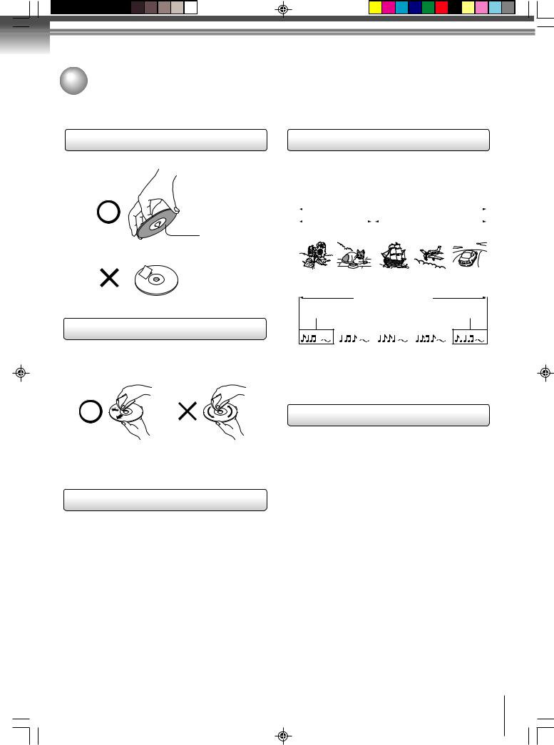
On handling discs
 Do not touch the playback side of the disc.
Playback side
 Do not attach paper or tape to discs.
On cleaning discs
 Fingerprints and dust on the disc cause picture and sound deterioration. Wipe the disc from the center outwards with a soft cloth. Always keep the disc clean.
 Do not use any type of solvent such as thinner, benzine, commercially available cleaners or antistatic spray for vinyl LPs. It may damage the disc.
On storing discs
 Do not store discs in a place subject to direct sunlight or near heat sources.
 Do not store discs in places subject to moisture and dust such as a bathroom or near a humidifier.
  Store discs vertically in a case. Stacking or placing objects on discs outside of their case may cause warping.
Structure of disc contents |
|
|||||||||||||||||||||||||||||||
Introduction |
||||||||||||||||||||||||||||||||
Audio CDs are divided into tracks. |
|
|
|
|
|
|
|
|
|
|
|
|||||||||||||||||||||
Normally, DVD video discs are divided into titles, and |
|
|||||||||||||||||||||||||||||||
the titles are sub-divided into chapters. Video CDs and |
|
|||||||||||||||||||||||||||||||
DVD video disc |
|
|
|
|
|
|
|
|
|
|
|
|
||||||||||||||||||||
|
|
|
|
|
|
|
|
|
|
DVD video disc |
|
|
|
|
|
|
|
|
|
|
||||||||||||
|
|
|
|
|
|
|
|
|
|
|
|
|
|
|
|
|
|
|||||||||||||||
|
|
|
|
|
|
|
|
|
|
|
|
|
|
|
|
|
|
|
|
|
|
|
|
|
|
|
|
|
|
|
||
|
|
|
|
Title 1 |
|
|
|
|
|
|
|
|
|
|
|
|
|
Title 2 |
|
|
|
|
|
|
|
|
||||||
|
Chapter |
|
|
|
|
|
Chapter 1 |
|
|
|
||||||||||||||||||||||
|
|
|
|
|
|
|
|
|
|
|
|
|
||||||||||||||||||||
|
1 Chapter 2 |
|
|
Chapter 2 Chapter 3 |
|
|
|
|||||||||||||||||||||||||
|
|
|
|
|
|
|
|
|
|
|
|
|
|
|
|
|
|
|
|
|
|
|
|
|
|
|
|
|
|
|
|
|
|
|
|
|
|
|
|
|
|
|
|
|
|
|
|
|
|
|
|
|
|
|
|
|
|
|
|
|
|
|
|
|
|
|
|
|
|
|
|
|
|
|
|
|
|
|
|
|
|
|
|
|
|
|
|
|
|
|
|
|
|
|
|
|
|
|
|
|
|
|
|
|
|
|
|
|
|
|
|
|
|
|
|
|
|
|
|
|
|
|
|
|
|
|
|
|
|
|
|
Video CD/Audio CD
Video CD/Audio CD
Track 1 |
Track 2 |
Track 3 |
Track 4 |
Track 5 |
|||||
|
|
|
|
|
|
|
|
|
|
|
|
|
|
|
|
|
|
|
|
Each title, chapter or track is assigned a number, which is called “title number”, “chapter number” or “track number” respectively.
There may be discs that do not have these numbers.
Notes on copyright
The unauthorized recording, use, distribution, or revision of copyrighted materials including, without limitation, television programs, videotapes, and DVDs, is prohibited under the Copyright Laws of the United States and other countries, and may subject you to civil and criminal liability.
This product incorporates copyright protection technology that is protected by method claims of certain U.S. patents and other intellectual property rights owned by Macrovision Corporation and other rights owners. Use of this copyright protection technology must be authorized by Macrovision Corporation, and is intended for home and other limited viewing uses only unless otherwise authorized by Macrovision Corporation. Reverse engineering or disassembly is prohibited.
7
5S10101A [E] (P06-07) |
7 |
2/5/05, 9:41 AM |
Introduction
Notes on discs (Continued)
About this owner’s manual
This owner’s manual explains the basic instructions of this unit. Some DVD video discs are produced in a manner that allows specific or limited operation during playback. As such, the unit may not respond to all operating commands. This is not a defect in the unit. Refer to instruction notes of discs.
“  ” may appear on the TV screen during operation.
A “ ” means that the operation is not permitted by the unit or the disc.
For example, sometimes it is unable to stop the playback of copyright message of the disc when the STOP (3) button is pressed. Alternatively, the “ ” may also indicate that the feature is not available for the disc.
Notes on region numbers
The region number of this unit is 1. If region numbers, which stand for their playable area, are printed on your
DVD video disc and you do not find 1 or ALL , disc playback will not be allowed by the player. (In this case, the unit will display a message on-screen.)
On Video CDs
This DVD supports Video CDs equipped with the PBC (Version 2.0) function. (PBC is the abbreviation of Playback Control.) You can enjoy two playback variations depending on types of discs.
•Video CD not equipped with PBC function (Version 1.1)
Sound and movie can be played on this DVD in the same way as an audio CD.
•Video CD equipped with PBC function (Version 2.0)
In addition to operation of a Video CD not equipped with the PBC function, you can enjoy playback of interactive software with search function by using the menu displayed on the TV screen (Menu Playback). Some of the functions described in this owner’s manual may not work with some discs.
8
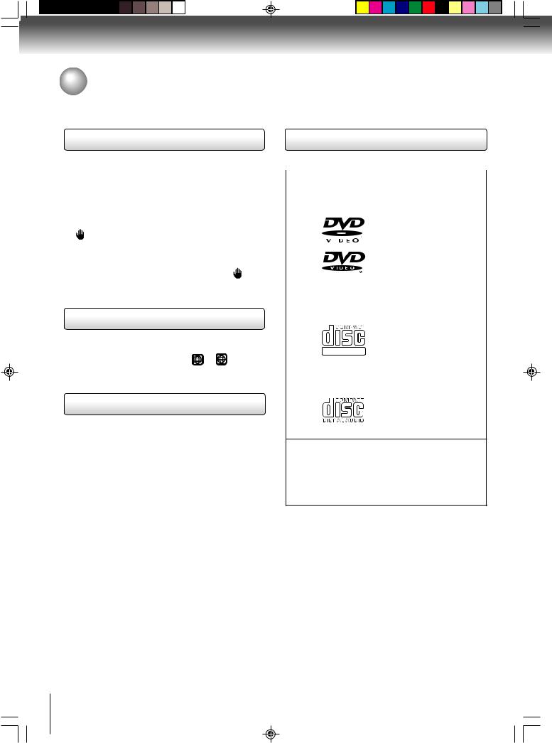
Playable discs
This unit can play the following discs.
|
Disc Mark |
Contents |
Disc |
Maximum |
|
|
Size |
playback time |
|||
|
|
|
|
||
|
|
|
|
|
|
|
|
|
|
|
Approx. 4 hours |
|
|
|
|
|
(single sided disc) |
|
|
|
Audio |
12 cm |
|
|
|
|
Approx. 8 hours |
||
|
|
|
|
||
|
|
|
+ |
|
|
DVD |
|
|
|
(double sided disc) |
|
|
|
Video |
|
||
video |
|
|
|
|
|
|
|
(moving |
|
|
|
discs |
|
|
|
Approx. 80 minutes |
|
|
|
pictures) |
|
||
|
|
|
|
|
(single sided disc) |
|
|
|
|
8 cm |
|
|
|
|
|
Approx. 160 minutes |
|
|
|
|
|
|
|
|
|
|
|
|
(double sided disc) |
|
|
|
|
|
|
|
|
|
Audio |
12 cm |
Approx. 74 minutes |
|
|
|
|
|
|
Video |
|
|
+ |
|
|
|
|
Video |
|
|
|
CDs |
|
|
|
|
|
DIGITAL VIDEO |
(moving |
|
|
||
|
|
|
|||
|
pictures) |
|
|
||
|
|
|
8 cm |
Approx. 20 minutes |
|
|
|
|
|
||
|
|
|
|
|
|
|
|
|
|
12 cm |
Approx. 74 minutes |
Audio |
|
|
Audio |
|
|
CDs |
|
|
8 cm |
|
|
|
|
|
|
||
|
|
|
|
(CD |
Approx. 20 minutes |
|
|
|
|
single) |
|
|
|
|
|
|
|
The following discs are also available.  DVD-R/RW discs of DVD video format
 CD-R/CD-RW discs of CD-DA, Video CD, MP3, WMA or JPEG format
 Kodak Picture CD and FUJICOLOR CD format Some of these discs may be incompatible.
•You cannot play discs other than those listed above.
•You cannot play discs of DVD-RAM, DVD-ROM, Photo CD, etc., or non standardized discs even if they may be labeled as above.
•Some CD-R/RWs cannot be played back depending on the recording conditions.
•This unit uses the NTSC color system, and cannot play DVD video discs recorded in any other color system (PAL, SECAM, etc.).
Because of problems and errors that can occur during the creation of DVD software and/or the manufacture of DVD discs, Toshiba cannot guarantee that this player will play every feature of every DVD bearing the DVD logo. As one of the creators of DVD technology, Toshiba DVD players are manufactured using the highest standards of quality, and as a result, such incompatibilities are rare. If you happen to experience any difficulty playing a DVD on a Toshiba DVD player, please feel free to call our Contact listed in “How to Obtain Warranty Service” (see page 53).
5S10101A [E] (P08-12) |
8 |
2/5/05, 9:41 AM |

Contents |
|
Introduction |
|
IMPORTANT SAFEGUARDS ............................ |
2 |
Precautions ....................................................... |
6 |
Notes on discs ................................................... |
7 |
Contents ............................................................ |
9 |
Identification of controls .................................. |
10 |
Connections |
|
Antenna connections ....................................... |
13 |
Cable TV connections ..................................... |
14 |
Connecting to optional equipment ................... |
15 |
Basic setup |
|
Starting setup .................................................. |
18 |
Setting the language ....................................... |
19 |
TV operation |
|
TV operation .................................................... |
20 |
Closed captions ............................................... |
22 |
To memorize channels .................................... |
23 |
Setting the V-Chip ........................................... |
24 |
Picture control adjustment ............................... |
26 |
Adjusting the picture preference ..................... |
26 |
Sound control adjustment ............................... |
27 |
Stereo and Second Audio Program (SAP) ...... |
27 |
Basic playback |
|
Playing a disc .................................................. |
28 |
Advanced playback |
|
Zooming ......................................................... |
31 |
Locating desired scene .................................. |
31 |
Marking desired scenes ................................. |
32 |
Repeat playback ............................................. |
33 |
A-B Repeat playback ...................................... |
33 |
Program playback .......................................... |
34 |
Random playback........................................... |
34 |
Changing angles ............................................ |
35 |
Title selection ................................................. |
35 |
DVD menu ...................................................... |
35 |
Changing soundtrack language ..................... |
36 |
Subtitles ......................................................... |
36 |
Disc status ...................................................... |
37 |
To turn off the PBC ........................................ |
37 |
MP3/WMA/JPEG CD information ................... |
38 |
MP3/WMA CD playback ................................. |
39 |
JPEG playback ............................................... |
40 |
Function setup |
|
Customizing the function settings .................. |
41 |
Temporary disabling of rating level |
|
by DVD disc ................................................... |
46 |
Others |
|
Language code list ......................................... |
47 |
Troubleshooting ............................................. |
48 |
Reception disturbances .................................. |
50 |
Specifications ................................................. |
51 |
Limited warranty ............................................. |
52 |
Introduction
9
5S10101A [E] (P08-12) |
9 |
2/5/05, 9:41 AM |
Introduction
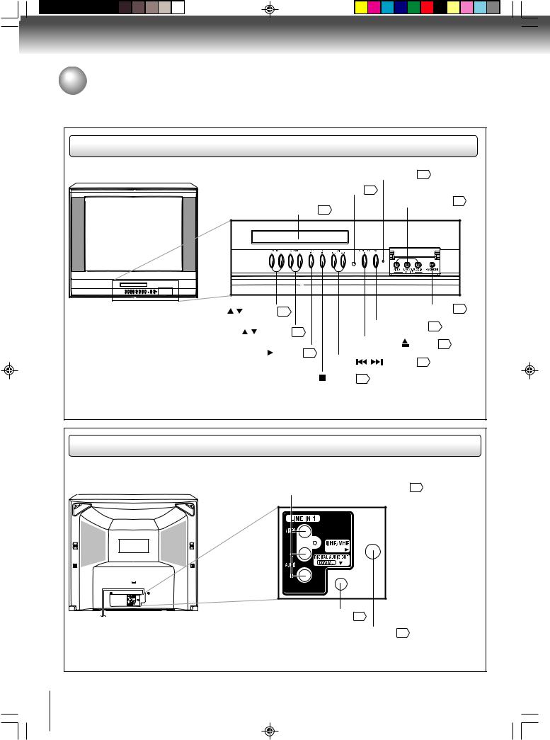
Identification of controls
See the page in  for details.
Front
Illustration of MD24F51 |
POWER indicator 20 |
|
|
|
Remote sensor 12 AUDIO (L/R)/VIDEO IN |
|
jacks (LINE IN 2) 15 |
|
Disc tray 28 |
VOLUME ( / ) buttons |
20 |
HEADPHONE jack 21 |
|
||
CHANNEL ( / ) buttons |
POWER button 18 |
|
21 |
||
|
|
OPEN/CLOSE ( ) button 28 |
PLAY ( |
) button 28 |
|
|
|
SKIP ( / ) buttons 30 |
|
|
STOP( ) button 28 |
Model MD24F51 has a door on the front panel. Please open it to access the HEADPHONE jack and the AUDIO (L/R)/
VIDEO IN (LINE IN) jacks.
Rear |
|
|
|
|
Illustration of MD24F51 |
|
|
15 |
|
|
|
|||
|
|
16 |
|
|
|
|
|
13 |
|
10 |
|
|
|
|
5S10101A [E] (P08-12) |
10 |
2/5/05, 9:41 AM |
|
|

Remote control
The instructions in this manual describe the function on the remote control. See the page in  for details.
|
28 |
|
|
28 |
|
#$%& &'( %) |
|
20 |
%)%& # *+ ,- |
||
. %$ *+ ,- |
24 |
|
|
21 |
|
|
|
21 |
|
36 |
|
|
15 |
|
|
31 |
|
|
33 |
|
#$%& # * |
- |
18 |
|
19 |
|
|
41 |
|
|
28 |
|
|
29 |
|
|
21 |
|
" |
|
30 |
|
30 |
|
|
|
30 |
|
35 |
|
|
35 |
|
*DVD MENU button
Use the DVD MENU button to display the menu included on many DVD video discs.
To operate a menu, follow the instructions in “DVD menu.” 35
18
21
31
20
27 36
21
35
18
18
28
22
" |
30 |
!! |
30 |

 30
30
" 32
15
33
41
Introduction
11
5S10101A [E] (P08-12) |
11 |
2/5/05, 9:41 AM |
Introduction
Identification of controls (Continued)
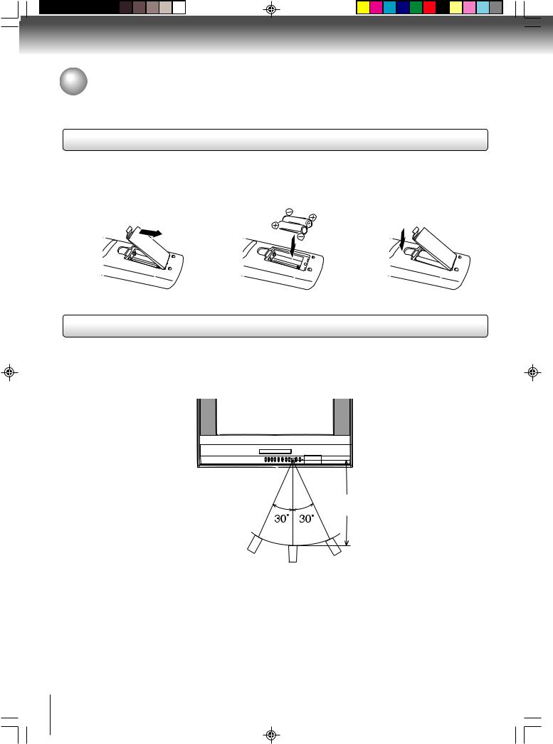
Inserting batteries
1 Open the battery compartment cover in the direction of the arrow.
Operation
2 Install two “R03/AAA” |
3 Replace the compartment |
batteries (supplied), paying |
cover. |
attention to the polarity |
|
diagram in the battery |
|
compartment. |
|
•Aim the remote control at the remote sensor and press control buttons to operate.
•Operate the remote control within 30° angle on either side of the remote sensor, up to a distance of approx. 5 meters.
Illustration of MD24F51
Approx. 5 meters
Caution:
• Never throw batteries into a fire.
Notes:
•Be sure to use AAA size batteries.
•Dispose of batteries in a designated disposal area.
•Attention should be drawn to the environmental aspects of battery disposal.
•Do not mix different battery types or combine used batteries with new ones.
•If the remote control does not operate correctly, or if the operating range becomes reduced, replace both batteries with new ones.
•If the batteries are dead or if you will not be using the remote control for a long time, remove the batteries to prevent battery acid from leaking into the battery compartment.
12
5S10101A [E] (P08-12) |
12 |
2/5/05, 9:41 AM |
Connections
Antenna connections
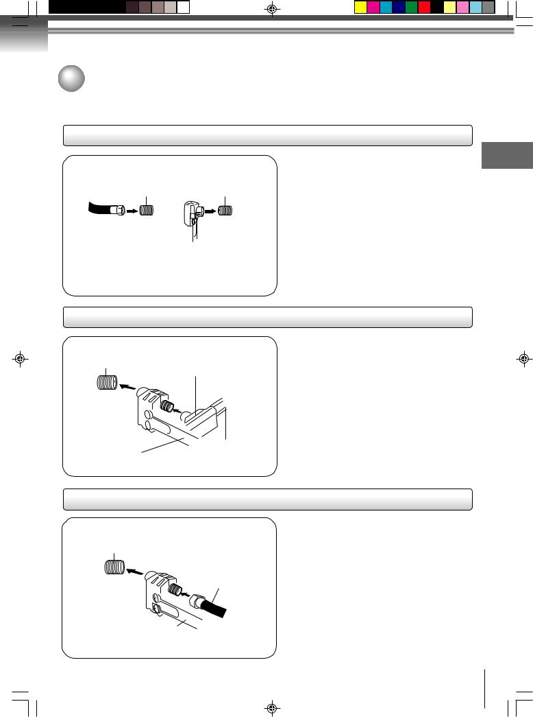
If you are using an indoor or outdoor antenna, follow the instructions below that correspond to your antenna system. If you are using a cable TV service (CABLE), see page 14 for Cable TV connections.
Combination VHF/UHF antenna (Single 75 ohm cable or 300 ohm twin-lead wire)
Antenna |
Antenna |
jack |
jack |
75 ohm coaxial cable (not supplied)
300-75 ohm matching transformer (supplied)
Connect the 75 ohm cable from the combination VHF/UHF antenna to the antenna jack.
If your combination VHF/UHF antenna has a 300 ohm twin-lead wire, the use of the 300-75 ohm matching transformer may be necessary.
Connections
Combination VHF/UHF antenna (Separate VHF and UHF 300 ohm twin-lead wires)
Antenna
jack
Combiner 
 (not supplied)
UHF 300 ohm twin-lead wire
(not supplied)
300-75 ohm matching transformer (supplied)
VHF 300 ohm twin-lead wire (not supplied)
Connect the UHF 300 ohm twin-lead wire to the combiner (not supplied). Connect the VHF 300 ohm twin-lead wire to the 300-75 ohm matching transformer. Attach the transformer to the combiner, then attach the combiner to the antenna jack.
Separate VHF/UHF antennas (75 ohm VHF cable and 300 ohm UHF twin-lead wires)
Antenna
jack
VHF 75 ohm
(not supplied)
Combiner 
 (not supplied)
UHF 300 ohm twin-lead wire
(not supplied)
Connect the VHF 75 ohm cable and UHF 300 ohm twin-lead wire to the combiner (not supplied). Attach the combiner to the antenna jack.
13
5S10101A [E] (P13-23) |
13 |
2/5/05, 9:41 AM |
Connections
Cable TV connections
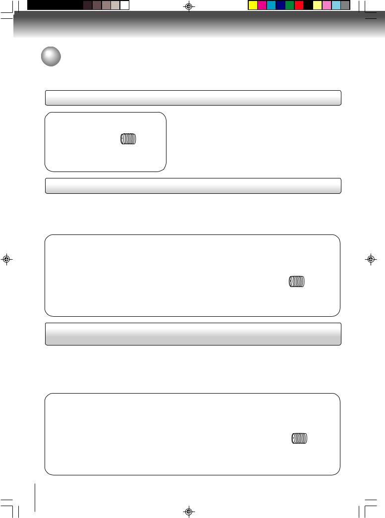
This TV/DVD has an extended tuning range and can tune most cable channels without using a Cable TV converter box. Some cable companies offer “premium pay channels” in which the signal is scrambled. Descrambling these signals for normal viewing requires the use of a descrambler device which is generally provided by the cable company.
For subscribers to basic cable TV service
Antenna
jack
75 ohm coaxial cable
For basic cable service not requiring a converter/descrambler box, connect the Cable TV 75 ohm coaxial cable directly to the Antenna jack on the back of the TV/DVD.
For subscribers to scrambled cable TV service
If you subscribe to a cable TV service which requires the use of a converter/descrambler box, connect the incoming 75 ohm coaxial cable to the converter/descrambler box. Using another 75 ohm coaxial cable, connect the output jack of the converter/descrambler box to the antenna jack on the TV/DVD. Follow the connections shown below. Set the TV/DVD to the output channel of the converter/descrambler box (usually channel 3 or 4) and use the converter/descrambler box to select channels.
Incoming |
|
Antenna |
|
75 ohm |
75 ohm cable |
||
jack |
|||
Cable TV |
to TV/DVD |
||
|
|||
|
Converter/ |
|
|
|
descrambler |
|
For subscribers to unscrambled basic cable TV service with scrambled premium channels
If you subscribe to a cable TV service in which basic channels are unscrambled and premium channels require the use of a converter/descrambler box, you may wish to use a signal splitter and an A/B Switch box (available from the cable company or an electronics supply store). Follow the connections shown below. With the switch in the “B” position, you can directly tune any nonscrambled channels on your TV/DVD. With the switch in the “A” position, tune your TV/DVD to the output of the converter/descrambler box (usually channel 3 or 4) and use the converter/ descrambler box to tune scrambled channels.
Incoming |
Converter/ |
|
|
|
descrambler |
|
Antenna |
||
75 ohm |
75 ohm cable |
|||
|
||||
|
jack |
|||
Cable TV |
|
to TV/DVD |
||
|
|
|||
Splitter |
A/B switch |
A |
|
|
|
|
B |
|
14
5S10101A [E] (P13-23) |
14 |
2/5/05, 9:41 AM |
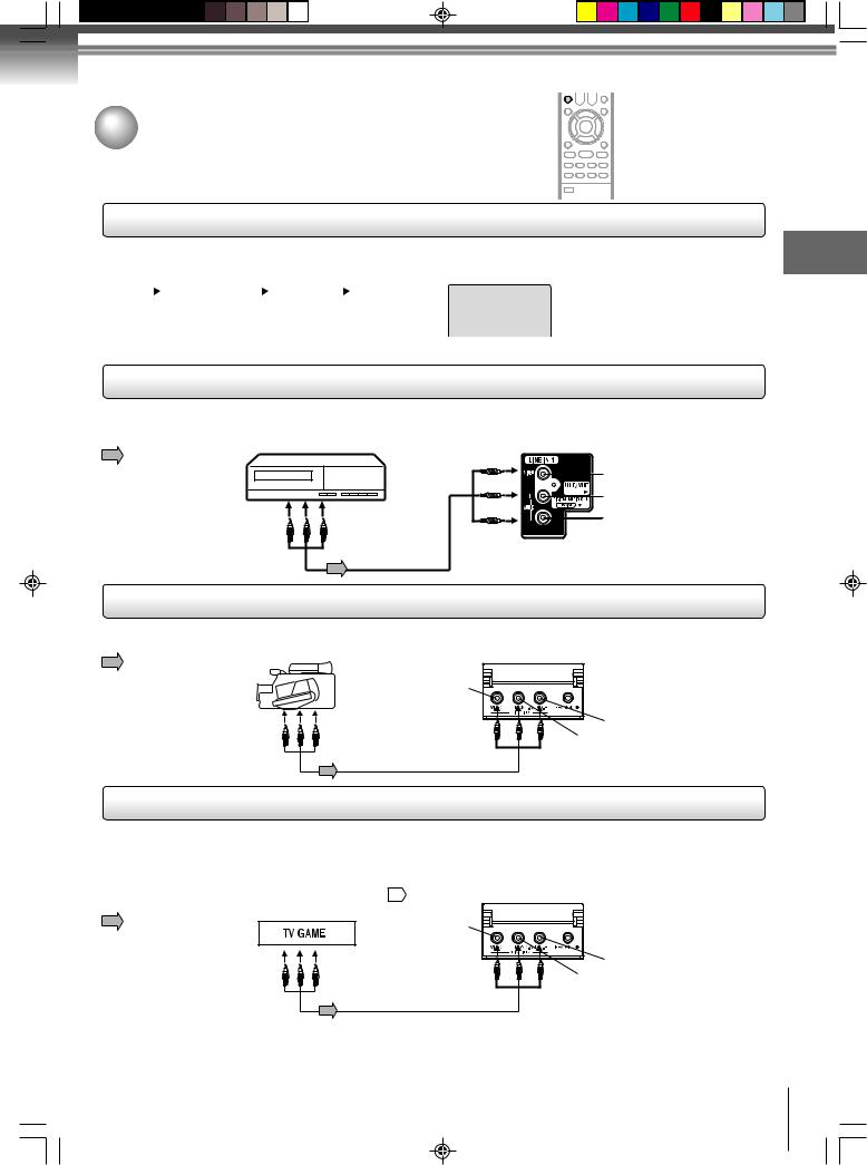
Connecting to optional equipment
You can enjoy VCR, camcorder or TV game with connection to external input. To select the external input, press INPUT and select “LINE1” or “LINE2” mode.
Using the audio/video inputs
Press INPUT repeatedly to select the desired mode.
“LINE1”, “LINE2” or TV channel will display on the screen for 4 seconds.
|
TV Channel |
|
LINE 1 |
|
LINE 2 |
|
|
|
|
|
(Back) |
|
(Front) |
|
|
|
|
|
|
|
|
|
|
Note: In the DVD mode this key will not operate.
 INPUT
INPUT


 GAME
GAME
Connections
To connect the TV/DVD to a VCR
Press INPUT to select the desired mode to use the TV as a monitor. |
|
Operate your VCR as usual. |
Rear of TV/DVD |
VCR |
|
: Signal flow |
|
|
VIDEO IN |
|
AUDIO IN (L) |
To Audio/Video OUT |
AUDIO IN (R) |
|
Audio/Video cable
(not supplied)
Illustration of MD24F51
To connect the TV/DVD to a camcorder
To playback from the camcorder, connect the camcorder to the TV/DVD as shown.
: Signal flow |
Camcorder |
Front of TV/DVD |
|
||
|
VIDEO IN |
|
|
To Audio/Video OUT |
AUDIO IN (R) |
|
|
AUDIO IN (L) |
Audio/Video cable (not supplied)
Illustration of MD24F51
To connect the TV/DVD to a TV Game
You can enjoy playing a TV game on the screen by adjusting to suitable brightness for your eyes.
1.Connect a TV Game to the TV/DVD.
2.Press GAME. The GAME mode screen appears.
• This TV/DVD has the GAME mode function 21 . |
Front of TV/DVD |
|
|
||
: Signal flow |
VIDEO IN |
|
|
|
|
|
To Audio/Video OUT |
AUDIO IN (R) |
|
|
|
|
|
AUDIO IN (L) |
Audio/Video cable (not supplied)
Illustration of MD24F51
Notes:
• You can also change the TV screen to LINE1 or LINE2 by pressing the CH  /
/ buttons.
•The TV/DVD can also be used as a display device for many video games. However, due to the wide variety of different types of signal generated by these devices and subsequent hook-up variations required, they have not all been included in the suggested connection diagrams. You'll need to consult each component's Owner's Manual for additional information.
15
5S10101A [E] (P13-23) |
15 |
2/5/05, 9:41 AM |
Connections
Connecting to optional equipment (Continued)
You can enjoy high quality dynamic sounds by connecting the * This section uses the following reference mark.
TV/DVD to optional audio equipment. |
|
||
|
|
: Front speaker |
: Center speaker |
|
|
: Rear speaker |
: Signal flow |
|
|
||
|
|
: Sub woofer |
|
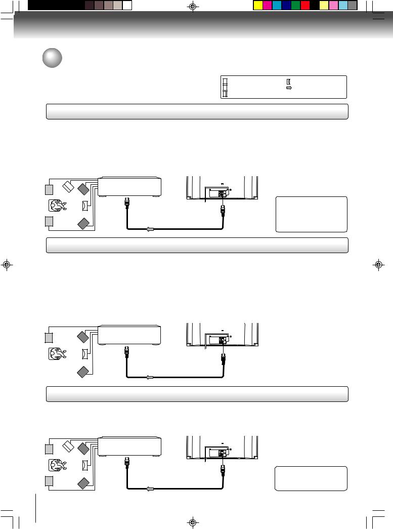
Connecting to an amplifier equipped with a Dolby Digital decoder
Dolby Digital
Dolby Digital is the surround sound technology used in theaters showing the latest movies, and is now available to reproduce this realistic effect in the home. You can enjoy motion picture and live concert DVD video discs encoded via the Dolby Digital recording system with this dynamic realistic sound by connecting the TV/DVD to a 6 channel amplifier equipped with a Dolby Digital decoder or Dolby Digital processor. If you have a Dolby Surround Pro Logic decoder, you will obtain the full benefit of Pro Logic from the same DVD movies that provide full 5.1-channel Dolby Digital soundtracks, as well as from titles with the Dolby Surround mark.
Illustration of MD24F51
Amplifier equipped with a
Dolby Digital decoder
To COAXIAL |
|
type digital |
|
audio input |
75 Ω coaxial cable (not supplied) |
•Use DVD video discs encoded via the Dolby Digital recording system.
Manufactured under license from Dolby Laboratories. “Dolby”, “Pro Logic”, and the double-D symbol are registered trademarks of Dolby Laboratories.
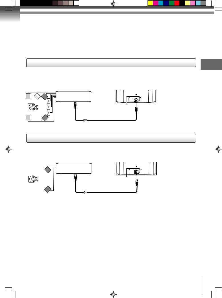
Connecting to an amplifier equipped with Dolby Surround Pro Logic
Dolby Surround Pro Logic
You can enjoy the dynamic realistic sound of Dolby Surround Pro Logic by connecting an amplifier and speaker system (right and left front speakers, a center speaker, and one or two rear speakers).
3With an amplifier equipped with Dolby Digital
Connect the equipment the same way as described in “Connecting to an amplifier equipped with a Dolby Digital decoder.” Refer to that amplifier’s owner’s manual and set the amplifier so you can enjoy Dolby Surround Pro Logic sound.
3With an amplifier not equipped with Dolby Digital
Connect the equipment as follows.
• This connection is only suitable for Video CDs and Audio CDs.
* |
Amplifier equipped with |
|
|
Dolby Surround Pro Logic |
|
|
To COAXIAL |
|
|
type digital |
75 Ω coaxial cable (not supplied) |
|
audio input |
|
Illustration of MD24F51
* Connect one or two rear speakers. The output sound from the rear speakers will be monaural even if you connect two rear speakers.
Connecting to an amplifier equipped with a DTS decoder
Digital Theater Systems (DTS)
DTS is a high quality surround technology used in theaters and now available for home use, on DVD video discs or audio CDs. If you have a DTS decoder or processor, you can obtain the full benefit of 5.1 channel DTS encoded sound tracks on DVD video discs or audio CDs.
Amplifier equipped with a DTS decoder
To COAXIAL type digital
audio input 75 Ω coaxial cable (not supplied)
•Use DVD video discs encoded via the Dolby
Digital recording system.
“DTS” and “DTS Digital Out” are registered trademarks of Digital Theater Systems, Inc.
16
5S10101A [E] (P13-23) |
16 |
2/5/05, 9:41 AM |
Connecting to an amplifier equipped with an MPEG2 audio decoder
MPEG2 sound
You can enjoy motion picture and live concert DVD video discs encoded via the MPEG2 recording system with dynamic realistic sound by connecting an amplifier equipped with an MPEG2 audio decoder or MPEG2 audio processor.
Illustration of MD24F51
Amplifier equipped with an
MPEG2 audio decoder
To COAXIAL |
|
• Use DVD video discs |
|
type digital |
|
||
75 Ω coaxial cable (not supplied) |
encoded via the Dolby |
||
audio input |
|||
|
|
Digital recording system. |
Connections
Connecting to an amplifier equipped with a digital audio input
2 channel digital stereo
You can enjoy the dynamic sound of 2 channel digital stereo by connecting an amplifier equipped with a digital audio input and speaker system (right and left front speakers).
Illustration of MD24F51
Amplifier equipped with a
Digital audio input
To COAXIAL |
|
type digital |
75 Ω coaxial cable (not supplied) |
audio input |
Notes:
•DO NOT connect the COAXIAL DIGITAL AUDIO OUT jack of the TV/DVD to the AC-3 RF input of a Dolby Digital Receiver. This input on your A/V Receiver is reserved for Laserdisc use only and is incompatible with the COAXIAL DIGITAL AUDIO
OUT jack of the TV/DVD.
•Connect the COAXIAL DIGITAL AUDIO OUT jack of the TV/DVD to the “COAXIAL” input of a Receiver or Processor.
•Refer to the owner’s manual of the connected equipment as well.
•When you connect the TV/DVD to other equipment, be sure to turn off the power and unplug all of the equipment from the wall outlet before making any connections.
•The output sound of the TV/DVD has a wide dynamic range. Be sure to adjust the receiver’s volume to a moderate listening level. Otherwise, the speakers and your hearing may be damaged by a sudden high volume sound.
•Turn off the amplifier before you connect or disconnect the TV/DVD’s power cord. If you leave the amplifier power on, the speakers may be damaged.
17
5S10101A [E] (P13-23) |
17 |
2/5/05, 9:42 AM |
 Loading...