

Page 1

Memory Module Replacement Guide
TOSHIBA
Memory Module Replacement Guide
Table of Contents
Preface . . . . . . . . . . . . . . . . . . . . . . . . . . . . . . . . . . . . . . . . . . . . . . . . . . . iii
Chapter1 Introduction. . . . . . . . . . . . . . . . . . . . . . . . . . . . . . . . . . . . . . 1-1
Chapter2 Before you start the replacement . . . . . . . . . . . . . . . . . . . . 2-1
Chapter3 Replacing the memory module . . . . . . . . . . . . . . . . . . . . . . 3-1
Chapter4 After you have done the replacement. . . . . . . . . . . . . . . . . 4-1
Page 2

ii User’s Manual
Copyright
© 2004 by TOSHIBA Corporation. All rights reserved. Under the copyright
laws, this manual cannot be reproduced in any form without the prior
written permission of TOSHIBA. No patent liability is assumed, with respect
to the use of the information contained herein.
TOSHIBA Memory module Replacement Guide
First edition September 2004
Trademarks
Windows and Microsoft are registered trademarks of Microsoft Corporation.
Other trademarks and registered trademarks not listed above may be used
in this manual.
Page 3

User’s Manual iii
Memory Module Replacement Guide
Preface
This guide contains information on how to replace a memory module for
TOSHIBA personal computers.
When the Diagnostic Tool indicates that a memory module should be
replaced, first check the model of your computer, and then follow the
instructions in this guide for replacing it.
This guide covers the following models:
Conventions
This manual uses the following formats to describe, identify, and highlight
terms and operating procedures.
Abbreviations
On first appearance, and whenever necessary for clarity, abbreviations are
enclosed in parentheses following their definition. For example: Read Only
Memory (ROM). Acronyms are also defined in the Glossary.
Messages
Messages are used in this manual to bring important information to your
attention. Each type of message is identified as shown below.
■ TECRA S1
■ TECRA 9100
■ TECRA M1
■ TECRA M2
■ Satellite 2400
■ Satellite 2405
■ Satellite 1110/1115
■ Satellite Pro M10
■ Satellite Pro M15
■ Satellite M30/M35
■ Portégé R100
■ Portégé M200/M205
Pay attention! A caution informs you that improper use of equipment or
failure to follow instructions may cause data loss or damage your
equipment.
Please read. A note is a hint or advice that helps you make best use of
your equipment.
Page 4

iv User’s Manual
Preface
Page 5

User’s Manual 1-1
Memory Module Replacement Guide
Chapter 1
Introduction
This chapter provides a basic outline of the steps for replacing a memory
module.
Refer to the associated chapter or section for detailed information.
1. Chapter 2 Before you start the replacement
This chapter describes the preparatory tasks on the components such as
the AC adapter and the battery pack before you begin the replacement
procedure.
2. Chapter 3 Replacing the memory module
This chapter explains how to replace the memory module for each of the
models.
3. Chapter 4 After the replacement
This chapter describes how to check whether the new memory module is
installed correctly.
Page 6

1-2 User’s Manual
Introduction
Page 7

User’s Manual 2-1
Memory Module Replacement Guide
Chapter 2
Before you start the replacement
Be sure to read the User’s Guide provided with your computer and then
perform the following steps.
1. Turn the computer’s power off. Be sure the computer is not in sleep,
suspend, or hibernate mode. Make sure the Power indicator is off.
2. Remove AC adapter and all cables and devices connected to the
computer.
3. Turn the computer upside down and remove the battery pack. Refer to
the instructions for removing the battery pack in the User’s Guide for
your computer.
When you have completed the steps above, proceed to Chapter 3:
Replacing the memory module.
■ Do not try to install or remove a memory module unless you have
completed steps 1 through 3 above. You can damage the computer
and the memory module and you may lose data.
■ Only install the memory module in the computer for which it was
intended. If the memory is incorrectly installed, or installed in the wrong
computer, the computer will issue a series of short beeps. If this occurs,
shut down the power and remove the memory module.
■ Be careful not to let screws or other foreign objects fall into the
computer. It may cause damage or injury.
Use a size 0 Phillips screwdriver to remove and secure screws. Use of an
incorrect screwdriver can damage the screw heads.
Page 8

2-2 User’s Manual
Before you start the replacement
Page 9

User’s Manual 3-1
Memory Module Replacement Guide
Chapter 3
Replacing the memory module
This chapter explains how to replace the memory module(s).
1. Removing the memory module cover
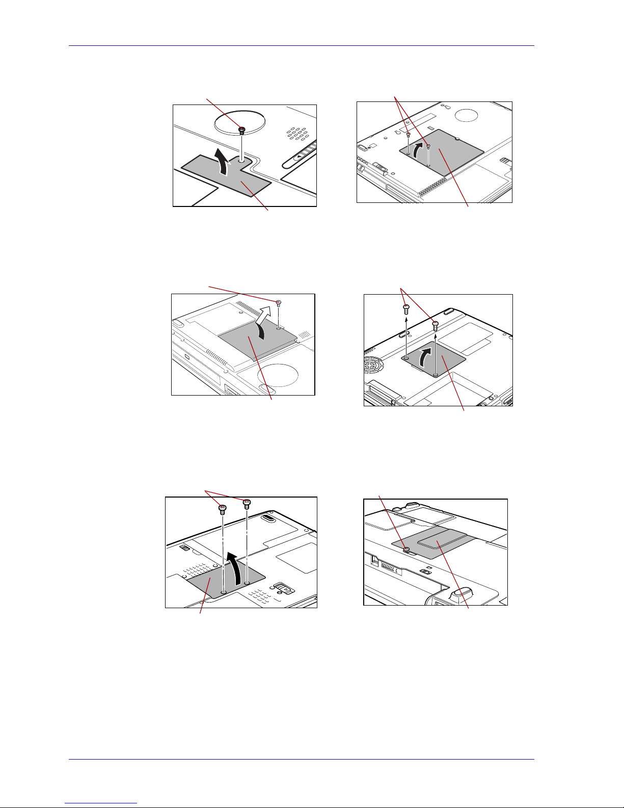
1. Remove or loosen the screws securing the memory module cover.
2. Lift off the cover.
For the following models:
■ The replacement procedure depends on the model of the computer.
Check your model and refer to the instructions for that model.
■ Most computers have two memory slots. Be sure to remove the
affected memory module(s) before installing the replacement(s). The
illustrations below may only show one memory module being replaced.
If both modules are affected, the procedure must be repeated for each
affected module.
Use a size 0 Phillips screwdriver.
■ TECRA S1
■ TECRA 9100
■ TECRA M1
■ TECRA M2
■ Satellite 2400
■ Satellite 2405
■ Satellite 1110/1115
■ Satellite Pro M10
■ Satellite Pro M15
■ Satellite M30/M35
■ Portégé R100
■ Portégé M200/M205
■ Do not touch the connectors on the memory module or on the
computer. Contamination on the connectors may cause memory
failures.
■ Do not leave foreign objects or dropped screws in the computer.
Page 10
3-2 User’s Manual
Replacing the memory module
TECRA S1 TECRA 9100
Removing one screw Removing two screws
Satellite 2400/2405 Satellite 1110/1115
Removing one screw Removing two screws
Satellite Pro M10/M15 Satellite M30/M35
Removing two screws Loosen one screw
Screw
Memory module
cover
Screws
Memory module
cover
Screw
Memory module
cover
Screws
Memory module
cover
Screws
Memory module
cover
Screw
Memory module
cover
Page 11
User’s Manual 3-3
Replacing the memory module
TECRA M1
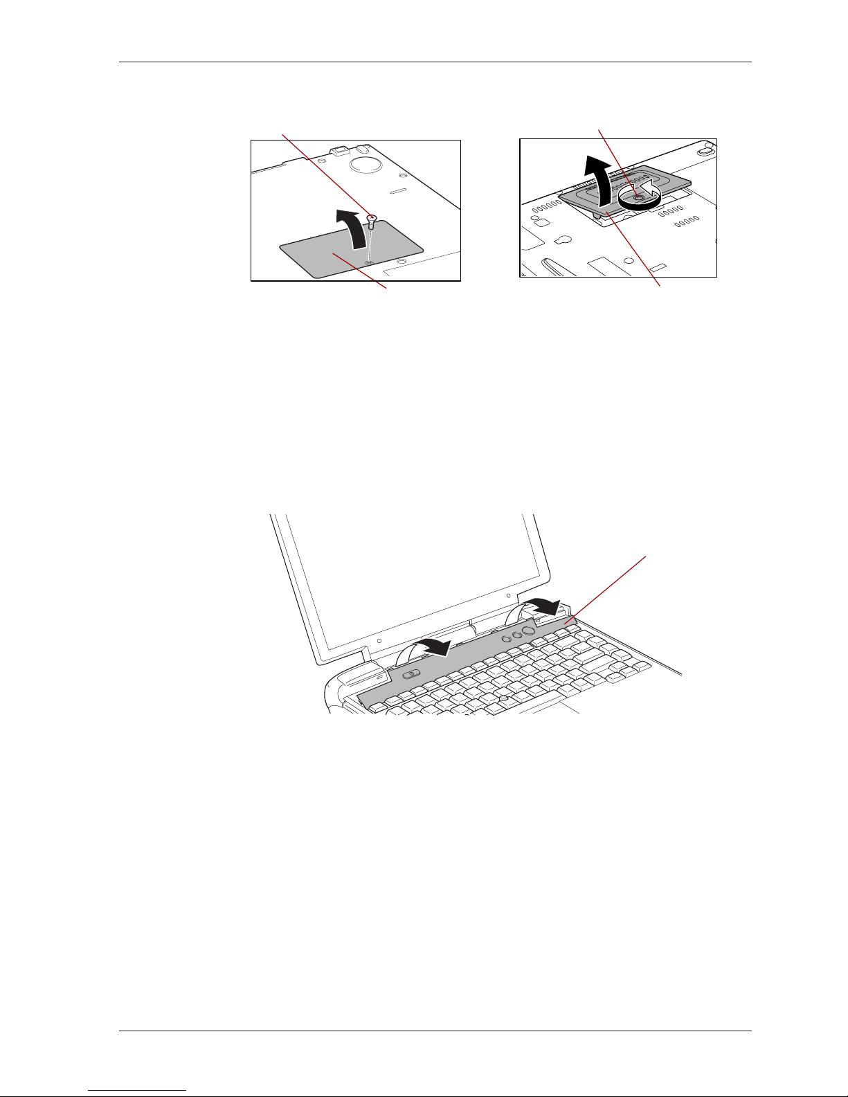
1. Turn the computer to the normal position and open the display panel.
Tilt the display panel slightly beyond the upright position before
removing the keyboard brace as shown in the illustration below.
2. Put your fingers on both ends of the keyboard brace and remove it
carefully in the direction indicated by the arrows in the illustration below.
Removing the keyboard brace
Portégé R100 Portégé M200/M205
Removing one screw Loosen one screw
Screw
Memory module
cover
Screw
Memory module
cover
Keyboard brace
Page 12
3-4 User’s Manual
Replacing the memory module
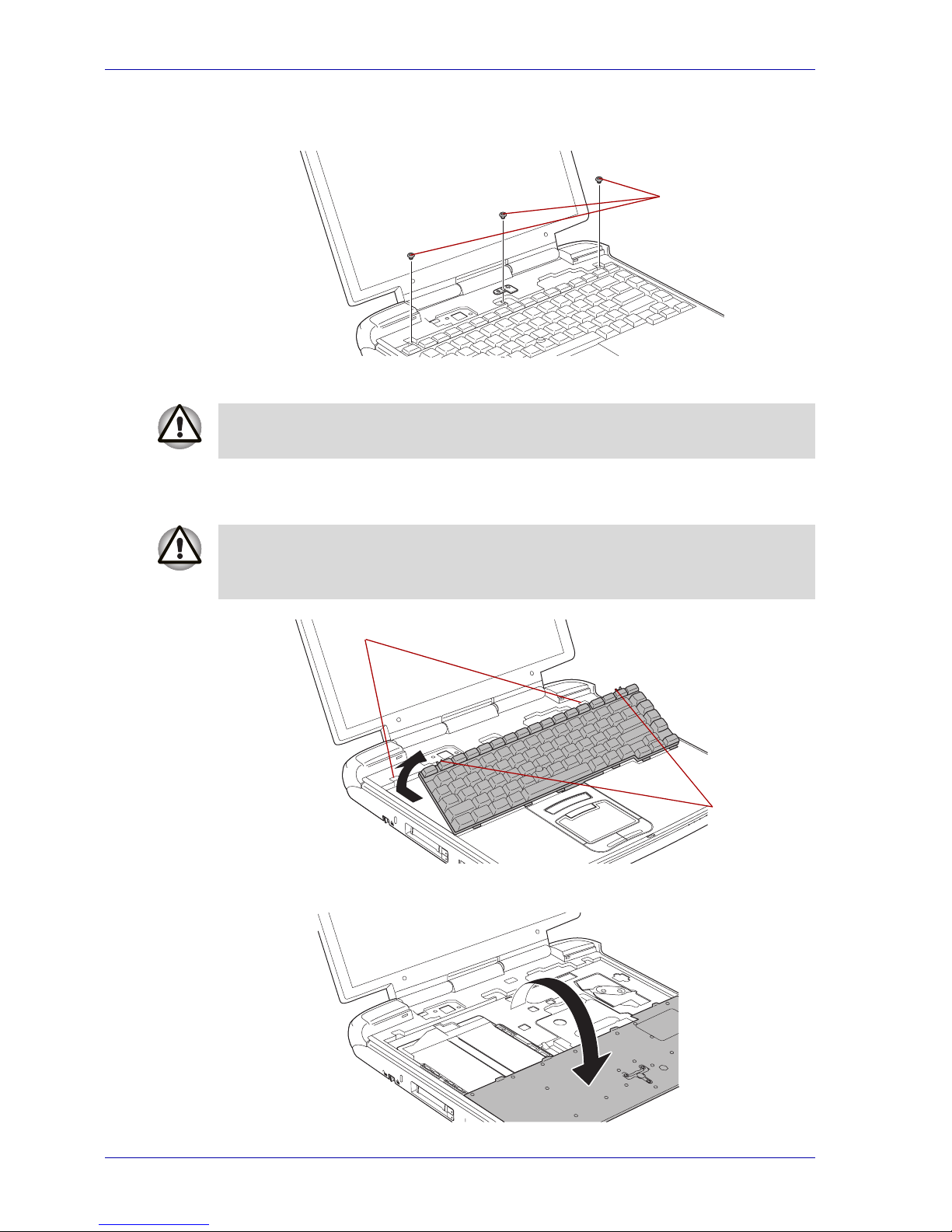
3. Remove three screws (left, center, and right) as shown in the illustration
below.
Removing the keyboard (1)
4. Lift the back of the keyboard toward you and lay it face down on the
palmrest as shown in the illustrations below.
Removing the keyboard (2)
Screws
Be careful not to drop the screws inside the computer when removing the
keyboard.
The keyboard is connected to the computer by a ribbon cable. Be careful
not to apply tension to this cable when you lift the keyboard. Do not
disconnect this cable.
Ta bs
Slits
Page 13
User’s Manual 3-5
Replacing the memory module
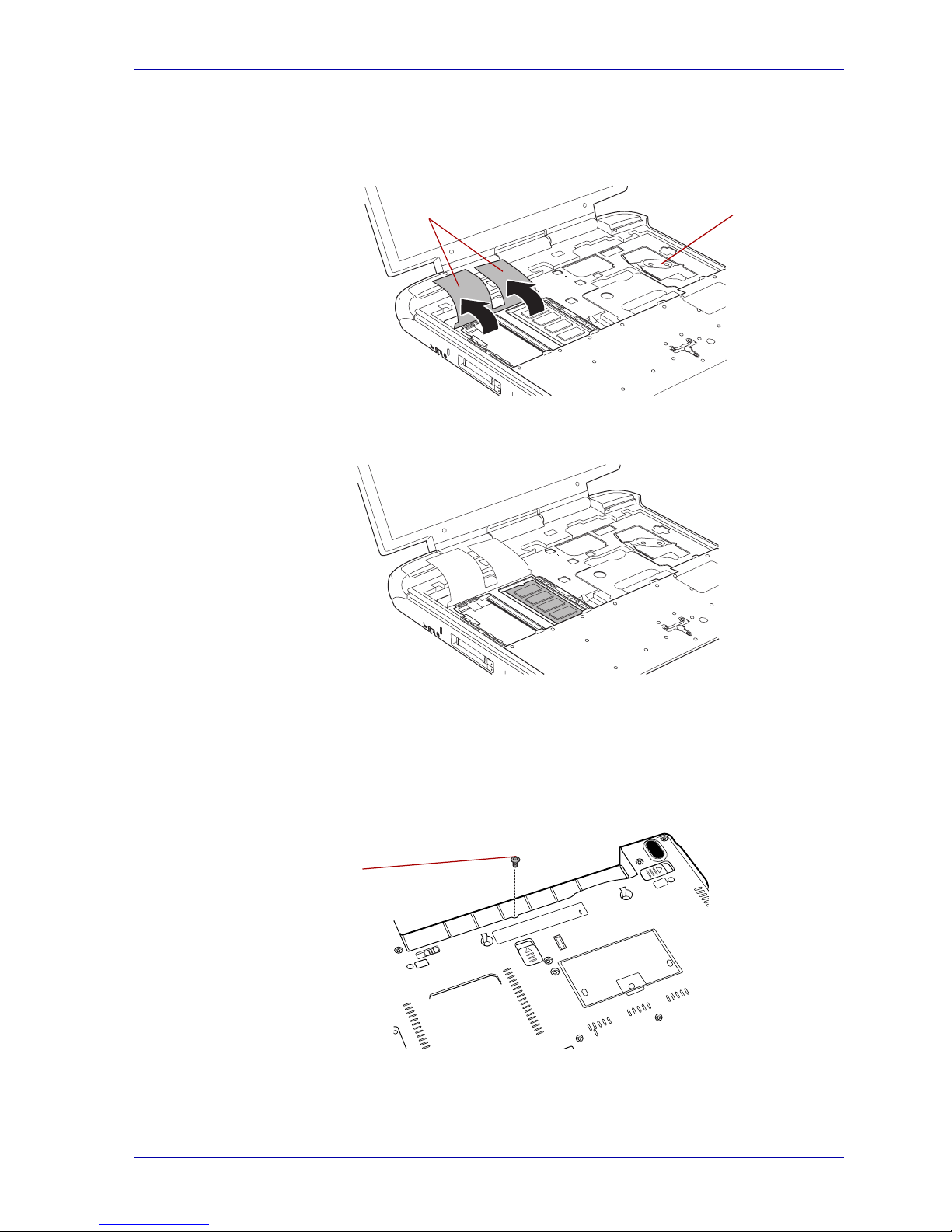
Removing the keyboard (3)
5. Lift the insulation sheet(s) covering the memory module(s) to expose
the memory module(s).
Lifting the insulation sheets
6. Secure the insulation sheet(s) temporarily with masking tape.
Lifting the insulation sheets
TECRA M2
■ Main memory module
1. Remove the battery from the computer. Remove one screw from the
battery compartment as shown in the illustration below.
Removing one screw.
2. Open the display panel.
3. Insert a thin object under the rim of the keyboard brace and lift it out.
Insulation
sheets
VGA chip
Screw
Page 14
3-6 User’s Manual
Replacing the memory module
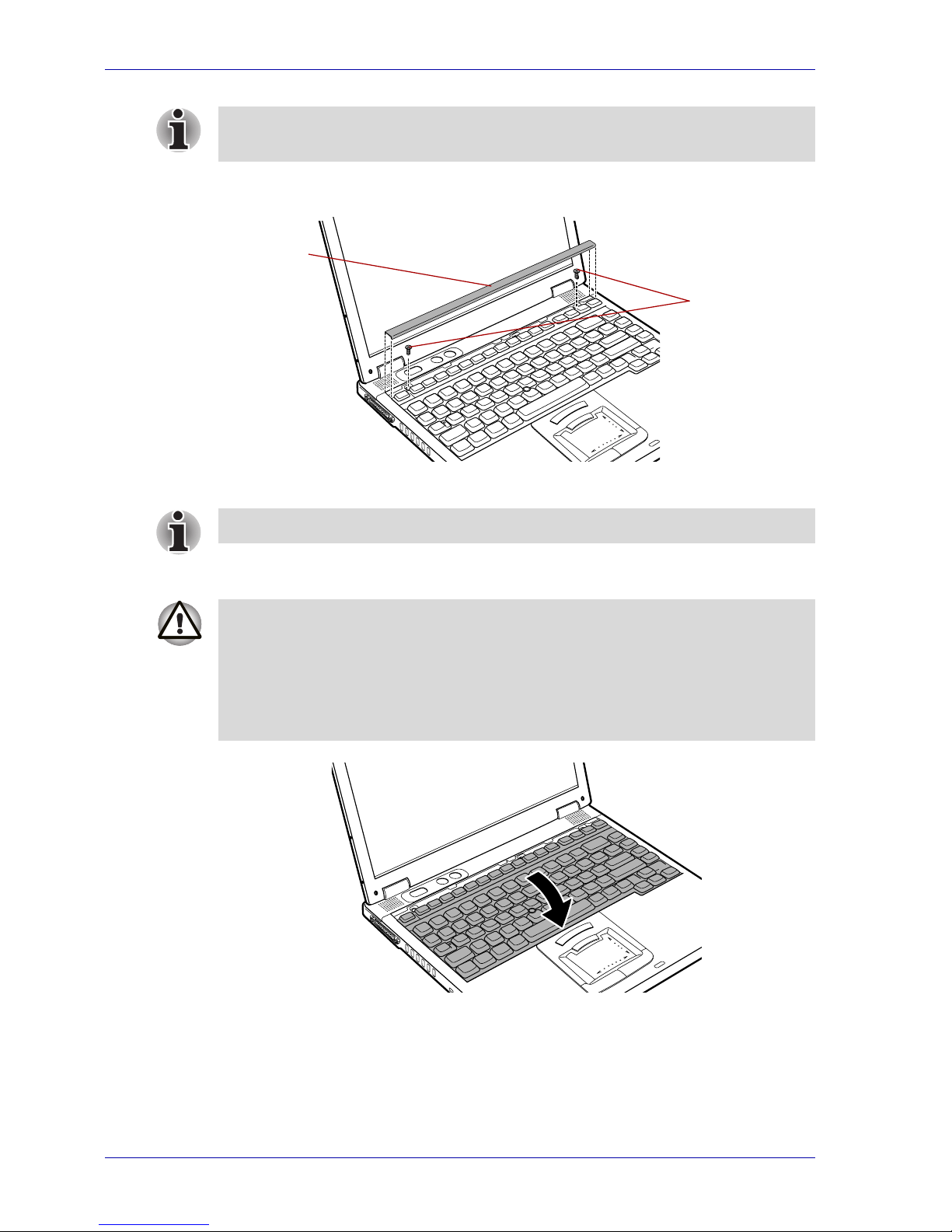
4. Remove two screws securing the keyboard as shown in the illustration
below.
Removing the keyboard brace and two screws
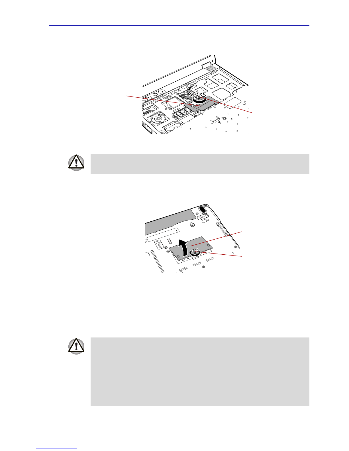
5. Lift the back of the keyboard toward you and lay it face down on the
palmrest as shown in the illustration below.
Lift the keyboard
Only remove the keyboard brace after completing steps 1-3. Otherwise,
you may damage the keyboard brace.
Keyboard
brace
Screws
Use a size 0 Phillips screwdriver.
■ When you move the keyboard forward, do not touch the keys. Doing so
could cause misalignment. Hold the keyboard by the sides and lay it
gently on the palmrest.
■ The keyboard is connected to the computer by a ribbon cable. Be
careful not to apply tension to this cable when you lift the keyboard. Do
not disconnect this cable.
Page 15
User’s Manual 3-7
Replacing the memory module
6. Remove the screw securing the metal bracket. Remove the bracket as
shown in the illustration below.
Removing the metal bracket
■ Secondary memory module
1. Loosen, but do not remove, the screw on the memory module cover.
Removing the memory module cover
2. Removing the memory module
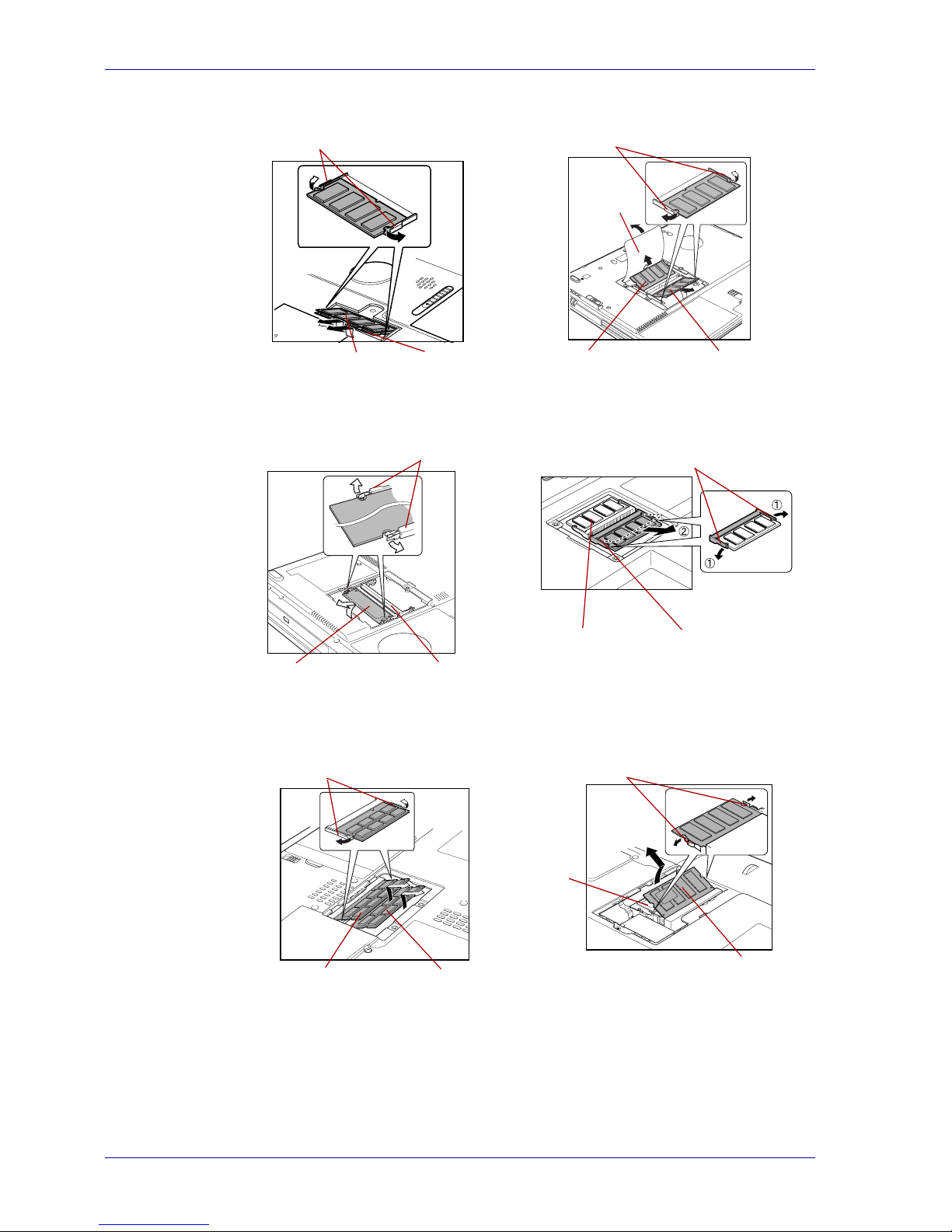
1. Press the latches to the outside to release the module. A spring will
push one end of the module up.
2. Hold the module by the edges and pull it out.
Metal bracket
Screw
Do not touch the connectors on the memory module or on the computer.
Contamination on the connectors may cause memory failures.
Screw
Memory module
cover
■ If you use the computer for a long time, the memory modules and the
circuits close to the memory modules will become hot. Be sure to let
them cool to room temperature before you replace the memory
modules.
■ Do not touch the connectors on the memory module or on the
computer. Contamination on the connectors may cause memory
failures.
■ Do not leave foreign objects or dropped screws in the computer.
Page 16
3-8 User’s Manual
Replacing the memory module
TECRA S1 TECRA 9100
Satellite 2400/2405 Satellite 1110/1115
Satellite Pro M10/M15 Satellite M30/M35
Latches
Slot A (Lower)
Slot B (Upper)
Latches
Slot A
Slot B
Shield
sheet
Latches
Slot B
Slot A
Latches
Slot BSlot A
Latches
Slot A (Lower)Slot B (Upper)
Latches
Slot A
(Lower)
Slot B (Upper)
Page 17
User’s Manual 3-9
Replacing the memory module
TECRA M1
1. Press the latches to the outside to release the module. A spring will
push one end of the module up.
2. Hold the module by the edges and pull it out.
Removing the memory module
Portégé R100 Portégé M200/M205
Slot A
Latches
Slot B (Upper)
Slot A (Lower)
■ If you use the computer for a long time, the memory modules and the
circuits close to the memory modules will become hot. Be sure to let
them cool to room temperature before you replace the memory
modules.
■ Do not touch the connectors on the memory module or on the
computer. Contamination on the connectors may cause memory
failures.
Slot A
Slot B
(Not shown)
Page 18
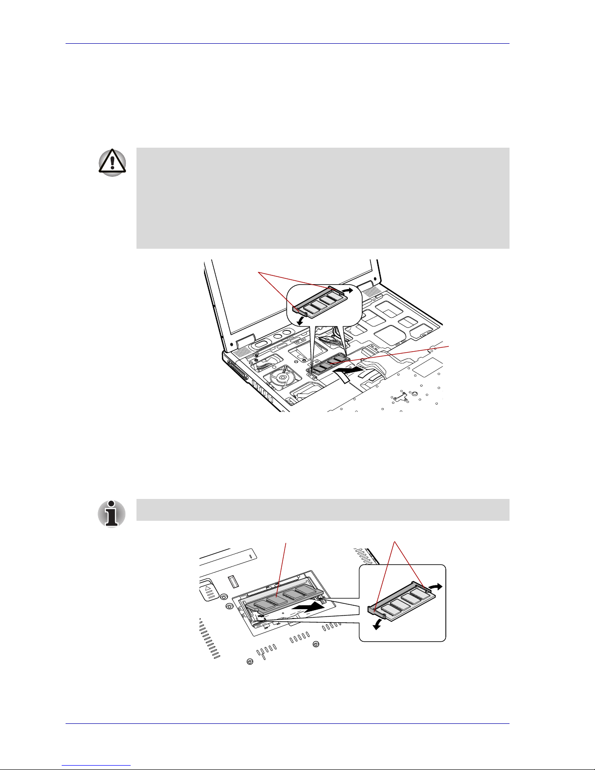
3-10 User’s Manual
Replacing the memory module
TECRA M2
■ Main memory module
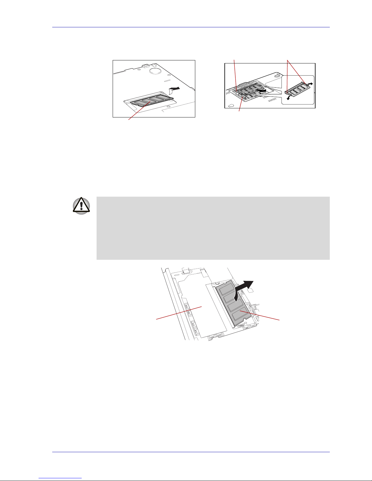
1. Press the latches to the outside to release the module. A spring will
push one end of the module up.
2. Hold the edges of the module and pull it out, then replace the insulator.
Removing the memory module
■ Secondary memory module
1. Press the latches to the outside to release the module. A spring will
push one end of the module up.
2. Hold the edges of the module and pull it out, then replace the insulator.
Removing the memory module
■ If you use the computer for a long time, the memory modules and the
circuits close to the memory modules will become hot. Be sure to let
them cool to room temperature before you replace the memory
modules.
■ Do not touch the connectors on the memory module or on the
computer. Contamination on the connectors may cause memory
failures.
Latches
Slot A
When the memory module pops up, you can remove it from the slot.
LatchesSlot B
Page 19
User’s Manual 3-11
Replacing the memory module
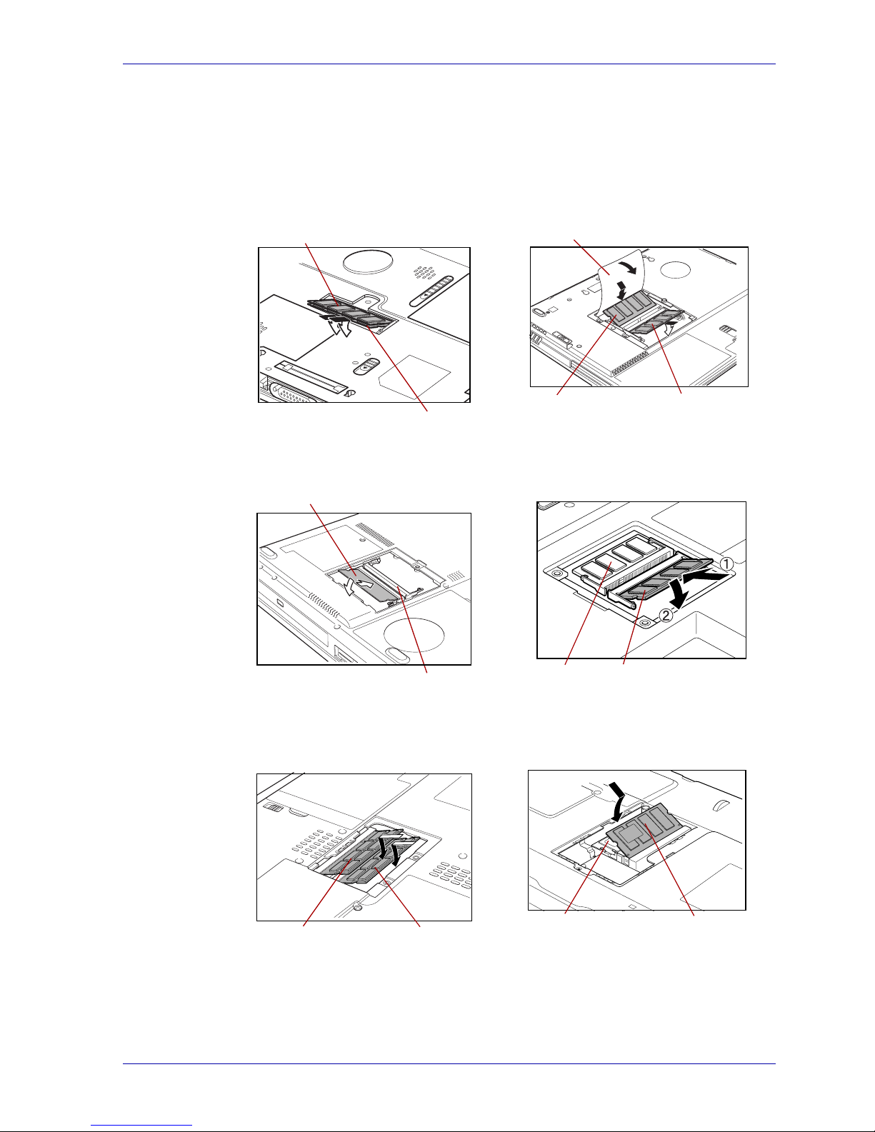
3. Insert/install memory module
1. Firmly push the memory module into the connector, matching the notch.
Press down on the memory module until the latches on either side click
into place.
TECRA S1 TECRA 9100
Satellite 2400/2405 Satellite 1110/1115
Satellite Pro M10/M15 Satellite M30/M35
Slot B (Upper)
Slot A (Lower)
Guide sheet
Slot A
Slot B
Slot A
Slot B
Slot A
Slot B
Slot A (Lower)Slot B (Upper)
Slot A
Slot B
Page 20
3-12 User’s Manual
Replacing the memory module
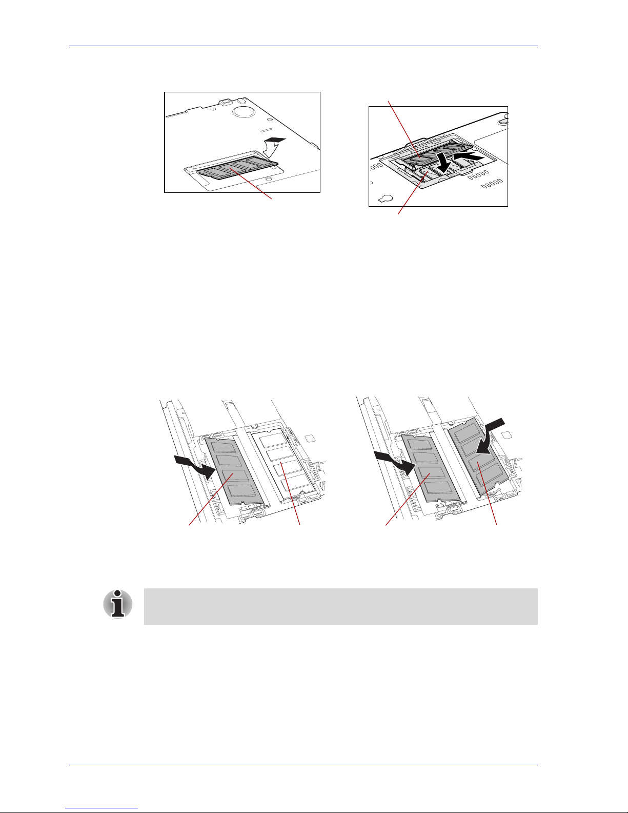
2. Seat the memory module cover and secure it with one screw.
3. Replace the battery pack as described in the User’s Guide for your
computer.
TECRA M1
1. Firmly push the memory module into the connector, matching the notch.
Press down on the memory module until the latches on either side click
into place.
2. Seat the insulation sheet to cover the module.
Portégé R100 Portégé M200/M205
Slot A
Slot A (Lower)
Slot B (Upper)
Installing a memory module Installing two memory modules
Slot ASlot B Slot ASlot B
Be sure to check that the insulation sheet is returned to the original
position to cover the memory module(s).
Page 21
User’s Manual 3-13
Replacing the memory module
3. Align the two tabs on the lower edge of the keyboard with the slits on
the computer and seat the keyboard in its original position. Refer to
Removing the keyboard (2). Replace the three screws removed in step
6 above.
4. Seat the keyboard brace in its original position.
5. Replace the battery pack as described in the User’s Guide for your
computer.
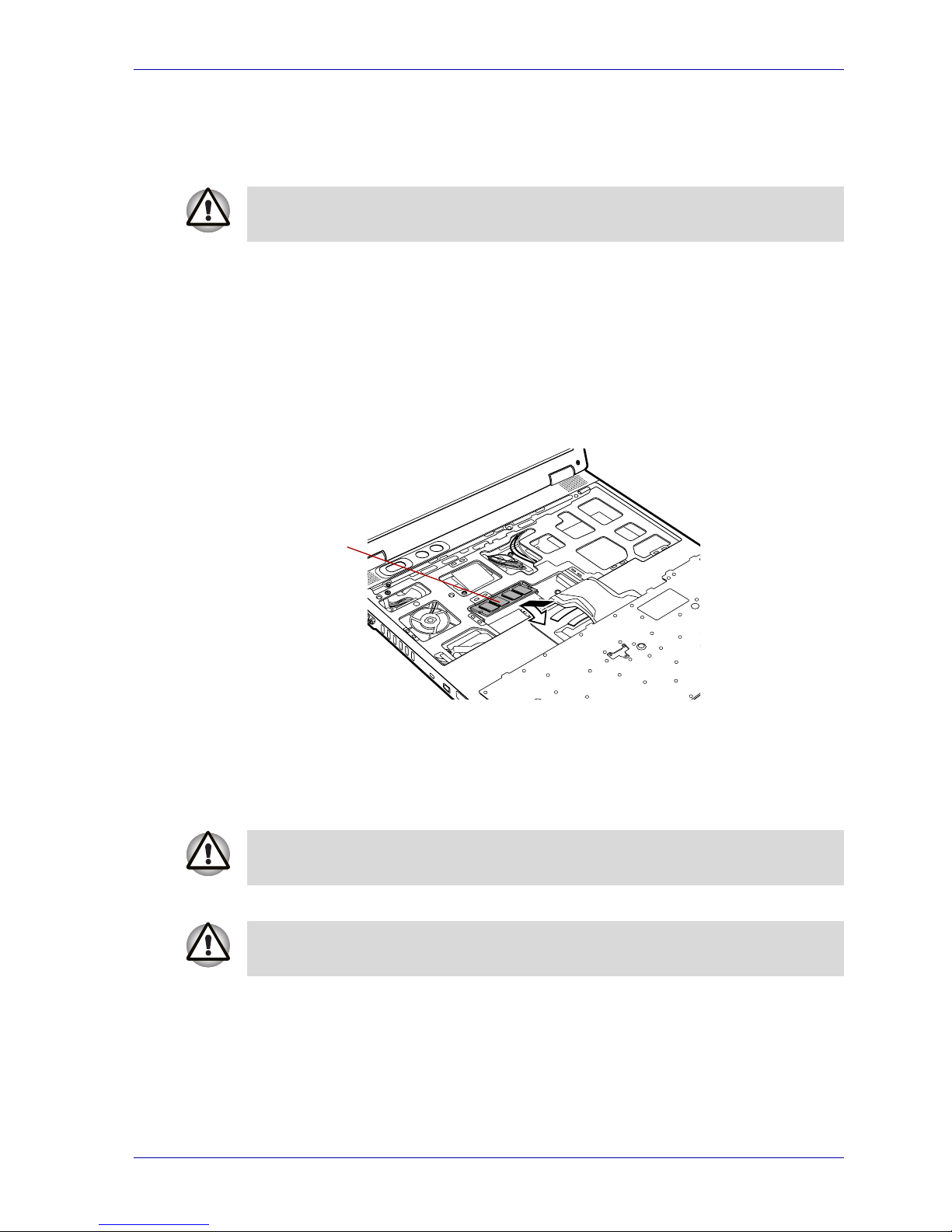
TECRA M2
■ Main memory module
1. Firmly push the new memory module into the socket and push it down
so it lies flat and is secured by two latches on either side.
Installing the memory module
2. Seat the metal bracket over the keyboard cable and secure it with one
screw.
3. Insert tabs on the front of the keyboard into corresponding notches on
the computer and seat the keyboard in its original position.
4. Replace the two screws to secure the keyboard.
5. Seat the keyboard brace and press to secure latches.
6. Replace the screw removed from the battery compartment.
7. Install the battery pack. Refer to replacing the battery pack section in
the User’s Guide for your computer.
Be sure to replace all screws that were removed in step 6. Do not leave
foreign objects, such as tape or dropped screws, in the computer.
Slot A
When seating the keyboard, be sure to fit the flexible cable under the
palmrest if it was pulled out while you were removing the keyboard.
Be sure to replace both screws removed in Removing the keyboard brace
and two screws. Make sure not to drop any screws into the computer.
Page 22
3-14 User’s Manual
Replacing the memory module
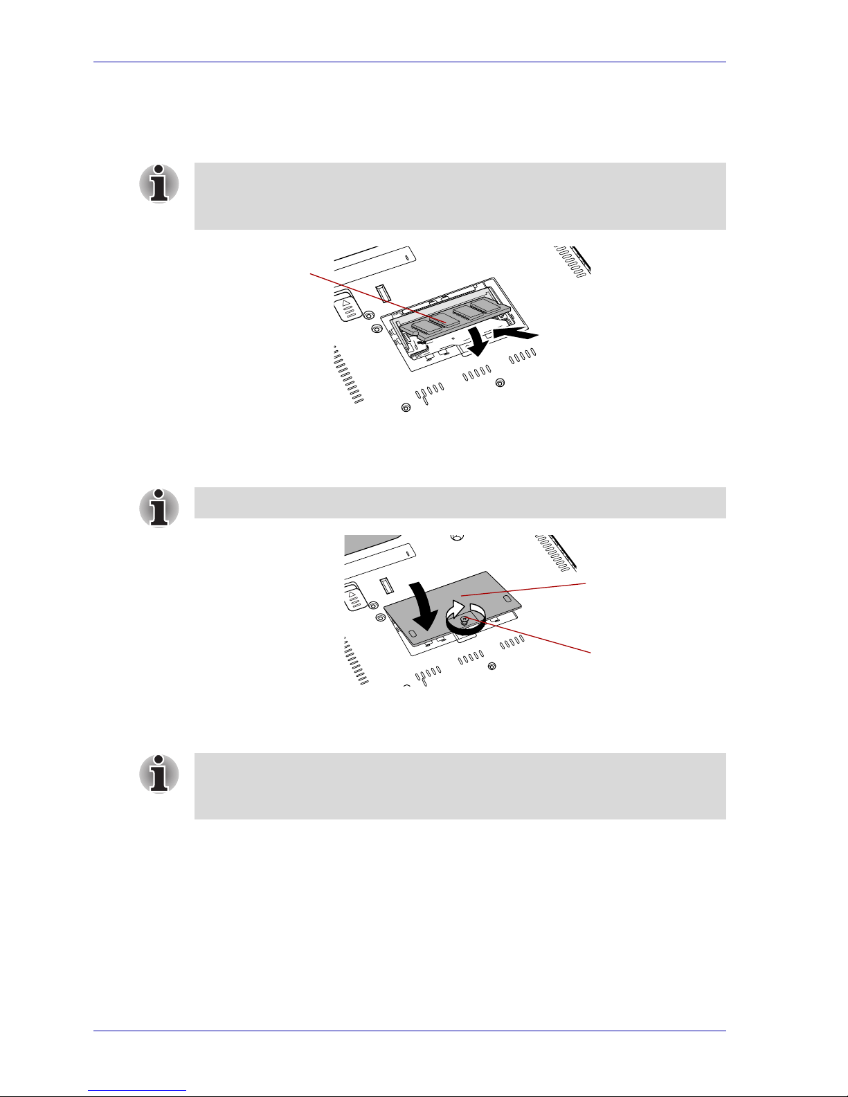
■ Secondary memory module
1. Firmly push the memory module into the connector of the memory
module slot. Press the memory module down until it is secured in place.
Installing the secondary memory module
2. Seat the memory module cover and secure the screw you loosened in
Removing the memory module cover.
Seating the memory module cover
3. Reinstall the battery pack, if not already done.
When you have completed the steps above, proceed to Chapter 4: After the
replacement.
Align the grooves of the memory module with the latches of the connector
and insert the module into the connector firmly. Make sure to hold the
memory module by the edges.
Slot B
Be sure that the memory cover is securely closed.
Screw
Memory module
cover
After installing a memory module, turn the computer on and check the total
memory size, see Chapter 4. The system will calculate the total memory
size.
Page 23

User’s Manual 4-1
Memory Module Replacement Guide
Chapter 4
After the replacement
This chapter explains the steps you need to complete after replacing the
memory module(s).
The total memory size can be confirmed in System Properties.
In addition, System Properties can confirm the version of the operating
system and the type of CPU.
Perform the following steps to verify that the total memory size is correct.
Microsoft® Windows
®
XP Home Edition or Windows
XP Professional
1. Open the Control Panel and click Performance and Maintenance.
2. Click Display basic information about your computer.
The System Properties dialog is displayed.
3. Make sure that the RAM size is correct in the General tab.
Microsoft Windows 2000, Windows 98 Second Edition
or Windows NT
®
4.0
1. Open the Control Panel and double-click System.
2. Make sure that the RAM size is correct in the General tab.
After you turn on your computer, the total memory size is automatically
calculated.
Page 24

4-2 User’s Manual
After the replacement
 Loading...