

IPR
Network Video Recorder
User Manual
model no.
IPR8-X
IPR16-X
Please carefully read these instructions before using this product.
Save this manual for future use.
1
Surveillix™ IPR
User Guide
Manual Edition 27810AF – NOVEMBER 2008
Printed in USA
No part of this documentation may be reproduced in any means, electronic or mechanical, for any purpose, except as expressed in the
Software License Agreement. Toshiba shall not be liable for technical or editorial errors or omissions contained herein. The information in
this document is subject to change without notice.
THE INFORMATION IN THIS PUBLICATION IS PROVIDED “AS IS” WITHOUT WARRANTY OF ANY KIND. THE ENTIRE RISK ARISING
OUT OF THE USE OF THIS INFORMATION REMAINS WITH RECIPIENT. IN NO EVENT SHALL TOSHIBA BE LIABLE FOR ANY
DIRECT, CONSEQUENTIAL, INCIDENTAL, SPECIAL, PUNITIVE, OR OTHER DAMAGES WHATSOEVER (INCLUDING WITHOUT
LIMITATION, DAMAGES FOR LOSS OF BUSINESS PROFITS, BUSINESS INTERRUPTION OR LOSS OF BUSINESS INFORMATION ),
EVEN IF TOSHIBA HAS BEEN ADVISED OF THE POSSIBILITY OF SUCH DAMAGES AND WHETHER IN AN ACTION OR CONTRACT
OR TORT, INCLUDING NEGLIGENCE.
This software and documentation are copyrighted. All other rights, including ownership of the software, are reserved to DVR Support Center.
TOSHIBA, and Surveillix are registered trademarks of TOSHIBA CORPORATION in the United States and elsewhere; Windows, and
Windows 2000 are registered trademarks of Microsoft Corporation. All other brand and product names are trademarks or registered
trademarks of the respective owners.
The following words and symbols mark special messages throughout this guide:
WARNING: Text set off in this manner indicates that failure to follow
directions could result in bodily harm or loss of life.
CAUTION: Text set off in this manner indicates that failure to follow
directions could result in damage to equipment or loss of information.
ii

LIMITED WARRANTY
NETWORK VIDEO RECORDER
The Imaging Systems Division of Toshiba America Information Systems, Inc. ("ISD") makes the following limi t ed warranties. These
limited warranties extend to the Original End-User ("You[r]").
Limited Two (2) Year Warranty of Labor and Parts
The Imaging Systems Division of Toshiba America Information Systems warrants this product and parts against defects in material or
workmanship for a period of two years from the date of original retail purchase by the end-user. During this period, ISD will repair or
replace a defective product or part with a new or refurbished item. The user must deliver the entire product to the Surveillix DVR Repair
Facility. The user is responsible for all transportation and insurance charges for the product to the DVR Repair Facility. ISD reserves the
right to substitute Factory Refurbished Parts and / or Factory Refurbished Product in place of those in need of repair.
Step-by-step Procedures - How to Obtain Warranty Service
[1] Verify operation of the unit by checking the instruction manual and web site for the latest updates at
www.toshiba.com/taisisd
[2] If there is a defect in material or workmanship, contact the Surveillix DVR Support Center at (877) 855-1349 [877-1- FIX] to speak to a
technical support representative and schedule service.
[3] Arrange for delivery of the product to the Surveillix DVR Repair Facility. Products must be insured and securely packed, preferably in the
original shipping carton. A letter explaining the defect and a copy of the bill of sale or other proof of purchase must be enclosed with a
complete return street address and daytime telephone number. The Tracking Number should also be indicated on your documents. Charges
for transportation and insurance must be prepaid by the end-user.
Critical Use Disclaimer
The product is not designed for any “critical applications.” “Critical applications” means life support systems, exhaust or smoke extraction
applications, medical applications, commercial aviation, mass transit applications, military applications, homeland security applications,
nuclear facilities or systems or any other applications where product failure could lead to injury to persons or loss of life or catastrophic
property damage. Accordingly, Toshiba disclaims any and all liability arising out of the use of the product in any critical applications.
Your Responsibilities
The above warranty is subject to the following conditions:
[1] You must retain the bill of sale or provide other proof of purchase.
[2] You must schedule service within thirty days after you discover a defective product or part.
[3] All warranty servicing of this product must be made by the Surveillix DVR Repair Facility.
[4] The warranty extends to defects in material or workmanship as limited above, and not to any products or parts that have been lost or
discarded by user. The warranty does not cover damage caused by misuse, accident, improper installation, improper maintenance, or use in
violation of instructions furnished by ISD. The warranty does not extend to units which have been altered or modified without authorization of
ISD, or to damage to products or parts thereof which have had the serial number removed, altered defaced or rendered illegible.
ALL WARRANTIES IMPLIED BY STATE LAW, INCLUDING THE IMPLIED WARRANTIES OF MERCHANTABILITY AND FITNESS FOR
A PARTICULAR PURPOSE, ARE EXPRESSLY LIMITED TO THE DURATION OF THE LIMITED WARRANTIES SET FORTH ABOVE.
Some states do not allow limitations on how long an implied warranty lasts, so the above limitation may not apply. WITH THE
EXCEPTION OF ANY WARRANTIES IMPLIED BY STATE LAW AS HEREBY LIMITED, THE FOREGOING EXPRESS WARRANTY IS
EXCLUSIVE AND IN LIEU OF ALL OTHER WITH RESPECT TO THE REPAIR OR REPLACEMENT OF ANY PRODUCTS OR PARTS. IN
NO EVENT SHALL ISD BE LIABLE FOR CONSEQUENTIAL OR INCIDENTAL D AMAGES. Some states do not allow the exclusion or
limitation of incidental or consequential damages so the above limitation may not apply.
No person, agent, distributor, dealer, service station or company is authorized to change, modify or extend the terms of these
warranties in any manner whatsoever. The time within which an action m ust be commenced to enforce any obligation of ISD
arising under this warranty or under any statute, or law of the United States or an y state ther eof, is her eby limited to one year from
the date you discover or should have disco vered, the defect. This limitation does not appl y to implied warranties arising under
state law. Some states do not permit limita tion of the time within which you may bring a n action beyond the limits provided by
state law so the above provision ma y not apply to user. This w arranty gi ves the user specifi c legal righ ts, and us er ma y also have
other rights, which may vary from state to state.
TOSHIBA AMERICA INFORMATION SYSTEMS, INC.
Imaging Systems Division
Copyright © 2007 Toshiba America Information Systems, Inc. All rights reserved.
iii

IMPORTANT SAFEGUARDS
1. Read Owner’s Manual – After unpacking this produc t, read the owner’s manual car efully, and follow all the operat ing and other
instruction
2. Power Sources – This product should be operated o nly from the type of power source indicat ed on the label. If not sure of the
type of power supply to your home or business, consult product dealer or local power company
3. Ventilation – Slots and openings in the cabinet are provided f or ventilation and to ensur e reliable operation of the pr oduct and to
protect it from overheating, and these openings must not be bloc ked or covered. The product should not be placed in a built-in
installation such as a bookcase or rack unless proper ventil ation is provi ded or the manuf acturer’s ins tructions have been adhe red
to.
4. Heat – The product should be si tuated away from heat sources such as radiators, heat registers, stoves, or other products that
produce heat.
5. Water and Moisture – Do not use this product near water. Do not excee d the humidi ty s pec ifications for the prod uct as deta iled i n
the Appendix section in this manual
6. Cleaning – Unplug this product from th e wall outlet before cle aning. Do not use liqu id cleaners or aerosol c leaners. Use a damp
cloth for cleaning.
7. Power Cord Protection – Power-supply cords should be routed so that they are not lik ely to be walked on or pinched by items
placed against them, paying particul ar attentio n to cor ds at plu gs, conv enienc e receptac les, and the poi nt where th ey exit from the
product.
8. Overloading – Do not overload wall outl ets, extens ion c ords, or int egral c onvenienc e recept acles as this c an res ult in a r isk of f ire
or electrical shock.
9. Lightning – For added protection for this product dur ing storm , or when it is left unattend ed and un used for l ong periods , unplu g it
from the wall outlet. This will prevent damage to the product due to lightning and power line surges.
10. Object and Liquid Entry Points – Never insert foreign objects into t he I PR unit, ot her t han the m edia ty pes appr oved by Tos hiba,
as they may touch dangerous voltage points or short-o ut parts that could result in a fire or electric al shock . Never spill liqu id of any
kind on the product.
11. Accessories – Do not place this produc t on an uns table cart, stand, tripod, bracket, or tabl e . The product may fall, causing serious
personal injury and serious damage to the product.
12. Disc Tray – Keep fingers well clear of the disc tray as it is closing. Neglecting to do so may cause serious personal injury.
13. Burden – Do not place a heavy object on or step on the pr oduct. The objec t may fall, caus ing serious personal i njury and serious
damage to the product.
14. Disc – Do not use a cracked, deformed, or repaired disc. These discs are easily br oken and may cause serious personal injury
and product malfunction.
iv

IMPORTANT SAFEGUARDS, continued
15. Damage Requiring Service – Unplug the unit from the out let an d r efer s ervic ing to qualif ied s ervic e personn el und er the follow ing
conditions:
When the power-supply cord or plug is damaged.
If liquid has been spilled, or objects have fallen into the unit.
If the unit has been exposed to rain or water.
If the unit does not operate normally by followin g the operating instructions. Adjust only those controls that are covered by the
operating instructions as an improper adjus tment of other contr ols may r esult i n damage and will often re quire extens ive work by a
qualified technician to restore the unit to its normal operation.
If the unit has been dropped or the enclosure has been damaged.
When the unit exhibits a distinct change in performance – this indicates a need for service.
16. Servicing – Do not attempt to service this produc t as opening or removing covers may ex pose the user to dangerous voltage or
other hazards. Refer all servicing to qualified personnel.
17. Replacement Parts – When replacement parts are required, be sure the service technician has used replacement parts specified
by the manufacturer or have the same characteris tics as the original part. Unauthorized substitutions may result in fire, electric
shock or other hazards.
18. Safety Check – Upon completion of any service or repairs to this unit, ask the service technician to perform safety checks to
determine that the unit is in proper operating condition.
NOTES ON HANDLING
Please retain the original shipping c arton and/or packing materials supplied with this produc t. To ensure the integrity of this product when
shipping or moving, repackage the unit as it was originally received from the manufacturer.
Do not use volatile liquids, such as aerosol spray, near this product. Do not le ave rubber or plastic objects in c ontact with this product f or
extended periods of time. Rubber or plastic objects le ft in contact with this product for extended periods of time will leave m arks on the
finish.
The top and rear panels of the unit may become warm after long periods of use. This is not a malfunction.
NOTES ON LOCATING
Place this unit on a level surface. Do not use it on a shaky or unstable surface such as a wobbling table or inclined stand.
If this unit is placed next to a TV, radio, or VCR, the playback picture m ay become poor and the sound may be distort ed. If this happens,
place the IPR unit away from the TV, radio, or VCR.
v

NOTES ON CLEANING
Use a soft dry cloth for cleaning.
For stubborn dirt, soak the cloth in a weak detergent solution, wring well and wipe. Use a dry cloth to wipe it dry. Do not use any type of
solvent, such as thinner and benzene, as they may damage the surface of the IPR unit.
If using a chemical saturated cloth to clean the unit, follow that product’s instructions.
NOTES ON MAINTENANCE
This IPR unit is designed to last fo r long periods of time. To keep the IPR unit always operational we recommend r egular inspection
maintenance (cleaning parts or replacement). For details, contact the nearest dealer.
NOTES ON MOISTURE CONDENSATION
Moisture condensation damages the IPR unit. Read the following information carefully.
Moisture condensation occurs during the following cases:
When this product is brought directly from a cool location to a warm location.
When this product is moved to a hot and humid location from a cool location.
When this product is moved to a cool and humid location from a warm location.
When this product is used in a room where the temperature fluctuates.
When this product is used near an air-conditioning unit vent
When this product is used in a humid location.
Do not use the IPR unit when moisture condensation may occur.
If the IPR unit is used in such a situation, it may damage discs and internal parts. Remove any DVD discs, connect the power cord of the
IPR unit to the wall outlet, turn on the IPR unit, and leave it for two to three ho urs. After two to three hours, the IPR unit will warm up a nd
evaporate any moisture. Keep the IPR unit connected to the wall and moisture will seldom occur.
vi
WARNING
TO REDUCE THE RISK OF ELECTRICAL SHOCK, DO NOT EXPOSE THIS APPLIANCE TO RAIN OR MOISTURE.
DANGEROUS HIGH VOLTAGES ARE PRESENT INSIDE THE ENCLOSURE.
DO NOT OPEN THE CABINET.
REFER SERVICING TO QUALIFIED PERSONNEL ONLY.
CAUTION
CAUTION
RISK OF ELECTRIC SHOCK
DO NOT OPEN
CAUTION: TO REDUCE THE RISK OF ELECTRIC SHOCK,
DO NOT REMOVE COVER ( O R BACK).
NO USER-SERVICEABLE PARTS INSIDE.
REFER SERVICING T O QUALIFIED SERVICE PERSONNEL.
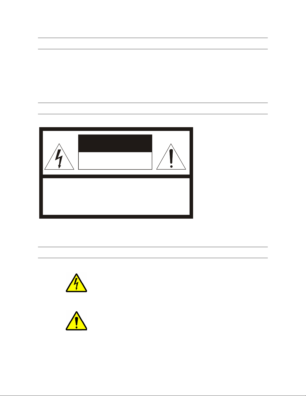
EXPLANATION OF GRAPHICAL SYMBOLS
The lightning flash with arrowhead symbol, within an equilateral triangle, is intended to
alert the user to the presence of un-insulated “dangerous voltage” within the product’s
enclosure that may be of sufficient magnitude to constitute a risk of electric shock to
persons.
The exclamation point within an equilateral triangle is intended to alert the user to the
presence of important operating and maintenance (servicing) instruction in the
literature accompanying the product.
vii

RACK MOUNT INSTRUCTIONS
Elevated Operating Ambient – If installed in a closed or multi-unit rack assembly, the operating ambient temperature of the rack
environment may be greater than ro om ambient. Therefore, considerati on should be given to installing t he equipment in an environment
compatible with the maximum ambient temperature (Tma) specified by the manufacturer.
Reduced Air Flow – Installation of the equipment in a rack s hould be such that the amount of airflow required for safe operation of the
equipment is not compromised.
Mechanical Loading – Mounting of the equipm ent in the rack should be such that a hazardous condition is not achiev ed due to uneven
mechanical loading.
Circuit Overloading – Consideration should be given to the connection of the equipment to the supply circuit and the effect that
overloading of the circuits might have on over curren t protection and supply wiring. Appropriate consideration of equipment nam eplate
ratings should be used when addressing this concern.
Grounding – Grounding of rack-mounted equipment should be maint ained. Particular attention should be given to supply connections
other than direct connections to the branch circuit (e.g. use of power strips).
FCC STATEMENT
This equipment has been tested and found to c omply with the limits for a Class A digital device, pursu ant to Part 15 of the FCC Rules.
These limits are designed to provide reason able protection against harm ful interference when the equipm ent is operated in a commercial
environment. This equipment generates, uses , and can radiate radi o frequenc y energy and, if not insta lled an d used in ac corda nc e with the
instruction manual, may cause harmful interfer ence to radio communications. Operation of this equipment in a residential area i s likely to
cause harmful interference in which case the user will be required to correct the interference at his own expense.
UL NOTICE
Underwriters Laboratories Inc. has not tested the performance or re liability of the security or s ignaling aspec ts of this product. UL has only
tested for fire, shock and casualty hazards as outlined in UL’s Standard for Safety UL 60950-1. UL Certification does not cover the
performance or reliability of the security or signaling aspects if this product. UL MAKES NO REPRESENTATIONS, WARRANTIES OR
CERTIFICATIONS WHATSOEVER REGARDING THE PERFORMANCE OR RELIABILITY OF ANY SECURITY OR SIGNALING
RELATED FUNCTIONS OF THIS PRODUCT.
viii

Table of Contents
PREFACE ............................................................................................................................................................................... 13
About this Guide .............................................................................................................................................................. 13
Technician Notes ............................................................................................................................................................. 13
INTRODUCTION .................................................................................................................................................................... 15
Product Description ......................................................................................................................................................... 15
Features ............................................................................................................................................................................ 16
CONTROLS AND CONNECTIONS ....................................................................................................................................... 17
System Specifications ..................................................................................................................................................... 18
Front Panel Controls and LEDs ...................................................................................................................................... 18
Rear Panel Connectors .................................................................................................................................................... 19
GETTING STARTED .............................................................................................................................................................. 21
Identifying Included Components .................................................................................................................................. 22
Keyboard Setup................................................................................................................................................................ 23
Mouse Setup ..................................................................................................................................................................... 23
Monitor Setup ................................................................................................................................................................... 24
Power Setup ..................................................................................................................................................................... 24
Turning On the IPR .......................................................................................................................................................... 25
Turning Off the IPR .......................................................................................................................................................... 25
IPR BASICS ........................................................................................................................................................................... 27
IPR Registration ............................................................................................................................................................... 28
Locating the System ID ................................................................................................................................................. 28
Obtaining an Unlock Code ............................................................................................................................................ 28
Unlocking a New Network Device ................................................................................................................................. 29
Exporting IPR Settings .................................................................................................................................................... 30
Importing IPR settings ..................................................................................................................................................... 30
Display Screen ................................................................................................................................................................. 31
Live Camera Options ..................................................................................................................................................... 31
Camera View ..................................................................................................................................................................... 32
Recording Status Indicator ............................................................................................................................................ 32
Screen Division Menu ...................................................................................................................................................... 33
SETUP OPTIONS ................................................................................................................................................................... 35
Setup Overview ................................................................................................................................................................ 36
Camera Setup ................................................................................................................................................................... 37
Unlocking a New Network Camera ................................................................................................................................ 38
Connecting a Network Camera ..................................................................................................................................... 38
Motion Setup .................................................................................................................................................................... 39
Creating a Motion Area ................................................................................................................................................. 39
Removing a Motion Area ............................................................................................................................................... 40
Activating an Alarm on a Motion Event .......................................................................................................................... 40
Regular Interval Recording ............................................................................................................................................ 40
Schedule Setup ................................................................................................................................................................ 41
Recording Schedule ...................................................................................................................................................... 41
Sensor Schedule ........................................................................................................................................................... 42
Create a Recording Schedule ....................................................................................................................................... 43
Create a Sensor Schedule ............................................................................................................................................ 43
Scheduling Alarm Events ......................................................................................................................................... 43
Emergency Agent Schedule ..................................................................................................................................... 43
ix

Special Day Schedule ................................................................................................................................................... 44
Creating/Editing a ‘Special Day’ Schedule ............................................................................................................... 44
Deleting a ‘Special Day’ Schedule ............................................................................................................................ 44
System Restart Setup ................................................................................................................................................... 45
Create System Restart Schedule ............................................................................................................................. 45
General Setup ................................................................................................................................................................... 46
Voice Warning ............................................................................................................................................................... 46
Video Loss Alarm .......................................................................................................................................................... 47
Hybrid Sensor Setup ..................................................................................................................................................... 47
Volume .......................................................................................................................................................................... 47
Audio ............................................................................................................................................................................. 48
Enabling Audio Recording ........................................................................................................................................ 48
Enabling Live Audio .................................................................................................................................................. 48
Auto Sequencing Setting ............................................................................................................................................... 49
Create Custom Auto Sequence ................................................................................................................................ 49
Network Setup .................................................................................................................................................................. 50
Information ....................................................................................................................................................................... 51
Administrative Setup ....................................................................................................................................................... 52
Disk Management ......................................................................................................................................................... 52
User Management ......................................................................................................................................................... 53
Add a New User ....................................................................................................................................................... 53
User Rank ................................................................................................................................................................ 54
Changing the Administrator Password .......................................................................................................................... 54
Default Administrator Password ............................................................................................................................... 54
Log Management .......................................................................................................................................................... 54
Setup Log Management Options .............................................................................................................................. 54
Status Check / Email ..................................................................................................................................................... 55
General ..................................................................................................................................................................... 55
Users ........................................................................................................................................................................ 55
Storage Check .......................................................................................................................................................... 56
Recording Data Check ............................................................................................................................................. 56
SMART Information .................................................................................................................................................. 57
SMART Alert ............................................................................................................................................................. 57
Alarm Event .............................................................................................................................................................. 57
INSTANT RECORDING ..................................................................................................................................................... 58
Activate Instant Recording ............................................................................................................................................ 58
Searching ‘Instant Recorded’ Video .............................................................................................................................. 58
SEARCH ................................................................................................................................................................................. 59
Search Overview .............................................................................................................................................................. 60
Play Controls ................................................................................................................................................................. 60
Adjust the Brightness of an Image ................................................................................................................................. 61
Zooming In On an Image ............................................................................................................................................... 61
Zooming in on a Portion of an Image ............................................................................................................................ 61
Open Video from Saved Location.................................................................................................................................. 61
Time Sync ..................................................................................................................................................................... 61
Clean Image .................................................................................................................................................................. 61
Daylight Saving Time ....................................................................................................................................................... 62
Save to JPG or AVI ........................................................................................................................................................... 62
Single Clip Backup ........................................................................................................................................................... 63
Printing an Image ............................................................................................................................................................. 63
Performing a Basic Search ............................................................................................................................................. 64
Index Search ..................................................................................................................................................................... 64
Performing an Index Search .......................................................................................................................................... 64
x

Index Search Results Display ....................................................................................................................................... 64
Preview Search ................................................................................................................................................................ 65
Performing a Preview Search ........................................................................................................................................ 66
Graphic Search ................................................................................................................................................................ 66
Performing a Graphic Search ........................................................................................................................................ 66
Object Search ................................................................................................................................................................... 67
Performing an Object Search ........................................................................................................................................ 67
Search in Live ................................................................................................................................................................... 68
Audio Playback ................................................................................................................................................................ 68
PAN / TILT / ZOOM ................................................................................................................................................................ 69
Pan / Tilt / Zoom Overview .............................................................................................................................................. 70
Setting Up a PTZ Camera ................................................................................................................................................ 70
Attaching the PTZ Adapter ............................................................................................................................................ 70
Enable the PTZ Settings ............................................................................................................................................... 70
Advanced PTZ Setup ....................................................................................................................................................... 71
Creating and Viewing Preset Positions ......................................................................................................................... 71
Creating a Preset ...................................................................................................................................................... 71
Viewing a Preset ....................................................................................................................................................... 71
PTZ Address Settings ................................................................................................................................................... 72
accessing ptz menus ....................................................................................................................................................... 72
Controlling a ptz camera ................................................................................................................................................. 73
Using the Graphical PTZ Controller ............................................................................................................................... 73
Using the On-Screen Compass ..................................................................................................................................... 73
understanding tours ........................................................................................................................................................ 74
PTZ Tour Schedule ....................................................................................................................................................... 75
Create PTZ Tour Schedule ....................................................................................................................................... 75
Supported Protocols ........................................................................................................................................................ 76
BACKING UP VIDEO DATA .................................................................................................................................................. 77
backup overview .............................................................................................................................................................. 78
NERO® EXPREss .............................................................................................................................................................. 78
Backup Center Overview ................................................................................................................................................. 78
General Backup Screen ................................................................................................................................................ 79
Performing a General Backup .................................................................................................................................. 79
Clip Backup Screen ....................................................................................................................................................... 80
Performing a Clip Backup ......................................................................................................................................... 80
Scheduled Backup Screen ............................................................................................................................................ 81
Performing a Scheduled Backup .............................................................................................................................. 81
Specifying Scheduled Backup Drives ....................................................................................................................... 81
LAN / ISDN / PSTN CONNECTIONS ..................................................................................................................................... 83
LAN Overview ................................................................................................................................................................... 84
Connecting to a LAN Using TCP/IP ................................................................................................................................ 84
Configuring TCP/IP Settings ......................................................................................................................................... 84
WEB VIEWER ........................................................................................................................................................................ 85
web viewer overview ........................................................................................................................................................ 86
Configuring the Server for Remote Connection ............................................................................................................. 87
Connecting to an IPR Using Web Viewer ...................................................................................................................... 87
Closing the Web Viewer ................................................................................................................................................ 87
INCLUDED SOFTWARE SETUP ........................................................................................................................................... 89
Emergency Agent Overview ............................................................................................................................................ 90
Configuring the IPR ....................................................................................................................................................... 90
Configuring the Client PC .............................................................................................................................................. 90
Emergency Agent Window ............................................................................................................................................ 91
xi

Setup Window .......................................................................................................................................................... 91
Filter Event List ......................................................................................................................................................... 91
Add Items to Alarm Confirm List ............................................................................................................................... 92
Search Alarm Window ................................................................................................................................................... 93
View Recorded Video ............................................................................................................................................... 93
Export Video ............................................................................................................................................................. 93
Remote Software Overview ............................................................................................................................................. 94
Remote Client Minimum Requirements ......................................................................................................................... 95
Remote Client Recommended Requirements ............................................................................................................... 95
Remote Software Setup ................................................................................................................................................ 95
Installing Remote Software ....................................................................................................................................... 95
Create a New Remote Connection ........................................................................................................................... 96
Configuring the IPR .................................................................................................................................................. 97
Configuring the Server for Remote Connection ........................................................................................................ 97
Access Remote Connection ..................................................................................................................................... 97
Digital Verifier Overview .................................................................................................................................................. 98
Installing the Digital Verifier ........................................................................................................................................... 98
Using the Digital Verifier ................................................................................................................................................ 98
Backup Viewer Overview ................................................................................................................................................. 99
Installing Backup Viewer ............................................................................................................................................... 99
Loading Video from DVD or Hard Drive ...................................................................................................................... 100
SOFTWARE UPGRADES .................................................................................................................................................... 101
SCS Overview ................................................................................................................................................................. 102
Purchasing SCS Software Upgrade ............................................................................................................................ 102
Configuring the Server for Remote Connection ........................................................................................................... 102
Connecting to an IPR .................................................................................................................................................. 102
xii

PREFACE
ABOUT THIS GUIDE
This manual is a setup and maintenance guide that can be used for reference when setting up the IPR unit and for troub leshooting
when a problem occurs. Only authorized personnel should attempt to repair this unit.
Toshiba reserves the right to make changes to the IPR units represented by this manual without notice.
The following text and symbols mark special messages throughout this guide:
NOTE: Text set off in this manner indicates topics of interests that can help the user understand the product better.
TIP: Text set off in this manner indicates topics and points of interests that can be helpful when using or settings up the IPR unit.
TECHNICIAN NOTES
WARNING: Only authorized technicians trained by Toshiba should attempt to repair this IPR unit. All troubleshooting and
repair procedures that may be shown are for re ference and minor re pair only . Becaus e of the c omplexity o f the i ndividual
components and subassemblies, no one s hould at tempt to m ake repairs at the c omponent level or t o make modif icati ons
to any printed wiring board. Improper repairs can c reate a safety hazard. And any indic ations of compon ent replaceme nt
or printed wiring board modifications may void any warranty.
WARNING: To reduce the risk of electrical shock or damage to the equipment:
• Do not disable the power grounding plug. The grounding plug is an important safety feature.
• Plug the power cord into a grounded (earthed) electrical outlet that is easily accessible at all times.
• Disconnect the power from the computer by unplugging the power cord either from the electrical outlet or the
computer.
CAUTION: To properly ventilate your system, you must provide at least 3 inches (7.6 cm) of clearance at the front and
back of the IPR unit.

14

INTRODUCTION
PRODUCT DESCRIPTION
A Surveillix IPR is simply a server that performs as a High Definition Digital Recorder. By utilizing the many features of a computer,
including processing power, storage capacity, graph ics compression, and security features, the IPR unit is more powerful than the
analog recorders of the past.
The Surveillix IPR server software comes pre-configured for fast and seamless integration within your existing IT infrastructure.
Designed around Microsoft® Windows ® XP Embedded, the server software offers unparalleled stabili ty, security, and ease of use.
Accordingly, your security investment has never been easier to maintain. Multiple users may simultaneous ly connect through any
network connection for instantaneous live viewing, digital search, and off site video storage. Us ers can also connect remotely through
DSL, Cable Modems, ISDN, or 56K dial-up. This p owerful software enables users to establish recording schedules , create motion
detection zones, use PTZ controls, and configure alarm inputs and outputs for each of the system's cameras. With the latest
advancements in the IPR Server Software, searching and index ing y our vide o archive has nev er been eas ier. Video c an now be found,
viewed, and exported in a number of file formats with just a few clicks.
The Surveillix IPR is high performance security product ready to meet today’s security demands.
15

FEATURES
Toshiba’s Surveillix IPRs include the following new features:
Optimized and Designed for Microsoft® Windows XP Embedded®
Up to 16 Network Based Video Inputs
Remote System Operation & Configuration
Supports Multiple Simultaneous Remote Connections
PAN / TILT / ZOOM Controls via IP Protocols
Simultaneous Video Search, Playback and Backup
Video Indexes for Easy Searching
Multiple Levels of Security Access
Up to 1 Channel of Audio Recording
Up to 1 Terabyte Internal Storage
High Performance, Durable, Rack mount Case
Output the Video to a NTSC/PAL Display
Digital Signature Support
Continuous, Motion Detection, Alarm, Pre-Alarm, and Scheduled Recording Modes
Records at the encoding resolution of the network camera
Multi-Site Management Software Support (optional upgrade)
16

CONTROLS AND CONNECTIONS
This chapter includes the following information:
• Input / Output Connector Locations
• Front Panel Controls and LEDs
• Rear Panel Connectors
17
SYSTEM SPECIFICATIONS
Surveillix™ state-of-the-art Network Video Recorders are housed in a high performance and versatile 3U Rack-Mount case allowin g
easy storage of multiple IPRs for enterprise applications. Every Surveillix IPR unit comes equipped with the latest technology:
Intel® Pentium® IV Processor
100/1000 Gigabit Ethernet
512 MB (8 Channel) / 1 GB (16 Channel) of System Memory
128 MB Video Card
DVD RW Recorder
250 GB Video Storage Drive (minimum)
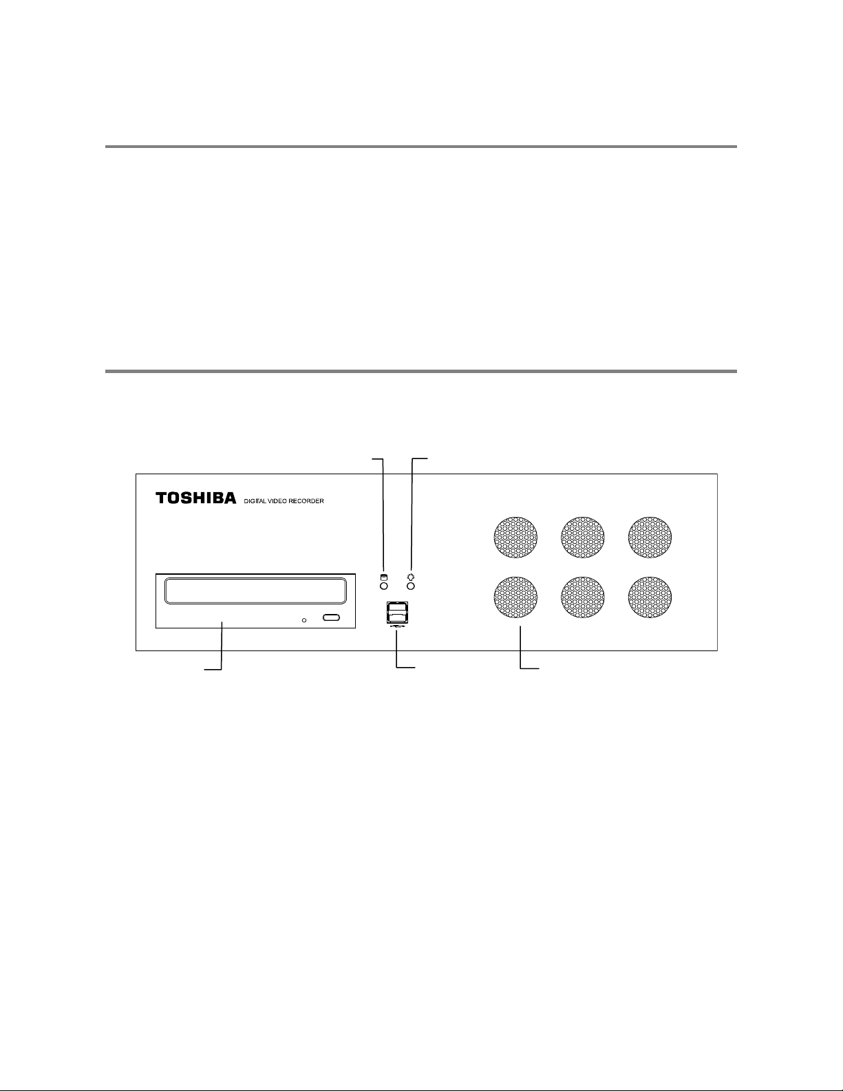
FRONT PANEL CONTROLS AND LEDS
The front panel of the IPR unit contains the devices that will b e commonly used for d ata removal, retrieval, and backup replac ement.
The most common components and buttons are shown below:
DVD±RW Drive
Hard Drive Activity LED
Power LED
USB Ports
Cooling Fan Intakes
18

t
t
REAR PANEL CONNECTORS
The rear panel of the IPR unit contains the connectors us ed to attach cameras, sensors, and rel ays to the IPR. Below are diagrams
that outline the location and description of each connector:
RJ-45 Network Jack
IEEE AC Power Connector
S-Video Out
Cooling Fan
PS/2 Mouse Inpu
PS/2 Keyboard Inpu
DB-9 Serial Input 1
LPT Parallel Printer Port
SVGA Output
USB Ports
DB-14 SVGA Monitor Output
Audio
• Line In – line level
• Speaker Out
• Microphone In – not used
Power Switch
19

20

GETTING STARTED
This chapter includes the following information:
• Included Components
• Setting Up the IPR Hardware
• Optional Components
21
r
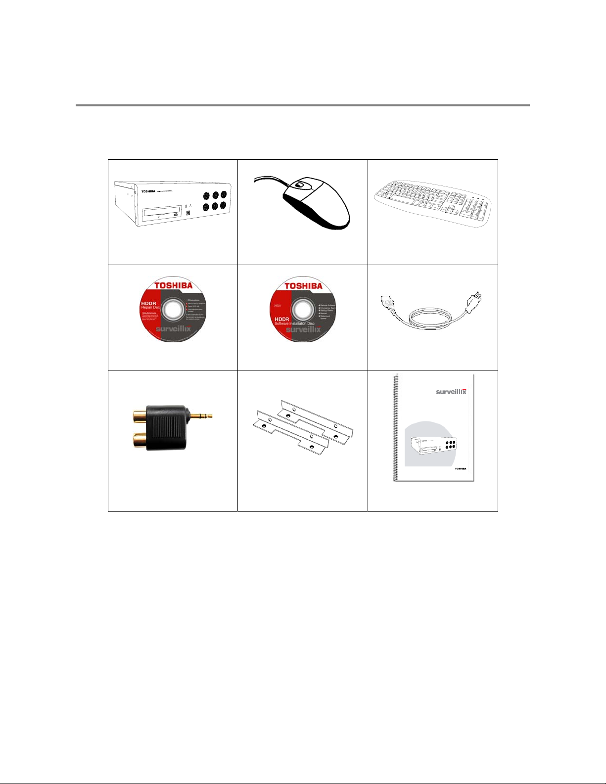
IDENTIFYING INCLUDED COMPONENTS
Surveillix™ IPRs c ome with a mouse, keyboard and selected so ftware and cables. Identify the followin g components to make sure
everything has been properly included wi th the new IPR uni t. If any of t he following items are missing, co ntact the dealer to arrange a
replacement.
IPR Unit Mouse Keyboard
Repair Disc Software Disc Power Cable
Digital Video Recorde
Audio Adapter
Rack Mount Attachments with
Screws
Please carefully read these instructions before using this product.
Save this manual for future use.
1
IPR Manual
model no.
UserManual
IPR
IPR8-X
IPR16-X
22

KEYBOARD SETUP
To attach the keyboard to the IPR unit, plug the
end of the Keyboard into the keyboard PS/2 Port
located on the back of the machine.
The keyboard PS/2 Port can be identified by the
purple color.
Refer to the Rear Panel Connectors diagram for
more information.
MOUSE SETUP
To attach the mouse to the IPR unit, pl ug the end of the mouse into th e mouse PS/2 Port located on the back of th e machine. The
mouse PS/2 Port can be identified by the green color.
The mouse uses a cursor called a pointer. Pointers come in many different shapes but are most commonly shaped like an arrow.
The mouse has two buttons: a left button and a right button. Quickly pressing and releasing one of t hese buttons is called clicking.
Sometimes you will need to double-click – or click the same button twice quickly.
In this manual:
Click means to position the mouse cursor over an item and to single click the left button.
Right click means to position the mouse cursor over an item and to single click the right button.
Double-click means to position the mouse cursor over an item and to click the left button twice.
Select means to position the mouse cursor over a radio button, checkbox, or list item and click on it.
The scroll wheel in between the two buttons is used for added navigation functionality. By moving the wheel with index finger
(scrolling), quickly move through multiple p ages, lines, or wind ows. The wheel may als o function as a th ird button allowing t he user t o
quickly click or double-click an icon or a selected item.
Scroll Button / Third Button
Left Button
Right Button
23

MONITOR SETUP
The IPR may have one or both of the following connections available for monitors which can be used individually or in tandem.
SVGA Output* To VGA Monitor.
Attach the monitor or monitors to the rear of the IPR unit using the cable supplied by the monitor manufacturer. Refer to the monitor
manual for detailed information on how to setup and use it.
NOTE: The monitor must be capable of having a screen resolution of 1024 x 768 and display colors of at least 32 Bit.
* Use the SVGA Output on the Video Card labeled as the DB-14 SVGA Monitor
Output on the Rear Panel Connectors diagram.
S-Video Output To TV/VCR.
POWER SETUP
WARNING:
To reduce the risk of electrical shock or damage to the equipment:
Do not disable the power grounding plug.
The grounding plug is an important safety feature.
If the electrical plug you are using does not have a ground plug receptacle contact a licensed
electrician to have it replaced with a grounded electrical outlet.
Plug the power cord into a grounded (earthed) electrical outlet that is easily accessible at all times.
Disconnect the power from the computer by unplugging the power cord either from the electrical
outlet or the computer.
24

TURNING ON THE IPR
1. Turn on the monitor and any external peripherals (ex. Printers, External Storage Devices, etc.) connected to the IPR unit.
2. Turn on the Power Switch located in the rear of the IPR unit.
3. The IPR will run a series of self-tests. After two or three minutes, a series of messages may be dis pl ay ed as th e v arious hardware
and software subsystems are activated. Under normal circumstances, users should not be asked to respond to these messages.
If asked to respond to the messages (adding a Printer, Monitor, etc for the first time) follow the instructions carefully.
4. Startup is complete when the Surveillix™ IPR software is finished loading and displays the main menu screen.
TURNING OFF THE IPR
1. Click the Exit Button on the main menu screen of the IPR software.
2. Select Power Off from the drop down menu, which appears in the Power Off prompt, and click OK.
The IPR unit may take several minutes to shut down completely.
CAUTION: Always be sure to follow the proper procedures when turning off the power to the IPR unit. NEVER disconnect the power
to the IPR unit while it is still running or in th e pr oc es s of s hutting down. Doing so can cause data l os s , file c orrupti on, system instability
and hardware failure.
25

26

IPR BASICS
This chapter includes the following information:
• Registration and Upgrade
• Turning the IPR on and off
• Becoming familiar with the Display screen
• Defining Screen Divisions
27

IPR REGISTRATION
Important Information
Have the following information on hand before registering the IPR upgrade:
IPR Software Serial Number: The Product Serial Number is the unique number that Toshiba provided with the software.
System ID: The System ID is a number generated by the IPR Software. This is a unique code g ener ated using the MAC ad dre ss
of the computer running the software. The following steps illustrate how to obtain the unique System ID.
Locating the System ID
1. Enter Setup.
2. Click Camera Setup.
3. Click the Registration Button.
4. In the Network Device Authentication Window, the System
ID is located in the “Add a new Serial Key” section.
Obtaining an Unlock Code
The following steps are provided to assist in registering the IPR upgrade.
1. Open an Internet browser and to http://register.surveillixdvrsupport.com
2. Enter the Product Serial Number provided by Toshiba.
3. Enter the System ID generated by the IPR Software.
4. Click Submit.
28
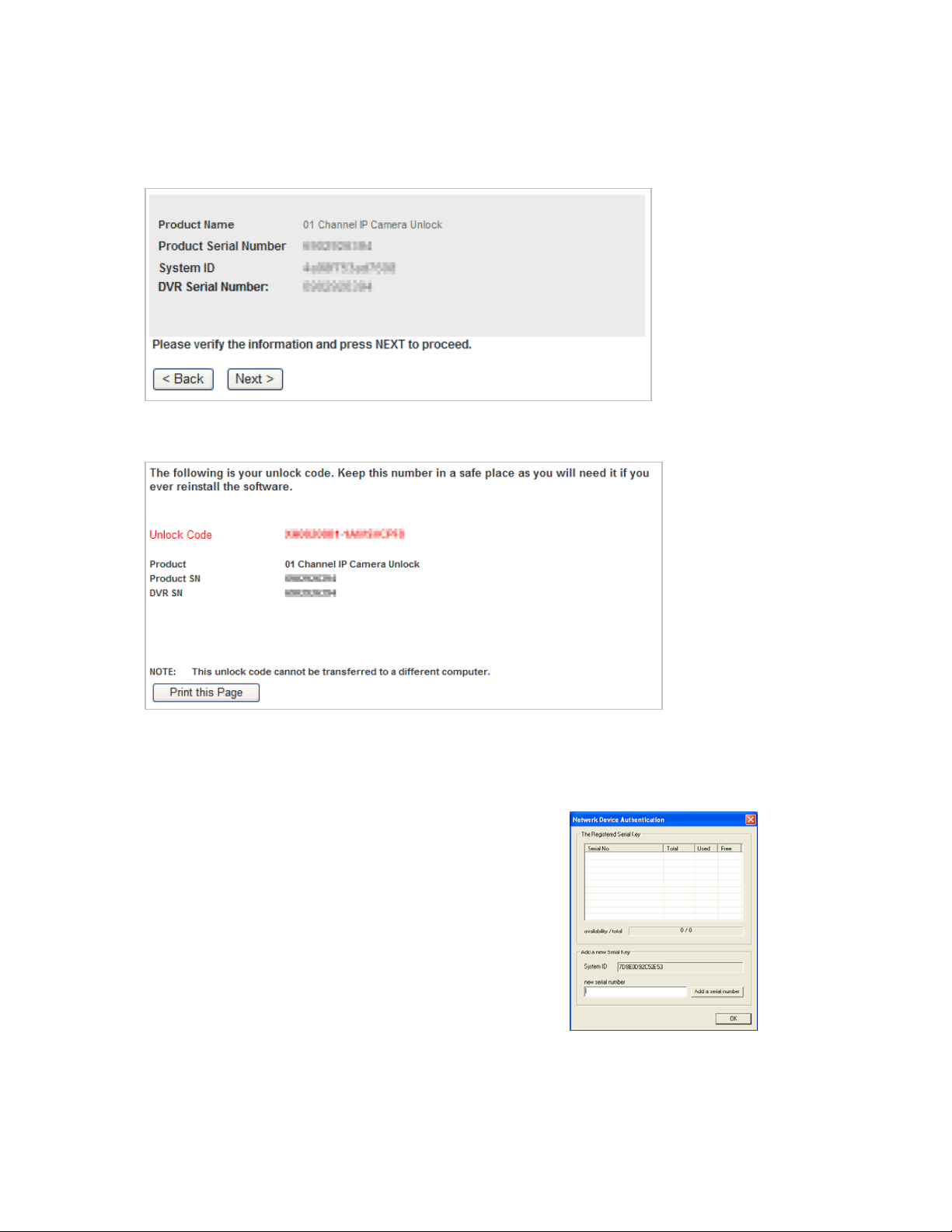
5. Verify the information.
6. Click Next if the information provided is correct.
7. Once the information is validated, the unlock code will be generated.
8. Print the page and save for later reference.
Unlocking a New Network Device
After obtaining your unlock code from the Toshiba Surveillix Regis tration Site, follow theses steps to unlock your new upgrades on your
Surveillix IPR.
1. Start the Surveillix IPR.
2. Enter Setup.
3. Enter Camera Setup.
4. Click the Registration Button.
5. Enter the Unlock Code generated by the Surveillix
Registration Site into the “new serial number” field.
6. Click Add a Serial Number.
7. Once the new serial number has been added to the list,
click OK.
29
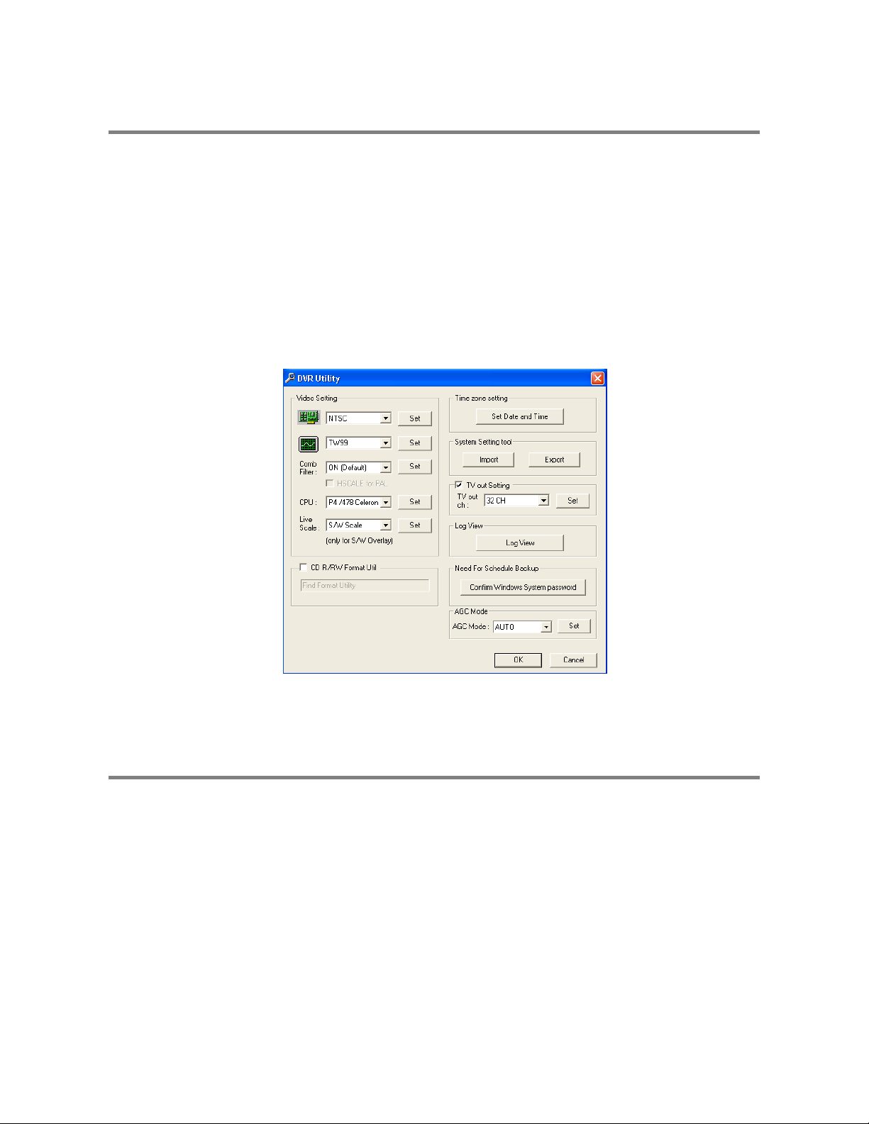
EXPORTING IPR SETTINGS
Exporting IPR settings can help configure multiple IPRs quickly or reconfigure a unit that has failed. Som e things must be k ept in mind
when using this feature.
You cannot use this function on:
1. Exit to Windows by clicking the Exit Button on the Main Display Screen and selecting Restart in Windows Mode. (See the Display
2. Click Start > Programs > Surveillix > VFormat
3. Click the Export Button in the System Settings tool section.
• IPRs that are different models.
• When upgrading from certain software versions. You cannot use this feature when upgrading from
v1.x to v2.x
Screen section later in this chapter)
4. Select a location to save the settings file and click Save. The DVR Utility will export the IPR settings and automatically close.
5. Click the OK Button to close the VFormat Utility.
IMPORTING IPR SETTINGS
1. Exit to Windows by clicking the Exit Button on the Main Display Screen and selecting Restart in Windows Mode. (See the Display
Screen section later in this chapter.)
2. Click Start > Programs > Surveillix > VFormat.
3. Click the Import Button in the System Settings Tool section.
4. Select the location of the settings file to import and click Open.
5. Click Yes to import the data file.
6. Click the OK Button to close the VFormat Utility.
30

/
DISPLAY SCREEN
Each time the IPR is started, the program defau lts t o the Display screen. The following diagram outlines the buttons and features used
on the Display screen. You should b ecome familiar with these options as this is the screen that will be dis played the majority of the
time.
Opens:
• Search Display
• Backup Center
• PTZ Controller
Opens Setup Display
Screen Division buttons
Current Date
Time
Live Camera Options
Right-click a live camera to display these options:
• Full Screen
• Instant Recording
• Search In Live
Open TV Out Options
31

CAMERA VIEW
The Camera status for each camera is displayed next to the Camera number (or name) on the Video Display Area.
Recording Status
Special Recording Type
INSTANT
Camera No. and Name
Recording Status Indicator
The camera status for eac h camera is displayed in the upper right corner on th e Video Display Area. The followi ng are the different
states for each camera:
There are two types of IPR Special Recording. Text is displayed on the camera indicating what type of Special Recording is activated.
SENSOR Sensor is displayed when a sensor, associated with a given camera, is activated.
INSTANT Instant Recording is a manual activation of the recor ding for the selecte d camera. Regardl ess of the recordin g method,
Recording Displayed when the camera is currently being recorded to the IPR unit.
Motion Detection Displayed when a camera (set up for motion detection) detects motion.
Display Displayed when the camera is currently not being recorded to the IPR unit.
Instant Recording will start the camera recordin g and also flag the video for future searches using th e Index Search
feature. INSTANT is displayed when a user activates the insta nt recording option. Doubl e Right-Click the video dis play
to activate and deactivate the Instant Recording option.
32

SCREEN DIVISION MENU
The Screen Division Menu allows you to view cameras in groups such as two by two, three by three and four by four. The button
options are shown below.
1st Four Cameras View – Displays cameras 1-4 in the Video Display Area. To return to a di ffere nt Multi-Camera View,
select a different Screen Division option from the Screen Division Menu.
2nd Four Cameras View – Displays cameras 5-8 in the Video Disp lay Area. To return to a different Multi-Camera
View, select a different Screen Division option from the Screen Division Menu.
3rd Four Cameras View – Displays cameras 9-12 in the Video Display Area. To return to a diff erent Multi-Camera
View, select a different Screen Division option from the Screen Division Menu.
4th Four Cameras View – Displays cameras 13-16 in the Video Display Area. To return to a different Multi-Camera
View, select a different Screen Division option from the Screen Division Menu.
1st Nine Cameras View – Displays cameras 1-9 in the Video Display Area. To return to a di ffere nt Multi-Camera View,
select a different Screen Division option from the Screen Division Menu.
2nd Nine Camera View – Displays cameras 8-16 in the Video Display Area. To return to a different Mu lti-Camera
View, select a different Screen Division option from the Screen Division Menu.
Multi-Camera View – Displays a group of cameras within the Video Display Area.
All Camera View – Displays all 16 cameras within the Video Display Area.
Multi-Camera View – Displays a group of cameras within the Video Display Area.
Multi-Camera View – Displays a group of cameras within the Video Display Area.
Full Screen – The Full Screen Option allows you to v iew the Vide o Display Area usi ng the entir e viewa ble ar ea on th e
monitor. When this is selected, no menu options are visible. You can activate the Full Screen Optio n by clicking on
the Full Screen Button within the Screen Division Menu . You can de activate Fu ll Screen mo de by right clic king on th e
screen.
Auto Sequence – Sequences through the Screen Divisions sets . For example, selecting the 1A and then the L oop
Button will sequence through 1A, 2A, 3A, 4A and then repe at. This optio n is not available f or the 7, 10 and 13 screen
divisions.
33

34

SETUP OPTIONS
This chapter includes the following information:
• Setup Overview
• Add Network Recording Device
• Channels
• Color
• Schedule
• Speed
• Motion Detect
• Password
• Pan/Tilt
• Audio
35

SETUP OVERVIEW
The S etup options allow you to optimiz e the IPR u nit by adjustin g things like cam era names ,
reboot schedules, recording schedules and more. It is ex treme ly important that you setup the
IPR correctly for several reasons.
• Recording Schedules – By optimizing the recording schedule you can increase the
amount of pertinent recorded video that is saved on the IPR and keep it longer. You
can optimize the type of recording done by adding motion detection to this as well,
again increasing the amount of useful video.
• IPR Access – By setting up the access passwords you can tightly control the types of
access an individual may have. This ensures the security and integrity of the IPR unit.
• Camera Naming – By naming each camera you can easily identify the location and
any other pertinent information that may be helpful simply by viewing it on the Video
Display Area.
• Adjusting Camera Color – By adjusting each camera’s color settings you can
optimize the clarity and detail that is recorded.
36

play
CAMERA SETUP
Selected Camera
Dis
Define Camera Name
Select Camera Selects the camera to be edited.
Selected Camera Display Displays the live camera feed from the camera selected.
Sensor Connection Specify which sensors are currently in use.
Enable Network Device PTZ Enables setup and use of Network Camera and PTZ Functionality.
Setup Network Device Opens the Network Device Setup menu.
Registration Opens the Registration menu for entering Unlock Codes to activate the software.
Online Registration Opens the Online Registration menu for activating pre-registered software.
Camera Name Specify a name for each camera.
37

Unlocking a New Network Camera
1. Start the Surveillix IPR.
2. Enter Setup.
3. Enter Camera Setup.
4. Click the Registration button.
5. Enter the Unlock Code generated by the Toshiba
Registration Site into the “new serial number” box.
6. Click Add a serial number.
7. Once the new serial number has been added to the list,
click OK.
Connecting a Network Camera
1. Open Camera Setup. Setup > Camera Setup.
2. Select the camera channel to add a Network Device to.
3. Check the Use Network Device Box.
4. If the Network Device supports PTZ check the Enable Network
Device PTZ Box.
5. Click Setup Network Device and the Network Device Properties
window will appear.
6. Click Setup to add a Network Device.
7. Select the Manufacturer (Class) and Model of camera being added
then click Next.
8. Enter the IP Address, Port, ID, and Password of the Network Device
and click Finish.
9. Click OK when returned to the main Network Device Properties
window.
10. Click Apply and then click OK to exit the main setup window.
11. The Network Device has been added.
38

MOTION SETUP
The IPR allows the user to adjust several different Motion Settings and create motion detection regions.
NOTE: Motion grids configured using the SCS software will be advanced motion grids.
Display full screen video
pop up on motion event
Beep on motion event
Display full screen video
pop up on sensor event
Schedule recording at a regular specified interval
Reduces Analog Signal Noise from Motion Detection
Creating a Motion Area
1. Click the Motion button in Setup.
2. Select a camera from the Select Camera list.
3. Select the Detect Detail Motion Area check box.
4. Click Clear.
5. Click Advanced Motion Area Setup.
6. Click a Motion Detection Area shape button.
7. Drag the mouse over the camera image.
TIP: To create a polygon shape, click the mouse at each point and
double-click to close the shape.
8. Click OK.
9. Move the sliders to adjust motion sensitivity and the noise filter.
10. Define the pre-alarm and post-alarm recording time for a motion
event.
Pre Alarm – 0 > 50 Seconds [The number of seconds the IPR
records before motion is detected]
Post Alarm (MOTION) – 0 > 50 Seconds [The number of seconds
the IPR records after motion is detected]
39

Removing a Motion Area
To remove the motion areas, in the Motion Regions area, click Clear.
Activating an Alarm on a Motion Event
1. In the Motion Setup window, select a camera to edit from the list.
2. Create a motion area.
3. Select the Alarm Output check box.
4. Select a Control Output to activate for the selected camera.
5. Select the duration to activate the Alarm when a motion event occurs.
Regular Interval Recording
Regular Interv al Recording allows u sers to record a single fra me every few minutes or hours when there is n o motion. This opt ion is
only available when Motion recording or Sensor recording is setup.
To enable Regular Interval Recording:
1. Select the Regular Interval Recording check box.
2. Specify how often to take an image when no motion is occurring. Users can go as little as one image per second.
40

/
t
w
SCHEDULE SETUP
Recording Schedule
The Recording Schedule window allows the us er to create diff erent recording sc hedules bas ed on the day, time, a nd type of rec ording
desired. In addition, this window contains the System Restart options that allow the user to perform basic system maintenance by
automatically scheduling the IPR to restart periodically.
Recording Schedule Windo
Single Day Selection
Multi Day Selection
Open Restar
Setup Window
Create Special Day
Recording Schedules
Recording Mode Options
Emergency IP Setup
41

/
t
w
y
Sensor Schedule
The sensors will supersede all other types of recording modes (Motion, Continuous, No Recording). Regardless of the recording
schedule of a particular camera, if a sensor event oc curs the associated cameras will begin recording as a Sensor Event. Sensor
Recordings will be flagged and searchable using the Index Search Mode. Cameras are a ssociated to sensors in the Camer a Setup
Menu.
Sensor Schedule Window
Alarm Options
Single Day Selection
Multi Day Selection
Emergency IP Setup
Open Restar
Setup Windo
Create Special Da
Sensor Schedules
42

Create a Recording Schedule
1. Select a day to begin creating the schedule for -or- Select the Day Selection Mode button, enabling
Multi Day Selection, to create the same schedule for multiple days.
2. Highlight the Time-Blocks within the Recording Schedule window for the camera(s) selected to schedule. Once the desired
Time-Blocks are highlighted, click a Recording Mode button. The Time-Blocks should now appear Blue for Motion, Yellow for
Continuous and White for No Recording
NOTE: Leave cameras recording with Sensor Detection set to No Recording for the specified time block(s).
Create a Sensor Schedule
1. Select the Schedule Menu option and select the Sensor Radio button. Select a single day or click the Day Selection Mode
button to include multiple days in the schedule.
2. Highlight the Time-Blocks within the Recording Schedule window for the sensor(s) to enable and schedule. Once the time
blocks are highlighted click the Enable button. The time block will now appear red.
Scheduling Alarm Events
There are three types of Alarm Events:
ALARM EVENT: This option logs the Alarm Events on the local server.
CENTRAL STATION: This option sends the Alarm Events to Central Station software.
EMERGENCY AGENT: This option sends the Alarm Event to the Emergency Agent software.
Motion can be designated as an Alarm ev ent. Often motion does not need to be treated as an Alarm event. Ex: During work hours
motion that occurs is expected and should not be treated as an Alarm. However, after business hours are over, any motion that
occurs should be treated as an Alarm.
1. Select the Schedule Menu – Select either Recording or Sensor
2. Highlight time blocks in the schedule that have been set to Motion (or Sensor) and click the desired Event buttons (Alarm Event,
Central Station, Emergency Agent). A corresponding letter will display in the selected time blocks
Emergency Agent Schedule
Video recording triggered by motion or sensor events can be sent to the Emergency Agent software.
1. Enable the Emergency Agent Event (see Scheduling Alarm Events above)
2. Enter the IP Address of a PC running the Emergency Agent software in the IP Address
3. Select the box next to the IP Address to enable it. Only one IP Address is supported at a time.
4. Enter the recording duration (in seconds) in the Emergency Time box.
5. See the Emergency Agent chapter for detailed information on setting up the Emergency Agent software.
43

r
Special Day Schedule
The user can create days that have a unique recording schedule . If necessary create these on days that are ‘not typical’ such as
Holidays, Special Events, etc.
Special Day Mode / Normal Day Mode
Date Ba
Configured Special Days List
Creating/Editing a ‘Special Day’ Schedule
1. Click the Normal Day Mode button to enable the Special Day Mode.
2. Select a day by typing the date or clicking the arrow to the right of the Date Bar.
3. Highlight the time-blocks within the Recording Schedule window for the camera(s) selected to schedule. Once the desired TimeBlocks are highlighted, click a Recordi ng Mode button.
4. When finished creating the schedule click the Save Special Day button. The special day should now appear as a date in the
Special Day Schedule.
Deleting a ‘Special Day’ Schedule
1. Select a Special Day from the Special Day Schedules
2. Click the Delete Special Day button.
44

System Restart Setup
System Restart Setup allows the user to define a schedule wherein the IPR automatically restarts according to specified parameters.
Create System Restart Schedule
1. Open the Schedule Setup Display
2. Click the System Restart button
3. Select the day(s) of the week to schedule an automatic system restart and select the box to enable shut down
NOTE: This step alone does not trigger the IPR to restart, only to shut down.
4. Specify the time of day to schedule the system restart
5. Select the Restart Radio button
NOTE: If the Off Radio button is selected the IPR will shut down at the specified time but not restart.
45

GENERAL SETUP
Adjust / Mute Volume
Enable Audio Recording
Beep on Login Fail Enab les the IPR to beep continuously in response to a failed login attempt. Only an auth orized login will stop
the beeping.
Sequence Setting Allows the video out picture to automatically cycle through channels at a set speed. Ex: .Cycle through
channels 1-6 at 4 second intervals.
Voice Warning
The IPR allows users to play a sound fil e when either a Motio n event or Sensor eve nt occur. This file can b e a custom create d sound
file that is unique to the application. The selected WAV file is played through speakers attached to the IPR.
Open Sound File
1. Click the Open Sound File icon to browse for a WAV file. The selected file will display in the box on the left.
2. Click the Test icon to verify the audio file.
3. Select Motion Event and/or Sensor Event to trigger the audio file.
Test
46

Video Loss Alarm
The IPR Software supports a Vi deo Loss Alarm fu nction, wh ich a llows a n Alar m Even t to l og when a cam era l oses its signal. The lost
signal can be due to Power failure to the network device, the network device cable being c ut or unplugged, or the network device
being damaged in some way.
Video Loss Alarm Beep When Video Loss occurs the speaker attached to the IPR will sound an alarm.
Video Loss Alarm Log Records the Video Loss Alarm Events to the log files.
Hybrid Sensor Setup
This interface is used to link Hard Contact Sensor Inputs from supported Network Devices to the IPR Software.
Volume
The volume control allows fine tuning of the volume settings on the IPR.
Volume Options:
• Slider Controls – Used to adjust the literal volume for the
respective devices listed.
• Mute Checkbox – Check the mute box to mute volume on
any of the device columns or check the Mute All checkbox to
mute all volume on the IPR.
47

Audio
The Surveillix IPR is capable of recording one channe of audio.
AUDIO FEATURES:
• 8000 Hz playback in Live Mode
• Up to 48000 Hz playback in search mode
• Mono Sampling
DATA SIZE (Per channel)
• 1 Second: 1625 bytes
• 1 Minute: 97,500 bytes
• 10 Minute: 975,000 bytes
• 1 Hour: 5,850,000 bytes
• 1 Day: 140,400,000 bytes (Approx 140MB)
Click the Audio Capture Channel Boxes to enable recording and adjus t the
Gain to the desired level.
Capture Select each channel to enable audio recording.
Gain Adjust the gain for individual audio channels.
Live Select each channel to enable for live audio selection.
Audio Live Select a live audio channel to hear. Only enabled channels
are available.
Volume Adjust the volume sliders for each live audio channel.
Enabling Audio Recording
1. Click the Audio button on the General setup display.
2. Select an audio channel under Capture.
3. Click OK.
Enabling Live Audio
1. Click the Audio button on the General setup display.
2. Select an audio channel under Live.
3. Click OK.
TIP: Select the audio channel you want to listen to by clicking the Audio Live button and selecting it in Audio Setup. Live audi o
channels can also be selected from the Main Screen; only audio channels enabled under Live will be available.
48

Auto Sequencing Setting
Auto Sequencing is used either in the main screen when Auto Sequenci ng has been enabled or when a Spot-Monitor Out signal is
used to display video on a spot m onitor. Auto S equencing conv eniently displ ays video c hannels and at specified in tervals, seque nces
through each selected channel.
Screen Division Options
Enable Sequencing
Enable All Cameras
Select interval between
switching cameras
Channel Selection Click each channel to include in Auto Sequencing.
Custom Mode Enable to create non-standard screen divisions
Skip 0 FPS Channel Sequence skips cameras with no video signal.
Create Custom Auto Sequence
1. Open General Setup and click the Sequence Setting button.
2. Click individual cameras in the left pane or click the Select All button to include all cameras in the sequence.
3. Select an interval time (in seconds) to display each screen in the sequence.
4. Select Screen Division options for appropriate cameras.
5. Click the OK button.
49

t
NETWORK SETUP
Network Setup allows the user to adjust settings such as ports, setup emergency PPP information for use with the Emergency Agent
and enable Remote Access.
Settings for Video Sen
to Remote Client
Use with Remote
Connections
Enable RS-232
Keyboards (PTZ)
Transport Rate A bandwidth throttle based on percentage of free network.
Web Viewer (iDVR) Enables/Disables access to the IPR using the Web Viewer interface.
Use with
Emergency Agent
50

r
INFORMATION
The Site Information Window allows users to define the site code necessary for connecting to remote software, save comments
relative to the IPR and store tech support and contact number information.
Total HDD /Available HDD Space
Enter comments
Current Serve
Software Version
User-Defined
Contact Numbers
Site Code A user-specified unique identification name that is used by other IPR software to c onnect
to the IPR. (Remote, Emergency Agent, SCS, Digital Signature Verifier)
51

y
ADMINISTRATIVE SETUP
The Log Vi ewer di splays detail ed informat ion a bout the IPR, incl uding Shut D own and Res tart informa tion, U ser Lo gins and Re cor ding
problems and failures. This can be a valuable tool to Administrators.
Select Date
Log Data Displa
Export Log Data (1 to 7 days)
Disk Management
The Disk Management wi ndow is a native Windows func tion. This window displays the partition scheme and health status of the Hard
Disk Drives in the IPR. This window is often used to troubleshoot an IPR, or verify the amount of Hard Drive storage installed. For
more information about Disk Management, consult a Windows XP manual.
52

f
User Management
The User Mana gement Co nsole a llows the adminis trator to c reate, edit, and dele te user ac counts . Each user ac count c an be as signed
different privileges to limit the usage of the IPR system. Users can be given administrator privileges by enabling all rights, however
only the true administrator account can log into the User Management Console.
Enable Auto Log Of
Log Off User after x Minute(s) of Inactivity*
*Auto Log Off affects all users
CAUTION: The Delete User button immediately deletes the user.
CAUTION: Auto log off will log off the user after the specified time of inactivity – even during playback or backup operations.
Add a New User
1. Open the Administrative Setup display.
2. Click the User Management button.
3. Click Add User to open the User Management window.
4. Enter a user name and password.
5. Enable appropriate Permissions.
6. Select cameras and audio channels to hide from the user.
7. Assign a User Rank.
8. Click the OK button to save changes and close the window.
53

User Rank
The User Ranking structure allows the option to assign a privilege system (1-10 where one has the most rights) to users of the IPR
Software. For example: Since only one user is allowed to use the PTZ controls at any one time, an adminis trator with a higher rank
can kick another user out and take control of the PTZ.
The User Rank option affects:
SETUP ACCESS – Only one user can access Setup at any one time. A user with a h igher rank will kick another user out and then
open Setup.
PTZ CONTROL - The IPR Software can only have 1 user using the PTZ controls at any giv en time. A user with a hi gher rank will kick
another user out and then open the PTZ controls.
1. Enter Setup.
2. Click the Administrative button.
3. Click the User Management button.
4. Enter the Administrator password and click OK.
5. Select a user from the Select User box and click the Update User button.
6. Set the user’s rank using the User Rank list and press the OK button to save changes.
Changing the Administrator Password
1. Inside Administrative Setup, click the User Management button. When the prompt appears, click the Change Password button.
2. Enter the new password in the prompt that appears and click OK.
Default Administrator Password
The default administrator login is:
User: Administrator
Password: <none>
Log Management
The Log Management window provides the user the options to overwrite log files or schedule log deletion.
Setup Log Management Options
1. From the Administrative Setup Display click the Log Management button
2. Select the box to enable the Log File Overwrite Option
Set Log Overwrite
a. Select Overwrite and define the size of the log file cache
Set Log Cache Size
a. Select Do Not Overwrite and define the number of days to maintain log files.
Manually Delete Log Files
a. Select the type(s) of log file to delete. System Log, Event Log, Alarm Log
b. Click the Delete All button
3. Click the OK button to save the settings and close the window
54

Status Check / Email
General
1. Click the Setup button on the Main Display.
2. Click the Administrative button.
3. Click Status Check/Email.
4. Select the Enable Email Alarm check box.
5. Enter a From Name and e-mail Address.
NOTE: This name and address will appear in the From line of the email alert
message.
6. Enter the SMTP information for the “from” email account. Contact the
email administrator for this information if necessary.
7. If using a secondary email account select the Use Secondary SMTP
Box and complete the SMTP information.
8. Click the Test button to check settings.
9. Click Apply when finished.
Users
1. Setup the General tab.
2. Click the Users tab.
3. Select the type of event to send email on.
4. Enter the User Name and Email Address of an email recipient.
5. Click the Add button.
6. Repeat for additional recipients and types of events.
NOTE: A separate email notification for each type of event must be
set up for a single recipient to receive notifications for each type of event.
7. Click Apply when finished.
55

Storage Check
1. Setup the General and Users tabs first.
(see above)
2. Select the Use Storage Check check box.
3. Define the number of minutes.
4. Select an Alert Option, Beep or Popup Message, if desired.
5. Click Apply.
Recording Data Check
1. Setup the General and Users tabs first.
(see above)
2. Select the Recording Data Check check box.
3. Define the number of hours between data checks.
4. Select the Action Method.
5. Click Apply.
56

SMART Information
The SMART Information tab displays Hard Drive information.
SMART Alert
1. Setup the General and Users tabs first.
(see above)
2. Select the Enable SMART Alarm.
3. Define the number hours between SMART checks.
4. Select the type of SMART event to trigger an action.
5. Define the maximum HDD temperature.
6. Select an action method.
7. Click Apply.
Alarm Event
1. Setup the General and Users tabs first.
(see above)
2. Select the Use Email Alarm check box.
3. Define the number of minutes between recordi ng data checks.
4. Select Motion and/or Sensor to send and alert on that type of event.
5. Click Apply.
6. Click Close to return to the Administration tab.
57

INSTANT RECORDING
The Instant Recording feature allows users to manu ally initiate r ecordi ng on a spec ific ca mera, overridi ng the current s ched ule . When
Instant Recording is activated the IPR flags the clip as an event so Instant Recording instances can be found using the Index Search
Ins tant Recording c an be used, for example, when a s uspicious ob ject or person is detected and the user wants to flag that sec tion of
video for easy retrieval at a later date.
Activate Instant Recording
1. From the Live View screen, double right-click the camera on which to enable instant recording. An INSTANT label will be placed
on the upper right corner of the video.
2. To turn the Instant Recording option off, double right-click the video a second time.
Searching ‘Instant Recorded’ Video
Enter the Search Mode, click the Index Search button , and the n s elec t t he Ins ta nt Rec ord i ng Opti on. See the Search chapter for more
information.
58

SEARCH
This chapter includes the following information:
• Search Overview
• Play Controls
• Index Search
• Preview Search
• Object Search
• Graphic Search
59

A
SEARCH OVERVIEW
The IPR unit has several options that allow the user to easily search through, and find, a particular section of video. From
Motion/Sensor indexing to calendar views highli ghting days with rec orded video; the IPR unit is equ ipped to help the user q uickly find
a specific video or event.
The following chapter describes in detail how to use the IPR Search features.
Screen Division buttons
Calendar button
udio Channels
Playback Date/Time
Current Date/Time
Hour/Minute Control Bar
Play Controls
Play Controls
Rewind
Back Frame
60
Stop
Play
Forward Frame
Camera Select buttons
Back Frame Moves video back one frame.
Rewind Rewinds video.
Stop Stops video playback
Play Plays video.
Forward Frame Moves video forward one frame.

Adjust the Brightness of an Image
1. Select an image to adjust by double-clicking on the desired image. Multiple images cannot be adjusted at one time.
2. Move the Bright slide bar to the right or left to adjust the brightness.
3. Reset the Brightness by moving the slider back to the center of the bar.
Zooming In On an Image
1. Select an image to adjust by double-clicking on the desired image. Multiple images cannot be adjusted at one time.
2. Move the Zoom slide bar to the right or left to zoom in or out of an image.
3. Reset the Zoom by moving the slider back to its original position on the bar.
Zooming in on a Portion of an Image
1. Using the mouse pointer, point to the area of interest on the image and click the right mouse button.
2. Keep clicking the right mouse button to zoom in further.
3. Continue clicking the right mouse button and the image zoom will cycle back to the original size.
Open Video from Saved Location
1. Previously saved video clips or backup files can be searched for content. Find file by date and time or by name.
2. Click the Open Button to search for the saved file.
3. Select a file from the list of saved clips and backup files or search by start hour.
4. Click OK to open the saved file.
Time Sync
The Time Sync option sync hronizes a single channel of video to playb ack in real time. Ordinarily the video may playback slower or
faster depending on several factors, including how many PPS recorded and number of cameras playing at the same time.
1. Select a single image to synchronize by double-clicking on an image.
2. Click the Time Sync Button. The video will now playback in real time.
Clean Image
The IPR unit is capable of recording video using one o f three di ffer ent re soluti ons. Wh en u sing th e 720 x 48 0 res olution , two f ields are
mixed. Because of the timing gap betwe en the two fields, according to the s tandardized image ru les, after image mig ht occur to high
speed moving images. The Surveillix IPR unit allows the user to remove this by clicking the Clean Image Button.
61

DAYLIGHT SAVING TIME
The IPR automatically adjusts for Daylight Saving Time c hanges. When the hour “jumps forward” no video is lost because an hour is
skipped. However when the hour “falls back ” there is a duplicated hour that under norma l circumstances would be recorded over. The
Surveillix IPR actually records both hours and allows the user to select which hour to play if the need arises.
To access the ‘lost hour’:
1. From the Search screen, click the Calendar button.
2. Select the date when Daylight Saving time ‘lost’ an hour. The Daylight Saving
option appears.
3. To play back the ‘lost hour’, select the Daylight Savings option.
4. Click OK to confirm the date and begin playing the video using standard search
features.
SAVE TO JPG OR AVI
The IPR can export single images in the Image file formats and save video clips in an .AVI format. Both .JPG and .AVI file formats are
the most commonly used graphical f ormats today. Virtually ev ery computer offers some t ype of support for these file formats which
make them the most ideal formats to use.
JPG Optimized for compressing full-color or grayscale phot ographic images, .JPG images are 24-bit (16.7 million color) graphics.
Use .JPG to export a single image or frame.
AVI .AVI image data can be stored uncompressed, but it is typically compressed using a Windows-supplied or third party
compression and decompression module called a codec. .AVI is used to export a video clip.
1. From the Search screen, click the Save button.
2. Select the Export Type: Image File (JPG) or AVI File
NOTE: Different image format types provide different file-siz es, quality
and compatibility
Image File
a. Select Quality - 50>100. When size is not an issue, set the
quality to 100.
AVI File
a. Enter the duration (seconds) to record. Although 100 is the
longest time displayed, a longer recording may be entered
manually.
b. Select a Compression Codec. Each codec provides different
levels of quality, compatibility and file-size.
c. Select Quality - 50>100. When size is not an issue, set quality to
100.
3. Click the Export button to save file. The Cancel button exits the
window without exporting file.
62

SINGLE CLIP BACKUP
Along with the Save option, a single camera backup opti on is also included with the Surveillix software. The single Camera or Clip
Backup allows the user to backup a s ingle c amera wit hout havin g t o back up mul tip le ca meras at a g iven t ime. The Clip Back up opt ion
gives the users the ability to choos e a backup time frame, choose a specific cam era, add memos, and even make a copy of the
Backup Viewer if needed.
1. From the Search screen, click the Save button.
2. Select the drive from the file tree to save data to. (Hard disk drive,
removable drive, CD/DVD drive)
3. Select one camera from the list of
4. Define the Start and End time of the backup clip
5. Select the Include Viewer to include a copy of the proprietary Backup
Viewer Software to view the clip on virtually any windows machine
6. Click the Add Memo button to include additional information
7. Click the Backup button to start backup
NOTE: If backing up to a removable USB device click the Unplug or Eject
Hardware button after backup is complete to safely remove the device.
PRINTING AN IMAGE
1. Using the Search screen to locate the desired frame. Double-click the image.
NOTE: Only one camera can be selected at a time for this function to work.
2. Click the Print button. A Print Options window appears. Depending on the printer being used, there may be several printing
options available. Refer to the printer manual for more information.
3. Click the Print button to print the selected images.
NOTE: The message “NO DEFAULT PRINTERS INSTALLED” will display if no printer is installed.
63

PERFORMING A BASIC SEARCH
There are several different types of searc hes that can be perfor med on the IPR. T he most basic involves selec ting the date, t he time,
the camera, and clicking play.
1. Click the Calendar button to select a date.
2. Select a time by adjusting the hour and minute slide bars.
3. Select one or more cameras.
4. Click Play. Video can be played forwards, backwards, or frame-by-frame.
INDEX SEARCH
Using the Index Search can greatly decrease the amount of time spent searching through s av ed v ideo . The In dex Searc h all ows a user
to perform a search based on criterion such as Sensor, Motion and Instant Record events
Performing an Index Search
1. Click the Calendar button on the Search Screen to select the date to search.
2. Click the Index Search button.
3. Select the cameras and sensors to include in the search
4. Select the Select Time check box to define a specific period.
5. Select an event type to search (sensor, motion, instant record) or select the
All Event option.
6. Click OK. There may be a delay while results are returned. Results will be
displayed in a column on the left side of the screen – Each line represents a
segment of video. If no results are found, “NO IMAGE FOUND” will appear
in the column.
7. Once the results are displayed, double-click any one to play the associated
video.
8. Once the desired image is found, apply it to the Main Search by selecting
the Close button at the bottom of the results column.
Index Search Results Display
Image Display Area
64
Event Recorded on Camera #
Time Event Occurred
Event Type:
M – Motion
S – Sensor
I – Instant Record

play
y (
PREVIEW SEARCH
Preview Search can be used in a number o f circumstances to quickly find an exact moment where an event, such as a theft, occur red.
The Preview Search gives a 24 Hour visual overview of a single camera by separat ing a 24 hour period (1 day) into 24 i mages, one
image for each hour of the day. The search can then be further narrowed down int o ten minute incr ements and one minu te increments
by selecting one of the images displayed.
These example images show how the Preview Search functions.
The first screen that appears has 24 images display ed. Each image represents the first second of each hour. If there is no im age
recorded during that period then nothing will be displayed.
When an hour is selected (by double clic king on the image), a new s creen appears with 6 images. Each of thes e images represents a
10 minute segment of video within the selected hour.
Once a 10 minute segment is selected (by double-clic king on the image) the final screen appears which breaks down that 10 minut e
segment into 1 minute increments (10 images).
1 Da
24 Hours) Total
1 2
1MinuteIncrements
1 2 3
1
5 7
5 6
4
9
1 Hour Displayed
2
6
10
10 Minutes Dis
3
4
ed
8
65

Performing a Preview Search
1. Select a single camera by either turning off all cameras but one or double-clicking a displayed image.
2. Select the Preview Search button. 24 images display. If there is no recorded video during a portion of the day, “No Image” will
be displayed where the image should be.
3. Refine the search by double-clicking on an image to select it. 6 images display. If needed, return to the previous 24-image view
by right-clicking on an image.
4. Refine the search by double-clicking on an image to select it. 10 images display. If needed, return to the previous 6-image view
by right-clicking on an image.
5. Double-click an image to select the 1-minute segment of video to play. A single image displays. If needed, return to the previous
10-image view by right-clicking on an image.
6. Use the Play controls to play the video of the selected segment.
7. To exit out of the Preview search with the current image still selected, deselect the Preview Search button.
GRAPHIC SEARCH
The Graphic Search option displays video in graph format.
Hours 0-23 (24 hours)
Cameras
Recording Block
Performing a Graphic Search
1. Select the Graphic Search button on Search Screen Display
2. Click the calendar icon to select a day
3. Click an area of the blue recording block. Only one camera can be displayed at a time.
4. Recorded video from the corresponding camera and time block will display above
5. Use the mouse or arrow buttons to move through recording blocks and view video
66

OBJECT SEARCH
Object Searc h is a powerful search u tility used to searc h a region on the v ideo for any motion c hanges. Results are neat ly displayed
and can be viewed quickly.
Performing an Object Search
1. Perform a Basic Search to determine the start time of the object search.
2. Select a single camera, either by turning off all cameras but one or by double-clicking a displayed image.
3. Click the Object Search button on the Search Screen Display
4. Click and drag the mouse on the video display to define a motion region box. Resize by pulling on the small square boxes
located on the perimeter of the box.
5. Click the Start Search button, the Object Search Filter
window will open
6. Select an end date/time. One hour is the default setting.
7. Adjust the sensitivity if necessary.
NOTE: If you select Key frame search the IPR only search key
frames for motion in the selected area, and if yo u select Show
detected image, the IPR will show each frame as it is searc hed;
this will slow the search process significantly.
8. Click the OK button
9. Select a motion event from the search results list displayed
on the right
10. Click the Apply to Main Search button to display the
selected image in the main Search Screen and to use play
controls
11. To start a new object search using the original image click the Reload First Frame button
12. To exit Object Search without selecting an image, click the Cancel button
67

SEARCH IN LIVE
The Search in Live feature allows users to review events immediately while monitorin g live video. Pause, rewind, and r esume live
video within seconds of an alarm event or suspicious activity.
1. Move the mouse cursor over the desired live video display on the Live Display Screen.
2. Press the Scroll button on the mouse.
3. The Search in Live Controls will display at the bottom of the
image.
4. Use the controls to pause, rewind, move frame-by-frame or
resume playing as desired.
AUDIO PLAYBACK
Audio is played back at 48,000Hz. To play audio with the video:
1. Select a single camera by turning off all cameras but one using the Camera Select buttons. The audio buttons will be displayed.
2. Select a single audio channel to play. When an audio channel is selected, the Time Sync button will be automatically selected.
3. Click Play.
68

PAN / TILT / ZOOM
This chapter includes the following information:
• Overview
• Setting up the PTZ
• Creating and Viewing a Preset Position
• Creating and Viewing a Preset Pattern
69

PAN / TILT / ZOOM OVERVIEW
The PTZ controls within the IPR allow for powerful control over the cameras. This can be extremely beneficial by increasing the
usefulness of the recorded video. Using the PTZ controls y ou can create custom preset configurations that can contin uously sweep
across large areas.
SETTING UP A PTZ CAMERA
Setting up a PTZ Camera is simple. The IPR comes preassembled with an internal PTZ adapter. The c abling may be run up t o 2,000 ft
using 22 Gauge Twisted Pair.
It is import ant to understand how the PTZ con nects to the IPR. The IPR outputs an RS-232 signal and converts in t o an RS-422/485
signal which is then sent to the PTZ camera.
Attaching the PTZ Adapter
Refer to the Connections section of this manual for information on connecting the PTZ camera to the IPR
Enable the PTZ Settings
1. Inside the IPR PTZ Setup, select the PTZ camera using the Camera Channel list.
2. Enable the PTZ functions of the camera by placing a check in the Enable Pan/Tilt check box.
3. Select the appropriate Protocol and set the PTZ Driver Address and Serial Port Settings (See Advanced PTZ Setup in the
chapter).
NOTE: The majority of major PTZ manufacture protocols are included i n this s oftware. Refer to th e Support ed PTZ Protocols l ist in
this manual.
4. Click Apply and Exit Setup.
5. From the Main Display Screen select the PTZ button (See the chapter on IPR Basics) The PTZ Controller will open.
6. Select the PTZ camera to control by clicking on its video on the main display screen. The camera number will appear inside the
PTZ controls.
7. Using the PTZ controls, move the PTZ around.
70

A
ADVANCED PTZ SETUP
djust Speed Settings
Connection Settings
NOTE: Preset and Tour options may vary depending on the camera
Creating and Viewing Preset Positions
A Pres et Position is a user-defined location where the camera can be pointe d, zoomed in, and focused. Preset positions can be
defined and labeled if the camera supports this.
Creating a Preset
1. Inside Setup, select the PTZ setup option and select the camera wish to edit.
2. If the camera is already selected click the Open PTZ Controller button
3. Move the selected camera to the desired position using the Pan/Tilt/Zoom/Focus controls.
4. In the Preset & Tour Detail section choose a Preset # (1-10) using
the list or the Right and Left Arrow buttons and click Select.
NOTE: Preset positions can also be created using the advanced buttons on the PTZ graphical controller.
Viewing a Preset
1. From the Main Display Screen select the PTZ camera by clicking on it.
2. Using the keyboard click the number keys corresponding with the Preset Positions. The Camera will move to the saved Preset.
71

PTZ Address Settings
Some protocols support software address settings.
The RX Addresses and ID settings are compatible with a particular
line of receivers that support 2 ID addresses
The PT Driver Address is associated with the PTZ ID address set on
the camera. The addresses must match for the IPR to c ommunicate
with the proper PTZ camera. This is especially important whe n a large
number of PTZ cameras are connected to the IPR.
NOTE: To select a PT Driver Address of 129-254, manually enter the
ID in the box.
ACCESSING PTZ MENUS
Some protocols support the ability to access the
Internal PTZ Onscreen Menu
Since every PTZ camer a is different, the functions of
these options can vary slightly.
The Surveillix IPR provides a n easy way to access
the cameras options. For explanations of what those
options are please refer to the manual that cam e with
the camera
NOTE: Use the ar row buttons on the PTZ controller
move through the PTZ Menu options and/or h ighlight
options.
Arrow buttons
72
Open PTZ Camera Menu
Select Item on Menu
Close PTZ Camera Menu

A
t
CONTROLLING A PTZ CAMERA
The Surveillix IPRs provide control for a PAN/TILT camera in two different ways.
• The first method is to use the Graphical PTZ Controller that appears when the PTZ button is clicked on the main screen.
• The second method is to use the mouse to control the camera directly from the live video display.
Using the Graphical PTZ Controller
• Use the Arrow buttons to control the direction of
the PTZ camera
• To select a new camera, click the video display of
a different camera on the Main Screen Display.
NOTE: Eight directions are available only for select
protocols. Only four of the PTZ Control buttons work for
all protocols (UP, DOWN, LEFT, RIGHT).
Displays Curren
Camera
Arrow buttons
Using the On-Screen Compass
1. Click the Setup button on the main screen.
2. Click PTZ Setup.
3. Select the On Screen Compass check box to enable the
feature.
4. Click Apply.
5. Click the Exit button to return to the main screen.
6. Click the PTZ button.
7. Control the PTZ by dragging the mouse on the screen in the
desired direction. A green line will appear to show the direction
the PTZ will move. The shorter the line the less the PTZ will
move. The longer the line the more the PTZ will travel in the
specified direction.
ctivate Corresponding
Preset Position
73

UNDERSTANDING TOURS
Travel Speed The speed between one Preset position to the next
Dwell Time The length of time (in seconds) that a PTZ Tour displays a Preset Position.
Setting: Start Pos / End Pos Define a Mimic Tour. Th e Start Position button begi ns the ‘recording’ proces s. The Stop Position
button ends it.
Pan Swing / Tilt Swing This option enables the Horizontal (Pan) or Vertical (Tilt) ‘Guard Tours’.
Run / Stop Runs the selected Pan or Tilt Tour.
74

PTZ Tour Schedule
Hours 0-23 (24 hours)
Cameras
Create PTZ Tour Schedule
1. Click the Setup button on the Main Screen.
2. Click the PTZ Setup button.
3. Click the Tour Schedule button to open the PTZ Tour Schedule window.
4. In Single Select Mode select one day of the week to create a schedule for or toggle to Multi Select Mode to select multiple days
with the same schedule.
5. Click and drag the mouse cursor to select blocks of time (hours 0-24) and corresponding cameras.
6. Click the Select button.
7. When finished click the OK button to save changes and close the window.
75

SUPPORTED PROTOCOLS
Protocols are added frequently. The Surveillix Server software may support new protocols that are not listed here.
The current supported protocols are:
ADEMCO RAPID DOME
AMERICAN DYNAMICS
BOSCH AUTODOME
CBC (GANZ)
C-BEL
CELBO SPEED DOME
CHIPER CPT (V9KR SERIES)
CNB-AN102
CNB-PTZ100
COMPUTAR
COVI EVQ-1000
DENNARD RS485
DMP23-H2
DONG YANG DSC-230/240
DONG YANG SPEEDDOME
DONG YANG UNITECH (DRX-502A)
DONGYANG (255RXC)
DVRX-1000
DYNACOLOR
ERAESEEDS (CRX-1401)
ERNITEC
EVERFOCUS EPTZ1000
FASTRAX II
FASTRAX IIE
FILLTECH (DSC-230/PT-201)
FINE SYSTEM (CRR-1600)
FOCVISION (KD1602)
GANZ ZC - PT SERIES
HMC-250
HSCP
HONEYWELL (GC-655P)
HONEYWELL (HSD-250)
HONEYWELL (HSD-251)
HONEYWELL (KDEC-300)
HONEYWELL HD6
INTER-M (VSD-640)
INTER-M(VRX-2101)
JAVELIN (ORBITOR)
JVC TK-C676/C55
KALATEL (CYBER DOME)
KDC
KODITEC
LG (LPT-A100L)
LG (LVC-A70X'S)
LG (LVC-M300/310)
LG MULTIX
LG SPEED DOME
MERCER
MERIT LI-LIN
MERIT LI-LIN V6
MIC1-300
MOLYNX
NICECAM
NIKO
WSD-7425
ORX-1000 (KRE-303)
PANASONIC
PANASONIC V2
PELCO (P PROTOCOL 4800BPS)
PELCO DRD08/DRD14 SERIES
PHILIPS (TC8560 & TC700)
SAE
SAMSUNG (DRX-502A)
SAMSUNG (MRX-1000)
SAMSUNG (SCC-641)
SAMSUNG (SCC-C6407)
SAMSUNG (SPD-3300P)
SANTACHI
SENSORMATIC SPEEDDOME-AD DELTADOME
SONY BRC-300
SPD-2500P
SUNGJIN (SJ2819RX)
SUNGJIN (SJ3000RX)
T TIAT TRX-100
T TIAT TTR-100
TAMRON
TELEEYE DOME
TOSHIBA (P PROTOCOL 4800BPS)
ULTRAK (KD6)
VCL
VCL- LEGACY
VICON
VICON SURVEYOR 2000
VIDEOALARM
VIDEOTREC
VISION TECH
WONWOO
WSD-7425D
76

BACKING UP VIDEO DATA
This chapter includes the following information:
• Overview
• Saving Video to a DVD-R
• Saving Video from a single camera
• Scheduling Regular Video Backup
77

BACKUP OVERVIEW
The IPR c an easily backup importa nt video dat a to an internal or externa l media location. The most c ommonly used f orms of th is are
CD-R/RWs, External USB or FireWire Hard Drives, and Network Drives. Every IPR comes standard equipped with a DVD±RW driv e,
USB port, and Network Adapter.
The IPR is capable of performing a backup to multiple DVDs when the file sizes exc eed the capacity of a single disk. You may a lso
specify multiple locations for backup as well as the order they are recorded to.
The IPR backs up video data using a proprietary compression format that can only be read by the IPR Backup Viewer Software. This
ensures the integrity of the data.
Throughout the bac kup process the IPR will continue recording with out interruption. This is the result of the tremendous multiplexing
power of the IPR which allows it to perform virtually all functions without disrupting the recording process.
NERO® EXPRESS
The IPR uses Win dows® XP® Embedded running Nero Expres s 7 to write data to the DVD±RW Drive. This solution allows the IPR
software to read and write data to the DVD-ROM Drive without the requirement of formatting the disk first.
CAUTION: Although many features are available within Nero, it is highly recomm ended that you do NOT
use any features other than those necessary for the standard backup of video data as outlined in this
section, loss of information or software instability may result.
BACKUP CENTER OVERVIEW
The Backup Center allows you to back up recorded vide o data from multiple dates and times to one or more locations including the
DVD-ROM drive, Network Storage Locations, and External Hard Drives.
NOTE: USB performance is reduced during backup to preserve resources for recording.
78

r
General Backup Screen
The General Backup window is used for performing bul k backup of v ideo rec orded by all cameras for a s elected p eriod or peri ods to a
specified storage location.
Calenda
Display all Hard Drives
Define Drive Priority
Select Remote Network Location
Select Additional Drive/Folder
Hour / Minutes Recording data displays in hourly (24 horiz ontal columns) and 10 minute (6 vertical cells) segments.
Green cells indicate time with recorded video. Red cells indicate time selected for backup.
Backup Status Displays the size of all video currently selected for backup, the available size of the media currently
selected for backup to, and the dates and times of video currently selected for backup.
Performing a General Backup
1. Click the Backup button on the Main Display Screen.
2. Select the date or dates to back up video from using the calendar. Dates highlighted in blue contain recorded data.
3. Select the blocks of time to back up using the Hour/Minute Menu. Blocks of time with recorded video are highlighted in green.
Blocks of time selected for backup are h ig hlighted in red.
4. Select the drive or drives to save the backup video to using the Select Backup Media Menu, Network Drive button, or Browse
button. When selecting the DVD±RW Drive you must specify the number of CD/DVDs to use for backup.
5. Set the backup order using the Backup Order button.
6. Select the Include Viewer check box to include the Backup Viewer Application.
7. Click the Start Backup button to begin the backup process. A progress bar will be displayed in the lower right corner of the main
screen.
79

Clip Backup Screen
The Cl ip Screen is used for backing up video recorded by indiv idual cameras for a selected period of time to a specifie d storage
location
Performing a Clip Backup
1. Click the Backup button on the Main Display Screen.
2. Click the Clip Backup Tab at the top of the Backup Center Screen.
3. Set the Backup Time and End Time of the video to backup in the Time Setup Box.
4. Select the Cameras to back up in the Channel Selection Box.
5. Select the Backup Drive to save the backup video to.
6. Check the Include Viewer check box to include the Backup Viewer Application.
7. Enter pertinent clip information into the Clip Information section in the Description Box.
8. Click the Start Backup button to begin the backup process. A progress bar will be displayed in the lower right corner of the main
screen.
80

Scheduled Backup Screen
The Scheduled Screen is used for backing up video recorded by all cameras at a regular interval.
Performing a Scheduled Backup
1. Click the Backup button on the Main Display Screen.
2. Click the Schedule Tab at the top of the Backup Center Screen.
3. Set the Backup Time to perform the backup.
4. Set the Repeat Backup Time to specify the number of hours between backup procedures (between 1 and 24 hours).
5. Select the Backup Drive to save the backup video to using the Select Backup Media Menu or the Network Drive button. To save
to a local drive or partition you must first rename the location “Backup”
6. Check the Overwrite on Disk Full checkbox to overwrite previous scheduled backups when the disk becomes full.
7. Click the Save Backup Setting button to save the current backup setting and return to the Main Display Screen.
Specifying Scheduled Backup Drives
In order to use the Scheduled Backup feature , one or more storage drives or partitions connected to t he IPR must be labeled as a
backup drive.
1. Exit and restart in Windows mode.
2. Double-click the My Computer icon on the IPRs desktop. A file menu will be
displayed.
3. Right-click the drive to specify as a backup drive for Scheduled Backup and
select the Rename option. Rename the drive ‘Backup’. Repeat this process
for all drives to use for Scheduled Backup. To remove a drive from use for
Scheduled Backup, change its name to something besides ‘Backup’.
4. Restart the application and return to the Schedule Tab in the Backup Center
window.
81

82

LAN / ISDN / PSTN CONNECTIONS
This chapter includes the following information:
• Overview
• Configuring TCP/IP Settings
• Connecting to a LAN
83

LAN OVERVIEW
The IPR uni t can easily be connected to a Local Area Network (LAN) and uses Micros oft’s® powerful and secure Windows® XP
Embedded operating system. This allows for easy and well-documented instructions on setting up LAN connections no matter what
type of LAN you want to use.
A LAN is a group of computers and other devices dispersed over a relatively limited area and connected by a communications link that
allows one device to interact with any other on the network.
Examples of LAN connections include Ether net, Token Ring, cable mode ms, DSL, FDDI, IP over ATM, IrDA (Infrared), wireles s, and
ATM-emulated LANs. Emulated LANs are based on virtual adapter drivers such as the LAN Emulation Protocol.
There are ma ny reasons why using Microsoft® Windows® XP Embedded is superior to ot her platforms when running o n a LAN. The
number one reason is security. Windows XP Embedded is based on NT technology, wh ich, historically has boasted the most r eliable
and secure Operating System in the world. Running the IPR on a sec ure network is i mport ant to pr ev ent unw anted us ers fro m gai ning
access to confidential information. Unwanted users c an c ompro mis e t he integrity of the confidential data being stored a nd v iewed, and
in extreme circumstances can cause irreparable damage to the network.
Sinc e connecting the IPR unit to a network can be extremely complex (depending on the network), this Surv eillix IPR manual will
cover only the basics. It is suggested that the administrator consult a Vendor or IT Administrator before attempting to create or
connect to a LAN.
CONNECTING TO A LAN USING TCP/IP
The networking options of the IPR unit can create and edit a ll Network settings available on Windows XP Embedded. The IPR unit
comes equipped with a 100/1000 Gigabit NIC. This card uses a standard RJ-45 connector.
The IPR unit comes preconfigured to retrieve an IP Address from a DHCP Server. These settings will work for many users. If these IP
settings are sufficient then re-configuring TCP/IP will not be necessary.
Configuring TCP/IP Settings
1. Click the Exit Button and Select Restart in Windows Mode.
2. Right-click on the My Network Places icon located on the desktop and select Properties. The Network Connections window
opens.
3. Right-click Local Area Connections and select Properties. The Local Area Connection Properties window opens.
4. Select the Internet Protocol (TCP/IP) by clicking on it once. Once it is highlighted, select the Properties Button. The Internet
Protocol (TCP/IP) Properties window opens.
5. Select Use the Following IP Address option. Enter the IP Address and Subnet mask appropriate for the network. It is
recommended to contact the Network Administrator for appropriate IP settings.
Example: a. Common IP addresses are 10.0.0.25
b. Common Subnet masks are 255.255.255.0
NOTE: In order to connect to the IPR unit through a remote LAN connection, a static IP addres s must be assigned. If the network
assigns the IP address automatically (DHCP), contact the Network Administrator for help assigning a static IP address.
6. If the network requires you to specify the DNS information, enter it now by selecting the appropriate DNS options.
7. When finished configuring the TCP/IP settings close the Internet Protocol (TCP/IP) Properties window by clicking the OK Button.
8. Close the Local Area Connection Properties window by clicking the OK Button.
9. It may be required to restart Windows for the changes to take effect. Restart windows by selecting START on the desktop and
selecting Restart.
84

WEB VIEWER
This chapter includes the following information:
• Overview
• Configuring the Web Viewer
85

WEB VIEWER OVERVIEW
The IPR allows you to access video using Microsoft® Internet Explorer® 7.
Highlights:
View Live Video from most computers
Username and Password protected
Easy to use graphical interface
Basics:
75 us ers can access the Web DVR simultaneously. The Web Viewer is an easy , secure way to view live video from virtually any
computer with an internet connection using Microsoft Internet Explorer.
In order to log in to the IPR server, a user account must be made for the user. This ensures that only auth orized personnel are
allowed to log in. In addition, each user can be assigned different privileges that allow them or deny them access to different
functions. For example, a user can be granted access to only view cameras 4, 8 and 16.
Screen Division buttons
86
Activate Commands
Enable/Disable Camera Display

Configuring the Server for Remote Connection
1. Enter Setup on the IPR.
2. Click the Network Setup button.
3. Clear the Disable Remote Control option. You should now be allowed to adjust port settings if necessary.
NOTE: If you are using a Firewall, it may be necessary to adjust the port settings on both the IPR and the Firewal l. Contact the
Network Administrator for more information.
4. Select the Web Viewer (iDVR) check box.
5. Click Apply.
6. Make sure a User account is created. Without a user account, the Administrator account must be used.
7. The IPR server is now ready to receive incoming connections.
Connecting to an IPR Using Web Viewer
1. Open Microsoft Internet Explorer.
2. Enter the IP address of the IPR into the Address Bar.
3. When attempting this for the first time on a Computer a window will open and you will be asked to accept an Active X installation.
Select Yes to this.
NOTE: If you receive a mess age s ay ing I nt ernet Ex pl orer® s ec urity s ettin gs do not al low y ou t o d ownlo ad Ac tiv e X c ompo nen ts then
you will need to adjust the browser security settings. One way to do this is to add the IP address of the IPR to the truste d sites list
inside Internet Explorer® settings. Contact the System administrator for additional help with adjusting Internet Explorer® settings.
4. When the Web Viewer finishes loading, select one or more cameras (or select a screen division button).
5. Click GO!
6. A login window will appear. Enter the Username and Password of an authorized user.
7. The cameras will display.
Closing the Web Viewer
To exit the Web Viewer close Internet Explorer.
87

NOTES:
88

INCLUDED SOFTWARE SETUP
This chapter includes the following information:
• Emergency Agent Overview
• Remote Software Overview
• Digital Verifier
• Backup Viewer
• SCS Multi Site Software Overview
89

EMERGENCY AGENT OVERVIEW
The Emergenc y Agent software is a utility that streams v ideo across a Local Area Ne twork to a Client PC when an al arm is detected
on the IPR. The video that streams across can be stopped, played forwards and backwards, in slow motion or real speed.
The utility is loaded at startup and placed in the taskbar. It constantly monitors for a signal from the IPR. When an al arm signal is
detected the Emergency Agent Image Viewer window opens and starts playing the video from the camera associated to the alarm.
CAUTION: SCS and Emergency Agent are not compatible to run on the same PC. If you have SCS installed you do not need
Emergency Agent. SCS will perform the same alarm notification as Emergency Agent.
Configuring the IPR
To enable the Emergency Agent on the IPR follow these steps:
1. Enter Setup and confirm you are in the Camera Setup Menu.
2. Select a camera and then associate sensor(s) to that camera using the Sensor Connection Boxes.
3. Click the Network Setup button and make sure that Disable Remote Control is not checked.
NOTE: The Emergency Agent uses one port to transfer the data throug h (the Emergency Port). The port can be adjusted in side the
Network Setting Menu if necessary. It is recommended that the default setting should be used unless the port must be changed.
4. Click the Schedule Setup button.
5. Select the Sensor option to open the sensor schedule window.
6. Enter the IP Address of the computer running the Emergency agent
software.
7. Click the box next to the IP Address to enable it.
8. Create a schedule for the appropriate sensor.
9. Highlight the sensor schedule blocks and click the [E] Emergency Agent
button.
NOTE: The IPR will not send alarm events to the Client PC if the sensor
schedule does not have the Emergency Agent Alarm Option enabled.
10. Click Apply.
Configuring the Client PC
All configurations takes place in the Emerge ncy Agent window on the Client PC. For descriptions and locations of the butto ns and
features of the Emergency Agent window refer to the Emergency Agent window section later in this chapter.
1. Open the Emergency Agent window on the Client PC - Start >All Programs > Surveillix > Emergency Agent > Emergency Agent
2. Right-click in the DVR List and select New. Enter the DVR Code,
DVR Name, and IP Address of the IPR to connect to in the Site Edit
window that opens. Click OK
3. From the Options menu, click Setup.
4. Confirm that the Network Port in the Setup window is set to the same
number as the Emergency Port in Network Settings on the IPR. If the
numbers are different adjust the Network Port on the client PC to
match the IPR.
5. Click OK.
6. Restart the Client PC.
90

t
y
Emergency Agent Window
Video Displa
DVR Lis
Event Level
Event Type
Zoom Thumbnails
Event List
Edit Memo
Save Memo
Level Buttons
Memo Text Box
Setup Window
Network Port Indicates the port which the Emergency
Agent uses to listen for incoming events.
This number should be changed to t he sam e
number as is set in the Emergency Port in
Network Settings on the IPR.
Save Directory Sets the location that recorded video footage
is saved to.
Notice Options Configuration settings for activating an
audible indicator or popup window when the
Emergency Agent receives an event.
Alarm Confirmation List
Filter Event List
1. Select a DVR from the DVR List in the Filter Options section.
2. Select the Date to include.
3. Select the type of Event(s) to include.
4. Select the event levels (Review, Dismiss, Critical, Default).
5. Click the On button to display filtered event listings.
91

Add Items to Alarm Confirm List
1. From the Option menu, click Setup.
2. Type the desired text in the box below the Alarm Confirmation List.
NOTE: The items in the Alarm Confirmation List will be available on a list under Status Setting in main Emergency Agent screen.
3. Click Add.
4. Click OK to save changes and close the window.
92

y
A
Search Alarm Window
Video Displa
Play Controls
Go to Next Event
Go to Previous Event
larm Event Information
Export Quality It may be necessary to reduce the overall size of an .AVI file; for example, to em ail to someone.
.AVI file sizes can be reduced by reducing t he im age q uality . However, r educ ing t he im age qua lity
causes the .AVI video to appear mor e pixi l ate d. Whe n size is not an issue, setting quality t o 10 0 is
highly recommended.
Digital Signature Adds a digital signature to the exported .JPG image for use with the Digital Signature Verifier to
verify integrity of exported images and prevent tampering.
View Recorded Video
1. Double-click an event listing to open the Search Alarm window.
2. Use the play controls to locate the desired video.
3. Select the Continue Playing Box to watch all recorded events. When not selected, playback stops at the end of the alarm event.
4. Select the Same Camera Box to watch all events recorded by a single camera.
5. Click the Apply button after making any changes.
Export Video
1. Double-click an event listing to open the Search Alarm window.
2. Use the play controls to locate the desired video.
3. Click the Rewind button to return to the beginning or desired spot in the video.
4. Click the Stop button.
5. Select the Export Type – JPG or AVI.
Save JPG:
a. Select the Digital Signature Box to embed a digital signature in a JPG file.
b. Click the Export button.
Save AVI
a. Reduce Export Quality only if necessary to reduce the size of the file.
b. Click the Export button.
93

REMOTE SOFTWARE OVERVIEW
The IPR was specifically des igned to be fully operated and maintained remotely. It connects using the standard TCP/IP pr otocol
thorough connection types such as DSL, Cable Mod e, T1, ISDN, 56K M ode m, LAN, and more. The Surveillix Remote software al lows
you to view live video, search through archived video, export images and video clips and have virtually full Setup control.
Highlights:
Search archived video
View live video
Export images and video clips
Control relay outputs
Setup administration
Basics:
The IPR c an have up to 5 simultane ous remote conne ctions. Each user can perform func tions on the IPR and will not affec t the other
users. The only exceptions to this a re accessing Setup and controlling a PTZ camera. Only one user is allowed to access setup or
control a PTZ camera at any given time. The pictures per second passed to the Remote Client vary greatly depending on the
connection type and speed.
In order to log in to the IPR server, a user account must be made for the user. This ensures that only auth orized personnel are
allowed to log in. In addition, each user can be assigned different privileges that allow them or deny them access to different
functions. For example, a user can be denied Searching and Setup privileges and only granted access to view cameras 4, 8 and 16.
It is highly recommended that users not be granted Setup priv ileges since this can pose a security risk.
Only properly authorized Administrators should have access to Setup.
The Remote software operates virtually the same way as the IPR itself. The app earance of it matches the IPR almost ide ntically;
however, there are a few minor differences. Some searc h features are not availa ble (suc h as the Ind ex and Object Searc hes) as well
as some Setup options.
94

Remote Client Minimum Requirements
Intel® Pentium® IV 1.4 Ghz or equivalent
512MB System Memory
DirectX 9 or higher
32 MB Video Card
Internet or LAN Connection (56K, DSL, Cable Modem, T1, ISDN, etc.)
TCP/IP installed
Microsoft® Windows® 2000 or XP Operating System
1024 x 768 display resolution
16 Bit color depth or better
Remote Client Recommended Requirements
Intel® Pentium® IV 2.4+ or equivalent
512MB System Memory
DirectX 9 or higher
Compatible video card (ATI Preferable)
Internet or LAN Connection (DSL, Cable Modem, T1, ISDN, etc.)
TCP/IP installed
Microsoft® Windows® 2000 or XP Operating System
1024 x 768 display resolution
32 Bit color depth or better
Remote Software Setup
Installing Remote Software
1. On the client computer, insert the Surveillix Software CD into the CD-ROM. The CD should play automatically.
2. When prompted, select the Install Remote Software option. Follow the installation instructions carefully.
3. When the software finishes installing, close any open installation windows.
95

Create a New Remote Connection
DVR Site List
Selected Site Information
Import/Export saved configurations
1. Select Start > Programs > Surveillix > Remote > Surveillix Remote Center. The Surveillix Remote Software opens and the Local
Connection window opens.
2. Click New to open the Site Info window.
3. Select the Site Type and enter a Site Name. The Site Name will be the name displayed inside the connection box to help
identify the server.
4. Enter the IP Address of the IPR server. By default the IPR is set to connect using DHCP.
5. Enter the Center Port. This setting is specified on the server.
6. Click OK.
7. Click the newly created connection and enter the login username and password. (case sensitive)
8. Click Connect.
96

Configuring the IPR
In order to access the IPR remotely, the IPR Server must be setup to allow remote connections.
Time Out Value Specifies a value (in seconds) to wait for a signal
from the Surveillix Remote Client. If a signal is not
received by that time, the connection is dropped.
Center Port Used to transfer the connection data.
Image Port Used to transfer the image data.
Search Port Used to transfer the search data.
Configuring the Server for Remote Connection
1. Enter Setup on the IPR.
2. Click the Network Setup button to open the Network Menu.
3. Clear the Disable Remote Control option. You should now be allowed to adjust port settings if necessary.
NOTE: If you are using a Firewall, it may be necessary to adjust the port settings on both the IPR and the Firewall. Contact the
Network Administrator for more information.
4. Click OK.
5. Make sure a User account is created. Without a user account, the Administrator account must be used.
6. The IPR server is now ready to receive incoming connections.
Access Remote Connection
1. Open the Remote Software.
2. Click the icon of the server as defined previously.
3. Enter the user name and password of an authorized remote user as defined in Network > Client Setup > User Account on the E-
Series system.
NOTE: User Name and Password are both case sensitive.
4. Click the Connect button.
97

DIGITAL VERIFIER OVERVIEW
.JPG images and .AVI video files that are exported from the Digital Video Recorder are automatically embedded with a digital
signature. Digital Signatures are a way to verify the authenticity of the images to ensure that they have not been t ampered with or
edited in any way. Included on the Software Install ation DVD supplied with the IPR is the Digital Signature Verific ation progr am. This
program can be installed on any computer and loads an image in question.
Installing the Digital Verifier
1. Insert the Software Installation CD into the CD-ROM. (Do not install on the IPR.)
2. Select the Digital Verifier option to begin installation. When the Welcome screen appears, click Next.
3. When the Setup Complete window appears click Finish. Installation is complete.
Using the Digital Verifier
1. Open the Digital Verification program by selecting Start > Programs > Surveillix > Digital Verifier > Digital Signature Verifier.
2. Click the Browse button to load the .JPG image.
3. Enter the Site Code of the IPR that the image was originally
extracted from. (The Site Code is specified in the Site
Information Setup Menu)
4. Click the Verify button to continue or Close to close the
window without verifying.
If the image has not been tampered with, a blue square will
appear around the image with the message “Original image file.”
98
If the image has been tampered with, a red square will appear
around the image with the message “Entire image c hanged or
wrong SITE CODE.”

BACKUP VIEWER OVERVIEW
The B ackup Viewer allows you to play back the exported video in its propri etary format. Video saved in this format is extremely
difficult to tamper with and therefore is the ideal solution when law enforcement and the legal department are involved.
This video cannot be read by any other viewer.
The Backup Viewer operates essentially like the Search portion of the IPR software.
For detailed explanations of these functions, refer to the chapter on Search Options in this manual.
Installing Backup Viewer
1. Insert the Software Installation DVD into the DVD-ROM.
(Do not install on the IPR.)
2. Select the Backup Viewer option to begin installation.
When the Welcome screen opens, click Next.
3. Read the License Agreement and select the appropriate radio but ton to ac c ept the terms of the lic ens e agre e ment .
Click Next.
4. Select Yes to install the POS component or Select No for a basic install.
Click Next.
NOTE: The POS component is only necessary when connecting to a server running the POS Upgrade.
5. When the Choose Destination Location window opens click Next.
This will install Backup Viewer in the default destination folder.
6. Select the shortcuts to install, or clear all boxes for no shortcuts.
Click Next.
7. When the InstallShield Wizard Complete window appears click Finish.
Setup is now complete.
99

Loading Video from DVD or Hard Drive
1. Open the Backup Viewer program: Start > Programs >
Surveillix > Backup Viewer > Backup Viewer.
2. Click the Open button. The Total Backup Search window
will open.
3. For Clip backup files, expand Clip and select the desired
drive.
For Backup files, expand Backup and select t he desired
drive.
4. Click the desired backup file or clip.
5. Click OK.
The video will load into the Backup Viewer.
100
 Loading...