

Toshiba HWS-1403XWHD6-E, HWS-803XWHD6-E, HWS-1403XWHT9-E, HWS-1403H-E, HWS-1603H8R-E DATA BOOK
...Page 1

AIR TO WATER HEAT PUMP
SERVICE MANUAL
Model name:
A10-006
Hydro Unit
HWS-803XWHM3-E(TR)
HWS-803XWHT6-E(TR)
HWS-803XWHD6-E
HWS-803XWHT9-E
HWS-1403XWHM3-E(TR)
HWS-1403XWHT6-E(TR)
HWS-1403XWHD6-E
HWS-1403XWHT9-E(TR)
Hot Water Cylinder
HWS-1501CSHM3-E(-UK)
HWS-2101CSHM3-E(-UK)
Outdoor Unit
HWS-803H-E(TR)
HWS-1103H-E(TR)
HWS-1403H-E(TR)
HWS-1103H8-E
HWS-1103H8R-E
HWS-1403H8-E
HWS-1403H8R-E
HWS-1603H8-E
HWS-1603H8R-E
HWS-3001CSHM3-E(-UK)
Page 2

Contents
1 SAFETY PRECAUTIONS . . . . . . . . . . . . . . . . . . . . . . . . . . . . . . . . . . . . . . . . . . . . . . . . 3
2 NEW REFRIGERANT (R410A). . . . . . . . . . . . . . . . . . . . . . . . . . . . . . . . . . . . . . . . . . . . 6
2-1.Safety During Installation and Service . . . . . . . . . . . . . . . . . . . . . . . . . . . . . . . . . . . . . . . . . . . . . . . 6
2-2.Installing refrigerant pipe . . . . . . . . . . . . . . . . . . . . . . . . . . . . . . . . . . . . . . . . . . . . . . . . . . . . . . . . . 7
2-2-1.Steel pipe and joint . . . . . . . . . . . . . . . . . . . . . . . . . . . . . . . . . . . . . . . . . . . . . . . . . . . . . . . 7
2-2-2.Processing of piping materials . . . . . . . . . . . . . . . . . . . . . . . . . . . . . . . . . . . . . . . . . . . . . . 8
2-3.Tools. . . . . . . . . . . . . . . . . . . . . . . . . . . . . . . . . . . . . . . . . . . . . . . . . . . . . . . . . . . . . . . . . . . . . . . . 10
2-3-1.Necessary tools. . . . . . . . . . . . . . . . . . . . . . . . . . . . . . . . . . . . . . . . . . . . . . . . . . . . . . . . . 10
2-4.Recharging of refrigerant . . . . . . . . . . . . . . . . . . . . . . . . . . . . . . . . . . . . . . . . . . . . . . . . . . . . . . . . 11
2-5.Brazing of pipes . . . . . . . . . . . . . . . . . . . . . . . . . . . . . . . . . . . . . . . . . . . . . . . . . . . . . . . . . . . . . . . 13
2-5-1.Materials of brazing. . . . . . . . . . . . . . . . . . . . . . . . . . . . . . . . . . . . . . . . . . . . . . . . . . . . . . 13
2-5-2.Flux . . . . . . . . . . . . . . . . . . . . . . . . . . . . . . . . . . . . . . . . . . . . . . . . . . . . . . . . . . . . . . . . . . 13
2-5-3.Brazing . . . . . . . . . . . . . . . . . . . . . . . . . . . . . . . . . . . . . . . . . . . . . . . . . . . . . . . . . . . . . . . 13
3 Specifications . . . . . . . . . . . . . . . . . . . . . . . . . . . . . . . . . . . . . . . . . . . . . . . . . . . . . . . 15
4 Outside Drawing . . . . . . . . . . . . . . . . . . . . . . . . . . . . . . . . . . . . . . . . . . . . . . . . . . . . . 18
4-1.Hydro unit . . . . . . . . . . . . . . . . . . . . . . . . . . . . . . . . . . . . . . . . . . . . . . . . . . . . . . . . . . . . . . . . . . . . 18
4-2.Outdoor unit . . . . . . . . . . . . . . . . . . . . . . . . . . . . . . . . . . . . . . . . . . . . . . . . . . . . . . . . . . . . . . . . . . 19
4-3.Hot water cylinder. . . . . . . . . . . . . . . . . . . . . . . . . . . . . . . . . . . . . . . . . . . . . . . . . . . . . . . . . . . . . . 21
5 Wiring Diagram . . . . . . . . . . . . . . . . . . . . . . . . . . . . . . . . . . . . . . . . . . . . . . . . . . . . . . 22
5-1.Hydro Unit. . . . . . . . . . . . . . . . . . . . . . . . . . . . . . . . . . . . . . . . . . . . . . . . . . . . . . . . . . . . . . . . . . . . 22
5-2.Outdoor Unit (Single phase Type) . . . . . . . . . . . . . . . . . . . . . . . . . . . . . . . . . . . . . . . . . . . . . . . . . 23
5-3.Outdoor Unit (3 phase type) . . . . . . . . . . . . . . . . . . . . . . . . . . . . . . . . . . . . . . . . . . . . . . . . . . . . . . 24
5-4.Hot Water Cylinder Unit . . . . . . . . . . . . . . . . . . . . . . . . . . . . . . . . . . . . . . . . . . . . . . . . . . . . . . . . . 25
6 Key Electric Component Rating. . . . . . . . . . . . . . . . . . . . . . . . . . . . . . . . . . . . . . . . . 26
6-1.Hydro Unit. . . . . . . . . . . . . . . . . . . . . . . . . . . . . . . . . . . . . . . . . . . . . . . . . . . . . . . . . . . . . . . . . . . . 26
6-2.Outdoor Unit . . . . . . . . . . . . . . . . . . . . . . . . . . . . . . . . . . . . . . . . . . . . . . . . . . . . . . . . . . . . . . . . . . 28
6-3.Hot Water Cylinder Unit . . . . . . . . . . . . . . . . . . . . . . . . . . . . . . . . . . . . . . . . . . . . . . . . . . . . . . . . . 31
6-4.Water Heat Exchange Control Board . . . . . . . . . . . . . . . . . . . . . . . . . . . . . . . . . . . . . . . . . . . . . . . 32
6-5.Outdoor Control Board (Single phase Type) . . . . . . . . . . . . . . . . . . . . . . . . . . . . . . . . . . . . . . . . . 33
6-6.Outdoor Unit Control (3 phase type). . . . . . . . . . . . . . . . . . . . . . . . . . . . . . . . . . . . . . . . . . . . . . . . 35
MCC-1596 (Compressor IPDU) . . . . . . . . . . . . . . . . . . . . . . . . . . . . . . . . . . . . . . . . . . . . . . . . . 35
MCC-1597 (Fan Motor IPDU). . . . . . . . . . . . . . . . . . . . . . . . . . . . . . . . . . . . . . . . . . . . . . . . . . . 36
MCC-1599 (Interface (CDB)) . . . . . . . . . . . . . . . . . . . . . . . . . . . . . . . . . . . . . . . . . . . . . . . . . . . 37
MCC-1600 (Noise Filter). . . . . . . . . . . . . . . . . . . . . . . . . . . . . . . . . . . . . . . . . . . . . . . . . . . . . . . 38
7 Refrigeration Cycle / Water System Diagram . . . . . . . . . . . . . . . . . . . . . . . . . . . . . . 39
7-1.Water System Diagram . . . . . . . . . . . . . . . . . . . . . . . . . . . . . . . . . . . . . . . . . . . . . . . . . . . . . . . . . 39
7-2.Refrigeration Cycle System Diagram . . . . . . . . . . . . . . . . . . . . . . . . . . . . . . . . . . . . . . . . . . . . . . . 41
1
Page 3

8 Operational Description . . . . . . . . . . . . . . . . . . . . . . . . . . . . . . . . . . . . . . . . . . . . . . . 43
9 Method of Defect Diagnosis . . . . . . . . . . . . . . . . . . . . . . . . . . . . . . . . . . . . . . . . . . . . 81
9-1.Matters to be confirmed first. . . . . . . . . . . . . . . . . . . . . . . . . . . . . . . . . . . . . . . . . . . . . . . . . . . . . . 82
9-1-1.Check the power supply voltage . . . . . . . . . . . . . . . . . . . . . . . . . . . . . . . . . . . . . . . . . . . . 82
9-1-2.Check for any miswiring of the connection cables between the hydro unit and the
outdoor unit . . . . . . . . . . . . . . . . . . . . . . . . . . . . . . . . . . . . . . . . . . . . . . . . . . . . . . . . . . . . 82
9-1-3.About the installation of the temperature sensor. . . . . . . . . . . . . . . . . . . . . . . . . . . . . . . . 82
9-2.Non-defective operation (pro gram operation) … No fault code display appears.. . . . . . . . . . . . . . 82
9-3.Outline of the determination diagr am . . . . . . . . . . . . . . . . . . . . . . . . . . . . . . . . . . . . . . . . . . . . . . . 83
9-3-1.Procedure of defect diagnosis. . . . . . . . . . . . . . . . . . . . . . . . . . . . . . . . . . . . . . . . . . . . . . 83
9-3-2.How to determine from the check code on the remote control . . . . . . . . . . . . . . . . . . . . . 83
9-3-3.How to cancel a check code on the remote controller . . . . . . . . . . . . . . . . . . . . . . . . . . . 83
9-3-4.How to diagnose by error code. . . . . . . . . . . . . . . . . . . . . . . . . . . . . . . . . . . . . . . . . . . . . 84
9-4.Diagnosis flow chart for each error code . . . . . . . . . . . . . . . . . . . . . . . . . . . . . . . . . . . . . . . . . . . . 91
9-4-1.Hydro unit failure detection . . . . . . . . . . . . . . . . . . . . . . . . . . . . . . . . . . . . . . . . . . . . . . . . 91
9-4-2.Outdoor Unit Failure Detection . . . . . . . . . . . . . . . . . . . . . . . . . . . . . . . . . . . . . . . . . . . . 109
9-4-3.Temperature sensor, temperature-resistance characteristic table . . . . . . . . . . . . . . . . . 122
9-5.Operation check by PC board switch . . . . . . . . . . . . . . . . . . . . . . . . . . . . . . . . . . . . . . . . . . . . . . 123
9-5-1.Operation check mode . . . . . . . . . . . . . . . . . . . . . . . . . . . . . . . . . . . . . . . . . . . . . . . . . . 123
9-6.Brief method for checking the key components . . . . . . . . . . . . . . . . . . . . . . . . . . . . . . . . . . . . . . 124
9-6-1.Hydro unit . . . . . . . . . . . . . . . . . . . . . . . . . . . . . . . . . . . . . . . . . . . . . . . . . . . . . . . . . . . . 124
9-6-2.Outdoor unit . . . . . . . . . . . . . . . . . . . . . . . . . . . . . . . . . . . . . . . . . . . . . . . . . . . . . . . . . . 125
10 Hydro unit and Outdoor Unit Settings. . . . . . . . . . . . . . . . . . . . . . . . . . . . . . . . . . . 127
11 Replacement of the Service P.C. Board . . . . . . . . . . . . . . . . . . . . . . . . . . . . . . . . . 152
12 How to Exchange Main Parts . . . . . . . . . . . . . . . . . . . . . . . . . . . . . . . . . . . . . . . . . . 153
13 Periodic Inspection Items. . . . . . . . . . . . . . . . . . . . . . . . . . . . . . . . . . . . . . . . . . . . . 193
14 Part Exploded View, Part List. . . . . . . . . . . . . . . . . . . . . . . . . . . . . . . . . . . . . . . . . . 194
2
Page 4
1 SAFETY PRECAUTIONS
The unit and this service guide list very important safety precautions.
Understand the following details (indications and symbols) before reading the body text, and follow the instructions.
[About indication]
Indication Meaning of Indication
DANGER
WARNING
CAUTION
*Property damage indicates extended damage to property, furniture, livestock, or pets.
Indicates that a wrong operation may cause a service engineer and the third persons
around to get fatal or serious injuries.
Indicates that a wrong operation may cause a service engineer and the third persons
around to get fatal or serious injuries, or that unit defective after the operation may cause
a user to have a similar serious accident.
Indicates that a wrong operation may cause a service engineer and the third persons
around to get injuries or may cause property damage*, or that unit defective after the
operation may cause a user to have a similar accident.
[About symbols]
Symbols Meaning of Symbols
Indicates a forbidden action.
Specific forbidden actions are des c ribed in text near the symbol.
Indicates a forcible (must do) action.
Specific forcible actions are described in text near the symbol.
Indicates a caution (including danger and warning).
Specific cautions are described in picture or text inside or near the symbol.
DANGER
<Turn off the power breaker>
Turn off the power breaker before removing the front panel and cabinet.
• Failure to do so may cause a high voltage electric shock, leading to death or injury.
• During an operation, the second side circuit of high pressure transmission(*) are applied with a high voltage of 230V
or higher.
• Touching the circuit even with an electrical insulator, let alone a bare hand or body, causes an electric shock.
∗: For details, see the schematic.
<Discharge between terminals>
When the front panel and cabinet are removed, make short-circuit current to discharge between high pressure
capacitor terminals.
• Failure to do so may cause a high voltage electric shock, leading to death or injury.
• After the power is turned off, the high pressure capacitor is still charged with high voltage.
<Forbidden>
Do not turn on the power breaker after removing the front panel cabinet.
• Failure to do so may cause a high voltage electric shock, leading to death or injury.
WARNING
<Check earth ground>
Before starting failure diagnosis or repair, check tha t the grou nd wire (∗) is connected to the unit ground terminal.
• An unconnected ground wire could cause an electric shock if electric leakage occurs.
• If the earth ground is not properly connected, ask an electrical worker for rework of the ground connection.
∗: Ground wire of class D grounding
3
Page 5

WARNING
<No modification>
Do not modify the unit.
• Do not disassemble or modify the parts also.
• A fire, an electric shock, or an injury may occur.
<Use specified parts>
Use the specified parts (∗) when replacing them.
• Using parts other than specified ones may cause a fire or an electric shock.
∗: For details, see the parts price list.
<Keep children away from unit>
Keep any person (including children) oth er than service eng ineers away from a fail ure diagnosis or repairin g place.
• A tool or disassembled parts may cause an injury.
• Advise the customer to keep the third persons (including children) away from the unit.
<Insulation treatment>
After connecting a cut lead with a crimp contact, discharge by facing the closed side upward.
• Connect lead wires with crimping terminals and turn the closed end upwards to avoid exposure to water.
<Watch out for fire>
Observe the following instructions when repairing the refrigerant cycle.
(1) Watch out for surrounding fire. Always put out the fire of stove burner or other devices before starting the repair.
Should the fire fail to be put out, the oil mixed with refrigerant gas could catch fire.
(2) Do no use a welder in a closed room.
A room with no ventilation may cause carbon monoxide poisoning.
(3) Keep away flammable mate rials.
The materials may catch the fire of a welder.
<Use refrigerant carefully>
Check the refrigerant name to use the tools and members appropriate for the refrigerant.
• A product using the refrigerant R410A has the refrigerant name prominently displayed on its outdoor unit. In
addition, the diameter of the service port is changed from that of the conventional R22 to prevent incorrect filling.
Never use refrigerant other than R410A for Air to Water Heat Pump using R410A. Also, never use R410A for Air to
Water Heat Pump using other refrigerant (such as R22).
• A mixture of R410A with different ones excessively raises the pressure in the refrigerant cycle, leading to an injury
due to burst.
Do not make additional charge of the refrigerant.
• An additional charge when refrigerant gas leaks changes the refrigerant composition in the refrigerant cycle,
causing the characteristics change of the Air to Water Heat Pump or excessive high pressure in the refrigerant
cycle with more than the specified amount of refrigerant charged. This may cause burst or an injury. If the
refrigerant gas leaks, perform refrigerant recovery or other operation to make the Air to Water Heat Pump contain
no refrigerant, and then perform vacuuming. After that, refill the unit with the defined amount of liquid refrigerant.
Never charge refrigerant exceeding the amount specified.
When the refrigerant cycle is refilled with refrigerant, do not enter air or refrigerants other than the specified
refrigerant, R410A.
• A mixture of R410A with air or an inappropriate substance causes excessive high pressure inside the refrigerant
cycle, leading to an injury due to burst.
Check that there is no refrigerant gas leak after the installation is completed.
• If it catches fire of a fan heater, a space heater, or a stove, poisonous gases may be produced.
<Be careful with wiring>
After a repair is completed, be sure to reassemble the parts and put the wiring back to its original state. In addi tion,
be careful with the internal wiring not to be caught in a cabinet or panel.
• A defective assembly or wiring may cause a disaster at a customer site due to electrical leakage or a fire.
<Check for water leak>
After the repair of a water pathway is completed, check that there is no water leak.
• In using the product, water leak may cause a fire at a customer site due to electrical leakage or an electric shock.
4
Page 6
WARNING
<Check insulation>
After the work is completed, check with an insulating-resistance tester (500V) that the insulation resistance between
the live and dead-metal parts is 2 MΩ or higher.
• A low insulation resistance may cause a disaster at a customer site due to electrical leakage or an electric shock.
<Ventilate>
Ventilate if refrigerant gas leaks during service work.
• Should refrigerant gas catch fire, poisonous gases may be produced. A closed room full of leaking refrigerant
results in the absence of oxygen; it is dangerous. Make sure to ventilate.
<Caution: electric shock>
When checking a circuit while energized if necessary, use rubber gloves not to contact the live part.
• Contact with the live part may cause an electric shock.
• The unit contains high-voltage circuits. Contact with a part in the control board with your bare hand may cause an
electric shock. Take enough care to check circuits.
<Turn off the power breaker>
Because the electrical components are energized with high voltage, always turn off the power breaker before
starting to work.
• Failure to do so may cause an electric shock.
<Always do>
Should refrigerant gas leak, find where the gas leaks and properly repair it.
• To stop the repair work because the leakage location cannot be identified, perform refrigerant recovery and close
the service valve. Failure to do so may cause the refrigerant gas to leak in a room. Although refrigerant gas alone
is harmless, if it catches fire of a fan heater, a space heater, or a stove, poisonous gases may be produced.
When installing the unit or re-installing it after relocation, follow the installation guide for proper operation.
• A defective installation may cause a refrigerant cycle defective, a water leak, an electric shock, or a fire.
<Check after repair>
After a repair is completed, check for any abnormality.
• Failure to do so may cause a fire, an electric shock, or an injury.
• Turn off the power breaker to perform check.
After a repair is completed (and the front panel and cabinet are placed), make a test run to check for any abnormality
such as smoke or abnormal sound.
• Failure to do so may cause a fire or an electric shock. Place the front panel and cabinet before making a test run.
<Check after re-installation>
Check that the following are properly performed after re-installation.
(1) The ground wire is properly connected.
(2) The installation is stable without any tilt or wobbles.
Failure to check them may cause a fire, an electric shock, or an injury.
CAUTION
<Wear gloves>
Wear gloves (∗) when performing repair.
• Failure to do so may cause an injury when accidentally contacting the parts.
∗: Thick gloves such as cotton work gloves
<Cooling check>
Perform service work when the unit becomes cool enough after the operation.
• High temperature of compressor piping or other equipment after a cooling or heating operation may cause burn.
<Tighten with torque wrench>
Tighten a flare nut with a torque wrench in the specified method.
• A flare nut tightened too much might crack after a long period, causing refrigerant leak.
5
Page 7

2 NEW REFRIGERANT (R410A)
This Air to Water Heat Pump adopts a new refrigerant HFC (R410A) to prevent destruction of the ozone layer.
The working pressure of R410A refrigerant is 1.6 times higher than that of the conventional refrigerant R22.The
refrigerant oil is also changed for the new refrigeration. Therefore, during installation or service work, be sure that
water, dust, former refrigerant, or refrigeration machine oil does not enter the refrigerant cycle of the new type
refrigerant Air to Water Heat Pump. A wrong installation or service operation may cause a serious accident.
Read carefully the following instructions to use the tools or members for R410A for safety work.
2-1. Safety During Installation and Service
• Use only the refrigerant R410A for Air to Water Heat Pump using R410A.
A mixture of R410A with different ones excessively raises the pressure in a refrigerant cycle, leading to an injury
due to burst.
• Check the refrigerant name to use the tools and members appropriate for the refrigerant.
A product using the refrigerant R410A has the refrigerant name prominently displayed on its outdoor unit. In
addition, the diameter of the service port is changed from that of the conventional R22 to prevent incorrect filling.
• Ventilate if refrigerant gas leaks during service work.
Should refrigerant gas catch fire, poisonous gases may be produced. A closed room full of leaking refrigerant
results in the absence of oxygen; it is dangerous. Make sure to ventilate.
• When the refrigerant cycle is refilled with refrigerant, do not mix air or refrigerants other than the specified
refrigerant, R410A.
A mixture of R410A with air or an inappropriate substance causes exce ssive high pressure inside the refrig erant
cycle, leading to an injury due to burst.
• Check that no refrigerant gas leaks after the installation is completed.
Should a refrigerant gas leak in a room and catch fire, poisonous gases may be produced.
• When installing the unit that contains lar ge amount of refrigerant such as Air to Water Heat Pump, take measures
to prevent the refrigerant from exceeding the threshold concentration in case it leaks.
Should leaking refrigerant exceed the threshold concentration could cause an accident due to oxygen deficient.
• When installing the unit or re-installing it after relocation, follow the installation guide for proper operation.
A defective installation may cause a refrigerant cycle defective, a water leak, an electric shock, or a fire.
• Do not modify the product. Do not disassemble or modify the parts also.
A fire, an electric shock, or an injury may occur.
6
Page 8

2-2. Installing refrigerant pipe
2-2-1. Steel pipe and joint
For refrigerant piping, steel pipe and joints are mainly used. Select those comply with JIS (Japanese Industrial
Standards) for a service work. Also, use such clean piping materials that less im purities attach to the inside of pipe
and joints.
Copper pipe
Use copper pipe of the “copper and copper alloy seamless pipe” type with attach oil quantity of 40 mg / 10 m or less.
Do not use pipe that is cracked, distorted, or discoloured (especially inside).The expansion valve or capillary may
get clogged with impurities.
Considering that Air to Water Heat Pump using R410A is higher in pressure than those using the conventional R22,
be sure to select the material that comply with the standard.
Table 2-1 shows the thickness of copper pipe used for R410A.
Never use commercially available thin-walled copper pipe of 0.8 mm thick or less.
Table 2-1 Wall thickness of copper pipe
Wall thickness (mm)
Nominal diameter Outer diameter R410A
3/8 9.52 0.80
5/8 15.88 1.00
Joints
For the joint of copper pipe, flared joint and socket joint are used. Remove impurities from a joint before using it.
• Flared joint
A flared joint cannot be used for the copper pipe whose outer diameter is 20 mm or larger. A socket join t can be
used instead in that case.
Table 2-2-3 and 2-2-4 show the dimension s of flare pipe, the end of flared joint, and flare nuts.
• Socket joint
A socket joint is used to connect the thick-walled pipe of mainly 20 mm or larger in diameter.
Table 2-2 shows the wall thickness of socket joints.
Table 2-2 The minimum wall thickness of socket joints
Nominal diameter
3/8 9.52 0.80
5/8 15.9 1.00
Reference of outer diameter of
copper pipe connected (mm)
Minimum joint wall thickness
(mm)
7
Page 9
2-2-2. Processing of piping materials
When installing refrigerant pipe, prevent water or dust from entering the pipe, and do not use oil other than lubricant
used for Air to Water Heat Pump. Make sure that no refrigerant leak occurs.
If piping needs lubrication, use lubricating oil whose water content is removed.
After the oil is put in, be sure to seal the container with airproof cover or other covers.
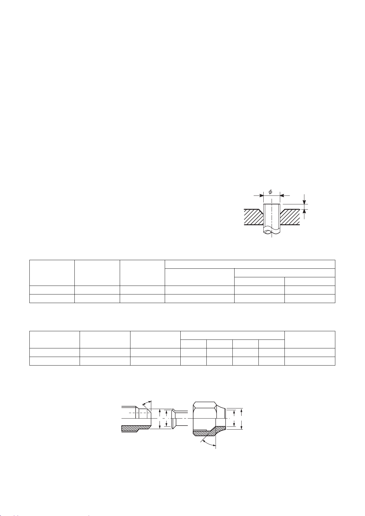
Flare and precautions
1) Cut a pipe.
Cut slowly with a pipe cutter so that the pipe is not distorted.
2) Remove burr and flaw.
A burr or flaw in a flare part may cause refrigerant leak. Remove carefully all the burrs, and clean up the
cut ends before installation.
3) Insert a flare nut.
4) Flare
Check that the clasps and copper pipe are clean. Flare
correctly using the clasp. Use a flare tool for R410A or the
conventional one. Flare processing dimension varies
depending on the flare tool type. When using the
conventional flare tool, use a gauge for size adjust me n t
to secure the A dimension.
Figure 2-2-1
Flare dimension
D
A
Table 2-2-3 Flare processing related dimension for R410A
Nominal
diameter
3/8 9.52 0.8 0 to 0.5 1.0 to 1.5 2.0 to 2.5
5/8 15.9 1.0 0 to 0.5 1.0 to 1.5 2.0 to 2.5
Outer diameter
(mm)
Wall thickness
(mm)
Flare tool for R410A
clutch type
Table 2-2-4 Dimension of flare for R410A and flare nut
Nominal
diameter
3/8 9.52 0.8 13.0 13.2 9.7 20 18
5/8 15.9 1.0 19.1 19.7 15.9 24.5 26
Outer diameter
(mm)
Wall thickness
(mm)
ABCD
Dimension (mm)
Figure 2-2-2 Relationship between flare nut and flare surface
45° - 46°
A (mm)
Conventional flare tool
Clutch type Butterfly-nut type
Flare nut width
(mm)
DCB A
43° - 45°
8
Page 10

Flare connecting procedure and precautions
1) Make sure that the flare and connecting portions do not have any flaw and dust.
2) Correctly align the flared surface and the connecting axis.
3) Tighten the flare with designated torque by means of a torque wrench. The tightenin g to rque fo r R4 10A is
the same as that for the conventional R22. If the torque is weak, gas leakage may occur. If it is too strong,
the flare nut may crack and may be made non-removable. When choosing the tightening toque, comply
with values designated by products. Table 2-2-5 shows reference values.
NOTE
When applying oil to the flare surface, be sure to use oil designated by the product. Us ing any other oil deteriorates
the lubricating oil, possibly causing the compressor to burn out.
Table 2-2-5 Tightening torque of flare for R410A (Reference values)
Nominal diameter Outer diameter (mm) Tightening torque N•m (kgf•m)
3/8 9.52 33 to 42 (3.3 to 14.2)
5/8 15.9 66 to 82 (6.8 to 8.2)
9
Page 11

2-3. Tools
2-3-1. Necessary tools
In Air to Water Heat Pump using R410A, the service port diameter of packed valve of the outd oor un it is change d
to prevent mixing of other refrigerant. To reinforce the pressure resistance, flare dimensions and opposite side
dimensions of flare nut (For Ø 12.7 copper pipe) of the refrigerant piping are lengthened.
Because the refrigerating machine oil is changed, mixing of oil may generate sludge, clog capillary, or cause other
problems. Accordingly, the tools to be used include:
• tools dedicated for R410A (Those that cannot be used for the conventional refrigerant, R22)
• tools dedicated for R410A, but can be also used for the conventional refrigerant, R22
• tools that can be used for the conventional refrigerant, R22.
The following table shows the tools dedicated for R410A and their interchangeability.
Tools dedicated for R410A (The following tools must be for R410A)
Tools whose specifications are changed for R410A and their interchangeability
R410A Air to Water Hear Pump
No. Tool to be used Usage
1 Flare tool Pipe flaring Yes *(Note 1) Yes
2
3 Torque wrench (For Ø15.9) Connection of flare nut Yes No No
4 Gauge manifold
5 Charge hose
6 Vacuum pump adapter Vacuum evacuating Yes No Yes
7
8 Refrigerant cylinder Refrigerant charge Yes No No
9 Leakage detector Gas leakage check Yes No Yes
10 Charging cylinder Refrigerant charge *(Note 2) No No
Copper pipe gauge for
adjusting projection margin
Electrical balance for
refrigerant charging
Flaring by conventional
flare tool
Evacuating, refrigerant
charge, run check, etc.
Refrigerant charge Yes No Yes
For R410A
Existence of new
equipment
installation
Conventional
equipment can be
used
Yes *(Note 1) *(Note 1)
Yes No No
Conventional refrigerant
Air to Water Heat Pump
installation
New equipment can be
used with conventional
refrigerant
* (Note 1) Flaring for R410A by using the conventional flare tool requires projection margin adjustment. This
adjustment requires copper pipe gauge or other instrument.
* (Note 2) A charging cylinder for R410A is currently under development.
General tools (Conventional tools are available)
In addition to the above dedicated tools, the following equipment also available for R22 is necessary as the general
tools.
1. Vacuum pump
Use this by attaching vacuum pump
adapter.
4. Reamer 9. Hole core drill (Ø65)
5. Pipe bender 10. Hexagon wrench
(Opposite side 4mm)6. Level vial
2. Torque wrench (For Ø6.35) 7. Screwdriver (+, –) 11. Tape measure
3. Pipe cutter 8. Spanner or Monkey wrench 12. Metal saw
Also prepare the following equipment for other work methods or run check.
1. Clamp meter 3. Insulation resistance meter
2. Thermometer 4. Electroscope
10
Page 12
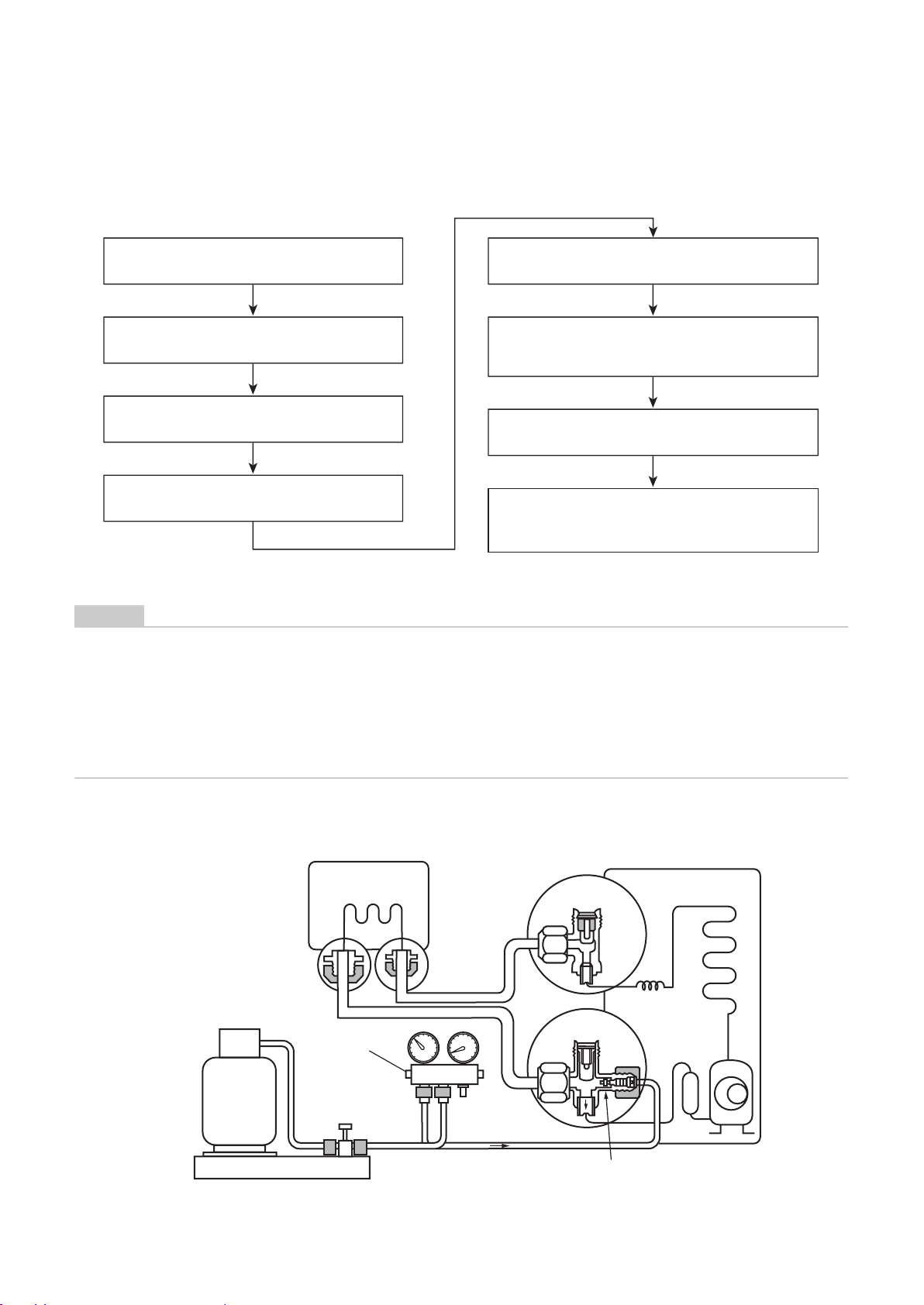
2-4. Recharging of refrigerant
Recharge, if necessary, the specified amount of new refrigerant according to the following procedure.
Recover the refrigerant, and check that no
refrigerant remains in the refrigerant cycle.
Connect the charge hose to packed valve service
port on the outdoor unit's gas side.
Connect the charge hose to the vacuum pump
adapter.
Open fully both packed valves on the liquid and
gas sides.
Open fully the handle of gauge manifold Lo, turn on the
vacuum pump, and then perform vacuum evacuating.
When the compound gauge's pointer indicates
-0.1 MPa (-76cmHg), close fully the handle Lo and turn
off the vacuum pump.
Let the equipment stay as it is for one to two minutes
and check that the compound gauge pointer does not
return.
Place the refrigerant cylinder to the electronic balance,
connect the connecting hose to the cylinder and the
connecting port of the electronic balance, and then
charge liquid refrigerant.
(For refrigerant charging, see the figure below)
NOTE
• Never charge refrigerant exceeding the specified amount.
• If the specified amount of refrigerant cannot be charged, charge it a little at a time while running refrigerant
recovery (pump down).
• Do not make additional charging.
An additional charge when refrigerant leaks changes the refriger ant composition in the refrigerant cycle,
causing the characteristics change of the Air to Water Heat Pump or excessive high pressure in the refrigerant
cycle with more than the specified amount of refrigerant charged. This may cause burst or an injury.
Fig. 2-4-1 Configuration of refrigerant charging
(Hydro unit)
Refrigerant cylinder (with siphon)
Check valve
CloseOpen
Open/close valve
for charging
Electronic balance for refrigerant charging
11
(Outdoor unit)
Open
Open
Service port
Page 13
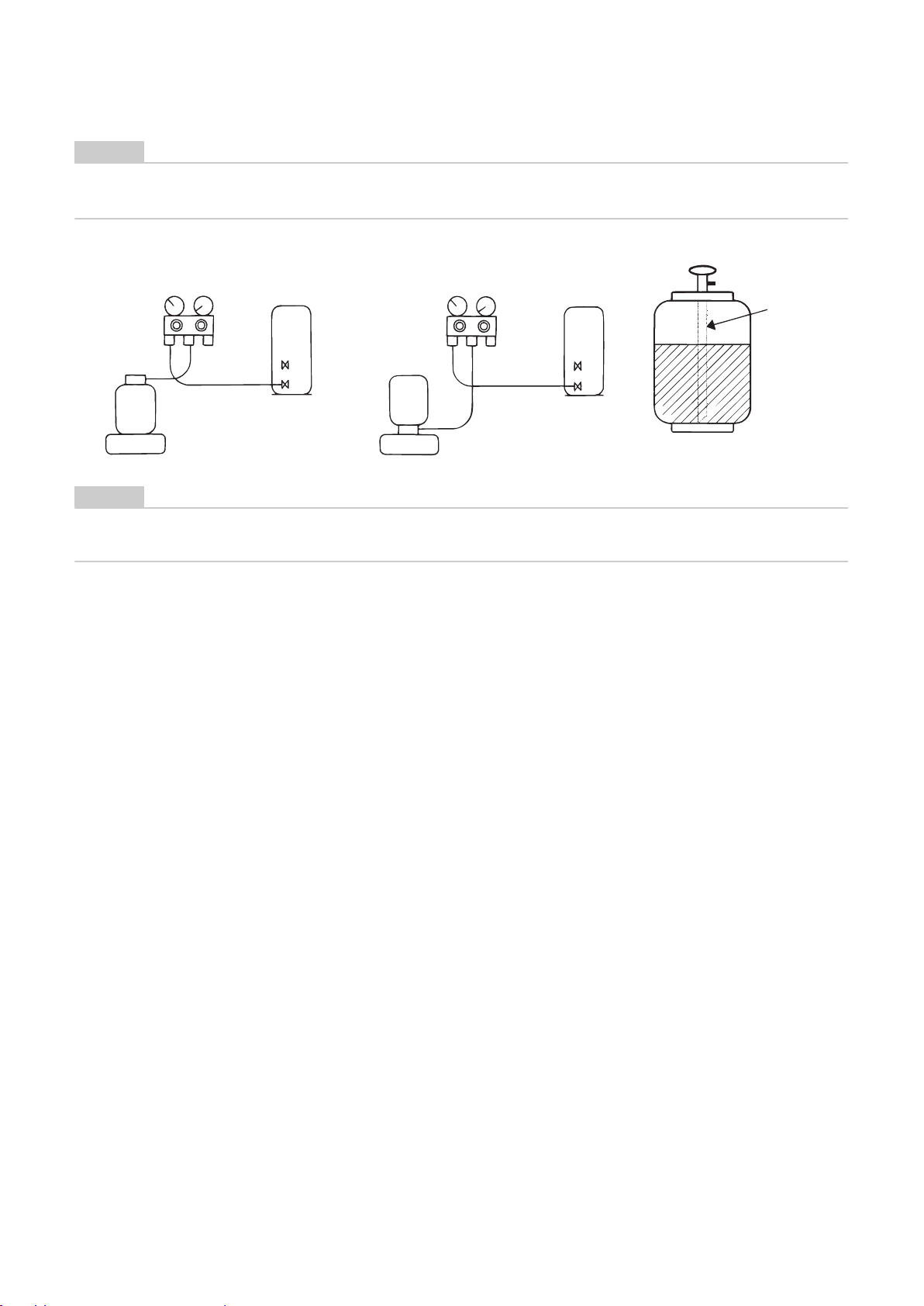
NOTE
• Make sure that the setting is appropriate so that liquid can be charged.
• A cylinder with siphon enables liquid to be charged without the cylinder turned upside down.
[Cylinder without siphon]
Gauge manifold
Outdoor unit
Siphon pipe
Gauge manifold
Refrigerant
cylinder
Electronic balance
[Cylinder with siphon]
Outdoor unit
Refrigerant
cylinder
Electronic balance
NOTE
• Because R410A is HFC mixed refrigerant, charging with gas changes the charged refrigerant composition,
causing the equipment characteristics to change.
12
Page 14

2-5. Brazing of pipes
2-5-1. Materials of brazing
Silver brazing metal
Silver brazing metal is an alloy mainly composed of
silver and copper.
It uses iron, copper, or copper alloy, and is relatively
expensive though it excels in soldering.
Phosphor bronze brazing metal
Phosphor bronze brazing metal is generally used to
join copper or copper alloy.
Low temperature brazing metal
Low temperature brazing metal is generally called
solder, and is an alloy of tin and lead. Do not u se it for
refrigerant piping because its adhesive capacity is low.
NOTE
• Phosphor bronze brazing metal tends to react with
sulfur, producing a fragile compound water solution.
This may cause gas leakage. Therefore, use other
type of brazing metal at a hot spring resort or similar
place, and coat the surface with coatings.
• To braze the pipe again while performing service
work, use the same type of brazing metal.
2-5-2. Flux
Type of flux
• Non-corrosive flux
It is generally a compound of borax and boric acid.
It is effective when brazing temperature is higher
than 800 °C.
• Active solvent
Most of this type of flux is generally used for silver
brazing.
It features the increase of oxide film while moving the
capability to the borax-boric acid compound to add
compounds such as potassium fluoride, potassium
chloride, or sodium fluoride.
Piping materials for brazing and brazing
metal / flux
Piping material
Copper - Copper Phosphor copper Do not use
Copper - Iron Silver Paste flux
Iron - Iron Silver Vapour flux
NOTE
• Do not enter flux into the refrigerant cycle.
• If chlorine contained in the flux remains within the
pipe, the lubricating oil deteriorates. Because of
this, use a flux that does not contain chlorine.
• When adding water to the flux, use water that does
not contains chlorine. (e.g. distilled water or ionexchange water)
• Remove the flux after brazing.
Brazing metal to be
used
Flux to be used
Why flux is necessary
• Removing all the oxide film and any foreign matter
on the metal surface assists the flow of brazing
metal.
• Flux prevents the metal surface from being oxidized
in the course of brazing.
• Reducing the brazing metal's surface tension
enables the brazing metal to adhere for better metal
processing.
Characteristics of flux
• The activation temperature of flux matches the
brazing temperature.
• A wide effective temperature range makes flux hard
to carbonize.
• It is easy to remove slag after brazing.
• The corrosive action to the treate d metal and brazing
metal is minimum.
• The good performance of flux gives no harm to a
human body.
Since flux works in a complicated manner as
described above, select an appropriate type of flux
according to metal treatment type , brazing metal and
brazing method, or other conditions.
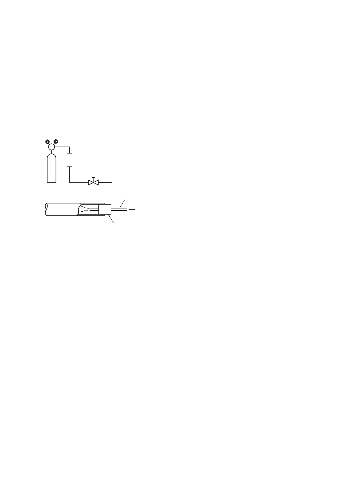
2-5-3. Brazing
Brazing must be performed by a person qualified and
experienced with theoretical knowledge since the
operation requires sophisticated techniques.
Perform brazing while flowing dry nitrogen gas (N2) to
prevent oxide film from forming during brazing
application to the inside of the pipe.
NOTE
• Never use gas other than nitrogen gas.
Brazing method to prevent oxidation
1) Attach a reducing valve and a flow meter to the
nitrogen cylinder.
2) Use a copper pipe to direct the piping material,
and attach the flow meter to the balance.
3) Apply a mark to the clearance between the
piping material and the copper pipe filled with
nitrogen to prevent the back flow of the
nitrogen gas.
4) If the nitrogen gas flows out, be sure to keep
open the piping end.
13
Page 15
5) Use the reducing valve to adjust the nitrogen
gas flow speed to 0.05 m
(0.2 kgf/cm
2
).
3
/hour or 0.02 MPa
6) After the steps above, keep the nitrogen gas
flowing until the pipe cools down to a certain
extent. (Temperature where the pipe is cool
enough to be touched by hands)
7) Remove the flux completely after brazing.
Fig 2-5-1
Prevention of oxidation during brazing
Flow meter
M
Stop valve
Nitrogen gas cylinder
From nitrogen cylinder
Pipe
Nitrogen gas
Robber plug
14
Page 16

3 Specifications
Unit name Hydro unit HWS-803XWHM3-E, 803XWHT6-E, 803XWHD6-E, 803XWHT9-E
Heating capacity *1 (kW) 8.0
Cooling capacity *2 (kW) 6.0
Variable range of compressor frequency 10 - 70 Hz
Power source Single phase 50Hz 220 - 230V
Operation mode Heating Cooling
Electric characteristic *1 *2 Hydro unit Current (A) 0.98 0.46
Operating noise *1 *2 *4 Hydro unit (dB(A)) 29 29
Coefficient of performance *1 *2 4.40 2.82
Hydro unit Outer dimension Height (mm) 925
Outdoor unit Outer dimension Height (mm) 890
Refrigerant piping Connection method Flare connection
Refrigerant Refrigerant name R410A
Water piping Pipe diameter R1 1/4
Operating temperature range Hydro unit (°C) 5-32
Operating humidity range Hydro unit (%) 15-85
Wiring connection Power wiring 3 wires: including ground line (Outdoor unit)
*1 Heating performance measurement conditions: outside air temperature 7 °C, water supply temperature 30 °C, outlet temperature 35 °C, refrigerant piping length 7.5 m (no height
difference).
*2 Cooling performance measurement conditions: outside air temperature 35 °C, water s upply temperature 12 °C, outlet temperature 7 °C, refrigerant piping length 7.5 m (no height
difference).
*3 • The remote controller should be shipped with the hydro unit.
• Use two 1.5-meter wires to connect the hydro unit with the remote controller.
*4 The outdoor unit operating noise is measured at the point of 1m away from the unit back surface centre and 1m high from the ground. The hydro unit operating noise is measu r ed at the
point of 1m away from the unit front surface centre.
The value of the operating noise varies depending on room structure where the unit is installed.
*5 Do not leave the hydro unit at 5 °C or below.
*6 Check the water piping for leakage under the maximum operating pressure.
Outdoor unit HWS-803H-E
Power (kW) 0.101 0.097
Outdoor unit Current (A) 7.64 8.90
Total Starting current (A) 8.62 9.36
Outdoor unit (dB(A)) 49 49
Net weight (kg) 50
Color Silky shade (Munsell 1Y8.5/0.5)
Remote controller
Outer dimension *3
Circulating pump Motor output (W) 125 (MAX)
Heat exchanger Plate-type heat exchange
Net weight (kg) 63
Color Silky shade (Munsell 1Y8.5/0.5)
Compressor Motor output (W) 1400
Fan motor Standard air capacity (m3/min) 50.0
Hydro unit Liquid Ø9.52
Outdoor unit Liquid Ø9.52
Maximum length (m) 30
Maximum chargeless length (m) 30
Maximum height difference (m) ±30
Minimum length (m) 5
Charge amount (kg) 1.8
Maximum length (m) None (Need the flow rate 13 /min or more)
Maximum height difference (m) ±7
Maximum working water pressure (kPa) 300
Outdoor unit (°C) -20-43
Outdoor unit (%) 15-100
Connecting line 4 wires: including ground line
Power factor (%) 91.5 91.7
Power (kW) 1.719 2.033
Power factor (%) 97.8 99.3
Width (mm) 525
Depth (mm) 355
Height (mm) 120
Width (mm) 120
Depth (mm) 16
Flow rate (L/min) 22.9 17.2
Type Non-self-suction centrifugal pump
Width (mm) 900
Depth (mm) 320
Type Twin rotary type with DC-inverter variable speed control
Model DA220A2F-22L
Motor output (W) 60
Gas Ø15.9
Gas Ø15.9
15
Page 17

Unit name Hydro unit HWS-1403XWHM3-E, 1403XWHT6-E, 1403XWHD6-E, 1403XWHT9-E
Heating capacity *1 (kW) 11.2 14.0
Cooling capacity *2 (kW) 10.0 11.0
Variable range of compressor frequency 10 - 60Hz 10 - 70 Hz
Power source Single phase 50Hz 220 - 230V
Operation mode Heating Cooling Heating Cooling
Electric characteristic *1 *2 Hydro unit Current (A) 0.63 0.61 0.67 0.63
Operating noise *1 *2 *4 Hydro uni t (dB(A)) 29 29 29 29
Coefficient of performance *1 *2 4.77 2.84 4.50 2.70
Hydro unit Outer dimension Height (mm) 925
Outdoor unit Outer dimension Height (mm) 1340
Refrigerant piping Connection method Flare connection
Refrigerant Refrigerant name R410A
Water piping Pipe diameter R1 1/4
Operating temperature range Hydro unit (°C) 5-32
Operating humidity range Hydro unit (%) 15-85
Wiring connection Power wiring 3 wires: including ground line (Outdoor unit)
*1 Heating performance measurement conditions: outside air temperature 7 °C, water supply temperature 30 °C, outlet temperature 35 °C, refrigerant piping length 7.5 m (no height
difference).
*2 Cooling performance measurement conditions: outside air temperature 35 °C, water s upply temperature 12 °C, outlet temperature 7 °C, refrigerant piping length 7.5 m (no height
difference).
*3 • The remote controller should be shipped with the hydro unit.
• Use two 1.5-meter wires to connect the hydro unit with the remote controller.
*4 The outdoor unit operating noise is measured at the point of 1m away from the unit back surface centre and 1m high from the ground. The hydro unit operating noise is measur ed at the
point of 1m away from the unit front surface centre.
The value of the operating noise varies depending on room structure where the unit is installed.
*5 Do not leave the hydro unit at 5 °C or below.
*6 Check the water piping for leakage under the maximum operating pressure.
Outdoor unit HWS-1103H-E HWS-1403H-E
Power (kW) 0.135 0.130 0.145 0.135
Outdoor unit Current (A) 9.94 14.88 13.37 17.47
Total Starting current (A) 10.57 15.49 14.04 18.10
Outdoor unit (dB(A)) 49495151
Net weight (kg) 54
Color Silky shade (Munsell 1Y8.5/0.5)
Remote controller
Outer dimension *3
Circulating pump Motor output (W) 190 (MAX)
Heat exchanger Plate-type heat exchange
Net weight (kg) 93
Color Silky shade (Munsell 1Y8.5/0.5)
Compressor Motor output (W) 2500
Fan motor Stand ard air capacity (m3/min) 103.0
Hydro unit Liquid Ø9.52
Outdoor unit Liquid Ø9.52
Maximum length (m) 30
Maximum chargeless length (m) 30
Maximum height difference (m) ±30
Minimum length (m) 5
Charge amount (kg) 2.7
Maximum length (m) None (Need the flow rate 17.5 /min or more)
Maximum height difference (m) ±7
Maximum working water pressure (kPa) 300
Outdoor unit (°C) -20-43
Outdoor unit (%) 15-100
Connecting line 4 wires: including ground line
Power factor (%) 93.2 92.7 94.0 93.2
Power (kW) 2.2153.392.9653.945
Power factor (%) 96.9 99.1 96.4 98.1
Width (mm) 525
Depth (mm) 355
Height (mm) 120
Width (mm) 120
Depth (mm) 16
Flow rate (L/min) 32.1 28.9 40.1 31.5
Type Non-self-suction centrifugal pump
Width (mm) 900
Depth (mm) 320
Type Twin rotary type with DC-inverter variable speed control
Model DA422A3F-25M
Motor output (W) 100 × 2
Gas Ø15.9
Gas Ø15.9
16
Page 18
Unit name Hydro unit HWS-1403XWHM3-E, 1403XWHT6-E, 1403XWHD6-E, 1403XWHT9-E
Heating capacity *1 (kW) 11.2 14.0 16.0
Cooling capacity *2 (kW) 10.0 11.0 13.0
Variable range of compressor frequency 10 - 60Hz 10 - 60 Hz 10 - 70 Hz
Power source 3 phase 50Hz 380 - 400V
Operation mode Heating Cooling Heating Cooling Heating Cooling
Electric characteristic *1 *2 Hydro unit Current (A) 0.63 0.61 0.67 0.63 0.69 0.66
Operating noise *1 *2 *4 Hydro unit (dB(A)) 29 29 29 29 29 29
Coefficient of performance *1 *2 4.69 2.84 4.36 2.70 4.30 2.71
Hydro unit Outer dimension Height (mm) 925
Outdoor unit Outer dimension Height (mm) 1340
Refrigerant piping Connection method Flare connection
Refrigerant Refrigerant name R410A
Water piping Pipe diameter R1 1/4
Operating temperature range Hydro unit (°C) 5-32
Operating humidity range Hydro unit (%) 15-85
Wiring connection Power wiring 5 wires: including ground line (Outdoor unit)
*1 Heating performance measurement conditions: outside air temperature 7 °C, water supply temperature 30 °C, outlet temperature 35 °C, refrigerant piping length 7.5 m (no height
difference).
*2 Cooling performance measurement conditions: outside air temperature 35 °C, water s upply temperature 12 °C, outlet temperature 7 °C, refrigerant piping length 7.5 m (no height
difference).
*3 • The remote controller should be shipped with the hydro unit.
• Use two 1.5-meter wires to connect the hydro unit with the remote controller.
*4 The outdoor unit operating noise is measured at the point of 1m away from the unit back surface centre and 1m high from the ground. The hydro unit operating noise is measu r ed at the
point of 1m away from the unit front surface centre.
The value of the operating noise varies depending on room structure where the unit is installed.
*5 Do not leave the hydro unit at 5 °C or below.
*6 Check the water piping for leakage under the maximum operating pressure.
Outdoor unit HWS-1103H8(R)-E HWS-1403H8(R)-E HWS-1603H8(R)-E
Power (kW) 0.135 0.130 0.145 0.135 0.150 0.140
Outdoor unit Current (A) 4.03 5.65 5.23 6.50 5.95 7.50
Total Starting current (A) 4.66 6.26 6.06 7.13 4.26 8.16
Outdoor unit (dB(A)) 495051515252
Net weight (kg) 54
Color Silky shade (Munsell 1Y8.5/0.5)
Remote controller
Outer dimension *3
Circulating pump Motor output (W) 190 (MAX)
Heat exchanger Plate-type heat exchange
Net weight (kg) 93
Color Silky shade (Munsell 1Y8.5/0.5)
Compressor Motor output (W) 2500
Fan motor Standard air capacity (m3/min) 103.0
Hydro unit Liquid Ø9.52
Outdoor unit Liquid Ø9.52
Maximum length (m) 30
Maximum chargeless length (m) 30
Maximum height difference (m) ±30
Minimum length (m) 5
Charge amount (kg) 2.7
Maximum length (m) None (Need the flow rate 17.5 /min or more)
Maximum height difference (m) ±7
Maximum working water pressure (kPa) 300
Outdoor unit (°C) -20-43
Outdoor unit (%) 15-100
Connecting line 4 wires: including ground line
Power factor (%) 93.2 92.7 94.0 93.2 94.5 92.3
Power (kW) 2.255 3.39 3.065 3.945 3.570 4.660
Power factor (%) 81.187.084.988.087.090.0
Width (mm) 525
Depth (mm) 355
Height (mm) 120
Width (mm) 120
Depth (mm) 16
Flow rate (L/min) 32.128.940.131.545.837.3
Type Non-self-suction centrifugal pump
Width (mm) 900
Depth (mm) 320
Type Twin rotary type with DC-inverter variable speed control
Model DA422A3F-27M
Motor output (W) 100 × 2
Gas Ø15.9
Gas Ø15.9
17
Page 19
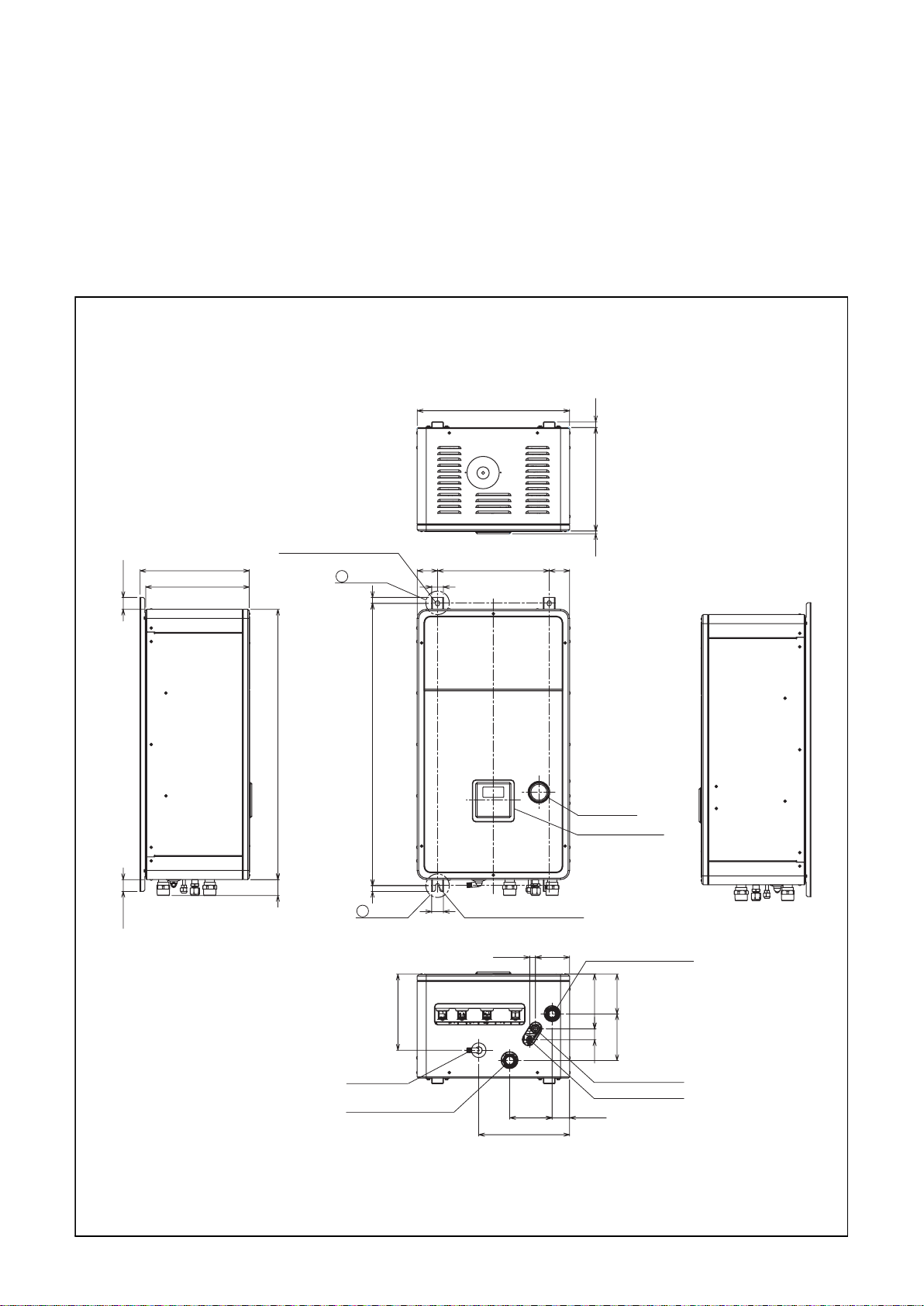
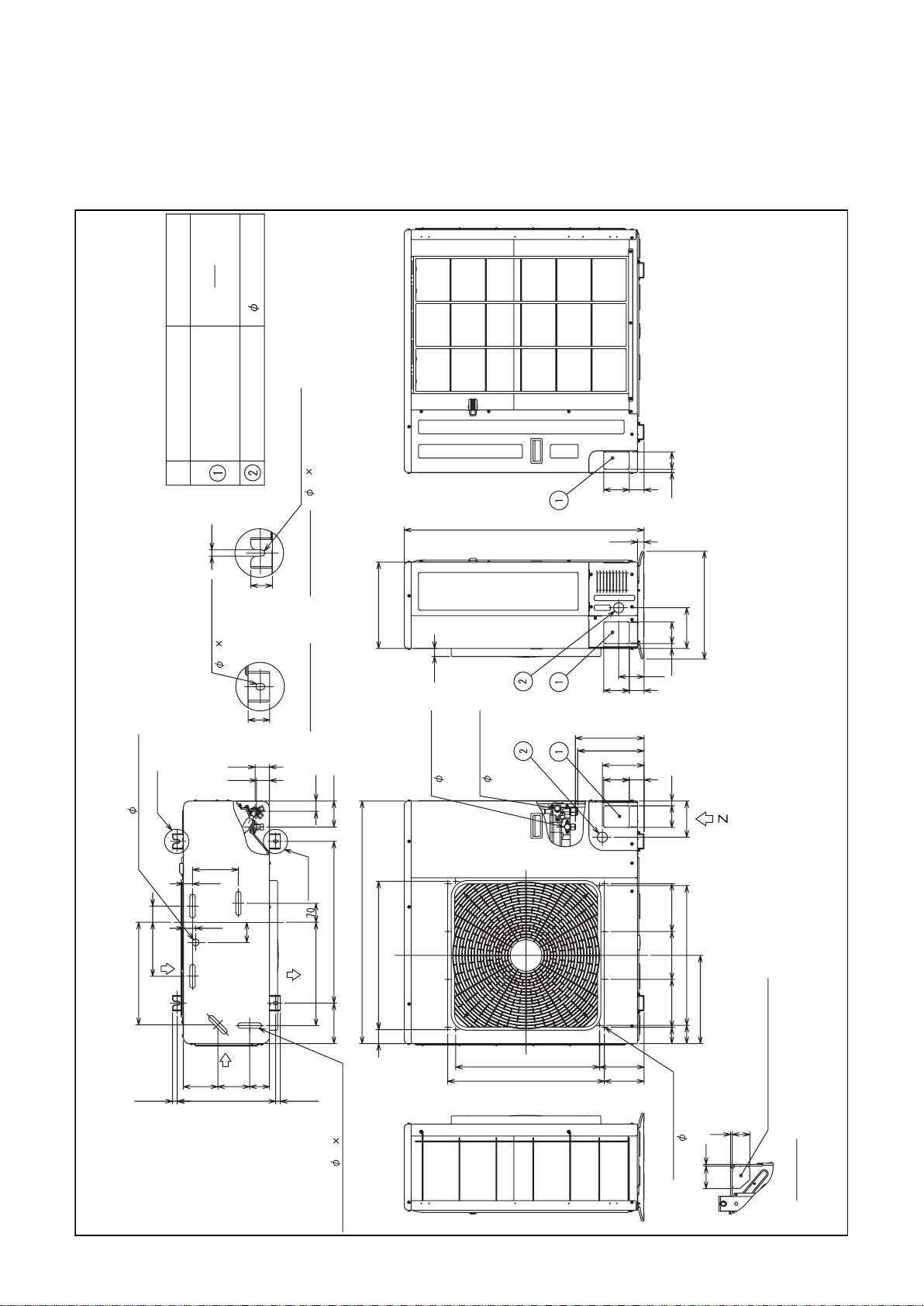
4 Outside Drawing
4-1. Hydro unit
HWS-803XWHM3-E, 803XWHT6-E, 803XWHD6-E, 803XWHT9-E
HWS-1403XWHM3-E, 1403XWHT6-E, 1403XWHD6-E, 1403XWHT9-E
40.540.5
371.5
355
2-dia.12x17 long hole
(for dia.8-10 anchor bolt)
B leg part
92554
72.5 72.5
Anchor bolt
40
2020
960
Anchor bolt long hole pitch
525
380
long hole pitch
19.5
352
9
Manometer
Remote controler
A leg part
Drain nipple
Water inlet
connecting pipe 1 1/4"
40
259
2-dia.12x17 U-shape hole
(for dia.8-10 anchor bolt)
309.5
18
11619.5
Hot water outlet
connecting pipe 1 1/4"
135.5
186.5
158
37.5
Gas line dia.15.88
Liquid line dia.9.52
59.5144.5
Page 20
4-2. Outdoor unit
HWS-803H-E
Name Description
Refrigerant piping outlet
Indoor and outdoor
connecting line outlet
Power source intake hole 38 knockout hole
Mounting bolt hole
( 12 17 U-shape hole)
64
55
95
12
12
Mounting bolt hole
( 12 17 long hole)
54
48
Portion B
Drain hole ( 25 burring hole)
60
200
Air inlet
380
170
34
46
75
40
40
Air outlet
Details of portion B
Details of portion A
39
Portion A
383
96
600
150
320
900
550
52
30
Refrigerant gas
Refrigerant liquid
connection
connection
( 9.5 flare)
890
( 15.9 flare)
255
247
24
400
151
80
18
94
95
55
155
55
95
18
80
135
178
178
518
327
178
60
68
17.5
Air inlet
128
365
118
534
74
17.5
5-Drain hole ( 20 88 burring hole)
581
165
148
(12- 3 embossed)
Optional mounting hole
7
7
83
Knockout for lower part of piping
65
Z arrow view
19
Page 21
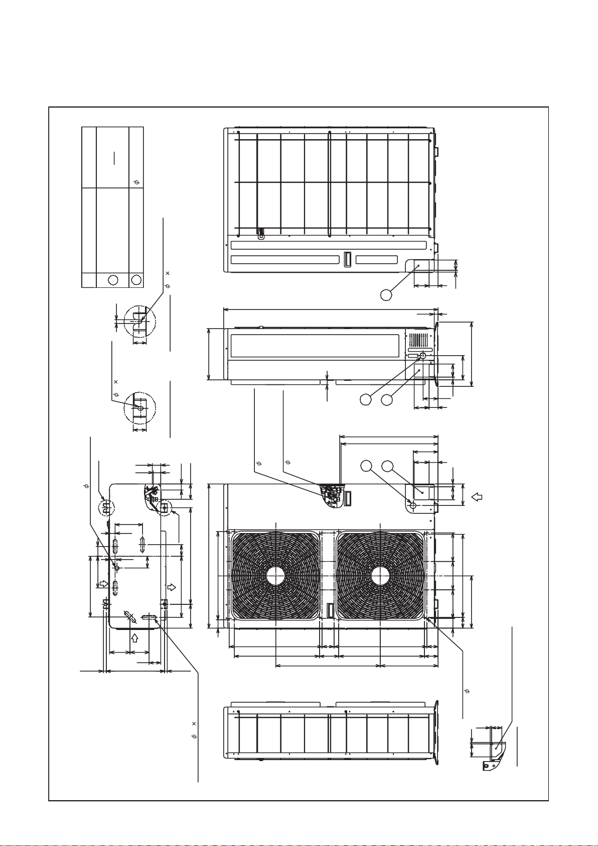
HWS-1103H-E, 1403H-E, 1103H8(R)-E, 1403H8(R)-E, 1603H8(R)-E
Description
38 knockout hole
Name
Refrigerant piping outlet
Indoor and outdoor
connecting line outlet
Power source intake hole
2
1
12
40
Mounting bolt hole
( 12 17 long hole)
40
Portion B
Mounting bolt hole
( 12 17 U-shape hole)
Details of portion B
Details of portion A
54
48
39
64
9555
1
1340
320
30
( 15.9 flare)
Refrigerant gas connection
( 9.5 flare)
96
Refrigerant liquid connection
1
2
613
605
1
2
12
24
400
151
80
18
94
55
95
155
55
95
1880
Z
135
Drain hole ( 25 burring hole)
60
200
Air inlet
380
17.5
170
34
46
Air inlet
128
75
118
74
Portion A
70
600
900
Air outlet
383
150
52 550
17.5 365
5-Drain hole ( 20 88 burring hole)
53412153485
360 655
518
327
178 178 178
60
68
70 581 74 581
(24- 3 embossed)
Optional mounting hole
7
83
Knockout for lower part of piping
65
7
Z arrow view
20
Page 22
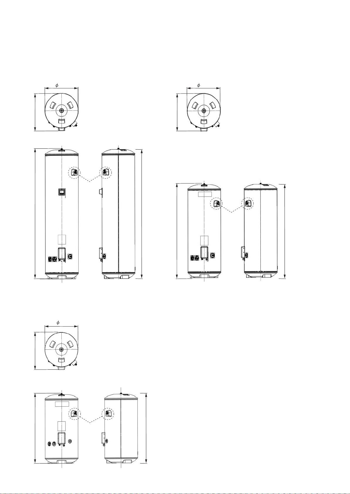
4-3. Hot water cylinder
HWS-3001CSHM3-E(-UK)
550
5952066.6
Specification
for UK only
2040
HWS-2101CSHM3-E(-UK)
550
5951497.6
Specification
for UK only
1474
HWS-1501CSHM3-E(-UK)
550
5951114
Specification
for UK only
1090
21
Page 23
5 Wiring Diagram
5-1. Hydro Unit
Color identification
BLK : BLACK
BRW : BROWN
GRY : GRAY
PNK : PINK
WHI : WHITE
WHI WHI
YEL
5
5251
WPM
*See DIP SW13_1
BLU
55
3
4
5
2WV
BLU : BLUE
GRN : GREEN
ORN : ORANGE
RED : RED
YEL : YELLOW
BRW
WARNING
CAUTION
YEL
BLU
BRW
WHI
WHI
RED
WHI
RED
WHI
YEL
5
8
59
56
5
7
BH 3WV
(2-wire spring return)
WHI
YEL
RED
59
57
8
5
3WV
(3-wire SPST type)
(3-wire SPDT type)
TB 05
Type 1
TB 05
Type 2
Type 3
9
9
787
6
55
4
3
2
11
3
3
2
11
Perform the grounding from the
earth terminal in the terminal
block of the outdoor unit.
Electric shock may happen.
Don't touch the electric parts.
CN10
(WHI)
CR10
CR11
CR12
CR13
CN01
(WHI)
F01 (5A)
PNK
RED
41
42
MIXV
(3-wire SPDT type)
PNK
RED
41
42
MIXV
(3-wire SPST type)
4
43
WHI
WHI
RY
11
3
RY
10
RY
13
ORN
44
ORN
4
4
RY
12
Relay
p.c.board
(MCC-1431)
WPM
TB 04
Type 1
TB 04
Type 2
CN02
(WHI)
A2
LNNL
(HWS-AMS11E)
55
4
3
2
11
RY
A1
05
Remote
controller
AB
GRY
4
3
2
BLK
*Option
Remote
controller
(HWS-AMS11E)
AB
TB 07
A
7
B
7
WHI
RED
BLU
ORN
GRN
BRW
BLU
BRW
RED
WHI
YEL
WHI
RED
2
1
2
1
WHI
GRY
BLK
BLK
2
3
1
1
2
2
3
1
1
CN41
CN203
(YEL)
(BLU)
6
5
5
4
4
CN501
(YEL)
3
3
2
2
1
1
313
CN603
(YEL)
1
313
CN601
(RED)
1
7
7
5
5
3
1
1
CN602
(WHI)
RY601RY600RY603 RY602
RY604
CN604
(BLU)
5
3
7
5
3
7
L
WHI
YE
RED
5
7
RY
06
468
2
PNK
ORN
RED
THOTWOTWITC
LPS
3
4
1
2
3
4
2
3
4
2
3
4
2
BLK
BLK
BLK
BLK
BLK
BLK
1
1
CN204
(BRW)
3
2
3
2
111
1
2
1
1
CN206
CN205
(RED)
P.C.board
(MCC-1511)
(WHI)
WHI
BLK
RED
3
2
2
2
22
3
34
1
CN207
CN212
(BLU)
(WHI)
1
SW01
SW02
ON
12 43
SW10 SW11 SW12 SW13
ON
CN605
(YEL)
1
1
BLK
RY
01
RY606RY605
3
1
3
1
WHI
ORN
A2
6
RY
02
A1
4
WHI WHI
ON
1234 1234 123 41234
SW06
ON
CN606
(BLU)
*
1
1
WHI
6
487
1
RY607
3
3
A1
RY
04RY03
A2
ON21ON
SW07
PNK
*Option
TTW
TFI
AB
TB 06
6
C
D
A
6
6
6
B
BRW
BRW
RED
2
3
1
1
2
2
3
1
1
CN213
CN214
(WHI)
(WHI)
SW14
OFF
ON
CN305
CN100
(GRN)
(WHI)
5
3
3
1
1
33
1
WHI
RED
GRY
Symbol
WPM
3WV
2WV 2-way valve (local)
MIXV
BH
RY01~RY06
LPS
RED
CN208
(BLU)
CN209
(GRN)
CN210
(RED)
CN211
(BLK)
CN200
(RED)
CN201
(WHI)
CN202
(YEL)
CN102
(WHI)
CN101
(WHI)
F100
Fuse
T5A
250V~
1
*
Water pump motor
3-way valve (local)
Mixing valve (local)
Booster heater
Relay01~Relay06
Low pressure sensor
Heater AC230V, 3kWBackup heater1, 2, 3
GRN
1
1
GRN
2
2
2
2
GRN
3
3
3
3
GRN
414
414
PJ20
GRN
1
1
GRN
2
2
2
2
GRN
3
3
3
3
GRN
414
414
PJ20
YEL
1
1
YEL
2
2
2
2
YEL
3
3
3
3
YEL
414
414
PJ17
YEL
1
1
YEL
2
2
2
2
YEL
3
3
3
3
YEL
414
414
PJ17
YEL
7
1
1
GRN
2
2
RED
33
1
1
BLK
11
BLK
22
3
3
BLK
11
BLK
323
BRW
1
1
BRW
2
2
RED
3
3
RED
4
4
ORN
5
5
ORN
6
6
WHI
11
WHI
33
BLK
P100
HWS-803XWHT6-E : Installed
HWS-1403XWHT6-E : Installed
HWS-803XWHD6-E : Installed
HWS-1403XWHD6-E : Installed
HWS-803XWHT9-E : Installed
HWS-1403XWHT9-E : Installed
HWS-803XWHM3-E : Not installed
HWS-1403XWHM3-E : Not installed
Parts name
Relay
p.c.board
(MCC-1217)
Relay
p.c.board
(MCC-1217)
Photocoupler input
p.c.board
(MCC-1214)
Photocoupler input
p.c.board
(MCC-1214)
RY
2
8
01
11
Pressure switch
4.15MPa
Thermal protector
(auto)
Symbol
TC
TWI
TWO
THO
TTW
TFI
TB
4
K1
3
2
K2
1
TB1
4
K1
3
2
K2
1
TB1
3
2
1
TB1
3
2
1
TB1
2
Flow switch
75 5
Transformer
1
HWS-803XWHT6TR : Installed
*
HWS-1403XWHT6TR : Installed
HWS-1403XWHT9TR : Installed
HWS-803XWHM3TR : Not installed
HWS-1403XWHM3TR : Not installed
Parts name
Water heat exchanger temperature sensor
Water heat exchanger inlet temperature sensor
Water heat exchanger outlet temperature sensor
Backup heater outlet temperature sensor
Hot water cylinder temperature sensor
Floor heating inlet temperature sensor
Terminal block
*Option p.c.board
Boiler control O/P
Alerm O/P
Compressor operation
O/P
Defrost O/P
Emergency stop I/P
Cooling thermostat I/P
Heating thermostat I/P
1. The one-dot chain line indicates
wiring at the local site, and the
dashed line indicates accessories
sold separately and service wires,
respectively.
2.
, and indicates the terminal
board and the numberals ndicate the
terminal numbers.
indicates P.C. board.
3.
* Be sure to fix the electric
parts cover surely with screws.
(Otherwise water enters into the box
resulting in malfunction.)
WHI
RED
12111
3
12
Power supply
220 - 230V~ 50Hz
or
380 - 400V~ 50Hz
TB 03
GRY
TB 01
3
Outdoor unit
BRW
BLU
12
33
12
Hot water cylinder
1L1
3L2
4T2
2T1
BLU
BRW
F1 F2
BRW
N
L
Power supply
220 - 230V~ 50Hz
RY05
BLU
F1, F2
Fuse
AC250V
T30A
YEL/GRN
*Option
5L3
1L1
3L2
RY02
6T3
4T2
2T1
GRY
BRW
BLU
F3F4F6F5F8
F7
BLU
BLK
BLU
BRW
L3
L1L2
Power supply
380 - 400V 3N~ 50Hz
1
L12L3
2T1
BLU
GRY
N
Thermal protector
(Single operation)
95 5
Thermal protector
(Single operation)
95 5
5L3
6T3
4T2
BLK
BLU
F3~8
Fuse
AC250V
T30A
TB 02
Thermal protector
(Single operation)95 5
RY04
BLU
Backup heater 1
Backup heater 2
Backup heater 3
HWS-803XWHT9-E
HWS-1403XWHT9-E
HWS-1403XWHT9TR
RY02
4T22T1 6T3
BLU
BRW
F5
F3 F6
F4
BLK
BLU
BRW
Power supply
380 - 400V 3N~ 50Hz
3L51L12L3
BLK
1L2
L
Thermal protector
(Single operation)
Thermal protector
(Single operation)
1L1 3L2
2T1 4T2
F3~6
Fuse
AC250V
T30A
BLU
L3
95 5
95 5
5L3
RY04
6T3
BLU
TB 02
N
Backup heater 1
Backup heater 2
HWS-803XWHT6-E
HWS-1403XWHT6-E
HWS-803XWHT6TR
HWS-1403XWHT6TR
5L31L1 3L2
6T32T1 4T2
BLU
BRW
F3
F4
BLU
BRW
LN
Power supply
220 - 230V~ 50Hz
Thermal protector
(Single operation)
95 5
RY02
F3,F4
Fuse
AC250V
T30A
TB 02
Backup heater 1
HWS-803XWHM3-E
HWS-1403XWHM3-E
HWS-803XWHM3TR
HWS-1403XWHM3TR
RY02
4T22T1 6T3
BLU
BRW
F5
F3 F6
F4
BLU
BRW
Power supply
220 - 230V 3~ 50Hz
3L51L12L3
BLK
1L2
BLK
BLU
L
Thermal protector
(Single operation)
95 5
Thermal protector
(Single operation)
95 5
1L1 3L2
2T1 4T2
F3~6
Fuse
AC250V
T30A
TB 02
L3
5L3
6T3
BLU
Backup heater 1
Backup heater 2
RY04
HWS-803XWHD6-E
HWS-1403XWHD6-E
22
Page 24
5-2. Outdoor Unit (Single phase Type)
HWS-803H-E, HWS-1103H-E, HWS-1403H-E
Compressor
Fan motor
Pulse motor valve coil
Discharge temperature sonsor
Suction temperature sensor
Heat exchange sensor 1
Heat exchange sensor 2
Outdoor temperature sensor
Linetilter
4-way valve coil
Compressor case thermostat
Fuse 25 A, 250 VAC
Fuse 10A, 250 VAC
Reactor
Upper
RWB
(White)
White)
(
Symbol Item name
White)
(
20SF
4F
Control board
an optional accessory or service wiring.
1. indicates a terminal plate. The number inside indicates the terminal number.
2. The double-dashed line indicates a local wiring while the dashed line indicates
3. indicates a printed board.
4. For the hydro unit circuit, see the hydro unit wiring diagram.
220-230V
WhiteRed
50Hz
single phase
Power supply
Earth
screw
WR B
G
Hydro unit
valve
4-way
Earth screw
Outdoor unit
coil
Earth screw
(White)
(Blue)
HMS-1103,
1403H-E only
(Yellow)
input
External
White)
(
23
power
Operating
White)
(
White)
Yellow)
(
(
(White)
White)(White)(White)
(
Page 25
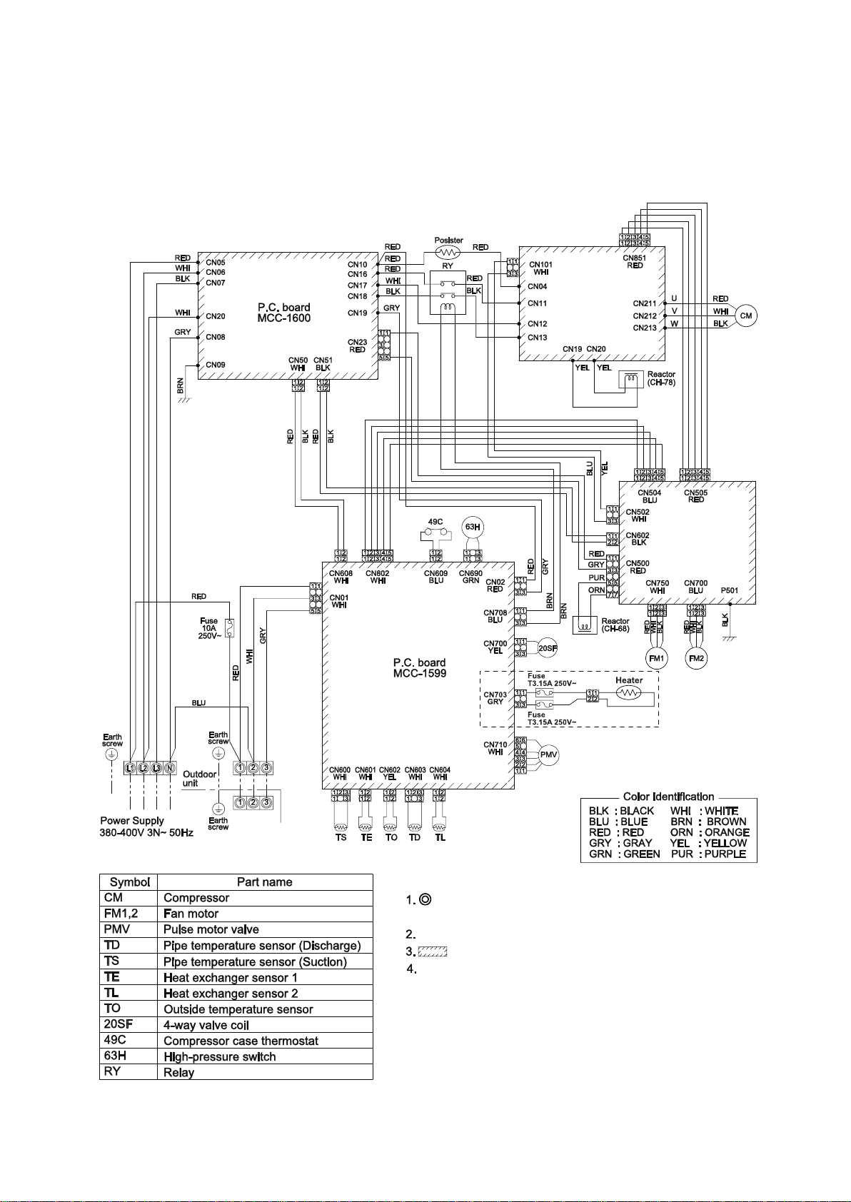
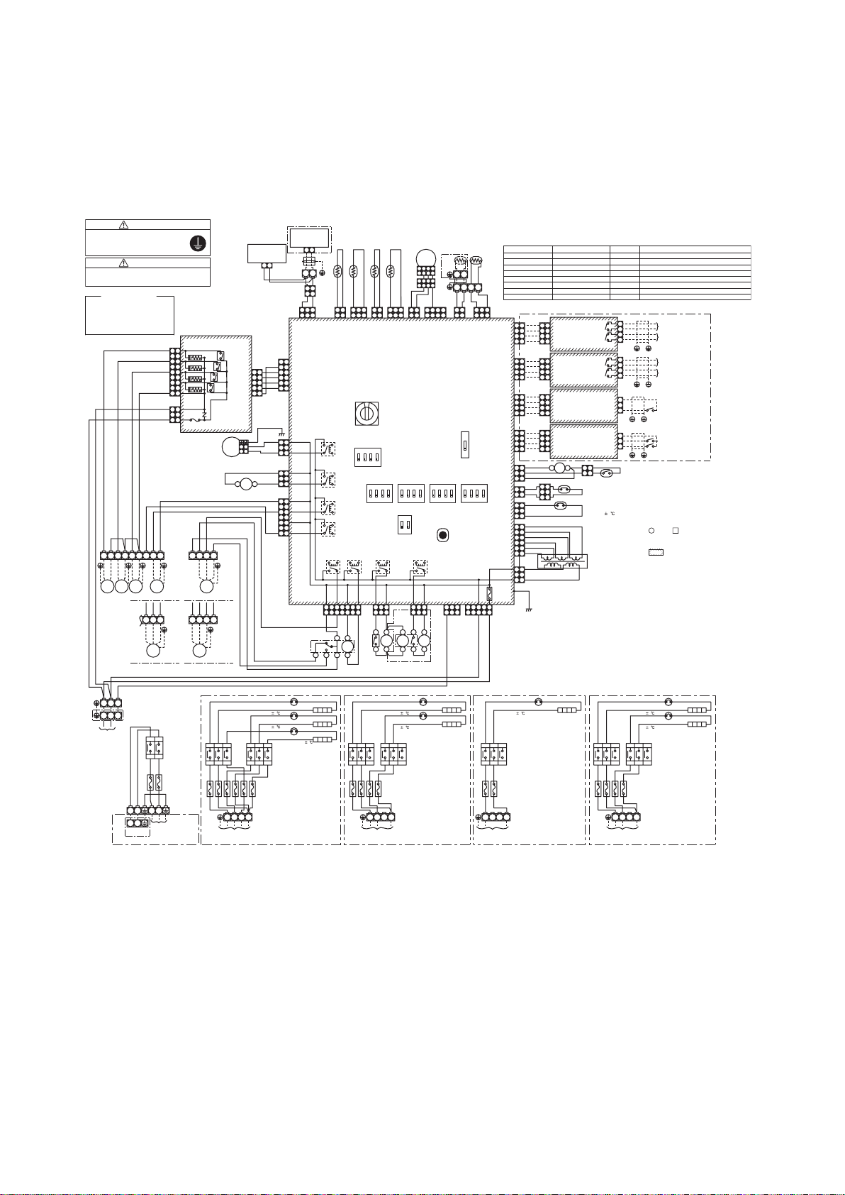
5-3. Outdoor Unit (3 phase type)
HWS-1103H8(R)-E, -1403H8(R)-E, -1603H8(R)-E
P.C. board
MCC-1596
P.C. board
MCC-1597
Hydro
unit
(1103H8R-E
1403H8R-E
1603H8R-E)
only
indicates the teminal block. Alphanumeric characters
in the cycle indicate terminal No.
The two-dot chain line indicates the wiring procured locally.
indicates the P.C. board.
For the hydro unit circuit, refer to the wiring diagram of
the indoor unit.
24
Page 26
5-4. Hot Water Cylinder Unit
Green /
Yellow
AB
TB06(TTW)
To hydro unit
Blue
Double pole thermal cut out
Brown
TTW sensor
Hot water cylinder heater
Blue
Brown
12
TB03(230V)
Supply 220 - 230 V from hydro unit
Cable size 1.5 mm
2
(minimum)
25
Page 27

6 Key Electric Component Rating
6-1. Hydro Unit
HWS-803XWHM3-E, T6-E, D6-E, T9-E
No. Component name
1
Circulating pump
Backup heater 6 kW
2
3
Backup heater 9 kW
Water heat exchange
4
temperature sensor
(TC sensor)
Water inlet temperature sensor
5
(TWI sensor)
Water outlet temperature sensor
6
(TWO sensor)
Heater outlet water temperature
7
sensor
(THO sensor)
Floor inlet temperature sensor
8
(TFI sensor)
Pressure switch
9
10
Low pressure sensor
Bimetal thermostat (auto)
11
Bimetal thermostat (singl e
12
operation)
13
Flow switch
14
Output board (OP)
15
Input board (OP)
16
Remote control (Main)
17
Remote control (Sub)
Water 3-way valve terminal
18
19
Water 2-way valve terminal
Mixing valve terminal
20
21
Circulating pump terminal
22
Booster heater terminal
23
Fuse
Model name
Type name Rating
M3-E T6-E D6-E T9-E
OOOO
OOO –
OOOO –
OOOO –
OOOO –
OOOO –
OOOO –
OOOO –
OOOO –
OOOO –
OOOO –
OOOO –
OP OP OP OP
OP OP OP OP
OOOO
OP OP OP OP
OOOO –
OOOO –
OOOO –
OOOO –
OOOO –
OOOO –
UPS025-65 K 130 AC230 V 0.54 A (MAX)
O–
TCB-PCIN3E AC230 V 0.5 A DC24 V 1 A
TCB-PCM03E Contact input
HWS-AMS11E
HWS-AMS11E
AC 400 V (3N) 6 kW (AC230 V 3 kW
compatible)
AC400V (3N) 9 kW
10 kΩ (25°C)
10 kΩ (25°C)
10 kΩ (25°C)
10 kΩ (25°C)
10 kΩ (25°C)
Operating pressure 4.15 MPa +0 -0.3
MPa
Operating pressure 0. 20 M Pa
Operating temperature 75±3°C DC42 V
/ 0.2 A
Operating temperature 95±5°C
AC250 V / 16 A
Operating flowing quantity 13 /min
AC230 V 0.1 A
2Wire, 3Wire SPST, SPDT type
mountable
AC230 V 0.1 A 2Wire type mountable
AC230 V 0.1 A
3Wire SPST, SPDT type mountable
AC230 V 1.0 A
AC230 V 1.0 A
AC 250 V 30 A
O·········Applied
OP·······Optional accessory
26
Page 28

HWS-1403XWHM3-E, T6-E, D6-E, T9-E
No. Component name
1
Circulating pump
Backup heater 6 kW
2
3
Backup heater 9 kW
Water heat exchange
4
temperature sensor
(TC sensor)
Water inlet temperature sensor
5
(TWI sensor)
Water outlet temperature sensor
6
(TWO sensor)
Heater outlet water temperature
7
sensor
(THO sensor)
Floor inlet temperature sensor
8
(TFI sensor)
Pressure switch
9
10
Low pressure sensor
Thermal protector (auto)
11
Thermal protector (single
12
operation)
13
Flow switch
14
Output board (OP)
15
Input board (OP)
16
Remote control (Main)
17
Remote control (Sub)
Water 3-way valve terminal
18
19
Water 2-way valve terminal
Mixing valve terminal
20
21
Circulating pump terminal
22
Booster heater terminal
23
Fuse
Model name
M3-E T6-E D6-E T9-E
OOOO
OOO –
OOOO –
OOOO –
OOOO –
OOOO –
OOOO –
OOOO –
OOOO –
OOOO –
OOOO –
OOOO –
OP OP OP OP
OP OP OP OP
OOOO
OP OP OP OP
OOOO –
OOOO –
OOOO –
OOOO –
OOOO –
OOOO –
Type name Rating
UPS25-80 130 AC230 V 0.83 A (MAX)
AC 400 V (3N) 6 kW (AC230 V 3kW
compatible)
O–
AC 400 V (3N) 9 kW
10 kΩ (25°C)
10 kΩ (25°C)
10 kΩ (25°C)
10 kΩ (25°C)
10 kΩ (25°C)
Operating pressure 4.15 MPa +0 -0.3
MPa
Operating pressure 0. 20 M Pa
Operating temperature 75±3°C DC42 V
/ 0.2 A
Operating temperature 95±5°C AC250
V 16 A
Operating flowing quantity 17.5 L/min
TCB-PCIN3E AC230 V 0.5 A DC24 V 1 A
TCB-PCM03E Contact input
HWS-AMS11E
HWS-AMS11E
AC230 V 0.1 A
2Wire, 3Wire SPST, SPDT type
mountable
AC230 V 0.1 A 2Wire type mountable
AC230 V 0.1 A
3Wire SPST, SPDT type mountable
AC230 V 1.0 A
AC230 V 1.0 A
AC 250 V 30 A
O·········Applied
OP·······Optional accessory
27
Page 29

6-2. Outdoor Unit
HWS-803H-E
No. Component name Type name Rating
1
Compressor DA220A2F-22L
2
Outdoor fan motor ICF-280-A60-1 Output 60 W
4-way valve coil VHV-01AP552B1 AC220 - 230 full-wave rectifier input, alive time
3
4
Pulse motor valve (PMV) coil CAM-MD12TF-15 DC12 V
5
Compressor case thermostat US-622KXTMQO-SS OFF: 125±4°C ON: 90±5°C
6
Reactor CH-56 5.8 mH, 18.5 A
PC board MCC-1571 Input 1Ø, AC220 - 230 V ± 10 %,
7
10 sec or less
50/60 Hz
28
Page 30

HWS-1103H-E, 1403H-E
No. Component name Type name Rating
1
Compressor DA422A3F-25M
2
Outdoor fan motor (x2) ICF-280-A100-1 Output 100 W
3
Reactor (x2) CH-44 1.4 mH, 25 A
4
4-way valve coil AC220 - 230 V full-wave rectifier input, alive time 10 sec or less
5
Pulse motor valve (PMV) coil UKV-A038 DC12 V
6
Board MCC-1560 Input 3Ø, AC230 V±23 V, 50/60 Hz
7
Compressor case thermostat US-622KXTMQO-SS OFF = 125 ± 4 °C, ON = 90 ± 5 °C
8
PC board MCC-1571 Input 1Ø, AC220 - 230 V ± 10 %, 50/60 Hz
29
Page 31

HWS-1103H8(R)-E, 1403H8(R)-E, 1603H8(R)-E
No. Component name Type name Rating
1
Compressor DA422A3F-27M
2
Outdoor fan motor (x2) ICF-280-A100-1 Output 100 W
3
Reactor CH-78 4.2 mH, 16 A
4
Reactor CH-68 18 mH, 5 A
5
4-way valve coil STF-01A5502E1 AC220 - 230 V
6
Pulse motor valve (PMV) coil UKV-A038 DC12 V
7
PC board (Compressor) MCC-1596
8
PC board (Fan motor drive) MCC-1597
9
PC board (Control) MCC-1599
10
PC board (Noise filter) MCC-1600
11
High pressure switch ACB-4UB83W OFF = 4.15 +0, -0.3 Mpa
12
Compressor case thermostat US-622 OFF = 125 ± 4 °C, ON = 90 ± 5 °C
13
Relay EL200/240 A2-F() Contact = AC480V, 20 A
30
Page 32

6-3. Hot Water Cylinder Unit
Model name
1501
2101
No. Component name
1
Hot water cylinder heater
Hot water cylinder temperature
2
sensor
(TTW sensor)
Thermal cut-out
3
O·········Applied
CSH
M3-E
(-UK)
OOO
OOO
OOO
CSH
M3-E
(-UK)
3001
CSH
M3-E
(-UK)
Type name Rating
– AC230 V 2.75 KW
10 kΩ (25°C)
–
–
Operating temperature
Manual reset 82°C (+3k/-2k)
31
Page 33

6-4. Water Heat Exchange Control Board
HWS-803XWHM3-E, 803XWHT6-E, 803XWHD6-E, 803XWHT9-E
HWS-1403XWHM3-E, 1403XWHT6-E, 1403XWHD6-E, 1403XWHT9-E
Option board
connector
CN208-CN211
Built-in pump
connector
CN603
Relay board connector
CN501
TC sensor connector
Remote control
connector
CN41
CN203
TFI sensor
connector
CN213
TTW sensor connector
CN214
Low pressure sensor connector
CN207, CN212
THO sensor connector
CN206
TWI sensor connector
CN204
TWO sensor connector
CN205
Pressure switch connector
CN201
Overheat protection thermostat
input connector
CN202
Flow switch connector
CN200
Transformer connector
CN102
Hot water cylinder
drive connector
CN601
3WV drive connector
CN602
Mixing valve drive
connector
CN604
Backup heater 1 drive
connector
CN605
Transformer input connector
CN101
AC power supply connector
CN100
Serial input connector
CN305
Backup heater 2 drive connector
CN606
32
Page 34

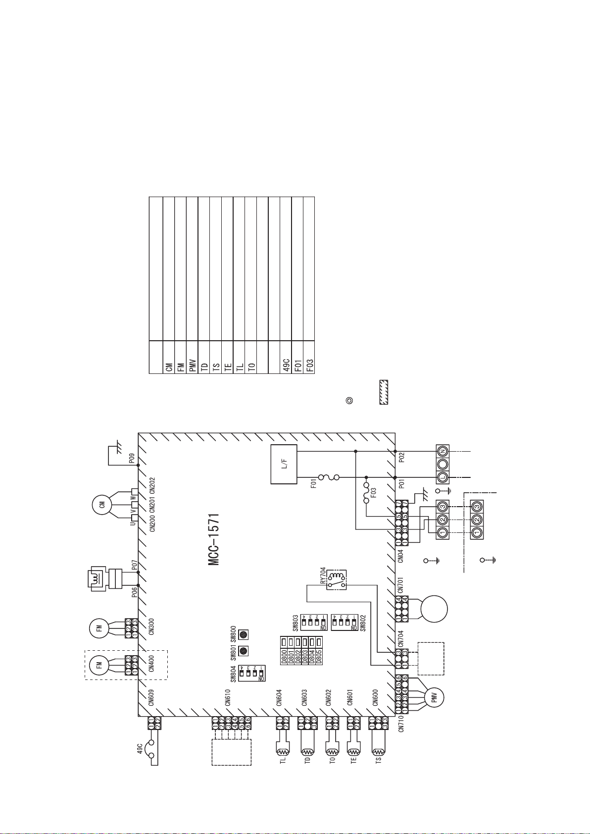
6-5. Outdoor Control Board (Single phase Type)
r
HWS-803H-E
Reactor connection connecto
Power circuit protection
fuse
F100 (250 V, 3.15 A,
plastic case)
Case thermostat connector
CN609(Blue)
4-way valve connector
CN701(White)
Compressor ON
output connector
CN704(
Blue
)
Heater output connector
CN703(Grey)
External input connector
CN610(Yellow)
Special operation switches
SW801
SW804
Fan motor output
CN300 (White)
Compressor output terminals
CN202
CN201
CN200
Electrolytic capacitors
Display change-over switches
SW800
SW803
Temperature sensor connectors
TL CN604(
TD CN603(
TO CN602(
TE CN601(
TS CN600(
Alive, error display LEDs
D800 804(
Initialization switch
Hydro-outdoor communication signal LEDs
White
)
White
)
Yellow
)
White
)
White
)
Yellow
D805(
Green
PMV connector
CN710 (White)
SW802
D503 (Green, Outdoor => Hydro)
D502 (Amber, Hydro => Outdoor)
)
)
4-way valve protection
fuse
F700 (250 V, 3.15 A,
plastic case)
Connecting cable connector
CN04(White)
Connecting cable protection fuse
F03 (250 V, 10 A)
Power circuit protection
fuse
F01 (250V, 25A)
Power supply connection lead
wires
P01(Red)
P02(White)
Earth lead wire
P09 (Black)
33
Page 35

HWS-1103H-E, 1403H-E
Fan motor output (Lower)
CN300(White)
Case thermostat connector
CN609(Blue)
Power circuit protection
fuse
F100(250V,3.15A,
plastic case)
4-way valve connector
CN701(White)
Compressor ON output
connector
CN704(Blue)
Heator output
connector
CN703(Grey)
External input connector
CN610(Yellow)
Special operation switches
SW801
SW804
Display change-over
switches
SW800
SW803
Temperature sensor
connectors
TL CN604(White)
TD CN603(White)
TO CN602(Yellow)
TE CN601(White)
TS CN600(White)
Alive, abnormal display LEDs
D800 804(Yellow)
D805(Green)
PMV connector
CN710(White)
Initialization switch
SW802
Hydro-outdoor communication
signal LEDs
D503 (Green, Outdoor =>Hydro)
D502 (Amber, Hydro => Outdoor)
Fan motor output (Upper)
CN400(White)
4-way valve protection fuse
F700(250V,3.15A
plastic case)
Connecting cable connector
CN04(White)
Connecting cable protection fuse
F03(250V,10A)
Compressor output terminals
CN202
CN201
CN200
Power supply connection
lead wires
P01(Red)
P02(White)
P03(Black)
Power supply protection fuses
F01
(250V,25A)
Electrolytic capacitors
Earth lead wire
P09(Black)
34
Page 36

6-6. Outdoor Unit Control (3 phase type)
HWS-1103H8(R)-E, 1403H8(R)-E, 1603H8(R)-E
MCC-1596 (Compressor IPDU)
CN851
(Red)
Connector for MCC-1597 (CN505)
CN101
(White)
Connector for MCC-1597 (CN502)
CN13
(Black)
Terminal for power relay
CN211
(Red)
Compressor output terminal
, CN212
(White)
, CN213
(Black)
CN19
(Yellow)
, CN20
Terminal for reactor CH78
(Yellow)
F02
Electric circuit protective fuse
(500V, 31.5A)
CN12
(White)
Terminal for MCC-1600 (CN17)
F01
Electric circuit protective fuse
(500V, 31.5A)
CN11
(Red)
Terminal for power relay
CN04
(Red)
Terminal for PTC thermistor
35
Page 37

MCC-1597 (Fan Motor IPDU)
CN750
(White)
Fan motor output (Upper side)
CN700
(Blue)
Fan motor output (Lower side)
CN500
(Red)
Connector for MCC-1600 (CN23)
and reactor CH68
CN504
(Blue)
Connector for MCC-1599
(CN802)
P501
(Black)
Lead wire for grounding
CN602
(Black)
Connector for MCC-1600 (CN51)
CN505
(Red)
Connector for MCC-1596 (CN851)
F500
Electric circuit protective fuse
(250V, 15A)
CN502
(White)
Connector for MCC-1596 (CN101)
36
Page 38

MCC-1599 (Interface (CDB))
CN708
(Blue)
Connector for power relay coil
CN02
Connector for
MCC-1600 (CN10 and CN19)
(Red)
CN608
(White)
Connector for MCC-1600 (CN50)
CN802
Connector for MCC-1597 (CN504)
(White)
CN703
(Gray)
Heater output
connector
CN700
(Yellow)
4-way valve connector
CN690
(Green)
High-pressure
switch connector
CN704
(Blue)
Compressor ON
out put connector
F01
Power supply protective fuse
(250V, 3.15A)
CN609
(Blue)
Case thermostat connector
CN610
Outside input connector
(Yellow)
CN710
(White)
PMV1 Connector
Temp.sensor connector
CN604
Specific operation switch
SW804
SW805
SW806
Display select switch
SW803
Initial setting switch
Power-ON,error display LED
Hydro/Outdoor communication
signal LED
CN01
(White)
Inter-unit cable connector
(White) TL sensor
CN603
(White) TD sensor
CN602
(Yellow) TO sensor
CN601
(White) TE sensor
CN600
(White) TS sensor
SW801
SW800
SW802
D800
to
D804
D805
(Green)
D503
(Green), (Outdoor Hydro)
D502
(Orange), (Hydro Outdoor)
(Yellow)
→
→
37
Page 39

MCC-1600 (Noise Filter)
CN05
(Red)
P
ower supply terminal (L1)
F01
V
aristor protective fuse
(250V, 6.3A)
CN06
(White)
P
ower supply terminal (L2)
F02
aristor protective fuse
V
(250V, 6.3A)
CN07
(Black)
P
ower supply terminal (L3)
F03
aristor protective fuse
V
(250V, 6.3A)
CN20
(White)
P
ower supply terminal (L2)
CN08
(Gray)
N
eutral terminal
CN10
(Red)
T
erminal for MCC-1599 (CN02) and Terminal for PTC thermistor
CN16
(Red)
T
erminal for power relay
CN17
(White)
T
erminal for
MCC-1596 (CN02)
CN18
(Black)
T
erminal for
power relay
CN19
(Gray)
T
erminal for
MCC-1599 (CN02)
CN09
(Brown)
T
erminal for
grounding
CN23
(Red)
C
onnector for
MCC-1597 (CN500)
CN51
(Black)
C
onnector for
MCC-1597 (CN602)
CN50
(White)
C
onnector for
MCC-1599 (CN608)
38
Page 40

7 Refrigeration Cycle / Water System Diagram
7-1. Water System Diagram
M
Fan coil unit
zone1
Boiler
(local)
Booster heater
(local)
By-pass valve
Safety valve
set : 3.5bar
(locally procured)
Motorized 3-way valve
M
AC230V
(locally procured)
Radiator unit
2-way valve for
cooling mode
(locally procured)
AC230V
Strainer
40 mesh
(locally procured)
By-pass valve
(locally procured)
(locally procured)
Drain cock for water charge
Moterized mixing valve
zone2
90°C
10 bar
Relief valve(UK)
AC230V
(locally procured)
AC pump
(locally procured)
1 : 2.75kW
Ø
Cylinder heater
TFI
Floor
heating
Buffer tank(locally procured)
set : 3bar
Pressure relief valve
Air vent valve
set : 1bar
Expansion vessel
THO
AC pump
max : 10bar
(auto)
set : 75 ± 3°C
Thermal protector
set : 95 ± 5°C
Single operation
Thermal protector
Menometer
gage : - 6bar
TWO
Pressure switch
4.15MPa
Water vent
valve
Backup heater
TWI
Flow sw
1 : 3kWØ3 : 6kWØ3 : 9kW
Ø
TC
Low pressure sensor
39
max : 10bar
Water heat exchanger
Water outlet
Pressure relief
Set value : 7bar(UK)
TTW
(manual reset)
82°C (+3k/ -2k)
Thermal cut-out
8~16kW
Outdoor unit
Reducing
(3 place)
(Single phase)
Hot water cylinder
Water inlet
3.5bar
valve(UK)
Local hot water system
Page 41

Installation example of water circuit
(1) (2)
(3) (4)
(5) (6)
The water flowing for a system without buffer tank ((1), (2), (3), (5)) requires17.5 /min (803XWH 13.0 /min) or
more. This water flowing requires 5 or more branches of Floor heating or Radiator etc.
Less than 5 branches may cause a flow deficien cy. In this case, please provide a buffer tank and secondary pumps
as shown in (4).
Please check how to install the boiler (See page 52)
40
Page 42

7-2. Refrigeration Cycle System Diagram
HWS-803XWHM3-E, HWS-803XWHT6-E, HWS-803XWHD6-E, HWS-803XWHT9-E/HWS803H-E
Heating / Hot-water supply
Defrosting / Cooling
Compressor
(DA220A2F-22L)
Accumulator
(1800 cc)
TD
TS
Outdoor unit
4-way valve
(STF-218G)
TO
Outdoor heat
exchanger
Pulse motor valve
(CAM-B30YGTF-2)
TE
Low
pressure
sensor
Pressure switch
Plate-type
water heat
exchanger
TC
Hydro unit
Expansion vessel
TWO
TWI
Manometer
Air vent valve
Backup heater
Safety valve
Circulating pump
(UPS025-65 K 130)
THO
Flow switch
(VH-8706)
Water vent valve
P
Refrigerant R410A ... 1.8 kg
HWS-1403XWHM3-E, HWS-1403XWHT6-E, HWS-1403XWHD6-E, HWS-1403XWHT9-E/
HWS-1103H-E, HWS-1403H-E
Heating / Hot-water supply
Defrosting / Cooling
Compressor
(DA422A3F-25M)
Accumulator
(2500 cc)
TD
TS
Outdoor unit
4-way valve
(STF-0401G)
TO
Outdoor heat
exchanger
Pulse motor valve
(UKV-25D100)
TE
Pressure switch
Plate-type
water heat
exchanger
41
Low
pressure
sensor
TC
Hydro unit
Expansion vessel
TWO
TWI
Manometer
Air vent valve
Backup heater
Safety valve
Circulating pump
(UPS25-80 130)
THO
Flow switch
(VH-8705)
Water vent valve
P
Page 43

HWS-1403XWHM3-E, HWS-1403XWHT6-E, HWS-1403XWHD6-E, HWS-1403XWHT9-E/
HWS-1103H8(R)-E, HWS-1403H8(R)-E, HWS-1603H8(R)-E
Heating / Hot-water supply
Defrosting / Cooling
Muffler
Ø25 x L210
Ø25 x L180
Compressor
(DA422A3F-27M)
Accumulator
(2500 cc)
TD
TS
Outdoor unit
Pressure switch
4-way valve
(STF-0401G)
TO
Outdoor heat
exchanger
Pulse motor valve
(UKV-25D100)
TE
Low
pressure
sensor
Pressure switch
Plate-type
water heat
exchanger
TC
Hydro unit
Expansion vessel
TWO
TWI
Manometer
Air vent valve
Backup heater
Safety valve
Circulating pump
(UPS25-80 130)
THO
Flow switch
(VH-8705)
Water vent valve
P
42
Page 44

8 Operational Description
This chapter describes the working circuit and control of Air to Water Heat Pump about the following operations.
8-1
8-2
8-3
8-4
Item
8-1. Basic Operation
1) Operation control
2) Hot water supply operation
3) Heating operation
4) Cooling operation
8-2. Operation Mode and Control Method
1) Heat pump operation range of hot water supply, heating and cooling
2) Hot water supply operation
3) Heating operation
4) Cooling operation
5) Simultaneous operations of "hot water supply" and "heating"
6) Simultaneous operations of "hot water supply" and "cooling"
7) Boiler control
8) Hot water boost operation
9) Anti bacteria (ANTI BACTERIA) operation
10) Night set back (NIGHT SET BACK) operation
11) FROST PROTECTION operation
12) AUTO operation
13) Night time low-noise operation
8-3. Hydro Unit Control
1) Capacity control (compressor, high-temperature release, low-temperature release)
2) Heater control
3) Circulation pump control
4) Control by the flow switch
5) Mixing Valve control (2-temperature heating control)
6) Room temperature control
7) Room temperature control w ith th e th e r m o s ta t
8) Control of force stop and restart
9) Control of limit of heat pump operation
10)Output signal control 1
11)Output signal control 2
12) Q-H characteristics of hydro unit
13) Automatic restart control
14) Piping freeze prevention control
15) High return water protect control.
8-4. Outdoor unit control
1) PMV (Pulse motor valve) control
2) Discharge temperature release control
3) Current release control
4) Current releases shift control
5) Outdoor fan control
6) Defrosting control
7) Winding heating control
8) Short circuit operation prevention control
9) Over current protection control
10) High pressure release control
11) High pressure switch
12) Compressor case thermostat
13) Bottom plate heater control
Page
44 to 46
47 to 57
58 to 71
72 to 80
43
Page 45

Item Operation flow and applicable data, etc. Operation description
8-1.
Basic
Operation
1) Operation control
Remote controller
Operation
condition selection
Heating: Run/Stop
Hot water supply: Run/Stop
Cooling: Run/Stop
Serial signals transmit
and receive
Hydro
unit
Serial signals
transmit and receive
2WV_W
3WV_W
Hot water supply
heater MG
Mixing Valve
Pressure switch
Lo pressure sensor
Remote control settings
<Heating> Temperature setting
<Hot water supply > Temperature setting
<Cooling> Temperature setting
Auto Temp
Anti Bacteria
Frost protection
Hot waterboost
AC 230 V for Hot water cylinder heater
AC 400 V (3N~) for Back up heater
Thermostat (Cooling/Heating)
Forcible stop input
Water heat
exchange
Sub board
Error Alarm stop output
Defrosting output
Operation output
Boiler "ON/OFF"
Booster Heater
Condensed temperature sensor (TC)
Water inlet temperature sensor (TWI)
Water outlet temperature sensor (TWO)
Water heater outlet temperature sensor (THO)
Water heat
exchange
control board
Hot water cylinder
Floor inlet sensor (TFI)
Overheat prevention thermostat
Flow switch
sensor
(TTW)
1. Purpose
The operations of the
hydro unit and the
outdoor unit are
controlled according to
user-defined operation
condition settings.
2. Details
The operation controls
include those shown on
the left.
3. Operations
1)An operation condition
is selected with the
remote controller.
2)Setting the remote
controller button to
“ON” transmits a signal
to the hydro unit.
3)The hydro unit
controller controls the
operations shown on
the left while also
controlling the water 2way valve, water 3-way
valve, circulation
pump, mixing valve,
hot water cylinder
heater, and backup
heater.
4)The hydro unit
controller transmits an
operation instruction to
the outdoor unit, and
uses serial signals to
transmit and receive
control statuses.
5)The outdoor unit
control unit performs
the operation controls
shown on the left while
also controlling the
compressor, outdoor
fan motor, pulse motor
valve, and 4-way valve.
Hot water cylinder heater
Backup heater 1 power-relay
Serial signals
transmit and receive
Backup heater 2 power-relay
AC pump 1 (Built-in pump)
Outdoor
unit
transmit and receive
Serial
communication
Serial signals
Outdoor
unit control
AC 220 - 230 V for heat pump (Single phase type)
AC 380 - 400V for heat pump (3 phase type)
Outdoor unit contro
Inverter frequency control
Inverter
Waveform synthesis function
Calculation function (Temperature calculation)
AD conversion function
Rapid heating function
Compressor restart
Delay function
G-Tr overcurrent prevention function
Defrosting operation function
Td sensor
Ts sensor
Te sensor
To sensor
PMV
4-way valve
High pressure switch (3 phase type only)
44
Compressor
Outdoor fan motor
Page 46

Item Operation flow and applicable data, etc. Operation description
8-1.
Basic
Operation
2) Hot water supply operation Hot water supply operation
[HOT WATER]
button set to "ON"
Hydro unit
control
Hot water temperature: 40°C to 75°C
Circulation pump "ON/OFF" control
Water 3-way valve control
Hot water cylinder heater control
Operation instruction
signal transmit
Number of compressor revolutions control
Outdoor unit
control
Number of outdoor fan motor revolutions control
Pulse motor valve control
4-way valve control
3) Heating operation Heating operation
ZONE1, 2
button set to "ON"
Heating temperature: 20°C to 55°C
Circulation pump "ON/OFF" control
Hydro unit
control
Water 3-way valve control
Water 2-way valve control
Mixing Valve control
Backup heater control
Operation instruction
Booster heater control
signal transmit
Number of compressor revolutions control
Outdoor unit
control
Number of outdoor fan motor revolutions control
Pulse motor valve control
4-way valve control
Set temperature
(TSC_F)
[°C]
A(40)
B(35)
C(30)
D(25)
E(20)
T1-20
A, B, C, D, E Setting available range 20 to 55°C
T1 Setting available range -15 to 0°C
T3 Setting available range 0 to +15°C
0
T3 20
1. Purpose
Hot water supply
2. Details
This section performs
hot water supply
operation according to
heating conditions
specified for the steps
on the left.
3. Operations
1)Set the [HOT WATER]
remote controller
button to “ON”.
2)The hydro unit
controller starts to
transmit a hot water
supply operation signal
to the outdoor unit
control unit.
3)The hydro unit
performs the operation
controls shown on the
left while also
controlling the
circulation pump, hot
water cylinder heater
“3WV”.
4)The outdoor unit
controls the
compressor, outdoor
fan motor, electric
expansion valve, and
4-way valve based on
the operation signals
transmitted by the
hydro unit.
1. Purpose
Heating
2. Details
This section performs
heating operation
according to heating
conditions specified for
the steps on the left.
3. Operations
1)Set the [ZONE1, 2]
remote controller
button to “ON”.
2)The hydro unit
controller starts to
transmit a heating
operation signal to the
outdoor control unit.
3)The hydro unit
performs the operation
controls shown on the
left while also
controlling the
circulation pump,
backup booster heater
“ON/OFF”, water 2way valve, and water 3way valve.
4)The outdoor unit
controls the
compressor, outdoor
fan motor, electric
expansion valve, and
4-way valve based on
the operation signals
transmitted by the
hydro unit.
45
Page 47

Item Operation flow and applicable data, etc. Operation description
8-1.
Basic
Operation
4) Cooling operation
ZONE1, 2
button set to "ON"
Hydro unit
control
Cooling temperature: 10°C to 25°C
Circulation pump "ON/OFF" control
Water 3-way valve control
Water 2-way valve control
Operation instruction
signal transmit
Number of compressor revolutions control
Outdoor unit
control
Number of outdoor fan motor revolutions control
Pulse motor valve control
4-way valve control
NOTE:
No coding mode in default setting. When use the cooling mode, please change the
FC02 to “0”.
Related FC
FC No. Setting item Default Setting available range
02 Cooling mode availability 1: No 0: Yes
1. Purpose
Cooling
2. Details
This section performs
cooling operation
according to cooling
conditions specified for
the steps on the left.
3. Operations
1)Set the [ZONE1, 2]
remote controller
button to “ON”.
2)The hydro unit
controller starts to
transmit a cooling
operation signal to the
outdoor unit control
unit.
3)The hydro unit
controller performs the
operation controls
shown on the left while
also controlling the
circulation pump, water
2-way valve, and water
3-way valve.
4)The outdoor unit
controls the
compressor, outdoor
fan motor, pulse motor
valve, and 4-way valve
based on the operation
signals transmitted by
the hydro unit.
46
Page 48

Item Operation flow and applicable data, etc.
TO
8-2.
Operation Mode
and Control
Method
1) Heat pump operation range of hot water supply, heating and cooling
The heat pump operation range of hot water supply, heating and cooling is shown on the figures below.
1)HWS-803XWH**-E
TO
43
42
41
40
39
38
37
36
35
34
33
32
31
30
29
28
27
26
25
24
23
22
21
20
19
18
17
16
15
14
13
12
11
10
9
8
7
6
5
4
3
2
1
0
-1
-2
-3
-4
-5
-6
-7
-8
-9
-10
-11
-12
-13
-14
-15
-16
-17
-18
-19
-20
567891011121314151617181920212223242526272829303132333435363738394041424344454647484950
Cooling operation range
Heat pump operation
range of how water
supply and heating
Freeze determination
is executed only once.
Heat pump operation
range of how water
supply and heating.
(Conditional operation range)
Start condition: The compressor
stops for less than 2 hours and
TD>50°C.
Heater for heating
Heater for heating
Heating
thermostat
OFF
Water temperature at inlet (TWI)
2)HWS-1103XWH**-E, 1403XWH**-E, 1603XWH**-E
43
42
41
40
39
38
37
36
35
34
33
32
31
30
29
28
27
26
25
24
23
22
21
20
19
18
17
16
15
14
13
12
11
10
9
8
7
6
5
4
3
2
1
0
-1
-2
-3
-4
-5
-6
-7
-8
-9
-10
-11
-12
-13
-14
-15
-16
-17
-18
-19
-20
5 6 7 8 9 10 11 12 13 14 15 16 17 18 19 20 21 22 23 24 25 26 27 28 29 30 31 32 33 34 35 36 37 38 39 40 41 42 43 44 45 46 47 48 49 50
Cooling operation range
Heat pump operation
range of how water
supply and heating
Freeze determination
is executed only once.
Heat pump operation range of
how water supply and heating
(Conditional operation range)
Start condition: The compressor
stops for less than 2 hours and
TD>40°C.
Heater for heating
Heater for heating
Water temperature at inlet (TWI)
Heating
thermostat
OFF
47
Page 49

Item Operation flow and applicable data, etc.
r
8-2.
Operation Mode
and Control
Method
The following shows the operation modes and controlled objects.
Operation
mode
Cooling
Controlled
object
Heat pump O O O O × × O O × × O
Backup
heater
Hot water
cylinder
heater
Heating
only
only
ЧOЧOЧЧЧЧЧЧЧ
××O×O×O×O×O
Hot
water
supply
only
Heating and Hot water both operate Cooling and Hot water both operate
Hot
side
Heat pump select
for hot water
supply
Heating
side
Heat pump select
for heating
Heating
side
water
supply
2) Hot water supply operation
1)Operation start condition
When the [HOT WATER] remote controller button is pressed
and the following operation start condition is met, the operation
starts.
• TTW < 38°C is detected.
Hot
water
supply
side
Heat pump select
for cooling
Cooling
side
Hot
water
supply
side
Heat pump select
for hot water
supply
Cooling
side
Hot
water
supply
side
O Possible
× Not possible
2)Operation mode determination
An operation mode is determined according to the temperature
of TTW sensor.
TTW senso
• Heat pump operation selection *1 *2
• When TTW < 38°C (a zone in the right figure) is met, the heat
pump operation is selected.
(Hot water cylinder unit)
• Heater operation selection
When 45°C TTW < TSC_H (b zone in the right figure) is
met, the heater operation is selected.
• Thermostat status "OFF" selection
TTW
When TTW TSC_H is met, the thermostat status "OFF" is
selected.
3)Operation stop
The operation stops in the following cases.
• The remote controller gives a stop instruction.
• TTW TSC_H is met.
*1:When the outside temperature is -20°C or below, the heater
operation is selected even if the TTW temperature falls into "a
(Temperature set with
remote controller)
HP_H OFF 45°C
HP_H ON 38°C
TSC_H
Thermostat OFF
Heater operation
b Zone
Heat pump
operation
a Zone
c Zone
zone".
*2:When "Hot water supply" and "Heating" are simultaneously in
operation, the heater operation may be selected depending on
TSC_H is hot water temperature
set with remote controller
the outside air temperature.
Related FC
FC No. Setting item Default Setting available range
1E Upper limit of hot water supply temperature 75°C 60-80°C
1F Lower limit of hot water supply temperature 40°C 40-60°C
20 Heat pump start temperature 38°C 20-45°C
21 Heat pump end temperature 45°C 40-50°C
24 Outside air correction start temperature for hot water supply*
25 Outside air correction temperature for hot water supply*
3
3
0°C -20-10°C
3 degree 0 -15 degree
*3:When the outside temperature is 0°C or below, the boil-up temperature will be higher that setting temperature in hot
water supply mode.
48
Page 50

Item Operation flow and applicable data, etc.
8-2.
Operation Mode
and Control
Method
3) Heating operation
<Operation only for ZONE1>
• This operation is enabled when DP_SW12_2 ZONE1 is set to "OFF" (default).
• The remote controller displays settings, and only the set temperature of can be changed.
<Operation for ZONE1 and ZONE2 (2 temperatures control)>
• This operation is enabled when DP_SW12_2 ZONE1 is set to "OFF" (default) and DP_SW12_3 ZONE2 to "ON".
• The remote controller displays settings, and the set temperatures of
can be changed.
• To set temperatures for and , use SELECT to switch between
and .
• For 2 zone temperatures control, the flow adjustment of MIXING VALVE controls the water temperature of
. For details,
see the description on MIXING VALVE control in 8-3-5.
1)Operation start condition
Pressing the [ZONE1, 2] button of remote controller starts a
heating operation. *1 *2
2) Operation mode selection
An operation mode is determined according to the temperature
of TWI sensor.
• Heat pump operation selection *1 *2
When TWI < TSC_F (d zone in the right figure) is met, the
heat pump operation is selected.
• Thermostat status "OFF"
When TWI TSC_F (e zone in the right figure) is met, the
thermostat status "OFF" is selected.
3)Operation stop condition
When the following condition is met, the heating opera tion
stops.
• The remote controller gives a stop instruction.
TWI
Thermostat off
operation
TSC_F
Heat pump operation
TSC_F is a heating temperature
set with remote controller
e zone
diff2K
d zone
*1:When the outside temperature is -20°C or below, the heater
operation is selected even if the TWI temperature falls into "d
zone".
*2:When "Hot water supply" and "Heating" are simultaneously in
operation, the heater operation may be selected depending on
the outside air temperature.
Related FC
FC No. Setting item Default Setting available range
1A Upper limit of heating (Zone1) limited temperature 55 37-55°C
1B Lower limit of heating (Zone1) limited temperature 20 20-37°C
1C Upper limit of heating (Zone2) limited temperature 55 37-55°C
1D Lower limit of heating (Zone2) limited temperature 20 20-37°C
49
Page 51

Item Operation flow and applicable data, etc.
8-2.
Operation Mode
and Control
Method
4) Cooling operation
Pressing the [ZONE1, 2] button and then [OPERATION MODE] starts a cooling operation.
1) Operation start condition
Pressing the [ZONE1, 2] button and then [OPERATION
MODE] starts a cooling operation.
2) Op
eration mode selection
An operation mode is determined according to the
temperature of TWI sensor.
• Heat pump operation selection *1
When TWI TSC_F (d zone in the right figure) is met, the
heat pump operation is selected.
• Thermostat status "OFF"
When TWI < TSC_F (e zone in the right figure) is met, the
thermostat status "OFF" is selected.
3)Operation stop condition
When either of the following conditions is met, th e cooli ng
operation stops.
• The remote controller gives a stop instruction.
• The operation is switched to heating.
*1:When the outside temperature is 10°C or below, cooling does
not start even if the TWI temperature falls into "d zone".
Related FC
FC No. Setting item Default Setting available range
02 Cooling mode availability 1: Not permit 0: Permitted
18 Upper limit of cooling setting temperature 25 20-30°C
19 Lower limit of cooling setting temperature 10 10-20°C
TSC_F
(Temperature set with
remote controller)
TSC_F
TWI
Heat pump operation
d zone
TSC is a cooling temperature
set with the remote controller
(cooling)
e zone
Thermostat off operation
Diff : 2k
5) Simultaneous operations of "hot water supply" and "heating"
At the time of "Hot water supply" and "Heating" simultaneous
operation, the operation mode is select as follows depending on
the outside air temperature.
• f zone Operation with hot water supply priority
A heat pump operation is performed in the hot water supply
side, and a heating operation in the heating side.
• g zone Operation with heating priority
A heat pump operation is performed in the heating side, and
a cylinder heater operation in the hot water supply side.
0
(FC22)
-20
TO
Hot water
supply heat
pump priority
operation
Heating heat
pump priority
operation
Heater operation
f zone
Diff : 5deg
g zone
Diff : 5deg
h zone *3
Operation mode by zone
Zone Hot water supply side Heating side
f Heat pump *2 Stop *2
g Heater Heat pump
h Heater *3 Heater *3
*2:Note that after a heat pump operation for "Hot water supply" is selected in f zone, when the operation moves to a
heater operation for "hot water" and then 5 minutes has passed (Hot water supply operation in b zone), the operation
mode changes as follows.
Zone Hot water supply side Heating side
f' Heater Heat pump
When TTW 45°C (FC: changeable) is met, the operation ends f' zone and returns to f zone.
*3:If the h-zone operation starts while external temperature is higher than -20°C, the h-zone operation continues for 60
minutes.
50
Page 52

Item Operation flow and applicable data, etc.
Related FC
FC No. Setting item Default Setting available range
Maximum HP operation time for hot water heater, when “hot
07
water supply” + “heating mode” both operate.
22 Priority mode switch temperature 0°C -20-20°C
* Note: When user selects “hot water supply” and “ZONE1,2”, and Heat pump selects hot water supply mode, the
Maximum operating time of heat pump is 30 min.
8-2.
Operation Mode
and Control
Method
6) Simultaneous operations of "hot water supply" and "cooling"
For simultaneous operations of "hot water supply" and "cooling", basically cooling runs by a heat pump operation, and
hot water supply by a heater operation.
Hot water supply side Cooling side
Normal Heater * Heat pump *
* By setting FC_01 to “1”, heat pump ope ration for “hot water supply” is permitted. Under the setting, the heat pump
runs for the hot water supply side when TTW is less than 38°C.
Hot water supply side Cooling side
TTW<38°C Heat pump stop
The operation mode returns to normal when TTW become 45°C or more (FC: variable).
Related FC
FC No. Setting item Default Setting available range
02 Cooling mode availability 1: Not permit 0: Permitted
0F Heat pump operation for hot water supply permitted/not
permitted
30 min 0-120min
0: Not permit 1:Permitted (Heat pump
may run for hot water
supply.)
51
Page 53

Item Operation flow and applicable data, etc.
8-2.
Operation Mode
and Control
Method
7) Boiler control
The boiler assists the hot water supply operation and heating operation according to the boiler’s position.
7-1)Boiler setting
• TCB-PCIN3E optional P.C. board is required. Connect its connection cable to CN208 port on the PC board of the
hydro unit.
• Setting DPSW on the hydro unit: DP_SW13_2=”ON/OFF” switches “Using boiler/Not using boiler (Default)”.
Set the switch to “ON” when using the boiler.
• The temperature switching the boiler and heat pump: FC_23=-10°C (Default) See the next item.
The boiler output becomes effective when the outside air temperature is -10°C or less.
• Boiler position setting: DP_SW02_1=”ON/OFF” must be switched in accordance with the boiler position from the
3-way valve; before the 3-way valve/after the 3-way valve and in the heating side (Default).
When the switch is set to “ON”, the boiler runs in the hot water supply operations or heating operation. The action
of the 3-way valve depends on heat pump’s action and the boiler follows their action.
When the switch is set to “OFF”, the boiler runs in heating operation. Also, the boiler runs when the heat pump is
running for hot water supply while heating and supplying hot water simultaneously.
• Priority setting between the boiler and hydro unit: FC_3E=”0/1” switches the running priority; hydro unit (Default)/
boiler.
When FC_3E is set to “0” (Default), the hydro unit has priority, the boiler stops as temperature reaches the hydro
unit’s temperature setting.
When FC_3E is set to “1”, the boiler continues to run even after temperature reaches the hydro unit’s temperature
setting. (The setting of FC_3E is effective during the HP+Boiler operation.)
• Coordination setting of the boiler and heat pump: when FC_5B=”0”, the boiler and heat pump runs simultaneously
(Default).
when FC_5B=”1”, only the boiler runs (however, if the external air temperature becomes the boiler-HP switching
temperature or more within 60 minutes, the heater may run instead for up to 60 minutes.)
when FC_5B=”2”, the heater runs.
*1:When FC_3E is set to “0” (Default), the hydro unit has priority, the boiler stops as temperature reaches the hydro
unit’s temperature setting.
When FC_3E is set to “1”, the boiler continues to run even after temperature reaches the hydro unit’s
temperature setting.
<Installation example>
DP_SW02_1=“OFF”(The boiler is placed after the 3-way valve and in the heating side.)
Option
Boiler
Hydro
Outdoor
unit
* Boiler & HP switching temp setting FC23= -10
** Boiler control/functionality setting FC5B= 0 (HP+Boiler)
*** Hot water & cooling priority setting (FC_0F=“1” hot water
priority is necessary.)
Buffer
Radiator
HEATING Boiler + HP*** HP
HOT WATER HP HP
HEATING & HOT
WATER
COOLING – HP (TO 10)
COOLING & HOT
WATER
TO<=-10* -10*<TO
Boiler for heating
HP for hot water
or heating
HP for cooling
Heater for hot
water***
DP_SW02_1=“ON”(The boiler is placed before the 3-way valve.)
Outdoor
Hydro unit
Unit
* Boiler & HP switching temp setting FC23= -10
** Boiler control/functionality setting FC5B= 0 (HP+Boiler)
*** Hot water & cooling priority setting (FC_0F=“1” hot water
priority is necessary)
Buffer tank
Radiator
HEATING Boiler + HP** HP
HOT WATER Boiler + HP** HP
HEATING & HOT
WATER
COOLING – HP (TO 10)
COOLING & HOT
WATER
TO<=-10* -10*<TO
Boiler + HP** HP
HP for cooling
Heater for hot
water***
HP
HP for cooling
Heater for hot water***
HP for cooling
Heater for hot water***
52
Page 54

Item Operation flow and applicable data, etc.
K
8-2.
Operation Mode
and Control
Method
7-2)Boiler-output control
• I zone: heat pump operation
Normally the heat pump operation is executed in the zone.
• J zone: heat pump operation and boiler operation *1
In the zone, the heat pump + boiler operation (*2) is executed and the heater operation is executed in the hot-watersupply side.
TO
Heat pump
I zone
Diff : 5
operation
E
-10
Heat pump &
J zone
boiler operation
*2:Operation mode is not changed with the outside temperature when an external signal to control the limit of heat
pump limit operation (see 3-9) is input.
7-3)Boiler output limit control
The boiler power output is limited depending on the settings of boiler position (DPSW02_1) and FC62.
Boiler position
(DPSW02_1)
(After 3-way valve, heating side)
(Before 3-way valve)
0
0
(Activate/deactivate A02 error
FC62
detection)
0 TWI or TWO or THO<58°C
1 TWI or TWO or THO<58°C
0 TWI or TWO or THO<70°C
1No limit *1
Temperature range in which the boiler signal is output
(Detected temperature of TWI, TWO or THO)
7-4)A02 error detection while the boiler is running
A02 error detection is deactivated depending on the settings of FC62 and whether the boiler is installed or not
(DPSW13_2).
Boiler is installed or not
(DPSW13_2)
0
(Not installed)
1
(Installed)
(Activate/deactivate A02
FC62
error detection)
0 TWI or TWO or THO 70°C (Beep)
1 TWI or TWO or THO 70°C (Beep)
0 TWI or TWO or THO 70°C (Beep)
1 No error detection *1 (No beep)
Temperature recognized as A02 error
(Detected temperature of TWI, TWO or
THO)
*1 If a user runs the boiler under the condition that no limit has been set, and hot water from the boiler has damaged parts
inside of the hydro unit, the user is fully responsible for the damage.
Related FC
FC No. Setting item Default Variable range
23 Boiler-heat pump switching temperature -10°C -20-20°C
3E Control priority between the hydro unit and boiler
(Control valid for operating heat pump mode)
5B Coordination of the boiler and heat pump 0: Boiler and Heat pump 1: Boiler only
62 Activate/deactivate A02 error detection 0: Activate 1: Deactivate
0: Hydro unit control Independent temperature
control for the hydro unit
and boiler
2: Heater only
53
Page 55

Item Operation flow and applicable data, etc.
8-2.
Operation Mode
and Control
Method
8) Hot water boost operation
A hot water boost operation heats the water quickly to the set temperature TSC_H = 75°C (FC_09).
1) How to operate
• When pressing the [HOT WATER BOOST] button after pressing the remote controller [HOT WATER] button, a heat
pump operation in progress in the heating side switches to in the hot water side, and continues the operation
regardless of the hot water supply start condition, TTW < 38°C. In addition, the hot water cylinder is immediately
energized to start a Hot water supply operation under TSC_H = 75°C.
• A hot water boost operation returns to the usual operation after 60 minutes passed or reached 75°C.
• The remote controller display during a hot water boost operation is the same as the set temperature display of a usual
Hot water supply operation.
• The usual set temperature change is used for changing the set temperature during a hot water boost operation.
Change the BOOST set temperature with FC_09, if necessary.
HOT WATER button set to "ON"
HOT WATER BOOST button set to "ON"
Current heat pump
Heating side
operation
Hot water
supply side
Switches to Hot water
supply operation
75°C hot water operation (FC_09)
60 minutes operating time (FC_08)
Usual operation
Related FC
FC No. Setting item Default Setting available range
09 HOT WATER BOOST set temperature 75°C 40-80°C
08 HOT WATER BOOST operation time 60 min 30-180 min
Every 10 min
54
Page 56

Item Operation flow and applicable data, etc.
8-2.
Operation Mode
and Control
Method
9) Anti bacteria (ANTI BACTERIA) operation
An anti bacteria operation regularly performs a Hot water supply operation with the set temperature TSC_H = 75°C (can
be set with FC_0A).
1) How to operate
• Pressing the [HOT WATER] button and then the remote controller [ANTI BACTERIA] button changes the setting to
TSC_H = 75°C at the set cycle and time (both can be set with the remote controller FC) to start ANTI BACTERIA
operation.
• The first anti bacteria operation starts when press the [ANTI BACTERIA] button and starting time come.
• When the set temperature 75°C is reached after the ANTI BACTERIA operation started, the set temperature remains
another 30 minutes (can be set with FC_0B).
• The priority zone determined by the outside temperature selects an operation, Hot water heat pump or hot water
supply heater.
• The hot water heat pump operation, when selected, ignores the hot water supply start condition (TTW < 38°C) and
forcibly performs a hot water operation.
• During ANTI BACTERIA operation (Forcible hot water operation at 75°C), the hot water set temperature display is
not changed. If it is changed from the remote controller, the normal hot water set temperature will be changed.
HOT WATER button set to "ON"
ANTI BACTERIA button set to "ON"
Anti bacteria start time
75°C hot water supply operation
75°C hot water supply operation for 30 minutes
Usual hot water supply operation
(Set temperature: 40°C to 75°C)
Caution
• During a 75°C hot water supply operation with ANTI
BACTERIA, the remote controller does not display 75°C.
• Be careful not to burn yourself; Output water may be hotter
than that displayed on the remote controller.
Related FC
FC No. Setting item Default Setting available range
0A Anti bacteria set temperature 75°C 65-80°C
0B Anti bacteria holding time 30 min 0 - 60 min
Remote control OCAnti bacteria start time 22:00 0:00-22:00
Remote control ODAnti bacteria operation cycle 7 days Every day to 10 days
55
Page 57

Item Operation flow and applicable data, etc.
8-2.
Operation Mode
and Control
Method
10)Night set back (NIGHT SET BACK) operation
A night set back operation performs heating at 5K lower and cooling at 5K higher temperatures against the remote
controller set temperature from the setting start time (22:00) to the end time (6:00) every day.
Note) • Set the remote controller time before starting a NIGHT SET BACK operation.
• The set time can be changed with remote controller FC. (See page 114)
Related FC
FC No. Setting item Default Setting available range
Remote controllerOENight set back start Time setting 22:00 0:00-23:00
Remote controllerOFNight set back end Time setting 6:00 0:00-23:00
26 Night set back setting Temperature width 5 degree 3 -20 degree
58 Night set back setting activate 0. Zone 1 & 2 1. Zone 1 only
11)FROST PROTECTION operation
A frost protection operation performs heating at the set temperature RSC_F = 15°C (FC).
1)How to operate
• Pressing the remote controller [ZONE1, 2] button and then the [FROST PROTECTION] button starts a heating
operation at the set temperature of 15°C.
• Pressing again the [FROST PROTECTION] button cancels the FROST PROTECTION operation.
• The remote controller displays "F" as the temperature during FROST PROTECTION.
• A set temperature change during a FROST PROTECTION operation cancels the operation.
2)Automatic stop of frost protection operation
• The operation period of frost protection can be set at FC 12 and 13 on the remote control.
Longest period available: 20 days and 23 hours
• By entering the operation period (day and hour) at FC 12 and 13 on the remote control and pressing the [Frost
Protection] button, the operation period is set and the frost protection operation will automatically be finished after
the period has passed.
• The operation period setting (day and hour) is stored in the memory.
Related FC
FC No. Setting item Default Setting available range
3A FROST PROTECTION Yes / No 1: Yes 0: No
3B FROST PROTECTION Set temperature 15°C 10-20°C
12 (remote control) FROST running period (days) 0 0-20 days
13 (remote control) FROST running period (hours) 0 0-23hours
56
Page 58

Item Operation flow and applicable data, etc.
8-2.
Operation Mode
and Control
Method
12)AUTO operation
An auto operation sets the water temperature TSC_F depending on the outside air temperature TO by following the table below.
1) How to operate
• Pressing the remote controller [ZONE1, 2] button and then the [AUTO] button starts AUTO operation for heating. An
operation starts at the set temperature of straight -line approximation for the following: water temperature 40°C with
the outside temperature -20°C (FC), 35°C with -10 °C (T1)(FC), 30°C with 0°C (FC), 25°C with 10°C (T3), and 20°C
with 20°C (TC).
• For 2-temperature control, although Auto-Curve in ZONE2 shows 80% of that of ZONE1 (FC), the water temperature
setting does not fall below 20°C.
• During an AUTO operation, pressing again the [AUTO] button returns to the usual manual set heating operation.
• The remote controller displays "A" as the temperature during an AUTO operation.
(When 2-temperature control is enabled, the remote controller displays "A".)
• Long-pressing the [AUTO] button during an AUTO operation activates the Auto-Curve FC change mode, enabling
the set Auto-Curve water temperature to be shifted by ±5K range (FC_27). When using the auto curve shift function
please note the maximum and minimum water temperature at 55°C and 20°C respectively.
• Even if the temperature setting is changed during an AUTO operation, the operation continues.
• An AUTO operation works with a heating operation only, not with a cooling or a hot water supply operation.
Auto-Curve
ZONE1
40(A)
35(B)
30(C)
25(D)
20(E)
Auto-Curve
ZONE2
-20
-10
(T1)
010
(T3)
20
Related FC
FC No. Setting item Default Setting available range
18 Upper limit of cooling set temperature 25°C 20-30°C
19 Lower limit of cooling set temperature 10°C 10-20°C
1A Upper limit of heating (ZONE1) set temperature 55°C 37-55°C
1B Lower limit of heating (ZONE1) set temperature 20°C 20-37°C
1C Upper limit of heating (ZONE2) set temperature 55°C 37-55°C
1D Lower limit of heating (ZONE2) set temperature 20°C 20-37°C
27 Set temperature shift with heating set to Auto 0 -5 to 5 k
29 Outside air temperature T1 temperature -10°C -15-0°C
2B Outside air temperature T3 temperature 10°C 0-15°C
2C Set temperature when out side air temperature is -20 °C. 40°C 20-55°C
2D Set temperature when out side air temperature is -10 °C (T1). 35°C 20-55°C
2E Set temperature when out side air temperature is 0 °C. 30°C 20-55°C
2F Set temperature when out side air t emperature is 10 °C (T3). 25°C 20-55°C
30 Set temperature when out side air temperature is 20 °C. 20°C 20-55°C
31 Auto-Curve ratio of ZONE2 80% 0-100%
13)Night time low-noise operation
A night time low-noise operation reduces operation frequency and the number of outdoor fan rotations for a certain period
during night time as noise control for urban operation.
Maximum operation frequency 40.2 Hz (Hot water supply/ Heating/ Cooling)
Maximum fan tap 460 rpm (803H-E)
500 rpm (1103H-E, 1403H-E)
(1103H8(R)-E, 1403H8(R)-E, 1603H8(R)-E)
The night time low-noise operation is enabled/ disabled by changing the remote controller FC_09.
<How to set> - Refer to “11. Night time Low-noise Setting” on page 139.
1) Press the TEMP. and TEST button at the same time for 4 seconds or longer. (Shifted to the night time lownoise setting mode)
The Code No. field displays "09", and the DATA "0000", , and being displayed blink.
2) Press TIME to set enable "1" or disable "0".
Pressing SET change DATA and display to be lit and the setting is confirmed.
(When "1" as enable is set, the night time low-noise setting is enabled, the control starts at the set start time.)
3) Press TEST to exit the night time low-noise time setting mode. The and goes out, returning to its
original status.
57
Page 59

Item Operation flow and applicable data, etc.
8-3.
Hydro Unit Control
1) Capacity control (compressor, high-temperature release, low-temperature release)
This unit controls the compressor frequency and heater output so that the water outlet temperature matches the remote
controller set temperature.
1-1)Compre ssor control
• Calculates the different between the remote controller set temperature (TSC_H, TSC_F) and the water outlet
temperature (Hot water supply: THO, Heating: TWO).
• Sets the Hz signal correction amount that determines the number of compressor rotations by the temperature
difference.
• Detects the number of compressor rotations.
• Compares the Hz signal correction amount and the current operation Hz, and changes the compressor output
according to the difference.
* The control details are the same for hot water supply, heating, and cooling.
Remote controller
Temperature settings
(TSC_H, TSC_F)
TSC_H-THO for hot water supply
TSC_F-TWO
for heating/cooling
Hz signal correction
Number of compressor
rotation detection
Hz signal correction Operation Hz
Inverter output change
Number of compressor
rotation change
Hydro unit
Water outlet temperature
(THO, TWO)
Compressor frequency changeable range 10 Hz to 70 Hz (803, 1403H-E, 1603H8(R)-E)
10 Hz to 60 Hz (1103H-E, 1103H8(R)-E)
10 Hz to 66 Hz (1403H8(R)-E)
58
Page 60

Item Operation flow and applicable data, etc.
8-3.
Hydro Unit Control
1-2)High temperature release control
A heat pump operation is performed as shown in the table below according to the TC sensor detecting temperature.
• For the detected temperature, TC (= TWO + 2 degree) of a heat pump operation is used. The values of T7 through
T10 varies depending on TWI. (See the table below)
• If the compressor frequency instruction from the hydro unit is less then 10 Hz, the compressor stops.
• TC > 62°C causes the compressor to stop abnormally. When the compressor restarts 140 seconds after the stop
and TC > 62°C is not detected for 20 minutes, the abnormal stop counter is cleared. 10 times of compressor
abnormal stop stops the operation of heat pump, and fault code A11 is displayed on the remote controller.
* If the heat pump operation is switched to other operation, the abnormality detection counter is reset to 0.
TC (TWO+2)
T11
(62.0°C)
T10
T9
T8
R1
(slow up)
T7
Forcible stop
O (down)
P (slow down)
Q (keep)
R2 (slow up)
S (normal)
Zone Control operation
R1 Increase compressor frequency by 1.2 Hz every
60 sec.
R2 Increase compressor frequency by 0.6 Hz every
60 sec.
O Decrease compressor frequency to 70% every
10 sec.
P Decrease compressor frequency by 3 Hz every
10 sec.
Q Keep compressor frequency.
TC=TWO+2degree (°C)
TWI T7T8T9T10T11
TWI<30 57.0 59.0 60.0 61.0 62.0
30 TWI<35 57.0 59.0 60.0 61.0 62.0
35 TWI<40 56.5 58.5 59.5 60.5 62.0
40 TWI<45 56.5 58.5 59.5 60.5 62.0
45 TWI<50 56.0 58.0 59.0 60.0 62.0
50 TWI 56.0 58.0 59.0 60.0 62.0
1-3)Low temperature release control
A heat pump operation is performed as shown in the table below according to the TC sensor detecting temperature.
• For the detected temperature, TC = TWO of a heat pump operation is used. The values of T7 through T10 varies
depending on TWI. (See the table below)
• If the compressor frequency instruction from the hydro unit is less then 10 Hz, the compressor stops.
• TC < 3°C causes the compressor to stop abnormally. When the compressor restarts when 140 seconds has
passed after the stop and TC < 3°C is not detected for 20 minutes, the abnormal stop counter is cleared. 10 times
of compressor abnormal stop stops the operation of heat pump, and fault code A11 is displayed on the remote
controller.
* If the heat pump operation is switched to other operation, the abnormality detection counter is reset to 0.
TC (TWO)
S (normal)
T7
T8
T9
T10
R1
(slow up)
R2 (slow up)
Q (keep)
P (slow down)
O (down)
T11
Forcible stop
TC=TWO (°C)
TWI T7T8T9T10T11
TWI<10 10.0 8.0 6.0 4.0 3.0
10 TWI<15 10.5 8.5 6.5 4.5 3.0
15 TWI<20 11.0 9.0 7.0 5.0 3.0
20 TWI 11.5 9.5 7.5 5.5 3.0
59
Zone Control operation
R1 Increase compressor frequency by 1.2 Hz every
60 sec.
R2 Increase compressor frequency by 0.6 Hz every
60 sec.
O Decrease compressor frequency to 70% every
10 sec.
P Decrease compressor frequency by 3 Hz every
10 sec.
Q Keep compressor frequency.
Page 61

Item Operation flow and applicable data, etc.
)
8-3.
Hydro Unit Control
2) Heater control
2-1) Hot water supply operation
During a hot water heat pump operation, the unit energizes the hot water cylinder heater (2.75 kW) when all the
following conditions are met. Note that when the hot water supply set temperature (TSC_F) is reached, the unit stops
energizing the heater.
• When 30 minutes has passed after the hot water heat pump operation started.
• The water inlet temperature (TWI) reaches 50°C.
• The hot water cylinder sensor reaches the HP_OFF temperature (45°C-FC).
• The HP_ON temperature (38°C-FC) is reached without the hot water HP status.
• HOT WATER BOOST operation is in progress.
TTW
Z zone
85
Y zone
Heater off
TSC_H
Heat pump_OFF(45)
2-2)Heating operation
1)Heater control at the time of heat pump operation
• Object to be controlled: Backup heater
The backup heater control starts when 13 minutes has passed after the heating heat pump operation started and
select the ZONE (A-D). The backup heater control increases, decreases, or maintains the number of heaters
every 10 minutes (FC) depending on the difference between the heating set temperature (TSC_F) and the heater
outlet temperature (THO). When the heating set temperature (TSC_F) is reached, the hydro stops energizing
the backup heater.
THO
E zone
70
D zone
TSC_F-0
(+2)
C zone
*1
TSC_F-2
B zone
TSC_F-4
A zone
X zone
Heater on
(Heater on without
hot water heat
pump)
Abnormality detection (A02 displayed)
Abnormality detection (A03 displayed
Hot Water Boost
Heater on only with
Hot Water Boost in operation
Heat pump_ON (38°C)
(Hot water heat pump)
Diff : 2K
Heater off
Heater output down every
5, 10, 15, or 20 minutes
Diff : 2K
KEEP
Diff : 2K
Heater output up every
10, 20, 30, or 40 minutes
Diff : 2K
TSC_H-4
*1 HWS-803H-E only
Status Heater ON / OFF
Heater 1 Backup heater 3 kW = ON
Heater 2 Backup heater 9 kW = ON
The single-phase model of 3 kW has the backup heater 1 only.
The three-phase model of 6 kW has heater 1+2 of 6 kW.
60
Page 62

Item Operation flow and applicable data, etc.
8-3.
Hydro Unit Control
2)Control at the time of heating heater operation
• Controlled Object: Backup heater, Booster heater
The backup heater control starts when 13 minutes has passed after the heating heat pump operation started.
The backup heater control increases, decreases, or maintains the number of heaters every 10 minutes (FC)
depending on the difference between the heating set temperature (TSC_F) and the heater outlet temperature
(THO). Note that when the heating set temperature (TSC_F) is reached, the unit stops energizing the heater.
THO
E zone
70
D zone
TSC_F+2
C zone
Abnormality detection
Diff : 2K
Heater off
Heater output down every
5, 10, 15, or 20 minutes
TSC_F-0
B zone
TSC_F-2
A zone
Diff : 2K
KEEP
Diff : 2K
Heater output up every
10, 20, 30, or 40 minutes
Status Heater ON / OFF
Heater 1 Backup heater 3 kW = ON
Heater 2 Backup heater 9 kW = ON
Heater 3 Heater 2 + Booster heater
The single-phase model of 3 kW has the backup heater 1 only.
The three-phase model of 6 kW has heater 1+2 of 6 kW.
Booster heater operation come only output signal. (Booster heater activate under heater only mode)
Related FC
FC No. Setting item Default Setting available range
20 Hot water supply heat pump start temperature 38°C 20-45°C
21 Hot water supply heat pump stop temperature 45°C 40-50°C
33 Heater control of down time 1:10 min 0:5 min 2:15 mi n 3:20 min
34 Heater control of up time 0:10 min 1:20 min 2:30 min 3: 40 min
2-3)Heater control at the time of defrosting
• Object to be controlled: Backup heater
When a defrosting operation starts during the heating heat
pump operation, the unit energizes a backup heater (3 kW)
according to the heater outlet temperature sensor (THO) and
the set temperature (TSC_F) as follows.
TSC_F-β (β=2)
TSC_F-α (α=4)
THO
TSC_F
Heater off
Heater 1
Heater 1
1)When the heater outlet temperature sensor (THO) drops to
the temperature of 2°C below the set temperature
Defrosting ends according to the usual heater control.
Status Heater ON / OFF
Heater 1 Backup heater 3 kW = ON
2-4)Forcible heater energization
To prevent freeze, the unit energizes or stops energizing a backup heater (3 kW) regardless of the unit status, not
operated or in operation.
• Object to be controlled: Backup heater
1)Energization start condition: TWO < 4 or TWI < 4 or THO < 4
2)Energization stop condition: TWO 5 and TWI 5 and THO 5
Defrosting ends according to the usual heater control.
2-5)No heater operation
According to the DP_SW11 setting, the unit switches the energize/ not energize for the hot water cylinder, backup
heater, and booster. For details, see 10-1.
(Caution)
All heater should be added to this Air to water system.
The system has been designed to operate with all electrical heaters energized.
61
Page 63

Item Operation flow and applicable data, etc.
8-3.
Hydro Unit Control
3) Circulation pump control
One circulation pump (enhancing pump P2) can be connected to the unit in addition to t he built-in circ ulation
pump P1.
You can change the settings of the built-in pump P1 and the enhan cing pump P2 usin g DP_SW10-1, 2, and
3 in the hydro unit.
Item Operation Initial value DPSW
AC pump 01: Built-in pump P1’s action during how water supply operation:
HP operation only/Always energized
02: Built-in pump P1’s action during heating operation:
Always energized/Turned off when TO sensor detect over than 20°C.
03: Enhancing pump P2’s action:
Interlock/Non-interlock with the built-in pump P1
04: None
If the enhancing pump P2 is set to Non-interlock, the pump P1 is always energized.
3-1)Controlling the built-in circulation pump P1
Pump type: AC motor, rated voltage 230V, three-speed (changed manually)
The pump operation starts under the condition below:
• When the [HOT WATER] or [ZONE1,2] button is pressed.
The pump operation stops under the condition below:
• When the [HOT WATER] or [ZONE1,2] button is pressed. (Operation will stop fully in about 1 minute.)
The pump operation stops/restarts under the conditions shown below.
• When changing operation modes, the pump stops for 30 seconds.
Boiler is installed or not
(DPSW13_2)
0
(Not installed)
1
(Installed)
Boiler position
(DPSW02_1)
0 (After 3-way valve, heating side) 70°C / 68°C
1 (Before 3-way valve) 70°C / 68°C
0 (After 3-way valve, heating side) 70°C / 68°C
1 (Before 3-way valve) 58°C / 55°C
Stop/restart temperatures
(TWI or TWO or THO)
OFF: HP operation
only
OFF: Always
energized
OFF: Interlock
P1 pump control
SW10-1
SW10-2
*2
SW10-3
3-2)Controlling the built-in pump P1 during the hot water supply operation
You can change the action of the built-in pump P1 during the hot water supply operation using DP_SW10-1.
• DP_SW10-1 OFF(Default): The pump stops as the HP for hot water supply stops.
• DP_SW10-1 ON: The pump is always energized.
3-3)Controlling the built-in pump P1 during the heating operation
You can change the action of the built-in pump P1 during the heating operation using DP_SW10-2.
• DP_SW10-2 OFF(Default): The pump is always energized.
• DP_SW10-1 ON : The pump stops when To ≥ 20°C. (Practically the HP for heating is turned off.)
3-4)Enhancing circulation pump P2
Pump type: AC motor, rated voltage 230V, connectable directly up to 200W rated power output.
You can select whether the pump P2 is interlocked with the pump P1 using DP_SW10-3. The pump P1 is always
energized if the pump P2 is not interlocked.
3-5)Controlling the enhancing pump P2
You can change the action of the enhancing pump P2 during cooling operation by setting FC64.
• FC64=”00”(Default): The pump is always energized.
• FC64=”01” : The pump is always stopped.
3-6)Controlling the built-in pump P1 during cooling operation controlled with the room temperature thermostat or room
temperature remote control.
You can change the action of the built-in pump P1 by setting FC65.
• FC65=”00”(Default): The pump is always energized.
• FC65=”01” : The pump is stopped when the thermostat is turned off.
Related FC
FC No. Setting item Default Setting value
5A Control of the pump P1 during the hot water supply operation 0: Interlocked with HP
64 Control of the pump P2 during in cooling operation 0: Always ON 1: Always stopped
Control of the pump P1 while using the room temperature cont rol
65
or room temperature thermostat
9E Turn off the P1 when TO sensor detect over than this temperature 0: 20°C 10~30°C
0: Always ON
1: Always energized
Equal to DPSW10-1
1: Stopped when the
thermostat is OFF
62
Page 64

Item Operation flow and applicable data, etc.
8-3.
Hydro Unit Control
4) Control by the flow switch
Whether water flows or not is judged with the ON/OFF of the flow switch.
Model Determined that water flows when: Determined that water does not flow when:
HWS-803**-E 13L or more water flows per minute Water less than 13L flows per minute
HWS-1403**-E 18L or more water flows per minute Water less than 18L flows per minute
Without water-flow determination from the flow switch after the hot water supply operation, heating operation, or cooling
operation, The HP, backup heater and booster heater are not energized. Similarly, The “A01” error indication flashes if
the flow switch judged that water does not flow.
The specification of the flow switch is the same in 803**-E and 1403**-E. The flow setting differs due to the specification
of piping in the hydro unit.
5) Mixing Valve control (2-temperature heating control)
To set different radiator unit supply temperatures or floor heating supply temperatures, the unit performs Mixing Valve
control.
When Mixing Valve "Yes" is selected, the unit controls Mixing Valve every 4 minutes (FC) based on the difference TSC_Δ
T between the Zone2 set temperature and TFI (floor inlet water temperature sensor) temperature as follows:
TSC_ΔT2 TSC_ΔT-2 TSC_ΔT < 2 -2 > TSC_ΔT
Control value + 1 step (Open) ± 0 step - 1 step (Close)
Initial value Driving range 1 step Control cycle
6 0-12 3 WV move 7.5 degrees 4 min (FC)
To enable 2 zone temperature control switch DP_SW12-3 to ON.
NOTE:
The mixing valve will automatically be reset if 24 hours pass with the valve fully closed.
Related FC
FC No. Setting item Default Setting available range
0C Mixing Valve operation time 60 30 - 240 sec
59 Mixing Valve control time 4 1 - 30 min
6) Room temperature control
You can install a sub remote control (separately purchased) in a room to control room temperature.
6-1)Installing the sub remote control
• Wiring with the main unit (See the figure on the right) : After detaching the front
panel, connect the sub remote control to the right terminal on the main remote
control, which is connected with the hydro unit. (No polarity)
• Place to install (inside a room): At the height of 100cm-150cm on a wall Opposite
to the radiator or fan coil installed
No assignment when floor heating is used on the room.
Right terminal on the
main remote control
6-2)Room temperature control settings
• Function code setting:FC_40="1"
• Setting of DPSW on the remote control :
Connecting terminal on
the remote controller
DP_SW01,02=”ON”(DP_SW03,04=“OFF”)
63
DP_SW01,02=”ON”
(DP_SW03,04=“OFF”)
Page 65

Item Operation flow and applicable data, etc.
8-3.
Hydro Unit Control
6-3)Control method
• The water temperature setting at starting operation is 40°C (FC_9D) at heating and 20°C (FC_96) at cooling.
• The target water outlet temperature is adjusted by 1deg every 30 minutes based on the TSC_rc, the temperature
setting on the remote control, and the room temperature (temperature indicated on the remote control: T_rc). The
adjustable range of water temperature is set with FC18-1B.
• The temperature set on the remote control and actual room temperature may differ depending on the place of the
remote control or room space. In that case, adjust temperature detection using FC02 (for heating) and FC03 (for
cooling) on the remote control.
Cooling operation
D zone
T_rc
Heating operation
Thermo off
TSC_rc+
TSC_rc+
TSC_rc+
TSC_rc-
A zone
B zone
C zone
D zone
TSC_rc+
TSC_rc+
=1.0
=0.5
C zone
Thermo off
=0.5
How to shift up/down the temperature by remote controller FC02, 03
• Setting temperature (remote controller) is higher than room temperature: example. 1deg
Change remote controller FC02, 03 = “-1K” to “-2K”
• Setting temperature (remote controller) is lower than room temperature: example. 1deg
Change remote controller FC02, 03 = “-1K” to “0”
T_rc
D zone
C zone No correction No correction
B zone
A zone Thermo off
Related FC
FC No. Setting item Default Variable range
02 (remote control) Room temperature correction (at heating) -1 -10K - +10K, 1K step
03 (remote control) Room temperature correction (at cooling) -1 -10K - +10K, 1K step
Correction control
Heating Cooling
Setting is corrected upward
Water temperature setting is up by 1deg every 30
minutes.
Setting is corrected downward.
Water temperature setting is down by 1deg every 30
minutes.
18 Upper limit of cooling temperature setting 25 18-25°C
19 Lower limit of cooling temperature setting 10 10-18°C
1A Upper limit of heating temperature setting (Zone 1) 55 37-55°C
1B Lower limit of heating temperature setting (Zone 1) 20 20-37°C
40 Room temperature control 0 0:Not permitted 1:Permitted
96
9D
Initial water temperature setting when controlling
cooling by the room temperature remote control and
room temperature thermostat
Initial water temperature setting when controlling
heating by the room temperature remote control and
room temperature thermostat
Setting is corrected upward
Water temperature setting is down by 1deg every 30
minutes.
Setting is corrected downward.
Water temperature setting is down by 1deg every 30
minutes.
20 10-25°C
40 20-55°C
B zone
A zone
7) Room temperature control with the thermostat
You can install a commercially available thermostat to control room temperature.
7-1)Installing the room temperature thermostat
• TCB-PCM03E optional P.C. board is required. Connect its connection cable to CN211 port on the PC board of the
hydro unit.
• Wiring to the main unit: connect the optional p.c. board TCB-PCM03E to the hydro unit after detaching the front
panel.
Thermostat for heating : Connect TCB-PCM03E between the terminals (1) and (3).
Thermostat for cooling : Connect TCB-PCM03E between the terminals (2) and (3).
• Place to install (inside a room): At the height of 120cm-180cm on a wall
Opposite to the radiator or fan coil installed
No assignment when floor heating is used on the room.
64
Page 66

Item Operation flow and applicable data, etc.
8-3.
Hydro Unit Control
7-2)Room temperature thermostat control setting
• Setting of DPSW on the hydro unit
TCB-PCMO3E
:DP_SW02_4=”ON”(Default“OFF”)
Terminal label
7-3)Heating thermostat operation
When the heating thermostat does not reach the assigned temperature (the circuit between (1) and (3) is closed),
heating starts under the setting that water temperature for heating is 40°C. If the heating thermostat has not reached
the assigned temperature 30 minutes after heating had started, the water temperature setting is turned up 1 degree,
and the same action will be repeated every 30 minutes until the thermostat reaches the assigned temperature. The
backup heater and booster heater are controlled in the same way as in the normal HP operation.
When the heating thermostat reaches the assigned temperature (the circuit between (1) and (3) is open), the heat
pump shifts to the “thermostat off” operation. During the operation, the water temperature setting is turned down by 1
degree every 30 minutes. The backup heater and booster heater are tuned off as the heat pump shifts to the
“thermostat off” operation.
7-4)Cooling thermostat operation
When the cooling thermostat does not reach the assigned temperature (the circuit between (2) and (3) is open),
cooling starts under the setting that water temperature fro cooling is 20°C. If the cooling thermostat has not reached
the assigned temperature 30 minutes after cooling had started, the water temperature setting is turned down 1 degree,
and the same action will be repeated every 30 minutes until the thermostat reaches the assigned temperature.
When the cooling thermostat reaches the assigned temperature (the circuit between (2) and (3) is closed), operation
shifts to the “thermostat off” operation. During the operation, the water temperature setting is turned up by 1 degree
every 30 minutes.
PJ17
CN210
Red
CN211
Black
Room thermostat Correction control Heating operation Cooling operation
CLOSE
OPEN
Setting is corrected
upward
Setting is corrected
downward.
Thermo on
The water temperature setting is turned
up by 1 degree every 30 minutes.
Thermo off
The water temperature setting is turned
down by 1 degree every 30 minutes.
Thermo off
The water temperature setting is turned
up by 1 degree every 30 minutes.
Thermo on
The water temperature setting is turned
down by 1 degree every 30 minutes.
65
Page 67

Item Operation flow and applicable data, etc.
8-3.
Hydro Unit Control
8) Control of force stop and restart
The unit can be stopped and restarted with external input. By setting FC52 and FC61, you can set an operation mode
to run/stop or can run/stop the unit in the mode assigned on the remote control.
• TCB-PCM03E optional P.C. board is
required. Connect its connection cable to
CN210 port on the PC board of the hydro
unit.
8-1)Setting the control method
Select a control method by setting FC52.
• FC52=”0”:Stops ESTIA as the circuit between the terminals (1) and (3) is closed. (Default)
• FC52=”1”:Stops ESTIA as the circuit between the terminals (1) and (3) is opened.
• FC52=”24”: Starts ESTIA as the circuit between the terminals (1) and (3) is closed.
Stops ESTIA as the circuit between the terminals (1) and (3) is closed.
• FC52=”3”:Starts/Stops ESTIA as the circuit between the terminals (1) and (3) is received closed plus.
8-2)Setting the object to control
Select an operation mode by setting FC61.
• FC61=”0”:Hot water supply and heating (Default)
• FC61=”1”:Follows the setting on the remote control (If the hot water supply operation, heating operation, or hot
water supply + heating operation is started manually after the unit was stopped with an external input, the new
status is reflected to the setting on the remote control.)
• FC61=”2”:Hot water supply only
• FC61=”3”:Heating only
TCB-PCIN3E
Terminal label
PJ20
CN208
Blue
CN209
Green
8-3)Cautions
The circuit between the external input terminals (1) and (3) is also used to control the limit of heat pump operation.
You cannot use the forced stop control when the circuit is configured to control the limit of heat pump operation. (See
page 68)
8-4)Setting example
• When you want to turn on/off the unit with static external input reflecting the operation setting on the remote control
(hot water supply, heating, or hot water supply and heating).
FC52=”2”, FC61=”1”
RC on condition
RC off condition
×
Operation Heating × ×
status 1 Hot water × ×
Operation Heating
status 2 Hot water
Operation Heating × ×
status 3 Hot water ×
FC61=1 & FC52=2
Operation pattern
↓
open signal input
××××
××××
close signal input close signal input
↓
×
open signal input
↓
Manually ON/OFF change by
remote controller
Operation Heating
status 4 Hot water
××××
××××
66
Page 68

Item Operation flow and applicable data, etc.
Basic operation logic
There are 4 operation combination pattern for Heating & Hot water
When open signal is input, the operation status change to the next status.
For example, if current operation status is heating ON and hot water OFF, then next status to be heating OFF &
hot water OFF when pulse is input Hydro unit memorize the status of the operation pattern before changing OFF
status by close signal.
If pulse is input at operation status 2, the operation pattern in the status 3 is same pattern in the status 1.
Manually ON/OFF
If customer change operation pattern manually by remote controller, change then operation pattern will not be
same as the basic logic.
1. If customer stop operation ( He ating off and hot water off ) by the cont roller, then both heating& hot water
are not to be ON with close or open signal
.
2. If the unit is stopped ( Heating off and hot water off ) by open sign al, operation pattern will be referre d to
the pattern before the unit OFF by close signal.
• When you want to turn on/off with the pulse input reflecting the operation setting on the remote control (hot water
supply, heating, or hot water supply and heating).
FC52=”3”, FC61=”1”
RC on condition
× RC off condition
FC61=1 & FC52=3
Operation pattern
Operation Heating × ×
status 1 Hot water × ×
↓
Pulse input
Operation Heating × × ×
status 2 Hot water × × ×
Manually ON/OFF
change by remote
controller
↓
Pulse input
Operation Heating
status 3 Hot water × ×
↓
Operation Heating × × ×
status 4 Hot water × × ×
There are 4 operation combination pattern for Heating & Hot water
When pulse signal is input, the operation status change to the next status.
For example, if current operation status is heating ON and hot water OFF, then next status to be heating OFF &
hot water OFF when pulse is input Hydro unit memorize the status of the operation pattern before changing OFF
status by pulse signal.
If pulse is input at operation status 2, the operation pattern in the status 3 is same pattern in the status 1.
If customer change operation pattern manually by remote controller, then operation pattern will not be same as the
basic logic.
××
Pulse input
Pulse input
1. If customer stop operation ( He ating off and hot water off ) by the cont roller, then both heating& hot water
to be ON with pulse input
.
2. If the unit is stopped ( Heating of f and hot water of f ) by pulse input, operation pattern wil l be referred to
the pattern before the unit OFF by pulse.
Related FC
FC No. Setting item Default Setting value
52 Control method 0 0-3 (See 8-1.)
61 Object to control 0 0-3 (See 8-2.)
67
Page 69

Item Operation flow and applicable data, etc.
9) Control of limit of heat pump operation
When the peak period of electric power charge is set due to the contract or other conditions, you can limit heat pump
operation and give priority to boiler operation using an external input signal. (This control functions only during the
period the signal is input.)
• TCB-PCM03E optional board is required.
Connect its connection cable to CN210 port
on the PC board of the hydro unit.
TCB-PCIN3E
PJ20
CN208
Blue
CN209
Terminal label
9-1)Setting the control method
Select an operation mode by setting FC61.
• FC61=”4”:Hot water cylinder heater=OFF, backup heater=OFF (Built-in pump is ON.)
• FC61=”5”:Hot water cylinder heater=OFF, backup heater=OFF, heat pump=OFF, Built-in pump is stopped.
9-2)Control summary
When the TEMPO signal is input (the circuit is closed), the boiler signal is output regardless the outside temperature
and devices are turned off following the setting on FC61.
Green
1. Basic operation: heating operation using the boiler
2. Switching to hot water suppl y: the water circui t is switched to t he hot water supply sid e as the unit detec t
that TTW is less than 38°C.
3. Switching to heating: the wate r circuit is switched to the heat ing side as the unit dete ct that TTW is 45°C
or more, or 30 minutes has passed since operation started. Heating operation continues at least 30
minutes.
10)Output signal control 1
(TCB-PCIN3E optional P.C. board is required. Conn ect its connection cable to t he CN208 terminal on the P.C.
board in the hydro unit.)
• The circuit between the terminals (1) and (2) gets closed as an error detection signal is output.
• The circuit between the terminals (3) and (4) gets closed as a boiler signal is output.
The RED lamp on the P.C. board lights up when the signals are output.
11)Output signal control 2
(TCB-PCIN3E optional P.C. board is required. Conn ect its connection cable to t he CN209 terminal on the P.C.
board in the hydro unit.)
< FC67=”0”: Default >
• The circuit between the terminals (1) and (2)
is closed during defrosting.
• The circuit between the terminal (3) and (4)
is closed while the compressor is running.
< FC67=”1” >
• The circuit between the terminals (1) and (2)
gets closed as an error is detected.
• The circuit between the terminals (3) and (4)
is closed during operation (when the remote
control is ON)
The RED lamp on the P.C. board lights up
when the signals are output.
Related FC
FC No. Setting item Default Setting value
Changing the condition of optional
67
output (For the optional P.C. board
connected to CN209)
TCB-PCIN3E
PJ20
Terminal label
0: 1-3 During defrosting
2-3 While compressor is running.
CN208
Blue
CN209
Green
1: 1-3 As error is detected
2-3 During operation
68
Page 70

Item Operation flow and applicable data, etc.
12)Q-H characteristics of hydro unit
The following shows the Q-H characteristics.
12-1)HWS-803XWHM3-E, T6-E, D6-E, T9-E
Hydraulic heat exchanger(8kW)QH characteristics
Minimum flow rate
8
7
6
5
4
Pump head(m)
3
2
Out of
1
Operation
Range
0
10 15 20 25 30
230V
220V
SW1
230V
220V
230V
220V
SW2
Flow rate(L/min)
12-2)HWS-1403XWHM3-E, T6-E, D6-E, T9-E
SW3
Hydraulic heat exchanger(14kW)QH characteristics
Minimum flow rate
10
9
8
7
6
5
4
Pump head(m)
3
Out of Operation
Range
2
1
0
0 5 10 15 20
220V
SW1
25 30 35 40 45 50 55 60 65
Flow rate(L/min)
230V
220V
230V
SW2
230V
SW3
220V
69
Page 71

Item Operation flow and applicable data, etc.
8-3.
Hydro Unit Control
13)Automatic restart control
The unit records operation information before a power outage and retrieves the information a fter the power is
restored to restart automatically the operation with the information.
13-1)Operation during remote controller
• The operation status before a power outage automatically restarts after the power is restored. (The merit functions
are also enabled)
• Approximately 6 hours or more after a power outage
The operation status before a power outage automatically restarts after the power is restored.
But the merit functions (Night Set Back, Anti Bacteria) are disabled.
The remote controller time displays "--:--". (The merit functions are disabled)
13-2)Operation during forcible automatic operation
A forcible automatic operation is performed when the power is restored after a power outage.
13-3) Operation during defrosting operation
When the power is restored after a power outage, the usual operation restarts.
Note: The operation details recorded before a power outage
Operation mode: Hot water supply, Heating, Cooling, Hot water supply + Heating, Hot water supply + Cooling
Set temperature: Hot water set temperature, Heating set temperature, Cooling set temperature
Merit function: Hot water supply operation (Anti Bacteria)
14)Piping freeze prevention control
Heating operation (Night Set Back)
This control operates when the power is on regardless the remote controller setting ON or OFF.
To prevent frost bursting of the water piping for hot water supply and heating, the unit flows water with the
circulation pump when the temperature sensor value falls below a certain temperature.
14-1)Piping freeze prevention control 1
1)Start condition: TWO < 4°C or THWI < 4°C.or THO < 4°C
2)End condition: TWO 5°C and TWI 5°C and THO 5°C
3)-1 How to operate (circulation pump)
• When the circulation pump is not in operation, if the sensor detects the freeze prevention control start
temperature, the unit operate the circulation pump.
• During a freeze prevention operation, a heat pump operation does not start.
• When neither [HOT WATER] nor [ZONE1, 2] is in operation, if the end condition is not met when 3 minutes has
passed after an operation starts, the unit performs the operation in 3)-2 to prevent freeze.
3)-2 How to operate (circulation pump + backup heater)
• When neither [HOT WATER] nor [ZONE1, 2] is in operation, if the end condition is not met when 3 minutes has
passed after an operation starts.
• End condition: TWO 5°C and TWI 5°C and THO 5°C
• Heating with the set temperature 55°C operates.
3)-3 Abnormal stop
• If a freeze prevention operation continues for 30 minutes and does not meet the end condition, the operation
stops as abnormal stop. (Remote controller check code: A05)
14-2)Piping freeze prevention control 2
TC and TWO activates freeze prevention regardless of a heat pump operation mode.
1)Determination condition: TWO>20°C, 2*TC+TWO<-12°C is continuously detected for 30 seconds or longer. Or
TWO 20°C, TC+TWO<4°C is continuously detected for 30 seconds or longer.
2)Determination cancellation conditions
• The stop or operation mode is changed by the remote controller
• The mode is defrosting at the time of determination
At the next time of defrosting, the start condition is not met.
• The mode is other than defrosting at the time of determination
After cooling, heating, hot water heat pump restarts, the start condition is not met for 10 minutes.
3)Error display
• If freeze determination cancellation condition is not met, A04 error is displayed.
14-3)Piping freeze prevention control 3
This control applies only when defrosting is in operation.
1)Determination condition: During defrosting, TWI 15°C is continuously detected for 30 seconds or longer (After
the stop, the unit restarts.)
2)Determination cancellation condition
• At the next time of defrosting, the start condition is not met.
3)Error display
• If freeze determination cancellation condition is not met, A04 error is displayed.
70
Page 72

Item Operation flow and applicable data, etc.
8-3.
Hydro Unit Control
14-4)Piping freeze prevention control 4
When the value of Ps sensor is low, freeze prevention is activated regardless of a heat pump operation mode.
1)Determination condition: Low pressure sensor detects PS < 0.2 MPa and 90 seconds passes (defrosting and
2)Determination cancellation condition
• After a restart, the start condition is not met for 30 minutes.
• At the next time of defrosting, the start condition is not met. (Defrosting operation for heating or hot water supply)
3)Error display
• If freeze determination cancellation condition is not met, A08 error is displayed.
15)High return water protect control.
cooling) (During a defrosting operation for cooling and heating, or hot water supply)
Low pressure sensor detects PS < 0.2 MPa and 10 minutes passes (heating and hot
water supply operation)
The hydro unit protects against high return water which made by separate boiler system.
TWI, TWO, THO
70
50
When A02 error appeared, the built-in pump will stop.
Related FC
FC No. Setting item Default Setting available range
62 Activate/deactivate A02 error detection 0: Activate 1: Deactivate
This FC62 function is valid when DP_SW13-2 is ON. (See 10.1-1. Setting switch names and positions)
A02 error detect
(Diff : 2K)
Heat pump stop
Heat pump normal operation
71
Page 73

Item Operation flow and applicable data, etc.
8-4.
Outdoor unit
control
1) PMV (Pulse motor valve) control
Valve opening is controlled using the expansion valve with a pulse motor according to a heat pump operation status.
• PMV is controlled between 30 and 500 pulses during an operation.
• At the time of a cooling operation, PMV is controlled with the usual target value of 1 to 4 K temperature difference
between TS sensor and TC sensor.
• At the time of a hot water supply or heating operation, PMV is controlled with the usual target value of 2 to 4 K (for
803H-E) or -1 to 4 K (for 1103, 1403H-E) +1to 4 K (11 to 1603H8(R)-E) temperature difference between TS sensor
and TE sensor.
• For both cooling and heating, if the cycle is overheated, PMV is controlled using the TD sensor.The usual target value
is 91°C for a cooling operation, and 96°C for a heating operation.
* A defective sensor may cause liquid back flow or a bnormal overheat of the compressor, significantly shortening the
compressor life. If the compressor or other equipment is repaired, first check that the resistance of each sensor or the
refrigerant cycle has no problem, then start the operation.
2) Discharge temperature release control
This control detects an abnormality of the refrigerant cycle or compressor to perform failure prevention.
• This control reduces operation frequency if the PMV control does not lower the outlet temperature or if the outlet
temperature rapidly rises. The frequency control is broken down to the unit of 0.6 Hz to stabilize the cycle.
• If the discharge temperature detects the abnormal stop zone, the compressor stops and then restarts after 150
seconds. The abnormality detection counter is cleared when the operation continues for 10 minutes. If detected 4
times, the error code is displayed and the compressor does not restart.
* An abnormality could occur due to too less refrigerant, PMV defective, or cycle stuck.
• For details about an error displayed, see the check code list.
TD [°C]
111
109
106
103
96
Abnormal stop
Frequency normal down
Frequency slow down
Frequency hold
Frequency slow up
(up to the point instructed)
As instructed
72
Page 74

Item Operation flow and applicable data, etc.
8-4.
Outdoor unit
control
3) Current release control
The number of compressor rotation is controlled so that current value of the compressor drive circuit does not exceed the
specified value.
• The outdoor unit detects the input current.
• The outside air temperature is detected and used to set the specified value of current.
• The number of compressor rotation instructed by the hydro unit is used to determine whether the current value
exceeds the specified value.
• If exceeds, the number of compressor rotation is reduced to the most approximate number instructed by the hydro
unit within the specified value range.
Outdoor unit current inverter
Outside air temperature (TO)
Main circuit control current
Current release point setting
Operation current Settings
Yes
Compressor operation Hz down
No
Current degradation
Capacity control continue
Heating, Hot water supply
Outside temperature
TO (degree °C)
35 TO 12.0 11.2
15 TO < 35 20.0 - (To - 15) × 0.4 13.2 - (To - 15) × 0.1
TO < 15 18.0 20.0 13.2
803H-E 1103H-E, 1403H-E 1103H8(R)E, 1403H8(R)E, 1603H8(R)E
Cooling
Outside temperature
TO (degree °C)
44 TO 9.5 15.0 47.0 7.5 7.5
39 TO < 44 13.0 17.7 7.5 8.7 9.6
10 TO < 39 16.0 20.0 9.6 9.6 9.6
803H-E 1103, 1403H-E 1103H8(R)-E 1403H8(R)-E 1603H8(R)-E
No cooling operation available for TO < 10°C.
Current release value (A)
Current release value (A)
Heating, Hot water supply
CT(A)
1103, 1403H-E
20.0
18.0
803H-E
12.0
11.2
1103 to 1603H8(R)-E
15 35 TO
Cooling
CT(A)
20.0
16.0
15.0
9.5
10 39 44
73
1103,
1403H-E
803H-E
TO
CT(A)
9.6
8.7
7.5
10 44 47
1603H8(R)-E
1403H(R)-E
1103H8(R)-E
39
Page 75

Item Operation flow and applicable data, etc.
8-4.
Outdoor unit
control
4) Current releases shift control
During a cooling operation, this control prevents the electronic parts, such as a compressor drive element, and
compressor from failing.
• The current release control value (I) is selected from the following table according to the TO sensor value.
Current release control value (I)
Temperature range 803H-E 1103H-E 1403H-E
50°C TO 10.5 14.1 14.1
45°C TO < 50°C 10.5 14.1 14.1
39°C TO < 45°C 14.0 14.1 16.4
TO < 39°C 16.0 14.1 16.4
TO error 10.5 14.1 14.1
Temperature range 1103H8(R)-E 1403H8(R)-E 1603H8(R)-E
47°C TO 7.5 7.5 7.5
39°C TO < 47°C 7.5 8.7 9.6
10 TO < 39°C 9.6 9.6 9.6
TO error 7.5 7.5 7.5
5) Outdoor fan control
The outdoor side control part controls the number of fan motor rotations by receiving an operation instruction from the
indoor side (Hydro unit) control part.
* Although the fan motor is a DC motor, which has non-step variable numbers of rotations, it is limited to some steps for convenience of
control.
The number of fan tap rotation allocation [rpm]
W1 W2 W3 W4 W5 W6 W7 W8
803H-E 200 230 260 300 340 380 420 460
1103,
1403H-E
1103 to 1603H8(R)-E
803H-E 520 570 600 630 670 710 740
1103,
1403H-E
1103 to 1603H8(R)-E
Upper 200 240 240 260 320 380 480 500
Lower 200 200 200 280 360 400 500 520
W9 WA WB WC WD WE WF
Upper 530 610 640 660 720 780 890
Lower 550 630 660 700 740 820 910
5-1)Cooling fan control
• The TL sensor, TO sensor and operation frequency control the outdoor fan. The control is performed by 1 tap of
the DC fan control (14 taps).
• For 60 seconds after the start, the maximum fan tap for each zone that is shown in the following table is fixed. After
that, the fan is controlled according to the TL sensor temperature.
TL [°C]
58
WE tap
55
+ 1 tap/20 secs
(Up to the maximum number of rotation for each zone)
38
Number of rotation hold
35
- 1 tap/20 secs
(Up to the minimum number of rotation for each zone)
74
Page 76

Item Operation flow and applicable data, etc.
8-4.
Outdoor unit
control
HWS-803H-E
Temperature range
38°C TO W6 WC W8 WE WA WE
29°C TO < 38°C W5 WB W7 WD W9 WD
15°C TO < 29°C W4 W8 W6 WA W8 WC
5°C TO < 15°C W3 W6 W5 W8 W7 WA
0°C TO < 5°CW2W4W4W6W5W8
-4°C TO < 0°CW2W3W3W5W4W6
TO < -4°C OFF OFF OFF W2 OFF W3
TO error OFF WC OFF WE OFF WE
Less than 20 Hz
Minimum Maximum Minimum Maximum Minimum Maximum
20 Hz or more to less
than 45 Hz
HWS-1103H-E, 1403H-E
45 Hz or more
Temperature range
38°C TO W6 WC W8 WC WA WD
29°C TO < 38°C W5 WB W7
15°C TO < 29°C W4 W8 W6 WA W8 WC
5°C TO < 15°C W3 W6 W5 W8 W7 WA
0°C TO < 5°CW2W4W4W6W5W8
-4°C TO < 0°CW2W3W3W5W4W6
TO < -4°C W1 W2 W1 W4 W2 W6
TO error W1WCW1WCW2WD
Less than 20 Hz
Minimum Maximum Minimum Maximum Minimum Maximum
20 Hz or more to less
than 45 Hz
WC
(WB for 1102)
45 Hz or more
W9 WC
HWS-1103H8(R)-E, 1403H8(R)-E, 1603H8(R)-E
Temperature range
38°C TO W6 WC W8 WD WA WD
29°C TO < 38°C W5 WB W7
15°C TO < 29°C W4 W8 W6 WA W8 WC
5°C TO < 15°C W3 W6 W5 W8 W7 WA
0°C TO < 5°CW2W4W4W6W5W8
-4°C TO < 0°CW2W3W3W5W4W6
TO < -4°C W1 W2 W1 W4 W2 W6
TO error W1WCW1WDW2WD
Less than 20 Hz
Minimum Maximum Minimum Maximum Minimum Maximum
20 Hz or more to less
than 45 Hz
WC
(WB for 1103)
45 Hz or more
W9 WC
75
Page 77

Item Operation flow and applicable data, etc.
8-4.
Outdoor unit
control
5-2)Hot water supply and heating fan control
1)The TE sensor, TO sensor and operation frequency control the outdoor fan.
(The minimum W1 to the maximum are controlled according to the table below.)
2)For 3 minutes after the start, the maximum fan tap for each zone that is shown in the following table is fixed. After
that, the fan is controlled according to the TE sensor temperature.
3)If TE 24°C continues for 5 minutes, the operation stops. No error code is displayed for this; the status is the same
as the usual thermostat off. The operation restarts after 150 seconds. This intermittent running is not abnormal.
NOTE
It TO < -5°C and the heat-pump was thermo-off, the out-door fan motor (up/down) continue to run 10 mins with W3
rotation.
TE [°C]
-2 tap/20 secs (to W1)
Stop time count
24
-2 tap/20 secs (to W1)
21
-1 tap/20 secs (to W1)
18
Number of revolutions hold
15
+ 1 tap/20 secs
(Up to the maximum tap for each zone)
For 803H-E
Temperature range
10°C TO W7 W8 W9
5°C TO < 10°C W9 WB WD
-3°C TO < 5°C WD WD WE
-10°C TO < -3°C WE WE WE
TO < -10°C WF WF WF
TO abnormal WF WF WF
Less than 20 Hz
Maximum Maximum Maximum
20 Hz or more to less
than 45 Hz
For 1103H-E
Temperature range
10°C TO W7 W8 W9
5°C TO < 10°C W9 WA WA
-3°C TO < 5°C WA WA WB
-10°C TO < -3°C WB WB WB
TO < -10°C WD WD WD
TO abnormal WD WD WD
Less than 20 Hz
Maximum Maximum Maximum
20 Hz or more to less
than 45 Hz
For 1403H-E
Temperature range
10°C TO W7 W8 W9
5°C TO < 10°C W9 WA WB
-3°C TO < 5°C WB WB WC
-10°C TO < -3°C WC WC WC
TO < -10°C WD WD WD
TO abnormal WD WD WD
Less than 20 Hz
Maximum Maximum Maximum
20 Hz or more to less
than 45 Hz
45 Hz or more
45 Hz or more
45 Hz or more
76
Page 78

Item Operation flow and applicable data, etc.
For 1103H8(R)-E
Temperature range
10°C TO W7 W8 W9
5°C TO < 10°C W9 WA WA
-3°C TO < 5°C WA WA WC
-10°C TO < -3°C WC WC WC
TO < -10°C WD WD WD
TO abnormal WD WD WD
Less than 20 Hz
Maximum Maximum Maximum
20 Hz or more to less
than 45 Hz
For 1403H8(R)-E, 1603H8(R)-E
Temperature range
10°C TO W7 W8 W9
5°C TO < 10°C W9 WA WB (WC)
-3°C TO < 5°C WB (WC) WB (WC) WC
-10°C TO < -3°C WC WC WC
TO < -10°C WD WD WD
TO abnormal WD WD WD
Less than 20 Hz
Maximum Maximum Maximum
20 Hz or more to less
than 45 Hz
(1603H8-E, 1603H8R-E only)
45 Hz or more
45 Hz or more
77
Page 79

Item Operation flow and applicable data, etc.
8-4.
Outdoor unit
control
6) Defrosting control
This control defrosts the outdoor heat exchanger. The temperature sensor (TE sensor) of the outdoor heat exchanger
determines frost formation, and then defrosting is performed in the 4-way valve reverse defrosting method.
1)During a heating operation, defrosting is performed when the TE sensor meets any of the conditions in A through D
zones.
2)During defrosting, when TE sensor maintains 12°C or higher for 3 seconds or 7°C TE < 12°C for a minute, the
defrosting ends. Also, when defrosting continues for 10 minutes even if the TE sensor temperature is below 7°C, the
defrosting ends.
3)After the defrosting, stop the compressor for approx. 40 seconds before starting a heating operation.
4)Switching the jumper "J805" and "J806" of the outdoor control board can change the time of d above mentioned.
(Factory default: 150 minutes)
Heating operation starts
0 10 15 39 45 55 [d]
TE
°C]
[
-2
-5
A zone
[min]
-10
B zone
-23
2
(-25)*
*1
A Zone Maintain " (TEO - TE) - (ToO - To) 3°C" for 20 sec
B Zone Maintain " (TEO - TE) - (ToO - To) 2°C" for 20 sec
C Zone
D Zone Accumulate compressor operation status of TE < -2°C for 150 min
A Zone Maintain " TEO - TE 3°C" for 20 sec
B Zone Maintain " TEO - TE 2°C" for 20 sec
C Zone
D Zone Accumulate compressor operation status of TE < -2°C for 150 min
C zone
To Normal
Maintain " TE -23°C" for 20 sec (except 803H-E)
Maintain " TE < -25°C" for 20 sec (803H-E)
To Normal
Maintain " TE -23°C" for 20 sec (except 803H-E)
Maintain " TE < -25°C" for 20 sec (803H-E)
D zone
*1 In 10 to 15 minutes after the heating
2
*
Jumper switching O: Short circuit ×: Open
J805 J806 [d]
O O 150 min (Factory default)
O × 90 min
× O 60 min
× × 30 min
operation starts, the lowest value of
TE is recorded as TEO, and the
lowest temperature of To as ToO.
Inside brackets: For 803H-E
Compressor
Outdoor fan
4-way valve
Outdoor PMV
ON
OFF
ON
OFF
ON
OFF
500pulse
200pulse
0pulse
0s 30s 40s
78
Defrosting operation
0s 30s10s 40s
Page 80

Item Operation flow and applicable data, etc.
8-4.
Outdoor unit
control
7) Winding heating control
1)This control energizes the inactive compressor instead of the case heater to warm the compressor. The purpose is
to prevent the refrigerant from staying inside the compressor.
2)After the unit is installed, failure to perform energization for the given time period may cause the compressor to fail.
Also, when starting an operation long after the power left off, first energize the compressor before starting the
operation in the same way as a trial run.
3)Energization is determined by the TD sensor and TO sensor. If the TO sensor fails, the TE sensor automatically takes
over the operation. Determine if the TO sensor has failed check the LED’s on the outdoor unit PCB.
4)If TD is 30°C or higher, the energization stops.
(Usual)
TO
Not energized
Intermittently energized
10 mins: ON / 5 mins: OFF
*Energization
condition
TD 30°C
18
15
10
°C
°C
°C
Output "equal to 40W"
8
°C
Continuously energized
Output "equal to 40W"
(when TO sensor fails)
TE
Not energized
Intermittently energized
10 mins: ON / 5 mins: OFF
Output "equals to 40W"
Continuously energized
Output "equals to 40W"
*Energization
condition
TD 30°C
20
18
12
10
°C
°C
°C
°C
Notes
During winding energization, energizing noise may be heard, but this is not abnormal.
8) Short circuit operation prevention control
1)In 11 minutes after the operation start, the compressor may not stop for protection. This status is not abnormal. (The
operation duration time of the compressor varies depending on a operation status.)
2)If the operation stops with the remote controller, the operation does not continue.
9) Over current protection control
1)A detection of abnormal current with the over current protection control stops the compressor.
2)Set the abnormality detection counter to 1, and restarts the compressor after 150 seconds.
3)When the stop by over current protection control counts 8 times, error code is displayed and the compressor does
not restart.
(Remote controller error code display: HO1)
79
Page 81

Item Operation flow and applicable data, etc.
8-4.
Outdoor unit
control
10)High pressure release control
1)To prevent excessive hi pressure rise, operation frequency is controlled by the TL sensor when cooling and by TWO
sensor when heating.
2)If the TL sensor when cooling or the TWO sensor when heating detects an abnormal stop zone temperature, the
compressor stops and the abnormality detection counter increments.
3)When the compressor stops in 2), the operation restarts when the temperature returns to the usual operation zone
("e" or below) after 150 seconds.
4)When the compressor stops in 2), the abnormality detection counter is cleared when the operation continues for 10
minutes. If the counter counts 10 times, error code is displayed and the compressor does not restart.
5)For details about an check code displayed, see the check code list.
Heating TC
Cooling TL
[°C]
Abnormal stop
a
Frequency normal down
b
Frequency slow down
c
Frequency hold
d
e
Frequency slow up
(up to the point instructed)
As instructed
803H-E 1103H-E, 1403H-E 1103H8(R)-E, 1403H8(R)-E, 1603H8(R)-E
Heating Cooling Heating Cooling Heating Cooling
TC (TWO+2) TL TC (TWO+2) TL TC (TWO+2) TL
a 64°C 63°C 64°C 63°C 62°C 63°C
b 62°C 62°C 62°C 62°C 59°C 62°C
c 60°C 60°C 60°C 60°C 57°C 60°C
d 58°C 58°C 58°C 58°C 52°C 58°C
e 54°C 54°C 54°C 54°C 51°C 54°C
11)High pressure switch
The high pressure switch detects abnormal high pressure (higher than 4.15Mpa) in cooling cycle and protect the
compressor.
• The high pressure switch stops the compressor as the pressure in the cooling cycle becomes higher than 4.15Mpa.
• The compressor will restart three minutes after stopping.
• If the high pressure switch functions again after restarting, the compressor stops and the “A07” error code is
indicated.
12)Compressor case thermostat
The compressor case thermostat functions to protect the compressor when the blow-out temperature from the
compressor is too high.
• The compressor case thermostat on the upper part of compressor stops the compressor.
• The compressor will restart three minutes after stopping.
• If the compressor case thermostat functions again after restarting (functions at 125°C), compressor stops and the
“H04” error code is indicated.
13)Bottom plate heater control
13-1)Controllable models (Models equipped with the bottom plate heater (outdoor,3 phases, 400V) only)
• HWS-1403XWH**-E/HWS-1103H8R-E
• HWS-1403XWH**-E/HWS-1403H8R-E
• HWS-1403XWH**-E/HWS-1603H8R-E
13-2)Target to control
Control ON and OFF of the bottom plate heater using the outdoor temperature sensor (To).
To
+2
Bottom plate
heater is turned off
0
Bottom plate
heater is turned on
80
Page 82

9 Method of Defect Diagnosis
In order to diagnose the defective part of the heat pump system, first understand the symptom of the defect.
(1) Check the operation status. (It does not move, or it moves but stops, etc.)
(2) Flashing display on the display part of the hydro unit.
(3) Check the “check code” by the remote control.
Please refer to the following procedure of defect diagnosis for the identification.
No. Procedure of defect diagnosis Remark
Matters to be confirmed first 9-1-1Check the power supply voltage
9-1-2Check for any miswiring of the
9-1
Non-defective operation (program operation) Non-defective program operations for the
9-2
Outline of the determination
diagram
9-3
connection cables between the hydro
unit and the outdoor unit
9-1-3About the installation of the
temperature sensor
9-3-1Procedure of defect diagnosis
9-3-2How to determine from the check
code display on the remote controller
9-3-3How to cancel a check code on the
remote controller
9-3-4How to diagnose by error code
Check the power supply for the heat pump
hot water heater, the crossover be tween
the hydro unit and the outdoor unit, and the
installation of temperature sensors.
protection of the heat pump unit.
With reference to the "check code",
roughly identify the defect from the defect
diagnosis for the heat pump hot water
heater and determine the defective part
from individual symptoms.
Diagnosis flow chart for each
error code
9-4
Operation check by PC board 9-5-1Operation check mode The operation check mode allows to
9-5
Brief method for checking the
9-6
key components
9-4-1Hydro unit failure detection
9-4-2Outdoor unit failure detection
9-4-3Temperature sensor, temperature-
resistance characteristic table
9-6-1Hydro unit
9-6-2Outdoor unit
determine good or not by checking the
operation of the 4-way valve, 2-way valve
and pulse motor valve.
How to determine the presence of any
defect particularly in functional parts.
81
Page 83

9-1. Matters to be confirmed first
9-1-1. Check the power supply voltage
Check that the power supply voltage is AC220-230 V± 10 % (signal phase type), AC380-400 V± 10 % (3 phase
type). If the power supply voltage is not in this range, it may no t oper ate normally.
9-1-2. Check for any miswiring of the connection cables between
the hydro unit and the outdoor unit
The hydro unit and the outdoor unit are connected with three connection cables. Make sure the interconnecting
connections between the hydro unit and the outdoor unit terminal blocks are connected to the correct terminal
numbers. If not connected correctly, the heat pump system does not operate. However, a miswiring would not
cause damage to the equipment.
9-1-3. About the installation of the temperature sensor
If each sensor is removed due to the replacement of the water heat exchange or inverter board, or the replacement
of the refrigeration cycle parts, make sure to put the sensor back to the position where it was before.
• Each sensor position has a marking. Make sure to put it back to the exact position.
• Make sure to install it with a sensor holder so that the temperature sensing part of the sensor and the straight
part of the copper piping are attached with each other tightly.
• If the installation of the sensor is incomplete or the installed position is wrong, it will not perform a normal control
operation and may cause a defect such as a malfunction of the equipment or an occurrence of an abnormal
sound, etc.
9-2.
Non-defective operation (program operation) … No fault
code display appears.
In order to control the heat pump unit, there are the following operations as the built-in program operations in the
microcomputer. If a claim occurs about the operation, please confirm whether it falls under any of the contents in
the following table.
If it does, please understand that the symptom is not a defect of the equipment, and it is an operation necessary
for the control and maintenance of the heat pump unit.
Table 9-2-1 Non-defective operation
No. Operation of the heat pump system Explanation
The compressor sometimes does not operate even within the
1
range of compressor “ON”.
During the hot water supply or heating operation, without
reaching the set temperature, the compressor operation
2
frequency stays at a frequency of less than the maximum Hz or
lowers down.
The “Stop” operation on the remote control will not stop the
3
circulating pump. (The same for hot water supply, heating and
cooling)
“ON” on the remote control will not operate the compressor. (It
will not operate even after the reboot delay timer elapsed)
4
When the power is turned on, it starts operation without
operating the remote control.
5
The compressor does not operate during the operation of t he
compressor reboot timer (3 min). Even after the power
activation, the compressor reboot timer continues to be active.
It may be caused by the high temperature release control
(release protection control by the temperature of the water
heat exchanger) or the current release control.
In order to deal with the temperature increase in the heat
exchanger after stopping, the operation continues for 1 min
after the compressor is stopped.
When the outdoor temperature (TO sensor detection
temperature) is -20°C or lower, the heat pump will not operate
in order to protect the compressor, and the heater will operate
instead.
• The auto restart operation may be working.
• The antifreeze operation may be working.
• If the TWI, TWO or THO sensor detects a temperature
below 4°C, the operation changes from circulating pump
--->> circulating pump + heater.)
82
Page 84

9-3. Outline of the determination diagram
The first determination of whether a defective part is in the hydro un it or the o utdoor un it can be perfor med by th e
following method.
9-3-1. Procedure of defect diagnosis
In the case of a defect, please apply the following procedure in order to find the defective part .
Defect
Confirm the check
code on the remote
control display
Abnormality in the outdoor unit or hot-water
tank unit
Check code
A01-A12
No
Check code
L07-L16
No
Check code
FXX
No
Yes
Yes
Yes
Defect in Hydro unit
Abnormality in the
communication or setting
system
Abnormality in the water
heat exchange or outdoor
unit sensor system
9-3-2. How to determine from the check code on the remote
control
If the defect is limited by the check code displayed on the remote control, please repair the defect base d on the
table on the next page.
The check codes are separated into two groups: software and hardware errors.
Since a hardware error cannot be cancelled without a part replacement etc., please perform a repair.
If its abnormality is determined, the abnormality is noticed by indicating the check code on the remote control check
code display part while sounding off a buzzer.
Check code display part
9-3-3. How to cancel a check code on the remote controller
(1)Press or button (on the operation side) to clear the check code.
(2)Press to stop a buzzer for an abnormality only.
Although the above procedure cancels the check code, the hardware error will be displayed again until the
hardware repair is completed.
ZONE1,2 HOT WATER
CL
83
Page 85

9-3-4. How to diagnose by error code
Defect mode detected by the water heat exchange
O ... Possible
×.... Not possible
Check
code
Pump or flowing quantity error
1) Detected by TC sensor
TC 63°C is detected in the heating or
hot water supply heat pump operation
(except for defrosting).
2)Detected by flow switch abnormality
When no signal of the flow switch is
showing 2 min after the built-in pump
operation started.
A01
3)Detection of chattering abnormality in
the flow switch input
Chattering detection: Detects input
changes (OFF⇔ON) 4 times within
10 seconds during operation.
4)Disconnection of the flow switch
connector
When the stopped built-in pump starts
its operation, the flow switch status is
detecting "water flow".
Temperature increase error (heating)
When one of the TWI, TWO and THO
A02
sensors exceeds 70°C.
Temperature increase error (hot water
supply)
A03
When the TTW sensor exceeds 85°C.
Antifreeze operation
1)TWO>20°C condition:
2×TC+TWO < -12°C is detected.
2)TWO 20°C condition:
TC+TWO < 4°C is detected.
3)TWI 10°C is detected during
A04
A05
defrosting.
Piping antifreeze operation
Activating the heater under the condition
of TWO<4orTWI<4orTHO<4 does not
achieve TWO,TWI,THO 5°C after 30
min elapsed.
Diagnostic functional operation
Operational cause
Backup
present
Heating
Hot water
Heating
Hot water
Automat
ic reset
×
×
O
O
×
O
O
×
O
OO
×
Determination and action
1.Almost no or little water flow.
• Not enough vent air
• Dirt clogging in the water piping
system.
• The water piping is too long.
• Installation of buffer tank and
secondary pump
1.Disconnection of the flow switch
connector.
2.Defect of the flow switch.
1.Check the water inlet, water outlet
and heater outlet (TWI, TWO, THO)
sensors.
2.Defect of the backup heater (defect
automatic reset thermostat).
1.Check the hot water cylinder sensor
(TTW).
2.Check the hot water cylinder thermal
cut-out.
1.Almost no or little water flow.
• Dirt clogging in the water piping
system.
• The water piping is too long.
2.Check the heater power circuit.
• Power supply voltage, breaker,
power supply connection
3.Set the presence of the backup
heater.
4.Check the water inlet, water outlet
and heat exchange (TWI, TWO, TC)
sensors.
1.Check the heater power circuit.
• Power supply voltage, breaker,
power supply connection
2.Check the water inlet, water outlet
and heater outlet sensors (TWI,.
TWO, THO).
3.Disconnection of the backup heater.
Number of
abnormalities
for
confirmation
491
291
491
291
192
193
Heating2
Hot water2
Cooling4
195
Detailed
item
94
84
Page 86

Check
code
Pressure switch operation
The pressure switch operates for 300
sec continuously during the heat pump
A07
operation.
Low pressure sensor operation error
The low pressure sensor det ec t ed 0. 2
MPa or less.
A08
Overheat protection operation
When the thermostat of the backup
heater activates during the operation of
A09
the heat pump or backup heater.
When the thermostat operation is
activated while it has been stopped.
Operation of the release protection
When the TWO release counts to 10.
A11
Heating, hot water heater
The antifreeze control is detected under
the condition of TWI<20°C while
A12
TWI
>15°C, TTW>20°C is not detected
after the heater backup.
Regular communication error
between hydro unit and remote
controller
E03
When there is no regular communication
from the remote control for 3 min, or
when no remote control is equipped.
Regular communication error
between hydro unit and outdoor unit
E04
The serial signal cannot be received
from outdoor.
TC sensor error
F03
Open or short circuit in the heat
exchange temperature sensor.
TWI sensor error
F10
Open or short circuit in the water inlet
temperature sensor.
TWO sensor error
F11
Open or short circuit in the water outlet
temperature sensor.
TTW sensor error
F14
Open or short circuit in the hot water
cylinder sensor.
Diagnostic functional operation
Operational cause
Backup
present
Heating
Cooling
Hot water
Automat
ic reset
O
O
O
×
O
OO
×
×
×
×
× O
OO
OO
OO
× O
× O
Number of
Determination and action
1.Almost no or little water flow.
2.Defect of the flow switch.
3.On-load operation under the above
conditions.
4.Defect in the pressure switch.
1.Almost no or little water flow.
2.Defect of the flow switch.
3.On-load cooling or prolonged
defrosting (a lot of frost formation)
under the above conditions.
4.Defect in the low pressure sensor. 2
1.No water (heating without water) or
no water flow.
2.Defect of the flow switch.
3.Defect of the backup heater (poor
automatic reset thermostat).
1.Almost no water flow.
2.Defect of the flow switch.
3.Check the water outlet temperature
sensor (TWO).
1.Activated by a large load of heating
or hot water supply.
2.Check the heater power circuit
(backup or hot water cylinder
heater).
• Power supply voltage, breaker,
power supply connection
1.Check remote control connection.
2.Defect in the remote control.
1.Check the serial circuit.
• Miswiring of the crossover between
the water heat exchanger and the
outdoor unit
1.Check the resistance value and
connection of the heat exchange
temperature sensor (TC).
1.Check the resistance value and
connection of the water inlet
temperature sensor (TWI).
1.Check the resistance value and
connection of the water outlet
temperature sensor (TWO).
1.Check the resistance value and
connection of the hot water cylinder
sensor (TTW).
abnormalities
confirmation
for
196
8
2
1
10 99
1100
1—
1101
1101
1103
1103
1104
Detailed
item
97
98
85
Page 87

Check
code
TFI sensor error
F17
Open or short circuit in the floor
temperature sensor.
THO sensor error
F18
Open or short circuit in the heater outlet
temperature sensor.
Detection of THO disconnection err or
F19
When TWO–THO>15K is detected and
30 sec elapsed.
TFI sensor error
F20
When TWO–TFI>30K is detected and
TFI<TWI–5K is detected.
Low pressure sensor error
When PS<0.07 MPa is detected for 90
sec or more. (cooling, defrosting)
F23
When PS<0.07 MPa is detected for 10
min or more. (hot water supply, heading)
EEROM error
F29
Inconsistency is detected once without
verify ACK after writing to EEPROM.
Extended IC error
F30
When the extended IC is abnormal.
Communication error
L07
Individual hydro units have a group line.
Communication error
The capability code for the hydro unit
L09
has not been set.
Setting error
L16
When ZONE1 has not been set, while
ZONE2 has been set.
Diagnostic functional operation
Operational cause
Number of
Backup
present
Automat
ic reset
× O
× O
××
××
OO
××
××
××
××
Determination and action
1.Check the resistance value and
connection of the floor-inlet
temperature sensor (TFI).
1.Check the resistance value and
connection of the heater outlet
temperature sensor (THO).
1.Check for any disconnection of the
heater outlet temperature sensor
(THO).
1.Check the connection of the floor-
inlet temperature sensor (TFI).
1.Check the connection (body or
connection wiring) of the low
pressure sensor.
2.Check the resistance value of the
low pressure sensor.
1.Replace the water heat exchange
control board.
1.Replace the water heat exchange
control board.
1.Replace the water heat exchange
control board.
1.Check the setting of the FC01
capability specifications.
HWS-803xx-E = 0012
HWS-1403xx-E = 0017
abnormalities
for
confirmation
1104
1104
1105
1106
1107
1107
1107
1107
1108
××1.Check the body DP-SW12_2,3. 1 108
Detailed
item
86
Page 88

Defect mode detected by the outdoor unit
O ... Possible
×.... Not possible
Check
code
TD sensor error
F04
Open or short circuit in the discharge
temperature sensor.
TE sensor error
F06
Open or short circuit in the heat
exchange temperature sensor.
TL sensor error
F07
Open or short circuit in the heat
exchange temperature sensor.
TO sensor error
F08
Open or short circuit in the outdoor
temperature sensor.
TS sensor error
F12
Open or short circuit in the suction
temperature sensor.
TH sensor error
F13
Open or short circuit in the heat-sink
temperature sensor.
TE, TS sensors error
Open or short circuit in the temperature
F15
sensors.
F31 EEPROM error O
Compressor breakdown
1 When the operation frequency lowers
due to the current release 40 sec or
later after the compressor activation
and it stops by underrunning the
minimum frequency.
H01
2 When the operation frequency lowers
due to the current limit control and it
stops by underrunning the minimum
frequency.
3 When an excess current is detected
0.8 sec or later after the compressor
activation.
Compressor lock
1 When the input current is more than
H02
H03
zero 20 sec or later after the
compressor activation and the
activation has not been completed.
Defect in the current detection circuit
Diagnostic functional operation
Operational cause
Backup
present
Automat
ic reset
O ×
O
O
O
O
O
O
O
O
O
Number of
Determination and action
1.Check the resistance value and
connection of the discharge sensor
(TD).
1.Check the resistance value and
×
×
×
×
×
×
connection of the heat exchange
temperature sensor (TE).
1.Check the resistance value and
connection of the heat exchange
temperature sensor (TL).
1.Check the resistance value and
connection of the outdoor
temperature sensor (TO).
1.Check the resistance value and
connection of the suction
temperature sensor (TS).
1.Check the resistance value and
connection of the heat-sink
temperature sensor (TH).
1.Check for any wrong installation of
the heat exchange temperature
sensor (TE) and the suction
temperature sensor (TS).
abnormalities
for
confirmation
1
1
1
1
1120
1120
1120
Detailed
item
102
119
102
119
102
119
103
120
× 1121
1.Check the power supply voltage
(AC220-230 V±10 %: single phase
type).
×
×
×
(AC380-400 V±10 %: 3 phase type).
2.Over-loaded condition of the
refrigeration cycle.
3.Check that the service valve is fully
open.
1.Defect of compressor (lock)
– Replace the compressor.
2.Defect of compressor wiring (open
phase).
1.Replace the outdoor inverter control
board.
8109
8110
8110
87
Page 89

Check
code
Operation of case thermostat
When the case thermostat exceeds
125°C.
H04
Unset service PC board jumper
L10
Jumpers J800-J803 have not been cut.
The communication between the
outdoor PC board MUCs error
L29
No communication signal between IPDU
and CDB.
The outlet temperature error
When the discharge temperature sensor
P03
(TD) exceeds 111°C.
P04 The high pressure switch error O
The power supply voltage error
When the power supply voltage is
P05
extremely high or low.
Overheating of heat-sink error
When the heat-sink exceeds 105°C.
P07
Detection of gas leak
When the discharge temperature sensor
(TD) exceeds 106°C for consecutive 10
min.
When the suction temperature sensor
P15
(TS) exceeds 60°C for cooling or 40°C
for heating for 10 consecutive min.
The 4-way valve inversion error
When the heat exchange temperature
sensor (TE) exceeds 30°C or the suction
P19
temperature sensor (TS) exceeds 50°C
during the heat pump operation.
Diagnostic functional operation
Operational cause
Backup
present
Number of
Automat
ic reset
O
O
O
O
×
× 1. Cut J800-J803. 1 111
× 1. Replace the outdoor control board. 1 111
×
Determination and action
1.Check the refrigeration cycle (gas
leak).
2.Check the case thermostat and
connector.
3.Check that the service valve is fully
open.
4.Defect of the pulse motor valve.
5.Check for kinked piping.
1.Check the refrigeration cycle (gas
leak).
2.Defect of the pulse motor valve.
3.Check the resistance value of the
discharge temperature sensor (TD).
abnormalities
for
confirmation
4110
4112
Detailed
item
× 10 113
1.Check the power supply voltage.
O
O
O
O
×
×
×
×
(AC220-230 V±10 %: single phase
type).
(AC380-400 V±10 %: 3 phase type).
1.Check the thread fastening and
heat-sink grease between the
outdoor control board and the heatsink.
2.Check the heat-sink fan duct.
3.Check the resistance value of the
heat-sink temperature sensor (TH).
1.Check the refrigeration cycle (gas
leak).
2.Check that the service valve is fully
open.
3.Defect of the pulse motor valve.
4.Check for kinked piping.
5.Check the resistance value of the
discharge temperature sensor (TD)
and the suction temperature sensor
(TS).
1.Check the operation of the 4-way
valve unit or the coil characteristi cs.
2.Defect of the pulse motor valve.
3.Check the resistance value of the
heat exchange temperature sensor
(TE) and the suction temperature
sensor (TS).
4114
4114
4115
4116
88
Page 90

Check
code
High pressure protection operation
When an abnormal stop occurs due to
the high pressure release control.
When the heat exchange temperature
sensor (TL) detects 63°C during the
P20
cooling operation.
When the water outlet sensor (TWO)
detects 60°C during the heating or hot
water supply operation.
Outdoor fan system error
When a DC fan rotor position detection
NG, element short circuit, loss of
synchronization, or abnormal motor
P22
current occurs.
Short circuit of the compressor driver
element error
When an abnormal short circuit of IGBT
is detected.
P26
Compressor rotor position error
The rotor position in the compressor
cannot be detected.
P29
Diagnostic functional operation
Operational cause
Backup
present
O
O
O
O
Automat
ic reset
×
×
×
×
Determination and action
1.Check that the service valve is fully
open.
2.Defect of the pulse motor valve.
3.Check the outdoor fan system
(including clogging).
4.Over-filling of refrigerant.
5.Check the resistance value of the
heat exchange temperature sensor
(TL) and the water outlet
temperature sensor (TWO).
1.Check the lock status of the motor
fan.
2.Check the connection of the fan
motor cable connector.
3.Check the power supply voltage.
(AC220~230 V±10%: single phase
type)
(AC380~400 V±10%: 3 phase type)
1.P26 abnormality occurs when
operating with the compressor
wiring disconnected … Check the
control board.
2.No abnormality occurs when
operating with the compressor
wiring disconnected … Compressor
rare short.
1.Even if the connection lead wire of
the compressor is disconnected, it
stops due to an abnormality in the
position detection … Replace the
inverter control board.
2.Check the wire wound resistor of the
compressor. Short circuit
… Replace the compressor.
Number of
abnormalities
for
confirmation
10 117
1-4 118
8118
8118
Detailed
item
89
Page 91

Defect mode detected by the remote control
Diagnostic functional operation
Check code
Not
displaying at
all
(cannot
operate by
the remote
control)
E01
E02
E09
Operational cause
No communication between hydro
unit an remote controller
• The remote control wiring is not
connected correctly.
• The hydro unit has not been turned
on.
No communication between hydro
unit and remote controller
• Disconnection of the crossover
between the remote control and the
base unit of the indoor unit
(detected on the remote control
side).
Defect in the signal transmission
to the hydro unit.
(Detected on the remote control side)
Several remote control base units
(Detected on the remote control side)
Status of air-
conditioning
Stop – Defect in the remote control power
Stop
(Automatic reset)
Stop
(Automatic reset)
Stop
(The handset
continues)
Condition
Displayed when
the abnormality
is detected.
Displayed when
the abnormality
is detected.
Displayed when
the abnormality
is detected.
Determination and action
supply
1.Check the remote controller wiring.
2.Check the remote controller.
3.Check the hydro unit power supply
wiring.
4.Check the water heat exchange
control board.
Defect in the reception of the remote
control
1.Check the remote control crossover.
2.Check the remote control.
3.Check the hydro power supply wiring.
4.Check the water heat exchanger
board.
Defect in the transmission of the remote
control
1.Check the transmitter circuit inside the
remote control.
… Replace the remote control.
1.2 Check several base units with the
remote control
… The base unit is only one, and othe rs
are handsets.
90
Page 92

9-4. Diagnosis flow chart for each error code
9-4-1. Hydro unit failure detection
[A01] Error Pump flow determination
[A01] occurs
Operation restarts
Perform
air vent
Yes
Pump rotates
Yes
Excess air noise
comes from inside
the pump
No
Chattering noise comes
from flow switch
No
Pump stops 2-3
minutes after its rotation
started
No (No pump sound)
Flow switch is
connected to board
Built-in pump is
connected to board
Flow switch is normal
No
Yes
Yes
Yes
Yes
No
No
No
Connect flow switch
connector to board
Connect pump
connector to board
Replace flow switch
Replace pump
No
TC sensor characteristic
is correct
Yes
Flow switch is normal
Yes
Water heat exchanger control board
is defective, replace it
Flow shortage
No
No
(Identify causes, and resolve)
Dirt clogging inside
water circuit
(strainer)
12 M or longer water
pipe to a branch,
or 5 or less branches
91
Replace TC sensor
Remove waste
Fit buffer tank and the
second pump
Attach or replace
flow switch
Page 93

[A02] Error Temperature rise and error short circuit
Start
TWI, TWO, and THO
sensor characteristics are
correct
Yes
Flow switch is normal
Yes
Water outlet
temperature is 70
or higher
Hot water from
boiler or other circuits does
not come in
Yes
No
°C
(TWI,TWO,THO 70°C)
No
No
No
Yes
Replace TWI, TWO,
and THO sensors
Replace flow switch
Correct water circuit
(To prevent hot water of
other circuits from entering)
Backup heater is energized
(Measure heater current)
No
Replace water heat exchange control board
Yes
Failure of backup heater
(Too large heater input,
thermostat short circuit)
Replace heater unit
• If Boiler setting is ON (DPSW13-2 is ON) and FC62 is “1”, the A02 error is not detected.
92
Page 94

[A03] Error Temperature rise and error short circuit
Start
TTW sensor
characteristic is correct
Yes
Hot water cylinder heater
is energized
Yes
Mg-sw (RY05) for
heater operates
Yes
At normal
temperature, tank thermostat
is energized
Yes
(TTW 85°C is detected)
No
No
No
Operating noise at normal time
No
Replace TTW sensor
Replace Mg-sw
Hot water cylinder
thermostat operates
Operation
temperature 82°C
Yes
Replace water heat exchange control board
No
Replace hot water
cylinder thermostat
93
Page 95

[A04] Error Freeze prevention control
When the outside temperature or inlet water temperature is low (approx. 20°C or lower) and the room load is large
(operation frequency rating), the freeze prevention control may be activated.
Start
Operation restart
Perform
air vent
Secure water
circulation amount
Dirt clogging
inside water circuit
(inside strainer, etc)
Replace flow switch
Yes
Excess air
inside pump
No
Chattering from
flow switch
No
Water heat
exchanger board DP_SW11-1
is ON
Yes
Backup
heater terminal has
230ACV ( ± 23V)
Yes
Backup
heater element
is conductive
Yes
No
No
No
Circulation
flow shortage
Power is
connect to backup
heater terminal
Yes
(Backup heater NG)
12 M or longer
water pipe to
a branch, or 5 or
less branches
No
Fit buffer tank and the
second pump
Set DP_SW11-1 to ON
Connect backup heater
power cable
Set heater breaker to ON
Check indoor wiring
Replace backup heater unit
Yes
TC, TWO, TWI
sensor characteristics
are correct
Yes
Replace water heat
exchange control board
No
(Refer to Charasteristic table on page 122)
94
Replace TC, TWO,
and TWI sensors
Page 96

[A05] Error Piping freeze prevention control
Restart
TWI 4, TWO 4, or
THO 4 is detected
Circulation pump keeps
being energized or 3 minutes
passed after the start
Water heat
exchange control board
DPSW11-1 is ON
Yes
Backup heater terminal
has 220-230V (± 10%)
Yes
Backup heater element
is conductive
Yes
TWI, TWO, THO
sensor characteristics
are correct
No
No
Power is connect to
built-in heater terminal
Yes
No
(Backup heater NG)
No
(Refer to Charasteristic table on page 122)
No
Set water heat board
DPSW11-1 to ON
Place power cable for
backup heater
Set breaker for backup heater
to ON, or Check indoor
electronic wiring
Replace backup heater
and safety valve
Replace TWI, TWO,
and THO sensors
Yes
Replace water heat
exchange control board
95
Page 97

[A07] Error Pressure switch operation (Hot water supply/Heating operation)
Start
Flow switch is normal
No
Yes
Excess air
noise comes from
Yes
inside pump
No
Chattering
noise comes from
Yes
flow switch
No
Continued
operation at high outside air
temperature and at 50°C or higher
set temperature
Yes
No
Secure water
circulation amount
Circulation flow
shortage
Remove sufficiently
excess air
Waste stuck inside
water circuit
12 M or longer water
pipe to a branch,
or 5 or less branches
Replace flow switch
Remove waste
Place buffer tank and
the second pump
Lower set temperature
TWO sensor
is attached
to pipe.
Yes
Pressure switch
is normal
Yes
Replace water heat
exchange control board
No
No
Attach TWO sensor
Replace pressure switch
96
Page 98

[A08] Error Low pressure sensor lowering operation failure (Cooling/Defrosting
operation)
Start
Flow switch is normal
Yes
Excess air
noise comes from
inside pump
No
Chattering
noise comes from
flow switch
No
Continued
operation at low outside
temperature and at 15°C or lower
set temperature
No
No
Yes
Yes
Yes
(Cooling overload operation)
Secure water
circulation amount
Circulation flow
shortage
Remove sufficiently
excess air
Waste stuck inside
water circuit
12 M or longer water
pipe to a branch,
or 5 or less branches
Replace flow switch
Remove waste
Place buffer tank and
the second pump
Raise set temperature
Defrosting
takes 15 mins or longer
(Frost remains)
No
Lo pressure sensor
is normal
Yes
Replace water heat
exchange control board
Yes
No
Defrost outdoor unit
where frost remains
Replace lo pressure sensor
97
Page 99

[A09] Error Overheat prevention thermostat failure (Hot water supply/Heating operation)
Start
Water cycle contains water
Yes
Flow switch is normal
Yes
At normal temperature,
overheat preventive thermostat
is normal
Yes
Replace water heat exchange control board
or overheat preventive thermostat failure
*Replace water heat exchange control board or overheat preventive thermostat failure: After the control
board is replaced, if the same operation repeats, the overheat preventive thermostat is determined as
defective (does not operate at 75°C).
No
No
No
Put water into water circuit
(Recommended: 1 - 2 Bar)
Replace flow switch
Replace heater unit
exchanger air vent valve
98
Page 100

[A11] Error Release protection operation
Start
Flow switch is normal
Yes
Excess air
noise comes from
inside pump
No
Chattering
noise comes from
flow switch
No
TWI sensor is
attached to pipe
Yes
No
Yes
Yes
No
Secure water
circulation amount
Circulation flow
shortage
Remove sufficiently
excess air
Waste stuck inside
water circuit
12 M or longer water
pipe to a branch,
or 5 or less branches
Replace flow switch
Remove waste
Place buffer tank and
the second pump
Attach TWI sensor
TWI and TWO
sensor characteristics
are normal
Yes
Replace water heat
exchange control board
No
Replace TWI or TWO sensor
99
 Loading...