

Page 1
2007 Toshiba DLP
HM67 and HM167
HD
Ready DLP Televisions
TOSHIBA
_at
1_'!r'11i~A
•••••••••••••••••••••••••••
2007 DLP Television
DLP·07·1 Disassembly,
Block
Diagram & Troubleshooting
Course: Servicing the HM67 DLP Televisions
Model Year: 2007
Chassis: DLP67
Models: 50HM67, 57HM67, 65HM67, 57HM117/167,
and
65HM117/167
Purpose: Training Module DLP-07-1 introduces the HM67 DLP Television
by
providing an operational overview, preferred disassembly method
and "Fix-on-first-Call" troubleshooting methods.
Objectives: Upon completion of this training module, the technician will:
1.
Become familiar with methods used to analyze basic symptoms
leading to "board level repair
on
the first call".
2.
Develop
an
understanding of the controls
and
inputs associated with
the 2007 DLP Television.
3.
Become familiar with the disassembly of these units.
4.
Become familiar with PCB locations
and
their functions as they relate
to general diagrams of the units.
Product
Specific Service Manuals:
This training is designed as an aid to the technician in servicing Toshiba products. It is not a replacement for the
appropriate service manual(s). Toshiba service manuals contain product and model specific information and must
be consulted prior to servicing any product.
Product
Safety Precautions:
Product Safety Precautions
are
described in the Toshiba service manual(s) for products and models covered in this
training. All safety precautions and checks must be complied with before returning any product to the customer.
Servicers who defeat safety features
or
fail to perform safety checks may be liable for any resulting damages and
may expose themselves and others to possible injury.
TOSHIBA AMERICA CONSUMER PRODUCTS, LLC
National Service Division - 1420B Toshiba Drive - Lebanon,
TN
37087
www.tacpservice.toshiba.com/tacp E-Mail: Technical_Training@tacp.com
© 2005 Toshiba America Consumer Products, LLC
Page 2
2007 Toshiba DLP Television
DLP-07-1
Introduction
Capabilities of the 2007 DLP Televisions:
Screen Resolution:
Screen Sizes:
HDMI Inputs:
Features:
• Fully Integrated - Receives NTSC, ATSC. and QAM cable
signals
in
High Definition.
In
order for these sets to display a
High Definition picture, the set must receive one
of
the
following:
o An "Off Air" (terrestrial)
HD
broadcast.
o
An
HD
cable broadcast.
o An
HD
satellite broadcast.
o
An
HD
input from
an
HD
DVD
unit.
• Limited by the Light Engines capabilities.
o Several Models within the series will contain Ught
Engines capable of processing and reproducing
1080p, while others will except 1080p as
an
HDMI
input but will down convert
it to 720p for display
purposes .
. 0 Models ending in just
67
will display 720p.
o Models ending in 167 will display 1080p.
• Three screen sizes (listed by model)
o 50HM67 - 50"
o 57HM167 57"
o 65HM67 - 65" 65HM167 - 65"
• Three HDMI inputs.
o Only HDMI1 can
be
used to input a UVI signal (via
an
adaptor cable).
• The OSD menu must
be
set
to
Analog Audio.
• The audio cables must
be
connected to
the
PC/HDMI-1 audio connectors.
o HDMI 2 &3 are normal
HDMI
inputs.
• Integrated Digital and Analog Tuning.
• Three HDMI Digital
HD
multimedia interfaces.
• Two sets of ColorStream
HD
component inputs.
•
SRSWOW
• Digital Audio Output (Optical connection with Dolby).
• Cable Clear
DNR
(digital noise reduction - Picture).
Figure 1
is
a photo
of
the front
of
the 50HM67, the unit we used for this training module.
DLP-07-1
10f44
Page 3

2007 Toshiba DLP Television
DLP-07-1
Figure 1
Figure 2
is
a photo
of
the rear jack panel and inputs to the Digital (Seine) module.
Note: The cover plate has been removed from the Smart Card slot for clarity purposes.
Figure 2
Disassembly
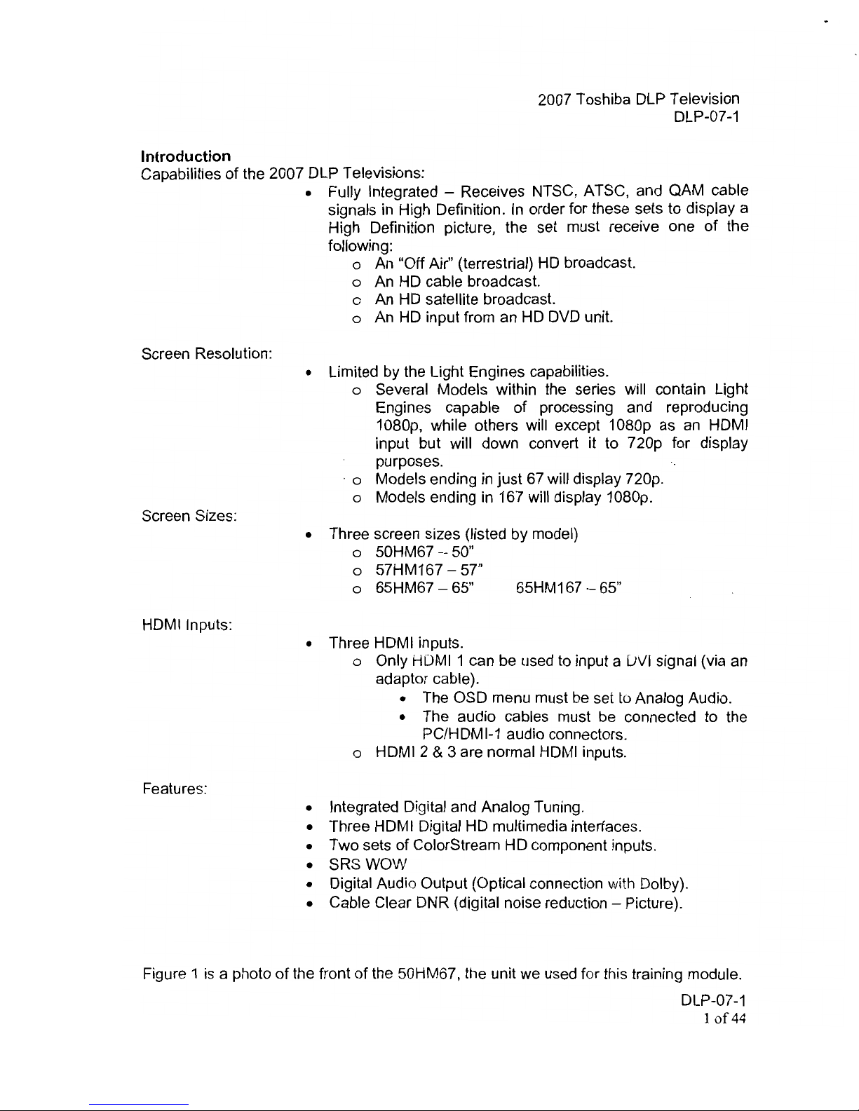
Figure 3 is a photo showing screw proximities to aid in removing the back cover.
DLP-07-1
20f44
Page 4
----
2007 Toshiba DLP Television
DLP-07-1
Figure 3
Once the ten screws are removed from the back cover, we will see a split chassis much
like we have seen in the past. Figure 4 is a photo depicting a split chassis.
Split
Chassis
Figure 4
DLP-07-1
30f44
Page 5
2007 Toshiba DLP Television
DLP-07-1
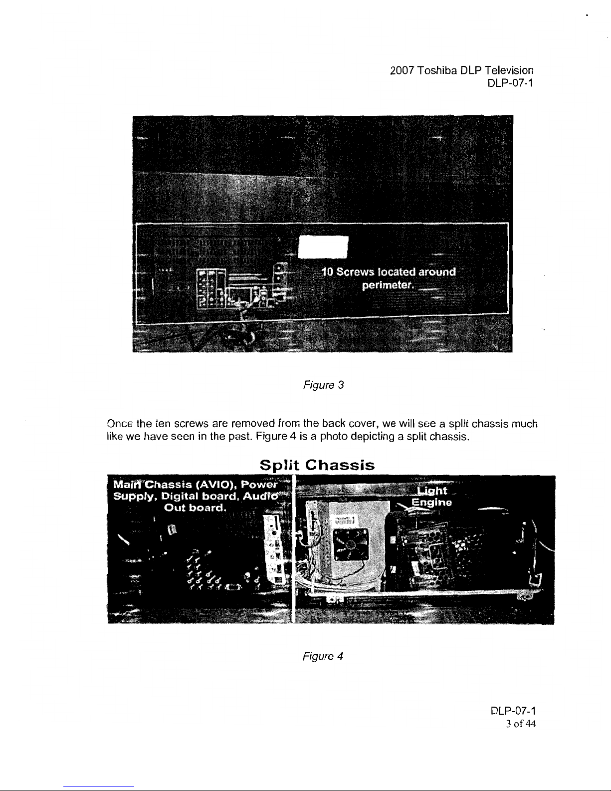
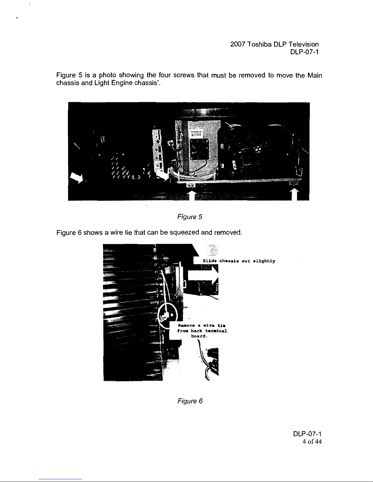
Figure 5 is a photo showing the four screws that must be removed to move the Main
chassis and Light Engine chassis'.
Figure 5
Figure 6 shows a wire tie that can be squeezed and removed.
Figure 6
DLP-07-1
40f44
Page 6
2007 Toshiba DLP Television
DLP-07-1
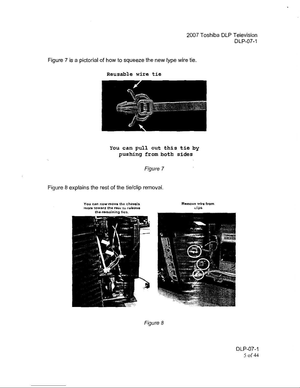
Figure 7 is a pictorial of how to squeeze the new type wire tie.
Reusable
wire
tie
You
can
pullout
this
tie
by
pushing
from
both
sides
Figure 7
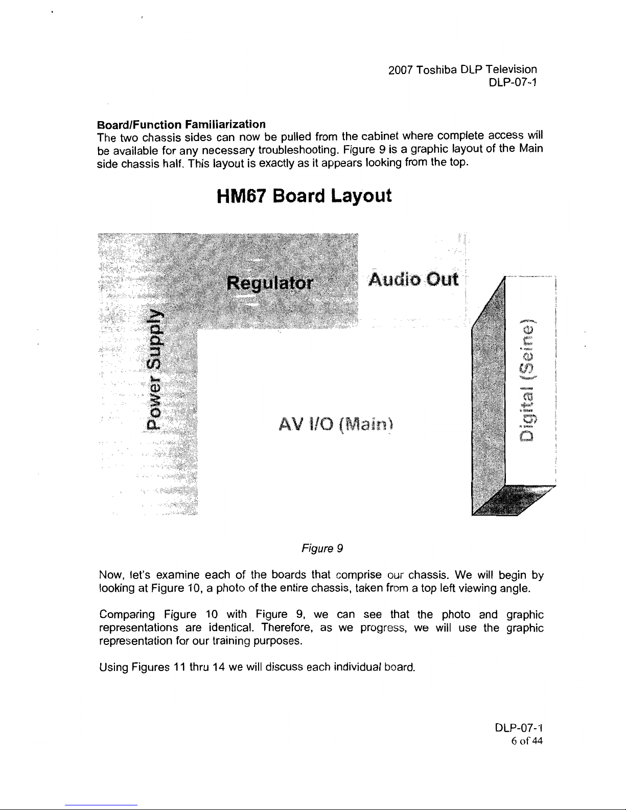
Figure 8 explains the rest of the tie/clip removal.
You
can
now
movill
the
cha1J!.Iis
Remove
",1m
from
more
toward
thlt
,eal'
tv
r .. 1;)lls0
"lip's
the
mma!ning
tics.
Figure 8
DLP-07-1
50f44
Page 7
2007 Toshiba DLP Television
DLP-07-1
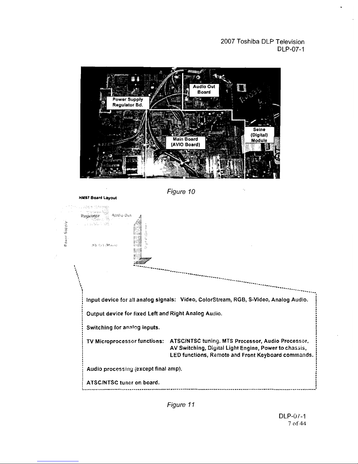
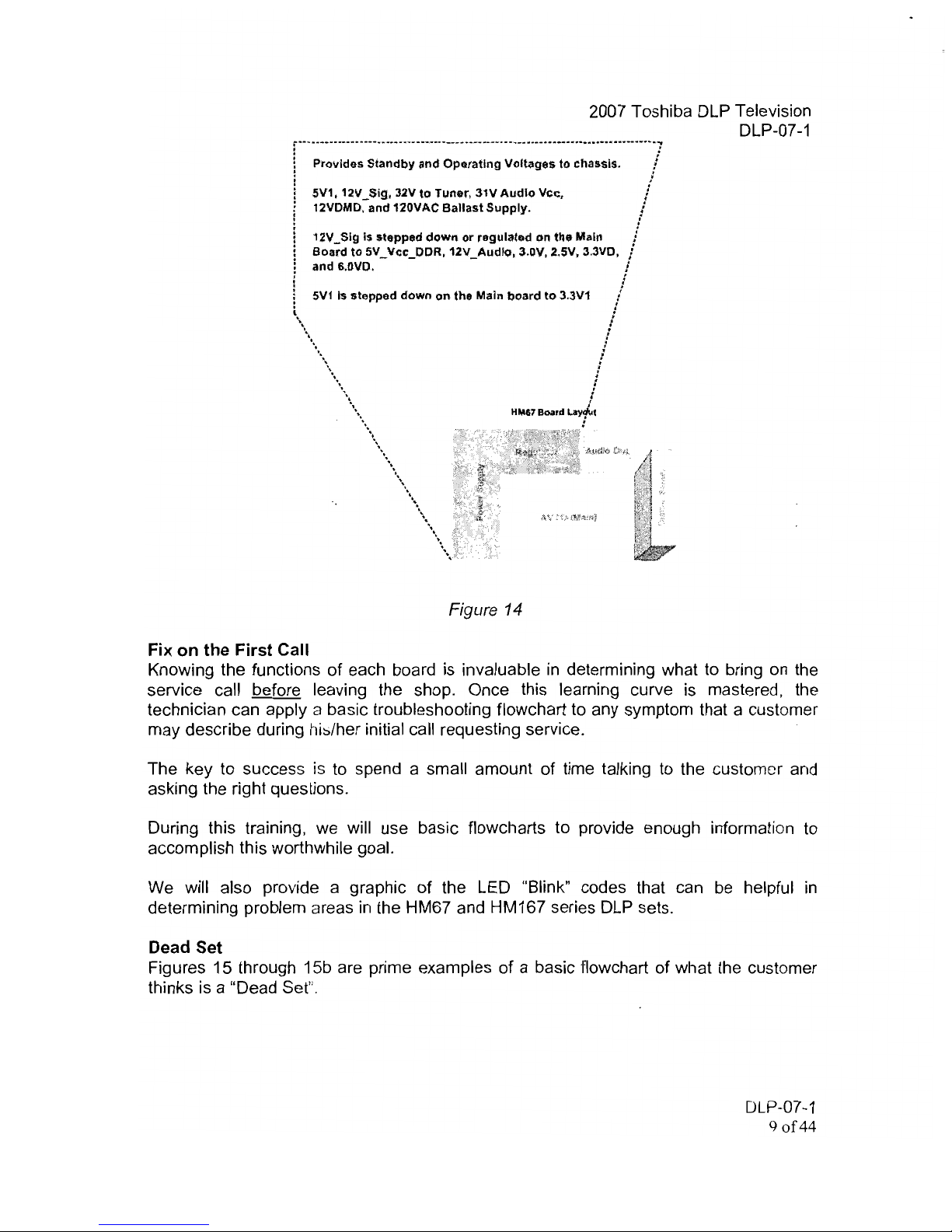
Board/Function Familiarization
The two chassis sides can now be pulled from the cabinet where complete access will
be available for any necessary troubleshooting. Figure 9 is a graphic layout
of
the Main
side chassis half. This layout is exactly as it appears looking from the top.
HM67 Board Layout
Audio
Out·
Figure 9
Now, let's examine each
of
the boards that comprise our chassis. We will begin by
looking at Figure 10, a photo
of
the entire chassis, taken from a top left viewing angle.
Comparing Figure 10 with Figure
9,
we can see that the photo and graphic
representations are identical. Therefore, as we progress, we will use the graphic
representation for our training purposes.
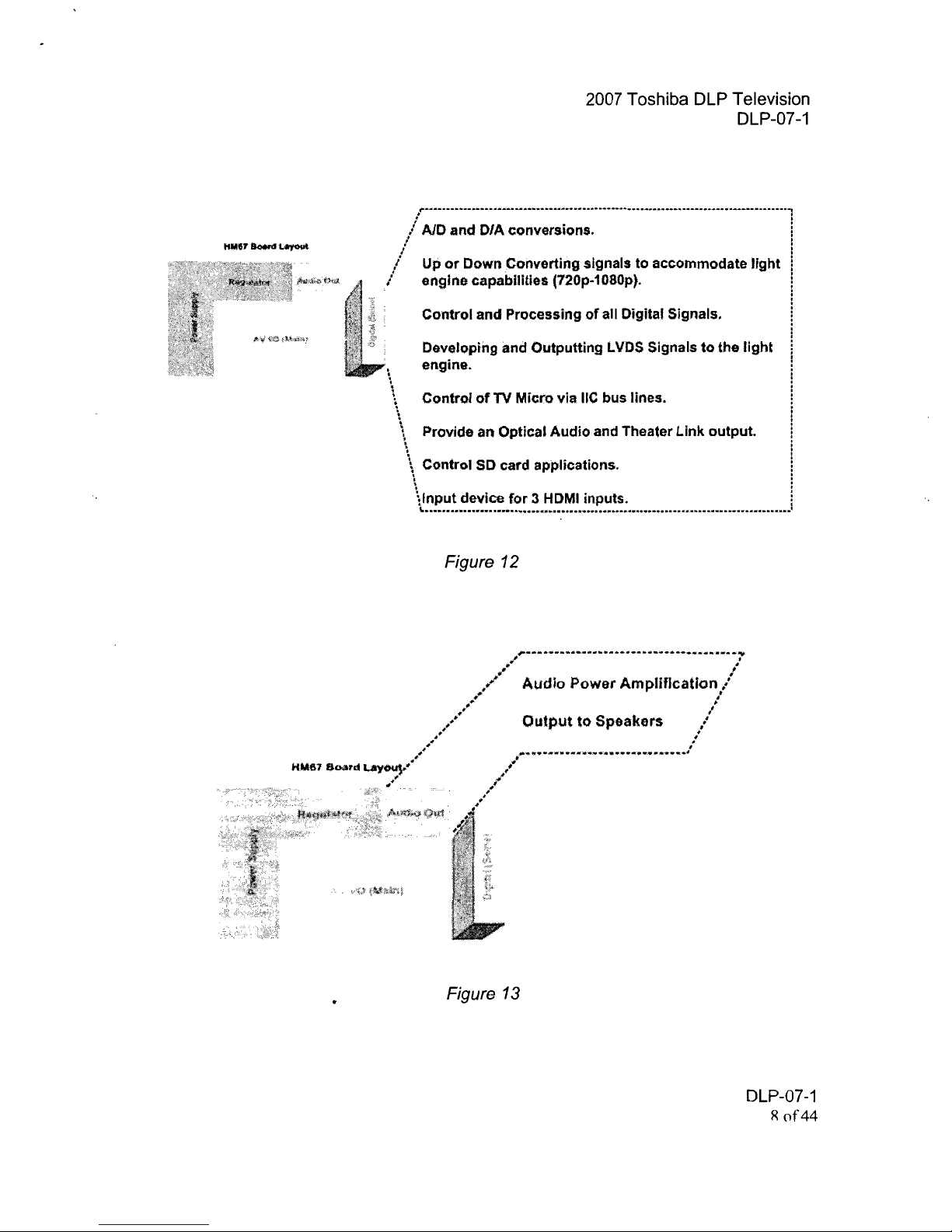
Using Figures
11
thru 14 we will discuss each individual board.
DLP-07-'1
60f44
Page 8
•
•
2007 Toshiba DLP Television
DLP-07-1
Figure 10
4
i5il
:;y
~.~
~.·.·:;.·I
~2
;:"f>%
i
':l
~---;-~.,:q
t'l
~"l
'i·
..
~.
~'
\
.
"
.
.
............................
__
........._......_.............._..................
"
...
-
..
-
·
·
·
·
'1
Input
device
for
all anaiog signals; Video, ColorStream,
RGB,
SNideo, Analog Audio.
•
:
•
·
:
Output
deVIce
for
fixed
left
and
Right
Analog Audio.
:
·
t
:
Switching
for
an;\!og inputs.
·
•
,
:
,
TV
MicroprocessorfuncUons:
ATSCINTSC tuning.
MTS
Processor, Audio Processor, !
AV
Switching, Digital
light
Engine, Power
to
chassis, !
LED functions, Remote and Front Keyboard commands. !
•
•
:
Audio
processinu
(except final amp).
·
·
:
:
ATSC/NTSC
tuner
on board.
·
,
·
•
~
...
,..
................
"".",,
...
""'
...._ ......... _.. _ ..
"'..................................... ft·,..."'
.. ,............. _......."".....
""
.................
""
.............. __...................... "'........_ ......_ ..._ ..-...
,..
.................. __....~...........
.
Figure
11
DLP-07-1
70f44
Page 9
2007 Toshiba DLP Television
DLP-07-1
~-
....--..-......
- ................ -
.........
-*""
................"'.........................................
--",
...~.....-.......-....
",
............."".....................
""t
. .
/ AID and DIA conversions. i
l :
/ i
I Up
or
Down Converting
81gnals
to accommodate
light
l
I engine capabilities (720p·1080p). !
Control and Processing
of
all Digital Signals. !
j
i
Developing and Outputting
LVDS
Signals to the light '
I,
engine.
\
\ Control
of
TV Micro
via
lie bus lines. !
i
\
\
\.
Provide
an
Optical Audio and Theater Link output.
.
!
;
;
\ Control
SO
card applications. !
\
\Input device
for 3 HDMI
inputs. !
~
~
••-......-..................."'...............................-...............« ....-....
-.-
............."".................
""
............................
.
Figure 12
_1T',.·""'*
..
1i'·
.......
·"'·"''''IIO
.......
_IW>~
......
''''
...
--~lf>
.............
1'
#~
.
;t
••
"
Audio
Power AmplifIcation
...
, I
*",.,.
I~
/
Output
to
Speakers
:'
, I
, .
1/1##~
..............
""'/Of
.........'...................................
#l
H.Mfi1
eo.wd
~."
-.#."•••
Figure
13
DLP-07-1
R
of44
Page 10
2007 Toshiba DLP Television
DLP-07-1
f
..........-_..................................
"'
.....
_-,."'
.......-.........-....-_.......................
-
............-_..........
iii
....
..
"''''··-7
,.
-
! Prollides Standby and Operating Voltages
to
char.sls. !
·
; :
.
· .
i 5V1. 12V _
$i9,
32V
to
Tuner, 31V
Audio
Vcr;,
,I
• 12VDMD.
and
120VAC
Ballast
Supply.
•
i
!
12V_Slg Is stepped
down
or
regulated
On
til"
Mail! i
l
!
Board
to
5V_Vcc_DDR.12V_Audlo.
3.0V. 2.SV. 3.3VO. J
: and 6.nVO. i
: :
: 1
i
5V1
Is stepped
down
on
the Main
board
to
3.3V1 /
·
• •
.
\
. ,
!
. .
\ :
\
,
,
.
I
,
\ 1
\ i
\\
.
HM87 Board
t.ay/ut
.
\\
.
'Ii",-,.
...
\\
•.
~\
\\
,)
"',o'
Figure
14
Fix
on
the
First
Call
Knowing the functions of each board is invaluable in determining what to bring
on
the
service call before leaving the shop. Once this learning curve is mastered.
the
technician can apply a basic troubleshooting flowchart to any symptom that a customer
may describe during
hi:::./her
initial call requesting service.
The key to success
is
to
spend a small amount of time talking to the
custom~r
and
asking the right questions.
During this training,
we
will use basic flowcharts to provide enough information to
accomplish this worthwhile goal.
We will also provide a graphic of the LED "Blink" codes that can
be
helpful
in
determining problem areas
in
the HM67 and HM167 series
DLP
sets.
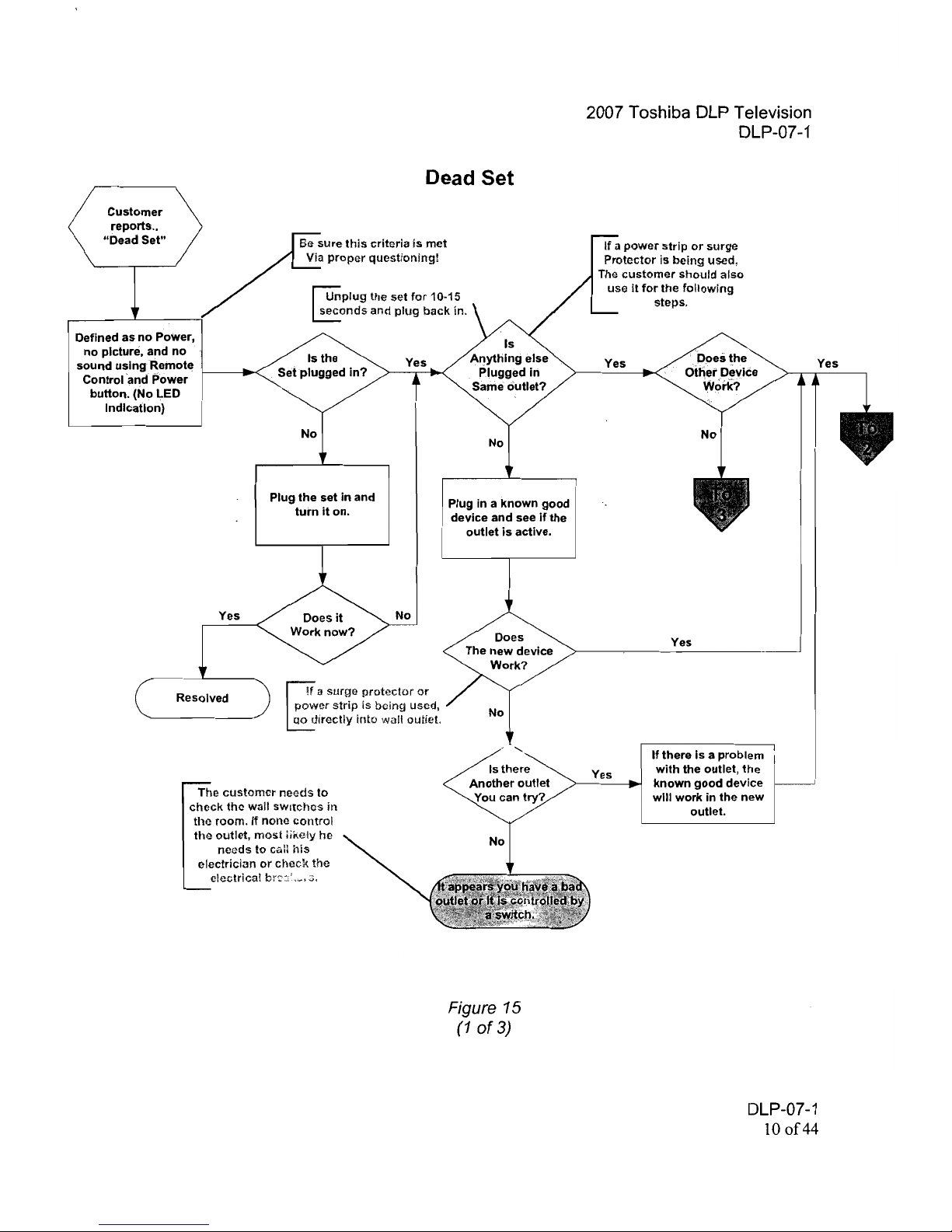
Dead Set
Figures 15 through 15b are prime examples of a basic flowchart of what the customer
thinks is a "Dead Set".
DLP-07-1
q
of44
Page 11
i
Dead Set
Customer
reports
..
"Dead
Set"
rt:!nplug
the
set
for
10-15
Eonds
and
plug
back in.
Defined
as
no
Power,
:
no
picture,
and
no
Is the
Yes
sound
using
Remote
Set
plugged
in?
C.
ontral'and.··
Power
f--_.-<
I.
button.
(No LED
Indication)
No
Plug
the
set
in
and
Plug in a
known
good
tum
it
on.
device
and see
if
the
outlet
is
active.
Yes
Does
it
No
Work
now?
Does
The
new
device
Work?
Resolved
J
a
surge
protector
or
power
strip
is
being used,
No
QO
directly
into
wall outlet.
~
Is
there
Another
outlet
The
customer
needs
to
check
the wall sWitches
in
the
room.
If
none
control
the
outlet,
most
liKely he
needs
to
cail
his
electrician
or
check
the
electrical
br::;:'._.::;,
Figure 15
(1
of
3)
2007 Toshiba DLP Television
DLP-07-1
If a power
strip
or
surge
Protector
is
being
used,
The
customer
should
also
use
II
for
the
following
steps.
Yes
Yes
Yes
If
there
Is a
problem
with
the outlet,
the
Yes
known
good
device
will
work
in
the
new
outlet.
DLP-07-1
10 of44
Page 12

2007 Toshiba DLP Television
DLP-07-1
Dead Set
(Continued)
Insure the Following Steps are Taken
Plug the TV Into the
Outlet
used
for
The
second
Device.
Does
It
Yes
Work
now?
No
Power
Supply
(1
s
'
Choice)
Main
Modul~
(2
nd
Choice) )
Figure 15a
(2
of
3)
DLP-07-1
11
of44
Page 13

2007 Toshiba DLP Television
DLP-07-1
Dead Set
(Continued)
Insure the Following Steps are Taken
If a surge
protector
or
power
strip
is
being
used.
plug
directly
into
the wall outlet.
Does
It
Yes
Work now?
Have Customer
No Replace power
strip
Plug
in
a known good
device and see
if
the
outlet
is
active,
The
customer
needs to
check.
the
wall
switches
in
the room,
If
none
control
the
0'.:::";:,
,nost
likely
he
No
Power Supply
nGGds
to
call
his
(1" Choice)
1;IIectricI,,'1
or
check the
electrical breakers.
It
appears the customer
has a bad outlet
or
it
Is
controlled by a switch.
Main Module
(2
nd
Choice)
Figure 15b
(3
of
3)
DLP-07-1
120f44
Page 14

2007 Toshiba DLP Television
DLP-07-1
Video Problems
Figures 16 through 16e will walk us through several paths involved
in
analyzing video
problems.
c
ust;;-";;';;-~-l
Symptom
No
Picture..or
i
BadPictur~
Distorted
Picture
No
Picture?
Or
Distorted
Picture?
No
Video
No
Picture
is
defined
as a
completely
black
or
completely
white screen.
Is
there
A
menu
when
the
Menu
button
is
Pushed?
No
~"'"
Digital
(Seill~
Yes
noisy,
poor
quality,
or
color
problem.
Have the
customer
make
slIre
the
lamp
il; lit.
Tilis
can
00
seen
by
looking
Ihrought
the
lamp
door
louvers
at
thot>
rear
of
the
Sdore
moving
on,
have
(he
customer
ltnplug
the
set
for
'\O-1!,
seconds
and
plug
back
in,
Which
input(s)
,
have
no
picture?
Select
Video Problems
Smudges,
Blotches.
spot!>, etc. are
most
likely"
pm!;le!'n
in
the
Ught
Palh.
Press uMenu".
Which
Input(s)
Is
it
Distorted?
Are
Distorted?
Yes
Select
Is
just
the
Menu
No
Distorted?
Yes
I
~------~---r---
Select
one
(based
on
customers'
answers)
I
Make
sure
the
~k;;ure
the
Make
sure
the
Make
sure
the
source
devie"
source
cables
are
source
cable
is
I
Signal
cable
Is
and
cable
ar"
,
properly
connected
and
connected
and
hooked
up
and
!
connec
ted and '
contains
a
sign~1.
working.
working.
contain
signals. '
Figure 16
(1 of6)
DLP-07-1
13
of44
Page 15

2007 Toshiba DLP Television
DLP-07-1
Insure the Following Steps are Taken
NTSC Only
ATSCOnly
Enter Menu
Yes
Enter Menu
EnsureJripot
is
Ensure
input
is
Properly'Set
for
i Propei1ySet
for
ANT.
ANT.
Main Module
1·t Choice
Select "Cablel
Antenna"
Select "Cablel
Antenna"
Confirm Channel
i
i
Confirm Channel
I'
Programming
Programming,
Is
No
Picture No
~
Ry~O~d1
(Mol"
~d:I:)
( Main Module
Yes
Resolved
Resolved
Figure 16a
(2
of
6)
DLP-07-1
140f44
Page 16

2007 Toshiba DLP Television
DLP-07-1
Insure the Following Steps are Taken
Note:
It
a OV!
device
is
being
used
via
an
adaptor.
with
the
HM67!167
series
sets,
the
input
MUST
be
on
HDMI1
and
the
Audio
Enter Customer
cables
MUST
be
connected
MimiJ
to
the
PC/HOMI 1
Inputs.
G
Select
HDMI1.
2,
or 3 (dopending
011
which
input
the
HDMI
cable
is
connected
to,
Ensure the
input
selection Is
properly set
in
[M,"'
"'"
th,
HOM.
'W'"
is
running
and
i,l
g,~od
the menu.
working
tHcler.
Is
No
Picture
Restored?
(Digital (Seine) Bd
Resolved
Figure 16b
(3
of
6)
DLP-07-1
15
of
44
Page 17

2007 Toshiba DLP Television
DLP-07-1
Insure the Following Steps are Taken
E"nter
Customer
Menu
Select
"AV1
or
AVZ"
Is
No
Picture
Restored?
Main
Module
Make
sure
there
is
flO
cable
plugged
into
the
S-Video jack..
Make sLlre the
Input
device
is
running
and
in
good
working
order.
Is
Picture
No
Restored?
Apply
signal
to
AV1
and
select
AV1
as
"Main
Input"
in
menu.
Is
No
Picture
Restored?
Figure 16c
(4
of
6)
DLP-07-1
16
of
44
Page 18

2007 Toshiba DLP Television
DLP-07-1
Insure the Following Steps are Taken
Enter
Customer
I Menu I
j-
Mak<:!
sure
the
Input
device
is
running,
in
good
working
ordor
and
connected
to
the
selection
Select Video-1, 2
made
in
iI,is
sl"p.
or
3 (Depends
on
I Menu and
input
being
used)
Is
Yes
Picture
No
Restored?
If
S-Video
is
o~r~~(~
panel
only,
change
front
panel.
For
Rear
mounted,
Change Main Module.
Figure 16d
(5
of
6)
DLP-07-1
17 of44
Page 19

2007 Toshiba DLP Television
DLP-07-1
Insure the Following Steps are Taken
Enter
Customer
Menu
The
solection
of
ColorStream-1
or
2 is
d&pendent
on
where the
ColorStream
input
cables
Select
are
connected,
ColorStream
1
or
~
2 (HD 1
or
HD2)
Mskio
sura the
Input
device
is
running
and in
good
working order.
CS2
Is
Is
No
Picture
Yes Yes
Picture
No
Restored?
Restored?
Resolved
Main
Module
Figure 16e
(6
of
6)
Audio Problems
Figures 17 through 17 e will
wc:llk
us through several paths involved in analyzing audio
problems.
DLP-07-1
18 of44
Page 20

2007 Toshiba DLP Television
DLP-07-1
Sound
Sound
Problems
Problems
HM67/167
Distorted
Distorted
Sound
No
Sound?
lathere
Sound
is
defined
as
a
Depress
the
Mute;
Or
Distorted
l
noisy
or
poor
button
on
the
Distorted
Sound
quality
type
of
Remote
Control.
Sound?
Now?
problem.
No
No
Sound
We
have
just
No
Sound
is
determined
the
"k"
sur"
the
Sound
Source
f'S
a
good
ch:t:lO
defined
as
a
Distortion
is
[:
input
signal.
complete
loss
of
coming
from
the
AUdio.
,
Signal
Path.
!
DSgable
tn'tt >¥P.tt(l,
Make
Sure
th"
Voium
..
satting
is
at
least
1-4
scal9
and
the
speAkor
selecUon
is
on
HJntetrtat"
OR
"0,,1',
Is
The
Mute
Yes
FUnction
Active?
No
IS
there
No
Sound
using
All
inputs?
·
Main
Module
No
~~ChOiCe)
C
Which
<
All
lnput(s)
have
No
Sound?
Select
Select
one
(based
on
customers'
answers)
Is
ita
Yes
Buzzing
or
a
Buzzing
Humming
Sound?
Figure 17
(1
of
6)
DLP-07-1
19 of44
Page 21

2007 Toshiba DLP Television
DLP-07-1
Insure the Following Steps are Taken
E
I
When the
choice
is
"Antanna",
a weak signa!
may
calise
sound
to
mute
THIS
IS
NORMAL!
Make
Sm"
the
Volu",.
setting
is
at
least
:i;,
scale
and
the
speaker
selection
is
on
"Internal"
OR
"On",
Enter CUstomer
Menu
Ensure Input
Is
properly set
for
Cabie
or
ANT
Select "Cablef
Antenna"
Confirm Program
Tuning
Resolved
Figure 17a
(2
of
6)
Main Module
DLP-07-'1
200f44
Page 22

2007
Toshiba DLP Television
DLP-07-1
Insure the Following Steps are Taken
Make Sure
the
Volume
setting
is
at
least
Y,
scale
and
the
speaker
selectiNl
is
on
"Internal"
OR
"On",
f
a
OVI
source
is
beino
used, make sure the 'l'!l'lio
cables are coon"c;te-:l
properly
(double-ch~r)'),
~
Enter Customer
Menu
Select
"HDMI1,
2,
or
3"
Make sure the
source is actually
HDMI and
NOT
DVI using an
adaptor.
Is
Sound
No
Restored?
Main Module
Resolved
Figure
17b
(3
of
6)
Make
sure
the
source
device and cable ore
hooked
up
properly and in
working
order.
HM67!1S7
When using A DVI
source
with
an
adaptor, the
only
input
that
can
be used
i",
HOMl'! and the
audio
cables
MUST b,l
connec;ted
to
PC/HDMI1 inputs;,
DLP-O/-1
21of44
Page 23

2007 Toshiba DLP Television
DLP-07-1
Insure the Following Steps are Taken
Select
the
input
that
was
the
cause
of
the
symptom.
Double
check
the
audio
connections
for
correctness.
Enter
Customer
Menu
Select "AV1
or
AV2"
No
Main
Module
Resolved
Figure 17c
(4
of
6)
Make Sure the Volume
setting
is
at least 'h scale
and the speaker selection
is
on
"Internal"
OR
"On".
DLP-07-1
22
of44
Page 24

2007 Toshiba DLP Television
DLP-07-1
Insure the Following Steps are Taken
.
Enter
OSD Menu
E
Make Sure thu
Volume
setting
Is
at
least~l,
scale
Make sure
the
audio
ami
the
speaker
~('!ecti()n
cables
are
plugged
into
tno
is
on
"Internal" OR
"On".
jacks
in
the
Video
2
section.
Select
"S-Video"
Or AV1.
Is
Sound
No
Restored?
Main Module
Resolved
Figure 17d
(5
of
6)
DLP-07-1
23
of
44
Page 25

2007 Toshiba DLP Television
DLP-07-1
Insure the Following Steps are Taken
enter aSD Menu
Make Sure the
Volume
IS
...
,tth.
Inp", that
W~
setting
is
!It least % seal,.
the
cause
of
the
symptom.
and the speaker selection
is
011
"Internal"
OR
"011".
Double
check
the
Audio
connections
for
.Selel.:t
correctness.
"ColorSbeam
1
or
2,"
Resolved
Figure 17e
(6
of 6)
Error Codes
Figure 18 is a graphic
of
the LED "Blink" codes used
in
the
2007, HM67/167 series DLP
sets.
DLP-07-1
24 of44
Page 26

2007 Toshiba
OlP
Television
OlP-07-1
LED
Specifications
(2007 DLP}
e
<V
~/®
~
Blinking
o
Off
ILED
Colors
Blue
Yellow
Red/Green
Voice
STATUS POWER
LAMP
Alert
1 Power
Off
(No AC)
o o o
2 Power
Off
(Standby)
o
o
o
3 Power On
o o
4 Power On -
Active
Standby
o o
®
5 Standby -
Quick
Restart On
o
o
6 Waiting
for
Lamp Start
o
7 Lamp
Won't
Light
o
YES
8 Lamp
Door
Open
YES
o
*
o
9 Fan Stop Detection
o
o
YES
10 IIC Bus
Error
(Light
Engine)
+ 0
YES
Slow
11
IIC
Bus
Error
+ Slow 0 0
12 Power
Protect
Detection +
Fast
0 0
---------------r---+~---r--------4_--_r~---r--~
}-< 0
~
13
Color
Wheel
3top
-,.v- Fast
~
YES
14
Thermo
Sensor
YES
+ * *
Fast
15 Seine
Booting
-#,..._
3 0
o
}*<
Times
16 Upgrade
in
Progress
o
17 Upgrade
Successful
o
o
18 Upgrade Failed
o
o
Figure 18
Used prior to
or
in conjunction with the flowcharts, while talking with the customer, the
error code blink sequence is another aid in making the right decision on what part/parts
to leave the shop with.
DlP-07-1
250f44
Page 27

2007 Toshiba DLP Television
DLP-07-1
Model
to
PCB
Chart
Figure
19
is a chart indicating Board names across the top, model numbers down the
left side and part numbers that intersect the model number and board name.
This will be helpful when you decide which section
of
the set is causing the symptom, i.e.
analog, tuning, system control, digital, optical, power supply, or aUdio/audio output.
Model
Power
Main
Light
Eng.
Seine
Audio
Out
50HM67
75006603
75007557 75006624
75007554 75006604
57HM1171167
75006603
75007558 75006657 75007555 75006604
65HM117/167
75006603
75007559 75006693
75007556 75006604
Replacement Seine
modules
will
include
any
option
code change
instructions
if
needed
Figure 19
Plan B
Realizing no flowchart can
be
perfect, pre-call analysis may sometime fail, and the fact
that some customers can't or won't cooperate
on
the phone, we will obviously have to
make a service call blind or troubleshoot the
SEt
because the board we det&; mined to
be the cause
of
thp symptom did not fix the set.
To assist us
in
troubleshooting we have developed a wiring interconnect diagram
showing the full-run voltages, connector numbers, pin numbers,
and
voltage derivation.
We also have a physical layout
of
the connectors
as
you would view them when
troubleshooting the chassis'. Figure 20 is a graphic showing the wiring interconnect, fullrun voltages, their derivation, and direction
of
application. It also contains indications
of
the standby voltages (Power Save mode & Fast Start mode) that are present when the
set
is
in one
of
the standby modes. The letter "F" designates Fast Start and the letter "P"
designates Power Save.
DLP-07-1
26
of
44
Page 28

2007 Toshiba
DLP
Television
DLP-07-1
HM671167 Series
Wiring Interconnect
-Supply Voltages-
Formatter,
Ballast
&
Light Eng
.........................................
_-_
....
l
Standby
Voltages
!
: [F) =F
asl
Start
Mode
:
: IPJ
=
Power
Save
Mode
:
\,
..............
"'
.....................
--
....
--"
....
,
~_cs_perived
From
. r 12V_Sig
• •
5V1
.
.
.
SV1 > 3.3V1 > 2.SV
Direction
of
Arrows
-+-
Indicates
direction
the
Signal
or
source Is
being
.........
Appl1ed from.
-
CO
:::
C)
.-
C
[F)
[F)
-
(I)
[F)
C
[F]
(I)
(/)
[F]
IF)
[F)
IF)
IF)
IF)
IF)
IF)
[FJ
IF)
[F)
[F)
[F)
Figure 20
DLP-07-1
27
of
44
Page 29

--
2007 Toshiba DLP Television
DLP-07-1
Figure
21
is a graphic
of
the physical layout
of
the connectors mentioned above.
Board Layout & Connector Placement
HM67/167 Series
..
P.7tta,
AV
1/0
(Main)
Connector
From
I
To
Pin Numbers & Voltages - FULL RUN MODE
PV2SA
Main
SideAV
P·i
(2.4V)
PB93A
Majll
SideAV
P.i.
P2. P3 (3.3V)
PB92A Main Front..t.ED
P·i
(S.OV),
P·2
(3.0V)
P70GB Main
Light Engine
P·i
(3.3V). P-3 (2.0V), P-4
(2.5V)
PBSOA
taB
Power
Main
P·2
(3.0V).
P·3
(2.5V). P-6, P·7,
IS.OV).
P·17.
P·i8.
Pi9,
P20. (i2.0V). P·23
132V)
P8i2
Power
Formatter
P·i,
P2. (12.0V)
P8iA
to
B
Power
Audio
Out
P·i.
P2, P3, P4
(31.OV).
P·9
(S.OV)
PB60A
to
B
Main
Audio
Out
P·2
(4.5V). P-6
(4.SV)
• Pi0G
Audio Out
Speakers
PB504 Main
IR
Board P-4
(S.OV).
P·5
(4.2V)
PE80
Main
Seine
P·i
(i2.0V), P-4
(S.OV),
p·s
(S:OV),
P·9,
Pi0,
P1i
(3.3V)
PBi0i
Main
Seine
P-4 (3.2V)
PB102
Main
Seine
P-4 (4.0V),
P·5
(4.0V), P20
(3.3V)
PB103
Main
Seine
P·13
(3.3V),P.i4
(3.3V),
PiG,
Pi8,
P20
(2.GV),
P22
(2V)
-
P777B
Main
Light Engine
P·2, P-3. P-4,
p·s
(3.2V), P·7 (2.9V), P·9 (2.9V)
P807
Power
ILight Engi,,"
P·1
to
P·2 (120VAC)
Legend:
p
Power
Supply/Regulator Board
AVID/Main
Board
Audio Output Board
,
Seine/Digital
Board
c=
..
_.
Indicates Pin
#1
1'"\ n
n"7
..
28
of
44
v
Page 30

2007 Toshiba DLP Television
DLP-07-1
Figure
21
Figure 22
is
a chart showing the voltages present on
the
connectors during Standby
when the set
is
in the "Power Saving" mode (Customer Menu Selection).
Standby
Voltages in Power Savings Mode
Connector
From
To
Pin
Numbers & Voltages
- STANDBY -
Power
Save
Mode
PB93A Main
SideAV
P-1, P2,
P3
(3.3V)
PB92A
Main Front-LED
P-1
(S.OV)
P706B
Main
Light
Engine
P-1 (3.3V), P-4 (2.5V)
~toB
Power
Main
P-6, P-7
(S.OV),
P-23 (30-32V)
Cpa1A
to
B
Power
Audio
Out
P-9
(S.OV)
PBS04
Main
IR
Board
P-4 (5.0V). P-S (4.2V)
Figure 22
Figure 23 is a chart showing the voltages present
on
the connectors during Standby
when the set
is
in the "Fast Start" mode (Customer Menu Selection).
Standby
Voltages·
Fast Start Mode
Connector
From
To
Pin
Numbers & Voltages
- STANDBY -
Fast
Start
Mode
PV25A
Main SideAV
P-1
(2.4V)
<-
PB93A
Main
~ide
AV
P-1, P2, P3 (3.3V)
PB92A
Main Front-LED
P-1
(5.0V)
P706B Main
Light Engine
P-1
(3.3V). P-4 (2.5V)
--<---------
PB80A
to
B Power
Main
P-3
(2.5V), P-6, P-7,
(5.0V),
P-17. P-18, P19, P20, (12.0V). P-23 (31V)
P81A
to B
Power Audio Out
P-1, P2, P3, P4
(31.0V),
P-9
(5.0V)
,
PB60A
to
B
Main
Audio Out
P-2
(4.5V), P-6 (4.5V)' P-8 (2.7Y'l.J::lUPV)
PB504
Main
IR
Board
P-3
(3.2V). P-4 (5.0V),P-5
~V)
PE80
Main
Seine
f':1l1~:116'()V)L!,:5
(5<OV),
P·9, P10,
P11
(3.3V)
PB101
Main
Seine
P-2
(3.2V),
P-4
(3.2V)
..
PB102
Main
Seine
P-4 (4.9'.').
p-s
{4.0'.'), P-16
(32"LP20
(3.3V)
PB103
Main
Seine
P-13 (3.3V). P-14J3.3V), P16, P18, P20 (2.6V). P22 (2.3V)
Figure 23
Switched
Voltages
(Main
Board)
There are several voltages derived from the power supply that are developed
on
the
Main Board. Figure 24
is
a block Diagram showing those voltages
and
Protect Circuits.
DLP-07-1
29
of
44
Page 31

3.3V1
3.3V1
3.3V1
3.3V1
Prote"t
Power
Powe,-OB_Oet
12V
2007 Toshiba
DLP
Television
DLP-07-1
Main Board
Switched
& Regulated Voltages
&
Protect Circuits
3.3V1
SV1
3.3V1
..
ICOS
..
Door
Switch
12V
AC_Oet
Powe,-Sig_Oet
IC830
3.3VO
PROTECT
IC831
6VO
VCC_OOR
IC832
SV2
9V
Figure 24
DLP-07-1
300f44
Page 32

2007 Toshiba DLP Television
DLP-07-1
Implementing Plan B
Plan B becomes necessary for a number
of
reasons; however, they all boil down to one
basic procedure.
That
is, the set needs to be repaired and some troubleshooting needs
to be implemented. "Dead Set" flowcharts 2 and 3 (previously covered) will be used to
demonstrate this procedure.
The 2007 DLP sets have
two
power settings; "Power Saving" and "Fast Start". When a
Dead Set condition is encountered, we have no
way
of
confirming which power setting
was being used by the customer. Therefore, two charts were developed to aid in
determining the cause
of
our "Dead Set". Those charts are on page 29 and are labeled
Figure
22
and Figure 23.
The two voltage charts, used
in
conjunction with the two flowcharts mentioned above,
will be used to determine which board/boards is or could be the cause
of
our dead set.
Note: When a set is placed
in
the "Power Saving" mode, the only voltages made
available to the chassis are the voltages necessary for a basic standby condition. That
means the
TV
micro, EEprom, IR receiver, Light Engine" micro, and front LED supplies.
When a set is placed in the "Fast Start" mode, almost all
of
the "Full Run" voltages are
made available to the chassis during standby. This feature allows the Seine module to
remain in the "booted" condition. There will be
no
time delay to allow the Seine module
to "boot-up". This provides
us
with a fast start-up but uses a bit more power when idle.
Flowchart 2 will be labeled Figure 25 &
26
and will be used to provide a troubleshooting
example in each
of
the two "start" modes.
Flowchart 3 will be labeled Figure 27 &
28
and will
also
be used
80
an example in each
of
thp two "start" modes.
DLP-07-1
31 of44
Page 33

2007 Toshiba DLP Television
DLP-07-1
Supplement
to
"Dead
Set"
- DLP-07-1 - Page
11
Dead Set
(Continued)
Insure the Following Steps are Taken
Fast
Start
Mode
Plpgthe
TV into the
Outlet psed
for
The
secol1d Device.
Plan HB"
occurs
when a
service call
is
made and
a replacement part
is
not
on site
OR
when
confirmation
is
desired
Does
it
Yes
prior
to replacement.
Work now?
Plan B
No
.1--
1
Power Supply
(1'1
Choice)
No
5V
PB80
1-
-
Pins
6 &
7?
I
~.
Main Module
Yes I
Power
Supply
(2"d Choice)
2.6V PB80
No
Pin 3?
--
I
I
Yes I
Main Module
+
r
(
!
)
Push Power
Yes
No
I--
Button.
--I
3VPB80
I
I
~n2
(
!
)
',,/
Power Supply
Main Module
Figure 25
DLP-07-1
320f44
Page 34

2007 Toshiba DLP Television
DLP-07-1
Supplement
to
"Dead
Set"
- DLP-07-1 - Page
11
Dead Set
(Continued)
POWER SAVINGS
Insure the Following Steps are Taken
MODE
Plan
"S"
occurs when a
service call is made and a
Plug the TV Into the
replacement part
is
not
on
Outlet
used
for
The
second
Device.
site OR when confirmation
is
desired
prior
to
replacement.
Does
it
Yes
Work now?
PLANS
,-
- -
----
--
--
---
,
;-
- - On PB80
NO~~
,
P~s6&7?
(Main
Module
\..
(2""
Choice)
IYes
Power Supply
i
uShPower
No
Button.
~
-,
3V On
PBBO
Pin 27
,
, Yes
,
I
(~n-!::J
:~'-<i~?~:
",'
...
_.
-'!--~
Power Supply (
Main
Module)
Figure 26
DLP-07-'1
33
of
44
 Loading...