

Page 1

Outdoor
Installation Instructions
Air Conditioner – Multi Split Type System
Außengerät
Installationsanleitung
Klimaanlage – Geteilte Multi-Bauweise
Instructions
d’Installation Extérieure
Climatiseur – Système de Type Multi Split
Buiten
Installatievoorschriften
Airconditioning – Multi-delig Type Systeem
GB
F
D
E
I
NL
Istruzioni per
l’installazione dell’unità esterna
Condizionatore d’aria – Tipo Multi Split
Modular Multi System
Exterior
Instrucciones de Instalación
Aire acondicionado – Sistema de Tipo Multi Split
HFC
R407C
1402241301R01
Page 2

Page 3
GB
3
Contents
Introduction . . . . . . . . . . . . . . . . . . . . . . . . . . . . . . . . . . . . . . . . . . . .4
Installation . . . . . . . . . . . . . . . . . . . . . . . . . . . . . . . . . . . . . . . . . . . . .9
Trial Operation . . . . . . . . . . . . . . . . . . . . . . . . . . . . . . . . . . . . . . . .38
Troubleshooting . . . . . . . . . . . . . . . . . . . . . . . . . . . . . . . . . . . . . . . .48
Environmental . . . . . . . . . . . . . . . . . . . . . . . . . . . . . . . . . . . . . . . . .64
Passer à la page 65 pour lire le manuel d’installation en
français.
Die deutsche Montageanleitung finden Sie auf Seite 127.
Por favor, vaya a la página 189 para seguir las instrucciones del
manual de instalacíon en lengua española.
Il manuale d’installazione italiano è a pagina 251.
Zie bladzijde 313 voor de Nederlandse Installatichandleiding.
F
D
E
I
NL
Page 4

GB
Introduction
Contents
4
Precautions . . . . . . . . . . . . . . . . . . . . . . . . . . . . . . . . . . . . .5
Operating Conditions . . . . . . . . . . . . . . . . . . . . . . . . . . . . . .6
Components . . . . . . . . . . . . . . . . . . . . . . . . . . . . . . . . . . . . .7
Metric/Imperial pipe conversion . . . . . . . . . . . . . . . . . . . . .7
Page 5

GB
Please read these instructions carefully before starting the installation.
This equipment should only be installed by suitably trained operatives.
In all cases ensure safe working practice: Observe precautions for persons in the vicinity of
the works.
Ensure that all local, national and international regulations are satisfied.
Check that the electrical specifications of the unit meet the requirements of the site.
Carefully unpack the equipment, check for damage or shortages. Please report any damage
immediately.
These units comply with EC Directive:
73/23/EEC (Low Voltage Directive) and 89/336/EEC (Electro Magnetic Compatibility).
Accordingly, they are designated for use in commercial and industrial environments.
Avoid installation in the following locations:
Where the water drainage may cause a nuisance or a hazard when frozen.
Where there is a danger of flammable gas leakage.
Where there are high concentrations of oil.
Where the atmosphere contains an excess of salt (as in coastal areas). Special maintenance
is required to maintain product design life.
Where the airflow from the outdoor unit may cause annoyance.
Where the operating noise of the outdoor unit may cause annoyance.
Where the foundation is not strong enough to fully withstand the weight of the outdoor unit.
Where strong winds may blow against the air inlet of the outdoor unit.
Precautions for R407C Systems
R407C outdoor units use synthetic oils which are extremely hygroscopic. Therefore ensure
that the refrigerant system is NEVER exposed to air or any form of moisture.
Mineral oils are unsuitable for use in these units and may lead to premature system failure.
Use only equipment which is suitable for use with R407C. Never use equipment which has
been used with R22.
R407C should only be charged from the service cylinder in the liquid phase. It is advisable to
use a gauge manifold set equipped with a liquid sight glass fitted in the centre (entry) port.
5
Introduction
Precautions
Page 6
GB
6
Introduction
Operating Conditions
1. Allocation standard of Model name
2. Range of combined units
No. of combined units : 1 to 5 units
Capacity range : Equivalent to 14HP (0384kW type) to 46HP (1288kW)
3. Restriction for combination units
(1) The Inverter Unit should have the maximum capacity among all units in
that combination.
(2) The 6HP fixed-speed unit is available only with the combination of 14HP
and 22HP. (It cannot be used for any other combination.)
4. Rated conditions
Cooling : Indoor air temperature 27°C DB/19°C WB
Outdoor air temperature 35°C DB/25°C WB
Heating : Indoor air temperature 21°C DB/15.5°C WB
Outdoor air temperature 7°C DB/6° C WB
5. Mode Priority
This Outdoor Unit is set to operate with the Heating mode taking precidence. This
precidence can be switched between Heat and Cool mode using the DIP switch 07
on the Outdoor Unit Interface PCB (MCC-1343-01) as follows:
Outdoor Temperature
–5 ~ 43°C Cooling
–15 ~ 21°C Heating
Room Temperature
18 ~ 32°C Cooling
15 ~ 29°C Heating
Room Humidity <80% Cooling
T – Inverter
X – Fixed Speed
0280 – 28.0kW (10HP)
0224 – 22.4kW (8HP)
0160 – 16.0kW (6HP)
C – Cooling
H – Heating
MM–A0280HT
INDOOR
OUTDOOR
A – Outdoor
Modular Multi
028 – 2.8kW (1HP)
042 – 4.2kW (1.5HP)
056 – 5.6kW (2HP)
080 – 8.0kW (3HP)
112 – 11.2kW (4HP)
140 – 14.0kW (5HP)
MM–TU056
Modular Multi
B – Built-In Duct Type
C (CR) – Ceiling Type (IR Remote)
K (KR) – High Wall Type (IR Remote)
N – Carcase Type
S (SR) – Low Wall Type (IR Remote)
SB – Built-In Slim Duct Type
TU – 2 Way Cassette Type
U – 4 Way Cassette Type
ON
OFF
ON
OFF
Heat Priority (factory set) Cool Priority
Page 7
GB
7
Introduction
Components
Metric/Imperial pipe conversion
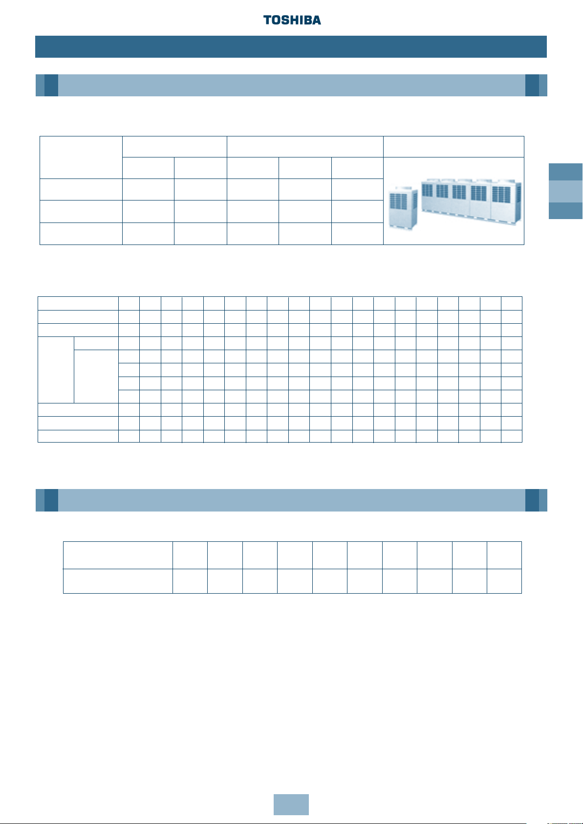
Inverter unit Fixed-speed unit Appearance
Corresponding HP
8HP 10HP 6HP 8HP 10HP
Model name MM-A0224HT MM-A0280HT MM-A0160HX MM-A0224HX MM-A0280HX
Cooling capacity (kW) 22.4 28.0 16.0 22.4 28.0
Heating capacity (kW) 25.0 31.5 18.0 25.0 31.5
Corresponding HP 8HP 10HP 14HP 16HP 18HP 20HP 22HP 24HP 26HP 28HP 30HP 32HP 34HP 36HP 38HP 40HP 42HP 44HP 46HP
Combined Model MM-A~HT
0224 0280 0384 0440 0504 0560 0608 0672 0728 0784 0840 0896 0952 1008 1064 1120 1176 1232 1288
Cooling capacity (kW) 22.4 28.0 38.4 44.8 50.4 56.0 60.8 67.2 72.8 78.4 84.0 89.6 95.2 100.8 106.4 112.0 117.6 123.2 128.8
Inverter unit 8HP 10HP 8HP 8HP 10HP 10HP 8HP 8HP 10HP 10HP 10HP 8HP 10HP 10HP 10HP 10HP 10HP 10HP 10HP
— — 6HP 8HP 8HP 10HP 8HP 8HP 8HP 10HP 10HP 8HP 8HP 10HP 10HP 10HP 8HP 10HP 10HP
— — — — — — 6HP 8HP 8HP 8HP 10HP 8HP 8HP 8HP 10HP 10HP 8HP 8HP 10HP
——— ————— ———8HP8HP8HP8HP10HP 8HP 8HP 8HP
——— ————— ————————8HP8HP8HP
13 16 16 18 18 20 22 24 26 28 30 32 34 36 38 40 40 40 40
Min. HP Connection 4 5 7 8 9 10 11 12 13 14 15 16 17 18 19 20 21 22 23
Max. HP Connection 10.8 13.5 18.9 21.6 24.3 27 29.7 32.4 35.1 37.8 40.5 43.2 45.9 48.6 51.3 54 56.7 59.4 62.1
Combined
outdoor
units
No. of connectable
indoor units
Fixedspeed unit
1. Outdoor Unit
2. Outdoor Units (Combination of Outdoor Units)
Diameter (mm) 6.4 9.5 12.7 15.9 19.0 22.0 28.6 34.9 41.3 54.1
Nominal Diameter (inch)
1
/4
3
/8
1
/2
5
/8
3
/4
7
/8 1 1/8 1 3/8 1 5/8 2 1/8
Note: 1.0MPaG = 10.2kgf/cm2G
Page 8
GB
8
Introduction
Components
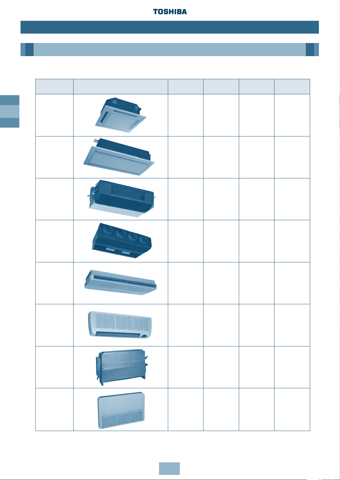
Type Appearance Model name Capacity code/
Cooling Capacity Heating Capacity
HP (kW) (kW)
MM-U056 2 5.6 6.4
MM-U080 3 8.0 9.6
MM-U112 4 11.2 12.8
MM-U140 5 14.0 15.8
MM-TU028 1 2.8 3.2
MM-TU042 1.5 4.2 4.8
MM-TU056 2 5.6 6.4
MM-SB028 1 2.8 3.2
MM-B056 2 5.6 6.4
MM-B080 3 8.0 9.6
MM-B112 4 11.2 12.8
MM-B140 5 14.0 15.8
MM-C/CR042 1.5 4.2 4.8
MM-C/CR056 2 5.6 6.4
MM-C/CR080 3 8.0 9.6
MM-C/CR112 4 11.2 12.8
MM-C/CR140 5 14.0 15.8
MM-K/KR042 1.5 4.2 4.8
MM-K/KR056 2 5.6 6.4
MM-K/KR080 3 8.0 9.6
MM-N028 1 2.8 3.2
MM-N042 1.5 4.2 4.8
MM-N056 2 5.6 6.4
MM-N080 3 8.0 9.6
MM-S/SR056 2 5.6 6.4
MM-S/SR080 3 8.0 9.6
4 Way Cassette
Type ‘U’
2 Way Cassette
Type ‘TU’
Built-In Slim
Duct Type ‘SB’
Built-In Duct,
Type ‘B’
Ceiling
Type ‘C’
High Wall
Type ‘K’
Carcase
Type ‘N’
Low Wall
Type ‘S’
3. Indoor Unit
Page 9

GB
9
Installation
Contents
Outdoor Unit
Transportation of the Outdoor Unit . . . . . . . . . . . . . . . . . . . . . . . . . . .10
Installation of Outdoor Unit . . . . . . . . . . . . . . . . . . . . . . . . . . . . . . . . .11
Dimensional Drawings Outdoor Unit . . . . . . . . . . . . . . . . . . . . . . . . . .12
Dimensional Drawings Two Units Connected . . . . . . . . . . . . . . . . . . . .13
Dimensional Drawings Three Units Connected . . . . . . . . . . . . . . . . . . .14
Dimensional Drawings Four Units Connected . . . . . . . . . . . . . . . . . . . .15
Dimensional Drawings Five Units Connected . . . . . . . . . . . . . . . . . . . .16
Multiple Installation on the Rooftop . . . . . . . . . . . . . . . . . . . . . . . . . . .17
Piping
Free Branching System . . . . . . . . . . . . . . . . . . . . . . . . . . . . . . . . . . . . .19
Connecting Refrigerant Pipes . . . . . . . . . . . . . . . . . . . . . . . . . . . . . . . .20
Permissible Length/Height Separation of Refrigerant Piping . . . . . . . .21
Selection of Refrigerant Piping and Charge Requirement . . . . . . . . . .22
Branch Headers/Branch Joints (Accessories) . . . . . . . . . . . . . . . . . . . . .24
Branch Header/T-shape Branch Joint . . . . . . . . . . . . . . . . . . . . . . . . . .25
Connecting the Branching Kit/Y-shape Branching Joint . . . . . . . . . . . .26
Heat Insulating the Branching Pipes/Branching Header . . . . . . . . . . .27
T-shape Branching Joint – to Connect Outdoor Units . . . . . . . . . . . . . .29
Installation of Gas/Liquid Branching Pipes . . . . . . . . . . . . . . . . . . . . . .30
Airtight Test . . . . . . . . . . . . . . . . . . . . . . . . . . . . . . . . . . . . . . . . . . . . .31
Leak Position Check/Air Purge . . . . . . . . . . . . . . . . . . . . . . . . . . . . . . .32
Calculating the Additional Refrigerant Required . . . . . . . . . . . . . . . . .33
Additional Charge Amounts . . . . . . . . . . . . . . . . . . . . . . . . . . . . . . . . .34
Wiring
General/Wiring System Overview . . . . . . . . . . . . . . . . . . . . . . . . . . . .35
Connecting Power Source Cable/Control Cable . . . . . . . . . . . . . . . . . .36
Control Wiring Overview . . . . . . . . . . . . . . . . . . . . . . . . . . . . . . . . . . .37
Page 10
GB
10
Installation
Outdoor Unit
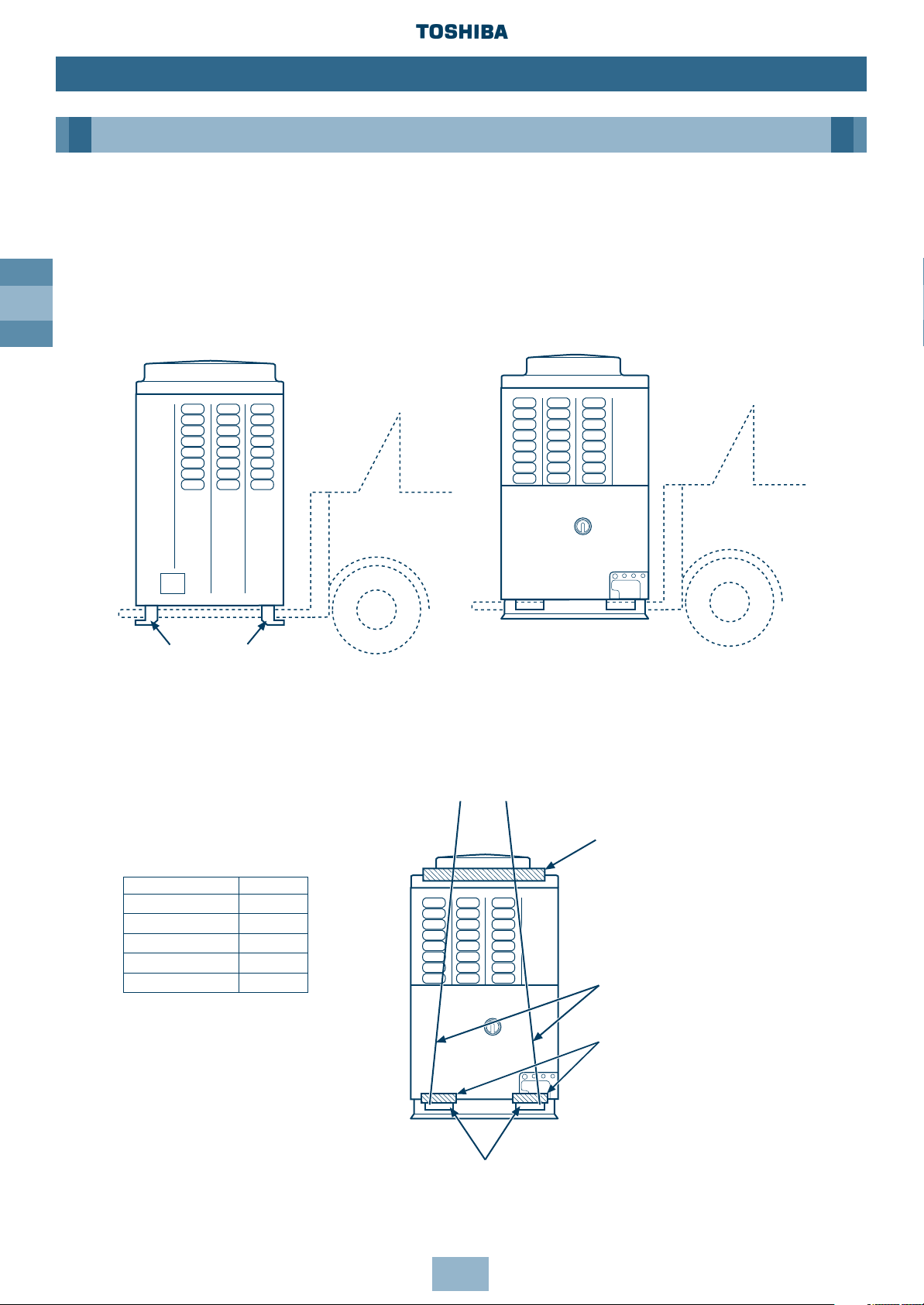
Transportation of the Outdoor Unit
Fork Lift
• Front Access – insert the forks into the slots on the fixing legs.
• Side Access – see diagram.
Fork lift
Fork lift/
Hand Truck
Transportation Slots
Protection
Fixing Leg
Protection
Rope
Crane
• Check the suitability of the lifting rope (see table).
• Secure lifting rope through transportation slot.
• Protect the unit where rope contact could scratch or deform it.
Model Weight
MM-A0280HT 284.0kg
MM-A0224HT 282.0kg
MM-A0280HX 280.0kg
MM-A0224HX 278.0kg
MM-A0160HX 204.0kg
Front Access Side Access
Page 11
GB
Installation
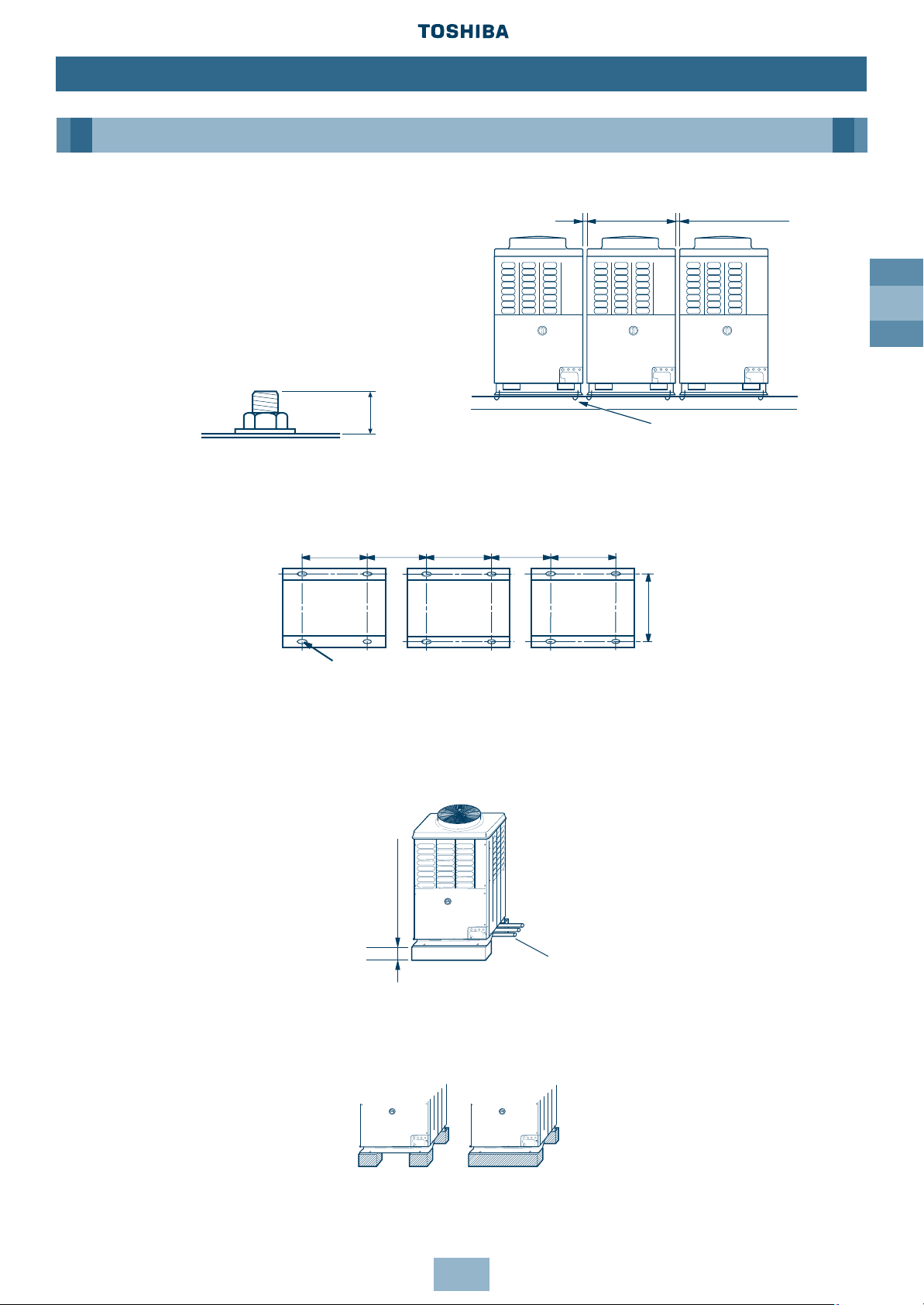
Installation of Outdoor Unit
1. Align the outdoor units at intervals of 20mm
or more.
Fix the outdoor units with M12 anchor bolts.
(4 positions per unit.)
Anchor bolt with 20mm length is suitable.
• Anchor bolt pitch is as shown in the following figure.
• However, the equivalent pipe length between the nearest outdoor unit and farthest outdoor
unit of the refrigerating cycle system should not exceed 20m.
2. When routing the refrigerant piping through the base, the fixing height of the base
(two-divided foundations) must be 500m or more.
3. Correct foundation mounts for supporting the Outdoor unit:
Note: The leading outdoor unit to be connected to the main refrigerant piping for the indoor
units must be an inverter unit.
Outdoor Unit
11
M12 anchor bolt,
4 positions per unit
≥ 20mm
700mm ≥ 310mm 700mm ≥ 310mm 700mm
755mm
≥ 500mm
20mm
≥ 20mm
15 x 20mm slot
Refrigerant Piping
✖
✔
Page 12
GB
12
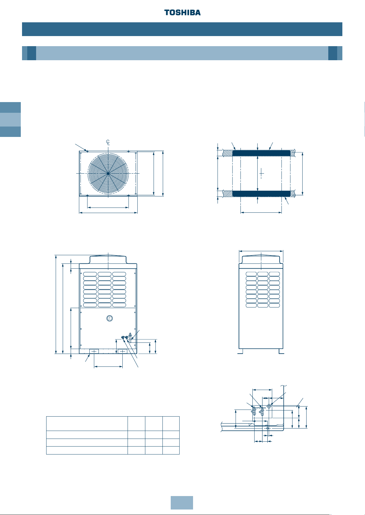
Dimensional Drawings
Outdoor Unit
Model Name:
MM-A0280HT, MM-A0224HT, MM-A0280HX, MM-A0224HX, MM-A0160HX
Installation
Outdoor Unit
700
990
790
500
1700
1560
700 9088
130
145
140
170
125
64
20
65
35
60
115
173
610 100
700
750
100
630 80
755
80
245
190
755
235
Model
ØA ØB ØC
mm mm mm
MM-A0280HT, MM-A0280HX 28.6 12.7 9.52
MM-A0224HT, MM-A0224HX 22.2 12.7 9.52
MM-A0160HX 22.2 9.52 9.52
4-15 x 20 (Slot)
Fixing bolt pitch
Fixing bolt pitch
(including fixed leg)
Grounding part
of bottom plate
Base
Fixing bolt pitch
Base
Fixing bolt pitch
Refrigerant pipe connecting port
(Gas side) braze connection (ØA)
Refrigerant pipe connecting port
(Liquid side) flare connection (ØB)
Balance pipe connecting
port flare connection (ØC)
(Slot pitch)
2-60 x 150 Slot
(for transport)
(knock out)
Refrigerant pipe
connecting port
(Liquid side)
Balance pipe
connecting port
Refrigerant pipe
connecting port
(Gas side)
(knock out)
Details of piping
connections
Base bolt position
Note: All dimensions in (mm)
Page 13
GB
13
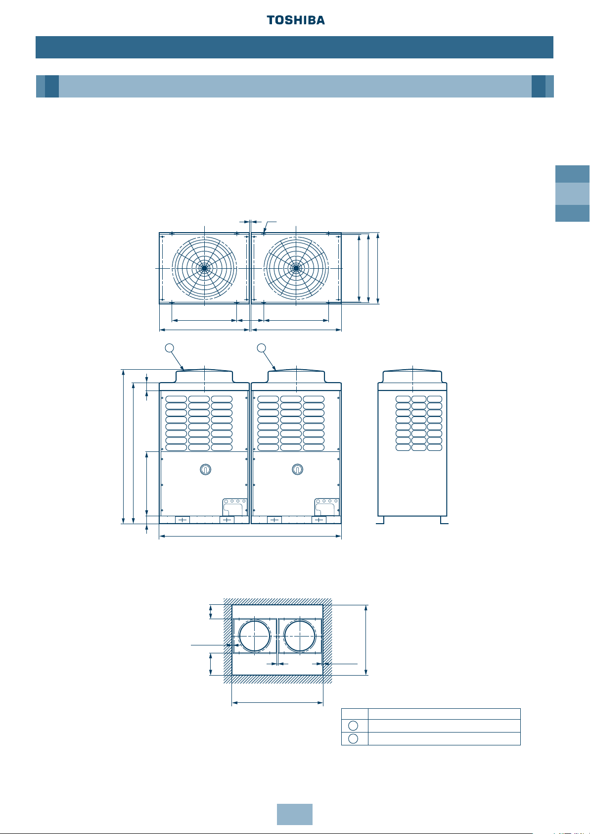
Installation
Dimensional Drawings
Two Units Connected
Model Name:
MM-A0384HT, MM-A0440HT, MM-A0504HT, MM-A0560HT
Outdoor Unit
2000
700
990 990
700
750
790
1700
1560
700
90
88
1 2
8-15 x 20 (Slot)
755 Fixing bolt pitch
Fixing bolt pitch
Fixing bolt pitch
(including fixed leg)
≥ 20
(Rear side)
≥ 300
≥ 10
≥ 500
(Front side)
≥ 20
≥ 2020
≥ 10
≥ 1550
No. Name
Outdoor Unit (Inverter type)
Outdoor Unit (Fixed-speed type)
1
2
Note: All dimensions in (mm)
Page 14
GB
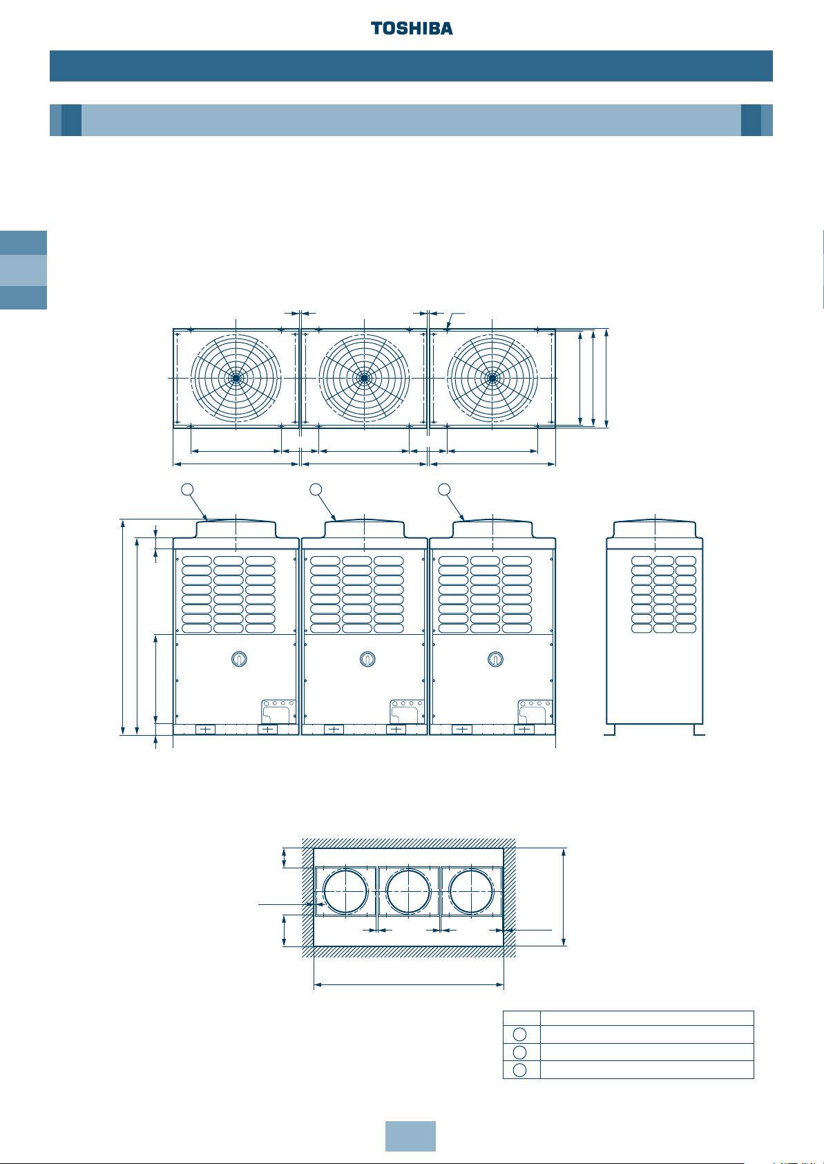
14
Dimensional Drawings
Three Units Connected
Model Name:
MM-A0608HT, MM-A0672HT, MM-A0728HT, MM-A0784HT, MM-A0840HT
Installation
Outdoor Unit
700
990 990 990
700 700
750
790
1700
1560
700
90
88
1
2
3
310
310
≥ 20
≥ 20
12-15 x 20 (Slot)
755 Fixing bolt pitch
(including fixed leg)
Fixing bolt pitch
Fixing bolt pitch
Fixing bolt pitch
(Rear side)
≥ 300
≥ 10
≥ 500
(Front side)
≥ 20
≥ 20
≥ 3030
≥ 10
≥ 1550
No. Name
Outdoor Unit (Inverter type)
Outdoor Unit (Fixed-speed type 1)
Outdoor Unit (Fixed-speed type 2)
1
2
3
Note: All dimensions in (mm)
Page 15
GB
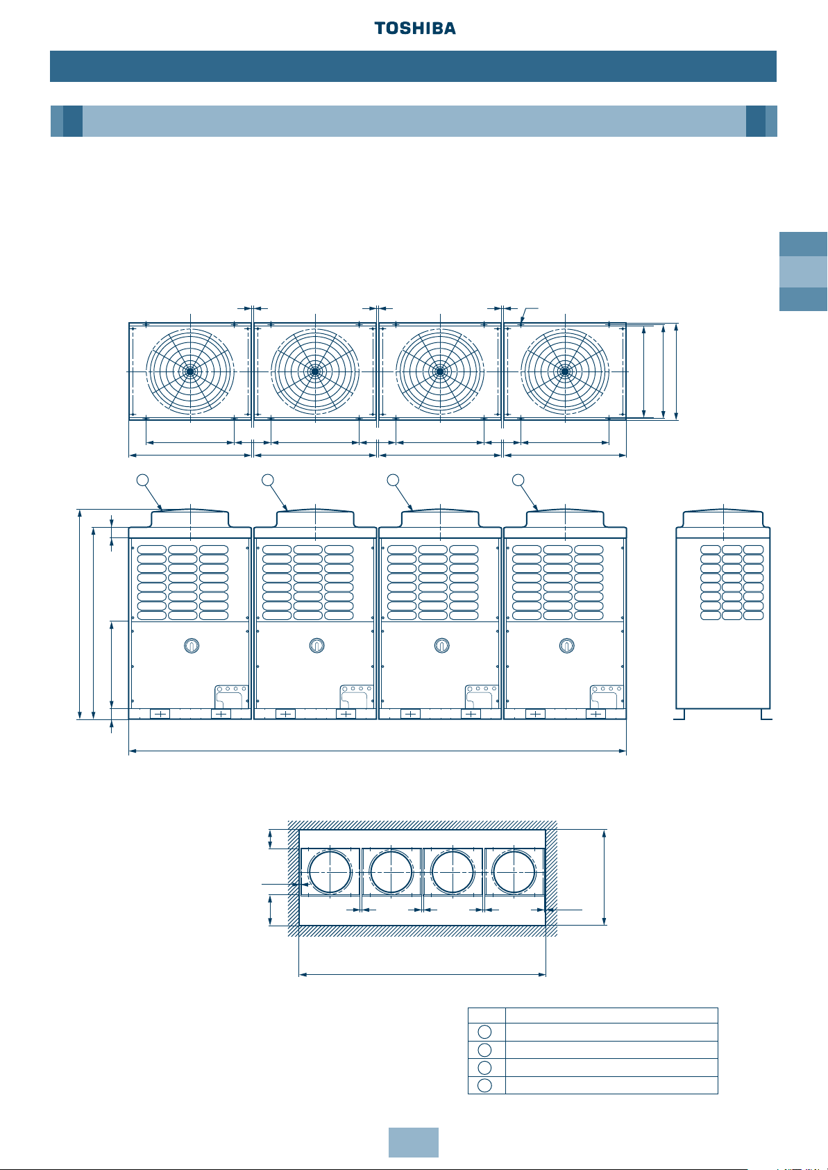
15
Dimensional Drawings
Four Units Connected
Model Name:
MM-A0896HT, MM-A0952HT, MM-A1008HT, MM-A1064HT, MM-A1120HT
Installation
Outdoor Unit
≥ 20
≥ 20 ≥ 20
16 - 15 x 20 (Slot)
755 Fixing bolt pitch
(including fixed leg)
(Rear side)
≥ 300
≥ 10
≥ 500
(Front side)
4020
1700
1560
700
90
88
700
990
700
990
700
990
700
750
790
1
2
3
4
990
310
310
310
≥ 20
≥ 20
≥ 20
≥ 4040
No. Name
Outdoor Unit (Inverter type)
Outdoor Unit (Fixed-speed type 1)
Outdoor Unit (Fixed-speed type 2)
Outdoor Unit (Fixed-speed type 3)
1
2
3
4
Fixing bolt pitch
Fixing bolt pitch Fixing bolt pitch Fixing bolt pitch
≥ 1550
≥ 10
Note: All dimensions in (mm)
Page 16
GB
16
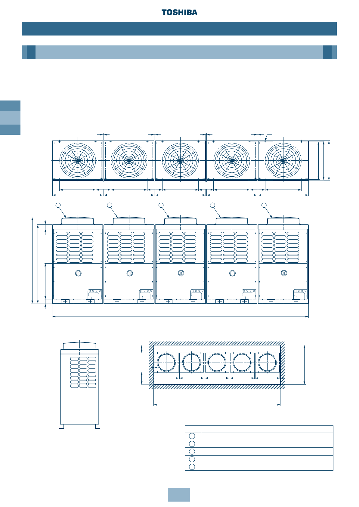
Dimensional Drawings
Five Units Connected
Model Name:
MM-A1176HT, MM-A1232HT, MM-A1288HT
Installation
Outdoor Unit
5030
1700
1560
700
90
88
700
990
700
990
700
990
700
1
2
3
4
990
700
700
790
5
990
310
310
310
310
≥ 20 ≥ 20 ≥ 20 ≥ 20
20 - 15 x 20 (Slot)
755 Fixing bolt pitch
(including fixed leg)
Fixing bolt pitch Fixing bolt pitch Fixing bolt pitch Fixing bolt pitch Fixing bolt pitch
(Rear side)
≥ 300
≥ 10
≥ 500
(Front side)
≥ 10
≥ 1550
≥ 20 ≥ 20 ≥ 20 ≥ 20
≥ 5050
No. Name
Outdoor Unit (Inverter type)
Outdoor Unit (Fixed-speed type 1)
Outdoor Unit (Fixed-speed type 2)
Outdoor Unit (Fixed-speed type 3)
Outdoor Unit (Fixed-speed type 4)
1
2
3
4
5
Note: All dimensions in (mm)
Page 17
GB
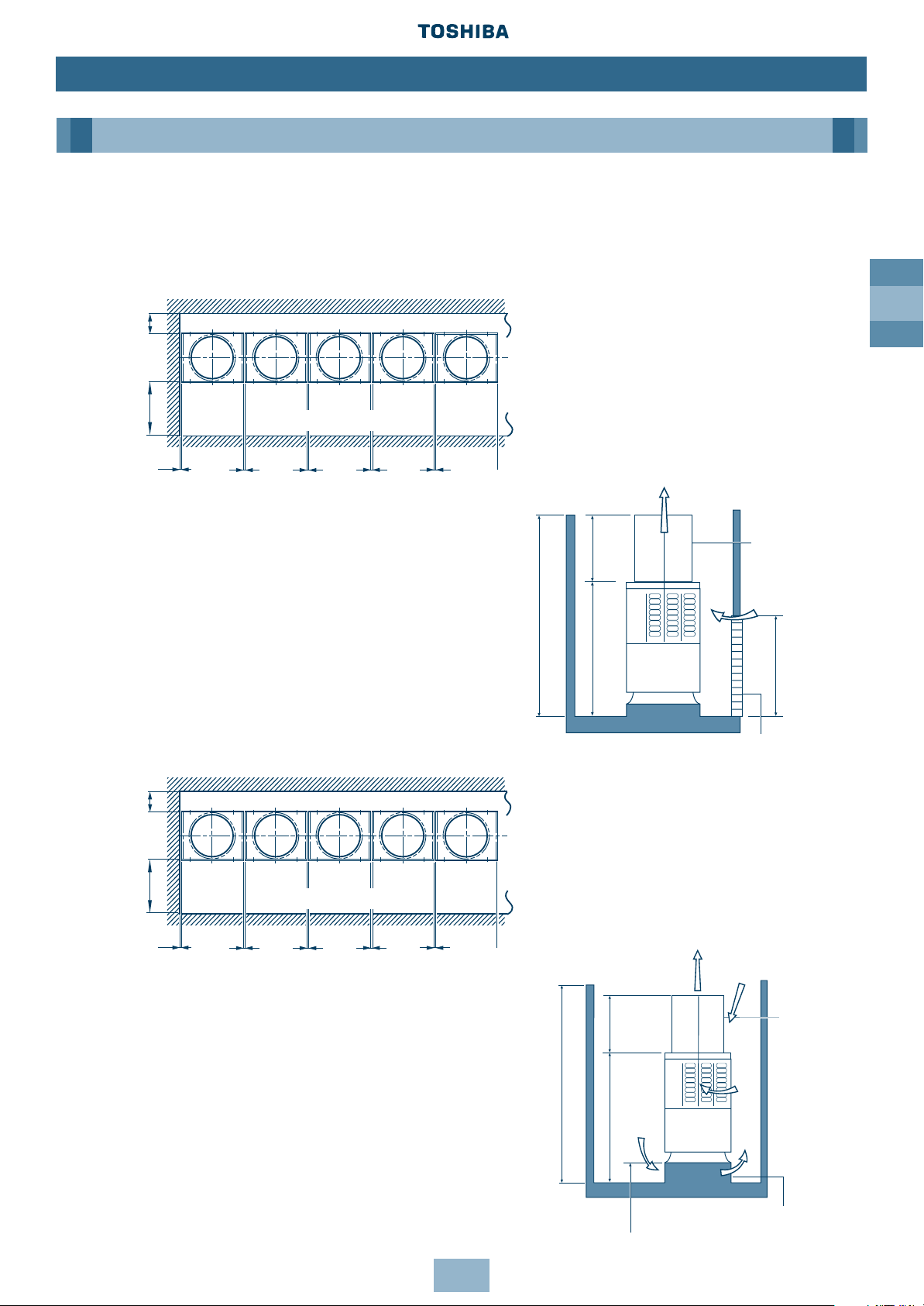
17
Multiple Installation on the Rooftop
When the Outer Wall is Higher than the Outdoor Unit
If a hole can be made in the wall:
1. Set an aperture ratio so that suction air volume
Vs from the hole becomes 1.5m/s or less.
2. Height of discharge duct: HD = H - h.
If a hole cannot be made:
1. Set a base with 500 to 1,000mm height.
2. Height of discharge duct: HD = H - h.
Installation
Outdoor Unit
≥ 300
≥ 600
≥ 20 ≥ 20 ≥ 20 ≥ 20≥ 10
(Front side)
Discharge duct
≥ 1000
Hole in wall
Vs
HD
h
H
Discharge duct
Base
500 – 1000
Vs
HD
H
≥ 300≥ 600
≥ 20 ≥ 20 ≥ 20 ≥ 20≥ 10
(Front side)
h
Note: All dimensions in (mm)
Page 18
GB
18
Installation
Outdoor Unit
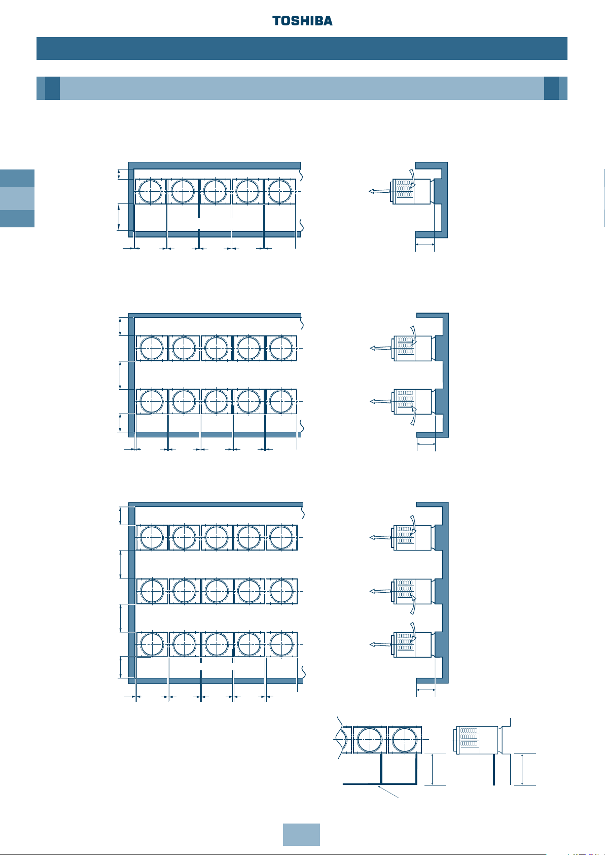
When the Outer Wall is Lower than the Outdoor Unit
1-line installation
2-parallel lines installation
3-parallel lines installation
*When refrigerant piping is routed from the front
of the unit, distance between Outdoor Unit and
Connecting piping must be 500mm or more.
≥ 300
≥ 500
≥ 20 ≥ 20 ≥ 20 ≥ 20≥ 10
(Front side)
≥ 600
*(≥ 1000)
≥ 300
≥ 300
≥ 20 ≥ 20 ≥ 20 ≥ 20
≤ 800
≥ 10
(Front side)
≥ 600
*(≥ 1000)
≥ 300
≥ 500 ≥ 600
≥ 20 ≥ 20 ≥ 20 ≥ 20≥ 10
(Front side)
(Front side)
≤ 800
≤ 800
≥ 500
≥ 500
Connecting Piping
Piping
Note: All dimensions in (mm)
Page 19
GB
19
Installation
Piping
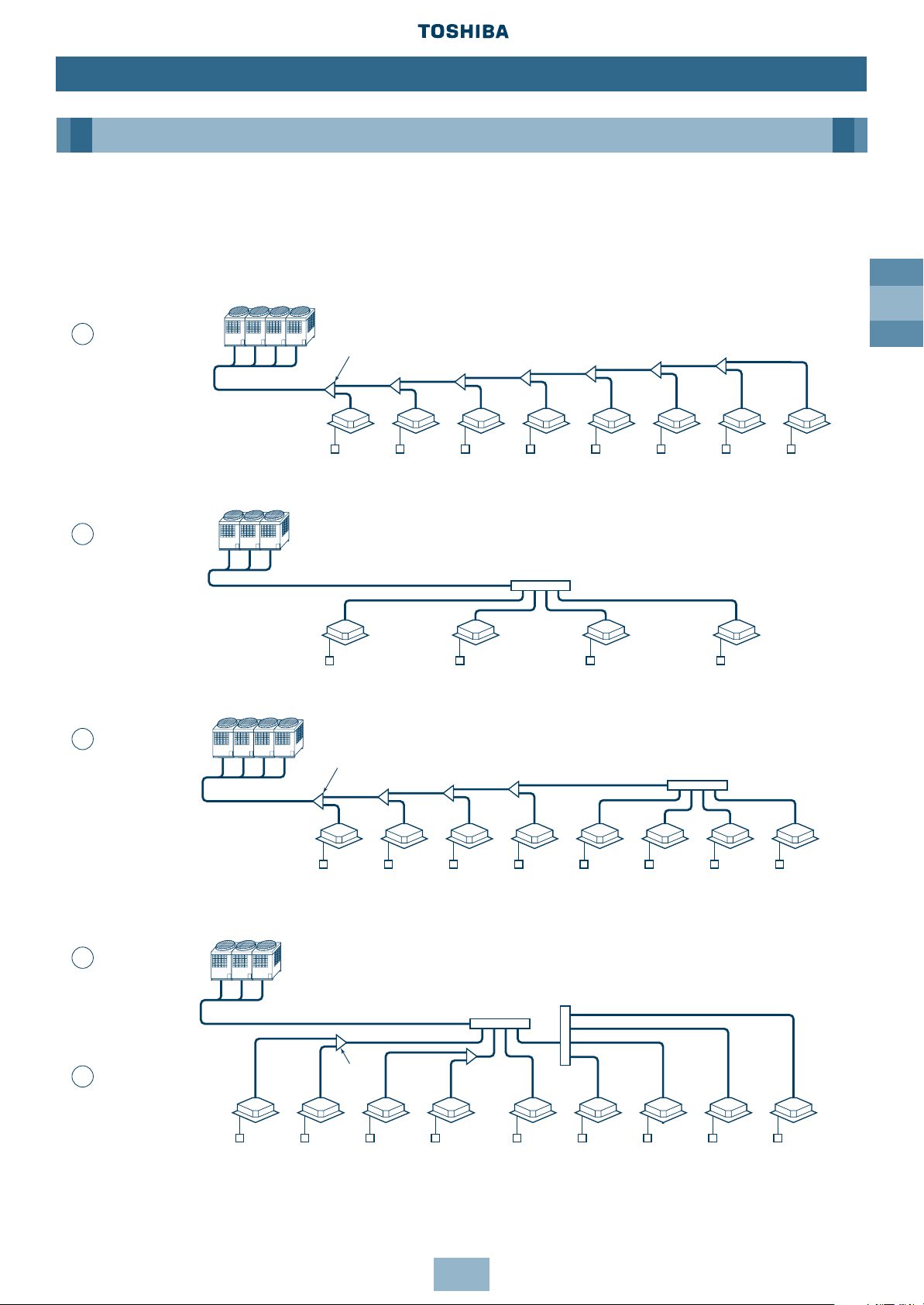
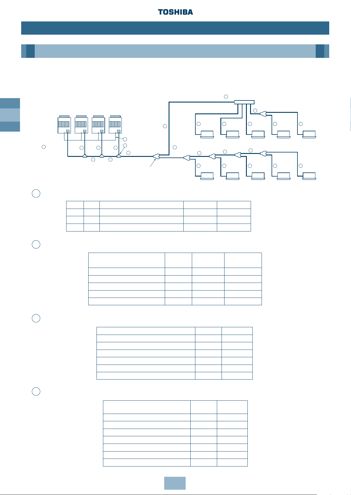
Free Branching System
The following five branching systems are available to increase the flexibility of refrigerant
piping design.
Outdoor units
Branching joint
Indoor
units
Line
branching
system
Remote
controller
Outdoor units
Branching
joint
Indoor
units
Line
branching
system after
header
branching
Header
branching
system after
header
branching
Remote
controller
Outdoor units
Branching joint
Indoor
units
Header
branching
system
after line
branching
Remote
controller
Outdoor units
Branching header
Branching header
Branching header
Indoor
units
Header
branching
system
Remote controller
1
2
3
4
5
Page 20
GB
20
Installation
Piping
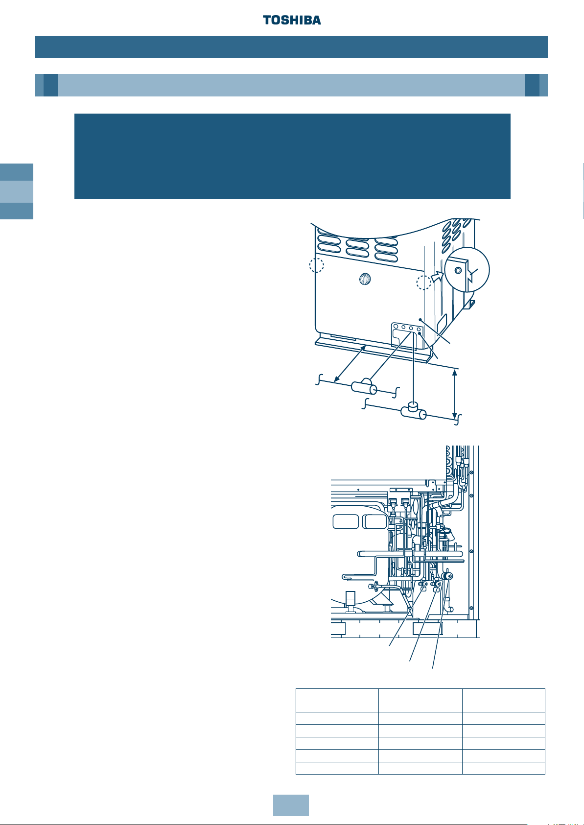
Connecting Refrigerant Pipes
1. To access the refrigerant piping
connections and electrical wiring
terminals, remove the 7xM5 securing
bolts in the front panel. To remove the
panel, lift it up and away from its hanging
tabs – See diagram.
2. The refrigerant pipes can be routed
forwards, downwards or sideways.
3. If the pipes are routed forwards, make
sure they exit through the Piping/Wiring
Panel – (remove knock out section) and
allow at least 500mm between the
Outdoor Unit and the main pipe
connecting it to the Indoor Unit. This is for
servicing access. (Replacing the
compressor, for example, requires a space
of at least 500mm.)
4. If the pipes are routed downwards,
remove the knockout section in the
baseplate of the Outdoor Unit. This will
enable access. They can then be
connected to the left or right, or the rear
side. (Leading pipe of the balancing
should be within 4m.)
Notes:
1. When brazing, use nitrogen. This prevents
internal oxidisation of the pipes.
2. Always use clean new pipe, and ensure it
is not contaminated by water or dust.
3. Always use a double spanner on the flare
nut – and tighten to the specified torque:
(see table).
Connecting pipe Tightening Re-tightening
outer dia. (mm) torque (Nm) torque (Nm)
Ø6.4 11.8 (1.2kgf m) 13.7 (1.4kgf m)
Ø9.5 24.5 (2.5kgf m) 29.4 (3.0kgf m)
Ø12.7 49.0 (5.0kgf m) 53.9 (5.5kgf m)
Ø15.9 78.4 (8.0kgf m) 98.0 (10.0kgf m)
Ø19.0 98.0 (10.0kgf m) 117.7 (12.0kgf m)
WARNING!
During installation – if the refrigerant gas leaks, ventilate the room.
After installation – check for gas leakages.
If refrigerant gas comes into contact with fire – noxious gas may result!
Front panel
Piping/Wiring Panel
Within 4m
Pipes routed downwards
Pipes routed
forward
≥ 500
Ta b
Valve at balance side (oil)
Valve at liquid side
Valve at gas side
Note: All dimensions in (mm)
Page 21
GB
21
Installation
Piping
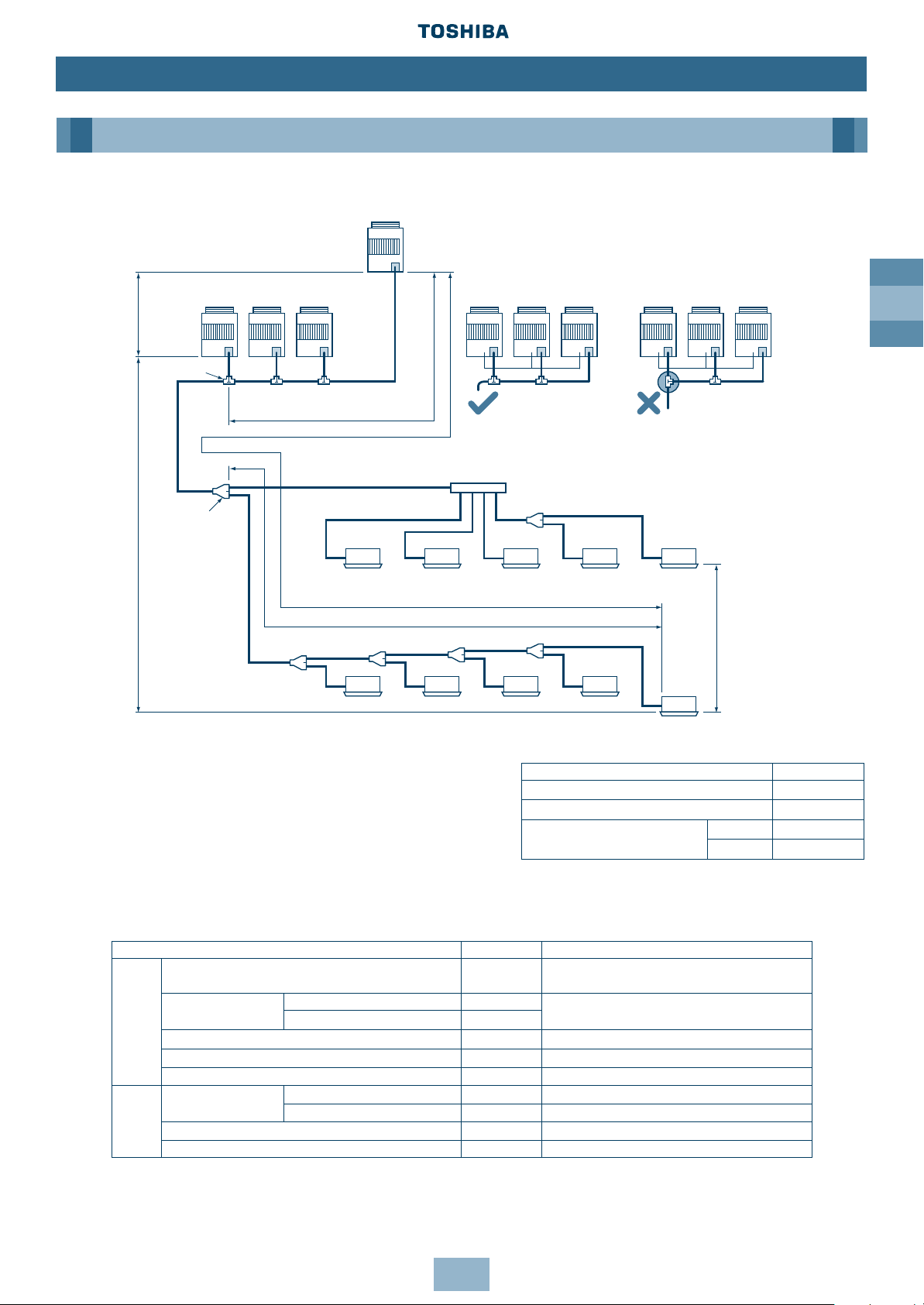
Permissible Length/Height Separation of Refrigerant Piping
La
LA LB
Lb Lc
L1
L2
L7
bc dea
ghi jf
L4
L5
L6
L3
Ld
(a)
(d)
(b) (c)
Fixed-speed
Unit n
Valve for
additional Units
Valve for
additional Units
Note: In <Ex.2>, a large amount of refrigerant and oil may
return to the Inverter Unit. Therefore, set the
T-shape joint so that oil does not enter directly.
Branching header
Branching piping
Connecting piping of Indoor Unit
Indoor Unit
Length corresponded to farthest piping L≤ 125m
Length corresponded to farthest piping after 1st branching L≤ 50m
Height difference
between Indoor
Units
H2≤ 30m
Indoor Unit
1st branching
section
Main
piping
Main connecting piping between Outdoor Units
Length corresponded to farthest piping
between Outdoor Units LO≤ 20m
Connecting
piping of
Outdoor
Unit
Fixedspeed
Unit 2
Fixedspeed
Unit 1
Inverter
Unit
Fixed-
speed
Unit 2
Fixedspeed
Unit 1
Inverter
Unit
Fixedspeed
Unit 2
Fixedspeed
Unit 1
Inverter
Unit
Outdoor
Unit
Height
difference
between
Outdoor
Units
H3≤ 4m
Height
difference
between
Outdoor
Units
H1≤ 50m
T-shape branching
joint
Y-joint
System Restrictions
Notes: Combination of Outdoor Units: Inverter Unit +
Fixed-speed Unit (0 to 4 units).
Combination of Fixed-speed Units without
Inverter Unit is not permissible.
The Inverter Unit is the master Outdoor Unit
and is directly connected to the indoor
distribution pipe.
Install the Outdoor Units in order of capacity.
(Inverter Unit≥ Fixed-speed Unit 1> Fixed-speed Unit 2>Fixed-speed Unit n).
Max. No. of combined outdoor units 5 units
Max. capacity of combined outdoor units 128.8kW/46HP
Max. No. of connected indoor units 40 units
Max. capacity of combined H2≤ 15 135%
indoor units H2>15 105%
Allowable value Piping section
Total extension of pipe (Liquid pipe, real length) 250m
LA + LB + La + Lb + Lc + Ld + L1 + L2 + L3 + L4+
L5 + L6 + L7 + a + b + c + d + e + f + g + h + i + j
Farthest piping length L (*)
Real length 100m
LA + LB + Ld + L1 + L3 + L4 + L5 + L6 + j
Piping Equivalent length 125m
length Equivalent length of farthest piping from 1st branching Li (*) 50m L3 + L4 + L5 + L6 + j
Equivalent length of farthest piping between outdoor units LO (*) 20m LA + LB + Ld, LA + Lb, LA + LB + Lc
Max. equivalent length of outdoor unit connecting piping 10m Ld, La, Lb, Lc
Height between indoor
Upper outdoor unit 50m ——
Height
and outdoor units H1
Lower outdoor unit 30m ——
difference Height between indoor units H2 30m ——
Height between outdoor units H3 4m ——
*(d) is Outdoor Unit farthest from branching and (j) is Indoor Unit farthest from 1st branching.
<Ex. 1> <Ex. 2>
Page 22
GB
22
Installation
Piping
Selection of Refrigerant Piping and Charge Requirement
3
1
1 1 1
22
4
5 5 5
4
4
4
4
5 5
5 5 5 5 5
2
6
6
6
Fixedspeed
Unit n
Fixedspeed
Unit 2
Fixedspeed
Unit 1
Inverter
Unit
Branching piping
Header Branching Pipe
Outdoor Unit
Outdoor
Unit
connecting
piping
Main connecting
piping between
Outdoor Units
Main piping
T-shape branching joint
Balance pipe
Y-shape branching
joint
Indoor Unit
connecting
piping
1st branching
section
Indoor Unit
Indoor Unit
Indoor Unit connecting pipe
kW HP Model name Gas side Liquid side
16.0 6 MM-A0160HX Ø22.2 Ø9.5
22.4 8 MM-A0224HT, MM-A0224HX Ø22.2 Ø12.7
28.0 10 MM-A0280HT, MM-A0280HX Ø28.6 Ø12.7
Total capacity code of all outdoor units Gas side Liquid side
Below 10 Ø22.2 Ø12.7
10 to Below 14 Ø28.6 Ø12.7
14 to Below 20 Ø34.9 Ø15.9
20 to Below 26 Ø41.3 Ø19.0
26 to Below 32 Ø41.3 Ø22.2
32 or more Ø54.1 Ø22.2
Total capacity code of indoor units
Gas side Liquid side
downstream (*1)
Below 4.0 Ø15.9 Ø9.5
4.0 to Below 6.4 Ø19.0 Ø9.5
6.4 to Below 13.2 Ø22.2 Ø12.7
13.2 to Below 19.2 Ø34.9 Ø15.9
19.2 to Below 25.2 Ø41.3 Ø19.0
25.2 to Below 31.2 Ø41.3 Ø19.0
31.2 or more Ø54.1 Ø22.2
Total capacity code of outdoor
Gas side Liquid side Balance pipe
units
Below 16 Ø28.6 Ø15.9 Ø9.5
16 to Below 20 Ø34.9 Ø15.9 Ø9.5
20 to Below 26 Ø41.3 Ø19.0 Ø9.5
26 to Below 32 Ø41.3 Ø22.2 Ø9.5
32 or more Ø54.1 Ø22.2 Ø9.5
Pipe Size of Outdoor Unit
Connecting Pipe Size Between Outdoor Units
Size of Main Pipe
Size Between Branching Sections
1
2
3
4
Note: All dimensions in (mm)
Page 23
GB
23
Installation
Piping
Unit Gas side
(*4)
Liquid side
028 type to 056 type Ø12.7 Ø 6.4
080 type Ø15.9 Ø 9.5
112 type to 140 type Ø19.0 Ø 9.5
i.e. MM-SB028 = Gas Ø12.7, Liquid Ø6.4
Liquid pipe size Additional refrigerant amount for liquid pipe 1m (kg)
Ø6.4 0.030
Ø9.5 0.065
Ø12.7 0.115
Ø15.9 0.190
Ø19.0 0.290
Ø22.2 0.420
Piping of Indoor Unit
Additional Refrigerant Amount
(*1) Code is determined according to the capacity code of the Indoor Units connected. For
details, refer to the Introduction section in this manual.
(*2) If the total capacity code value of Indoor Units exceeds that of Outdoor Units, apply the
capacity code of Outdoor Units.
(*3) When using a branch header, Indoor Units with a maximum of 6.0 capacity code in total
can be connected to each branch.
(*4) If the length of the gas pipe exceeds 30m from the 1st branching to an Indoor Unit,
increase the Gas pipe section by 1 size, i.e. MM-U140 = Gas Ø22.2, Liquid Ø9.5.
5
6
7
Note: All dimensions in (mm)
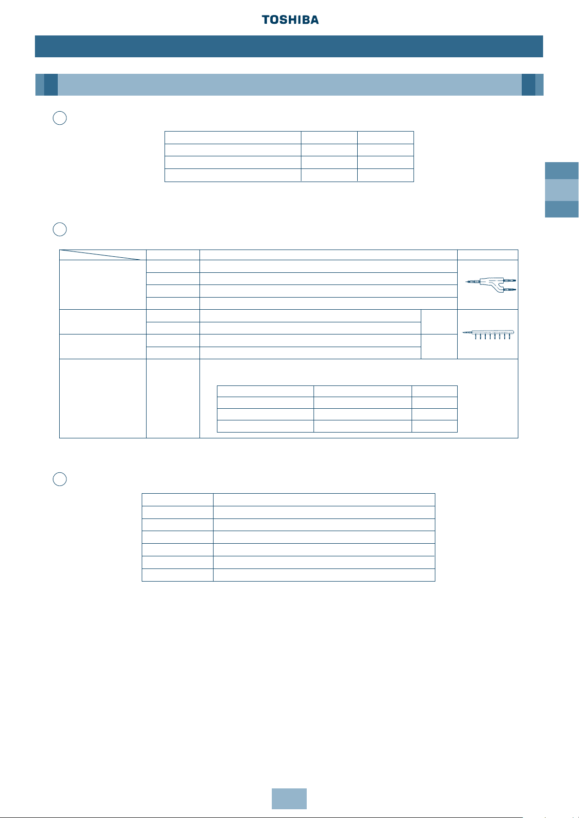
Model name Usage Appearance
RBM-Y018 Indoor unit capacity code (*1): Total below 6.4
Y-shape RBM-Y037 Indoor unit capacity code (*1): Total 6.4 or more and below 13.2 (*2)
branching joint RBM-Y071 Indoor unit capacity code (*1): Total 13.2 or more and below 25.2 (*2)
RBM-Y129 Indoor unit capacity code (*1): Total 25.2 or more (*2)
4-branching header (*3)
RBM-H4037 Indoor unit capacity code (*1): Total below 13.2
Max. 4
RBM-H4071 Indoor unit capacity code (*1): Total 13.2 or more and below 25.2
branches
8-branching header (*3) RBM-H8037 Indoor unit capacity code (*1): Total below 13.2
Max. 8
RBM-H8071 Indoor unit capacity code (*1): Total 13.2 or more and below 25.2
branches
1 set of 3 types of T-shape joint pipes as described below:
The required quantity is arranged and they are combined at the site.
T-shape branching joint
(For connection of RBM-T129
outdoor unit)
Connecting pipe Corresponding dia. (mm) Qty
Balancing pipe Ø9.52 1
Piping at liquid side Ø12.7 to Ø22.2 1
Piping at gas side Ø22.2 to Ø54.1 1
Branching joints/headers
Page 24
GB
24
Installation
Piping
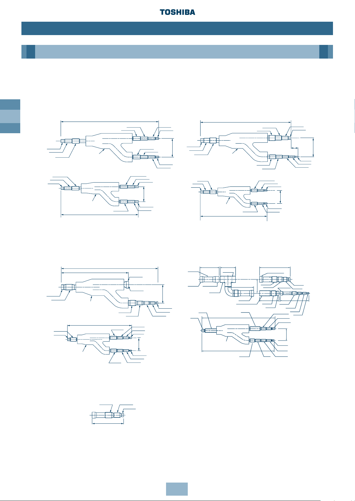
Branch Headers/Branch Joints (Accessories)
Note:
This additional connecting pipe is used if the
gas pipe size is Ø41.3 or less. When brazing,
the minimum insertion margin is 15mm.
Y-shape Branch Joint
Note: All dimensions in (mm)
[Gas side]
[Liquid side]
[Liquid side]
[Gas side]
Heat insulator
Heat insulator
RBM-Y018
RBM-Y037
Heat insulator
Heat insulator
Ø9.5
Ø9.5
Ø6.4
Ø6.4
Ø9.5
Ø19.0
Ø19.0
Ø28.6
571
Ø22.2
Ø22.2
Ø28.6
Ø9.5
Ø12.7
Ø15.9
Ø15.9
Ø12.7
Ø12.7
Ø12.7
Ø12.7
Ø9.5
Ø9.5
Ø9.5
Ø6.4
Ø6.4
420
Ø15.9
Ø19.0
Ø19.0
Ø15.9
Ø19.0
Ø9.5
Ø22.2
528
Ø15.9
Ø15.9
Ø12.7
Ø9.5
Ø22.2
Ø31.8
100
80
Ø12.7
Ø12.7
Ø12.7
44
Ø15.9
80
120
420
Heat insulator
Heat insulator
[Gas side]
[Gas side]
[Liquid side]
[Liquid side]
RBM-Y071
RBM-Y129
Ø12.7
Ø9.5
Ø6.4
85
Ø15.9
Ø19.0
518
Heat insulator
523
Ø19.0
Ø22.2 Ø22.2
Ø41.3
Ø41.3
Ø34.9
Ø34.9
Ø41.3
Ø22.2
Ø19.0
Ø15.9
Ø19.0
Ø19.0
Ø6.4
Ø9.5
Ø15.9
Ø15.9
Ø15.9
122.5
85
Ø12.7
Ø12.7
Ø12.7
Ø9.5
A
444
423
638
Ø54.1
(outer dia.)
Ø54.1
Ø54.1
Ø41.3
Ø54.1
212
Ø41.3
(outer dia.)
Ø19.0
Ø19.0
Ø22.2
237
Ø34.9
160
Ø41.3
Ø15.9
Ø15.9
Ø12.7
Ø12.7
Ø34.9
Ø22.2
Ø54.1
(outer dia.)
253.5
126160
Ø34.9
(outer dia.)
Ø41.3
Ø41.3
Ø19.0
194
Ø34.9
Ø22.2
Page 25
GB
25
Installation
Piping
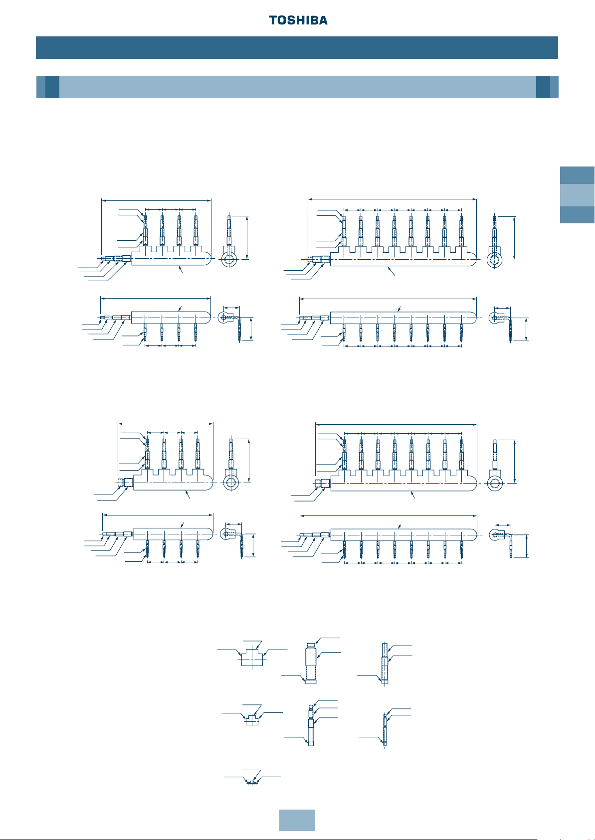
Branch Header
Note: Pipe dia. shown indicates dia. of pipe to be connected.
T-shape Branch Joint
Note: All dimensions in (mm)
RBM-H8037
[Gas side]
[Liquid side]
Heat insulator
RBM-H4037
[Gas side]
[Liquid side]
Heat insulator
Heat insulator
Heat insulator
515
Ø15.9
Ø12.7
Ø12.7
Ø15.9
Ø15.9
Ø19.0
Ø19.0
80 80 80
80 80 80
204
109
522
75
Ø19.0
Ø9.5
Ø6.4
Ø9.5
Ø9.5
Ø22.2
Ø28.6
Ø9.5
Ø9.5
Ø9.5
Ø6.4
80 80 80 80 80 80 80
80808080808080
75
109
204
842
795
Ø12.7
Ø12.7
Ø19.0
Ø19.0
Ø19.0
Ø2.22
Ø28.6
Ø15.9
Ø15.9
RBM-H4071
RBM-H8071
[Gas side]
[Gas side]
[Liquid side]
[Liquid side]
Heat insulator
Heat insulator
Heat insulator
Heat insulator
80 80 80
8080 80
209
109
449
522
Ø9.5
Ø9.5
Ø9.5
Ø6.4
Ø19.0
Ø19.0
Ø34.9
Ø41.3
Ø15.9
Ø15.9
Ø12.7
Ø12.7
75
Ø9.5
Ø9.5
Ø34.9
Ø9.5
Ø6.4 80 8080808080 80
80 80 80 80 80 80 80
75
209
109
842
769
Ø12.7
Ø12.7
Ø41.3
Ø15.9
Ø19.0
Ø19.0
Ø15.9
RBM-T129
[Gas side]
[Liquid side]
[Balance side]
Outside
diameter
Outside
diameter
2 pieces
included
3 pieces
included
3 pieces
included
2 pieces
included
Outside
diameter
Ø54.1
Ø54.1
Ø54.1
Ø54.1
Ø22.2
Ø22.2
Ø22.2
Ø22.2
Ø9.52
Ø9.52
Ø9.52
Ø22.2
Ø19.0
Ø34.9
Ø34.9
Ø41.3
Ø28.6
Ø22.2
Ø12.7
Ø9.53
Ø15.9
Ø15.9
Page 26
GB
26
Piping
Installation
Connecting the Branching Kit
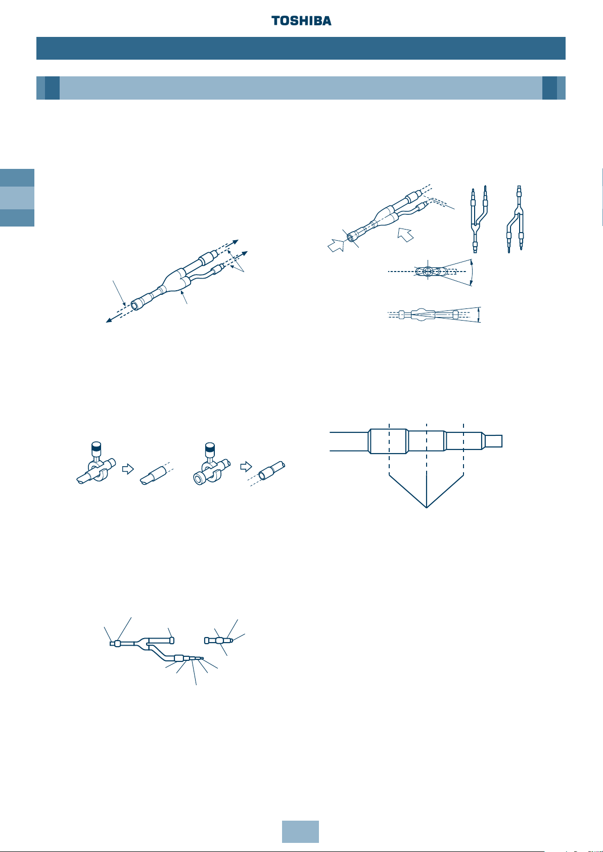
Y-shape Branching Joint
Y-shape Branching Joint for gas and liquid
distribution
When the selected pipe size differs from the
size of the y-shape branching joint pipe, cut
the centre of the connecting section with a
pipe cutter, as shown below.
• Use the attached auxiliary pipe to adjust
the pipe dia. of the Y-shape branching
joint at gas or liquid side (RBM-Y071,
RBM-Y129). Cut the branched pipe and
auxiliary pipe to the specified size, and
then braze.
Piping at site
Piping at site
To Outdoor Unit
Y-shape branching joint for
gas side/liquid distribution
To other Branching Pipe
or Indoor Unit
Inlet
Outlet (1)
Outlet (2)
Ø34.9
Ø41.3
Ø41.3
Ø34.9
Ø22.2
Ø19.0
Auxiliary pipe
at gas side
Ø12.7
Ø15.9
Ø19.0
Ø34.9
Ø22.2
Y-shape Joint for gas and liquid distribution
• Install Y-shape branching joint so that it
branches horizontally or vertically.
• Be sure to fit the insulation to the Y-shape
branching joint supplied in the kit.
• Cutting position
Cut the pipe at the centre of each
connecting section, and remove burr.
A
(Horizontal line)
(Horizontal line)
(A view)
(B view)
Within ± 30°
Within ± 30°
B
or
Cut at the centre
Note: All dimensions in (mm)
Page 27
GB
27
Installation
Piping
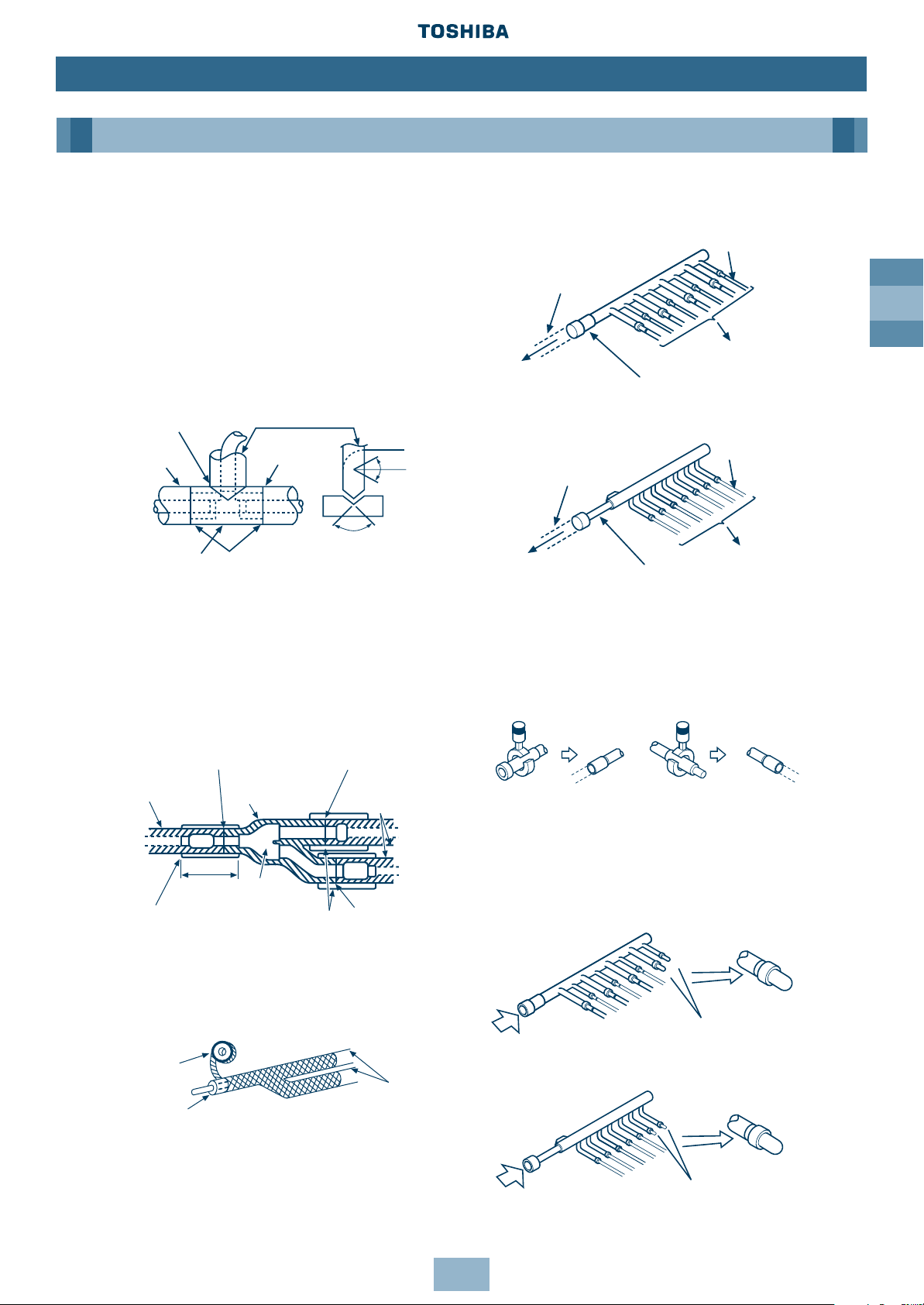
Branching Header
When the selected pipe size prepared at
site differs from the size of the branching
header pipe, cut the centre of the
connecting section with a pipe cutter
as shown.
If the number of Indoor Units to be
connected is less than the number of
connections on the Branching Header, braze
a pipe cap to the unused connectors.
Heat Insulating the Branching Pipes
Ensure the pipe insulation covers the piping
up to the brazed accessory joints, as this will
eliminate ingress of water – tape the pipe
insulation to a thickness of 10mm or more,
as shown.
RBM-Y129 (Gas side) (Prepared at site)
RBM-Y071 (Gas side, Liquid side),
RBM-Y129 (Liquid side)
Use insulator with a heat resistance of 120° C
or over for gas pipes. To insulate the
Branching Pipes, use a T-Shaped Joint cover
with a thickness of 10mm or over – or a
machined insulation portion, as shown.
• After the heat insulating, tape to seal.
Seal the joint with
urethane foaming
agent, etc.
Pipe heat
insulator
Cut by
approx.
60°
Cut by
approx. 90°
Seal with
vinyl tape
Heat insulating
pipe for piping
Heat insulating
pipe for piping
Bring them face
to face
Pipe heat insulator
prepared at site
Heat insulator (prepared at site),
10mm or over
150
Branching Pipe
Heat insulator
included accessory
Pipe heat
insulator
prepared at site
Place them edge to edge
Place them
edge to edge
Place them edge to edge
Taping
(prepared
at site)
Heat insulator
(prepared at site)
Heat insulator
(prepared
at site)
Prepared at site
Prepared at site
Prepared at site
To Indoor Unit
Gas branching header
Liquid branching header
To Indoor Unit
Prepared at site
To Outdoor
Unit
To Outdoor
Unit
Liquid side
Gas side
Gas side
Liquid side
B
B
Pipe cap
Pipe cap
Inlet
Inlet
Page 28
GB
28
Installation
Piping
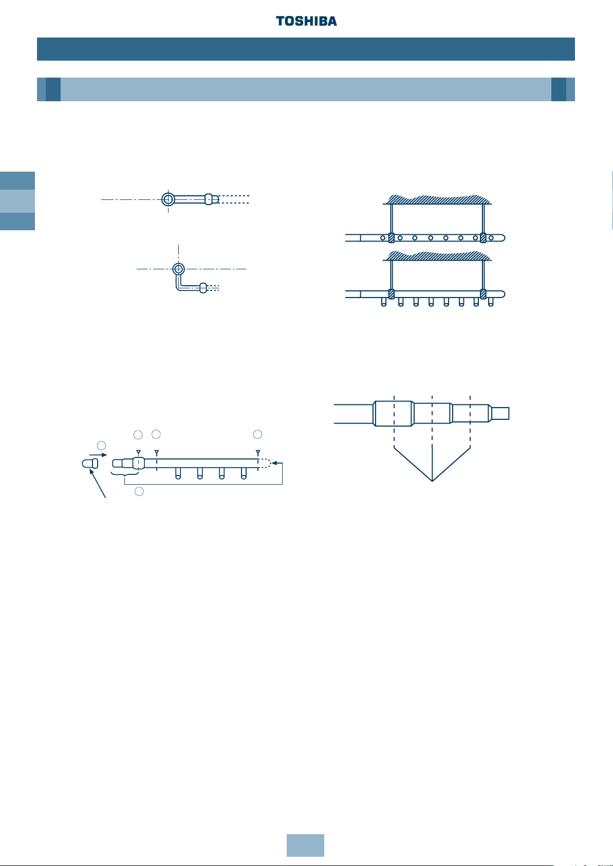
• Install the branching header so that it
branches horizontally. DO NOT install
vertically.
• Be sure to insulate the branching header
with the insulation provided.
• When routing the branching header at
the liquid side from the opposite side,
cut both ends and use a pipe cap (not
supplied), as shown.
• Support of branching header
Set a hanging metal support (prepared at
site) for the branching header, after fitting
heat insulation.
• Cutting position
Cut the centre of each connecting section,
and remove burr.
Use a mini-cutter to cut branching headers
up to Ø22.2.
(Horizontal line)
(Horizontal line)
Gas side
Liquid side
(B view)
Gas side
(B view)
Liquid side
To B
B
Cut
A
Cut
C
Cut
To C
Pipe cap
Cut at the centre
Notes:
1. Make sure there’s a straight run of pipe at least 300mm long at the inlet side of
Y-shaped Branching Joints and Branching Headers.
2. Install Y-shaped Branching Joint so they branch horizontally or vertically. In horizontal
installations, set within ± 30°.
3. Install Branching Headers so they branch horizontally.
4. Do not use T-shaped Branching Joints for Branching Sections.
5. When using Y-Branches or Header Branches to prevent incorrect piping, attach a line number
or name to each pipe.
Note: All dimensions in (mm)
Page 29
GB
29
Installation
Piping
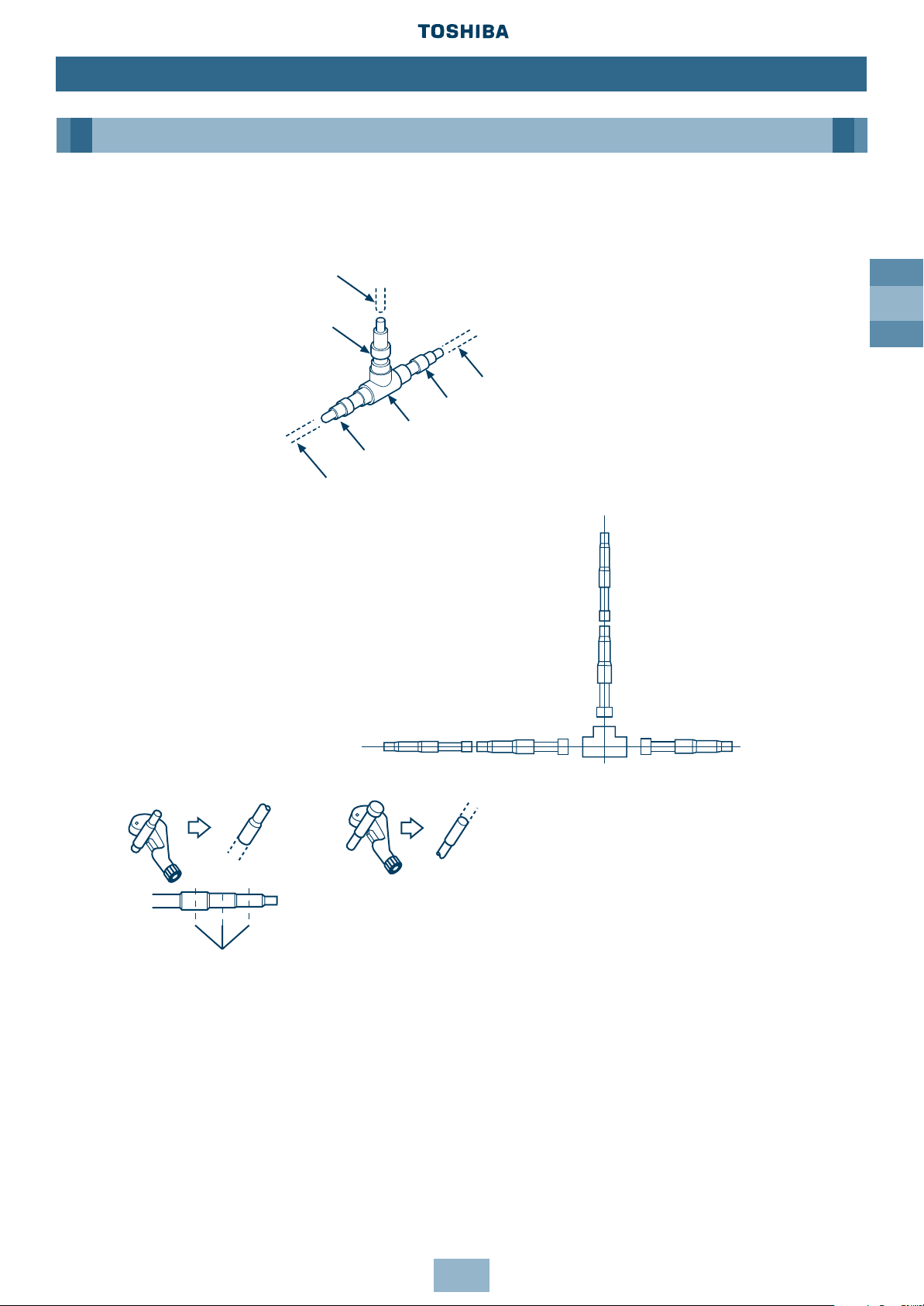
T-shape Branching Joint – to Connect Outdoor Units
Branching Pipes at Gas Side/Liquid Side
Pipe prepared at site
Pipe arranged at site
Pipe arranged at site
Connecting pipe at gas/liquid side
Connecting pipe at gas/liquid side
Branching Pipe at gas/liquid side
To other Branching
Pipe or Outdoor Unit
To other Branching
Pipe or Branching
Section of main pipe
To Outdoor Unit
Connecting pipe at
gas/liquid side
To Outdoor Unit
To other
Branching Pipe
or Outdoor Unit
To other Branching
Pipe or Branching
Section of main pipe
Cut the centre
• Use the included connecting pipes for
gas/liquid sides to match to the
appropriate pipe size. (The diagram shows
a connecting example.)
• Cutting position of connecting pipe
When the selected pipe size prepared
at site differs from the size of the
Branching Pipe, cut the centre of the
connecting section with a pipe cutter.
Page 30
GB
30
Installation
Piping
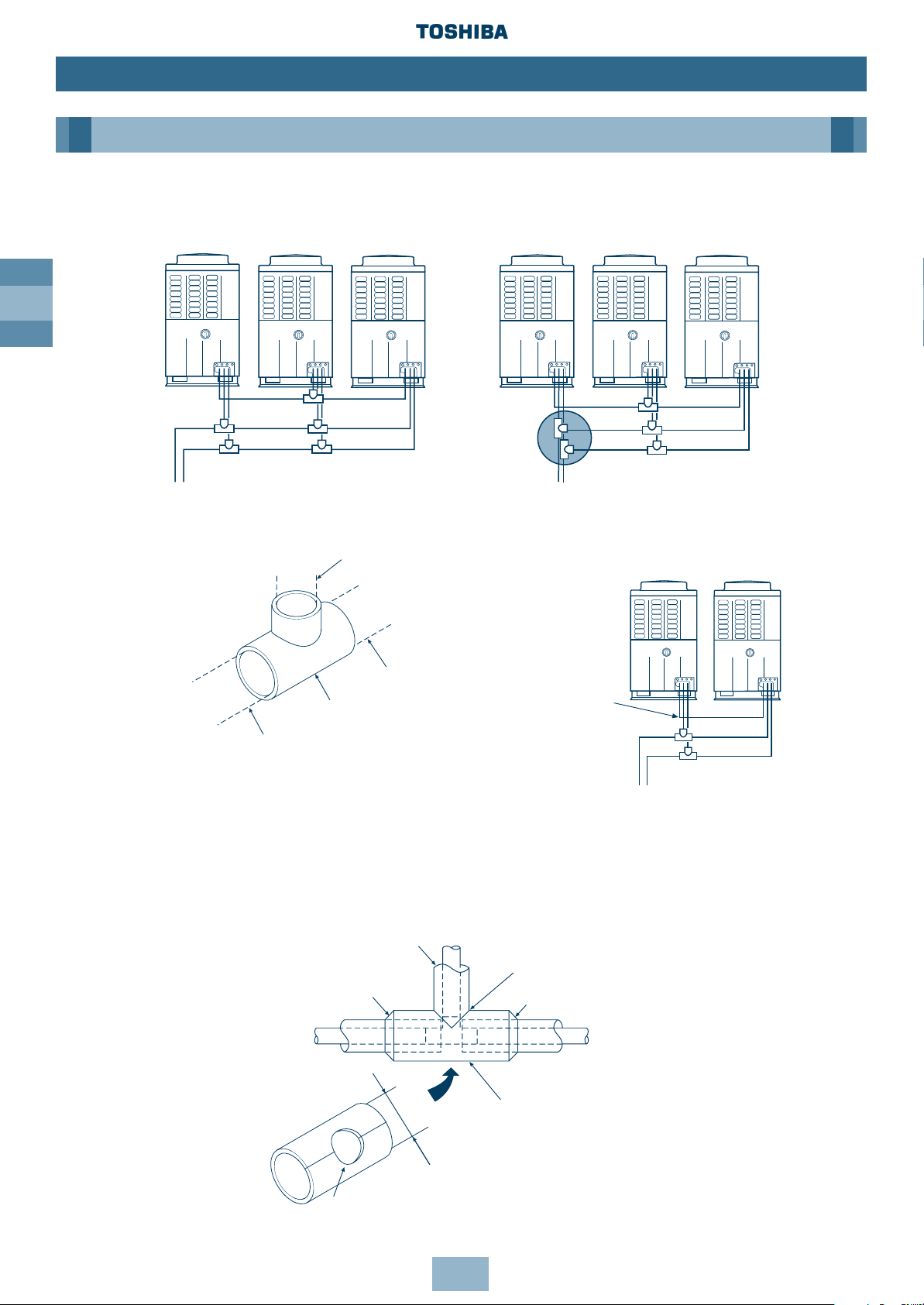
Installation of Gas/Liquid Branching Pipes
When
combining two
units, connect
directly.
Balancing Branch Pipes (Oil)
Heat Insulation
Insulate liquid side, gas side and Balancing Pipes separately.
Use insulator with a resistance of 120°C + for gas pipes.
To insulate the Branching Pipes, use a T-Shaped Joint cover with a thickness of 10mm or over
– or the machined one included. (Insulation for branching is not included.)
To prevent condensation or dripping – seal the Branching Pipe securely, with no gaps.
Inverter
Outdoor Unit
Fixed-speed
Outdoor Unit
Inverter
Outdoor Unit
Fixed-speed
Outdoor Unit
INCORRECT
ROUTING
To Outdoor
Unit
Branching Pipe for
Balancing Pipe (included)
Pipe prepared at site
Pipe prepared
at site
Pipe prepared
at site
To other
Branching Pipe
or Outdoor Unit
To other
Branching Pipe
or Outdoor Unit
Inverter
Outdoor Unit
Connect
Balancing
Pipe directly
Fixed-speed
Outdoor Unit
Seal with vinyl tape
Heat insulator
External dia. of
Branching Pipe
Seal the joint with urethane
foaming agent, etc.
Heat insulating pipe for piping
Heat insulating pipe for piping
Drill a hole with dia. larger than external
dia. of heat insulating pipe for piping
✖
✔
Page 31

GB
31
Installation
Piping
Airtight Test
Carry out an airtight test after the refrigerant piping is complete. For an airtight test, connect a
nitrogen gas bottle as shown, and apply pressure.
• Be sure to carry out the test from the service ports of the packed valves at both the gas side
and balance side.
• Complete the airtight test on the service ports at liquid, gas and balance sides of the Inverter
Outdoor Unit ONLY.
• Keep all of the valves at gas, liquid and balance sides fully closed. Nitrogen may enter the
cycle of the Outdoor Unit. Therefore, re-tighten the valve rod before applying pressure. (For
all valves at gas, liquid and balance sides.)
• For each refrigerant line, apply pressure gradually at gas, liquid and balance sides.
Be sure to apply pressure at gas, liquid and balance sides.
Never use oxygen, or a flammable noxious gas.
To detect a large leakage
STEP 1: 0.3MPa (3.0kg/cm
2
G) Apply pressure for 3 minutes or more
STEP 2: 1.5MPa (15kg/cm2G) Apply pressure for 3 minutes or more
To detect a fine leakage
STEP 3: 3.0MPa (30kg/cm2G) Apply pressure for 24 hours
• Check for a reduction in pressure.
If there is no reduction in pressure this is acceptable.
If there is a reduction in pressure check for leakage.
(Note: If there is a difference of ambient temp. between when the pressure was applied and
24 hours later, then pressure could change by approx. 0.01MPa (0.1kg/cm2G) – so correct the
pressure change.)
Detailed drawing of packed valve
To gauge manifold
Service port
at liquid side
Packed valve
at liquid side
Service port at
balance side
Packed valve at
balance side
Piping at site
Service port
at gas side
Packed valve
at gas side
Piping
at site
Piping at site
To main
unit
To main
unit
To main
unit
Connected to Indoor Unit
Connected to other fixed-speed Outdoor Unit
Packed valve fully
closed (liquid side)
Packed valve fully
closed (balance side)
Inverter Outdoor Unit
Service port
Service port
Gauge
manifold
Nitrogen
gas
Regulator
Ø6.4
Copper
pipe
Ø6.4
Copper
pipe
Packed valve fully
closed (Gas side)
Flare
connection
Flare
connection
Brazing
Lowpressure
gauge
Highpressure
gauge
Main pipe
Note: All dimensions in (mm)
Page 32

GB
32
Installation
Piping
• Use a vacuum pump with high vacuum carry-over degree (0.750mmHg or less) and large
displacement (40L/min. or more).
• Perform vacuuming for 2 or 3 hours, though time depends on pipe length. Confirm that all
packed valves at liquid, gas and balance sides are fully closed.
• If vacuum does not reach 0.750mmHg or less even after pumping for 2 hours or more, carry
on for another hour. If it is still not reached even after 3 hours, check for leaks.
• When vacuum has reached 0.750mmHg or less after 2 hours or more, fully close valves VL
and VH on the gauge manifold, stop the vacuum pump, leave for 1 hour, and then confirm
the vacuum reading has not changed. If it has, there may be a leak – so carry out a full
piping check.
• After the procedure has been completed, replace the vacuum pump with a refrigerant bottle
and add the refrigerant.
Leak Position Check
If a pressure drop is detected, check for leakage at connecting points. Locate the leakage by
listening, feeling, using foaming agent etc. – then re-braze or re-tighten.
Air Purge
Using a vacuum pump, complete an air purge. Never use refrigerant gas.
• After the airtight test, discharge the nitrogen gas.
• Connect a gauge manifold to the service port at liquid side, gas side and balance side,
and connect a vacuum pump as shown.
• Be sure to vacuum at liquid, gas and balance sides.
Detailed drawing of packed valve
To gauge
manifold
Service port
at liquid side
Packed valve
at liquid side
Service port at
balance side
Packed valve at
balance side
Service port
at gas side
Packed valve fully
closed (Gas side)
Lowpressure
gauge
Gauge
manifold
Vacuum
pump
Highpressure
gauge
Packed valve fully
closed (liquid side)
Packed valve fully
closed (balance side)
Packed valve
at gas side
Piping at site
Piping at site
Piping
at site
To main
unit
To main
unit
To main
unit
Connected to Indoor Unit
Inverter Outdoor Unit
Service port
Service port
Brazing
Flare
connection
Flare
connection
Main pipe
Page 33

GB
33
Adding the Refrigerant
After the airtight test, replace the vacuum pump with a refrigerant bottle to charge the system.
Calculating the Additional Refrigerant Required
The refrigerant amount at shipment does not include the refrigerant needed for the piping – so
first calculate this amount, and then add it.
Refrigerant charge amount shipped from the factory
The amount of additional refrigerant is calculated from the size of the liquid pipe, and its
real length.
Additional refrigerant charge amount at site =
Real length of liquid pipe x Additional refrigerant charge amount per liquid pipe 1m.
Example:
Additional charge amount R (kg) = (L1 x 0.030kg/m) + (L2 x 0.065kg/m)+ (L3 x 0.115kg/m)
L1: Real total length of liquid pipe Ø6.4 (m)
L2: Real total length of liquid pipe Ø9.5 (m)
L3: Real total length of liquid pipe Ø12.7 (m)
Charging the System
• Keeping the Outdoor Unit valve closed, charge the refrigerant from the service port on the
liquid side.
• If the specified amount of refrigerant cannot be charged – fully open the Outdoor Unit’s
valves on the liquid, gas and balance sides, then perform the cooling operation with the
valve at the gas side slightly closed.
• If leaks cause a shortage of refrigerant – recover the refrigerant from the system, and
recharge with new refrigerant to the total refrigerant charge.
Installation
Piping
Outdoor Unit Model name MM- A0224HT A0280HT A0160HX A0224HX A0280HX
Charging amount (kg) 15.5 17.0 5.0 7.0 9.0
Pipe dia. at liquid side Additional refrigerant amount/1m
Ø6.4 0.030kg
Ø9.5 0.065kg
Ø12.7 0.115kg
Ø15.9 0.190kg
Ø19.0 0.290kg
Ø22.2 0.420kg
Note: All dimensions in (mm)
Page 34

GB
34
Additional Charge Amounts
Installation
Piping
Pipe Length Liquid Pipe Diameter (mm)
(m) Ø6.4 Ø9.5 Ø12.7 Ø15.9 Ø19.0 Ø22.2
1 0.030 0.065 0.115 0.190 0.290 0.420
2 0.060 0.130 0.230 0.380 0.580 0.840
3 0.090 0.195 0.345 0.570 0.870 1.260
4 0.120 0.260 0.460 0.760 1.160 1.680
5 0.150 0.325 0.575 0.950 1.450 2.100
6 0.180 0.390 0.690 1.140 1.740 2.520
7 0.210 0.455 0.805 1.330 2.030 2.940
8 0.240 0.520 0.920 1.520 2.320 3.360
9 0.270 0.585 1.035 1.710 2.610 3.780
10 0.300 0.650 1.150 1.900 2.900 4.200
11 0.330 0.715 1.265 2.090 3.190 4.620
12 0.360 0.780 1.380 2.280 3.480 5.040
13 0.390 0.845 1.495 2.470 3.770 5.460
14 0.420 0.910 1.610 2.660 4.060 5.880
15 0.450 0.975 1.725 2.850 4.350 6.300
16 0.480 1.040 1.840 3.040 4.640 6.720
17 0.510 1.105 1.955 3.230 4.930 7.140
18 0.540 1.170 2.070 3.420 5.220 7.560
19 0.570 1.235 2.185 3.610 5.510 7.980
20 0.600 1.300 2.300 3.800 5.800 8.400
21 0.630 1.365 2.415 3.990 6.090 8.820
22 0.660 1.430 2.530 4.180 6.380 9.240
23 0.690 1.495 2.645 4.370 6.670 9.660
24 0.720 1.560 2.760 4.560 6.960 10.080
25 0.750 1.625 2.875 4.750 7.250 10.500
26 0.780 1.690 2.990 4.940 7.540 10.920
27 0.810 1.755 3.105 5.130 7.830 11.340
28 0.840 1.820 3.220 5.320 8.120 11.760
29 0.870 1.885 3.335 5.510 8.410 12.180
30 0.900 1.950 3.450 5.700 8.700 12.600
31 0.930 2.015 3.565 5.890 8.990 13.020
32 0.960 2.080 3.680 6.080 9.280 13.440
33 0.990 2.145 3.795 6.270 9.570 13.860
34 1.020 2.210 3.910 6.460 9.860 14.280
35 1.050 2.275 4.025 6.650 10.150 14.700
36 1.080 2.340 4.140 6.840 10.440 15.120
37 1.110 2.405 4.255 7.030 10.730 15.540
38 1.140 2.470 4.370 7.220 11.020 15.960
39 1.170 2.535 4.485 7.410 11.310 16.380
40 1.200 2.600 4.600 7.600 11.600 16.800
41 1.230 2.665 4.715 7.790 11.890 17.220
42 1.260 2.730 4.830 7.980 12.180 17.640
43 1.290 2.795 4.945 8.170 12.470 18.060
44 1.320 2.860 5.060 8.360 12.760 18.480
45 1.350 2.925 5.175 8.550 13.050 18.900
46 1.380 2.990 5.290 8.740 13.340 19.320
47 1.410 3.055 5.405 8.930 13.630 19.740
48 1.440 3.120 5.520 9.120 13.920 20.160
49 1.470 3.185 5.635 9.310 14.210 20.580
50 1.500 3.250 5.750 9.500 14.500 21.000
51 1.530 3.315 5.865 9.690 14.790 21.420
52 1.560 3.380 5.980 9.880 15.080 21.840
53 1.590 3.445 6.095 10.070 15.370 22.260
54 1.620 3.510 6.210 10.260 15.660 22.680
55 1.650 3.575 6.325 10.450 15.950 21.100
56 1.680 3.640 6.440 10.640 16.240 23.520
57 1.710 3.705 6.555 10.830 16.530 23.940
58 1.740 3.770 6.670 11.020 16.820 24.360
59 1.770 3.835 6.785 11.210 17.110 24.780
60 1.800 3.900 6.900 11.400 17.400 25.200
kg
Page 35

GB
35
Installation
Wiring
General
• Observe the Electrical Equipment Engineering Standard and Indoor Wiring Regulations.
• The refrigerant piping and corresponding control wiring should be routed closely together.
• For the control wires connecting the Indoor Units, Outdoor Units, and between indoor and
Outdoor Units, the use of double-core shielded wires is recommended to prevent interference.
• Provide each Indoor Unit with a separate method of isolation.
• Supply power to each Outdoor Unit via a dedicated branch circuit, and provide a circuit breaker
for each Outdoor Unit.
• Connect the power supply cables to the Outdoor Unit via the built in isolator.
Note: Provide separate power supplies for indoor and Outdoor Units.
Wiring System Overview
Precautions
The circuit protection device will protect the supply cable against over current. The circuit
protection must be selected having due regard to the compressor starting current, such that
the supply cables when sized correctly, are protected.
The cable should be selected to match the nominal load of the system, in addition to the
losses associated with corrections for length, temperature, impedance etc., in accordance
with local codes of practice.
3-phase 380/400/415V
Circuit breaker
Power switch
Outdoor
power
source
Indoor
power
source
Earth
Single phase 220/230/240V
Circuit breaker
power switch
Page 36

GB
36
Installation
Wiring
Connecting the Power Source Cable and Control Cable
Insert power source cable and control cable after removing the knockout in the Piping/Wiring
Panel on the front side of the main unit.
Power Source cable
• Connect the electric cables and earth wire to the Outdoor isolator terminal block through a
notched section at side of the electric parts box, and fix with a clamp.
• Bundle the electric cables using the hole so that they are in the notched section of the
electric parts box.
Control Cable
• Connect the control cable between Indoor and Outdoor Units plus the control cable between
Outdoor Units to P-Q terminal section through a hole at the side of the electric parts box,
and fix with a clamp.
• Use control cable with 2-core shield wire (1.25mm2or more) in order to prevent interference.
(Non-polarity.)
Knock out (x4) for control cable
and power source cables.
Piping/Wiring Panel
P-Q terminal block
(For wiring for control cable between Indoor/Outdoor Unit
For wiring for control cable between Outdoor Units)
Earth Screw (Shield Wire)
Earth Screw
Isolator
Power Supply
Connections
Electric parts box
X-Y terminal block
(For Central Remote
Controller)
Notes:
1 Be sure to separate the power source
cables and each control cable.
2 Arrange the power source cables and
each control cable so they are not in
contact with the bottom surface of the
main unit.
3 A terminal block (X-Y) for connecting
the optional Central Remote
Controller is provided on the Inverter
Unit.
MODEL STARTING CURRENT (A) RUNNING CURRENT (A) POWER COMSUMPTION (KW)
MM-A0280HT 60 19.7 12.6
MM-A0224HT 60 16.2 10.2
MM-A0280HX 60 21.8 12.8
MM-A0224HX 60 18.7 10.6
MM-A0160HX 60 10.6 5.9
Table below shows the supply requirements
Note: The above data is based on the following conditions:
Indoor Temperature: 27ºC DB/19ºC WB
Outdoor Temperature: 35ºC DB/25ºC WB
Page 37

GB
37
Installation
Wiring
Control Wiring Overview
Power source
Single phase
220/230/240V
Standard
Remote
Controller
Central Remote Controller (Option)
*RBC-CR64-PE (For Line 64)
Shield wire must be connected
to each Outdoor Unit
Shield wire must be connected to
each Indoor Unit
Transmission wire for control
between Outdoor Units
Transmission wire for control
between Outdoor Unit and
Indoor Unit
Earth
Earth
Release
Wire specification, quantity, size of crossover wire (transmission wire) and Remote
Controller wire.
1. Crossover lines and lines from the central Remote Controller use double-core non-polar
wires. Use double-core shielded wires to prevent interference. Connect the ends of shielded
wires and insulate the final end. Provide two ground points: one at the central Remote
Controller and the other for the Outdoor Units.
2. Use 3-core and polar wire for Remote Controller (A, B, C terminals).
Use 2-core wire for grouping wiring of Remote Controller (B,C terminals).
3. Be sure to divide the earth shield wires of the central Remote Controller and crossover into
the separate lines (not crossed halfway).
Name Qty Size Specification
Crossover wire (between indoor and
outdoor units, between outdoor units)
2 cores 1.25mm
2
≤ 500m
Remote controller wiring 3 cores 0.3mm ≤ 200m, 200m < 0.75mm ≤ 500m Shielded wire
Central control remote controller
transmission wire
2 cores 1.25mm ≤ 500m, 500m < 2.0mm ≤ 1000m
Page 38

38
Final Installation Checks . . . . . . . . . . . . . . . . . . . . . . . . . . . . . . . .39
Adjustment Before Trial Operation . . . . . . . . . . . . . . . . . . . . . . .39
Service Support Functions . . . . . . . . . . . . . . . . . . . . . . . . . . . . . . .40
Check Function for Connection of Refrigerant Pipes and Control
Transmission Lines . . . . . . . . . . . . . . . . . . . . . . . . . . . . . . . . . . . . . .40
Function to Start/Stop Indoor Units From an Outdoor Unit . . . . . . . . . .41
Trial Cooling Operation Function . . . . . . . . . . . . . . . . . . . . . . . . . . . . .42
Collective Start/Stop (On/Off) Function . . . . . . . . . . . . . . . . . . . . . . . .43
Individual Start/Stop (On/Off) Function . . . . . . . . . . . . . . . . . . . . . . . .44
Alarm Clear Function . . . . . . . . . . . . . . . . . . . . . . . . . . . . . . . . . . . . . .45
Clearing a Central Remote Controller/with 7 day Timer . . . . . . . . . . . .45
Clearing the Interface PCB of an Inverter Outdoor Unit . . . . . . . . . . . .45
Clearing an Alarm by Resetting the Power Source . . . . . . . . . . . . . . . .46
Remote Controller Identification Function . . . . . . . . . . . . . . . . . . . . . .46
Forcing the Electronic Control Valve (PMV)
‘Fully Open’– on the Indoor Unit . . . . . . . . . . . . . . . . . . . . . . . . . . .47
Forcing the Electronic Control Valve (PMV)
‘Fully Opened/Fully Closed’ – on the Outdoor Unit . . . . . . . . . . . . .47
Contents
Trial Operation
GB
Page 39

GB
39
Adjustment Before Trial Operation
Trial Operation
Final Installation Checks
Automatic Address Between Indoor and Outdoor Units
Turning on the power for the first time after the system has been installed starts the
Automatic Address procedure. It usually takes between 3 and 5 minutes to complete – but in
some cases, can take up to 20 minutes.
During Automatic Address the System cannot be Operated
If the Operate button on the indoor unit is pressed during Automatic Address, the following
will happen:
1. The operation light on the remote control will come on;
2. The fan on the Indoor Unit will start or stop, according to the mode;
3. Cool air will not come out, because the Outdoor Unit is off.
When Automatic Address procedure is complete, normal operation starts automatically.
Automatic Address Reactivation
Once control of the Indoor Unit has been confirmed, Automatic Address will only be
reactivated when:
• the PC board of the Indoor Unit is replaced, and power is turned on for the first time.
• a new Indoor Unit is added, and power is turned on for the first time.
Precautions
Ensure that the electrical cable used for power supply and control of the system is unable to
come into contact with either service valves or pipework which are not insulated.
Electrical Wiring
When installation is complete, check that all power supply and interconnecting wiring has
been appropriately protected.
Refrigerant Piping
When refrigerant and drain piping have been completed, ensure that all pipework is fully
insulated and apply finishing tape to seal the insulation.
Page 40

GB
40
Trial Operation
Service Support Functions
Check Function for Connection of Refrigerant Pipes and Control
Transmission Lines
This function is provided to check misconnection of the refrigerant piping and the control
transmission line between Indoor and Outdoor Units by the switches on the interface PCB of the
Inverter Outdoor Unit.
However, be sure to check items described here before implementing this check function.
• When grouping operation of the Remote Controller is performed and the connected Outdoor
Units are used, the check function does not work.
• Only use this facility to check lines one by one in a single Outdoor Unit. Checking multiple
lines at the same time may cause faulty readings.
Procedure
SW02 SW03
Address of indoor unit
Displayed on
7 segment LED [A]
1 to 16 1 1 to 16
1 to 16 2 17 to 32
1 to 16 3 33 to 40
System capacity check
When setting SW01 on the I/F PCB of the Inverter
Outdoor Unit to "1", SW02 to "3", and SW03 to "3’, the
number of the Outdoor Units (including Inverter Unit)
connected to the system is displayed on the 7-segment
LED (A). Check that this display agrees with the expected
number of Outdoor Units.
Checking the number of Indoor Units
When setting SW01 on the interface PCB of the Inverter
Outdoor Unit to "1", SW02 to "4", and SW03 to "3", the
number of Indoor Units connected to the system is
displayed on 7-segment LED (A). Check that this display
is consistent with the expected number of Indoor Units.
Set the switch on the interface PCB of the Inverter
Outdoor Unit to the following values.
SW01 to "2", SW02 to "1", SW03 to "1": Cooling
operation.
Push the push-switch SW04 on the interface PCB of the
Inverter Outdoor Unit for 2 seconds or more. Check that
the display of the 7-segment LED (B) is "CC" for the
cooling operation.
After 15 minutes, check 7-segment LED (B) for the
number of Indoor Units miswired.
("00" is displayed if there is no applicable unit.)
Then, set SW01 to "5" and SW02 and SW03 to the
address of each unit (*2) to view the check code.
When the switch setting has matched the address of
the miswired Indoor Unit, "9A" is displayed on the
7-segment LED (B).
After check, return display select switches SW01, SW02
and SW03 on the interface PCB of the Inverter Outdoor
Unit to "1".
*1 Besides the miswired Unit(s), the
number of Units displayed on the
7-segment LED includes the Indoor
Units sending a check code. Verify the
miswired Unit(s) using the check code.
*2
Indoor temp. (˚C)
Outdoor temp. (˚C)
Both outdoor/Indoor Unit sides
Operation
It takes 15 minutes for 1 system check.
Completion
SW01, 02, 03: Rotary switch
SW04, 05: Push switch
SW08: Dip switch
Power ON
SW02 to "2"
SW02 to "1"
Page 41

GB
41
Trial Operation
Service Support Functions
Function to Start/Stop Indoor Units From an Outdoor Unit
Note:
This start/stop function only sends mode signals for starting, stopping, operation, etc., from the
Outdoor Unit to the Indoor Unit(s). If the Indoor Unit did not follow the sent signal, there is no
function to re-send the signal and force the Unit to follow the command.
No. Function Outline Clear Setup
(1) Trial cooling The modes of all the connected indoor [Setup]
operation units are collectively changed to trial Push SW04 for at least 2 seconds under
cooling operation modes. condition of SW01 “2”, SW02 “5”.
NOTE: [Clear]
Control operation as same as that of Cleared from the remote controller when
normal trial operation from the remote SW01 and SW02 are changed to other
controller is performed. positions.
(2) Collective All the connected indoor units are operated [Setup]
operation collectively. Push SW04 for at least 2 seconds under
NOTE: condition of SW01 “2”, SW02 “7”.
Operation contents follow to the setup on [Clear]
the remote controller. Cleared from the remote controller.
Collective All the connected indoor units are stopped [Setup]
stop collectively. Push SW05 for at least 2 seconds under
condition of SW01 “2”, SW02 “7”.
[Clear]
Cleared from the remote controller.
(3) Individual The specified indoor unit is operated. [Setup]
operation NOTE: To start an indoor unit, set “16” in SW01 and
Operation contents follow to the setup on the address number of the indoor unit
the remote controller. (1 to 20) in SW02 and SW07, and then push
Other indoor units stay as they are. SW04 for at least 2 seconds.
[Clear]
Cleared from the remote controller.
Individual The specified indoor unit is stopped. [Setup]
stop NOTE: Push SW05 for at least 5 seconds.
Other indoor units stay as they are. [Clear]
Cleared from the remote controller.
Page 42

GB
42
Operation
Trial Operation
Service Support Functions
Trial Cooling Operation Function
This function changes the modes of all the Indoor Units to trial operation modes. It is operated
by the switch on the interface PCB of the Inverter Outdoor Unit.
Procedure
SW01, 02, 03: Rotary switch
SW04, 05: Push switch
SW08: Dip switch
Set SW01 on the interface PCB of the Inverter Outdoor
Unit to "2", SW02 to "5", and SW03 to "1".
Push the switch SW04 on the PCB of the Inverter
Outdoor Unit for 2 seconds and more.
Check that the mode on the Remote Controller of the
Indoor Unit is Trial Cooling.
("L" is displayed.)
Check that "-C" is displayed on the 7-segment LED (B) of
the interface PCB of the Inverter Outdoor Unit.
Return SW01 to "1", SW02 to "1", and SW03 to "1" on
the interface PCB of the Inverter Outdoor Unit.
Operation check
Stop/Completion
Power ON
Page 43

GB
43
Operation
Trial Operation
Service Support Functions
Collective Start/Stop (On/Off) Function
This function starts/stops all the Indoor Units by the switch on interface PCB of the Inverter
Outdoor Unit.
Procedure
SW01, 02, 03: Rotary switch
SW04, 05: Push switch
SW08: Dip switch
Set the operation mode of the Remote Controller.
(If Setup is not executed, operation is performed under
the present mode.) (FAN, COOL, HEAT)
If an alarm has been already displayed as
SW01 "1’, SW02 "2", SW03 "1", return the
status to Normal (see Troubleshooting), and
then execute a trial operation.
Set SW01 to "2", SW02 to "7", and SW03 to "1" on
interface PCB of the Inverter Outdoor Unit.
Push the switch SW04 for 2 seconds or more on
interface PCB of the Inverter Outdoor Unit.
Indoor Units operate.
Push the push-switch SW05 for 2 seconds or more on
interface PCB of the Inverter Outdoor Unit.
After trial operation, return the display select switches
SW01, SW02, and SW03 to "1".
Operation Check
(When the discharge temp. does not change,
even if COOL/HEAT is set on the Remote
Controller, then miswiring is likely.)
Stop
Completion
Power ON
Page 44

GB
44
Operation
Trial Operation
Service Support Functions
Individual Start/Stop (On/Off) Function
This function starts/stops the Indoor Units individually by the switch on the interface PC board
of the Inverter Outdoor Unit.
Set SW01 to "16", and SW02 and SW03 to the Indoor Unit to be operated. (See table.) The
nominated Units will now operate.
(If the rotary switch of a nominated unit is set at anything from 2 to 16, it cannot start or stop
individually. "_ _" is displayed on LED ‘B’.)
Procedure
Set the operation mode on the Remote Controller.
(If not set, operation continues under the present mode.)
(FAN, COOL, HEAT)
When an alarm has been already displayed
with setting of SW01 to "1", SW02 to "1", and
SW03 to "1", return the status to Normal (see
Troubleshooting) and then perform the Trial
Operation.
The Trial Operation is not performed for
Indoor Units with group operation on the
Remote Controller.
Match the display on the interface PCB of the Inverter
Outdoor Unit in the following table.
Push switch SW04 Unit for 2 seconds or more.
The Indoor Unit starts operation.
Push switch SW05 for 2 seconds or more.
After trial operation, return SW01, SW02, and SW03
to "1".
Operation check
(If the temperature of discharged air does not
change, even if Cool mode is set on the
Remote Controller, miswiring is likely.)
Stop
SW01 SW02 SW03 To be operated
16 1 ~ 16 1 From address 1 to
address 16 individually
16 1 ~ 16 2 From address 17 to
address 32 individually
16 1 ~ 8 3 From address 33 to
address 40 individually
To be started/stopped individually
Power ON
SW01, 02, 03: Rotary switch
SW04, 05: Push switch
SW08: Dip switch
Page 45

GB
45
Trial Operation
Alarm Clear Function
Clearing a Central Remote Controller/with 7 day Timer
This clears the alarm so that the Outdoor Unit can resume operation without having to
reset power.
• Push the ‘CHECK’ button on the remote control panel for at least 5 seconds.
• To clear the check code for that Remote Controller – push the ‘CHECK’ button for at least
15 seconds. (Using the ‘Reset’ hole can also clear the check code.)
Clearing the Interface PCB of an Inverter Outdoor Unit
This clears the alarm so that the Outdoor Unit can resume operation without having to reset
power. However, this does not clear the check code in the Remote Controller – this is done
either by the method described previously, or by using the ‘Reset’ hole.
Procedure
Service Support Functions
"CHECK" button
Set the switches on interface PCB of the Inverter Outdoor
Unit, SW01 to "2", SW02 to "16", and SW03 to "1".
Push switch SW04 for 5 seconds or more.
Display on 7-segment LED (B) changes to "CL"
(for 5 seconds).
Also alarms in the indoor and lock alarm
are released.
(However, the check code remains in the
Remote Controller.)
After then, alarms are detected as usual.
SW01, 02, 03: Rotary switch
SW04, 05: Push switch
SW08: Dip switch
Page 46

GB
46
Trial Operation
Service Support Functions
Clearing an Alarm by Resetting the Power Source
Be sure to reset the power sources of both the Outdoor and Indoor Units.
• Turn the power OFF.
• Turn the power ON for the Outdoor Unit first.
• Turn the power ON for the Indoor Unit next.
Note:
Even if the power source of the Outdoor Unit is re-set, the fault code is still displayed on
the Indoor Unit. To clear this, hold down the ‘CHECK’ button on the Remote Controller for
at least 15 seconds.
Remote Controller Identification Function
This function identifies the Remote Controller connected to each Outdoor Unit.
Procedure
SW01, 02, 03: Rotary switch
SW04, 05: Push switch
SW08: Dip switch
Operation
Set the switches on interface PCB of the Inverter
Outdoor Unit, SW01 to "2", SW02 to "4", and SW03
to "1".
Push switch SW04 for 2 seconds and more.
"NON-PRIORITY" display on the connected Remote
Controller flashes. "11" is displayed on 7-segment LED B.
Push switch SW04 or SW05 for 2 seconds or more.
Check connected remote
controller
Completion
Power ON
Other completion conditions:
1. Send operation continued for 10 minutes.
2. SW01, SW02 or SW03 moved to other position.
Page 47

GB
47
Trial Operation
Forcing the Electronic Control Valve (PMV) ‘Fully Open’ – on the
Indoor Unit
This function forces the electronic control valves open in all the Indoor Units for 2 minutes. It is
activated by a switch on the interface PCB of the outdoor Inverter Unit.
Usually, turning on the power to an Indoor Unit once fully closes the PMV – this function is used
when you want to open the PMV fully for operation after the power has been turned off a
second time.
Procedure
Set SW01 to "2", SW02 to "3" and SW03 to “1” on interface PCB of the Inverter Outdoor Unit,
and push SW04 for 2 seconds or more.
(7-segment LED [B] changes to "FF" for 2 minutes.)
Clear
Following Setup, the PMV automatically returns to its normal open pulse after 2 minutes.
It is only opened fully for 2 minutes when it receives the FULL OPEN signal from the
Outdoor Unit.
Forcing the Electronic Control Valve (PMV) ‘Fully Opened/Fully Closed’
– on the Outdoor Unit
This function opens or closes the electronic control valve of an Outdoor Unit for 2 minutes.
Fully Open
Short circuit CN30 on the interface PC board of the Inverter Outdoor Unit.
Fully Closed
Short circuit CN31 on the interface PC board of the Inverter Outdoor Unit.
Clear
Both Fully Open and Fully Closed return to the normal open pulse after 2 minutes. Be sure to
remove the short circuit after confirmation.
Notes:
If bit 1 of DIP SW08 is ON PMV1 and PMV2 (Refrigerant Control) electronic control valves are
turned on.
If bit 1 of DIP SW08 is OFF PMV3 (Cooling Bypass) electronic control valve is turned off.
Service Support Functions
Page 48

48
Contents
48
Remote Controller ‘Check’ Display . . . . . . . . . . . . . . . . . . . . . . .49
Main Remote Controller . . . . . . . . . . . . . . . . . . . . . . . . . . . . . . . . . . . .49
Operating and Reading the Check Display . . . . . . . . . . . . . . . . . . . . .49
Room Remote Controller . . . . . . . . . . . . . . . . . . . . . . . . . . . . . . . . . . . .51
Operating and Reading the Check Display . . . . . . . . . . . . . . . . . . . . .51
Self-Diagnostic Function . . . . . . . . . . . . . . . . . . . . . . . . . . . . . . . .53
Check Codes – Remote Controller/Outdoor Unit . . . . . . . . . . .54
Cautions on Refrigerant Leakage . . . . . . . . . . . . . . . . . . . . . . . .62
Troubleshooting
GB
Page 49

GB
49
Troubleshooting
Remote Controller ‘Check’ Display
Main Remote Controller
Operating and Reading the Check Display
Push the CHECK button, and the identification number of the faulty Indoor Unit is shown in the
Temperature Setup section of the display – and the check code is shown in the TIME section of
the display.
If the air filter cleaning sign is displayed, the number of Indoor Units with a filter problem is
indicated, followed by the check code.
LCD Display "Standby" Mode:
• When combination of Indoor Units is over the capacity.
• When Indoor Unit with command excepted by
operation mode select switch.
• When phase-sequence of power wiring is incorrect.
Reset Switch
• Push the switch inside the hole with pin.
The Remote Controller resets initialised.
(All data is cleared.)
Check Switch
• Push for 0.5 seconds to display
CHECK code.
• Push for 3 seconds to reset indoor
microprocessor. (While indoor
microprocessor is locked by
ALL STOP alarm.)
• Push for 10 seconds to clear
check data.
Page 50

GB
50
Troubleshooting
Remote Controller ‘Check’ Display
7-Segment Display
Hexadecimal
notation
Decimal notation
Filter Data
Example: A Filter signal is sent from No. 1 and No. 15 units under grouping operation.
Check Data
Example: Room Temp. sensor of No. 1 is defective.
In No. 15, first the Heat Exchanger sensor has
failed. Next, the indoor/outdoor inter-unit wire
(bus communication line) is defective.
Example: There is no check
data.
Unit No.
Check code detected at first Check code detected at last
After
3 seconds
Page 51

GB
51
Troubleshooting
Room Remote Controller
Operating and Reading the Check Display
Push the CHECK button, and the identification number of the faulty Indoor Unit (1 – 16) is
shown in the Temperature Setup section of the display – along with the check codes of up to
2 problems.
If there is a filter display, the number of the Indoor Unit with a filter problem is shown on
the right.
Remote Controller ‘Check’ Display
51
LCD Display "Standby" Goes On:
• When the phase sequence of the power wiring
is incorrect.
• When the combination of Indoor Units is over
the capacity of the Outdoor Units.
• When ‘Heating’ is selected and the dominant
operational mode is ‘Cooling’ – and vice versa.
Reset Switch
• Push the switch in the hole with pin.
The Remote Controller resets the power source.
(All data is cleared.)
Check Switch
• Push for 0.5 seconds to display CHECK code.
• Push for 3 seconds to reset indoor
microprocessor. (While indoor microprocessor is
locked by ALL STOP alarm.)
• Push for 10 seconds to clear check data.
Page 52

GB
52
Troubleshooting
Remote Controller ‘Check’ Display
7-Segment Display
Hexadecimal
notation
Decimal notation
Display on Check Monitor
CHECK code
FILTER sign
Indoor Unit No
Filter Data
Example: A Filter signal is sent from No. 1 and No. 16 units under grouping operation.
Check Data
Example: Room temp. sensor of No. 1 is defective.
In No.16, first the heat exchanger sensor has failed.
Next, inter-unit wire (serial signal line) of indoor/outdoor is defective.
Example: There is no check data.
Page 53

GB
53
Troubleshooting
Self-Diagnostic Function
Over capacity
Abnormal phase connection
Indoor drain overflow alarm
STANDBY
display
Liquid crystal remote controller CHECK code
Outdoor Unit Interface segment CHECK code
Remote
Control
Indoor
Unit
Outdoor
Unit
Remote control serial signal circuit “99”
Indoor sensor (TA) short or open circuit “0C”
Indoor heat exchanger sensor (TC1) short circuit “93”
Indoor heat exchanger sensor (TC2) short circuit “94”
Indoor pressure sensor short circuit “b9”
Motor short circuit “11”
Drain pump fault “0b”
Refrigerant circulation amount shortage judgement“9F”
Indoor/outdoor communication short circuit “95”
Central management communication short circuit “97”
Central management address set up fault “98”
External input display fault “b5”
(Low level refrigerant leak if RBC-RD1-PE fitted)
External interlock display fault “b6”
(High level refrigerant leak if RBC-RD1-PE fitted)
Indoor Unit miswiring/misconnection “9A”
Indoor P.C. board short circuit “12”
Inverter serial signal short circuit “04” –
(High level refrigerant detected if RBC-RD2-PE fitted)
Four-way valve alarm “08” –
Outdoor heat exchanger sensor (TE1) short circuit “18” “18”
Discharge temp. sensor (TD1) short circuit “A0” “A0”
Discharge temp. sensor (TD2) short circuit “A1” “A1”
Suction temp. sensor (TS) short circuit “A2” “A2”
High pressure sensor (Pd) short circuit “AA” “AA”
Low pressure sensor (Ps) short circuit “b4” “b4”
Pressure sensor (Pd/Ps) miswiring “Ab” “Ab”
Discharge temp. (TD1) protective operation “A6” “A6”
Discharge temp. (TD2) protective operation “bb” “bb”
Low Hz time discharge temp. (TD1) protective operation “AE” “AE”
Suction temp. (TS) protective operation “A7” “A7”
High pressure (Pd) protective operation “22” “22”
Low pressure (Ps) protective operation “bE” “ bE”
Fixed-speed 1 high pressure SW short circuit “E1” “E1”
Fixed-speed 2 high pressure SW short circuit “F0” “F0”
Fixed-speed 1 IOL, OCR short circuits “E6” “E6”
Fixed-speed 2 IOL, OCR short circuits “F1” “F1”
Inverter IOL short circuit “E5” –
Mg-SW deposit controlling display “bd” “bd”
Outdoor Unit power source phase order miswiring “AF” “AF”
Extension IC, EEPROM short circuit “1C” “1C”
Indoor/Outdoor error “Eb” –
Indoor/Outdoor communication short circuit “95” –
No. of connected indoor units over capacity “96” –
Connected indoor units over capacity “89” –
Outdoor unit back-up operation prevented “8c” –
Reduction of No. of server outdoor units “8d” –
No. of server outdoor units over capacity “8E” –
Server outdoor address incorrect “8F” –
Outdoor master unit incorrect “d1” “d1”
Server outdoor unit error “d2” –
Oil temp. (TK1) sensor short circuit “d4” “d4”
Oil temp. (TK2) sensor short circuit “d5” “d5”
Oil temp. (TK3) sensor short circuit “d6” “d6”
Oil level low detection “d7” “d7”
Oil temp. (TK1) detection error “d8” “d8”
Oil temp. (TK2) detection error “d9” “d9”
SV3C valve blockage detection “db” “db”
SV3C valve leakage detection “dC” “dC”
PMV refrigerant leakage detection “dd” “dd”
Indoor address undefined* “dE” –
Outdoor address undefined* “dF” –
Missing of R phase “87” “87”
High pressure SW circuit “21”
G-Tr short-circuit protective operation “14”
Current detection circuit “17”
Compressor error “1d”
Compressor breakdown “1F”
TH sensor circuit “d3”
Heat sink overheat protective operation “dA”
Remote Control
Outdoor IPDU
Inverter outdoor unit
Fixed
Speed
outdoor
unit
Indoor Unit
*: No display on the remote controller
Note: To retrieve fault codes, ensure rotary switches 1, 2 and 3 on the Outdoor Interface
PCB (MCC-1343-01) are all set to 1 (factory default setting).
Page 54

GB
54
Troubleshooting
Check Codes – Remote Controller/Outdoor Unit
Check Detected Check code Cause Problem detection Check item
code position name condition
04 Interface Inverter Inverter serial Serial signal from inverter •Outdoor P.C. board (Interface, INV) error.
communication signal was interrupted. •Check communication connector (CN600)
alarm between outdoor interface and INV
P.C. boards.
High level 1000ppm refrigerant •Check integrity of refrigeration pipework
refrigerant detected in compressor
detected if housing
RBC-RD2-PE is
fitted
08 Interface Four-way valve 4 way valve Abnormal refrigeration cycle (Check all Outdoor Units)
circuit data detected during •Check 4 way valve body error.
heating operation. •Check 4 way valve coil and connection.
•Check resistance characteristics of TS and
TE sensors
•Check output voltage characteristics of Pd
and Ps pressure sensors.
•Check fixed speed compressor power
supply wiring and magnetic switch error.
0b Indoor Indoor drain Float switch •Float switch operates •Check connection of float switch connector
overflow alarm continuously for 2 minutes. (CN10).
•Float switch circuit •Check drain pump operation.
disconnected or connector •Check drain pump circuit.
was out of place. •Check blockage of water drain pipe.
•Check indoor P.C. board error.
0C Indoor Indoor TA sensor Indoor temp. Sensor resistance value •Check connection and wiring of TA
alarm sensor (TA) was infinity or zero connector (CN04).
(Open, Short). •Check characteristics of TA sensor
resistance value.
•Check indoor P.C. board error.
11 Indoor Indoor fan motor Indoor fan motor Status that detection value •Check connection and wiring of fan
alarm circuit of motor speed was out of connector (CN07, CN18).
target was detected •Check running condenser error for
continuously. indoor fan.
•Check fan motor error.
•Check indoor P.C. board error.
•Check effect of outside air process (OA).
12 Indoor Other indoor Indoor P.C. board Indoor P.C. board did not •Check power source voltage.
error (EEPROM/ operate correctly. •Check noise of peripheral equipment.
Peripheral circuit) •Check power source transformer
output voltage (DC12V).
14 Inverter G-Tr short-circuit Inverter Instantaneous over-current •Check power source wiring.
protective system over-current was detected when inverter •Check connection of connector on
error protective circuit compressor was activated. inverter P.C. board.
•Check reactor connection.
•Check AC fuse disconnection.
•Check cause of abnormal overload
operation.
•Check inverter compressor error and
rare short.
•IGBT conductive check.
•Check shortage of capacitor capacity.
•Check outdoor P.C. board (INV) error.
Page 55

GB
55
Troubleshooting
Check Codes – Remote Controller/Outdoor Unit
Check Detected Check code Cause Problem detection Check item
code position name condition
17 Inverter Current detection Inverter current Current flows over the set •Check wiring of current detection circuit
circuit system detection circuit value when inverter system.
alarm compressor stop was •Check outdoor P.C. board (INV) error.
detected.
18 Interface TE1 sensor Outdoor heat Sensor resistance value was •Check connection of TE1 sensor
alarm exchanger infinity or zero (Open, Short) connector.
sensor (TE1) (automatic back-up operation •Check characteristics of TE1 sensor
after judgment). resistance value.
•Check outdoor P.C. board (Interface) error.
1C Interface Extension IC, Outdoor interface Outdoor P.C. board •Check power source voltage.
EEPROM alarm P.C. board circuit (Interface) did not •Check power source noise.
operate correctly. •Check outdoor P.C. board (Interface) error.
1d Outdoor Compressor Inverter Over-current was detected • Check inverter compressor lock.
alarm compressor several seconds after • Check power source voltage
system circuit inverter compressor was (AC380 to 415V ± 10%).
activated. • Check wiring of inverter compressor
system and miss-phase.
• Check connection of connector on
inverter P.C. board.
• Conductive check for crank case heater.
(Activation error check by liquid stagnation
in compressor).
• Check outdoor P.C. board (INV) error.
1F Outdoor Compressor Inverter current After inverter frequency • Check power source voltage
break down detection circuit reduced by current release, (AC380 to 415V ± 10%).
over-current was detected • Check cause of abnormal overload
and stopped. operation.
• Check current sensor detection circuit
system.
• Check outdoor P.C. board (INV) error.
Page 56

GB
56
Troubleshooting
Check Codes – Remote Controller/Outdoor Unit
Check Detected Check code Cause Problem detection Check item
code position name condition
21 Outdoor • Inverter high- Inverter high- High-pressure SW or IOL •Check inverter high-pressure SW error.
pressure SW pressure SW operated. • Check IOL operation and case temp. up.
system alarm system circuit • High-pressure Pd (Check cause of overload operation.)
≥ 2.5MPaG: •Check service valve full open.
[21] is displayed •Check connection of outdoor fan connector.
• High-pressure Pd •Check outdoor fan motor, running
< 2.5MPaG: condenser error.
[E5] is displayed • Check blockage of outdoor PMV.
1) Refrigerant reducing circuit
(PMV1, PMV2).
2) Cooling bypass circuit (PMV3).
3) Liquid line stopping check valve
(Cooling only model).
•Check blockage of outdoor/indoor heat
exchanger.
•Short-circuit status between outdoor
discharge air and suction air.
•Check Pd pressure sensor error.
•Check blockage of hot gas bypass SV2
circuit.
•Check outdoor P.C. board (Interface) error.
•Check open valve status of indoor PMV.
•Check miswiring of communication line
between indoor and outdoor.
22 Interface High-pressure High pressure Pd sensor detected •Check Pd pressure sensor error.
protective up protection by 3.3MPaG or more. •Check service valve full open.
operation high-pressure •Check cause of overload operation.
Pd sensor •Check connection of outdoor fan connector.
detection value •Check outdoor fan motor, running
condenser error.
•Check blockage of outdoor PMV.
1) Refrigerant reducing circuit
(PMV1, PMV2).
2) Liquid line stopping check valve
(Cooling only model).
•Check blockage of outdoor/indoor heat
exchanger.
•Short-circuit status between outdoor discharge
air and suction air.
•Check blockage of hot gas bypass SV2 circuit.
•Check outdoor P.C. board (Interface) error.
•Check indoor side fan system error
(cause of air volume down).
•Check open valve status of indoor PMV.
•Check miswiring of communication line
between indoor and outdoor.
Page 57

GB
57
Troubleshooting
Check Codes – Remote Controller/Outdoor Unit
Check Detected Check code Cause Problem detection Check item
code position name condition
89 Interface Indoor capacity Total connected Total capacity of indoor units •Check indoor unit connection capacity.
over capacity of was 135% more than total • Check indoor unit HP capacity.
indoor units capacity of outdoor units. •Check outdoor HP setup.
greater than •Check outdoor P.C. board (INV) error.
outdoor units
8C Interface Outdoor unit Heat mode Operation mode of the system •If outdoor unit back-up operation is being
back-up operation selection during changed to HEAT during set-up heating operation is not available.
prevented set-up operation setup of outdoor unit.
8d Interface Reduction of No. No. of connected No. of connected outdoor • Check connection of communication
of connected outdoor units units was judged to be less connector.
outdoors communication than No.of units stored in •Check communication line between
memory of EEPROM. outdoor units.
[NOTE] •Check power source OFF (power source
If this code is displayed when breaker) of outdoor unit.
back-up operation of outdoor •Check outdoor P.C. board (Interface) error.
error was performed, set •Check outdoor back-up setup.
“Alarm clear”.
8E Interface Excessive No. No. of connected No. of outdoor units •Check connected No. of outdoor units
of connected outdoor units exceeded 5. (Max. 5 units per 1 system).
outdoors communication •Check communication line between
outdoor units.
•Check outdoor P.C. board (Interface) error.
8F Interface Constant-speed Duplication of Address No. of fixed-speed • Check address switch setup of fixed-speed
outdoor address manual address outdoor unit was duplicated outdoor.
duplication switch setup of when address setup of •Check outdoor P.C. board (Interface) error.
fixed-speed outdoor unit was performed
outdoor manually.
93 Indoor Indoor TC1 Indoor gas •Sensor resistance value was • Check connection of TC1 sensor
sensor alarm pipe temp. infinity or zero (Open, Short). connector (CN12).
sensor (TC1) •Check characteristics of TC1 sensor
resistance value.
•Check indoor P.C. board error.
94 Indoor Indoor TC2 Indoor liquid •Sensor resistance value was •Check connection of TC2 sensor
sensor alarm pipe temp. infinity or zero (Open, Short). connector (CN05).
sensor (TC2) •Check characteristics of TC2 sensor
resistance value.
•Check indoor P.C. board error.
Page 58

GB
58
Troubleshooting
Check Codes – Remote Controller/Outdoor Unit
Check Detected Check code Cause Problem detection Check item
code position name condition
95 Interface Communication Inter-unit wire • Communication was • Check power source of indoor unit.
alarm between between indoor interrupted. (Is power turned on?)
indoor and and outdoor • There was no inverter • Check power source of outdoor unit.
outdoor (PQ control line) outdoor unit. (Is power turned on?)
• Check connection and disconnection of
communication line (PQ) between indoor
and outdoor.
• Check connection of communication
connector (CN24) of indoor P.C. board.
• Check connection of communication
connector of outdoor P.C. board.
• Check indoor P.C. board error.
• Check outdoor P.C. board (Interface) error.
• Check inverter outdoor setup (Presence of
setup/duplication) when check code
[U][–][9][5] is displayed at outdoor.
96 Interface Disagreement Inter-unit wire • No of connected indoor units • Check No. of indoor units connected to
detected between between indoor exceeded 40. outdoor.
indoor and and outdoor • Connected to other outdoor • Check connection and miswiring of
outdoor address (PQ control line) system or central communication line (PQ) between indoor
management remote and outdoor.
controller. • Check connection of central management
remote controller wiring.
(Check connection and miswiring of
communication line (XY).)
• Check outdoor P.C. board (Interface) error.
97 Indoor BUS Central Communication of central • Check communication line (XY) at outdoor
communication management management system was side or indoor side.
alarm (1) system interrupted. • Check connector (CN15) on indoor
communication P.C. board.
circuit • Check indoor power source wiring and
voltage.
• Check central management controller and
indoor power source system.
(Check whether one side is not turned on.)
• Check peripheral noise.
• Check indoor P.C. board error.
• Check power failure.
(Problems may be caused by central
management side by power failure. The
returns to normal status by resetting
power source.)
98 Indoor BUS Central Addresses duplicated. • Check communication line (XY) at outdoor
communication management side or indoor side.
alarm (2) address setup • When grouping operation is performed,
check communication line of indoor unit.
[NOTE]
When connecting XY communication line
to indoor unit (No.2 to No.16), check
code [98] is displayed.
• Network address duplication check.
• Indoor P.C. board error check.
• Check No. of connected central
management controllers.
(If multiple units are connected, correct to
1 unit.)
• Check central management controller.
Page 59

GB
59
Troubleshooting
Check Codes – Remote Controller/Outdoor Unit
Check Detected Check code Cause Problem detection Check item
code position name condition
99 Remote Indoor remote Indoor remote Serial between indoor P.C. • Check remote controller wire (ABC).
controller controller controller board and remote controller • Check disconnection and connector
communication communication was interrupted. contact error.
alarm circuit • Check remote controller error.
• Check indoor P.C. board error.
• Check duplication of indoor unit No.1.
(When grouping operation is set up.)
9A Indoor Indoor miswiring/ Miswiring or Change of detection • Check miswiring of indoor unit for which
misconnection misconnection value of indoor unit temp. alarm is displayed.
of indoor unit sensor or pressure sensor • Check blockage in pipe of indoor unit for
after operation has started. which alarm is displayed.
• Judgement time: • Check refrigerant shortage.
Approx. 15 minutes [NOTE]
after activation. When checking miswiring, follow the steps
• Cooling: when changed below:
value of TC1 is 5°C or less. 1) Check miswiring after stopping outdoor
unit for 20 minutes or more.
Microprocessor is locked so that
miswiring check function does not
operate forcibly for 2 minutes and 30
seconds after power has been turned on.
2) Check miswiring under the following
conditions:
In cooling Room temp. : 18 to 32°C
Outside temp. : 15 to 43°C
3) When grouping operation over other
outdoor system is performed, miswiring
check function cannot be used.
9F Indoor Indoor PMV Refrigerant Refrigerant did not flow in • Check indoor PMV open valve status.
blockage circulation indoor unit. • Check characteristics of TC1, TC2, and TA
volume shortage • Compared with TA temp., sensor resistant value.
TC1 and TC2 temp. are • Check indoor pressure sensor error.
continuously below 4°C for • Check indoor PMV connector and wiring.
60 minutes. • Check breakage and blockage of pipe.
• Check operation status of outdoor
compressor.
(When outdoor fan operates and
compressor stops, error is shown on indoor
side. In this case, check outdoor side.)
A0 Interface TD1 sensor Discharge temp. Sensor resistance value is • Check connection of TD1 sensor connector.
alarm sensor (TD1) infinity or zero (Open, Short). •Check characteristics of TD1 sensor
resistance value.
•Check outdoor P.C. board (Interface) error.
A1 Interface TD2 sensor Discharge temp. Sensor resistance value is • Check connection of TD2 sensor connector.
alarm sensor (TD2) infinity or zero (Open, Short). •Check characteristics of TD2 sensor
resistance value.
•Check outdoor P.C. board (Interface) error.
A2 Interface TS1 sensor Suction temp. Sensor resistance value is • Check connection of TS1 sensor connector.
alarm sensor (TS1) infinity or zero (Open, Short). • Check characteristics of TS1 sensor
resistance value.
•Check outdoor P.C. board (Interface) error.
A3 Interface TS2 sensor Suction temp. Sensor resistance value is • Check connection of TS2 sensor connector.
alarm sensor (TS2) infinity or zero (Open, Short). • Check characteristics of TS2 sensor
resistance value.
•Check outdoor P.C. board (Interface) error.
Page 60

GB
60
Troubleshooting
Check Codes – Remote Controller/Outdoor Unit
Check Detected Check code Cause Problem detection Check item
code position name condition
A6 Interface Discharge temp. Discharge temp. Protective stop was repeated •Check outdoor service valve is
TD1 alarm (TD1) protective for more than three times (Gas side, Liquid side) full open.
operation when discharge temp. TD1 •Check blockage of outdoor PMV.
exceeded 130°C. 1) Refrigerant reduction circuit
(PMV1, PMV2).
2) Cooling bypass circuit (PMV3).
3) Liquid line stopping check valve
(cooling only model).
•Check characteristics of TD1 sensor
resistance value.
•Check 4 way valve error.
A7 Interface TS condition Suction temp. Protective stop when status •Check refrigerant shortage.
gas leak protective suction temp. TS is above •Check outdoor service valve (Gas side,
detection operation the critical temp. continues Liquid side) full open.
(TS1, TS2) for 10 minutes and was •Check blockage of outdoor PMV.
repeated for three times or more. 1) Refrigerant reducing circuit
<TS alarm critical temp.> (PMV1, PMV2).
In cooling: 60°C or more. 2) Liquid line stopping check valve
(cooling only model).
•Check characteristics of TS1, TS2
resistance value.
•Check 4 way valve error.
A8 Interface TE2 sensor Outdoor heat Sensor resistance value is • Check connection of TE2 sensor connector.
alarm exchanger infinity or zero (Open, Short). • Check characteristics of TE2 sensor
sensor (TE2) resistance value.
•Check outdoor P.C. board (Interface) error.
AA Interface Pd sensor High-pressure Pd sensor output voltage is •Check connection of Pd sensor connector.
alarm Pd sensor zero (Sensor open). •Check Pd sensor error.
•Check outdoor P.C. board (Interface) error.
A5 Interface Misconnection of Miswiring of •High-pressure Pd sensor and • Check connection of high-pressure Pd
pressure sensor pressure sensor Low-pressure Ps sensor sensor connector.
(Pd, Ps) were exchanged. •Check connection of low-pressure Ps
• Output voltage of both sensor connector.
sensors are zero. • Check pressure sensor Pd and Ps error.
•Check outdoor P.C. board (Interface) error.
•Check miswiring of fixed-speed compressor
terminal.
(Inverse operation of fixed-speed scroll
compressor.)
•Check compressor function error.
Page 61

GB
61
Troubleshooting
Check Codes – Remote Controller/Outdoor Unit
Check Detected Check code Cause Problem detection Check item
code position name condition
AE Interface Detection of TD1 Discharge temp. Protective stop when discharge • Check refrigerant shortage.
condition gas increased when temp. TD1 detected 110°C or •Check blockage of outdoor PMV.
leak small capacity of more when inverter 1) Refrigerant reduction circuit
indoor operates compressor operated at low (PMV1, PMV2).
(TD1) frequency and was repeated 2) Cooling bypass circuit (PMV3).
three times. 3) Liquid line stopping check valve
(cooling only model).
•Check characteristics of TD1 sensor
resistance value.
•Check blockage of indoor filter.
•Check blockage of pipe.
AF Interface Phase order Miswiring of Phase order error was •Check phase order of outdoor power
alarm phase order of detected when power was source wiring.
outdoor unit turned on. •Check outdoor P.C. board (Interface) error.
b2 Interface TD3 sensor Discharge temp. Sensor resistance value is •Check connection of TD3 sensor connector.
alarm sensor (TD3) infinity or zero (Open, Short). •Check characteristics of TD3 sensor
resistance value.
•Check outdoor P.C. board (Interface) error.
b3 Interface TD4 sensor Discharge temp. Sensor resistance value is •Check connection of TD4 sensor connector.
alarm sensor (TD4) infinity or zero (Open, Short). •Check characteristics of TD4 sensor
resistance value.
•Check outdoor P.C. board (Interface) error.
b4 Interface Ps sensor Low-pressure •Ps sensor output voltage •Misconnection of connector between Pd
alarm Ps sensor was zero. sensor and Ps sensor.
•Ps pressure detected • Check connection of Ps sensor connector.
continuously 0.95MPaG or •Check Ps sensor error.
more during operation. • Check compressor function error.
•Check 4 way valve error.
•Check outdoor P.C. board (Interface) error.
b5 Indoor Indoor outside Alarm display •By voltage value Vemg to •When outside equipment is connected to
input alarm by outside input be input in outside alarm connector (CN21):
input terminal. 1) Check outside equipment error.
(Vemg <3.75V was detected 2) Check indoor P.C. board error.
for 60 seconds.) •When outside equipment is not connected
to connector (CN21):
1) Check indoor P.C. board.
b6 Indoor Indoor outside Display of •By voltage value Vemg to • When outside equipment is connected to
interlock outside interlock be input in outside alarm connector (CN21):
input input terminal. 1) Check outside equipment error.
(Vemg <1.25V was detected 2) Check indoor P.C. board error.
for 60 seconds.) •When outside equipment is not connected
to connector (CN21):
1) Check indoor P.C. board.
b9 Indoor Indoor pressure Indoor pressure Indoor pressure sensor •Check connection and wiring of indoor
sensor alarm sensor output was zero. pressure sensor connector (CN07).
(After judgement, operation • Check indoor pressure sensor error.
transits to automatic back-up •Check indoor P.C. board error.
operation.)
Page 62

GB
62
Troubleshooting
Check of Density Limit
The room in which an air conditioning unit is to be installed requires a design such that, should
there be a refrigerant leak, the density of the gas will not exceed a set limit.
The refrigerant R407C which is used in the system is safe, without the toxicity or combustibility
of ammonia. However, since it’s an asphyxiant it poses the risk of suffocation if its density
should rise excessively.
Suffocation from leakage of R407C is almost non-existent. With the recent increase in the
number of high density buildings, however, the installation of multi air conditioner systems is
on the increase because of the need for effective use of floor space, individual control, energy
conservation by curtailing heat and carrying power etc. Most importantly, the multi air
conditioner system is able to replenish a large amount of refrigerant compared with
conventional individual air conditioners.
If a single unit of the multi air conditioner system is to be installed in a small room, select a
suitable model and installation procedure so that if the refrigerant accidentally leaks out, its
density does not reach the limit – and in the event of an emergency, measures can be taken
before injury occurs.
In a room where the density may exceed the limit, create an opening with adjacent rooms, or
install mechanical ventilation combined with a gas leak detection device.
The density is:
Cautions On Refrigerant Leakage
Total amount of refrigerant (kg)
Min. volume of the Indoor Unit installed room (m3)
≤ Density limit (kg/m3)
The density limit of R407C which is used in multi air
conditioners is 0.15kg/m3.
Note 1:
If there are 2 or more refrigerating systems in a single refrigerating device, the amounts of
refrigerant should be as charged in each independent device.
For the amount of charge in this example:
The possible amount of leaked refrigerant gas in rooms A, [B] and C is 10kg.
The possible amount of leaked refrigerant gas in rooms D, E and F is 15kg.
e.g., charged amount (10kg)
Outdoor Unit
Indoor Unit
Room A
Room B Room C Room D Room E Room F
e.g., charged amount (15kg)
Page 63

GB
63
Troubleshooting
Note 2:
The standards for minimum room volume are as follows.
(1) No partition (shaded portion).
Cautions On Refrigerant Leakage
(2) When there is an effective opening with the adjacent room for ventilation of leaking
refrigerant gas (i.e. an opening without a door, or an opening 0.15% or larger than the
respective floor spaces at the top or bottom of the door).
(3) If an Indoor Unit is installed in each partitioned room and the refrigerant piping is
interconnected, the smallest room becomes the object. But when a mechanical ventilation is
installed interlocked with a gas leakage detector in the smallest room where the density limit is
exceeded, the volume of the next smallest room becomes the object.
Note 3:
The minimum indoor floor space
compared with the amount of refrigerant
is roughly as shown:
(When the ceiling is 2.7m high)
Outdoor Unit
Refrigerant tubing
Indoor Unit
Refrigerant piping
Outdoor Unit
Indoor Unit
smallest
room
Small
room
Medium
room
Large
room
Mechanical ventilation device – Gas leak detector
Range below the
density limit of
0.15kg/m
3
(countermeasures
not needed)
Ranger above the
density limit of
0.15kg/m
3
(countermeasures
needed)
Min. Indoor floor space
Total amount of refrigerant kg
m
2
Page 64

GB
64
Environmental
Precaution for Refrigerant Leakage
This air conditioning system contains HFC R407C refrigerant gas. We recommend that the
installer should compare the total amount of refrigerant contained in the system with the air
volume of each of the rooms in which an indoor unit has been installed. This practice is of
particular importance when installing a system with a large refrigerant volume. Using these
figures, calculate the worst case refrigerant density (using the total refrigerant charge) in the
unlikely event of a leak. If the resultant density level exceeds that of the standard, then
either a ventilation system or alarm system, or both, must be installed. The above procedure
must be completed in accordance with local, national and international standards, codes of
practice and statutory requirements.
Product Maintenance
To minimise the chances of environmental damage and to ensure the efficient operation of
the unit, it is recommended to have the air conditioner periodically checked and serviced by
a qualified engineer.
Product disposal
Please dispose of the air conditioner unit in an environmentally responsible manner.
Recycling is the preferred disposal method.
When disposing of an air conditioner system, contact either the manufacturer, your local
environmental control authority or a local waste disposal company for advice.
Ensure all packaging material is either recycled or disposed of in accordance with local
regulations.
The refrigerant gas within the unit should only be removed by an authorised company.
WARNING: Discharge of refrigerant to atmosphere is illegal and may lead to prosecution.
Page 65

F
65
Sommaire
Introduction . . . . . . . . . . . . . . . . . . . . . . . . . . . . . . . . . . . . . . . . . . .66
Installation . . . . . . . . . . . . . . . . . . . . . . . . . . . . . . . . . . . . . . . . . . . .71
Fonctionnement en Essai . . . . . . . . . . . . . . . . . . . . . . . . . . . . . . .100
Dépistage de fautes . . . . . . . . . . . . . . . . . . . . . . . . . . . . . . . . . . .110
Environnement . . . . . . . . . . . . . . . . . . . . . . . . . . . . . . . . . . . . . . .126
Page 66

F
66
Introduction
Sommaire
Précautions . . . . . . . . . . . . . . . . . . . . . . . . . . . . . . . . . . . .67
Conditions de Fonctionnement . . . . . . . . . . . . . . . . . . . . . .68
Composants . . . . . . . . . . . . . . . . . . . . . . . . . . . . . . . . . . . .69
Tableau de conversion des tuyaux en unités
métriques/anglo-saxonnes . . . . . . . . . . . . . . . . . . . . . . .69
Page 67

F
67
Prière de lire ces instructions attentivement avant de procéder à l’installation.
Cet équipement doit être installé par des personnes adéquatement formées.
Respecter les pratiques de travail sûres en toutes circonstances : suivre les précautions
d’usage concernant les personnes à proximité des travaux.
S’assurer que toutes les réglementations locales, nationales et internationales sont
respectées.
Vérifier que les spécifications électriques de l’unité sont conformes aux exigences imposées
par le site.
Retirer l’équipement de son emballage, vérifier qu’il n’est pas endommagé et qu’aucune
pièce ne manque. Signaler immédiatement tout dommage éventuel.
Ces unités sont conformes aux Directives CE :
73/23/EEC (Directive Basse Tension) et 89/336/EEC (Compatibilité Electromagnétique).
Elles sont donc désignées pour un usage en milieux commercial et industriel.
Eviter d’installer l’équipement dans les lieux où :
L’évacuation d’eau peut entraîner une nuisance ou constituer un danger en cas de gel.
Il existe un risque de fuite de gaz inflammable.
Le pétrole est présent en forte concentration.
L’atmosphère contient une forte concentration de sel (régions côtières). Une maintenance
spéciale est nécessaire pour assurer la longévité de vie prévue du produit.
Le débit d’air de l’unité extérieure peut être désagréable.
Le niveau sonore de l’unité extérieure peut être désagréable.
L’assise de l’unité extérieure n’est pas suffisamment solide pour résister au poids de celle-ci.
Un vent fort risque de souffler contre la prise d’air de l’unité extérieure.
Précautions requises avec les Systèmes R407C
Les unités extérieures R407C utilisent des huiles synthétiques extrêmement hygroscopiques.
S’assurer, de ce fait, que le système réfrigérant n’est JAMAIS exposé à l’air ou à toute forme
d’humidité.
Les huiles minérales ne peuvent pas être utilisées dans ces unités et leur utilisation peut
entraîner une défaillance prématurée du système.
N’utiliser que des équipements compatibles avec le système R407C. Ne jamais utiliser
d’équipements déjà utilisés avec le système R22.
Le remplissage du système R407C à partir de la bouteille de frigorigène doit se faire
uniquement en phase liquide. Il est recommandé d’utiliser un distributeur calibré muni d’un
voyant de niveau de liquide monté dans l’orifice central (d’entrée).
Introduction
Précautions
Page 68

F
68
Introduction
Conditions de Fonctionnement
1. Normes d’Attribution de Nom de Modèle
2. Plage des unités combinées
Nombre d’unités combinées : de 1à 5 unités
Plage de capacité : Equivalent à 14HP (0384 kW) à 46HP (1288 kW)
3. Limites des unités combinées
(1) L’Unité à Inverseur devra avoir une capacité maximale équivalente à toutes les unités
de cette combinaison.
(2) L’unité à vitesse fixe 6 HP est uniquement disponible avec la combinaison de 14 HP et
22 HP. (Il ne peut pas être utilisé avec toute autre combinaison).
4. Conditions nominales
Refroidissement : Température de l’air intérieur 27°C DB/19°C WB
Température de l’air extérieur 35°C DB/25°C WB
Chauffage : Température de l’air intérieur 21°C DB/15,5°C WB
Température de l’air extérieur 7°C DB/6° C WB
5. Priorité de Mode
Cette Unité Extérieure est réglée pour fonctionner avec le mode Chauffage comme
priorité. Cette priorité peut être commutée entre les modes Chauffage et Refroidissement
en utilisant l’interrupteur DIP 07 sur la Carte de Circuit Imprimé d’Interface de l'Unité
Extérieure (MCC-1343-01) de la façon suivante :
Température Extérieure
–5 ~ 43°C Refroidissement
–15 ~ 21°C Chauffage
Température de la Pièce
18 ~ 32°C Refroidissement
15 ~ 29°C Chauffage
Humidité de la Pièce <80% Refroidissement
T – Inverseur
X – Vitesse fixe
0280 – 28,0kW (10HP)
0224 – 22,4kW (8HP)
0160 – 16,0kW (6HP)
C – Refroidissement
H – Chauffage
MM–A0280HT
INTERIEUR
EXTERIEUR
A – Extérieur
Modular Multi
028 – 2,8kW (1HP)
042 – 4,2kW (1.5HP)
056 – 5,6kW (2HP)
080 – 8,0kW (3HP)
112 – 11,2kW (4HP)
140 – 14,0kW (5HP)
MM–TU056
Modular Multi
B – Type Conduit Intégré
C (CR) – Type Plafond (Télécommande IR)
K (KR) – Type Mur Haut (Télécommande IR)
N – Type Carcasse
S (SR) – Type Mur Bas (Télécommande IR)
SB – Type Conduit Intégré de Petit
Diamètre (Slim)
TU – Type Cassette à 2 Voies
U – Type Cassette à 4 Voies
MARCHE
ARRET
MARCHE
ARRET
Priorité Chauffage (réglé en usine) Priorité Refroidissement
Page 69

F
69
Introduction
Composants
Puissance Unité à Inverseur Unité à Vitesse Fixe Apparence
correspondante
en HP 8HP 10HP 6HP 8HP 10HP
Nom du Modèle MM-A0224HT MM-A0280HT MM-A0160HX MM-A0224HX MM-A0280HX
Capacité de
22,4 28,0 16,0 22,4 28,0
refroidissement (kW)
Capacité de
25,0 31,5 18,0 25,0 31,5
chauffage (kW)
8HP 10HP 14HP 16HP 18HP 20HP 22HP 24HP 26HP 28HP 30HP 32HP 34HP 36HP 38HP 40HP 42HP 44HP 46HP
Modèle Combiné MM-A~HT
0224 0280 0384 0440 0504 0560 0608 0672 0728 0784 0840 0896 0952 1008 1064 1120 1176 1232 1288
22,4 28,0 38,4 44,8 50,4 56,0 60,8 67,2 72,8 78,4 84,0 89,6 95,2 100,8 106,4 112,0 117,6 123,2 128,8
8HP 10HP 8HP 8HP 10HP 10HP 8HP 8HP 10HP 10HP 10HP 8HP 10HP 10HP 10HP 10HP 10HP 10HP 10HP
— — 6HP 8HP 8HP 10HP 8HP 8HP 8HP 10HP 10HP 8HP 8HP 10HP 10HP 10HP 8HP 10HP 10HP
— — — — — — 6HP 8HP 8HP 8HP 10HP 8HP 8HP 8HP 10HP 10HP 8HP 8HP 10HP
——— ————— ———8HP8HP8HP8HP10HP 8HP 8HP 8HP
——— ————— ————————8HP8HP8HP
13 16 16 18 18 20 22 24 26 28 30 32 34 36 38 40 40 40 40
Connexion min. en HP 4 5 7 8 9 10 11 12 13 14 15 16 17 18 19 20 21 22 23
Connexion max. en HP 10,8 13,5 18,9 21,6 24,3 27 29,7 32,4 35,1 37,8 40,5 43,2 45,9 48,6 51,3 54 56,7 59,4 62,1
Unités
extérieures
combinées
Nombre d'unités extérieures
qui peuvent être connectées
Unité à
vitesse fixe
1. Unité Extérieure
2. Unités Intérieures (Combinaison d’Unités Extérieures)
Puissance correspondante
en HP
Capacité de
refroidissement (kW)
Unité à
inverseur
Diamètre (mm) 6,4 9,5 12,7 15,9 19,0 22,0 28,6 34,9 41,3 54,1
Diamètre nominal (pouce)
1
/
4
3
/
8
1
/
2
5
/
8
3
/
4
7
/
8
1 1/81 3/81 5/
8
2 1/
8
Note : 1,0MPaG = 10,2kgf/cm2G
Tableau de conversion des tuyaux en unités métriques/anglo-saxonnes
Page 70

F
70
Introduction
Composants
Type Apparence Nom du modèle
Code de Capacité de Capacité de
capacité/HP Refroidissement (kW) Chauffage (kW)
MM-U056 2 5,6 6,4
MM-U080 3 8,0 9,6
MM-U112 4 11,2 12,8
MM-U140 5 14,0 15,8
MM-TU028 1 2,8 3,2
MM-TU042 1,5 4,2 4,8
MM-TU056 2 5,6 6,4
MM-SB028 1 2,8 3,2
MM-B056 2 5,6 6,4
MM-B080 3 8,0 9,6
MM-B112 4 11,2 12,8
MM-B140 5 14,0 15,8
MM-C/CR042 1,5 4,2 4,8
MM-C/CR056 2 5,6 6,4
MM-C/CR080 3 8,0 9,6
MM-C/CR112 4 11,2 12,8
MM-C/CR140 5 14,0 15,8
MM-K/KR042 1,5 4,2 4,8
MM-K/KR056 2 5,6 6,4
MM-K/KR080 3 8,0 9,6
MM-N028 1 2,8 3,2
MM-N042 1,5 4,2 4,8
MM-N056 2 5,6 6,4
MM-N080 3 8,0 9,6
MM-S/SR056 2 5,6 6,4
MM-S/SR080 3 8,0 9,6
Cassette à 4
Voies, Type ‘U’
Cassette à 2
Voies Type ‘TU’
Conduit Intégré
de Petit Diamètre
Type ‘SB’
Conduit Intégré
Type ‘B’
Plafond
Type ‘C’
Haut Mur
Type ‘K’
Carcasse
Type ‘N’
Mur Bas
Type ‘S’
3. Unité Intérieure
Page 71

F
71
Installation
Sommaire
Unité Extérieure
Transport de l’Unité Extérieure . . . . . . . . . . . . . . . . . . . . . . . . . . . . . .72
Installation de l’Unité Extérieure . . . . . . . . . . . . . . . . . . . . . . . . . . . . .73
Plans d’Encombrement de l’Unité Extérieure . . . . . . . . . . . . . . . . . . .74
Plans d’Encombrement de Deux Unités Connectées . . . . . . . . . . . . . . .75
Plans d’Encombrement de Trois Unités Connectées . . . . . . . . . . . . . . .76
Plans d’Encombrement de Quatre Unités Connectées . . . . . . . . . . . . .77
Plans d’Encombrement de Cinq Unités Connectées . . . . . . . . . . . . . . .78
Installation de Plusieurs Unités sur Toiture . . . . . . . . . . . . . . . . . . . . . .79
Tuyauterie
Système de Dérivation Libre . . . . . . . . . . . . . . . . . . . . . . . . . . . . . . . .81
Raccordement des Tuyaux de Réfrigérant . . . . . . . . . . . . . . . . . . . . . .82
Distance Permise en Longueur/Hauteur entre la Tuyauterie de
Réfrigérant . . . . . . . . . . . . . . . . . . . . . . . . . . . . . . . . . . . . . . . . . . .83
Sélection de la Tuyauterie de Réfrigérant et Spécifications de
Remplissage . . . . . . . . . . . . . . . . . . . . . . . . . . . . . . . . . . . . . . . . . .84
Collecteurs/Raccords de Dérivation (Accessoires) . . . . . . . . . . . . . . . . .86
Collecteur/Raccords de Dérivation en T . . . . . . . . . . . . . . . . . . . . . . . .87
Raccordement du Kit de Dérivation/Raccord de Dérivation en Y . . . . .88
Isolation Thermique de Tuyaux de Dérivation/Collecteur
de dérivation . . . . . . . . . . . . . . . . . . . . . . . . . . . . . . . . . . . . . . . . . .89
Raccord de Dérivation en T – pour Connecter les Unités Extérieures . .91
Installation des Tuyaux de Dérivation de Gaz/Liquide . . . . . . . . . . . . .92
Test d’Etanchéité à l’Air . . . . . . . . . . . . . . . . . . . . . . . . . . . . . . . . . . . .93
Vérification de l’Emplacement de la Fuite/Purge d’Air . . . . . . . . . . . .94
Calcul de Réfrigérant Supplémentaire Nécessaire . . . . . . . . . . . . . . . .95
Quantités Supplémentaires . . . . . . . . . . . . . . . . . . . . . . . . . . . . . . . . .96
Câblage
Vue Générale du Système de Câblage . . . . . . . . . . . . . . . . . . . . . . . . .97
Connexion du Câble de Source de Courant et Câble de Commande . .98
Vue Générale du Câblage de Commande . . . . . . . . . . . . . . . . . . . . . .99
Page 72

F
72
Installation
Unité Extérieure
Transport de l’Unité Extérieure
Chariot à fourches
• Accès Frontal – Insérez les fourches dans les fentes sur les pieds de fixation.
• Accès Latéral – Voyez le diagramme.
Chariot à
fourches
Chariot à
fourches/Diable
Fentes pour le Transport
Protection
Pieds de Fixation
Protection
Câble de levage
Grue
• Assurez-vous que le câble de levage est adéquat (voyez la table).
• Immobilisez le câble de levage en le passant dans la fente pour le transport.
• Protégez l’unité en cas de contact avec le câble qui pourrait la rayer ou la déformer.
Modèle Poids
MM-A0280HT 284,0 kg
MM-A0224HT 282,0 kg
MM-A0280HX 280,0 kg
MM-A0224HX 278,0 kg
MM-A0160HX 204,0 kg
Accès Frontal Accès Latéral
Page 73

F
73
Installation
Installation de l’Unité Extérieure
1. Alignez les unités extérieures à des
intervalles d’au moins 20 mm.
Fixez les unités extérieures avec des boulons
d’ancrage M12 (4 positions par unité).
Un boulon d’ancrage d’une longueur de
20 mm est adéquat.
• L’écartement des boulons d’ancrage est montré sur la figure suivante.
• Cependant, la longueur de tuyau équivalente entre l’unité extérieure la plus proche et
l’unité extérieure la plus éloignée du système de cycle de réfrigération ne doit pas dépasser
20 mètres.
2. Lors du passage de la tuyauterie de réfrigération par la base, la hauteur de fixation de la
base (fondation en deux parties) doit être au moins de 500 mm.
3. Supports de fondation corrects pour supporter l’unité extérieure :
Note : L’unité extérieure principale à connecter à la tuyauterie de réfrigérant principale pour
les unités extérieures doit être une unité à inverseur.
Unité Extérieure
700 mm ≥ 310 mm 700 mm ≥ 310 mm 700 mm
755 mm
20 mm
Fente de 15 x 20 mm
Boulon d’ancrage M12,
4 positions par unité
≥ 20 mm ≥ 20 mm
≥ 500 mm
Tuyauterie de
réfrigérant
✖
✔
Page 74

F
74
Plans d’Encombrement
Unité Extérieure
Nom du Modèle :
MM-A0280HT, MM-A0224HT, MM-A0280HX, MM-A0224HX, MM-A0160HX
Installation
Unité Extérieure
700
990
790
500
1700
1560
700 9088
610 100
700
750
100
630 80
755
80
245
190
755
235
Modèle
ØA ØB ØC
mm mm mm
MM-A0280HT, MM-A0280HX 28,6 12,7 9,52
MM-A0224HT, MM-A0224HX 22,2 12,7 9,52
MM-A0160HX 22,2 9,52 9,52
4 fentes de 15 x 20
*
*
*
*
* Ecartement des boulons de fixation
(y compris pied fixe)
Pièce de mise à la terre
de plaque inférieure
Base
Base
Orifice de raccordement de tuyau de
réfrigérant (coté Gaz) - raccordement
brasé (ØA)
Orifice de raccordement de tuyau de réfrigérant
(coté Liquide - raccordement conique (ØB)
Orifice de raccordement de
tuyau de retour d’équilibrage raccordement conique (ØC)
(Ecartemement
des fentes)
2 fentes de 60 x 150
(pour le transport)
Section à
défoncer
Orifice de raccordement
de tuyau de réfrigérant
(coté Liquide)
Orifice de raccordement de
tuyau de retour d’équilibrage
Orifice de
raccordement de
tuyau de réfrigérant
(coté Gaz)
Section à
défoncer
Détails des raccordement
de tuyau
Position de boulon de base
Note : Toutes les dimensions sont en mm.
130
145
140
170
125
64
20
65
35
60
115
173
Page 75

F
75
Installation
Plans d’Encombrement
Deux Unités Connectées
Nom du Modèle :
MM-A0384HT, MM-A0440HT, MM-A0504HT, MM-A0560HT
Unité Extérieure
2000
700
990 990
700
750
790
1700
1560
700
90
88
1 2
8 fentes de 15 x 20
755
**
*
(Y compris pied fixe)
≥ 20
(Arrière)
≥ 300
≥ 10
≥ 500
(Avant)
≥ 20
≥ 2020
≥ 10
≥ 1550
No. Nom
Unité Extérieure (Type à inverseur)
Unité Extérieure (Type à vitesse fixe)
1
2
Note : Toutes les dimensions sont en mm.
* Ecartement des boulons de fixation
Page 76

F
76
Plans d’Encombrement
Trois Unités Connectées
Nom du Modèle :
MM-A0608HT, MM-A0672HT, MM-A0728HT, MM-A0784HT, MM-A0840HT
Installation
Unité Extérieure
700
990 990 990
700 700
750
790
1700
1560
700
90
88
1
2
3
310
310
≥ 20
≥ 20
12 Fentes de 15 x 20
755
(Y compris pied fixe)
***
*
(Arrière)
≥ 300
≥ 10
≥ 500
(Avant)
≥ 20
≥ 20
≥ 3030
≥ 10
≥ 1550
No. Nom
Unité Extérieure (Type à inverseur)
Unité Extérieure (Type 1 à vitesse fixe)
Unité Extérieure (Type 2 à vitesse fixe)
1
2
3
Note : Toutes les dimensions sont en mm.
* Ecartement des boulons de fixation
Page 77

F
77
Plans d’Encombrement
Quatre Unités Connectées
Nom du Modèle :
MM-A0896HT, MM-A0952HT, MM-A1008HT, MM-A1064HT, MM-A1120HT
Installation
Unité Extérieure
≥ 20
≥ 20 ≥ 20
16 Fentes de 15 x 20
755
(Y compris pied fixe)
Arrière)
≥ 300
≥ 10
≥ 500
(Avant)
4020
1700
1560
700
90
88
700
990
700
990
700
990
700
750
790
1
2
3
4
990
310
310
310
≥ 20
≥ 20
≥ 20
≥ 4040
No. Nom
Unité Extérieure (Type à inverseur)
Unité Extérieure (Type 1 à vitesse fixe)
Unité Extérieure (Type 2 à vitesse fixe)
Unité Extérieure (Type 3 à vitesse fixe)
1
2
3
4
****
*
≥ 1550
≥ 10
Note : Toutes les dimensions sont en mm.
* Ecartement des boulons de fixation
Page 78

F
78
Plans d’Encombrement
Cinq Unités Connectées
Nom du Modèle :
MM-A1176HT, MM-A1232HT, MM-A1288HT
Installation
Unité Extérieure
5030
1700
1560
700
90
88
700
990
700
990
700
990
700
1
2
3
4
990
700
700
790
5
990
310
310
310
310
≥ 20 ≥ 20 ≥ 20 ≥ 20
20 Fentes de 15 x 20
755
(Y compris pied fixe)
*****
*
(Arrière)
≥ 300
≥ 10
≥ 500
(Avant)
≥ 10
≥ 1550
≥ 20 ≥ 20 ≥ 20 ≥ 20
≥ 5050
No. Nom
Unité Extérieure (Type à inverseur)
Unité Extérieure (Type 1 à vitesse fixe)
Unité Extérieure (Type 2 à vitesse fixe)
Unité Extérieure (Type 3 à vitesse fixe)
Unité Extérieure (Type 4 à vitesse fixe)
1
2
3
4
5
Note : Toutes les dimensions sont en mm.
* Ecartement des boulons de fixation
Page 79

F
79
Installation de Plusieurs Unités sur Toiture
Lorsque le Mur Extérieur est plus haut que l’Unité Extérieure
Si un orifice peut être percé dans le mur :
1. Réglez le rapport d’ouverture de façon à ce que le
volume d’air d’aspiration, Vs, venant de l’orifice
devienne inférieur ou égal à 1,5m/s.
2. Hauteur du conduit d’évacuation : HD = H - h.
S’il n’est pas possible de percer un orifice :
1. Positionnez la base à une hauteur de 500 à 1,000 mm.
2. Hauteur du conduit d’évacuation : HD = H - h.
Installation
Unité Extérieure
≥ 300
≥ 600
≥ 20 ≥ 20 ≥ 20 ≥ 20≥ 10
(Avant)
Conduit
d’évacuation
≥ 1000
Orifice dans mur
Vs
HD
h
H
Conduit
d’évacuation
Base
500 – 1000
Vs
HD
H
≥ 300≥ 600
≥ 20 ≥ 20 ≥ 20 ≥ 20≥ 10
(Avant)
h
Note : Toutes les dimensions sont en mm.
Page 80

F
80
Installation
Unité Extérieure
Lorsque le Mur Extérieur est plus Bas que l’Unité Extérieure
Installation à 1 ligne
Installation à 2 lignes parallèles
Installation à 3 lignes parallèles
*Lorsque la tuyauterie de réfrigérant est passée sur
l’avant de l’unité, la distance entre l’Unité Extérieure
et la tuyauterie de Raccordement doit être supérieure
ou égale à 500 mm.
≥ 300
≥ 500
≥ 20 ≥ 20 ≥ 20 ≥ 20≥ 10
(Avant)
≥ 600
*(≥ 1000)
≥ 300
≥ 300
≥ 20 ≥ 20 ≥ 20 ≥ 20
≤ 800
≥ 10
(Avant)
≥ 600
*(≥ 1000)
≥ 300
≥ 500 ≥ 600
≥ 20 ≥ 20 ≥ 20 ≥ 20≥ 10
(Avant)
(Avant)
≤ 800
≤ 800
≥ 500
≥ 500
Tuyauterie de
Raccordement
Tuyauterie
Note : Toutes les dimensions sont en mm.
Page 81

F
81
Installation
Tuyauterie
Système de Dérivation Libre
Les systèmes de dérivation suivants sont fournis de façon à augmenter la flexibilité dans le
design de tuyauterie de réfrigérant.
Unités extérieures
Dérivation
Unités
intérieures
Système de
dérivation
en ligne
Télécommande
Unités extérieures
Dérivation
Unités
intérieures
Système de
dérivation en
ligne après une
dérivation en
collecteur
Système de
dérivation en
collecteur
après une
dérivation en
collecteur
Télécommande
Unités extérieures
Dérivation
Unités
intérieures
Système de
dérivation
en collecteur
après une
dérivation
en ligne
Télécommande
Unités extérieures
Collecteur de dérivation
Collecteur de dérivation
Collecteur de
dérivation
Unités
intérieures
Système de
dérivation
en
collecteur
Télécommande
1
2
3
4
5
Page 82

F
82
Installation
Tuyauterie
Raccordement de Tuyaux de
Réfrigérant
1. Pour permettre l’accès aux raccordements
de tuyauterie de réfrigérant et aux bornes de
câblage électriques, ôtez les 7 boulons de
fixation M5 sur le panneau avant. Pour ôter
le panneau, soulevez-le et dégagez-le de
ses pattes de fixation – Reportez-vous au
diagramme.
2. Les tuyaux de réfrigérant peuvent être
acheminés par l’avant, l’arrière ou
latéralement.
3. Si les tuyaux sont acheminés par l’avant,
assurez-vous qu’ils sortent via le Panneau de
Câblage/Tuyauterie – (ôtez la section à
défoncer) et laissez au moins 500 mm entre
l’Unité Extérieure et le tuyau principal qui la
raccorde à l’Unité Intérieure. Ceci permet un
accès pendant l’entretien. (Le remplacement
du compresseur, par exemple, nécessite un
espace d’au moins 500 mm.)
4. Si les tuyaux sont acheminés vers le bas, ôtez
la section à défoncer dans la plaque de base
de l’Unité Extérieure, permettant ainsi l’accès.
Les tuyaux peuvent alors être raccordés sur le
côté gauche, droit ou sur l’arrière. (Le tuyau
principal de l’équilibrage devra être dans les
4 mètres).
Notes :
1. Lors du brasage, utilisez de l’azote. Ceci
permet d’éviter l’oxydation interne des tuyaux.
2. Utilisez toujours un tuyau propre et neuf.
Assurez-vous également qu’il n’est pas
contaminé avec de l’eau ou de la poussière.
3. Utilisez toujours une clé polygonale ouverte
sur un raccord conique – et serrez au couple
de serrage spécifié (voyez table).
Diamètre extérieur Couple de Couple de
de tuyau de raccordement (mm) serrage (Nm) resserrage (Nm)
Ø6,4 11,8 (1,2kgf m) 13,7 (1,4kgf m)
Ø9,5 24,5 (2,5kgf m) 29,4 (3,0kgf m)
Ø12,7 49,0 (5,0kgf m) 53,9 (5,5kgf m)
Ø15,9 78,4 (8,0kgf m) 98,0 (10,0kgf m)
Ø19,0 98,0 (10,0kgf m) 117,7 (12,0kgf m)
ATTENTION !
Pendant l’installation – s’il y a des fuites de gaz réfrigérant, aérez la pièce.
Après l’installation – vérifiez qu’il n’y a pas de fuite de gaz.
Le contact entre le gaz réfrigérant et un feu peut provoquer un dégagement
de gaz nocifs.
Panneau avant
Panneau de Tuyauterie/Câblage
Maximum
4 mètres
Tuyaux acheminés vers
le bas
Tuyaux
acheminés
vers l’avant
≥ 500
Patte
Vanne du côté
équilibrage (huile)
Vanne du côté liquide
Vanne du côté gaz
Note : Toutes les dimensions sont en mm.
Page 83

F
83
Installation
Tuyauterie
Distance Permise en Longueur/Hauteur entre la Tuyauterie de Réfrigérant
La
LA LB
Lb Lc
L1
L2
L7
bc dea
ghi jf
L4
L5
L6
L3
Ld
(a)
(d)
(b) (c)
Unité n à
vitesse fixe
Vanne pour Unités
supplémentaires
Vanne pour Unités
supplémentaires
Note :Dans < Ex. 2>, une grande quantité de réfrigérant et d’huile peut
revenir à l’Unité à Inverseur. Il faut, de ce fait, régler la dérivation
en T de façon à ce que l’huile n’entre pas directement.
Collecteur de dérivation
Tuyauterie de
dérivation
Tuyau de raccordement de
l’Unité Intérieure
Unité Intérieure
Longueur correspondant à la tuyauterie la plus éloignée L≤ 125 m
Longueur correspondant à la tuyauterie la plus éloignée après la première
dérivation L≤ 50 m
Différence de
hauteur entre les
Unités Intérieures
H2≤ 30 m
Unité Intérieure
1 ère section de
dérivation
Tuyauterie
principale
Tuyauterie de raccordement principale entre les Unités
Extérieures. Longueur correspondante à la tuyauterie
la plus éloignée entre les Unités Extérieures LO≤ 20 m
Tuyauterie de
raccordement
d’Unité
Extérieure
Unité 2 à
Vitesse
Fixe
Unité 1 à
Vitesse
Fixe
Unité à
Inverseur
Unité 2
à Vitesse
Fixe
Unité 1
à Vitesse
Fixe
Unité à
Inverseur
Unité 2
à Vitesse
Fixe
Unité 1
à Vitesse
Fixe
Unité à
Inverseur
Unité
Extérieure
Différence
de hauteur
entre les
Unités
Extérieures
H3≤ 4 m
Différence
de hauteur
entre les
Unités
Extérieures
H1≤ 50 m
Dérivation en T
Raccord
en Y
Restrictions sur le système
Notes : Combinaison des Unités Extérieures :
Unité à Inverseur + Unité à Vitesse
Fixe (de 0 à 4 unités). Une
combinaison d’Unités à Vitesse Fixe
sans Unité à Inverseur n’est pas
possible. L’Unité à Inverseur est l’Unité
Extérieure principale et est directement connectée au tuyau de distribution intérieure.
Montez les Unités Extérieures par ordre de capacité.
(Unité à Inverseur≥ Unité 1 à Vitesse Fixe> Unité 2 à Vitesse Fixe>Unité n à Vitesse Fixe).
Nombre maximal d’unités extérieures combinées 5 unités
Capacité maximale d’unités extérieures combinées 128,8kW/46HP
Nombre maximal d’unités intérieures combinées 40 unités
Capacité maximale d’unités H2≤ 15 135%
intérieures combinées H2>15 105%
Valeur permise Section de tuyauterie
Extension totale de tuyau (tuyau de liquide, longueur réelle) 250 m
LA + LB + La + Lb + Lc + Ld + L1 + L2 + L3 + L4+
L5 + L6 + L7 + a + b + c + d + e + f + g + h + i + j
Longueur de tuyauterie
Longueur réelle 100 m
LA + LB + Ld + L1 + L3 + L4 + L5 + L6 + j
Longueur
la plus éloignée L (*)
Longueur équivalente 125 m
de Longueur équivalente de la tuyauterie la plus éloignée venant de 50 m L3 + L4 + L5 + L6 + j
tuyauterie
la première dérivation Li (*)
Longueur équivalente de la tuyauterie la plus éloignée entre les
20 m LA + LB + Ld, LA + Lb, LA + LB + Lc
unités extérieures LO (*)
Longueur équivalente maximale de la tuyauterie de raccordement
10 m Ld, La, Lb, Lc
d’unité extérieure
Différence
Hauteur entre les unités
Unité extérieure supérieure 50 m ——
de
intérieures et extérieures H1
Unité extérieure inférieure 30 m ——
hauteur Hauteur entre les unités intérieures H2 30 m ——
Hauteur entre les unités intérieures H3 4 m ——
*(d) est l’Unité Extérieure la plus éloignée de la dérivation et (j) est l’Unité Intérieure la plus éloignée
de la première dérivation.
<Ex. 1> <Ex. 2>
Page 84

F
84
Installation
Tuyauterie
Sélection de la Tuyauterie de Réfrigérant et Spécifications de Remplissage
3
1
1 1 1
22
4
5 5 5
4
4
4
4
5 5
5 5 5 5 5
2
6
6
6
Unité n
à Vitesse
Fixe
Unité 2
à Vitesse
Fixe
Unité 1
à Vitesse
Fixe
Unité à
Inverseur
Tuyauterie de dérivation
Tuyau de Dérivation de collecteur
Unité Extérieure
Tuyauterie
de
raccordement
d’Unité Extérieure
Tuyauterie de
raccordement
principale entre les
Unités Extérieures
Tuyauterie principale
Raccord de
dérivation en T
Tuyau de retour
d’équilibrage
Raccord de
Dérivation
en Y
Tuyau de
raccordem
ent d’Unité
Intérieure
1 ère section
de dérivation
Unité Intérieure
Unité Intérieure
Tuyau de raccordement d’Unité
Intérieure
kW HP Nom du modèle Côté Gaz Côté Liquide
16,0 6 MM-A0160HX Ø22,2 Ø9,5
22,4 8 MM-A0224HT, MM-A0224HX Ø22,2 Ø12,7
28,0 10 MM-A0280HT, MM-A0280HX Ø28,6 Ø12,7
Code de capacité totale de toutes les
Côté gaz Côté Liquide
unités extérieures
Moins de 10 Ø22,2 Ø12,7
De 10 à Moins de 14 Ø28,6 Ø12,7
De 14 à Moins de 20 Ø34,9 Ø15,9
De 20 à Moins de 26 Ø41,3 Ø19,0
De 26 à Moins de 32 Ø41,3 Ø22,2
Supérieure ou égale à 32 Ø54,1 Ø22,2
Code de capacité totale des
Côté gaz Côté Liquide
unités intérieures en aval (*1)
Moins de
4,0 Ø15,9 Ø9,5
De 4,0 à Moins de 6,4 Ø19,0 Ø9,5
De 6,4 à Moins de 13,2 Ø22,2 Ø12,7
De 13,2 à Moins de 19,2 Ø34,9 Ø15,9
De 19,2 à Moins de 25,2 Ø41,3 Ø19,0
De 25,2 à Moins de 31,2 Ø41,3 Ø19,0
Supérieure ou égale à
31,2 Ø54,1 Ø22,2
Code de capacité totale
Côté Gaz Côté Liquide
Tuyau de retour
des unités extérieures d’équilibrage
Moins de 16 Ø28,6 Ø15,9 Ø9,5
De 16 à Moins de 20 Ø34,9 Ø15,9 Ø9,5
De 20 à Moins de 26 Ø41,3 Ø19,0 Ø9,5
De 26 à Moins de 32 Ø41,3 Ø22,2 Ø9,5
Supérieure ou égale à 32 Ø54,1 Ø22,2 Ø9,5
Dimension du Tuyau de l’Unité Extérieure
Dimension du Tuyau de Raccordement entre les Unités Extérieures
Dimension de Tuyau Principal
Dimension Entre les Sections de Dérivation
1
2
3
4
Note : Toutes les dimensions sont en mm.
Page 85

F
85
Installation
Tuyauterie
Unité Côté gaz (*4) Côté Liquide
De type 028 à type 056 Ø12,7 Ø 6,4
type 080 Ø15,9 Ø 9,5
De type 112 à type 140 Ø19,0 Ø 9,5
c.-à-d. MM-SB028 = gaz Ø12,7, liquide Ø6,4
Dimension de Quantité de réfrigérant supplémentaire pour tuyau
tuyau de liquide de liquide 1 m (kg)
Ø6,4 0,030
Ø9,5 0,065
Ø12,7 0,115
Ø15,9 0,190
Ø19,0 0,290
Ø22,2 0,420
Tuyauterie de l’Unité Intérieure
Quantité de Réfrigérant Supplémentaire
(*1) Le code est déterminé en fonction du code de capacité des Unités Intérieures connectées.
Pour des informations plus détaillées, rapportez-vous à la section Introduction dans ce
manuel.
(*2) Si la valeur du code de capacité totale des Unités Intérieures dépasse celle des Unités
Extérieures, appliquez le code de capacité des Unités Extérieures.
(*3) Lorsqu’un collecteur de dérivation est utilisé, des Unités Intérieures avec un code de
capacité total maximum de 6,0 peut être connecté à chaque dérivation.
(*4) Si la longueur du tuyau de gaz depuis la 1
ère
dérivation jusqu’à une Unité Intérieure
dépasse 30 m, augmenter la dimension du tuyau de gaz d’une taille,
par ex. MM-U140 = Gaz Ø22,2, Liquide Ø9,5.
5
6
7
Note : Toutes les dimensions sont en mm.
Nom du modèle Utilisation aspect
RBM-Y018 Code de capacité d’unité intérieure (*1) : Total inférieur à 6,4
RBM-Y037 Code de capacité d’unité intérieure (*1) :
Raccord de
Total supérieur ou égal à 6,4 et inférieur à 13,2 (*2)
dérivation en Y
RBM-Y071 Code de capacité d’unité intérieure (*1) :
Total supérieur ou égal à 13,2 et inférieur à 25,2 (*2)
RBM-Y129 Code de capacité d’unité intérieure (*1) :
Total supérieur ou égal à 25,2 (*2)
Collecteur à 4
RBM-H4037 Code de capacité d’unité intérieure (*1) : Total inférieur à 13,2
Max. 4
dérivations
(*3) RBM-H4071 Code de capacité d’unité intérieure (*1) :
Total supérieur ou égal à 13,2 et inférieur à 25,2
dérivations
Collecteur à 8 (*3)
RBM-H8037 Code de capacité d’unité intérieure (*1) : Total inférieur à 13,2
Max. 8
dérivations
RBM-H8071 Code de capacité d’unité intérieure (*1) :
Total supérieur ou égal à 13,2 et inférieur à 25,2
dérivations
1 jeu de 3 types de tuyaux de dérivation en T comme décrit ci-dessous :
La quantité requise est définie et ils sont combinés sur le site.
Raccord de dérivation
en T (pour connexion RBM-T129
de l’unité extérieure)
Tuyau de raccordement Diamètre correspondant (mm) Qté
Tuyau de compensation Ø9,52 1
Tuyauterie côté liquide Ø12,7 à Ø22,2 1
Tuyauterie côté gaz Ø22,2 à Ø54,1 1
Raccords/Collecteurs de dérivation
Page 86

F
86
Installation
Tuyauterie
Collecteurs de Dérivation/Raccords de Dérivation (Accessoires)
Note :
Ce tuyau de raccordement supplémentaire est utilisé si le
diamètre du tuyau de gaz est inférieur ou égal à 41,3. Lors du
brasage, la marge d’insertion minimale est de 15 mm.
Raccord de Dérivation en Y
Note : Toutes les dimensions sont en mm.
[Côté gaz]
[Côté Liquide]
[Côté Liquide]
[Côté gaz]
Isolateur
thermique
Isolateur
thermique
RBM-Y018
RBM-Y037
Isolateur
thermique
Isolateur
thermique
Ø9,5
Ø9,5
Ø6,4
Ø6,4
Ø9,5
Ø19,0
Ø19,0
Ø28,6
571
Ø22,2
Ø22,2
Ø28,6
Ø9,5
Ø12,7
Ø15,9
Ø15,9
Ø12,7
Ø12,7
Ø12,7
Ø12,7
Ø9,5
Ø9,5
Ø9,5
Ø6,4
Ø6,4
420
Ø15,9
Ø19,0
Ø19,0
Ø15,9
Ø19,0
Ø9,5
Ø22,2
528
Ø15,9
Ø15,9
Ø12,7
Ø9,5
Ø22,2
Ø31,8
100
80
Ø12,7
Ø12,7
Ø12,7
44
Ø15,9
80
120
420
Isolateur
thermique
Isolateur thermique
[Côté gaz]
[Côté gaz]
[Côté Liquide]
[Côté Liquide]
RBM-Y071
RBM-Y129
Ø12,7
Ø9,5
Ø6,4
85
Ø15,9
Ø19,0
518
Isolateur
thermique
523
Ø19,0
Ø22,2 Ø22,2
Ø41,3
Ø41,3
Ø34,9
Ø34,9
Ø41,3
Ø22,2
Ø19,0
Ø15,9
Ø19,0
Ø19,0
Ø6,4
Ø9,5
Ø15,9
Ø15,9
Ø15,9
122,5
85
Ø12,7
Ø12,7
Ø12,7
Ø9,5
A
444
423
638
Ø54,1
(Diamètre extérieur)
Ø54,1
Ø54,1
Ø54,1
212
Ø41,3
(Diamètre extérieur)
Ø19,0
Ø19,0
Ø22,2
237
Ø34,9
160
Ø41,3
Ø15,9
Ø15,9
Ø12,7
Ø12,7
Ø34,9
Ø22,2
Ø54,1
(Diamètre extérieur)
253,5
126160
Ø34,9
(Diamètre extérieur.)
Ø41,3
Ø41,3
Ø19,0
194
Ø34,9
Ø22,2
Ø41.3
Page 87

F
87
Installation
Tuyauterie
Collecteur de Dérivation
Note : Le diamètre de tuyau montré indique le diamètre du tuyau à être raccordé.
Raccord de Dérivation en T
Note : Toutes les dimensions sont en mm.
RBM-H8037
[Côté gaz]
[Côté liquide]
Isolateur thermique
RBM-H4037
[Côté gaz]
[Côté liquide]
Isolateur thermique
Isolateur thermique
Isolateur thermique
515
Ø15,9
Ø12,7
Ø12,7
Ø15,9
Ø15,9
Ø19,0
Ø19,0
80 80 80
80 80 80
204
109
522
75
Ø19,0
Ø9,5
Ø6,4
Ø9,5
Ø9,5
Ø22,2
Ø28,6
Ø9,5
Ø9,5
Ø9,5
Ø6,4
80 80 80 80 80 80 80
80808080808080
75
109
204
842
795
Ø12,7
Ø12,7
Ø19,0
Ø19,0
Ø19,0
Ø2,22
Ø28,6
Ø15,9
Ø15,9
RBM-H4071
RBM-H8071
[Côté gaz]
[Côté gaz]
[Côté liquide]
[Côté liquide]
Isolateur thermique
Isolateur thermique
Isolateur thermique
Isolateur thermique
80 80 80
8080 80
209
109
449
522
Ø9,5
Ø9,5
Ø9,5
Ø6,4
Ø19,0
Ø19,0
Ø34,9
Ø41,3
Ø15,9
Ø15,9
Ø12,7
Ø12,7
75
Ø9,5
Ø9,5
Ø34,9
Ø9,5
Ø6,4 80 8080808080 80
80 80 80 80 80 80 80
75
209
109
842
769
Ø12,7
Ø12,7
Ø41,3
Ø15,9
Ø19,0
Ø19,0
Ø15,9
RBM-T129
[Côté gaz]
[Côté liquide]
[Côté équilibrage]
Diamètre
extérieur
Diamètre
extérieur
2 pièces
3 pièces
3 pièces
2 pièces
Diamètre
extérieur
Ø54,1
Ø54,1
Ø54,1
Ø54,1
Ø22,2
Ø22,2
Ø22,2
Ø22,2
Ø9,52
Ø9,52
Ø9,52
Ø22,2
Ø19,0
Ø34,9
Ø34,9
Ø41,3
Ø28,6
Ø22,2
Ø12,7
Ø9,53
Ø15,9
Ø15.9
Page 88

F
88
Tuyauterie
Installation
Raccordement du Kit de Dérivation
Raccord de Dérivation en Y
Raccord de Dérivation en Y pour la
distribution de gaz et liquide
Lorsque le diamètre de tuyau sélectionné
est diffèrent du diamètre du tuyau de
raccord de dérivation en Y, coupez au centre
de la section de raccordement avec un
coupe-tube, comme cela est montré cidessous.
• Utilisez le tuyau auxiliaire attaché pour
régler le diamètre de tuyau du raccord de
dérivation en Y du côté gaz ou liquide
(RBM-Y071, RBM-Y129). Coupez le tuyau
branché et le tuyau auxiliaire à la
dimension spécifiée et ensuite brasez.
Tuyauterie
de site
Tuyauterie de site
Vers Unité Extérieure
Raccord de dérivation en Y pour
distribution liquide/côté gaz
Vers autre Tuyau de
Dérivation ou Unité Intérieure
Admission
Sortie (1)
Sortie (2)
Ø34,9
Ø41,3
Ø41,3
Ø34,9
Ø22,2
Ø19,0
Tuyau auxiliaire
sur côté gaz
Ø12,7
Ø15,9
Ø19,0
Ø34,9
Ø22,2
Raccord en Y pour la distribution de gaz et
liquide
• Montez le raccord de dérivation en Y de
façon à ce qu’il se raccorde
horizontalement ou verticalement.
• Assurez-vous de monter l’isolation sur le
raccord de dérivation en Y fourni avec le
kit.
• Position de coupe
Coupez le tuyau au centre de chaque
section de raccordement et ôtez les
copeaux.
A
(Ligne horizontale)
(Ligne horizontale)
(Vue A)
(Vue B)
Dans les ± 30°
Dans les ± 30°
B
ou
Coupez au centre
Note : Toutes les dimensions sont en mm.
Page 89

F
89
Installation
Tuyauterie
Collecteur de Dérivation
Lorsque le diamètre de tuyau sélectionné
préparé sur site est diffèrent du diamètre du
tuyau de collecteur de dérivation, coupez au
centre de la section de raccordement avec
un coupe-tube, comme cela est montré.
Si le nombre des Unités Intérieures à
connecter est inférieur au nombre des
raccords sur le Collecteur de Dérivation,
brasez un bouchon de tuyau sur les raccords
inutilisés.
Isolation Thermique de Tuyaux de
Dérivation
Assurez-vous que l’isolation thermique couvre
la tuyauterie jusqu’aux raccords d’accessoires
brasés, afin d’éviter la pénétration d’eau.
Enroulez un ruban sur l’isolation de tuyau sur
une épaisseur supérieure ou égale à 10 mm,
comme cela est montré.
RBM-Y129 (Côté Gaz) (Préparé sur site)
RBM-Y071 (Côté Gaz, Côté Liquide),
RBM-Y129 (Côté Liquide)
Utilisez un isolateur avec une résistance
thermique supérieure ou égale à 120° C pour
les tuyaux de gaz. Pour isoler les tuyaux de
dérivation, utilisez un couvre-joint en T avec
une épaisseur supérieure ou égale à 10 mm –
ou une portion d’isolation usinée, comme cela
est montré.
• Après avoir effectué l’isolation thermique,
enroulez un ruban pour sceller.
Scellez le raccord avec
un agent moussant
d'uréthane, etc.
Isolateur
thermique
de tuyau
Coupez à
environ
60°
Coupez à
environ 90°
Scellez avec
un ruban
en vinyle
Conduit d’isolation thermique
pour la tuyauterie
Conduit
d’isolation
thermique pour
la tuyauterie
Amenez-les face
à face
Isolateur thermique
de tuyau préparé
sur site
Isolateur thermique (préparé sur
site) supérieur ou égal à 10 mm.
150
Tuyau de
dérivation
Isolateur thermique
y compris
accessoire
Isolateur
thermique de
tuyau préparé
sur site
Placez-les bord à bord
Placez-les
bord à bord
Placez-les bord à bord
Enroulez
un ruban
(préparé
sur site)
Isolateur thermique
(préparé sur site)
Isolateur
thermique
(préparé sur site)
Préparé sur site
Préparé sur site
Préparé sur site
Vers Unité Intérieure
Collecteur de gaz
Collecteur de dérivation de
liquide
Vers Unité Intérieure
Préparé sur site
Vers Unité
Extérieure
Vers Unité
Extérieure
Côté Liquide
Côté Gaz
Côté Gaz
Côté Liquide
B
B
Bouchon de tuyau
Bouchon de tuyau
Admission
Admission
Page 90

F
90
Installation
Tuyauterie
• Montez le collecteur de dérivation de
façon à ce qu’il se raccorde
horizontalement. NE L’installez PAS
verticalement.
• Assurez-vous que le collecteur de
dérivation est isolé avec l’isolation
fournie.
• Lors de l’acheminement du collecteur de
dérivation du côté liquide depuis le côté
opposé, coupez les deux extrémités et
utilisez une bouchon de tuyau (non
fourni), comme illustré.
• Support de collecteur de dérivation
Exécutez un support métallique de
suspension (préparé sur site) pour le
collecteur de dérivation, après le montage
de l’isolation thermique.
• Position de coupe
Coupez le tuyau au centre de chaque
section de raccordement et ôtez les
copeaux.
Utilisez un mini coupe-tuyau pour couper
les collecteurs de dérivation jusqu’à un
diamètre de 22,2.
(Ligne horizontale)
(Ligne horizontale)
Côté Gaz
Côté Liquide
Côté Gaz
(Vue B)
Côté Liquide
(Vue B)
Vers B
B Coupe
A
Coupe
C
Coupe
Vers C
Bouchon de tuyau
Coupez au centre
Notes :
1. Assurez-vous qu’il y a une longueur droite de tuyau d’au moins 300 mm sur le côté de
l’admission des Raccords de Dérivation en Y et des Collecteurs de Dérivation.
2. Montez les Raccords de Dérivation en Y de façon à ce qu’ils se raccordent horizontalement
ou verticalement. Lors de l’installation horizontale, montez dans les ± 30°.
3. Montez les Collecteurs de Dérivation de façon à ce qu’ils se raccordent horizontalement.
4. N’utilisez pas de Raccords de Dérivation en T pour les Sections de Dérivation.
5. Lors de l’utilisation de Dérivation en Y ou de Dérivation de Collecteur et afin d’éviter d’avoir
une tuyauterie incorrecte, attachez un numéro ou un nom de ligne sur chaque tuyau.
Note : Toutes les dimensions sont en mm.
Page 91

F
91
Installation
Tuyauterie
Raccord de Dérivation en T – pour Connecter les Unités Extérieures
Tuyaux de Dérivation du Côté Gaz/Côté Liquide
Tuyau préparé
sur site
Tuyau préparé sur site
Tuyau préparé sur site
Tuyau de raccordement sur côté gaz/liquide
Tuyau de raccordement sur côté gaz/liquide
Tuyau de dérivation sur côté gaz/liquide
Vers autre Tuyau de
Dérivation ou Unité Extérieure
Vers autre Tuyau
de Dérivation ou
Section de
Dérivation de
tuyau principal
Vers Unité Extérieure
Tuyau de raccordement
sur côté gaz/liquide
Vers Unité Extérieur
Vers autre Tuyau
de Dérivation ou
Unité Extérieure
Vers autre Tuyau de
Dérivation ou Section de
Dérivation de tuyau principal
Coupez au centre
• Utilisez les tuyaux de raccordement fournis pour les
côtés gaz/liquide en les faisant correspondre à la
dimension de tuyau appropriée. (Le diagramme
montre un exemple de raccordement).
• Position de coupe du tuyau de raccordement
Lorsque le diamètre de tuyau préparé sur site est
diffèrent du diamètre du Tuyau de Dérivation,
coupez au centre de la section de raccordement
avec un coupe-tube.
Page 92

F
92
Installation
Tuyauterie
Installation de Tuyaux de Dérivation Gaz/Liquide
Lors de la
combinaison
de deux unités,
connectez
directement.
Tuyaux de Dérivation d’Equilibrage (Huile)
Isolation Thermique
Isolez séparément les tuyaux du côté liquide, du côté gaz et équilibrage.
Utilisez un isolateur avec une résistance supérieure à 120°C pour les tuyaux à gaz.
Pour isoler les Tuyaux de Dérivation, utilisez un couvre-Raccord en T avec une épaisseur
supérieure ou égale à 10 mm – ou le couvre-raccord usiné inclus (L’isolation pour la dérivation
n’est pas comprise). Pour éviter la condensation ou un égouttement, scellez correctement le
Tuyau de Dérivation sans laisser d’espaces.
Unité Extérieure
à Inverseur
Unité Extérieure
à Vitesse Fixe
Unité Extérieure
à Inverseur
Unité Extérieure
à Vitesse Fixe
ACHEMINEMENT
INCORRECT
Vers Unité
Extérieure
Tuyau de Dérivation pour
Tuyau d’Equilibrage (inclus)
Tuyau préparé sur site
Tuyau préparé
sur site
Tuyau préparé
sur site
Vers autre Tuyau
de Dérivation ou
Unité Extérieure
Vers autre Tuyau
de Dérivation ou
Unité Extérieure
Unité Extérieure
à Inverseur
Raccordez le
Tuyau
d’Equilibrage
directement
Unité Extérieure
à Vitesse Fixe
Scellez avec un ruban en vinyle
Isolateur thermique
Diamètre extérieure de
Tuyau de Dérivation
Scellez le raccord avec un agent
moussant d’uréthane, etc.
Tuyau d’isolation thermique pour la tuyauterie
Tuyau d’isolation thermique
pour la tuyauterie
Percez un trou avec un diamètre supérieur au diamètre
extérieur du tuyau d’isolation thermique pour la tuyauterie.
✖
✔
Page 93

F
93
Installation
Tuyauterie
Test d’Etanchéité à l’air
Exécutez un test d’étanchéité à l’air après que la tuyauterie de réfrigérant a été installée. Pour
effectuer un test d’étanchéité à l’air, il faut connectez une bouteille d’azote comme cela est
montré et mettre sous pression.
• Assurez-vous que le test est exécuté à partir des orifices de service des vannes garnies du
côté gaz et équilibrage.
• Effectuez le test d’étanchéité à l’air UNIQUEMENT sur les orifices de service du côté liquide,
gaz et équilibrage de l‘Unité Extérieure à Inverseur.
• Gardez les vannes du côté gaz, liquide et d’équilibrage complètement fermés. L’azote peut
entrer dans le cycle de l’Unité Extérieure. Il faut donc resserrer la tige de vanne avant
d’appliquer la pression (Pour toutes les vannes du côté liquide, gaz et d’équilibrage).
• Pour chaque ligne de réfrigérant, mettez sous pression graduellement sur les côtés liquide,
gaz et équilibrage.
Assurez-vous que la pression est bien appliquée sur les côtés liquide, gaz et équilibrage.
N’utilisez jamais un gaz inflammable nocif ou de l’oxygène.
Pour détecter une fuite importante
ETAPE 1 : 0,3 MPa (3,0 kg/cm
2
G) Appliquez une pression pendant au moins 3 minutes.
ETAPE 2 : 1,5 MPa (15 kg/cm2G) Appliquez une pression pendant au moins 3 minutes.
Pour détecter une fuite plus faible
ETAPE 3 : 3,0 MPa (30 kg/cm2G) Appliquez une pression pendant 24 heures.
• Vérifiez s’il y a une réduction de pression
S‘il n’y a pas de réduction de pression, ceci est acceptable.
S’il y a une réduction de pression, vérifiez s’il y a une fuite.
(Note : S’il y a une différence de température ambiante entre le temps où la pression a été
appliquée et 24 heures plus tard, la pression peut alors changer d’environ 0,01 MPa (0,1kg/cm2G)
– il faut alors corriger le changement de pression).
Détail montrant la vanne garnie
Vers distributeur calibré
Orifice pour entretien
du côté liquide
Vanne garnie
du côté liquide
Orifice pour entretien
du côté équilibrage
Vanne garnie du
côté équilibrage
Tuyauterie sur site
Orifice pour
entretien du
côté gaz
Vanne garnie
du côté gaz
Tuyauterie
sur site
Tuyauterie
sur site
Vers unité
principale
Vers unité
principale
Vers unité
principale
Connecté à l’Unité Intérieure
Connecté à autre Unité Extérieure à vitesse fixe
Vanne garnie complètement
fermée (côté liquide)
Vanne garnie complètement
fermée (côté équilibrage)
Unité Extérieure à
Inverseur
Orifice pour
entretien
Orifice pour entretien
Distributeur
calibré
Azote
Régulateur
Tuyau en
cuivre de 6,4
de diamètre
Tuyau en
cuivre de
6,4 de
diamètre
Vanne garnie complètement
fermé (côté gaz)
Raccord
conique
Raccord
conique
Brasage
Manomètre
– basse
pression
Manomètre –
haute pression
Tuyau
principal
Note : Toutes les dimensions sont en mm.
Page 94

F
94
Installation
Tuyauterie
• Utilisez une pompe à vide avec un degré de primage à vide élevé (inférieur ou égal à
0.750 mm Hg) et un déplacement important (supérieur ou égal à 40 L/min.).
• Effectuez le vide pendant 2 ou 3 heures, bien que la durée dépende de la longueur du
tuyau. Assurez-vous que toutes les vannes garnies sur les côtés liquide, gaz, et équilibrage
sont complètement fermées.
• Si le vide n’est pas atteint, c.-à-d. inférieur ou égal à 0.750 mmHg, après un pompage d’au
moins 2 heures, continuez pendant une heure supplémentaire. Si le vide n’a pas toujours été
atteint après 3 heures, vérifiez s’il n’y a pas de fuite.
• Lorsque le vide est atteint, c.-à-d. inférieur ou égal à 0.750 mmHg après au moins 2 heures,
fermez complètement les vannes VL et VH sur le distributeur calibré, arrêtez la pompe à
vide, laissez pendant une heure et assurez-vous ensuite que la lecture du vide reste
inchangée. Si elle a changé, il y a peut-être une fuite – exécutez alors une vérification
complète de la tuyauterie.
• Une fois la procédure terminée, remplacez la pompe à vide par une bouteille de réfrigérant
et ajoutez du réfrigérant.
Vérification de l’Emplacement de la Fuite
Si une chute de pression est détectée, vérifiez s’il y a des fuites aux points de raccords. Trouvez la
fuite en écoutant, touchant et en utilisant un agent moussant, etc. Ensuite re-brasez ou resserrez.
Purge d’Air
Utilisez une pompe à vide pour effectuer une purge d’air. N’utilisez jamais de gaz réfrigérant.
• Après un test d’étanchéité à l’air, déchargez l’azote.
• Connectez un distributeur calibré sur l’orifice d’entretien sur le côté liquide, sur le côté gaz et sur
le côté équilibrage. Branchez une pompe à vide comme cela est montré.
• Assurez-vous que le vide est fait sur le côté liquide, gaz et équilibrage.
Détail montrant la vanne garnie
Vers distributeur
calibré
Orifice pour entretien
du côté liquide
Vanne garnie
du côté liquide
Orifice pour
entretien du côté
équilibrage
Vanne garnie du
côté équilibrage
Orifice pour
entretien du
côté gaz
Vanne garnie complètement
fermée (côté gaz)
Manomètre
– basse
pression
Distributeur
calibré
Pompe à
vide
Manomètre –
haute pression
Vanne garnie complètement
fermée (côté liquide)
Vanne garnie complètement
fermée (côté équilibrage)
Vanne garnie
du côté gaz
Tuyauterie
sur site
Tuyauterie
sur site
Tuyauterie
sur site
Vers unité
principale
Vers unité
principale
Vers unité
principale
Connecté à Unité Intérieure
Unité Extérieur à Inverseur
Orifice pour entretien
Orifice pour entretien
Brasage
Raccord
conique
Raccord
conique
Tuyau
principal
Page 95

F
95
Ajout de Réfrigérant
Après le test d’étanchéité à l’air, remplacez la pompe à vide par une bouteille de réfrigérant et
ajoutez du réfrigérant pour remplir le système.
Calcul du Réfrigérant Supplémentaire Nécessaire
La quantité de réfrigérant à l’expédition n’inclut pas le réfrigérant nécessaire pour la tuyauterie
– il faut donc calculer cette quantité et ensuite l’ajouter.
Quantité de réfrigérant expédiée de l’usine.
La quantité de réfrigérant supplémentaire est calculée à partir de la dimension de tuyau de
liquide et sa longueur réelle.
Quantité supplémentaire de réfrigérant nécessaire sur site =
Longueur réelle de tuyau de liquide x Quantité de réfrigérant supplémentaire par mètre de
tuyau de liquide.
Exemple :
Quantité supplémentaire R (kg) = (L1 x 0,030 kg/m) + (L2 x 0,065 kg/m)+ (L3 x 0,115 kg/m)
L1 : Longueur réelle de tuyau de liquide avec un diamètre de 6,4 (m)
L2 : Longueur réelle de tuyau de liquide avec un diamètre de 9,5 (m)
L3 : Longueur réelle de tuyau de liquide avec un diamètre de 12,7 (m)
Remplissage du Système
• En gardant la vanne de l’Unité Extérieure fermée, versez le réfrigérant dans l’orifice pour
entretien sur le côté liquide.
• Si la quantité spécifiée de réfrigérant ne peut pas être changée – ouvrez complètement les
vannes de l’Unité Extérieure sur les côtés liquide, gaz et équilibrage. Exécutez ensuite une
opération de refroidissement avec la vanne sur le côté gaz légèrement fermée.
• Si le manque de réfrigérant est causé par une fuite, récupérez le réfrigérant du système et
remplissez à nouveau avec un nouveau réfrigérant la quantité totale du réfrigérant.
Installation
Tuyauterie
Nom du Modèle de l’Unité Extérieure MM- A0224HT A0280HT A0160HX A0224HX A0280HX
Quantité de remplissage (kg) 15,5 17,0 5,0 7,0 9,0
Diamètre de tuyau du Quantité supplémentaire de
côté liquide réfrigérant par mètre
Ø6,4 0,030kg
Ø9,5 0,065kg
Ø12,7 0,115kg
Ø15,9 0,190kg
Ø19,0 0,290kg
Ø22,2 0,420kg
Note : Toutes les dimensions sont en mm.
Page 96

F
96
Quantités Supplémentaires
Installation
Tuyauterie
Longueur de tuyau
Diamètre de tuyau de liquide (mm)
(m) Ø6,4 Ø9,5 Ø12,7 Ø15,9 Ø19,0 Ø22,2
1 0,030 0,065 0,115 0,190 0,290 0,420
2 0,060 0,130 0,230 0,380 0,580 0,840
3 0,090 0,195 0,345 0,570 0,870 1,260
4 0,120 0,260 0,460 0,760 1,160 1,680
5 0,150 0,325 0,575 0,950 1,450 2,100
6 0,180 0,390 0,690 1,140 1,740 2,520
7 0,210 0,455 0,805 1,330 2,030 2,940
8 0,240 0,520 0,920 1,520 2,320 3,360
9 0,270 0,585 1,035 1,710 2,610 3,780
10 0,300 0,650 1,150 1,900 2,900 4,200
11 0,330 0,715 1,265 2,090 3,190 4,620
12 0,360 0,780 1,380 2,280 3,480 5,040
13 0,390 0,845 1,495 2,470 3,770 5,460
14 0,420 0,910 1,610 2,660 4,060 5,880
15 0,450 0,975 1,725 2,850 4,350 6,300
16 0,480 1,040 1,840 3,040 4,640 6,720
17 0,510 1,105 1,955 3,230 4,930 7,140
18 0,540 1,170 2,070 3,420 5,220 7,560
19 0,570 1,235 2,185 3,610 5,510 7,980
20 0,600 1,300 2,300 3,800 5,800 8,400
21 0,630 1,365 2,415 3,990 6,090 8,820
22 0,660 1,430 2,530 4,180 6,380 9,240
23 0,690 1,495 2,645 4,370 6,670 9,660
24 0,720 1,560 2,760 4,560 6,960 10,080
25 0,750 1,625 2,875 4,750 7,250 10,500
26 0,780 1,690 2,990 4,940 7,540 10,920
27 0,810 1,755 3,105 5,130 7,830 11,340
28 0,840 1,820 3,220 5,320 8,120 11,760
29 0,870 1,885 3,335 5,510 8,410 12,180
30 0,900 1,950 3,450 5,700 8,700 12,600
31 0,930 2,015 3,565 5,890 8,990 13,020
32 0,960 2,080 3,680 6,080 9,280 13,440
33 0,990 2,145 3,795 6,270 9,570 13,860
34 1,020 2,210 3,910 6,460 9,860 14,280
35 1,050 2,275 4,025 6,650 10,150 14,700
36 1,080 2,340 4,140 6,840 10,440 15,120
37 1,110 2,405 4,255 7,030 10,730 15,540
38 1,140 2,470 4,370 7,220 11,020 15,960
39 1,170 2,535 4,485 7,410 11,310 16,380
40 1,200 2,600 4,600 7,600 11,600 16,800
41 1,230 2,665 4,715 7,790 11,890 17,220
42 1,260 2,730 4,830 7,980 12,180 17,640
43 1,290 2,795 4,945 8,170 12,470 18,060
44 1,320 2,860 5,060 8,360 12,760 18,480
45 1,350 2,925 5,175 8,550 13,050 18,900
46 1,380 2,990 5,290 8,740 13,340 19,320
47 1,410 3,055 5,405 8,930 13,630 19,740
48 1,440 3,120 5,520 9,120 13,920 20,160
49 1,470 3,185 5,635 9,310 14,210 20,580
50 1,500 3,250 5,750 9,500 14,500 21,000
51 1,530 3,315 5,865 9,690 14,790 21,420
52 1,560 3,380 5,980 9,880 15,080 21,840
53 1,590 3,445 6,095 10,070 15,370 22,260
54 1,620 3,510 6,210 10,260 15,660 22,680
55 1,650 3,575 6,325 10,450 15,950 21,100
56 1,680 3,640 6,440 10,640 16,240 23,520
57 1,710 3,705 6,555 10,830 16,530 23,940
58 1,740 3,770 6,670 11,020 16,820 24,360
59 1,770 3,835 6,785 11,210 17,110 24,780
60 1,800 3,900 6,900 11,400 17,400 25,200
kg
Page 97

F
97
Installation
Câblage
Généralités
• Observez les Normes Techniques d’Équipement Électrique et les Réglementations sur le Câblage Intérieur.
• La tuyauterie de réfrigérant et le câblage de commande correspondant devront être acheminés ensemble.
•
Afin d’éviter toutes interférences, il est recommandé d’utiliser des fils blindés à âme double pour les
câbles de commande connectant les Unités Intérieures, les Unités Extérieures, et ceux entre les
Unités Intérieures et Extérieures.
• Chaque Unité Intérieure doit être munie d’un dispositif sectionneur séparé.
• Alimenter chaque Unité Extérieure par le biais d’un circuit de dérivation dédié, et équiper chaque
Unité Extérieure d’un disjoncteur.
• Connecter les câbles d’alimentation électrique à l’Unité Extérieure via le sectionneur incorporé.
Note :
Une alimentation électrique séparée pour les Unités Intérieures et les Unités Extérieures est
nécessaire.
Vue Générale du Système de Câblage
Précautions
Le dispositif de protection de circuit protégera le câble d’alimentation électrique des surintensités
de courant. La protection de circuit devra être sélectionnée en prenant compte du courant de
démarrage du compresseur de façon à ce que les câbles d’alimentation – de dimension adéquate
– soient protégés.
La section du câble devrait être choisie de façon à correspondre avec la charge nominale du
système, en plus des pertes associées avec les corrections de longueur, de température,
d’impédance, etc., conformément aux codes de pratique locaux.
Commutateur Disjoncteur
380/400/415V triphasé
Source de
courant
extérieure
Source de
courant
intérieure
Terre
(masse)
Commutateur Disjoncteur
220/230/240V monophasé
Page 98

F
98
Installation
Câblage
Connexion du Câble de Source de Courant et Câble de Commande
Insérez le câble de source de courant et le câble de commande après avoir ôter la section à
défoncer sur le panneau de Tuyauterie/Câblage sur l’avant de l’unité principale.
Câble de Source de Courant
• Connecter les câbles électriques et le fil de mise à la terre au bloc de connexion de l’isolateur
extérieur au travers de la section perforée sur le côté de la boîte de composants électriques, et
fixer avec une bride.
• Groupez les câbles électriques en utilisant l’orifice de façon à ce qu’ils passent dans la section
perforée de la boîte de composants électriques.
Câble de Commande
• Connecter le câble de commande entre les Unités Intérieures et Extérieures ainsi que le câble
de commande entre les Unités Extérieures vers le bornier P-Q au travers du trou sur le côté de
la boîte de composants électriques, et fixer avec une bride.
• Utilisez un câble de commande avec un fil blindé à âme double (supérieur ou égal à 1,25 mm2)
de façon à éviter toute interférence. (Sans polarité).
Section à défoncer (x 4) pour le
câble de commande et les
câbles de source de courant.
Panneau de
Tuyauterie/Câblage
Bornier P-Q (Pour le câblage du câble de commande entre
l’Unité Intérieure/Extérieure. Pour le câblage du câble de
commande entres les Unités Extérieures).
Vis de Mise à la Terre (Fil Blindé)
Vis de mise
à la terre
Isolateur
Connexions de
l’alimentation
électrique
Boîte de composants
électriques
Bloc de connexion X-Y
(pour Télécommande
Centrale)
Notes :
1 Assurez-vous de séparer les câbles de
source de courant et chaque câble de
commande.
2 Installez les câbles de source de
courant et chaque câble de
commande de façon à ce qu’ils ne
soient pas en contact avec le bas de
l'unité principale.
3 L’Unité à Inverseur dispose d’un bloc
de connexion (X-Y) permettant de
connecter celle-ci à la Commande à
Distance Centrale en option.
MODÈLE COURANT DE DÉMARRAGE (A) COURANT DE FONCTIONNEMENT (A) CONSOMMATION (KW)
MM-A0280HT 60 19,7 12,6
MM-A0224HT 60 16,2 10,2
MM-A0280HX 60 21,8 12,8
MM-A0224HX 60 18,7 10,6
MM-A0160HX 60 10,6 5,9
La table ci-dessous donnent les conditions d’alimentation requises
Note: Les données ci-dessus sont basés sur les conditions suivantes :
Température Intérieure : 27ºC DB/19ºC WB
Température Extérieure : 35ºC DB/25ºC WB
Page 99

F
99
Installation
Câblage
Vue Générale du Câblage de Commande
Source de
courant
Monophasée
220/230/240V
Télécommande
Standard
Télécommande Centrale (Option)
*RBC-CR64-PE (pour ligne 64)
Câble blindé doit être connecté
à chaque Unité Extérieure
Câble blindé doit être connecté à
chaque Unité Intérieure
Câble de transmission pour la
commande entre les Unités Extérieures
Câble de transmission pour la
commande entre l’Unité
Extérieure et l’Unité Intérieure
Terre
Terre
Echappement
Spécifications du câblage, quantité, dimension du câblage de transmission et le câble de la
Télécommande.
1. Les lignes de transmission et les lignes de la Télécommande centrale utilisent des câbles sans
polarité à doubles âmes. Utilisez des câbles blindés à doubles âmes afin éviter toute interférence.
Connectez les extrémités des câbles blindés et isolez l’extrémité finale. Utilisez deux points de
mise à la terre : un sur la Télécommande centrale et l’autre sur les Unités Extérieures.
2. Utilisez un câble polaire et à 3 âmes pour la Télécommande (Bornes A, B, C).
Utilisez un câble à 2 âmes pour le câblage de groupement de la Télécommande (Bornes B,C).
3. Assurez-vous d’effectuer la division des câbles blindés de mise à la terre de la Télécommande et
de les faire croiser en lignes séparées (pas de croisement au centre).
Nom Qté Dimension Spécification
Câble de transmission (entre les unités intérieure
et extérieure, entre les unités extérieures)
2 âmes 1,25mm
2
≤ 500m
Câblage de télécommande 3 âmes 0,3mm ≤ 200m, 200m < 0,75mm ≤ 500m Câble blindé
Câblage de télécommande de
commande centrale
2 âmes 1,25mm ≤ 500m, 500m < 2,0mm ≤ 1000m
Page 100

F
100
Fonctionnement en Essai
Sommaire
Vérifications Finales d’Installation
. . . . . . . . . . . . . . . . . . . . . .101
Réglage Avant le Fonctionnement en Essai . . . . . . . . . . . . . .101
Fonctions de Support de Service . . . . . . . . . . . . . . . . . . . . . . . .102
Fonction de Vérification de Connexion de Tuyaux de Réfrigérant
et de Lignes de Transmission de Commande . . . . . . . . . . . . . . . . .102
Fonction de Démarrage/Arrêt des Unités Intérieures à partir
d’une Unité Extérieure . . . . . . . . . . . . . . . . . . . . . . . . . . . . . . . . . .103
Fonction de Refroidissement en Essai . . . . . . . . . . . . . . . . . . . . . . . . .104
Fonction de Démarrage/Arrêt (On/Off) Collectif . . . . . . . . . . . . . . . .105
Fonction de Démarrage/Arrêt (On/Off) Individuel . . . . . . . . . . . . . . .106
Fonction d’Acquittement d’Alarme . . . . . . . . . . . . . . . . . . . . . . . . . . .107
Effacement de Télécommande Centrale/
avec Programmateur à 7 jours . . . . . . . . . . . . . . . . . . . . . . . . . . .107
Effacement de la Carte de Circuit Imprimé d’Interface d’une Unité
Extérieure à Inverseur . . . . . . . . . . . . . . . . . . . . . . . . . . . . . . . . . .107
Acquittement d’une Alarme en Réinitialisant la Source de Courant . .108
Fonction d’Identification de la Télécommande . . . . . . . . . . . . . . . . . .108
Forçage de l’Electrovanne (PMV)
‘Complètement Ouverte’ – sur l’Unité Intérieure . . . . . . . . . . . . . .109
Forçage de l’Electrovanne (PMV) ‘Complètement Ouverte/
Complètement Fermée’ – sur l’Unité Extérieure . . . . . . . . . . . . . . .109
 Loading...