

Page 1

DIGITAL VIDEO
DVD VIDEO RECORDER
D-R150SB
OWNER’S MANUAL
Introduction
Connections
INSTALLATION
GUIDE
Read this booklet first.
Basic Setup
H
PM002XXXX010
01_D-R150SB(E)_inst 05.7.13, 0:23 AM1
© 2005 Toshiba Corporation
Page 2

Introduction
SAFETY PRECAUTIONS
WARNING: TO REDUCE THE RISK OF FIRE OR ELECTRIC SHOCK, DO NOT EXPOSE THIS APPLIANCE
TO RAIN OR MOISTURE. DANGEROUS HIGH VOLTAGES ARE PRESENT INSIDE THE
ENCLOSURE. DO NOT OPEN THE CABINET. REFER SERVICING TO QUALIFIED PERSONNEL
ONLY.
CAUTION: This DVD video recorder employs a Laser System.
To ensure proper use of this product, please read this owner’s manual carefully and retain for
future reference. Should the unit require maintenance, contact an authorized service location.
Use of controls or adjustments or performance of procedures other than those specified herein
may result in hazardous radiation exposure.
To prevent direct exposure to laser beam, do not try to open the enclosure.
Visible and invisible laser radiation when open and interlocks defeated.
DO NOT STARE INTO BEAM.
CLASS 1
LASER PRODUCT
2
02_D-R150SB(E)_inst02-12 05.7.13, 0:23 AM2
Page 3
CAUTION: These servicing instructions are for use by qualified service personnel only. To reduce the risk
of electric shock do not perform any servicing other than that contained in the operating
instructions unless you are qualified to do so.
In the spaces provided below, record the Model and Serial No. located on the rear panel of your recorder.
Model No. Serial No.
Retain this information for future reference.
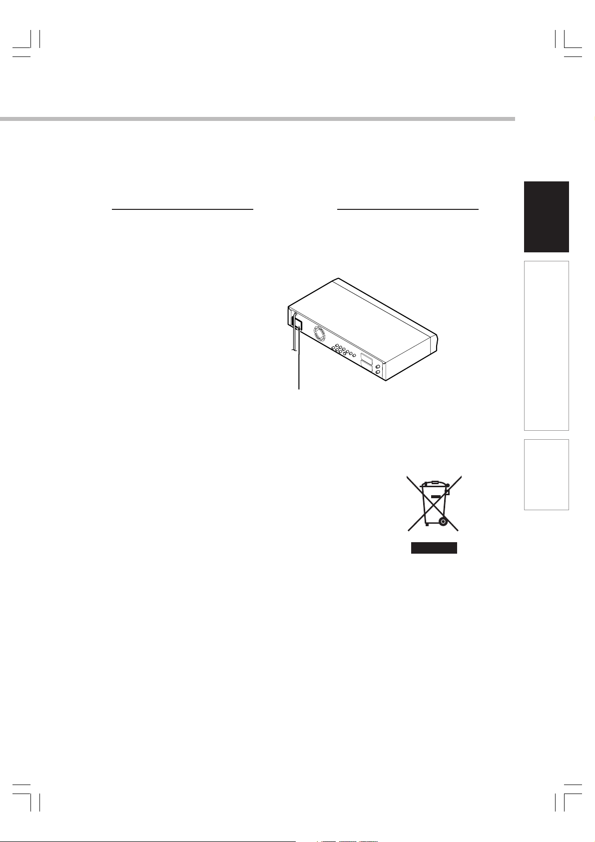
Location of the required label
The rating plate and the safety caution are on the rear of the unit.
Following information is only for EU-member states:
The use of the symbol indicates that this product may not be treated as
household waste. By ensuring this product is disposed of correctly, you will
help prevent potential negative consequences for the environment and
human health, which could otherwise be caused by inappropriate waste
handling of this product. For more detailed information about recycling of
this product, please contact your local city office, your household waste
disposal service or the shop where you purchased the product.
Introduction
Connections
Basic Setup
02_D-R150SB(E)_inst02-12 05.7.13, 0:23 AM3
3
Page 4

IMPORTANT SAFETY INSTRUCTIONS
CAUTION: PLEASE READ AND OBSERVE ALL WARNINGS AND INSTRUCTIONS GIVEN IN THIS
OWNER’S MANUAL AND THOSE MARKED ON THE UNIT. RETAIN THIS BOOKLET FOR
FUTURE REFERENCE.
This set has been designed and manufactured to assure personal safety. Improper use can result in electric
shock or fire hazard. The safeguards incorporated in this unit will protect you if you observe the following
procedures for installation, use and servicing. This unit is fully transistorized and does not contain any parts that
can be repaired by the user.
DO NOT REMOVE THE CABINET COVER, OR YOU MAY BE EXPOSED TO DANGEROUS VOLTAGE. REFER
SERVICING TO QUALIFIED SERVICE PERSONNEL ONLY.
1. Read these instructions.
2. Keep these instructions.
3. Heed all warnings.
4. Follow all instructions.
5. Do not use this apparatus near water.
6. Clean only with dry cloth.
9. Protect the power cord from being walked on or
pinched particularly at plugs, convenience
receptacles, and the point where they exit from
the apparatus.
10.Only use attachments/accessories specified by
the manufacturer.
11.Do not place a flaming object such as a burning
candle on the apparatus.
12.Unplug this apparatus during lightning storms or
when unused for long periods of time.
7. Do not block any ventilation openings. Install in
accordance with the manufacturer’s
instructions.
8. Do not install near any heat sources such as
radiators, heat registers, stoves, or other
apparatus (including amplifiers) that produce
heat.
4
02_D-R150SB(E)_inst02-12 05.7.13, 0:23 AM4
13.Refer all servicing to qualified service
personnel. Servicing is required when the
apparatus has been damaged in any way, such
as power-supply cord or plug is damaged, liquid
has been spilled or objects have fallen into the
apparatus, the unit has been exposed to rain or
moisture, does not operate normally, or has
been dropped.
Page 5

Introduction
ADDITIONAL SAFETY INSTRUCTIONS
14.Do not overload wall outlets; extension cords,
or integral convenience receptacles as this can
result in a risk of fire or electric shock.
15.Apparatus should not be exposed to dripping or
splashing and no objects filled with liquids, such
as vases, should be placed on the apparatus.
16.Keep your fingers well clear of the disc tray as
it is closing. Neglecting to do so may cause
serious personal injury.
17.Do not place anything on top of this unit.
18.Do not place the apparatus on amplifiers or
equipment that may produce heat.
20.Do not use a cracked, deformed, or repaired
disc. These discs are easily broken and may
cause serious personal injury and unit
malfunction.
21.If the apparatus should smoke or smell,
immediately disconnect the power cord from the
wall outlet. Wait until the smoke or smell stops,
then ask your dealer for a check and repair.
Neglecting to do so may cause fire.
22.During thunderstorms, do not touch the
connecting cables or the apparatus.
23.The apparatus includes lead, an ingredient of
solder used on the PCB, which is a harmful
substance to human and the environment.
When disposing of this apparatus, follow the
rules and regulations in your area.
Introduction
Connections
Basic Setup
19.Do not cover the ventilating holes for the inside
cooling fan.
02_D-R150SB(E)_inst02-12 05.7.13, 0:23 AM5
5
Page 6
Introduction
Precautions
Notes on handling
Never disconnect the power cord from a wall outlet
while the recorder is turned on, unless it is in an
emergency. Doing so may cause malfunction.
When shipping the recorder, the original shipping
carton and packing materials come in handy. For
maximum protection, repack the unit as it was
originally packed at the factory.
Do not use volatile liquids, such as insect spray, near
the recorder. Do not leave rubber or plastic products in
contact with the recorder for a long time. They will
leave marks on the finish.
The top and rear panels of the recorder may become
warm after a long time of use. This is not a
malfunction.
When not in use
For usual absence
Be sure to remove the disc from the recorder and turn
off the power.
Prolonged absence
Unplug the recorder from a wall outlet.
Notes on locating
Place the recorder on a level surface. Do not use it on
a shaky or unstable surface such as a wobbly table or
inclined stand. The loaded disc may dislodge from its
proper position and cause damage to the recorder.
Before placing the recorder, make sure that the
surface can stand the weight of the recorder. Never
place the recorder in a high location to avoid an
accidental fall of the recorder.
When you place this recorder near a TV, radio, or VTR,
the playback picture may become poor and the sound
may be distorted depending on the condition and
location of said equipment. In such an event, place the
recorder away as much as possible from the TV, radio,
or VTR.
To avoid damage to this product, never place or store
the unit in direct sunlight; hot, humid areas; or areas
subject to excessive dust, oily smoke, cigarette smoke
or vibration.
Notes on cleaning
Use a soft, dry cloth for cleaning.
Do not use any type of solvent, such as thinner or
benzine, as they may damage the surface of the
recorder.
Notes on aerials
Image and sound quality depend very much on signal
reception.
Reception may be poor in weak signal areas. In this
event, consult your dealer, or purchase a commercially
available aerial booster. Refer to the booster’s
instruction manual for installation details.
6
02_D-R150SB(E)_inst02-12 05.7.13, 0:23 AM6
Page 7
Notes on recording and editing
Power outage
When you record/edit important content, make trial
operations beforehand to confirm the recorder can
function properly.
Toshiba does not compensate for content which was
not recorded/edited because of some malfunction of
this product or discs during operation, and is not liable
for incidental damages (such as profit loss or
interruption of business, etc.) produced in such
conditions.
When the power plug is disconnected or when a
power failure occurs during any operation of this
product, all contents recorded on the disc may be
erased.
Depending on the channel or programme, an
excessive sound input level may cause noise or cut of
recorded sound. Adjust the recording level when
necessary.
If a programme you have set a timer recording includes
copy restriction signals, it may not be recorded. When
programming a recording, confirm that a programme
you want to record is not copy-restricted.
Exemptions
Toshiba is not liable for any damage caused by fires,
natural disaster (such as thunder, earthquake, etc.),
acts by a third parties, accidents, owner’s intentional
or unintentional misuse, or uses in other improper
conditions.
Toshiba is not liable for incidental damages (such as
profit loss or interruption in business, modification or
erasure of recorded data, etc.) caused by use or
inability to use of this product.
Toshiba is not liable for any damage caused by
neglect of the instructions described in the owner’s
manual.
Toshiba is not liable for any damage caused by misuse
or malfunction through simultaneous use of this
product and the connected equipment or software that
Toshiba is not concerned with.
Toshiba does not compensate for contents which were
not recorded/edited because of some malfunctions of
this product or discs during operation, and is not liable
for incidental damages (such as profit loss or
interruption in business, etc.) produced by such
conditions.
After a power outage the clock display will flash. Set
the clock to the correct time.
Notes on the unit
Do not give a shock or shake (especially during
operation).
Keep the unit horizontally.
Do not use in a place where the temperature rises or
changes rapidly.
Toshiba is not liable for any damage or loss of
recorded data caused by shock, shakes, misoperation
or malfunction.
Introduction
Connections
Basic Setup
02_D-R150SB(E)_inst02-12 05.7.13, 0:23 AM7
7
Page 8
Introduction
Precautions (Continued)
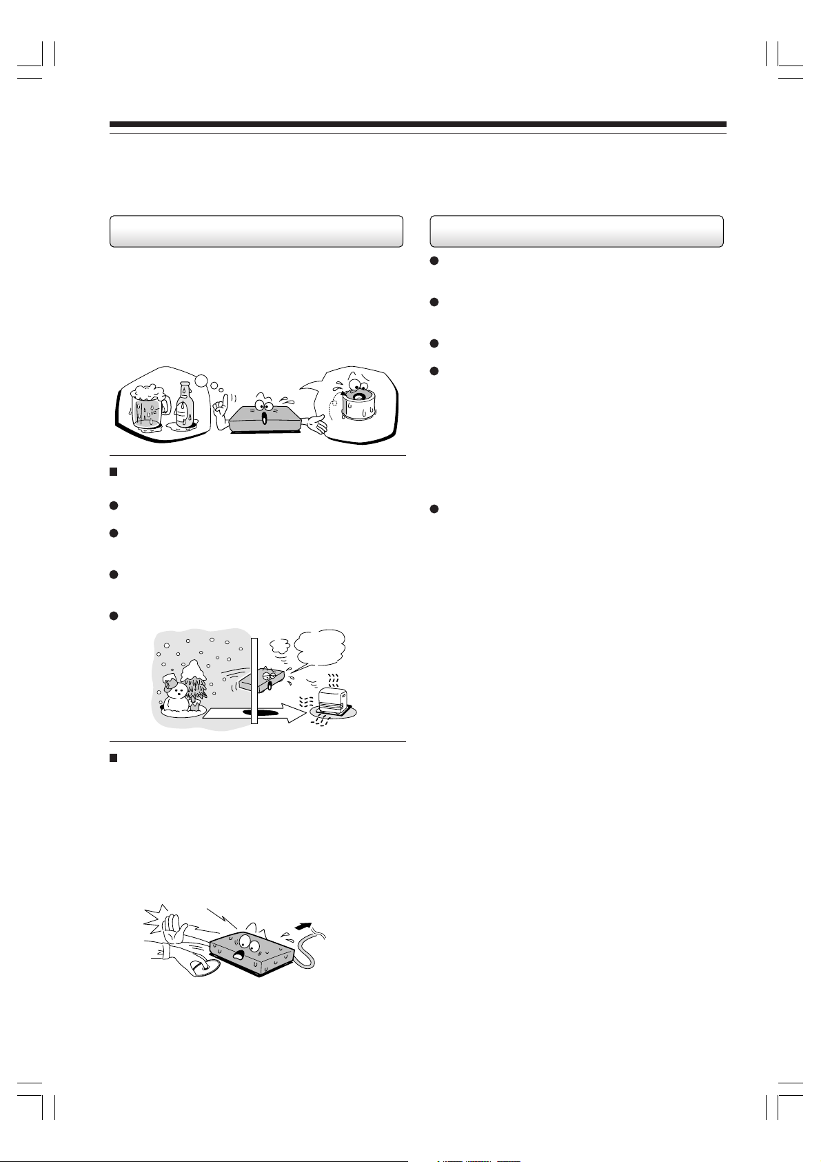
Notes on moisture condensation
Moisture condensation damages the unit. Please
read the following carefully.
Moisture condensation occurs, for example, when you
pour a cold drink into a glass on a warm day. Drops of
water form on the outside of the glass. In the same way,
moisture may condense on the optical pick-up lens inside
this unit, one of the most crucial internal parts of the unit.
f
o
m
e
o
l
p
i
s
m
a
x
E
n
o
c
Moisture condensation occurs during the
following cases.
When you bring the unit directly from a cold place to a
warm place.
When you use the unit in a room where you just
turned on the heater, or a place where the cold wind
from the air conditioner directly hits the unit.
In summer, when you use the unit in a hot and humid
place just after you move the unit from an air
conditioned room.
When you use the unit in a humid place.
t
u
r
e
s
n
a
e
t
i
d
o
n
!
Optical pick-up
lens
Notes on copyright
It is prohibited by law to copy, broadcast, show,
broadcast on cable, play in public, and rent
copyrighted material without permission.
It is permissible to record television programmes, film,
video tapes and other material only in the event that
third party copyrights and other rights are not violated.
Some DVD video discs are copy protected, and any
recordings made from these discs will be distorted.
This product incorporates copyright protection
technology that is protected by method claims of
certain U.S. patents and other intellectual property
rights owned by Macrovision Corporation and other
rights owners. Use of this copyright protection
technology must be authorized by Macrovision
Corporation, and is intended for home and other
limited viewing uses only unless otherwise authorized
by Macrovision Corporation. Reverse engineering or
disassembly is prohibited.
This unit incorporates CPRM (Content Protection for
Recordable Media) technology for copyright protection
in recording devices, authorized by DVD forum.
Recording and copying on this recorder depend on the
contents as described next page.
It’s too
warm!
Do not use the unit when moisture condensation
may occur in the situations above.
If you use the unit in such a situation, it may damage
discs and internal parts. Connect the power cord of
the unit to the wall outlet, turn on the unit, remove the
disc, and leave it for two or three hours. After two or
three hours, the unit will have warmed up and
evaporated any moisture. Keep the unit connected to
the wall outlet and moisture condensation will seldom
occur.
Wait!
Wall outlet
8
02_D-R150SB(E)_inst02-12 05.7.13, 0:23 AM8
Page 9
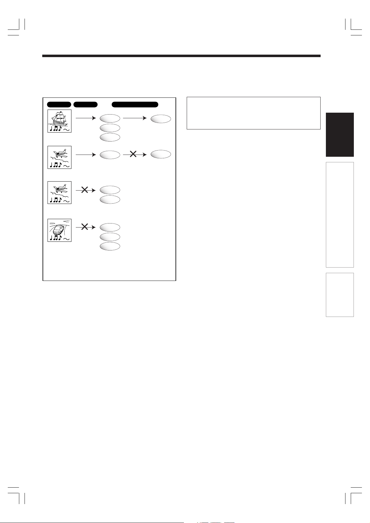
Programme Recording
Can be
recorded
Copy free
Copy within the same disc
DVD-RAM
DVD-RW
DVD-R
Can be
copied
DVD-RAM
Manufactured under license from QSound Labs, Inc. U.S.
patent Nos. 5,105,462, 5,208,860 and 5,440,638 and
various foreign counterpart. Copyright QSound Labs, Inc.
1998-2002. QXpander
TM
is a trademark of QSound Labs,
Inc. All rights reserved.
Introduction
DVD-RAM
Recording once
permitted
Recording once
permitted
Recording
prohibited
Can be
recorded
Cannot be
recorded
Cannot be
recorded
DVD-RAM
DVD-RW
DVD-R
DVD-RAM
DVD-RW
DVD-R
Cannot be
copied
• Regardless of programme content, copies cannot
be made within the same DVD-RW disc or DVD-R
disc.
Connections
Basic Setup
02_D-R150SB(E)_inst02-12 05.7.13, 0:23 AM9
9
Page 10
Introduction
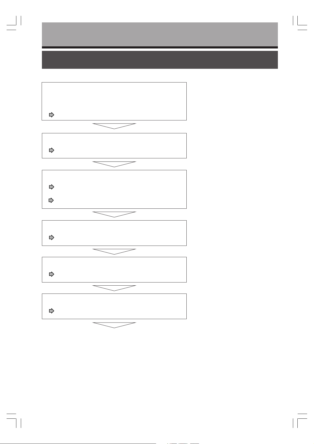
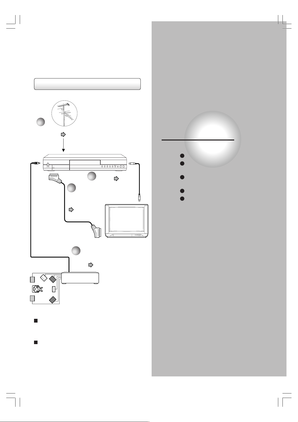
Installation procedure
Read carefully “SAFETY PRECAUTIONS”,
“IMPORTANT SAFETY INSTRUCTIONS” and
“Precautions”.
( pages 2 to 9)
Load the batteries in the remote control.
( page 12)
Connect an aerial to the recorder.
( page 14)
Connect a satellite receiver to the recorder.
( pages 18 to 19)
Connect the recorder to a TV.
( pages 14 to 17)
Connect optional equipment to the recorder.
( page 20)
Make the initial settings.
( page 24)
Your recorder is ready. Read the separate
volume “OPERATIONS GUIDE”.
10
02_D-R150SB(E)_inst02-12 05.7.13, 0:23 AM10
Page 11
Introduction
Table of contents
Introduction
SAFETY PRECAUTIONS ...................................................................................................... 2
IMPORTANT SAFETY INSTRUCTIONS ............................................................................... 4
Precautions........................................................................................................................... 6
Installation procedure........................................................................................................ 10
Preparation of the remote control .................................................................................... 12
Connections
Connecting an aerial and TV ............................................................................................. 14
Connecting to a TV equipped with phono type jacks ..................................................... 16
Connecting to a TV equipped with component video inputs ......................................... 17
Connecting a satellite receiver ......................................................................................... 18
Connecting to an audio system ........................................................................................ 20
Basic Setup
Starting up the recorder .................................................................................................... 22
A: Initial settings ................................................................................................................ 24
B: Output sound setting .................................................................................................... 40
C: TV shape setting ............................................................................................................ 42
D: Remote control settings ............................................................................................... 44
Introduction
Connections
By using SCART cable .......................................................................................... 18
By using RF coaxial cable ..................................................................................... 19
Basic Setup
1: Time and date setting ........................................................................................ 26
2: Channel setting .................................................................................................. 29
3: Just clock setting ............................................................................................... 35
4: Input signal setting............................................................................................. 37
5: AV1 output setting ............................................................................................. 38
6: AV2 input setting ................................................................................................ 39
Operating a TV with the remote control of this recorder........................................ 44
Operating the second and third TOSHIBA DVD video recorders with
the remote control of this recorder ........................................................................ 46
02_D-R150SB(E)_inst02-12 05.7.13, 0:23 AM11
11
Page 12
Introduction
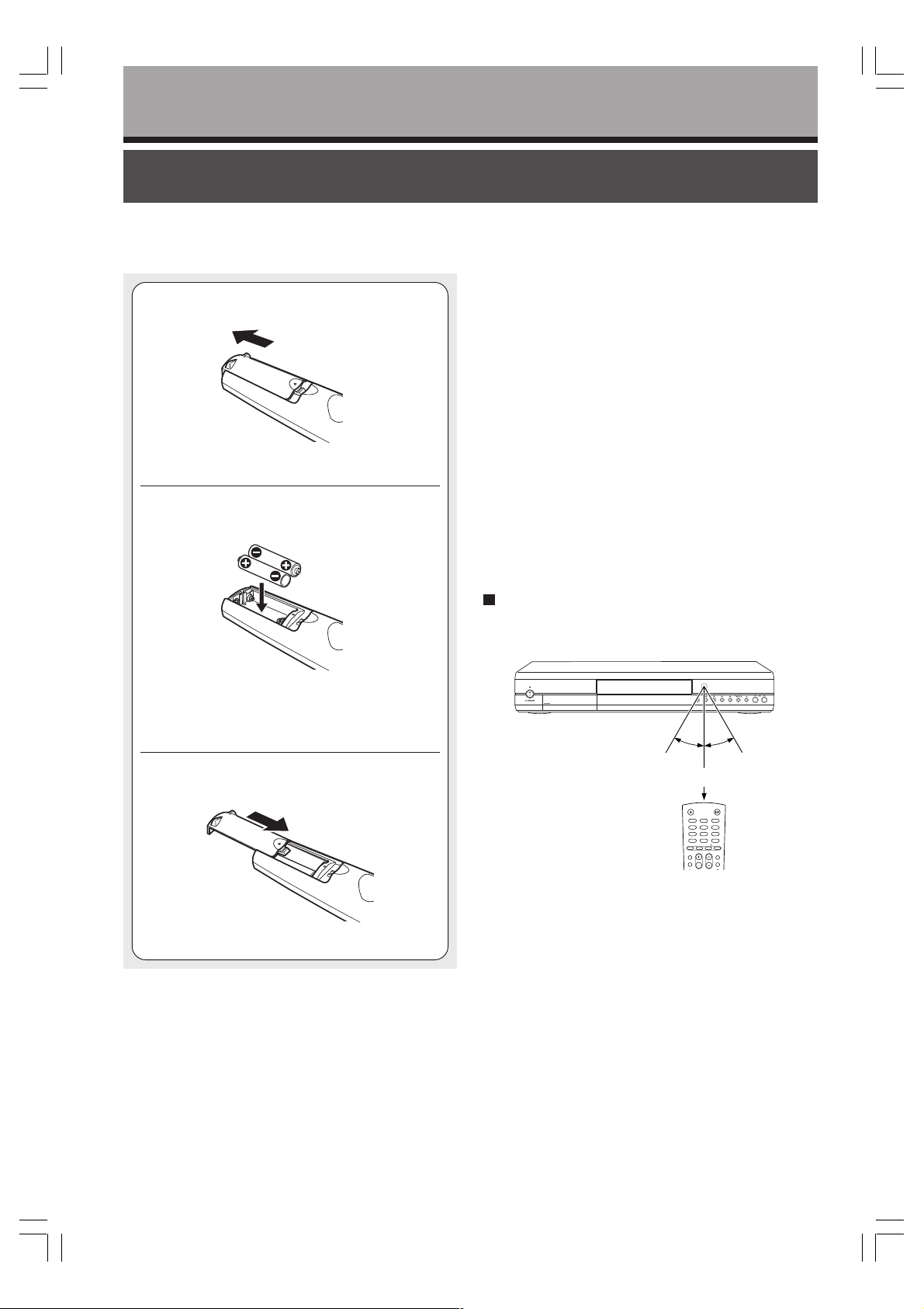
Preparation of the remote control
Notes on batteries
Open the cover.
1
Insert batteries (R6 type).
2
Improper use of batteries may cause battery leakage and
corrosion. To operate the remote control correctly, follow the
instructions below.
• Do not insert batteries into the remote control in the wrong
direction.
• Do not charge, heat, open, or short-circuit the batteries. Do
not throw batteries into a fire.
• Do not leave dead or exhausted batteries in the remote
control.
• Do not use different types of batteries together, or mix old
and new batteries.
• If you do not use the remote control for a long period of
time, remove the batteries to avoid possible damage from
battery corrosion.
• If the remote control does not function correctly or if the
operating range is reduced, replace all batteries with new
ones.
• If battery leakage occurs, wipe the battery liquid from the
battery compartment, then insert new batteries.
Make sure to match the + and – on the
batteries to the marks inside the battery
compartment.
Close the cover.
3
Operating with the remote control
Point the remote control at the remote sensor and
press the buttons.
30°
30°
Within about 7 m
OPEN/CLOSE
ON/STANDBY
1
3
2
456
89
7
+
CLEAR
0
10
INPUT SEL.
TIME SLIP
DVD TV
CH
TV VOL
T.SEARCH
PROGRESSIVE
TOP MENU
MENU
SKIP FWDSKIP REV
Distance : About 7 m from the front of the remote
sensor
Angle : About 30° in each direction of the front of
the remote sensor
* Do not expose the remote sensor of the recorder to a
strong light source such as direct sunlight or other
illumination. If you do so, you may not be able to
operate the recorder via the remote control.
12
02_D-R150SB(E)_inst02-12 05.7.13, 0:23 AM12
Notes
• Do not drop or give the remote control a shock.
• Do not leave the remote control near an extremely hot or
humid place.
• Do not spill water or put anything wet on the remote control.
• Do not disassemble the remote control.
Page 13
Connection procedure
1
“Connecting an aerial
and TV” ( page 14)
“Connecting an aerial
2
and TV” ( page 14)
3
“Connect to a TV
equipped with
SCART inputs”
( page 15)
Connections
Connect your recorder to your TV and/or audio system.
Connecting an aerial and TV
Connecting to a TV equipped
with phono type jacks
Connecting to a TV equipped
with component video inputs
Connecting a satellite receiver
Connecting to an audio system
4
“Connecting to an audio
system” ( page 20)
AV amplifier
When you connect a TV equipped with SCART
inputs
Perform steps 1, 2 and 3.
When you connect an audio system
Perform steps 1, 2, 3 and 4.
03_D-R150SB(E)_inst_13-20 05.7.13, 0:23 AM13
Page 14
Connections
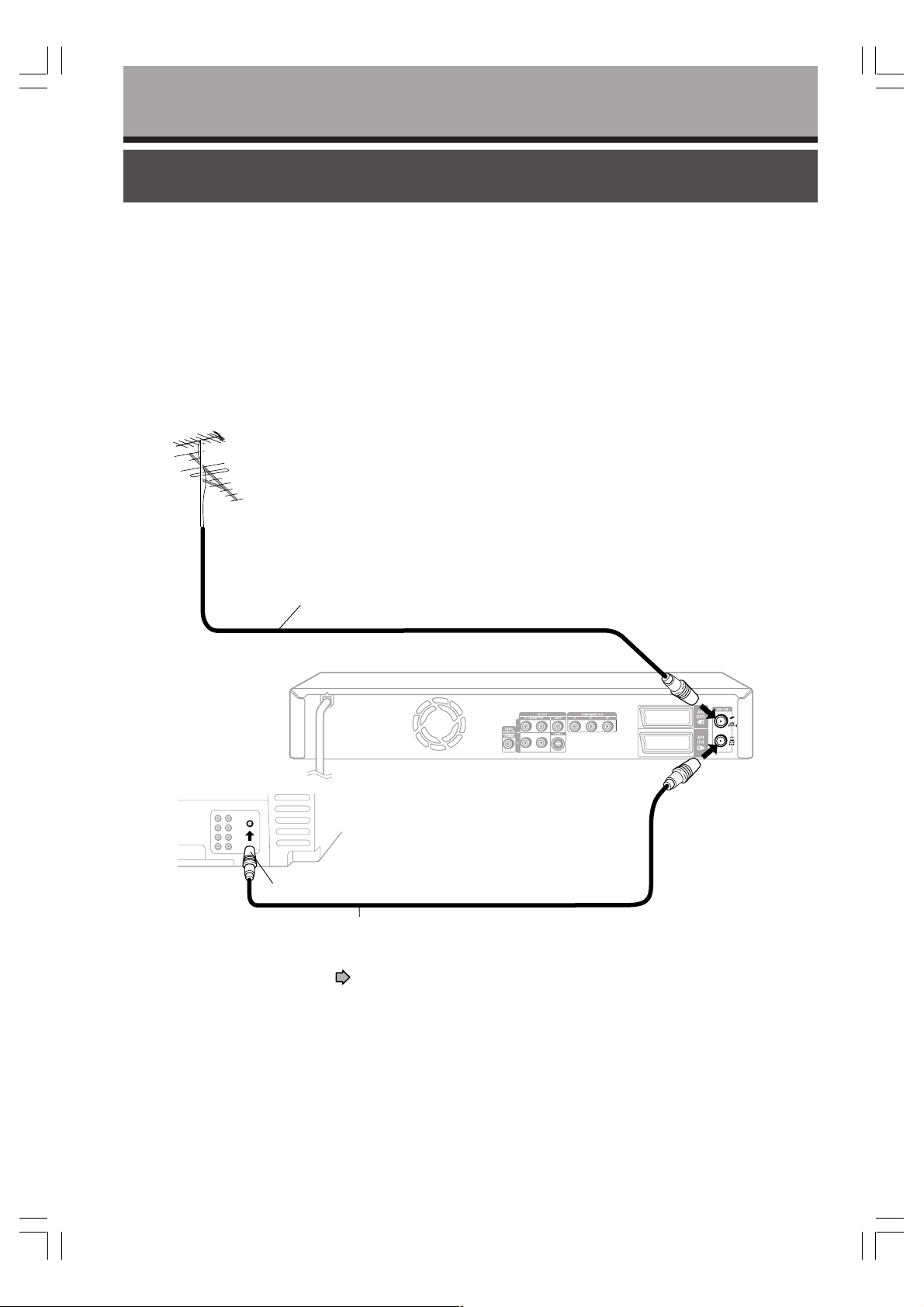
Connecting an aerial and TV
Connect your TV and the aerial to this recorder for recording and to view broadcast programmes on the TV.
Disconnect the aerial cable from your TV, and connect it to the VHF/UHF RF
IN (FROM ANT.) terminal on the recorder.
1
Connect the VHF/UHF RF OUT (TO TV) terminal to the TV by using the
supplied coaxial cable.
2
VHF/UHF aerial
Aerial cable
To aerial input
2
Coaxial cable (supplied)
For connecting a satellite system, see page 18.
To VHF/UHF RF IN (FROM ANT.)
To VHF/UHF RF OUT (TO TV)
1
2
14
03_D-R150SB(E)_inst_13-20 05.7.13, 0:23 AM14
Page 15
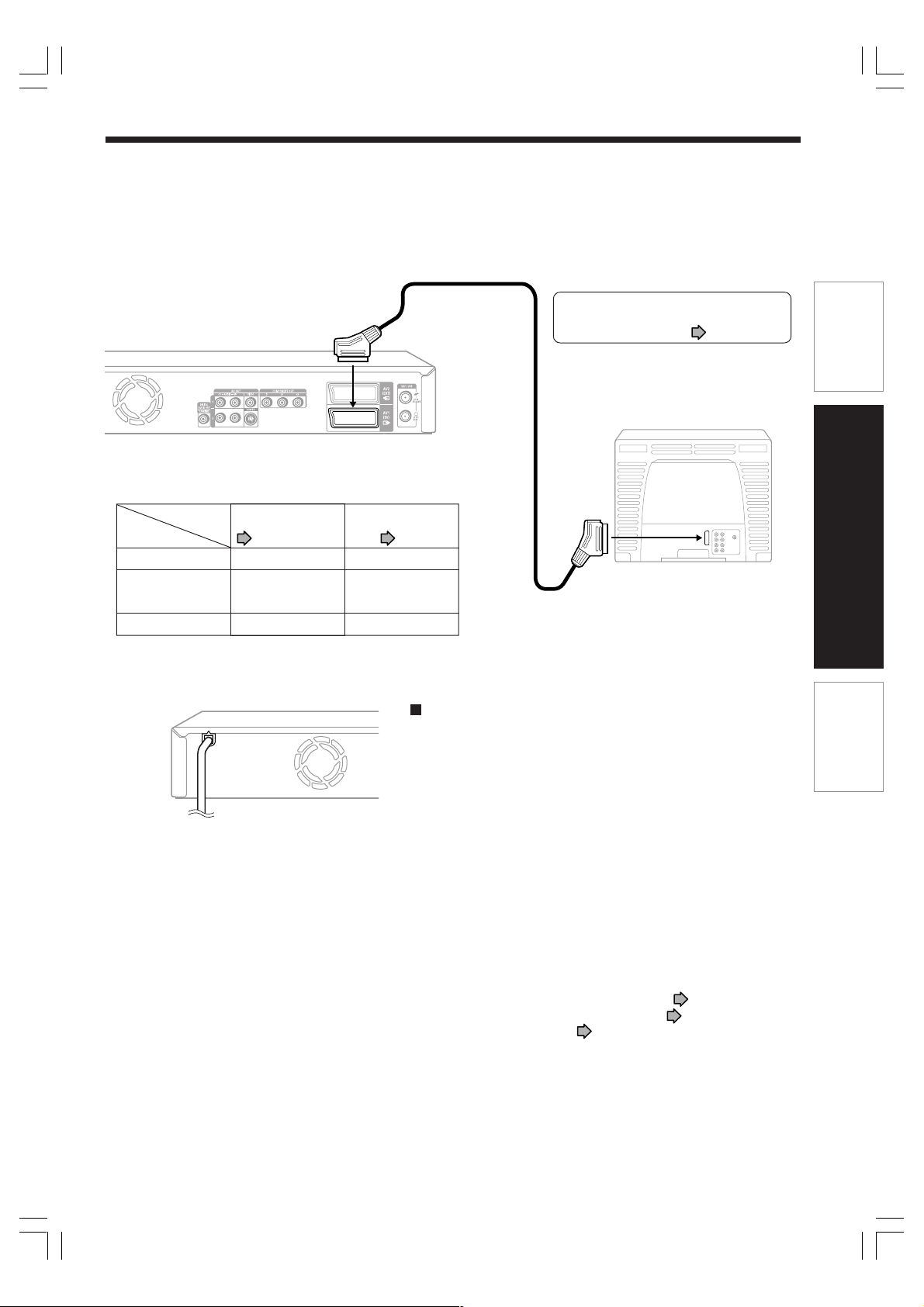
Connect to a TV equipped with SCART inputs.
Connect as below for watching received channels or recorded contents. Watching via the RF OUT terminal
3
is not available.
SCART cable (not supplied)
To AV1(TV)
• The following setting is required according to the TV that
you are connecting. Perform this setting after step 4.
Setting
“AV1 output” on the
“Initial settings” menu.
TV
Normal TV “Video”
page 38
“Audio out select” on the
“Picture/Audio settings”
menu.
page 40
“Analog 2ch”
For connections to TVs with no SCART
inputs, see “Connecting to a TV equipped
with phono type jacks” ( page 16).
• Normal TV
• TV compatible with S video signals
• RGB monitor
Introduction
Connections
TV compatible with
S video signals
RGB monitor “RGB”
“S-Video”
“Analog 2ch”
To SCART input
“Analog 2ch”
Connect the power cord of the recorder to a wall outlet.
4
To wall outlet
Notes
• Refer to the owner’s manual of the connected TV as well.
• When you connect the recorder to your TV, be sure to turn off the power and unplug both units from the wall outlet before any
connections.
• Connect the recorder directly to your TV. If you connect the recorder via a VTR, TV/VTR combination or video selector, the
playback picture may be distorted due to copy protection.
Plug & Auto Set Up function
This recorder will automatically set itself up when it is plugged
into the mains for the first time.
TV stations will be stored in the recorder’s memory. The process
will finish after a few minutes. Then the date and time are set
automatically from broadcast signal.
Notes
• The display on the recorder shows “Auto” while the Plug & Auto Set
Up function is running.
• TV stations are stored in the range of UHF E21-E69.
• You can only use the ON/STANDBY button and OPEN/CLOSE button
while the Plug & Auto Set Up function is running.
• The automatic setup is cancelled, if you press the ON/STANDBY
button while the Plug & Auto Set Up function is running.
• The Plug & Auto Set Up function may not work, depending on the
radio reception or other conditions. In this case, refer to “Initial
settings” in this Owner’s Manual for the setup.
To use the phono type jacks to connect the TV ( page 16), to use
the component video jacks to connect the TV ( page 17), or to
connect the satellite receiver ( pages 18, 19) complete the
necessary connection before connecting the power cord.
Basic Setup
03_D-R150SB(E)_inst_13-20 05.7.13, 0:23 AM15
15
Page 16

Connections
Connecting to a TV equipped with phono type jacks
Select the connection type depending on the TV. (Normal TV/TV equipped with an S video input)
Normal TV
To video
input
(yellow)
To S video
input
To audio
input
TV equipped with
an S video input
To audio
input
Video/Audio cable (supplied)
Audio cable (not supplied)
S video cable (not supplied)
To AV OUT AUDIO
(R: red, L: white)
• The following setting is required according to the TV
that you are connecting. Perform this setting after step 4
(
page 15).
Setting
“AV1 output” on the
“Initial settings” menu.
TV
Normal TV No need to set.
page 38
“Audio out select” on the
“Picture/Audio settings”
menu.
page 40
“Analog 2ch”
To AV OUT AUDIO
(R: red, L: white)
To AV OUT VIDEO
(yellow)
To AV OUT S-VIDEO
TV equipped with an
S video input
No need to set.
“Analog 2ch”
Note
• If your television set has one audio input, connect the left and right audio outputs of the recorder to a Y cable adapter (not
supplied) and then connect to your TV.
16
03_D-R150SB(E)_inst_13-20 05.7.13, 0:23 AM16
Page 17

Connections
Connecting to a TV equipped with component video inputs
If your TV has component video inputs, you can obtain pictures in better quality.
TV or monitor equipped with
component video inputs
To Y video input
To P
B video input
To P R video input
To AV OUT AUDIO
(R: red)
Video cable (not supplied)
To
COMPONENT
OUT P
R
Component video outputs/inputs
Some TVs or monitors are equipped with component
video inputs. Connecting to these inputs allows you to
enjoy higher quality picture playback.
Actual labels for component video inputs may vary
depending on the TV manufacturer. (ex.Y, R-Y, R-B or
Y, C
B, CR)
In some TVs or monitors, the color levels of the
playback picture may be reduced slightly or the tint
may change. In such a case, adjust the TV or monitor
for optimum performance.
To switch the output signal (Progressive/Interlaced)
PROGRESSIVE
Press PROGRESSIVE on the remote
control.
The output signal alternates between
component progressive and component
interlaced.
• When “PSO” is displayed on the front panel
display, the output signal is progressive. When
“PSO” is not displayed, the output signal is
interlace.
To
COMPONENT
OUT P
To
COMPONENT
OUT Y
To AV OUT AUDIO
(L: white)
Audio cable (not supplied)
B
To audio inputs of the amplifier
(white)(red)
• The following setting is required according to the TV
that you are connecting. Perform this setting after step
page 15).
4 (
Setting
TV
TV or monitor
equipped with
component video
inputs
“AV1 output” on the
“Initial settings” menu.
page 38
“Video” or “S-Video”
“Audio out select” on the
“Picture/Audio settings”
menu.
page 40
“Analog 2ch”
• Selecting “RGB” disables signal output from the
COMPONENT OUT (Y, P
B, PR) jacks. If the on-screen
display disappears immediately after you select “RGB”,
you can restore it by connecting the recorder using the
AV OUT VIDEO (yellow) jack.
• If you display the setup menu when the output signal is
progressive, it automatically changes to interlace.
Press PROGRESSIVE again after you exit the menu.
Introduction
Connections
Basic Setup
Notes
• Refer to the owner’s manual of the connected TV as well.
• When you connect the recorder to other equipment, be sure to turn off the power and unplug all of the equipment from the
wall outlet before any connections.
• If you place the recorder near a tuner or radio, the radio broadcast sound might be distorted. In this event, place the recorder
away from the tuner and radio.
• The output sound of the recorder has a wide dynamic range. Be sure to adjust the amplifier’s volume to a moderate listening
level. Otherwise, the speakers and your hearing may be damaged by a sudden high volume sound.
• Turn off the amplifier before you connect or disconnect the recorder’s power cord. If you leave the amplifier power on, the
speakers may be damaged.
• Consumers should note that not all high definition television sets are fully compatible with this product and may cause
artifacts to be displayed in the picture. In case of 625 progressive scan picture problems, it is recommended that the user
switch the connection to the “Standard Definition” output. If there are questions regarding our TV set compatibility with this
model 625p DVD player, please contact our Customer Service Center.
03_D-R150SB(E)_inst_13-20 05.7.13, 0:23 AM17
17
Page 18

Connections
Connecting a satellite receiver
You can connect a satellite receiver to this recorder to enjoy watching or recording satellite programmes
through the recorder.
By using SCART cable
If both your TV and satellite receiver have a SCART input, use a SCART cable to connect the recorder.
SCART cable
(not supplied)
VHF/UHF aerial
Satellite receiver
To AV2(EXT)
To AV1(TV)
SCART cable (not supplied)
To SCART input
TV
Notes
• To watch broadcast programmes by using the satellite receiver, use INPUT SEL. button on the remote control and select
“AV2 ” (this is shown on the display on the recorder).
• According to the type of the TV set that you are connecting, set the output for the AV1(TV) socket. ( page 38)
• According to the type of video output signal used for the satellite receiver that you are connecting, set “AV2 input” with “Initial
settings”. ( page 39)
To aerial input
18
03_D-R150SB(E)_inst_13-20 05.7.13, 0:23 AM18
Page 19

By using RF coaxial cable
After making this connection, you must allocate a channel on the recorder to receive satellite stations.
Introduction
Satellite receiver
To SCART input
RF IN
RF OUT
SCART cable (not supplied)
Aerial
Connections
To AV1(TV)
Basic Setup
To aerial input
03_D-R150SB(E)_inst_13-20 05.7.13, 0:23 AM19
TV
19
Page 20

Connections
Connecting to an audio system
You can enjoy multichannel surround-sound such as 5.1 channel by connecting to an amplifier
compatible with Dolby Digital and DTS sound.
• For connection to your TV, see pages 14 to 17.
• For details of output sound, see
CAUTION
• When you are connecting (via the DIGITAL AUDIO OUT COAXIAL jack) an AV decoder that does not have Dolby
Digital, Digital Theater Systems (DTS) or MPEG2 decoding function, be sure to set “Audio out select” to “PCM” from the
on-screen displays ( page 40). Otherwise, high volume sound may damage your hearing as well as the speakers.
• When playing DTS-encoded discs (DVD video discs and audio CDs), excessive noise may be output from the analog
stereo jacks. To avoid possible damage to the audio system, you should take proper precautions when the AV OUT
AUDIO (L/R) jacks of the recorder are connected to an amplification system. To enjoy DTS Digital Surround® playback,
an external 5.1 channel DTS Digital Surround® decoder system must be connected to the DIGITAL AUDIO OUT
COAXIAL jack of the recorder.
page 112 in “OPERATIONS GUIDE”.
Amplifier
To COAXIAL
type digital
audio input
To DIGITAL AUDIO
75 Ω coaxial cable (not supplied)
Manufactured under license from Dolby Laboratories. “Dolby”
and the double-D symbol are trademarks of Dolby Laboratories.
“DTS” and “DTS Digital Out” are trademarks of Digital Theater
Systems, Inc.
Notes
• DO NOT connect the DIGITAL AUDIO OUT COAXIAL jack of the recorder to the AC-3 RF input of a Dolby Digital Receiver.
This input on your A/V Receiver is reserved for Laserdisc use only and is incompatible with the DIGITAL AUDIO OUT
COAXIAL jack of the recorder.
• Connect the DIGITAL AUDIO OUT COAXIAL jack of the recorder to the “COAXIAL” input of a receiver or processor.
• Refer to the owner’s manual of the connected equipment as well.
• When you connect the recorder to other equipment, be sure to turn off the power and unplug all of the equipment from the
wall outlet before any connections.
• The output sound of the recorder has a wide dynamic range. Be sure to adjust the audio amplifier’s volume to a moderate
listening level. Otherwise, the speakers and your hearing may be damaged by a sudden high volume sound.
• Turn off the amplifier before you connect or disconnect the recorder’s power cord. If you leave the amplifier power on, the
speakers may be damaged.
• Make the setting on page 40, “Audio out select”.
OUT COAXIAL
20
03_D-R150SB(E)_inst_13-20 05.7.13, 0:23 AM20
Page 21

Basic Setup
Read this chapter for necessary settings to get started.
When you use this recorder for the first time, be sure to
perform A to C in this order.
Proceed to D if necessary.
Starting up the recorder
A: Initial settings
1: Time and date setting
2: Channel setting
3: Just clock setting
– Clock set position
setting
4: Input signal setting
5: AV1 output setting
6: AV2 input setting
B: Output sound setting
C: TV shape setting
D: Remote control settings
04_D-R150SB(E)_inst_21-33 05.7.13, 0:23 AM21
Operating a TV with the
remote control of
this recorder
Operating the second and
third TOSHIBA DVD video
recorders with the remote
control of this recorder
Page 22

Basic Setup
Starting up the recorder
While the icon is flashing, the recorder is checking
After all the necessary connections,
• Turn on the equipment connected to the
recorder.
• Select the corresponding video input on
your TV.
Perform these selections whenever you operate
the recorder.
the status and reading data of the DVD drive for
startup. If the DVD drive does not contain a disc,
the recorder consumes less time to startup,
because it does not need to read data from the
DVD drive.
While the “Loading” icon is flashing, the recorder
cannot respond to any operations. Operate after the
icon has disappeared.
Note
When the recorder is turned on for the first time, the
following menu may be displayed after the “Loading” icon
has disappeared. See “A: Initial settings” ( page 24).
Turning the power on
Press ON/STANDBY button from the remote control or
on the front panel of the recorder.
ON/STANDBY button
OPEN/CLOSE
ON/STANDBY
ON/STANDBY button
1
3
2
4
6
5
89
7
+
CLEAR
0
10
DVD TV
TV VOL
INPUT SEL.
CH
TIME SLIP
When the power turns on, the display of the front
panel shows “ON”.
After a few seconds, a startup screen appears.
The following icon will appear on the top right corner
of the screen. The icon will continue flashing
momentarily.
e.g.
Time & date setting
Channel setting
Input signal
AV1 output
AV2 input
Clock set position
Just clock
Initial settings
Auto
Auto
PAL
Video
Video
1
On
Turning the power off
Press ON/STANDBY button from the remote control or
on the front panel of the recoder.
The “Unloading” icon appears on the right corner of
the top of the screen, and the display of the front panel
shows “OFF”. Then the power turns off.
Note
• If the recorder freezes for about 15 minutes and will not
respond to any buttons, holding down ON/STANDBY
button on the front panel for about 10 seconds can force
the recorder to turn off. However, this is an emergency
measure, which contains a risk of damage to data or discs.
Avoid casual use of this measure.
e.g.
22
04_D-R150SB(E)_inst_21-33 05.7.13, 0:23 AM22
Loading
Page 23

Startup/finishing (closing) icons
These icons are displayed on the right corner on the
top of the screen. While they are flashing, the recorder
is operating as follows:
Startup, reading a disc, finishing
Loading
recording
Introduction
Un
loading
Open
Close
Unloading a disc, finishing the recorder’s
operation
Opening a disc tray
Connections
Closing a disc tray
Basic Setup
04_D-R150SB(E)_inst_21-33 05.7.13, 0:23 AM23
23
Page 24

Basic Setup
A: Initial settings
This step sets the recorder’s clock and tuner to record broadcasting TV programmes.
If there are discrepancies in the recorder’s time display or changes made to receivable TV stations, you
should make this setting again.
OPEN/CLOSE
1
4
7
+
10
TIME SLIP
T.SEARCH
TOP MENU
INSTANT
TV VOL
STOP
REV
PAUSE
REPLAY
QUICK
2
5
89
0
DVD TV
CH
PLAY
Start
ADJUST
ENTER
ON/STANDBY
3
6
CLEAR
INPUT SEL.
PROGRESSIVE
MENU
SKIP FWDSKIP REV
FWD
EASY
NAVI
INSTANT
SKIP
CHP DIVIDE
If the setup menu is not displayed, press EASY NAVI and
1
select “Setup” using
/ / / , then press ENTER to
display the menu.
Press / to select “Initial settings”, then
press ENTER.
2
e.g.
ENTER
Time & date setting
Channel setting
Input signal
AV1 output
AV2 input
Clock set position
Just clock
Initial settings
Auto
Auto
PAL
Video
Video
1
On
Press / to select the setting to be adjusted,
then press ENTER.
3
The submenu appears.
ENTER
e.g. When “Time & date setting” is selected:
e.g.
Time & date setting
Channel setting
Input signal
AV1 output
AV2 input
Clock set position
Just clock
Initial settings
Auto
Auto
PAL
Video
Video
1
On
Auto
Manual
DISPLAY
REC
TV/DVR
REC MODE
SUBTITLE
ZOOM ANGLE
AUDIO
When the recorder is operated for the first time, input
settings in the following order.
1: Time & date setting
2: Channel setting
3: Just clock setting
page 26
page 29
page 35
Clock set position setting
4: Input signal setting
5: AV1 output setting
6: AV2 input setting
• If you display the setup menu when the output signal is progressive, it
automatically changes to interlace. Press PROGRESSIVE again after you exit
the menu. page 17
Notes
• To go back to the previous menu, press button.
• To exit the menu, press EASY NAVI button twice.
• If you exit the “Initial settings” menu when the clock and channels are not set, a menu may automatically appear to remind
you to set them each time you turn on the recorder. Once you complete this process, the menu reminder will not appear
again.
• When the power goes down or the power cord is unplugged, the clock data, channel data and timer programmes may be
deleted. In this case, set up these items again.
page 37
page 38
page 39
24
04_D-R150SB(E)_inst_21-33 05.7.13, 0:23 AM24
Page 25

Tip on setting
The recorder provides you with a variety of GUI
(Graphical User Interface) displays to perform key
operations including customizing of setting, playback
or recording.
Refer to the guide on the bottom on each GUI for
further programming related informations.
e.g.
If a message appears
The recorder may display a message. Each message
varies according to operational status.
To respond, follow the below examples.
Message
e.g.
Introduction
Time & date setting
Channel setting
Input signal
AV1 output
AV2 input
Clock set position
Just clock
Direction buttons
O button
ENTER button
SETUP
EASY NAVI button
Initial settings
Auto
Auto
PAL
Video
Video
1
On
Operation guide
ExitSelect SetReturn
SETUP
FunctionExample of the icon
To select an item.
To return to the previous
page.
To enter (confirm) a
selected item or setting.
To display/exit a setting
menu.
e.g.
e.g.
message
No
OK
Yes
2 selections
message
OK
1 selection
message
OK
Set
Select either response (by
highlighting in green) using the
/ buttons, then press
ENTER button.
The message disappears.
Read the message, then press
ENTER button.
The message disappears.
Connections
Basic Setup
04_D-R150SB(E)_inst_21-33 05.7.13, 0:23 AM25
e.g.
The message disappears
automatically in a few seconds.
message
No selection
25
Page 26

Basic Setup
A: Initial settings (Continued)
1: Time and date setting
Set the recorder’s clock. If it is not set correctly, the recorder cannot perform operations other than playback.
OPEN/CLOSE
1
4
7
+
10
TIME SLIP
T.SEARCH
TOP MENU
INSTANT
TV VOL
REV
PAUSE
REPLAY
QUICK
2
5
89
0
DVD TV
STOP
PLAY
Start
ADJUST
ENTER
ON/STANDBY
3
6
CLEAR
INPUT SEL.
CH
PROGRESSIVE
MENU
SKIP FWDSKIP REV
EASY
CHP DIVIDE
FWD
NAVI
INSTANT
SKIP
If the setup menu is not displayed, press EASY NAVI and
1
select “Setup” using / / / , then press ENTER to
display the menu.
Press / to select “Initial settings”, then press ENTER.
2
Press / to select “Time & date setting”,
then press ENTER.
3
e.g.
ENTER
Time & date setting
Channel setting
Input signal
AV1 output
AV2 input
Clock set position
Just clock
Initial settings
Auto
Auto
PAL
Video
Video
1
On
Auto
Manual
Press / to select “Auto” or “Manual”, then
press ENTER.
4
Auto : You can be free of entering each value.
ENTER
Proceed to the next page.
(This function will not work correctly unless the
“Clock set position” is set correctly.
36)
Page
DISPLAY
REC
REC MODE
ZOOM ANGLE
TV/DVR
26
04_D-R150SB(E)_inst_21-33 05.7.13, 0:23 AM26
SUBTITLE
AUDIO
Manual : You can set the clock manually. See “Manual
Select “Manual” to set the clock if not set correctly by
“Auto”.
clock setting”
page 28
Page 27

Auto (Auto clock setting)
When you select “Auto” and press ENTER button at step 4, the Auto
clock setting function starts.
e.g.
Auto Time & Date Scanning.
• When the setting is complete, the “Initial settings”
menu returns.
(Continued)
Note
• The Auto clock setting function may not work, depending on the radio reception or other conditions. If the Auto clock setting
function does not work successfully, use the “Manual” clock setting menu to enter the time and date.
• This function does not work when the channel setting is not complete or the channel at position 1 does not have the clock
information. ( page 31)
Introduction
Connections
Basic Setup
04_D-R150SB(E)_inst_21-33 05.7.13, 0:23 AM27
27
Page 28

Basic Setup
A: Initial settings (Continued)
OPEN/CLOSE
1
4
7
+
10
TIME SLIP
T.SEARCH
TOP MENU
INSTANT
TV VOL
REV
PAUSE
REPLAY
QUICK
2
5
89
0
DVD TV
STOP
PLAY
ADJUST
ENTER
ON/STANDBY
3
6
CLEAR
INPUT SEL.
CH
PROGRESSIVE
MENU
SKIP FWDSKIP REV
EASY
CHP DIVIDE
FWD
NAVI
INSTANT
SKIP
Manual (Manual clock setting)
Select “Manual”, then press ENTER at step 4 page 26.
e.g.
Manual clock set
Year
2005
Date Time
41
21 (Th) 3016 :
/
Press / and ADJUST (– / +) to set the clock.
5
/ buttons:
To select “Year”, “Date”, “Time”.
ENTER
ADJUST
ADJUST (– / +) buttons:
To change the data.
(
/ buttons can also be used in addition to the
ADJUST(– / +) buttons.)
After setting all the items, press ENTER.
6
The following message appears.
DISPLAY
REC
TV/DVR
REC MODE
ZOOM ANGLE
SUBTITLE
AUDIO
ENTER
Set date and time?
Yes No
Press / to select “Yes ”, then press ENTER.
7
The “Initial settings” menu returns.
ENTER
Notes
• This recorder is provided with a calendar extending to 2069. (However, this does not mean that the recorder is supported to
2069.)
• To go back to the previous menu, press button.
• To exit the menu, press EASY NAVI button twice.
“1: Time and date setting” is complete. Go to “2: Channel setting”. ( page 29)
28
04_D-R150SB(E)_inst_21-33 05.7.13, 0:23 AM28
Page 29

2: Channel setting
This recorder contains a built-in tuner used to receive television broadcasts.
You must preset the stations received through the tuner.
Introduction
OPEN/CLOSE
1
4
7
+
10
TIME SLIP
REV
PAUSE
INSTANT
REPLAY
QUICK
TV VOL
STOP
T.SEARCH
TOP MENU
2
5
89
0
DVD TV
CH
PLAY
Start
ADJUST
ENTER
ON/STANDBY
3
6
CLEAR
INPUT SEL.
PROGRESSIVE
MENU
SKIP FWDSKIP REV
FWD
EASY
NAVI
INSTANT
SKIP
CHP DIVIDE
If the setup menu is not displayed, press EASY NAVI and
1
select “Setup” using / / / , then press ENTER to
display the menu.
Press / to select “Initial settings”, then press ENTER.
2
Press / to select “Channel setting”, then
press ENTER.
3
e.g.
ENTER
Time & date setting
Channel setting
Input signal
AV1 output
AV2 input
Clock set position
Just clock
Initial settings
Auto
Auto
PAL
Video
Video
1
On
Auto
Manual
Press / to select “Auto” or “Manual”, then
press ENTER.
4
Auto : Automatically presets the receiving channels of
ENTER
UHF E21-E69.
Manual
: Manually sets the receiving channel and
channel skip.
page 30
page 31
Connections
Basic Setup
DISPLAY
REC
REC MODE
TV/DVR
04_D-R150SB(E)_inst_21-33 05.7.13, 0:23 AM29
SUBTITLE
ZOOM ANGLE
AUDIO
Select “Manual” to set the channel if not set
correctly by “Auto”.
(Continued)
29
Page 30

Basic Setup
A: Initial settings (Continued)
Auto (Auto channel setting)
When you select “Auto” and press ENTER at
step 4, the Auto channel setting function
5
automatically starts.
e.g.
Auto Scan TV 24 CH
Cancel
• The previous screen is displayed when the Auto
channel setting is completed.
• To cancel the Auto channel setting function while it is
running, press ENTER button while “Cancel” is
highlighted.
• The Auto channel setting function may not work,
depending on the radio reception or other conditions. If
the Auto channel setting function does not work
successfully, use the “Manual” channel setting menu to
enter the channel information.
30
04_D-R150SB(E)_inst_21-33 05.7.13, 0:23 AM30
Page 31

OPEN/CLOSE
1
4
2
5
ON/STANDBY
3
6
Manual (Manual channel setting)
Select “Manual”, then press ENTER at step 4.
page 29)
(
5
The setting screen appears.
e.g.
Introduction
7
+
10
TIME SLIP
T.SEARCH
TOP MENU
REV
PAUSE
INSTANT
REPLAY
QUICK
DISPLAY
REC
TV/DVR
89
0
DVD TV
TV VOL
STOP
ADJUST
ENTER
REC MODE
CLEAR
INPUT SEL.
CH
PROGRESSIVE
MENU
SKIP FWDSKIP REV
PLAY
FWD
EASY
INSTANT
SKIP
CHP DIVIDE
SUBTITLE
ZOOM ANGLE
AUDIO
NAVI
Manual 1/20
Tuning range
number
2-25
Channel number
Position Home CH
1 BBC1
2
3
4
5
Select
Station Skip
22
BBC2
28
I TV
2-25
CH4
3-32
CH5
37
O
OO
Set
FRAME/ADJUSTFRAME/ADJUST
Return Clear
Off
Off
Off
Off
On
Adjust
Press / to move the cursor to the receiving
channel (“Home CH”) of a position (“Position”)
6
where you want to set the channel.
e.g.
ENTER
Manual 2/20
Position Home CH
6 - - 7
8
9
10
- - -
- - -
- - -
- - -
- - -
Station Skip
- - -
- - -
- - -
- - -
On
On
On
On
- - -
Press PAUSE and select the tuning range
number for the receiving channel.
7
See the table below to obtain the tuning range number.
PAUSE
MFT
MFT
- - -
0
0
0
0
0
0
0
0
0
Connections
Basic Setup
Tuning range number
1
– (No display)
2
3
04_D-R150SB(E)_inst_21-33 05.7.13, 0:23 AM31
CATV (IRELAND)
CATV (CCIR)
Band
VHF
UHF
CATV
(Continued)
TV channel number
A – J (1 – 10), 11, 13, E2 – E12 (82 – 92)
E21 – E69 (21 – 69)
X, Y, Z (71, 72, 73)
1 – 53 (48MHz to 464MHz, 8MHz steps)
S1 – S41 (1 – 41)
31
Page 32

Basic Setup
A: Initial settings (Continued)
OPEN/CLOSE
1
4
7
+
10
TIME SLIP
REV
PAUSE
REPLAY
QUICK
DISPLAY
REC
TV/DVR
TV VOL
STOP
REC MODE
T.SEARCH
TOP MENU
INSTANT
2
5
89
0
DVD TV
CH
PLAY
ADJUST
ENTER
ZOOM ANGLE
ON/STANDBY
3
6
CLEAR
INPUT SEL.
PROGRESSIVE
MENU
SKIP FWDSKIP REV
FWD
EASY
NAVI
INSTANT
SKIP
CHP DIVIDE
SUBTITLE
AUDIO
Press ADJUST (– / +) to set the receiving
channel.
8
• Press SKIP FWD or SKIP REV to search the station
ADJUST
that you want to receive.
Press / to move the cursor to “Station”.
9
e.g.
ENTER
Manual 1/20
Position Home CH
1 BBC1
2
3
4
5
2-25
3-32
22
28
37
Station Skip
BBC2
I TV
CH4
CH5
Off
Off
Off
Off
On
Press ADJUST (– / +) to select a station name.
10
Every time you press ADJUST (– / +) button, the name
ADJUST
changes.
BBC1 → BBC2 → ITV → CH4 → CH5 → STB → - - -
→
STB (Set Top Box):
Set this when you have the satellite receiver
connected through RF cable. (
page 19)
To set the recorder to receive broadcasts via the
connected satellite receiver, select position 6 of
“Position” at step 6.
MFT
0
0
0
0
0
32
04_D-R150SB(E)_inst_21-33 05.7.13, 0:23 AM32
You can enter a name in “Station”. While selecting
“Station”, press
/ buttons to select a character from 0-9,
Press
A-Z, -/+ and space. To shift to the next, press
button. An input window appears.
/
buttons. When complete, press button.
Page 33

OPEN/CLOSE
ON/STANDBY
Press / to move the cursor to “Skip” and
press ADJUST (– / +) to set “On/Off”.
11
Introduction
1
4
7
+
10
TIME SLIP
T.SEARCH
TOP MENU
REV
PAUSE
INSTANT
REPLAY
QUICK
2
5
89
0
DVD TV
TV VOL
STOP
ADJUST
ENTER
3
6
CLEAR
INPUT SEL.
CH
PROGRESSIVE
MENU
SKIP FWDSKIP REV
PLAY
CHP DIVIDE
FWD
EASY
NAVI
INSTANT
SKIP
Unused channels are not displayed when you select a
ENTER
channel with CH
On : Skips this channel.
Off : Does not skip.
ADJUST
/ button.
Press / to move the cursor to “MFT” and
press ADJUST (– / +) to adjust the receiving
12
condition.
Make an adjustment for a channel when the radio signal
ENTER
ADJUST
is weak or when the reception is disturbed with other
radio signals. When this is adjusted, you may get better
image and sound.
Set other receiving channels.
13
Repeat steps 5 to 12.
Connections
Basic Setup
DISPLAY
REC
REC MODE
TV/DVR
04_D-R150SB(E)_inst_21-33 05.7.13, 0:23 AM33
SUBTITLE
ZOOM ANGLE
AUDIO
When you have finished setting the receiving
channels, press ENTER.
14
Read the message, and press / buttons to select
ENTER
“Ye s ”, then press ENTER button.
The selected receiving channels are set and you will go
back to the “Initial settings” menu.
• To cancel, select “No”, then press ENTER button.
• To exit the menu, press EASY NAVI button twice.
33
Page 34

Basic Setup
A: Initial settings (Continued)
Changing the preset station table
You can rearrange the preset TV stations according to
your own preferences position number assigned to the
station.
example: Swapping Position 1 and Position 4.
e.g.
Manual 1/20
Position Home CH
1 BBC1
22
2
28
3
2-25
4
3-32
5
37
Station Skip
BBC2
I TV
CH4
CH5
MFT
0
Off
0
Off
0
Off
0
Off
0
On
1) On the manual channel setting screen, press
/ to select the source position (e.g., Position
1) and press
.
The line for the selected position is highlighted.
2) Press
Position 4) and press
3) Read the message, and press
/ to select the target position (e.g.,
.
/ to select
“Yes ”, then press ENTER.
The channel in Position 1 and the channel in
Position 4 are swapped.
“2: Channel setting” is complete. Go to “3: Just clock setting”. ( page 35)
34
05_D-R150SB(E)_inst_34-39 05.7.13, 0:23 AM34
Page 35

3: Just clock setting
While the recorder’s power is off (in the standby mode), the clock is automatically corrected every 30 minutes
between 1:30 and 22:30 using the PDC clock data sent from BBC1.
Introduction
OPEN/CLOSE
1
4
7
+
10
TIME SLIP
T.SEARCH
TOP MENU
INSTANT
TV VOL
STOP
REV
PAUSE
REPLAY
QUICK
2
5
89
0
DVD TV
CH
PLAY
Start
ADJUST
ENTER
ON/STANDBY
3
6
CLEAR
INPUT SEL.
PROGRESSIVE
MENU
SKIP FWDSKIP REV
FWD
EASY
NAVI
INSTANT
SKIP
CHP DIVIDE
If the setup menu is not displayed, press EASY NAVI and
1
select “Setup” using / / / , then press ENTER to
display the menu.
Press / to select “Initial settings”, then press ENTER.
2
Press / to select “Just clock”, then press
ENTER.
3
e.g.
ENTER
Time & date setting
Channel setting
Input signal
AV1 output
AV2 input
Clock set position
Just clock
Initial settings
Auto
Auto
PAL
Video
Video
1
On
Off
On
Press / to select “On” or “Off”, then press
ENTER.
4
Off : This feature is disabled. Go to step 6.
ENTER
On : The clock is automatically corrected according to
the PDC clock data broadcast. The daylight saving
time can also be adjusted. Go to step 5.
Connections
Basic Setup
DISPLAY
REC
REC MODE
TV/DVR
05_D-R150SB(E)_inst_34-39 05.7.13, 0:23 AM35
SUBTITLE
ZOOM ANGLE
AUDIO
35
Page 36

Basic Setup
A: Initial settings (Continued)
OPEN/CLOSE
1
4
7
+
10
TIME SLIP
T.SEARCH
TOP MENU
INSTANT
TV VOL
STOP
REV
PAUSE
REPLAY
QUICK
2
5
89
0
DVD TV
CH
PLAY
ADJUST
ENTER
ON/STANDBY
3
6
CLEAR
INPUT SEL.
PROGRESSIVE
MENU
SKIP FWDSKIP REV
FWD
EASY
NAVI
INSTANT
SKIP
CHP DIVIDE
Press / to select “Clock set position”, then
press ENTER.
5
e.g.
ENTER
Time & date setting
Channel setting
Input signal
AV1 output
AV2 input
Clock set position
Just clock
Initial settings
Auto
Auto
PAL
Video
Video
1
On
Press / to enter the channel position
receiving BBC1.
6
For this example, BBC1 is set at position 1.
ENTER
Press ENTER.
7
• To exit the menu, press EASY NAVI button twice.
ENTER
1
DISPLAY
REC
REC MODE
TV/DVR
Notes
• This function may not work correctly depending on the signal condition. In this case, select “Off” to disable this function.
• This function will not work correctly unless the “Clock set position” is set correctly.
• This function will not work if there is recording programmed to begin or end within 1 hour and 15 minutes.
• Clock adjusting process will be stopped if the recorder’s power turns on while it is in progress.
• This function will not work if the clock is ahead or behind by more than 1 hour and 15 minutes.
SUBTITLE
ZOOM ANGLE
AUDIO
36
05_D-R150SB(E)_inst_34-39 05.7.13, 0:23 AM36
Page 37

4: Input signal setting
Make a selection according to the video system of receiving broadcasts or recording sources from the input sockets.
Introduction
OPEN/CLOSE
1
4
7
+
10
TIME SLIP
T.SEARCH
TOP MENU
INSTANT
TV VOL
STOP
REV
PAUSE
REPLAY
QUICK
2
5
89
0
DVD TV
CH
PLAY
Start
ADJUST
ENTER
ON/STANDBY
3
6
CLEAR
INPUT SEL.
PROGRESSIVE
MENU
SKIP FWDSKIP REV
FWD
EASY
NAVI
INSTANT
SKIP
CHP DIVIDE
If the setup menu is not displayed, press EASY NAVI and
1
select “Setup” using / / / , then press ENTER to
display the menu.
Press / to select “Initial settings”, then press ENTER.
2
Press / to select “Input signal”, then press
ENTER.
3
e.g.
ENTER
Time & date setting
Channel setting
Input signal
AV1 output
AV2 input
Clock set position
Just clock
Initial settings
Auto
Auto
PAL
Video
Video
1
On
PAL
SECAM
Auto
Press / to select the video input signal
type, then press ENTER.
4
PA L : Select when viewing and/or recording PAL
ENTER
signals broadcasted mainly in England.
Additionally select when recording PAL
signals from the AV1(TV) socket, the
AV2(EXT) socket, or the LINE jacks on the
front panel.
Connections
Basic Setup
DISPLAY
REC
REC MODE
TV/DVR
05_D-R150SB(E)_inst_34-39 05.7.13, 0:23 AM37
SUBTITLE
ZOOM ANGLE
AUDIO
SECAM : Select when recording SECAM signals from
the AV1(TV) socket, the AV2(EXT) socket, or
the LINE jacks on the front panel.
Auto : The recorder automatically identifies PAL or
SECAM video system of receiving broadcasts
or recording sources. Some signal conditions
of the broadcasts or the sources may prevent
correct detection. In this case, select “PA L” or
“SECAM” according to the broadcast or the
source.
• To exit the menu, press EASY NAVI button twice.
37
Page 38

Basic Setup
A: Initial settings (Continued)
5: AV1 output setting
Select the video output type corresponding to your TV system. Be sure to make this setting if the recorder is
connected to your TV via the AV1(TV) socket using a SCART cable.
OPEN/CLOSE
1
4
7
+
10
TIME SLIP
REV
PAUSE
REPLAY
QUICK
DISPLAY
REC
TV/DVR
TV VOL
REC MODE
T.SEARCH
TOP MENU
INSTANT
2
5
89
0
DVD TV
CH
STOP
PLAY
Start
ADJUST
ENTER
ZOOM ANGLE
ON/STANDBY
3
6
CLEAR
INPUT SEL.
PROGRESSIVE
MENU
SKIP FWDSKIP REV
FWD
EASY
NAVI
INSTANT
SKIP
CHP DIVIDE
SUBTITLE
AUDIO
If the setup menu is not displayed, press EASY NAVI and
1
select “Setup” using / / / , then press ENTER to
display the menu.
Press / to select “Initial settings”, then press ENTER.
2
Press / to select “AV1 output”, then press
ENTER.
3
e.g.
ENTER
Time & date setting
Channel setting
Input signal
AV1 output
AV2 input
Clock set position
Just clock
Initial settings
Auto
Auto
PAL
Video
Video
1
On
Video
S-Video
RGB
Press / to select the video output type
corresponding to your TV system, then press
4
ENTER.
Video : Select when connected to a normal TV.
page 16)
ENTER
S-Video : Select when connected to a TV compatible
RGB : Select when connected to an RGB monitor.
• To exit the menu, press EASY NAVI button twice.
(
with S video signals. (
(
page 17)
page 16)
Note
• If the on-screen display disappears immediately after you select “RGB”, you can restore it by connecting the recorder using
the AV OUT VIDEO (yellow) jack.
38
05_D-R150SB(E)_inst_34-39 05.7.13, 0:23 AM38
Page 39

6: AV2 input setting
You can connect a satellite receiver or other equipment to the AV2(EXT) socket on the rear panel of this recorder.
You need to select the type of video signals of the connected equipment. (
page 18)
Introduction
OPEN/CLOSE
1
4
7
+
10
TIME SLIP
T.SEARCH
TOP MENU
INSTANT
TV VOL
STOP
REV
PAUSE
REPLAY
QUICK
2
5
89
0
DVD TV
CH
PLAY
Start
ADJUST
ENTER
ON/STANDBY
3
6
CLEAR
INPUT SEL.
PROGRESSIVE
MENU
SKIP FWDSKIP REV
FWD
EASY
NAVI
INSTANT
SKIP
CHP DIVIDE
If the setup menu is not displayed, press EASY NAVI and
1
select “Setup” using / / / , then press ENTER to
display the menu.
Press / to select “Initial settings”, then press ENTER.
2
Press / to select “AV2 input”, then press
ENTER.
3
e.g.
ENTER
Time & date setting
Channel setting
Input signal
AV1 output
AV2 input
Clock set position
Just clock
Initial settings
Auto
Auto
PAL
Video
Video
1
On
Video
S-Video
Press / to select the type of video signals
of the connected equipment, and press
4
ENTER.
Video : Select this when the type of video signals of
ENTER
S-Video : Select this when the type of video signals of
the connected equipment is standard.
the connected equipment is S video.
Connections
Basic Setup
DISPLAY
REC
REC MODE
TV/DVR
05_D-R150SB(E)_inst_34-39 05.7.13, 0:23 AM39
SUBTITLE
ZOOM ANGLE
AUDIO
• To exit the menu, press EASY NAVI button twice.
39
Page 40

Basic Setup
B: Output sound setting
Select the output sound setting corresponding to the connected TV or audio system.
OPEN/CLOSE
1
4
7
+
10
TIME SLIP
REV
PAUSE
REPLAY
QUICK
DISPLAY
REC
TV/DVR
TV VOL
STOP
REC MODE
T.SEARCH
TOP MENU
INSTANT
2
5
89
0
DVD TV
CH
PLAY
ADJUST
ENTER
ZOOM ANGLE
Start
ON/STANDBY
3
6
CLEAR
INPUT SEL.
PROGRESSIVE
MENU
SKIP FWDSKIP REV
FWD
EASY
NAVI
INSTANT
SKIP
CHP DIVIDE
SUBTITLE
AUDIO
While displaying the setup menu, press to
shift the cursor to the icon area.
1
When the setup menu is not displayed, press EASY
NAVI button and select “Setup” using
buttons, then press ENTER button.
Press / to select “Picture/Audio settings”,
then press ENTER.
2
e.g.
ENTER
Picture/Audio settings
PAL / Auto
Custom picture select
Custom picture setting
Progressive conversion
Play DNR
Audio out select
Virtual surround
NICAM
PAL
Normal
Auto
Bitstream
Off
Off
Press / to select “Audio out select”, then
press ENTER.
3
e.g.
ENTER
Picture/Audio settings
PAL / Auto
Custom picture select
Custom picture setting
Progressive conversion
Play DNR
Audio out select
Virtual surround
NICAM
PAL
Normal
Auto
Bitstream
Off
Off
/ / /
Bitstream
Analog 2ch
PCM
40
06_D-R150SB(E)_inst_40-48 05.7.13, 0:23 AM40
Page 41

Press / to select the output sound format.
4
Bitstream:
ENTER
Select when connected to an amplifier equipped with a
Dolby Digital, DTS, MPEG1 and MPEG2 decoder. (
page 20)
COAXIAL
Amplifier
The recorder outputs digital audio signals in the
bitstream format when you play a DVD video disc
recorded on the Dolby Digital, DTS, MPEG1 and
MPEG2 recording system.
Analog 2ch:
Select when connected to a TV or audio system via the
analog audio jacks. (
AUDIO
INPUT
R
L
PCM:
Select when connected to a 2 channel digital stereo
system. (
page 20)
pages 16, 17)
TV
Introduction
Connections
Basic Setup
COAXIAL
Amplifier
The recorder outputs sounds in the PCM 2ch format
when you play a disc recorded on the Dolby Digital,
MPEG1 and MPEG2 recording system.
Once the proper setting is selected, press
ENTER.
5
The submenu disappears.
ENTER
“B: Output sound setting” is complete. Go to “C: TV shape setting”. ( page 42)
06_D-R150SB(E)_inst_40-48 05.7.13, 0:23 AM41
To exit the setting menu, press EASY NAVI button twice.
41
Page 42

Basic Setup
C: TV shape setting
Select the picture shape according to the aspect ratio of your TV.
OPEN/CLOSE
1
4
7
+
10
TIME SLIP
T.SEARCH
TOP MENU
INSTANT
TV VOL
STOP
REV
PAUSE
REPLAY
2
5
89
0
DVD TV
CH
PLAY
ADJUST
ENTER
ON/STANDBY
3
6
CLEAR
INPUT SEL.
PROGRESSIVE
MENU
SKIP FWDSKIP REV
FWD
EASY
NAVI
INSTANT
SKIP
While displaying the setup menu, press to
shift the cursor to the icon area.
1
When the setup menu is not displayed, press EASY
NAVI button and select “Setup” using
buttons, then press ENTER button.
Press / to select “Display settings”, then
press ENTER.
2
e.g.
ENTER
TV shape
Screen protector
Display settings
4:3LB
On
Press / to select “TV shape”, then press
ENTER.
3
e.g.
/ / /
QUICK
DISPLAY
REC
REC MODE
ZOOM ANGLE
TV/DVR
Start
42
06_D-R150SB(E)_inst_40-48 05.7.13, 0:23 AM42
CHP DIVIDE
SUBTITLE
AUDIO
ENTER
TV shape
Screen protector
Display settings
4:3LB
On
4:3LB
4:3 normal
16:9 wide
16:9 shrink
Page 43

Press / to select the picture shape.
4
4:3 LB:
ENTER
Select when a standard 4:3 TV is
connected.
Displays theatrical images with
masking bars above and below the
picture.
4:3 normal:
Select when a standard 4:3 TV is
connected.
Displays theatrical images cropped
to fill your TV screen. Either or both
sides of the picture are cut off.
16:9 wide:
Select when a 16:9 wide TV is
connected.
16:9 shrink:
Select when a 16:9 wide TV is
connected.
When a 4:3 aspect ratio image has
been elongated to 16:9 wide picture
size, use this setting.
Masking bars to the right and left
appears.
Introduction
Connections
Basic Setup
Once the proper setting is selected, press
ENTER.
5
The submenu disappears.
ENTER
Notes
• Actual picture shape may depend on signal type of broadcast or input source, or settings on the connected TV. Refer to the
owner’s manual of the TV.
• When a DVD video disc has a par ticular available picture shape, the contents may not be compatible with other picture
shape.
“C: TV shape setting” is complete. Go to “D: Remote control settings”. ( page 44)
To exit the setting menu, press EASY NAVI button twice.
43
06_D-R150SB(E)_inst_40-48 05.7.13, 0:23 AM43
Page 44

Basic Setup
QUICK
D: Remote control settings
Perform this step according to your preference and usage.
Operating a TV with the remote control of this recorder
The remote control of this recorder has a function to operate a TV.
Preparation: Entering a brand code into the remote control
1
4
7
+
10
TIME SLIP
T.SEARCH
TOP MENU
REV
PAUSE
INSTANT
REPLAY
Start
QUICK
2
5
89
0
DVD TV
TV VOL
STOP
ADJUST
ENTER
3
6
CLEAR
INPUT SEL.
CH
PROGRESSIVE
MENU
SKIP FWDSKIP REV
PLAY
CHP DIVIDE
FWD
EASY
NAVI
INSTANT
SKIP
While holding QUICK, press the number
buttons to enter a corresponding brand code
1
(see the next page) of your TV.
e.g. To enter 0071
QUICK
0 0
Hold down.
1
4
7
3
2
6
5
89
0
Release QUICK.
2
The brand code is memorized.
7
1
Operating the remote control
Point the remote control into which you have entered the brand code, to your TV, and first press TV button then press
the following buttons.
OPEN/CLOSE
ON/STANDBY
INPUT SEL.
TV VOL
CH
44
06_D-R150SB(E)_inst_40-48 05.7.13, 0:23 AM44
1
4
7
+
10
TIME SLIP
T.SEARCH
TOP MENU
2
5
89
0
DVD T V
TV VOL
STOP PLAY
ON/STANDBY
3
6
CLEAR
INPUT SEL.
CH
PROGRESSIVE
SKIP FWDSKIP REV
ON/STANDBY : To turn on and off the TV
INPUT SEL. : To change the video input
CH : To select the TV channel
TV VOL : To adjust the volume
MENU
Page 45

Brand code table
Brand name Brand code Brand name Brand code
TOSHIBA 2581 2601 3281 3771 3491
AIWA 3241
AKAI 2671 3091
BAIRD 3061 3211
BANG &OLUFSEN 2621
BEKO 2941 3331
BLAUPUNKT 2711 2801
BRIONVEGA 2621 3121
BUSH 2541 2681 2691 2751 2781
2851 2861 2881 3081 3131
3201 3291
CROWN 2541 2871 2921
DAEWOO 2541 2881 3221 3271
DECCA 2611
FERGUSON 2761 2841 3061 3351
FINLUX 2601 2611 2621 3071
FISHER 2671 2981 3181
FUNAI 2731 2781
GEC 2591 2611 3211
GOLDSTAR 3131
GOODMANS 2611 2691 2861 2881 3061
3221
GRANADA 2611 2671 3091 3111 3131
GRUNDIG 2601 2701 3151 3441
HINARI 2541 2681 2691 2901
HITACHI 2591 3021 3031 3041 3071
3081 3101 3131 3191 3211
3301 3471 3671 3511 3501
3701
INNO HIT 2611
ITT 3021 3071 3091 3181 3191
3211
JVC 2861 3361 3591
LUXOR 2701 3081 3101 3131
MARANTZ 2991
MATSUI 2541 2581 2611 2651 2671
2691 2781 2851 2861 3131
3151 3181
METZ 2621
MITSUBISHI 2621 2701 2961 3371
NATIONAL 2701
NOKIA 3191
OCEANIC 3021 3071
ORION 2691 2781 2851 3181 3381
PANASONIC 2701 2711 2741 3001 3021
3071 3211 3251 3551 3761
3531
PHILCO 2621 3201
PHILIPS 2561 2571 2591 2621 2811
2821 2881 2991 3461 3581
3731
PIONEER 2761 3021 3481 3681
SABA 2621 2761 2791 2841 3021
3031 3041 3061 3071 3171
3211 3321
SAISHO 2541 2651 2691 2731 3141
3181
SALORA 3021 3081 3101 3111 3131
3191
SAMSUNG 2541 2631 2731 2991 3161
3231 3521 3711 3721 3541
SANYO 2611 2671 3391
SCHNEIDER 2571 2681 2811 2861 3181
SEG 2731 3051 3201
SELECO 2661 2721 3021 3121
SHARP 2641 3401 3631 3611 3781
3791 3801 3811 3821 3831
SIEMENS 3071
SINGER 2621
SINUDYNE 2551 2621 2651 2691 3011
3051 3071 3181
SONY 2551 2951 3621 3641 3651
TECHNICS 2711 3001
TELEFUNKEN 2841 3061 3171 3421
TENSAI 2681 2781
THOMSON 2701 2761 2791 2831 3031
3041 3061 3081 3171 3431
3601
THORN 2581 2611 2951 2961 3061
3221
UNIVERSUM 2731 3201
ZANUSSI 2661 3131
Introduction
Connections
Basic Setup
Notes
• TOSHIBA code is factory set.
• Some brands have several codes. Try one by one until the remote control can operate your TV.
• Depending on the TV, the remote control may not operate at all or some of the buttons may not work.
• When replacing the batteries of the remote control, re-enter the brand code of your TV.
06_D-R150SB(E)_inst_40-48 05.7.13, 0:23 AM45
45
Page 46

Basic Setup
D: Remote control settings (Continued)
Operating the second and third TOSHIBA DVD video recorders with the remote control of this recorder
Switches the codes to operate the recorder.
If you use the second and third TOSHIBA DVD video recorders, set the different remote codes for each recorder to
avoid confusion in the response of the recorders.
Example: Setting this recorder’s remote control mode to DR 2, after another DVD recorder has been set to
DR 1.
(It is necessary to set the remote control mode on both the recorder and the remote control.)
OPEN/CLOSE
1
4
7
+
10
TIME SLIP
REV
PAUSE
INSTANT
REPLAY
TV VOL
T.SEARCH
TOP MENU
2
5
89
0
DVD TV
CH
STOP
PLAY
Start
ADJUST
ENTER
ON/STANDBY
3
6
CLEAR
INPUT SEL.
PROGRESSIVE
MENU
SKIP FWDSKIP REV
FWD
EASY
NAVI
INSTANT
SKIP
Setting up the recorder
Press EASY NAVI.
1
EASY
NAVI
Press / / / to select “Setup”, then press
ENTER.
2
ENTER
Press / to select “Operational settings”,
then press ENTER.
3
ENTER
EASY NAVI Main Menu appears.
The setup menu appears.
QUICK
DISPLAY
REC
REC MODE
ZOOM ANGLE
TV/DVR
46
06_D-R150SB(E)_inst_40-48 05.7.13, 0:23 AM46
CHP DIVIDE
SUBTITLE
AUDIO
Press / to select “IR code”, then press
ENTER.
4
e.g.
ENTER
IR code
Instant skip interval
Instant replay interval
Title thumbnail point
Title playback
Still group interval
Priority contents
Operational settings
DR 1
30
10
35
Title resume
3 sec.
Photo
sec.
sec.
sec.
Page 47

1
4
7
+
10
TIME SLIP
T.SEARCH
2
5
89
0
DVD TV
TV VOL
3
6
CLEAR
INPUT SEL.
CH
PROGRESSIVE
Press / to select “DR 2” (example), then
press ENTER.
5
The submenu disappears.
ENTER
By pressing ENTER button, the selected command mode
is set in the recorder. Operation may not be possible
temporarily until you set the corresponding mode in the
remote control itself. Proceed to the next setting
Setting up the remote control
While pressing , press 2 (example).
Introduction
.
TOP MENU
STOP
REV
ADJUST
PAUSE
INSTANT
REPLAY
QUICK
DISPLAY
REC
TV/DVR
Notes
• If the recorder’s mode and the remote control’s mode are different, the recorder’s mode (DR 1, DR 2 or DR 3) appears in the
display of the front panel.
• When the batteries of the remote control are replaced or when the time indicator of the front panel flashes, check the remote
control modes of both the recorder and the remote control, and re-programme if necessary.
ENTER
REC MODE
MENU
SKIP FWDSKIP REV
PLAY
FWD
EASY
INSTANT
SKIP
CHP DIVIDE
SUBTITLE
ZOOM ANGLE
AUDIO
NAVI
6
The remote control mode is set to “DR 2”.
Select the same mode that you have set to the recorder.
Mode setting
Mode
2
DR 1
DR 2
DR 3
DR 1
DR 2
DR 3
DR 1
DR 2
DR 3
DR 1
DR 2
DR 3
Remote controlRecorder
+
1
+
2
+
3
Disabling the remote control for a temporary period
You can temporarily disable the reception of the remote control signals at the recorder, when the selection of DR 1,
DR 2 and DR 3 is not sufficient while you are using several Toshiba DVD video recorders.
Press CH buttons on the recorder at the same time for three seconds or more.
The recorder display shows “dR-OF”, indicating that the remote control is disabled.
To enable the remote control, perform the same step again. (The display shows “dR-1”, “dR-2” or “dR-3” depending
on your setting.)
Connections
Basic Setup
06_D-R150SB(E)_inst_40-48 05.7.13, 0:23 AM47
47
Page 48

06_D-R150SB(E)_inst_40-48 05.7.13, 0:23 AM48
Printed in China
 Loading...