

Page 1

Digital Key Telephone Systems
DK8 & DK16
INSTALLATION AND MAINTENANCE MANUAL
© COPYRIGHT 1993
TOSHIBA AMERICA INFORMATION SYSTEMS, INC.
Telecommunication Systems Division
All rights reserved. No part of this manual, covered by the copyrights hereon,
may be reproduced in any form or by any means—graphic, electronic, or
mechanical, including photocopying, recording, taping, or information retrieval
systems—with the exception of the System Record forms, without written
permission of the publisher of this material.
SERIAL NO. DK8 & DK16
DK8-MA-IN/MT-R1
4025021
Page 2

Page 3

TOSHIBA SYSTEM PRACTICES
DIGITAL KEY TELEPHONE SYSTEMS
INSTALLATION-INTRODUCTION
SECTION 100-816-201
MARCH 1993
INSTALLATION
Chapter One — Introduction Section 100-816-201
Chapter Two — Site Requirements Section 100-816-202
Chapter Three — System Configuration Section 100-816-203
Chapter Four — DK8 KSU and PCB Installation Section 100-816-204
Chapter Five — DK16 KSU and PCB Installation Section 100-816-205
Chapter Six — Station Apparatus Installation Section 100-816-206
Chapter Seven — Peripheral Installation Section 100-816-207
Chapter Eight — Wiring Diagrams Section 100-816-208
Page 4

INSTALLATION-INTRODUCTION
SECTION 100-016-201
NOVEMBER 1992
Page 5

TOSHIBA SYSTEM PRACTICES
DIGITAL KEY TELEPHONE SYSTEMS
INSTALLATION-INTRODUCTION
SECTION 100-816-201
MARCH 1993
INSTALLATION
CHAPTER ONE
INTRODUCTION
Page 6

INSTALLATION-INTRODUCTION
SECTION 100-816-201
MARCH 1993
TABLE OF CONTENTS
PARAGRAPH SUBJECT PAGE
1 PURPOSE.............................................................................................................. 1-1
2 ORGANIZATION .................................................................................................... 1-1
3 REFERENCE DOCUMENTATION ........................................................................ 1-1
3.10 General Description............................................................................................ 1-1
3.20 Programming ...................................................................................................... 1-1
3.30 User Guides........................................................................................................ 1-1
3.40 Fault Finding Procedures ................................................................................... 1-1
3.50 Remote Maintenance and Administration........................................................... 1-1
4 SYSTEM MNEMONICS/TERMS............................................................................ 1-1
4.10 Use of Notes, Important Notes, Cautions, and Warnings.................................... 1-5
1-i
Page 7

INSTALLATION-INTRODUCTION
SECTION 100-816-201
MARCH 1993
1 PURPOSE
1.00 The purpose of this section is to provide
detailed step-by-step instructions for installing the
STRATA DK8 and STRATA DK16 systems.
1.01 This chapter provides an overview of the
entire installation section, and includes a list of
reference documentation that supports the installed system; a list of system mnemonics is also
provided.
2 ORGANIZATION
2.00 This manual is organized in modular chap-
ters for easy removal and replacement of updated
materials. The chapters are as follows:
Chapter One - Introduction
Chapter Two - Site Requirements
Chapter Three - System Configuration
Chapter Four - STRATA DK8 KSU and PCB
Installation
Chapter Five - STRATA DK16 KSU and PCB
Installation
Chapter Six - Station Apparatus Installation
Chapter Seven - Peripherals Installation
Chapter Eight - System Wiring and Main Dis-
tribution Frame Arrangements
3 REFERENCE DOCUMENTATION
telephones, standard telephones, direct station
selection consoles, add-on modules and data interface units.
3.40 Fault Finding Procedures: Hardware troubleshooting and diagnostic information presented
in flowchart form.
3.50 Remote Maintenance and Administration:
Programming and maintenance procedures specially adapted for remote maintenance and administration terminal use. Detailed, step-by-step instructions are provided, complete with the terminal
responses.
4 SYSTEM MNEMONICS/TERMS
4.00 Mnemonics are used to identify the system’s
hardware, operation, and features. The following
alphabetical listing describes the mnemonics used
in this manual.
ADM: Add-on Module—A telephone upgrade that
provides 20 Direct Station Selection (DSS) buttons with busy LED indication on STRATA DK16
and 10 DSS buttons plus 8 speed dial buttons
(one for every station), one night transfer and
one all call page button on STRATA DK8. Can
be installed on any or all 2000-series Digital
Telephones in the system. Attaches to the telephone and uses the same port assigned to the
telephone. ADM buttons are fixed and cannot
be changed in system programming.
3.00 The STRATA DK8 and DK16 digital key
systems are supported by the following complement of reference documentation:
3.10 General Description: An overview of the
STRATA DK8 and DK16 systems and their features.
3.20 Programming: Detailed step-by-step instructions on how to enter data in the System
Record sheets, and how to program the system
from the completed System Record Sheets. LCD
responses are included to provide clear guidance
for the programmer.
3.30 User Guides: Detailed step-by-step guides
on how to operate digital telephones, electronic
BPS: Bits Per Second—Unit of measure that re-
fers to the transmission speed (baud rate) of
electronic signals. It is used when describing
data interface unit and modem operation.
CO: Central Office—The facility which houses
switching equipment that provides telephone
service (CO lines, Centrex lines, etc.) for the
immediate geographical area.
CO Line: A term used to define the STRATA
hardware circuit that connects to the Central
Office network line pair. Each CO line is assigned a CO line number in system software.
1-1
Page 8

INSTALLATION-INTRODUCTION
SECTION 100-816-201
MARCH 1993
CODECs: Coder/Decoders—Semiconductors that
allow the system to process analog-to-digital
and digital-to-analog conversions.
DDCB: Digital Door Phone/Lock Control Unit—A
peripheral hardware unit that can be connected
to designated digital telephone circuits/ports.
The DDCB has three interfaces, two of which
are dedicated to door phones (MDFB), and one
that can be connected to a MDFB or a door lock.
DISA: Direct Inward System Access—A feature
available for CO lines that allows an outside
party to access a STRATA system’s internal
stations or outgoing CO lines without going
through an operator or automated attendant. An
optional security code and/or account codes
may be set to prevent unauthorized access to
outgoing CO lines for through system calling.
DK: Digital Key.
DKSU8: Key Service Unit (STRATA DK8 only)—
The standard key service unit which includes
the system's motherboard, power supply, two
CO line circuits, four digital telephone circuits,
relay service, and interface for Music-on-hold
(MOH)/Background Music (BGM) and External
Page.
DKSUB16: Base Key Service Unit (STRATA DK16
only)—The standard key service unit which includes the system's motherboard, power supply, four CO line circuits, eight digital telephone
circuits, relay service, and interface for Musicon-hold (MOH)/Background Music (BGM) and
External Page.
DKSUE16: Expansion Key Service Unit (STRATA
DK16 only)—The optional key service unit which
has four universal slots that can support CO line,
station, and external option printed circuit boards
that are compatible with the larger STRATA DK
systems (DK24/DK56/DK96).
There are two types of DSS consoles: the DDSS
console and the HDSS console. The chief difference between them is that the DDSS console
can be connected to designated digital telephone circuits, while the HDSS console can
only be connected to designated electronic telephone circuits.
DTMF: Dual-tone Multi-frequency—Push-button
dialing.
DVSU: Off-hook Call Announce Upgrade—A sub-
assembly that allows a digital telephone to receive Off-hook Call Announce.
EOCU: Off-hook Call Announce Upgrade (STRATA
DK16 only)—An optional subassembly to the
Electronic Telephone Interface Unit PCB (PEKU)
or Standard/Electronic Telephone Interface Unit
(PESU) that provides support for electronic telephones that must receive Off-hook Call Announce. Electronic telephones that must receive Off-hook Call Announce must also have
an HVSU2 subassembly or the combined HVSU/
HVSI subassemblies.
FCC: Federal Communication Commission—The
telecommunication industry’s federal regulatory
agency. All Toshiba hardware is FCC listed or
approved.
HESB: External Speaker Box—A speaker/ampli-
fier that can be configured with the system and
telephones to provide a variety of functions.
HESC-65A: A cable that connects an HHEU-
equipped digital telephone or electronic telephone to an HESB for a Loud Ringing Bell .
HHEU: Loud Ringing Bell/Headset Jack Interface
Upgrade—A small subassembly for use inside a
digital telephone or a 6500-series electronic
telephone that allows a speaker (HESB) and/or
a headset to be installed with the station.
DSS: Direct Station Selection Console (STRATA
DK16 only)—A console designed to facilitate
the processing of a heavy load of incoming calls.
HVSU2: Off-hook Call Announce Upgrade—A
subassembly that enables an electronic telephone to receive Off-hook Call Announce.
1-2
Page 9

INSTALLATION-INTRODUCTION
SECTION 100-816-201
MARCH 1993
IMDU: Remote Maintenance Modem Interface
Unit (STRATA DK16 only)—A subassembly
installed on a PIOU or PIOUS PCB in the optional DK16 Expansion Key Service Unit that
allows the system to be connected with a remote
maintenance/administration terminal.
KCDU: CO Line/Digital Telephone Interface Unit
(STRATA DK16 only)—Optional printed circuit
board providing two loop start CO line circuits
and four digital telephone circuits that can be
installed in the Expansion Unit. The digital telephone circuits support the same devices as the
PDKU except for the DDSS console.
KCOU: CO Line Interface Unit (STRATA DK16
only)—Factory-installed printed circuit board that
comes standard with the Base Key Service Unit
to provide four loop start CO line circuits. Available as a spare unit for field replacements.
KFCU: (STRATA DK16 only) Option feature car-
tridge that plugs into the Base Unit to provide
feature upgrades to DK16.
LED: Light Emitting Diode—Status indicators lo-
cated on printed circuit boards, digital telephones,
and electronic telephones.
LSI: Large Scale Integration—Related to circuit
design technology. STRATA DK8 and STRATA
DK16 printed circuit boards use LSI circuit design.
MDF: Main Distribution Frame—The wiring frame
usually located in a phone closet.
MDFB: Door Phone Box—A peripheral two-way
speaker box option. Each MDFB connects to a
DDCB. A DDCB can support as many as three
MDFBs.
OCA: Off-hook Call Announce.
PBX: Private Branch Exchange—Industry-stan-
dard term which refers to a telephone switch,
usually on-premises, which serves an individual
company, and is connected to a public telephone exchange through the CO.
KPSU16: (STRATA DK16 only) Power supply that
comes factory-installed in the Base Key Service
Unit. This power supply provides power to the
entire system, in its standard and expanded
configurations. Available as a spare unit for field
replacements.
K4RCU: (STRATA DK16 only) Optional unit that
can be installed in the Base Key Service Unit to
provide a 4-circuit Dual-tone Multi-frequency
receiver for CO lines and standard telephones.
It also provides busy tone detection for Auto
Busy Redial.
KSTU: Standard Telephone Interface Unit
(STRATA DK16 only)—Optional printed circuit
board that can be installed in the Base Key
Service Unit to provide four standard telephone
circuits.
LCD: Liquid Crystal Display—Display used for
messaging, identification, and status that appears on some digital and electronic telephones.
PCB: Printed Circuit Board.
PCM: Pulse Code Modulation—A widely used
form of digital telephone switching.
PCOU1: CO Line Interface Unit (STRATA DK16
only)—A printed circuit board that can be installed in the optional Expansion Key Service
Unit to provide the system with four loop start
CO lines circuits.
PCOU2: (STRATA DK16 only) The PCOU2 is a
direct replacement for the PCOU1. Their fit/
form/function is identical; however, for manufacturing reasons, the PCOU1 was phased out
in favor of the PCOU2.
PDIU-DI/PDIU-DI2: Integrated Data Interface
Unit—Replaces the normal digital telephone
base to enable the telephone to transmit and
receive data between a terminal/personal computer connected to the telephone and data
devices connected to other PDIU-DIs, or to
modems, printers, and computers connected to
1-3
Page 10

INSTALLATION-INTRODUCTION
SECTION 100-816-201
MARCH 1993
Stand-alone Data Interface Units (PDIU-DSs).
The PDIU-DI is also used to provide personal
computer access to outside dial-up data services and/or bulletin boards.
NOTE:
The PDIU-DI and the PDIU-DI2 are identical,
except that the PDIU-DI attaches to 1000series Digital Telephones, while the PDIUDI2 attaches to 2000-series Digital Telephones.
PDIU-DS : Stand-alone Data Interface Unit—Used
for modem pooling, printer sharing, and access
to a host/mainframe computer.
PDKU1: Digital Telephone Interface Unit (STRATA
DK16 only)—A printed board that can be installed in the optional Expansion Key Service
Unit to provide the system with eight digital
telephone circuits. In addition to digital telephones, the PDKU can support data interface
units (Stand-alone and Integrated), a digital
DSS console (DDSS), and a digital door phone/
lock control unit (DDCB).
PDKU2: Digital Telephone Interface Unit (STRATA
DK16 only)—Provides same function as the
PDKU1, except that the PDKU1 can only support data interface units on Circuits 1 ~ 7, while
the PDKU2 can support data interface units on
Circuits 1 ~ 8.
PEKU: Electronic Telephone Interface Unit
(STRATA DK16 only)—An optional PCB that
provides the system with eight electronic telephone circuits, which can support electronic
telephones, a Background Music source, an
electronic DSS console (HDSS), and an amplifier for two CO line conference calls.
PESU:
Standard/Electronic Interface Unit
DK16 only)
standard telephone circuits and four electronic
telephone circuits that can be installed in the
optional Expansion Key Service Unit. The electronic telephone circuits can support the same
devices as the PEKU, except for the HDSS
console. The standard telephone circuits can
—A printed circuit board with two
(STRATA
support the same single-line devices as the KSTU
and the PSTU.
PFT: Power Failure Transfer Interface—Dedicated
standard telephone interface located on the
motherboard in the DKSUB16 (STRATA DK16)
or DKSU8 (STRATA DK8) to provide emergency
service during a system power failure.
PIOU: Option Interface Unit (STRATA DK16 only)—
A printed circuit board that can be installed in the
optional Expansion Key Service Unit to provide
support and/or circuit interface for optional hardware peripherals and upgrades.
PIOUS: (STRATA DK16 only) The same as the
PIOU, except the PIOUS has one external paging interface zone, while the PIOU has four.
NOTE:
The system cannot support the PIOU and
PIOUS simultaneously. Only one or the other
can be installed.
PORT: There are two types of ports: physical and
logical. A physical port is an actual station circuit
location; a logical port is the set of characteristics—features, station intercom number, etc.—
assigned to the physical port. Logical ports are
mobile. They can be moved from one physical
port to another.
PBTC: A Toshiba-supplied cable used to connect
customer-supplied batteries to the power supply in the DKSUB for emergency reserve power.
PPTC: (STRATA DK16 only) A Toshiba-supplied
adapter that is used to connect the modular
SMDR and/or maintenance ports to the DB-25
connector of a printer, terminal, modem or call
accounting machine. The SMDR/Maintenance
(TTY) port is located on the optional QSMU PCB
(STRATA DK8), or PIOU or PIOUS PCB
(STRATA DK16).
PSTU1: Standard Telephone Interface Unit
(STRATA DK16 only)—A printed circuit board
with a built-in ring generator that can be installed
in the optional Expansion Key Service Unit to
1-4
Page 11

INSTALLATION-INTRODUCTION
SECTION 100-816-201
MARCH 1993
provide interface for eight standard telephones
or optional hardware peripherals (voice mail
devices, fax machine, Background Music source,
etc).
PSTU2: Standard Telephone Interface Unit
(STRATA DK16 only)—Provides the same function as the PSTU with the addition of a switch to
select high or low ringing generator voltage.
QCDU: CO Line/Digital Telephone Interface Unit
(STRATA DK8 only)—Optional printed circuit
board providing one loop start CO line circuit
and two digital telephone circuits that can be
installed in the KSU. A maximum of two QCDUs
may be installed in the DK8.
QCNU: Conference Unit (STRATA DK8 only)—
Standard factory-installed printed circuit board
provides two conference circuits that can be
installed in the KSU. The PCB allows two simultaneous conferences: four parties for the first,
and three parties for the second simultaneous
conference.
(STRATA DK8 only)—Optional printed circuit
board that can be installed in the KSU to provide
two standard telephone circuits.
RAM: Random Access Memory—Refers to the
type of system memory that holds individual
system configuration and feature programming.
RAM is read/write memory, and can be easily
revised in programming.
ROM: Read Only Memory—Refers to the type of
system memory that holds static software that
comprises the mechanics of the features’ functions. ROM is only revised by Toshiba software
engineers.
4.10 Use of Notes, Important Notes, Cautions,
and Warnings
4.11 Notes call attention to specific items to elabo-
rate, or to refer the reader to other information.
4.12 Important Notes are used when the information is considered to be very important.
QPSU: (STRATA DK8 only)—Power supply that
comes factory-installed in the KSU. This power
supply provides power to the entire system.
Available as a spare unit for field replacements.
QRCU: Optional printed circuit board that can be
installed in the KSU to provide a 3-circuit Dualtone Multi-frequency receiver for DISA CO lines
and standard telephones. It also provides busy
tone detection for Auto Busy Redial.
QSMU: SMDR/TTY Interface Unit (STRATA DK8
only)—Optional printed circuit board which
provides either SMDR, or Remote Maintenance
Terminal (TTY) or external modem interface.
QSMU configuration is selectable in system
programming.
QSTU: Standard Telephone Interface Unit
4.13 Cautions call attention to the possibility of
equipment being damaged if the instructions are
not followed closely.
4.14 Warnings are used when the given tasks
involved could cause the possibility of personal
injury or death to the technician.
1-5
Page 12

Page 13

TOSHIBA SYSTEM PRACTICES
DIGITAL KEY TELEPHONE
SYSTEMS
INSTALLATION-SITE REQUIREMENTS
SECTION 100-816-202
MARCH 1993
INSTALLATION
CHAPTER TWO
SITE REQUIREMENTS
Page 14

INSTALLATION-SITE REQUIREMENTS
SECTION 100-816-202
MARCH 1993
TABLE OF CONTENTS
PARAGRAPH SUBJECT PAGE
1 GENERAL .............................................................................................................. 2-1
2 INPUT POWER REQUIREMENTS ........................................................................ 2-1
3 SITE CONSIDERATIONS ...................................................................................... 2-1
3.00 Clearance and Location Requirements .............................................................. 2-1
3.10 Electrical/Environmental Requirements and Characteristics............................... 2-2
4 GROUNDING REQUIREMENTS ........................................................................... 2-2
4.10 Third Wire Ground Test...................................................................................... 2-2
4.20 Alternate or Additional Ground ........................................................................... 2-4
TABLE LIST
TABLE TITLE PAGE
2-A SUMMARY OF ELECTRICAL/ENVIRONMENTAL CHARACTERISTICS.............. 2-3
FIGURE LIST
FIGURE TITLE PAGE
2-1 DK8 BASE KEY SERVICE UNIT AND HPFB MINIMUM CLEARANCE
REQUIREMENTS................................................................................................... 2-1
2-2 BASE KEY SERVICE UNIT MINIMUM CLEARANCE REQUIREMENTS .............. 2-1
2-3 DK16 COMBINED BASE AND EXPANSION KEY SERVICE UNIT
MINIMUM CLEARANCE REQUIREMENTS .......................................................... 2-2
2-4 KSU GROUNDING DIAGRAM............................................................................... 2-3
2-i
Page 15

INSTALLATION-SITE REQUIREMENTS
SECTION 100-816-202
MARCH 1993
1 GENERAL
1.00 This chapter defines the installation site re-
quirements necessary to ensure a proper operating environment for the STRATA DK8 and DK16.
Also included are grounding requirements.
2 INPUT POWER REQUIREMENTS
2.00 The system requires an input power source
of 117VAC nominal (85VAC ~ 135VAC), 50/60 Hz,
15 amps. The AC outlet is recommended to be
dedicated
ground (refer to Paragraph 4). This is to eliminate
interference from branch circuit motor noise or the
like, and to prevent accidental power-off.
2.01 To avoid accidental power turn-off, it is recommended that an ON/OFF wall switch
used on this dedicated AC circuit.
and unswitched, with a solid third wire
not
be
2.02 An option Reserve Power Battery and
Charger (HPFB) is available for use with the
STRATA DK8 to serve as a power failure backup.
For the STRATA DK16, a reserve power source
(two customer-supplied 12-volt batteries) may be
connected to the system to serve as a power
failure backup.
3 SITE CONSIDERATIONS
3.00 Clearance and Location Requirements
3.01 The key service units must be wall mounted.
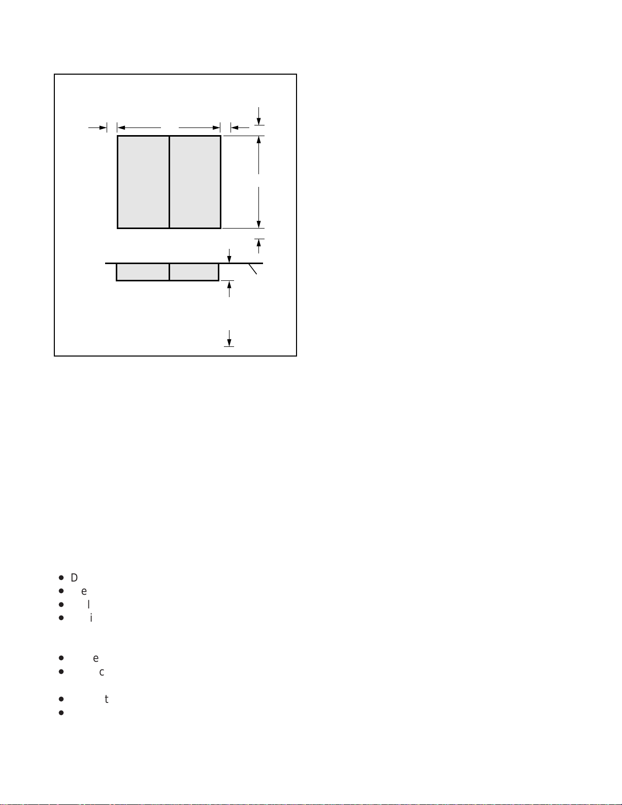
Figure 2-1 shows the minimum clearance requirements for the STRATA DK8 system, and includes
the recommended mounting location and clearance requirements for the optional HPFB. Figures
2-2 (Base Key Service Unit) and 2-3 (Base and
Expansion Key Service Unit together) show the
minimum clearance requirements for the standard
DK8 KEY SERVICE UNIT
AND HPFB CLEARANCE
FRONT VIEW
HPFB
DK 8 KSU
2" 2"10"
TOP VIEW
3"
3 FEET
2"
2"
16.4"
2"
WALL
DK16 BASE KEY SERVICE UNIT CLEARANCE
FRONT VIEW
2" 2"
TOP VIEW
12.25"
DK 16
BASE KSU
3.5"
3 FEET
2"
18"
2"
WALL
FIGURE 2-1
DK8 KEY SERVICE UNIT AND HPFB
MINIMUM CLEARANCE REQUIREMENTS
FIGURE 2-2
DK16 BASE KEY SERVICE UNIT
MINIMUM CLEARANCE REQUIREMENTS
2-1
Page 16
INSTALLATION-SITE REQUIREMENTS
SECTION 100-816-202
MARCH 1993
DK16 BASE AND EXPANSION
UNIT CLEARANCE
FRONT VIEW
2"
TOP VIEW
20"
BASEEXP
BASEEXP
2"
3.5"
3 FEET
2"
18"
2"
WALL
FIGURE 2-3
DK16 COMBINED BASE AND
EXPANSION KEY SERVICE UNIT
MINIMUM CLEARANCE REQUIREMENTS
and optioned STRATA DK16 system. Refer to
Chapter 4 for DK16 key service unit wall mounting
instructions.
3.03 If reserve power is to be installed for the
STRATA DK16, the batteries will require a wellventilated location close (within nine feet) to the
DKSUB16 (the optional Toshiba-supplied battery
cable is 9 feet in length). The STRATA DK8
reserve battery (HPFB) should be mounted directly above the DKSU8 as shown in Figure 2-1.
3.10 Electrical/Environmental Requirements
and Characteristics
3.11 The electrical/environmental requirements
and characteristics for each system are provided
in Table 2-A.
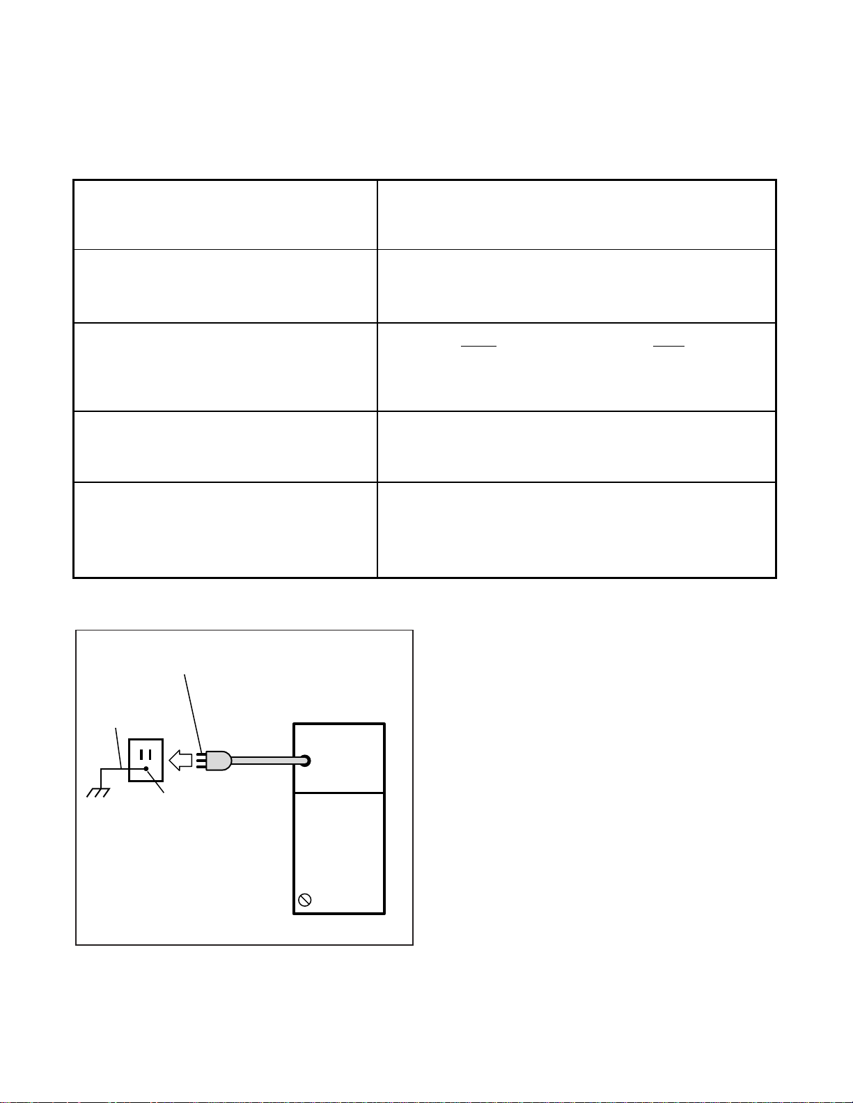
4 GROUNDING REQUIREMENTS
4.00 The systems require a solid earth ground for
proper operation. Failure to provide ground may
lead to confusing trouble symptoms and, in extreme cases, system failure. The AC power cord
contains a conductor for the "third wire ground"
provided by the commercial power outlet. The
third-wire ground should be the only ground necessary for the DK8/DK16; this ground must originate at the buildings main power distribution panel
and have a solid connection to earth ground.
(Figure 2-4)
4.10 Third Wire Ground Test
3.02 The following conditions must be considered
when selecting a location for the key service unit(s):
The location MUST BE:
•
Dry and clean
•
Well ventilated
•
Well illuminated
•
Easily accessible
The location MUST NOT BE:
•
Subject to extreme heat or cold
•
Subject to corrosive fumes, dust, or other air-
borne contaminants
•
Subject to excessive vibration
•
Next to television, radio, office automation, or
high frequency equipment
4.11 Test the "third wire ground" for continuity by
either measuring the resistance between the third
prong terminal (earth ground) and a metal cold
water pipe (maximum: 1 ohm), or by using a
commercially available earth ground indicator. If
neither procedure is possible, perform the following earth ground test procedure:
WARNING!
Hazardous voltages that may cause death
or injury are exposed during the following
test. Use great care when working with AC
power line voltage.
1) Obtain a suitable voltmeter, and set it for a
possible reading of up to 250 VAC.
2-2
Page 17
SUMMARY OF ELECTRICAL/ENVIRONMENTAL CHARACTERISTICS
GENERAL
Primary power
Input AC
AC frequency
Power
Environmental specifications
Operating temperature
Operating humidity
Storage temperature
Power supply
DC voltage output
specification
Battery charger characteristics
(DK16 only)
INSTALLATION-SITE REQUIREMENTS
SECTION 100-816-202
TABLE 2-A
85 ~ 135VAC
50/60 Hz
DK8-46 watts maximum, DK16-75 watts maximum
32 ~ 104°F (0 ~ 40°C)
20 ~ 80% relative humidity without condensation
- 4 ~ 158°F (-20 ~ 70°C)
DK16
–24VDC: (–26.3 ~ –27.8VDC)
+5VDC: ( +4.5 ~ +5.5VDC)
–5VDC: ( –4.5 ~ –5.5VDC)
Charger: current limiting
Nominal float voltage: 2.275 volts/cell
Charge current: 0.7 amps maximum
Battery discharge cut-off voltage: 20.5 ± 0.5VDC
DK8
+24VDC: (+26.3 ~ +27.8VDC)
+5VDC: ( +4.5 ~ +5.5VDC)
Note: +5V converter
on KSU PCB
MARCH 1993
QSTU, KSTU, PSTU or PESU (circuits 1 & 2)
Ring voltage
Ringing capability
GROUND 1 THIRD WIRE GROUND
TO AC POWER CORD
THIRD WIRE
AC GROUND
A
ELECTRICAL
SYSTEM GROUND
DK8 OR DK16 KSU
POWER
SUPPLY
FG
FIGURE 2-4
KSU GROUNDING DIAGRAM
Square wave output with high/low option jumper:
Low position, 130 ± 20VDC peak–to–peak (no-load)
High position, 190 ± 25VDC peak–to–peak (no-load)
Two ringers maximum per circuit, high or low position
2) Connect the meter probes between the two
main AC voltage terminals (white and black
wires) on the wall outlet. The reading obtained
should be between 100 ~ 120 VAC.
3) Move one of the meter probes to the third
terminal (green wire ground). Either the same
reading or a reading of zero volts should be
obtained.
4) If the reading is zero volts, leave one probe on
the ground terminal and move the other probe
to the second voltage terminal.
CAUTION!
If a reading of zero volts is obtained on
both voltage terminals (white wire to green
wire, black wire to green wire), the outlet is
not properly grounded. Omit steps 5 and
6, and proceed directly to step 7.
2-3
Page 18

INSTALLATION-SITE REQUIREMENTS
SECTION 100-816-202
MARCH 1993
5) If a reading of zero volts on one terminal, and
a reading of 100 ~ 120 VAC on the other
terminal is obtained, remove both probes from
the outlet.
6) Set the meter to the “OHMS/Rx1” scale. Place
one probe on the ground terminal, and the
other probe on the terminal that produced a
reading of zero volts. The reading should be
less than 1 ohm.
CAUTION!
If the reading is more than one ohm, then
the outlet is not adequately grounded.
7) If the above tests show the outlet is not properly grounded, the condition should be corrected (per Article 250 of the National Electrical Code) by a qualified electrician before the
system is connected.
4.20 Alternate or Additional Ground
4.21 If the “third wire” AC ground can not practi-
cally be improved or if extreme motor noise or
other disturbance causes system malfunction, or if
local area lightning storms exist, a separate direct
ground may be warranted.
4.22 Connect a separate earth ground from a cold
water pipe or earth grounding rod directly to the FG
screw terminal on the DK8/DK16 power supply.
See Figure 4-5 of Section 100-816-204 (for
STRATA DK8) or Figure 5-8 of Section 100-816-
205 (for STRATA DK16).
2-4
Page 19

TOSHIBA SYSTEM PRACTICES
DIGITAL KEY TELEPHONE SYSTEMS
INSTALLATION-CONFIGURATION
SECTION 100-816-203
MARCH 1993
INSTALLATION
CHAPTER THREE
SYSTEM CONFIGURATION
Page 20

Page 21

INSTALLATION-CONFIGURATION
SECTION 100-816-203
MARCH 1993
TABLE OF CONTENTS
PARAGRAPH SUBJECT PAGE
1 INTRODUCTION ...................................................................................................... 3-1
2 SYSTEM CAPACITY................................................................................................ 3-1
2.00 Total System Capacity.......................................................................................... 3-1
2.10 The DK8 Key Service Unit.................................................................................... 3-1
2.20 The DK16 Base Key Service Unit......................................................................... 3-1
2.30 The DK16 Expansion Key Service Unit................................................................ 3-1
3 STATION CONSIDERATIONS ................................................................................ 3-5
3.10 Telephone Circuit (Port) Types............................................................................. 3-5
3.20 Digital Telephone Circuit Connections ................................................................. 3-5
3.30 Electronic Telephone Circuit Connections (STRATA DK16 Only) ........................ 3-8
3.40 Standard Telephone Circuit Options .................................................................... 3-8
4 TELEPHONE UPGRADES ...................................................................................... 3-9
4.10 Digital Telephone Upgrades................................................................................. 3-9
4.20 Electronic Telephone Upgrades ........................................................................... 3-9
5 CONFIGURATION EXAMPLES............................................................................... 3-9
5.10 Strata DK8 - Example 1 (Small Retail Store)........................................................ 3-9
5.20 Strata DK8 - Example 2 (Home Office) ................................................................ 3-9
5.40 Strata DK16 - Example 1 (Bank) .......................................................................... 3-10
5.50 Strata DK16 - Example 2 (Office/Warehouse)...................................................... 3-10
6 CONFIGURATION WORKSHEET ........................................................................... 3-10
TABLE LIST
TABLE TITLE PAGE
3-A DK8 CO LINE/STATION CONFIGURATION GUIDE............................................... 3-2
3-B DK16 CO LINE/STATION CONFIGURATION GUIDE (BASE AND
EXPANSION UNIT).................................................................................................. 3-2
3-C DK8 KEY SERVICE UNIT COMPONENTS ............................................................. 3-3
3-D DK16 BASE KEY SERVICE UNIT COMPONENTS................................................. 3-4
3-E DK16 EXPANSION KEY SERVICE UNIT PCBs ...................................................... 3-5
3-F INTERFACE OPTION .............................................................................................. 3-6
3-G STRATA DK8 STATION APPARATUS OVERVIEW ............................................... 3-6
3-H STRATA DK16 STATION APPARATUS OVERVIEW ............................................. 3-7
WORKSHEETS
NUMBER TITLE PAGE
1 DK8 STATION AND CO LINE TOTALS................................................................... 3-11
2 DK8 KEY SERVICE UNIT AND PCBs ..................................................................... 3-12
3 DK8 PERIPHERALS AND UPGRADES .................................................................. 3-13
1 DK16 STATION AND CO LINE TOTALS................................................................. 3-15
2 DK16 KEY SERVICE UNIT AND PCBs ................................................................... 3-16
3 DK16 PERIPHERALS AND UPGRADES ................................................................ 3-17
4 DK16 SYSTEM POWER CHECK ............................................................................ 3-19
3-i
Page 22

INSTALLATION-CONFIGURATION
SECTION 100-816-203
MARCH 1993
3-ii
Page 23

INSTALLATION-CONFIGURATION
SECTION 100-816-203
MARCH 1993
1 INTRODUCTION
1.00 This chapter offers guidelines and consider-
ations on how to configure a STRATA DK8/DK16
system, which can support a wide variety of stations and peripherals.
2 SYSTEM CAPACITY
2.00 Total System Capacity
2.01 The STRATA DK8/DK16 systems have a
modular design which allows them to support a
number of station and CO line configurations. The
main component of each system is the Key Service Unit. The DK8 KSU can have up to 10 stations
and four CO lines. The DK16 Base Key Service
Unit can have up to 12 stations and four CO lines.
An Expansion Key Service Unit can be added to
the DK16 to increase the station capacity to 20 and
the CO line capacity to eight. Station and CO line
configurations are shown in Table 3-A (for DK8)
and Table 3-B (for DK16).
2.10 The DK8 Key Service Unit
2.11 Station and CO Lines. The DK8 Key Service
Unit comes standard with four digital telephone
circuits (ports) and two CO line circuits (Table
3-C). An optional printed circuit board called the
QCDU can be added to the KSU to provide one CO
line circuit and two digital telephone circuits. A
maximum of two QCDUs may be added to provide
a total of four additional digital telephone circuits
and two additional CO line circuits. Another optional printed circuit board called the QSTU can be
added to the DK8 KSU to provide two standard
telephone circuits.
2.12 Peripherals. The DK8 Key Service Unit can
support a number of peripherals, which are not
considered as stations and do not affect the maximum station and CO line capacities. A customersupplied Music-on-hold source, optional reserve
power battery and charger, a customer-supplied
emergency standard telephone for system power
failure occurrences and an amplifier with speaker
for paging and night ringing can all be connected
to the Key Service Unit (Table 3-C). A relay contact
is also provided to control one of the following
peripherals: Music-on-hold source, night bell, or
page amplifier mute control.
2.20 The DK16 Base Key Service Unit
2.21 Station and CO Lines. The DK16 Base Key
Service Unit comes standard with eight digital
telephone circuits (ports) and four CO line circuits
(Table 3-D). An optional printed circuit board called
the KSTU can be added to the unit to provide four
standard telephone circuits (ports).
2.22 Peripherals. The DK16 Base Key Service
Unit can support a number of peripherals, which
are not considered as stations and do not affect
the maximum station and CO line capacities. A
customer-supplied Music-on-hold source, customer-supplied separate background music
source, customer-supplied reserve power batteries, a customer-supplied emergency standard telephone for system power failure occurrences and an amplifier with speaker for paging
and night ringing can all be connected to the
Base Key Service Unit (Table 3-D). A relay
contact is also provided to control one of the
following peripherals: Music-on-hold source, night
bell, or Page Amplifier mute control.
2.30 The DK16 Expansion Key Service Unit
2.31 Station and CO Lines. The optional DK16
Expansion Key Service Unit has four universal
slots which can support a maximum of four CO
lines and eight stations. Printed circuit boards
(PCBs) that support CO lines and can be installed
in the Expansion Unit are the PCOU and KCDU
(Table 3-E). PCBs that can support stations and be
installed in the Expansion Unit are the PDKU,
PEKU, PSTU, PESU, and KCDU.
2.32 Peripherals. The Expansion Unit can support either a PIOU or PIOUS PCB, which both
provide, among other features, Station Message
Detail Recording (SMDR), an interface for a local
programming terminal, and connectors for an internal modem (IMDU) for remote maintenance
and administration (Table 3-F). Any device that
connects to the PIOU or PIOUS should not be
considered a station and does not affect the
system's station capacity.
3-1
Page 24
INSTALLATION-CONFIGURATION
SECTION 100-816-203
MARCH 1993
DK8 CO LINE/STATION CONFIGURATION GUIDE
TABLE 3-A
EQUIPMENT
KSU = Key Service Unit ·2 CO Lines/4 digital circuits)
QCDU = Optional PCB (1 CO line/2 digital circuits)
QSTU = Optional PCB (2 standard circuits)
CONFIGURATION CO
LINES BY STATION
2 by 4
2 by 6
3 by 6
3 by 8
4 by 8
4 by 10
COs DKTs SLTs EQUIPMENT
2
2
3
3
4
4
4
4
6
6
8
8
2
2
2
CO = Central Office
DKT = Digital Telephone
SLT = Standard Telephone
KSU
KSU + QSTU
KSU + QCDU
KSU + QCDU + QSTU
KSU + QCDU + QCDU
KSU + QCDU + QCDU + QSTU
TABLE 3-B
DK16 CO LINE/STATION CONFIGURATION GUIDE (BASE AND EXPANSION UNIT)
EQUIPMENT
BU
KSTU
EU
PDKU
KCDU
PEKU
PESU
Base Unit (4 CO lines/8 digital circuits)
=
Base Unit Option (4 standard circuits)
=
Expansion Unit
=
EU option (8 digital circuits)
=
EU option (2 CO lines/4 digital circuits)
=
EU option (8 electronic circuits)
=
EU option (2 standard/4 electronic circuits)
=
PSTU
PCOU
CO
DKT
EKT
SLT
EU option (8 standard circuits)
=
EU option (4 CO lines)
=
Central Office line
=
Digital telephone
=
Electronic telephone
=
Standard telephone
=
CONFIGURATION CO
LINES BY STATION
4 by 8
4 by 12
4 by 14
4 by 16
4 by 16
4 by 16
4 by 18
4 by 20
4 by 20
4 by 20
6 by 12
6 by 16
8 by 8
8 by 12
8 by 14
8 by 16
8 by 16
8 by 16
8 by 18
8 by 20
8 by 20
8 by 20
8 by 20
COs DKTs EKTs SLTs EQUIPMENT
4
4
4
4
4
4
4
4
4
4
6
6
8
8
8
8
8
8
8
8
8
8
8
16
16
12
12
16
16
16
16
8
8
8
8
8
8
8
8
8
8
8
8
8
8
8
4
8
4
8
4
8
4
8
4
2
8
6
4
4
12
4
4
2
6
4
4
4
12
BU
BU + KSTU
BU + EU + PESU
BU + EU + PSTU
BU + EU + PEKU
BU + EU + PDKU
BU + KSTU + PESU
BU + KSTU + EU + PEKU
BU + KSTU + EU + PDKU
BU + KSTU + EU + PSTU
BU + EU + KCDU
BU + KSTU + EU + KCDU
BU + EU + PCOU
BU + KSTU + EU + PCOU
BU + EU + PCOU + PESU
BU + EU + PCOU + PEKU
BU + EU + PDKU + PCOU
BU + EU + KCDU + KCDU
BU + KSTU + EU + PCOU + PESU
BU + KSTU + EU + KCDU + KCDU
BU + KSTU + EU + PCOU + PEKU
BU + KSTU + EU + PCOU + PDKU
BU + KSTU + EU + PCOU + PSTU
3-2
Page 25

Item Connector TypeSupports Standard Optional
Digital Telephone Circuits (4)
CO Line Circuits (2)
Power Failure Transfer Interface
Battery Backup Interface
Music-On-Hold/BGM Interface
600 Ohm page Interface
CO line CKT (1)/
Digital Telephone CKT (2) (QCDU)
(max. 2 QCDU per system)
Standard Telephone
Interface Unit (QSTU)
•
2 standard telephone circuits
•
(1 max.) QSTU per system
DTMF/ABR Tone Receiver
(3-Receiver CKT per QRCU )
Control Relay
Conference Circuit Interface Unit
(QCNU)
SMDR/TTY Interface Unit (QSMU)
(Requires PPTC)
TABLE 3-C
DK8 KEY SERVICE UNIT COMPONENTS
•
Digital Telephones (with
or without PDIU–DI2 or
ADM)
•
Stand-alone Data
Interface Units (PDIU-DS)
•
Door Phone Lock/Control
Unit (DDCB)
•
Loop Start CO Lines
•
Standard Telephone
(one)*
•
Optional HPFB Battery
(one or two per system)
•
Music-on-hold/BGM
Source*
•
Amplifier/Speaker
•
Digital Telephones (with
or without PDIU–DI2 or
ADM)
•
Stand-alone Data
Interface Units (PDIU-DS)
•
Loop Start CO Line
•
Standard Telephones*
•
Other Single-line Devices*
•
Fax Machine*
•
Voice Mail Devices
•
Alternate BGM source*
•
Automatic Busy Redial
•
Standard telephone ports
•
DISA
One of the following:
•
Night Relay
•
External Page Mute
•
MOH Control Relay
•
2 Simultaneous
Conferences
•
SMDR Printer*, or
•
Maintenance Terminal* or
•
Modem*
25-pair Amphenol
RJ11 Modular
RJ11 Modular
Proprietary
Cable/Connector
RCA Jack
RCA Jack
25-pair Amphenol
RJ11 Modular
25-pair Amphenol
Internal
25-pair Amphenol
Internal
6-pin Modular
(PPTC adaptor)
INSTALLATION-CONFIGURATION
SECTION 100-816-203
MARCH 1993
✓
✓
✓
Interface
HPFB
with cable
✓
✓
✓
✓
✓
✓
✓
✓
Customer supplied equipment not offered by Toshiba Telecommunication Systems Division.
*
3-3
Page 26
INSTALLATION-CONFIGURATION
SECTION 100-816-203
MARCH 1993
TABLE 3-D
DK16 BASE KEY SERVICE UNIT COMPONENTS
Item
Digital Telephone Circuits (8)
CO Line Circuits (4)
Power Failure Transfer Interface
Battery Backup Interface with
built-in charger
Music-On-Hold/BGM Interface
600 Ohm page Interface
Standard Telephone
Interface Unit (4-Circuit)
(KSTU)
*
Supports
Digital Telephones (with
•
or without PDIU–DI2 or
ADM)
Stand-alone Data
•
Interface Units (PDIU-DS)
Door Phone Lock/Control
•
Unit (DDCB)
Digital Direct Station
•
Selection Console (DDSS)
Loop Start CO Lines
Standard Telephone (one)
Two 12-volt Batteries
Music-on-Hold/BGM source
Amplifier/Speaker
Standard Telephones
•
Other Single-line Devices
•
Alternate BGM Source
•
Fax machine
•
Voice mail devices
•
*
*
*
*
Connector Type
25-pair Amphenol
RJ11 Modular
RJ11 Modular
*
Proprietary
Connector/Cable
RCA Jack
*
RCA Jack
25-pair Amphenol
*
Standard Optional
✓
✓
✓
✓
Cable and
Batteries
✓
✓
✓
Automatic Busy Redial
DTMF/ABR
Receiver (K4RCU)
Feature Cartridge
Control Relay
Customer supplied equipment not offered by Toshiba Telecommunication Systems Division.
*
•
Standard Telephone Ports
•
Interprets DTMF Tones
•
DISA
•
Future Feature Upgrades
•
Choice of one:
MOH Source Control
•
Night Bell Control
•
BGM Mute Control
•
Internal
Internal
25-pair Amphenol
3-4
✓
✓
✓
Page 27

TABLE 3-E
DK16 EXPANSION KEY SERVICE UNIT PCBs
INSTALLATION-CONFIGURATION
SECTION 100-816-203
MARCH 1993
PCB
PDKU
PEKU
PSTU
PESU
PCOU
Circuits per PCB
8 digital telephone
circuits
8 electronic telephone
circuits
8 standard telephone
circuits
2 standard telephone/
4 electronic telephone circuits
(standard/electronic
telephone ports)
4 CO line circuits
(lines)
Interfaces
• Digital telephones with or
without PDIU-DI2 or ADM
• DDSS console
• PDIU-DSs
• DDCB
• Electronic telephones
• HDSS console
• BGM source
• EOCU PCB for OCA
• Standard telephones
• Voice mail ports
• Background music source
• Off-premises stations
• Other similar devices
Standard: same as PSTU
Electronic: same as PEKU
except PESU does not
support HDSS console
• Central Office loop start
lines
Connector
25-pair amphenol
25-pair amphenol
25-pair amphenol
25-pair amphenol
RJ14C modular
KCDU
PIOU,
PIOUS
2 CO line circuits/
4 digital telephone circuits
See Table 3-D
• Central Office loop
• DKT circuits same as
See Table 3-D
3 STATION CONSIDERATIONS
3.00 For configuration purposes, a station can be
considered as any device which is connected to a
dedicated telephone circuit. Although the words
"telephone" and "station" are often used synonymously and interchangeably in STRATA DK8/
DK16 documentation, devices other than telephones—such as Stand-alone Data Interface units
(PDIU-DSs)—should also be considered as stations when configuring a system, because they
require a dedicated telephone circuit. A station
apparatus overview is shown in Table 3-G (for
STRATA DK8) and Table 3-H (for STRATA DK16).
RJ14C Modular
start lines
PDKU, except no DDSS
(CO Line circuits)
25-pair amphenol
(digital telephone circuits)
25-pair amphenol (PIOU)
Spring clip terminal (PIOUS)
3.10 Telephone Circuit (Port) Types
3.11 There are three types of telephone circuits to
which stations can be connected: digital telephone
circuits, electronic telephone circuits, and standard telephone circuits. All three types of circuits
are available with the STRATA DK16. The STRATA
DK8 does not support electronic telephone circuits.
3.20 Digital Telephone Circuit Connections
3.21 The STRATA DK8 Key Service Unit provides
four digital telephone circuits. The QCDU PCB
provides two.
3-5
Page 28
INSTALLATION-CONFIGURATION
SECTION 100-816-203
MARCH 1993
Expansion Unit Interface Options PIOU PIOUS
TABLE 3-F
PIOU/PIOUS INTERFACE OPTION (DK16 ONLY)
Zone Page Interface (unamplified, 4 zones)
Night Transfer or Music-on-Hold Control Relay
Door Lock or External Amplifier Control Relay
Alarm Sensor
SMDR output (RS-232/6-wire modular connector)
Maintenance Port for a Local ASCII Terminal or
External Modem (RS-232/6-wire modular connector)
Remote Maintenance Modem (IMDU subassembly, no
external connector)
NOTE: X = the option is provided
Station
Digital Telephone
DKT with or without
ADM or PDIUDI
Stand-alone Data
Interface Unit (PDIUDS)
Digital Door
Phone/Lock Control
Unit (DDCB)
Single-wire pair
devices:
•
Standard
Telephone
•
Voice Mail Device
•
Facsimile Machine
•
Modem
•
Dictation
Equipment
Alternate
Background Music
Source
*
TABLE 3-G
STRATA DK8 STATION APPARATUS OVERVIEW
Type and Number of
Circuits Required
Digital, one for each
DKT
Digital, one for each
PDIU-DS
Digital, one for each
DDCB
Standard, one for
each device (voice
mail devices may
require more than one
circuit)
Standard port for the
source
PCB or Interface
KSU (Circuits 1 ~ 4)
QCDU (Circuits 1 ~ 2)
KSU (Circiuts 1 ~ 4)
QCDU (Circuits 1 ~ 2)
KSU Port 02
Port 03
QSTU (Circuits 1 ~ 2)
QSTU (Circuit 2)
Port 19
X
X
X
X
X
X
X
KSU
Capacity
4
4
2
—
1
X
X
X
X
X
X
KSU and Optional PCB
Combined Capacity
8
8
2
2
1
*
May require interface transformer, see Section 100-816-207.
3-6
Page 29

INSTALLATION-CONFIGURATION
TABLE 3-H
STRATA DK16 STATION APPARATUS OVERVIEW
SECTION 100-816-203
MARCH 1993
Station
Digital Telephone
(DKT with or without
ADM or PDIU-DI)
Stand-alone Data
Interface Unit
(PDIU-DS)
Digital Direct Station
Selection Console
(DDSS)
Digital Door
Phone/Lock Control
Unit (DDCB)
Electronic Telephone
(EKT)
Electronic Direct
Station Selection
Console (HDSS)
Conference Amplifier
Single-wire-pair
Devices:
• Standard Telephone
• Voice Mail Device
• Facsimile Machine
• Modem
• Dictation Equipment
Alternate
Background Music
Source
Type and Number of
Circuits Required
Digital, one for each
DKT
Digital, one for each
PDIU-DS
Digital, one for each
DDSS
Digital, one for each
DDCB
Electronic, one for
each EKT
Electronic, two for the
HDSS
Electronic, two for the
amplifier
Standard, one for
each device (voice
mail devices may
require more than one
circuit)
Standard or
Electronic, one for the
source
PCB or Interface
Base Unit (Circuits 1~8)
PDKU2 (Circuits 1~8)
KCDU (Circuits 1~4)
Base Unit (Circuits 1~8)
PDKU2 (Circuits 1~8)
KCDU (Circuits 1~4)
Base Unit (Circuit 8)
PDKU (Circuit 8)
Base Unit (Circuit 5)
PDKU (Circuit 1)
or first
KCDU (Circuit 1)
PEKU (Circuits 1~8)
PESU (Circuit 5~8)
PEKU (Circuits 7 and 8)
PEKU (Circuits 6 and 7)
PESU (Circuits 6 and 7)
KSTU (Circuits 1~4)
PSTU (Circuits 1~8)
PESU (Circuits 1~2)
KSTU (Circuit 4)
PEKU (Circuit 3)
PESU (Circuit 8)
PSTU (Circuit 4)
Base Unit
Capacity
8
8
1
1
0
0
0
4
1
Base and Expansion
Unit Combined Capacity
16
16
2
2
8
1
1
12
1
*
May require interface transformer, see Section 100-816-207.
3-7
Page 30

INSTALLATION-CONFIGURATION
SECTION 100-816-203
MARCH 1993
NOTE:
A maximum of two QCDU PCBs may be
installed in the STRATA DK8.
3.22 The STRATA DK16 Base Key Service Unit
and the PDKU PCB each provide eight digital
telephone circuits. The KCDU PCB provides four.
NOTE:
A maximum of two KCDU PCBs may be
installed in the STRATA DK16. If a KCDU is
installed, no other type of station PCB can be
installed in the STRATA DK16.
3.23 The following devices can be connected to
digital telephone circuits:
•
Digital Telephones (2000- and 1000-series):
Each digital telephone requires one circuit, and
each digital telephone circuit can support a
digital telephone.
•
Stand-alone Data Interface Units (PDIU-DS):
Each PDIU-DS requires one circuit. Any digital
telephone circuit, except for Circuit 8 on a PDKU1
(STRATA DK16), can support a PDIU-DS (see
Note 1).
NOTES:
1. There are two versions of the PDKU:
PDKU1 and PDKU2. The versions are
identical, except that Circuits 1 ~ 8 on the
PDKU2 can each support PDIU-DSs/
PDIU-DI, while only Circuits 1 ~ 7 on a
PDKU1 can support PDIU-DSs or PDIUDIs. Also, PDIU1 does not support 2000series digital telephone continuous DTMF
tones.
2. The Integrated Data Interface Unit (PDIUDI/PDIU-DI2) and the Add-on Module
(ADM) do not require a dedicated circuit.
They share a circuit with the telephone.
3. Only one option (PDIU-DI2 or ADM) can
be installed on a 2000-series digital telephone.
• Digital Direct Station Selection Console
(DDSS): (available with STRATA DK16 only)
Each DDSS Console requires one circuit. DDSS
Consoles can connect only to Circuit 8 in the
Base Key Service Unit and Circuit 8 on a PDKU.
The KCDU cannot support a DDSS console.
• Digital Door Phone/Lock Control Box
(DDCB): Each DDCB requires one circuit.
DDCBs can only connect to Circuits 3 and 4
(Ports 02 and 03) in the STRATA DK8 Key
Service Unit or Circuit 5 (Port 04) in the STRATA
DK16 Base Key Service Unit, and Circuit 1 (Port
12) on either the PDKU or KCDU (STRATA
DK16).
3.30 Electronic Telephone Circuit Connec-
tions (STRATA DK16 Only)
3.31 There are no electronic telephone circuits in
the Base Key Service Unit, and none can be
added to it. However, either the PEKU PCB, which
has eight electronic telephone circuits, or the
PESU, which has four electronic telephone circuits, can be installed in the Expansion Key Service Unit. The following devices can be connected
to electronic telephone circuits.
•
Electronic Telephones (6500-, 6000-, 3000-,
2000-series): An electronic telephone can be
connected to any electronic telephone circuit.
One electronic telephone circuit is required per
electronic telephone.
• Electronic Direct Station Selection Console
(HDSS): The system will support only one HDSS
console. The console must be connected to
both Circuits 7 and 8 on the PEKU. The PESU
will not support an HDSS Console.
• Alternate Background Music Source: The
system will support an alternate Background
Music source which can be heard over digital
and electronic telephone speakers and external
page speakers. This source can be connected
to either Circuit 3 on a PEKU, Circuit 8 on a
PESU, or Circuit 4 on a KSTU or PSTU PCB.
• Conference Amplifier: An amplifier for two CO
line conferencing can be connected to Circuits
6 and 7 (Ports 17 and 18) on a PEKU or PESU.
3.40 Standard Telephone Circuit Options
3.41 In addition to supporting standard telephones,
each of the standard telephone circuits can support any one of a number of single-wire-pair devices, including voice mail/Auto Attendant devices
and modems. The QSTU, which can be installed
in the STRATA DK8 Key Service Unit, has two
3-8
Page 31

INSTALLATION-CONFIGURATION
SECTION 100-816-203
MARCH 1993
standard telephone circuits. The KSTU, which can
be installed in the STRATA DK16 Base Key Service Unit, has four standard telephone circuits; the
PSTU, which can be installed in the DK16 Expansion Key Service Unit, has eight; and the PESU,
which can also be installed in the DK16 Expansion
Unit, has two (Circuits 1 and 2).
4 TELEPHONE UPGRADES
4.00 Digital and Electronic telephones can be
upgraded for a number of features; there are no
upgrades for standard telephones. Each of these
upgrades shares a circuit with the telephone that it
is connected to and is not considered a station.
4.10 Digital Telephone Upgrades
4.11 Digital telephones can be upgraded with the
following subassemblies:
• Integrated Data Interface Unit (PDIU-DI/PDIU-
DI2): A Digital telephone can be upgraded with
a PDIU-DI/PDIU-DI2 to provide the telephone
with data switching capabilities. 2000-series
Digital Telephones use the PDIU-DI2, and 1000series Digital Telephones use the PDIU-DI.
PDIU-DI2 cannot be installed on a telephone if
ADM is installed.
• Add-on Module (ADM): A 2000-series Digital
Telephone can be upgraded with an ADM to
provide 20 Direct Station Selection buttons on
STRATA DK16, or 10 DSS buttons, 8 speed dial
buttons, one night transfer button and one all
call page button on STRATA DK8. The 1000series Digital Telephone models cannot support
ADMs. ADM cannot be installed on a telephone
if PDIU-DI2 is installed.
• Off-hook Call Announce Upgrade (DVSU): A
Digital telephone that must receive Off-hook
Call Announce must be upgraded with a DVSU.
• Loud Ringing Bell/Headset Upgrade (HHEU):
A digital telephone can be upgraded with an
HHEU to provide a dual interface for the Loud
Ringing Bell feature and/or a headset. (Simultaneously with PDIU-DI2 or ADM).
4.20 Electronic Telephone Upgrades
4.21 On STRATA DK16, electronic telephones
can be upgraded with the following subassemblies:
• Off-hook Call Announce Upgrade (HVSU2 or
HVSU/HVSI): An electronic telephone must be
upgraded with the HVSU2 subassembly or the
combined HVSU/HVSI subassemblies to receive Off-hook Call Announce.
NOTE:
A PEKU or PESU PCB that supports electronic telephones that must receive Off-hook
Call Announce must be equipped with an
EOCU.
• Loud Ringing Bell/Headset Upgrade (HHEU):
An electronic telephone can be upgraded with
an HHEU to provide a dual interface for the Loud
Ringing Bell feature and a headset simultaneously.
5 CONFIGURATION EXAMPLES
5.00 The following provides an examples of how to
configure a STRATA DK8.
5.10 Strata DK8 - Example 1 (Smalll Retail
Store)
5.11 Customer Requirements. A store needs
two CO lines and four digital telephones.
5.12 Analysis. The store's system hardware re-
quirements are as follows:
• Two CO line circuits for the CO lines.
• Four digital telephone circuits for the digital
telephones.
5.13 Conclusion. A standard Key Service Unit
would be adequate in this case. The unit's standard four digital telephone circuits and two CO line
circuits could easily accommodate the store's needs
and allow for future expansion.
5.20 Strata DK8 - Example 2 (Home/Office)
5.21 Customer Requirements. In addition to three
CO lines, a home/office needs five digital telephones (three of which will have PDIU-DIs), a
modem, a door phone, one facsimilie machine,
Music-on-hold and Telephone Set Background
Music.
5.22 Analysis. The customer's requirements could
be broken down as follows:
3-9
Page 32

INSTALLATION-CONFIGURATION
SECTION 100-816-203
MARCH 1993
•
3 CO line circuits for the three CO lines
•
7 digital telephone circuits
§
one for each of the five digital telephones;
the PDIU-DIs do not require dedicated circuits.
§
one for a digital door phone/lock control unit
to support a door phone
§
one for the PDIU-DS connected to the modem
•
2 standard telephone circuits
§
one for the modem
§
one for the facsimilie machine
•
A music source for Music-on-hold and Background music can be connected to the Key
Service Unit MOH RCA jacks.
5.23 Conclusion. Several optional PCBs in addition to the Key Service unit would be needed for the
application. Two CO line circuits and four digital
telephone circuits would be provided by the KSU.
The third CO line circuit, as well as two digital
telephone circuits would be provided by an optional QCDU. A second QCDU would be necessary to provide the seventh digital telephone circuit. An optional QSTU would provide the two
standard telephone circuits. An optional QRCU
would be needed for the Dual-tone Multi-frequency
(DTMF) tones generated by the devices (modem
and facsimilie machine) connected to the standard
telephone lines.
5.30 The following provides an examples of how to
configure a STRATA DK16.
5.40 Strata DK16 - Example 1 (Bank)
5.41 Customer Requirements. A bank needs two
CO lines and six digital telephones (three of which
must be equipped with a PDIU-DI). It also wants to
connect a printer to a PDIU-DS.
5.42 Analysis. The bank's system hardware requirements are as follows:
• Two CO line circuits for the two CO lines.
• Seven digital telephone circuits. Six for telephones and one for the PDIU-DS. (The
PDIU-DIs do not require a dedicated circuit.)
5.50 Strata DK16 - Example 2 (Office/Warehouse)
5.51 Customer Requirements. In addition to five
CO lines, a small office-warehouse facility needs
11 digital telephones (three of which will have
PDIU-DIs), two PDIU-DSs, a modem, a facsimile
machine, conference capability, a door phone,
one standard telephone, Music-on-hold, and an
amplifier/speaker for paging.
5.52 Analysis. The customer's requirements could
be broken down as follows:
•
14 digital telephone circuits
§
one for each of the 11 digital telephones; the
PDIU-DIs do not require dedicated circuits.
§
one for each of the two PDIU-DSs
§
one for a digital door phone/lock control unit
to support a door phone
•
3 standard telephone circuits
§
one for the modem
§
one for the facsimile machine
§
one for the standard telephone
•
A music source for Music-on-hold and an amplifier/speaker for paging could both be connected
to the Key Service Unit RCA jacks.
•
A K4RCU would be needed for the Dual-tone
Multi-frequency (DTMF) tones generated by the
devices connected to the standard telephone
circuits.
•
A PCOU would be needed for the fifth CO line.
5.53 Conclusion. An Expansion Key Service Unit
in addition to the Base Key Service Unit would be
needed for this application. The three standard
telephone circuits could be contained on the optional KSTU PCB in the Base Unit. However, a
PDKU installed in the Expansion Unit would be
required for six of the 14 digital telephone circuits.
The Expansion Unit would also be needed for the
PCOU. The optional K4RCU, along with the music
source and the page/amplifier, as noted earlier,
could be connected to the Base Unit.
6 CONFIGURATION WORKSHEETS
5.43 Conclusion. A standard Base Key Service
Unit would be adequate in this case. The unit's
standard eight digital telephone circuits and four
CO line circuits could easily accommodate the
bank's needs.
6.00 Worksheets are provided in this chapter to
help configure the system.
3-10
Page 33

INSTALLATION-CONFIGURATION
SECTION 100-816-203
DK8 WORKSHEET 1, STATION AND CO LINE TOTALS
1. DIGITAL PORTS (CIRCUITS)
Device Quantity x Ports/Per = Ports Used
DDCBs (2 max.) _____ X 1 = ___________
PDIU-DSs (8 max.) _____ X 1 = __________
Digital Telephones (with or _____ X 1 = __________
without PDIU-DIs or ADMs)
(8 max.)
Total Digital Ports = __________
(8 max.)
2. STANDARD PORTS (CIRCUITS)
Device Quantity x Ports/Per = Ports Used
MARCH 1993
Maximum of 2 items
total, including Standard
Telephones:
Standard Telephones _____ X 1 = __________
or
Other Devices:
–Voice Mail
–Auto Attendant
–BGM Source
–Fax
–Modem _____ X 1 = __________
Total Standard Ports = __________
(2 maximum)
3. CO LINES
Number of CO lines required? _______
(Maximum of 4)
3-11
Page 34

INSTALLATION-CONFIGURATION
SECTION 100-816-203
MARCH 1993
DK8 WORKSHEET 2, KEY SERVICE UNIT AND PCBs
1. From Worksheet 1 enter the number of required ports (circuits) and lines.
Digital Ports: _____ (8 max)
Standard Ports: _____ (2 max)
CO Lines: _____ (4 max)
NOTE: The maximum number of digital ports is 8, and standard ports is 2. The
maximum number of CO lines is four.
2. Cross off the printed circuit boards (PCBs)—in addition to the standard Base Key Service Unit lines and
ports— needed to support the ports and lines entered in Step 1 of this worksheet.
KSU Interfaces (built-in)
2 CO lines, 4 digital ports
KSU Optional Unit Station and Line PCBs
QCDU (1 CO line and
2 digital ports): _____ two max.
QSTU (2 standard ports): _____ one max.
3. Refer to Worksheet 3 to determine option and peripheral requirements.
3-12
Page 35

INSTALLATION-CONFIGURATION
SECTION 100-816-203
MARCH 1993
DK8 WORKSHEET 3, PERIPHERALS AND UPGRADES
1. BASE UNIT PERIPHERALS
Battery Backup Interface: Yes or No _____
One or two HPFB batteries can be connected to a backup battery interface (Standard on DK8) to provide
backup battery backup if there is a power failure. (Connecting cable is included. 1-HPFB for .5 ~ 1 hour
backup; 2-HPFBs for 1.5 ~ 2 hours backup.)
QRCU: Yes or No _____
The QRCU is required to interpret Dual-tone Multi-frequency (DTMF) tones from standard telephones, Voice
Mail, Auto Attendant, and DISA CO circuits, or if the Auto Busy Redial (ABR) feature is required.
Music-on-hold/Background Music Source Interface: Yes or No _____
A music source can be connected to this interface (Standard on DK8) to provide Music-on-hold to CO lines
and stations on hold, and to provide Background Music to station speakers and external page speakers.
Power Failure Transfer Interface: Yes or No _____
A standard telephone can be connected to this interface to provide connection to a CO line if there is a power
failure. PFT interface is standard on DK8; one customer-supplied standard telephone is required.
600 ohm page Interface (Standard on DK8): Yes or No _____
This interface connects with customer-supplied speakers and amplifiers for paging (or Toshiba HESB) and
Background Music applications.
QSMU: Yes or No _____
A customer-supplied Station Message Detail Recording (SMDR) printer, or Remote Maintenance Terminal
(TTY) or modem.
PPTC: Yes or No _____
Modular adaptor required for interface to SMDR device or Maintenance Terminal or Modem.
2. TELEPHONE UPGRADES (All upgrades share the telephone port and do not require separate ports.)
Add-on Module (ADM): Total _____
2000-series digital telephones can be equipped with an Add-on Module to provide 10 Direct Station Selection
buttons, autodial buttons, all call page, and night transfer (if PDIU-DI2 is installed, ADM cannot be installed).
DVSU: Total _____
One DVSU is required for each digital telephone that must receive Off-hook Call Announce.
HESC-65A: Total _____
One HESC-65A modular connecting cable is required to connect the HESB to the HHEU in each telephone
requiring the Loud Ringing Bell feature. See HHEU and HESB.
HHEU: Total _____
One HHEU must be installed in each digital telephone that supports a headset or connects to an HESB for
the Loud Ringing Bell feature. See HESC-65A.
PDIU-DI2: Total_____ for 2000-series Digital Telephones;
(If ADM is installed, PDIU-DI2 cannot be installed).
PDIU-D1: Total_____ for 1000-series Digital Telephones
Digital telephones must be equipped with a PDIU-DI2 or a PDIU-DI to transmit and receive voice and data
calls.
3-13
Page 36

INSTALLATION-CONFIGURATION
SECTION 100-816-203
MARCH 1993
DK8 WORKSHEET 3, PERIPHERALS AND UPGRADES (continued)
Miscellaneous Peripherals
HESB (Amplifier/Speaker): Total _____
1. One HESB and HHEU is required for each digital telephone with the Loud Ringing Bell feature.
2. One HESB is optional to provide single-zone external page connected to the KSU's 600 ohm external
page output. (Customer-supplied amplifiers/speakers may be used in place of the HESB.)
3. One HESB is optional to provide a talkback amplifier/page speaker connected to the KSU's 600 ohm
external page output. (Customer-supplied amplifiers/speakers may be used in place of the HESB.) Talkback
requires MDFB also.
DDCB/MDFB (Door Phone): Total DDCBs _____ Total MDFBs _____
The MDFB plugs into the DDCB to provide a door phone. Each DDCB can support up to three MDFBs; a
maximum of two DDCBs and 6 MDFBs can be connected to the system. Each DDCB requires a digital
telephone circuit. The MDFB may also be connected to the HESB amplifier/speaker to provide page
talkback.
NOTE:
Worksheet 4, System Power Check, is not required for DK8. The DK8 power supply will support any DK8
maximum configuration.
3-14
Page 37

INSTALLATION-CONFIGURATION
SECTION 100-816-203
DK16 WORKSHEET 1, STATION AND CO LINE TOTALS
1. DIGITAL PORTS (CIRCUITS)
Device Quantity x Ports/Per = Ports Used
DDSS Consoles (2 max.) _____ X 1 = __________
DDCBs (2 max.) _____ X 1 = __________
PDIU-DSs (16 max.) _____ X 1 = __________
Digital Telephones (with or _____ X 1 = __________
without PDIU-DIs or ADMs)
(16 max. Total Digital Ports = __________
(16 max.)
2. ELECTRONIC PORTS (CIRCUITS)
Device Quantity x Ports/Per = Ports Used
HDSS Console (1 max.) _____ X 2 = __________
Alternate BGM Source (1 max.) _____ X 1 = __________
Conference Amplifier (1 max.) _____ X 2 = __________
Electronic Telephones _____ X 1 = __________
(8 max.)
MARCH 1993
Total Electronic Ports = __________
(8 max.)
3. STANDARD PORTS (CIRCUITS)
Device Quantity x Ports/Per = Ports Used
Maximum of 12 items
total, including Standard
Telephones:
Standard Telephones _____ X 1 = __________
or
Other Devices:
–Voice Mail _____ X 1 = __________
–Auto Attendant _____ X 1 = __________
–Fax _____ X 1 = __________
–Modem _____ X 1 = __________
–Alternate Background
Music (BGM) Source _____ X 1 = __________
Total Standard Ports = __________
(12 maximum)
4. CO LINES
Number of CO lines required? _______
(8 maximum)
3-15
Page 38

INSTALLATION-CONFIGURATION
SECTION 100-816-203
MARCH 1993
DK16 WORKSHEET 2, KEY SERVICE UNIT AND PCBs
1. From Worksheet 1 enter the number of required ports (circuits) and lines.
Digital Ports: _____
Electronic Ports: _____
Standard Ports: _____
CO Lines: _____
NOTE: The maximum number of combined digital, electronic, and standard ports
is 20. The maximum number of CO lines is eight.
2. Cross off the printed circuit boards (PCBs)—in addition to the standard Base Key Service Unit lines and
ports— needed to support the ports and lines entered in Step 1 of this worksheet.
Base Unit Interfaces/PCBs
Base Unit (4 CO lines, 8 digital ports): X built-in
KSTU (4 standard ports): _____ one max.
Expansion Unit Station and line PCBs
KCDU (2 CO lines and
4 digital ports): _____ two max. (KCDU cannot be installed
with any other type of
- or - station PCB or PCOU PCB)
PDKU (8 digital ports): _____ one max.
- or -
PEKU (8 electronic ports): _____ one max.
- or -
PSTU (8 standard ports): _____ one max.
- or PESU (2 standard ports and
(4 electronic ports): _____ one max.
PCOU (4 CO lines): _____ one max. (PCOU can be installed with
PDKU, PEKU, PESU, or
PSTU, but not with KCDU)
NOTES:
1. The Base Unit by can only support up to 12 stations (8 digital and 4 standard)
and four CO lines.
2. The Expansion Unit can support up to eight stations and four CO lines.
3. If installing two DDCBs, a PDKU or a KCDU is required to support the second
DDCB—no matter what the total number of digital ports.
4. If installing two DDSS Consoles, a PDKU is required to support the second
DDSS Console—no matter the total number of digital ports. (KCDU does not
support DDSS.)
3. Refer to Worksheet 3 to determine option and peripheral requirements.
4. Refer to Worksheet 4 to determine the amount of power used by the system.
3-16
Page 39

INSTALLATION-CONFIGURATION
SECTION 100-816-203
MARCH 1993
DK16 WORKSHEET 3, PERIPHERALS AND UPGRADES
1. BASE UNIT PERIPHERALS
Battery Backup Interface: Yes or No _____
Two 12-volt customer-supplied batteries can be connected to this interface to provide backup battery backup
if there is a power failure. See PBTC-3M.
K4RCU: Yes or No _____
The K4RCU is required to interpret Dual-tone Multi-frequency (DTMF) tones from standard telephones, Voice
Mail, Auto Attendant, and DISA CO circuits.
Music-on-hold/Background Music Source Interface: Yes or No _____
A music source can be connected to this interface (Standard on DK16) to provide Music-on-hold to CO lines
and stations on hold, and to provide Background Music to station speakers and external page speakers.
Alternate Background Music Source: Yes or No _____ (see Worksheet 1)
Power Failure Transfer Interface: Yes or No _____
A standard telephone can be connected to this interface to provide connection to a CO line if there is a power
failure. PFT interface is standard on DK16; one customer-supplied standard telephone is required.
PBTC-3M: Yes or No _____
One PBTC-3M cable is required for each system that requires battery backup. See Battery Backup Interface.
600 ohm page interface (Standard on DK16): Yes or No _____
This interface connects with customer-supplied speakers and amplifiers (or Toshiba HESB) for paging and
Background Music applications.
Night Bell: Yes or No _____
A customer supplied night ringing bell can be installed and controlled by the Base Unit relay control (Standard
on DK16).
2. EXPANSION UNIT PERIPHERAL PCB
PIOU or PIOUS: If yes, which one _____
See Table 3-D.
PPTC: One or Two _____
Modular adaptor, required for PIOU/PIOUS interface to SMDR device or local maintenance terminal.
3. TELEPHONE UPGRADES (All upgrades share the telephone port and do not require separate ports.)
Add-on Module: Total _____
2000-series digital telephones can be equipped with an Add-on Module to provide 20 Direct Station Selection
buttons. (If PDIU-DI2 is installed, Add-on Module cannot be installed.)
DVSU: Total _____
One DVSU is required for each digital telephone that must receive Off-hook Call Announce.
HESC-65A: Total _____
One HESC-65A modular connecting cable is required to connect the HESB to the HHEU in each telephone
requiring the Loud Ringing Bell feature. See HHEU and HESB.
3-17
Page 40

INSTALLATION-CONFIGURATION
SECTION 100-816-203
MARCH 1993
DK16 WORKSHEET 3, PERIPHERALS AND UPGRADES (continued)
HHEU: Total _____
One HHEU must be installed in each digital and electronic telephone that supports a headset or connects to
an HESB for the Loud Ringing Bell feature. See HESC-65A.
HVSU2 or Combined HVSU/HVSI: Total _____
Electronic telephones must be equipped with either the HVSU2 assembly or the combined HVSU and HVSIs
assemblies to receive Off-hook Call Announce. See EOCU under Miscellaneous Peripherals.
PDIU-DI2: Total_____ for 2000-series Digital Telephones;
PDIU-D1: Total_____ for 1000-series Digital Telephones
Digital telephones must be equipped with a PDIU-DI2 or a PDIU-DI to transmit and receive voice and data
calls. (If Add-on module is installed, then PDIU-DI2 cannot be installed.)
Miscellaneous Peripherals
DPFT: Yes or No_____
The DPFT provides a means to connect eight selected CO lines to standard telephones if there is a power
failure. (PSTU must be installed in Expansion Unit)
EOCU: Yes or No _____
An EOCU must be installed on a PEKU or PESU that is connected to electronic telephones which are
equipped to receive Off-hook Call Announce. See HVSU2 and HVSU/HVSI in Telephone Upgrades.
HESB (Amplifier/Speaker): Total _____
1. One HESB and HHEU is required for each digital and electronic telephone with the Loud Ringing Bell
feature.
2. One HESB is optional to provide single-zone external page connected to the Base Unit's 600 ohm external page output. (Customer-supplied amplifiers/speakers may be used in place of the HESB.)
3. One HESB is optional to provide a talkback amplifier/page speaker connected to the Base Unit's 600 ohm
external page output. (Customer-supplied amplifiers/speakers may be used in place of the HESB.) Talkback
for HESB requires an MDFB.
MDFB (Door Phone): Total _____
The MDFB plugs into the DDCB to provide a door phone. Each DDCB can support up to three MDFBs; a
maximum of two DDCBs can be connected to the system. Each DDCB requires a Digital Telephone circuit.
The MDFB may also be connected to the HESB amplifier/speaker to provide page talkback.
3-18
Page 41

INSTALLATION-CONFIGURATION
DK16 WORKSHEET 4, SYSTEM POWER CHECK
Total Power Used:
SECTION 100-816-203
MARCH 1993
Equipment Type:
2000- and 1000-series digital telephone
2000-series electronic telephone
3000-series electronic telephone
6000-series electronic telephone
6005-series electronic telephone
6500-series electronic telephone
DDSS/HDSS console*
PDIU-DI2 and PDIU-DI
PDIU-DS
Standard telephone
Add-on Module
* All series.
Equipment
Quantity
Power Used
X
(Factor)
X
X
X
X
X
X
X
X
X
X
X
Total Power Used
(1.0)
(2.0)
(2.5)
(2.0)
(2.0)
(1.0)
(0.8)
(0.5)
(0.8)
(1.0)
(0.4)
= Ports Used
=
=
=
=
=
=
=
=
=
=
=
.
.
.
.
.
.
.
.
.
.
.
Power Supplied Must be greater than zero.
Configuration Power Check:
Power Supplied
Total Power Used
Must be Greater than Zero
Power Criteria:
Total Power Used:
—
24.8
—
=
3-19
Page 42

Page 43

TOSHIBA SYSTEM PRACTICES
DIGITAL KEY TELEPHONE SYSTEMS
INSTALLATION-DK8 KSU & PCB
SECTION 100-816-204
MARCH 1993
INSTALLATION
CHAPTER FOUR
DK8 KSU AND PCB INSTALLATION
Page 44

Page 45

INSTALLATION-DK8 KSU & PCB
SECTION 100-816-204
MARCH 1993
TABLE OF CONTENTS
PARAGRAPH SUBJECT PAGE
PART I
DK8 KSU INSTALLATION ................................................................................... 4-1
1 GENERAL .............................................................................................................. 4-1
2 KEY SERVICE UNIT MOUNTING ......................................................................... 4-1
2.00 Mounting Surface Considerations ...................................................................... 4-1
2.10 Mounting Preparation ......................................................................................... 4-1
2.20 Mounting the Key Service Unit ........................................................................... 4-4
2.30 Installing the Reserve Power Battery and Charger (HPFB) ................................ 4-4
3 POWER SUPPLY TEST REMOVAL AND REPLACEMENT .................................. 4-5
3.10 Power Supply Removal ...................................................................................... 4-5
3.20 Power Supply Replacement ............................................................................... 4-5
4 DK8 POWER FAILURE EMERGENCY TRANSFER OPTION ............................... 4-5
4.10 DK8 Power Failure Emergency Transfer Installation .......................................... 4-5
4.20 DK8 Power Failure Emergency Transfer Test..................................................... 4-5
PART II
DK8 PRINTED CIRCUIT BOARD INSTALLATION ............................................... 4-9
5 GENERAL .............................................................................................................. 4-9
6 PCB INSTALLATION CONSIDERATIONS............................................................ 4-9
6.10 KSU Option PCBs .............................................................................................. 4-9
6.20 PCB Option Considerations................................................................................ 4-9
6.30 PCB Installation/Power Supply Considerations................................................... 4-9
7 CO LINE/DIGITAL TELEPHONE INTERFACE UNIT (QCDU) ............................... 4-9
7.00 General............................................................................................................... 4-9
7.10 QCDU Configuration........................................................................................... 4-11
7.20 QCDU Installation Procedure ............................................................................. 4-11
7.30 QCDU Wiring...................................................................................................... 4-12
7.40 QCDU Programming Overview .......................................................................... 4-13
8 STANDARD TELEPHONE INTERFACE UNIT (QSTU).......................................... 4-13
8.00 General............................................................................................................... 4-13
8.10 QSTU Configuration ........................................................................................... 4-13
8.20 QSTU Installation Procedure.............................................................................. 4-13
8.30 QSTU Wiring ...................................................................................................... 4-13
8.40 QSTU Programming Overview........................................................................... 4-13
9 DTMF RECEIVER/ABR TONE DETECTOR UNIT (QRCU) ................................... 4-13
9.00 General............................................................................................................... 4-13
9.10 QRCU Configuration........................................................................................... 4-14
9.20 QRCU Installation Procedure ............................................................................. 4-14
9.30 QRCU Wiring...................................................................................................... 4-15
9.40 QRCU Programming Overview .......................................................................... 4-15
10 CONFERENCE CIRCUITS (QCNU) ...................................................................... 4-15
10.00 General............................................................................................................... 4-15
10.10 QCNU Configuration........................................................................................... 4-15
10.20 QCNU Installation Procedure ............................................................................. 4-15
10.30 QCNU Wiring...................................................................................................... 4-15
4-i
Page 46

INSTALLATION-DK8 KSU & PCB
SECTION 100-816-204
MARCH 1993
TABLE OF CONTENTS (CONTINUED)
PARAGRAPH SUBJECT PAGE
10.40 QCNU Programming Overview .......................................................................... 4-15
11 OPTION INTERFACE UNIT (QSMU)..................................................................... 4-16
11.00 General............................................................................................................... 4-16
11.10 QSMU Hardware Options................................................................................... 4-16
11.20 QSMU Configuration .......................................................................................... 4-16
11.30 QSMU Installation Procedure ............................................................................. 4-16
11.40 QSMU Wiring...................................................................................................... 4-17
11.50 QSMU Programming Overview .......................................................................... 4-17
11.60 Device Communication Parameters ................................................................... 4-17
12 BUILT-IN CO LINE, DIGITAL TELEPHONE AND OTHER CIRCUITS ................... 4-17
12.00 General............................................................................................................... 4-17
12.10 Built-in CO Line Circuits ..................................................................................... 4-17
12.20 Built-In Digital Telephone Circuits ...................................................................... 4-17
12.30 KSU Motherboard CO Line/Digital Station Circuit Wiring................................... 4-17
12.40 Power Failure Telephone Installation ................................................................. 4-17
12.50 Music-On-Hold (MOH)/Background Music (BGM) Source Connection............... 4-17
12.60 External Page Output Connection ...................................................................... 4-17
FIGURE LIST
FIGURE TITLE PAGE
4-1 DK8 KEY SERVICE UNIT WALL MOUNT METHOD ............................................. 4-1
4-2 DK8 DIMENSIONS AND SCREW LOCATIONS ..................................................... 4-2
4-3 DK8 SIDE VIEW DIMENSION AND PLUG/JACK LOCATIONS ............................. 4-3
4-4 DK8 CABLING DIAGRAM ...................................................................................... 4-6
4-5 DK8 BASE UNIT JACKS AND CONNECTORS...................................................... 4-7
4-6 DK8 KEY SERVICE UNIT POWER FAILURE TRANSFER (PFT)
CIRCUIT DIAGRAM ............................................................................................... 4-8
4-7 DK8 PRINTED CIRCUIT BOARD INSTALLATION................................................. 4-10
4-8 QCDU CONTROLS AND INTERFACE CONNECTORS ........................................ 4-11
4-9 MODULAR JACK COVER REMOVAL AND STORAGE......................................... 4-12
4-10 QSTU CONTROLS AND INTERFACE CONNECTORS......................................... 4-14
4-11 QRCU INTERFACE CONNECTORS..................................................................... 4-15
4-12 QCNU INTERFACE CONNECTORS..................................................................... 4-16
4-13 QSMU CONTROLS AND INTERFACE CONNECTORS........................................ 4-16
4-ii
Page 47

INSTALLATION-DK8 KSU & PCB
SECTION 100-816-204
MARCH 1993
PART I. KSU INSTALLATION
1 GENERAL
1.00 This chapter provides the instructions nec-
essary to mount the STRATA DK8 Key Service
Unit. Instructions are also provided on how to
remove and replace the power supply.
2 KEY SERVICE UNIT MOUNTING
2.00 Mounting Surface Considerations
2.01 The Key Service Unit (KSU) is designed to be
mounted on a wall or other vertical surface. It is
recommended to use the method shown in Figure
4-1 (see Note). See Figure 4-2 for DK8 KSU
physical dimensions.
NOTE:
Install screws first to the hard board, and then
secure the hard board to the wall, making
certain that screws are aligned with studs.
2.10 Mounting Preparation
1) Loosen the screws on the front cover of the
Key Service Unit, and remove the cover (Figure
4-2).
2) Move the SW1 RAM Storage Battery jumper
plug strap on the motherboard to the ON
position (Figure 4-5).
3) If the DK8 is less than one mile from the central
office (or PBX), set the CO line PAD switches,
SW101 and SW201, to the PAD position to
provide a 3db level loss to avoid excessive
loudness.
4) Install all optional PCBs per Paragraph 5.
PLASTER
BOARD
STUD
HARD BOARD
(1/4 INCH PLYWOOD)
DK8 KSU
FIGURE 4-1
DK8 KEY SERVICE UNIT WALL MOUNT METHOD
4-1
Page 48

INSTALLATION-DK8 KSU & PCB
SECTION 100-816-204
MARCH 1993
WALL
MOUNT
SCREW
FRONT
COVER
SCREW
10"
WALL
MOUNT
SCREW
6.875"
FRONT
COVER
SCREW
AC
DC
16.375"
FRONT
COVER
SCREW
WALL MOUNT
SCREW
FRONT
COVER
SCREW
WALL MOUNT
SCREW
6.75"
FIGURE 4-2
DK8 DIMENSIONS AND SCREW LOCATIONS
4-2
Page 49

INSTALLATION-DK8 KSU & PCB
SECTION 100-816-204
MARCH 1993
TO HPFB
FG
SCREW
AC POWER
CORD AND
PLUG 4' 7"
STATION TIP/RING
AMPHENOL 25-PAIR
JACK (FEMALE)
3"
TIE-WRAP
HOLDER
TIE-WRAP
HOLDER
BATT
SMDR/
TTY
CO4
RESERVE BATTERY
(HPFB) CONNECTOR
DC ON/OFF
—
O
POWER SWITCH
6-WIRE SMDR/TTY
MODULAR JACK
RJ11 CO LINE JACKS
CO2
CO1
CO3
TIE WRAP
SUPPLIED WITH
DK8 TO HOLD
AMPHENOL
CONNECTOR
PFT
RJ11 POWER FAILURE
TRANSFER JACK
TIE-WRAP HOLDER
LEFT SIDE VIEW RIGHT SIDE VIEW
FIGURE 4-3
DK8 SIDE VIEW DIMENSION AND PLUG/JACK LOCATIONS
4-3
Page 50

INSTALLATION-DK8 KSU & PCB
SECTION 100-816-204
MARCH 1993
2.20 Mounting the Key Service Unit
1) Make sure the power supply switch is turned
OFF.
2) Place the Key Service Unit on the desired
location on the mounting surface and mark the
location of the four screw holes (there is one
on each corner). See Figures 4-1 and 4-2.
NOTE:
Make sure the location of the Key Service
Unit meets the minimum clearance requirements specified in Figure 2-1 in Chapter 2.
3) Drill holes on these marks.
4) Secure screws approximately two thirds of the
way into the top two holes on the mounting
surface.
5) Hang the unit from the top two screws and
then secure the screws completely into the
mounting surface.
6) Finish securing the unit to the mounting surface by completely screwing the bottom two
screws into the wall.
7) Ground system according to Chapter 2, Paragraph 4.
8) Connect applicable wiring (modular CO line
cords, 25-pair amphenol connector cable, etc.)
to the Key Service Unit. Route the wiring as
shown in Figure 4-4, and then fasten wiring to
the unit with the tie wraps that come with the
Key Service Unit. (See Section 100-816-208,
for additional wiring information.)
NOTE:
Figure 4-4 shows cables routed to the right;
they may also be routed to the left, depending
on the location of the MDF.
9) If the Reserve Power Battery and Charger
(HPFB) is going to be installed, refer now to
Paragraph 2.30. If not, proceed to Step 10.
10) Plug the AC power cable into an outlet and
then turn ON the DC power supply switch.
11) Reinstall the front cover onto the Key Service
Unit.
2.30 Installing the Reserve Power Battery
and Charger (HPFB) (Figure 4-4)
1) Place the HPFU directly above the DK8 KSU.
2) Mark the location of the two screw holes, then
drill holes.
3) Screw the two screws two-thirds into the mounting surface.
4) Hang the HFPU on the screws then tighten the
screws into the mounting surface.
5) Plug the first HPFU connector into BATT connector on the right side of the KSU.
6) Connect a ground wire from the HPFB "FG"
screw to the DK8 QPSU8 screw labeled
"HPFB6." The ground wire can be fed through
the opening by the AC power cord (see Figure
4-3).
NOTE:
The DK8 should be plugged into AC power
and the DC power switch should be turned
on. The HFPU will not start to operate if AC
power is not available during the initial installation.
7) The 24V LED on the HPFU should light. If it
does not light, press the battery OFF switch
with a pencil point or other small-tipped object.
8) Dress and tie-wrap the HPFU cables per Figure 4-4.
9) To mount a second HPFU, repeat steps 1~4,
then plug the second HPFU connector in the
first HPFU and connect an FG wire between
each HPFB FG screw.
10) To test the HPFU, remove the DK8 AC plug
from the AC outlet. The DK8 AC LED will go
out but the DK8 DC LED remains on, also the
system remains in normal working order and
the HPFU 24V LED remains on.
11) If it is desired to turn off the HPFU (after loss
of AC power), use a pencil or other sharp
object to press the Battery Off switch.
CAUTION!
Once the HPFU is turned off or unplugged
(During AC power loss) it will not operate
again until AC power is restored to the
DK8 KSU.
4-4
Page 51

INSTALLATION-DK8 KSU & PCB
SECTION 100-816-204
MARCH 1993
3 POWER SUPPLY REMOVAL AND
REPLACEMENT
3.00 The power supply comes factory-installed in
the Key Service Unit (Figure 4-5); if necessary, it
can be removed and replaced.
3.10 Power Supply Removal (Figure 4-5)
1) Make sure that the power supply switch is OFF
and that the AC power cable is not plugged
into an outlet. Confirm that green AC LED is
not lit.
2) Loosen the screws on the front cover of the
Key Service Unit, and remove the cover.
3) Unplug HPFB cable from BATT connector of
power supply and disconnect the HPFB ground
wire (Figure 4-5).
4) Unplug the AC cable from the CN1 connector
on the power supply (Figure 4-5).
5) Remove the FG screw, and disconnect the
green third wire ground ring terminal (Figure
4-5).
6) Unplug the DC cable from the CN3 connector
on the power supply (Figure 4-5).
7) Remove the top two, and bottom left corner
screws that attach the power supply to the Key
Service Unit. Remove power supply.
3.20 Power Supply Replacement (Figure 4-5)
1) Set the power supply in its proper place in the
Key Service Unit (Figure 4-5).
2) Secure the power supply to the Key Service
Unit with the top two, and bottom left corner
screws.
3) Install the green third wire ground ring terminal
with the FG screw.
5) Plug the DC cable into the CN3 connector on
the power supply (Figure 4-5).
6) Plug the AC power cable into an outlet and
turn ON the power supply switch.
7) Test QPSU8 power supply according to the
DK8 Hardware Fault Isolation procedure, Section 100-816-500, Paragraph 6.
8) Plug HPFB cable into BATT connector of
power supply and reconnect the HPFB ground
wire (Figure 4-5).
9) Reinstall the cover on the key service unit.
4 DK8 POWER FAILURE EMERGENCY
TRANSFER OPTION
4.00 A dedicated standard telephone can be con-
nected to the Power Failure Transfer Interface
(PF1) on the Key Service Unit to provide power
failure backup. During normal operation, this telephone cannot be used—it does not count as a
station; so it does not reduce the system's 10
maximum station capacity. But if there is a power
failure, the telephone will automatically be connected to CO line 1. When power is restored, the
system will automatically resume with its normal
station and CO line assignments, and the dedicated telephone will become inoperative again.
4.10 DK8 Power Failure Emergency Transfer
Installation. Install the dedicated emergency stan-
dard telephone as follows (see Figure 4-6):
1) Connect a standard telephone to the PF1
connector in the Base Unit.
4.20 DK8 Power Failure Emergency Transfer
Test.
1) Turn the system power switch off.
4) Plug the AC cable into the CN1 connector on
the power supply (Figure 4-5).
2) Lift the emergency standard telephone handset, and verify that there is CO dial tone.
4-5
Page 52

INSTALLATION-DK8 KSU & PCB
SECTION 100-816-204
MARCH 1993
TO HPFB
FG
SCREW
AC POWER
CORD AND
PLUG 4' 7"
3"
TIE-WRAP
HOLDER
TIE-WRAP
HOLDER
BATT
—
O
RESERVE BATTERY
(HPFB) CONNECTOR
DC ON/OFF
POWER SWITCH
6-WIRE SMDR/TTY
MODULAR JACK
STATION TIP/RING
AMPHENOL 25-PAIR
JACK (FEMALE)
TIE WRAP
SUPPLIED WITH
DK8 TO HOLD
AMPHENOL
CONNECTOR
SMDR/
TTY
RJ11 CO LINE JACKS
CO4
CO2
CO1
CO3
PFT
RJ11 POWER FAILURE
TRANSFER JACK
TIE-WRAP HOLDER
LEFT SIDE VIEW RIGHT SIDE VIEW
FIGURE 4-4
DK8 CABLING DIAGRAM
4-6
Page 53

INSTALLATION-DK8 KSU & PCB
SECTION 100-816-204
RAM STORAGE BATTERY JUMPER PLUG
MARCH 1993
QPSU8 POWER SUPPLY
POWER SUPPLY
MOUNTING SCREW
F.G. SCREW FOR
THIRD WIRE
GROUND
CONNECTION TO
POWER SUPPLY
TO HPFB6
FG SCREW
ACN1
POWER CORD
CONNECTOR
POWER SUPPLY
MOUNTING SCREW
J17, J18
CONNECTOR FOR
QCNU INSTALLATION
J15, J16
CONNECTOR FOR
QSTU INSTALLATION
J11, J14
CONNECTOR FOR
QSTU INSTALLATION
25-PAIR FEMALE
AMPHENOL
CONNECTOR (TO
STATION TIP/RING
AND RELAY
CONTACT)
J12, J13
CONNECTORS
FOR QSTU
INSTALLATION
HPFB
GROUND
WIRE
WARNING
CN1
J17
CONF
J11 J14
STU STU
J13
STU
J8
J7
RAM STORAGE
BATTERY
HPFB6
Hazardous voltage inside !
If servicing required,
remove A.C. cord.
42
J16
J18
CONF
RCU
J12
STU
J15
QMA
ROM
PIN 1
ON OFF
SW1
IC5
J10 CDU
J9 CDU
VR701
J20-CONNECTOR FOR QSMU
PCB INSTALLATION
CN4
AC
CN3
DC
FG
J19
J20
SYSTEM FRAME
GROUND BAR
J3, CO LINE 2
MODULAR JACK
PAD NOR
(RJ11)
SW201
PAD NOR
SW101
FG1A
FG1A
C02
J3
C01
J2
J1
PF1
POWER SUPPLY
MOUNTING SCREW
CN4, BATTERY
CONNECTOR PLUG
BATTERY
CONNECTOR
FOR HPFB
DC POWER
ON/OFF SWITCH
AC AND DC
POWER
INDICATOR LEDs
F201, 3 AMP FUSE
NON-REPLACABLE
YELLOW
WIRES (+24V)
CN3, J19
POWER SUPPLY
CONNECTORS
AND CABLE
QMAU1A
DK8 MAIN PRINTED
CIRCUIT BOARD
J2, CO LINE 1
MODULAR JACK
(RJ11)
SW101 (CO1)
SW201 (CO2):
3-db PAD
SWITCHES FOR
CO LINE 1 AND 2
J1, POWER FAILURE
TELEPHONE
MODULAR JACK
(RJ11)
J9, J10
CONNECTORS
FOR QCDU(S)
INSTALLATION
(1-PER QCDU)
J8, EXTERNAL
PAGE RCA JACK
J7, MUSIC-ON-HOLD RCA JACK
FIGURE 4-5
DK8 BASE UNIT JACKS AND CONNECTORS
4-7
VR701 MOH VOLUME
CONTROL SCREW
ADJUSTER
MODULAR JACK
COVER HOLDERS
(FOR STORAGE OF
MODULAR JACK
COVERS)
Page 54

INSTALLATION-DK8 KSU & PCB
SECTION 100-816-204
MARCH 1993
MDF
DK8 OR DK16
KSU MAIN PCB
2
POWER AVAILABLE
CONNECTION
PFT
STANDARD
TELEPHONE
CO
LINE
T
R
MDF
R
T
3
4
5
MOD JACK CO1
(KSU)
MOD JACK PF1
(BASE UNIT)
POWER FAIL
CONNECTION
FIGURE 4-6
DK8 KEY SERVICE UNIT POWER FAILURE TRANSFER (PFT) CIRCUIT DIAGRAM
KCOU
CO LINE 1
4-8
Page 55

INSTALLATION-DK8 KSU & PCB
SECTION 100-816-204
MARCH 1993
PART II. PRINTED CIRCUIT BOARD
INSTALLATION
5 GENERAL
5.01 This chapter provides procedures for installa-
tion of STRATA DK8 system optional printed circuit
boards (PCBs) into the Key Service Unit. This
includes installation instructions, optional configuration information, and wiring and programming
considerations for each PCB.
5.02 Be sure the ground has been checked. (See
Chapter 2 for grounding.)
6 PCB INSTALLATION
CONSIDERATIONS
6.01 The STRATA DK8 KSU comes standard with
four digital telephone circuits (ports) and two CO
line circuits. These circuits, along with the common
control unit, are built into the motherboard.
call and three parties on the second simultaneous conference.
6.20 PCB Option Considerations
6.21 PCBs may be configured for a variety of
hardware and software options. Hardware options
are defined as either internal (generally related to
optional PCB subassemblies) or external (related
to connection of peripheral equipment such as
background music, voice mail, etc). Hardware and
software options for each PCB are identified in the
individual PCB installation procedures in this chapter.
6.22 PCB Hardware Options. Each PCB must be
configured for the applicable hardware options
prior to installation of the PCB. Configuration instructions for internal hardware options are provided in the individual PCB installation procedures
in this chapter. Configuration instructions for external hardware options are provided in Peripheral
Installation, Section 100-816-207.
6.10 KSU Option PCBs
6.11 The KSU can support up to five optional
printed circuit boards (PCBs) (Figure 4-7): it can
support a maximum of two QCDUs, each of which
provides one CO line circuit and two digital telephone circuits; a QSTU which provides two standard telephone circuits (ports); a QRCU which
provides three circuits to receive DTMF tones
(required for DISA and devices connected to
QSTUs), and three circuits to detect busy tone
(required for the ABR feature); and a QSMU which
provides a port for either a Station Message Detail
Recording (SMDR) device or a maintenance terminal or modem (System Program 10-3, LED 04)
selects the function of the port — SMDR or TTY).
6.12 The KSU does not come from the factory with
any option PCBs installed. Each of the option
PCBs listed above must be installed in specific
locations as described later in this chapter.
NOTE:
QCNU is a standard factory installed piggyback PCB which provides conference circuits
allowing two simultaneous conferences with
four of these parties on the first conference
6.23 PCB Software Options. PCBs are configured for software options through programming,
after installation of the PCBs in the KSU. A programming overview for each PCB is provided in the
individual PCB installation procedures in this chapter. Refer to the Programming Procedures, Section
100-816-300, for detailed programming instructions.
6.30 PCB Installation/Power Supply Considerations
6.31 Whenever removing or installing PCBs it is
recommended that the power supply be OFF.
7 CO LINE/DIGITAL TELEPHONE
INTERFACE UNIT (QCDU)
7.00 General
7.01 The QCDU provides one loop start CO line
circuit and two digital telephone circuits. The QCDU
digital telephone circuits can support digital telephones, PDIU-DIs/PDIU-DI2s or ADMs connected
to the telephones and PDIU-DSs. The QCDU does
not support a DDSS console or DDCB. A maximum
of two QCDU PCBs may be installed in the KSU.
4-9
Page 56

INSTALLATION-DK8 KSU & PCB
SECTION 100-816-204
MARCH 1993
J1
J17
CONF
J6-25-PAIR
AMPHENOL
JACK FOR
TELEPHONE
TIP/RING AND
RELAY
CONTACT
(FEMALE)
J1
J11
STU STU
J7
J5
190 130
SW1
QCNU1A
QSTS1A
J13
J3
STU
HPFB6
WARNING
Hazardous voltage inside !
If servicing required,
remove A.C. cord.
RIGHT
J2
J18
CONF
J4
J14
J6
J8
QSTU1A
J12
J2
STU
ON OFF
BATT
SW1
QMA
J2J1
ROM
J16
PIN 1
IC5
COMPONENT SIDE
RCU
J1
J15
J1
VR701
CDU
J10
CDU
J9
(MOH VOLUME
CONTROL)
J20
J2
SMDR
PAD NOR
QCDU1A
PAD NOR
QCDU1A
AC
DC
QSMU1A
SW101
SW101
SMDR/TTY
3-PAIR
MODULAR
JACK
F.G.
CO4
CO2
CO1
F.G.
CO3
PFT, RJ11
MODLULAR
JACK
SYSTEM
FRAME
GROUND
BAR
MOH
JACK
600Ω
PAGE
FIGURE 4-7
DK8 PRINTED CIRCUIT BOARD INSTALLATION
4-10
Page 57

TO SYSTEM FRAME
GROUND BAR
INSTALLATION-DK8 KSU & PCB
SECTION 100-816-204
MARCH 1993
J2
CO 3/4
FG
PAD NOR
FIGURE 4-8
QCDU CONTROLS AND INTERFACE CONNECTORS
7.02 The QCDU is shown in Figure 4-8.
7.10 QCDU Configuration
7.11 The QCDU may have to be configured to
control excessive loudness if the system is close to
a CO or installed behind a PBX telephone system.
It does not have to be configured for anything else.
The decibel (db) PAD switch, SW101 controls the
loudness by providing a 3 db signal level drop to, or
from, the PBX or CO when set to the PAD position.
The switch comes from the factory set at NOR (for
normal) meaning no PAD loss.
J1
7.20 QCDU Installation Procedure
7.21 Install the QCDU in accordance with the
following steps (Figure 4-7):
1) Remove the PCB from its protective packaging.
2) If the system is located within one mile of the
CO or PBX telephone system, set db PAD
switch SW101 to the PAD position.
3) Make sure that the power supply switch is
OFF.
4-11
Page 58

INSTALLATION-DK8 KSU & PCB
SECTION 100-816-204
MARCH 1993
MODULAR
JACK
3
1
COVER
1
KNOCK OUT JACK COVER WHEN OCDU, SMDR/TTY IS INSTALLED
2
TAKE OUTJACK COVER WHEN PFT IS CONNECTED
BASE
4
C02
C01
PFT
2
3
STORE THE JACK COVER THAT HAS BEEN TAKEN OUT IN THE JACKCOVER
HOLDER
4
REINSTALL THE JACK COVER WHEN THE PFT TELEPHONE IS UNPLUGGED
FIGURE 4-9
MODULAR JACK COVER REMOVAL AND STORAGE
4) Slide front edge and FG wire of QCDU under
the "System Frame Ground Bar", align and
insert QCDU connector J1 into the motherboard
connector (J9 for CO3 first, J10 for CO4
second), and apply firm, even pressure to
ensure proper mating of the connectors. Make
sure the edge of the QCDU next to the connector J1 snaps firmly into the standoffs on the
KSU motherboard.
5) Connect the Frame Ground (FG) lead from the
QCDU to the screw nearest the QCDU located
on the system Frame Ground bar.
6) Remove the "knock-out" from the KSU cover
CO3 or CO4 access slot, and store the "knock-
out" in the slots provided in the KSU base
(Figure 4-9).
7.30 QCDU Wiring
7.31 Refer to the DK8 MDF to CO Line Wiring
Diagram in Section 100-816-208 for wiring/interconnecting details.
4-12
Page 59

INSTALLATION-DK8 KSU & PCB
SECTION 100-816-204
MARCH 1993
7.40 QCDU Programming Overview
7.41 The following parameters may be specified,
through programming, for the QCDU.
Program 10-1
•
Allows/denies two-CO Line Conference and Direct Inward System Access (DISA).
Program 15
•
Auto Release detection; DISA, and other attributes to the CO line.
Program 16
•
Assigns CO line to groups 81 ~ 84, and dial 9
group.
Program 40
•
Assigns stations access to CO line (incoming
and outgoing access).
8 STANDARD TELEPHONE
INTERFACE UNIT (QSTU)
8.00 General
8.01 The QSTU provides two standard telephone
circuits. The QSTU supports two-wire devices such
as standard telephones, Auto Attendant devices,
separate BGM source connection, voice mail machines, and facsimile machines.
8.20 QSTU Installation Procedure
8.21 Install the QSTU in accordance with the fol-
lowing steps (Figure 4-7):
1) Remove the PCB from its protective packaging.
2) Set the ring voltage jumper plug SW1 to select
the appropriate ring generator voltage level,
either 130V P-P or 190V P-P.
3) Make sure that the power supply switch is
OFF.
4) Align and insert QSTU connectors J1, J2, J3,
and J4 motherboard connectors J11, J12,
J13, and J14 respectively, and apply firm,
even pressure to ensure proper mating of the
connectors.
8.30 QSTU Wiring
8.31 Refer to DK8 MDF to KSU Amphenol Wiring in
Section 100-816-208 for QSTU wiring.
8.32 The QSTU must be connected to a OL13A (or
equivalent) type lines for off-premises stations.
(300 ohms loop resistance max., including the
telephone or other devices DC off hook resistance.)
8.40 QSTU Programming Overview
NOTE:
For the system to recognize the Dual-Tone
Multi-Frequency (DTMF) tones generated by
standard telephones (or any other device connected to a QSTU port), a QRCU must be
installed.
8.02 The QSTU is shown in Figure 4-10. Note that
the QSTS PCB is factory installed on the QSTU.
8.10 QSTU Configuration
8.11 The QSTU only has to be configured for the
ring generator voltage level, nothing else. Before
installing the QSTU in the KSU, set the SW1 ring
generator to 130V P-P or 190V P-P (Figure 4-10).
Most standard telephones and two-wire devices
require 190; however, some devices may experience ring-trip at 190, and should be set at 130.
8.41 The following parameters may be specified for
the QSTU:
Program 31
•
Used to configure all QSTU ports connected to
voice mail (see Chapter 7 for voice mail installation).
Program 10-2
•
Used to set standard telephone ringing option
and separate BGM assignment.
NOTE:
QSTU Ports are fixed. They are assigned
even if a QSTU is not installed.
9 DTMF RECEIVER/ABR TONE
DETECTOR UNIT (QRCU)
9.00 General
9.01 The QRCU must be installed to recognize
4-13
Page 60

INSTALLATION-DK8 KSU & PCB
SECTION 100-816-204
MARCH 1993
J5
J4J1
QSTS
QSTS
J6
QSTU
FACTORY
INSTALLED
190 130
SW1
J3
J2
FIGURE 4-10
QSTU CONTROLS AND INTERFACE CONNECTORS
Dual-Tone Multi-Frequency (DTMF) tones generated by a standard telephone (or any other device
connected to a standard telephone circuit (QSTU)),
and it is required for Direct Inward System Access
(DISA) calls. The QRCU circuits are also used to
detect busy tone for the Automatic Busy Redial
(ABR) feature and must be installed to allow ABR
to operate.
9.02 The QRCU is shown in Figure 4-11.
9.10 QRCU Configuration
9.11 The QRCU does not have to be configured for
operation.
9.20 QRCU Installation Procedure
9.21 Install the QRCU in accordance with the
4-14
Page 61

DK8RCU1A V.1
J1 J2
FIGURE 4-11
QRCU INTERFACE CONNECTORS
INSTALLATION-DK8 KSU & PCB
SECTION 100-816-204
MARCH 1993
following steps (Figure 4-7).
1) Remove the PCB from its protective packaging.
2) Make sure that the power supply switch is
OFF.
3) Align and insert QRCU connectors J1 and J2
into motherboard connectors J15 and J16
respectively (note the component side placement in Figure 4-7), and apply firm, even
pressure to ensure proper mating of connectors. Push down until connectors lock together.
9.30 QRCU Wiring
9.31 The QRCU does not require any wiring.
9.40 QRCU Programming Overview
9.41 The following parameters may be specified:
four-party and one three-party). The QCNU is standard and is installed at the factory. If it is necessary
to remove and replace the QCNU, turn the system
off, remove the QCNU, and install another QCNU
per paragraph 10.20.
10.02 The QCNU is shown in Figure 4-7.
10.10 QCNU Configuration
10.11 The QCNU does not have to be configured
for operation.
10.20 QCNU Installation Procedure
10.21 Install the QCNU in accordance with the
following steps (Figure 4-7):
1) Remove the PCB from its protective packaging.
2) Make sure that the power supply switch is
OFF.
Program 12
•
Set QRCU release time.
Program 15
•
Sets QRCU operation after CO line flash.
10 CONFERENCE CIRCUITS (QCNU)
10.00 General
10.01 The QCNU provides two conference circuits
which allow two simultaneous conferences (one
3) Align and insert QCNU connectors J1 and
J2 into motherboard connectors J17 and
J18 respectively, and apply firm, even pres-
sure to ensure proper mating of connectors.
➝
(Note the side with “
on it should be positioned as shown in Figure 4-7.)
10.30 QCNU Wiring
10.31 The QCNU does not require any wiring.
RIGHT” silkscreened
4-15
Page 62

INSTALLATION-DK8 KSU & PCB
SECTION 100-816-204
MARCH 1993
RIGHT
J1J2
FIGURE 4-12
QCNU INTERFACE CONNECTORS
10.40 QCNU Programming Overview
10.41 The QCNU does not require any program-
ming.
11 OPTION INTERFACE UNIT (QSMU)
11.00 General
Maintenance Terminal (TTY) or modem; and in
System Prograrm 10-3:
•
LED 04 ON — TTY
•
LED 04 OFF — SMDR
11.30 QSMU Installation Procedure
11.31 Install the QSMU in accordance with the
following steps (See Figure 4-7):
1) Remove the PCB from its protective packaging.
2) Ensure the QSMU has been configured for the
appropriate program options (refer to Paragraphs 11.10 and 11.20).
3) Slide the QSMU under the "System Frame
Ground Bar", align and insert QSMU connector J2 into motherboard connector J20, ensuring the side of the QSMU with the modular
connector goes on the right side. (The QSMU
is not silkscreened “
➝
RIGHT”.) Apply firm,
even pressure to ensure proper mating of
connectors. Make sure the edge of the QSMU
opposite connector J2 snaps firmly into the
standoffs on the KSU motherboard.
11.01 The QSMU provides a circuit interface with
peripheral options.
11.02 The QSMU is shown in Figure 4-13.
11.10 QSMU Hardware Options
11.11 The QSMU supports the following STRATA
DK8 external hardware options:
•
SMDR output or TTY (maintenance) port twoway interface.
NOTE:
Refer to Peripheral Equipment Installation,
Section 100-816-207, for installation of SMDR
and the Remote Maintenance Section 100816-600 for TTY.
11.20 QSMU Configuration
11.21 The QSMU must be configured for operation
with the appropriate external hardware: either an
SMDR printer or call accounting device; Remote
J1
QSMU1A V.1
8B
8A
1B
1A
FIGURE 4-13
QSMU CONTROLS AND INTERFACE CONNECTORS
4-16
Page 63

INSTALLATION-DK8 KSU & PCB
SECTION 100-816-204
MARCH 1993
4) Remove the "knock-out" from the KSU cover
SMDR/TTY access slot, and store the "knockout" in the slots provided in the KSU base
(Figure 4-9).
11.40 QSMU Wiring
11.41 Refer to Peripheral Equipment Installation
(Section 100-816-207, SMDR) and Remote Main-
tenance (Section 100-816-600, TTY) for QSMU
wiring/interconnecting details.
11.50 QSMU Programming Overview
11.51 The following parameters may be specified,
through programming, for the QSMU:
Program 60
•
Assigns SMDR options.
Program 10-3
•
LED04-SMDR/TTY Select option.
11.60 Device Communication Parameters
11.61 Set the communication parameters for the
device connected tot he QSMU SMDR/TTY jack as
follows:
•
TTY: 7 Bits, 1-Stop Bit, Even Parity
•
SMDR: 8 Bits, 1-Stop Bit, Odd Parity
•
TTY/SMDR: 1200 bps
12 BUILT-IN CO LINE, DIGITAL TELE-
PHONE, AND OTHER CIRCUITS
are integrated into the KSU motherboard and are
identical to the QCDU CO line circuits. For wiring
and programming considerations, see the QCDU
instructions in Paragraph 7.
12.20 Built-in Digital Telephone Circuits
12.21 The four digital telephone circuits that come
standard with the system are integrated into the
motherboard in the KSU. These circuits are identical to the digital circuits found on the QCDU. The
motherboard does not have to be configured for the
digital circuits to operate. For wiring and programming considerations, see the QCDU instructions in
Paragraph 7.
12.30 KSU Motherboard CO Line/Digital
Station Circuit Wiring
12.31 Refer to Section 100-816-208 for details.
•
Station circuits: DK8 MDF to KSU Amphenol
Wiring Diagram
•
CO lines: DK8 MDF TO CO Line (KSU and
QCDU) Wiring Diagram
12.40 Power Failure Telephone Installation
1) Remove the RJ11 cover (Figure 4-9) from the
PFT jack and store the jack cover.
2) Connect the power failure telephone (500/
2500-type standard telephone to the PFT jack.
(Refer to the DK8 MDF to CO Line Wiring
Diagram in Section 100-816-208.
12.00 General
12.01 As mentioned in Paragraph 6, the KSU
comes standard with two CO lines and four digital
telephone circuits already installed.
12.10 Built-in CO Line Circuits
12.11 The two standard loop start CO line circuits
12.50 Music-On-Hold (MOH)/Background
Music (BGM) Source Connection
12.51 Connect the MOH/BGM source to the MOH
RCA jack (Figure 4-7) in accordance with Music
Source Configuration A in Section 100-816-207.
12.60 External Page Output Connection
12.61 Connect the external page system to the
600Ω PAGE RCA output jack (Figure 4-7) to an
external amplifier in accordance with the External
Page Installation guidelines in Section 100-816-
207.
4-17
Page 64

Page 65

TOSHIBA SYSTEM PRACTICES
DIGITAL KEY TELEPHONE SYSTEMS
INSTALLATION-INTRODUCTION
SECTION 100-816-205
MARCH 1993
INSTALLATION
CHAPTER FIVE
DK16 KSU AND PCB INSTALLATION
Page 66

INSTALLATION-INTRODUCTION
SECTION 100-816-205
MARCH 1993
Page 67

INSTALLATION-DK16 KSU & PCB
SECTION 100-816-205
MARCH 1993
TABLE OF CONTENTS
PARAGRAPH SUBJECT PAGE
PART I
DK16 KSU INSTALLATION .................................................................................... 5-1
1 GENERAL ................................................................................................................ 5-1
2 DK KEY SERVICE UNIT MOUNTING ..................................................................... 5-1
2.00 Mounting Surface Considerations ........................................................................ 5-1
2.10 Mounting Preparation ........................................................................................... 5-1
2.20 Mounting the Base Key Service Unit.................................................................... 5-1
2.30 Mounting the Expansion Key Service Unit ........................................................... 5-4
2.40 Reserve Power Failure Options............................................................................ 5-10
3 POWER SUPPLY REMOVAL AND REPLACEMENT ............................................. 5-11
3.10 Power Supply Removal ........................................................................................ 5-11
3.20 Power Supply Replacement ................................................................................. 5-12
PART II
DK16 PRINTED CIRCUIT BOARD INSTALLATION .............................................. 5-13
4 GENERAL ................................................................................................................ 5-13
5 PCB INSTALLATION CONSIDERATIONS.............................................................. 5-13
5.10 Base Unit PCBs.................................................................................................... 5-13
5.20 Expansion Unit PCBs ........................................................................................... 5-13
5.30 PCB Option Considerations.................................................................................. 5-13
5.40 PCB Installation/Power Supply Considerations.................................................... 5-14
6 BASE UNIT STANDARD TELEPHONE INTERFACE UNIT (KSTU)........................ 5-14
6.00 General................................................................................................................. 5-14
6.10 KSTU Configuration.............................................................................................. 5-14
6.20 KSTU Installation Procedure ................................................................................ 5-14
6.30 KSTU Wiring......................................................................................................... 5-15
6.40 KSTU Programming Overview ............................................................................. 5-15
7 DIGITAL TELEPHONE INTERFACE UNIT (PDKU) ................................................ 5-15
7.00 General................................................................................................................. 5-15
7.10 PDKU Hardware Options...................................................................................... 5-16
7.20 PDKU Installation Procedure................................................................................ 5-17
7.30 PDKU Wiring ........................................................................................................ 5-17
7.40 PDKU Programming Overview............................................................................. 5-17
8 ELECTRONIC TELEPHONE INTERFACE UNIT (PEKU) ........................................ 5-17
8.00 General................................................................................................................. 5-17
8.10 PEKU Hardware Options...................................................................................... 5-17
8.20 PEKU Installation Procedure................................................................................ 5-19
8.30 PEKU Wiring......................................................................................................... 5-20
8.40 PEKU Programming Overview ............................................................................. 5-20
9 STANDARD TELEPHONE INTERFACE UNIT (PSTU)........................................... 5-20
9.00 General................................................................................................................. 5-20
9.10 PSTU (1 and 2) Hardware Options...................................................................... 5-20
9.20 PSTU Installation Procedure ................................................................................ 5-21
9.30 PSTU Wiring......................................................................................................... 5-22
9.40 PSTU Programming Overview ............................................................................. 5-22
5-i
Page 68

INSTALLATION-DK16 KSU & PCB
SECTION 100-816-205
MARCH 1993
TABLE OF CONTENTS (continued)
PARAGRAPH SUBJECT PAGE
10 STANDARD/ELECTRONIC TELEPHONE INTERFACE UNIT (PESU).................... 5-22
10.00 General................................................................................................................. 5-22
10.10 PESU Hardware Options...................................................................................... 5-22
10.20 PESU Installation Procedure ................................................................................ 5-25
10.30 PESU Wiring......................................................................................................... 5-25
10.40 PESU Programming Overview ............................................................................. 5-25
11 CO LINE UNIT (PCOU) ............................................................................................ 5-25
11.00 General 5-25
11.10 PCOU Hardware Options 5-25
11.20 PCOU Installation Procedure ............................................................................... 5-25
11.30 PCOU Wiring ........................................................................................................ 5-26
11.40 PCOU Programming Overview............................................................................. 5-26
12 OPTION INTERFACE UNIT (PIOU AND PIOUS).................................................... 5-28
12.00 General................................................................................................................. 5-28
12.10 PIOU and PIOUS Hardware Options.................................................................... 5-28
12.20 PIOU and PIOUS Installation Procedure.............................................................. 5-30
12.30 PIOU and PIOUS Wiring ...................................................................................... 5-30
12.40 PIOU and PIOUS Programming Overview ........................................................... 5-30
13 CO LINE/DIGITAL TELEPHONE INTERFACE UNIT (KCDU).................................. 5-31
13.00 General................................................................................................................. 5-31
13.10 KCDU Configuration ............................................................................................. 5-31
13.20 KCDU Installation Procedure................................................................................ 5-32
13.30 KCDU Wiring ........................................................................................................ 5-33
13.40 KCDU Programming Overview............................................................................. 5-33
14 DTMF RECEIVER/ABR TONE DETECTOR UNIT (K4RCU).................................... 5-33
14.00 General................................................................................................................. 5-33
14.10 K4RCU Configuration ........................................................................................... 5-33
14.20 K4RCU Installation Procedure.............................................................................. 5-33
14.30 K4RCU Wiring ...................................................................................................... 5-34
14.40 K4RCU Programming Overview........................................................................... 5-34
15 BUILT-IN CO LINE AND DIGITAL TELEPHONE CIRCUITS.................................... 5-34
15.00 General................................................................................................................. 5-34
15.10 Built-in CO Line Circuits ....................................................................................... 5-34
15.20 Digital Telephone Circuits..................................................................................... 5-34
15.30 Base Unit CO Line/Digital Station Circuit Wiring .................................................. 5-34
16 KCOU REMOVAL AND REPLACEMENT................................................................ 5-35
16.00 General................................................................................................................. 5-35
16.10 KCOU Removal .................................................................................................... 5-35
16.20 KCOU Replacement ............................................................................................. 5-35
17 DK16 POWER FAILURE EMERGENCY TRANSFER OPTION ............................... 5-36
17.10 DK16 Power Failure Emergency Transfer Installation ......................................... 5-36
5-ii
Page 69

INSTALLATION-DK16 KSU & PCB
SECTION 100-816-205
MARCH 1993
FIGURE LIST
FIGURE TITLE PAGE
5-1 DK16 BASE KEY SERVICE UNIT EXTERIOR ........................................................ 5-2
5-2 DK16 BASE KEY SERVICE UNIT WALL MOUNTING METHODS .......................... 5-3
5-3 DK16 BASE KEY SERVICE UNIT INTERIOR ......................................................... 5-3
5-4 DK16 BASE KEY SERVICE UNIT WIRING CONNECTIONS .................................. 5-5
5-5 CONNECTING THE DK16 EXPANSION UNIT TO THE DK16 BASE UNIT ............ 5-6
5-6 MOUNTING THE DK16 EXPANSION UNIT ............................................................ 5-7
5-7 DK16 EXPANSION UNIT INTERIOR....................................................................... 5-8
5-8 DK16 EXPANSION UNIT WIRING CONNECTIONS ............................................... 5-9
5-9 POWER SUPPLY (KPSU) ....................................................................................... 5-11
5-10 BASE UNIT POWER FAILURE TRANSFER (PFT) CIRCUIT DIAGRAM................. 5-12
5-11 KSTU OPTIONS AND CONNECTORS ................................................................... 5-14
5-12 PDKU INTERFACE CONNECTION......................................................................... 5-16
5-13 PEKU CONTROLS AND INTERFACE CONNECTORS.......................................... 5-18
5-14 OFF-HOOK CALL ANNOUNCE UNIT (EOCU) INTERFACE CONNECTORS......... 5-20
5-15 PSTU AND SUBUNIT (SSTU) ................................................................................. 5-21
5-16 PESU PCB OPTION LOCATION AND IDENTIFICATION........................................ 5-23
5-17 PCOU CONTROLS, INDICATORS, AND INTERFACE CONNECTORS ................. 5-26
5-18 PIOU CONTROLS, INDICATORS, AND INTERFACE CONNECTORS................... 5-28
5-19 PIOUS PCB SWITCH/JUMPER, OPTION LOCATION............................................ 5-30
5-20 REMOTE MAINTENANCE MODEM UNIT (IMDU) INTERFACE CONNECTORS... 5-32
5-21 KCDU INDICATORS, OPTIONS AND CONNECTORS........................................... 5-32
5-22 K4RCU PCB............................................................................................................. 5-34
5-23 KCOU PCB............................................................................................................... 5-35
5-24 EMERGENCY STANDARD TELEPHONE INSTALLATION..................................... 5-36
TABLE LIST
TABLE SUBJECT PAGE
5-A KSTU CONTROLS AND INTERFACE CONNECTORS .......................................... 5-15
5-B PEKU CONTROLS AND INTERFACE CONNECTORS .......................................... 5-19
5-C PSTU CONTROLS AND INTERFACE CONNECTORS .......................................... 5-21
5-D PESU CONTROLS AND INTERFACE CONNECTORS .......................................... 5-24
5-E PCOU CONTROLS, INDICATORS, AND INTERFACE CONNECTORS ................. 5-27
5-F PIOU CONTROLS AND INTERFACE CONNECTORS ........................................... 5-29
5-G PIOUS CONTROLS AND INTERFACE CONNECTORS......................................... 5-31
5-H KCDU CONTROLS, INDICATORS, AND CONNECTORS....................................... 5-33
5-iii
Page 70

INSTALLATION-DK16 KSU & PCB
SECTION 100-816-205
MARCH 1993
IMPORTANT INITIAL INSTALLATION NOTES!
These minimum installation steps must be carried out for proper system operation.
1. Set the SW1 switch in the Base Unit ON for BATTERY OPERATION; otherwise, all programmed
customer data will be lost on power down.
2. If required, install KSTU and K4RCU in the Base Unit.
3. If the system is configured with an Expansion Unit, follow the order prescribed below:
a) Install PDKU, PEKU, PSTU, PESU, or KCDU in Slot 04.
b) If installing two KCDUs, install a KCDU in Slot 05. (The other KCDU should be installed in
Slot 04.)
c) If the system is configured with a PCOU, install it in Slot 05. (The system cannot be
configured with both a PCOU and KCDU in the Expansion Unit.)
d) If the system is configured with a PIOU or PIOUS, install it in Slot 06. (Slot 07 should be
reserved for future use.)
4. Initialize Programs 00 ~ 97 by running Program 90.
5. Run Program 92.
6. Enter the hardware configuration with Program 03, exit the programming mode, turn power
OFF for five seconds, then turn power back ON.
WHEN LATER ADDING KSU PCBs
1. Install new PCBs and set the new configuration with Program 03. (Turn power OFF for five
seconds after running Program 03.)
2. Program new features, options, etc. created by new additions.
Page 71

INSTALLATION-DK16 KSU & PCB
SECTION 100-816-205
MARCH 1993
PART I. KSU INSTALLATION
1 GENERAL
1.00 This chapter provides the instructions nec-
essary to mount both the STRATA DK16 Base Key
Service Unit and the Expansion Key Service Unit.
Instructions are also provided on how to test,
remove, and replace the power supply and base
unit CO line interface subassembly.
2 KEY SERVICE UNIT MOUNTING
2.00 Mounting Surface Considerations
2.01 The Base Key Service Unit and the optional
Expansion Key Service Unit are both designed to
be mounted on a wall or other vertical surface. It is
recommended to use Method 1 or 2 in Figure 5-2
(see Note).
NOTE:
If mounting the KSU directly to a wall, be sure
to align screws with studs behind the wall; if
using a hard board between the KSU and the
wall, install screws first to the hard board, and
then secure the hard board to the wall, making certain that screws are aligned with studs.
2.10 Mounting Preparation
1) Loosen the screws on the front cover and the
side cover of the Base Key Service Unit, and
remove the covers (Figure 5-1).
6) Turn the switch on the power supply to the ON
position (Figure 5-3).
•
The "DC" LED on the power supply will light
green. (If not, refer to the Fault Finding
section later in this manual).
7) Using a voltmeter or other device which checks
voltage, measure the voltages referenced to
frame ground (FG) at the DC OUT connector
pins (test points) located on the motherboard
(Figure 5-3). The voltages should fall within
the ranges below. If the voltages do not fall
within the ranges, unplug the DC power pins
from the DC OUT connector and measure
again at the same location; if the ranges
remain unacceptable, replace the power supply (see Paragraph 3).
•
Yellow-Green, Black, and Green Wires: 0V
•
Yellow Wire: -24V
•
Range: -26.3V ~ -27.8V
•
Red Wire: 5V
•
Range: 4.5V ~ 5.5V
•
Blue Wire: -5V
•
Range: -4.5V ~ -5.5V
2.20 Mounting the Base Key Service Unit
1) Make sure the power supply switch is turned
OFF.
2) Place the Base Key Service Unit on the desired location on the mounting surface and
mark the location of the four screw holes
(there is one on each corner). See Figure 5-2.
2) Move the SW1 Memory Battery Backup strap
on the motherboard to the ON position (Figure
5-3).
3) If applicable, install the K4RCU into the Base
Key Service Unit (see Paragraph 14).
4) If applicable, install the KSTU into the Base
Key Service Unit (see Paragraph 6).
5) Plug the AC power cable into an outlet (Figure
5-3).
•
The "AC" LED on the power supply will light
green (If not, refer to the Fault Finding section later in this manual).
NOTE:
Make sure the location of the Base Key
Service Unit meets the minimum clearance
requirements specified in Figure 2-2 in Chapter 2.
3) Drill holes on these marks.
NOTE:
If mounting the KSU directly to a wall, be sure
to align screws with studs behind the wall; if
using a hard board between the KSU and the
wall, install screws first to the hard board, and
then secure the hard board to the wall, making certain that screws are aligned with studs.
5-1
Page 72

INSTALLATION-DK16 KSU & PCB
SECTION 100-816-205
MARCH 1993
COVER
SCREWS (6)
AC DC
POWER
SIDE COVER
BASE COVER
= Six cover screws to be removed
before mounting KSU
KFCU DOOR SCREW
(Do not remove to mount KSU)
FIGURE 5-1
DK16 BASE KEY SERVICE UNIT EXTERIOR
METHOD 1 METHOD 2
PLASTERBOARD
STUD
PLASTER
BOARD
STUD
HARD BOARD
(1/2 INCH PLYWOOD)
EXPANSION
UNIT
EXPANSION
UNIT
BASE UNIT
FIGURE 5-2
DK16 BASE KEY SERVICE UNIT WALL MOUNTING METHODS
5-2
BASE UNIT
Page 73

INSTALLATION-DK16 KSU & PCB
SECTION 100-816-205
MARCH 1993
POWER SUPPLY
MOUNTING HOLE
AND SCREW
AC POWER CABLE
FG SCREW
(LEFT SIDE)
FG WIRE
(GREEN/YELLOW)
DC OUT
CONNECTOR
P9 (KPSU16
VOLTAGE
TEST POINTS)
TB1, FG2
CONNECTOR
FOR EXPANSION
GROUND WIRE
RIBBON
CONNECTOR (P3)
SW1
MEMORY BATTERY
BACKUP STRAP
BATTERY
OFF BATT ON
OPTIONAL KSTU
SHOWN FOR
REFERENCE ONLY
MOUNTING HOLE
AND SCREW
PULL
LOCK
PUSH
UNLOCK
KPSU16
RESERVE POWER
BATTERY
BATT
±
CONNECTOR
MOUNTING HOLE
AND SCREW
AC DC
DC POWER
DC POWER SWITCH
–24V CIRCUIT
BREAKER
(RIGHT SIDE)
MODULAR
CONNECTORS
P2A P2B
KRCU
KCOU
SW
475
SW
450
J4 (CO4)
J3 (CO3)
J2 (CO2)
J1 (CO1)
SW
425
MOH VOLUME
SW
400
CONTROL
PFI
OFF BATTON
P8
(STANDARD
TELEPHONE)
P5 (AMPHENOL JACK)
J6, MOH
(TO MOH/BGM
KSTU
SOURCE)
J7, 600Ω PAGE
P1
(TO PAGE AMP)
MOUNTING HOLE
AND SCREW
SW
NOR PAD
FIGURE 5-3
DK16 BASE KEY SERVICE UNIT INTERIOR
KFCU
CONNECTOR
PAD SWITCH ASSIGNMENTS:
400
TIE WRAP
HOLDER
SW400 – CO1
SW425 – CO2
SW450 – CO3
SW475 – CO4
5-3
Page 74

INSTALLATION-DK16 KSU & PCB
SECTION 100-816-205
MARCH 1993
4) Secure screws approximately two thirds of the
way into the top two holes on the mounting
surface.
5) Hang the unit from the top two screws and
then secure the screws completely into the
mounting surface.
6) Finish securing the unit to the mounting surface by completley screwing the bottom two
screws into the wall.
7) Ground system according to Chapter 2, paragraph 4.
8) Connect applicable wiring (modular CO line
cords, 25-pair amphenol connector cable, etc.)
to the Base Key Service Unit and then fasten
wiring to the unit with the tie wrap that comes
with the base unit (Figure 5-4). Remove
amphenol connector clamp from plastic bag
that comes with the Base Unit. Fasten the
clamp to hold the amphenol connector.
9) Connect Reserve batteries (per Paragraph
2.40) and plug battery cable into BATT connector of the KPSU16 power supply (Figure 53 and 5-4).
10) Set the KCOU PAD switches (SW400-SW475)
to the appropriate position (Figure 5-3). The
factory setting is NORMAL. If CO lines are
connected to a PBX or are in close proximity
to the central office the PAD position may be
required.
2) Set the Expansion Key Service Unit on the
Base Key Service Unit's hinge mounts, making sure that the Expansion Unit sets properly
in place (Figure 5-5).
3) Remove safety lock from plastic bag which
comes with the Expansion Unit. Install safety
lock to the Base Unit as shown in Figure 5-5.
4) Pull out on the safety lock until it can no longer
be moved, securing the Expansion Key Service Unit to the Base Key Service Unit (Figure
5-5). Do not detach the lock from the Base Key
Service Unit.
5) Connect the Expansion Key Service Unit Ribbon Cable to the connector on the Base Key
Service Unit (Figure 5-5). Close ribbon cable
connector lock on Base Unit.
6) Connect Expansion Unit green/yellow ground
wire plug (FG2) to TB1 of the Base Unit. (Make
sure the plug locks on TB1.) See Figure 5-3
and 5-4.
7) Making sure that the Expansion Key Service
Unit is flush against the mounting surface,
mark the location of the Expansion Unit mounting screw hole (Figure 5-6).
8) Swing the Expansion Key Service Unit away
from the mounting surface, and drill a hole at
the mark made in Step 7.
11) If the Expansion Key Service Unit is going to
be installed, refer now to Paragraph 2.30. If
not, proceed to Step 12.
12) Plug the AC power cable into an outlet and
then turn ON the power supply switch.
13) Reinstall the front and side covers onto the
Base Key Service Unit.
2.30 Mounting the Expansion Key Service
Unit
1) Make sure the side cover is removed from the
Base Key Service Unit. Turn Base Key Service Unit DC power switch off.
9) Install applicable printed circuit boards (PCBs)
(see Chapter 5, Section II)—after PCBs are
installed, slide the slot lock to the lock position
(Figure 5-7).
10) Swing the Expansion Key Service Unit back to
the mounting surface and secure it to the
surface with a screw.
11) Connect applicable wiring (modular CO line
cords, 25-pair amphenol connector, etc.) to
the PCBs (Figure 5-8).
12) Fasten the wiring with tie wraps (supplied) to
the bottom of the Expansion and Base Key
Service Units (Figure 5-8).
5-4
Page 75
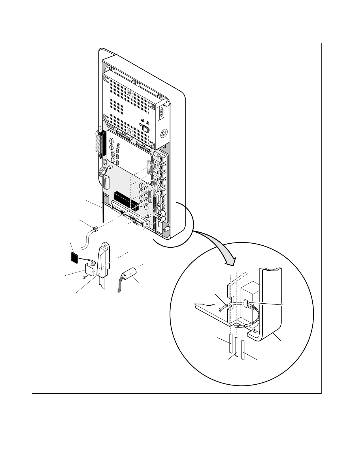
KRCU
INSTALLATION-DK16 KSU & PCB
SECTION 100-816-205
MARCH 1993
AC DC
POWER
–24V
NOTES
1.2.SUPPLIED IN PLASTIC BAG WITH
BASE UNIT.
DO NOT ROUTE POWER CORD WITH
OTHER CORDS.
AC POWER CORD
MODULAR
CONNECTOR
SELF-ADHESIVE
RUBBER PAD
1
AMPHENOL
CLAMP
1
AMPHENOL
CONNECTOR
2
RCA JACK
TIE WRAP
MODULAR
CORD (X5)
AMPHENOL
CORD (X1)
1
TIE WRAP
HOLDER
DK 16
BASE UNIT
PIN JACK
CORD (X2)
FIGURE 5-4
DK16 BASE KEY SERVICE UNIT WIRING CONNECTIONS
5-5
Page 76

INSTALLATION-DK16 KSU & PCB
SECTION 100-816-205
MARCH 1993
DK16 BASE
UNIT
HINGE
MOUNT
TB1 (FG2)
GREEN/YELLOW
FG2 WIRE AND PLUG
(FROM EXPANSION
UNIT – PLUGS INTO
TB1 OF BASE UNIT)
SAFETY LOCK
(SUPPLIED WITH
EXPANSION UNIT)
RIBBON CABLE (FROM EXPANSION UNIT – PLUGS
INTO EXPANSION CONNECTOR (P3) OF BASE UNIT)
PULL
LOCK
PUSH
UNLOCK
BACK OF DK16
EXPANSION UNIT
P3
RIBBON
CONNECTOR
LOCK
FIGURE 5-5
CONNECTING THE DK16 EXPANSION UNIT TO THE DK16 BASE UNIT
5-6
Page 77

INSTALLATION-DK16 KSU & PCB
SECTION 100-816-205
MARCH 1993
EXPANSION
UNIT
RIBBON CABLE
TO EXPANSION UNIT
EXPANSION
UNIT LATCH
EXPANSION
SAFETY LOCK
FG WIRE
FG2 WIRE
PULL
LOCK
PUSH
UNLOCK
FG SCREW
BASE UNIT
AC DC
DC POWER
MOUNTING
HOLE AND SCREW
FIGURE 5-6
MOUNTING THE DK16 EXPANSION UNIT
OFF BATTON
AC CORD
TIE WRAP HOLDER
5-7
Page 78

INSTALLATION-DK16 KSU & PCB
SECTION 100-816-205
MARCH 1993
EXPANSION UNIT
PCB
SLOT LOCK
SO6
SO4
SO7
LOCK
SO5
SIDE COVER
FIGURE 5-7
DK16 EXPANSION UNIT INTERIOR
5-8
Page 79

PULL
LOCK
PUSH
UNLOCK
INSTALLATION-DK16 KSU & PCB
SECTION 100-816-205
MARCH 1993
BATT
±
AC DC
DC POWER
KRCU
TIE WRAP
AMPHENOL
CONNECTOR
9 FT
AC POWER CORD
OFF BATTON
TO MDF
TIE WRAP
OPTIONAL AC GROUND WIRE
FROM FG TERMINAL TO EARTH
GROUND (COLD WATER PIPE)
TO AC OUTLET (DO NOT ROUTE
AC POWER CORD SIDE-BY-SIDE
WITH OTHER CABLES)
FIGURE 5-8
DK16 EXPANSION UNIT WIRING CONNECTIONS
5-9
Page 80

INSTALLATION-DK16 KSU & PCB
SECTION 100-816-205
MARCH 1993
13) Knock out the tab on the bottom of the side
cover.
14) Plug the AC power cable into an outlet and
then turn ON the power supply switch.
15) Install the side cover to the Expansion Key
Service Unit (Figure 5-7).
2.40 Reserve Power/Power Failure Options
2.41 The STRATA DK systems offer two options
to protect system operation in the event of a power
failure; the Reserve Power option (Paragraph 2.42-
2.44), and the Power Failure Emergency Transfer
option (Paragraph 17).
2.42 Reserve Power Option STRATA DK16 sys-
tem power supply provides the capability of connecting a reserve power source (two customer
supplied 12-volt batteries) to ensure uninterrupted
system operation in the event of a power failure. A
pre-assembled interface cable for installation of
the Reserve Power option is available from Toshiba
(PBTC-3M), refer to Figure 5-9.
IMPORTANT NOTE!
Local ordinances may dictate battery type
and installation details.
2.43 The batteries require a well-ventilated loca-
tion close (within 9 feet) to the system —the
interface cable is 9 feet long.
WARNING!
To reduce the risk of fire or injury to
persons, read and follow these instructions:
1. Use only the following type and size
batteries: 12-volt, gelcell.
2. Do not dispose of the batteries in a fire.
The cells may explode. Check with
local codes for possible special disposal instructions.
3. Do not open or mutilate the batteries.
Released electrolyte is corrosive and
may cause damage to the eyes or skin.
It may be toxic if swallowed.
4. Exercise care in handling batteries in
order not to short the battery with conduction materials such as rings, bracelets, and keys. The battery or conductor may overheat and cause burns.
5. Charge the batteries provided with or
identified for use with this product
only in accordance with the instructions and limitations specified in this
manual.
6. Observe proper polarity orientation
between the batteries and battery
charger.
2.44 Reserve Power Installation. Install the Re-
serve Power option in accordance with the following steps (refer to Figure 5-9):
1) Connect the PBTC-3M black jumper wire
from the positive terminal of one 12VDC
battery to the negative terminal of the second
12VDC battery.
2) Ensure that a serviceable 10-ampere fuse is
installed in the in-line fuse holder of the PBTC-
3M battery cable.
3) Connect the white lead of the PBTC-3M battery cable to the open positive terminal of the
12VDC battery. Connect the black lead to the
open negative terminal of the second 12VDC
battery.
IMPORTANT NOTE!
The KSU must be connected to the live
operating (HOT) AC power source, and
the power supply ON/OFF switch set to
ON prior to the final step of connecting the
reserve power batteries to the power supply via the BATT +/- receptacle. If the
batteries are connected after AC power is
lost, reserve power will not function.
4) Connect the PBTC-3M battery cable twoprong male plug to the power supply BATT +/
- receptacle.
5) To test reserve power operation, disconnect
the system AC power plug with the power
supply power ON/OFF switch in the ON position. The system should continue to operate
without any interruption.
5-10
Page 81

INSTALLATION-DK16 KSU & PCB
SECTION 100-816-205
MARCH 1993
KPSU16
BATT
POWER SUPPLY
ACTUAL
SIZE
+
–
BLACK
IN-LINE
FUSE HOLDER
10 A
(FUSE PROVIDED)
16AWG
TWO-PRONG
MALE CONNECTOR
(PRE-ASSEMBLED)
WHITE
BLACK
–
12 VDC
BATTERY
RING TERMINALS 3/8 IN.
+
PBTC-3M
BATTERY CABLE
WITH RING TERMINALS
AND PPSU CONNECTOR
(LENGTH 9 FEET)
WHITE
–
12 VDC
BATTERY
BLACK JUMPER
WITH RING TERMINALS
(PROVIDED)
+
FIGURE 5-9
RESERVE POWER/BATTERY WIRING
3 POWER SUPPLY REMOVAL AND
REPLACEMENT
3.00 The power supply (KSPU 16) comes factory-
installed in the Base Key Service Unit (Figure 5-
10); if necessary, it can be removed and replaced.
3.10 Power Supply Removal
1) Make sure that the power supply switch is
OFF and that the AC power cable is not
plugged into an outlet. Confirm that green AC
LED is not lit.
2) Unplug reserve battery cable from BATT connector of power supply (Figure 5-10).
3) Remove K4RCU PCB and Expansion Unit
4) Unplug the DC cable from the DC OUT connector (see Figure 5-10).
5) Remove FG screw from left side of power
supply to free FG wire/terminal and building
ground wire.
6) Remove the six screws that attach the power
supply to the Base Key Service Unit. Remove
power supply.
3.20 Power Supply Replacement
1) Route FG1 wire (soldered on both sides of
Base Unit motherboard) so it will be under the
power supply inside of standoffs (see Figure
5-10).
2) Set the power supply in its proper place in the
Base Key Service Unit (see Figure 5-9).
3) Secure the power supply to the Base Key
Service Unit with the six screws.
5-11
Page 82

INSTALLATION-DK16 KSU & PCB
SECTION 100-816-205
MARCH 1993
MOUNTING
SCREWS (6)
RESERVE BATTERY
CONNECTOR
KPSU16A
POWER SUPPLY
AC POWER CABLE
FG SCREW
(LEFT SIDE)
DC CABLE
(FG) GREEN/YELLOW
WIRE WITH RING
TERMINAL THAT IS
FASTENED TO
POWER SUPPLY
FG SCREW
DC OUT (P9) CONNECTOR
(KPSU16 VOLTAGE TEST POINTS)
PULL
LOCK
PUSH
UNLOCK
KRCU
FG1 GREEN/YELLOW WIRE RUN
UNDERNEATH POWER SUPPLY
BEHIND STAND-OFFS
GREEN/YELLOW WIRE
(RIGHT-HAND SIDE)
AC DC
DC POWER
BATT
±
MOUNTING HOLE
AND SCREW
DC POWER
SWITCH
–24V CIRCUIT
BREAKER
(RIGHT SIDE)
FIGURE 5-10
POWER SUPPLY (KPSU16)
4) Plug the DC cable into the DC OUT connector.
Green/yellow wire is on right-hand side (Figure
5-10).
5) Fasten FG green/yellow wire ring terminal and
building ground wire to the left side of the
power supply with the FG screw.
6) Re-install K4RCU PCB (if required).
7) Plug the AC power cable into an outlet and
turn ON the power supply switch.
8) Refer to Paragraph 2.10 to confirm that the
power supply is working properly.
9) Plug reserve battery cable into BATT connector of power supply (Figure 5-10).
5-12
Page 83

INSTALLATION-DK 16 KSU & PCB
SECTION 100-816-205
MARCH 1993
PART II. DK16 PRINTED CIRCUIT BOARD
INSTALLATION
4 GENERAL
4.01 This chapter provides procedures for installa-
tion of STRATA DK16 system printed circuit boards
(PCBs) into the Base and Expansion units. This
includes installation instructions, optional configuration information, and wiring and programming
considerations for each PCB.
4.02 Be sure the power supply has been tested,
and the ground has been checked. (See Chapter 5,
Section I for the power supply and Chapter 3 for
grounding.)
4.03 It is recommended to install the Base Unit
option PCBs K4RCU and/or KSTU before mounting the Base KSU on the wall.
4.04 Begin Expansion PCB installation only after
completion of Expansion Unit installation (see Chapter 5, Section I).
5 DK16 PCB INSTALLATION
CONSIDERATIONS
5.01 The STRATA DK16 Base Unit comes stan-
dard with eight digital telephone circuits (ports) and
four CO line circuits. The digital circuits are integrated into the motherboard, and the CO line circuits are on the KCOU which is attached to the P6
and P7 connectors on the motherboard. The common control unit, like the digital telephone circuits,
is built into the motherboard.
5.10 DK16 Base Unit PCBs
5.11 The Base Unit can support an optional KSTU
printed circuit board (PCB) which provides four
standard telephone circuits (ports). In addition, a
K4RCU PCB can be installed to receive DTMF
tones, and detect busy tone for Automatic Busy
Redial (ABR) operation.
5.20 DK16 Expansion Unit PCBs
5.21 The Expansion Unit can support a number of
PCBs: it can support a PCOU which provides four
CO line circuits; one or two KCDUs which provide
two CO line circuits and four digital telephone
circuits (ports); a PDKU which provides eight digital
telephone circuits (ports); a PEKU which provides
eight electronic telephone circuits (ports); a PESU
which provides two standard and four electronic
telephone circuits (ports); a PSTU which provides
eight standard telephone circuits (ports); and a
PIOU or PIOUS which both provide a port for a
Station Message Detail Recording (SMDR) device,
an interface for remote maintenance, and relay
control options.
5.22 The DK16 Expansion Unit does not come from
the factory with any PCBs installed. Any of the
PCBs listed above can fit into any of the unit's four
universal slots; however, it is recommended that
PCBs that support electronic or digital telephones
be installed into Slots 04 and 05, because Slots 06
and 07 cannot support Off-hook Call Announce or
Data Interface Units (DIUs).
Recommended PCB slot assignments:
•
KCDU — Slot 04 and 05 (2 maximum)
•
PDKU, PEKU, PESU, PSTU — Slot 04 (1 maximum, cannot be installed with KCDU.)
•
PCOU — Slot 05 (1 maximum, cannot be installed with KCDU.)
•
PIOU/PIOUS — Slot 06 (1 maximum)
5.30 PCB Option Considerations
5.31 PCBs may be configured for a variety of
hardware and software options. Hardware options
are defined as either internal (generally related to
optional PCB subassemblies) or external (related
to connection of peripheral equipment such as
background music, voice mail, etc). Hardware and
software options for each PCB are identified in the
individual PCB installation procedures in this chapter.
5.32 PCB Hardware Options. Each PCB must be
configured for the applicable hardware options
prior to installation of the PCB. Configuration instructions for internal hardware options are provided in the individual PCB installation procedures
in this chapter. Configuration instructions for external hardware options are provided in Peripheral
Installation, Section 100-816-207.
5-13
Page 84

INSTALLATION-DK 16 KSU & PCB
SECTION 100-816-205
MARCH 1993
5.33 PCB Software Options. PCBs are configured for software options through programming,
after installation of the PCBs in the KSU. A programming overview for each PCB is provided in the
individual PCB installation procedures in this chapter. Refer to the Programming Procedures, Section
100-816-300, for detailed programming instructions.
5.40 PCB Installation/Power Supply Considerations
5.41 Whenever removing or installing PCBs it is
recommended that the power supply be OFF.
6 BASE UNIT STANDARD TELEPHONE
INTERFACE UNIT (KSTU)
6.00 General
6.01 The optional KSTU provides four standard
telephone circuits and it can only be installed in the
Base Unit. The KSTU supports the two-wire devices such as standard telephones, Auto Attendant
devices, voice mail machines, and facsimile machines. The KSTU can also support an alternate
Background Music (BGM) source on circuit 4.
NOTE:
For the system to recognize the Dual-Tone
Multi-Frequency (DTMF) tones generated by
standard telephones (or any other device connected to a KSTU port), a K4RCU must be
installed in the Base Unit.
6.02 The KSTU is shown in Figure 5-11 and its
connectors and controls are described in Table 5A.
6.10 KSTU Configuration
6.11 The KSTU only has to be configured for the
ring generator voltage level, nothing else. Before
installing the KSTU in the Base Unit, set the SW540
ring generator to 130V P-P or 190V P-P. Most
standard telephones and two-wire devices require
190; however, some devices may experience ringtrip at 190, and should be set at 130.
6.20 KSTU Installation Procedure
6.21 Install the KSTU in accordance with the follow-
ing steps:
1) Make sure that the power supply switch is
MOUNTING
SCREW
P508
P8
3 2 1
130
190
FIGURE 5-11
KSTU OPTIONS AND CONNECTORS
SW540
PLASTIC
STAND-OFF
KSTU
P4
RED
(WIRE)
P504
RED
MOUNTING
SCREW
5-14
Page 85

CONTROL/INDICATOR/
CONNECTOR
(Figure 5-11)
INSTALLATION-DK 16 KSU & PCB
SECTION 100-816-205
MARCH 1993
TABLE 5-A
KSTU CONTROLS AND INTERFACE CONNECTORS
TYPE OF COMPONENT DESCRIPTION
Ring Voltage Jumper
Plug SW540
Connector P508
Connector Cable P504
OFF.
2) Plug the KSTU cable into the P4 connector on
the motherboard in the Base Unit. The red
wire on the cable should match up with pin 1
on the lower side of the connector.
3) Plug the KSTU P508 female connector into
the P8 male connector on the motherboard.
4) Secure the KSTU to the standoffs with the two
provided screws.
Three-terminal jumper
Female Connector
Cable
Sets ring generator voltage level for all
circuits:
H = 190V P-P
L = 130V P-P
Mates to male connector P8 on the
motherboard.
Connects to P4 connector on the
motherboard.
Program 10-2
•
Used to set standard telephone ringing option.
•
Not required for Background Music (BGM) connection.
Program 19
•
Used for BGM connection to KSTU Port 11.
NOTE:
KSTU Ports (08~11) are fixed. They are assigned even if a KSTU is not installed.
6.30 KSTU Wiring
6.31 Refer to Base Unit Wiring in Section 100-816-
208 for KSTU wiring.
6.32 The KSTU must be connected to a OL13A (or
equivalent) type lines for off-premises stations.
(300 ohms loop resistance max., including the
telephone or other devices DC off hook resistance.
6.40 KSTU Programming Overview
6.41 The following parameters may be specified for
the KSTU:
Program 03
•
Specify code 31 for KSTU slot.
Program 31
•
Used to configure all KSTU ports connected to
voice mail (see Chapter 7 for voice mail installation).
7 DIGITAL TELEPHONE INTERFACE
UNIT (PDKU)
7.00 General
7.01 The Digital Telephone Interface Unit (PDKU)
provides eight ports/circuits for digital telephones
and it can only be installed in the Expansion Unit.
The PDKU can also support Integrated Data Interface Units (PDIU-DIs/PDIU-DI2s), Stand-alone Data
Interface Units (PDIU-DSs), a Digital Door Phone/
Lock Control Unit (DDCB), a Digital Direct Station
Selection Console (DDSS), and Add-on Modules
(ADMs). The DDSS console, DDCB, and PDIUDSs are wired directly to the PDKU and require no
additional hardware, but do require their own dedicated ports/circuits. The PDIU-DI/PDIU-DI2 or the
ADM shares with its accompanying digital tele-
5-15
Page 86

INSTALLATION-DK 16 KSU & PCB
SECTION 100-816-205
MARCH 1993
phone the same wire pair and circuit on the PDKU.
The PDKU (Figure 5-12) has no controls.
NOTE:
The PDIU-DI attaches to 1000-series Digital
Telephones, and the PDIU-DI2 attaches to
2000-series Digital Telephones.
7.10 PDKU Hardware Options
7.11 The PDKU supports the hardware options
noted below. Unlike the other PCBs, there are no
controls on the PDKU that need to be set for
options.
Internal option:
•
none
External option:
•
DDSS console
•
PDIU-DS
•
PDIU-DI/PDIU-DI2
•
DDCB
NOTE:
There are two versions of the PDKU: PDKU1,
and PDKU2. These versions are identical
except for the number of Data Interface Units
(DIUs) they can support (see Paragraphs 7.14
and 7.15). Also, PDKU2 supports continuous
DTMF tones with 2000-series digital telephones, but PDKU1 does not support continuous DTMF tones.
7.12 Hardware Configuration
7.13 DDSS Console Configuration. Refer to Sta-
tion Apparatus Installation, Section 100-816-206,
for installation procedures for the DDSS console.
The DDSS console requires dedicated use of Circuit 8 of the PDKU.
7.14 PDIU-DS Configuration. Refer to Peripherals Installation, Section 100-816-207, for installation procedures for the PDIU-DS. A PDIU-DS can
be connected to Circuits 1 ~ 7 on a PDKU1 or
50-PIN AMPHENOL CONNECTOR (FEMALE)
BACKPLANE CONNECTOR
FIGURE 5-12
PDKU INTERFACE CONNECTION
5-16
Page 87

INSTALLATION-DK 16 KSU & PCB
SECTION 100-816-205
MARCH 1993
Circuits 1 ~ 8 on a PDKU2; the circuit must be
dedicated to the PDIU-DS.
7.15 PDIU-DI/PDIU-DI2 Configuration. Refer to
Station Apparatus Installation, Section 100-816-
206, and Peripherals Installation, Chapter 7, for
installation procedures for the PDIU-DI/PDIU-DI2.
PDIU-DIs/PDIU-DI2s can be equipped with any
digital telephone connected to PDKU Circuits 1 ~ 7
with PDKU1 or Circuits 1 ~ 8 with PDKU2.
7.16 DDCB Configuration. Refer to Peripherals
Installation, Section 100-816-207, for installation
procedures for the DDCB. The DDCB must be
connected to the Circuit 8 on the PDKU.
7.17 ADM Configuration. Refer to Section 100816-206, Paragraph 7.00.
7.20 PDKU Installation Procedure
7.21 Install the PDKU in accordance with the fol-
lowing steps:
1) Remove the PCB from its protective packaging.
2) Insert the PDKU into the appropriate slot (see
Paragraph 5.22, and apply firm, even pressure to ensure proper mating of connectors.
NOTE:
Ensure the PDKU's component side is facing
right when installing it in the KSU.
4) After installing the PDKU, gently pull the PCB
outward. If the connectors are properly mated,
a slight resistance will be felt.
7.30 PDKU Wiring
7.31 Refer to PDKU Wiring Diagrams, Chapter 8,
for wiring/interconnecting details.
7.40 PDKU Programming Overview
7.41 The following parameters may be specified,
through programming, for the PDKU:
Program 03
•
Specify code 61 if no options are installed on a
PDKU.
•
Specify code 62 to indicate a PDKU that will
support stations that must receive Off-hook Call
Announce (OCA).
• Specify code 64 to indicate a PDKU configured
for a DDSS console and OCA.
Programs 20, 21, and 22
•
Use to configure PDIU-DIs/PDIU-DI2s and PDIUDSs.
Programs 28 and 29
•
Use for DDSS assignments.
Program 30
•
Adjusts initial off-hook volume level for digital
telephone handsets.
Program 92-5
•
Initializes initial ringing, speaker, and muted ring
volume levels of digital telephones.
Programs 77-1, 77-2, and 79
•
Used for DDCB and door phone assignments
8 ELECTRONIC TELEPHONE
INTERFACE UNIT (PEKU)
8.00 General
8.01 The Electronic Telephone Interface Unit
(PEKU) provides eight ports for electronic telephones and it must be installed in the Expansion
Unit. It is recommended that the current 6500series be used, because this series consumes the
least amount of power.
8.02 The PEKU can be configured to receive Offhook Call Announce (OCA) by installing an Offhook Call Announce Unit (EOCU). It can also be
configured to support an HDSS console and an
external Background Music (BGM) source connector. An external amplifier for two-CO line conference calls can also be connected to Circuits 6 and
7 of the PEKU. The HDSS console, the external
amplifier, and the BGM source, are wired directly to
the PEKU and require no additional hardware, but
do require specific ports/circuits. Electronic telephones also wire directly to the PEKU, and they can
be connected to any PEKU circuit.
8.03 PEKU controls and interface connectors are
shown in Figure 5-13 and described in Table 5-B.
8.10 PEKU Hardware Options
8.11 The PEKU supports the following hardware
options:
Internal Options
•
Off-hook Call Announce Unit (EOCU)
External Options
5-17
Page 88

INSTALLATION-DK 16 KSU & PCB
SECTION 100-816-205
MARCH 1993
50-PIN AMPHENOL CONNECTOR (FEMALE)
SW1
EKT
DSS
W5, cut for
BGM option
W5
BACKPLANE CONNECTOR
FIGURE 5-13
PEKU CONTROLS AND INTERFACE CONNECTORS
•
HDSS console
•
BGM source connection
•
External Amplifier
8.12 Off-hook Call Announce (EOCU) Installation. Install the Off-hook Call Announce Unit
(EOCU) in accordance with the following steps:
1) Remove the PCB from its protective packaging.
NOTE:
PEKU connectors P10, P20, P40, P50, and
P60 are positioned to allow installation of the
EOCU only in the proper position (Figure 5-
13).
2) Mate EOCU connectors J10, J20, J40, J50,
and J60 with PEKU connectors P10, P20,
P40, P50, and P60 (Figure 5-14).
3) Apply firm, even pressure to EOCU to ensure
proper mating of connectors.
P10
P20
P40
P60P50
4) Use a 3-pair cable for making connections
between the PEKU and the Off-hook Call
Announce (OCA) electronic telephone. Refer
to Wiring Diagrams, Section 100-816-208, for
wiring/interconnecting details.
5) Refer to Station Apparatus Installation, Section 100-816-206, for procedures to upgrade
electronic telephones for OCA.
8.13 HDSS Console Configuration. Configure
the PEKU to support an HDSS console in accordance with the following steps:
1) Remove the PCB from its protective packaging.
2) Set the SW1 DSS/EKT switch to DSS.
3) Refer to Station Apparatus Installation, Section 100-816-206, for installation procedures
for the HDSS console. The HDSS console
requires dedicated use of Circuits 7 and 8 of
the PEKU PCB.
5-18
Page 89

CONTROL/INDICATOR/
CONNECTOR (Figure 5-13)
INSTALLATION-DK 16 KSU & PCB
SECTION 100-816-205
MARCH 1993
TABLE 5-B
PEKU CONTROLS AND INTERFACE CONNECTORS
TYPE OF COMPONENT DESCRIPTION
Off-hook Call
Announce P10
Off-hook Call
Announce P20
Off-hook Call
Announce P40
Off-hook Call
Announce P50
Off-hook Call
Announce P60
DSS/EKT DSS Console/
Electronic Telephone
SW1 Switch
10-pin connector Interface connector for optional Off-hook
Call Announce subassembly
connector (used in conjunction with P20,
P40, P50, and P60).
10-pin connector Interface connector for optional Off-hook
Call Announce subassembly
connector (used in conjunction with P10,
P40, P50, and P60).
10-pin connector Interface connector for optional Off-hook
Call Announce subassembly
connector (used in conjunction with P10,
P20, P50, and P60).
10-pin connector Interface connector for optional Off-hook
Call Announce subassembly
connector (used in conjunction with P10,
P20, P40, and P60).
10-pin connector Interface connector for optional Off-hook
Call Announce subassembly
connector (used in conjunction with P10,
P20, P40, and P50).
Two-position slide switch Configures PEKU for operation with either
an HDSS console or electronic
telephones.
BGM source connection
W5 Jumper Wire
8.14 Background Music (BGM) Configuration.
Configure the PEKU to support a BGM source in
accordance with the following steps:
1) Remove the PCB from its protective packaging.
2) Cut the W5 (BGM) jumper wire on the PEKU
PCB.
3) Refer to Peripherals Installation, Section 100-
816-207, for installation procedures for BGM
connection.
White jumper wire
When cut, configures PEKU for BGM
source connection.
8.15 External Amplifier Configuration. The
PEKU does not have to be configured to support an
external amplifier. However, the system must be
programmed for one; see Paragraph 8.40. See
Peripherals Installation, Section 100-816-207, for
external amplifier installation instructions.
8.20 PEKU Installation Procedure
8.21 Install the PEKU in accordance with the fol-
lowing steps:
1) Remove the PCB from its protective packaging.
5-19
Page 90
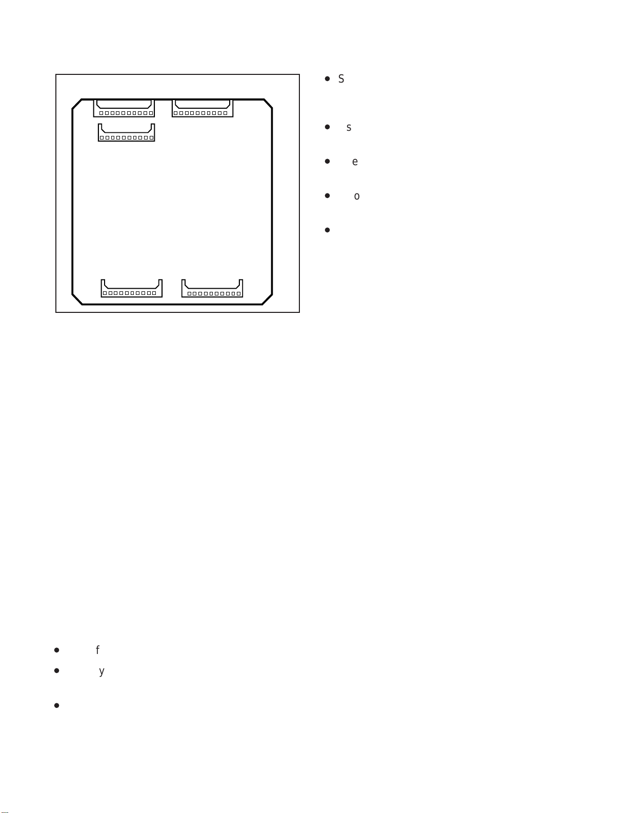
INSTALLATION-DK 16 KSU & PCB
SECTION 100-816-205
MARCH 1993
J60
J40
J50
J20 J10
FIGURE 5-14
OFF-HOOK CALL ANNOUNCE UNIT (EOCU)
INTERFACE CONNECTORS
2) Ensure the PEKU has been configured for the
appropriate hardware options (refer to Paragraph 8.10).
3) Insert the PEKU into the appropriate slot (refer
to Paragraph 5.22), and apply firm, even pressure to ensure proper mating of connectors.
4) After installing the PEKU, gently pull the PCB
outward. If the connectors are properly mated,
a slight resistance will be felt.
8.30 PEKU Wiring
8.31 Refer to PEKU Wiring Diagrams, Section
100-816-208, for wiring/interconnecting details.
•
Specify code 24 to indicate a PEKU configured
for OCA and an HDSS console.
Program 10-2
•
Used for BGM connection.
Program 10-3
•
Used for external amplifier connection.
Program 19
•
Also used for BGM connection.
Programs 28 and 29
•
Used for HDSS assignments.
9 STANDARD TELEPHONE
INTERFACE UNIT (PSTU)
9.00 General
9.01 The Standard Telephone Interface Unit
(PSTU) provides an interface between standard
telephones or two-wire devices and the system,
and it must be installed in the Expansion Unit. The
PSTU PCB adds eight standard telephone lines to
the system. The PSTU can also support a Background Music (BGM) source.
NOTE:
For the system to recognize the Dual-Tone
Multi-Frequency (DTMF) tones generated by
a standard telephone (or any other device
connected to a PSTU port), a DTMF Receiver
Unit (K4RCU) must be installed in the Base
Unit.
9.02 PSTU controls are shown in Figure 5-15 and
described in Table 5-C.
9.10 PSTU (1 and 2) Hardware Options
8.40 PEKU Programming Overview
8.41 The following parameters may be specified,
through programming, for the PEKU:
Program 03
•
Specify code 21 to indicate a station line PEKU.
•
Specify code 22 to indicate a PEKU configured
for OCA.
•
Specify code 23 to indicate a PEKU configured
for an HDSS console.
9.11 There are two PSTU versions (1 and 2): They
are identical except for the ring generator. The ring
generator on the original version (V.3) of PSTU1 is
fixed at a 190V P-P level, while the ring generator
on PSTU1 (V.4) and PSTU2 can be set for 130V PP or 190V P-P. The W1 jumper plug is used to set
the voltage level. Most standard telephones and
two-wire devices require the 190V P-P level; however, some devices may experience ring-trip with
190V P-P and they require the 130V P-P level.
5-20
Page 91

50-PIN AMPHENOL CONNECTOR (FEMALE)
INSTALLATION-DK 16 KSU & PCB
SECTION 100-816-205
MARCH 1993
SSTU
SUBUNIT
BACKPLANE CONNECTOR
FIGURE 5-15
PSTU AND SUBUNIT (SSTU)
W1
HL
W1 Ring Voltage
H = 190V P-P
L = 130V P-P
(For PSTU1 (V.4)
and PSTU2 only)
TABLE 5-C
PSTU CONTROLS AND INTERFACE CONNECTORS
CONTROL/INDICATOR/
CONNECTOR
(Figure 5-15)
Ring Voltage W1 Jumper
Plug (PSTU1 ( ) and
V.4
PSTU2 only)
NOTE:
PSTU1 (V.4) became available in November
1989. PSTU1(V.3) was discontinued.
9.12 Set the PSTU1 (V.4) or PSTU2 ring generator
level as required:
•
W1 set to H (190V P-P).
•
W1 set to L (130V P-P).
•
Two ringers maximum per port (H or L).
TYPE OF COMPONENT DESCRIPTION
Three-terminal jumper
Sets ring generator voltage level for all
circuits.
H = 190V P-P
L = 130V P-P
9.13 Unlike the PEKU or PESU, the PSTU does not
have to be configured for BGM: There is no jumper
wire to cut, etc.
9.20 PSTU Installation Procedure
9.21 Install the PSTU in accordance with the fol-
lowing steps:
1) Remove the PCB from its protective packaging. The protective shield on the back of the
PSTU is designed to protect the installer from
5-21
Page 92

INSTALLATION-DK 16 KSU & PCB
SECTION 100-816-205
MARCH 1993
potentially hazardous ring voltage. Do not
remove this shield.
2) Ensure that the PSTU subunit (SSTU) is securely attached to the PSTU (refer to Figure 5-
15).
NOTE:
W1, the ring generator level option, should be
set in the H position (factory) for initial installation.
3) Insert the PSTU into the appropriate slot (refer
to Paragraph 5.22), and apply firm, even pressure to ensure proper mating of connectors.
9.30 PSTU Wiring
9.31 Refer to PSTU Wiring Diagram, Section 100-
816-208, for wiring/interconnecting details.
9.32 The PSTU is registered for use with OL13A
type lines for off-premises stations.
9.40 PSTU Programming Overview
four electronic telephone interface circuits (5 ~ 8)
identical to PEKU circuits for connecting electronic
telephones, BGM or an external amplifier. The
PESU provides a ring generator for circuits 1 and 2
(with a ring voltage of either 190V P-P or 130V PP), and it must be installed in the Expansion Unit.
•
The PESU does not support an HDSS console
connection.
•
The PESU provides connectors to mount the
EOCU for OCA to electronic telephones.
NOTE:
A KSU must be installed in the Base Unit for
the system to recognize Dual-Tone MultiFrequency (DTMF) tones sent from standard
telephones or other two-wire devices that are
connected to the PESU.
10.02 The PESU controls and interface connectors are shown in Figure 5-16 and described in
Table 5-D.
10.10 PESU Hardware Options
9.41 The following parameters may be specified,
through programming, for the PSTU:
Program 03
•
Specify code 31 for all slots that have PSTUs
installed.
Program 31
•
Used to configure all PSTU ports connected to
voice mail (Section 100-816-207 for more details).
Program 10-2
•
Used to set standard telephone ringing option.
•
Also used for BGM connection.
Program 19
•
Used for BGM connection also.
10 STANDARD/ELECTRONIC TELE-
PHONE INTERFACE UNIT (PESU)
10.00 General
10.01 The Standard/Electronic Telephone Inter-
face Unit (PESU) provides two standard telephone
interface circuits (1 and 2) identical to PSTU circuits
for connection between standard telephones, or
two-wire devices, and the system. It also provides
10.11 The PESU supports the following hardware
options:
•
Internal option: Off-hook Call Announce
(EOCU).
NOTE:
Refer to Section 100-816-206 and Section
100-816-207 for installation of external options.
10.12 Off-hook Call Announce (EOCU) Installation. Install the Off-hook Call Announce in accor-
dance with the following steps:
1) Remove the PCB from its protective packaging.
NOTE:
PESU connectors P10, P20, P40, P50, and
P60 are positioned to allow installation of the
EOCU only in the proper position (refer to
Figure 5-16).
2) Mate the EOCU connectors J10, J20, J40,
J50, and J60 with the PESU connectors P10,
P20, P40, P50, and P60 (refer to Figure 5-16).
5-22
Page 93

INSTALLATION-DK 16 KSU & PCB
CUT W7 ONLY IF BGM IS CONNECTED TO
CIRCUIT 8.
SECTION 100-816-205
MARCH 1993
50-PIN
AMPHENOL
CONNECTOR
(FEMALE)
PESU
W7
ESTS
P40
P10
P60
P50
OPTIONAL
EOCU, EQUIP
FOR OCA
FEATURE
P20
UP
LH
P90
RING VOLTAGE OPTION (CIRCUITS 1 & 2):
L = LOW LEVEL (130V P-P)
H = HIGH LEVEL (190V P-P)
NOTE: Connect two ringers maximum per port (H or L).
PESU
FIGURE 5-16
PESU PCB OPTION LOCATION AND IDENTIFICATION
P70P80
ESTS: STANDARD TELEPHONE
INTERFACE, ALWAYS EQUIPPED
FROM FACTORY
BACKPLANE
CONNECTOR
5-23
Page 94

INSTALLATION-DK 16 KSU & PCB
SECTION 100-816-205
MARCH 1993
PESU CONTROLS AND INTERFACE CONNECTORS
TABLE 5-D
CONTROL/INDICATOR/
CONNECTOR (Figure 5-16)
Off-hook Call
Announce P10
Off-hook Call
Announce P20
Off-hook Call
Announce P40
Off-hook Call
Announce P50
Off-hook Call
Announce P60
TYPE OF COMPONENT DESCRIPTION
10-pin connector
10-pin connector
10-pin connector
10-pin connector
10-pin connector
Interface connector for optional Off-hook
Call Announce subassembly
connector (used in conjunction with P20,
P40, P50, and P60).
Interface connector for optional Off-hook
Call Announce subassembly
connector (used in conjunction with P10,
P40, P50, and P60).
Interface connector for optional Off-hook
Call Announce subassembly
connector (used in conjunction with P10,
P20, P50, and P60).
Interface connector for optional Off-hook
Call Announce subassembly
connector (used in conjunction with P10,
P20, P40, and P60).
Interface connector for optional Off-hook
Call Announce subassembly
connector (used in conjunction with P10,
P20, P40, and P50).
Ring Voltage Jumper
Plug P90
BGM W7 Jumper Pack
3) Apply firm, even pressure to the EOCU to
ensure proper mating of connectors.
4) Use 3-pair cable for connecting the PESU and
the OCA electronic telephone (refer to Wiring
Diagrams, Section 100-816-208, for wiring/
interconnecting details).
5) Refer to Station Apparatus Installation, Section 100-816-206, for procedures to add OCA
to electronic telephones.
Three-terminal jumper
White jumper wire
Sets ring generator voltage level for
circuits 1 and 2.
H = 190V P-P (factory setting)
L = 130V P-P
When cut, configures PESU, circuit 8,
for BGM source connection.
10.13 Background Music (BGM) Configuration. Configure the PESU to support a BGM source
in accordance with the following steps:
1) Remove the PCB from its protective packaging.
2) Cut the W7 (BGM) jumper wire on the PESU
PCB.
3) Refer to Peripherals Installation, Section 100-
816-207, for BGM installation procedures.
10.14 External Amplifier Configuration. The
PESU does not have to be configured to support an
5-24
Page 95

INSTALLATION-DK 16 KSU & PCB
SECTION 100-816-205
MARCH 1993
external amplifier. However, the system must be
programmed for one; see Paragraph 10.40. The
external amplifier requires Circuits 6 and 7 on the
PESU. See Peripherals Installation, Section 100-
816-207, for external amplifier installation instructions.
10.20 PESU Installation Procedure
10.21 Install the PESU in accordance with the
following steps:
1) Remove the PCB from its protective packaging. The protective shield on the back of the
PESU is designed to protect the installer from
potentially hazardous ring voltage. Do not
remove this shield.
2) Ensure that the PESU subunit (ESTS) is
securely attached to the PESU (refer to Figure
5-15).
3) If the electronic telephones connected to the
PESU must receive OCA calls, install the
EOCU subassembly PCB on the PESU per
Paragraph 10.12.
4) If a BGM source is connected to the PESU,
Circuit 8, cut W7.
5) Ensure that the ring voltage option, P90, is set
to the “H” position for initial installation. The “L”
position is used if devices connected to the
PESU trip ring voltage before answer.
6) Insert the PESU into the appropriate slot, and
apply firm, even pressure to ensure proper
mating of connectors.
Program 03
•
Specify code 25 for all slots that have PESUs
without EOCU.
•
Specify code 26 for all slots that have PESUs
equipped with EOCU.
NOTE:
A special code is not required to connect BGM
to a PESU.
Program 31
•
Configures the PESU Circuits 1 and 2 for connection to voice mail devices.
Program 10-2
•
Sets the standard telephone ring cadence for
normal or distinctive ringing and BGM source
connection.
Program 10-3
•
Used for external amplifier connection.
Program 19
•
Also used for BGM connection.
11 CO LINE UNIT (PCOU)
11.00 General
11.01 The PCOU PCB adds four CO lines to the
system and it can only be installed in the Expansion
Unit. The PCOU provides Ring Detection, Dial
Outpulsing and Hold; as well as Automatic Busy
Redial (ABR) circuitry. Each CO line can be programmed for Dual-Tone Multi-Frequency (DTMF)
or dial pulse.
NOTE:
There are two PCOU versions (1 and 2). They
are identical in fit/form/function and are interchangeable in all DK system models.
7) After installing the PESU, gently pull the PCB
outward. If the connectors are properly mated,
a slight resistance will be felt.
10.30 PESU Wiring
10.31 Refer to PESU Wiring Diagram, Section
100-816-208, for wiring/interconnecting details.
10.40 PESU Programming Overview
10.41 The following parameters may be specified,
through programming, for the PESU:
11.02 PCOU controls, indicators, and interface
connectors are shown in Figure 5-17 and described
in Table 5-E.
11.10 PCOU Hardware Options
11.11 There are no hardware options supported
by the PCOU.
11.20 PCOU Installation Procedure
11.21 Install the PCOU in accordance with the
following steps:
5-25
Page 96

INSTALLATION-DK 16 KSU & PCB
SECTION 100-816-205
MARCH 1993
1) Remove the PCB from its protective packaging.
NOTE:
The dB PAD switches SW101 through SW401
control excessive loudness resulting from close
proximity to the CO or PBX telephone office by
providing a 3 decibel (dB) signal level drop to, or
from, the PBX or CO when set to the 3 position.
Switches are factory-set to the 0 (0 dB signal
level drop) position.
2) If the Expansion Unit is located within one mile
of the PBX or CO telephone office, set dB PAD
switches SW101 through SW401 to the 3 (-3
dB signal level drop) position.
3) Insert the PCOU into the appropriate slot
(refer to Paragraph 2.22), and apply firm,
even pressure to ensure proper mating of
connectors.
4) After installing the PCOU, gently pull the PCB
outward. If the connectors are properly mated,
a slight resistance will be felt.
11.30 PCOU Wiring
11.31 Refer to PCOU Wiring Diagram, Section
100-816-208, for wiring/interconnecting details.
11.40 PCOU Programming Overview
11.41 The following parameters may be specified,
through programming, for the PCOU:
Program 03
•
Specify code 11 for the slot in which the PCOU
is installed.
Program 10-1
•
Allows/denies two-CO Line Conference and Direct Inward System Access (DISA).
Program 15
•
Assigns DTMF/Dial Pulse (DP) Dialing, Tenant
Service, DISA, and other attributes to each CO
line.
Program 16
•
Assigns CO lines to groups 81 ~ 88, and dial 9
group.
Program 40
•
Assigns stations access to CO lines (incoming
and outgoing access).
CO LINE MODULAR
JACK CIRCUITS 1 AND 2
SW101
0 3
PAD
BACKPLANE CONNECTOR
SW201
0 3
PAD
SW301
0 3
PAD
CO LINE MODULAR
JACK CIRCUITS 3 AND 4
1 2 3 4
SW401
0 3
PAD
CO LINE
LED'S
FIGURE 5-17
PCOU CONTROLS, INDICATORS, AND INTERFACE CONNECTORS
5-26
Page 97

CONTROL/INDICATOR/
CONNECTOR
(Figure 5-17)
CO Line Circuit 1
Indicator CD112
CO Line Circuit 2
Indicator CD212
CO Line Circuit 3
Indicator CD312
CO Line Circuit 4
Indicator CD412
INSTALLATION-DK 16 KSU & PCB
TABLE 5-E
PCOU CONTROLS, INDICATORS, AND INTERFACE CONNECTORS
TYPE OF COMPONENT DESCRIPTION
Red LED
Red LED
Red LED
Red LED
Lights to indicate CO line circuit 1 is in
operation (NOTE: CO line indicator will
not light unless PCOU is connected to
a CO).
Lights to indicate CO line circuit 2 is in
operation (NOTE: CO line indicator will
not light unless PCOU is connected to
a CO).
Lights to indicate CO line circuit 3 is in
operation (NOTE: CO line indicator will
not light unless PCOU is connected to
a CO).
Lights to indicate CO line circuit 4 is in
operation (NOTE: CO line indicator will
not light unless PCOU is connected to
a CO).
SECTION 100-816-205
MARCH 1993
J1 Connector
J2 Connector
PAD Switch SW101
PAD Switch SW201
PAD Switch SW301
PAD Switch SW401
Program 41
•
Assigns stations access to CO lines (outgoing
only).
Program 42-0, 1-8
•
Assigns behind PBX/CENTREX operation to
each CO line.
Programs 45 ~ 48
•
Defines Toll Restrictions for any CO line.
Programs 50 ~ 56
•
Defines Least Cost Routing using CO lines.
Modular connector
Modular connector
Two-position slide
Two-position slide
Two-position slide
Two-position slide
Interface connector for CO line circuits
1 and 2.
Interface connector for CO line circuits
3 and 4.
Enables 3dB signal level drop for CO line
circuit 1.
Enables 3dB signal level drop for CO line
circuit 2.
Enables 3dB signal level drop for CO line
circuit 3.
Enables 3dB signal level drop for CO line
circuit 4.
Program 78
•
Assigns special ringing of CO lines: Night Ring
Over Page, DISA, IMDU.
Programs 81 ~ 89
•
Assigns CO lines to ring selected stations.
•
Assigns Delayed Ringing to any CO line.
Program 93
•
Assigns names to CO lines.
5-27
Page 98

INSTALLATION-DK 16 KSU & PCB
SECTION 100-816-205
MARCH 1993
12 OPTION INTERFACE UNIT
(PIOU AND PIOUS)
12.00 General
12.01 The Option Interface Unit (PIOU or PIOUS)
provides a circuit interface with peripheral options.
A maximum of one PIOU or PIOUS PCB can be
installed in the system. The PIOU and PIOUS
support the same options, except the PIOUS
does not support Zone Paging (see Paragraph
12.11).
12.02 PIOU controls, indicators, and interface
connectors are shown in Figure 5-18 and described in Table 5-F. PIOUS information is provided in Figure 5-19 and Table 5-G.
12.03 The internal 600 ohm or 3 watt page amplifier of the PIOU is not supported by Strata
DK16.
12.10 PIOU and PIOUS Hardware Options
12.11 The PIOU and PIOUS support the following
STRATA DK16 hardware options:
Internal Options
•
Remote Maintenance Modem Unit (IMDU)
External Options
•
Alarm Sensor
•
Local Maintenance Terminal or Modem
•
SMDR Printer or Call Accounting Port
•
Remote Maintenance Port
•
Relay control options
•
Zone Page via relays (PIOU only)
NOTE:
Refer to Peripheral Equipment Installation,
Section 100-816-207, for installation of exter-
nal options.
12.12 Remote Maintenance Modem Unit (IMDU)
Installation. Install the Remote Maintenance Mo-
dem Unit (IMDU) in accordance with the following
steps:
1) Remove the PCB from its protective packaging.
50-PIN AMPHENOL CONNECTOR (FEMALE)
BACKPLANE CONNECTOR
SW2
P1
P2
P10
B
P13
P3
P11
B
P12
M
SPO
C.C.I.T.T.
SPI
N.O.
MODEM
TTYSMDR
J3
1200
SW1
300
TTY
SW3
FIGURE 5-18
PIOU CONTROLS, INDICATORS, AND INTERFACE CONNECTORS
5-28
Page 99

CONTROL/INDICATOR/
CONNECTOR
(Figure 5-18)
INSTALLATION-DK 16 KSU & PCB
SECTION 100-816-205
MARCH 1993
TABLE 5-F
PIOU CONTROLS AND INTERFACE CONNECTORS
TYPE OF COMPONENT DESCRIPTION
SMDR/TTY Interface
Connector J3
IMDU Connector P1
IMDU Connector P2
IMDU Connector P3
M/B Make/Break
Jumper Plug P10
M/B Make/Break
Jumper Plug P11
Alarm Sensor N.O./N.C.
Jumper Plug P12
CCITT/BELL Jumper
Plug P13
SMDR Baud Rate
Switch SW1
TTY Baud Rate Switch
SW2
Dual modular connector Interface connector for SMDR printer/
call accounting device and
maintenance terminal/modem.
10-pin connector
9-pin connector Interface connector for Remote
3-pin connector Interface connector for Remote
Three-terminal jumper plug
Three-terminal jumper plug Night/Hold Relay MAKE or BREAK
Three-terminal jumper plug Alarm sensor normally open or normally
Three-terminal jumper plug IMDU or external modem operating
Two-position slide switch
Two-position locking pushbutton switch
Interface connector for Remote
Maintenance Modem piggy-back module.
Maintenance Modem piggy-back module.
Maintenance Modem piggy-back module.
External Page/Door Lock Control Relay
MAKE or BREAK jumper plug.
jumper plug.
closed jumper plug.
specification jumper plug.
Selects baud rate (300 or 1200 bps) for
SMDR printer or call accounting device.
Selects baud rate (300 or 1200 bps) for
Remote Maintenance Modem piggy-back
module (IMDU) or external TTY jack.
Modem/TTY Switch
SW3
2) Set the SW2 baud rate switch on the front
panel to 300 or 1200, as appropriate, after the
PIOU/PIOUS has been installed in the Expansion Unit (in-300 bps—out-1200 bps).
3) Set SW3 to MODEM position for IMDU operation.
4) Set the P13 jumper plug on the PIOU to the
BELL position; or, cut the W4 jumper on the
PIOUS for BELL operation.
5) Mate IMDU connectors J1, J2, and J3 with
PIOU or PIOUS connectors P1, P2, and P3
Two-position slide switch
Enables PIOU for operation with IMDU
modem or TTY jack.
(refer to Figure 5-20).
NOTE:
PIOU or PIOUS connectors P1, P2, and P3
are positioned to allow installation of the IMDU
only in the proper position.
6) Apply firm, even pressure to IMDU to ensure
proper mating of connectors.
NOTE:
The IMDU default station intercom number is
619; and IMDU communication parameters are
7-bits, even parity, 1-stop bit.
7) Refer to Programming Procedures, Section
100-816-300, Program 77-1, and set LED 14
to ON to enable IMDU operation.
5-29
Page 100

INSTALLATION-DK 16 KSU & PCB
SECTION 100-816-205
MARCH 1993
TBI
TERMINAL
STRIP
600 DE NH ALM
TTY
SMDR
SW2
PIOUS
CD4
J3
SPT SPR DET DER NHR ALMTNHT ALMR
MAKE
BREAK
MAKE
BREAK
K2
K1
SW1
CCITT
BELL
W1
W2
SW3
NORMAL OPEN
W4
W3
NORMAL CLOSED
IMDU
P1
W4 NOT FACTORY
INSTALLED FOR BELL
MODEM SPECIFICATION
P2
P3
OPTIONAL IMDU PCB
REMOTE MAINTENANCE
MODEM
BACKPLANE
CONNECTOR
FIGURE 5-19
PIOUS PCB SWITCH/JUMPER, OPTION LOCATION
NOTE:
Refer to Remote Maintenance Procedures,
Section 100-816-600, for information regard-
ing the IMDU.
12.20 PIOU and PIOUS Installation Procedure
12.21 Install the PIOU or PIOUS in accordance
with the following steps:
1) Remove the PCB from its protective packaging.
2) Ensure the PIOU or PIOUS has been configured for the appropriate hardware options
(refer to Paragraph 12.10 and Section 100-
816-207).
3) Insert the PIOU or PIOUS into slot 06 in the
Expansion Unit, and apply firm, even pressure
to ensure proper mating of connectors.
4) After installing the PIOU or PIOUS, gently pull
the PCB outward. If the connectors are properly mated, a slight resistance will be felt.
12.30 PIOU and PIOUS Wiring
12.31 Refer to Peripheral Equipment Installation
(Section 100-816-207) and Wiring Diagrams (Sec-
tion 100-816-208) for PIOU/PIOUS wiring/interconnecting details.
12.40 PIOU and PIOUS Programming Overview
12.41 The following parameters may be specified,
through programming, for the PIOU and PIOUS:
Program 77-1
•
Assigns relay control and IMDU options.
Program 60
•
Assigns SMDR options.
Program 78
•
Enables Night Ringing over External Page.
5-30
 Loading...