

Page 1
E6581295⑥
TOSVERT VF-AS1/PS1
Option Instruction Manual
DEV002Z-1
Make sure that this instruction manual is delivered to the end user
1.
of
the DeviceNet option for the VF-AS1/PS1.
Read this manual before installing or operating the DeviceNet option
2.
for the VF-AS1/PS1.
* The data given in this manual are subject to change without notice.
© Toshiba Schneider Inverter Corporation
And keep it in a safe place for reference.
NOTICE
All rights reserved.
2005
Page 2
Safety precautions
On the inverter and in its instruction manual, important information is contained for
preventing injuries to users and damages to assets and for proper use of the device.
Read the instruction manual attached to VF-AS1/PS1 along with this instruction manual
for completely understanding the safety precautions and adhere to the contents of these
manuals.
Explanation of markings
Marking Meaning of marking
E6581295⑥
Danger
Warning
(*1) Such things as injury, burns or shock that will not require hospitalization or long periods of
outpatient treatment.
(*2) Physical property damage refers to wide-ranging damage to assets and materials.
Meanings of symbols
Marking Meaning of marking
Indicates prohibition (Don't do it).
Indicates something mandatory (must be done).
Indicates danger.
Indicates warning.
Indicates that errors in operation may lead to death or serious injury.
Indicates that errors in operation may lead to injury (*1) to people or that these errors
may cause damage to physical property. (*2)
What is prohibited will be described in or near the symbol in either text or picture
form.
What is mandatory will be described in or near the symbol in either text or picture form.
What is dangerous will be described in or near the symbol in either text or picture form.
What the warning should be applied to will be described in or near the symbol in
either text or picture form.
- 1 -
Page 3
■ General Operation
Disassembly
prohibited
Prohibited
Mandatory
■ Transportation & installation
Prohibited
Mandatory
▼ Never disassemble, modify or repair.
Doing so could result in electric shock, fire and injury. For repairs, call your sales
agency.
▼ Do not attach this option to any inverter other than the VF-AS1/PS1.
Doing so could result in electric shock or fire.
▼ When the inverter is energized, never detach the this option from the VF-AS1/PS1.
Doing so could result in electric shock.
▼ Don't place or insert any kind of object into the DEV002Z (electrical wire cuttings, rods,
wires).
Doing so could result in electric shock or fire.
▼ Do not allow water or any other fluid to come in contact with the DEV002Z.
Doing so could result in electric shock or fire.
▼ Turn off the VF-AS1/PS1 when installing and wiring this option.
▼ If the inverter begins to emit smoke or an unusual odor, or unusual sounds, immediately
turn power off.
If the equipment is continued in operation in such a state, the result may be fire. Call
your local sales agency for repairs.
▼ Do not operate the inverter if it is damaged or any component is missing.
Doing so could result in electric shock or fire. Call your local sales agency for repairs.
▼ Do not place any inflammable substances near the VF-AS1/PS1 Inverter.
If an accident occurs in which flame is emitted, this could lead to fire.
▼ Do not install in any location where the inverter could come into contact with water or
other fluids.
Doing so could result in electric shock or fire.
▼ When installing this option, be careful not to touch the leads from parts on the reverse
side of its circuit board.
Doing so could result in injury.
▼ Operate under the environmental conditions prescribed in the instruction manual.
Operations under any other conditions may result in malfunction.
Danger
Danger
E6581295⑥
- 2 -
Page 4
■ Wiring
Mandatory
■ Operations
Prohibited
■ Disposal
Mandatory
E6581295⑥
Danger
▼ Shut off power when installing and wiring this option.
Wait at least 15 minutes and check to make sure that the charge lamp (VF-AS1/PS1) is
no longer lit.
▼ Tighten the screws on the terminal block to the specified torque (Refer to Section 4.1).
If the screws are not tightened to the specified torque, it may lead to fire.
▼ Electrical construction work must be done by a qualified expert.
Installation or connection of input power by someone who does not have that expert
knowledge may result in fire or electric shock.
Danger
▼ Do not touch switches when the hands are wet and do not try to clean the inverter with
a damp cloth.
Doing so could result in electric shock.
▼ Do not pull on any cable itself.
Doing so could result in damage or malfunction.
Warning
▼ For safety's sake, do not dispose of the disused inverter yourself but ask an industrial
waste disposal agent (*).
If the collection, transport and disposal of industrial waste is done by someone who is
not licensed for that job, it is a punishable violation of the law. (Laws in regard to
cleaning and processing of waste materials)
(*) Persons who specialize in the processing of waste and known as “industrial waste
product collectors and transporters” or “industrial waste disposal persons.”
Notes on use
▼ Do not install the inverter where the temperature or the humidity will change rapidly.
▼ Keep a distance of 20cm or more between the inverter's power cable and the data
transmission cable.
Or the inverter might malfunction because of noise.
▼ Insert a magnetic contactor or similar device between the inverter and the power supply
to ensure that power is turned off if an emergency stop command is entered through the
network.
Notes
- 3 -
Page 5
Introduction
Thank you for purchasing a “VF-AS1/PS1 DeviceNet Option (DEV002Z),” for TOSVERT
VF-AS1/PS1 inverter. Installing this option in the VF-AS1/PS1 and using it together, data
communication can be made with a host computer or other device via DeviceNet. Please
read the entire manual carefully before attempting to control your inverter via DeviceNet
connection.
Besides this instruction manual, the “DEV002Z Function Manual” is required to develop
software communicating with VF-AS1/PS1. In such a case, please get in touch with our
branch offices or sales offices. (“DEV002Z Function Manual”: E6581281).
This manual is also aimed at the operator using "VF-AS1/PS1 DeviceNet option", so please
use it for future maintenance and inspection.
■ Explanation of model number of DeviceNet TM option
DEV 002 Z - 1
Revision No.
Cable length (cable between inverter and unit), Z: No cable
E6581295⑥
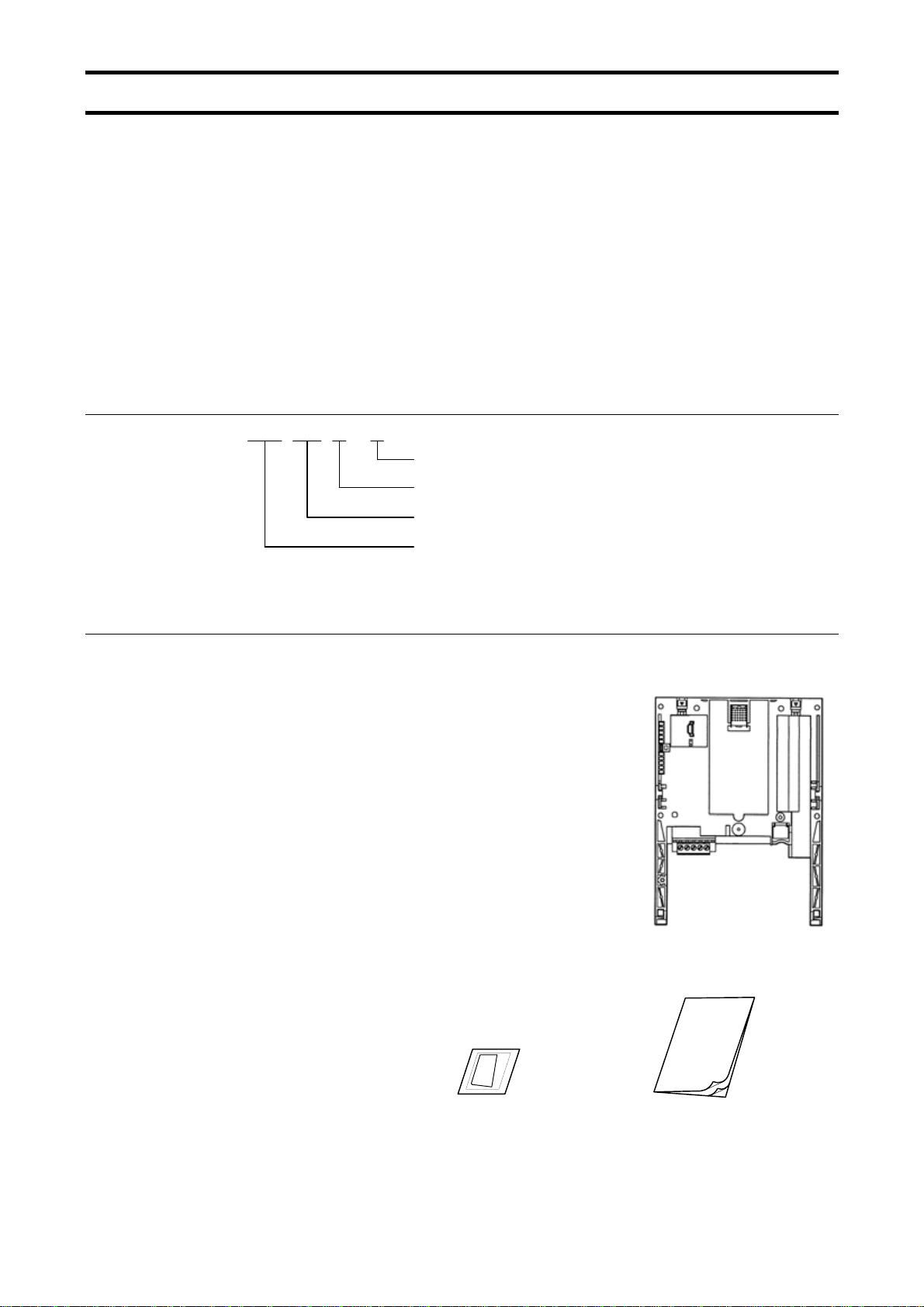
■ Check of accessories
DeviceNet option is shipped together with the following items in the package. Contact your
sales agency if any of these is missing.
• VF-AS1/PS1 DeviceNet
(DEV002Z)
• DeviceNet open connector ....... 1 pcs.
(Connected to the DEV002Z)
• Instruction manual for the VF-AS1/PS1 DeviceNet
(E6581295)
• LED name label ....... 1 pcs.
DeviceNet model number
DeviceNet
option ....... 1 board
option (this manual) ....... 1 copy
Manual
- 4 -
Page 6

E6581295⑥
Contents
1. OVERVIEW ..............................................................................................................................................6
2. EXTERIOR FEATURES...........................................................................................................................7
2.1. DeviceNet connector.......................................................................................................................7
2.2. DeviceNet indicator .........................................................................................................................8
3. INSTALLING THE DEV002Z....................................................................................................................9
4. CONNECTING TO THE NETWORK .....................................................................................................10
4.1. Installation method ........................................................................................................................10
4.2. Network Grounding .......................................................................................................................11
4.3. Setting a MAC ID number and a network baud rate .....................................................................12
5. COMMUNICATIONS-RELATED PARAMETERS..................................................................................13
5.1. f851: Communication Loss Action Setting (Network breaks)..................................................14
5.2. f852: Preset speed operation selection...................................................................................14
5.3. f830: Assembly Object Setting ................................................................................................15
6. DEVICENET LOCAL/REMOTE OPERATION .......................................................................................18
7. SPECIFICATIONS .................................................................................................................................19
8. WARRANTY...........................................................................................................................................19
- 5 -
Page 7

1. Overview
The DEV002Z interface allows the VF-AS1/PS1 inverter to be connected into a
DeviceNet network. DeviceNet supports a maximum of 64 nodes, allowing for the Master
unit and the configuration tool a maximum of 62 devices can be connected to the
network.
Master
(PLC, etc.)
VF-AS1/PS1 VF-AS1/PS1
DEV002Z DEV002Z
DeviceNet
Maximum connectable units: 64
(In a case like the one above, PLC and
configuration tool is included in the count.)
E6581295⑥
VF-AS1/PS1
DEV002Z
- 6 -
Page 8

2. Exterior features
The external view of this option and the name of each part are shown below:
DeviceNet indicator
(Refer to Section 2.2)
E6581295⑥
Panel mounting tabs
(Refer to Section 3)
Dip switch
(Refer to Section 4.3)
DeviceNet connector
(Refer to Section 2.1)
▼ Do not change the switch setting when the power is on.
Prohibited
It could lead to electric shocks, or the option might breaks down or get
damaged.
2.1. DeviceNet connector
Used to connect DeviceNet network cables. The terminal is a plug-type and the signal of each
terminal is as follows.
Size of connectable wire: 0.3 to 1.5mm2 (AWG 22 to 16), Strip-off length: 7mm
Tightening torque: 0.5 to 0.6 N·m
Recommended screwdriver: Small flat-blade screwdriver (blade thickness: 0.6mm, blade width:
3.5mm or less)
Danger
Color Symbol
Red V+
White CAN_H Communication signal (High)
Silver SHIELD Shield
Blue CAN_L
Black
V-
Signal classification:
Network Power Supply (V+)
Communication signal (Low)
Network Power Supply (V-)
- 7 -
Page 9

2.2. DeviceNet indicator
The DEV002Z option has a two-color (red and green) LED as a means of indicating
the MNS (module/network status), which works basically in accordance with
DeviceNet specifications.
LED Status Item displayed
Device is not on-line.
Off Not Powered/Not On–line
Lights
green.
Flashes
green.
Flashes
red.
Lights red.
Flashes
red and
green
alternately.
Device Operational AND
On–line, Connected
Device Operational AND
On–line, Not Connected
or
Device On–line AND
Device needs commissioning
Minor Fault and/or
Connection Time–Out
Critical Fault or
Critical Link Failure
Communication Faulted and
Received an Identify Comm
Fault Request - Long Protocol
- The DEV002Z has not completed the Dup_MAC_ID test yet.
- The DEV002Z may not be powered.
The DEV002Z is operating in a normal condition and the DEV002Z
is on-line with connections in the established state.
The DEV002Z is operating in a normal condition and the DEV002Z
is on-line with no connections in the established state.
- The DEV002Z has passed the Dup_MAC_ID test, is on-line, but
has no established connections to other nodes.
- Configuration missing, incomplete or incorrect.
Recoverable fault and/or one or more I/O Connections are in the
Timed-Out state.
The DEV002Z has an unrecoverable fault; may need replacing.
Failed communication device. The DEV002Z has detected an error
that has rendered it incapable of communicating on the network
(Duplicate MAC ID, or Bus-off).
A specific Communication Faulted device. The DEV002Z has
detected a Network Access error and is in the Communication
Faulted state.
The DEV002Z has subsequently received and accepted an Identify
Communication Faulted Request - Long Protocol message.
E6581295⑥
- 8 -
Page 10

3. Installing the DEV002Z
Install the DeviceNet option to VF-AS1/PS1 as follows:
* When this option is used together with the IO card option, attach this option to the front
panel side.
(1) Turn off input power of VF-AS1/PS1 and wait for at least 15 minutes and then check
that the CHARGE lamp on VF-AS1/PS1 is no longer lit.
(2) Securing the option to the inverter
a) Insert a flat-blade screwdriver in each of the two holes at the upper part of the front
b) Install the
c) Make sure the option is securely attached to the inverter. Then, check whether the
d) Insert the tabs at the lower part of the front cover into the slots at the lower part of
e) Stuck the enclosed "LED name label" on the option LED display part of a front
cover.
panel, release the panel mounting tab by pushing the screwdriver down, and
remove the front panel cover.
option in the inverter by fitting the tabs on the lower side of the option into
the slots at the lower part of the inverter front panel.
plastic bosses on the inverter case have fitted in the holes at the upper and lower
parts of the
option.
the inverter to attach the front cover to the inverter.
a)
E6581295⑥
* When installing this option to below capacities,
remove the Add-on type option case.
VFAS1: 200V 55, 75kW
400V 90 - 500kW
VFPS1: 200V 55 - 90kW
400V 90 - 630kW
b)
e)
MNS
MNS
MNS
MNS
MNS
LED name label
c)
d)
- 9 -
Page 11

4. Connecting to the network
4.1. Installation method
(1) Attach DeviceNet cable to DeviceNet connector. (Refer to Section 2.1).
(Be careful not to short-circuit adjacent terminals on DeviceNet connector).
<Recommended cable>
Thin branch cables: DeviceNet-specific thin cable.
<Tightening torque>
0.5 - 0.6 N·m
Recommended screwdriver: Small flat-blade screwdriver (blade thickness: 0.6mm,
blade length: 3.5mm or less)
(2) Please set the terminating resistance if needed.
<Terminating resistance specification>
1/4 W - 121 ohm, 1% Metal Film
(3) Using the DIP switch on the DeviceNet
(Refer to Section 4.3).
(4) Once all the parameters are set, the power must be cycled to the VF-AS1/PS1 for
these changes to take effect. (Refer to Section 5.)
E6581295⑥
option, set a MAC ID number and a baud rate.
- 10 -
Page 12

4.2. Network Grounding
Please note the following points regarding the grounding of a DeviceNet network.
- Do not connect the G/E terminal to a power ground or any other potential
noise-producing ground connection (such as a drive’s “E” terminal). Connect to a close,
clean ground to provide RF termination of the DeviceNet cable.
- Do not make connections to unstable grounds (paint-coated screw heads, grounds that
are subjected to inductive noise, etc.)
To prevent ground loops, the DeviceNet network should be earth grounded in only one
location. No significant current flow between V- and earth ground may occur via any
device other than a power supply under normal operating conditions.
(From the ODVA DeviceNet specification)
Power Spply
Power Tap
+
-
Isolation
barrier
Node
E6581295⑥
Node Node Node
Node
- 11 -
Page 13

4.3. Setting a MAC ID number and a network baud rate
Configure MAC ID and network baud rate by the dip switch on the DeviceNet option.
1 2 3 4 5 6 7 8
Baud
rate
MAC ID
• MAC ID configuration
The MAC ID must be unique and not match any other device on the network.
3 4 5 6 7 8 3 4 5 6 7 8
SW
ID
MAC ID
0 OFF OFF OFF OFF OFF OFF 32 ON OFF OFF OFF OFF OFF
1 OFF OFF OFF OFF OFF ON 33 ON OFF OFF OFF OFF ON
2 OFF OFF OFF OFF ON OFF 34 ON OFF OFF OFF ON OFF
3 OFF OFF OFF OFF ON ON 35 ON OFF OFF OFF ON ON
4 OFF OFF OFF ON OFF OFF 36 ON OFF OFF ON OFF OFF
5 OFF OFF OFF ON OFF ON 37 ON OFF OFF ON OFF ON
6 OFF OFF OFF ON ON OFF 38 ON OFF OFF ON ON OFF
7 OFF OFF OFF ON ON ON 39 ON OFF OFF ON ON ON
8 OFF OFF ON OFF OFF OFF 40 ON OFF ON OFF OFF OFF
9 OFF OFF ON OFF OFF ON 41 ON OFF ON OFF OFF ON
10 OFF OFF ON OFF ON OFF 42 ON OFF ON OFF ON OFF
11 OFF OFF ON OFF ON ON 43 ON OFF ON OFF ON ON
12 OFF OFF ON ON OFF OFF 44 ON OFF ON ON OFF OFF
13 OFF OFF ON ON OFF ON 45 ON OFF ON ON OFF ON
14 OFF OFF ON ON ON OFF 46 ON OFF ON ON ON OFF
15 OFF OFF ON ON ON ON 47 ON OFF ON ON ON ON
16 OFF ON OFF OFF OFF OFF 48 ON ON OFF OFF OFF OFF
17 OFF ON OFF OFF OFF ON 49 ON ON OFF OFF OFF ON
18 OFF ON OFF OFF ON OFF 50 ON ON OFF OFF ON OFF
19 OFF ON OFF OFF ON ON 51 ON ON OFF OFF ON ON
20 OFF ON OFF ON OFF OFF 52 ON ON OFF ON OFF OFF
21 OFF ON OFF ON OFF ON 53 ON ON OFF ON OFF ON
22 OFF ON OFF ON ON OFF 54 ON ON OFF ON ON OFF
23 OFF ON OFF ON ON ON 55 ON ON OFF ON ON ON
24 OFF ON ON OFF OFF OFF 56 ON ON ON OFF OFF OFF
25 OFF ON ON OFF OFF ON 57 ON ON ON OFF OFF ON
26 OFF ON ON OFF ON OFF 58 ON ON ON OFF ON OFF
27 OFF ON ON OFF ON ON 59 ON ON ON OFF ON ON
28 OFF ON ON ON OFF OFF 60 ON ON ON ON OFF OFF
29 OFF ON ON ON OFF ON 61 ON ON ON ON OFF ON
30 OFF ON ON ON ON OFF 62 ON ON ON ON ON OFF
31 OFF ON ON ON ON ON 63 ON ON ON ON ON ON
•
Baud rate configuration
SW
kbps
1 2
Baud rate
Maximum length of main line
125 OFF OFF ・・・・・ 500m (1640 ft.)
250 OFF ON ・・・・・ 250m (820 ft.)
500 ON OFF ・・・・・ 100m (328 ft.)
<Default setting>
MAC ID = 1
Baud rate = 125kbps
SW
ID
E6581295⑥
MAC ID
- 12 -
Page 14

E6581295⑥
5. Communications-related parameters
On the network, the VF-AS1/PS1 (including the DEV002Z) serves as a slave device.
Using the parameters listed below, set the slave device on the network and its mode of
operation.
These settings can also be made by the use of configuration tools and the EDS file. The
EDS file can be downloaded from the following web site.
http://www.inverter.co.jp/product/inv/vfas1/dev/index_i.htm
Parameter Function Adjustment range Default setting
f830* Communication option
setting 1
Assembly
Object
f851 Inverter operation at the
communications
loss action
(Network wire breaks)
f852 Preset speed operation
selection
f853 Monitoring of
communication device
station address
f854 Monitoring of
communications
device’s baud rate
f899 Network option
reset setting
* When the parameters are changed, the power must be cycled (or set f899 to 1) to
the VF-AS1/PS1 for the changes to take effect.
0: Instance 20/70
1: Instance 21/71
2: Instance 100/150
3: Instance 101/151
4: Instance 102/152
0: Stop and Communication release
1: None
2: Deceleration stop
3: Coast stop
4: Emergency stop
5: Preset speed operation command
(Operating at the preset speed operation
frequency set with f852)
0: None
1 to 15:Preset speed
Displays the MAC ID number assigned using the
DIP switch.
0 to 63
Displays the network communication speed set
with the DIP switch.
0: 125kbps
1: 250kbps
2: 500kbps
0: None
1: Resetting the DEV002Z and the inverter
0
0
0
1
0
0
- 13 -
Page 15

E6581295⑥
5.1. f851: Communication Loss Action Setting (Network breaks)
This parameter sets up the VF-AS1/PS1 response to a loss of communications with the
DeviceNet network.
0: Stop and Communication release
The inverter decelerates the motor to a stop and gives an alarm (the leftmost LED
flashes). Commands entered through the network are canceled, and the commands
set with parameters cmod and fmod become effective.
When communications are restored, the alarm is turned off.
1: None
The inverter remains in the state where it was when the problem arose, and it gives an
alarm.
2: Deceleration stop
The inverter decelerates the motor to a stop and gives an alarm. Commands
entered through the network are not canceled.
3: Coast stop
The inverter issues a command for a frequency of 0Hz and gives an alarm.
Commands entered through the network are not canceled.
4: Emergency stop
The error message err8 is displayed. Commands entered through the network are
not canceled.
When communications are restored, the inverter is not restored to working order and
the error message err8 does not disappear until the inverter is reset.
5: Preset speed operation command
Refer to Section 5.2
5.2. f852: Preset speed operation selection
If the communication loss action (parameter f851) is set to 5 (preset speed command),
the VF-AS1/PS1 will run at a preset speed as set up by this parameter in the case of a
communication loss (with alarm). Commands entered through the network are not canceled.
For example,
If the inverter is set as described below,
f851 = 5 (preset speed operation command)
f852 = 8 (preset speed operation frequency 8)
f287 (preset speed operation frequency 8) = 10 (10Hz)
Operation is carried out as follows.
Network Operation of the VF-AS1/PS1
Normal conditions ...........Operates according to commands entered through the network.
↓ ↓
communications loss ......Operates at 10Hz.
↓ ↓
Restoration......................Operates according to commands entered through the network.
- 14 -
Page 16

5.3. f830: Assembly Object Setting
The Input/Output Instance of DEV002Z is set up by this parameter.
The DEV002Z supports both the standard DeviceNet AC Drive profile Instances 20/70,
21/71 and user defined Instances 100/150, 101/151, 102/152.
* For an explanation of f830 = 0 (Instance 20/70), 1 (Instance 21/71), 3 (Instance
101/151) and 4 (Instance 102/152), refer to the function manual (E6581281).
f830=2 (Instance 100/150)
E6581295⑥
Byte
0
1
2
3
Byte
0
1
2
3
Command
(Reserved)
bit7
DC
braking
link
bit7
DC
braking
bit6
Acc./Dec.
#1/#2
Frequency
link
bit6 bit5 bit4 bit3 bit2 bit1 bit0
Acc./Dec.
#1/#2
READY
without
ST/RUN
bit5 bit4 bit3 bit2 bit1 bit0
PI control
Reset
trip
Drive Reference Speed Hz (Low byte)
Drive Reference Speed Hz (High byte)
Output Instance 100 format
PI control
READY
with
ST/ RUN
Drive Actual Speed Hz (Low byte)
Drive Actual Speed Hz (High byte)
Input Instance 150 format
Motor
#1/#2
Emerg.
stop
Motor
#1/#2
Emerg.
stop
Preset
Speed 4
Free run
(ST)
(Reserved)
Free run
(ST)
Preset
Speed 3
Run/Stop
ALARM
(fc91)
Run/Stop
Preset
Speed 2
Forward/
Reverse
Fault Fault FL
Forward/
Reverse
Preset
Speed 1
Jog
Jog
Drive Reference Speed command value
*
A frequency should be specified in hexadecimal notation in units of 0.01Hz.
For example, to set the frequency at 60Hz, since the minimum unit of frequency is
0.01Hz, you have to enter the following number.
60÷0.01 = 6000 = 0x1770 (hexadecimal)
- 15 -
Page 17

E6581295⑥
Data composition of output instance 100
Byte bit Specifications 0 1 Supplement
0 0 Preset speed #1*1
0 1 Preset speed #2*1
0 2 Preset speed #3*1
0 3 Preset speed #4*1
0 4
0 5 PI control Normal operation PI control off -
0 6
0 7 DC braking OFF
1 0 JOG run*2 OFF JOG run
1 1
1 2 Run/Stop Stop Run -
1 3 Coast stop
1 4 Emergency stop OFF Emergency stop If “1” is specified, e tripping can occur.
1 5 Reset OFF Reset Enabled only in the event of tripping
1 6 Frequency link OFF Priority
1 7 Command link OFF Priority
Motor #1/#2
(THR2 selection)
Acceleration/
Deceleration
#1/#2 selection
(AD2 selection)
Forward run/
Reverse run
Preset speed OFF: 0000,
Preset speed #1-#15: 0001 to 1111
Motor #1
(THR1)
Acceleration/
Deceleration #1
(AD1)
Forward run Reverse run -
Ready for
operation
Motor #2
(THR2)
Acceleration/
Deceleration #2
(AD2)
Forced DC
braking
Coasting -
A combination of 4 different bits is used
to select a preset speed from among
preset speed operation OFF and preset
speed #1 to #15.
Used to select a motor
electronic-thermal protection level.
0: Protection level #1 (thr)
1: Protection level #2 (f173)
Used to select acceleration/deceleration
time.
0: acc, dec
1: f500, f501
If “1” is specified, db is displayed.
If “1” is specified, operation is performed
at the frequency specified with f260
(jog run frequency).
Enabled regardless of the setting
of fmod
Enabled regardless of the setting
of cmod
*1: Preset speed operation can be performed at up to 15 different frequencies (preset
speed operation frequencies #1 to #15) specified by combining preset speed 1 to
preset speed 4. To perform preset speed operation, the “Command priority” option
and the “Run/Stop” bit must be set to 1.
Example: To run the motor in the reverse direction at preset speed operation
frequency #7 (sr7)
“10000110 00000111” = 0x8607 (hexadecimal)
If one of the bits for “Preset speed #1” to “Preset speed #4” is set to 1, priority is given
to preset speed operation even though the “
operation is not performed by “
Frequency link”.
Frequency link” bit is set to 1, and therefore
*2: Jog operation has higher priority than preset speed operation. If the operation
frequency is higher than the jog run frequency, however, jog operation is not carried
out.
- 16 -
Page 18

E6581295⑥
Data composition of output instance 150
Byte bit Specifications 0 1 Supplement
0 0 Fault FL No output Output -
The rtry status and the trip retention
0 1 Fault No trip Tripped
0 2 Alarm No alarm Alarm issued -
0 3
0 4
0 5 PI control
0 6
0 7 DC braking OFF
1 0 JOG run OFF JOG run -
1 1
1 2 Run/Stop Stop Run -
1 3 Coasting (ST off) ST=ON ST=OFF -
1 4 Emergency stop
1 5
1 6 Ready for operation
1 7 **
* Ready for operation: Initialization completed, not a stop due to a failure, no alarm issued, not moff, not a forced stop
due to ll, not a forced stop due to a momentary power failure.
(Reserved)
Motor #1/#2
(THR2 selection)
Acceleration/
Deceleration
#1/#2 selection
(AD2 selection)
Forward run/
Reverse run
Ready for operation
ST=ON
Local/Remote
Deceleration #1
Getting ready for
Getting ready for
- - -
Motor #1
(THR1)
PI control
permission
Acceleration/
(AD1)
Forward run Reverse run -
No emergency
stop
operation
operation
Remote Local -
Motor #2
(THR2)
PI control
prohibition
Acceleration/
Deceleration #2
(AD2)
Forced DC
braking
Emergency stop -
Ready for
operation
Ready for
operation *
status are also regarded as tripped
statuses.
Indicates the motor electronic-thermal
protection level selected.
0: Protection level #1 (thr)
1: Protection level #2 (f173)
-
Indicates the acceleration/deceleration
time selected.
0: acc, dec
1: f500, f501
-
ST=ON and RUN=ON in addition to
“ready for operation”*
-
** It is reserved in VF-AS1.
- 17 -
Page 19

6. DeviceNet Local/Remote Operation
The example below shows how to configure the VF-AS1/PS1 for local / remote operation.
<Terminal function>
F terminal ............ Operating command
R terminal............ DeviceNet/Local (Terminal in this example) switching
RR/S4 terminal.... Operation frequency command
<Wiring>
Variable resistor for adjustment
1 - 10k ohm
Operation command
E6581295⑥
VF-AS1/PS1
PP
RR/S4
CCA
SW1
F
DeviceNet/Local
Switch
R
CC
<Parameter setting>
cmod (Command mode selection) = 0 (Terminal board)
fmod (Frequency setting mode selection 1) = 2 (RR/S4)
f112 (Input terminal selection 2 (R)) = 48 (Remote/Local control)
<Operation>
R-CC terminal open:
VF-AS1/PS1 is controlled as slave device of DeviceNet.
R-CC terminal closed:
F-CC terminal short to RUN
F-CC terminal open to STOP
Output frequency is set up by the RR/S4 signal input.
SOURCE
SINK
- 18 -
Page 20

7. Specifications
Item Specifications
Model number DEV002Z
Device type: AC drive
Connector: Plug type
DeviceNet
Use environments
Ambient
temperature
Storage
temperature
Relative humidity 20 to 93% (no condensation and absence of vapor)
Vibration 5.9m/s2 {0.6G} or less (10 - 55Hz)
Indicator: MNS (Module / Network status)
MAC ID setup: DIP switch
Baud-rate setup: DIP switch
Baud-rate: 125kbps, 250kbps, 500kbps
Indoors, an altitude of 3,000m or less, where the product will not be exposed to direct
sunlight, corrosive or explosive gases, vapor, coarse particulates including dust, and
where there is no grinding fluid or grinding oil nearby
-10 to +60°C
-25 to +65°C
DEV002Z has been self-tested and found to comply with ODVA Conformance Test Software
Version A-17.
E6581295⑥
8. Warranty
Any part of the inverter that proves defective will be repaired free of charge under the following
conditions:
1. If and when a trouble occurs on the option unit properly installed and handled within one
2. This warranty applies only to the option unit.
3. For the following kinds of failure or damage, the repair cost shall be borne by the customer
4. If terms and conditions of warranty are otherwise specified, priority is given to them.
year of delivery, and if the trouble is clearly attributable to defects inherent in our design and
manufacture, the product will be repaired free of charge.
even within the warranty period.
1) Failure or damage caused by improper or incorrect use or handling, or unauthorized
repair or modification of the option.
2) Failure or damage caused by the option falling or an accident during transportation after
the purchase.
3) Failure or damage caused by fire, salty water or wind, corrosive gas, earthquake, storm
or flood, lightning, abnormal voltage supply, or other natural disasters.
4) Damage sustained as a result of the fact that the product was used for any application
other than that designated for the DeviceNet
option (circuit board) for the VF-AS1/PS1.
- 19 -
- 19 E -
 Loading...