

Page 1

SAFETY PRECAUTIONS
SERVICE WARNING
Only qualified service technicians who are familiar with safety checks
and guidelines should perform service work. Before replacing parts,
disconnect power source to protect electrostatically sensitive parts. Do
not attempt to modify any circuit unless so recommended by the
manufacturer. When servicing the receiver, use an isolation transformer
between the line cord and power receptacle.
SERVICING THE HIGH VOLTAGE AND CRT
Use EXTREME CAUTION when servicing the high voltage circuits. To
discharge static high voltage, connect a 10K ohms resistor in series with a
test lead between the receiver ground and CRT anode lead. DO NOT lift
the CRT by the neck. Always wear shatterproof goggles when handling
the CRT to protect eyes in case of implosion.
X-RAY RADIATION AND HIGH VOLTAGE LIMITS
Be aware of the instructions and procedures covering X-ray radiation. In
solid-state receivers and monitors, the CRT is the only potential source of
X-rays. Keep an accurate high voltage meter available at all times. Check
meter calibration periodically. Whenever servicing a receiver, check the
high voltage at various brightness levels to be sure it is regulating
properly. Keep high voltage at rated value, NO HIGHER. Excessive high
voltage may cause X-ray radiation or failure of associated components.
DO NOT depend on protection circuits to keep voltage at rated value.
When troubleshooting a receiver with excessive high voltage, avoid close
contact with the CRT. DO NOT operate the receiver longer than
necessary. To locate the cause of excessive high voltage, use a variable
AC transformer to regulate voltage. In present receivers, many electrical
and mechanical components have safety related characteristics which are
not detectable by visual inspection. Such components are identified by a
# on both the schematic and the parts list. For SAFETY, use only
equivalent replacement parts when replacing these components.
GENERAL GUIDELINES
Perform a final SAFETY CHECK before returning receiver to customer.
Check repaired area for poorly soldered connections, and check entire
circuit board for solder splashes. Check board wiring for pinched wires or
wires contacting any high wattage resistors. Check that all control knobs,
shields, covers, grounds, and mounting hardware have been replaced. Be
sure to replace all insulators and restore proper lead dress.
SAFETY CHECKS FIRE AND SHOCK HAZARD
Cold Leakage Checks for Receivers with Isolated Ground
Unplug the AC cord, connect a jumper across the plug prongs, and turn
the power switch on (if applicable). Use an ohmmeter to measure the
resistance between the jumped AC plug and any exposed metal cabinet
parts such as antenna screw heads, control shafts, or handle brackets.
Exposed metal parts with a return path should measure between 1M
ohms and 5.2M ohms. Parts without a return path must measure infinity.
Hot Leakage Current Check
Plug the AC cord directly into an AC outlet. DO NOT use an isolation
transformer. Use a 1500 ohms, 10W resistor in parallel with a .15µF
capacitor to connect between any exposed metal parts on the receiver and
a good earth ground. (See figure below.) Use an AC voltmeter with at
least 5000 ohms per volt sensitivity to measure the voltage across the
resistor. Check all exposed metal parts and measure voltage at each point.
Voltage measurements should not exceed .75VAC, 500µA. Any value
exceeding this limit constitutes a potential shock hazard and must be
corrected. If the AC plug is not polarized, reverse the AC plug and repeat
exposed metal part voltage measurement at each point.
5266
INDEXINDEX
INDEX
INDEXINDEX
SET 5266
High Voltage Shutdown Test ....................1
Important Parts Information ..................... 1
Miscellaneous Adjustments ..................... 1
Parts List ...................................................4
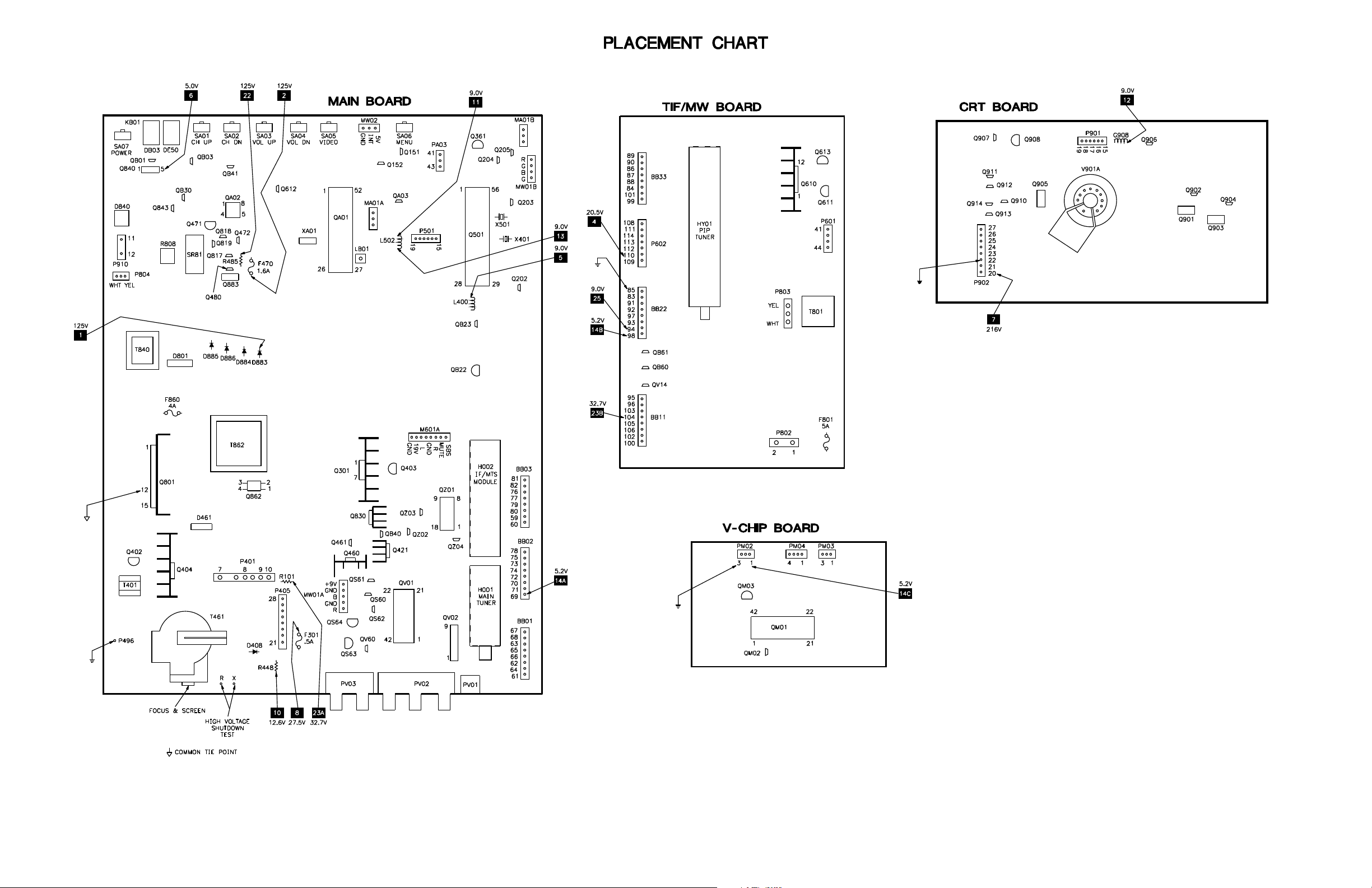
Placement Chart ....................................... 1
Safety Precautions .................................... 1
Schematic Component Location ..............3
Schematic Notes ....................................... 2
Schematics
A/V Switching ................................... 3
CRT ................................................... 2
PIP Control ........................................ 2
Power Supply .................................... 2
System Control .................................. 4
Television .......................................... 2
Test Equipment ......................................... 1
Tuner Information ....................................1
5266
Technical Service Data
TOSHIBA
Model CZ36V61 (Chassis TAC9922)
Representative Model
Essential coverage
for servicing a television receiver...
Schematics
5266
HIGH VOLTAGE SHUTDOWN TEST
Apply 120VAC and turn receiver on. Set all digital customer controls for normal operation. Momentarily
short test point X to test point R. Receiver should lose raster and sound. If the receiver does not lose raster
and sound, the shutdown circuit should be repaired. To resume normal operation, remove AC power and
wait 30 seconds. After restoring AC power, the receiver should power up automatically.
The listing of any available replacement part herein in no case constitutes a recommendation, warranty, or guarantee by
SAMS Technical Publishing, LLC as to the quality and suitability of such replacement part. The numbers of the listed parts
have been compiled from information furnished to SAMS Technical Publishing, LLC by the manufacturers of the specific
type of replacement part listed.
Reproduction or use, without express permission, of editorial or pictorial content, in any manner, is prohibited. No patent
liability is assumed with respect to the use of the information contained herein.
© 2007 SAMS Technical Publishing, LLC
9850 E. 30th St.
Indianapolis IN 46229
www.samswebsite.com
Printed in the United States of America 5 4 3 2 1 07PF03377
Page 1 SET 5266
!IBCGC|05266S
MODEL CZ36V61 (CHASSIS TAC9922)
TOSHIBA
For a Complete List of Manuals,
Visit www.samswebsite.com
Component locations
Parts list
Coverage includes this additional model and chassis:
Model Chassis
CZ32V61 TAC9920
JUNE 2007 SET 5266
3
Page 2
Page 1 SET 5266
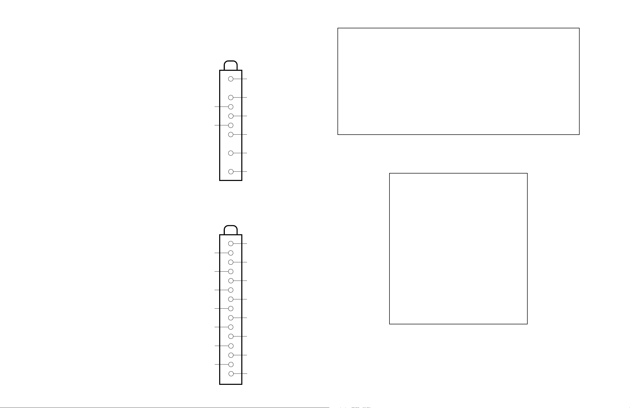
TUNER INFORMATION
Important Parts Information
MAIN TUNER VOLTAGE CHART
Pin VHF Low Band VHF High Band UHF Band
1 (AGC) 1.7V 1.7V 1.6V
3 (A) 4.6V 4.6V 4.6V
4 (SCL) 4.3V 4.3V 4.3V
5 (SDA) 4.3V 4.3V 4.3V
6 (MB) 0V 0V 0V
7 (+5V) 5.0V 5.0V 5.0V
9 (+32V) 32.7V 32.7V 32.7V
11 (IF) 0V 0V 0V
NOTE: VHF Low Band voltages taken on channel 2.
VHF High Band voltages taken on channel 7.
UHF Band voltages taken on channel 14.
PIP TUNER VOLTAGE CHART
Pin VHF Low Band VHF High Band UHF Band
1 (NC) 0V 0V 0V
2 (+32V) 32.7V 32.7V 32.7V
3 (SCL) 4.4V 4.4V 4.4V
4 (SDA) 4.3V 4.3V 4.3V
5 (NC) 0V 0V 0V
6 (ADS) 0V 0V 0V
7 (+5V) 5.0V 5.0V 5.0V
8 (AGC) 3.4V 3.6V 3.2V
9 (9V) 8.7V 8.7V 8.7V
10 (A OUT) 0V 0V 0V
11 (GND) 0V 0V 0V
12 (AFT) 1.8V 1.8V 2.0V
13 (NC) 0V 0V 0V
14 (GND) 0V 0V 0V
15 (V OUT) 4.4V 4.4V 4.4V
NOTE: VHF Low Band voltages taken on channel 2.
VHF High Band voltages taken on channel 7.
UHF Band voltages taken on channel 14.
MAIN TUNER TERMINAL GUIDE
(1)
(3)
(4)
(5)
(6)
(7)
(9)
(11)
PIP TUNER TERMINAL GUIDE
(1)
(2)
(3)
(4)
(5)
(6)
(7)
(8)
(9)
(10)
n Parts not listed in the parts list are commonly available at your local electronics parts retailer.
n The parts listed here are those not usually available from a well-stocked supply cabinet or bin.
n On the parts lists, safety items are marked with a # to remind you that only exact replacements are recommended for
these items.
n When ordering parts, state the model number, part number, and description.
Obtaining Parts
Many of these parts are available from your local Sams authorized distributor or the manufacturer of the equipment. Call
Sams for the name of your nearest distributor:
800-428-7267
TEST EQUIPMENT
Test equipment listed by participating manufacturer illustrates typical or
equivalent equipment used by Sams engineers to obtain measurements.
This equipment is compatible with most types used by field service
technicians.
Equipment Sencore No.
Oscilloscope SC3100
Generators
RGB CM2125
Multiburst Signal VG91
Color Bar VG91
TV Stereo VG91
Digital VOM SC3100
Frequency Meter SC3100
Hi-Voltage Probe HP200
Accessory Probes TP212
Isolation Transformer PR570
Capacitance Analyzer LC102
CRT Analyzer CR7000
AC Leakage Tester PR570
Inductance Analyzer LC102
Flyback Yoke Tester TVA92
Field Strength Meter SL753
Transistor Tester TF46
Horizontal Analyzer HA-2500
Video Analyzer VG91, TVA92
(12)
(14)
(11)
(13)
(15)
Page 3

MISCELLANEOUS ADJUSTMENTS
SET 5266 Page 1
HIGH VOLTAGE CHECK
Tune in a picture. Set brightness, contrast, and color to minimum. Connect a high
voltage probe to the CRT anode. Model CZ32V61: high voltage should read 31kV
to 32.4kV. Model CZ36V61: high voltage should read 31.9kV to 33.3kV.
ENTERING THE SERVICE AND DESIGN MODES
To enter the service mode, press the mute button on the remote. Press the mute
button again and keep pressing while simultaneously pressing the menu button on
the receiver. The letter S will appear on the screen indicating that the receiver is in
the service mode.
To enter the design mode, enter the service mode and press and hold the recall
button while simultaneously pressing the menu button on the receiver. The letter D
will appear on the screen indicating that the receiver is in the design mode. No
items are to be adjusted according to the manufacturer. No information available
for option codes.
When in the service mode or design mode, press the menu button on the receiver to
display the adjustment menu. To select the item to be adjusted, press the channel up
or down button. To adjust the reference value, press the volume up or down button.
To exit from the service mode or the design mode, press the power button to turn
off the receiver.
TEST SIGNAL SELECTION
Enter the service mode. Press the menu button on the receiver to display the
adjustment menu. Press the TV/video button on the remote to display the built-in
test patterns in the following order:
Normal picture, red raster, green raster, blue raster, black screen, white screen,
black screen with white window, black cross bar, white cross bar, black crosshatch,
white crosshatch, black crossdot, white crossdot, white h signal, black h signal,
black cross bar on green raster, and back to normal picture. In some models the
audio test signal may not work with the white h signal, black h signal, black cross
bar on green raster test patterns.
NOTE: If a video cable is connected to the video input jack, the built-in test
patterns will not be displayed on the screen.
SELF DIAGNOSTIC FUNCTION
Enter the service mode. Press the 9 button on the remote to check for proper
execution of IC interfacing. The following is an explanation of what is displayed on
screen:
Display Explanation
[SELF CHECK] Self diagnostic function.
No. 23905036 Part number of QA01.
POWER : 000 Operation number of protecting circuit.
000 display is normal.
BUS LINE : OK BUS line check. OK is normal.
SCL-GND indicates a short to ground of
the SCL signal. SDA-GND indicates a
short to ground of the SDA signal.
SCL-SDA indicates a short between
SCL and SDA signals.
BUS CONT : OK Bus line acknowledge check. OK is
normal. A location number is NG.
QA02 NG indicates QA02 is bad.
BLOCK : UV V1 V2 Green display is normal. Cyan display is
QV01 QV01S no check. Red display is NG. UV is TV
mode, V1 is Video 1 mode, and
V2 is Video 2 mode. UV, V1, and V2
may not be used in some models.
To initialize the self diagnostic data, press and hold the recall button on the remote
while simultaneously pressing the channel down button on the receiver.
INITIALIZATION OF QA02
NOTE: QA02 must be initialized after replacement. Do not initialize QA02 unless
it has been replaced.
Enter the service mode. Press and hold the recall button on the remote while
simultaneously pressing the channel up button on the receiver. The initialization of
QA02 is complete. Program channels into memory.
ITEM BUTTONS
The following is a list of the buttons on the remote that will go to an item or
perform a different function of the service mode:
1 RCUT 5 COLC
2 GCUT 6 TNTC
3 BCUT 8 Toggles audio test signal on and off.
4 SCNT 9 Self diagnostics
SUB COLOR (COLC) & SUB TINT (TNTC)
Tune in a color bar pattern. Set contrast to maximum and brightness to midrange.
Connect an oscilloscope to the red cathode. Enter the service mode. Select item
COLC and adjust reference value to obtain 150Vp-p. Tune in an active channel.
Select item TNTC and adjust reference value for proper flesh tones.
SUB BRIGHTNESS (BRTC)
Tune in a picture. Set contrast to minimim and brightness to center. Enter the
service mode. Select item BRTC, adjust reference value until vertical retrace line
just disappears. Adjust contrast for normal picture. Perform Height (HIT)
adjustment.
HORIZONTAL POSITION (HPOS) /
VERTICAL POSITION (VPOS)
Enter the service mode. Press the TV/video button on remote until a crossbar
pattern is displayed. Select item HPOS or VPOS and adjust reference value for the
horizontal and vertical position alternately until the pattern is centered on the
screen. Check the position of the picture with off-air signal.
HEIGHT (HIT)
Enter the service mode. Press the TV/video button on remote until a crosshatch
pattern is displayed. Select item HIT and adjust reference value for slight
underscan. Advance the data value by 9 steps and check the vertical position of the
picture.
WIDTH (WID)
Enter the service mode. Press the TV/video button on reme until a crosshatch
pattern is displayed. Select item WID, adjust reference value for slight underscan.
Advance the reference value by 7 steps. Check for proper horizontal position of the
picture.
E-W PARABOLA (DPC)
Enter the service mode. Press the TV/video button on remote until a crosshatch
pattern is displayed. Select item DPC, adjust reference value for straight vertical
lines on both sides of the pattern.
WHITE BALANCE (RCUT, GCUT, BCUT, GDRV, BDRV)
Turn receiver on. Allow a 10 to 30 minute warm up time. Adjust contrast to center
and brightness to maximum. Enter the service mode. Press the TV/video button on
remote until the white screen pattern is displayed. Select items RCUT, GCUT,
BCUT, GDRV, and BDRV and set the reference value for each to 40H. Press the
TV/video button on the receiver to obtain a single horizontal line. Advance the
screen control until a faint line of one predominant color appears on the screen.
Adjust the other two cutoff items to obtain a dim white line. Press the TV/video
button on the receiver to get full deflection. Select items GDRV and BDRV and
adjust reference value of each for the best black and white picture on screen.
COLOR PURITY / CONVERGENCE
The yoke is bonded to the CRT. Color purity and convergence adjustments are not
recommended.
STEREO
Enter the service mode.
Attenuator (ATT)
Select item ATT. Input a 1kHz, 30% modulated signal. Connect a RMS meter to
pin 12 of H002. Adjust reference value to obtain a reading of 130mVrms.
Stereo VCO (STVC)
Select item STVC. Connect a frequency counter to pin 12 of H002 and connect pin
9 to ground. Adjust reference value to obtain a reading of 62.936kHz.
SAP VCO (SAVC)
Select item SAVC. Input 78.67kHz, 147mVrms to pin 9 of H002. Input a mono
signal. Adjust reference value for a reading in the center of the range for STA7=0
and STA8=1.
Stereo Filter (STRF)
Select item STRF. Input 9.4kHz, 600mVrms to pin 9 of H002. Input a mono signal.
Adjust reference value for a reading in the center of the range for STA3=1.
SAP Filter (SAPF)
Select item SAPF. Input 88kHz, 110mVrms to pin 9 of H002. Input a mono signal.
Adjust reference value for a reading in the center of the range for STA4=1.
Stereo Separation (WBAN) / Spectral (SPEC)
Select item WBAN. Input 300Hz, right channel signal. Select stereo mode on
receiver. Connect an oscilloscope to pin 14 of H002. Adjust reference value for
minimum amplitude of waveform. Select item SPEC. Input 3kHz, right channel
signal. Adjust reference value for minimum amplitude of waveform.
Audio Test Signal
Enter the service mode. Press the 8 button on remote transmitter to toggle the audio
test signal (1kHz) on and off.
SERVICE MODE ADJUSTMENT CHART
Adjustment Direct Preset 32 36
Item Name Button Value Value Value
RCUT Red Cutoff 1 40H 40H 40H
GCUT Green Cutoff 2 40H 40H 40H
BCUT Blue Cutoff 3 40H 40H 40H
GDRV Green Drive - 40H 40H 40H
BDRV Blue Drive - 40H 40H 40H
SCNT Sub Contrast 4 08H 08H 08H
BRTC Sub Brightness - 40H 40H 40H
COLC Sub Color 5 40H 40H 40H
TNTC Sub Tint 6 40H 40H 40H
SAVC SAP VCO - 88H 88H 88H
ATT Attenuator - 08H 08H 08H
SAPF SAP Filter - 88H 88H 88H
STVC Stereo VCO - 1CH 1CH 1CH
STRF Stereo Filter - 16H 16H 16H
SPEC Spectral - 30H 30H 30H
WBAN Stereo Separation - 22H 22H 22H
HPOS Horizontal Position - 16H 16H 16H
VPOS Vertical Position - 03H 03H 03H
HIT Height - 1EH 1EH 1EH
LIN Vertical Linearity - 07H 06H 06H
VSC Vertical S Correction - 01H 04H 04H
VPS Vertical Shift - 1BH 1BH 1BH
VCP Vertical Compensation - 03H 03H 03H
WID Width - 37H 18H 35H
DPC E-W Parabola - 17H 0AH 17H
CNR E-W Corner - 07H 07H 09H
TRAP Trapezium - 0EH 09H 08H
HCP Horizontal Compensation - 00H 00H 00H
VFC Vertical F Correction - 0FH 0FH 0FH
PCOL (1) PIP Color - 08H 08H 08H
PHUE (1) PIP Tint - 00H 00H 00H
DAC - - 03H 03H 03H
PGOF (1) - - 00H 00H 00H
PROF (1) - - 0AH 0AH 0AH
PBOF (1) - - 0AH 0AH 0AH
(1) Adjust to match PIP brightness, white balance, tint, and color to main screen.
Page 4
TOSHIBA MODEL CZ36V61 (CHASSIS TAC9922)
PHILIPS MODEL 32PT5441/37 (CHASSIS L04.1UAA)
SET 5266 Page 1
Page 5

Page 2 SET 5266
Page 6

SET 5266 Page 2
Page 7

Page 2 SET 5266
PHILIPS MODEL 32PT5441/37 (CHASSIS L04.1UAA)
Page 8

TOSHIBA MODEL CZ36V61 (CHASSIS TAC9922)
PHILIPS MODEL 32PT5441/37 (CHASSIS L04.1UAA)
SET 5266 Page 2
Page 9

Page 3 SET 5266
SET 5266 Page 3
Page 10

SCHEMATIC COMPONENT LOCATION GUIDE
C101 C1
C103 D22
C104 B51
C105 B23
C106 B23
C107 D22
C110 D22
C120 B24
C121 B36
C122 B35
C150 B33
C201 D1
C204 C10
C205 E51
C207 A14
C208 C14
C209 B14
C216 C13
C220 D6
C221 B10
C222 B10
C223 B11
C224 B10
C225 B13
C226 C13
C245 C13
C261 B11
C262 B12
C263 B12
C305 D9
C306 E9
C307 D9
C308 D7
C309 D7
C310 D21
C311 D7
C313 D8
C314 D7
C317 D20
C319 D6
C320 D22
C323 D4
C325 D5
C326 D3
C327 D5
C337 D5
C360 C12
C403 D2
C404 D2
C407 D2
C410 C23
C413 E8
C415 E2
C416 E9
C417 E8
C421 D22
C430 C24
C431 C24
C439 E10
C440 E11
C442 D10
C444 E10
C445 E12
C446 D21
C448 A24
C449 D22
C457 E4
C463 E9
C464 E5
C466 E4
C467 E10
C471 E13
C474 E14
C477 D3
C478 E3
C480 D49
C481 C48
C499 E6
C501 B9
C504 C12
C505 C12
C510 E22
C511 E22
C512 C12
C582 C13
C583 C12
C612 D50
C613 D50
C661 C43
C662 B43
C663 C43
C671 B43
C672 B43
C673 B43
C674 C42
C675 B42
C676 B44
C677 C44
C678 B42
C679 B43
C681 B44
C682 B24
C683 C44
C801 A17
C802 A18
C805 B19
C806 A19
C810 B19
C811 B18
C812 A18
C813 B18
C819 C50
C832 E22
C840 C19
C842 C24
C843 D23
C860 B20
C861 C21
C863 B21
C865 A20
C866 C20
C867 B20
C868 A21
C869 B20
C870 B22
C871 B21
C872 C21
C873 B21
C874 C21
C876 A21
C884 A24
C885 B22
C886 C22
C889 B23
C891 C20
C893 A22
C894 B22
C898 C22
C902 D31
C904 B15
C905 C15
C907 C15
C909 D22
C910 D29
C911 D14
C912 D29
C913 E22
C914 E22
C920 D32
C921 D15
C922 D15
CA05 C47
CA06 C47
CA12 D48
CA21 B47
CA22 D46
CA27 B47
CA28 B46
CA29 C23
CA30 C48
CA37 A49
CA39 A49
CA61 D46
CA68 B50
CA69 B50
CB01 A45
CB60 C45
CB61 C45
CB62 C46
CB63 C46
CM15 B26
CM18 A47
CM19 D47
CM33 B26
CM40 A26
CM41 A26
CM42 B27
CM43 B27
CM44 E23
CM60 D46
CM70 A25
CM71 A26
CM72 A25
CM73 E24
CR01 B13
CR02 B13
CR03 B12
CS02 E37
CS04 E37
CS08 D36
CS10 E36
CS14 D36
CS16 D36
CS25 D36
CS26 D36
CS27 C8
CS32 C38
CS33 B38
CS40 C37
CS42 C37
CS43 E37
CS44 E37
CS45 D37
CS46 E37
CS47 D37
CS48 D37
CS49 D36
CS50 D36
CS51 C37
CS52 C37
CS70 D38
CS71 E38
CV01 A4
CV03 B4
CV05 A3
CV07 A37
CV09 C37
CV11 B3
CV13 C2
CV29 B7
CV31 B7
CV36 C3
CV38 A38
CV39 A38
CV41 B2
CV45 B36
CV46 B36
CV47 B36
CV48 A36
CV49 A36
CV60 A4
CV61 A5
CZ01 B5
CZ02 B6
CZ03 B5
CZ04 B6
CZ05 B6
CZ07 B5
CZ08 B5
CZ09 B5
CZ11 C6
CZ12 C6
CZ13 B5
CZ14 B6
CZ15 B7
CZ16 B7
CZ17 E22
CZ18 C4
D101 B24
D201 C13
D221 C13
D222 C13
D223 A10
D224 A10
D252 B13
D253 B14
D301 D7
D302 D20
D308 D7
D309 D8
D310 E8
D313 E3
D314 E2
D315 E2
D316 C12
D406 C21
D408 D20
D409 C23
D411 D6
D421 D21
D422 E21
D430 C24
D441 E1
D461 E10
D464 E4
D466 E4
D467 E5
D471 E13
D472 E14
D473 E15
D480 C49
D611 D49
D612 E50
D801 A19
D830 E21
D840 C19
D845 B17
D862 B21
D864 A21
D873 B21
D875 B21
D876 A21
D881 B19
D882 C19
D883 A22
D884 B22
D885 C22
D886 B22
D898 B20
D899 A17
D901 D29
D902 D14
D903 D14
D904 A30
D905 C30
D906 B30
D911 D13
DA06 E52
DA27 B47
DB03 C50
DB30 C49
DB45 D49
DE50 B49
DM01 B28
DV01 A4
DV03 B3
DV05 A3
DV13 C3
DV27 C8
DV45 B36
F301 D21
F470 A23
F801 A17
F860 A20
G060 B51
G104 D21
G217 E13
G317 C12
G405 E1
G463 E10
G500 E21
G890 B23
G891 C23
G908 E22
G933 D29
H001 C51
H002 A1
H003 A33
HY01 B35
KB01 A45
L105 B51
L111 A35
L112 A35
L113 B35
L114 B36
L301 D8
L400 C24
L441 D10
L442 D10
L461 E5
L462 D10
L501 C12
L502 E21
L805 B19
L806 A19
L861 A20
L862 B21
L883 A22
L884 B22
L885 A23
L886 B22
L888 C22
L901 B19
L902 A31
L903 C31
L904 B31
L910 D15
LA01 B46
LB01 E46
LM02 B28
LM18 A47
LV01 A38
LV02 C7
LV45 B36
LV98 A13
LV99 C13
LZ01 C5
LZ02 B5
LZ03 B5
LZ04 B5
LZ05 B6
LZ11 B4
P801 A17
PV02 A3
PV02 A5
PV02 C2
PV02 D36
PV02 D36
PV02 D40
PV02 E36
PV02 E36
PV02 E40
PV03 A14
PV03 C13
PV03 C35
PV03 D36
PV03 E36
PV04 C7
PV04 D35
PV04 D35
Q151 B33
Q152 B33
Q202 B9
Q203 C5
Q204 E49
Q205 E50
Q301 D7
Q360 E2
Q361 C12
Q402 E8
Q403 C23
Q404 E9
Q421 D21
Q460 E5
Q461 E4
Q471 E14
Q472 E14
Q480 C48
Q501 B11
Q501 D2
Q610 B43
Q611 C42
Q612 D50
Q613 C43
Q801 B20
Q817 C50
Q818 C50
Q819 C50
Q830 E21
Q840 C23
Q843 B17
Q862 B19
Q883 C19
Q901 A30
Q902 A15
Q903 C30
Q904 C15
Q905 B30
Q906 B15
Q907 D15
Q908 D29
Q910 D14
Q911 D15
Q912 D16
Q913 D16
Q914 D16
QA01 A48
QA02 B50
QA03 E51
QB01 B49
QB03 C49
QB22 C2
QB23 D45
QB30 C51
QB40 D49
QB41 D45
QB60 C46
QB61 C46
QM01 B27
QM02 A26
QM03 B25
QS60 D38
QS61 E38
QS62 E39
QS63 D39
QS64 E39
QV01 B3
QV01 B37
QV01 B8
QV02 B37
QV14 A38
QV60 A4
QZ01 B5
QZ02 B7
QZ03 B7
QZ04 B4
R E13
R101 B23
R102 A52
R151 B33
R152 B33
R201 B9
R202 B9
R203 C10
R207 A14
R208 C14
R209 B14
R216 D13
R223 B9
R228 E13
R238 E50
R239 E51
R240 E50
R241 E50
R245 C13
R261 B11
R262 B11
R263 B12
R264 B11
R265 B12
R266 B12
R271 C5
R272 C5
R275 E49
R301 D7
R303 D8
R304 D9
R305 E9
R306 D9
R307 D9
R308 E11
R309 D8
R310 E8
R311 E8
R313 D9
R314 E3
R315 E3
R317 D6
R327 D21
R328 E3
R336 D9
R360 D3
R361 E3
R363 E2
R364 E2
R368 C12
R369 C12
R401 D4
R403 D2
R405 E1
R406 D2
R407 D1
R408 C23
R410 E6
R411 E6
R415 E8
R416 E9
R418 C23
R424 D20
R425 D20
R430 E12
R431 E14
R432 E15
R433 C4
R441 D10
R448 D20
R456 E1
R457 E4
R460 E5
R461 E5
R462 E4
R463 E5
R464 E4
R465 E6
R466 E5
R472 E13
R473 D3
R474 D2
R475 E13
R476 E13
R477 E13
R478 E13
R481 E14
R482 E13
R485 A23
R486 D49
R487 C48
R488 C49
R489 D49
R490 C49
R501 C12
R502 C11
R503 C11
R511 B9
R512 B9
R612 D50
R613 D50
R614 D50
R661 C42
R662 B42
R663 C43
R664 B43
R667 C42
R668 C42
R669 C43
R676 B44
R677 C44
R808 A19
R810 A19
R816 C50
R818 D50
R819 C50
R830 E20
R831 E21
R861 A20
R862 B21
R864 B20
R866 B19
R867 C20
R868 C21
R870 B19
R871 A21
R872 B20
R883 B19
R884 C19
R889 B23
R891 C20
R898 A17
R901 A31
R902 C31
R903 B31
R904 D30
R905 D30
R911 D13
R914 A15
R915 B15
R917 B15
R918 B15
R920 A31
R921 C15
R922 C15
R924 C15
R925 C15
R928 B15
R929 B15
R930 C15
R932 D14
R934 D14
R935 D14
R936 D29
R937 B15
R939 D15
R942 A31
R943 C31
R944 B31
R960 B31
R961 C31
R962 B31
R977 B15
R980 D14
R981 D15
R982 D15
R983 D15
R984 D16
R985 D16
R986 D16
R987 D16
R988 D15
R989 D16
R990 D16
R991 D15
RA01 D47
RA02 D46
RA03 B47
RA04 E47
RA05 C47
RA06 C47
RA07 B47
RA08 C47
RA09 B47
RA10 B48
RA11 C48
RA12 D49
RA14 C49
RA15 A47
RA16 E48
RA17 B48
RA20 C47
RA22 D46
RA23 D46
RA30 C49
RA31 D49
RA32 B49
RA37 A49
RA39 A49
RA40 B48
RA42 E49
RA43 D48
RA44 C48
RA46 E48
RA47 D50
RA49 E52
RA50 E51
RA51 A12
RA52 A11
RA61 B50
RA62 B48
RA67 A50
RA68 A50
RA70 B47
RA71 B45
RA72 B45
RA73 B46
RA74 B47
RA80 B45
RA81 B45
RA82 B45
RB01 B49
RB03 B50
RB09 A45
RB11 B49
RB21 C2
RB22 C2
RB23 C3
RB24 D46
RB25 D45
RB30 C50
RB40 A48
RB41 A49
RB42 A48
RB43 D48
RB44 D48
RB45 D49
RB46 D48
RB47 D45
RB48 D45
RB49 D46
RB60 C45
RB61 C45
RB62 C46
RB63 C46
RB64 C46
RB65 C47
RG02 B50
RG03 B50
RM19 D46
RM25 B26
RM27 B27
RM33 B26
RM35 A27
RM36 A27
RM37 D26
RM38 C26
RM40 A26
RM41 A26
RM70 A25
RM71 A25
RM72 A25
RM73 A26
RR01 B13
RR03 B13
RR05 B12
RR07 A10
RR08 B11
RR93 B11
RS02 E37
RS04 E37
RS08 D37
RS10 E37
RS14 D37
RS16 D37
RS25 D36
RS26 D36
RS28 E38
RS40 C37
RS42 C37
RS60 D38
RS61 D38
RS62 E38
RS63 E38
RS64 D39
RS65 E39
RS66 E38
RS68 E39
RS69 E39
RS70 D40
RS71 E40
RV01 A4
RV02 A3
RV03 C2
RV04 A3
RV05 C7
RV07 B3
RV08 B3
RV17 A38
RV18 A39
RV19 C36
RV20 B34
RV60 B4
RV61 A4
RV62 A5
RV63 A5
RW01 C36
RW02 C13
RW03 A14
RZ01 B6
RZ02 B7
RZ03 B7
RZ04 B7
RZ05 C6
RZ07 B4
RZ08 B5
RZ09 B4
SA01 B46
SA02 B45
SA03 B45
SA04 B45
SA05 B45
SA06 B45
SA07 B46
SR81 A18
SR81 B17
T401 E9
T461 D11
T461 D19
T801 A18
T840 C18
T862 A22
V901 C32
W661 C44
W662 B44
X E13
X401 D4
X501 C12
XA01 E47
XM01 C26
TOSHIBA MODEL CZ36V61 (CHASSIS TAC9922)
Page 3 SET 5266
PHILIPS MODEL 32PT5441/37 (CHASSIS L04.1UAA)
SET 5266 Page 3
Page 11

Page 4 SET 5266
SET 5266 Page 4
Page 12

PARTS LIST
Item No. Type No. Mfr. Part No. Notes
D101 HTZ33-12 - D201 1SS133 23118859 D221 Thru
D224 1SS133 23118859 D252, 53 MTZJ9.1A 23316686 D301, 02 ERB44-06 23118095 D308, 09 ERB12-02 23118822 D310, 13, 14, 15 1SS133 23118859 D316 (1) MTZJ6.8C 23316679 D316 (2) MTZJ5.6C 23316673 D406 EU2A 23118094 D408 3JH41 A7580658 D409 MTZJ10B 23316690 D411 MTZJ8.2B 23316684 D421 MTZJ4.7A 23316665 D422 MTZJ5.1B 23316669 D430 MTZJ12C 23316720 D441 MTZJ9.1B 23316687 D461 ERC20-06 23316582 D464 MTZJ2.2A 23316648 D466 MTZJ2.7B 23316653 D467, 71 ERB44-06 23118095 -
# D472 RD6.2E(4) 23115774 -
D473 1SS133 23118859 D480 MTZJ36A 23316757 D611, 12 1SS133 23118859 D801 D3SB60 23316391 D830 MTZJ5.6C 23316673 D840 S1WBA20 23316962 D845 1SS133 23118859 D862 EU2A 23118094 D864 EU2A 23118094 D873, 75 MTZJ12B 23316719 D876 MTZJ39B 23316761 D881 1SS133 23118859 -
# D882 MTZJ13A 23316721 -
D883, 84 EL1 23357021 D885, 86 EU2A 23118094 D898 MTZJ27B 23316746 D899 TNR10V271K2 24019471 D901 Thru
D906 1SS133 23118859 D911 ERB44-06 23118095 DA06 1SS133 23118859 DA27 MTZJ5.6B 23316672 DB03 SIR-56SB3F 23358522 DB30, 45 1SS133 23118859 DE50 SCL003URC5F 23358501 DM01 MTZJ6.2B 23316675 DV01, 03, 05 MTZJ9.1A 23316686 DV13, 27, 45 MTZJ9.1A 23316686 G317 1SS133 23118859 Q151 2SA933S-Q 23114530 Q152 2SC1740S-Q 23114528 Q202, 03 2SC1740S-Q 23114528 Q204, 05 RN1204 A6002040 Q301 TA8427K B0378560 Q360 2SC1740S-Q 23114528 Q361 2SC4721-Q 23314445 Q402 2SC2482FA-1 A6330069 Q403 2SC4721P 23314444 Q404 2SD2553 A6873777 Q421 2SC3852 23314141 Q460 2SD2493(D) 23314938 Q461 2SA933S-Q 23114530 Q471 2SA1015-0 A6534020 Q472 2SC1740S-Q 23114528 Q480 2SA949-Y(C) A6532853 Q501 TA1310AN - Q610 TA8211AH B0376856 Q611 2SC2878-A A6342200 Q612 KTA1266Y 23314962 Q613 2SC2878-A A6342200 Q801 STR-Z4214 23906369 Q817 2SC1740S-Q 23114528 Q818 RN2201 A6012010 Q819 2SC1740S-Q 23114528 Q830 2SC3852 23314141 Q840 L78MR05 23318299 Q843 RN1205 A6002050 Q862 TLP621(GRL) A8643135 -
# Q883 S1854(FA4) A6907894 -
Q901 2SC4544 A6368700 Q902 2SC1740S-Q 23114528 -
Page 4 SET 5266
Item No. Type No. Mfr. Part No. Notes Item No. Function/Rating Mfr. Part No. Notes
Q903 2SC4544 A6368700 Q904 2SC1740S-Q 23114528 Q905 2SC4544 A6368700 Q906 2SC1740S-Q 23114528 Q907 2SA933S-Q 23114530 Q908 2SC2120-Y A6321240 Q910, 11 2SC1740S-Q 23114528 Q912, 13 2SA933S-Q 23114530 Q914 2SC1740S-Q 23114528 QA01 M37274EF-052 23906893 QA02 24LC08BI/P 23905036 QA03 2SC1740S-Q 23114528 QB01 2SC1740S-Q 23114528 QB03 RN1205 A6002050 QB22 2SC725(G)TM-Y A6734590 QB23, 30, 40, 41 2SC1740S-Q 23114528 QB60 2SA933S-Q 23114530 QB61 2SC1740S-Q 23114528 QM01 TMPA8700CHN-150 23906920 QM02 2SA933S-Q 23114530 QM03 PST523D 70119743 QS60, 61 2SC1740S-Q 23114528 QS62 RN2204 A6012040 QS63, 64 2SC2878-A(TE) A6342206 QV01 MM1313BD 23906364 QV02 MM1111XS 23904943 QV14 2SA933S-Q 23114530 QV60 2SC1740S-Q 23114528 QZ01 TC90A45P B0410867 QZ02, 03, 04 2SC1740S-Q 23114528 -
Item No. Function/Rating Mfr. Part No. Notes
C305 (1) 2.2µF 10% 50V 24617912 C305 (2) 1µF 10% 50V 24617915 C327 1µF 10% 50V 24617915 -
# C440 (1) .008 3% 1.5kV 24082959 -
# C440 (2) .0078 3% 1.5kV 24082958 -
# C442 (1) .43 5% 315V 24082921 -
# C442 (2) .39 5% 315V 24082920 -
# C444 (1) .0056 3% 1.8kV 24082610 -
# C444 (2) .0062 3% 1.8kV 24082611 -
# C467 (1) .015 3% 630V 24095883 -
# C467 (2) .018 3% 630V 24095881 -
C505 12pF 5% 50V NPO 24353120 C801 .22 20% 125VAC 24095670 C802 .082 20% 125VAC 24095852 C805, 06 .01 +80% -20% 250VAC 24092623 C811, 12 .0047 20% 250VAC 24092585 C813 .01 20% 250VAC 24092586 C865, 71 .0015 10% 2kV 24092347 C893, 94 100pF 10% 2kV 24092333 C902 .001 10% 2kV 24092345 CB60 2.2µF 20% 50V NP 24085944 CM70 10µF 20% 16V NP 24085981 F301 Fuse 23144908 .5Amp, 125V, Fast Acting
F470 Fuse 23144731 1.6Amp, 125V, Fast Acting
F801 Fuse 23144888 5Amp, 125V Fast Acting
F860 Fuse 23144511 4Amp, 125V
G104 - 23289470 G463 Ferrite Bead 23103880 G500 - 23289840 G890, 91 - 23280016 G908 - 23289100 H001 Tuner 23321332 Main, ELA22LX2
H002 Module 23148271 IF/MTS, MVUS33A
H003 RF Switch 23344420 RSU133X5
HY01 (1) Tuner 23321327 PIP, EL934L3
KB01 Receiver 23906805 Remote, PIC-TB17
L105 - 23289220 L111, 12 - 23238562 L113, 14 - 23289220 L301 Ferrite Bead 23103880 L400 - 23238714 -
# L441 (1) Horizontal Linearity 23233979 -
# L441 (2) Horizontal Linearity 23233941 -
L442 (1) - 23248121 L442 (2) - 23248122 -
# L461 (1) - 23248179 -
# L461 (2) - 23248115 -
# L462 (3) Yoke - -
L501, 02 - 23289844 L805, 06 - 23248227 L861, 62 Ferrite Bead 23103880 -
L883, 84 Ferrite Bead 23103880 L885 - 23248073 L886, 88 Ferrite Bead 23103880 L901 (1) Degaussing 23200335 L901 (2) Degaussing 23200631 L902, 03, 04 - 23289221 L910 - 23237991 LA01 - 23289100 LB01 Oscillator 23262261 LM02 - 23289840 LM18 - 23289100 LV01 - 23289840 LV02 - 23103852 LV45 - 23289840 LV98, 99 Filter 23103852 LZ01 - 23238708 LZ02 Ferrite Bead 23103880 LZ03 - 23238714 LZ04 Ferrite Bead 23103880 LZ05 - 23289840 LZ11 - 23289836 P801 Line Cord 23372070 AC, Polarized
PV01 Socket 23365818 SVHS
PV02 Jack 23365948 Assembly
PV03 Jack 23365949 Assembly
PV04 Jack - Assembly
R368 4.7 1/4W Fusible 24545479 R416 (1) 4300 5W 24019332 R416 (2) 4300 5W 24510432 R424 .82 1/2W Fusible 24546828 R441 1000 1W Fusible 24532102 -
# R475 390 24366391 -
# R478 13K 1% 1/4W 24327133 -
# R482 4700 1% 1/4W 24327472 -
R488, 89 18K 1% 1/4W 24327183 R808 PTC 24000862 R810 .82 10% 10W 24569828 R889 .39 1/2W Fusible 24546398 R920 (1) 2.2 1W Fusible 24000961 R920 (2) 5.1 1W Fusible 24000880 R984 1500 2% 24367152 R985 470 2% 24367471 R986, 87 680 2% 24367681 R988, 89 4700 2% 24367472 R991 680 2% 24367681 SA01 Switch 23145227 Channel Up
SA02 Switch 23145227 Channel Down
SA03 Switch 23145227 Volume Up
SA04 Switch 23145227 Volume Down
SA05 Switch 23145227 Video
SA06 Switch 23145227 Menu
SA07 Switch 23145227 Power
SR81 Relay 23146564 Power
T401 Horizontal Drive 23224367 -
# T461 (4) Horizontal Output 23236540 -
T801 Line Filter 23211708 T840 Power 23213513 T862 Converter 23217379 -
# V901 (1) CRT 23312713 A90AHH50X02V
# V901 (2) CRT 23312690 A81AGZ50X01V
# V901A Socket 23902068 CRT
W661, 62 Speaker 23351088 2 1/4" X 5", 8 Ohms, 5W
X401 Crystal 23153721 503kHz
X501 Crystal 23153961 3.58MHz
XA01 Crystal 23153504 8MHz
XM01 Resonator 23153325 8MHz
ZY01 Module 23148353 PIP
# For SAFETY use only equivalent replacement part.
(1) Used in model CZ36V61.
(2) Used in model CZ32V61.
(3) Bonded part of CRT.
(4) Screen and focus controls are part of T461.
Fuse Holder 23165433 For F301, F470, and
PC Board (1) - CRT, PB8642B
PC Board (2) - CRT, PB8642A
PC Board (1) - Main, PB8643C
PC Board (2) - Main PB8643A
PC Board - TIF/MW, PB8644A
PC Board - V-Chip, PB8688A
Transmitter 23306267 Remote
TOSHIBA MODEL CZ36V61 (CHASSIS TAC9922)
F801 (2 Used, Each)
SET 5266 Page 4
 Loading...