

Page 1

CX506a
MULTITESTER
取扱説明書
INSTRUCTIONMANUAL
Page 2

Page 3
目 次
安全に関する項目〜ご使用前に必ずお読みください〜
【1】
……001
1−1 安全使用のための警告文 …………………………………001
1−2 電磁界、静電界などの影響 ………………………………002
1−3 警告マークなどの記号説明 ………………………………002
1−4 最大過負荷保護入力値 ……………………………………002
【2】用途と特長 ………………………………………………………003
2−1 用 途 ………………………………………………………003
2−2 特 長 ………………………………………………………003
【3】各部の名称 ………………………………………………………003
【4】指示の読み取り方 ………………………………………………004
【5】機能説明 …………………………………………………………005
5−1 スイッチ・調整器 …………………………………………005
5−2 スタンドの使い方 …………………………………………005
【6】測定方法 …………………………………………………………006
6−1 始業点検 ……………………………………………………006
6−2 レンジの設定方法(最適レンジの設定) ………………006
6−3 測定前の準備 ………………………………………………006
6−4 電圧(V)測定 ……………………………………………008
6−4−1 直流電圧(DCV )測定 …………………………008
6−4−2 交流電圧(ACV〜 )測定 …………………………009
6−5 直流電流(DCA )測定 ………………………………010
6−6 抵抗(Ω)測定 ……………………………………………011
6−7 静電容量( )測定 ……………………………………013
6−7−1 C1、C2レンジでの測定 ……………………………013
6−7−2 C3レンジでの測定 …………………………………015
6−8 トランジスタの測定 ………………………………………016
6−8−1 I
6−8−2 直流電流増幅率(h
6−9
10
6−
CEO(漏洩電流)の測定……………………………016
FE)の測定 ……………………017
高圧プローブ(HV-50)による直流高電圧(HV)の測定(別売品)
……018
測定の終了 …………………………………………………018
Page 4

【7】保守管理について ………………………………………………019
7−1 保守点検 ……………………………………………………019
7−2 校正点検 ……………………………………………………019
7−3 内蔵電池・ヒューズの交換 ………………………………019
7−4 清掃と保管について ………………………………………021
【8】アフターサービス ………………………………………………021
8−1 保証期間について …………………………………………021
8−2 修理について ………………………………………………021
8−3 お問い合わせ ………………………………………………022
【9】仕 様 ……………………………………………………………023
9−1 一般仕様 ……………………………………………………023
9−2 別売付属品 …………………………………………………023
9−3 測定範囲および許容差 ……………………………………024
保証書 …………………… 最終ページにあります。
Page 5

CONTENTS
SAFETY PRECAUTIONS:Before use, read the following safety precautions
[1]
……025
1-1 Warning Instruction for safe use …………………………025
1-2 Explanation of Warning Symbols …………………………026
1-3 Overload Protections ………………………………………026
1-4 Influence of the electromagnetic field ……………………026
[2] APPLICATION AND FEATURES……………………………027
2-1 Application …………………………………………………027
2-2 Features ……………………………………………………027
[3] NAME OF FUNCTIONS ………………………………………027
[4] SCALE READING ……………………………………………028
[5] DESCRIPTION OF FUNCTIONS ……………………………029
5-1 Selections, adjusters and switches ………………………029
5-2 How to Use the Stand ……………………………………029
[6] MEASUREMENT PROCEDURE ……………………………030
6-1 Start -up Inspection…………………………………………030
6-2 How to select an appropriate range ………………………030
(Selection of an appropriate range)
6-3 Preparation for Measurement ……………………………030
6-4 Voltage Measurement ……………………………………032
6-4-1 DCV Measurement ( ) ………………………………032
6-4-2 ACV Measurement ( ) ………………………………033
6-5 DCA Measurement ( ) …………………………………034
6-6 Resistance Measurement …………………………………035
6-6-1 Resistance Measurement ( Ω ) ………………………035
6-6-2 Terminal to Terminal Current ( LI )……………………036
6-7 Capacitance Measurement ( ) …………………………037
6-7-1 C1,C2 Range ……………………………………………037
6-7-2 C3 Range ………………………………………………039
6-8 Transistor Measurement …………………………………040
CEO Measurement ……………………………………040
6-8-1 I
Page 6

6-8-2 hFE Measurement …………………………………………041
6-9 DC High Voltage measurement …………………………042
6-10 End of Measurement ………………………………………042
[7] MAINTENANCE ………………………………………………043
7-1 Maintenance and Inspection ………………………………043
7-2 Calibration …………………………………………………043
7-3 How to Replace Battery and Fuse ………………………043
7-4 Cleaning and Storage………………………………………045
[8] AFTER-SALE SERVICE………………………………………045
8-1 Warranty and Provision ……………………………………045
8-2 Repair ………………………………………………………046
8-3 SANWA web site……………………………………………046
[9] SPECIFICATIONS ……………………………………………047
9-1 General Specification ………………………………………047
9-2 Optional Accessories ………………………………………048
9-3 Measurement Range and Accuracy………………………048
Page 7
【1】 安全に関する項目〜ご使用前に必ずお読みください〜
このたびはアナログマルチテスタCX506a型をお買い上げいただき、
誠にありがとうございます。
ご使用前にはこの取扱説明書をよくお読みいただき、正しく安全に
ご使用ください。そして常にご覧いただけるように製品と一緒にして
大切に保管してください。
本文中の 警告および 注意の記載事項は、やけどや感
電などの事故防止のため、必ずお守りください。
1−1 安全使用のための警告文
警 告
以下の項目は、やけどや感電などの人身事故を防止するためのも
のです。本器をご使用する際には必ずお守りください。
なお、取扱説明書での説明以外の使い方をしますと、本器に与えら
れた保護が損なわれることがありますのでご注意ください。
01. 6kVAを超える電力ラインでは使用しないこと。
02. AC33Vrms(46.7Vpeak)またはDC70V以上の電圧は人体に危険な
ため注意すること。
03. 最大定格入力値を超える信号は入力しないこと。
04. 最大過負荷入力値を超えるおそれがあるため、誘起電圧、サー
ジ電圧の発生する(モータ等)ラインの測定はしないこと。
05. 本体またはテストリードが傷んでいたり、壊れている場合は使
用しないこと。
06. リヤケースをはずした状態では使用しないこと。
07. ヒューズは必ず指定定格および仕様のものを使用し、代用品を
用いたり短絡することは絶対にしないこと。
08. 測定中はテストリードのつばよりテストピン側を持たないこと。
09. 測定中は他のファンクションまたは他のレンジに切り換えた
り、プラグを差し換えたりしないこと。
10. 測定ごとのレンジおよびファンクション確認を確実に行うこと。
11. 本器または手が水などでぬれた状態での使用はしないこと。
12. テストリードは指定タイプのものを使用すること。
13. 内蔵電池および内蔵ヒューズ交換を除く修理・改造は行わない
こと。
14. 年 1 回以上の点検は必ず行うこと。
15. 屋内で使用すること。
− 1−
Page 8
1−2 電磁界、静電界などの影響
強力な電磁界、静電界のある場所での測定、インバータなど高調
波を多量に含む回路の測定では誤動作することがあります。
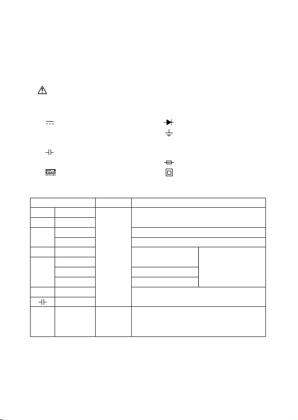
1−3 警告マークなどの記号説明
本器および『取扱説明書』に使用されている記号と意味について
:安全に使用するための特に重要な事項を示します。
警告文はやけどや感電などの人身事故を防止するためのものです。
・
・
注意文は本器を壊すおそれのある取り扱いについての注意文です。
:直流電圧(DCV) :ダイオード
〜 :交流電圧(ACV) :グランド
Ω :抵抗 + :プラス
:静電容量 − :マイナス
hFE:直流増幅率 :ヒューズ
ヒューズとダイオードによる回路保護:二重絶縁または強化絶縁
:
1−4 最大過負荷保護入力値(容量6kVA以内の電路について)
ファンクション(レンジ)
1000
DCV
ACV
750
120/300
DCV
ACV
3/12/30
120mV
DCV
30μ/0.3m
DCA
3m
30m/0.3
×1〜×10k
Ω
C1/C2/C3
h
FE
入力端子 *1 最大過負荷保護入力値
DC・AC1000Vまたは peakmax1400V
DC・AC750Vまたは peakmax1100V
DC・AC200Vまたは peakmax280V
+,−
DC・AC1mA
DC・AC10mA
DC・AC0.5A
*2
DC・AC50Vまたは peakmax75V
・EMITTER
−
・COLLECTOR
DC・AC50Vまたは peakmax75V
*2
DC・AC100V
または
peakmax140V
・BASE
*1 最大過負荷保護入力値の印加時間は5秒以内とする。
また、AC電圧の入力波形は正弦波とする。
*2 過負荷入力が電圧の場合はヒューズ(500mA)とダイオードに
て回路保護をする。ただし、電圧波形の入力の極性とタイミン
グによっては抵抗器なども焼損することがある。
− 2−
Page 9
【2】用途と特長
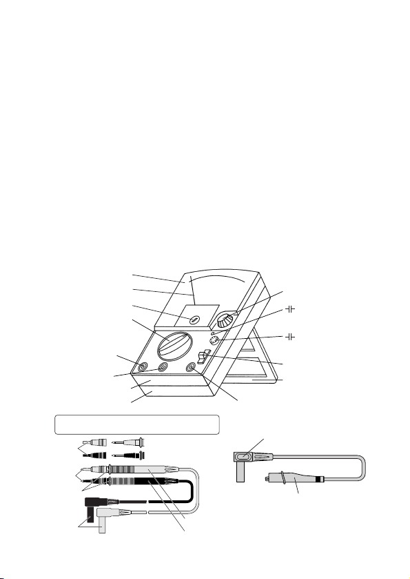
テストピン
つば
プラグ
TL-21a
テストプローブ(赤)
テストプローブ(黒)
着脱式
テストピン
キャップ
未装着時
・着脱式テストピンキャップ装着時:CAT.III600V
・着脱式テストピンキャップ未装着時:CAT.II1000V
2−1 用 途
本器は、小容量電路の測定用に設計された、携帯用アナログマル
チテスタです。小型の通信機器や、家電製品、電灯線電圧や各種電
池の測定などはもちろん、コンデンサの静電容量測定やトランジス
タチェッカとしてもご使用いただけます。
2−2 特 長
● IEC61010-1測定カテゴリⅢ(MAX600V)に準拠
●6ファンクション/26レンジと豊富な機能
●高感度トートバンドメータの採用でDCVは50kΩ/Vと高入力抵抗
●ワイドな静電容量測定機能付き(内蔵発振器、抵抗レンジ使用)
●電源スイッチ固定機能により静電容量の連続測定が可能であり、
電源ON表示ランプで電源のON、OFFが確認できる親切設計
●+、−極性切り換えSW付き(DCVとDCAファンクション)
●簡易トランジスタチェック機能付き
【3】各部の名称
目盛板(スケール板)
メータ指針
メータ0位調整器
ファンクション/レンジ
切り換えスイッチつまみ
(−)入力端子兼
コレクタ接続端子
ベース接続端子
リヤケース
パネル
0Ω・C∞調整器つまみ
ファンクション電源
ON表示ランプ
ファンクション電源用
押しボタンスイッチ
極性切り換えスイッチつまみ
スタンド
(+)入力端子兼エミッタ接続端子
プラグ
わにくちクリップ
わにくちクリップ付き
リード線(CL-506a)
− 3−
Page 10
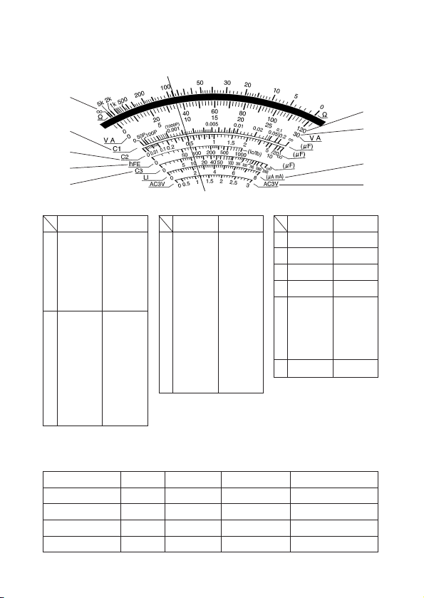
【4】指示の読み取り方
①
④
⑤
⑥
⑦
②
③
⑧
⑨
使用レンジ
Ω×10k
Ω×1k
①
Ω×100
Ω×10
Ω×1
DCV1000
DCV120
DCV12
②
DCV120m
ACV750
ACV120
ACV12
読み取り倍率
×10k
×1k
×100
×10
×1
×10
×1
×0.1
×1
×10
×1
×0.1
注)指示はなるべく指針の真上で読み取って
使用レンジ
DCV300
DCV30
DCV3
ACV300
ACV30
③
DCmA30μ
DCmA0.3
DCmA3
DCmA30
DCmA0.3A
ください。
●上図指針位置での読み取り例
ファンクション
Ω
DCV
ACV
DCmA
レンジ 目盛番号 読み取り方 読み取り結果
×100
120V
3V
3mA
①
②
⑨
③
読み取り倍率
×10
×1
×0.1
×10
×1
×1
×0.01
×0.1
×1
×0.01
− 4−
④
⑤
⑥
⑦
⑧
⑨
89×100
36×100
1.17×100...
.9×0.1
使用レンジ
C1
C2
h
C3
80mA
8mA
800μA
80μA
ACV3
FE
読み取り倍率
×1
×1
×1
×1
×10
×1
×100
×10
×1
8900[Ω]=8.9[kΩ]
36[V]
1.17[V]
0.9[mA]
Page 11

【5】機能説明
5−1 スイッチ・調整器
①ファンクション/レンジ切り換えスイッチ
つまみを回すことによりファンクションおよびそのレンジを切
り換えることができます。
②メータ0位調整器
この調整器を(−)ドライバーで回して、メータの指針を目盛
左端の0位に合わせます。
③0Ω・C∞調整器
抵抗(Ω)、静電容量(C1〜C3)、h
測定前にテストピンをショートしてこのつまみを回し、Ω測定
FE測定はΩ目盛の0に、C1〜C3測定の場合は各C目盛の∞に
とh
メータの指針を合わせます。
④ ファンクション電源用押しボタンスイッチ
静電容量(C1、C2)を測定するときには、このボタンを操作
し、電源をONの状態にして測定します。ボタンを指先で押す
と、電源はON、離すとOFFになります。ボタンを押しながら
右へ約45°回すとボタンは沈んだまま固定され、電源は連続
ONの状態になります。測定終了後は電池の消耗を防ぐため、
必ずボタンを左に回して電源をOFFにします。
⑤ ファンクション電源ON表示ランプ
ファンクションの測定用電源がONのときに点滅します。
⑥極性切り換えスイッチ
DCV、DCAの各ファンクションでの測定時に、極性切り換え
スイッチを切り換えると測定端子の極性の+−が反転します。
従って、メータの指針が逆方向(−方向)に振れたとき、この
スイッチを−側に切り換えることにより、テストリードの接続
を変えずにメータを+方向に振らすことができます。(通常
は+側にしておきます)
FE測定のときに使います。
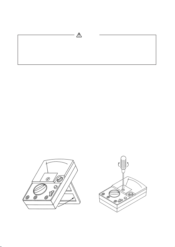
5−2 スタンドの使い方
リヤケースに付いているスタンドは、次ページの図のように、立
てて使用します。
− 5−
Page 12
【6】測定方法
6−1 始業点検(次ページのフローチャートを参照のこと)
警 告
1. 感電防止のため、テスタ本体またはテストリードが損傷して
いる場合は使用しないこと。
2. テストリードまたはヒューズが切れていないことを確認する
こと。
6−2 レンジの設定方法
①電圧(DCV、ACV)、電流(DCA)の最適なレンジの選択
原則として、最大目盛値が測定しようとする値より大きく、し
かもメータがなるべく大きく振れるようなレンジを選びます。
例えば9Vの電圧を測定する場合は3Vや300Vレンジではなく12V
レンジを、15Vを測定する場合は30Vレンジを選択します。
測定値の見当がつかない場合は、最大のレンジ(DCVは1000V、
ACVは750V、DCAは0.3A)で測定してみます。
②抵抗(Ω)の最適レンジの選択
なるべく指示をΩ目盛の中央付近で読み取れるレンジを選択し
ます。
6−3 測定前の準備
0位調整器を回し、メータ指針を目盛板左端の0位置に合わせます。
スタンドの使い方
メータ0位調整
− 6−
Page 13
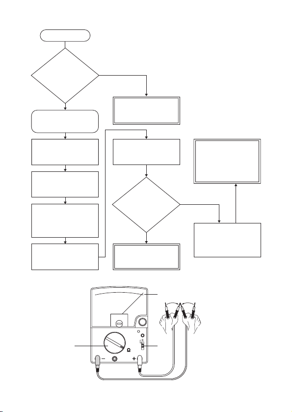
テストリードおよび
ヒューズの断線確認
①黒プラグを−入力
端子に差し込みま
す。
そのまま使用せず、
修理を依頼してくだ
さい。
②赤プラグを+入力
端子に差し込みま
す。
⑤赤、黒のテストピ
ンをショートしま
す。
※内蔵電池が完全に
消耗していても指
針は振れません。
ヒューズまたはテス
トリードを交換して
③からやり直してく
ださい。
④極性切り換えスイ
ッチつまみを+側
に切り換えます。
③ファンクション/
レンジ切り換えつ
まみをΩ×10kレン
ジに合わせます。
点検スタート
本体および
テストリードの
外観が壊れてい
ますか?
⑥指針が
右に大きく振れ
ていますか?
ヒューズまたはテスト
リードを交換してやり
直してみても指針が振
れない場合は、修理を
依頼してください。
異常はありません。
点検終了です。
壊れている
壊れていない
振れている
振れていない
※
③
②①
− 7−
⑥
⑤
④
Page 14
6−4 電圧(V)測定
警 告
1. 各レンジの最大定格入力電圧を超えた入力を加えないこと。
2. 測定中は他のレンジやファンクションに切り換えないこと。
3. 測定値の見当がつかない場合は、最大レンジで測定すること。
4. 測定中はテストリードのつばよりテストピン側を持たないこと。
5. 負荷と並列に接続して測定すること。
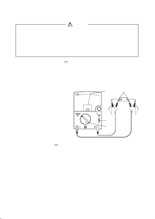
6−4−1 直流電圧(DCV ) 最大測定電圧 DC1000V
1)電池や直流回路の電圧を測ります。
2)測定レンジ
120m/3/12/30/120/300/1000までの7レンジ
3) 測定方法
①極性切り換えスイッ
チは通常+側です。
②テストリードの赤プ
ラグを+入力端子、
⑤
④
⑥⑥
電池
黒プラグを−入力端
子に差し込みます。
③ファンクション/レ
ンジ切り換えスイッ
チつまみ(以後、フ
ァンクション切り換
②
①
③
②
えつまみと言う)
を回してDCV の最適レンジに合わせます。
④被測定回路のマイナス(−)電位側に黒のテストピン、プ
ラス(+)電位側に赤のテストピンを接触させます(負荷
と並列接続)。
⑤V・A目盛にてメータの指示を読み取ります。
⑥測定後は、被測定回路からテストピンをはずします。
●指針が−側(左方向)に振り切れた場合には、極性切り換
えスイッチつまみを−側に切り換えて、−何ボルトと読み
取ります。
●1000Vレンジでは、0〜120の目盛を10倍して読み取ります。
ただし、1000Vを超える電圧測定は絶対にしないでください。
− 8−
Page 15
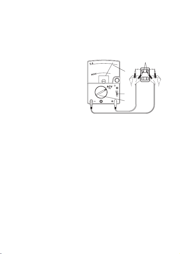
6−4−2 交流電圧(ACV〜)測定 最大測定電圧 AC750V
1)測定対象
主に電灯線回路など、正弦波交流の電圧を測ります。
2)測定レンジ
3/12/30/120/300/750までの6レンジ
3)測定方法
①極性切り換えスイッ
チは+側にします。
②テストリードの赤プ
ラグを+入力端子に、
黒プラグを−入力端
子に差し込みます。
③ファンクション切り
換えつまみを回して
ACV〜の最適なレン
ジに合わせます。
②
②
⑥⑥
⑤
コンセント
①
③
④被測定回路の測定点
に負荷と並列になるよう、赤と黒のテストピンをそれぞれ
接続します。交流は+、−の極性には無関係です。
⑤V・A目盛でメータの指示を読み取ります。
ただし、3VレンジはAC3V目盛で読み取ります。
⑥測定後は、被測定回路からテストピンをはずします。
●正弦波交流以外の交流電圧測定では、波形の歪みに応じた
大きさの誤差を生じます。
●交流の周波数が高くなると誤差が大きくなります。
3、12Vレンジは40Hz〜30kHzの範囲内
30Vレンジ以上では40Hz〜10kHzの範囲内でご使用ください。
●750Vレンジの指示は0〜120の目盛を10倍して読み取りま
す。従って750(75)以上の目盛もあるわけですが、安全上
750Vを超す電圧の測定は絶対にしないでください。
●危険ですから6kVAを超える回路の電圧測定はしないでくだ
さい。
●周波数が数10kHz以上の強力な電磁界のある環境下では誤
動作をすることがあります。
④
− 9−
Page 16
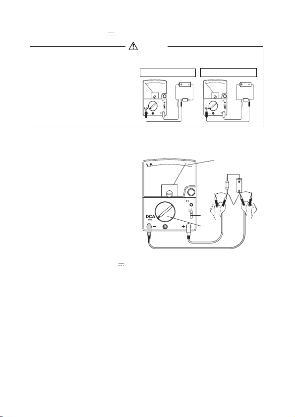
6−5 直流電流(DCA )測定 最大測定電流 DC0.3A
警 告
1. 人体への危険や本器の故障防止上、入力端子に電圧を加えな
いこと。
2. 必ず負荷を通して直列に
接続すること。(右図参照)
3. 入力端子に最大定格電流
○正しい接続(直列)
×危険な接続(並列)
電源
負荷
を超える電流を流さない
こと。
1) 測定対象
電池や直流回路の電流を測ります。
2) 測定レンジ
30μ/0.3m/3m/
30m/0.3(5レンジ)
3) 測定方法
①極性切り換えスイッ
チは通常+側へセッ
トしておきます。
②テストリードの赤プ
ラグを+入力端子に、
②
黒プラグを−入力端
②
子に差し込みます。
③ファンクション切り
換えつまみをDCA の最適レンジに合わせます。
④被測定回路の−電位側に黒のテストピン、+電位側に赤のテス
トピンを直列に接触させます。
⑤V・A目盛にてメータの指示を読み取ります。
⑥測定後は、被測定回路からテストピンをはずします。
●指針が−側(左方向)に振り切れた場合には、極性切り換えス
イッチつまみを−側に切り換え、−何アンペアとして読み取り
ます。
●電流測定では電流レンジの内部抵抗が被測定回路と直列に入
り、その内部抵抗の大きさに応じて、実際の電流より小さくな
ります。
●入力端子に直接電圧を加えたり0.5Aを超える電流を流したりす
ると本器内のヒューズがしゃ断します。
⑤
抵抗器
⑥⑥
④
①
③
電源
負荷
電池
− 10−
Page 17
6−6 抵抗(Ω)測定 最大測定抵抗 50MΩ
警 告
電圧の加わっている部分の抵抗測定をすると、本器の故障の原
因となるばかりではなく、人体へ危険が及ぶことがあります。
1) 測定対象
抵抗器や回路の抵抗測定、部品や回路の導通チェックをします。
2) 測定レンジ
×1/×10/×100/×1k/×10kΩ(5レンジ)
3) 測定方法
①極性切り換えスイッ
チは+側へセットし
ます。
②テストリードの赤プ
ラグを+入力端子
に、黒プラグを−入
力端子に差し込みま
す。
③ファンクション切り
②
⑥
④
抵抗器
⑦⑦
⑤
①
③
②
換えつまみをΩの最
適レンジに合わせます。
④赤と黒のテストピンをショートして、0Ω・C∞調整器つまみを
回し、メータの指針をΩ目盛の0目盛線に合わせます。
⑤赤、黒のテストピンのショートを解き、被測定物につなぎ換え
ます。
⑥Ω目盛にてメータの指示を読み取ります。
⑦測定後は、被測定回路からテストピンをはずします。
●LI(端子間電流)は抵抗測定時の入力端子+、−間に流れる電流
です。本器パネル上、各Ωレンジの右側にLIの最大値が付記さ
れています(80μA、800μA、8mA、80mA)。
×1k レンジの場合はLI目盛を10倍しμA単位で読み取ります。
×100 レンジの場合はLI目盛を100倍しμA単位で読み取ります。
×10 レンジの場合はLI目盛を直接mA単位で読み取ります。
×1 レンジの場合はLI目盛を10倍しmA単位で読み取ります。
− 11−
Page 18

●LEDの発光テスト
本器のΩレンジは3Vで動作させていますので、LEDの発光
テストが行えます。適当なレンジは×10レンジです。
●抵抗レンジの+、−測定端子の極性
本器パネル上の測定端子に付記されている+、−とは逆極
性となります(+測定端子に内蔵電池の−が接続される)。
●ダイオード、トランジスタなど半導体の抵抗測定上の注意
・測定電圧の加わる方向で、その値が大きく変わります。
前項の入力端子の極性に注意してください。
・使用するレンジ(×1/×10…)により抵抗値が変わりま
す。被測定物に流れる電流が使用するレンジにより変わ
るためです。
●端子開放電圧
×1〜×1kレンジ:約3V ×10kレンジ:約12V
●人体の抵抗による影響
テストピンに指を触れて測定すると、人体の抵抗の影響を
受けて誤差を生じます。
特に、×1kレンジと×10kレンジでその影響が大きくなり
ます。
●内蔵ヒューズの抵抗の影響
仕様の項目に記された定格「500mA/250V φ5×20セラミッ
ク管入り速断ヒューズ」と異なるヒューズを使用すると、
その抵抗値の違いにより、×1レンジで0Ω調整ができなく
なったり誤差を生じたりすることがあります。必ず同定格
のヒューズを使用してください。
●測定電流の影響
電球のフィラメントや極細線のコイル、また半導体の抵抗
は、抵抗測定時に流れる電流による自己加熱で、抵抗値が
変化することがあります。測定時の電流はLI目盛で確認で
きます。
●0Ω調整ができない原因
・×1レンジの場合 :主にR6型(単3型1.5V)乾電池の消
耗です。
・×10kレンジの場合 :主に6F22型(積層型9V)乾電池の
消耗です。
新しい乾電池と交換してください。
− 12−
Page 19

6−7 静電容量()測定
警 告
電圧の加わっているコンデンサの測定はしないこと。
このレンジに電圧が加わると、本器の故障の原因となるばかり
ではなく、人体へ危険が及ぶことがあります。
6−7−1
C1、C2レンジでの測定(内蔵発振器を使用):測定範囲50pF〜20μF
1)測定対象
主にコンデンサの静電容量を測ります。
2)測定レンジ
C1レンジ…50pF〜0.2μF C2レンジ…0.01〜20μF
3) 測定方法
①極性切り換えスイッ
チは+側にします。
⑦
⑤
②テストリードの赤プ
ラグを+入力端子に、
黒プラグを−入力端
子に差し込みます。
③ファンクション切り
換えつまみをC1(ま
たはC2)レンジに合
わせます。
②
④
⑨
①
③
②
④ ファンクション
電源用押しボタン
スイッチをON状態にします。電源ON表示ランプが点滅し
ます。(5ページ[5]の④参照)
⑤電源をON状態にしたままで赤、黒のテストピンをショート
します。メータの指針が右方へ大きく振れますから、0Ω・
C∞調整器つまみを回し、メータの指針をC1(またはC2)
目盛の∞目盛線に合わせます。
⑥赤、黒のテストピンのショートを解き被測定物(コンデン
サ)につなぎ換えます。
⑦メータの指示をC1(またはC2)目盛で読み取ります。
⑧測定後は被測定物(コンデンサ)からテストピンをはずし
ます。
⑨ ファンクション電源用押しボタンスイッチを必ずOFF状
態にします(電源ON表示ランプが消える)。ON状態のま
までは内蔵電池が消耗します。
コンデンサ
⑧⑧
⑥
− 13−
Page 20

●充電されているコンデンサを測定するときには、測定前に
コンデンサの端子間をショートし電荷を放電させてください。
充電された状態で測定すると本器を破損する恐れがあります。
●有極性コンデンサの測定ではコンデンサの+側が本器の+
入力端子側となるように接続してください。
●周波数が数10kHz以上の強力な電磁界のある環境下では誤動作
をすることがあります。
参 考
・測定周波数
C1レンジ:約900Hz C2レンジ:約800Hz
・測定電圧
使用するレンジ、測定する静電容量の大きさにより測定
電圧が変化します。例えば……
C1レンジ :200pF測定時/約8.0V(peak)
C2レンジ:0.1μF測定時/約4.0V(peak)
●コードの断線有無チェックへの応用(C1レンジ使用)
コードには長さに比例した静電容量があります。
コード芯線間の静電容量を標準となる同一長さのコードと
比較測定することで、断線有無のチェックができます。
:0.05μF測定時/約0.5V(peak)
:5.0μF測定時/約0.7V(peak)
Cx1
断線箇所
Cx2
Cx1>Cx2
標準となるコードと比べて静電容量が著しく小さければ、
コードの芯線が途中で断線している疑いがあります。
(注意)コード長が短い(1.5m以下)と判断が困難です。
− 14−
Page 21

6−7−2
C3
C3
C3レンジでの測定(Ω×1kレンジを使用) 測定範囲1〜2000μF
1)測定対象
電解コンデンサなど比較的大容量コンデンサの概略値を測り
ます。
2)測定レンジ
⑥
C3レンジ
3)測定方法
①極性切り換えスイッ
チは+側にします。
②テストリードの赤プ
⑤
ラグを+入力端子
に、黒プラグを−入
力端子に差し込みま
す。
③ファンクション切り
換えつまみをC3レン
ジ(Ω×1kレンジと
同じ位置)に合わせ
②
②
⑥
⑦
①
③
④導線
ます。
④予め、被測定コンデンサの端子を銅線などでショートし、
電荷を放電しておきます。
・電荷が少しでも残っていると正しい測定ができません。
・高電圧の電荷が多量に残っていると本器の故障の原因とな
ります。
⑤赤と黒のテストピンをショートして、0Ω・C∞調整器つま
みを回し、指針をC3目盛の∞目盛線に合わせます。
⑥赤、黒のテストピンのショートを解き、そのテストピンを
被測定コンデンサにつなぎ換えます。
指針の振れの最大到達点をC3目盛で瞬時に読み取ります。
⑦測定後は、被測定コンデンサからテストピンをはずします。
コンデンサ
⑦
●同じコンデンサを再度測定する時には、④の操作をしてか
ら行います。(測定終了後にも④の操作をしてください)
●有極性コンデンサの測定ではコンデンサの+側が本器の−
入力端子側となるように接続してください。
●電気二重層コンデンサの測定はできません。
− 15−
Page 22

6−8 トランジスタの測定
警 告
入力端子には外部から電圧を絶対に加えないこと。
本器の故障の原因となるばかりではなく、人体へ危険が及ぶこ
とがあります。
6−8−1 ICEO(漏洩電流)の測定
1) 測定対象
トランジスタのI
ます。
2) 測定レンジ
hFEレンジ
3) 測定方法
①テストリードの赤プ
ラグを+入力端子
(EMITTER)に、黒プ
CEO(コレクタ、エミッタ間のもれ電流)を測り
(NPNトランジスタ測定の場合)
E…エミッタ
B…ベース
C…コレクタ
⑥
④
ラグを−入力端子
(COLLECTOR)に差
し込みます。
②ファンクション切り
換えつまみをh
FE位置
に合わせます。
③極性切り換えスイッ
チはトランジスタの
⑦⑦
③
①
②
①
トランジスタ
⑤
種類により切り換え
ます。NPN型の場合は+側、PNP型の場合は−側です。
④赤、黒両テストピンをショートし、0Ω・C∞調整器つまみを回
して、メータの指針をΩ目盛の0目盛線に合わせます。
⑤トランジスタのエミッタ(E)に赤プラグを、コレクタ(C)に黒
プラグをそれぞれ接触させます。
⑥メータの指示をL1目盛で読み取ります(目盛倍率10、mA単位)。
⑦測定後は、トランジスタから赤、黒両ストピンを離します。
●良否は、標準となるトランジスタとの比較で判断します。
●大形のパワートランジスタを除き、正常なシリコントランジス
タの場合、指示はほぼ0mAです。
− 16−
Page 23

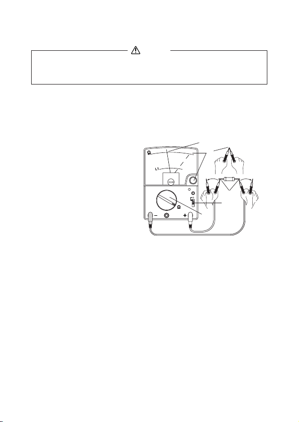
6−8−2 直流電流増幅率(hFE)の測定
1) 測定対象
トランジスタの直流電流増幅率(h
FE)の概略値を測ります。
2) 測定レンジ
FEレンジ
h
3) 測定方法
①テストリードの赤プ
ラグを+入力端子
(EMITTER)に、黒プ
ラグを−入力端子
(NPNトランジスタ測定の場合)
E…エミッタ
B…ベース
C…コレクタ
⑧
⑤
(COLLECTOR)に差
し込みます。
②中央の測定端子
(BASE)にわにくちク
リップ付きリード線
(CL-506)を差し込み
ます。
③ファンクション切り
換えつまみをh
FE位置
①
②
トランジスタ
⑨
④
③
①
に合わせます。
④極性切り換えスイッチはトランジスタの種類により切り換えま
す。NPN型の場合は+側、PNP型の場合は−側です。
⑤赤、黒両テストピンをショートし、0Ω・C∞調整器つまみを回
して、メータの指針をΩ目盛の0目盛線に合わせます。
⑥トランジスタのベース(B)端子に、わにくちクリップ付きリ
ード線のクリップを接続します。
⑦トランジスタのエミッタ(E)に赤プラグを、コレクタ(C)に
黒プラグをそれぞれ接触させます。
⑧メータの指示をh
FE目盛で読み取ります。
⑨測定後は、トランジスタからクリップおよび赤、黒両テストピ
ンをはずします。
⑨
⑥
⑦
●測定時のベース電流は最大で60μA、測定値が大きくなるほど
小さくなります。h
FE値が500のとき、約10μAです。
− 17−
Page 24

6−9
高圧プローブ(HV-60)による直流高電圧(HV)の測定(別売品)
最大測定電圧 DC30kV
警 告
1. HV-60は微小電流回路の直流高電圧測定用プローブです。
送電線などの強電回路の測定には使用しないこと。
2. 最大測定電圧(DC30kV)を超える電圧を測定しないこと。
3. 測定中はプローブのつばよりピン先側を持たないこと。
4. 測定中はファンクション切り換えつまみを切り換えないこと。
1) 測定対象
テレビのブラウン管アノード電圧など、高インピーダンス回路
(微小電流回路)の直流高電圧を測ります。
2) 測定レンジ
HVPROBE (DC120mV)レンジ
3) 測定方法
①極性切り換えスイッ
⑤
ブラウン管
④
チを+側にセットし
ます。
②高圧プローブの赤プラ
グを+入力端子に、
黒プラグを−入力端
子に差し込みます。
③ファンクション切り
②
②
⑥
④
アースライン
①
③
換えつまみを回して
HVPROBE 120mVレンジに合わせます。
④まず、高圧プローブの黒クリップを被測定回路の−電位側(ア
ースライン)へ確実に接続します。次に+電位側(ブラウン管
の場合はアノード)へ高圧プローブの赤のテストピンを接続さ
せます。
⑤V・A目盛0〜30数字列にてメータの指示をkV単位で読み取ります。
⑥測定後は、被測定回路から高圧プローブのテストピン、クリッ
プの順にはずします。
アノード
⑥
6−10 測定の終了
測定終了後は入力端子からテストリードをはずし、ファンクション
切り換えつまみをOFFにします。
− 18−
Page 25

【7】保守管理について
警 告
1. この項目は安全上重要です。
本説明書をよく理解したうえで管理を行ってください。
2. 安全と確度の維持のために 1年に 1回以上は校正、点検を行って
ください。
7−1 保守点検
1)外観
●落下などにより外観(パネル、リヤケースなど)が破損し
ていないか?
2)テストリードと内蔵ヒューズ
●入力端子にプラグを差し込んだときに緩みはないか?
●テストリードのどこかに芯線など、金属部分の露出してい
る箇所はないか?
●テストリードおよびヒューズが切れていないかどうかは、7ペ
ージの点検用フローチャートにて確認してください。
以上の点検で破損や、断線を見つけた場合は、そのままの状態で
使用せずに、製造元へ修理依頼するか新品と交換してください。
7−2 校正点検
校正、点検は製造元でも行っています(有料)。
詳細は三和電気計器
の項を参照)へお問い合わせください。
7−3 内蔵電池・ヒューズの交換
1. 入力端子に電圧が加わった状態でリヤケースをはずすと、感
電のおそれがあります。必ず、電圧の加わっていないことを
確認してから作業を行うこと。
2. 作業時にヒューズ、電池以外の内部の部品に手を触れないこと。
3. 交換用ヒューズは仕様と同定格のものを使用すること。別仕様の
ヒューズを使用したり、ヒューズホルダを導線で短絡したりする
ことは絶対にしないこと。
(株)・
羽村工場サービス課(22ページ[送り先]
警 告
− 19−
Page 26

内蔵電池の交換方法
①リヤケース取り付けネジを緩めてリヤケースをパネルからは
ずし、更に、消耗した1.5V電池(R6型)2本または9V電池
(6F22型)1本をはずします。
②新品の電池を電池ホルダへ+、−の極性を間違わないように、
確実にはめ込みます(1.5V電池は新旧電池を混用しないこと)。
★
電池ホルダーへ電池を逆極性に入れるとヒューズがしゃ断します。
③パネルとリヤケースをしっかりとはめ合わせネジ止めします。
内蔵ヒューズの交換方法
ΩやDCAファンクショ
ンに誤って電圧(100V
の電灯線電圧など)を
積層電池(9V)
予備ヒューズ
単3型電池
(1.5V)
加えますと、安全のた
め内蔵ヒューズがしゃ
断します。ヒューズが
しゃ断すると本器は全
6F22
R6
R6
く動作しなくなります。
①リヤケース取り付け
ネジを緩めてリヤケー
スをパネルからはず
します。
②回路基板上のヒュー
ズホルダから溶断し
たヒューズを抜き取
り、新品のヒューズ
と交換します(予備
ヒューズをご利用く
ヒューズ
ださい)。
③リヤケースを元通りネジ止めします。
④各ファンクションの指示が正常に動作するかチェックします。
●ヒューズのしゃ断と同時に回路部品が焼損して動作不良とな
ることがあります。
●ヒューズの定格:500mA/250V(φ 5×20mmセラミック管)
速断型、しゃ断容量1500A、商品番号F1176
− 20−
Page 27

7−4 清掃と保管について
注 意
1. パネル、リヤケース、メータカバーは揮発性溶剤(シンナー
やアルコールなど)で変質することがあります。
汚れは柔らかい布で、乾拭きをするか少量の水を含ませて拭
き取ってください。
2. パネル、リヤケース、メータカバーなどは熱に弱いため、はん
だごてなど熱を発生するものの近くに置かないでください。
3. 振動の多い場所、落下のおそれのある場所に保管しないでく
ださい。
4. 直射日光下、高温(炎天下の自動車内など)または低温、多
湿、結露のおそれのある場所での保管は避けてください。
5. 長期未使用の場合は必ず内蔵電池を抜いて保管してください。
以上の注意項目を守り、環境の良い場所(【9】9-1項参照)に保管
してください。
【8】アフターサービス
8−1 保証期間について
本製品の保証期間は、お買い上げの日より 3 年間です。
ただし、日本国内で購入し日本国内でご使用いただく場合に限り、
また、許容差は1年保証、製品付属の電池、ヒューズ、テストリー
ド等は保証対象外とさせていただきます。
8−2 修理について
1)修理依頼の前に次の項目をご確認ください。
●内蔵電池が消耗していませんか? 装着の極性は正しいで
すか?
●内蔵ヒューズはしゃ断していませんか?
●テストリードは断線していませんか?
2)保証期間中の故障修理
●保証書の記載内容によって修理させていただきます。
3)保証期間経過後の修理
●修理によって本来の機能が維持できる場合、ご要望により
有料で修理させていただきます。
●修理費用や輸送費用が製品価格より高くなることがありま
すので、事前にお問い合わせください。
− 21−
Page 28

●本器の補修用性能部品の保有期間は、製造打切り後 6 年間
です。この期間を修理可能期間とさせていただきます。
ただし、購買部品の入手がその製造会社の製造中止などに
より不可能になった場合には、保有期間が短くなる場合も
ありますのでお含みおきください。
4)修理品の送り先
●製品の安全輸送のため、修理品の5倍以上の箱にテストリード
も一緒に入れ、十分なクッションを詰めてお送りください。
●箱の表面には「修理品在中」と明記してください。
●輸送にかかる往復の費用はお客様のご負担とさせていただ
きます。
[送り先] 三和電気計器株式会社・羽村工場サービス課
〒205-8604 東京都羽村市神明台4-7-15
TEL(042)554-0113/FAX(042)555-9046
5)補修用ヒューズについて
補修用ヒューズをお求めの場合は上記サービス課宛に、本器の
機種名とヒューズのサイズ、定格、商品番号、必要数量を明記
して、ヒューズの代金と送料分の切手を同封してご注文くだ
さい。
〈サイズ〉 〈定 格〉 〈単 価〉 〈送 料〉
φ5×20mm 500mA/250V
¥190(税込 ¥200)
¥120
セラミックヒューズ/遮断容量1500A 商品番号 F1176
8−3 お問い合わせ
三和電気計器株式会社
―
東京本社 :TEL(03)3253
大阪営業所 :TEL(06)6631
4871/ FAX(03)3251―7022
―
7361/ FAX(06)6644―3249
ホームページ :http://www.sanwa-meter.co.jp
お客様計測相談室 : 0120―51―3930
受付時間 9:30〜12:00 13:00〜17:00(土日祭日を除く)
(10本まで)
説明書中の仕様や内容については予告なしに変更、中止するこ
とがございますのでご了承ください。
− 22−
Page 29

【9】 仕 様
9−1 一般仕様
AC整流方式 :半波整流
メータ仕様 :内磁型トートバンド、15μA
許容差保証温湿度範囲
使用温湿度範囲 :5〜40℃、湿度は下記の通りで、結露の無いこと
保存温湿度範囲 :−10〜50℃、70%RH以下、結露の無いこと
使用環境 :高度2000m以下、汚染度Ⅱ、屋内使用
電源(内蔵電池) :単3(R6) 2本、積層型 9V(6F22) 1本
*出荷時の電池について
工場出荷時にモニター用電池が組み込まれておりますので、記載された電池寿命に満
たないうちに切れることがあります。
モニター用電池とは製品の機能や性能をチェックするための電池のことです。
内蔵ヒューズ :F
寸法・重量 :165(H)×106(W)×46(D)・約370g
付属品 :取扱説明書 1、テストリード TL-21a1
安全規格 :IEC61010-1(EN61010-1)2nd:2001
EMC指令 :IEC61326:1997+A1:1998+A2:2001
:23±2℃、75%RH以下、結露の無いこと
:5〜31℃で80%RH(最大)、31<〜40℃では
80%RHから50%RHへ直線的に減少
:
(長期保管時には、内蔵電池をはずしておくこと)
500mAH/250V(φ5×20mmセラミック管)速断
型、しゃ断容量1500A、商品番号F1176
:クリップ付きリード CL-506a :1
:予備ヒューズ0.5A/250V :1
(本体に内蔵)
:測定分類Ⅲ(AC・DC600V)汚染度2に準拠
測定分類(CATⅠ): コンセントから電源変圧器(トランス)等
を経由した機器内の二次側電路。
測定分類(CATⅡ): コンセントに接続する電源コード付き機
器の一次側電路。
測定分類(CATⅢ):
直接分電盤から電気を取り込む機器の一次
側および分岐部からコンセントまでの電路。
9−2 別売付属品
●携帯ケース(C-CA)
●高圧プローブ(HV-60)
測定範囲:DC0〜30kV 内部抵抗:1000MΩ
本器(CX506a)との組み合わせ許容差:±20%
− 23−
Page 30

9−3 測定範囲および許容差
許容差保証温湿度範囲:23±2℃、75%RH以下、結露の無いこと
姿勢(本器の置かれている状態):水平に対して±5°以内
ACVレンジは正弦波交流50/60Hzで規定
ファンクション
直流電圧
(DCV )
交流電圧
(ACV〜)
直流電流
(DCA )
抵 抗
(Ω)
静電容量
(μF)
端子間
電 流
(μA/mA)
直流電流
増幅率
(hFE)
測定レンジ(最大目盛値)
120m
3/12/30/120/
300/1000
3/12/30/120/
300/750
30μ/0.3m/3m
30m/0.3
5k(×1)/50k(×10)
/500k(×100)
/5M(×1k)
/50M(×10k)
C1レンジ:50p〜0.2μ
C2レンジ:0.01〜20μ
C3レンジ:1〜2000μ
0〜80μA(Ω×1kレンジ)
0〜800μA(Ω×100レンジ)
LI
0〜8mA(Ω×10レンジ)
0〜80mA(Ω×1レンジ)
0〜1000
許容差 備 考
最大目盛値の±4%以内
最大目盛値の
±2.5%以内
最大目盛値の
±3%以内
(12V以下±4%以内)
最大目盛値の
±2.5%以内
(30μA、0.3Aレン
ジは±3%以内)
目盛長さの
±3%以内
目盛長さの
±6%以内
概略値
概略値
概略値
内部抵抗 4kΩ
内部抵抗 50kΩ/V
1000Vレンジ 15kΩ/V
内部抵抗 8kΩ/V
ヒューズを除く
電圧降下:120mV
(0.3Aレンジのみ300mV)
中央目盛値 38Ω(×1レンジ)
最大目盛値 5kΩ(×1レンジ)
開放電圧 3V
(×10kレンジのみ12V)
内蔵発振器で測定
充電電流測定式
抵抗レンジにて抵抗な
どを測定するとき、被
測定物(測定端子間)に
流れる電流
トランジスタの
直流電流増幅率
h
FE=Ic/Ib
●
交流電圧(ACV〜)ファンクションの周波数範囲(影響量±3%以内)
3、12Vレンジ:40Hz〜30kHz 30Vレンジ以上:40Hz〜10kHz
− 24−
Page 31

[1]
SAFETY PRECAUTIONS:
Before use, read the following safety precautions
This instruction manual explains how to use your multitester
CX506a, safely.
Before use, please read this manual thoroughly. After reading it,
keep it together with the product for reference to it when necessary.
The instruction given under the heading
WARNING CAUTION
must be followed to prevent accidental burn or electrical shock.
1-1 Warning Instruction for Safe Use
WARNING
To ensure that the meter is used safely, be sure to observe the
instruction when using the instrument.
Please be careful that the protection circuit may be undermined by
unjustifiable usage that does not follow the guidelines in the
instruction manual.
11. Never use the meter on the electric circuits that exceed 6kVA.
12. Pay special attention when measuring the voltage of AC 33
Vrms (46.7V peak) or DC 70V or more to avoid injury.
13. Never apply an input signals exceeding the maximum rating
input value.
14. Never use the meter for measuring the line connected with
equipment (i.e. motors) that generates induced or surge
voltage since it may exceed the maximum allowable voltage.
15. Never use the meter if the meter or test leads are damaged or
broken.
16. Never use uncased meter.
17. Be sure to use a fuse of the specified rating or type. Never use a
substitute of the fuse or never make a short circuit of the fuse.
18. Always keep your fingers behind the finger guards on the
probe when making measurements.
19. Be sure to disconnect the test pins from the circuit when
changing the function or range.
10. Before starting measurement, make sure that the function and
range are properly set in accordance with the measurement.
11. Never use the meter with wet hands or in a damp environment.
12. Never open rear case except when replacing batteries or fuse.
Do not attempt any alteration of original specifications.
13. To ensure safety and maintain accuracy, calibrate and check
the tester at least once a year.
14. Indoor use.
—
—
25
Page 32

1-2 Explanation of Warning Symbols
The meanings of the symbols used in this manual and attached to
the product are as follows.
: Very important instruction for safe use.
・
The warning messages are intended to prevent accidents to
operating personnel such as burn and electrical shock.
・The caution messages are intended to prevent damage to the
instrument.
: DC : Diode
: AC : Ground
: Resistance : Plus
Ω
: Capacitance : Minus
:
DC Current Amplification Factor
h
FE
Fuse & Diode Protection
:
+
−
: Fuse
: Double insulation
1-3 Overload Protections
Functions
DCV
ACV
DCV
ACV
DCV
DCA
Ω
h
FE
1000
750
120/300
3/12/30
120mV
30µ/0.3m
3m
30m/0.3
X1〜X10k
C1/C2/C3
−
Input terminals
+,−
・EMITTER
・COLLECTOR
Maximum overload protection input (within 5s)
DC・AC 1000V or peak max 1400V
DC・AC 750V or peak max 1100V
DC・AC 200V or peak max 280V
DC・AC 1mA
DC・AC 10mA
DC・AC 0.5A
DC・AC 100V
or
peak max 140V
DC・AC 50V or peak max 75V
DC・AC 50V or peak max 75V
・BASE
1-4 Influence of the electromagnetic field
ACV and Capacitance measurement functions may not work
properly in the electromagnetic field over 10kHz.
—
—
26
Page 33

[2] APPLICATION AND FEATURES
Test pins
Plugs
Finger guards
Test probe (red)
Test probe (black)
TL-21a
Removable
test pin covers
When not
covered
・When the removable test pin covers are mounted : CAT.III 600V
・When the removable test pin covers are not mounted: CAT.II 1000V
2-1 Applications
This instrument is portable multimeter designated for
measurement of weak current circuit.
2-2 Features
High-Sensitivity(DC50kΩ /V)meter
Capacitance measurement by built-in transistor oscillator
IEC61010-1 MEASUREMENT CAT- MAX. 600V
Wide measurement functions 26-ch switch
Transistor check function
Polarity reversal switch for DCV and DCA
[3] NAME OF FUNCTIONS
Scale
Pointer
Meter zero position
adjuster
Function/Range
selector
− input terminal
(collector connecting
terminal)
Base connecting
terminal
Panel
Rear case
Ⅲ
0Ω・C∞adjuster
power indicator
function power
switch
(capacitance switch)
Polarity reversal switch
Stand
+ input terminal (emitter connecting
terminal)
Plug
Clip
Clip lead (CL-506a)
—
—
27
Page 34

[4] SCALE READING
Range
Ω X 10k
Ω X 1k
Ω X 100
Ω X 10
Ω X 1
DCV 1000
DCV 120
DCV 12
DCV 120m
ACV 750
ACV 120
ACV 12
Multiplier
X 10k
X 1k
X 100
X 10
X 1
X 10
X 1
X 0.1
X 1
X 10
X 1
X 0.1
Range
DCV 300
DCV 30
DCV 3
ACV 300
ACV 30
DCmA 30µ
DCmA 0.3
DCmA 3
DCmA 30
DCmA 0.3A
Multiplier
X 10
X 1
X 0.1
X 10
X 1
X 1
X 0.01
X 0.1
X 1
X 0.01
*Please read the indication from the right over
the pointer.
Range
C1
C2
FE
h
C3
80mA
8mA
800µA
80µA
ACV 3
How to read the scale value:
Function Range scale No. Conversion Reading
Ω
DCV
ACV
DCmA
X 100
120V
3V
3mA
89 X 100
36 X 100
1.17 X 100...
.9 X 0.1
8900[Ω]=8.9[kΩ]
Multiplier
X 1
X 1
X 1
X 1
X 10
X 1
X 100
X 10
X 1
36 [V]
1.17 [V]
0.9 [mA]
—
—
28
Page 35

[5] DESCRIPTION OF FUNCTIONS
5-1 Selectors, adjusters and switches
Function/Range selector
Turn the instrument on by selecting any measurement range.
Meter zero position adjuster
Turn the adjuster to have the pointer align with the zero line.
(scale left edge)
0Ω・C∞Adjuster
For resistance or hFE measurement, turn the adjuster to have
the pointer align with the zero line (0Ω) while test leads are
shorted.
For capacitance measurement, turn the adjuster to have the
pointer align with ∞ of each C scale while test leads are
shorted, with pressing (locking) the capacitance switch.
Capacitance Switch
Press the switch to measure capacitance at C1 or C2 range. To
lock the switch at ON position, press and turn it to right approx
45 degree.
Power Indicator
The indicator (LED) is blinked when power is on, for capacitance
measurement.
Polarity reversal switch
Shift the switch to minus (−) to reverse polarity for -DCV or DCA measurement.
5-2 How to Use the Stand
Please use the stand that there
is on the side of rear case like a
figure.
How to Use the Stand
—
—
29
Page 36

[6] MEASUREMENT PROCEDURE
6-1 Start-Up Inspection
WARNING
1. Never use meter if the meter or test leads are damaged or
broken.
2. Make sure that the test leads are not cut or otherwise damaged.
6-2
How to select an appropriate range (Selection of a appropriate range)
For voltage or current measurements, select a function/range
selector is higher than the value to be measured. For example,when
measuring 9V, select 12V range. If the value to be measured is
uncertain, select maximum range.
For Ω measurement, select a range that the pointer can be
read by the center of scale.
6-3 Preparation for measurements
Zero position adjustment.
Shift the polarity reversal switch to + position.
Select a proper range and set the switch for measurements.
Zero position
Zero position adjustment
—
—
30
Page 37

Check continuity of
test leads and fuse.
Stop using it and
have it repaired.
Short the red and
black test pins.
Replace the battery
and fuse, and starting
to once more.
Set the switch to
+
position.
START
Main unit
and test leads
damaged ?
Did the
pointer move to
right side ?
Stop using it and
have it repaired.
No problem.
Start measurement.
Damaged
No damaged
YES
NO
Connect the black plug
of the test lead to the
−terminal.
Connect the red plug
of the test lead to the
+terminal.
Set the function range
switch at Ω x 1 range.
—
—
31
Page 38

6-4 Voltage Measurement
WARNING
1.Never apply an input signals exceeding the maximum
rating input value.
2.Be sure to disconnect the test pins from the circuit when
changing the function / range.
3.Select the maximum range and measure, if the value to be
measured is uncertain.
4.Always keep your fingers behind the finger guards on the
probe when making measurements.
6-4-1
DCV Measurement ( ) Max. measurement value 1000VDC
1) Application
Measuring batteries or DC circuits.
2) Measuring range: 120m/3/12/30/120/300/1000 (7ranges)
3) Measurement procedure
Shift the polarity reversal switch to + position.
Connect the black plug of the test lead to the − input
terminal and the red plug to the + input terminal.
Set the function/range selector to an appropriate DCV
range.
Apply the black test pin to the negative potential side of the
circuit to measure and the red test pin to the positive
potential side.
Read the pointer on V・A scale.
After measurement, remove the red and black test pins from
the circuit measured.
When the pointer moves to the−side, shift the polarity
reversal switch to the−position.
—
32
Battery
—
Page 39

6-4-2
ACV Measurement ( ): Max.measurement value 750VAC
1) Application
Measures sine-wave AC voltages such as lighting voltages.
2) Measuring range: 3/12/30/120/300/750 (6ranges)
Outlet
3) Measurement procedure
Shift the polarity reversal switch to + side.
Connect the black plug of the test lead to the − input
terminal and the red plug to the + input terminal.
Set the function/range selector to an appropriate ACV
range.
Apply the black and red test pin to measuring circuit.
Read the pointer on V・A scale.
The AC3V range only uses theAC3Vscale.
After measurement, remove the red and black test pins
from the circuit measured.
When measuring non-sine wave ACV, measuring values
may have errors according to the contortion of the wave.
Band width.
40Hz-30kHz at 3,12V range
40Hz-10kHz at 30V or above ranges
Values measured at 750V shall be read by decupling (X10)
the scale of 0-120. But for the safety, do not measure any
circuits that exceed 6kVA.
—
33
—
Page 40

6-5 DCA Measurement
( ): Max. measuremet value 0.3ADC
WARNING
1. Never apply voltage to
the input terminals.
2. Be sure to make a series
connection via load.
3. Do not apply an input
exceeding the maximum
rated current to the input
terminals.
1) Application
Current in batteries or DC circuit is measured.
2) Measuring range: 30µ/0.3m/3m/30m/0.3A (5ranges)
3) Measurement procedure
Shift the polarity reversal switch to + position.
Connect the black plug of the test lead to the − input
terminal and the red plug to the + input terminal.
Set the function/range selector to an appropriate DCA
range.
Apply the black test pin to the negative potential side of the
circuit to measure and the red test pin to the positive
potential side.
Read the pointer on V・A scale.
After measurement, remove the red and black test pins from
the circuit measured.
○
Correct
Power
Load
×
Incorrect
Power
Load
Resistor
Battery
At current measurement, according to the size of internal
resistance of the current range, measuring value will be
smaller than actual current.
—
—
34
Page 41

6-6 Resistance Measurement Max. measurement value 50MΩ
WARNING
Never apply voltage to the input terminals.
6-6-1 Resistance Measurement ( Ω )
1) Application
Resistance of resistors or circuits are measured.
2) Measuring range: X1/X10/X100/X1k/X10k (5ranges)
3) Measurement procedure
Shift the polarity reversal switch to + side.
Connect the black plug of the test lead to the − input
terminal and the red plug to the + input terminal.
Set the function/range selector to an appropriate Ω range.
Short the test pins, and adjust 0 Ω・C ∞ by turning adjuster
to have the pointer align with 0 line.
Apply the black and red test pin to the measured resistance.
Read the pointer on Ω scale.
After measurement, remove the red and black test pins from
the resistor measured.
At Ω range, the
polarity of +/− is
reverse from that
marked on the body
panel.
Be sure to use the
rated fuse for the
instrument. In case
a fuse other than
the rated one is
used, indication
errors may occur,
and/or circuit protection is become unable.
Operating voltage for Ω range of this multitester is 3V, so
lighting test of LED can be performed. Appropriate range is
Ω x 10 range.
If the pointer does not move to 0 line even when the 0 Ω
adjuster is turned fully, replace the internal batteries to new
ones.
Resistor
—
—
35
Page 42

6-6-2 Terminal to Terminal Current (LI)
Terminal-to-Terminal Current is the current that runs between
− and + terminals when measuring resistance. There may be
some cases that the impedance of measured object varies,
especially when measuring semi-conductors, due to selfheating caused by current running while measuring resistance.
The maximum LI values are printed on the body panel, at right
side of each range. Readings at each range shall be converted
by multiplying the values (shown below).
µA) Range : LI scale x10, and read as µA.
x1k (80
x100 (800
x10 (8
x1 (80
µA) Range : LI scale x100, and read as µA.
mA) Range : Simply read as mA.
mA) Range : LI scale x10, and read as mA.
—
—
36
Page 43

6-7 Capacitance Measurement ( )
WARNING
1.Never apply voltage to the input terminals.
2.Discharge the capacitance before measuring it.
6-7-1
C1,C2 ranges
1) Application
Measurement of capacitance
2) Measuring range
C1 range : 50pF〜0.2µF
C2 range : 0.01〜20µF
3) Measurement procedure
Shift the polarity reversal switch to + position.
Connect the black plug of the test lead to the − input
terminal and the red plug to the + input terminal.
Set the function/range selector to an appropriate C1 or C2
range.
Push the function power switch. (See 5-1)
Then, the power indicator blinks.
Short the test pins and turn the 0 Ω・C ∞ adjuster to have
the pointer align exactly with ∞ of C1or C2 scale.
Apply the black and red test pin to the measured capacitor.
Read the pointer on C1or C2 scale.
After measurement, remove the red and black test pins from
Capacitor
the object measured.
Turn off the function power switch. (See 5-1)
—
—
37
Page 44

Note
Measuring frequency
C1range : approx. 900Hz C2range : approx. 800Hz
Measuring voltage
C1range : approx.8.0V (peak)/When 200pF is measured
C1range : approx.0.5V (peak)/When 0.05µF is measured
C2range : approx.4.0V (peak)/When 0.1µF is measured
C2range : approx.0.7V (peak)/When 5.0µF is measured
Application
・Test of the cord (Use the C1 range)
Cx 1
Wire breaking point
Cx 2
Cx 1>Cx 2
Continuity or open-wire check of parallel cords, as shown in Fig,
can be done by measuring capacitance between the core wires
(conductors) as a comparison test.
Longer cords are easier to check the detection of the open-wire
because the capacity value lost by leakage between the wires is
proportioned to the length of the wires.
—
—
38
Page 45

6-7-2 C3 range
C3
C3
1) Application
Measured large capacitor
2) Measuring range: C3 range: 1〜2000µF
3) Measurement procedure
Shift the polarity reversal switch to + side.
Connect the black plug of the test lead to the − input
terminal and the red plug to the + input terminal.
Set the function/range selector to C3 range.
Discharge the capacitance before measuring it.
Short the test pins and turn the 0 Ω・C ∞ adjuster to have
the pointer align exactly with ∞ of C3 scale.
Apply the test pins to the measuring capacitor. Then, read
the maximum reading on the C3 scale.
The pointer moves to right direction scale by the charge
current to the capacitor. However, the pointer starts gradual
returning from a certain point. Read the indicated maximum
value on C3 scale.
After measurement, remove the red and black test pins
from the object measured.
Capacitor
Wire
Pay attention to the polarity (+/ −) of the capacitor.
(Connect +side of the capacitor to black test pin.)
It is not possible to measure the electric double layer
capacitor.
—
—
39
Page 46

6-8 Transistor Measurement
WARNING
Never apply voltage to the input terminals.
6-8-1 ICEO Measurement
1) Application
Measuring Iceo of transistor
2) Measuring range: h
3) Measurement procedure
Connect the black plug of the test lead to the − input
terminal and the red plug to the + input terminal.
Set the function/range selector to hFE function.
Set the polarity reversal switch to either NPN or PNP
position according to the transistor (hereinafter simply called
TR.) to be measured. (NPN-TR: NPN position PNP-TR:
PNP position)
Short the test pins and turn the 0 Ω・C ∞ adjuster to have
the pointer align exactly with 0 line of Ω scale.
Connect the emitter of TR and the collector of TR to each
measuring terminal (pin of test lead).
Read the pointer on LI scale. (X10mA)
After measurement, remove the red and black test pins from
the TR.
Good or Bad shall be determined by comparison to
standard TR.
Except large power TR, reading of the I
TR is almost 0mA.
Case of NPN-TR
FE range
CEO of normal silicon
transistor
—
—
40
E: emitter
B: base
C: collector
Page 47

6-8-2 hFE Measurement
1) Application
Measuring h
2) Measuring range: h
FE of transistor
FE range
3) Measurement procedure
Connect the black plug of the test lead to the COLLECTOR
(−input) terminal and the red plug to the EMITTER (+
input) terminal.
Connect the black plug of the clip lead to the BASE terminal.
Set the function/range selector to hFE function.
Set the polarity reversal switch to either NPN or PNP
position according to the transistor (hereinafter simply called
TR.) to be measured. (NPN-TR: NPN position PNP-
TR:PNP position)
Short the test pins and turn the 0 Ω・C ∞ adjuster to have
the pointer align exactly with 0 line of Ω scale.
Connect the base of TR to the base terminal (clip lead).
Connect the emitter of TR and the collector of TR to each
measuring terminal (pin of test lead).
Read the pointer on hFE scale.
After measurement, remove the test pins and the clip lead
from the TR.
Case of NPN-TR
transistor
—
—
41
E: emitter
B: base
C: collector
Page 48

6-9 DC High Voltage measurement (HV) (Optional HV Probe)
Max. measurement value 30kV DC
WARNING
1.The probe is designed for the measurement of very small
direct current circuit. Never use the probe to measure
high voltage in power lines, such as transmission and
distribution lines; it is very dangerous.
2. Never apply input signals that exceed 30kV.
3. Be sure to disconnect the test pins from the circuit when
changing the function.
4. Always keep your fingers behind the finger guards on the
probe when making measurements.
1) Application
The probe is suitable for measuring voltage of high impedance
circuits, such as CRT anode voltage of TV sets.
2) Measuring range:
HV PROBE (DC120mV)
3)
Measurement procedure
Shift the polarity
reversal switch to +
position.
Connect the black plug
of the HV Probe to t he
−input terminal and
the red plug to the +
input terminal.
Set the function/range
selector to HV PROBE position.
First, connect the clip (black) of the probe to the earth line (−) in
the circuit to be measured, and then apply the measuring pin on
the probe body to your measuring point.
Read the pointer on V・A (0〜30) scale as kV.
After measurement, remove the measuring pin from the
measured circuit, and then remove the clip.
CRT
Earth line
Anode
6-10 End of Measurement
When measurement is end, be sure to return the function/range
selector to the OFF position.
—
—
42
Page 49

[7] MAINTENANCE
WARNING
1.This section is very important for safety. Read and understand
the following instruction fully and maintain your instrument
properly.
2. The instrument must be calibrated and inspected at least once a
year to maintain the safety and accuracy.
7-1 Maintenance and inspection
1) Appearance
Is the appearance not damaged by falling ?
2) Test leads and fuse
Are the test leads not damaged ?
Are the core wire not exposed at any place of the test leads ?
Make sure that the test leads are not cut, referring to the
section 6-1.
If your instrument fails any of above check, do not use it, and have it
repaired or replace it to new one.
7-2 Calibration
The manufacturer may conduct calibration and inspection. For
more information, please contact the dealer or manufacturer.
7-3 How to Replace Battery and Fuse
WARNING
1. If the rear case is removed with input applied to the input
terminals, you may get electrical shock. Before starting the
work, always make sure that no inputs is applied.
2. Be sure to use a fuse that has the same rating so as to
ensure safety and performance of tester.
3. When removing the rear case do not touch the internal parts
or wire with hand.
—
—
43
Page 50

<
How to replace the battery or fuse>
Remove the rear case screw with a screwdriver.
Remove the rear case.
Take out the battery or fuse and replace it with a new one.
Attach the rear case and fix it with the screw.
Check and see whether or not indications of respective ranges
are normal.
Spare fuse
Battery (6F22)
9V X1
Battery (R6)
1.5V X2
9V
Fuse
1.5V
Fuse of the specified rating and type(Parts No. F1176)
500mA/250V
φ5 X 20mm Ceramic tube Fast acting fuse.
Blowout capacity : 1500A
—
—
44
Page 51

7-4 Cleaning and Storage
CAUTION
1. For cleaning, wipe lightly with a soft, and either dry or slightly
water-dampended cloth. Do not use volatile solvent such as
thinner or alcohol for panel, case, and meter cover.
2. The panel and the case are not resistant to heat. Do not place
the instrument near heat-generating devices (such as a
soldering iron).
3. Do not store the instrument in a place where it may be subjected
to vibration or from where it may fall.
4. For storing the instrument, avoid hot, cold or humid places or
places under direct sunlight or where condensation is
anticipated.
Following the above instructions, store the instrument in good
environment. (See 9-1)
[8] AFTER-SALE SERVICE
8-1 Warranty and Provision
Sanwa offers comprehensive warranty services to its end-users and
to its product resellers. Under Sanwa's general warranty policy, each
instrument is warranted to be free from defects in workmanship or
material under normal use for the period of one (1) year from the date
of purchase.
This warranty policy is valid within the country of purchase only, and
applied only to the product purchased from Sanwa authorized agent
or distributor.
Sanwa reserves the right to inspect all warranty claims to determine
the extent to which the warranty policy shall apply. This warranty shall
not apply to fuses, test leads, disposables batteries, or any product or
parts, which have been subject to one of the following causes:
1. A failure due to improper handling or use that deviates from the
instruction manual.
2. A failure due to inadequate repair or modification by people
other than Sanwa service personnel.
3. A failure due to causes not attributable to this product such as
fire, flood and other natural disaster.
—
—
45
Page 52

4. Non-operation due to a discharged battery.
5. A failure or damage due to transportation, relocation or
dropping after the purchase.
8-2 Repair
Customers are asked to provide the following information when
requesting services:
1. Customer name, address, and contact information
2. Description of problem
3. Description of product configuration
4. Model Number
5. Product Serial Number
6. Proof of Date-of-Purchase
7. Where you purchased the product
1) Prior to requesting repair,please check the following:
Capacity of the built-in battery, polarity of installation and
discontinuity of the test leads.
2) Repair during the warranty period:
The failed meter will be repaired in accordance with the conditions
stipulated in 8-1 Warranty and Provision.
3) Repair after the warranty period has expired:
In some cases, repair and transportation cost may become higher
than the price of the product. Please contact Sanwa authorized
agent / service provider in advance.
The minimum retention period of service functional parts is 6 years
after the discontinuation of manufacture. This retention period is the
repair warranty period. Please note, however, if such functional
parts become unavailable for reasons of discontinuation of
manufacture, etc., the retention period may become shorter
accordingly.
4) Precautions when sending the product to be repaired
To ensure the safety of the product during transportation, place the
product in a box that is larger than the product 5 times or more in
volume and fill cushion materials fully and then clearly mark ”Repair
Product Enclosed” on the box surface. The cost of sending and
returning the product shall be borne by the customer.
8-3 SANWA web site
http://www.sanwa-meter.co.jp
E-mail: exp_sales@sanwa-meter.co.jp
—
46
—
Page 53

[9] SPECIFICATIONS
9-1 General Specification
AC Rectifier form
Meter type :Internal magnet, Taut band meter (15µA)
Accuracy assurance Temperature/Humidity range
Operating temperature and humidity
Storage temperature/Humidity range
Built-in battery :R6 (IEC) or UM-3 1.5V
Factory-preinstalled built-in battery
*
A battery for monitoring is preinstalled before shipping, therefore it may
run down sooner than the battery life specified in the instruction manual.
The ”battery for monitoring” is a battery to inspect the functions and
specifications of the product.
Built-in fuse :F500mAH/250V φ5 X 20mm Ceramic tube
Dimension and Weight
Accessories :Instruction manual 1 Spare fuse 1
Safety :IEC 61010-1 (EN61010-1) 2nd : 2001
EMC :IEC 61326 : 1997+A1 : 1998+A2 : 2001
Environmental conditions: Indoor use Altitude up to 2000m
Working circuit voltage: 600 VAC max.
MEASUREMENT CATEGORY
*
・CATⅠ:
・CATⅡ:Primary electrical circuits in equipment connected to
・CATⅢ:Primary electrical circuits of heavy equipment
:Half-wave rectifier form
:23±2℃ 75%RH max. No condensation
:5〜31℃,80%RH max.
<〜40℃,80〜50%RH (decreasing linearly)
31
:−10〜50℃ 70%RH max. No condensation
Fast acting fuse. Blowout capacity : 1500A
:165(H) X 106(W) X 46(D) mm・approx. 370g
Test leads TL-21a 1 Crip lead CL-506a 1
Measurement CATⅢ
Pollution degree 2
Secondary electrical circuits connected to an AC
electrical outlet through a transformer or similar device.
an AC electrical outlet by a power cord.
connected directly to the distribution panel, and
feeders from the distribution panel to outlets.
X2, 6F22 9V X1
*. AC, DC600V max.
—
—
47
Page 54

9-2 Optional Accessories
Clip adapter CL-11 (Red, Black 1set)
・
・HV probe HV-60 (
DC 0〜30kV Internal resistance:1000MΩ
・Carrying case C-CA
9-3 Measurement Range and Accuracy
Accuracy assurance range :23±2℃ 75%RH max.
No condensation
Attitude :Horizontal (±5°)
ACV accuracy in the case of sine wave AC.
Function Full scale value Accuracy Remarks
120m
DCV
3/12/30/120/
( )
300/1000
3/12/30/120/
ACV
( )
300/750
30µ/0.3m/3m
DCA
( )
30m/0.3
5k(X1)/50k(X10)
/500k(X100)
Ω
/5M(X1k)/50M(X10k)
C1range : 50p〜0.2µ
C2range : 0.01〜20µ
( µF )
C3range : 1〜2000µ
0〜80µA (Ω X1k range)
LI
0〜800µA (Ω X100 range)
(µA/mA)
0〜8mA (Ω X10 range)
0〜80mA (Ω X1 range)
hFE
0〜1000
±4% Against full scale
±2.5%
Against full scale
±3%
Against full scale
(up to 12V range
±4% against full scale)
±2.5%
Against full scale
(30µ and 0.3A range
±3% against full scale)
±3% of arc
±6% of arc
Approximate value
Approximate value
Approximate value
Input resistance : 4kΩ
Input resistance : 50kΩ/V
(1000V range : 15kΩ/V)
Input resistance : 8kΩ/V
Voltage drop : 120mV
(0.3A range : 300mV)
Center value 38Ω (X1 range)
Max. value 5kΩ (X1 range)
Release voltage : 3V
(X10k range : 12V)
Use the internal
oscillator
Use the Ω X 1k range
Terminal to terminal
current
h
FE=Ic/Ib
Band width
3V and 12V range : 40Hz〜30kHz 30V range : 40Hz〜10kHz
)
—
—
48
Page 55

Specifications and external appearance of the product described
above may be revised for modification without prior notice.
—
—
49
Page 56

MEMO
Page 57

保証書
ご氏名
ご住所
TEL
保証期間
ご購入日 年 月より 3 年間
型 名
No.
製造
様
この製品は厳密なる品質管理を経てお
届けするものです。
本保証書は所定項目をご記入の上保管
していただき、アフターサービスの際
ご提出ください。
※本保証書は再発行はいたしませんの
で大切に保管してください。
本社=東京都千代田区外神田2−4−4・電波ビル
郵便番号=101-0021・電話=東京(03)3253−4871(代)
CX506a
保証規定
保証期間中に正常な使用状態のもとで、万一故障が発生した場合には無償で修理いたし
ます。ただし下記事項に該当する場合は無償修理の対象から除外いたします。
1. 取扱説明書と異なる不適当な取扱いまたは使用による故障
2. 当社サービスマン以外による不当な修理や改造に起因する故障
3. 火災水害などの天災を始め故障の原因が本計器以外の事由による故障
4. 電池の消耗による不動作
5. お買上げ後の輸送、移動、落下などによる故障および損傷
6. 本保証書は日本国内において有効です。
This warranty is valid only within Japan.
年 月 日 修理内容をご記入ください。
記
※無償の認定は当社において行わせていただきます。
Page 58

Page 59

Page 60

本社=東京都千代田区外神田2−4−4・電波ビル
郵便番号=101-0021・電話=東京(03)3253−4871(代)
大阪営業所=大阪市浪速区恵美須西2−7−2
郵便番号=556-0003・電話=大阪(06)6631−7361(代)
SANWA ELECTRIC INSTRUMENT CO., LTD.
Dempa Bldg, 4-4 Sotokanda2-Chome Chiyoda-ku, Tokyo, Japan
植物油インキを使用しています。
10-1106 2040 2040
 Loading...