

Page 1

726+,%$
Strata® DK
Application Bulletin
December, 1999
ABDK-0005
Remote Expansion Cabinet Applications
This bulletin introd uces two new configurati ons of the Str ata DK424 Remote Expansion Cabinet: the Card
Cage and the Daisy Chain. They are designed to give you more flexibility and economy in satisfying your
customers’ requirements. One application uses a spare DK424 or DK280 Expansion Cabinet as a Card
Cage to hold Remote Expansion Cabinet cards (RRCU). The second application uses one RRCU card at
the base location to support two RRCU cards in separate remote locations in a Daisy Chain configuration.
Basic configuration guidelines have been published in the Strata DK Installation and Maintenance
Manual. Use this bulletin to adjust your configuration. Both applications are hardware-only. There are no
software or programming requ irements for either. Card Cage and Daisy Chain configurati ons can be
combined in a sing l e inst al latio n.
Card Cage Configuration
The original configur ation rules call for all RRCU cards at the base location to be plugge d into the Base
Cabinet. These conservative rules are meant to reduce confusion, minimize proble ms in routing expansion
cables, and assure successf ul installations.
The following describes how to put RRCU cards in a cabinet other than the Base Cabinet. An RRCU card
derives only batter y and ground from the backplane into which it is plugged. As a non-timeslot card, it
neither uses nor interf ere s with the timeslot activity on the backplane. Therefore, it will work successfully
in any slot in any cabinet except the CPU slots of t he Base Cabinet. Available card slots must be within the
reach of the RDCL cable, one end of which must be connected to the data cable connector in the Base
Cabinet. The RDCL cable can reach from the base to the rightmost card slot in a cabinet as far as two
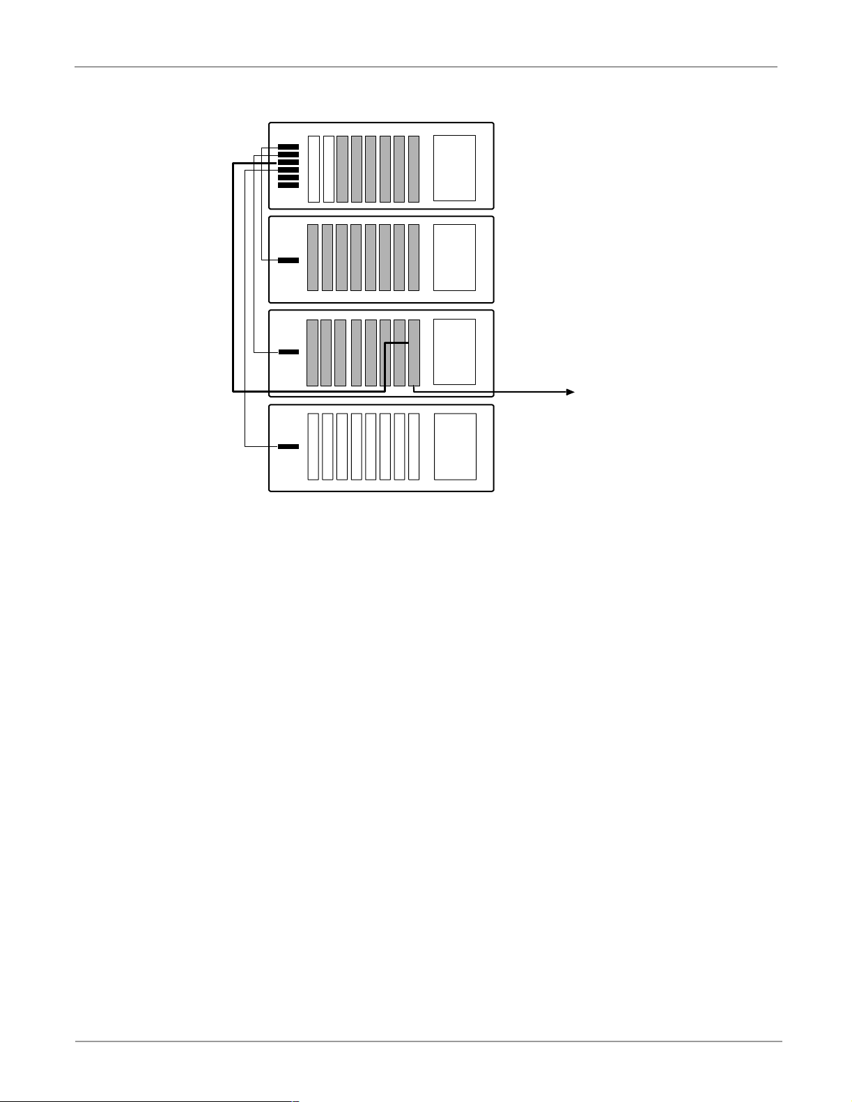
cabinet positions away. Figure 1 shows all the potential card slots for an RRCU shaded in gray.
4170131
Toshiba Americ a Info rm ation S ystems, Inc.
Teleco mm unication Syste m s D i vi si o n
9740 Irvine Blvd., Irvine, C A 92618-1697 (949) 583-3700
http://telecom.toshiba.com
1 of 6
Page 2
Card Cage Configurati on ABDK-0005
2
3
4
5
6
RCTU
RCTU
7
RDCL Cable
PWR
SUPPLY
PWR
SUPPLY
Base Cabinet
Cabinet 2
4798
Figure 1 RRCU Card Placement
As a non-timeslot ca rd with no software or administr at i on e ffect, the RRCU may occupy slot 7 or slot 8 in
the shaded shelves, as shown in Figur e 1. It may also occupy a slo t left vacant for timeslot considerations
such as the slot adjacent to a T-1 or PRI card. An RRCU configured according to these rules still consumes
a card slot in an active Expansion Cabinet and reduces system capacity. The exceptions to this are the
RCTUA, B and C/D systems in which slots 7 and 8 are spare.
It is possible to introduc e an Expansion Cabinet exclusively to hold and power RRCU cards without
reducing system capacity. This Expansion Cabinet and its power supply will funct ion as a “Card Cage.”
The original rules impose a limitation of f ive pairs of RRCUs per system. The Card Cage configuration
permits the installation of up to six pairs of RRCU cards per DK424. This means that all six Expansion
Cabinets can be remotely located without sacrificing slots in the Base Cabinet.
RRCU
PWR
SUPPLY
PWR
SUPPLY
Cabinet 3
Fiber to
Remote
Expansion
Cabinet
Cabinets 4~6
2 of 6
There are two major dif f erences when installing an Expansion Cabinet as a Card Cage. First, it will not be
connected by ribbon cable to the Base Cabinet so the CPU will be unaware of its existence. Second, the
power supply must be jumpered as if the Card Cage were a Base Cabinet. The Card Cage may be
supported by a bat tery backup system in the same ma nner as a conventional Expansion Cabinet but its AC
On/Off switch will ope rate independently of the rest of the cabinet sta ck. See Figure 2.
Remote Expansion Cabinet Applications
Page 3

ABDK-0005 Card Cage Configuration
Base Cabinet
"Card Cage" Cabinet
External Battery
Figure 2 Card Cage Power Connections
The equipment should be well labeled f or the maintenance personnel. What appears as a standard
Expansion Cabinet is a cabinet that is actually isolated from the CPU. It is there exclusively to house and
power RRCU car ds.
AC Input
RPSU
BATT BASE
AC IN
RPSU
BATT
BASE
AC IN
C
n
o
RPSB
RBDB
i
f
l
a
i
t
n
e
d
4799
Figure 3 shows the Card Cage princ iple taken to its extreme. The result is a complete, sev en-cabinet
DK424 made up of one base location and six remot e locati ons with no l oss of system ca pacit y compared to
a conventional instal lation. All the RRCU card s, loc al and rem ote, ar e housed in Car d Cage conf igurat ions.
All card slots in the Expansion Cabinets are available as they would be in a conventional configuration.
d
n
a
Important! An Expansion Cabinet used as a Card Cage supports RRCU cards only. All line, trunk,
I/O, processor and other card s must be in conventional Base Cabinets, Expansion
Cabinets or Remote Expansi on Cabine ts. When powe ring down the system, mak e sure that
the Card Cage cabine t is powered down as well. When powering up, restore the Base
Cabinet or Expansion Cabinet bef ore restoring the Card Cage.
ry
a
n
i
m
i
l
re
P
Remote Expansion Cabinet Applications
3 of 6
Page 4

Daisy Chain Configuration ABDK-0005
RDCL
RDCL
Card Cage
RRCU
Cabinet 4
Card Cage
RRCU
Cabinet 4
Card Cage
RRCU
Base Cabinet
RCTU
RCTU
RDCL Cables
RRCU
RRCU
RRCU
RRCU
RRCU
Card Cage
RRCU
Cabinet 5
RDCL
Card Cage
RRCU
Cabinet 6
RDCL
Card Cage
Card Cage
RRCU
RRCU
Cabinet 4
RDCL
Figure 3 Maximum Card Cage Configuration
Daisy Chain Configuration
An RRCU card can be connected to as many as two highway data cables. That card, connected to its mate
by a pair of multi-mode fiber optic strands, can support two Expansion Cabinets at one remote location.
The Daisy Chain configurati on allows support of one of the Expansion Cabinets in one location and the
second in another location. This configuration can save a card slot at the Base Cabinet a nd, possibly ,
exploit existing fiber cable conditions.
The Daisy Chain configurati on requires one RRCU in the Base Cabinet connected to two highway data
cables and then connected by fiber optics to an RRCU in a Remote Expansion Cabinet. The highway data
signal connects t o M1 at the master loca tion emer ges on connector S1 at the slave and su pports the Remote
Expansion Cabinet for that loc ation . A second RRCU card is install ed at that remote location. See Figure 4.
A new part, the RDCC Remote Daisy Chain Cable is introduced to support this configuration. At the
intermediate sit e, an RDCC cable connects S 2 of the first RRCU card to M1 of the second. The second
RRCU card is connected to its mate at a remote location via multi-mo de fiber as specifie d in the Strata DK
Installation & Maintenanc e Manual. The second RRCU card at the intermediate locati on does not require
an RDCL cable.
Multi-mode Fibers
Cabinet 7
RDCL
4800
4 of 6
Remote Expansion Cabinet Applications
Page 5

ABDK-0005 Daisy Chain Configuration
Fiber Specifications
The total fiber distan ce betwee n points A and D must be within the specifications for a conventional
configuration given in the Installation and Maintenance Manual, typically 3 Kilometers (1.8 miles).
Neither connection (A to B nor C to D) may exceed 2 Kilometers (1.2 miles). See Figure 4.
The specified dB loss budge t of 9 dB applies to e ach fiber conne ction. In other words, ther e may be 9 dB of
loss between points A and B and another 9 dB of loss between points C and D.
l
RDCL
Cables
2
3
4
5
6
7
Figure 4 Daisy Chain Connections
The jumper options on the cards must be installed according to Table 1 which refers to Figure 4 above.
T able 1 RRCU Jumper Options
RRCU
Fiber
<
2 Km
RDCL
Cable
a
Far SiteIntermediate SiteBase Cabinet
a
i
t
n
RRCU
RDCC
RRCU
RDCL
Cable
32
d
M1S1M2S2
e
RRCU
i
f
BACD
C
3 Km
n
o
Fiber
<
2 Km
4801
d
n
RRCU A B C D
Mode Master Slave Master Slave
ry
a
Hardware Required
Additions and changes to the Pric e List are shown in Ta ble 2.
Table 2 Price List Descriptions
n
i
m
RRCU Remote Cabinet Interface Unit
RCTC Remote Cabinet Top Cover As desired for remote Expansion Cabinets.
i
l
re
RDCL
RDCC Daisy Chain Cable
Remote Expansion Cabinet Applications
Remote Cabinet Data Cables (2)
P
and Data Cable Door
One required in the mast er l ocation and one in the slave location for each
remote site. Supports up to two Expansion Cabinets at the remote location.
One RDCL set is required for each RRCU (mas ter and sl ave ) except for the
daisy chain configuration where only one RDCL is required at the
intermediate site.
One required at the inter m ediate site of a daisy chain configuration to
extend the data cable function from one RRCU to the other.
5 of 6
Page 6

Daisy Chain Configuration ABDK-0005
6 of 6
Remote Expansion Cabinet Applications
 Loading...