

Page 1
No. 2D730-148E”O
SERVICE MANUAL
FOR
DIAGNOSTIC ULTRASOUND SYSTEM
MODELS SSA-700A/SSA-770A
(2D730-148E”O)
TOSHIBA MEDICAL SYSTEMS CORPORATION
@I TOSHIBA MEDICAL SYSTEMS CORPORATION 2001-2008
ALL RIGHTS RESERVED
Page 2
No. 2D730-148E*O
IMPORTANT!
1. No part of this manual may be copied or reprinted, in whole or in pat-t,
without written permission.
2. The contents of this manual are subject to change without prior notice
and without our legal obligation.
C-l
*
Page 3
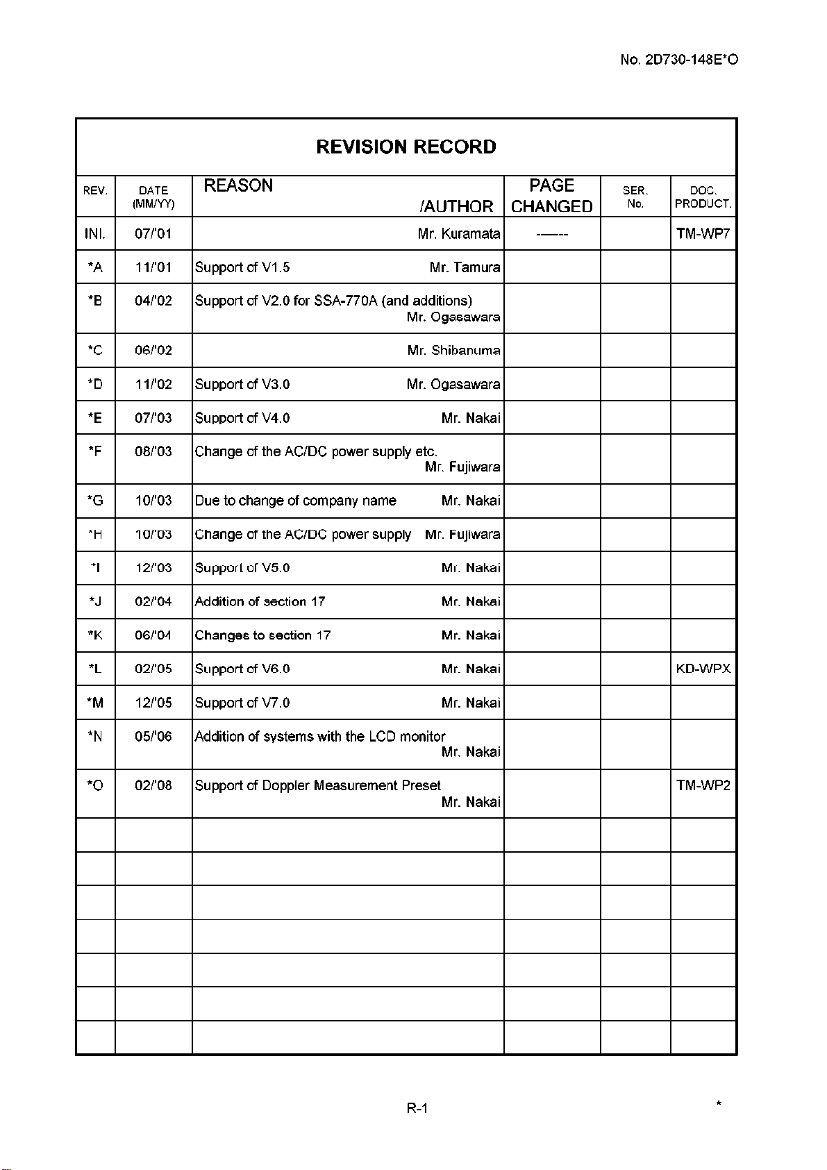
REVISION RECORD
No. 2D730-148E*O
REV. DATE
(MM/W)
REASON PAGE
/AUTHOR CHANGED
INI. 1 07/‘01 1 Mr. Kuramata
*A 1 I/‘01 support of VI .5 Mr. Tamura
*B 04/‘02
I I
*C
*D
*E
*F
06/‘02 Mr. Shibanuma
1 I/‘02 support of v3.0 Mr. Ogasawara
07/‘03 support of v4.0 Mr. Nakai
08/‘03 Change of the AC/DC power supply etc.
Support of V2.0 for SSA-770A (and
additions)
Mr. Ogasawarai 1 1
Mr. Fujiwara
*G 1 IO/‘03 ID ue to change of company name
*H IO/‘03 Change of the AC/DC power supply Mr. Fujiwara
*I 1 12/‘03 Support of V5.0
- ------
SER. DOC.
No. PRODUCT.
I
I I
I I
*J 02/‘04 Addition of section 17 Mr. Nakai
“K 1 06/‘04 Changes to section 17
*L
*M
02/‘05 Support of V6.0 Mr. Nakai KD-WPX
12/‘05 support of v7.0 Mr. Nakai
*N 09’06 Addition of systems with the LCD monitor
Mr. Nakai
02/‘08 Support of Doppler Measurement Preset TM-WP2
Mr. Nakai
I I
R-l
Page 4
Safety Precautions
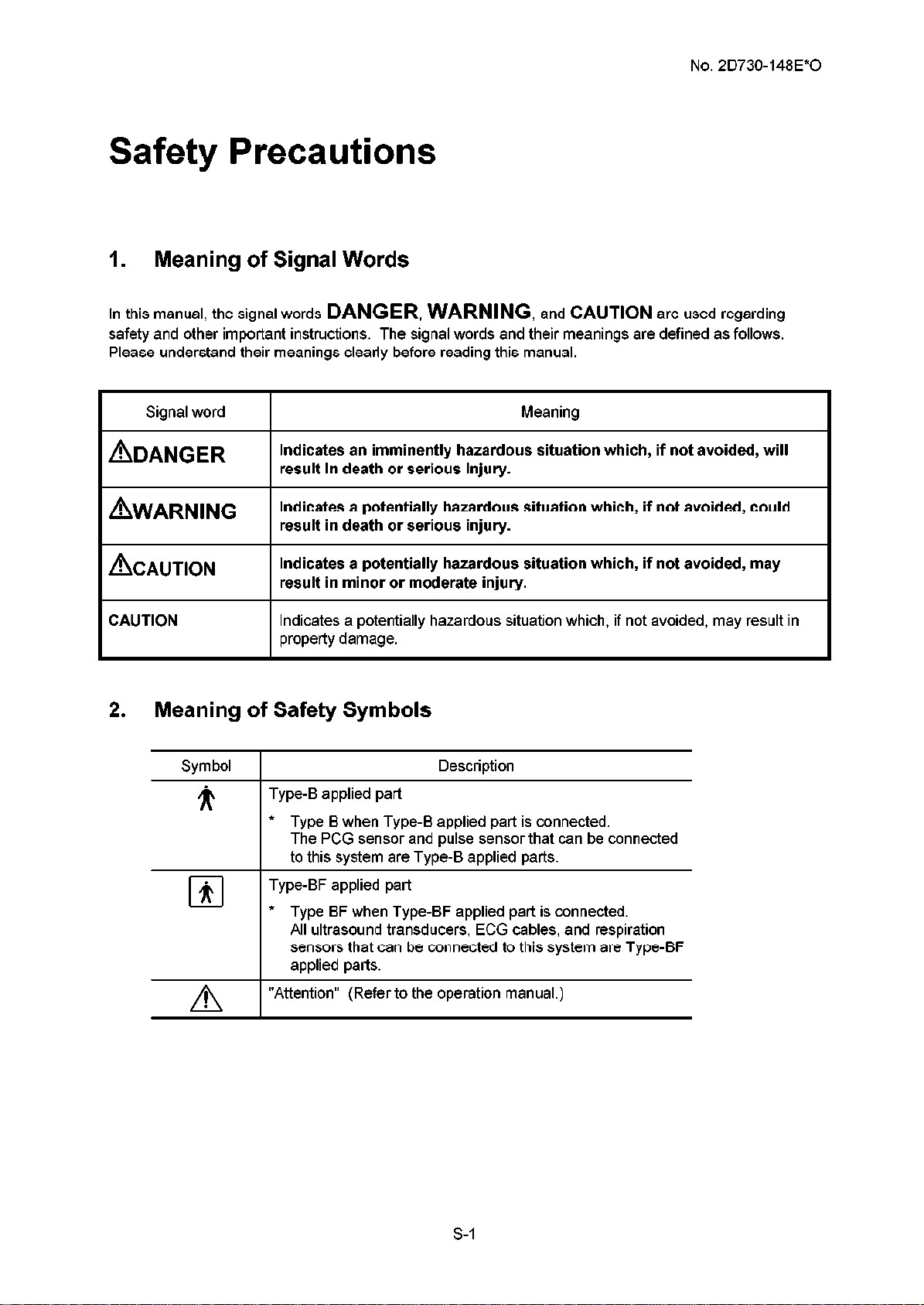
1. Meaning of Signal Words
No. 2D730-148E*O
ln this manual, the signal words
safety and other important instructions. The signal words and their meanings are defined as follows.
Please understand their meanings clearly before reading this manual.
I
I
I
Signal word
ADANGER
AWARNING
ACAUTION
CAUTION
I
Indicates an imminently hazardous situation which, if not avoided, will
result in death or serious injury.
Indicates a potentially hazardous situation which, if not avoided, could
result in death or serious injury.
Indicates a potentially hazardous situation which, if not avoided, may
result in minor or moderate injury.
Indicates a potentially hazardous situation which, if not avoided, may result in
property damage.
DANGER, WARNING,
and
Meaning
CAUTION
are used regarding
2. Meaning of Safety Symbols
Symbol 1
Description
ir I
fi
cl
!
A
Type-B applied part
* Type B when Type-B applied part is connected.
The PCG sensor and pulse sensor that can be connected
to this system are Type-B applied parts.
Type-BF applied part
* Type BF when Type-BF applied part is connected.
All ultrasound transducers, ECG cables, and respiration
sensors that can be connected to this system are Type-BF
applied parts.
“Attention” (Refer to the operation manual.)
S-l
Page 5
No. 2D730-148E*O
3. Safety Precautions
Please observe the following precautions to ensure the safety of service engineers as well as operators
when using this system.
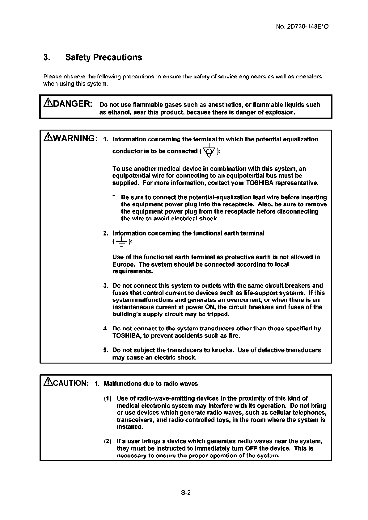
&ANGER: D o no use flammable gases such as anesthetics, or flammable liquids such t
I
, &ARNING: 1. Information concerning the terminal to which the potential equalization
as ethanol, near this product, because there is danger of explosion.
I
conductor is to be connected (
To use another medical device in combination with this system, an
equipotential wire for connecting to an equipotential bus must be
supplied. For more information, contact your TOSHIBA representative.
* Be sure to connect the potential-equalization lead wire before inserting
the equipment power plug into the receptacle. Also, be sure to remove
the equipment power plug from the receptacle before disconnecting
the wire to avoid electrical shock.
2. Information concerning the functional earth terminal
(6):
Use of the functional earth terminal as protective earth is not allowed in
Europe. The system should be connected according to local
requirements.
3. Do not connect this system to outlets with the same circuit breakers and
fuses that control current to devices such as life-support systems. If this
system malfunctions and generates an overcurrent, or when there is an
instantaneous current at power ON, the circuit breakers and fuses of the
building’s supply circuit may be tripped.
4. Do not connect to the system transducers other than those specified by
TOSHIBA, to prevent accidents such as fire.
+
):
ACAUTION:
5. Do not subject the transducers to knocks. Use of defective transducers
may cause an electric shock.
1. Malfunctions due
(1) Use of radio-wave-emitting devices in the proximity of this kind of
medical electronic system may interfere with its operation. Do not bring
or use devices which generate radio waves, such as cellular telephones,
transceivers, and radio controlled toys, in the room where the system is
installed.
(2) If a user brings a device which generates radio waves near the system,
they must be instructed to immediately turn OFF the device. This is
necessary to ensure the proper operation of the system.
to
radio waves
s-2
Page 6
A
- CAUTION:
No. 2D730-148E*O
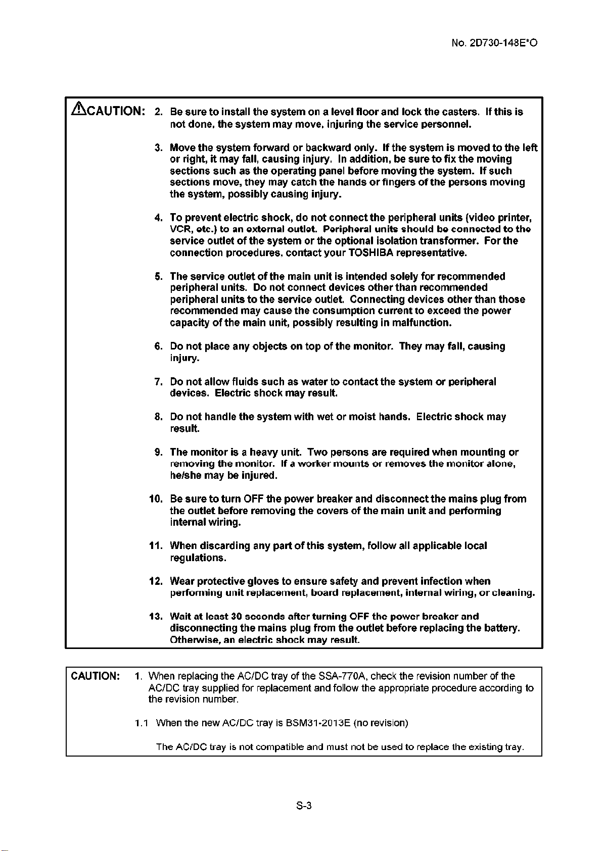
2. Be sure to install the system on a level floor and lock the casters. If this is
not done, the system may move, injuring the service personnel.
3. Move the system forward or backward only. If the system is moved to the left
or right, it may fall, causing injury. In addition, be sure to fix the moving
sections such as the operating panel before moving the system. If such
sections move, they may catch the hands or fingers of the persons moving
the system, possibly causing injury.
4. To prevent electric shock, do not connect the peripheral units (video printer,
VCR, etc.) to an external outlet. Peripheral units should be connected to the
service outlet of the system or the optional isolation transformer. For the
connection procedures, contact your TOSHIBA representative.
5. The service outlet of the main unit is intended solely for recommended
peripheral units. Do not connect devices other than recommended
peripheral units to the service outlet. Connecting devices other than those
recommended may cause the consumption current to exceed the power
capacity of the main unit, possibly resulting in malfunction.
6. Do not place any objects on top of the monitor. They may fall, causing
injury.
7. Do not allow fluids such as water to contact the system or peripheral
devices. Electric shock may result.
8. Do not handle the system with wet or moist hands. Electric shock may
result.
9. The monitor is a heavy unit. Two persons are required when mounting or
removing the monitor. If a worker mounts or removes the monitor alone,
he/she may be injured.
10. Be sure to turn OFF the power breaker and disconnect the mains plug from
the outlet before removing the covers of the main unit and performing
internal wiring.
11. When discarding any part of this system, follow all applicable local
regulations.
12. Wear protective gloves to ensure safety and prevent infection when
performing unit replacement, board replacement, internal wiring, or cleaning.
13. Wait at least 30 seconds after turning OFF the power breaker and
disconnecting the mains plug from the outlet before replacing the battery.
Otherwise, an electric shock may result.
CAUTION: I. When replacing the AC/DC tray of the SSA-770A, check the revision number of the
AC/DC tray supplied for replacement and follow the appropriate procedure according to
the revision number.
1 .I When the new AC/DC tray is BSM31-2013E (no revision)
The AC/DC tray is not compatible and must not be used to replace the existing tray.
s-3
Page 7
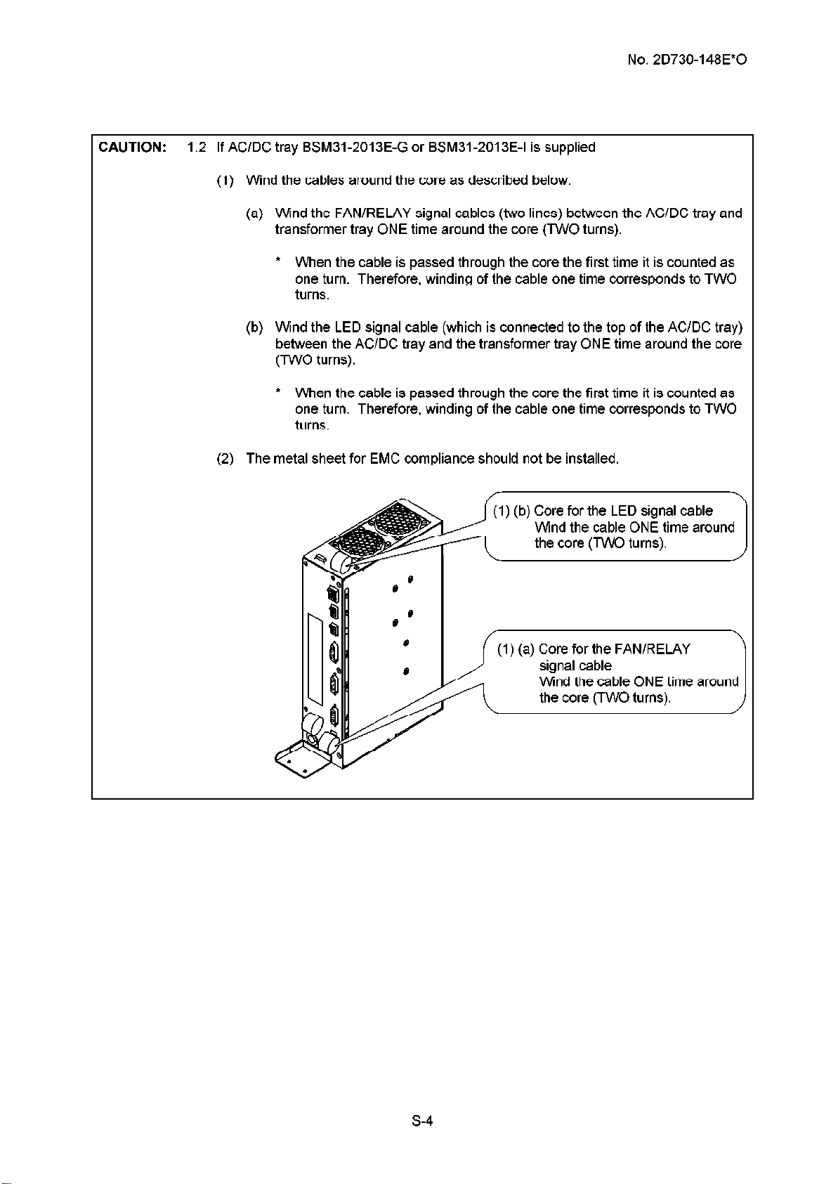
CAUTION: 1.2 If AC/DC tray BSM31-2013E-G or BSM31-2013E-I is supplied
(1) Wind the cables around the core as described below.
(a) Wind the FAN/RELAY signal cables (two lines) between the AC/DC tray and
transformer tray ONE time around the core (TWO turns).
* When the cable is passed through the core the first time it is counted as
one turn. Therefore, winding of the cable one time corresponds to TWO
turns.
(b) Wind the LED signal cable (which is connected to the top of the AC/DC tray)
between the AC/DC tray and the transformer tray ONE time around the core
(TWO turns).
* When the cable is passed through the core the first time it is counted as
one turn. Therefore, winding of the cable one time corresponds to TWO
turns.
(2) The metal sheet for EMC compliance should not be installed.
No. 2D730-148E*O
1) (b) Core for the LED signal cable
(1) (a) Core for the FAN/RELAY
Wind the cable ONE time around
s-4
Page 8
No. 2D730-148E*O
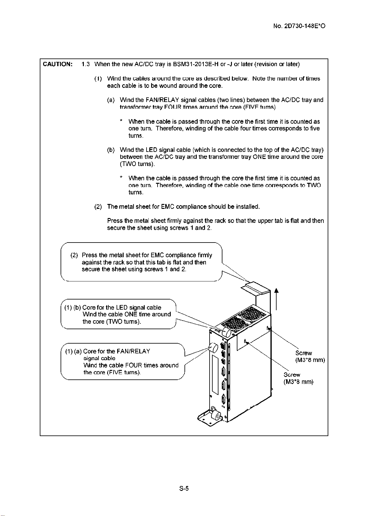
CAUTION: 1.3 When the new AC/DC tray is BSM31-2013E-H or -J or later (revision or later)
(1) Wind the cables around the core as described below. Note the number of times
each cable is to be wound around the core.
(a) Wind the FAN/RELAY signal cables (two lines) between the AC/DC tray and
transformer tray FOUR times around the core (FIVE turns).
* When the cable is passed through the core the first time it is counted as
one turn. Therefore, winding of the cable four times corresponds to five
turns.
(b) Wind the LED signal cable (which is connected to the top of the AC/DC tray)
between the AC/DC tray and the transformer tray ONE time around the core
(TWO turns).
* When the cable is passed through the core the first time it is counted as
one turn. Therefore, winding of the cable one time corresponds to TWO
turns.
(2) The metal sheet for EMC compliance should be installed.
Press the metal sheet firmly against the rack so that the upper tab is flat and then
secure the sheet using screws1 and 2.
(2) Press the metal sheet for EMC compliance firmly
against the rack so that this tab is flat and then
secure the sheet using screws 1 and 2.
/;1) (b) Core for the LED signal cable
Wind the cable ONE time around
the core (TWO turns).
(1) (a) Core for the FAN/RELAY
Wind the cable FOUR times around
the core (FIVE turns).
\I----:.:,
Screw
(M3*8 mm)
\
Screw
(M3*8 mm)
S-5
Page 9
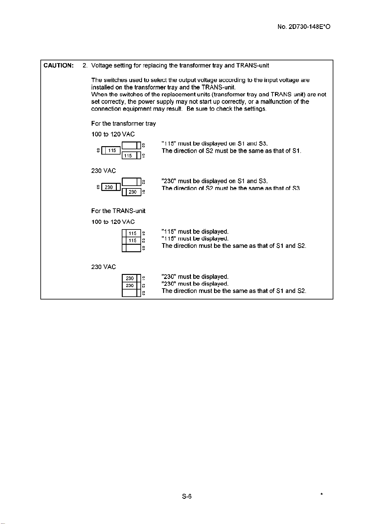
CAUTION: 2. Voltage setting for replacing the transformer tray and TRANS-unit
The switches used to select the output voltage according to the input voltage are
installed on the transformer tray and the TRANS-unit.
When the switches of the replacement units (transformer tray and TRANS-unit) are not
set correctly, the power supply may not start up correctly, or a malfunction of the
connection equipment may result. Be sure to check the settings.
For the transformer tray
100 to 120 VAC
“115” must be displayed on Sl and S3.
The direction of S2 must be the same as that of Sl
230 VAC
“230” must be displayed on Sl and S3.
The direction of S2 must be the same as that of S3
No. 2D730-148E*O
For the TRANS-unit
100 to 120 VAC
230 VAC
“115” must be displayed.
“115” must be displayed.
The direction must be the same as that of Sl and S2
“230” must be displayed.
“230” must be displayed.
The direction must be the same as that of Sl and S2
S-6
*
Page 10
No. 2D730-148E*O
CONTENTS
Page
Safety precautions ________________________________________------------------------------------------------------------------- S-1
INTRODUCTION ________________________________________-------------------------------------------------------------- 1-I
1.
Outline ________________________________________------------------------------------------------------------------- 1-I
1.1
PWB Configuration of Each Unit ________________________________________---------------------------------- I-2
1.2
BLOCK DIAGRAM ________________________________________------------------------------------------------------------ 2-I
2.
DISASSEMBLY AND REMOVAL PROCEDURES ________________________________________--------------------- 3-I
3.
3.1
3.2 Removing the Covers ________________________________________------------------------------------------------ 3-5
3.3 Removing the Handle ________________________________________---------------------------------------------- 3-10
3.4 Removing the Monitor Unit ________________________________________--------------------------------------- 3-12
3.5 Removing the Operating Panel ________________________________________---------------------------------- 3-19
Name of Each Section ------__--------------~~~--------------~~~--------------~~--------------~~~------------ 3-l
3.2.1 For the SSA-77OA-------------------------------------------------------------------------------- 3-5
3.2.2 For the SSA-7OOA-------------------------------------------------------------------------------- 3-7
3.3.1 For the SSA-77OA------------------------------------------------------------------------------ 3-l 0
3.3.2 For the SSf+7OOA ________________________________________-------------------------------------- 3-l 1
3.4.1 Removing the monitor unit (for systems with the CRT monitor)---------------------- 3-12
3.4.2 Removing the monitor unit (for systems with the LCD monitor)---------------------- 3-14
3.4.3
3.4.4 Adjusting the LCD monitor arm vertical movement resistance ----------------------- 3-l 8
Removing the LCD monitor arm ________________________________________--------------------- 3-15
3.5.1 For the SSf+77OA ________________________________________-------------------------------------- 3-l 9
3.5.2 For the SSf+7OOA ________________________________________-------------------------------------- 3-23
3.6 Disassembling the Operating Panel ________________________________________---------------------------- 3-24
3.6.1 Removing the lower cover ________________________________________---------------------------- 3-24
3.6.2 Removing the panel ________________________________________--------------------------- 3-27 upper
3.6.3 Removing the handle -----------___--------------~~~--------------~~--------------~~~---------- 3-28
3.6.4 Removing the trackball section ________________________________________---------------------- 3-29
3.6.5
3.6.6 Removing the keyboard----------------------------------------------------------------------- 3-31
Removing the PWBs (B) and (G) -------------___--------------~~--------------~~~---------- 3-30
-a-
Page 11
CONTENTS - continued
No. 2D730-148E*O
Page
3.7
3.8
3.9
3.10
3.11
3.12
3.13
3.6.7
3.6.8
3.6.9
3.6.10 Removing the near/away slide lever ________________________________________--------------- 3-35
3.6.11
3.6.12 Mounting the switch cover ________________________________________---------------------------- 3-37
Removing the PWB Rack--------------------------------------------------------------------------------- 3-38
Removing the PWBs ________________________________________----------------------------------------------- 3-40
Removing the TI--------------------------------------------------------------------------------------------- 3-41
Removing the 10 -------------__--------------~~~--------------~~~--------------~~--------------~~~---------- 3-42
Removing the HDD Unit ________________________________________------------------------------------------- 3-43
Removing the Battery-------------------------------------------------------------------------------------- 3-44
Removing the AC-DC Unit ________________________________________---------------------------------------- 3-45
Removing the keyboard ________________________________________------------------------------- 3-32
Removing the LCD /.l,SSY ________________________________________---------------------------- 3-33
Removing the PWBs (C), (D), and (E) ________________________________________------------- 3-34
Removing the up/down slide lever ________________________________________------------------ 3-36
3.14
3.15
3.16
3.17
3.18
3.19
3.20
Removing the PSA and PSD ________________________________________------------------------------------- 3-48
Removing the Transformer ________________________________________--------------------------------------- 3-49
Removing the MO ________________________________________-------------------------------------------------- 3-50
Removing the Front panel ________________________________________---------------------------------------- 3-51
3.17.1
3.17.2 For the SSf!,-7OOA ________________________________________-------------------------------------- 3-54
Removing the Rear panel ________________________________________----------------------------------------- 3-55
Removing the PHYSlO Unit ________________________________________-------------------------------------- 3-56
3.19.1
3.19.2 For the SSf+7OOA ________________________________________-------------------------------------- 3-57
Removing the Caster Units ________________________________________--------------------------------------- 3-58
3.20.1
3.20.2 For the SSf!,-7()()p, ________________________________________-------------------------------------- 3-61
For the SSf+77OA ________________________________________-------------------------------------- 3-51
For the SSf+77()A ________________________________________-------------------------------------- 3-56
For the SSA-77OA------------------------------------------------------------------------------ S-58
Cleaning the Air Filters -----__--------------~~~--------------~~~--------------~~--------------~~~---------- 3-62
3.21
Cleaning the panel ----------__--------------~~~--------------~~~--------------~~--------------~~~---------- 3-63
3.22
-b-
Page 12
CONTENTS - continued
No. 2D730-148E*O
Page
3.22.1
Cleaning of key tops ________________________________________----------------------------------- 3-63
3.22.2 Cleaning procedures for parts other than key tops ------------------------------------- 3-63
3.23
Adjusting the Operating Panel Locking Wire ________________________________________----------------- 3-64
3.23.1
3.23.2
3.24
Replacing the Operating Panel Locking Wire ________________________________________----------------- 3-67
3.24.1
3.24.2
3.25
3.26
3.27
Removing the CD-R Unit----------------------------------------------------------------------------------
Cleaning the MO Drive -----__--------------~~~--------------~~~--------------~~--------------~~~----------
Cleaning the palm Switch ________________________________________-----------------------------------------
Adjusting the up/down slide wire ________________________________________-------------------- 3-64
Adjusting the near/away slide wire ________________________________________-----------------
Replacing the up/down slide wire----------------------------------------------------------- 3-67
Replacing the near/away slide wire ________________________________________----------------- 3-72
3.27.1 Cleaning procedures for the old-type palm switch -------------------------------------- 3-83
3.27.2 Cleaning procedures for the new-type palm switch------------------------------------- 3-85
3-66
3-80
3-82
3-83
OpER/T!,TlON OF EACH PWB ________________________________________---------------------------------------------- 4-l
4.
4.1
4.2
Front-End Unit ________________________________________--------------------------------------------------------- 4-l
4.1.1
4.1.2
4.1.3
4.1.4
TI ________________________________________------------------------------------------------------------- 4-5
TR ________________________________________------------------------------------------------------------ 4-g
RCB ________________________________________-------------------------------------------------------- 4-13
CB ________________________________________---------------------------------------------------------- 4-17
BE Unit ________________________________________---------------------------------------------------------------- J-23
4.2.1
BE ________________________________________---------------------------------------------------------- J-24
4.2.2 VI (Video Interface) ________________________________________------------------------------------ 4-35
4.2.3 RM (Realtime
4.2.4
4.3
System-R&t&
4.3.1
1QDA.S
Boar& ----__--------------____________________--------------~~--------------~~~----------
I/O -------------------------------------------------------------------------------------------------- 4-47
Manager)
________________________________________------------------------------ 4-41
(Ip) ________________________________________----------------------------------------------- 4-44
4-47
4.3.2
4.3.3
Front panel --------__--------------~~~--------------~~~--------------~~--------------~~~---------- 4-50
Rear panel --------__--------------~~~--------------~~~--------------~~--------------~~~---------- 4-50
-c-
Page 13
No. 2D730-148E*O
CONTENTS - continued
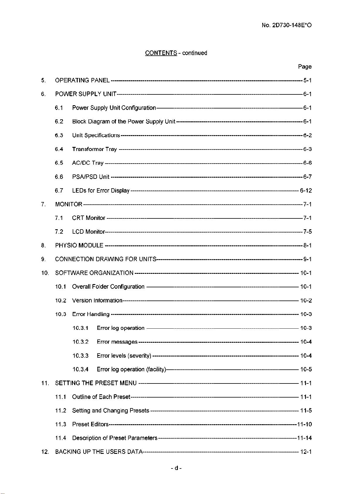
OPERATING PANEL ________________________________________--------------------------------------------------------- 5-I
5.
POWER SUPPLY UNIT ________________________________________------------------------------------------------------ 6-I
6.
Page
6.1
6.2
6.3
6.4
6.5
6.6
6.7
7.
7.1
7.2
8.
CONNECTION DRAWING FOR UNITS ________________________________________---------------------------------- 9-l
9.
10, SOFTWARE ORG/T!,NlZATlON ________________________________________------------------------------------------- 10-l
power Supply Unit Configuration ________________________________________---------------------------------- 6-I
Block Diagram of the power Supply Unit ________________________________________------------------------ 6-I
Unit Specifications ________________________________________---------------------------------------------------- 6-2
Transformer Tray ________________________________________----------------------------------------------------- 6-3
AC/DC Tray --___--------------_____________________------------~~~--------------~~--------------~~~------------ 6-6
pSA/pSD Unit ________________________________________--------------------------------------------------------- 6-7
LEDs for Error Display ------__--------------~~~--------------~~~--------------~~--------------~~~---------- 6-l 2
MONITOR -------------___--------------~~--------------~~~--------------~~~--------------~~--------------~~~------------ 7-l
CRT Monitor ________________________________________----------------------------------------------------------- 7-l
LCD Monitor---------------------------------------------------------------------------------------------------- 7-5
PHySlO MODULE ________________________________________------------------------------------------------------------ 8-I
IO.1 Overall Folder Configuration ________________________________________------------------------------------- 1 O-1
IO.2 Version Information ________________________________________------------------------------------------------- IO-2
IO.3 Error Handling ________________________________________------------------------------------------------------- 1 O-3
10.3.1
10.3.2 Error messages ________________________________________----------------------------------------- 1 O-4
10.3.3 Error levels (severity) ________________________________________---------------------------------- 1 O-4
10.3.4 Error log operation (facility) ________________________________________--------------------------- 1 O-5
11, SETTING THE PRESET MENU ________________________________________----------------------------------------- 11-I
11 ,I Outline of Each preset ________________________________________--------------------------------------------- 11-I
1 I.2 Setting and Changing presets ------------___--------------~~~--------------~~--------------~~~---------- 1 I-5
II.3 preset Editors ________________________________________------------------------------------------------------- 1 I-10
1 I.4 Description of Preset Parameters ----------------------------------------------------------------------l l-l 4
12, BACK1 NG Up THE USERS DATA------------------------------------------------------------------------------- 12-I
Error log operation ________________________________________------------------------------------- 1 O-3
-d-
Page 14
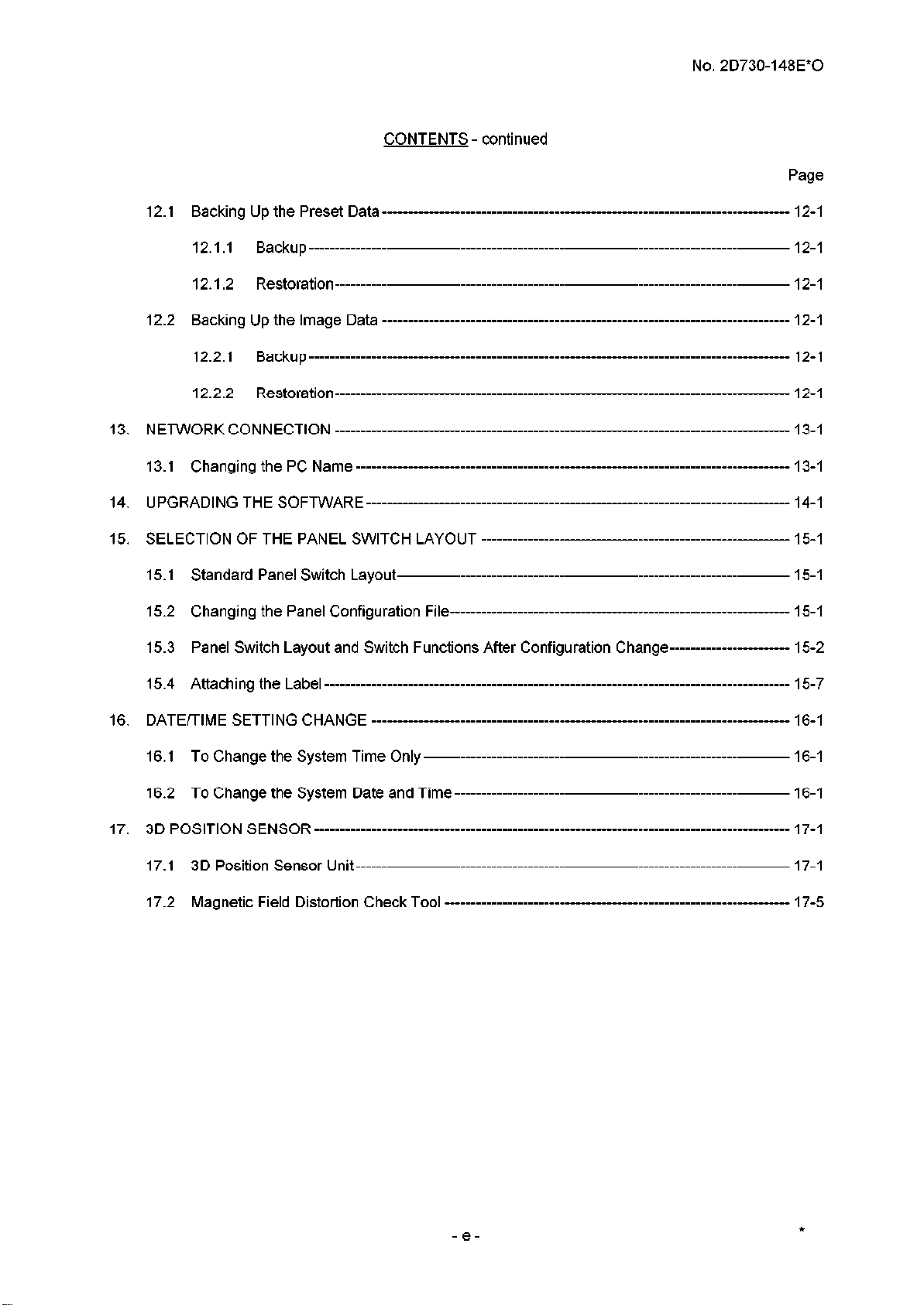
12.1
Backing
No. 2D730-148E*O
CONTENTS - continued
Page
Up the preset Data ________________________________________-------------------------------------- 12-I
12.1.1
12.1 ,‘J
12.2 Backing Up the Image Data ________________________________________-------------------------------------- 12-I
12.2.1
12.2.2 R&oration ________________________________________----------------------------------------------- 12-I
Backup ________________________________________---------------------------------------------------- 12-I
R&oration ________________________________________-----------------------------------------------
Backup ________________________________________---------------------------------------------------- 12-I
12-I
13, N EJWORK CONNECTION --------__--------------~~~--------------~~~--------------~~--------------~~~---------- 13-l
13.1
Changing
the PC Name ________________________________________------------------------------------------- 13-I
14, U PGRADl NG THE SOFTWARE --__--------------______________________------------~~--------------~~~---------- 14-l
15, SELECTION OF THE PANEL SWITCH LAYOUT -------------___--------------~~--------------~~~---------- 15-I
15.1 Standard panel Switch Layout ________________________________________----------------------------------- 15-I
15.2
Changing the panel Configuration File-----------------------------------------------------------------
15-I
15.3 Panel Switch Layout and Switch Functions After Configuration Change----------------------- 15-2
15.4
Attaching
the Label ________________________________________------------------------------------------------- 15-7
16, DATE/TIME SETTING CHANGE ________________________________________---------------------------------------- 16-I
16.1 To
16.2
Change
To Change the System Date and Time ________________________________________------------------------
the
System
Time
Only
________________________________________------------------------------ 16-I
16-I
17, 3D POSITION SENSOR ________________________________________--------------------------------------------------- 17-I
17.1 3D position Sensor Unit ________________________________________------------------------------------------- 17-I
17.2
Magnetic
Field Dist&ion Check TooI ________________________________________-------------------------- 17-5
-e-
*
Page 15

No. 2D730-148E*O
1.
INTRODUCTION
Outline
1.1
The SSA-700A/SSA-770A (hereinafter referred to as Aplio) functions in the 2D, M, FFT Doppler,
and color blood-flow modes. The system is classified into the following five main systems
depending on the combined units.
(1) Front-end unit
(2) Back-end unit
(3) System-related unit
(4) Power supply unit
(5) Monitor
l-l
Page 16
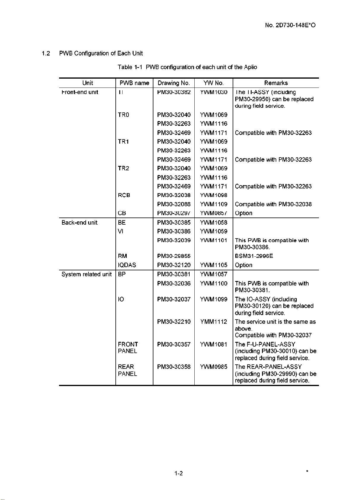
1.2 PWB Configuration of Each Unit
Table l-l PWB configuration of each unit of the Aplio
No. 2D730-148E*O
Unit
Front-end unit
Back-end unit
System related unit
PWB name
TI The TI-ASSY (including
TRO
TRI
TR2
RCB
CB
BE
VI
RM
IQDAS
BP YWM 1057
IO
FRONT
PANEL
REAR
PANEL
Drawing No. YW No.
PM30-30382 YWM 1030
PM30-29950) can be replaced
during field service.
PM30-32040 YWM 1069
PM30-32263 YWM1116
PM30-32469 YWMI 171
PM30-32040 YWM 1069
PM30-32263 YWMIIIG
PM30-32469 YWMI 171
PM30-32040 YWM 1069
PM30-32263 YWM1116
PM30-32469 YWMI 171
PM30-32038 YWM 1098
PM30-32088 YWMI 109
PM30-30297 YWM0857
PM30-30385 YWM 1058
PM30-30386 YWM 1059
PM30-32039 YWMI 101
PM30-29855
PM30-32120 YWMI 105 Option
PM30-30381
PM30-32036
PM30-32037 YWM 1099 The IO-ASSY (including
PM30-32210 YMM1112
PM30-30357 YWM1081
PM30-30358 YWM0985
YWMI 100
Compatible with PM30-32263
Compatible with PM30-32263
Compatible with PM30-32263
Compatible with PM30-32038
Option
This PWB is compatible with
PM30-30386.
BSM31-2996E
This PWB is compatible with
PM30-30381.
PM30-30120) can be replaced
during field service.
The service unit is the same as
above.
Compatible with PM30-32037
The F-U-PANEL-ASSY
(including PM30-30010) can be
replaced during field service.
The REAR-PANEL-ASSY
(including PM30-29990) can be
replaced during field service.
Remarks
l-2
*
Page 17
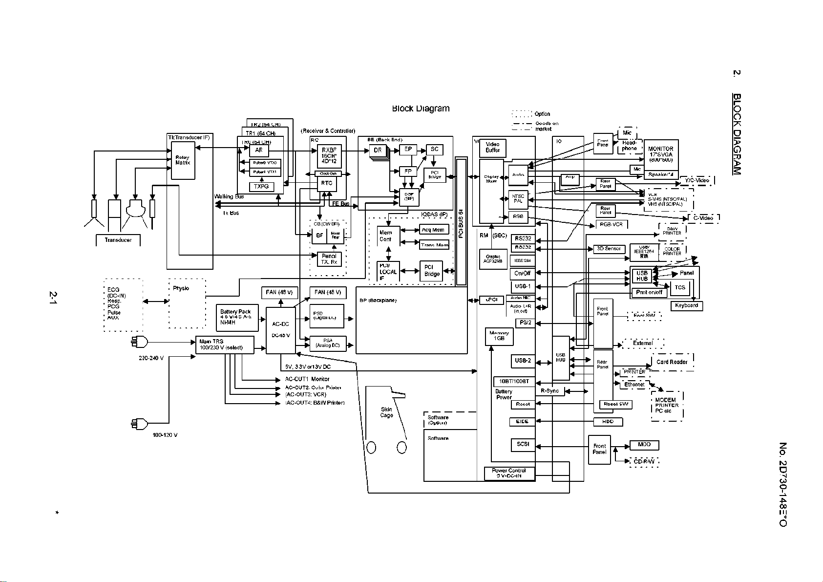
TI(Transducer IF)
Physio
_ . .
RXBF
Block Diagram
BE (Back End)
DRU kl 1
BP (Backplane)
EP SC
- - - Goods on
market
Ma,n TRS
100,230 v (select)
‘I:
DC48 V
5”. 3 3” orl3V DC
, AC-OUT, Monitor
. AC-OUTZ. Color Printer
b (/GOUT3 “CR)
. (AC-OUT4 B&W Printer)
PSA
c
Skin
cage
t
rsoGiia, - 1 (Option)
*
Page 18
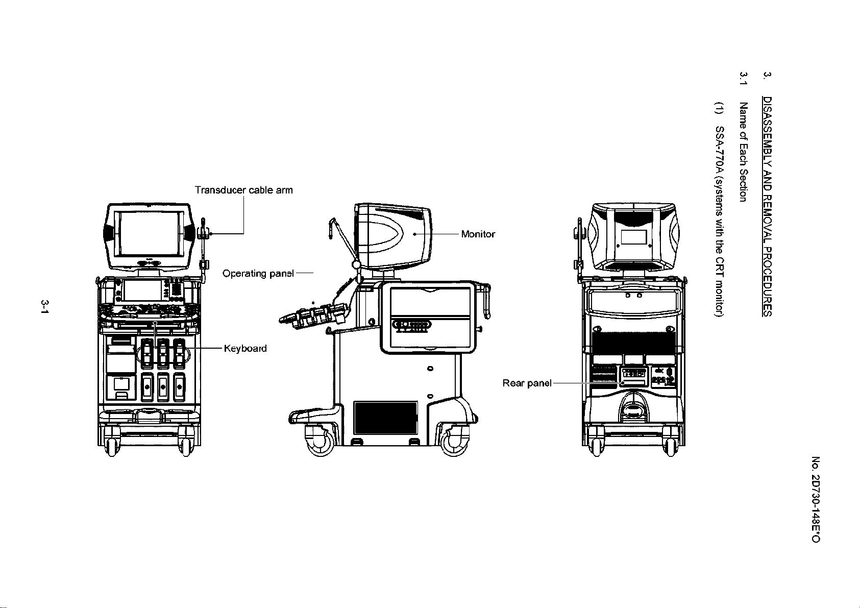
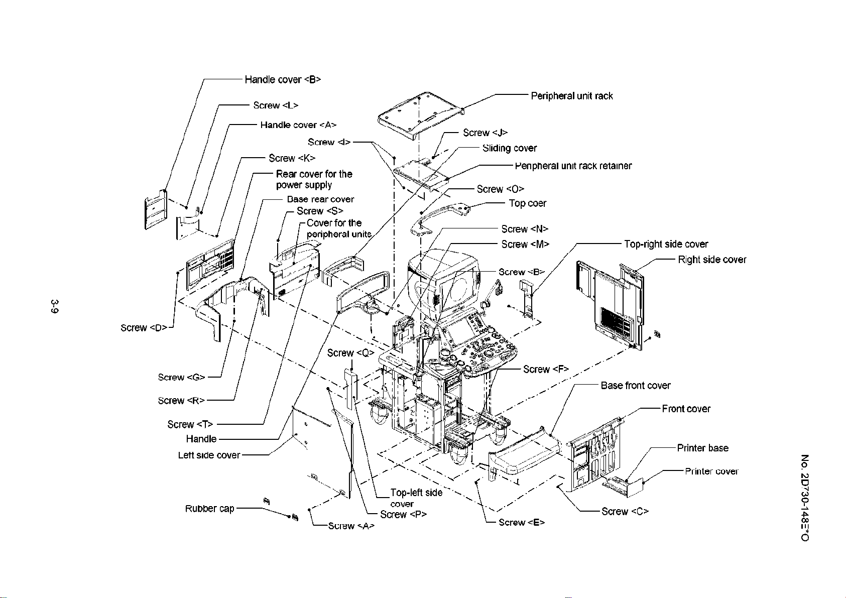
3.1 Name of Each Section
(1) SSA-770A (systems with the CRT monitor)
3. DISASSEMBLY AND REMOVAL PROCEDURES
No. 2D730-148E*O
Page 19
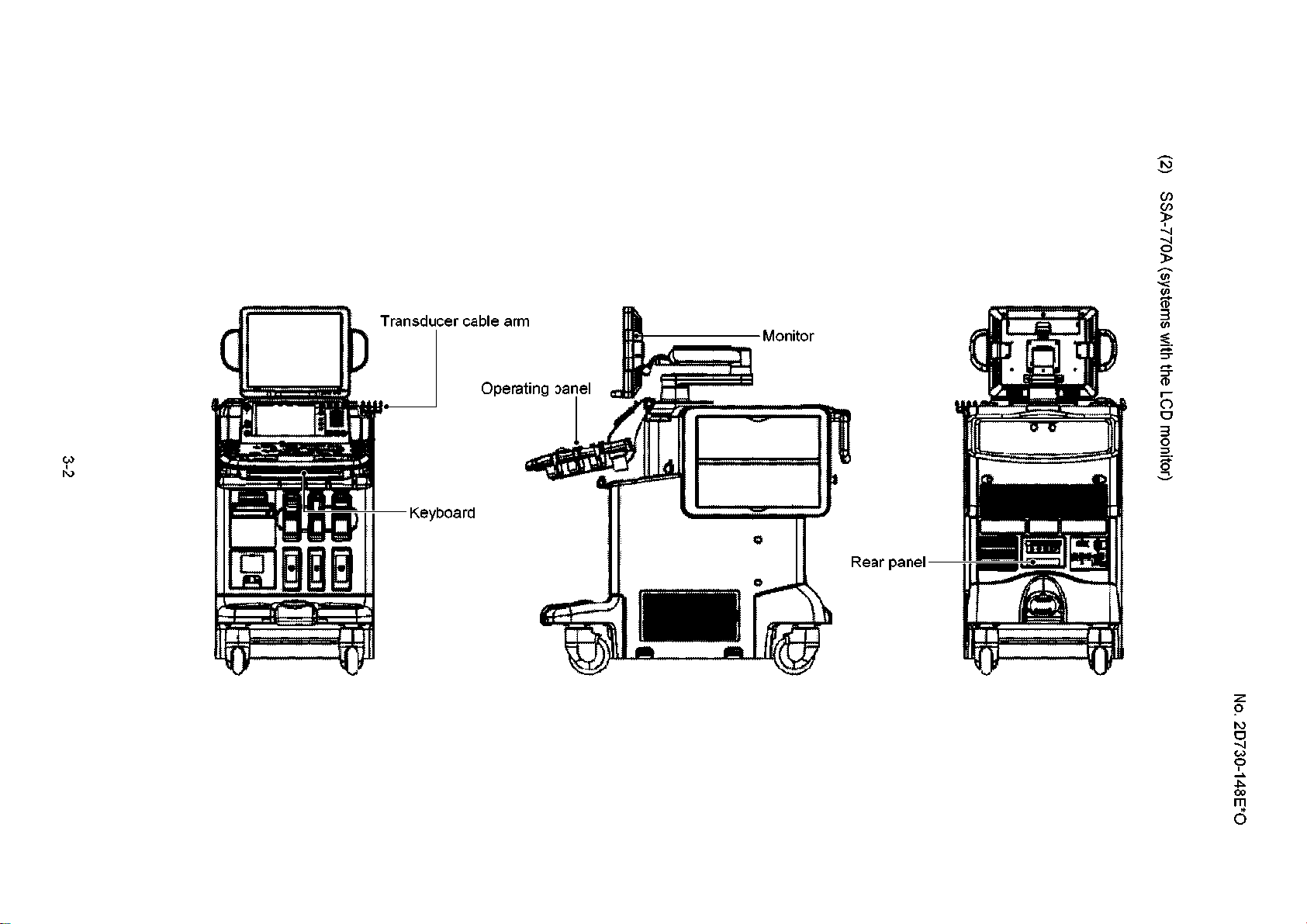
3-2
SSA-770A (systems with the LCD monitor)
No. 2D730-148E*O
Page 20
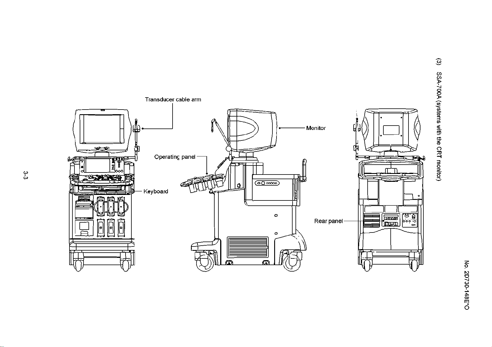
(3) SSA-700A (systems with the CRT monitor)
r
r
No. 2D730-148E*O
Page 21
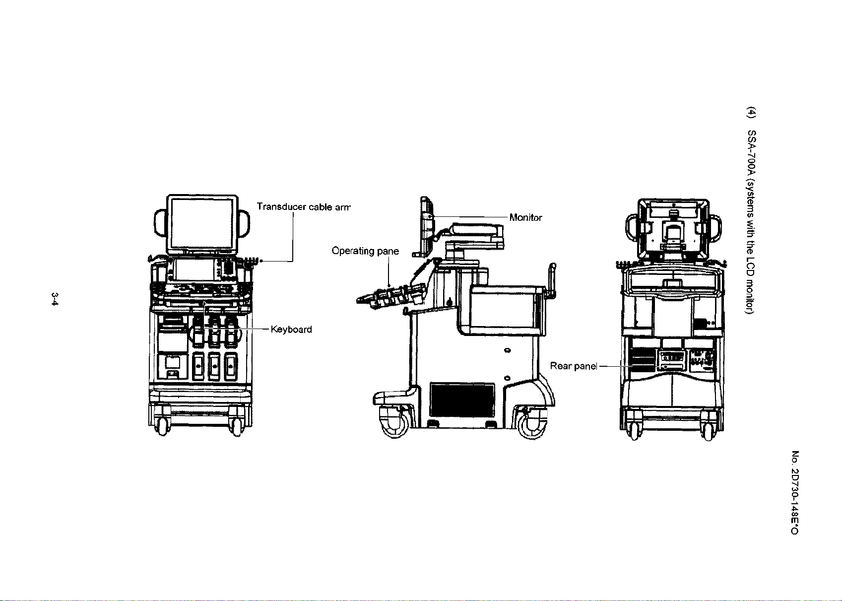
3-4
(4)
SSA-700A (systems with the LCD monitor)
No. 2D730-148E*O
Page 22
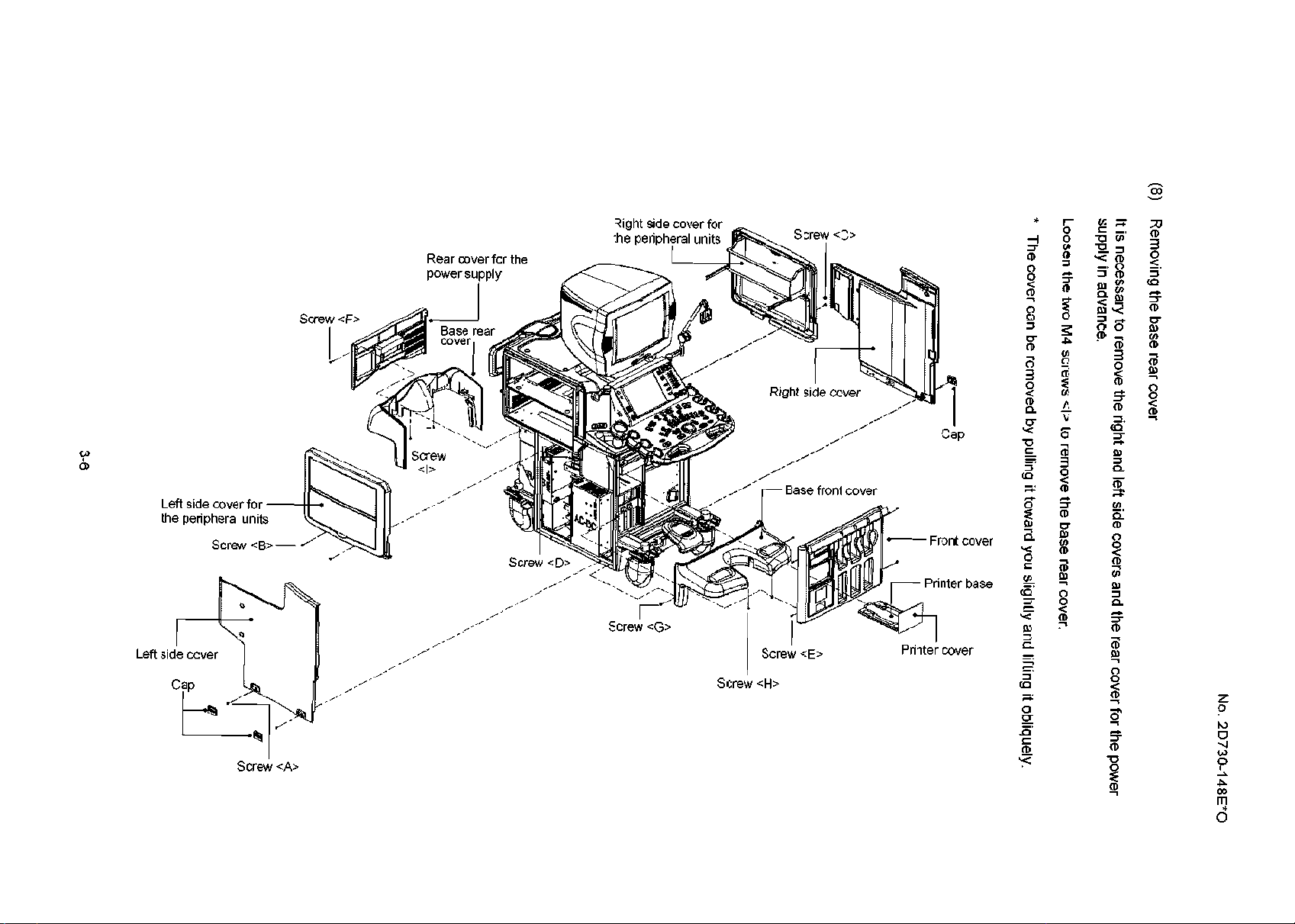
3.2 Removing the Covers
3.2.1 For the SSA-770A
(1) Removing the left side cover
(a) Remove the two rubber caps at the bottom of the cover.
(b) Remove the two M4 screws <A> to remove the left side cover.
* The cover can be removed by pulling the bottom of the cover toward you
Removing the right side cover
(2)
Remove the right side cover in the same manner as the left side cover.
(3) Removing the left side cover for peripheral units
It is necessary to remove the left side cover in advance.
Remove the two M4 screws <B> to remove the left side cover for the peripheral units.
No. 2D730-148E*O
* The cover can be removed by lifting it up and then pulling it toward you.
(4) Removing the right side cover for the peripheral units
It is necessary to remove the right side cover in advance
Remove the two M4 screws CC> to remove the right side cover for the peripheral units.
* The cover can be removed by lifting it up and then pulling it toward you.
Removing the front cover
(5)
When the transducers are connected, remove them.
It is necessary to remove the right and left side covers in advance.
(a) When the blank cover is installed, loosen the M3 screw CD> to remove the blank
cover with the printer base installed.
(b) Remove the four M4 screws <E> to remove the front cover.
(6) Removing the rear cover for the power supply
It is necessary to remove the right and left side covers in advance.
Remove the four M4 screws cF> to remove the rear cover for the power supply.
(7) Removing the base front cover
It is necessary to remove the right and left side covers and the front cover in advance.
(a) Remove the two M4 screws cG>
(b) Loosen the two M4 screws <H> to remove the base front cover
* The cover can be removed by pulling it toward you slightly and lifting it obliquely.
3-5
Page 23
3-6
* The cover can be removed by pulling it toward you slightly and lifting it obliquely.
Loosen the two M4 screws cl> to remove the base rear cover.
supply in advance.
It is necessary to remove the right and left side covers and the rear cover for the power
Removing the base rear cover
No. 2D730-148E*O
Page 24
3.2.2 For the SSA-700A
(1) Removing the left side cover
(a) Remove the two rubber caps at the bottom of the cover.
(b) Remove the two M4 screws <A> to remove the left side cover.
* The cover can be removed by pulling the bottom of the cover toward you
Removing the right side cover
(2)
Remove the right side cover in the same manner as the left side cover.
Removing the front cover
(3)
When the transducers are connected. remove them.
It is necessary to remove the right and left side covers in advance.
(a) When the blank cover is installed, loosen the M3 screw cB> to remove the blank
cover with the printer base installed.
No. 2D730-148E*O
(b) Remove the four M4 screws CC> to remove the front cover
(4) Removing the rear cover for the power supply
It is necessary to remove the right and left side covers in advance.
Remove the four M4 screws CD> to remove the rear cover for the power supply.
(5) Removing the base front cover
It is necessary to remove the right and left side covers and the front cover in advance.
(a) Remove the two M4 screws cE>.
(b) Loosen the two M4 screws cF> to remove the base front cover.
Removing the base rear cover
(6)
It is necessary to remove the right and left side covers and the rear cover for the power
supply in advance.
Loosen the two M4 screws cG> to remove the base rear cover.
* The cover can be removed by pulling it toward you slightly and lifting it obliquely.
(7) Removing the peripheral unit rack
Remove the six M4 screws <H> to remove the rack.
3-7
Page 25
No. 2D730-148E*O
(8) Removing the handle covers
(a) Remove the four M4 screws <I> and the M4 screw <J> to remove the peripheral unit
rack retainer.
(b) Remove the four M4 screws <K> to remove the handle cover (A).
(c) Remove the four M4 screws CL> to remove the handle cover (B).
(9) Removing the handle
Remove the two M6 screws CM> and loosen the two M4 screws cN> to remove the handle.
(10) Removing the top cover
Remove the two M4 screws CO=- to remove the top cover.
(11) Removing the top-left side cover
Remove the M4 screws cP> and cQ> (1 each) to remove the top-left side cover.
(12) Removing the top-right side cover
Remove the top-right side cover in the same manner as the top-left side cover.
(13) Removing the cover for the peripheral units
Remove the M4 screws CR> and cS> (2 each) to remove the cover for the peripheral units.
(14) Removing the sliding cover
Remove the two M4 screws CT> to remove the sliding cover.
3-8
Page 26
1~ Handle cover <B>
Handle cover <A>
Base rear cover
unit rack
: rack retainer
Top-right side cover
I I ‘.,I
Rubber cap p<
/ Screw
-Screw <A>
cQ> >??I
Base front cover
cover
Screw -=P>
-Screw <t>
Page 27
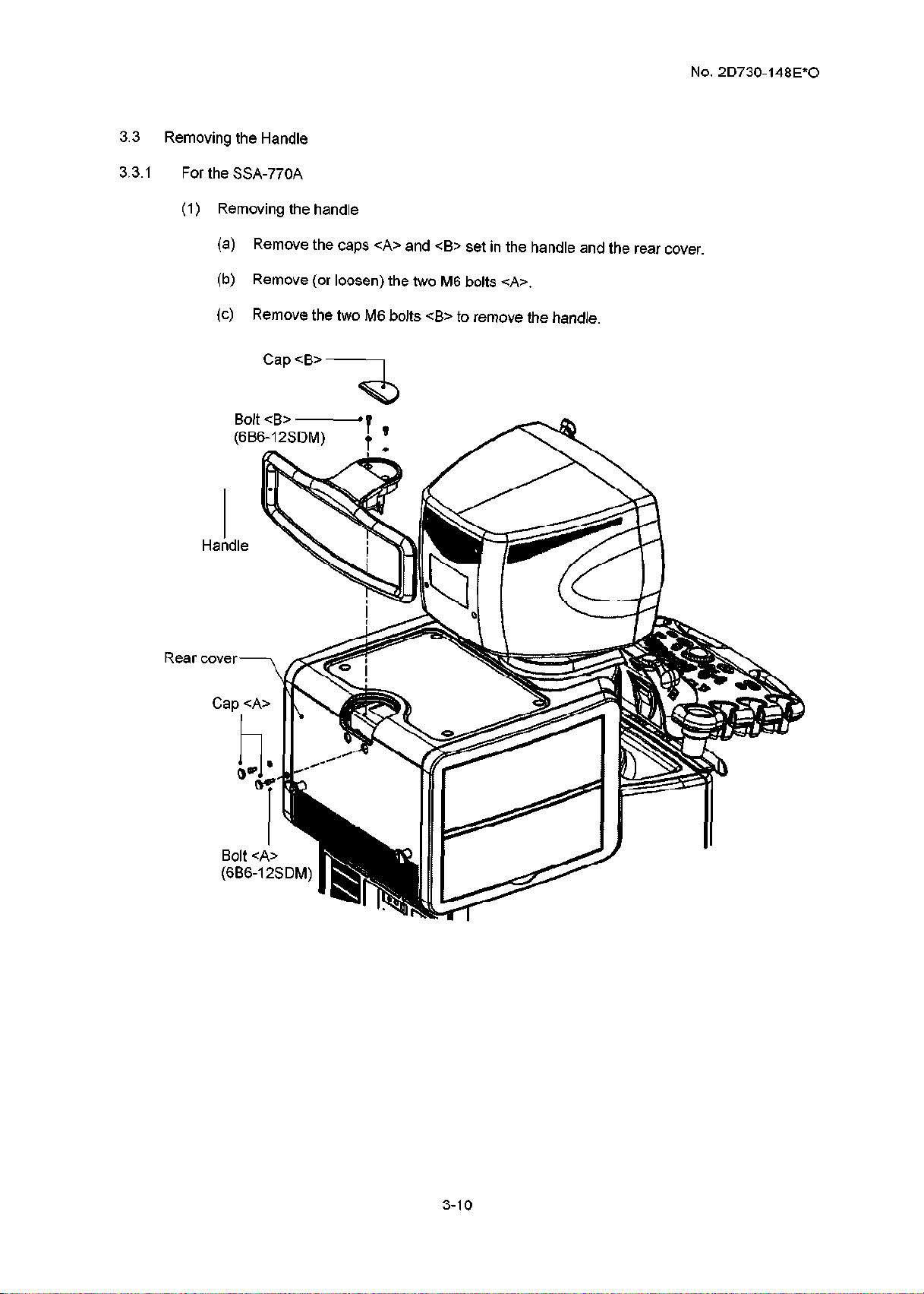
3.3
Removing the Handle
No. 2D730-148E*O
3.3.1
For the SSA-770A
(1) Removing the handle
(a) Remove the caps <A> and <B> set in the handle and the rear cover.
(b) Remove (or loosen) the two M6 bolts <A>.
(c) Remove the two M6 bolts <B> to remove the handle.
Cap <B> 7
Bolt <B> -
(6B6-12SDM)
Haidle
P
+ ’
Bolt <Ii>
(6B6-12SDM)
I
3-10
Page 28
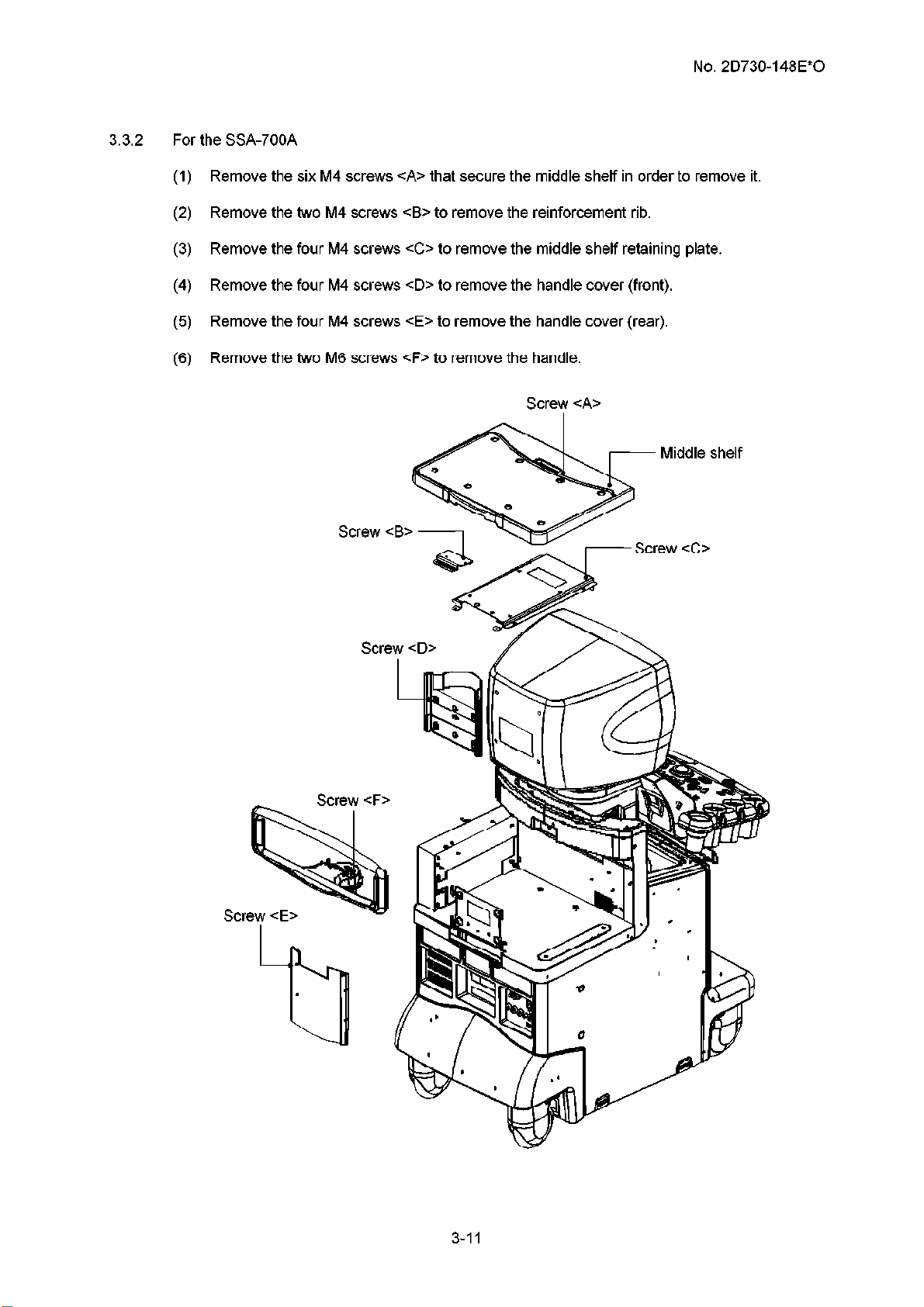
3.3.2 For the SSA-700A
(1) Remove the six M4 screws <A> that secure the middle shelf in order to remove it.
(2) Remove the two M4 screws <B> to remove the reinforcement rib.
(3) Remove the four M4 screws CC> to remove the middle shelf retaining plate.
(4) Remove the four M4 screws CD> to remove the handle cover (front).
(5) Remove the four M4 screws cE> to remove the handle cover (rear).
(6) Remove the two M6 screws cF> to remove the handle.
No. 2D730-148E*O
Screw <A>
Middle shelf
Screw cB>
Page 29
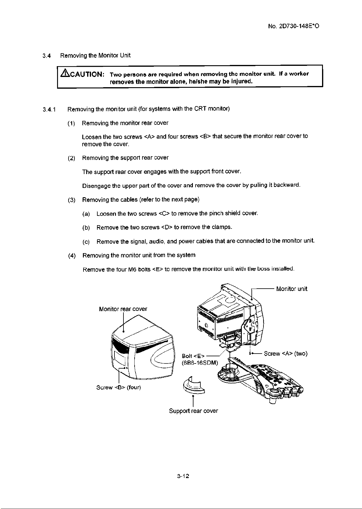
Removing the Monitor Unit
3.4
No. 2D730-148E*O
hAUTION: T
3.4.1 Removing the monitor unit (for systems with the CRT monitor)
(1) Removing the monitor rear cover
Loosen the two screws CA> and four screws cB> that secure the monitor rear cover to
remove the cover.
(2) Removing the support rear cover
The support rear cover engages with the support front cover.
Disengage the upper part of the cover and remove the cover by pulling it backward.
(3) Removing the cables (refer to the next page)
(a) Loosen the two screws CC> to remove the pinch shield cover.
(b) Remove the two screws CD> to remove the clamps.
(c) Remove the signal, audio, and power cables that are connected to the monitor unit.
wo persons are required when removing the monitor unit. If a worker
removes the monitor alone, he/she may be injured.
(4) Removing the monitor unit from the system
Remove the four M6 bolts <E> to remove the monitor unit with the boss installed.
- Screw <A>
I
Support rear cover
(two)
3-12
Page 30
No. 2D730-148E*0
n
Signal cable
Clamp (for signal
and audio cables)
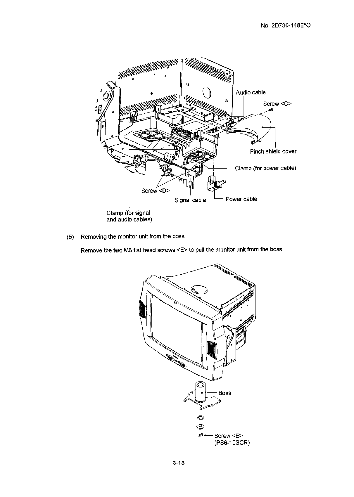
Removing the monitor unit from the boss
(5)
Remove the two M6 flat head screws cE> to pull the monitor unit from the boss.
Audio cable
’
4
Pinch shield cover
Power cable
Screw CC>
(for power cable)
3-13
- Screw cE>
(PS6-1 OSCR)
Page 31

3.4.2 Removing the monitor unit (for systems with the LCD monitor)
(1) Remove the screw <A> and then remove the connector cover.
(2) Disconnect the power cable, DVI cable, and audio cable.
(3) Attach the connector cover and secure it with the screw <A>.
* The screw <A> is a self-tapping screw. Special care is required when tightening it.
(4) Remove the four caps and the four M4 screws cB> to remove the speakers (one each on
the right and left of the monitor).
(5) Remove the two M4 screws ~0.
(6) Loosen the two M4 screws CD> and then remove the LCD monitor from the arm.
Power cable -/5
-Connector cover
LCD monitor
No. 2D730-148E”0
Screw CD>
(SBPPCI OSCR)
opaa~er (one eacn
on the right and
leftof the monitor)
(Velcro fastener is
provided on the monitor.)
(SBPPClPSCRM\ 0
Screw
<A>
\-
-LCD monitor arm
3-14
Page 32

No. 2D730-148E*O
3.4.3
Removing the LCD monitor arm
Remove the two caps and the two M3 screws <A> to remove arm cover I.
(1)
Remove the two M3 screws <B> to remove arm cover 2.
(2)
(3) Remove the two M3 screws CC> to remove arm base cover I.
(4) Raise the stopper and remove the M3 screw CD> and the M3 screw cE>.
Arm cover 1
Arm cover 2
IL
Stopper
Arm base cover
*Screw
-Screw cc;=(PS3-8SCR)
1
+,‘,,,
3-15
Page 33

No. 2D730-148E*O
(5) Rotate the arm biaxial rotation column in the direction indicated by the arrow in the figure
below. Lift arm base cover 2 to separate it from the stopper.
Arm base cover 2 I
Biaxial rotation column
(6) Remove the two M3 screws <F> and the clamps cG> and <Hz.
(7) Remove the three M4 screws cl> and the clamps cJ>, cK>, and CL>.
Screw cF>
Clamp cG>
I
Screw <I>
(SBPP4-1
P3-8SCR)
Yamp cH’
Remove the cables one by one from the LCD monitor arm to the base
(8)
3-16
Page 34

No. 2D730-148E*0
(9) Push in the neck of the support rear cover to disengage it from the support front cover and
remove it.
(10) Remove the two M4 screws <A> to remove the support front cover.
(11) Remove the four M6 bolts <B> to remove the LCD monitor arm.
(12) Lift the LCD monitor arm and remove the three monitor cables from the arm
Screw ==:A>
(SBPP4-?2SCR)
Support front cover-
3perating panel 1
-Support rear cover
3-17
Page 35

3.4.4 Adjusting the LCD monitor arm vertical movement resistance
(1) Remove the two caps and the two M3 screws <A> to remove arm cover I.
(2) Remove the two M3 screws <B> to remove arm cover 2.
No. 2D730-148E*O
Screw cB>
(PS3-8SCR)
- Arm cover 2
(3) Using the M6 hex key, rotate the hexagonal socket head bolt to adjust the vertical
movement resistance of the LCD monitor arm.
Reducing the LCD monitor vertical
Increasing the LCD monitor
vertical movement resistance
1
movement resistance
I
Id bolt
3-18
Page 36

3.5 Removing the Operating Panel
3.5.1 For the SSA-770A
The operating panel must be raised using the up/down slide lever in advance.
Removing the handle
(1)
Refer to subsection 3.3.
Removing the monitor unit
(2)
Refer to subsection 3.4.
Removing the right side cover
(3)
(a) Remove the two rubber caps at the bottom of the cover.
(b) Remove the two M4 screws CA> to remove the cover.
* The cover can be removed by pulling its bottom toward you.
No. 2D730-148E*O
Removing the left side cover
(4)
(a) Remove the two rubber caps at the bottom of the cover.
(b) Remove the two M4 screws cB> to remove the cover.
* The cover can be removed by pulling its bottom toward you.
Removing the right side cover for the peripheral units
(5)
Remove the two M4 screws ~0 to remove the cover.
* The cover can be removed by lifting it and pulling it toward you.
Removing the left side cover for the peripheral units
(6)
Remove the two M4 screws CD> to remove the cover.
* The cover can be removed by lifting it and pulling it toward you.
Removing the transducer cable arm
(7)
Remove the two M4 bolts cE> to remove the transducer cable arm.
Removing the transducer cable hook
(8)
Remove the two M4 bolts cF> to remove the transducer cable hook.
Removing the top cover
(9)
(a) Remove the four caps.
(b) Remove the four M4 screws <G> to remove the cover.
Removing the support front cover
(10)
Remove the two M4 screws <H> to remove the cover.
3-19
Page 37

No. 2D730-148E*0
Left side cover
I
PP4-12SCR) ‘l.,
(SB
Support front cover
\
Left side
0
t
0
1
Screw cH>
(SBPP4-12SCR1_ T
Cap
Screw <G=(SBPP4-12SCR)
Transducer cable arm
(1 I)
Removing the bellows
Remove the two M4 screws <I>.
(12) Removing the front/rear sliding wire
(a)
Remove the M3 screw cJ> to remove the retaining clamp for the front/rear sliding
wire.
(b)
Loosen the screw cK> and rotate the wire retaining bracket to remove the end of the
wire.
(c) Rotate the wire to remove it from the up/down mechanism.
TRight side cover
‘\
‘\
‘\
-\
‘1
Screw CA>
(SBPP4-12SCR)
3-20
Page 38

(13)
Removing the up/down sliding wire
(a)
Remove the end of the wire from the lever.
(b)
Rotate the wire to remove it from the up/down mechanism.
No. 2D730-148E*O
Up/down sliding wire 1
Up/down sliding mechanism
,,----,
Front/rear sliding wire
Screw
(SBPF
Cl>
‘4-l 2SCR)
I
Wire retaining bracket
Front/rear sliding wire
3-21
Page 39

No. 2D730-148E*O
(14) Removing the cables
Remove the connected cables and the M3 screw CL> to remove the USB fitting clamp.
Screw CL>
(SBPP3-IOSCR)
Clamp
(15) Remove the operating panel from the system
(a) Remove the four M6 bolts CM>.
(b) Loosen the two M6 screws <N>. Rotate the operating panel clockwise and lift it to
remove it.
3-22
Page 40

3.5.2 For the SSA-700A
(1) Removing the handle
Refer to subsection 3.3.1.
(2) Removing the monitor unit
Refer to subsection 3.4.
(3)
Removing the right side cover
Same as for the SSA-770A.
(4)
Removing the left side cover
Same as for the SSA-770A.
(5) Remove the screw CA> to remove the cover cl>.
(6) Remove the screws cB> and CC> to remove the covers <2> and <3>
No. 2D730-148E*O
(7) Remove the screw CD> to remove the cover <4>.
(8) Remove the screw cE> to remove the cover <!?I>
I Covercl>
Cover <5>
Screw cE>
3-23
Page 41

3.6 Disassembling the Operating Panel
3.6.1 Removing the lower cover
(1) Remove the transducer holders (six), jelly holders (two), and knobs (four small and one
large).
Jelly holder
No. 2D730-148E*O
I
(small)
(2) Remove the four screws <A> from the right and left of the holder mounting
on the back of the panel.
Screws CA>
base secured
- Screws CA>
3-24
Page 42

No. 2D730-148E*O
Loosen the four screws cB> at the right and left of the holder mounting base.
(3)
* The screws B include springs and cannot be removed. Loosen the screws so that they
turn freely and protrude from the base.
3-25
Page 43

No. 2D730-148E*O
Hold the cover at the jelly holder mounting holes, apply a force so as to pull the cover
(4)
toward you, and lift the cover to remove it.
&AUTION: Th e cover is mounted by engaging the indentations in its front part
with the tabs in the handle section. Therefore, do not attempt to
remove the cover by lifting it from the front. Doing so may
damage the cover.
Pull the cover
3-26
Page 44

No. 2D730-148E*O
3.6.2
Removing the upper panel
(1) Remove the two screws <A> and the three screws cB> and shift the panel in the direction
indicated by the arrow.
Screws CA>
Remove the two connectors
(2)
3-27
Page 45

No. 2D730-148E*0
3.6.3
Removing the handle
(1) Remove the five screws <A> on the back of the panel and remove the handle.
Screws <A>
3-28
1
Handle
Page 46

3.6.4 Removing the trackball section
(1) Remove the connector connected to the trackball section and remove the trackball section.
No. 2D730-148E*O
Trackball section
Connector
3-29
Page 47

3.6.5 Removing the PWBs (B) and (G)
(1) Remove the three connectors connected to the PWB (B).
(2) Remove the twelve screws <A> and remove the PWB (B).
(3) Remove the two screws cB> and remove the PWB (G).
Connector PWB (B)
No. 2D730-148E*O
Screw
(indica
<A>
[ted by a * mark)
/
/ v
Pm 0
Screws <B>
Connectors
3-30
Page 48

3.6.6 Removing the keyboard
Remove the six flat head screws CA> and shift the keyboard.
(1)
(2) Remove the connector.
Screws CA> Screws <A>
No. 2D730-148E*O
Page 49

3.6.7 Removing the keyboard
(1) Remove the five screws CA> and the two screws <B> and remove the keyboard plate B.
(2) Remove the connectors from the FPC.
(3) Remove the six screws CC> and remove the keyboard cover.
No. 2D730-148E*O
Screws CA>
(4) Remove the keyboard.
Keyboard cover
Screws CC>
Keyboard
3-32
Page 50

3.6.8 Removing the LCD ASSY
Remove the USB rubber cap.
(1)
Remove the two connectors.
(2)
(3) Remove the two screws <A> and remove the L-bracket L and the L-bracket R.
(4) Remove the five screws <B> and remove the LCD ASSY.
No. 2D730-148E*O
Screw cB>
Connector
LCD ASSY
Screws cB>
i
USB rubber
cap
3-33
Page 51

3.6.9 Removing the PWBs (C), (D), and (E)
(1) Remove the six knobs CA>, <B>, and CC> and the eight STC slide controls CD>.
Kno
No. 2D730-148E*O
Remove the two connectors.
(2)
Remove the five screws <A> and remove the PWB (C).
(3)
Remove the eleven screws <B> and remove the PWB (D).
(4)
Remove the two screws CC> and remove the PWB (E).
(5)
Screws CC>
Screws <B>
A
pwy CC)
Screws <A>
Screis <B>
Screws <A>
Conn\ector
3-34
Page 52

3.6.10 Removing the near/away slide lever
(1) Remove the two screws CA> and remove the clamp.
(2) Remove the two screws cB> and remove the bracket.
(3) Remove the two screws CC> and remove the lever.
(4) Remove the two screws CD> and remove the wire.
Screws CA>
No. 2D730-148E*O
*acket
3-35
Page 53

3.6.11 Removing the up/down slide lever
* Only for the SSA-770A
(1) Remove the screw <A> and remove the clamp.
(2) Remove the two screws <B> and remove the up/down slide lever.
No. 2D730-148E”0
Screw CA> -
3-36
Page 54

No. 2D730-148E*O
3.6. 12
Mounting the switch cover
(1) Mount the cover (starting with the front section) by reversing the steps for removal.
Engage the tabs in the handle section with the indentations in the cover cl> and then
mount the cover c2>.
(2) Secure the four screws cB> while pressing the cover from above.
(3) Secure the four screws <A> at right and left of the holder mounting base on the back of
the panel.
(4) Install the four small rotary encoder knobs and the large rotary encoder knob.
Tabs
Page 55

Removing the PWB Rack
3.7
1 ACAUTION: Two persons are required when removing the PWB rack.
Confirm that the transducers have been removed.
(1) Removing the left side cover
(a) Remove the two rubber caps at the bottom of the cover.
(b) Remove the two M4 screws <A> to remove the cover
* The cover can be removed by pulling its bottom toward you
(2) Removing the AC-DC metal retainer
(a) Loosen the two M4 screws cB> to remove the AC-DC metal retainer.
No. 2D730-148E*O
Screw <A> p’
(SBPP4-12SCR)
AC-DC metal retainer
Left side cover
3-38
Page 56

(3)
Removing the right side cover
(a) Remove the two rubber caps at the bottom of the cover.
(b) Remove the two M4 screws CC> to remove the cover.
* The cover can be removed by pulling its bottom toward you.
(4) Removing the right side cover for the peripheral units
Remove the two M4 screws CD> to remove the cover.
* The cover can be removed by lifting it and pulling it toward you.
(5) Removing the PWB rack
(a) Remove all the cables connected to the PWB rack.
(b) Remove the two M4 screws cE> and extract the PWB rack.
No. 2D730-148E*O
(SBPP4-12SCR)
Right side cover for
the peripheral units
Screw CC>(SBPPC12SCR)
3-39
Page 57

3.8 Removing the PWBs
(1) Removing the right side cover
(a) Remove the two rubber caps at the bottom of the cover.
(b) Remove the two M4 screws <A> to remove the cover.
* The cover can be removed by pulling its bottom toward you.
(2) Removing the PWBs
(a) Loosen the four screws cB> to remove the PWB rack shield plate.
(b) Release the card ejectors at the upper and lower ends of the PWB and extract the PWB.
No. 2D730-148E*O
PWB rack
cover
(SBPPC12SCR)
Page 58

3.9 Removing the TI
Confirm that the transducers have been removed.
(1) Removing the right side cover
(a) Remove the two rubber caps at the bottom of the cover.
(b) Remove the two M4 screws <A> to remove the cover.
* The cover can be removed by pulling its bottom toward you.
(2) Removing the TI
(a) Remove the cable for the pencil transducer (PP) connected to the TI.
(b) Loosen the two screws cB> to extract the TI.
No. 2D730-148E*O
cover
3-41
Page 59

3.10 Removing the IO
(1) Removing the right side cover
(a) Remove the two rubber caps at the bottom of the cover.
(b) Remove the two M4 screws <A> to remove the cover.
* The cover can be removed by pulling its bottom toward you.
(2) Removing the IO
(a) Remove all the cables connected to the IO
(b) Loosen the two screws <B> to extract the IO.
No. 2D730-148E*O
Screw cB> (two)
(SBPP4-12SCR)
Right side cover
3-42
Page 60

3.11 Removing the HDD Unit
(1) Removing the left side cover
(a) Remove the two rubber caps <A> at the bottom of the cover.
(b) Remove the two M4 screws <A> to remove the cover.
* The cover can be removed by pulling its bottom toward you.
(2)
Removing the right side cover
(a) Remove the two rubber caps cB> at the bottom of the cover.
(b) Remove the two M4 screws cB> to remove the cover.
* The cover can be removed by pulling its bottom toward you.
(3) Remove the power supply section rear cover
No. 2D730-148E*O
Remove the four M4 screws CC> to remove the
(4) Removing the HDD unit
Remove the four M4 screws CD> to remove the
Right
cover.
HDD unit
Left side cover
Screw <A=(SBPP4-12SCR)
Power supply
section rear cover
(SBPP4-12SCR)
Screw CC>
(SBPP4-12SCR)
3-43
Page 61

3.12 Removing the Battery
(1) Removing the left side cover
(a) Remove the two rubber caps at the bottom of the cover.
(b) Remove the two M4 screws <A> to remove the cover.
* The cover can be removed by pulling its bottom toward you.
(2) Removing the battery
(a) Remove the battery connector that is connected to the AC-DC unit.
(b) Remove the battery of the AC-DC unit.
No. 2D730-148E*O
(SBPP4-12SCR)
Left side cover
3-44
Page 62

3.13 Removing the AC-DC Unit
(1) Removing the left side cover
(a) Remove the two rubber caps at the bottom of the cover.
(b) Remove the two M4 screws <A> to remove the cover.
* The cover can be removed by pulling its bottom toward you.
(2) Removing the AC-DC unit
(a) Remove all the cables connected to the AC-DC unit.
(b) If the metal sheet for EMC compliance is installed, remove it by removing screws cB>.
(c) Remove the four M4 screws CC> to remove the AC-DC unit.
No. 2D730-148E*O
Screw <A> J
(SBPP4-12SCR)
Metal sheet for
EMC compliance
Screw cB>
(SBPP3-8SCR)
Left side cover
Cap
3-45
Page 63

No. 2D730-148E*O
CAUTION: When replacing the AC/DC tray of the SSA-770A, check the revision number of the AC/DC
tray supplied for replacement and follow the appropriate procedure according to the
revision number.
1. When the new AC/DC tray is BSM31-2013E (no revision)
The AC/DC tray is not compatible and must not be used to replace the existing tray.
2. If AC/DC tray BSM31-2013E-G or BSM31-2013E-I is supplied
(1) Wind the cables around the core as described below.
Wind the FAN/RELAY signal cables (two lines) between the AC/DC tray and
(a)
transformer tray ONE time around the core (TWO turns).
* When the cable is passed through the core the first time it is counted as
one turn. Therefore, winding of the cable one time corresponds to TWO
turns.
Wind the LED signal cable (which is connected to the top of the AC/DC tray)
(b)
between the AC/DC tray and the transformer tray ONE time around the core
(TWO turns).
* When the cable is passed through the core the first time it is counted as
one turn. Therefore, winding of the cable one time corresponds to TWO
turns.
(2) The metal sheet for EMC compliance should not be installed.
1) (b) Core for the LED signal cable
Wind the cable ONE time around
the core (TWO turns).
%
%
0
0
0
0
(1) (a) Core for the FAN/RELAY
signal cable
Wind the cable ONE time around
the core (TWO turns).
3-46
Page 64

No. 2D730-148E*O
CAUTION: 3. When the new AC/DC tray is BSM31-2013E-H or-J or later (revision or later)
(1) Wind the cables around the core as described below. Note the number of times
each cable is to be wound around the core.
(a) Wind the FAN/RELAY signal cables (two lines) between the AC/DC tray and
transformer tray FOUR times around the core (FIVE turns).
* When the cable is passed through the core the first time it is counted as
one turn. Therefore, winding of the cable four times corresponds to five
turns.
(b) Wind the LED signal cable (which is connected to the top of the AC/DC tray)
between the AC/DC tray and the transformer tray ONE time around the core
(TWO turns).
* When the cable is passed through the core the first time it is counted as
one turn. Therefore, winding of the cable one time corresponds to TWO
turns.
(2) The metal sheet for EMC compliance should be installed.
Press the metal sheet firmly against the rack so that the upper tab is flat and then
secure the sheet using screws1 and 2.
(2) Press the metal sheet for EMC compliance firmly
against the rack so that this tab is flat and then
secure the sheet using screws 1 and 2.
/;1) (b) Core for the LED signal cable
Wind the cable ONE time around
the core (TWO turns).
(1) (a) Core for the FAN/RELAY
Wind the cable FOUR times around
the core (FIVE turns).
\I----:.:,
Screw
(M3*8 mm)
\
Screw
(M3*8 mm)
3-47
Page 65

3.14 Removing the PSA and PSD
Removing the left side cover and AC-DC unit
(1)
Refer to subsection 3.13.
Removing the FAN-BOX
c-3
(a)
Remove the cable of the FAN-BOX (P95).
(b) Loosen the three M3 FAN-BOX mounting screws CA> that secure the PSA and PSD to
remove the FAN-BOX.
Removing the PSA
(3)
Loosen the three screws <B> and two screws CC> that secure the PWB rack, hold the
handles at the upper and lower ends, and extract the PSA.
Removing the PSD
(4)
Loosen the two screws CD> and the screw cE> that secure the PWB rack, hold the handles
at the upper and lower ends, and extract the PSD.
No. 2D730-148E*O
Screw <E>
3-48
Screw cB>
Sc;kw cA>
(SBPP3-IOSCR)
Page 66

3.15 Removing the Transformer
Removing the left side cover
(1)
(a) Remove the two rubber caps <A> at the bottom of the cover.
(b) Remove the two M4 screws <A> to remove the cover.
* The cover can be removed by pulling its bottom toward you.
Removing the right side cover
(2)
(a) Remove the two rubber caps cB> at the bottom of the cover.
(b) Remove the two M4 screws cB> to remove the cover.
* The cover can be removed by pulling its bottom toward you.
Removing the power supply section rear cover
(3)
Remove the four M4 screws CC> to remove the cover.
No. 2D730-148E*O
Removing the base rear cover
(4)
Loosen the two M4 screws <D> to remove the cover.
* The cover can be removed by pulling it toward you slightly and lifting it obliquely.
Removing the transformer
(5)
(a) Remove all the cables connected to the transformer.
(b) Remove the four M4 screws cE> to extract the transformer.
(SBPP4-12SCR)
section rear c
Left side
Base rear
Screw CD>
(SBPP4-12SCR)
I
Screw CC> Screw <A> -’
(SBPP4-12SCR) (SBPP4-12SCR)
Cap CA>
3-49
Page 67

3.16 Removing the MO
(1) Removing the cables
(a) Remove the two rubber caps at the bottom of the left side cover.
(b) Remove the two M4 screws <A> to remove the left side cover.
(c) Remove the four M3 screws <B> to remove the internal cover.
(d) Remove the internal SCSI cable (J505) and power cable (J502 or J503) that are
connected to the MO.
(2) Removing the MO
(a) Remove the blank cover.
Remove the two M3 screws CC> to extract the MO
(b)
No. 2D730-148E*O
Left side cover
Cap
Screw CA>
(SBPP4-12SCR)
:R)
I
3-50
Page 68

3.17 Removing the Front Panel
3.17.1 For the SSA-770A
Removing the left side cover
(1)
(a) Remove the two rubber caps CA> at the bottom of the cover.
(b) Remove the two M4 screws <A> to remove the cover.
* The cover can be removed by pulling its bottom toward you.
Removing the right side cover
(2)
(a) Remove the two rubber caps cB> at the bottom of the cover.
(b) Remove the two M4 screws cB> to remove the cover.
* The cover can be removed by pulling its bottom toward you.
Removing the left side cover for the peripheral units
(3)
No. 2D730-148E*O
Remove the two M4 screws CC> to remove the cover.
* The cover can be removed by lifting it and pulling it toward you.
Removing the left side cover for the peripheral units
(4)
Remove the two M4 screws CD> to remove the cover.
* The cover can be removed by lifting it and pulling it toward you.
Removing the tray
(5)
Loosen the four M4 screws <E> to remove the tray.
Removing the top front cover
(6)
Remove the four M4 screws cF> to remove the cover.
3-51
Page 69

No. 2D730-148E”0
Right side cover for
the peripheral units
Left side cover for
the peripheral
units
Cap
7
(SBPPCI 2SCR)
<F>
(SBPP4-12SCR)
L
Screw <A>
(SBPPCI 2SCR)
- Screw
Screw <E>
(SBPPCI 2SCR)
3-52
Page 70

Removing the cables connected to the MO
(7)
Remove the four M3 screws cG> to remove the internal cover.
Remove the internal SCSI cable (J505) and power cable (J502 or J503) that are
connected to the MO.
Remove the cables (J67, J68, J400, and J132) connected to the front panel.
Removing the front panel
63)
Remove the four M4 screws cH> to remove the front panel.
No. 2D730-148E*O
Internal cover -
Screw <G>
(PS3-GSCR)
/
.MO
3-53
Page 71

3.17.2 For the SSA-700A
(1) Removing the right side cover
Same as for the SSA-770A.
(2) Removing the left side cover
Same as for the SSA-770A.
(3) Removing the tray
Same as for the SSA-770A.
(4)
Remove the screw <A> to remove the middle shelf.
(5) Remove the screw cB> to remove the cover cl>.
(6) Remove the screws CC> and CD> to remove the covers <2> and c3>.
(7) Remove the screw cE> to remove the front cover.
No. 2D730-148E*O
- Screw CA>
1 Covyrcl>
y, * : II
Front cover
I
- Screw cE>
Screw CC>
I
$- Cover <2>
Trpy
3-54
Page 72

No. 2D730-148E*O
3.18
Removing the Rear Panel
Removing the left side cover
(1)
(a) Remove the two rubber caps CA> at the bottom of the cover.
(b) Remove the two M4 screws <A> to remove the cover.
* The cover can be removed by pulling its bottom toward you.
(2) Removing the right side cover
Remove the two rubber caps cB> at the bottom of the cover.
(a)
(b) Remove the two M4 screws cB> to remove the cover.
* The cover can be removed by pulling its bottom toward you.
Removing the power supply section rear cover
(3)
Remove the four M4 screws CC> to remove the cover.
(4) Removing the cables
Remove all the cables connected to the rear panel.
(5) Removing the rear panel
Remove the two M3 screws CD> to remove the rear panel.
section
rear cover
Screw CC>
(SBPP4-12SCR)
L Screw CD>
(SBPP3-1 OSCR)
Left side cover
\
Screw CA>
(SBPP4-12SCR)
Cap CA>
3-55
Page 73

3.19 Removing the PHYSIO Unit
3.19.1 For the SSA-770A
Removing the right side cover
(1)
(a) Remove the two rubber caps at the bottom of the cover.
(b) Remove the two M4 screws <A> to remove the cover.
* The cover can be removed by pulling its bottom toward you.
Removing the right side cover for the peripheral units
(2)
Remove the two M4 screws cB> to remove the cover.
* The cover can be removed by lifting it and pulling it toward you.
Removing the metal fitting
(3)
Remove the three M3 screws CC> to remove the metal fitting.
No. 2D730-148E*O
Removing the PHYSIO unit
(4)
(a) Remove all the cables connected to the PHYSIO unit.
(b) Remove the M4 screw CD> and M4 screw cE> to remove the PHYSIO unit.
Screw CD> 1
(PTR4-IOSBNI)
Metal fitting \
Right side cover for
the peripheral units
Right side cover
-Screw cB>
(SBPP4-12SCR)
Screw <A>
(SBPP4-12SCR)
Cap
3-56
Page 74

3.19.2 For the SSA-700A
(1) Removing the right side cover
Same as for the SSA-770A.
(2) Removing the PHYSIO unit
(a) Disconnect all cables that are connected to the PHYSIO unit.
(b) Remove the screw CA> to remove the middle shelf.
(c) Remove the screw cB> at the PHYSIO unit to remove the PHYSIO front cover,
(d) Remove the PHYSIO unit.
No. 2D730-148E*O
! shelf
Screw <
:A>
PHYSIO unit
Page 75

3.20 Removing the Caster Units
3.20.1 For the SSA-770A
Removing the left side cover
(1)
(a) Remove the two rubber caps CA> at the bottom of the cover.
(b) Remove the two M4 screws <A> to remove the cover.
* The cover can be removed by pulling its bottom toward you.
(2) Removing the right side cover
(a) Remove the two rubber caps cB> at the bottom of the cover.
(b) Remove the two M4 screws cB> to remove the cover.
* The cover can be removed by pulling its bottom toward you.
Removing the front cover (required to remove the front caster unit)
(3)
No. 2D730-148E*O
(a) When the blank cover has been mounted, loosen the M3 screw CC> and remove the
blank cover with the printer base.
(b) Remove the four M4 screws CD> to remove the cover.
(4) Removing the power supply section rear cover (required to remove the rear caster unit)
Remove the four M4 screws CD> to remove the cover,
Removing the base front cover (required to remove the front caster unit)
(5)
(a) Remove the two M4 screws cF>.
(b) Loosen the two M4 screws cG> to remove the cover.
* The cover can be removed by pulling it toward you slightly and lifting it obliquely.
(6) Removing the base rear cover (required to remove the rear caster unit)
Loosen the two M4 screws cH> to remove the cover.
* The cover can be removed by pulling it toward you slightly and lifting it obliquely.
3-58
Page 76

Left side cover
No. 2D730-148E*O
r Right side cover
Cap cB>
crew cB>
(SBPP4-12SCR)
.
- Front cover
(SBPP4-12SCR)
/
2SCR)
I
Base front cover
LScrew CD>
(SBPP4-12SCPj
L screw cG>
(SBPP4-12SCR)
Blank cover
*/
3-59
Page 77

No. 2D730-148E*O
(7) Removing the blocks
Remove the four M4 bolts <I> to remove the two blocks supporting the shaft of the caster
unit.
(8) Removing the caster units
(a) Remove the eight M4 screws cJ>.
(b) Remove the eight M8 screws cK> and remove the caster unit by sliding it toward the
front of the system.
* Remove the caster unit at the rear of the system using the same procedure.
Screw cJ>
(SBPP4-IGSCR)
Block
1’
1.
I
Caster unit /
(6B8-20SDM)
3-60
Page 78

No. 2D730-148E*O
3.20.2
For the SSA-700A
(1) Follow the same procedures as for the SSA-770A until the base covers are removed.
(2) Remove the eight caster fixing screws (four each on the right and left casters, M8).
Caster
I
Caster fixing
3-61
Page 79

3.21 Cleaning the Air Filters
(1) Removing and cleaning the air filters (for service engineers)
(a) Remove the two M4 screws to extract both the front and rear filters.
(b) Remove the dust from the meshes using a vacuum cleaner.
(c) Reinstall the filters by reversing the steps for removal.
No. 2D730-148E*O
Air filter J
(2) Removing and cleaning the air filters (for the user and service engineers)
(a) Remove the filter cover and then remove the air filter.
(b) Remove the dust from the mesh using a vacuum cleaner.
(c) Reinstall the air filters by reversing the steps for removal.
CAUTION: Do not start the system with the filters removed.
3-62
Page 80

3.22 Cleaning the Panel
3.22.1 Cleaning of key tops
(1) Remove dirty key tops by pressing them downward from the surface of the panel.
(2) Clean the removed key tops.
(3) After cleaning, insert the removed key tops from the back of the panel.
CAUTION: Use water or mild detergent to clean the key tops. Completely wipe off the
water from the key tops before reinstalling them. Do not use chlorine-based
cleansers, acids, or organic solvents.
Also, be sure to reinsert the key tops at their original positions with correct
orientations. There is a possibility of reinserting the key tops incorrectly.
3.22.2 Cleaning procedures for parts other than key tops
Use a clean dry cloth for cleaning other parts. If dirt is difficult to remove, use a cloth that has
been moistened with water or mild detergent and then tightly wrung out.
No. 2D730-148E*O
CAUTION: Do not pour water or mild detergent directly on any parts.
Do not use volatile organic solvents such as benzin or paint thinner or rags
impregnated with chemicals.
3-63
Page 81

3.23 Adjusting the Operating Panel Locking Wire
3.23.1 Adjusting the up/down slide wire
* Only for the SSA-770A
(1) Remove the two caps <A>.
(2) Remove the two screws <A> (M4) and remove the right side cover.
e
cover
No. 2D730-148E*O
Screw <A>
(SBPP4-12SCR)
(3) Loosen the nut.
Rotate the adjuster until the lever contacts the gas spring.
(4)
(5) After adjustment, tighten the nut
Cap.cA>
3-64
Page 82

No. 2D730-148E*O
Gas spring
3-65
Page 83

3.23.2 Adjusting the near/away slide wire
(1) Perform the procedures in subsections 3.6.1 and 3.6.4, and the steps (1) and (2) in
subsection 3.6.5 of subsection 3.6 “Disassembling the Operating Panel”.
(2) Loosen the nut.
(3) When locking cannot be released, loosen the adjuster to adjust the wire.
(4) When locking cannot be performed, tighten the adjuster to adjust the wire.
(5) After adjustment, tighten the nut.
Nut-
No. 2D730-148E*O
3-66
Page 84

3.24 Replacing the Operating Panel Locking Wire
3.24.1 Replacing the up/down slide wire
* Only for the SSA-770A
(1) Removing the covers
(a) Remove the two caps <A>.
(b) Remove the two screws CA> (M4) and remove the right side cover.
(c) Remove the two screws cB> (M4) and remove the right side cover for the
peripheral units.
(d) Remove the two caps cB=-.
(e) Remove the two screws CC> (M4) and remove the left side cover.
(f) Remove the two screws CD> (M4) and remove the left side cover for the peripheral
units.
No. 2D730-148E*O
Left
(g) Remove the four screws cE> (M4) and remove the tray.
(h) Remove the four screws cF> (M4) and remove the top front cover.
Right side cover for
the peripheral units
Screw cB>
Left side cover for
the peripheral units
Right side cover
I
Q
T
Cap <A>
Screw CA>
(SBPPC12SCR)
‘IS
I
Cap’cB>
(SBPP4-12SCR)
Screw cE>
(SBPP4-12SCR)
crew CC>
(SBPP4-12SCR)
3-67
Page 85

Removing the up/down slide wire (at the support unit side)
(a) Loosen the nut.
(b) Remove the wire from the lever.
(c) Rotate the adjuster and remove it from the bracket.
No. 2D730-148E*O
(The monitor and covers
are omitted from figure.)
3-68
Page 86

(3) Removing the monitor unit
No. 2D730-148E*O
! CAUTION:
IA
Loosen the two screws CA> and four screws cB> to remove the monitor rear cover.
(a)
Remove the support rear cover at the rear of the operating panel.
(b)
To remove the support rear cover, slide it backward with holding and pushing the
center part.
Loosen the two screws CC> to remove the pinch shield cover.
cc>
Remove the two screws CD> to remove the clamps.
(4
Remove the signal, audio, and power cables that are connected to the monitor unit.
(e)
Remove the four M6 bolts cE> to remove the monitor unit with the boss installed.
0-J
Remove the two M4 screws cF> to remove the support front cover.
(9)
Two persons are required when removing the monitor unit.
3-69
Page 87

t \
I
Screw <B>
D”ll NC’
I^_^ .---nn”\
No. 2D730-148E*O
Screw <A>
Support front cover
Support rear cover
Screw CD>
Clamp
cable
- Screw CC>
- Pinch shield cover
Signal cable
3-70
Page 88

No. 2D730-148E*O
(4) Perform the procedures in subsections 3.6.1 and 3.6.2 of subsection 3.6 “Disassembling
the Operating Panel”.
(5) Removing the up/down slide lever
(a) Remove the screw CA> (M3) and remove the clamp.
(b) Remove the two screws <B> and remove the up/down slide lever.
(6) Replacing the up/down slide wire
Screw <A> -p
*
- Clamp
Install the new up/down slide lever in the operating panel.
(7) Reinstalling the covers
Reinstalling the removed monitor and covers by reversing the steps for removal.
3-71
Page 89

3.24.2 Replacing the near/away slide wire
3.24.2.1 For the SSA-770A
(1) Pull the near/away slide lever of the operating panel toward you to slide the operating
panel and the monitor upward.
No. 2D730-148E*O
3-72
Page 90

(2) Removing the handle
(a) Remove the caps <A> and cB>.
(b) Remove the four bolts <A> (M4) and remove the handle.
Cap <A>
Handle
No. 2D730-148E*O
Bolt <A> ~
(6B4-12SDM)
Cap cB>
3-73
Page 91

(3) Removing the covers
Remove the two caps <A>.
Remove the two screws CA> (M4) and remove the right side cover.
Remove the two screws cB> (M4) and remove the right side cover for the
peripheral units.
Remove the two caps cB>.
Remove the two screws CC=- (M4) and remove the left side cover.
Remove the two screws CD> (M4) and remove the left side cover for the
peripheral units.
Remove the four caps CC>.
(9)
Remove the four screws cE> (M4) and remove the top cover.
(h)
Remove the four screws cF> (M4) and remove the tray.
(0
Remove the four screws cG> (M4) and remove the top front cover.
0)
Left side cover for
the peripheral units
Screw CD>
(SBPP4-12SCR)
Top cover ;
I
No. 2D730-148E*O
Cap CC>
I
-Screw cE>
(SBPPC12SCR)
Left side cover
Screw CC>
(SBPP4-12SCR)
Top front cover
(4) Perform the procedures in subsection 3.4 “Removing the Monitor Unit”
Screw cG>
(SBPP4-12SCR)
Tray
I
I*
.b
-b-
-b
*“1
I
Screw cF>
(SBPP4-12SCR)
II
Right side cover for
the oerioheral units
Screw cB>
(SBPP4-12SCR)
*\**
‘.
L Cap <A>
Screw <A>
(SBPP4-12SCR)
Right side
cover
! CAUTION:
IA
Two persons are required when removing the monitor unit.
3-74
I
Page 92

No. 2D730-148E*O
(5) Removing the near/away slide wire (at the support unit side)
(a) Remove the two screws CA> (M4) and lift the bellows.
(b) Remove the screw cB> (M3) and remove the clamp.
(c) Loosen the screw CC> and rotate the wire retaining bracket to remove the tip of
the wire.
(d) Loosen the nut and rotate the adjuster to remove the wire from the support unit.
Screw cB>
(SBPP3-IOSC
crew <A>
\S
(SBPP4-12SCR)
re
- Support unit
Adjuster
Nut
\
Wire retaining bracket
3-75
Page 93

No. 2D730-148E*O
(6) Perform the procedures in subsections 3.6.1, 3.6.2, 3.6.3, and 3.6.4 and steps (1) and
(2) in subsection 3.6.5 of subsection 3.6 “Disassembling the Operating Panel”.
(7) Removing the near/away slide lever
(a) Remove the two screws CA> and remove the clamp.
(b) Remove the two screws cB> and remove the bracket.
(c) Remove the two screws CC> and remove the lever.
(d) Remove the two screws CD> and remove the wire.
Screws CA>
Clamp
7h
(8) Replacing the near/away slide wire
acket
Install the new near/away slide lever in the operating panel.
(9) Reinstalling the covers
Reinstall the removed monitor and covers by reversing the steps for removal.
3-76
Page 94

3.24.2.2 For the SSA-700A
(1) Removing the monitor unit
Refer to subsection 3.4.
(2) Removing the right side cover
Same as for the SSA-770A.
(3) Removing the left side cover
Same as for the SSA-770A.
(4) Remove the screws <A> and <B> to remove the middle shelf and the metal plate for
retaining the middle shelf.
(5) Remove the screw CC> to remove the cover cl>
(6) Remove the screws CD> and cE> to remove the covers <2> and <3>
No. 2D730-148E*O
(7) Remove the screw cF> to remove the cover c4>.
(8) Remove the screw cG> to remove the cover <5=-.
(9) Remove the screw cH> to remove the tray.
(10) Remove the screw <I> to remove the front cover.
Screw <A>
Middle shelf
the middle shelf
Monitor-
Screw CD>
Cover <2> -
eta1 plate for retaining
“1
Front cover
I
Screw ct
3-77
w
- Cover <3>
Side cover
Page 95

No. 2D730-148E*O
(11) Removing the near/away slide wire (at the support unit side)
(a) Remove the screw CA> (M3) and remove the clamp.
(b) Loosen the screw cB> and rotate the wire retaining bracket to remove the tip of
the wire.
(c) Loosen the nut and rotate the adjuster to remove the wire from the support unit.
Screw CA>
(SBPP3-1 OSCR)
\
3-78
wire retaining bracket
Page 96

No. 2D730-148E*O
(12) Perform the procedures in subsections 3.6.1, 3.6.2, 3.6.3, and 3.6.4 and steps (1) and
(2) in subsection 3.6.5 of subsection 3.6 “Disassembling the Operating Panel”.
(13) Removing the near/away slide lever
(a) Remove the two screws CA> and remove the clamp.
(b) Remove the two screws cB> and remove the bracket.
(c) Remove the two screws CC> and remove the lever.
(d) Remove the two screws CD> and remove the wire.
Screws CA>
Clamp
7h
wire
Screw CD> 7
Screw CC> / _ r
Screw cB>
(14) Replacing the near/away slide wire
acket
Install the new near/away slide lever in the operating panel.
(15) Reinstalling the covers
Reinstall the removed monitor and covers by reversing the steps for removal.
3-79
Page 97

3.25 Removing the CD-R Unit
(1) Remove the cap and the two M4 screws <A> and remove the left side cover.
(2) Remove the blank cover <A>.
(3) Remove the four M3 screws <B> and remove the rack cover.
No. 2D730-148E*O
Screw <B> (SBPP3-8SCR)
- L Screw <A> (SBPP4-12SCR)
(4) Secure the CD-R unit in place using the two M3 screws ~0.
Blank cover CA>
J
3-80
-Screw CC>
(SBPP3-8SCR)
Page 98

(5) Connect the power cable and the SCSl5OP cable to the CD-R unit.
NOTE: Command entry
Execute the following program after the CD-R unit is installed or uninstalled.
(1) Display the Service menu.
(2) Select [Utility] - [Command Line], enter the appropriak command, below and
press [Go].
(a) After the CD-R is installed
D:Wplio\TusSetupScript\EnableCD.cmd
(b) After the CD-R is uninstalled
D:\Aplio\TusSetupScript\DisableCD.cmd
(3) Restart the system.
No. 2D730-148E*O
3-81
Page 99

No. 2D730-148E*O
3.26 Cleaning the MO Drive
When dust or foreign matter in the air adheres to the lens actuator of the MO drive, the
performance of the MO drive may be degraded. Clean the lens actuator periodically using the lens
cleaner specified below.
Note: Use the dedicated lens cleaner specified below.
Product name Fujitsu product number Product number for ordering
Lens cleaner 0240470 CA90002-C980
Open the shutter of the lens cleaner before use and check the condition of the brushes. When the
bristles of the brush have spread, the lens cleaner cannot remove stains or dirt from the lens
completely. In such cases, replace the lens cleaner.
Clean the MO drive using the lens cleaner as outlined below. The cleaning procedure takes
approximately 15 seconds.
(1) Start up the system.
(2) Insert the lens cleaner. The lens cleaner is automatically loaded. Once the lens cleaner is
loaded, the positioner moves forward and backward and the lens is cleaned by the cleaning
brush of the lens cleaner.
(3) After cleaning, the lens cleaner is automatically ejected
3-82
Page 100

3.27 Cleaning the Palm Switch
<<Items required for cleaning>>
l
Gauze
l
Air spray
l
Tweezers
3.27.1 Cleaning procedures for the old-type palm switch
Remove the connector from the panel and remove the palm switch.
(1)
Press the two tabs on the sides of the palm switch and remove the top cover of the palm
(2)
switch. Then, remove the ball.
Disconnect the connection cable between the dial board and the main board.
(3)
Do not forcibly disconnect the cable connector.
Clean the detection shafts and 45” bearing (shaded sections in the figure) with a piece of
(4)
gauze.
No. 2D730-148E*O
(5)
(6)
(7)
(8)
(9)
(10)
(11)
(12)
Clean out the inside of the case using an air spray.
Take appropriate measures to prevent dust from flying out. Check for foreign matter inside
the case.
Clean the dial rotation surface using a cotton swab.
Clean the gap between the dial and the cover (circumference) using the air spray.
Clean the inside of the dial unit using the air spray.
Connect the cable between the dial board and the main board.
Bend the cable so that it does not interfere with the ball.
After cleaning the ball, place it back into the palm switch and reinsert the top cover.
Confirm that there are no abnormalities in ball rotation and dial rotation.
Reconnect the connector to the palm switch and reinstall the palm switch at its original
position on the panel.
3-83
 Loading...