

Page 1
No. 2B771-004EN*M
OPERATION MANUAL
FOR
DIAGNOSTIC ULTRASOUND SYSTEM
MODEL TUS-A500
[FUNDAMENTALS]
(2B771-004EN*M)
CAUTION:
In the USA, federal law restricts this device to sale by
or on the order of a physician.
IMPORTANT!
Read and understand this manual before operating
the equipment. After reading, keep this manual in
an easily accessible place.
TOSHIBA MEDICAL SYSTEMS CORPORATION 2010-2014
ALL RIGHTS RESERVED
Page 2

Introduction
This operation manual describes the operating procedures for the diagnostic ultrasound system
TUS-A500. To ensure safe and correct operation of the system, carefully read and understand
the manual before operating the system.
Trademarks
Windows® is a registered trademark of Microsoft Corporation in the United States and other
countries.
Clorox Healthcare is a trademark of The Clorox Company.
Dispatch® is a registered trademark of The Clorox Company.
Cleanisept® is a registered trademark of Dr. Schumacher GmbH.
Java is a registered trademark of Oracle and/or its affiliates.
APLIO, Dynamic Flow, ApliPure, MicroPure, and TwinView are trademarks of Toshiba Medical
Systems Corporation.
This manual may include trademarks or registered trademarks of other companies.
Note that the trademark symbol "" and the registered trademark symbol "" may or may not
be used in this manual.
IMPORTANT!
1. No part of this manual may be copied or reprinted, in whole or in part,
without prior written permission.
2. The contents of this manual are subject to change without prior notice
and without legal obligation.
3. The contents of this manual are correct to the best of our knowledge.
Please inform us of any ambiguous or erroneous descriptions, missing
information, etc.
No. 2B771-004EN*M
Page 3
Organization of the Operation Manuals
1. Notation Conventions
In this operation manual, the following word is used in addition to the signal words related to the
safety precautions (refer to section 2 "General Safety Information"). Please read this operation
manual before using the system.
NOTE: Indicates reference information that enables more efficient use of the equipment.
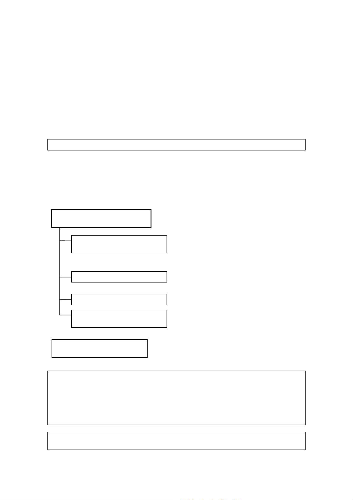
2. Operation Manuals
A TOSHIBA service person or instructor will explain the basic operating procedures for this
system at the time of delivery. However, read this operation manual carefully before using the
system in order to understand the detailed operating procedures, functions, performance, and
maintenance procedures.
Operation manual for the main unit
of the ultrasound system
Fundamentals volume
(this manual)
Applications volume
Measurements volume
Acoustic power and surface
temperature data
Operation manual for each
transducer
..................... Describes the operating and
......... Describes the basic information
concerning the system, such as
preparation for examination, operation,
inspection, and functional descriptions of
the system.
......... Describes the exam data manipulation
procedures and optional unit operation
procedures.
......... Describes the registration and
measurement procedures.
......... Describes the acoustic power
transmitted from the ultrasound
transducer.
disinfection/sterilization procedures for
the transducer.
NOTE: For certain applications, the following manuals are available in English:
2B771-005EN Applications volume
2B771-006EN Measurements volume
2B771-007EN Acoustic power and surface temperature data (For regions other
than the USA)
2B771-008EN Acoustic power and surface temperature data (For the USA only)
2B771-010EN Operation card
NOTE: The operation manuals Applications volume and Measurements volume may be
supplied on electronic media.
No. 2B771-004EN*M
U-1
Page 4

3. Switch Configuration
The descriptions in this operation manual are based on the standard switch configuration. If
the switch configuration has been changed, the differences between the current configuration
and the standard configuration must be understood before use.
The layout, shapes, labels, and icons of the switches on the touch panel can be changed. All
the figures of touch panel and switches in this manual are examples and may differ from the
actual display.
4. Operation Switches
Some operations can be performed using either the switches on the main panel or the
corresponding switches on the touch panel.
The switches displayed on the touch panel differ depending on the selected exam type,
transducer, and mode.
No. 2B771-004EN*M
U-2
* *
Page 5

Table of Contents
Organization of the Operation Manuals ...................................................... U-1
1. Intended Use ..................................................................................... 1-1
1.1 Intended Medical Use .......................................................................... 1-1
1.2 Intended Patient Information .......................................................... 1-1
1.3 User Profile
1.4
Operating Principles ............................................................................. 1-1
.................................................................................................. 1-1
2. General Safety Information ........................................... 2-1
2.1 Meaning of Signal Words .................................................................. 2-1
2.2 Meaning of Safety Symbols ............................................................ 2-1
2.3 Ensuring the Safety of Patients and Operators ................ 2-2
2.4 Preventing Electric Shocks, Fires, and
Power Supply Interruptions
2.5 Chemical Hazard ..................................................................................... 2-5
2.6
Electromagnetic Compatibility (EMC) ...................................... 2-5
2.7 Acoustic Power ........................................................................................ 2-6
............................................................ 2-3
2.8 Preventing System Malfunctions ................................................ 2-7
2.9 Handling Patient and Image Data ................................................ 2-9
2.10 Warning Labels ........................................................................................ 2-9
2.11 Regulatory Labels ................................................................................ 2-12
2.12 Precautions Concerning Clinical
Examination Techniques
No. 2B771-004EN*M
................................................................. 2-13
- a -
Page 6

3. General Information on Usage and
Maintenance ....................................................................................... 3-1
4. Use Conditions .............................................................................. 4-1
4.1 Power and Environmental Requirements ............................. 4-1
4.2 Environmentally Friendly Usage and
Maintenance Management
............................................................... 4-2
5. System Configuration ........................................................... 5-1
5.1 Standard Configuration ...................................................................... 5-1
5.2 List of Optional Units ........................................................................... 5-1
5.3 Compatible Peripheral Devices .................................................... 5-2
5.4 External Storage Devices ................................................................. 5-2
5.5 List of Optional Software .................................................................. 5-3
5.6 List of Available Transducers ........................................................ 5-4
6. Names and Functions of Each Section ........ 6-1
6.1 Name of Each Section ......................................................................... 6-1
6.2 Main Panel ................................................................................................... 6-3
6.3 Rear Panel .................................................................................................... 6-7
6.4 Symbols ......................................................................................................... 6-8
7. Preparation for Examination ....................................... 7-1
7.1 Moving and Installing the System .............................................. 7-1
7.2 Handling and Connecting/Disconnecting the
Transducer
7.2.1 Handling the transducer ............................................................................ 7-4
.................................................................................................. 7-4
No. 2B771-004EN*M
- b -
Page 7

7.2.2 Connecting/Disconnecting the transducer ........................................ 7-4
7.3 Adjusting the Main Panel .................................................................. 7-6
7.4 Adjusting the Monitor .......................................................................... 7-8
7.4.1 Locking and releasing the monitor ....................................................... 7-8
7.4.2 Adjusting the angle of the monitor ........................................................ 7-9
7.4.3 Adjusting the monitor display ............................................................... 7-10
8. Checks Before and After Use ..................................... 8-1
8.1 Checks Before Turning ON the Power .................................... 8-1
8.2 Checks After Turning ON the Power ........................................ 8-2
9. Turning the Power ON/OFF ........................................... 9-1
9.1 Connecting the Power Cable and the
Protective Grounding
9.2 Turning ON the Power ......................................................................... 9-4
9.3 Turning the Power OFF ...................................................................... 9-6
9.4 Standby Mode ........................................................................................... 9-9
9.4.1 Setting Standby mode ................................................................................ 9-9
9.4.2 Recovery from the Standby status ...................................................... 9-11
9.5 Preparation for Use During Surgery or for
Emergency Cases
.......................................................................... 9-2
................................................................................ 9-12
9.5.1 Preparation of a backup system ........................................................... 9-12
9.5.2 Power OFF/ON in the case of system failure ................................... 9-12
10. Basic Screen and Menu ................................................... 10-1
10.1 Display of Various Data Items ..................................................... 10-1
10.2 Displaying the Acoustic Power Data ...................................... 10-2
No. 2B771-004EN*M
- c -
Page 8

10.3 Thumbnail Display ............................................................................... 10-4
11. Starting an Examination .................................................. 11-1
11.1 Entering and Saving Data on the
[Patient Registration] Screen
....................................................... 11-2
12. Reference Signal Display ............................................... 12-1
12.1 Reference Signal Panel .................................................................... 12-4
12.2 Installing the Reference Signal Sensor ................................ 12-5
12.3 Adjusting Reference Signals ........................................................ 12-5
13. Common Operation for Each Mode ................. 13-1
13.1 Touch Panel Operation ..................................................................... 13-1
13.2 Trackball Functions ............................................................................ 13-8
13.2.1 Trackball function area ............................................................................. 13-8
13.2.2 Trackball operations .................................................................................. 13-9
13.3 Selecting an Imaging Preset During Examination ...... 13-10
13.3.1 [DEFAULT PRESET] tab ......................................................................... 13-12
13.3.2 [USER PRESET] tab ................................................................................. 13-15
13.3.3 [Sub Preset] menu .................................................................................... 13-15
13.4 Selecting an Application Preset
During Examination
.......................................................................... 13-16
13.5 Changing the Transducer During
Examination
............................................................................................ 13-18
14. Display and Operation in Each Mode ............ 14-1
14.1 2D Mode ....................................................................................................... 14-1
14.1.1 2D display layout ........................................................................................ 14-1
No. 2B771-004EN*M
- d -
Page 9

14.1.2 Adjustment using the main panel ........................................................ 14-2
14.1.3 Adjustments using the touch panel .................................................... 14-5
14.1.4 Selection of image zooming method .................................................. 14-8
14.1.5 2D mode quick scan ................................................................................ 14-10
14.1.6 Trapezoid scan .......................................................................................... 14-12
14.2 M Mode ....................................................................................................... 14-13
14.2.1 M display layout ........................................................................................ 14-13
14.2.2 Adjustment using the main panel ...................................................... 14-14
14.2.3 Adjustment using the touch panel .................................................... 14-16
14.2.4 FLEX-M mode ............................................................................................. 14-18
14.3 CDI Mode ................................................................................................... 14-20
14.3.1 CDI display layout .................................................................................... 14-20
14.3.2 Adjustment using the main panel ...................................................... 14-21
14.3.3 Adjustment using the touch panel .................................................... 14-23
14.4 Power Angio Mode (Power Mode) .......................................... 14-25
14.4.1 Power Angio display layout .................................................................. 14-25
14.4.2 Adjustment using the main panel ...................................................... 14-25
14.4.3 Adjustment using the touch panel .................................................... 14-26
14.5 Dynamic Flow Mode (ADF Mode) ............................................ 14-28
14.5.1 Dynamic Flow display layout ............................................................... 14-28
14.5.2 Adjustment using the main panel ...................................................... 14-28
14.5.3 Adjustment using the touch panel .................................................... 14-29
14.6 TDI Mode (Tissue Doppler Imaging Mode) ....................... 14-31
14.6.1 TDI display layout ..................................................................................... 14-31
14.6.2 Adjustment using the main panel ...................................................... 14-31
14.6.3 Adjustment using the touch panel .................................................... 14-32
No. 2B771-004EN*M
- e -
Page 10

14.7 Doppler Mode ........................................................................................ 14-34
14.7.1 Doppler display layout ............................................................................ 14-34
14.7.2 Adjustment using the main panel ...................................................... 14-35
14.7.3 Adjustments using the touch panel .................................................. 14-38
15. Cine Function ................................................................................. 15-1
15.1 Overview ..................................................................................................... 15-1
15.2 Cine Operations ..................................................................................... 15-1
16. Body Mark ........................................................................................... 16-1
16.1 Body Mark Entry Mode ..................................................................... 16-1
16.2 Setting and Editing Body Marks ................................................ 16-2
17. Entering Comments .............................................................. 17-1
17.1 Entering Comment Entry Mode .................................................. 17-1
17.2 Entering/Editing Characters and Arrow Marks ............... 17-1
18. Needle Mark ...................................................................................... 18-1
18.1 Applicable Transducers and Biopsy Adapters ............... 18-3
18.2 Needle Mark Display and Angle Change
Procedures
................................................................................................ 18-5
18.2.1 Needle mark display .................................................................................. 18-6
18.2.2 Needle mark angle change procedures ............................................. 18-8
19. Storing Image Data ................................................................. 19-1
19.1 Storing Still Images ............................................................................. 19-1
19.1.1 Operations using the touch panel ....................................................... 19-1
19.2 Storing a Dynamic Image ................................................................ 19-2
No. 2B771-004EN*M
- f -
Page 11

19.2.1 Operations using the touch panel ....................................................... 19-3
19.2.2 Snapshot Clips ............................................................................................ 19-4
19.2.3 Cine Clips (storage of cine image data) ............................................ 19-6
19.2.4 Setting of the storage format (for retrospective storage) .......... 19-8
19.3 File Handling for Image Data ........................................................ 19-8
19.4 Displaying Saved Images ............................................................... 19-8
20. Maintenance ..................................................................................... 20-1
20.1 Technical Descriptions ..................................................................... 20-1
20.2 Outline of Preventive Maintenance .......................................... 20-1
20.3 Preventive Maintenance Performed by the User ........... 20-2
20.3.1 Cleaning the system .................................................................................. 20-2
20.3.2 Disinfecting the system ........................................................................... 20-8
20.3.3 Creating a backup copy of the system hard disk ........................ 20-10
20.3.4 [Maintenance] menu ................................................................................ 20-10
20.3.5 Backing up the customer-specific data (Backup) ....................... 20-11
20.4 Preventive Maintenance Performed by
Service Personnel
.............................................................................. 20-14
20.5 Periodically Replaced Parts and
Consumable Parts
.............................................................................. 20-14
20.6 Checks During Storage .................................................................. 20-14
21. Disposal ................................................................................................. 21-1
22. Checks Before the System
Is Judged Defective ............................................................... 22-1
23. Specifications ................................................................................ 23-1
No. 2B771-004EN*M
- g -
Page 12

23.1 External Dimensions and Mass .................................................. 23-1
23.2 Essential Performance of This System................................. 23-1
23.3 Conformance Standards ................................................................. 23-2
23.4 Safety Classification ........................................................................... 23-3
23.5 Accuracy of Measurement ............................................................. 23-4
24. Using MI/TI ......................................................................................... 24-1
24.1 Using MI/TI (Outside the USA and Canada) ....................... 24-1
24.1.1 Basic knowledge of MI/TI ......................................................................... 24-1
24.1.2 MI/TI display description.......................................................................... 24-3
24.1.3 Parameters affecting the MI/TI values ................................................ 24-4
24.1.4 Operating procedures for MI/TI ............................................................. 24-5
24.1.5 Output display .............................................................................................. 24-6
24.1.6 Reminder ........................................................................................................ 24-6
24.1.7 Ultrasonic output power and acoustic output ................................ 24-7
24.1.8 References for MI/TI ................................................................................... 24-8
24.2 Using MI/TI (in the USA and Canada) ..................................... 24-9
24.2.1 Basic knowledge of MI/TI ......................................................................... 24-9
24.2.2 MI/TI display description........................................................................ 24-11
24.2.3 Parameters affecting the MI/TI values .............................................. 24-12
24.2.4 Operating procedures for MI/TI ........................................................... 24-13
24.2.5 Output display ............................................................................................ 24-14
24.2.6 Information contained in the system documentation ................ 24-15
24.2.7 Measurement uncertainty and precision ........................................ 24-15
24.2.8 Reminder ...................................................................................................... 24-15
24.2.9 Ultrasonic output power and acoustic output .............................. 24-16
No. 2B771-004EN*M
- h -
Page 13

24.2.10 References for MI/TI ................................................................................. 24-18
25. Guidance and Manufacturer's
Declaration ......................................................................................... 25-1
26. Intellectual Property .............................................................. 26-1
26.1 Availability of This Software and
Related Documents Is Restricted.
26.2 Agreement for Microsoft Software ........................................... 26-1
26.3 Others ............................................................................................................ 26-9
............................................ 26-1
27. Indication of Year of Manufacture ...................... 27-1
No. 2B771-004EN*M
- i -
*
Page 14

1. Intended Use
1.1 Intended Medical Use
(1) The intended use of this system is to visualize structures, characteristics, and
dynamic processes within the human body using ultrasound and to provide image
information for diagnosis.
(2) This system provides high-quality ultrasound images in all its modes: 4D mode,
2D mode, M mode, CDI (Color Doppler Imaging) mode (blood-flow imaging), and
Doppler mode (blood-flow spectrum).
(3) This system is a general-purpose diagnostic ultrasound imaging system that
conforms to the standard for Real Time Display of Thermal and Mechanical Output
Indices on Diagnostic Ultrasound Equipment (American Institute of Ultrasound in
Medicine (AIUM), 1992). Note that transducers have their own characteristic
applications. For the transducers that can be used with this system and their
applications, refer to subsection 5.6 "List of Available Transducers".
1.2 Intended Patient Information
Age, health condition: Not specified
However, do not use this system if it is judged that the patient will be exposed to hazard
due to the patient's own condition.
1.3 User Profile
Only physicians or legally qualified persons who have received appropriate training
Before using this system, it must be ensured that the user has received sufficient
training.
1.4 Operating Principles
This system transmits ultrasound signals into the human body from a transducer and
receives the reflected echoes from the human body using the same transducer. It then
processes the received signals and displays them as images on a display screen (LCD
monitor).
Gating signals are sent from the scan control circuit through the transmission delay
circuit and are input to the reception circuit. The reception circuit then generates the
transmission signals (electrical pulses) according to the gating signals.
These electrical pulses are applied to piezoelectric elements that convert the electrical
signals into mechanical vibrations in the transducer. These mechanical vibrations,
which are ultrasound signals, are then transmitted into the human body.
This system supports convex, sector, linear, and some other scanning techniques.
When the ultrasound signals transmitted into the human body encounter a substance
with different acoustic characteristics, they are reflected and return to the transducer as
echoes. Based on the time required for the ultrasound signals to return to the
transducer, the distance between the transducer surface and the reflecting substance
can be determined.
No. 2B771-004EN*M
1-1
Page 15

In 2D (B) mode imaging, the echo amplitudes are represented as brightness changes
on the image display screen. Since the ultrasound beam attenuates in tissue, the
degree of amplification required generally increases as depth increases. Regions of
high reflection are displayed as brighter, while regions of low reflection appear darker.
An M-mode image (cross-sectional image) can be displayed together with a 2D-mode
image on the same screen through time-sharing control, allowing the user to perform
M-mode diagnosis while observing a 2D-mode image.
In color Doppler imaging, phase detection is performed in a receive signal processing
circuit to obtain I and Q signals. These signals undergo frequency analysis with the
correlational method in a color Doppler imaging circuit to produce the mean velocity,
variance, and power information of the blood flow. These information items are
assigned color signals and represented as real-time two-dimensional color Doppler
images.
In Doppler imaging, the signals output from the receive signal processing board are
frequency-analyzed by fast Fourier transform (FFT) in a Doppler circuit to produce
velocity and power information. A Doppler image is then displayed, plotting velocity on
the vertical axis, time on the horizontal axis, and representing power as brightness.
This system supports basic measurements including distance, time, angle, and trace, as
well as combinations of some basic measurements. In addition, calculations based on
the measurement values can be performed for each region (circulatory organ, OB, etc.)
using widely accepted expressions. The calculation results can be displayed in values,
tables, or graphs.
No. 2B771-004EN*M
1-2
*
Page 16
2. General Safety Information
This section describes the general precautions and details that must be observed when
using this system. Precautions related to specific operations are described in the
corresponding sections.
When using the system, be sure to also read the precautions in the operation manual
Measurements volume and the operation manual Applications volume, respectively.
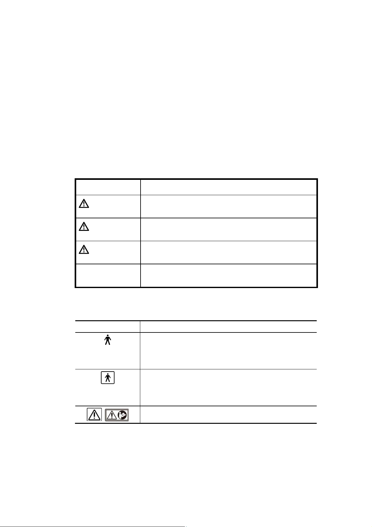
2.1 Meaning of Signal Words
In this operation manual, the signal words DANGER, WARNING, and
CAUTION are used regarding safety and other important instructions. The signal
words and their meanings are defined as follows. Please understand their meanings
clearly before reading this manual.
Signal word Meaning
DANGER
WARNING
CAUTION
CAUTION Indicates a potentially hazardous situation which, if not
Indicates an imminently hazardous situation which, if not
avoided, will result in death or serious injury.
Indicates a potentially hazardous situation which, if not
avoided, could result in death or serious injury.
Indicates a potentially hazardous situation which, if not
avoided, may result in minor or moderate injury.
avoided, may result in property damage.
2.2 Meaning of Safety Symbols
Symbol Description
Type-B applied part
* Type B when Type-B applied parts are connected.
The heart sound sensor and pulse wave sensor that can
be connected to this system are Type-B applied parts.
Type-BF applied part
* Type BF when Type-BF applied part is connected.
The reference signal cables that can be connected to this
system are Type-BF applied parts.
"Attention" (Refer to the operation manual.)
No. 2B771-004EN*M
2-1
Page 17

2.3 Ensuring the Safety of Patients and Operators
Observe the following safety precautions to ensure the safety of patients and operators.
DANGER: This system must be used only when the potential benefits to
the patient are judged outweigh the possible risk to the
patient.
WARNING: 1. Do not use damaged or defective transducers. Doing so
may result in injury to the patient.
2. Take special precautions when examining a patient with
high temperature. A high patient temperature may slow
down cooling of the transducer surface, which may result
in a burn injury to the patient.
If the surface temperature of the transducer becomes
abnormally high, stop using the transducer and contact
your TOSHIBA service representative.
3. This device is contraindicated for ophthalmic use or any
application that causes the acoustic beam to pass
through the eye.
4. Do not look inside the DVD/CD unit. The emitted laser
beam is hazardous to the eyes and other parts of the
body.
5. Prolonged and repeated use of keyboards can result in
hand or arm nerve disorders in some individuals.
Observe the local institutional work safety/health
regulations on keyboard use.
6. Do not use the Fusion function (option) for patients who
use electronic life-support devices (for example, a cardiac
pacemaker or defibrillator). The magnetic field generated
in Fusion mode may affect such devices.
CAUTION: 1. Do not use the transducer on the same region of the patient
for a prolonged period. Low temperature burns may occur.
Use the transducer for the minimum period of time that is
required for diagnosis. Though the transducer surface
temperature may exceed the patient's body temperature
under some ambient conditions and usage modes, the use
of the transducer for normal ultrasound diagnosis is unlikely
to cause low temperature burns.
2. Do not sit on the system. Doing so may result in the system
moving unexpectedly, causing you to lose your balance and
fall.
3. When this system is used to examine an elderly patient or an
infant, an attendant should be present if required.
No. 2B771-004EN*M
2-2
Page 18

2.4 Preventing Electric Shocks, Fires, and Power Supply Interruptions
Observe the following safety precautions to prevent electric shocks, fires, and power
supply interruptions.
DANGER: Never use flammable or explosive gases near this system.
Also do not use the system with oxygen or in an oxygenenriched atmosphere. Doing so may result in an explosion
(the system is not explosion-proof).
WARNING: 1. Follow the instructions below regarding the power cable
and plug.
Insert the power plug only into a 3-pin (with protective
grounding) medical electrical outlet.
Do not connect the power cable to a 2-pin outlet using
an adapter.
Do not forcibly bend the cable.
Do not modify the power cable or plug.
Do not damage the power cable or plug.
Do not twist the power cable or plug.
Do not bundle the power cable or plug.
Do not place heavy objects on the power cable or plug.
Do not pinch the power cable or plug.
Do not subject the power cable or plug to impact.
Do not pull the power cable to disconnect the plug
from the outlet.
2. If any abnormalities (such as damage or wear) are found
on the power cable or plug, the power cable and plug
must be replaced. Stop using it immediately and contact
your Toshiba service representative. Continuing to use
the system may result in electric shock, fire, or
interruption of power supply.
3. Do not use the system if the connection to the outlet is
loose.
4. If an abnormal smell or noise, or smoke occurs,
immediately turn the main power switch on the power
panel OFF and disconnect the plug from the power outlet.
Continuing to use the system with such an abnormality
may result in a fire etc. When using the system, ensure
that there is enough space for access to the main power
switch.
5. Do not allow this system or other equipment to come into
contact with the patient. If this system or other
equipment is defective, the patient may receive an electric
shock.
No. 2B771-004EN*M
2-3
Page 19
WARNING: 6. Do not connect any devices other than those specified by
TOSHIBA to the USB connector or other connectors on
the system.
7. Do not connect to the system transducers other than
those specified by TOSHIBA, to prevent accidents such
as fire.
8. Do not use a defective transducer.
9. Do not remove the covers or panels of the system. Doing
so exposes high-voltage parts.
10. When in the patient environment, the operator must not
touch any exposed connectors. In addition, if the system
covers have been removed for some reason, the operator
must be extremely careful not to touch any part where the
voltage exceeds 25 VAC or 60 VDC and the patient at the
same time. Doing so may result in an electric shock.
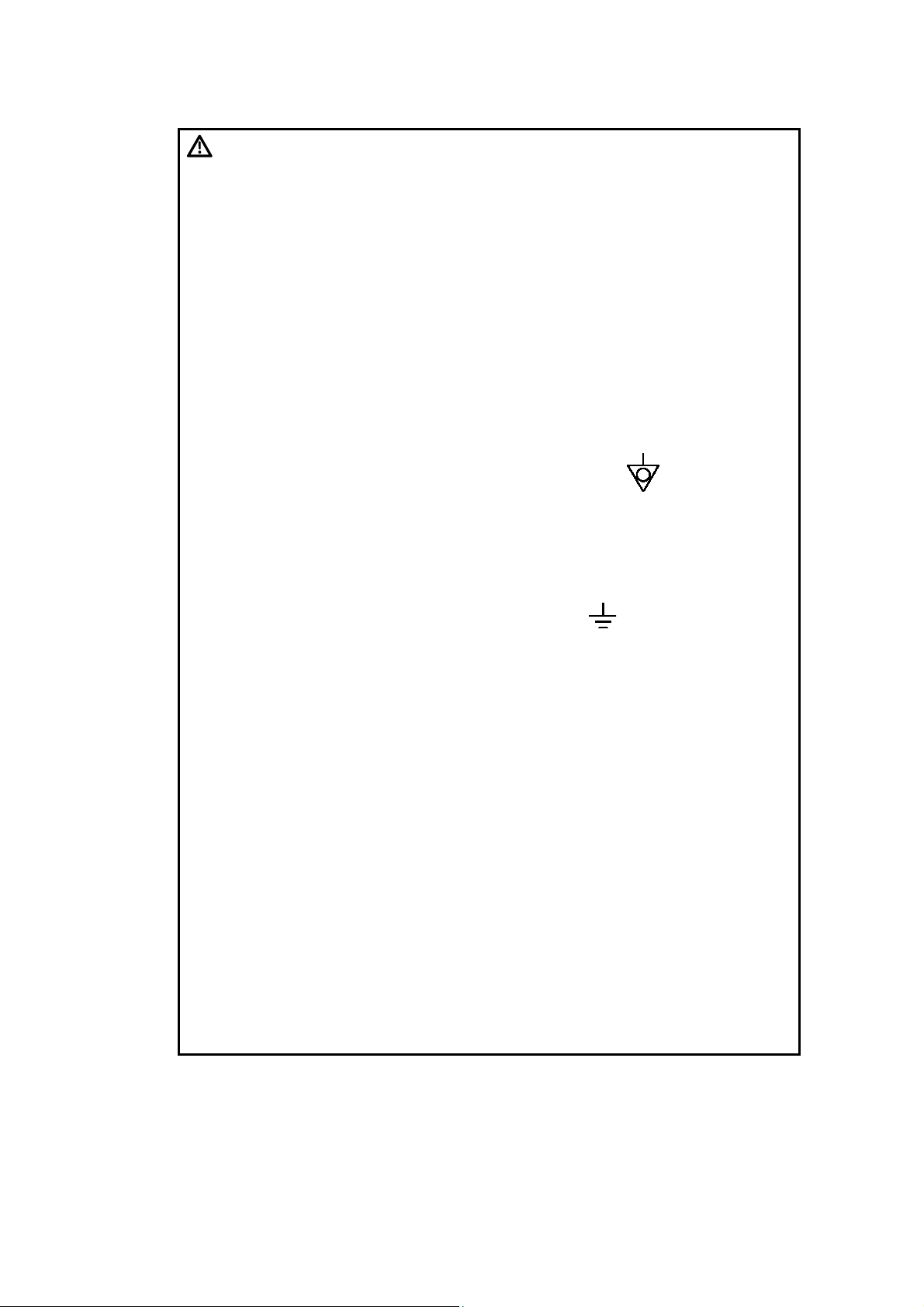
11. Connect the equipotential terminal ( ) of this system to
the equipotential bus of the facility using an equipotential
conductor. When this system is used close to a device
that is applied directly to the patient heart (such as in a
cardiac catheterization room, CCU, or ICU), voltage
equalization with the device is required to prevent an
electric shock to the patient.
12. A functional ground terminal ( ) is used to connect a
functional grounding wire between systems or between
the system and the ground for functional purposes of the
system (for example, to eliminate potential differences in
the signal level between systems or to eliminate potential
differences between the system and the ground). Do not
use the functional ground terminal for protective
grounding. Also, do not connect the functional ground
terminal to a gas pipe or water pipe. Doing so may result
in the failure of functional grounding or in a gas
explosion.
13. Use a separate socket with an appropriate rated capacity
for the supply of power to this system.
14. Do not connect this system to an outlet that shares a
circuit breaker (or fuse) with an outlet to which a device
such as a life-support system is connected. If this
system malfunctions and generates an overcurrent, or if
there is a current surge when the power is turned ON, the
circuit breaker may trip (or the fuse may blow).
15. Do not connect the diagnostic ultrasound system to the
same power outlet as another device. Doing so may
cause the circuit breaker of the facility to trip, fuses to
blow, or a fire or electric shock to occur.
No. 2B771-004EN*M
2-4
Page 20
WARNING: 16. Remove the ECG electrodes from the patient before using
devices such as electric scalpels, high-frequency therapy
equipment, electrostimulators, or electric defibrillators.
In addition, when using such devices, do not let
ultrasound transducers, PCG microphones, or pulse wave
sensors to come into contact with the patient. Doing so
may result in the patient receiving a burn injury or an
electric shock.
CAUTION: 1. To prevent electric shock, do not connect peripheral units
(such as a video printer or video recording unit) to an
external outlet. Peripheral units should be connected inside
the system. For the connection procedures, contact your
TOSHIBA service representative.
2. If any abnormality of the system is found as a result of
inspection, stop using the system and contact your
TOSHIBA service representative for repair.
3. Do not spill or spray liquids such as water onto the system
or peripheral units.
2.5 Chemical Hazard
Observe the following instruction in order to protect patients and operators from
inflammation or poisoning by chemical substances.
WARNING: Handling the cord on this product will expose you to lead, a
chemical known to the State of California to cause birth
defects or other reproductive harm.
Wash hands after handling.
2.6 Electromagnetic Compatibility (EMC)
Definition: Electromagnetic compatibility (EMC) refers to the ability to function without
causing electromagnetic interference (EMI) in other devices or systems, as
well as to a certain level of immunity to EMI from other devices or systems.
Observe the following precautions to ensure EMC.
WARNING: The use of transducers and cables other than those
specified, with the exception of transducers and cables sold
by Toshiba Medical Systems Corporation as replacement
parts, may result in increased emissions or reduced system
performance.
No. 2B771-004EN*M
2-5
Page 21

CAUTION: Malfunctions due to radio waves
(1) This system may malfunction due to electromagnetic
influence from electric scalpels, high-frequency therapy
equipment, or other devices that generate high
frequencies.
(2) The use of radio-wave-emitting devices near this unit may
interfere with its operation. Devices that generate radio
waves, such as cellular phones, transceivers, and radiocontrolled toys, must not be brought into the room where
this unit is installed and must never be used near the unit.
(3) If a device that generates radio waves is brought into the
room where this unit is installed, instruct the user to turn
OFF the power of the device immediately. This is
necessary to ensure proper operation of the system.
CAUTION: 1. Do not use this system in locations exposed to strong electric or
magnetic fields (near transformers, for example). Such fields may
adversely affect the monitor.
2. Do not use this system near devices that generate high frequencies
(such as medical telemeters and cordless telephones). Doing so may
cause the system to malfunction or to adversely affect such devices.
3. Do not use devices that generate high frequencies near other devices
or stack such devices on each other. If doing so is unavoidable,
confirm that the system operates normally at its usual operating
location.
2.7 Acoustic Power
Observe the following safety precautions.
CAUTION: 1. When a fetus is to be exposed to ultrasound, set the
acoustic power to as low a level as possible.
2. The FDA allows ultrasound equipment to output acoustic
power level TRACK3, which is higher than TRACK1,
provided that MI/TI values are displayed on the system.
This means that users now have a higher degree of
responsibility for safety. Users are thus required to
understand the bioeffects of ultrasound and their causes,
and to only then increase diagnostic capabilities by
increasing MI/TI.
Refer to section 24 "Using MI/TI" for details.
No. 2B771-004EN*M
2-6
Page 22

2.8 Preventing System Malfunctions
Observe the following precautions to prevent system malfunctions.
CAUTION: 1. Only software authorized by TOSHIBA should be installed in
this system. Otherwise, a system failure or malfunction may
result.
2. If the system is infected with malware (malicious software,
such as a computer virus or worm), data stored in the
system may be deleted, altered, or disclosed or the system
may malfunction or infect other systems. The user must
establish security measures to prevent the system from
being infected.
(a) Do not connect this system to a network for which any
of the conditions below is true:
Security control is not established for the network.
There is a risk of malware invasion in the network.
A system for which any of the following conditions is
true is connected to or can be connected to the
network:
<1> The security of the system is not controlled by
the user.
<2> The system can be accessed by persons not
authorized by the user.
<3> The system is capable of wireless
communication.
(b) The following instructions must be observed in order to
prevent this system from being infected with malware:
Do not connect this system to the Internet.
When external storage media (such as a CD or USB
flash drive) is to be used, confirm in advance that the
media is not infected with malware.
Do not perform any other actions that may result in
infection.
No. 2B771-004EN*M
2-7
Page 23
CAUTION: 1. To prevent damage to the system, do not install it in a location where
it may be exposed to the following:
Direct sunlight
Sudden temperature fluctuations
Excessive dust
Excessive shock or vibration
High temperatures
High humidity
Poor air circulation because the system air filter is blocked by a wall
etc. (A space at least 10 cm wide and 20 cm deep is required.)
2. Do not disconnect the power plug while the system is starting up.
Doing so may cause the system to malfunction.
3. If either of the following phenomena occurs, press and hold down
for 5 seconds or more to turn OFF the power of the system.
The startup screen is not displayed after waiting for 30 seconds.
The patient registration screen is not displayed after waiting for
10 minutes.
If the power is not turned ON after holding down for 5 seconds
or more, turn OFF the main power on the power panel.
Do not turn OFF the power in this manner during normal operation.
Doing so may cause the system to malfunction.
4. Do not press or use force on the main panel. Doing so may damage
the system.
5. The service outlets on the main unit provide power for recommended
external options only. Do not connect other devices to these outlets.
Doing so may result in the outlet power capacity being exceeded and
cause a system malfunction.
6. The cooling fan must be cleaned at least once a year. If the cooling
fan is clogged, the internal temperature will rise, shortening the
service life of the system. For inspection and cleaning by service
personnel, contact your TOSHIBA service representative.
7. If the main power switch on the power panel or circuit protector trips,
be sure to consult your TOSHIBA service representative. If the main
power switch is turned ON again before the problem is corrected, the
system or a connected device may sustain further damage.
No. 2B771-004EN*M
2-8
Page 24
2.9 Handling Patient and Image Data
To prevent incorrect diagnosis and reexaminations, observe the following precautions
when handling data.
CAUTION: 1. Entering patient data
Before starting an examination for a new patient, confirm
that the patient ID matches the patient to be examined. If
images are recorded with an incorrect patient ID, the data
may be mixed up with that for another patient, resulting in
incorrect diagnosis.
2. This system is provided with a lossy data compression
function for images. Although this function helps to reduce
the size of stored images, it can cause image deterioration.
The amount of compression must therefore be limited so
that the image quality is maintained at a level that does not
adversely affect image reading.
2.10 Warning Labels
Various warning labels are attached to this system in order to call the user's attention to
potential hazards.
* The symbol
use the same signal words as used in the descriptions in the operation manuals.
Read the operation manuals carefully before using the system.
The appearance and location of each warning label are as follows.
on the warning labels indicates safety precautions. Warning labels
No. 2B771-004EN*M
2-9
Page 25
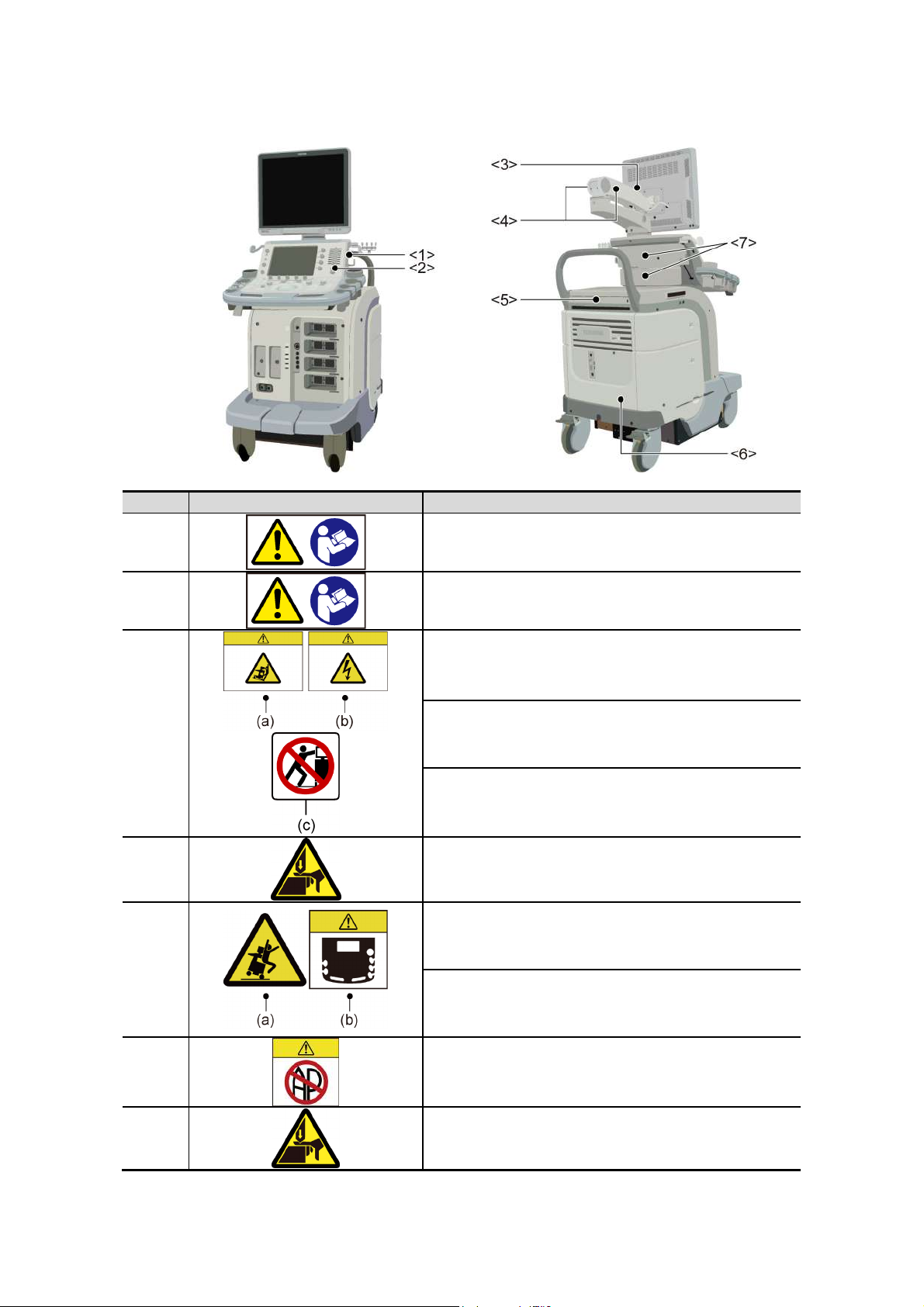
Warning labels on systems complying with the European Directive 93/42/EEC
No. Label Meaning
<1>
<2>
<3>
<4>
<5>
Urges caution related to handling of the transducers.
For handling of the transducers, refer to the
transducers' operation manual.
Cautions that the MI/TI must be controlled as low as
reasonably achievable.
(a) Cautions that the system must be placed on a
horizontal surface.
(b) Cautions that the cover must not be removed in
order to prevent electric shock.
(c) Cautions that the system must not be leaned on
nor pushed from the side.
Cautions regarding handling of the monitor arm.
(a) Cautions against sitting on the system.
<6>
<7>
(b) Urges caution related to the switches on the
main panel.
Cautions that the system must not be used around
flammable gases.
Cautions that hands may be caught when the height
of the main panel is adjusted.
No. 2B771-004EN*M
2-10
Page 26
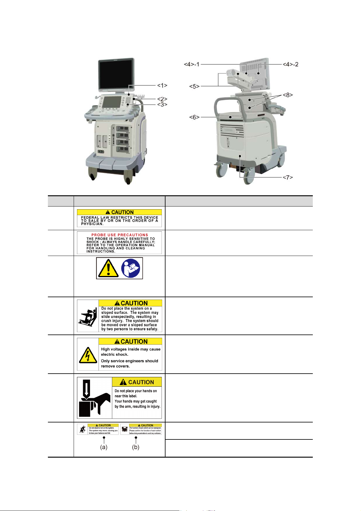
Warning labels on other systems
No. Label Meaning
<1> Cautions that restrict this device to sale by or on the
order of a physician. (USA/Canada only)
<2> Urges caution related to handling of the transducers.
<3>
<4>-1 Cautions that the system must be placed on a
<4>-2 Cautions that the cover must not be removed in
(a) Cautions that the MI/TI must be controlled as
low as reasonably achievable.
(b) As in the USA and Canada, cautions that
displayed MI/TI are mean values. Refer to
subsection 24.2.2 "MI/TI display description".
horizontal surface.
order to prevent electric shock.
<5> Cautions regarding handling of the monitor arm.
<6> (a) Cautions against sitting or leaning on the
system.
(b) Urges caution related to the switches on the
main panel.
No. 2B771-004EN*M
2-11
Page 27
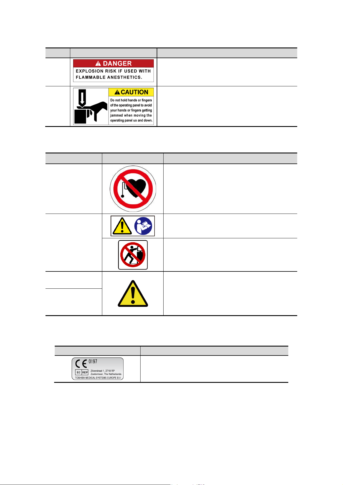
No. Label Meaning
<7> Cautions that the system must not be used around
flammable gases.
<8> Cautions that hands may be caught when the height
of the main panel is adjusted.
<<Warning labels for options>>
Item Label Meaning
Cautions that the Fusion function (option) must
not be used for patients who use electronic life-
Fusion unit
(UIFR-A500A)
Fusion Pole Cart
(UZWT-A500A)
support devices (for example, a cardiac
pacemaker or defibrillator). The magnetic field
generated in Fusion mode may affect such
devices.
Cautions that the operation manual must be
referred to.
Cautions that the Fusion pole cart must not be
leaned on or pushed forcefully from the side.
M-TEE hanger kit
(UAEH-770A)
Motor drive
M-TEE hanger kit
(UAEH-002A)
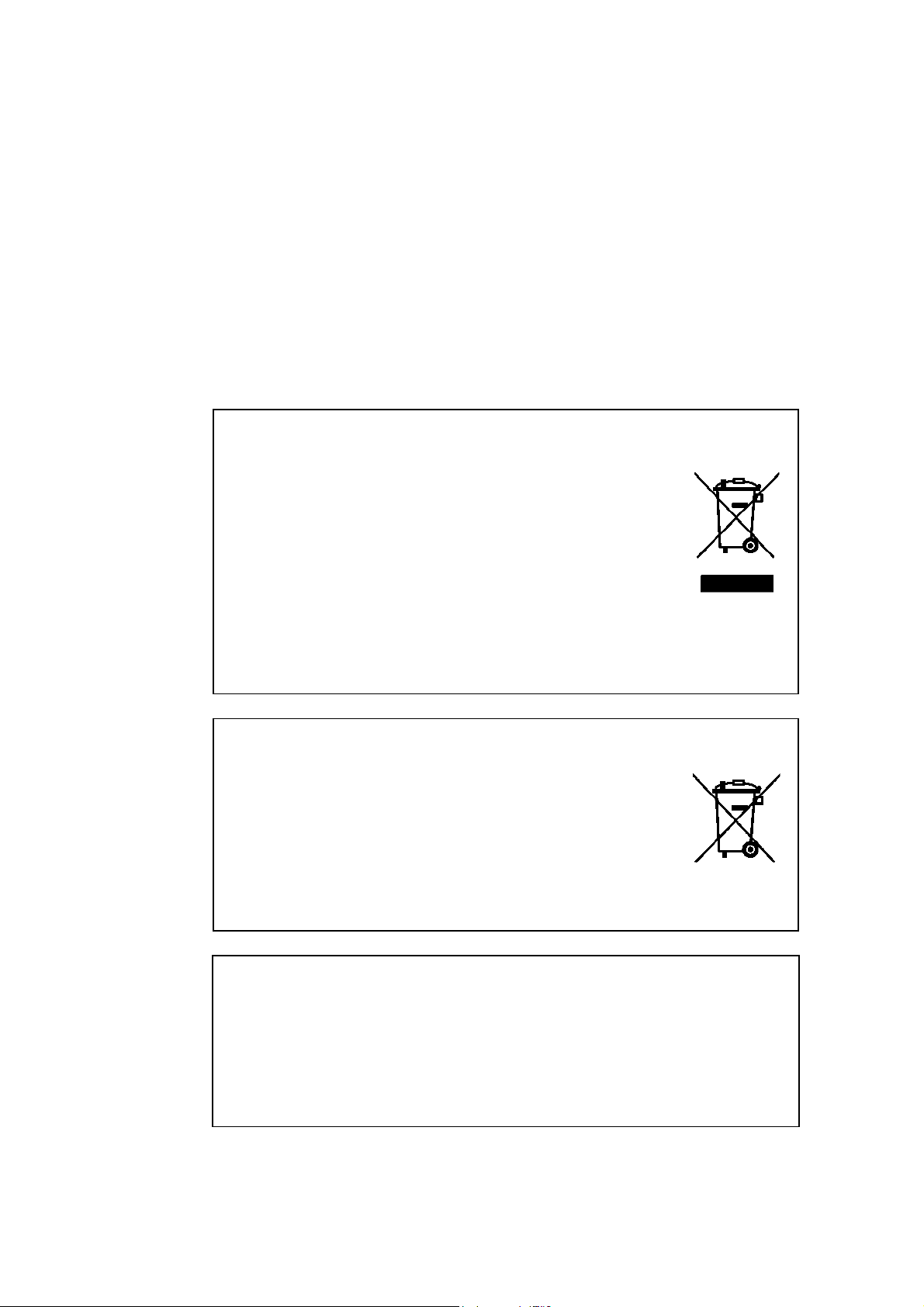
2.11 Regulatory Labels
Label Meaning
Precautions related to handling
1. Place the transducer in the box for
transportation.
This label indicates this device complies with European
Directive 93/42/EEC and subsequent amendments.
2. Do not allow the transducer to bump against
the main unit.
No. 2B771-004EN*M
2-12
Page 28

2.12 Precautions Concerning Clinical Examination Techniques
(1) This operation manual is intended for users who are well-versed in the principles
and basic techniques of ultrasound.
(2) This system must be used only by medical personnel fully trained in clinical
examination techniques.
(3) This operation manual does not describe clinical examination techniques.
Selection of the proper clinical examination technique must be based on
specialized training and clinical experience.
No. 2B771-004EN*M
2-13
*
Page 29

3. General Information on Usage and Maintenance
1. The responsibility for maintenance and management of the product after delivery
resides with the customer who has purchased the product.
2. The warranty does not cover the following items, even during the warranty period:
(1) Damage or loss due to misuse or abuse.
(2) Damage or loss caused by Acts of God such as fires, earthquakes, floods,
lightning, etc.
(3) Damage or loss caused by failure to meet the specified conditions for this
system, such as inadequate power supply, improper installation, or
unacceptable environmental conditions.
(4) Damage or loss due to mobile use in a vehicle which is not authorized by
TOSHIBA.
(5) Damage or loss due to use outside the territory in which the system was
originally sold.
(6) Damage or loss involving system purchased from a source other than
TOSHIBA or its authorized distributors or agents.
3. This system shall not be used by persons other than fully qualified and certified
medical personnel.
4. Do not make changes or modifications to the software or hardware of this product.
5. In no event shall TOSHIBA be liable for problems, damage, or loss caused by
relocation, modification, or repair performed by personnel other than those
designated by TOSHIBA.
6. The purpose of this system is to provide physicians with data for clinical diagnosis.
The responsibility for diagnostic procedures lies with the physicians involved.
TOSHIBA shall not be liable for the results of diagnostic procedures.
7. Important data must be backed up on external recording media such as clinical
records, notebooks, floppy disks, or magnetic tapes.
8. TOSHIBA shall not be liable for loss of data stored in the memory of this system
caused by operator error or accidents.
9. This manual contains warnings regarding foreseeable potential dangers. Be alert
at all times to dangers other than those indicated.
10. TOSHIBA shall not be liable for damage or loss that results from negligence or
from ignoring the precautions and operating instructions contained in this operation
manual.
11. Ultrasound transducers are precision equipment and should be handled with
proper care. If they are not handled according to the instructions in the operation
manual, problems such as scratches, holes, defects in the acoustic lens surface,
twisting of the transducer cable, or degradation of the ultrasound images may
result.
Note that the warranty does not cover problems caused by improper handling of
the transducers.
No. 2B771-004EN*M
3-1
Page 30
12. TOSHIBA shall not be liable for any error or malfunction that results from use of a
transducer other than that specified by TOSHIBA.
13. On the occasion of change of the administrator or manager for this system, be sure
to hand over this operation manual.
14. When this system is to be transported, be sure to contact your TOSHIBA service
representative first. Special packaging must be performed by a TOSHIBA service
engineer or a service engineer authorized by TOSHIBA. TOSHIBA does not
assume any responsibility for damage resulting from transportation of this system
without consulting TOSHIBA.
15. When disposing of this system, contact your TOSHIBA service representative. Do
not dispose of this system without consulting TOSHIBA service representative first.
TOSHIBA does not assume any responsibility for damage resulting from disposal
of this system without consulting TOSHIBA.
NOTE: Concerning the WEEE label
The following information is only for EU member states:
The use of this symbol indicates that this product
should not be treated as household waste.
By ensuring that this product is disposed of correctly,
you will help prevent potential negative consequences
for the environment and human health, which could
otherwise be caused by inappropriate waste-handling
of this product.
For more detailed information concerning the return
and recycling of this product, please consult the
supplier from whom you purchased the product.
* For system products, this label may be attached to the main unit only.
NOTE: Concerning BATTERIES
The following information is only for EEA countries:
The directive 2006/66/EC requires separate collection
and appropriate disposal of spent batteries.
This product also contains batteries that are not
intended to be replaced by the user.
Replacement of those batteries will usually be done
during regular maintenance or service by service staff
who can also arrange proper disposal.
NOTE: Regulatory information
The high-efficiency LCD backlights used in this product contain 5 mg or
less of mercury, the disposal of which may be regulated due to
environmental considerations.
For disposal or recycling information, please contact your local authorities
or the Electronic Industries Alliance (www.eiae.org).
This information is only for the USA.
No. 2B771-004EN*M
3-2
Page 31

NOTE: Perchlorate Material - special handling may apply.
See http://www.dtsc.ca.gov/hazardouswaste/perchlorate/
This is applicable to California, USA, only.
16. This system shall be connected to a network only if security measures against
malware infection have been established for the network.
17. Expected service life
The expected service life is 7 years if the specified maintenance and inspection
procedures are performed.
However, the service life depends on usage conditions, and individually specified
periods, if any, take precedence.
18. This manual provides information on minimizing the environmental impact (carbon
dioxide emission, power consumption, etc.) of this system. Use the information
appropriately according to the intended use of the system.
No. 2B771-004EN*M
3-3
*
Page 32

4. Use Conditions
4.1 Power and Environmental Requirements
Item Specifications
Power Line voltage
Line frequency 50 Hz to 60 Hz
Power consumption USA 1440 VA
Operating
environmental
conditions
Storage and
transportation
conditions
Patient environment This system is designed to be used in the
Ambient temperature 10°C to 35°C
Relative humidity 35% to 80% (no condensation)
Atmospheric
pressure
Ambient temperature -10°C to 50°C
Relative humidity 30% to 80% (no condensation)
Atmospheric
pressure
USA 120 VAC 10%
Europe 220 to 240 VAC 10%
Other 1 110 to 120 VAC 10%
Other 2 220 to 240 VAC 10%
Europe 1500 VA
Other 1 1440 VA
Other 2 1500 VA
700 hPa to 1060 hPa
50% or less if the ambient temperature exceeds
40°C
700 hPa to 1060 hPa
environment specified in the figure below.
No. 2B771-004EN*M
4-1
Page 33

4.2 Environmentally Friendly Usage and Maintenance Management
Observe the following to keep environmental impact to a minimum.
(1) Turn the system power OFF when the system is not in use.
(2) When the system is not to be used for an extended period of time, turn OFF the
main power switch on the power panel and disconnect the power plug from the
outlet.
(3) Freeze the image by pressing
performed.
whenever examination is not being
No. 2B771-004EN*M
4-2
*
Page 34

5. System Configuration
5.1 Standard Configuration
(1) Main unit of the system
(2) Accessories
Operation manuals
Cables
Transducer holder
Gel holder
5.2 List of Optional Units
The following optional units are available with this system.
No. Item Model
1 CW unit UICW-A500A
2 Reference signal unit UJUR-A500A (Except for USA)
3 Reference signal unit UJUR-A501A (Only for USA)
4 Reference signal sensor unit UJUR-772A
5 Mounting kit for peripheral unit UZRI-A500A
6 Mounting kit for peripheral unit UZRI-A501A
7 Footswitch UZFS-A500A
8 Gel warmer UZGW-007A
9 M-TEE hanger kit UAEH-770A
10 Motor drive M-TEE hanger kit UAEH-002A
11 4D unit UIMV-A500A
12 Battery kit UEBT-A500A
13 HV power kit UIHV-A500A
14 Fusion unit UIFR-A500A
15 Fusion Pole Cart UZWT-A500A
16 Mounting kit for fusion sensor* UAFS-001A
17 Mounting kit for fusion sensor* UAFS-002A
18 Mounting kit for fusion sensor* UAFS-003A
19 Transducer cable hanger kit UZMK-A500A
20 CV kit UACV-A500A
*: The mounting kit for fusion sensor is used in combination with the fusion unit
UIFR-A500A.
No. 2B771-004EN*M
5-1
Page 35

5.3 Compatible Peripheral Devices
The following devices are available with this system.
No. Item Model
1 Black-and-white digital printer UP-D897 (SONY)
P95DW (MITSUBISHI)
2 Color digital printer CP30DW (MITSUBISHI)
UP-D25MD (SONY)
3 DVD video recorder DVO-1000MD (NTSC/PAL: SONY)
BD-X201M (NTSC/PAL: JVC, for regions
other than Europe)
BD-X201ME (PAL: JVC, for Europe)
* It may not be possible to use some of the peripheral devices listed above depending
on the power conditions of the country. For details, contact your TOSHIBA service
representative.
5.4 External Storage Devices
USB flash drives and barcode readers can be connected to this system. Contact your
TOSHIBA service representative for the recommended models.
No. 2B771-004EN*M
5-2
Page 36

5.5 List of Optional Software
The following optional software is available with this system.
No. Item Model
1 Realtime ASQ kit* USAS-A500A, USAS-A500A/EL
2 Smart Fusion kit USFN-A500A, USFN-A500A/EL
3 Fly Thru. kit USFT-A500A, USFT-A500A/EL
4 Elastography kit USEL-A500A, USEL-A500A/EL
5 2D Wall Motion Tracking kit USWT-A500A, USWT-A500A/EL
6 MicroPureTM kit USMP-A500A, USMP-A500A/EL
7 CHI-Q kit USCQ-A500A, USCQ-A500A/EL
8 CHI kit USHI-A500A, USHI-A500A/EL
9 Panoramic View kit USPV-A500A, USPV-A500A/EL
10 4D STIC Imaging kit USST-A500A, USST-A500A/EL
11 Stress Echo kit USSE-A500A, USSE-A500A/EL
12 DICOM kit USDI-A500A, USDI-A500A/EL
13 1.5D Transducer kit USMS-A500A, USMS-A500A/EL
14 Protocol Assistant kit USPA-A500A, USPA-A500A/EL
15 Parametric MFI kit* USPM-A500A, USPM-A500A/EL
16 Vascularity Index kit USVI-A500A, USVI-A500A/EL
17 FLR kit* USFL-A500A, USFL-A500A/EL
18 Elastography-FLR kit* USEL-A501A, USEL-A501A/EL
19 FLEX-M kit USXM-A500A, USXM-A500A/EL
20 Luminance kit USLM-A500A, USLM-A500A/EL
21 Superb Micro vascular Imaging kit USMI-A500A, USMI-A500A/EL
*: This option is not available in the USA.
NOTE: "/EL" is a supplemental model name indicating options supplied by electronic
license.
No. 2B771-004EN*M
5-3
Page 37

5.6 List of Available Transducers
The following transducers are available with this system.
Transducer name Principal use
PST-25BT Cardiac, pediatric, abdominal, adult cephalic, neonatal cephalic
PST-30BT Cardiac, abdominal, adult cephalic, neonatal cephalic
PST-50BT Cardiac, pediatric, and neonatal cephalic
PST-65AT Cardiac, neonatal cephalic, pediatric
PVT-350BTP*2 Abdominal
PVT-375BT Abdominal, fetal, pediatric
PVT-375MV Abdominal, fetal, pediatric
PVT-382BT Abdominal, fetal, pediatric
PVT-382MV Abdominal, fetal, pediatric
PVT-661VT Transrectal, transvaginal
PVT-674BT Abdominal, fetal
PVT-675MV Fetal
PVT-681MV Transvaginal, transrectal
PVT-712BT Neonatal cephalic, abdominal
PVT-745BTF Abdominal, small organs, intraoperative
PVT-745BTH Abdominal, small organs, intraoperative
PVT-745BTV Abdominal, small organs, intraoperative
PVT-770RT Transrectal
PVT-781VT Transrectal, transvaginal
PLT-308P*2 Abdominal
PLT-604AT Peripheral vascular, small organ, musculoskeletal
PLT-704AT Peripheral vascular, small organ, musculoskeletal
PLT-704SBT Small organs, peripheral vascular, musculoskeletal
PLT-705BTF Abdominal
PLT-705BTH Abdominal
PLT-805AT Peripheral vascular, small organs, musculoskeletal
PLT-1005BT Peripheral vascular, small organs, musculoskeletal
PLT-1202S Peripheral vascular, small organs, musculoskeletal, intraoperative
PLT-1204BT Peripheral vascular, small organs, musculoskeletal
PLT-1204BX*1 Peripheral vascular, small organs, musculoskeletal
PLT-1204MV Small organs, peripheral vascular, musculoskeletal
PET-508MA Cardiac (transesophageal)
PET-510MA*3 Cardiac (transesophageal)
PET-510MB*4 Cardiac (transesophageal)
PET-511BTM*2 Cardiac (transesophageal)
PET-512MA*2 Cardiac (transesophageal)
PET-512MC Cardiac (transesophageal)
PC-20M Cardiac, pediatric
PC-50M Cardiac, peripheral vascular, pediatric
*1: When this transducer is used, optional unit UIHV-A500A and optional software
USMS-A500A are required.
*2: This transducer is not available in the USA and Canada.
*3: This transducer is not available in the USA.
*4: This transducer is available in the USA only.
No. 2B771-004EN*M
5-4
Page 38

Transducer
name
PST-25BT
PST-30BT
PST-50BT
PST-65AT
PVT-350BTP
PVT-375BT
PVT-375MV
PVT-382BT
No. 2B771-004EN*M
PVT-382MV
PVT-661VT
PVT-674BT
5-5
PVT-675MV
PVT-681MV
PVT-712BT
PVT-745BTF
PVT-745BTH
PVT-745BTV
PVT-770RT
PVT-781VT
PLT-308P
PLT-604AT
PLT-704AT
PLT-704SBT
PLT-705BTF
PLT-705BTH
PLT-805AT
PLT-1005BT
PLT-1202S
PLT-1204BT
2D mode
M
Fund.
Pulse
Subtract
ON
Pulse
Subtract
OFF
mode
*2
*2
*2
*2
*2
*2
*2
*2
*2
*2
*2
*2
*2
*2
CDI
mode
Power
mode
/
/
/
/
Dynamic
*1
*1
*1
*1
*2
*2
*2
*2
*2
*2
Flow
mode
/
/
/
/
SMI*4
mode
*1
*1
*1
*1
Elasto-
TDI
graphy
mode
mode
*4
*2
PW
mode
CW
mode
CHI mode*4
*4
Precision
imaging
/TE
*5
*5
*5
*5
ASQ*4
Apli-
2D
Dynamic
Flow
MFI VRI
Pure
*3
*3
*3 *3
*3
*3
*3
*3 *3
*3
*3 *3
*3
*3 *3
*3
*3 *3
*3
*3
*3
*3
*3
*3
*3
*3
*3
*3
*3
*3
*3
*3 *3
*3
*3
*3
*3
*3
*3
*3
*3 *3
*3
*3
*3
*3
*3
*3
MicroPure
*3
*3
*3
*3
: Available : Not available
Page 39

Transducer
name
PLT-1204BX
PLT-1204MV
PET-508MA
PET-510MA/
MB
PET511BTM
PET-512MA
No. 2B771-004EN*M
PET-512MC
PC-20M
5-6
PC-50M
Transducer name
PVT-375MV
PVT-382MV
PVT-675MV
PVT-681MV
PLT-1204MV
2D mode
M
CDI
Fund.
Pulse
Subtract
ON
Pulse
Subtract
OFF
*2
*2
mode
Power
mode
Dynamic
mode
Flow
mode
SMI*4
mode
Elasto-
TDI
graphy
mode
mode
*4
PW
mode
CW
mode
2D
*3
CHI mode*4
Dynamic
Flow
MFI VRI
*3
ApliPure
MicroPure
*4
Precision
imaging
/TE
*5
*5
*5
*5
*5
ASQ*4
: Available : Not available
4D Live mode*4 Single Sweep mode*4
Fund.
Pulse
Subtract
ON
Pulse
Subtract
Fund.
OFF
Pulse
Subtract
ON
Pulse
4D CHI
Subtract
OFF
*2 *3
*2 *3
*2
*2 *3
*2 *3
*4
STIC*4
*1
/
STIC
color*4
/ *1
/ *1 / *1
Volume
color*4
4D
Biopsy*4
FlyThru*4
: Available : Not available
*1) Depends on the preset. *2) Differential THI *3) Not available in the USA. *4) Optional software is required. *5) TE
*
Page 40

6. Names and Functions of Each Section
6.1 Name of Each Section
Systems with the main power switch on the rear
No. 2B771-004EN*M
6-1
Page 41

Systems with the main power switch on the side
No. 2B771-004EN*M
6-2
Page 42

6.2 Main Panel
The default switch layout is shown in the figure below:
The functions assigned to the switches can be changed. Therefore, the actual switch
settings of the system may differ from the default settings described in this manual.
Confirm the Output, Store, Freeze, and other important settings before using the
system.
It is also possible to change the positions of switches related to measurements,
modes, or printer output (user function switches). To change the settings, contact
your TOSHIBA service representative.
CAUTION: Do not press several switches at the same time. Doing so may cause a
malfunction.
No. 2B771-004EN*M
6-3
Page 43

No. Switch name Function
<1>
<2>
<3>
<4>
<5>
<6> Touch panel
<7>
Turns the power ON/OFF.
Lights when the main power switch on the power panel is ON.
Goes out when the system is started up.
Lights again when the system is shut down.
Indicates the battery charge level.
(Lights when the main power switch on the power panel is ON.)
Lights green if the batteries are adequately charged.
Lights orange if the batteries need to be charged.
Displays the [Patient Registration] screen.
The ID and measurement data for the previous patient are
deleted and the initial conditions are restored.
Used to select the transducer.
Displays switches specific to the type of examination (switches for
image control, measurements, etc.). The desired switch can be
touched with a finger to operate it.
The functions of these knobs vary depending on the mode or
other conditions.
The functions currently assigned to the knobs are displayed on
the touch panel.
<8>
<9>
<10>
<11>
<12>
<13>
<14>
<15>
Used to specify the echo reception sensitivity for various depths
calculated from the body surface.
Used to set the acoustic power.
Returns the settings of scan range, Color ROI, and sampling gate
to their initial values.
Displays monochrome and color images simultaneously in real
time.
Starts trapezoid scanning.
Enables text annotations to be added to images.
Starts the [Worksheet] screen.
Starts the [Exam Review] screen.
No. 2B771-004EN*M
6-4
Page 44

No. Switch Function
<16>
<17>
<18>
<19>
<20>
<21>
<22>
<23>
Starts up the [Patient Browser] screen.
Displays the previously acquired images or other data.
Starts basic measurement mode.
Starts basic measurement mode.
Starts application measurement mode.
The function of this knob varies according to the mode.
Measurement modes : Used to edit measurement results (for
example, modification of an ellipse or a
trace).
Body mark entry mode : Rotates the transducer mark on the
body mark.
Annotation mode : Rotates the arrow mark.
Switches to M mode.
The dial around the knob is used to adjust the gain in M mode.
Switches to CW mode.
Switches to PW mode.
The dial around the knob is used to adjust the gain in Doppler
mode.
<24>
<25>
<26>
<27>
<28>
Switches to POWER mode.
Switches to CDI mode.
The dial around the knob is used to adjust the gain in Color mode.
TM
Switches to Dynamic Flow
mode.
Switches to 2D display mode.
The dial around the knob is used to adjust the gain in 2D mode.
Trackball : Used to move the cursor and measurement
markers.
Palm Dial :
During real-time display : Used to specify the gain in 2D mode.
In Freeze mode : Used to play back a loop in Cine
review mode and to adjust the
playback speed.
Used to edit measurement results in
measurement modes.
Rotates the transducer mark on the
body mark in Body mark entry mode.
Rotates the arrow mark in Annotation
mode.
No. 2B771-004EN*M
6-5
Page 45

No. Switch Function
<29>
<30>
<31>
<32>
<33>
<34>
(Wheel)
Used to insert a body mark.
Turns display of the cursor ON/OFF.
Used to manipulate thumbnails.
Used to switch trackball functions or specify the cursor position.
Pressing (in Freeze mode) : Returns to Cine mode (when Cine
mode has been stopped due to a
measurement operation, insertion of
a body mark, insertion of an
annotation, or a similar operation).
Rotation : Feeds frames in Cine mode.
Switches the displayed image in
Exam Review mode.
Used to switch trackball functions or specify the cursor
movement.
Displays 2D mode and M or Doppler mode images at the same
time.
Freezes/unfreezes the 2D mode image.
<35>
<36>
<37>
<38>
<39>
<40>
<41>
<42>
<43>
Used for automatic adjustment of the image quality.
(Refer to
panel")
Used to specify the depth and the zoom level.
Press to switch between depth and zoom modes.
Used to change the layout format.
Switches to the dual screen.
Each time this switch is pressed, the real-time display is switched
between the right and left images.
Switches to the single screen.
Freezes the screen.
Saves short dynamic image clips.
Saves still images.
Outputs data to the specified recording device. Monochrome
printer is set as the default.
of subsection 14.1.2. "Adjustment using the main
No. 2B771-004EN*M
6-6
Page 46

6.3 Rear Panel
CAUTION: 1. Do not connect any devices other than those specified by
2. Do not connect any device that is not compliant with the
CAUTION: 1. Connect or disconnect the Ethernet cable only when the power is OFF.
If the cable is connected or disconnected while the power is ON, the
system may malfunction.
2. If a hub is being used, turn ON the power of the hub before turning ON
the power of the system. Otherwise, it may not be possible to establish
connection with the network.
TOSHIBA to the USB connector or other connectors on the
system.
required safety standards to the Ethernet port. Doing so
might cause smoke generation or electric shock.
No. Name Function
<1> S output terminal Output terminal for external imaging device
<2> Color composite terminal Output terminal for external imaging device
<3> External monitor DVI-I output Output terminal for external digital imaging
device
<4> Ethernet port Port for connection to a network for the transfer
of digital images via the network
<5> USB connector Connector for connection of a USB device
<6> USB connector Connector for connection of a USB device
NOTE: The video recording unit and the printer must be connected connectors inside
the system. Before connecting cables, contact your TOSHIBA service
representative.
No. 2B771-004EN*M
6-7
Page 47

6.4 Symbols
The following symbols are used on this system. Note that the safety symbols are not
shown here; they are shown in section 2 "General Safety Information".
Symbol Description
Functional ground
Equipotential
Main power switch OFF (AC power not supplied to
system)
Main power switch ON (AC power supplied to
system)
Power OFF (power not supplied to electronic
circuits)
Power ON (power supplied to electronic circuits)
Transducer connector A
Transducer connector B
Transducer connector C
Transducer connector D
Pencil transducer connector
ECG (Electrocardiogram)
ECG (Electrocardiogram)
PCG (Phonocardiogram)
PULSE
External input terminal
Footswitch
Alternating current (AC)
Manufacturer
Date of manufacture
Serial number
Authorized representative in the EC (on systems
complying with European Directive 93/42/EEC)
No. 2B771-004EN*M
6-8
*
Page 48

7. Preparation for Examination
7.1 Moving and Installing the System
WARNING: 1. Use the system only on a level floor. Do not place the
system at a location where the slope is 5° or more. Doing
so may result in the system falling over and causing an
injury.
2. Do not push the system from the side. If the system is
pushed from the side, it may fall down and cause injury.
3. When the system is moved over a sloped surface, it must
be moved slowly by two persons. Otherwise, the system
may slide unexpectedly and cause a serious injury.
4. When the system is moved over a step, be careful not to
allow the system to fall. When holding the system at the
bottom to help move it over a step, take special care to
prevent hand injuries.
CAUTION: 1. Lock the casters once the system is moved to its installation
location. Otherwise, the system may move unexpectedly,
injuring the patient or the operator.
2. Before moving the system, lock all movable sections, such
as the LCD monitor main panel. Otherwise, parts may move
unexpectedly, causing injury.
3. Before moving the system, confirm that all peripheral
devices are secured. If a peripheral device is not secured, it
may fall, causing injury or damage.
4. When a reference signal cable is used, disconnect it before
moving the system. Otherwise, the cable might catch the
feet or the casters, causing injury or damage.
CAUTION: 1. To prevent system malfunction, be sure to perform the following
operations before moving the system.
(a) Turn OFF the power and also turn OFF the main power switch on
the power panel.
(b) Stow the transducer in the transducer holder and hang the cables
on the transducer cable hanger.
(c) Move the system using the handle. Do not attempt to move the
system by pushing the panel or any part other than the handle.
2. Except in emergencies, do not attempt to stop system movement by
engaging the caster locks. Doing so may damage the casters.
No. 2B771-004EN*M
7-1
Page 49

(1) Before moving the system, be sure to release the caster locks.
(a) Releasing all of the locks
(b) Locking the caster for forward motion
No. 2B771-004EN*M
7-2
Page 50

(2) Move the system to its installation position using the handle.
(3) Lock the casters.
No. 2B771-004EN*M
7-3
Page 51

7.2 Handling and Connecting/Disconnecting the Transducer
7.2.1 Handling the transducer
CAUTION: 1. Do not subject the acoustic lens surface of the transducer to shock by
hitting it against a hard object or dropping it on the floor. A failure
affecting the safety or functionality of the transducer may result.
2. Do not apply stress to the transducer cable (tension, twisting, bending,
pinching, etc.). The shield wire or signal wire inside the cable may
break or short-circuit, which could result in electric shock to the patient
or operator, or abnormal ultrasound images.
3. Do not scratch or rub the acoustic lens surface of the transducer. This
may cause the transducer to fail.
For other precautions concerning handling of the transducer, read all instructions
provided in this operation manual and the operation manual supplied with the
transducer.
7.2.2 Connecting/Disconnecting the transducer
CAUTION: 1. Be sure to turn OFF the power or select another transducer connector
before connecting a transducer to or disconnecting the transducer from
the currently selected transducer connector. Connecting a transducer
to or disconnecting the transducer from the currently selected
transducer connector can cause damage to the system or the
transducer.
2. Do not connect or disconnect a transducer during system startup or
shutdown. Doing so may cause a malfunction.
(1) Connect the transducer.
No. 2B771-004EN*M
7-4
Page 52

(2) Hang the transducer cable on the cable hanger or cable hook and place the
transducer in the transducer holder.
(3) Disconnect the transducer.
No. 2B771-004EN*M
7-5
Page 53

7.3 Adjusting the Main Panel
CAUTION: When lowering the main panel, do not subject the cable hanger, cable
hook, or transducer holder to any loads. Doing so may damage them.
Adjusting the height of the main panel
Hold the handle and press
the vertical adjustment lever
upward to raise or lower the
height.
When the lever is released,
the position is locked.
No. 2B771-004EN*M
7-6
Page 54

Adjusting the horizontal position of the main panel
(1) Pull the slide lever toward
you to release its lock.
(2) While pulling the slide lever,
hold the handle, move the
main panel to adjust the
position, and then release
the slide lever.
The nearest position is
locked when the lever is
released.
No. 2B771-004EN*M
7-7
Page 55

7.4 Adjusting the Monitor
CAUTION: Before moving the system, be sure to lock the movable section
of the arm. Otherwise, the arm may move unexpectedly,
resulting in an injury
7.4.1 Locking and releasing the monitor
Locking and releasing the arm
<<Locking the arm>>
Lower the arm and turn the locking knob
in the
direction.
<<Releasing the arm>>
While pressing the locking knob, turn it in
the
direction.
Locking the monitor
No. 2B771-004EN*M
7-8
Page 56

7.4.2 Adjusting the angle of the monitor
CAUTION: Do not touch the arm or the bottom of the monitor when
adjusting the angle. Doing so may result in a hand injury.
Moving the monitor vertically
Moving the monitor horizontally
No. 2B771-004EN*M
7-9
Page 57

7.4.3 Adjusting the monitor display
The brightness ( ) and the contrast ( ) can be adjusted as required using the
buttons of the monitor.
Displaying the adjustment menu
Adjusting setting for the selected function
NOTE: 1. To restore the factory default settings, press the [+] switch while holding
down the [-] switch.
2. Pressing the [-] switch while holding down [] of the Menu switches turns
the monitor display ON/OFF.
No. 2B771-004EN*M
7-10
*
Page 58

8. Checks Before and After Use
In the interests of safety, it is the user's responsibility to carry out the following checks
before and after using the system.
8.1 Checks Before Turning ON the Power
Perform the following checks before the system power is turned ON and after the
system power is turned OFF.
No. Check item Check column
1 The temperature, humidity, and atmospheric pressure should meet the
conditions of use.
2 There should be no condensation.
3 There should be no deformation, damage, or stains to the system and
peripheral units.
* If any stains are present, perform cleaning referring to subsection 20.3.1
"Cleaning the system".
4 There should not backlash or loose screws in the casters, monitor, panel,
etc.
5 Caster locks should function correctly.
6 There should be no damage to the reference signal cable and no
looseness of the connector.
7 There should be no abnormalities such as damage, wear, or bent pins on
the power cable or plug.
8 There should be no abnormalities or stains of the transducer surface, cable
sheath, or connector, such as peeling, cracks, protruding parts, or loss of
firmness of the acoustic lens.
* If any stains are present, perform cleaning, disinfection, or sterilization
referring to the operation manual provided with the transducer.
9 No clips etc. are placed on the main panel or keyboard.
10 There should be no obstacles near the movable sections and air filter of
the system.
No. 2B771-004EN*M
8-1
Page 59

8.2 Checks After Turning ON the Power
Perform the following checks after the system power is turned ON and before the
system power is turned OFF.
No. Check item Check column
1 There should be no abnormal sound, unusual smells, or overheating.
2 No error message is displayed.
3 There should be no obviously abnormal noise, discontinuous display, or
dark areas for 2D-mode images.
4 There should be no abnormality in the date and time.
* Refer to the operation manual Applications volume for the procedures
for changing the system time.
5 The acoustic lens surface of the transducer should not be unusually hot.
(Perform check by hand.)
6 Switches and knobs on the panel should function normally.
7 There should be no abnormality in the color or display position of images
output on a printer or recorded on a video recording unit.
No. 2B771-004EN*M
8-2
Page 60

NOTE: IQ Report Feature
If an error message appears or an image with unsatisfactory quality is
displayed, use the IQ Report feature to save the image and the system
information.
<<Quick Procedure>>
* If it is not possible to perform the operation above (the menu pane is not
displayed, etc), perform the following operation.
+ +
After the operation above is completed, contact your TOSHIBA service
representative.
No. 2B771-004EN*M
8-3
*
Page 61

9. Turning the Power ON/OFF
WARNING: 1. Follow the instructions below regarding the power cable
and plug.
Insert the power plug only into a 3-pin (with protective
grounding) medical electrical outlet.
Do not connect the power cable to a 2-pin outlet using
an adapter.
Do not forcibly bend the cable.
Do not modify the power cable or plug.
Do not damage the power cable or plug.
Do not twist the power cable or plug.
Do not bundle the power cable or plug.
Do not place heavy objects on the power cable or plug.
Do not pinch the power cable or plug.
Do not subject the power cable or plug to impact.
Do not pull the power cable to disconnect the plug
from the outlet.
2. Connect the equipotential terminal ( ) of this system
to the equipotential bus of the facility using an
equipotential conductor. When this system is used close
to a device that is applied directly to the patient heart
(such as in a cardiac catheterization room, CCU, or ICU),
voltage equalization with the device is required to prevent
an electric shock to the patient.
3. A functional ground terminal ( ) is used to connect a
functional grounding wire between systems or between
the system and the ground for functional purposes of the
system (for example, to eliminate potential differences in
the signal level between systems or to eliminate potential
differences between the system and the ground).
Do not use the functional ground terminal for protective
grounding. Also, do not connect the functional ground
terminal to a gas pipe or water pipe. Doing so may result
in the failure of functional grounding or in a gas
explosion.
4. Use a separate socket with an appropriate rated capacity
for the supply of power to this system.
5. Do not connect this system to an outlet that shares a
circuit breaker (or fuse) with an outlet to which a device
such as a life-support system is connected. If this
system malfunctions and generates an overcurrent, or if
there is a current surge when the power is turned ON, the
circuit breaker may trip (or the fuse may blow).
No. 2B771-004EN*M
9-1
Page 62

WARNING: 6. Do not connect the diagnostic ultrasound system to the
same power outlet as another device. Doing so may
cause the circuit breaker of the facility to trip, fuses to
blow, or a fire or electric shock to occur.
9.1 Connecting the Power Cable and the Protective Grounding
(1) Connect the power plug to an outlet for medical equipment. By doing this, the
protective ground line is connected.
(2) Turn ON the main power switch on the power panel.
The [STANDBY] LED lights.
Systems with the main power switch on the rear
No. 2B771-004EN*M
9-2
Page 63

Systems with the main power switch on the side
No. 2B771-004EN*M
9-3
Page 64

9.2 Turning ON the Power
CAUTION: 1. Do not disconnect the power plug while the system is starting up.
Doing so may cause the system to malfunction.
2. If either of the following phenomena occurs, press and hold down
for 5 seconds or more to turn OFF the power of the system.
The startup screen is not displayed after waiting for 30 seconds.
The patient registration screen is not displayed after waiting for
10 minutes.
If the power is not turned ON after holding down for 5 seconds or
more, turn OFF the main power on the power panel.
Do not turn OFF the power in this manner during normal operation.
Doing so may cause the system to malfunction.
NOTE: 1. If the power is turned ON while a USB device, such as a flash drive, is
connected to one of the five external USB connectors, the system may not
start normally. Disconnect any USB device(s) before turning the power
ON.
2. When turning ON the power, confirm that the [STANDBY] LED is lit and
then press .
3. Do not operate the operating panel switches or keyboard while the system
is starting up. The system may not start up normally.
4. After the main power has been turned OFF on the power panel, wait for at
least for 15 seconds before turning the power ON again.
If the main power switch is turned ON immediately after the power has
been turned OFF, the system may malfunction.
No. 2B771-004EN*M
9-4
Page 65

NOTE: 1. For a cold boot, the time required to display the ultrasound image is usually
approximately 3 minutes, but varies according to the system conditions.
2. If the registration screen is closed without registering any patient data, the
2D mode screen appears and the system enters Freeze mode.
3. Directly after the system power is turned ON, the fan noise is initially loud
but reduces after a short while.
No. 2B771-004EN*M
9-5
Page 66

9.3 Turning the Power OFF
CAUTION: 1. If the power cannot be turned OFF by the normal procedure, press and
hold down for at least 5 seconds. If the power is still not turned
OFF, turn OFF the main power switch on the power panel. These
methods should not be used under normal conditions. They may
damage the system.
2. Do not turn OFF the power while printing or data saving or retrieval is in
progress. Doing so may result in printing being terminated prematurely
or in data being lost. Also, if the power is turned OFF during access to
media, the media may be damaged.
3. Do not turn the system power OFF during video recording. Doing so
may damage the hard disk of the video recording device or the inserted
media.
NOTE: If the power is turned OFF while a USB device, such as a flash drive, is
connected to one of the five external USB connectors, the system may not
shut down normally. Disconnect any USB device(s) before turning the power
OFF.
No. 2B771-004EN*M
9-6
Page 67

NOTE: 1. If the system is unlikely to be used for a long period after the power is
turned OFF, turn OFF the main power switch on the power panel and then
unplug the power cable.
2. If the power cannot be turned OFF by following the normal procedures, 2D
mode images may not be displayed when the system power is turned ON
again. In this case, perform the following procedures:
Shut down the system and turn OFF the main power switch on the
power panel on the rear of the system.
Wait for at least 15 seconds, turn ON the main power switch on the
power panel, and then turn ON the power again.
3. After the main power has been turned OFF on the power panel, wait for at
least 15 seconds before turning the power ON again.
If the main power switch is turned ON immediately after the power has
been turned OFF, the system may malfunction.
4. The following message may be displayed during operation.
This message indicates that a problem has occurred with the patient data
handling functions (image storage, playback, or deletion) and that the
system has entered restricted operation mode to protect the data.
In restricted operation mode, do not use the Store, Exam Review, or
Patient Browser functions. If these functions are used, the patient data
handling functions cannot be performed. Reboot the system as soon as
the current examination is completed.
Note that the message can be cleared by clicking [Close] and scanning
can be performed normally.
No. 2B771-004EN*M
9-7
Page 68

NOTE: 5. When [Shutdown] is selected in the [Power Control] dialog during
copying of patient data, transfer of patient data, or burning of patient data
onto a CD/DVD, the following dialog is displayed.
No. Item Function
[Continue]
<1>
[After procs end]
<2>
[Save procs]
<3>
[Cancel]
<4>
The current process is terminated and the
shutdown process is started. If this is selected
during CD/DVD burning, the burn process is
canceled (the CD/DVD will be damaged) and the
shutdown process is started.
The shutdown process is started after the current
process is completed.
The current process is paused (resumed) and the
shutdown process is started. If this is selected
during CD/DVD burning, the burn process is
canceled (the CD/DVD will be damaged) and the
shutdown process is started.
The dialog is closed and the current process is
continued.
No. 2B771-004EN*M
9-8
Page 69

9.4 Standby Mode
Standby mode is a function for suspending system operation without shutting down the
system completely.
CAUTION: 1. Do not set the system to Standby mode while printing or data saving or
retrieval is in progress. Doing so may result in printing being
terminated prematurely or in data being lost. Also, if the power is
turned OFF during access to media, the media may be damaged.
2. Do not set the system to Standby mode during video recording. Doing
so may damage the hard disk of the video recording device or the
inserted media.
9.4.1 Setting Standby mode
No. 2B771-004EN*M
9-9
Page 70

NOTE: 1. A message recommending standard power OFF (shutdown) is displayed in
the following cases.
The continuous power ON time*1 has exceeded 48 hours or the
cumulative power ON time*2 has exceeded 3.5 days (84 hours).
Displayed message: [Due to the length of elapsed time since Startup,
Shutdown is recommended.]
The system has been started up from Standby mode 7 times or more
continuously.
Displayed message: [Overuse of resume. Shutdown is
recommended.]
2. In the following cases, a message is displayed and the Standby function
cannot be used. Turn the system power OFF in standard mode
(shutdown).
The continuous power ON time*1 has exceeded 96 hours or the
cumulative power ON time*2 has exceeded 5 days (120 hours).
Displayed message: [Due to the length of elapsed time since Startup,
select Shutdown or Cancel.]
The system has been started up from Standby mode 10 times or more
continuously.
Displayed message: [Overuse of resume. Select Shutdown or
Cancel.]
*1: This is the cumulative time for which the system has been used
continuously.
*2: When Standby mode is used, this is the cumulative time for which the
system power has been ON after the system power was last turned ON in
standard mode (the standby periods are not included).
3. The standby function cannot be used in the following cases. In such
cases, the message shown below is displayed. When the use of these
functions is completed or terminated, the Standby function becomes
effective again. Note that if any settings of the functions have been
changed, the system power should be turned OFF in standard mode
(shutdown).
When using a maintenance function or a preset function
Displayed message: [You can only select shutdown from
maintenance menu.]
When a USB flash drive is connected
Displayed message: [Standby is disabled while the USB flash drive is
connected.]
4. If the main power switch on the power panel is turned OFF or the system
power cable is disconnected while the system is in Standby mode, Standby
mode is canceled and the system is started up in standard power ON
mode. If the battery kit (option) is installed, Standby mode is maintained
even when the main power switch on the power panel is turned OFF during
Standby mode. If the battery level is low, however, the system is started
up in standard power ON mode when it recovers from the Standby status.
If the battery kit is installed, the battery is charged automatically while the
main power switch on the power panel is ON.
The battery is intended to maintain the memory that stores system
information required for the Standby function. The system cannot be
started up using the battery only.
Contact your TOSHIBA service representative for the battery kit.
No. 2B771-004EN*M
9-10
Page 71

NOTE: 5. Do not connect a USB device such as a flash drive to any of the external
USB connectors (the system is provided with five USB connectors) when
the system is in the Standby status. Doing so may result in the system not
starting up normally from the Standby status.
9.4.2 Recovery from the Standby status
CAUTION: 1. Do not disconnect the power plug from the outlet while the system is
resuming after being paused. The system may malfunction.
2. If either of the following phenomena occurs, press and hold down
for 5 seconds or more to turn OFF the power of the system.
The startup screen is not displayed after waiting for 30 seconds.
The patient registration screen is not displayed after waiting for
10 minutes.
If the power is not turned ON after holding down for 5 seconds or
more, turn OFF the main power on the power panel.
Do not turn OFF the power in this manner during normal operation.
Doing so may cause the system to malfunction.
NOTE: 1. When resuming the system from pause status, confirm that the
[STANDBY] LED is blinking and then press .
2. Do not operate the operation panel switches or keyboard while the system
is recovering from Standby status. The system may not start up normally.
3. Normally, the ultrasound image is displayed approximately 1 or 2 minutes
after the power switch is pressed in the standby status; however, the actual
time required varies depending on the system status.
No. 2B771-004EN*M
9-11
Page 72

NOTE: 4. Directly after the system power is turned ON, the fan noise is initially loud
but reduces after a short while.
5. Rarely, the message shown below may be displayed when an attempt is
made to start the system from the Standby status. In such cases, select
[OK] to close the message dialog. Then shut down the system and start it
up again.
Displayed message: [The system failed to start. Please restart the
system. Error code: XXX]
6. After the main power has been turned OFF on the power panel, wait for at
least 15 seconds before turning the power ON again.
If the main power switch is turned ON immediately after the power has
been turned OFF, the system may malfunction.
9.5 Preparation for Use During Surgery or for Emergency Cases
WARNING: Prepare a backup system when an urgent examination is to
be performed, for example during an operation or for an
emergency case. If a severe problem should occur with the
system, the normal operation of the system may not be
recovered by turning the power OFF/ON and the examination
may not be able to continue.
9.5.1 Preparation of a backup system
Prepare a backup system when an urgent examination is to be performed (for example,
examination during emergency surgery).
9.5.2 Power OFF/ON in the case of system failure
When any of the following abnormalities occurs in the system, recovery may be possible
by turning the system power OFF/ON.
An error message is displayed and does not disappear.
The screen display is abnormal.
System operations are disabled.
If the system is still abnormal even after power OFF/ON, use the backup system.
NOTE: When turning ON the power, confirm that the [STANDBY] LED is lit and then
press .
No. 2B771-004EN*M
9-12
*
Page 73

10. Basic Screen and Menu
10.1 Display of Various Data Items
In addition to ultrasound images, various data items are displayed on the monitor.
This section describes the screen display common to all modes. Refer to section 14
"Display and Operation in Each Mode" for the display specific to each mode.
CAUTION: The free space on the hard disk is displayed at the top of the
screen as " ". If there is less than 35 GB of free space,
the icon is highlighted in yellow. The color of the free space
indicator changes to red when the free space falls below 20 GB.
When the free space falls below 1 GB, the message [HDD is full.
Please delete some images in Patient Browser and try again.] is
displayed in the information message display area on the
screen and no more data can be stored. Delete unnecessary
data before saving new data.
* For the data deletion procedure, refer to section 2 of the
operation manual, Applications volume.
No. 2B771-004EN*M
10-1
Page 74

CAUTION: When
system is ready to output images to the printer. Confirm that printing is
completed by checking the printed images output from the printer.
Note that if the next print operation is performed while this icon is lit, the
next image is not printed. Wait until the icon goes out before performing
the next print operation.
at the bottom left of the screen lights, it indicates that the
10.2 Displaying the Acoustic Power Data
The acoustic power data transferred from the transducer is displayed in the image
display area and in the acoustic power display area.
NOTE: Whether or not the acoustic power data is displayed depends on the mode. If
the value is low, display is not performed.
No. 2B771-004EN*M
10-2
Page 75

<Except for USA and Canada>
No. Label Description Display location
<1> [AP] Acoustic power
The current transmission value (%) is displayed.
<2> [TIS] Thermal index soft tissue
Displayed as the calculated/estimated value for
temperature increase in the soft tissues.
<3> [TIB] Thermal index bone
Displayed as the calculated/estimated value for
temperature increase in the cranial bones of a fetus or
newborn child.
<4> [MI] Mechanical index
Displayed as the value related to the mechanical
effectiveness such as cavitation.
<Only for USA and Canada>
No. Label Description Display location
<1> [AP] Acoustic power
The current transmission value (%) is displayed.
<2> [TISm] Thermal index soft tissue
Displayed as the calculated/estimated mean value for
temperature increase in the soft tissues.
Acoustic power display
area
Acoustic power display
area
Image display area
Acoustic power display
area
Acoustic power display
area
<3> [TIBm] Thermal index bone
Displayed as the calculated/estimated mean value for
temperature increase in the cranial bones of a fetus or
newborn child.
<4> [MIm] Mechanical index
Displayed as the mean value related to the mechanical
effectiveness such as cavitation.
Image display area
No. 2B771-004EN*M
10-3
Page 76

10.3 Thumbnail Display
The thumbnails representing the data acquired in the current study are displayed in the
thumbnail area.
If previous study datasets for the same patient are present in the HDD, the study dates
and exam types of these datasets are displayed in the study area. When a study date
is clicked, the thumbnails representing the data for that date are displayed.
The system recognizes different studies as belonging to the same patient when all of
the following items in the studies match.
Patient ID
Patient name
Sex
If any of these items do not match and the studies are therefore not recognized as
belonging to the same patient, the patient information edit function (refer to subsection
2.2.6 of the operation manual Applications volume) of the [Patient Browser] can be
used to make the system recognize these studies as belonging to the same patient.
No. 2B771-004EN*M
10-4
*
Page 77

11. Starting an Examination
CAUTION: 1. Before starting an examination for a new patient, confirm
that the patient ID matches the patient to be examined. If
images are recorded with an incorrect patient ID, the data
may be mixed up with that for another patient, resulting in
incorrect diagnosis.
2. Enter the height and the weight correctly. Otherwise, the
BSA may be calculated incorrectly.
3. Check the date format before entering the date of birth.
Otherwise, the age may be calculated incorrectly.
NOTE: 1. Be sure to register and save the patient ID before starting an examination
for a new patient. If measurement is performed for a new patient for whom
the patient ID has not been registered or saved, the measurement results
and other data cannot be saved in the system.
2. Periodically back up the saved data (image data and exam history) to
external storage media. Data stored in the system may be deleted as a
result of an operational error or an accident (problems that occur in
personal computers can also occur in this system).
3. Delete unnecessary data regularly. If the available storage space is low,
new data may not be saved.
4. Before deleting data, confirm the date and the patient ID, patient name,
etc. to ensure that incorrect data is not deleted.
5. If patient data or exam data is to be modified, confirm that the modifications
are correct before saving them. Once the data is saved, the previous data
cannot be restored.
6. If the rows of the History data in the patient data entry screen are switched,
turn ON the system again.
7. When the patient information is registered and is then
selected, the live image is normally displayed within 10 seconds.
However, if relatively high-load processing (such as saving, loading,
copying, or conversion of a large amount of data) is performed immediately
before this, it may take approximately 30 seconds to display the live image.
If the live image is not displayed after 30 seconds, an error message is
displayed. Reboot the system.
No. 2B771-004EN*M
11-1
Page 78

11.1 Entering and Saving Data on the [Patient Registration] Screen
Start the exam by entering the patient details on the [Patient Registration] screen.
<<Exam types>>
Dropdown list item Exam type Dropdown list item Exam type
[Abdomen] Abdomen general [Neo-Head] Neonatal head
[Carotid] Carotid arteries [Neo-General] Neonatal abdomen
general
[Thyroid] Thyroid glands [Neo-Hip] Neonatal hip joints
[Breast] Breast, including
mammary glands
[OB] Obstetrics [PV-Arterial] Peripheral blood vessels
[GYN] Gynecology [Digits] Peripheral blood vessels
[Endo-Vaginal] Endovaginal [MSK] Musculoskeletal
[Fetal Heart] Fetus cardiovascular [Prostate] Prostate gland
[Adult Heart] Cardiovascular [Kidney] Kidneys
[Pediatric Heart] Pediatric cardiovascular [Testes] Testes
[Coronary] Coronary arteries [OTHER] Others
[TCD] Transcranial Doppler [M-TEE] Transesophageal
[PV-Venous] Peripheral blood vessels
(veins)
(arteries)
(fingers and toes)
No. 2B771-004EN*M
11-2
Page 79

NOTE: 1. The ID and name are displayed as "date + unique character string".
If more than one system is used at the site, be sure to set a unique
character string so that the system can be identified.
2. Do not enter a patient ID consisting of spaces only. The examination will
not start.
3. Equations for calculating BSA (body surface area)
BSA (m2) is calculated when patient height (cm) and weight (kg) are
entered on the [Patient Registration] screen.
The following expressions are available for calculating BSA.
The desired expression can be selected from a pull-down menu.
(a) Occidental
BSA = 0.007184 Height
0.725
Weight
0.425
(b) Oriental (Adult)
BSA = 0.007358 Height
0.725
Weight
0.425
(c) Oriental (12-14)
BSA = 0.010265 Height
0.651
Weight
0.423
(d) Oriental (6-11)
BSA = 0.008883 Height
0.663
Weight
0.444
(e) Oriental (1-5)
BSA = 0.038189 Height
0.362
Weight
0.423
(f) Oriental (0)
BSA = 0.009568 Height
0.655
Weight
0.473
4. It is also possible to enter the year of a date of birth using the Japanese
calendar (combination of the era name "M (Meiji)", "T (Taisho)", "S
(Showa)", or "H (Heisei)" and the year in the era). The entered year is
converted into the corresponding Western calendar year and displayed.
<<Example>>
If "S42" is entered ············ The year is displayed as 1967.
5. When settings are added or deleted for any of the following items, the
changes are applied only after the system is rebooted.
[Operator]
[Physician]
[Ref. Physician]
[Department]
No. 2B771-004EN*M
11-3
Page 80

NOTE: 6. If the patient's date of birth has not been entered on the [Patient
Registration] screen, the date of birth is not displayed in the [Comment]
field in the [Patient Info] display of [Patient Browser], [History Browser],
or the patient/exam information editing form.
7. The start function, which is normally assigned to , can be assigned to
any other function key ( ) on the keyboard. To change key
assignments, contact your TOSHIBA service representative.
No. 2B771-004EN*M
11-4
*
Page 81

12. Reference Signal Display
In the 2D, M, or M+2D (including Doppler) display modes, it is possible to display up to
two types of reference signals of the electrocardiogram (ECG), the phonocardiogram
(PCG), etc. This feature is optional.
WARNING: 1. For protection against electric shock, confirm the
following items before use:
There are no abnormalities in the reference signal
cables.
The cable combination used is correct.
* The reference signal cable supplied with the
UJUR-A500A is used.
2. Connect the reference signal cables to the system before
setting the ECG electrodes on the patient. Do not touch
any conductive areas, including the grounding, while
ECG electrodes are attached to the patient. If an
electrode or a reference signal cable connector touches
any conductive area, including the grounding, the patient
might be electrocuted.
3. Do not allow the ECG electrode to touch the patient's
heart directly. Doing so may lead to cardiac arrest.
* The ECG unit is a type BF unit. It is not designed for
direct contact with the heart.
4. Use commercially available ECG electrodes. The user is
responsible for selection of appropriate ECG electrodes.
5. Remove the ECG electrodes from the patient before using
devices such as electric scalpels, high-frequency therapy
equipment, electrostimulators, or electric defibrillators.
In addition, when using such devices, do not let
ultrasound transducers, PCG microphones, or pulse wave
sensors to come into contact with the patient. Doing so
may result in the patient receiving a burn injury or an
electric shock.
CAUTION: Information derived from reference signals should be used
purely for reference. Do not use the waveforms or other
reference signal information for diagnosis or monitoring.
Note also that in patients with cardiac pacemakers or
implantable electrostimulators and in patients with arrhythmia,
the heart rate may not be calculated correctly.
No. 2B771-004EN*M
12-1
Page 82

NOTE: Changing the lead type by changing the reference signal cable connections without
using the ECG Lead function
1. The relationships between the lead wire colors of the reference signal cable and the
electrode positions are described below.
For regions other than the USA
Electrode positions (lead I)
Three electrode leads
Electrode positions
Symbol
R Red Right infraclavicular fossa
L Yellow Left infraclavicular fossa
F Green Lowest rib on the left
Lead color
(clip color)
Application position
anterior axillary line
To use lead II or lead III, connect the lead wires of the reference signal cable to the
electrodes as shown below.
2. This system is designed to use ECG lead I. To use lead II or lead III, the lead colors
and the connection destinations differ from the standard arrangement.
To display both the ECG waveform and the respiratory waveform (using the
reference signal cable), use lead I.
No. 2B771-004EN*M
12-2
Page 83

NOTE: Changing the lead type by changing the reference signal cable connections without
using the ECG Lead function
1. The relationships between the lead wire colors of the reference signal cable and the
electrode positions are described below.
For the USA
Electrode positions (lead I)
Three electrode leads
Electrode positions
Symbol
RA White Right infraclavicular fossa
LA Black Left infraclavicular fossa
LL Red Lowest rib on the left
Lead color
(clip color)
Application position
anterior axillary line
To use lead II or lead III, connect the lead wires of the reference signal cable to the
electrodes as shown below.
2. This system is designed to use ECG lead I. To use lead II or lead III, the lead colors
and the connection destinations differ from the standard arrangement.
To display both the ECG waveform and the respiratory waveform (using the
reference signal cable), use lead I.
No. 2B771-004EN*M
12-3
Page 84

12.1 Reference Signal Panel
CAUTION: 1. Do not connect any medical device that is not fully
compliant with IEC 60601-1 to [ECG DC IN] or [AUX]. Doing
so may result in an electric shock.
2. If external signals are to be input to [ECG DC IN] or [AUX],
contact your TOSHIBA service representative. The signal
input level is restricted.
No. Name Function
<1> [ECG] (patient) Connector for ECG cord (this cord can also be used as
an impedance respiratory sensor)
<2> [ECG DC IN] Connector for ECG signal input from an external monitor
<3> [AUX] Connector for signal input from an external device
<4> [PULSE] Connector for pulse wave sensor signal input
<5> [PCG] (input) Connector for heartbeat sensor signal input
No. 2B771-004EN*M
12-4
Page 85

12.2 Installing the Reference Signal Sensor
(1) Connect the reference signal sensor cable to the reference signal panel while the
system power is OFF.
(2) Turn ON the power.
(3) Set the sensor on the patient.
12.3 Adjusting Reference Signals
(1) [PHYSIO] menu and reference signal display
* Up to two reference signals can be displayed simultaneously.
No. 2B771-004EN*M
12-5
Page 86

(2) Adjusting the reference signal display
The position of the waveform and the gain can be adjusted using the switches in
the [PHYSIO] menu on the touch panel and the relevant knobs.
[PHYSIO] page 1/2
[PHYSIO] page 2/2
No. 2B771-004EN*M
12-6
Page 87

NOTE: [PACE MAKER] switch
1. When a patient with a cardiac pacemaker is examined, the pacing pulses
generated by the pacemaker may be incorrectly recognized as the R-wave
signals, and as a result, ECG gating or heart rate counting may not be
performed correctly.
When the [PACE MAKER] switch is set to ON, the pacing pulses and
R-wave signals can be distinguished, allowing ECG gating and heart rate
counting to be performed based on the R-wave signals. However, even
when the [PACE MAKER] switch is set to ON, ECG gating or heart rate
counting may be performed based on the pacing pulses depending on the
particular pacemaker or patient.
Diagnosis should be performed based on a comprehensive assessment of
all available information, including the displayed waveforms.
2. When examining a patient with strong R waves, the system may
mistakenly recognize these R waves as pacing pulses. If this is the case,
set the [PACE MAKER] switch to OFF.
No. Menu Function
<1>
<2>
<3>
<4>
<5>
<6>
<7>
<8>
Used to turn the ECG waveform display ON/OFF.
Used to turn the PCG waveform display ON/OFF.
Used to turn the display of signals from external devices
ON/OFF.
Used to avoid incorrect R-wave trigger detection due to
the pacing pulses generated by a cardiac pacemaker
(when examining patients with cardiac pacemakers).
Used to invert the ECG waveform. This switch is
effective only in Real-time display mode.
Used to turn the respiratory signal display ON/OFF.
Used to turn the pulse signal display ON/OFF.
[MANUAL]: The gain of ECG, AUX, PULSE, RESP, or
[AUTO]: The gains of these signals are all adjusted
PCG (<16> to <20>) is adjusted
individually.
at the same time.
The [ECG GAIN] switch changes to
[AUTO GAIN], and the [PCG Gain],
[RESP Gain], [Pulse Gain], and [AUX
Gain] switches are disabled.
<9>
<10>
Used to reset the ECG waveform to the reference
position when the ECG waveform is disturbed.
Used to adjust the baseline position of the ECG
waveform.
No. 2B771-004EN*M
12-7
Page 88

No. Menu Function
<11>
<12>
<13>
<14>
<15>
<16>
to
<20>
<21>
[AUX/Pulse/RESP/
PCG/ECG GAIN]
Used to adjust the display position of the signal from the
external device.
Used to adjust the display position of the peripheral
pulse signals.
Used to adjust the display position of the respiratory
signals.
Used to adjust the display position of the PCG
waveform.
Used to adjust the display position of the ECG
waveform.
Used to adjust the sensitivity of the displayed signal.
This switch is effective only when [MANUAL] is selected
for [GAIN MODE].
Used to change the ECG lead type.
Note that for the lead type to be changed correctly by
this function, the electrodes must be applied as follows.
For regions other than the USA
Red : Right infraclavicular fossa
Yellow : Left infraclavicular fossa
Green : Lowest rib on the left anterior axillary line
For the USA
White : Right infraclavicular fossa
Black : Left infraclavicular fossa
Red : Lowest rib on the left anterior axillary line
<22>
<23>
Used to adjust the harmonic components of the
phonocardiogram (0, 1, 2).
Used to close the menu.
No. 2B771-004EN*M
12-8
*
Page 89

13. Common Operation for Each
Mode
13.1 Touch Panel Operation
CAUTION: Do not press two or more switches simultaneously. Doing so may cause
a system malfunction.
In this system, it is possible to change the switch layout on the touch panel and the
knob operating directions. It is also possible to add customized menus (touch panel
customization). Customization is performed by service personnel. Contact your
TOSHIBA service representative.
NOTE: 1. To enter another mode, press the corresponding mode switch on the main
panel.
2. When several modes such as 2D, CDI, and PW are active at the same
time, switch the tab to change the parameter as needed.
3. In Freeze mode, the switches that are disabled are grayed out.
No. 2B771-004EN*M
13-1
Page 90

Using the knobs
The knobs corresponding to the icons displayed in the function menus can be
used for setting as explained below.
Icon Knob operation direction
Tab functions
Tab Function
Left/right
Up/down
Rotate
Includes presets which can be selected in order to
change their settings.
Includes menus related to image saving and
printing.
Includes optional functions and menus such those
related to screen brightness and sound volume.
No. 2B771-004EN*M
13-2
Page 91

PIMS menu
[PIMS] page 1/2
No. Switch Function
<1>
<2>
<3>
<4>
<5>
<6>
<7>
<8>
Turns the display of the [Patient Registration] screen
ON/OFF.
Ejects the media from the CD/DVD unit.
Ejects the media from the peripheral unit.
Turns the display of patient information ON/OFF.
It is possible to set the system not to display the patient
information (patient ID, name, sex, age, name of the system
used to acquire the data, date and time, hospital name).
Refer to subsection 22.2.1 of the operation manual
<<Applications volume>>.)
Turns the display of the [Exam Review] screen ON/OFF.
Disconnects USB flash drive.
Displays the video playback menu.
Used for full-screen printing.
<9>
Used to transfer data to the DICOM printer.
Refer to section 19 "Storing Image Data" for other functions provided in the PIMS
menu.
No. 2B771-004EN*M
13-3
Page 92

[PIMS] page 2/2
Refer to section 19 "Storing Image Data".
No. 2B771-004EN*M
13-4
Page 93

Operations from the touch panel ([OTHER] tab menu)
[OTHER] page 1/3
No. Switch Function
<1>
<2>
<3>
<4>
<5>
<6>
Resets the settings of Scan Range, Color ROI, and Doppler
range gate position in 2D mode or volume display in 4D
mode to the initial values during measurement or imaging.
Displays the cursor on the monitor.
Used to select the image zooming method (Center or Spot).
* Refer to subsection 14.1.4 for details.
Displays the [PHYSIO] menu.
Used to adjust the brightness and contrast of the touch
panel.
* Press the corresponding knob to toggle the label of this
switch between [TCS Brightness] and [TCS Contrast].
Used to adjust the volume and tone of the beep that is output
when a switch on the main panel is pressed.
* Press the corresponding knob to toggle the label of this
switch between [Panel Beep Volume] and [Panel Beep
Tone].
<7>
<8>
Used to adjust the volume and tone of the beep that is output
when a printing, storage, or video recording operation is
performed.
* Press the corresponding knob to toggle the label of this
switch between [Output Beep Volume] and [Output
Beep Tone].
Switches the exam image display area on the monitor
(normal/expand).
No. 2B771-004EN*M
13-5
Page 94

[OTHER] page 2/3
No. Switch Function
<1>
<2>
<3>
<4>
<5>
<6>
Updates the gain offset values set with the STC sliders
during Quick Scan.
Resets the gain offset values updated using [Q. Scan
Comp Update] to the values immediately after Quick
Scan was started.
Displays the angle icon for the M-TEE transducer.
* This switch is displayed when an M-TEE transducer is
connected to the system.
Displays the [Maintenance] menu.
Displays the menu for setting the presets.
Saves the error messages and abnormal images.
(This switch should be pressed when an error message or
an abnormal image is displayed.)
No. 2B771-004EN*M
13-6
Page 95

[OTHER] page 3/3
No. Switch Function
<1>
<2>
Starts up the [Report] screen.
Starts up the [Worksheet] screen.
No. 2B771-004EN*M
13-7
Page 96

13.2 Trackball Functions
Functions corresponding to the system status are assigned to the trackball.
13.2.1 Trackball function area
The icon indicating the function currently assigned to the trackball (function icon) is
displayed on the monitor.
No. 2B771-004EN*M
13-8
Page 97

13.2.2 Trackball operations
When multiple functions are available
Press
To assign a function to the trackball that is not shown in the trackball function
area
Directly press the switch for the desired function.
To set the trackball back to the cine control function
Press the wheel.
To perform measurement
Directly press the switch for the desired function.
or to select the function to be used.
No. 2B771-004EN*M
13-9
Page 98

13.3 Selecting an Imaging Preset During Examination
Imaging preset: Preset of the parameters related to image quality
To select an imaging preset
No. 2B771-004EN*M
13-10
Page 99

To change the image quality conditions for the currently active mode (sub-
preset) only
Switch displays
No. 2B771-004EN*M
13-11
Page 100

13.3.1 [DEFAULT PRESET] tab
Imaging presets with default settings (factory defaults) can be selected.
[DEFAULT PRESET] page 1/3
No. Exam type Description
<1> [Abdomen] Abdomen general
<2> [OB] Obstetrics
<3> [Prostate] Prostate gland
<4> [PV Arterial] Peripheral vessel (artery)
<5> [Neo-Head] Infant head
<6> [Neo-Hip] Infant hip joint
<7> [Endo-Vaginal] Endovaginal
<8> [Digits] Peripheral vessel (of finger)
<9> [Neo-General] Infant abdomen general
<10> [Fetal Heart] Fetal circulation
No. 2B771-004EN*M
13-12
 Loading...