

Page 1

No. 2D201-177EN*F
SERVICE MANUAL 2
FOR
TOSHIBA SCANNER
TSX-033A
(2D201-177EN*F)
TOSHIBA MEDICAL SYSTEMS CORPORATION 2011-2013
ALL RIGHTS RESERVED
Page 2

Trademarks
MicrosoftWindows is a registered trademark of Microsoft Corporation in the United States
and other countries.
Alexion is a trademark of Toshiba Medical Systems Corporation.
This manual may include trademarks of other companies.
Note that the mark and the mark may or may not be used in this manual.
IMPORTANT!
1. No part of this manual may be copied or reprinted, in whole or in part,
without prior written permission.
2. The contents of this manual are subject to change without prior notice
and without legal obligation.
3. The contents of this manual are correct to the best of our knowledge.
Please inform us of any ambiguous or erroneous descriptions, missing
information, etc.
No. 2D201-177EN*F
Page 3

REVISION RECORD
REV. DATE
(YYYY-MM)
REASON
/AUTHOR CHANGED
PAGE
SER. DOC.
No. PRODUCT.
INI. 2011-09 Mr. Tezuka ------- TM-WI2
*A 2012-03 Change of configuration of PC BOX supplied as
service part
Mr. Sato
Subsections
4.5.2.11,
4.5.2.13
*B 2012-04 Support of improvement requests Mr. Tezuka Sections 2, 3
*C 2012-07 Use of GMSC PWB Mr. Oishi All pages TM-WI2G
*D 2012-08 Support of new OPCONTM PWB due to
Section 3
discontinuation of production Mr. Sawanaga
*E 2012-12 Support of EU Installer Mr. Kawanabe Subsection 2.8
*F 2013-05 Change of ADI PWB Mr. Kurihara Section 4
No. 2D201-177EN*F
3
Page 4

THIS PAGE IS LEFT BLANK INTENTIONALLY.
No. 2D201-177EN*F
4
Page 5

How to Use This Manual Effectively
No. 2D201-177EN*F
5
Page 6

1. Notation Conventions
This manual uses the following conventions for word usage in addition to the signal words
(refer to "General Safety Information") that indicate remarks related to safety precautions.
Carefully read the contents of this manual before performing service work.
NOTE: Indicates information of interest to users of equipment as to exceptional
conditions or operating procedures.
2. Organization of the Service Manuals
The following 2 volumes are provided as service manuals for the Alexion system
(TSX-033A).
Service manual organization
Alexion service
manuals
Service manual 1
(2D201-176EN)
Service manual 2
(2D201-177EN)
Configuration of the gantry
Mechanical section of the patient couch
Gantry/couch control section
X-ray system
Data acquisition section
Data transmission unit
Console
Power distributor
No. 2D201-177EN*F
6
Page 7

Table of Contents
How to Use This Manual Effectively .................................................................. 5
General Safety Information .................................................................................... 13
1. THE X-RAY SYSTEM ................................................................ 21
1.1 Configuration ............................................................................................... 22
1.2 Specifications .............................................................................................. 22
1.3 Principles of Operation ........................................................................ 23
1.4 Operation Method ..................................................................................... 24
1.4.1 Turning ON/OFF the power supply ......................................................... 24
1.4.2 Single unit exposures ................................................................................... 24
1.5 X-ray High-Voltage Generator ......................................................... 25
1.5.1 Composition ...................................................................................................... 25
1.5.2 Operating principle ........................................................................................ 26
1.5.3 Operating principle of the AC/CONTROL section ............................. 27
1.5.4 Operating principle of the INV/HV section ........................................... 28
1.6 Outline of the X-ray Tube System ................................................ 30
1.6.1 Configuration .................................................................................................... 30
1.6.2 Specifications ................................................................................................... 30
1.7 Overload Protection (OLP) Management Functions ...... 32
1.7.1 Functional description .................................................................................. 32
1.7.2 Calculation and monitoring of the anode heat capacity ................ 32
1.7.3 Short-term monitoring of the rating ........................................................ 32
1.7.4 Short-term monitoring of the nominal rating ...................................... 33
1.8 Tools and Instruments .......................................................................... 34
No. 2D201-177EN*F
7
Page 8

1.9 Notices .............................................................................................................. 35
1.9.1 Floating section ............................................................................................... 35
1.9.2 Power cable ....................................................................................................... 35
1.9.3 Precautions for rotation ............................................................................... 36
1.9.4 Handling the high-voltage cable .............................................................. 37
1.9.5 Replacing the fuse ......................................................................................... 40
1.9.6 Using the tube voltage meter .................................................................... 40
1.9.7 Tube ammeter .................................................................................................. 41
1.9.8 Other ..................................................................................................................... 42
1.10 Replacing the X-ray Tube ................................................................... 43
1.10.1 Connection and operation check ............................................................. 43
1.10.2 X-ray tube aging .............................................................................................. 46
1.10.3 If adjustment ..................................................................................................... 47
1.11 Troubleshooting ........................................................................................ 61
1.11.1 X-ray high-voltage generator troubleshooting ................................... 61
1.11.2 Troubleshooting flowchart for main circuit ......................................... 68
1.11.3 X-ray tube troubleshooting ......................................................................... 78
1.11.4 XC error log reference procedures ......................................................... 81
2. DATA ACQUISITION SECTION ................................... 87
2.1 Introduction ................................................................................................... 88
2.2 Configuration ............................................................................................... 88
2.2.1 Components ...................................................................................................... 88
2.2.2 Configuration table ........................................................................................ 89
2.2.3 Layout drawing ................................................................................................ 90
2.3 Overall Operation ...................................................................................... 91
No. 2D201-177EN*F
8
Page 9

2.4 Main Detector ............................................................................................... 92
2.5 REF Detector ................................................................................................ 93
2.5.1 Connections between the main detector, the REF detector,
and the DAS ...................................................................................................... 93
2.5.2 Correspondence between the main detector channels
and the DAS channels .................................................................................. 94
2.6 DAS ................................................................................................................... 103
2.6.1 T-CONVERTER PWB ................................................................................... 103
2.6.2 T-CONTROL PWB ......................................................................................... 103
2.7 DAS Power Supply ................................................................................ 124
2.7.1 5.7 V power supply .................................................................................... 124
2.7.2 3.3 V power supply .................................................................................... 125
2.7.3 24 V power supply ...................................................................................... 125
2.8 Identifying Problems ............................................................................ 126
2.8.1 Notices on work ............................................................................................. 126
2.8.2 Tools and instruments................................................................................ 126
2.8.3 Possible problems and troubleshooting ............................................ 127
2.8.4 DAS integrator-dependent abnormality .............................................. 132
2.8.5 DAS gain-dependent abnormality .......................................................... 132
2.8.6 Slice thickness-dependent abnormalities .......................................... 132
2.8.7 Check of the DAS supply voltage .......................................................... 133
2.9 Repair .............................................................................................................. 133
2.9.1 Before repair ................................................................................................... 133
2.9.2 Replacement of the DAS PWB (Removing and remounting a
PWB) ................................................................................................................... 134
2.9.3 Replacement of the main detector ........................................................ 136
2.9.4 Replacement of the REF detector .......................................................... 141
2.9.5 Setting after replacing the temperature controller ......................... 144
No. 2D201-177EN*F
9
Page 10

3. DATA TRANSMISSION UNIT ....................................... 151
3.1 Introduction ................................................................................................. 152
3.2 Beam Emitting/Receiving Section (MUDAT) ...................... 154
3.2.1 Functions of the MUDAT ........................................................................... 154
3.2.2 Composition .................................................................................................... 154
3.2.3 External view .................................................................................................. 159
3.2.4 System diagram and operating principle ........................................... 161
3.3 IF Unit (Interface Unit) [OPCONTM, GCIFM] ....................... 163
3.3.1 Functions of the IF unit .............................................................................. 163
3.3.2 Operating principle ...................................................................................... 163
3.3.3 External appearance .................................................................................... 169
3.4 LED Display and Switch Setting .................................................. 170
3.4.1 OPCONTM PWB ............................................................................................. 170
3.4.2 GCIFM PWB ..................................................................................................... 179
3.5 Installing the CPU Data for the OPCONTM PWB ............. 188
3.5.1 Tools and equipment used ....................................................................... 188
3.5.2 Preparation ...................................................................................................... 188
3.5.3 Installation of the PWB data ..................................................................... 190
3.5.4 Changing the data version identification label ................................ 192
3.6 Troubleshooting ...................................................................................... 194
3.6.1 Malfunction of the data transmission section .................................. 194
3.6.2 Malfunction of control system data communication ..................... 194
3.6.3 Malfunction of DAS data communication ........................................... 199
3.6.4 Procedure for checking the luminescence ........................................ 210
3.6.5 Procedure for disassembling the MUDAT .......................................... 214
3.6.6 Operation check after MUDAT work ..................................................... 215
No. 2D201-177EN*F
10
Page 11

4. CONSOLE .............................................................................................. 217
4.1 Outline ............................................................................................................. 218
4.1.1 The configuration of the console ........................................................... 218
4.1.2 Internal configuration of the Navibox .................................................. 219
4.1.3 Components of the Navibox .................................................................... 220
4.2 Power Supply, Signals, and Connection
Diagrams
4.2.1 Power system connection diagram ...................................................... 221
4.2.2 Signal system connection diagram ...................................................... 222
....................................................................................................... 221
4.3 Power Controller ..................................................................................... 223
4.3.1 External appearance of the power CONT ........................................... 223
4.3.2 Setting the DIP switches of the power CONT ................................... 224
4.3.3 Connection diagram of the power CONT ............................................ 225
4.3.4 Power control ................................................................................................. 226
4.4 Operation Section .................................................................................. 228
4.4.1 Configuration .................................................................................................. 228
4.4.2 Monitor .............................................................................................................. 229
4.4.3 Keyboard .......................................................................................................... 229
4.4.4 Mouse ................................................................................................................ 231
4.5 System/Acquisition Section (Navibox) ................................... 232
4.5.1 Configuration .................................................................................................. 232
4.5.2 PC BOX ............................................................................................................. 233
4.5.3 ADI PWB ........................................................................................................... 254
4.5.4 Multi drive ........................................................................................................ 257
4.5.5 USB port (for option license installation) ........................................... 257
4.5.6 System disk, image disk, and raw data disk ..................................... 258
No. 2D201-177EN*F
11
Page 12

4.5.7 HUB ..................................................................................................................... 261
4.6 Malfunction Diagnosis Program .................................................. 264
4.6.1 Malfunction diagnosis program (hwtest) ............................................ 264
4.6.2 Malfunction diagnosis program (hwtest) menus and details of
each test ........................................................................................................... 266
4.6.3 Executing the independent test program (diag) .............................. 267
4.6.4 Independent test program (diag) execution results ...................... 268
4.7 Signal Tables (External Cables) ................................................... 272
5. POWER DISTRIBUTOR ....................................................... 281
5.1 Functions ...................................................................................................... 282
5.2 Cable Connection ................................................................................... 284
5.3 Settings .......................................................................................................... 285
5.4 Use ..................................................................................................................... 286
5.5 Replacing the Fuse ................................................................................ 286
No. 2D201-177EN*F
12
Page 13

General Safety Information
No. 2D201-177EN*F
13
Page 14
1. Meaning of Signal Words
In this manual, the signal words DANGER, WARNING, and CAUTION are used
regarding important safety instructions. The signal words and their meanings are defined as
follows. Please understand their meanings clearly before reading this manual.
Signal word Meaning
DANGER
WARNING
CAUTION
CAUTION
Indicates an imminently hazardous situation which, if not avoided,
will result in death or serious injury.
Indicates a potentially hazardous situation which, if not avoided,
could result in death or serious injury.
Indicates a potentially hazardous situation which, if not avoided,
may result in minor or moderate injury.
Indicates a potentially hazardous situation which, if not avoided, may
result in property damage.
No. 2D201-177EN*F
14
Page 15

2. Safety Precautions
Please observe the following precautions to ensure the safety of the service engineer as well as
operators when servicing this equipment.
DANGER: 1. This system is not explosion-proof. Therefore, do not use
flammable or explosive gases near the system. If flammable or
explosive gases enter the system, a fire or explosion may occur.
2. Do not remove the covers of the console monitor and X-ray high-
voltage generator in the gantry because there are high-voltage
sections inside them. If the covers are removed, accidental
contact may occur, causing electric shock and possibly death.
When it is necessary to connect measuring instruments such as
an oscilloscope to a circuit of the floating section for any reason,
be sure to observe the following precautions.
Use a differential probe or isolation probe.
Do not leave the probe cable dangling when the probe is
connected to the measuring point. Doing so may cause shock
or short-circuit with the exposed GND section of the connector.
When several measuring points are monitored simultaneously
using an oscilloscope, note that the ground levels of the probes
become common.
3. If it is necessary to rotate the gantry with the cover open, take
special precautions to ensure that persons are not accidentally
caught in the rotation section.
4. When disconnecting the high-voltage cable, observe the following
to fully discharge its residual charge in order to ensure safety
during servicing work.
Turn power OFF and wait 10 minutes or more.
When the high-voltage cable has been disconnected,
simultaneously ground two of the three pins at the top of the
bushing in all three combinations. Repeat all combinations
twice or more.
Do not touch the top of the bushing.
Place a cap, vinyl cover, etc. over the tip of the bushing to
protect it.
5. When it is necessary to touch the slip ring or brushes (for
example, to clean the slip ring or to replace the slip ring brushes),
turn OFF all the breakers on the distribution board in advance.
Otherwise, an electric shock will result.
No. 2D201-177EN*F
15
Page 16
DANGER: 6. Gantry rotation may continue even if an eXam Plan is interrupted.
Particularly when servicing work (phantom replacement etc.) is
performed with the gantry cover open, observe the following.
Be sure to terminate the eXam Plan and confirm that rotation of
the rotation section has stopped.
Turn OFF CP320 (power to the rotation servo motor).
7. Do not remove the covers of the console monitor and X-ray high-
voltage generator in the gantry because there are high-voltage
sections inside them. If the covers are removed, accidental
contact may occur, causing electric shock and possibly death.
WARNING: 1. Before starting service procedures, turn OFF the breaker and all
the system power switches on the distribution board. (To ensure
safety.)
2. Make sure that ground cables are securely connected for
electrical shock prevention and stable system operation.
3. The system employs a laser beam device. Do not look directly
into the laser beam, as doing so could injure your eyes.
4. After opening the gantry front cover, support the cover with two
supporting poles to the rear of the cover. Use the supporting
poles correctly.
If the supporting poles are used incorrectly or the cover is lifted
inadvertently, the supporting poles may fall causing the cover to
close suddenly due to its weight, resulting in injury.
5. Since the rotation section of gantry may rotate suddenly,
carefully install the CT scanner. (For example, when console is
changed to "eXam Plan" during operation or a short-circuit is
caused by any part being touched with the probe of the
measuring instrument.)
6. If a part of the rotation section of gantry is to be removed, be
sure to engage the rotation lock pin of the rotation drive section.
Otherwise, the rotation section may rotate suddenly due to the
weight imbalance caused by removal of the part, and a worker
may get caught in the rotation section and be seriously injured
as a result. Hold the rotation section firmly when pulling out the
rotation lock pin.
7. After completing the work, be sure to confirm that all mounting
screws of the cover are tightened firmly.
If the gantry is tilted with the screws not tightened firmly, the
cover may open, fall, or interfere with objects around it, leading
to injury or damage.
No. 2D201-177EN*F
16
Page 17

CAUTION: 1. Do not modify or repair the system without permission.
Failure to do so may result in system malfunction or incorrect
system operation.
2. When repair or replacement work must be temporarily interrupted,
take appropriate measures such as closing the covers etc. to ensure
safety.
3. Connecting or using any device in combination may cause the
system to operate unstably or dangerously.
4. Make sure that the power supply, frequency, voltage and voltage
fluctuation values conform to the specifications of the system.
5. Make sure that all cable connectors are connected correctly and
that the cables and oil hoses are arranged properly.
6. Make sure that no cooling oil leaks.
7. Before starting X-ray exposure, check whether the necessary
protective measures have been taken, so that the door is closed, no
persons or X-ray sensitive materials such as film are in the scanner
room, and X-rays do not leak from the scanner room.
8. When tilting the gantry, never place your foot on the stand base
cover. Your foot may be caught, resulting in injury.
9. When replacing the X-ray tube, observe the following precautions.
Be careful about the tube because the tube may move
longitudinally during this work.
Insert the rotation lock pin into the rotation lock pin retaining
plate securely.
10. Take precautions against electric shock because power is supplied
up to the input terminal of MC113 in the servo unit even when the
circuit protector CP1 of the gantry stationary section is turned OFF.
11. Disconnect CN451 of the KGTSM (GMSC) PWB to turn OFF the
power of tilt motor, rotation servo system, couch etc.
If the safety circuit is defective or if your operation was incorrect,
the tilt, rotation motor or couch may move.
12. Do not perform high-speed rotation while the SOT mounting plate is
removed. Interference may occur or cables may be caught in the
rotation section.
(Note that this precaution does not need to be observed when all
four SOT mounting plates are removed.)
No. 2D201-177EN*F
17
Page 18

CAUTION: 1. Keep the site room at proper temperature and humidity, and well ventilated.
Keep the system protected from unnecessary vibration or shock.
2. When cleaning or disinfecting the system, take care not to damage the system.
* Use only the specified disinfectants and lubricants in the specified manner
and frequency. Failure to do so may result in discoloration or cracking of the
surface finish, or in damage to rubber or plastic parts.
* Do not clean the unit with organic solvents (such as paint thinner) or
abrasive cleansers because they may cause damage or discoloration.
3. When the gantry is to be tilted with the front cover open, be extremely careful
not to allow the front cover to come into contact with the ceiling or the patient
couch. Otherwise, the system may be damaged.
4. Never pull the cable when disconnecting the connector. Doing so may damage
the cable.
5. When removing the dome cover, be sure to disconnect the connectors located
at the top of the gantry. Otherwise, cables may be severed.
6. When connecting the cables of the starter at the time of replacing the X-ray
tube, be sure to refer to the circuit diagrams and check the marker placed on
the cable to perform correct cable connection. Incorrect connection may cause
damage to the anode rotation mechanism.
7. Do not bend the belt as it contains fiber. The belt will not function normally if
bent.
8. Do not apply an excessive force to the brake release lever when installing the
brake release lever handle. The brake release lever may be damaged.
9. Be extremely careful when handing the hydraulic hose. The hydraulic hose is
very fragile (minimum permissible bending radius: 45 mm). If the hose is bent,
it will be permanently damaged and can no longer be used.
10. Do not perform ON/OFF operation of SW320 during gantry rotation. Doing so
may damage the servo-amplifier. To turn OFF the power, use CP320.
11. Do not perform continuous scanning (that is, a set of start and stop operations
performed consecutively) more than ten times. Doing so may damage the
servo-amplifier.
If repetitions of continuous scanning are required, stop for two minutes after
scanning is performed ten times.
12. When mounting/removing the bushing to/from the X-ray tube receptacle, do not
remove the bushing suddenly or rotate the cable. Doing so may damage the
pin section on the tip of the bushing.
13. When performing wiring again, do not bundle the power cable with the signal
cables.
14. When adjusting the XC maintenance program parameters, do not change the
settings for parameters other than If. Doing so may damage the generator.
No. 2D201-177EN*F
18
Page 19
3. Precautions for Service Work
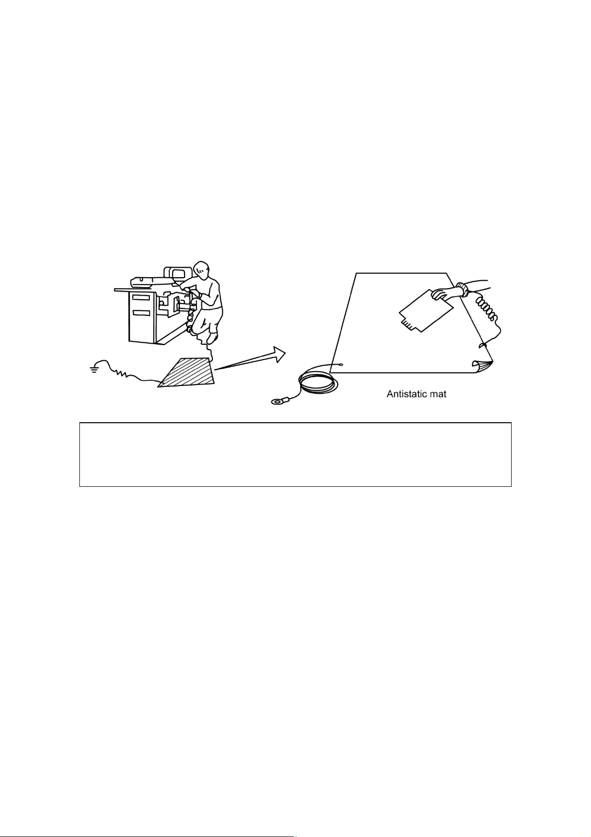
Countermeasures against static electricity
If service work is performed at sites at which countermeasures against static electricity
are not taken, be sure to take countermeasures against static electricity to prevent the
PWBs from being damaged and to ensure quality.
[Examples]
When performing service work such as replacement of PWBs, be sure to wear a wrist
strap.
If PWBs must be put down somewhere, they must be placed on an antistatic mat.
NOTE: Periodic inspection
Be sure to perform periodic inspection to confirm that appropriate countermeasures
against static electricity are being taken (the antistatic mechanism functions normally).
(Perform continuity check.)
<Additional information>
Manufacturer : Sumitomo 3M, Inc.
Model name : 8012J
Product name : Conductive plastic product portable field service kit
Items contained : Antistatic mat ············ 1
Wrist strap ················ 1
4.5-m ground cable ····· 1
No. 2D201-177EN*F
19
Page 20

No. 2D201-177EN*F
20
Page 21

CHAPTER 1
THE X-RAY SYSTEM
No. 2D201-177EN*F
21
Page 22
1.1 Configuration
The X-ray system comprises the following components:
Component Model Features
X-ray high-voltage
generator
X-ray tube CXB-200E Anode heat capacity: 2000 kHU,
CXB-350A/2A Anode heat capacity: 3500 kHU,
1.2 Specifications
The specifications of the X-ray system are given below:
Item Specifications
Radiation method Continuous
Tube voltage
Tube current 10 to 300 mA*1
Radiation time Differs according to the direction from the central system.
80, 100, 120, or 135 kV (3%)
10-mA increments (3-mA increments up to 5%)
(0 to 100 s: 5%)
CXXG-010A/3 Incorporates the control circuit, high-
frequency inverter.
Maximum output of 36 kW
line voltage of 200 V or more)
made by Varian
made by Varian
*1
(42 kW at a
Focus 2 focuses
Anode rotation 2700 min-1 to 3600 min-1 (depending on line frequency).
Power required 3-phase, 200 VAC, 50/60 Hz
Voltage fluctuation Less than 10% (including -5% fluctuation under load)
*1 The maximum output value and the maximum tube current depend on the system
output limit.
For 16-kW systems, the maximum output value is 16 kW and the maximum tube
current is 200 mA.
No. 2D201-177EN*F
22
Page 23
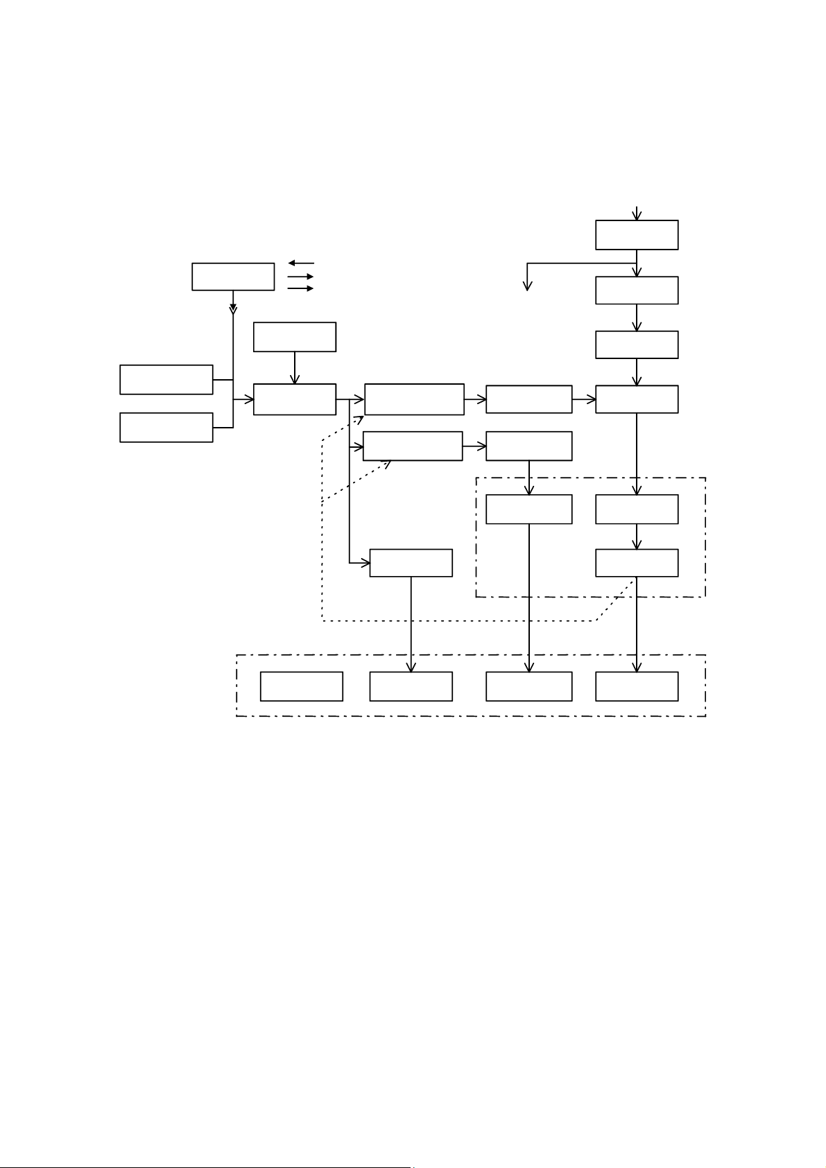
1.3 Principles of Operation
The block diagram of the X-ray system is shown below.
System
communication
Interlock
Control from
outside
Tube voltage
feedback
Tube current
feedback
OLP
management
Operation
control
Door switch
External lamp
Slice counter
Inverter
feedback control
Filament
feedback control
High-voltage
tank
Rotor control
To each
transformer
Inverter driver
Filament
heating circuit
Filament
transformer
3-phase, 200 VAC,
50/60 Hz
Line noise
filter
Rectification
Smoothing
Inverter
High-voltage
transformer
Rectification
X-ray tube
Cooling unit
Block diagram of the X-ray system
FilamentStator coil
Anode and
cathode
No. 2D201-177EN*F
23
Page 24

1.4 Operation Method
Switching of the power supply, the control method as a single unit, and the operating
conditions are explained.
1.4.1 Turning ON/OFF the power supply
Turning ON the power supply
Turn ON the power supply of the
system (console) according to
the normal procedure.
Turning OFF the power supply
Turn OFF the power supply of
the system (console).
*1: The power-ON status may continue for a certain period depending on the DAS
timer setting.
1.4.2 Single unit exposures
Select "DCA test" or "If Remote" from the system maintenance menu at the console
side.
The power is supplied to the gantry, and the
X-ray high-voltage section starts changing the
smoothing capacitor. The main relay is turned on
in about 6 seconds, charging is completed, and the
system becomes ready for operation.
The main relay are turned off and electric discharge
of the smoothing capacitor begins. When heat
build-up of the X-ray tube is high, the gantry power
supply maintains its energized state for cooling.
When the required cooling time elapses, the power
supply will go off automatically.
*1
No. 2D201-177EN*F
24
Page 25
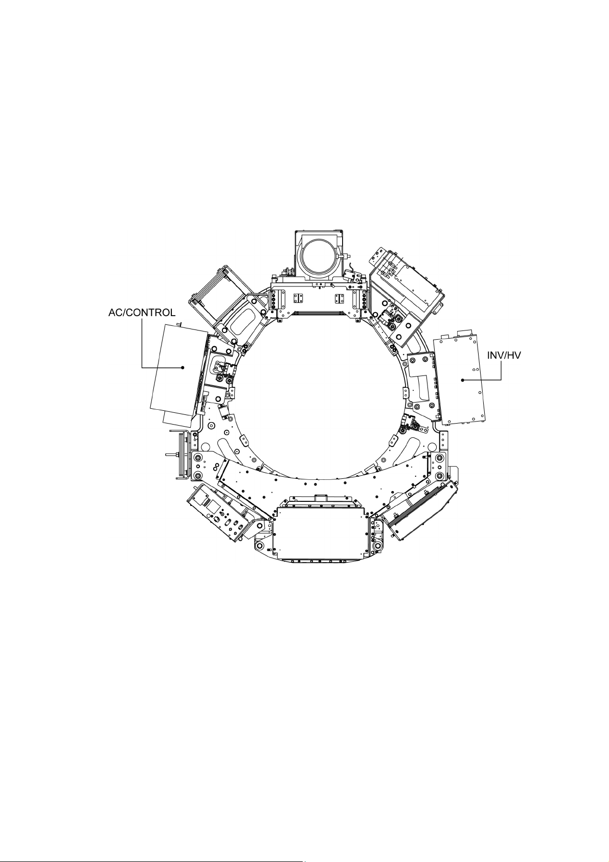
1.5 X-ray High-Voltage Generator
1.5.1 Composition
The configuration of the X-ray high-voltage generator is shown below.
(1) AC/CONTROL section
(2) INV/HV section
(3) Interconnecting cables
X-ray high-voltage generator
No. 2D201-177EN*F
25
Page 26
1.5.2 Operating principle
A three-phase power supply is connected to the AC/CONTROL section.
The input range is from 170 to 230 VAC. The XCS PWB installed in the AC/CONTROL
section functions as an interface with the system.
The AC/CONTROL section outputs approximately 300 VDC. This DC voltage is
supplied to the INVERTER/HV section. The DC voltage is used to supply power to the
inverter and the filament circuit. The output cable of the INVERTER/HV section is
connected to the X-ray tube via the two Federal Standard X-ray connectors. The output
cable from the cathode is also connected to the floating filament of the X-ray tube.
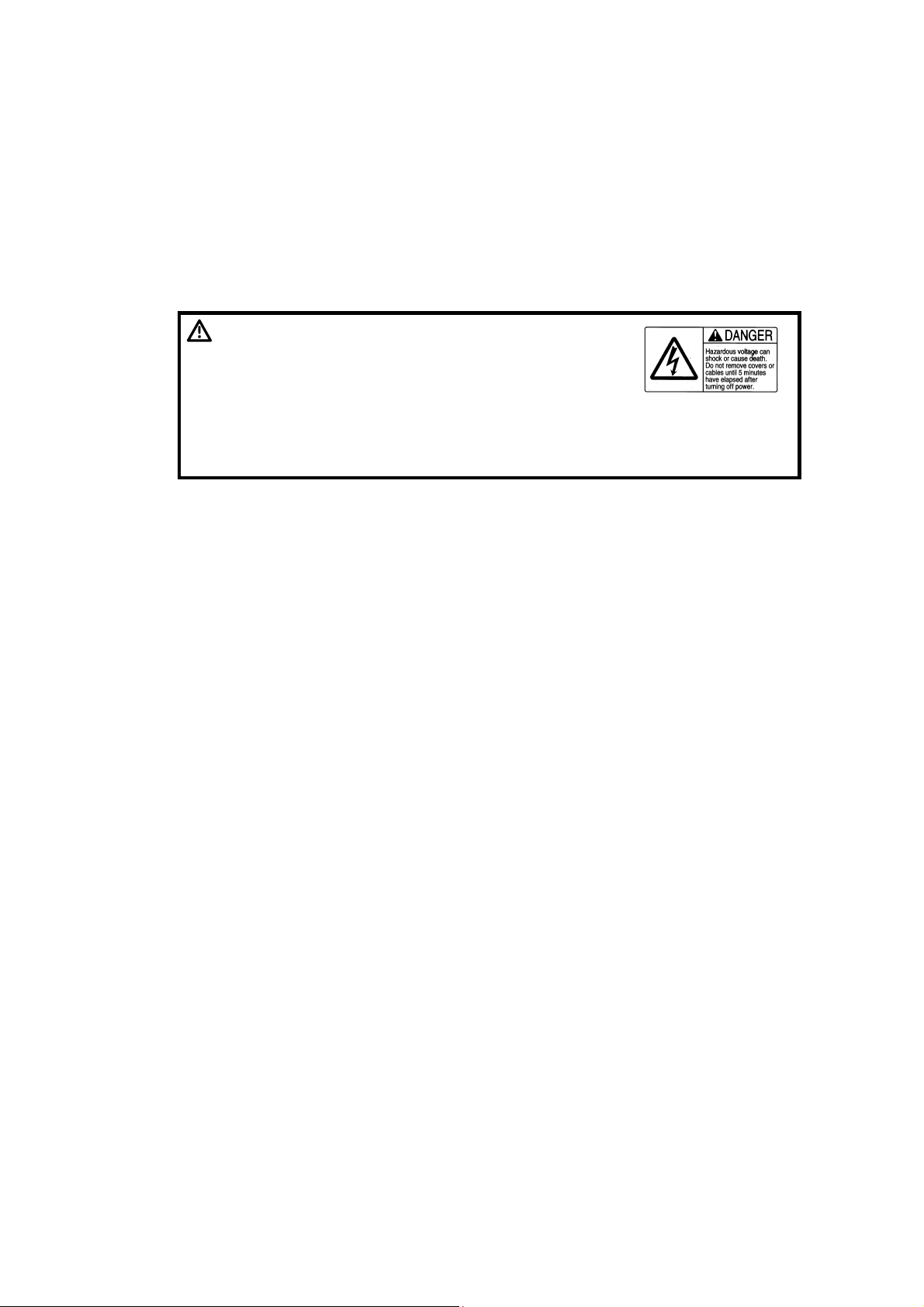
DANGER: Before disconnecting cables or
removing covers, wait for at least 5
minutes after turning OFF the power
supply. Failure to observe this warning
may result in serious injury or death.
The AC/CONTROL and INVERTER/HV sections contain some
parts that are not insulated. A dangerous voltage may be
present even if the contactor is OFF.
No. 2D201-177EN*F
26
Page 27

1.5.3 Operating principle of the AC/CONTROL section
The AC/CONTROL section supplies the required direct current power to the inverter
circuit. The AC/CONTROL section consists of three main subassemblies (chassis
assembly, system control PWB, and AC PWB). Its input is connected to the K1
contactor, the CR1 rectifier, and the DC output connector. The K1 contactor performs
failsafe shutdown of the voltage in the major sections.
(1) AC PWB
The AC PWB has a filtering function, a soft start circuit function, and a monitoring
function.
If a voltage of more than 75 VDC is present in the AC PWB, display is performed
with neon tube DS1.
(2) System control PWB
The system control PWB has an inverter control function, a kV and mA monitoring
function, and an error detection function.
The LED indicator locally displays the status of the generator.
POWER ON : Indicates that +5 V power supply is present in the
system control PWB.
TEST MODE : Indicates that switch SW1 is in test mode.
FAULT (problem) : Indicates that the generator is in error mode. Detailed
data concerning the error is provided by digital I/O.
HV ON (high-voltage ON) : Indicates that a high voltage (more than 10 kV) is
present in the output from the generator.
SPARE : This is mainly used for repair at the factory. This
indicates the phase mode of the inverter. The display
"LED on" indicates outside the phase mode.
FIL ON (filament ON) : Indicates that the filament is ON.
STARTER ON : Indicates that the starter is ON. (Not used)
CONTACTOR ON : Indicates that the contactor is ON.
No. 2D201-177EN*F
27
Page 28
1.5.4 Operating principle of the INV/HV section
The INV/HV section is a DC-DC converter that consists of three main assemblies: the
inverter assembly, the high-voltage multiplier, and the high-voltage transformer.
DC input is applied to the resonance inverter. The inverter operates in phase mode and
frequency mode. The maximum operating frequency of the inverter is approximately
30 kHz. The output of the step-up transformer is approximately 5 kV Pk AC. This is
supplied to the two half-wave multipliers. These multipliers comprise a double-voltage
rectification circuit. The input voltage is sequentially doubled by the serially connected
multipliers.
The rated output of the multiplier is a DC voltage of ±70 kV. This is supplied to the
X-ray tube. The INV/HV section is connected to the AC/CONTROL section via the
control cable and the DC power cable.
(1) Inverter assembly/inverter PWB
The inverter assembly contains the inverter heat sink, the cooling fan, the DC input
connection section, the IGBT, and the inverter PWB.
WARNING: The gate drive circuit and the IGBT inverter circuit are high-
voltage circuits. Do not perform repair or maintenance work
on these circuits and do not attempt to measure these
circuits using a probe. If it is necessary to touch them, be
sure to first check that there is no DC voltage relative to
earth (chassis) using a tester or equivalent device.
NOTE: No calibration is required on site. The generator can be repaired without
performing recalibration. The inverter assembly and the high-voltage module
are components that cannot be replaced on site. Calibration of the highvoltage module is performed by the inverter PWB. Therefore, the high-voltage
module and the inverter PWB cannot be replaced individually.
If a power supply of more than 75 VDC is present in the inverter PWB, the neon
tube lights.
(2) High-voltage module
This high-voltage module contains the high-voltage multiplier, the high-voltage
feedback divider, the filament transformer, and the anode/cathode connectors.
The high-voltage module is fully encapsulated. As described in the previous
subsection, the high-voltage module is not replaceable on site.
No. 2D201-177EN*F
28
Page 29

(3) XCS PWB
PX71-07786 Gr.2
Part Name XCS2
PWB No. YWM1634
ROM No. C10051-XX
Connection diagram 3XW71-1848
Mounting position Within the AC/CONTROL section
Functions
Communication control Y
Output of basic control signals Y
Monitoring of internal status Y
Selection of output voltage and
Y
current
Tube current modulation control Y
(Sure Exposure,
Sure Exposure 3D
(XY modulation)
*1
)
Control of OLP Y
Holding of power supply for
Y
cooling the X-ray tube
Backup of the basic information
Y
memory
Control of the slice counter Y
Control of the dedicated starter Y
*1: Sure Exposure 3D is enabled only when a system supporting this function is
used in combination.
No. 2D201-177EN*F
29
Page 30
1.6 Outline of the X-ray Tube System
This subsection describes the configuration and specifications of the X-ray tube system.
1.6.1 Configuration
The X-ray tube system comprises the X-ray tube unit and the heat exchanger, which are
connected via the cooling oil circulating hose. The X-ray tube is mounted on the gantry
rotation section. They cannot be separated because of air-tight structure.
Hose
1.6.2 Specifications
Model
Anode heat capacity (kHU) 2000 3500
Anode cooling rate (kHU/min)
(maximum)
Maximum tube voltage (kV) 150 140
Dimensions of the focus (mm)
(Pinhole method)
(Slit method)
X-ray tube mass (kg) Approx. 33 Approx. 34
Heat exchanger mass (kg) Approx. 17 Approx. 17
X-ray tube unit
CXB-200E,
Varian GS-2078/A
252 285
Small: 0.9 0.9
Large: 1.5 1.0
Small: 1.1 1.3
Large: 1.7 1.7
Heart exchanger
CXB-350A/2A
Varian GS-3078/A
Small: 0.9 0.9
Large: 1.5 1.0
Small: 1.1 1.1
Large: 1.7 1.7
No. 2D201-177EN*F
30
Page 31

100
Varian 2000/3500 kHU tube, OLP=100%
%
90
80
70
60
50
CXB-350A/2A
40
30
20
10
0
CXB-200E
60565248444036322824201612840
64
min.
Cooling curve
No. 2D201-177EN*F
31
Page 32

1.7 Overload Protection (OLP) Management Functions
This subsection outlines the overload protection (OLP) management functions of the
X-ray tube system.
1.7.1 Functional description
The X-ray tube system supports the OLP management functions for:
(1) Calculation and monitoring of the anode heat capacity for protection
(2) Short-term monitoring of the rating for protection of the focus
(3) Short-term monitoring of the nominal rating for protection of the focus
Items (1) to (3) are calculated continuously to check the required radiation conditions. If
the radiation conditions exceed the calculated OLP, the system is notified and radiation
is halted. These three items are calculated, managed, and controlled by the XCS PWB
micro-computer. The following subsections give details of items (1) to (3).
1.7.2 Calculation and monitoring of the anode heat capacity
The function is used to protect the anode from overheating.
The current anode heat capacity is calculated from the cooling curve data of the X-ray
tube stored in memory, the anode heat capacity value obtained during the last exposure,
and the elapsed time after radiation.
The anode capacity is calculated when the currently required radiation conditions are
used, and is compared with the calculated limit.
If the calculated anode capacity exceeds the limit, the required waiting time is calculated
and communicated to the system, and SET UP processing is inhibited.
The anode heat capacity and time are retained in memory when the power is turned
OFF.
The residual heat capacity is calculated from backup data and is used as the initial
value of the anode heat capacity when the power is turned ON.
1.7.3 Short-term monitoring of the rating
This function is used to protect the focus from overheating during continuous radiation.
The radiation limit is obtained from the radiation conditions required from the data
concerning "output vs continuous radiation limit" stored in memory.
If the required radiation time exceeds the limit in REMOTE mode, the required radiation
conditions are assumed to be invalid and the system returns a negative response.
No. 2D201-177EN*F
32
Page 33

1.7.4 Short-term monitoring of the nominal rating
This function is used to protect the focus from overheating during continuous radiation
and is applied to a radiation time of less than 5 seconds using the same kV and mA.
When kV and mA are set, the cumulative limit is obtained during repeated exposures
from memory data.
If the next exposure is performed less than 5 seconds after the previous exposure, the
cumulative radiation time is added. If the elapsed time after the previous exposure is 5
seconds or more, the cumulative time is cleared.
When "cumulative time + required radiation time" exceeds the cumulative limit less than
5 seconds after the previous exposure, the residual time is calculated for
communication with the system. During this period SET UP processing is inhibited.
(Example)
5 seconds
or more
3 seconds
A
5 seconds
or more
3 seconds 3 seconds 3 seconds 3 seconds
B
C
Less than
5 seconds
Short-term monitoring of the nominal rating
Scan A calculated during a radiation time of 3 seconds
Scan B calculated during a radiation time of 3 seconds
Scan C calculated during a radiation time of 6 seconds
Scan D calculated during a radiation time of 9 seconds
Scan E calculated during a radiation time of 12 seconds
DE
5 seconds
or more
No. 2D201-177EN*F
33
Page 34

1.8 Tools and Instruments
The table below shows tools and measuring instruments required for installation, check,
adjustment, and repair of the X-ray system.
Tools and instruments for the X-ray system
Instal-
lation
(1) Tube voltmeter
(2) Tube ammeter
(3) Digital storage-type
Check and
adjustment
Repair Remarks
oscilloscope
(4) Torque wrench
(5) Tube voltmeter
(6) Silicone plate
(7) Silicone compound
(8) Absolute alcohol
(9) Toothbrush
kV-201 or kV-201D (manufactured
by ARCO Electric)
MA-1201D (manufactured by
ARCO Electric)
*2
*1
For fixing the high-voltage cable
For fastening the resonance
capacitor terminal
AB-201515D (manufactured by
TOREK)
*3
BSX71-0752E*4
TOSLUBE 42 TSK5542
(AZP393-01) or one provided with
the Varian X-ray tube
Used for cleaning
Used to apply the silicone
compound coating to the inner wall
of the receptacle
(10) Torque driver
*1: The MA-1201 is not used because the waveform at a neutral point contains a large
amount of high-frequency ripple, which makes measurement less precise.
*2: Also used for adjustment of tube currents (set-up) and waveform checks.
*3: Used instead of the tube voltmeter (1) and the tube ammeter (2).
*4: Silicone plate and silicone oil to be used for the CLAYMOUNT high-voltage cable
KANON 20LTDK
No. 2D201-177EN*F
34
Page 35

1.9 Notices
This section describes important safety and protection notices pertaining to work on the
X-ray system.
1.9.1 Floating section
The power supply circuit of the X-ray high-voltage generator is not insulated from the
power supply. If you should touch areas other than the designated spots or connect
measuring instruments, take adequate precautions against electrical shocks and short
circuits.
1.9.2 Power cable
When disconnecting the power cable, first unplug it from the power distribution board.
If the power cable is unplugged at the other side, it is very dangerous if the power is
turned ON.
Always disconnect the grounding wire last.
When connecting the power cable, first connect the grounding wire, connect the other
wires to the device, then connect the wires to the power distribution board.
PS
Handling the power cable
Device
Do not leave the device
with the end of the cable
open.
No. 2D201-177EN*F
35
Page 36

1.9.3 Precautions for rotation
As the X-ray high-voltage generator is mounted in the gantry rotation section, make
sure that no worker is caught in the rotation section during maintenance.
DANGER: 1. When servicing is to be performed with the gantry cover
open, be sure to turn OFF the power of the system at the
distribution board and wait for 5 minutes or more to
prevent workers from receiving electric shocks or being
injured due to unexpected system operations.
2. If it is necessary to perform servicing with the system
turned ON, supply power only to the required parts. At the
same time, take safety measures such as turning OFF the
power of the cover switch and CP320 (power to the rotation
servo motor).
WARNING: When disconnecting the cables, take note to ensure correct
reconnection. In particular, inappropriate routing of the
power cable will cause interface with other cables, which
may adversely affect system performance.
CAUTION: When rotating the rotation section manually, be sure to release the brake
before rotating the rotation section. Rotating the rotation section without
releasing the brake may result in system malfunction.
When the power of the gantry is turned OFF, the brake of the rotation section is
engaged. To rotate the rotation section to the desired position, follow the specified
procedures.
No. 2D201-177EN*F
36
Page 37

1.9.4 Handling the high-voltage cable
This subsection describes the handling of the X-ray tube and the INV/HV bushing
section, and the procedure for replacing the silicone plate.
DANGER: When disconnecting the
high-voltage cable,
observe the following to
fully discharge its residual
charge in order to ensure
safety during servicing
work.
Turn power OFF and wait 10 minutes or more.
When the high-voltage cable has been disconnected,
simultaneously ground two of the three pins at the top of the
bushing in all three combinations. Repeat all combinations
twice or more.
Do not touch the top of the bushing.
Place a cap, vinyl cover, etc. over the tip of the bushing to
protect it.
1.9.4.1 Removing the high-voltage cable
(1) Wait 10 minutes or longer after the power is turned OFF, then start this procedure.
(2) Remove the cable from the high-voltage transformer side first and then on the
X-ray tube side. If only the cable from the X-ray tube needs to be disconnected for
X-ray tube replacement, etc., be sure to perform the discharge procedures
described in step (4) below before touching the tip of the electrode.
(3) When removing the high-voltage cable, loosen the setscrews and flange and hold
up the rim of the bushing with a bladed screwdriver.
Remove the bushing after the electrode is removed. Never extract the bushing by
pulling on the cable.
Lift
Correct
Incorrect
No. 2D201-177EN*F
37
Page 38

(4) After pulling out the bushing, short each of the three pins at the top of the electrode
to the grounded chassis. Repeat this procedure at least twice. Then, short every
combination of two pins among the three pins at the end of the bushing. Use a
screwdriver for shorting. Short each of the three pairs two or more times.
Be sure to short the pins as described above because a high voltage may remain.
(5) Remove both ends on the anode and cathode sides.
1.9.4.2 Cleaning
(1) Prepare a new silicone plate and clean it with absolute alcohol.
When no absolute alcohol is available, wipe the plate thoroughly with a clean cloth.
Replace the used silicone plate with a new one.
If there are any discharge stains which cannot be removed from the silicone plate,
it must be replaced. Stains may cause defects such as discharge.
Clean the pins so that any metal powder or dust is completely removed.
(2) Also clean inside the receptacle. Be sure to remove dust around the inner
electrode.
1.9.4.3 Applying silicone oil (CLAYMOUNT high-voltage cable)
(1) Clean the high-voltage cable plug, the inside of the socket in the X-ray tube, and
the silicone plate with absolute alcohol.
(2) Place the ring nut at the base of the plug by passing the plug through the ring nut.
Attach the supplied polarity labels ((+) and (-)) to the cable.
(3) Mount the partition flange on the ring flange of the high-voltage cable with screws.
(4) Apply silicone oil to the rubber gasket and place it at the ring flange by passing the
plug through it.
(5) Apply silicone oil to both sides of the silicone plate and attach it to the tip of the
plug.
The purpose of applying silicone oil is to smoothen and moisturize the surface of
the silicone plate, enabling closer contact. A small amount of silicone oil should be
applied and spread evenly.
Silicone oil need not be applied to the side of the plug. Note that silicone grease
(Toslube) must not be used. If it is applied, contact with the silicone plate will be
poor, possibly leading to a deterioration in the withstand voltage.
(6) Insert the plug with the silicone plate into the socket to make the connection. Then
tighten the ring nut.
Note: To achieve close contact with the silicone plate, firmly tighten the ring nut.
(7) Tighten the setscrew of the ring nut. Use a hexagonal wrench for M3 setscrews.
No. 2D201-177EN*F
38
Page 39

Screw (2 locations)
Rubber gasket
Silicone plate
Plug
Ring flange
Partition flange
Sleeve
Polarity label
Setscrew
Ring nut
Cable
Silicone oil
The surfaces must
be in close contact.
(8) Be sure to tighten the screws again after X-ray tube seasoning is completed,
because the screws may become loose when the X-ray tube is heated and then
cooled.
Also, perform additional tightening at the time of inspection.
No. 2D201-177EN*F
39
Page 40

1.9.5 Replacing the fuse
When replacing the fuse, be sure to use a fuse with the same rating and type specified.
WARNING: For continued protection against
risk of fire, replace only with
same type and rating fuse.
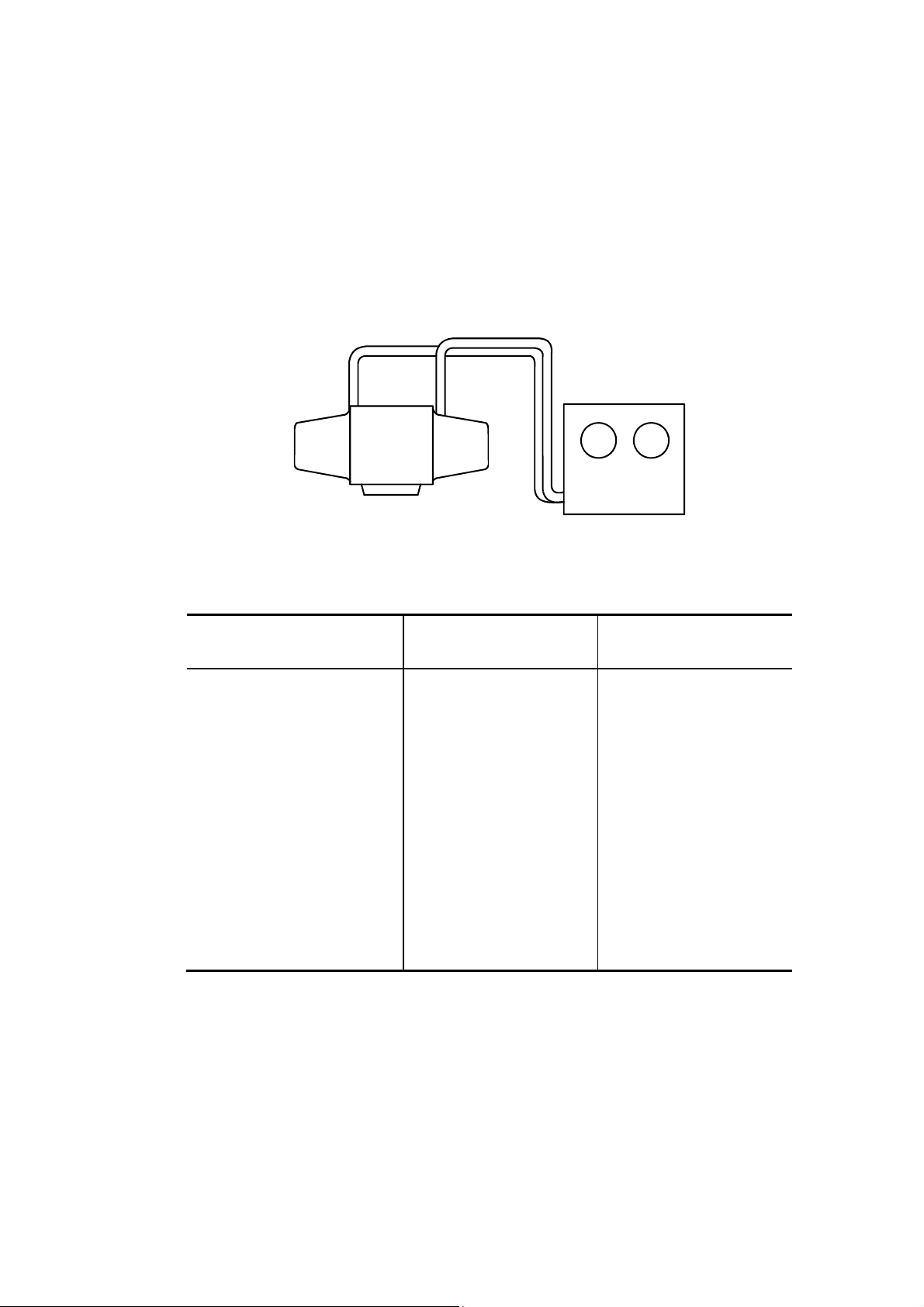
1.9.6 Using the tube voltage meter
Prepare a high-voltage bleeder (Arco Electrical Machinery kV-201 or equivalent), and
connect between the high-voltage unit and the X-ray tube as shown in the figure below.
For details, refer to the operation manual of the tube voltage meter. Set FUNCTION to
INT.DELAY TIME 10. (The tube voltage after 0.1 s is displayed.)
High-voltage
transformer
When a Torek AB-201515D is used, perform the same connection.
High-voltage cables of
the system
EE
Signal cable
kVp
meter
Connection of the tube voltage meter
High-voltage cables
provided with the kV-201
Oscilloscope
Tube voltage
waveform check
TubeBleeder
With the Torek AB-201515D, the tube voltage and the tube current can be measured
concurrently.
No. 2D201-177EN*F
40
Page 41

1.9.7 Tube ammeter
Connect a tube ammeter (MA-1201D manufactured by ARCO or equivalent) between
the anode of the high-voltage transformer and the anode of the X-ray tube. Set
FUNCTION to RAD.DELAY TIME 4X10. (The tube current is displayed after a delay of
0.4 seconds.)
The measured value is the current on the anode side. The method for calculating the
tube current for the cathode side differs depending on the tube used as described below.
High-voltage
transformer (built
into the X-ray
high-voltage
generator)
Tube ammeter detector tank
Transformer
side
Tube
side
X-ray tube
Connection of the tube ammeter
For the CXB-350A and CXB-200E
Tube current (on cathode) =
Reading of the MA-1201D (anode-side tube current)
Ammeter (mA)
0.88
No. 2D201-177EN*F
41
Page 42

1.9.8 Other
(1) Power cannot be supplied only to the X-ray system. Since the system has no
operation section other than the console, it must be started up even if maintenance
is performed only for the X-ray system.
(2) A center-metal X-ray tube is used. Therefore, be sure to ground the center metal
potential.
(3) The system has a large capacitor (approx. 300 VDC, 36000 F) at the primary side.
Therefore, wait for at least 5 minutes after turning OFF the power of the system
when removing the cover, etc. In addition, confirm that no electrical charges
remain before touching the main circuit (including the floating section). (Check
point: between P2 and N2 of the inverter section)
(4) Never apply a high voltage to a cold X-ray tube (the filament is not heated)
regardless of whether the high-voltage cable is connected or disconnected.
Otherwise, the X-ray tube will be damaged.
When the positive
side is disconnected,
Damage to the X-ray tube
(5) Since the tube voltage (kV) is fed back to the X-ray system, it is impossible to
check the high-voltage circuit with no load (without the X-ray tube).
Use a test tube to isolate a tube-related problem (e.g., OVER mA error).
a strong current flows as shown
damaging the X-ray tube.
No. 2D201-177EN*F
42
Page 43

1.10 Replacing the X-ray Tube
1.10.1 Connection and operation check
(1) Connection and operation check
(a) Change of the output voltage to the X-ray tube
Perform connections at terminal board TBX11 and at the internal terminal
board of the AC/CONTROL as described in the table below according to the
X-ray tube used in combination (CXB-200E and 350A for Alexion).
The connection with the X-ray tube is shown in the figure on the next page.
X-ray tube
TBX11 terminal
(heat exchanger unit)
AC/CONTROL internal terminal board TB1
CXB-200E Nos. 4 and 5 (110 V) VARIAN side
(orange cable -110 V, yellow cable - 65 V)
CXB-350A Nos. 4 and 6 (200 V) VARIAN side
(orange cable -110 V, yellow cable - 65 V)
TBX11
1
2
3
4
5
6 HEAT EXCH_200V
TOSHIBA
VARIAN
100 V
80 V
110 V
65 V
200 V
COM
Purple
Blue
Orange
Yellow
Red
White
TB1
80/65 V RUN
Yellow
Orange
COM
100/110 V
200 V
(b) XCS PWB setting change (settings of the OLP and the focus)
<For XCS2 PWB>
STATOR_COM
MAIN
PHASE
HEAT EXCH_COM
HEAT EXCH_110V
X-ray tube S2-1 S2-2 S2-3 to -8
CXB-200E ON ON OFF
CXB-350A ON OFF OFF
No. 2D201-177EN*F
43
Page 44

No. 2D201-177EN*F
44
Connection diagram for Varian X-ray tube
Page 45

(2) If adjustment (80 kV/100 kV)
Perform If adjustment for 80 kV and 100 kV using the If value remote adjustment
function.
Confirm that the name of the X-ray tube used is displayed in the 'Tube Information'
column.
(3) Seasoning
(4) If adjustment (120 kV/135 kV)
Use the If value remote adjustment function to adjust the If value only for the
conditions of 120 kV/135 kV.
(5) X-ray tube alignment
No. 2D201-177EN*F
45
Page 46

1.10.2 X-ray tube aging
Perform the aging operation from the console.
(1) Select the aging menu and perform it at the console.
(2) Stop 30 minutes or more after exposure is performed. (Leave the system with the
power turned ON.)
NOTE: The scan conditions for X-ray tube warm-up and seasoning are shown below.
For the scan conditions for warm-up, air calibration may be added depending
on the system software settings.
<For CXB-350A>
For warm-up:
100 kV, 250 mA, 4-s exposure, 6-s pause 20 times
100 kV, 250 mA, 4-s exposure, 30-s pause 4 times
For seasoning:
100 kV, 250 mA, 4-s exposure, 6-s pause 20 times
30-s pause
100 kV, 250 mA, 4-s exposure, 30-s pause 10 times
<For CXB-200E>
For warm-up:
For systems with output limited to 16 kW
80 kV, 150 mA, 4-s exposure, 15-s pause 3 times
100 kV, 150 mA, 4-s exposure, 15-s pause 4 times
120 kV, 100 mA, 4-s exposure, 15-s pause 1 time
120 kV, 130 mA, 4-s exposure, 15-s pause 2 times
100 kV, 160 mA, 2.5-s exposure, 18-s pause 20 times
For 36-kW systems
80 kV, 150 mA, 4-s exposure, 15-s pause 3 times
100 kV, 150 mA, 4-s exposure, 15-s pause 4 times
120 kV, 100 mA, 2-s exposure, 15-s pause 1 time
120 kV, 200 mA, 2-s exposure, 15-s pause 1 time
120 kV, 300 mA, 2-s exposure, 15-s pause 1 time
100 kV, 200 mA, 2-s exposure, 18-s pause 20 times
For seasoning:
100 kV, 150 mA, 6-s exposure, 15-s pause 15 times
45-s pause
100 kV, 150 mA, 6-s exposure, 45-s pause 6 times
No. 2D201-177EN*F
46
Page 47

1.10.3 If adjustment
The If value remote adjustment explained below is carried out to smooth out the leading
edge of the tube current. Normally, If adjustment is performed while monitoring the tube
current waveform (TP6 on the SYSTEM-CONTROL PWB).
If the mA waveform on the oscilloscope does not match the If value shown in the figure
below, adjustment is performed automatically.
The smallest overshoot is considered O.K. condition.
Large If
Value decreases
Small If
Value increases
(1) Starting the If value remote adjustment function
Select [If] from the <<System maintenance>> menu by clicking the mouse, to carry
out the remote exposure adjustment of the If value from the Navi-port. The If value
remote adjustment program will start up.
Engineer Utility
Menu
Password entry
Engineering
DCA
If Remote
No. 2D201-177EN*F
CANCEL
(The first page)
47
Page 48

(2) Initial screen display and If value data reading
When the program starts up, the following view port screen is displayed on the
monitor (hereinafter the view port is abbreviated to "vp".)
If value data reading vp screen
Read the If value data used first. Select the medium in which the If value data
used is to be stored and saved.
(The XC information and the tube information currently displayed on the screen
represent the ID information of the XC and the X-ray tube currently connected. If
the connection is not carried out, "******" is displayed.)
Tube Information CXB-200E 2000 kHU/100%
CXB-350A 3000 kHU/100%
[Unix File] : Reads the If value data saved on the console (hereinafter referred to
as "Unix File") in the format specified in advance. (Item (a))
[Standard] : Reads from the standard If value storage file for recommended If
values, the data under the kV/mA conditions predetermined by
Toshiba. (Item (b))
[XC] : Reads the If value data currently set in the XC memory via SS.
(Item (c))
[QUIT] : Closes the If value data reading vp, and the screen returns to the If
value Remote Adjustment vp.
No. 2D201-177EN*F
48
Page 49

(a) If value data read from the Unix File
When If value data read from the Unix File is chosen, the following If value
read vp is displayed. Specify which file containing IF value data is to be read
from the directory.
Read vp screen
Only the directories with file extension "---.ifs" are displayed. (Indicates If
value data.)
In addition, the function of each soft key is as follows:
[Cancel]: Closes the Read screen and the system returns to the If value
Remove Adjustment screen.
[OK] : Executes the read processing.
When Read is completed normally after [OK] is clicked, the If value data read
from the Unix File is displayed in the If column on the vp.
(b) Reading standard If value data
Read If value data from the file in which the recommended If value preset in
the system is saved.
When data read from the standard value file is completed normally, the
standard value will be displayed in the If column in the If value Remote
Adjustment vp. (The value is the same as that of the Std. column.)
(c) Reading the If value data from the XC memory
Read the If value data from the If value table currently set in the XC memory
via SS.
When reading from the XC memory is completed normally as well as (b), the
value read from the XC memory is displayed in the If item in the If Remote
Adjustment vp.
No. 2D201-177EN*F
49
Page 50

(3) Preparation for If value exposure adjustment
Check the validity of the value by performing an actual X-ray exposure using read If
value data. If the value is not appropriate, update the If value, check the validity of
the updated value again, and calculate the appropriate If value. In order to perform
the If value exposure adjustment, the following must be taken into consideration.
<1> Which combination of tube voltage (kV), tube current (mA), and focal size is
the target for If value exposure adjustment? <Selecting the exposure
adjustment conditions>
<2> What is the initial value of If value when If value exposure adjustment is
performed? <Setting the If value>
<3> Should the If value which is not the target of adjustment be interpolated
using the adjusted If value?
<Whether or not interpolation should be performed>
(a) If value Remote Adjustment vp
If value Remote Adjustment vp screen
When the If value data is read, the If value data list of the lowest tube voltage
conditions (80 kV) is displayed. The following value is displayed on each field
on the vp.
No. 2D201-177EN*F
50
Page 51

<XC info.> : XC firmware version (10 bytes), which is obtained via SS,
is displayed.
<Tube info.> : The X-ray tube identification code (10 bytes), which is
controlled by the XC via SS, is displayed.
For CXB-200E [2000 kHU/100%]
For CXB-350A [3000 kHU/100%]
<Tube Voltage>: The tube voltage to be adjusted (kV) is selected.
80, 100, 120, 135 kV
<Focus Information>
: The focus to be adjusted is selected.
Large, Small
<mA/If Table> : The tube current and If value data are displayed as
decimal values.
mA ; Tube current value
Std. ; Standard If conversion value
If ; If conversion value
adj.if ; If conversion value after adjustment (interpolation
calculation data is also included.)
* If value information for which the combination of kV and
mA is impossible becomes std., and "---" is displayed in
the If column.
The functions of the soft keys which are on each vp are as follows:
[Adjust] : Executes If value exposure adjustment of the selected
adjustment conditions.
However, the adjustment must be controlled and
performed under the conditions (mA/focus size) for the
same tube voltage level automatically. (Item (4))
[Write] : Saves or stores the If information currently displayed to
the Unix File or the XC memory. (Item (5))
[Read] : Reads If value information from the Unix File or the XC
memory, or converts If value data to the standard value.
(Item (6))
[QUIT] : Closes this vp, the help vp, and the error vp, and quits If
value remote adjustment processing.
: Used for scroll-control of If value information (data display
for 10 lines) currently displayed. Information for the
previous 10 lines can be displayed using
, and
information for the next 10 lines can be displayed using
.
No. 2D201-177EN*F
51
Page 52

(b) Selecting the exposure adjustment conditions
Use the following procedure to select the conditions for If value exposure
adjustment.
Selecting the conditions to be combined
To adjust a specific tube current condition, click the tube current to be
adjusted. The clicked tube current is highlighted as shown in the figure above
(250 mA and 300 mA are selected in the figure), indicating that the clicked
tube current can be adjusted.
To cancel the specified conditions used in combination, click the specified
conditions again. The highlighted tube current conditions are released.
No. 2D201-177EN*F
52
Page 53

(c) Setting If conversion value data
The If conversion value data can be changed as follows:
When the If conversion value data to be changed is clicked, the item is
highlighted and the following "If Value Entry" vp is displayed. Perform If
conversion value change on this entry vp.
Setting the If conversion value
If another line is clicked when the entry vp is displayed, the entry vp is closed,
then the clicked item is highlighted and the entry vp is displayed again.
The numerical value which can be entered is from 1 to 256.
(4) If value exposure adjustment processing [Adjustment]
When the [Adjustment] key is clicked on the If value Remote Adjustment vp, the
following vp will be displayed; the If value following the X-ray exposure can be
checked, and the If value interpolation can be calculated.
If value Exposure Adjustment vp screen
No. 2D201-177EN*F
53
Page 54

The displayed menus are as follows:
<Exposure conditions>
Tube kV : If tube voltage for adjustment
Tube mA : If tube current for adjustment
Focus : If focus for adjustment
Exp. time : X-ray exposure time (fixed to 0.2 second)
<If value to be set>
If value : The If conversion value stored in the XC memory at the time
of adjustment. During adjustment, it is updated automatically.
The numerical value in [ ] becomes the value preset for If
value adjustment, that is, the initial value at the time of
adjustment. By comparing the set value with the value
displayed on the left, the difference can be checked.
<No. of adjustment>
Remain : The number of adjustments for the same tube voltage is
displayed as the remaining number of adjustments.
(a) Calculating the number of exposure adjustments
The number of adjustments and the order in which they are carried out is
determined from the exposure adjustment conditions specified in (3).
(b) Setting the window limit value of the XC monitor mode
The window limit (maximum/minimum) value is calculated from the If value to
be adjusted, and the result is displayed on the If Exposure Adjustment vp as
well as the Setting If value vp. Moreover, the value is sent to the SS as a
request for switching from XC monitor mode to If value check mode.
(c) Setup of If conversion value data
In order to send If conversion value data of the tube voltage/tube current/focal
size for which exposure adjustment is performed to the XC memory via SS,
the request text of XC memory write is issued to SS.
(d) Preparation for X-ray exposure
The request for warm-up scan is issued to the scan manager with the exposure
adjustment conditions (note that scanning is performed only once.)
(e) Exposure adjustment start
Warm-up scanning is performed once by pressing the [Start] button.
No. 2D201-177EN*F
54
Page 55

(f) Interruption processing during If value exposure adjustment
Interruption processing during exposure adjustment is as follows:
<Exposure interruption by the [Interruption] key>
To stop temporarily the exposure adjustment, or to perform "Interpolation
Calculation" processing, press the [Interruption] key. The "Interruption"
message is sent from the scan manager, and the following message vp is
displayed to ask whether the system should perform "Interpolation
Calculation" processing or should interrupt exposure adjustment.
Do you want to stop If value exposure
adjustment?
Or, perform interpolation calculation?
Execute
adjustment
Interpolation
calculation
Interrupt
adjustment
Exposure interruption vp screen
[Execute adjustment] : After closing the exposure interruption vp, the
system returns to a status where it waits for
instructions to start If value exposure adjustment
under the conditions used in the adjustment
performed last.
[Interpolation calculation] : If there are two or more If value data for which
exposure adjustment was performed, this soft
key becomes active. When the key is clicked,
the interpolation processing check vp shown in
item (g) is displayed and the system asks
whether it should perform interpolation
calculation processing.
[Interrupt adjustment] : When, after the Exposure Interruption vp and the
If value Exposure Adjustment vp are closed,
there is even one If value data adjusted using the
exposure adjustment, the Adjustment Result
Check vp of item (j) will be displayed and it will be
decided whether to employ the If value data.
If exposure adjustment was not performed, the
system returns to the If value Remote Adjustment
vp.
No. 2D201-177EN*F
55
Page 56

(g) Asking whether the system should perform interpolation calculation (at the
time of interruption)
The system replaces If value data not adjusted with interpolation calculation
data, using the If value already exposure-adjusted which is displayed in the
"adj.If" column on the If value Remote Adjustment vp. Select whether or not
the system should perform interpolation processing, using the following
interactive vp. The scroll key on If value Remote Adjustment vp can be used.
Interpolation Processing Check vp screen
[No] : The system closes the Interpolation Processing Check vp without
performing interpolation, and it returns to the Exposure Interruption
vp.
[Yes] : The system closes the Interpolation Processing Check vp shown
above and performs interpolation processing displaying the message
vp. After completing the interpolation, the system closes the
message vp, displays interpolated If value in the "adj.If" column on
the If value Remote Adjustment vp, and returns the Exposure
Interruption vp.
Non-adjusted If value to be interpolated is the value between the
minimum mA and the maximum mA of the adjusted If value conditions.
The method used is the primary interpolation method using two
continuous data.
No. 2D201-177EN*F
56
Page 57

(h) Reading and judging the If value check result
In order to obtain the result of If value check from the XC, the reading request
text of XC and X-ray conditions (U status) is issued to SS.
<1> Check result O.K.
Since If value data currently set is O.K. when the If value check result
data is 0, the system returns to item (b) "Setting the window limit value
of XC monitor mode" if there are other exposure adjustment conditions.
In this case, the system displays the If value checked in the "adj.If"
column of the If value Remote Adjustment vp. If Exposure Adjustment
at the same tube voltage is completed, the system closes the If value
Exposure Adjustment vp and goes to item (i) "Asking whether the
system should perform interpolation calculation (when adjustment is
completed)".
<2> Check result error
When the If value check result data is 1 or 2, set the If conversion value
again and repeat adjustment as described below. The following
messages are displayed to indicate the errors detected during the
check. After this, the system returns to item (b) "Setting the window
limit value of XC monitor mode" and it waits for the [Start] button to be
pressed again.
When data is 1: Since it exceeds the maximum, increase the If
conversion value by 1.
Previously detected If value exceeded the
upper limit.
When data is 2: Since it is below the minimum, decrease the If
conversion value by 1.
Previously detected If value exceeded the
lower limit.
No. 2D201-177EN*F
57
Page 58
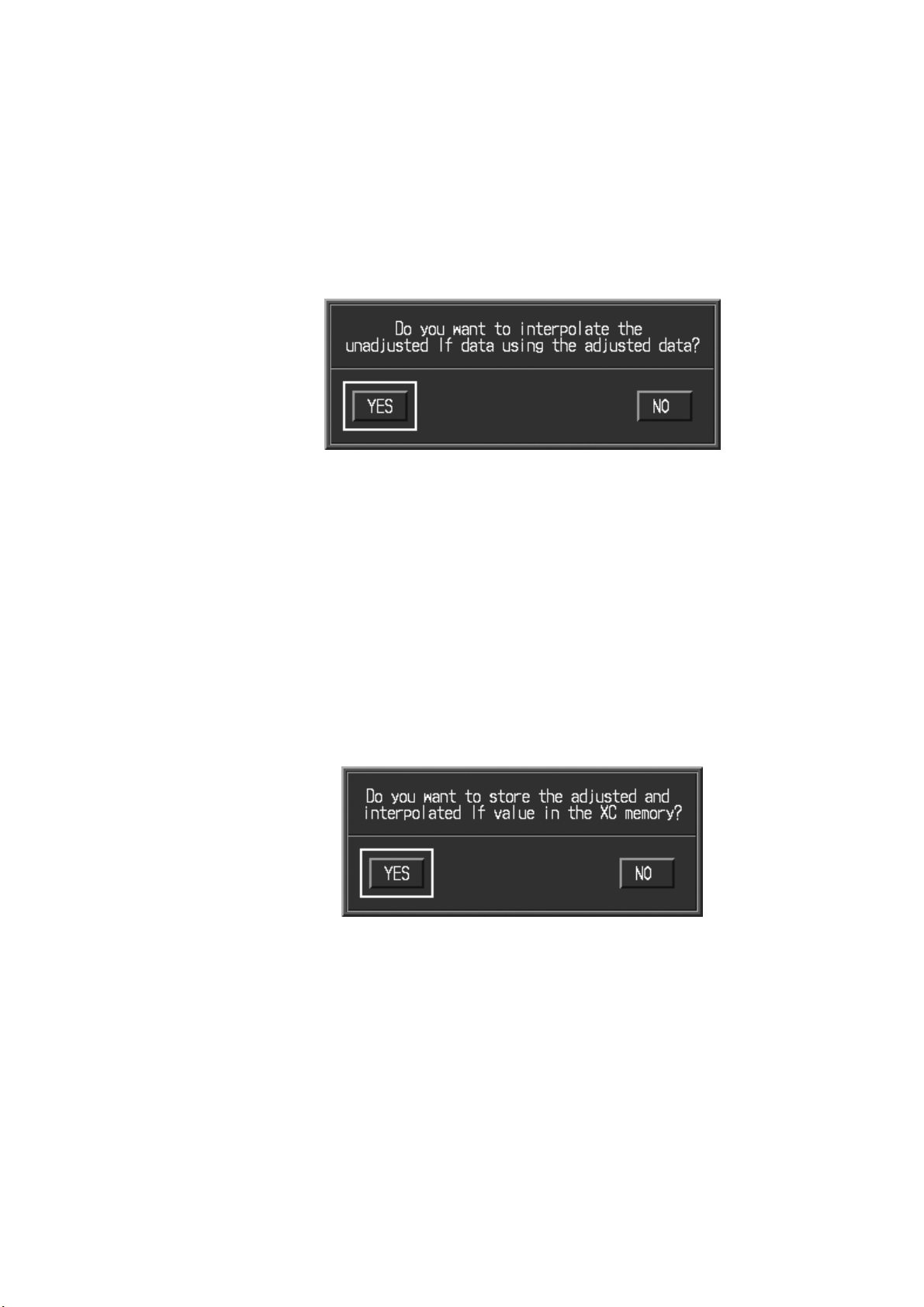
(i) Asking whether the system should perform interpolation calculation (when
adjustment is completed).
The system replaces non-adjusted If value data with interpolation calculation
data, using the If value already exposure-adjusted which is displayed in the
"adj.If" column on the If value Remote Adjustment vp. Select whether or not
the system should perform interpolation processing, using the following
interactive vp. The scroll key on the If value Remote Adjustment vp can be
used.
Adjustment Result Check vp screen
The functions of soft keys [No] and [Yes] on the vp are the same as those in
(g) "Asking whether the system should perform interpolation calculation (at the
time of interruption)". However, the difference is that the system goes to (j)
"Checking the adjustment results and storing data in the XC" after processing
is completed using each key. The target and the method of interpolation are
the same as those in (g).
(j) Checking the adjustment results and storing data in the XC
The adjusted and interpolated If value is displayed in the "adj.If" column on the
If value Remote Adjustment vp. Confirm whether the If value should be stored
in the XC memory as new If value data using the following interactive vp.
Adjustment Results Check vp screen
[No] : The following message vp is displayed after the above interactive vp
is closed. The non-adjusted value in the If column is stored in the
XC memory, and the numerical value in the "adj.If" column is deleted.
The system returns to the If value Remote Adjustment vp.
[Yes] : The following message vp is displayed after the above interactive vp
is closed. The adjusted value in the adj.If column is stored in the XC
memory, the numerical value in "adj.If" column is copied to the If
column, and the numerical value in the "adj.If" column is deleted.
The system returns to the If value Remote Adjustment vp.
No. 2D201-177EN*F
58
Page 59

(5) Write If value data (storage and set)
When [Write] on the If value Remote Adjustment vp is clicked, the following vp is
displayed. On the vp, the If value information (If, Std.) currently displayed on the If
value Remote Adjustment vp can be saved in the Unix File, or the changed If value
can be stored in the XC memory directly.
If value Data Write vp screen
[Unix File] : If value information is saved in the selected format. At this time,
identifier "-----.ifs" is added. (Item (a))
[XC] : The If value information is written in the If value table in XC memory
via SS (updating). (Item (b))
[QUIT] : The If value data write screen is closed, and the system returns to the
If value Remote Adjustment vp.
No. 2D201-177EN*F
59
Page 60

(a) Writing the If value information to the Unix File
When [Unix File] is clicked on the If value data archive vp, the If value write vp
is displayed. Enter the file name of the If value information to be written.
If value write vp screen
Up to 8 alphanumeric characters can be entered for the file name.
[Cancel]: The system returns to the If Remote Adjustment vp.
[OK] : Data is written to the Unix File.
When [OK] is clicked, saving of the If value data to the Unix File starts.
When saving is completed normally, the system returns to If value Remote
Adjustment vp control.
(b) Writing If value information to the XC memory (writing)
The If value data currently displayed on the If value Remote Adjustment vp is
written via SS to the If value table in the XC memory.
When writing of the If value data to the XC memory is completed normally, the
system returns to the If value Remote Adjustment vp.
(6) If value information reading
When [Read] is clicked on the If value Remote Adjustment vp, If value information
can be retrieved from the Unix File, the XC memory, or the standard value storage
files. For details, refer to subsection 1.10.3 (2) "Initial screen display and If value
data reading".
No. 2D201-177EN*F
60
Page 61

1.11 Troubleshooting
Troubleshooting and countermeasures against problems are explained.
1.11.1 X-ray high-voltage generator troubleshooting
1.11.1.1 Error types
(1) X-ray high-voltage generator error
Err-No. Meaning Presumed cause
E00 Backup memory error Low battery on the XCS PWB
E00 Abnormality in the
X-ray high-voltage generator
E02 X-ray exposure time excess
error
E03 Exposure waiting time excess
error
E04 Preheating time excess error Abnormal control or communication from SS
E05 Heating time excess error Abnormal control or communication from SS
E06 Starter output time excess
error
E08 OLP 110% excess error Related to E02.
E11
E12
E13
E14
E25 Overvoltage Abnormal main circuit control
E27 Overcurrent Abnormal main circuit control
E43 Inverter thermal error Abnormal heat generation in the inverter unit
E45 Cable interlock Cable disconnection, damage to the cable
E50 AC fault Abnormal input circuit
Over kV-
Over kV+
Arcing-
Arcing+
High-voltage abnormality (HV abnormal)
110% of setting time was exceeded.
Abnormality of control or transmission at the
gantry side
Abnormal control or communication from SS
Abnormal control or communication from SS
Abnormal main circuit control
Electric discharge of the X-ray tube or the highvoltage section
Electric discharge of the X-ray tube or the highvoltage section
Abnormal high-voltage transformer secondary
circuit
Electric discharge of the X-ray tube or the highvoltage section
Faulty main circuit elements (IGBT etc.)
Abnormal high-voltage transformer secondary
circuit
Electric discharge of the X-ray tube or the highvoltage section
The cooling fan is faulty.
The cooling fan of the gantry is faulty.
No. 2D201-177EN*F
61
Page 62

Err-No. Meaning Presumed cause
E51 DOOR Door switch detection
E54 X-ray tube thermal error Abnormal heating of the X-ray tube
The heat exchanger is faulty.
The cooling fan of the gantry is faulty.
Excessive temperature around the gantry
E55 X-ray tube flow error Abnormal X-ray tube heat exchanger operation
Abnormal circulation of cooling oil of the
X-ray tube
E62 Over mA- Electric discharge of the X-ray tube or the high-
voltage system
E63 Over mA+ Electric discharge of the X-ray tube or the high-
voltage system
E64 Low mA Abnormal X-ray output
Abnormal main circuit (element breakage, blown
fuse)
Abnormal filament heating circuit
Disconnection of the high-voltage system
Disconnection or cup touch of the X-ray tube
filament
E66 MAC error Trouble of the filament heating circuit
E67 Abnormal focus selection Abnormal control circuit
E81 Fixed starter control relay
Abnormal control circuit
boost
E82 Fixed starter control relay run Abnormal control circuit
E83 Abnormal main coil current at
the time of boost
Disconnection of the rotor output circuit
Blown fuse
Abnormal X-ray tube stator coil
E84 Abnormal sub-coil current at
the time of boost
Disconnection of the rotor output circuit
Blown fuse
Abnormal X-ray tube stator coil
E85 Starter normal error Abnormal starter
(Not used)
E86 Starter setup error Abnormal starter
E90 Test mode Set to test mode.
(2) Control of display on the gantry stationary section
The status of the high-voltage generator is displayed on the gantry stationary
section (GCIFM PWB of the optical data transfer section) as described below.
Name Remarks
X-RAY ON (LED45)
COUNTER ON (LED49)
XC NORMAL (LED50)
Lit while X-rays are generated.
Lit while the slice counter is counting up.
Lit when the control firmware of the X-ray system
is operating normally.
Normally, XC NORMAL and OIL COOL ON are lit with the power turned ON.
No. 2D201-177EN*F
62
Page 63

1.11.1.2 Setting and adjusting the PWBs
Four PWBs; the XCS PWB, SYSTEM-CONTROL PWB (SCB), AC PWB, and INV PWB;
must be inserted and adjusted. Only the XCS PWB and the SYSTEM-CONTROL PWB
can be replaced as a single unit.
[Test mode setting]
Set the SW at the front of the AC/CONTROL section to the "TEST" position. The main
circuit is turned OFF and a series of commands can be accepted, without generating
X-rays.
(1) XCS PWB
For information regarding PWB No., groups, and ROMs, refer to 1.5.4 (3) "XCS
PWB".
(a) Setting of each part
After replacement of the XCS PWB, confirm that the X-ray tube type is set
correctly by checking the X-ray tube information in the If adjustment window.
Switch number Setting Remarks
S1 --- Reset switch
S2-1 * Tube type selection switch
* CXB-200E: ON CXB-350A: ON
S2-2 * Tube type selection switch
* CXB-200E: ON CXB-350A: OFF
S2-3 * Tube type selection switch
* CXB-200E: OFF CXB-350A: OFF
S2-4 OFF (Used in the factory)
S2-5 OFF (Used in the factory)
S2-6 OFF (Used in the factory)
S2-7 OFF (Used in the factory)
S2-8 OFF (Used in the factory)
No. 2D201-177EN*F
63
Page 64

(b) Names and contents of LEDs
LED number Name Remarks
D1 --- Lit: Command is being received.
D2 --- Lit: Rotor ON setting
D3 --- Lit: Preheat ON setting
D4 --- Lit: Main heating ON setting
D5 --- Lit: Command status is busy.
D6 --- Lit: Rotor ON setting
Rotor setup standby status
D7 --- Lit: Preheat is in progress (2 s).
D8 --- Lit: Main heating is in progress (1 s).
D9 READY Lit: Setup status
(Main heating and rotor are set to ON.)
D10 XRAY Lit: X-ray exposure ON setting
D11 HFXRAY Lit: X-ray exposure is being performed.
D12 XCNORM Lit: Indicates that the XC control is in
normal status.
(If a request to turn ON the power of the
main circuit is not issued, this LED is
out because it is not a normal status.)
D13 HFNORM Lit: Normal control status of the HFG (other
than XC)
D14 X-POW Lit: Indicates that power is supplied to the
control system, but no request to turn
ON the main circuit was issued from the
console.
D15 POWER Lit: Normal status of the XC power
(c) Link
Number Normal setting Remarks
W1 1-2 Communication selection
1-2 for console and 2-3 for connection
directly to the PWB (CNN3)
W2 1-2
W3 1-2
(Fixed setting to 1-2 for use in the factory)
Observation of the console power (X-POW)
1-2 for enabled and 2-3 for disabled
(d) Test points
TP number Name Remarks
TP1 --- GND
TP2 --- GND
TP3 DOOR Door signal
TP4 VCC 5V
TP5 XRAY0 X-ray exposure ON signal
TP6 T-NMI (Used in the factory)
TP7 T-RST (Used in the factory)
No. 2D201-177EN*F
64
Page 65

(e) Procedure for replacing the battery on the XCS2 PWB
a. Outline
This section describes the procedure for replacing the back-up battery
mounted in the XCS2 PWB.
Although the battery is designed to be charged while power is supplied, the
performance may deteriorate after long usage.
A faulty battery disables back-up of the memory of If data and operation of
the built-in clock, and also causes failure of the XCS2 PWB.
Therefore, periodic replacement of battery is required.
b. Battery to be used
Parts drawing number Item Q'ty Location
AVY005-01 BATTERY 1 4A
c. Items required
Back-up If data. Be careful because the OLP is set to 100% immediately
after replacement.
d. Replacement procedure
<1> Turn OFF the power supply, remove the old battery.
<2> Install the new battery.
<3> When the XCS2 PWB is started up directly after the battery
replacement, the XCS2 PWB detects the back-up data error and
stops. Select [XC error Reset] in the console window after turning
ON the power to release the error.
<4> Readjust the If data using the back-up data. (Refer to "If
Adjustment".)
NOTE: Do not use any battery other than that specified for replacement.
Dispose of the used battery according to the disposal instructions of the
manufacturer.
No. 2D201-177EN*F
65
Page 66

(2) SYSTEM-CONTROL PWB test points
TP No. Name Remarks
TP1 CATHODE-KV 0-10V=0-(-7.68KV)
TP2 ANODE-KV 0-10V=0-76.8KV
TP3 TKV 0-10V=0-153.6KV
TP4 KV-REF 0-10V=0-153.6KV
TP5 ANODE-mA 0-10V=0-512mA
TP6 CATHODE-mA 0-10V=0-512mA
TP7 mA-REF 0-10V=0-512mA
TP8 FIL-fdbk 10V=5.12A
TP9 FIL-prog 10V=5.12A
TP10 DC+10V DC+10V
TP11 NONE
TP12 NONE
TP13 RAIL (K) 10V=333V
TP14 RAIL (A) 10V=333V
TP15 DC+5V DC+5V
TP16 DC+15V DC+15V
TP17 DC-15V DC-15V
TP18 DC+15V RTN 0V
TP19 DC+15V RTN 0V
TP20 DC+15V RTN 0V
(3) INV PWB test points
TP No. Name Remarks
TP3 (TP1) ANODE-mA-fdbk 0-10V=0-512mA
TP4 (TP2) ANODE-KV-fdbk 0-10V=0-76.8kV
TP5 CATHODE-mA-fdbk 0-10V=0-512mA
TP6 CATHODE-KV-fdbk 0-10V=0-(-76.8kV)
TP7 FIL-I-fdbk 0-10V=0-5.12A
No. 2D201-177EN*F
66
Page 67

1.11.1.3 Service parts list
Part name
AC/CONTROL PX71-07302 Gr1
CONTROL PWB PX71-07304 Gr1
INV/HV ANODE PX71-07303 Gr1
INV/HV CATHODE
RAIL CABLE BSX71-0795E
CONTROL CABLE BSX71-0796E
XCS2 PWB PX71-07786 Gr1
RXP12 CX71-06496 Gr1
RXS06 CX71-06497 Gr1
RXE06 CX71-06620 Gr2
H.T. CABLE (NEW+/-) BSX71-0376E
100A FUSE BSX71-0797E
42 kW
CXXG-010A
No. 2D201-177EN*F
67
Page 68

1.11.2 Troubleshooting flowchart for main circuit
(1) AC fault
AC FAULT
DOES FAULT
OCCUR DURING
EXPOSURE?
YES
MONITOR TP13
ON THE SYSTEM
CONTROL BD
DOES RAIL
MONITOR MEET
SPEC?
YES
REPLACE
SYSTEM
CONTROL BD
NO
NO
REPLACE AC
PWB
RESET
GENERATOR
YES NO
YES
IS FAULT
PRESENT?
MONITOR E6 AND
E7 ON THE AC
PWB
ARE RAIL VOLTS
PRESENT?
NO
END
REPLACE AC
CHASSIS
No. 2D201-177EN*F
68
Page 69

(2) Uncommanded exposure
UNCOMMANDED
EXPOSURE
DOES FAULT
OCCUR DURING
NO
RESET
GENERATOR
EXPOSURE?
YES
MONITOR CKV
(TP6) AND AKV
(TP4) ON THE
IS FAULT
PRESENT?
NO
INVERTER PWB
YES
REMOVE I/O
DOES THE RISE
AND FALLTIME OF
CKV AND AKV
MEET SPEC?
YES
CABLE FROM JB2
AND GND JB2 PIN
32 ON THE
SYSTEM
CONTROL BD
NO
A
REPLACE THE
HIGH-VOLTAGE
CHASSIS
RESET
GENERATOR
END
NO
A
IS FAULT
PRESENT?
YES
REPLACE
SYSTEM
CONTROL BD
No. 2D201-177EN*F
69
Page 70

(3) Filament error
FILAMENT
ERROR
DOES FAULT
OCCUR DURING
EXPOSURE?
YES
MONITOR
FILAMENT
PROGRAMMING
AT TP9 ON THE
SYSTEM
CONTROL BD
DOES FILAMENT
PROGRAMMING (XC) =
ACTUAL
PROGRAMMING
(TP9)?
YES
MONITOR
FILAMENT
FEEDBACK ON
TP7 ON THE
INVERTER PWB
NO
NO
YES
RESET
GENERATOR
IS FAULT
PRESENT?
REPLACE
SYSTEM
CONTROL BD
NO
DOES FIL
PROGRAMMING
= FIL FEEDBACK?
NO
REPLACE
INV/HV
CHASSIS
END
YES
No. 2D201-177EN*F
70
Page 71

A
A
(4) Anode/cathode overvoltage fault
ANODE/
CATHODE
OVERVOLTAGE
DOES FAULT
OCCUR DURING
EXPOSURE?
MONITOR KV
REFERENCE ON
THE SYSTEM
CONTROL BD
NO
DOES KV
REFERENCE
MATCH OUTPUT
PROGRAM?
SET KV PROGRAM
FOR 80KV.
MONITOR CKVFBK
(TP6) AND AKVFBK
(TP2) IN THE INV/
HV CHASSIS
YES
YES
NO
RESET
GENERATOR
IS FAULT
PRESENT?
YES
REMOVE I/O
CABLE FROM JB2
AND GND JB2 PIN
32 ON THE
SYSTEM
CONTROL BD
RESET
GENERATOR
NO
YES
MONITORS MATCH
KV REFERENCE?
DOES KV
REPLACE
INV/HV
CHASSIS
END
NO
NO
IS FAULT
PRESENT?
YES
REPLACE
A
SYSTEM
CONTROL BD
No. 2D201-177EN*F
71
Page 72

(5) Cable interlock
No. 2D201-177EN*F
72
Page 73

(6) Over-temperature fault of the high-voltage section
HV OVER
TEMPERATURE
DOES FAULT
OCCUR DURING
EXPOSURE?
YES
ALLOW THE
GENERATOR TO
COOL FOR 30
MINUTES
IS FAULT
PRESENT?
YES
MEASURE
RESISTANCE OF
JB2 PIN 17 TO
GND ON THE
INV/HV
CHASSIS
NO
NO
YES
RESET
GENERATOR
IS FAULT
PRESENT?
NO
REPLACE
INV/HV
CHASSIS
NO
DOES IT
MEASURE
OPEN?
YES
REPLACE
SYSTEM
CONTROL BD
END
No. 2D201-177EN*F
73
Page 74

(7) Anode/cathode arc
ANODE/
CATHODE
ARC
REPLACE THE
TUBE OR
CABLES.
OCCUR DURING
YES
IS THE TUBE OR THE
CABLES THE CAUSE
DOES FAULT
EXPOSURE?
YES
VERIFY THE
INTEGRITY OF
THE TUBE AND
THE HIGH-
TENSION X-RAY
CABLES
OF THE ARC?
NO
REPLACE
INV/HV
CHASSIS
NO
NO
RESET
GENERATOR
IS FAULT
PRESENT?
YES
REMOVE I/O
CABLE FROM JB2
AND GND JB2 PIN
32 ON THE
SYSTEM
CONTROL BD
RESET
GENERATOR
IS FAULT
PRESENT?
NO
END
No. 2D201-177EN*F
YES
REPLACE
SYSTEM
CONTROL BD
74
Page 75

(8) Anode/cathode overcurrent
No. 2D201-177EN*F
75
Page 76

(9) Abnormal high voltage
HV
ABNORMAL
REPLACE
TUBE OR
XCS BD
DOES FAULT
OCCUR DURING
EXPOSURE?
YES
VERIFY INTEGRITY
OF THE TUBE AND
VERIFY
PREHEATS
YES
B
IS THE TUBE OR
PREHEATS THE
SOURCE OF THE
PROBLEM?
MONITOR THE DC
RAILS (TP13) ON
THE SYSTEM
CONTROL BD
NO
ARE THE RAILS
IN SPEC?
NO
NO
NO
RESET
GENERATOR
NO
IS FAULT
PRESENT?
YES
REMOVE I/O
CABLE FROM JB2
AND GND JB2 PIN
32 ON THE
SYSTEM
CONTROL BD
RESET
GENERATOR
IS FAULT
PRESENT?
YES
MONITOR CKV
(TP6) AND AKV
(TP4) ON THE
INVERTER PWB.
YES
C
DOES KV
MONITORS
MATCH KV
REFERENCE?
NO
REPLACE
INV/HV
CHASSIS
REPLACE
SYSTEM
CONTROL BD
YES
END
No. 2D201-177EN*F
76
Page 77

MONITOR AMA
REPLACE AC
PWB
B C
(TP1) AND CMA
(TP5) ON THE
INVERTER PWB
ARE THE RAILS
IN SPEC?
YES
NO
REPLACE THE
AC CHASSIS
END
DOES MA
MONITORS
MATCH MA
REFERENCE?
REPLACE
INV/HV
CHASSIS
NO
YES
REPLACE
SYSTEM
CONTROL BD
No. 2D201-177EN*F
77
Page 78

1.11.3 X-ray tube troubleshooting
(1) Discharging during exposure
When discharging occurs in a high-voltage circuit during an exposure, the
OVER-mA LED or OVERCURRENT, OVER VOLTAGE, ARC LED on the XP PWB
lights.
The unwanted discharging is possibly caused by low dielectric strength of the X-ray
tube, the high-voltage cable, the high-voltage transformer, or the cable bushing.
Discharging can be detected by observing waveforms, noise, frequency of
malfunction, or a visual inspection of the connections. Sometimes it is hard to
isolate the location of the discharge. Parts that are suspected to be faulty can be
replaced by new ones as a method of troubleshooting.
New X-ray tubes are likely to discharge in the early period of operation and
stabilize as the X-ray tubes are used. To stabilize a new X-ray tube as quickly as
possible, aging and operation should be performed frequently.
A high-pitched noise
generated by the X-ray
tube
Discharge always occurs
Intermittent discharge
Unwanted characteristics in
tube current waveform
Blackened bushing
Discharge in the X-ray tube
Expired X-ray tube or degraded focus
Replace the X-ray tube.
Low dielectric strength of the X-ray tube
Can be eliminated by aging, frequent operation,
and getter aging.
Discharge caused by an anode rotation error
Damaged bearing
Shorted or disconnected stator coil
Discharge due to low dielectric strength of the
bushing
Fit the bushing firmly. Clean the bushing.
No. 2D201-177EN*F
Replace the silicone plate of the bushing.
Correct the pin clearance.
78
Page 79

(2) Oil leakage
Oil leak in the heat
Defective heat exchanger circulation system
exchanger
Oil leak in the X-ray tube
Oil leak in the hose
Oil leak in the explosion-
Defective tube housing
Improper coupling or hose flaws
Overheated oil
proof valve
(3) Tube interlock error
Flow switch is error.
Thermal switch is error.
Defective oil pump
Overheating of the tube housing
Defective cooler (fan malfunction, dust in the
radiator, etc.)
Overheating due to overload
(4) Abnormal noises
Noises from the X-ray tube
Cooler noises
Abnormal anode rotation
Fan trouble or pump trouble
(5) No tube current flow
Filament current flow detected
No filament current flow
Filament in contact with the tube cup
Open filament
No. 2D201-177EN*F
79
Page 80

[REFERENCE]
X-RAY TUBE MALFUNCTIONS AND ERROR CODES
Malfunction and error codes (CT X-ray tube)
Code
Symptom of
malfunction
Code Source of failure Code Frequency
A Discharge 0 Discharge 0 Unknown
1 Tube overcurrent (Over-mA)
2 Error due to discharge 1 Always
3 Low isolation between A and K
(pin-hole, cracked glass, etc.)
2
Frequent
4 Insufficient rotation
B Oil leakage 0 Oil leakage
1 Heat exchanger 4 Once per week
2 X-ray tube
3 Oil hose
C Tube 0 Tube interlock 5 Once per month
interlock 1 Flow switch
(Overheat) 2 Thermal switch
3 Oil circulation
D Abnormal
0 Abnormal rotation noise
rotation noise
E No mA
0 No mA current
current
1 Filament in contact with the tube
cup
2 Open filament
F Faulty stator 0 Faulty stator
1 Short-circuited stator coil
2 Open stator coil
G Abnormal
image
0 Abnormal image
1 Blurred streaks (Vibration)
2 Shading
3 Streak shower
4 Horizontal artifact
5 Ring image caused by improper
focus
6 Abnormal image due to foreign
matter
7 SD trouble
H Other 0 Other
1 Normal exchange (e.g., for
periodic maintenance)
2 Accidental damage to the
bushing (e.g., in delivery)
No. 2D201-177EN*F
80
Page 81

1.11.4 XC error log reference procedures
1.11.4.1 Outline
The XC PWB can store error information items which have occurred in the backup
memory. The number of error information items that can be stored is 64 items for the
XCS2 PWB. Although the error information can usually be referred to using the error
log function of the hardware provided in the system, it may be better to refer to the log in
the XC memory for some error statuses.
This subsection describes the procedure for referring to this error log.
1.11.4.2 When the error log is collected from the system software
(console)
The error log is collected using the error log collection function of the system software
(console).
(1) Error log collection
Shut down the console and restart it. Save the error log by following the steps
described in "Procedure for saving the error log – procedure for saving all error
logs" of the service manual for the software. The error log file of the XC is saved
as "Xclog.log". The procedure for collecting the error log of the XC may differ
depending on the system software. Refer to the service manual of the software to
confirm the procedure.
NOTE: Current log data is saved in a single file as follows.
c:> x:[Enter]
x:> IV_allloggetc[Enter] (c: current)
Then the single file is saved in s:/InnerVision/IV_allloget/ directory.
If there is no space on the s: drive, the file is automatically saved in the
g:/IV_alllogget/ directory. If there is no space on the g: drive, log data cannot
be saved in the file.
When the following command is entered, all log data is saved in the file.
x:> IV_allloggeta[Enter] (a: all)
In this case, keep in mind that the file size greatly increases.
No. 2D201-177EN*F
81
Page 82

(2) Analysis
Open the error log file. The following logs are displayed.
Read the error log referring to the example below.
(a) Data structure
XL30 xxxx
000000000 mmddhhmm xxxxxxxxxx xx x x x x xxxxx xxxxxx
00
<1> <2> <3> <4> <5> <6> <7> <8> <9> <10>
Error No.
Date of error occurrence
Error code
(R status Information)
Command to be executed
Operating mode
Preset tube voltage
Preset tube current
Preset focal spot size
Preset exposure time
Actual exposure time
Spare
No. 2D201-177EN*F
82
Page 83

(b) Log data analysis
The following error log data is analyzed.
(Example)
XL30000800000000001211035??=???????U3R1w10005000008800000
↓
XL30 0008
000000000 01211035 ??=??????? U3 R 1 w 1 00050 000088
<1> <2> <3> <4> <5> <6> <7> <8> <9> <10>
<1> Bytes 5 to 8 Err log No.
<2> Bytes 18 to 25 Date of error occurrence
"(18)(19)" : Month "(20)(21)" : Date
"(22)(23)" : Hour "(24)(25)" : Min.
<3> Bytes 26 to 35 Error code (R status Information)
ASCII codes are converted to the characters as shown
in the table below.
Characters Hexadecimal
Conversion
value code
Characters Hexadecimal
Conversion
value code
0 0x30 00110000 8 0x38 00111000
1 0x31 00110001 9 0x39 00111001
2 0x32 00110010 : 0x3a 00111010
3 0x33 00110011 ; 0x3b 00111011
4 0x34 00110100 < 0x3c 00111100
5 0x35 00110101 = 0x3d 00111101
6 0x36 00110110 > 0x3e 00111110
7 0x37 00110111 ? 0x3f 00111111
The indication for the error is as follows:
(x: 1 = Normal, 0 = Abnormal)
26 0011xxxx
WARNING ("OR" of the warning conditions)
Door open
Abnormal input power supply (AC Fault)
(Always 1)
27 0011xxxx
ArcArc+: Inverter overvoltage
Over kV+
HFG error (HV Abnormal)
No. 2D201-177EN*F
83
Page 84

28 0011xxxx
Over mAOver mA+
(Always 1)
Over kV-
29 0011xxxx
(Always 1)
(Always 1)
MAC error (Filament Error)
Overtime error
30 0011xxxx
X-ray tube flow switch error
X-ray tube thermal switch error
Cable interlock error
(Always 1)
31 0011xxxx
(Always 1)
Test mode
(Always 1)
Inverter thermal switch error
32 0011xxxx
33 0011xxxx
34 0011xxxx
35 0011xxxx
X-ray exposure permissible timeout error
Rotor timeout error
Preheat timeout error
XC error
(Always 1)
(Always 1)
XC watchdog timeout error
Filament timeout error
Starter main coil Run current error
Starter sub coil Run current error
Starter main coil boost current error
Starter sub coil boost current error
(Always 1)
Backup memory error
OLP limit excess error
Abnormal focus relay
No. 2D201-177EN*F
84
Page 85

<4> Bytes 36 to 37 : Execution commands
Last received command code, command ID
Exceptions (Only for XCS1 PWB)
"01": Backup memory destruction detection at the time
of start-up of the firmware
"02": HFG error detection at the time of start-up of the
firmware
"03": Watchdog timeout error
"04": Excess HU value
"05": Detection of rotor and filament heating time-out
error
"06": Automatic scan recovery caused by arcing
occurs during scanning
<5> Byte 38 : Operating mode
Normally "R" R: Remote
<6> Byte 39 : Set tube voltage
"1": 80 kV
"2": 100 kV
"3": 120 kV
"4": 135 kV
<7> Byte 40 : Set tube current
"A": 50 mA "a" : 310 mA
"B": 60 mA "b" : 320 mA
:
"j" : 400 mA
"u" : 10 mA
"v" : 20 mA
:
"x" : 40 mA
"O": 190 mA
"Z": 300 mA
(Up to 300 mA for the CXXG-010A)
<8> Byte 41 : Set focus size
"1": small
"2": large
<9> Bytes 42 to 46 : Set exposure time
"(42) (43) (44). (45) (46)" seconds
<10> Bytes 47 to 53 : Actual exposure time
"(47) (48) (49). (51) (52) (53)" seconds
No. 2D201-177EN*F
85
Page 86

Therefore, this example is indicated as follows:
XL30 0008
01211035 ??=??????? U3 R 1 w 1 00050 000088
<1> <2> <3> <4> <5> <6> <7> <8> <9> <10>
Over mA+ errors occurred at 10:35 on January 21.
The setting conditions at this time were 80 kV, 30 mA, Small focus, and 0.5
seconds.
The actual exposure time was 0.088 seconds.
No. 2D201-177EN*F
86
Page 87

CHAPTER 2
DATA ACQUISITION SECTION
No. 2D201-177EN*F
87
Page 88

2.1 Introduction
Details of the data acquisition section CDAS-024A/1A (CLB-07027) are provided in
subsections 2.2 "Configuration" to 2.9 "Repair".
2.2 Configuration
2.2.1 Components
The data acquisition section consists of the following:
(1) Detector
Main detector : 1 set
Reference detector : 1 set
(2) DAS
T-CONTROL PWB : 1
T-CONVERTER PWBs : 8
DAS chassis : 1 set
(3) Power supply unit
DAS power supply : 1 set
(4) Detector temperature control unit : 1 set
NOTE: Items (3) "Power supply unit" and (4) "Detector temperature control unit"
are included in the gantry in the system configuration. Refer to gantry
mechanism section when looking for the components of these units in the
part list.
No. 2D201-177EN*F
88
Page 89

2.2.2 Configuration table
The configuration of the data acquisition section is shown below.
Configuration of data acquisition section
NOTE: The items above shown in dotted lines
system configuration. Refer to the gantry mechanism section when looking for
the components of these units in the part list.
are included in the gantry in the
No. 2D201-177EN*F
89
Page 90
r
2.2.3 Layout drawing
A layout drawing of the components of the data acquisition section is shown below.
Main detector
X-ray tube
REF detecto
Temperature
controller
Circuit protector
(CP740)
DAS main unit
Names of components of the data acquisition section (Gantry rear panel)
DAS power supply
(rear of the DAS main unit)
No. 2D201-177EN*F
90
Page 91

2.3 Overall Operation
X-ray entering the main detector, REF detector is converted to a current signal, and A/D
conversion is performed on the DAS T-CONVERTER PWB to make it digital data.
The digital data is transferred to the OPCONTA PWB of the data transmission section
via the DAS T-CONTROL PWB.
Once the data is converted to serial data, it is transferred to the GCIFM PWB of the data
transmission section of the gantry fixing section.
The data is converted back to parallel data again at the GCIFM PWB, and then it is
transferred to the HIF4 PWB in the NAVI BOX.
The data flow is as shown below.
Data flow
No. 2D201-177EN*F
91
Page 92

2.4 Main Detector
The main detector is a two-dimensional multi-slice detector array with 720 channels 4
rows. A total of more than 10,000 detection elements are arranged in two dimensions in
the channel and axial directions. The minimum slice thickness is 1.0 mm.
The data for 4 slices per channel is output to the DAS. The output signals are then
supplied to the T-CONVERTER PWBs of the DAS via a backplane PWB.
The 720-channel 4-row signals are changed to 660-channel 4-row output signals by
bundling the channels on the backplane PWB, and the 660-channel 4-row output
signals are input to the T-CONVERTER PWBs of the DAS.
How to bundle channels
No. 2D201-177EN*F
92
Page 93

2.5 REF Detector
The reference detector uses a solid-state detector as the sensor and measures
variations in the X-ray dose in the view direction. The current signals are sent to the
main detector connectors through a low-noise cable.
The output signal is input to the DAS via backplane PWB using a low-noise coaxial
cable.
2.5.1 Connections between the main detector, the REF detector, and the
DAS
A connection diagram for the main detector, REF detector, and DAS is shown below.
For this system, because the channels at both ends (96 channels at the channel 57 end,
24 channels at the channel 776 end) of the main detector are bundled, the detector
channel number does not match the DAS channel number.
Connections between the main detector, the REF detector, and the DAS
No. 2D201-177EN*F
93
Page 94

2.5.2 Correspondence between the main detector channels and the DAS
channels
The correspondence between the main detector channels and the DAS channels is
shown below.
Correspondence between the main detector channels and the DAS channels
Main detector
channel
Only Ref - CNV1 Refch 1
57 to 80ch CNA3
81 to 104ch CNA4 61 to 72ch
105 to 128ch CNA5 73 to 84ch
129 to 152ch CNA6 85 to 96ch
153 to 176ch CNA7 97 to 120ch
177 to 200ch CNA8 121 to 144ch
201 to 224ch CNA9
225 to 248ch CNA10 169 to 192ch
248 to 272ch CNA11 193 to 216ch
273 to 296ch CNA12 217 to 240ch
297 to 320ch CNA13
321 to 344ch CNA14 265 to 288ch
345 to 368ch CNA15 289 to 312ch
369 to 392ch CNA16 313 to 336ch
393 to 416ch CNA17
417 to 440ch CNA18 361 to 384ch
441 to 464ch CNA19 385 to 408ch
465 to 488ch CNA20 409 to 432ch
489 to 512ch CNA21
513 to 536ch CNA22 457 to 480ch
537 to 560ch CNA23 481 to 504ch
561 to 584ch CNA24 505 to 528ch
585 to 608ch CNA25
609 to 632ch CNA26 553 to 576ch
633 to 656ch CNA27 577 to 600ch
657 to 680ch CNA28 601 to 624ch
681 to 704ch CNA29
705 to 728ch CNA30 649 to 672ch
729 to 752ch CNA31 673 to 696ch
753 to 776ch CNA32 697 to 708ch
Backplane PWB connector DAS channel T-CONVERTER PWB slot
49 to 60ch
CNV2
145 to 168ch
CNV3
241 to 264ch
CNV4
337 to 360ch
CNV5
433 to 456ch
CNV6
529 to 552ch
CNV7
625 to 648ch
CNV8
2
3
4
5
6
7
8
Note: For the 4-slice detector, the correspondence table (shown above) for 4 rows is
provided. The REF detector is connected to channel 1 (row 1) of the DAS.
No. 2D201-177EN*F
94
Page 95

Correspondence between the DCA channels and the DAS T-CONVERTER PWB slot
numbers
T-CONVERTER01
DCA
channel
IN1
IN2
IN3
IN4
IN5
IN6
IN7
IN8
IN9
IN10
IN11
IN12
IN13
IN14
IN15
IN16
IC ch
IN17
IN18
IN19
IN20
IN21
IN22
IN23
IN24
IN25
IN26
IN27
IN28
IN29
IN30
IN31
IN32
1#
IC1B2#IC1D
REF NC
NC
NC NC
NC NC
NC NC NC NC NC NC NC NC NC
NC NC NC NC NC NC NC NC NC NC NC
NC NC NC NC NC NC NC NC NC NC NC NC
NC NC NC NC NC NC NC NC
NC NC NC NC NC NC NC NC
NC NC NC NC NC NC NCNC NC
NC NC NC NC NC NCNC
NC NC NC NC
NC NCNC
NC NC NC NC
NC NC NC NC NC NC
NC NC NC NC
NC NC NC NC
NC NC NC NC
NC NC NC NCNC NC NC NC
NC
NC NC NC NC
NC NC NC NC
NC NC NC NC
NC NC NC NC
NC NC
ANCNCNCNCNCNC
BNC
CNCNCNCNCNCNC
DNCNC NC
NC NCNC NC
NC NC NC NC NC NC
NC NC NC NC NC NC
NC NC NC NC NC NC
NCNC
NC NC NC NC NC NCNC NC
3#
IC3B4#IC3D
NC
NC NC
NC NC
NC NC NC NC NC NC NC NCNC NC
NC
NC N
NC NC NC NC
NC NC NC NC NC
NC NC NC
NC NC NC NC NC
NC NC NC NC
NC NC NC NC NC
NC NC NC NC
NC NC NC NC NC
NC NC
NC NC NC
5#
IC5B6#IC5D
NC
NC NC
NC NC NC
NC NC
C NCNC NC
NC NC NC NCNC NC NC NC
NC NC NC NCNC NC NC NC NC NC NC NC
IC NO.
7#
IC0A
NC NCNC
NC NC NC
NC NCNC NC
NC NC NC
NC
NC NC NC
NCNC NC
8#
IC0C9#IC2A
NCNC NC
NC
NC NC
NC NC NC NC
NC NC NC
NC
10#
IC2C
NC
NC NC
NC NCNC
NC NC
NC NC
NC NC
NC NC
NC NC
NC NCNC
NC NC
NC NCNC NC
NC NC NC NCNC NC NC NC
NC
NC NC
NC NCNC
NC NC NC NCNC NC NC NC
NC NC NC NC
11#
IC4A
IC4C
NC
NC
NC NC
NC
NC NCNC NC NC NC NC NC
12#
NC
NC
NC
NC
NC
NC
NC
NC
NC
NCNC NC NC NC NC NC
NC
NC
No. 2D201-177EN*F
95
Page 96

–
–
–
–
–
–
–
–
–
–
–
–
–
–
–
–
–
–
–
–
–
–
–
–
–
–
–
–
–
–
–
–
–
–
–
–
–
–
–
–
–
–
–
–
–
–
–
–
–
–
–
–
–
–
–
–
–
–
–
–
–
–
–
–
–
–
–
–
–
–
–
–
–
–
–
–
–
–
–
–
–
–
–
–
–
–
–
–
–
–
–
–
–
–
–
–
–
–
–
–
–
–
–
–
–
–
–
–
–
–
–
–
–
–
–
–
–
–
–
–
–
–
–
–
–
–
–
–
–
–
–
–
–
–
–
–
–
–
–
–
–
–
–
–
–
–
–
–
–
–
–
–
–
–
–
–
–
–
–
–
–
–
–
–
–
–
–
–
–
–
–
–
–
–
–
–
–
–
–
–
–
–
–
–
–
–
–
–
–
–
–
–
–
–
–
–
–
–
–
–
–
–
–
–
–
–
–
–
–
–
–
–
–
–
–
–
–
–
–
–
–
–
–
–
–
–
–
–
–
–
–
–
–
–
–
–
–
–
–
–
–
–
–
–
–
–
–
–
–
–
–
–
–
–
–
–
–
–
–
–
–
–
–
–
–
–
–
–
–
–
–
–
–
–
–
–
–
–
–
–
–
–
–
–
–
–
–
–
–
–
–
–
–
–
–
–
–
–
–
–
–
–
–
–
–
–
–
–
–
–
–
–
–
–
–
–
–
–
–
–
–
–
–
–
–
–
–
–
–
–
–
–
–
–
–
–
–
–
–
–
–
–
–
–
–
–
–
–
–
–
–
–
–
–
–
–
–
–
–
–
–
–
–
–
–
–
–
–
–
–
–
–
–
–
–
–
–
–
–
–
–
–
–
–
DCA
channel
IC ch
1#
IC1B2#IC1D3#IC3B
IN1 4 – 153
IN2 3 – 153
IN3 2 – 153
IN4 1 – 153
IN5 4 – 177
IN6 3 – 177
IN7 2 – 177
IN8 1 – 177
IN9 4 – 154
IN10 3 – 154
IN11 2 – 154
IN12 1 – 154
IN13 4 – 178
IN14 3 – 178
IN15 2 – 178
IN16 1 – 178
IN17 4 – 155
IN18 3 – 155
IN19 2 – 155
IN20 1 – 155
IN21 4 – 179
IN22 3 – 179
IN23 2 – 179
IN24 1 – 179
IN25 4 – 156
IN26 3 – 156
IN27 2 – 156
IN28 1 – 156
IN29 4 – 180
IN30 3 – 180
IN31 2 – 180
IN32 1 – 180
T-CONVERTER02
IC NO.
4
4
3
3
2
2
1
1
4
4
3
3
2
2
1
1
4
4
3
3
2
2
1
1
4
4
3
3
2
2
1
1
4
4
3
3
2
2
1
1
4
4
3
3
2
2
1
1
4
4
3
3
2
2
1
1
4
4
3
3
2
2
1
1
10#
IC2C
4#
105
4
4
3
3
2
2
1
1
4
4
3
3
2
2
1
1
4
4
3
3
2
2
1
1
4
4
3
3
2
2
1
1
4
4
3
3
2
2
1
1
4
4
3
3
2
2
1
1
4
4
3
3
2
2
1
1
4
4
3
3
2
2
1
1
106
105
106
105
106
105
106
57
58
57
58
57
58
57
58
107
108
107
108
107
108
107
108
59
60
59
60
59
60
59
60
109
110
109
110
109
110
109
110
61
62
61
62
61
62
61
62
111
112
111
112
111
112
111
112
63
64
63
64
63
64
63
64
4–157
3–157
2–157
1–157
4–181
3–181
2–181
1–181
4–158
3–158
2–158
1–158
4–182
3–182
2–182
1–182
4–159
3–159
2–159
1–159
4–183
3–183
2–183
1–183
4–160
3–160
2–160
1–160
4–184
3–184
2–184
1–184
IC3D5#IC5B
4
113
114
113
114
113
114
113
114
65
66
65
66
65
66
65
66
115
116
115
116
115
116
115
116
67
68
67
68
67
68
67
68
127
128
127
128
127
128
127
128
79
80
79
80
79
80
79
80
125
126
125
126
125
126
125
126
77
78
77
78
77
78
77
78
4–161
3–161
2–161
1–161
4–185
3–185
2–185
1–185
4–162
3–162
2–162
1–162
4–186
3–186
2–186
1–186
4–163
3–163
2–163
1–163
4–187
3–187
2–187
1–187
4–164
3–164
2–164
1–164
4–188
3–188
2–188
1–188
4
3
3
2
2
1
1
4
4
3
3
2
2
1
1
4
4
3
3
2
2
1
1
4
4
3
3
2
2
1
1
4
4
3
3
2
2
1
1
4
4
3
3
2
2
1
1
4
4
3
3
2
2
1
1
4
4
3
3
2
2
1
1
6#
IC5D7#IC0A
4
123
124
123
124
123
124
123
124
75
76
75
76
75
76
75
76
121
122
121
122
121
122
121
122
73
74
73
74
73
74
73
74
119
120
119
120
119
120
119
120
71
72
71
72
71
72
71
72
117
118
117
118
117
118
117
118
69
70
69
70
69
70
69
70
4–176
3–176
2–176
1–176
4–200
3–200
2–200
1–200
4–175
3–175
2–175
1–175
4–199
3–199
2–199
1–199
4–174
3–174
2–174
1–174
4–198
3–198
2–198
1–198
4–173
3–173
2–173
1–173
4–197
3–197
2–197
1–197
4
3
3
2
2
1
1
4
4
3
3
2
2
1
1
4
4
3
3
2
2
1
1
4
4
3
3
2
2
1
1
4
4
3
3
2
2
1
1
4
4
3
3
2
2
1
1
4
4
3
3
2
2
1
1
4
4
3
3
2
2
1
1
8#
IC0C9#IC2A
4
129
130
129
130
129
130
129
130
81
82
81
82
81
82
81
82
131
132
131
132
131
132
131
132
83
84
83
84
83
84
83
84
133
134
133
134
133
134
133
134
85
86
85
86
85
86
85
86
135
136
135
136
135
136
135
136
87
88
87
88
87
88
87
88
4–172
3–172
2–172
1–172
4–196
3–196
2–196
1–196
4–171
3–171
2–171
1–171
4–195
3–195
2–195
1–195
4–170
3–170
2–170
1–170
4–194
3–194
2–194
1–194
4–169
3–169
2–169
1–169
4–193
3–193
2–193
1–193
4
3
3
2
2
1
1
4
4
3
3
2
2
1
1
4
4
3
3
2
2
1
1
4
4
3
3
2
2
1
1
4
4
3
3
2
2
1
1
4
4
3
3
2
2
1
1
4
4
3
3
2
2
1
1
4
4
3
3
2
2
1
1
137
138
137
138
137
138
137
138
89
90
89
90
89
90
89
90
139
140
139
140
139
140
139
140
91
92
91
92
91
92
91
92
151
152
151
152
151
152
151
152
103
104
103
104
103
104
103
104
149
150
149
150
149
150
149
150
101
102
101
102
101
102
101
102
11#
IC4A
4 – 168
3 – 168
2 – 168
1 – 168
4 – 192
3 – 192
2 – 192
1 – 192
4 – 167
3 – 167
2 – 167
1 – 167
4 – 191
3 – 191
2 – 191
1 – 191
4 – 166
3 – 166
2 – 166
1 – 166
4 – 190
3 – 190
2 – 190
1 – 190
4 – 165
3 – 165
2 – 165
1 – 165
4 – 189
3 – 189
2 – 189
1 – 189
4
4
3
3
2
2
1
1
4
4
3
3
2
2
1
1
4
4
3
3
2
2
1
1
4
4
3
3
2
2
1
1
4
4
3
3
2
2
1
1
4
4
3
3
2
2
1
1
4
4
3
3
2
2
1
1
4
4
3
3
2
2
1
1
12#
IC4C
147
148
147
148
147
148
147
148
99
100
99
100
99
100
99
100
145
146
145
146
145
146
145
146
97
98
97
98
97
98
97
98
143
144
143
144
143
144
143
144
95
96
95
96
95
96
95
96
141
142
141
142
141
142
141
142
93
94
93
94
93
94
93
94
No. 2D201-177EN*F
96
Page 97

T-CONVERTER03
DCA
channel
IN10 3 – 250 3 – 226 3 – 254 3 – 230 3 – 258 3 – 234 3 – 271 3 – 247 3 – 267 3 – 243 3 – 263 3 – 239
IN11 2 – 250 2 – 226 2 – 254 2 – 230 2 – 258 2 – 234 2 – 271 2 – 247 2 – 267 2 – 243 2 – 263 2 – 239
IN12 1 – 250 1 – 226 1 – 254 1 – 230 1 – 258 1 – 234 1 – 271 1 – 247 1 – 267 1 – 243 1 – 263 1 – 239
IN13 4 – 274 4 – 202 4 – 278 4 – 206 4 – 282 4 – 210 4 – 295 4 – 223 4 – 291 4 – 219 4 – 287 4 – 215
IN14 3 – 274 3 – 202 3 – 278 3 – 206 3 – 282 3 – 210 3 – 295 3 – 223 3 – 291 3 – 219 3 – 287 3 – 215
IN15 2 – 274 2 – 202 2 – 278 2 – 206 2 – 282 2 – 210 2 – 295 2 – 223 2 – 291 2 – 219 2 – 287 2 – 215
IN16 1 – 274 1 – 202 1 – 278 1 – 206 1 – 282 1 – 210 1 – 295 1 – 223 1 – 291 1 – 219 1 – 287 1 – 215
IC ch
IN17 4 – 251 4 – 227 4 – 255 4 – 231 4 – 259 4 – 235 4 – 270 4 – 246 4 – 266 4 – 242 4 – 262 4 – 238
IN18 3 – 251 3 – 227 3 – 255 3 – 231 3 – 259 3 – 235 3 – 270 3 – 246 3 – 266 3 – 242 3 – 262 3 – 238
IN19 2 – 251 2 – 227 2 – 255 2 – 231 2 – 259 2 – 235 2 – 270 2 – 246 2 – 266 2 – 242 2 – 262 2 – 238
IN20 1 – 251 1 – 227 1 – 255 1 – 231 1 – 259 1 – 235 1 – 270 1 – 246 1 – 266 1 – 242 1 – 262 1 – 238
IN21 4 – 275 4 – 203 4 – 279 4 – 207 4 – 283 4 – 211 4 – 294 4 – 222 4 – 290 4 – 218 4 – 286 4 – 214
IN22 3 – 275 3 – 203 3 – 279 3 – 207 3 – 283 3 – 211 3 – 294 3 – 222 3 – 290 3 – 218 3 – 286 3 – 214
IN23 2 – 275 2 – 203 2 – 279 2 – 207 2 – 283 2 – 211 2 – 294 2 – 222 2 – 290 2 – 218 2 – 286 2 – 214
IN24 1 – 275 1 – 203 1 – 279 1 – 207 1 – 283 1 – 211 1 – 294 1 – 222 1 – 290 1 – 218 1 – 286 1 – 214
IN25 4 – 252 4 – 228 4 – 256 4 – 232 4 – 260 4 – 236 4 – 269 4 – 245 4 – 265 4 – 241 4 – 261 4 – 237
IN26 3 – 252 3 – 228 3 – 256 3 – 232 3 – 260 3 – 236 3 – 269 3 – 245 3 – 265 3 – 241 3 – 261 3 – 237
IN27 2 – 252 2 – 228 2 – 256 2 – 232 2 – 260 2 – 236 2 – 269 2 – 245 2 – 265 2 – 241 2 – 261 2 – 237
IN28 1 – 252 1 – 228 1 – 256 1 – 232 1 – 260 1 – 236 1 – 269 1 – 245 1 – 265 1 – 241 1 – 261 1 – 237
IN29 4 – 276 4 – 204 4 – 280 4 – 208 4 – 284 4 – 212 4 – 293 4 – 221 4 – 289 4 – 217 4 – 285 4 – 213
IN30 3 – 276 3 – 204 3 – 280 3 – 208 3 – 284 3 – 212 3 – 293 3 – 221 3 – 289 3 – 217 3 – 285 3 – 213
IN31 2 – 276 2 – 204 2 – 280 2 – 208 2 – 284 2 – 212 2 – 293 2 – 221 2 – 289 2 – 217 2 – 285 2 – 213
IN32 1 – 276 1 – 204 1 – 280 1 – 208 1 – 284 1 – 212 1 – 293 1 – 221 1 – 289 1 – 217 1 – 285 1 – 213
1#
IC1B2#IC1D3#IC3B
IN1 4 – 249 4 – 225 4 – 253 4 – 229 4 – 257 4 – 233 4 – 272 4 – 248 4 – 268 4 – 244 4 – 264 4 – 240
IN2 3 – 249 3 – 225 3 – 253 3 – 229 3 – 257 3 – 233 3 – 272 3 – 248 3 – 268 3 – 244 3 – 264 3 – 240
IN3 2 – 249 2 – 225 2 – 253 2 – 229 2 – 257 2 – 233 2 – 272 2 – 248 2 – 268 2 – 244 2 – 264 2 – 240
IN4 1 – 249 1 – 225 1 – 253 1 – 229 1 – 257 1 – 233 1 – 272 1 – 248 1 – 268 1 – 244 1 – 264 1 – 240
IN5 4 – 273 4 – 201 4 – 277 4 – 205 4 – 281 4 – 209 4 – 296 4 – 224 4 – 292 4 – 220 4 – 288 4 – 216
IN6 3 – 273 3 – 201 3 – 277 3 – 205 3 – 281 3 – 209 3 – 296 3 – 224 3 – 292 3 – 220 3 – 288 3 – 216
IN7 2 – 273 2 – 201 2 – 277 2 – 205 2 – 281 2 – 209 2 – 296 2 – 224 2 – 292 2 – 220 2 – 288 2 – 216
IN8 1 – 273 1 – 201 1 – 277 1 – 205 1 – 281 1 – 209 1 – 296 1 – 224 1 – 292 1 – 220 1 – 288 1 – 216
IN9 4 – 250 4 – 226 4 – 254 4 – 230 4 – 258 4 – 234 4 – 271 4 – 247 4 – 267 4 – 243 4 – 263 4 – 239
4#
IC3D5#IC5B
IC NO.
6#
IC5D7#IC0A
8#
IC0C9#IC2A
10#
IC2C
11#
IC4A
12#
IC4C
No. 2D201-177EN*F
97
Page 98

T-CONVERTER04
DCA
channel
IN10 3 – 346 3 – 322 3 – 350 3 – 326 3 – 354 3 – 330 3 – 367 3 – 343 3 – 363 3 – 339 3 – 359 3 – 335
IN11 2 – 346 2 – 322 2 – 350 2 – 326 2 – 354 2 – 330 2 – 367 2 – 343 2 – 363 2 – 339 2 – 359 2 – 335
IN12 1 – 346 1 – 322 1 – 350 1 – 326 1 – 354 1 – 330 1 – 367 1 – 343 1 – 363 1 – 339 1 – 359 1 – 335
IN13 4 – 370 4 – 298 4 – 374 4 – 302 4 – 378 4 – 306 4 – 391 4 – 319 4 – 387 4 – 315 4 – 383 4 – 311
IN14 3 – 370 3 – 298 3 – 374 3 – 302 3 – 378 3 – 306 3 – 391 3 – 319 3 – 387 3 – 315 3 – 383 3 – 311
IN15 2 – 370 2 – 298 2 – 374 2 – 302 2 – 378 2 – 306 2 – 391 2 – 319 2 – 387 2 – 315 2 – 383 2 – 311
IN16 1 – 370 1 – 298 1 – 374 1 – 302 1 – 378 1 – 306 1 – 391 1 – 319 1 – 387 1 – 315 1 – 383 1 – 311
IC ch
IN17 4 – 347 4 – 323 4 – 351 4 – 327 4 – 355 4 – 331 4 – 366 4 – 342 4 – 362 4 – 338 4 – 358 4 – 334
IN18 3 – 347 3 – 323 3 – 351 3 – 327 3 – 355 3 – 331 3 – 366 3 – 342 3 – 362 3 – 338 3 – 358 3 – 334
IN19 2 – 347 2 – 323 2 – 351 2 – 327 2 – 355 2 – 331 2 – 366 2 – 342 2 – 362 2 – 338 2 – 358 2 – 334
IN20 1 – 347 1 – 323 1 – 351 1 – 327 1 – 355 1 – 331 1 – 366 1 – 342 1 – 362 1 – 338 1 – 358 1 – 334
IN21 4 – 371 4 – 299 4 – 375 4 – 303 4 – 379 4 – 307 4 – 390 4 – 318 4 – 386 4 – 314 4 – 382 4 – 310
IN22 3 – 371 3 – 299 3 – 375 3 – 303 3 – 379 3 – 307 3 – 390 3 – 318 3 – 386 3 – 314 3 – 382 3 – 310
IN23 2 – 371 2 – 299 2 – 375 2 – 303 2 – 379 2 – 307 2 – 390 2 – 318 2 – 386 2 – 314 2 – 382 2 – 310
IN24 1 – 371 1 – 299 1 – 375 1 – 303 1 – 379 1 – 307 1 – 390 1 – 318 1 – 386 1 – 314 1 – 382 1 – 310
IN25 4 – 348 4 – 324 4 – 352 4 – 328 4 – 356 4 – 332 4 – 365 4 – 341 4 – 361 4 – 337 4 – 357 4 – 333
IN26 3 – 348 3 – 324 3 – 352 3 – 328 3 – 356 3 – 332 3 – 365 3 – 341 3 – 361 3 – 337 3 – 357 3 – 333
IN27 2 – 348 2 – 324 2 – 352 2 – 328 2 – 356 2 – 332 2 – 365 2 – 341 2 – 361 2 – 337 2 – 357 2 – 333
IN28 1 – 348 1 – 324 1 – 352 1 – 328 1 – 356 1 – 332 1 – 365 1 – 341 1 – 361 1 – 337 1 – 357 1 – 333
IN29 4 – 372 4 – 300 4 – 376 4 – 304 4 – 380 4 – 308 4 – 389 4 – 317 4 – 385 4 – 313 4 – 381 4 – 309
IN30 3 – 372 3 – 300 3 – 376 3 – 304 3 – 380 3 – 308 3 – 389 3 – 317 3 – 385 3 – 313 3 – 381 3 – 309
IN31 2 – 372 2 – 300 2 – 376 2 – 304 2 – 380 2 – 308 2 – 389 2 – 317 2 – 385 2 – 313 2 – 381 2 – 309
IN32 1 – 372 1 – 300 1 – 376 1 – 304 1 – 380 1 – 308 1 – 389 1 – 317 1 – 385 1 – 313 1 – 381 1 – 309
1#
IC1B2#IC1D3#IC3B
IN1 4 – 345 4 – 321 4 – 349 4 – 325 4 – 353 4 – 329 4 – 368 4 – 344 4 – 364 4 – 340 4 – 360 4 – 336
IN2 3 – 345 3 – 321 3 – 349 3 – 325 3 – 353 3 – 329 3 – 368 3 – 344 3 – 364 3 – 340 3 – 360 3 – 336
IN3 2 – 345 2 – 321 2 – 349 2 – 325 2 – 353 2 – 329 2 – 368 2 – 344 2 – 364 2 – 340 2 – 360 2 – 336
IN4 1 – 345 1 – 321 1 – 349 1 – 325 1 – 353 1 – 329 1 – 368 1 – 344 1 – 364 1 – 340 1 – 360 1 – 336
IN5 4 – 369 4 – 297 4 – 373 4 – 301 4 – 377 4 – 305 4 – 392 4 – 320 4 – 388 4 – 316 4 – 384 4 – 312
IN6 3 – 369 3 – 297 3 – 373 3 – 301 3 – 377 3 – 305 3 – 392 3 – 320 3 – 388 3 – 316 3 – 384 3 – 312
IN7 2 – 369 2 – 297 2 – 373 2 – 301 2 – 377 2 – 305 2 – 392 2 – 320 2 – 388 2 – 316 2 – 384 2 – 312
IN8 1 – 369 1 – 297 1 – 373 1 – 301 1 – 377 1 – 305 1 – 392 1 – 320 1 – 388 1 – 316 1 – 384 1 – 312
IN9 4 – 346 4 – 322 4 – 350 4 – 326 4 – 354 4 – 330 4 – 367 4 – 343 4 – 363 4 – 339 4 – 359 4 – 335
4#
IC3D5#IC5B
IC NO.
6#
IC5D7#IC0A
8#
IC0C9#IC2A
10#
IC2C
11#
IC4A
12#
IC4C
No. 2D201-177EN*F
98
Page 99

T-CONVERTER05
DCA
channel
IN10 3 – 442 3 – 418 3 – 446 3 – 422 3 – 450 3 – 426 3 – 463 3 – 439 3 – 459 3 – 435 3 – 455 3 – 431
IN11 2 – 442 2 – 418 2 – 446 2 – 422 2 – 450 2 – 426 2 – 463 2 – 439 2 – 459 2 – 435 2 – 455 2 – 431
IN12 1 – 442 1 – 418 1 – 446 1 – 422 1 – 450 1 – 426 1 – 463 1 – 439 1 – 459 1 – 435 1 – 455 1 – 431
IN13 4 – 466 4 – 394 4 – 470 4 – 398 4 – 474 4 – 402 4 – 487 4 – 415 4 – 483 4 – 411 4 – 479 4 – 407
IN14 3 – 466 3 – 394 3 – 470 3 – 398 3 – 474 3 – 402 3 – 487 3 – 415 3 – 483 3 – 411 3 – 479 3 – 407
IN15 2 – 466 2 – 394 2 – 470 2 – 398 2 – 474 2 – 402 2 – 487 2 – 415 2 – 483 2 – 411 2 – 479 2 – 407
IN16 1 – 466 1 – 394 1 – 470 1 – 398 1 – 474 1 – 402 1 – 487 1 – 415 1 – 483 1 – 411 1 – 479 1 – 407
IC ch
IN17 4 – 443 4 – 419 4 – 447 4 – 423 4 – 451 4 – 427 4 – 462 4 – 438 4 – 458 4 – 434 4 – 454 4 – 430
IN18 3 – 443 3 – 419 3 – 447 3 – 423 3 – 451 3 – 427 3 – 462 3 – 438 3 – 458 3 – 434 3 – 454 3 – 430
IN19 2 – 443 2 – 419 2 – 447 2 – 423 2 – 451 2 – 427 2 – 462 2 – 438 2 – 458 2 – 434 2 – 454 2 – 430
IN20 1 – 443 1 – 419 1 – 447 1 – 423 1 – 451 1 – 427 1 – 462 1 – 438 1 – 458 1 – 434 1 – 454 1 – 430
IN21 4 – 467 4 – 395 4 – 471 4 – 399 4 – 475 4 – 403 4 – 486 4 – 414 4 – 482 4 – 410 4 – 478 4 – 406
IN22 3 – 467 3 – 395 3 – 471 3 – 399 3 – 475 3 – 403 3 – 486 3 – 414 3 – 482 3 – 410 3 – 478 3 – 406
IN23 2 – 467 2 – 395 2 – 471 2 – 399 2 – 475 2 – 403 2 – 486 2 – 414 2 – 482 2 – 410 2 – 478 2 – 406
IN24 1 – 467 1 – 395 1 – 471 1 – 399 1 – 475 1 – 403 1 – 486 1 – 414 1 – 482 1 – 410 1 – 478 1 – 406
IN25 4 – 444 4 – 420 4 – 448 4 – 424 4 – 452 4 – 428 4 – 461 4 – 437 4 – 457 4 – 433 4 – 453 4 – 429
IN26 3 – 444 3 – 420 3 – 448 3 – 424 3 – 452 3 – 428 3 – 461 3 – 437 3 – 457 3 – 433 3 – 453 3 – 429
IN27 2 – 444 2 – 420 2 – 448 2 – 424 2 – 452 2 – 428 2 – 461 2 – 437 2 – 457 2 – 433 2 – 453 2 – 429
IN28 1 – 444 1 – 420 1 – 448 1 – 424 1 – 452 1 – 428 1 – 461 1 – 437 1 – 457 1 – 433 1 – 453 1 – 429
IN29 4 – 468 4 – 396 4 – 472 4 – 400 4 – 476 4 – 404 4 – 485 4 – 413 4 – 481 4 – 409 4 – 477 4 – 405
IN30 3 – 468 3 – 396 3 – 472 3 – 400 3 – 476 3 – 404 3 – 485 3 – 413 3 – 481 3 – 409 3 – 477 3 – 405
IN31 2 – 468 2 – 396 2 – 472 2 – 400 2 – 476 2 – 404 2 – 485 2 – 413 2 – 481 2 – 409 2 – 477 2 – 405
IN32 1 – 468 1 – 396 1 – 472 1 – 400 1 – 476 1 – 404 1 – 485 1 – 413 1 – 481 1 – 409 1 – 477 1 – 405
1#
IC1B2#IC1D3#IC3B
IN1 4 – 441 4 – 417 4 – 445 4 – 421 4 – 449 4 – 425 4 – 464 4 – 440 4 – 460 4 – 436 4 – 456 4 – 432
IN2 3 – 441 3 – 417 3 – 445 3 – 421 3 – 449 3 – 425 3 – 464 3 – 440 3 – 460 3 – 436 3 – 456 3 – 432
IN3 2 – 441 2 – 417 2 – 445 2 – 421 2 – 449 2 – 425 2 – 464 2 – 440 2 – 460 2 – 436 2 – 456 2 – 432
IN4 1 – 441 1 – 417 1 – 445 1 – 421 1 – 449 1 – 425 1 – 464 1 – 440 1 – 460 1 – 436 1 – 456 1 – 432
IN5 4 – 465 4 – 393 4 – 469 4 – 397 4 – 473 4 – 401 4 – 488 4 – 416 4 – 484 4 – 412 4 – 480 4 – 408
IN6 3 – 465 3 – 393 3 – 469 3 – 397 3 – 473 3 – 401 3 – 488 3 – 416 3 – 484 3 – 412 3 – 480 3 – 408
IN7 2 – 465 2 – 393 2 – 469 2 – 397 2 – 473 2 – 401 2 – 488 2 – 416 2 – 484 2 – 412 2 – 480 2 – 408
IN8 1 – 465 1 – 393 1 – 469 1 – 397 1 – 473 1 – 401 1 – 488 1 – 416 1 – 484 1 – 412 1 – 480 1 – 408
IN9 4 – 442 4 – 418 4 – 446 4 – 422 4 – 450 4 – 426 4 – 463 4 – 439 4 – 459 4 – 435 4 – 455 4 – 431
4#
IC3D5#IC5B
IC NO.
6#
IC5D7#IC0A
8#
IC0C9#IC2A
10#
IC2C
11#
IC4A
12#
IC4C
No. 2D201-177EN*F
99
Page 100

T-CONVERTER06
DCA
channel
IN10 3 – 538 3 – 514 3 – 542 3 – 518 3 – 546 3 – 522 3 – 559 3 – 535 3 – 555 3 – 531 3 – 551 3 – 527
IN11 2 – 538 2 – 514 2 – 542 2 – 518 2 – 546 2 – 522 2 – 559 2 – 535 2 – 555 2 – 531 2 – 551 2 – 527
IN12 1 – 538 1 – 514 1 – 542 1 – 518 1 – 546 1 – 522 1 – 559 1 – 535 1 – 555 1 – 531 1 – 551 1 – 527
IN13 4 – 562 4 – 490 4 – 566 4 – 494 4 – 570 4 – 498 4 – 583 4 – 511 4 – 579 4 – 507 4 – 575 4 – 503
IN14 3 – 562 3 – 490 3 – 566 3 – 494 3 – 570 3 – 498 3 – 583 3 – 511 3 – 579 3 – 507 3 – 575 3 – 503
IN15 2 – 562 2 – 490 2 – 566 2 – 494 2 – 570 2 – 498 2 – 583 2 – 511 2 – 579 2 – 507 2 – 575 2 – 503
IN16 1 – 562 1 – 490 1 – 566 1 – 494 1 – 570 1 – 498 1 – 583 1 – 511 1 – 579 1 – 507 1 – 575 1 – 503
IC ch
IN17 4 – 539 4 – 515 4 – 543 4 – 519 4 – 547 4 – 523 4 – 558 4 – 534 4 – 554 4 – 530 4 – 550 4 – 526
IN18 3 – 539 3 – 515 3 – 543 3 – 519 3 – 547 3 – 523 3 – 558 3 – 534 3 – 554 3 – 530 3 – 550 3 – 526
IN19 2 – 539 2 – 515 2 – 543 2 – 519 2 – 547 2 – 523 2 – 558 2 – 534 2 – 554 2 – 530 2 – 550 2 – 526
IN20 1 – 539 1 – 515 1 – 543 1 – 519 1 – 547 1 – 523 1 – 558 1 – 534 1 – 554 1 – 530 1 – 550 1 – 526
IN21 4 – 563 4 – 491 4 – 567 4 – 495 4 – 571 4 – 499 4 – 582 4 – 510 4 – 578 4 – 506 4 – 574 4 – 502
IN22 3 – 563 3 – 491 3 – 567 3 – 495 3 – 571 3 – 499 3 – 582 3 – 510 3 – 578 3 – 506 3 – 574 3 – 502
IN23 2 – 563 2 – 491 2 – 567 2 – 495 2 – 571 2 – 499 2 – 582 2 – 510 2 – 578 2 – 506 2 – 574 2 – 502
IN24 1 – 563 1 – 491 1 – 567 1 – 495 1 – 571 1 – 499 1 – 582 1 – 510 1 – 578 1 – 506 1 – 574 1 – 502
IN25 4 – 540 4 – 516 4 – 544 4 – 520 4 – 548 4 – 524 4 – 557 4 – 533 4 – 553 4 – 529 4 – 549 4 – 525
IN26 3 – 540 3 – 516 3 – 544 3 – 520 3 – 548 3 – 524 3 – 557 3 – 533 3 – 553 3 – 529 3 – 549 3 – 525
IN27 2 – 540 2 – 516 2 – 544 2 – 520 2 – 548 2 – 524 2 – 557 2 – 533 2 – 553 2 – 529 2 – 549 2 – 525
IN28 1 – 540 1 – 516 1 – 544 1 – 520 1 – 548 1 – 524 1 – 557 1 – 533 1 – 553 1 – 529 1 – 549 1 – 525
IN29 4 – 564 4 – 492 4 – 568 4 – 496 4 – 572 4 – 500 4 – 581 4 – 509 4 – 577 4 – 505 4 – 573 4 – 501
IN30 3 – 564 3 – 492 3 – 568 3 – 496 3 – 572 3 – 500 3 – 581 3 – 509 3 – 577 3 – 505 3 – 573 3 – 501
IN31 2 – 564 2 – 492 2 – 568 2 – 496 2 – 572 2 – 500 2 – 581 2 – 509 2 – 577 2 – 505 2 – 573 2 – 501
IN32 1 – 564 1 – 492 1 – 568 1 – 496 1 – 572 1 – 500 1 – 581 1 – 509 1 – 577 1 – 505 1 – 573 1 – 501
1#
IC1B2#IC1D3#IC3B
IN1 4 – 537 4 – 513 4 – 541 4 – 517 4 – 545 4 – 521 4 – 560 4 – 536 4 – 556 4 – 532 4 – 552 4 – 528
IN2 3 – 537 3 – 513 3 – 541 3 – 517 3 – 545 3 – 521 3 – 560 3 – 536 3 – 556 3 – 532 3 – 552 3 – 528
IN3 2 – 537 2 – 513 2 – 541 2 – 517 2 – 545 2 – 521 2 – 560 2 – 536 2 – 556 2 – 532 2 – 552 2 – 528
IN4 1 – 537 1 – 513 1 – 541 1 – 517 1 – 545 1 – 521 1 – 560 1 – 536 1 – 556 1 – 532 1 – 552 1 – 528
IN5 4 – 561 4 – 489 4 – 565 4 – 493 4 – 569 4 – 497 4 – 584 4 – 512 4 – 580 4 – 508 4 – 576 4 – 504
IN6 3 – 561 3 – 489 3 – 565 3 – 493 3 – 569 3 – 497 3 – 584 3 – 512 3 – 580 3 – 508 3 – 576 3 – 504
IN7 2 – 561 2 – 489 2 – 565 2 – 493 2 – 569 2 – 497 2 – 584 2 – 512 2 – 580 2 – 508 2 – 576 2 – 504
IN8 1 – 561 1 – 489 1 – 565 1 – 493 1 – 569 1 – 497 1 – 584 1 – 512 1 – 580 1 – 508 1 – 576 1 – 504
IN9 4 – 538 4 – 514 4 – 542 4 – 518 4 – 546 4 – 522 4 – 559 4 – 535 4 – 555 4 – 531 4 – 551 4 – 527
4#
IC3D5#IC5B
IC NO.
6#
IC5D7#IC0A
8#
IC0C9#IC2A
10#
IC2C
11#
IC4A
12#
IC4C
No. 2D201-177EN*F
100
 Loading...