

Toshiba 28Z44B Schematic

SERVICE MANUAL
Colour television
28Z44B
FILE NO. 030-200401
Jul. 2004 (YC/X)
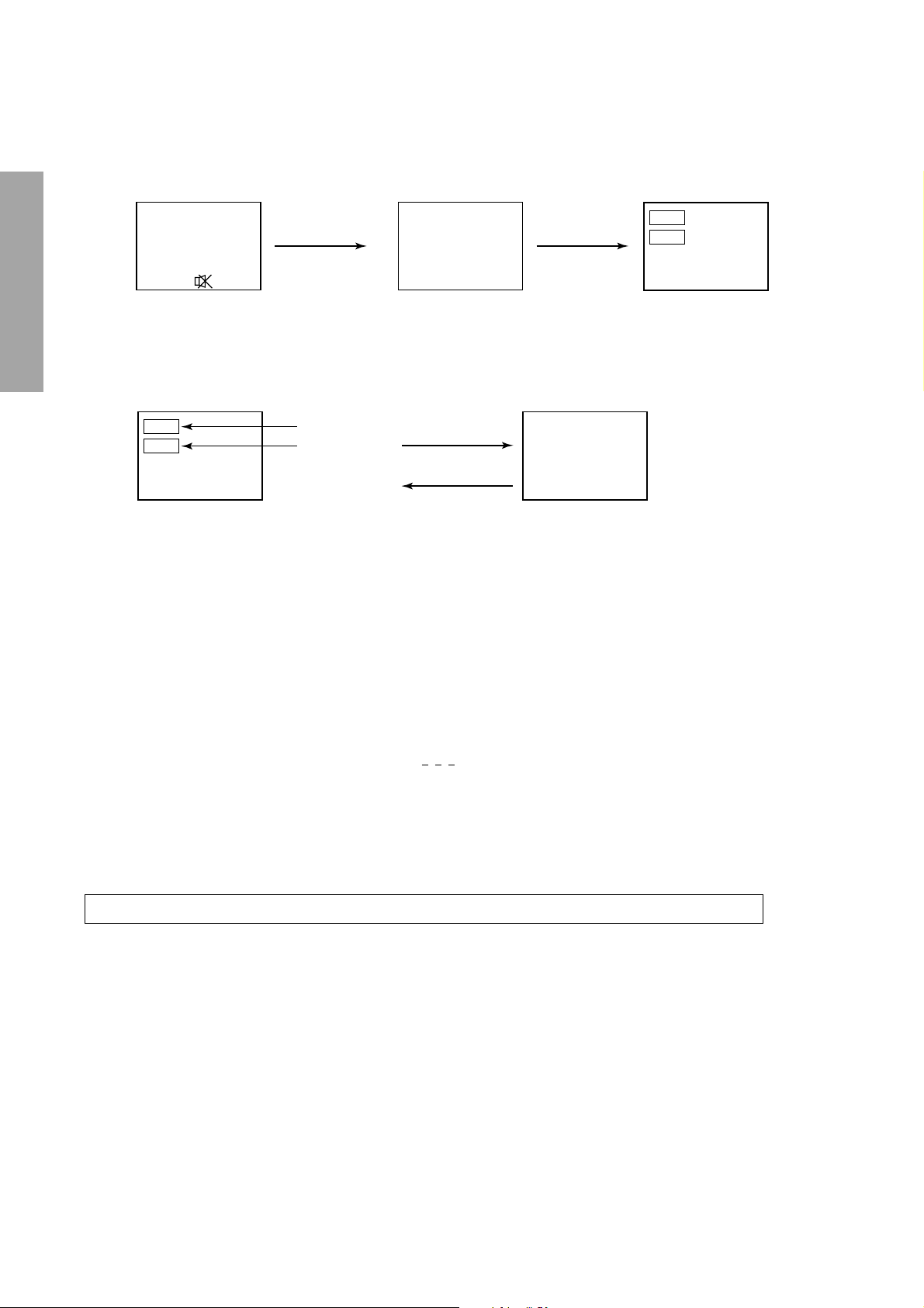
1. ENTERING TO SERVICE MODE
1) Press o button once on
Remote Control.
SERVICE MODE
2) Press o button again to
keep pressing.
3) While pressing the o button,
press MENU button on TV set.
Mute or
2. DISPLAYING THE ADJUSTMENT MENU
GENERAL ADJUSTMENTS
1) Press MENU button on TV.
Adjustment mode
ITEM
DATA
3. KEY FUNCTION IN THE SERVICE MODE
The following key entry during display of adjustment menu provides special functions.
A single horizontal line ON/OFF: INFO button (on Remote) or a button (on TV)
SPECIFIC INFORMATIONS
Test signal selection : a button (on Remote)
Selection of the adjustment items : Channel s/t (on TV or Remote)
Change of the data value : Volume ; +/– (on TV or Remote)
Adjustment menu mode ON/OFF : MENU button (on TV)
Initialization of the memory (QA02) : CALL + Channel button on TV (s)
Reset the count of operating protect
circuit to “00”: CALL + Channel button on TV (t)
“RCUT” selection : 1 button
“GCUT” selection : 2 button
“BCUT” selection : 3 button
“SCNT” selection : 4 button
“COLC” selection : 5 button
“TNTC” selection : 6 button
Self diagnostic display ON/OFF : 9 button
Item
Data
Item
Data
(Service mode display)
Service mode
Press
Press
S
Color thickness correction
note: Displayed differently as shown below, de-
pending on the setting of the receiving color
system.
COLC (PAL/NTSC)
COLS (SECAM)
S
CAUTION : Never try to perform initialization unless you have changed the memory IC.
– 8 –

4. SELECTING THE ADJUSTING ITEMS
1) Every pressing of CHANNEL s button in the service mode changes the adjustment items in the order of table-2.
(t button for reverse order)
Refer to table-2 for preset data of adjustment mode.
(See SETTING & ADJUSTING DATA on page 15)
5. ADJUSTING THE DATA
1) Pressing of VOLUME ; +/– button will change the value of data in the range from 00H to FFH. The variable
range depends on the adjusting item.
6. EXIT FROM SERVICE MODE
1) Pressing POWER button to turn off the TV once.
■ INITIALIZATION OF MEMORY DATA OF QA02
After replacing QA02, the following initialization is required.
1. Enter the service mode, then select any register item.
2. Press and hold the CALL button on the Remote, then press the CHANNEL s button on the TV. The initialization of QA02
has been complated.
3. Check the picture carefully. If necessary, adjust any adjustment item above.
Perform “Auto search Memory” on the owner’s manual.
CAUTION: Never attempt to initialize the data unless QA02 has been replaced.
The signals marked with are not usable to display in the Test signal for some model.
*
GENERAL ADJUSTMENTS
SPECIFIC INFORMATIONS
– 9 –

8. SELF DIAGNOSTIC FUNCTION
1) Press “9” button on Remote Control during display of adjustment menu in the service mode.
The diagnosis will begin to check if interface among IC’s are executed properly.
2) During diagnosis, the following displays are shown.
<SELF CHECK>
23******
POWER : 00
BUS LINE : OK
BUS CONT : OK
BLOCK :
GENERAL ADJUSTMENTS
Part number of microcomputer (QA01)
Operation number of protecting circuit ----“00” is nor-
mal.
When indication is other than “00”, overcurrent apts to
flow, and circuit parts may possibly be damaged.
BUS LINE CHECK ----“OK” is normal.
“SDA1-GND” ------------- SDA-GND short circuit.
“SCL1-GND” -------------- SCL-GND short circuit.
“SCL1-SDA1” ------------- SCL-SDA short circuit.
BUS CONT ----“OK” is normal.
SPECIFIC INFORMATIONS
When indication shows “Q uuu NG”, the device with
the number may possibly be damaged.
BLOCK
UV : TV reception mode
V1 : VIDEO 1 input mode (a1)
V2 : VIDEO 2 input mode (a2)
V3 : VIDEO 3 input mode (a3)
UV V1 V2 V3
QV01
Indicated color of mode now selected : Green and Red
Indicated color of other modes : White
Green : Normal
Red : The microcomputer operates to provide judgement
of no video signal. The red color is still indicated
though the signal is input, failure may exist in input
signal line including QV01.
QV01 : In case of indication green ---Normal
In case of indication red with input signal---Failure may exist in output line including QV01.
The items marked with are not usable to display in the SELF DIAGNOSTIC FUNCTION for some model.
*
– 10 –
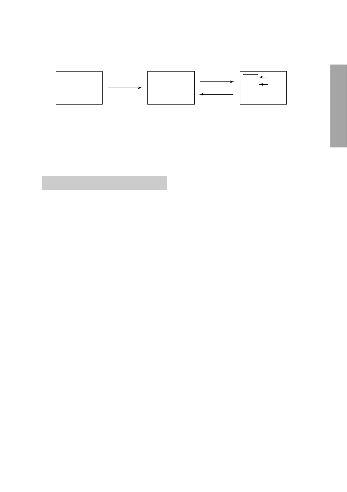
1. ENTERING TO DESIGN MODE
1) Select the Service mode.
DESIGN MODE
2) While pressing o or CALL button on
Remote and press MENU button on TV.
3) Press MENU button on TV.
S D
(Design mode) (Adjustment mode)
When QA02 is initialized, items “OPT0”, “OPT1” and “OPT2” of DESIGN MODE are set to the data of the representative
model of this chassis family.
Therefore, because ON-SCREEN specification remains in the state of the representative of model. This model is required to
reset the data of items “OPT0”, “OPT1” and “OPT2”.
2. SELECTING THE ADJUSTING ITEMS
Every pressing of CHANNEL t button in the design mode changes the adjustment items in the order of table-3.
(s button for reverse order)
Refer to table-3 for data of design mode.
(See SETTING & ADJUSTING DATA on page 15)
3. ADJUSTING THE DATA
Pressing of VOLUME s or t button will change the value of data.
Press
Press
ITEM
DATA
GENERAL ADJUSTMENTS
SPECIFIC INFORMATIONS
– 11 –
 Loading...