

Page 1
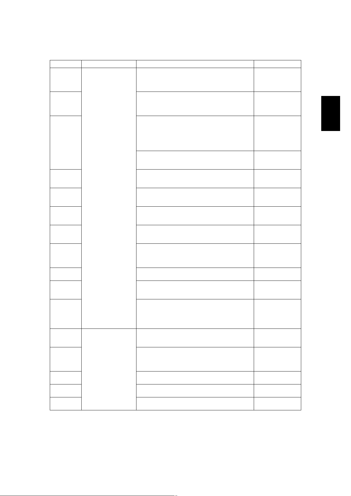
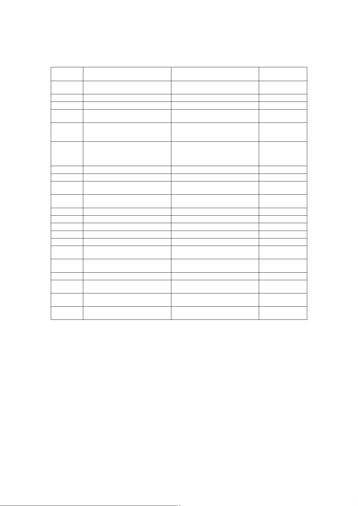
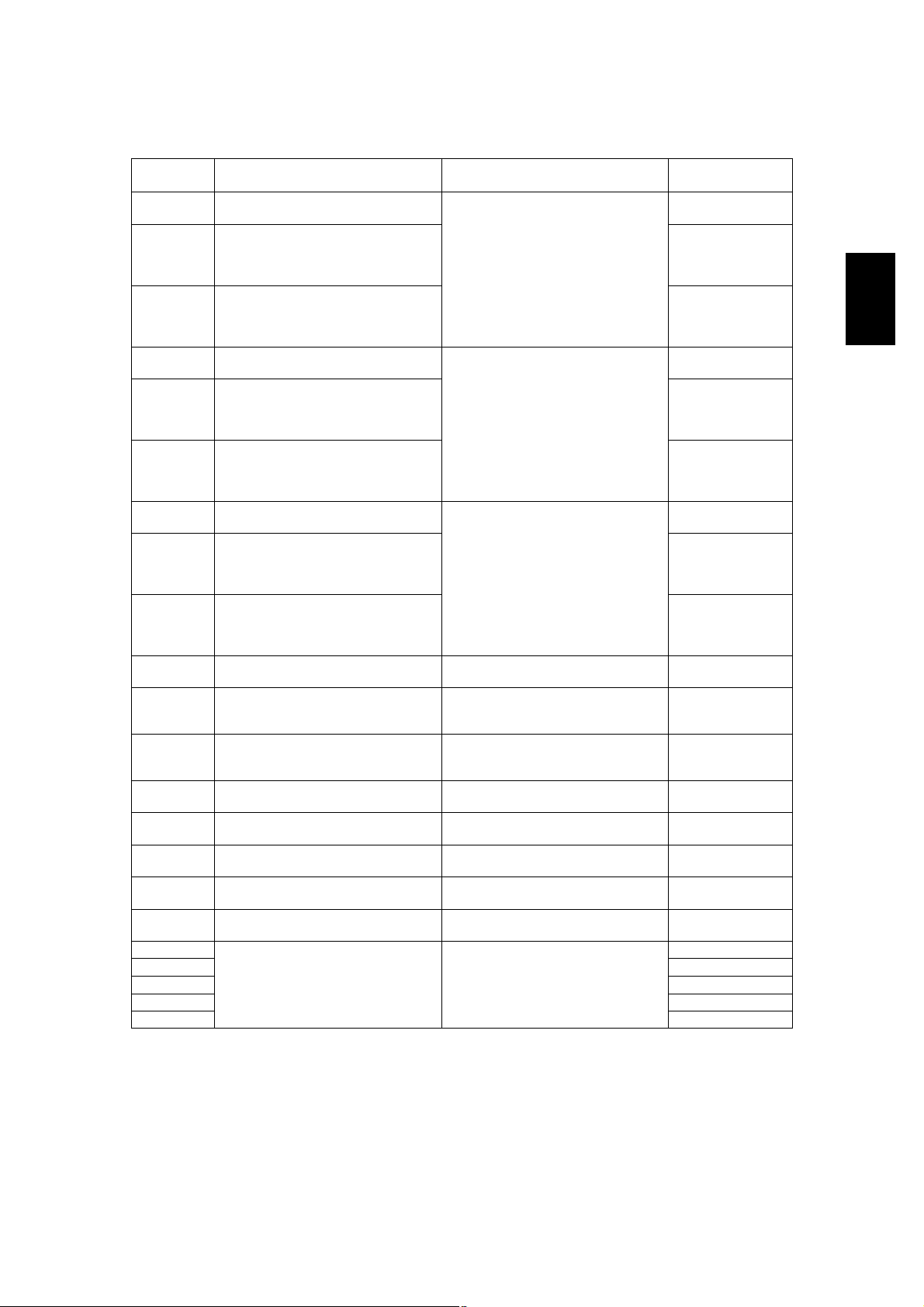
2.ERROR CODE AND SELF-DIAGNOSTIC MODE
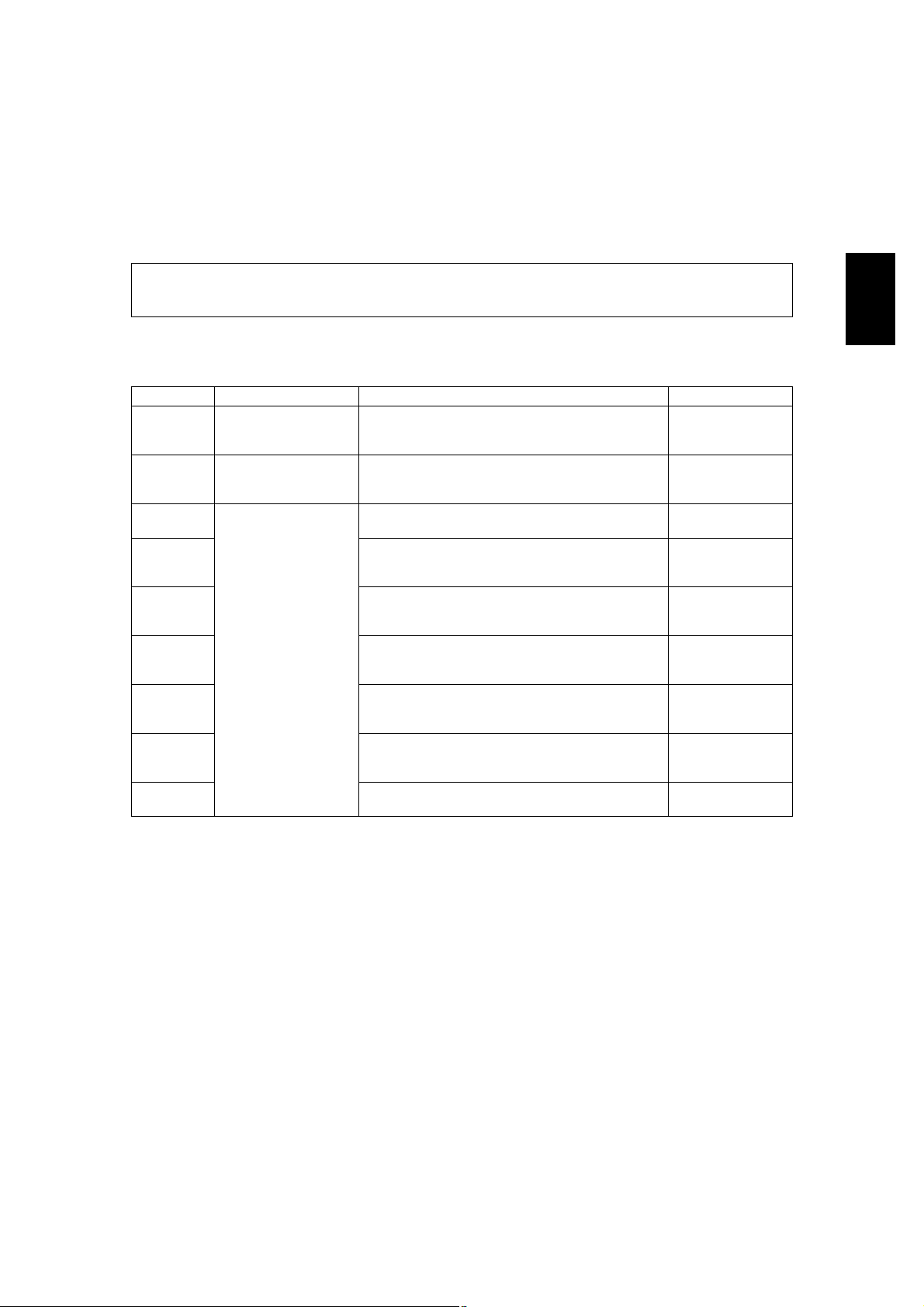
2.1Error Code List
The following error codes is displayed at the upper right of the screen when the CLEAR PAPER! or CALL
SERVICE! symbol is blinking.
2.1.1Jam
Error codeClassificationContentsTroubleshooting
E010Paper exit jamJam not reaching the exit sensor : The paper which
has passed through the fuser unit does not reach
the exit sensor.
E020Paper exit jamStop jam at the exit sensor: The trailing edge of the
paper does not pass the exit sensor after its leading
edge has reached this sensor.
E030Other paper jamPower-ON jam: The paper is remaining on the
paper transport path when power is turned ON.
E061Incorrect paper size setting for upper drawer: The
size of paper in the 1st drawer differs from size setting of the equipment.
E062Incorrect paper size setting for lower drawer: The
size of paper in the 2nd drawer differs from size setting of the equipment.
E063Incorrect paper size setting for PFP upper drawer:
The size of paper in the 3rd drawer differs from size
setting of the equipment.
E064Incorrect paper size setting for PFP lower drawer:
The size of paper in the 4th drawer differs from size
setting of the equipment.
E065Incorrect paper size setting for bypass tray: The
size of paper in the bypass tray differs from size
setting of the equipment.
E090Image data delay jam: Image data to be printed
cannot be prepared.
P. 5-1
P. 5-2
P. 5-18
P. 5-18
P. 5-18
P. 5-18
P. 5-18
P. 5-18
P. 5-19
2
© June 2005 TOSHIBA TECe-STUDIO281c/351c/451c ERROR CODE AND SELF-DIAGNOSTIC MODE
2 - 1
Page 2
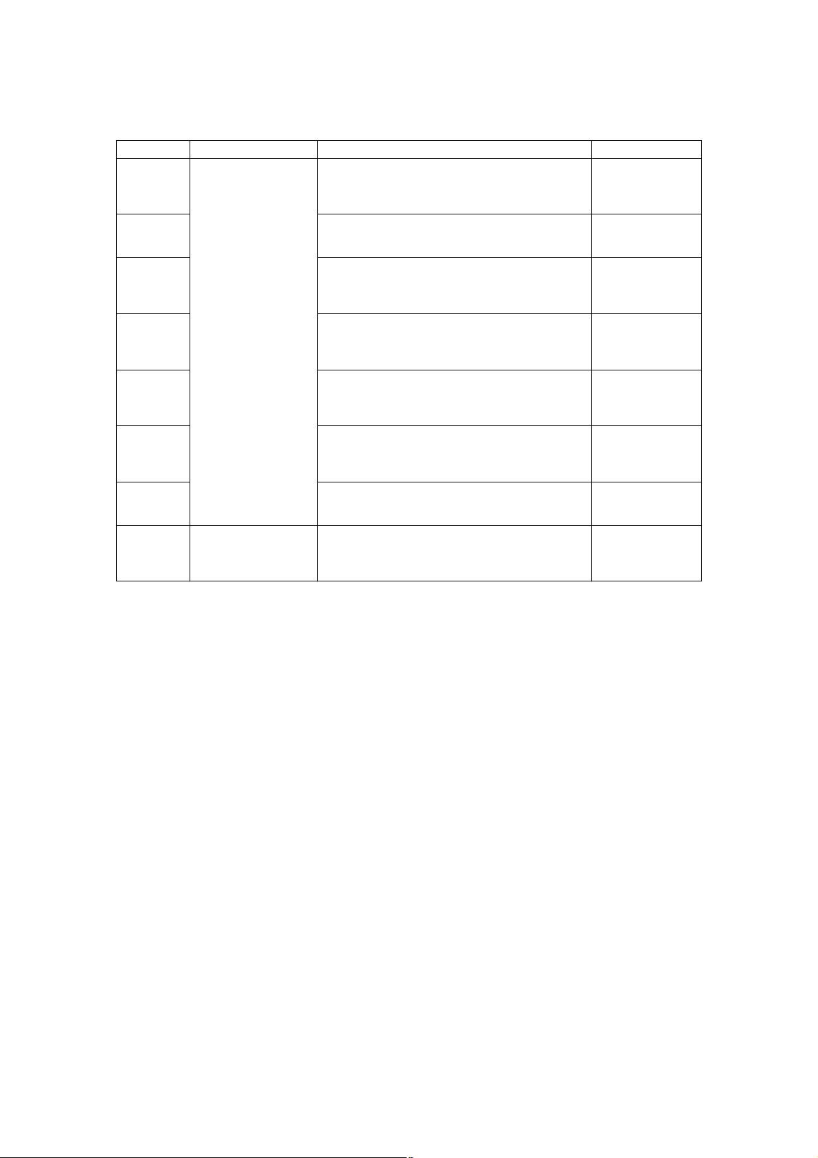
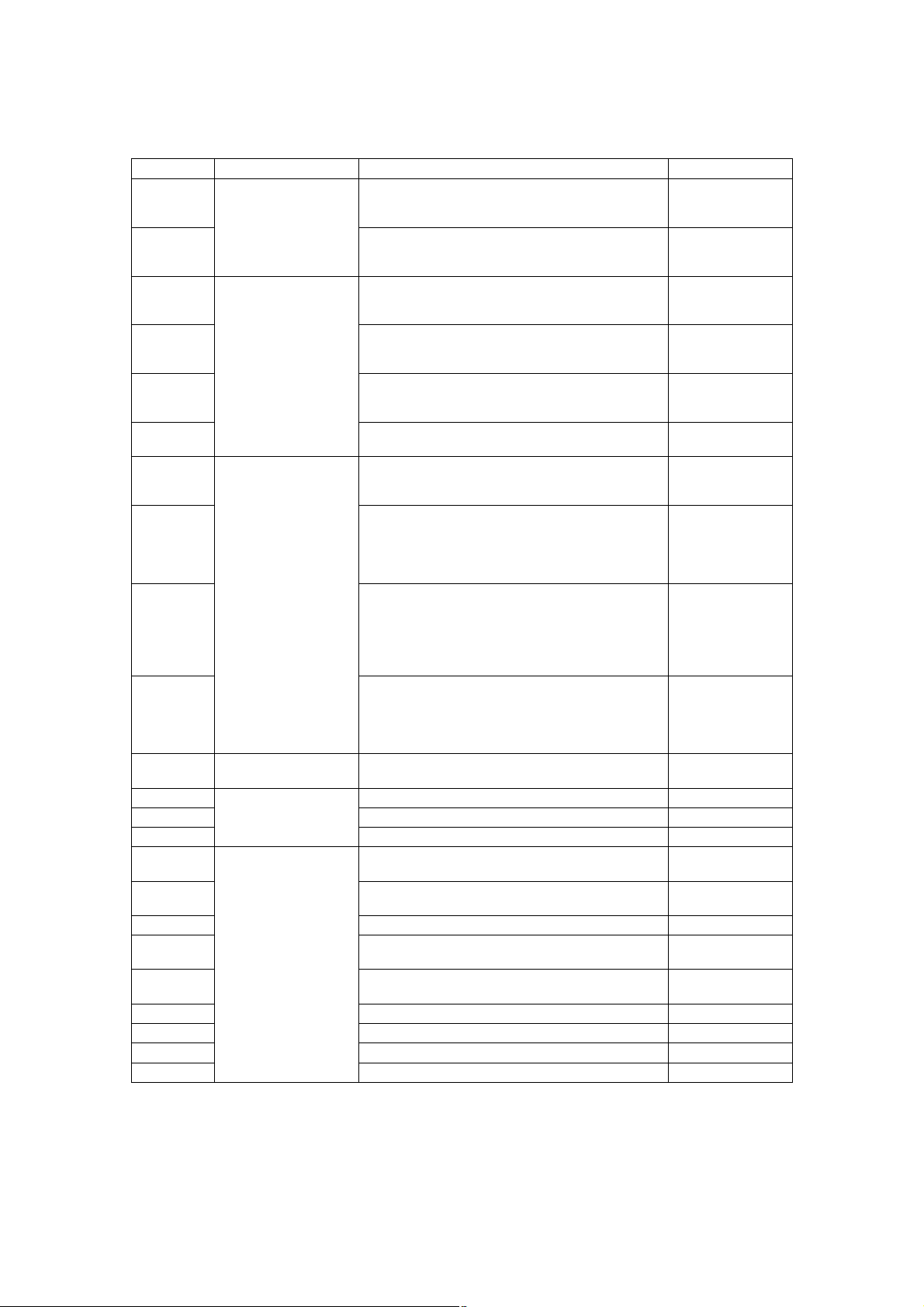
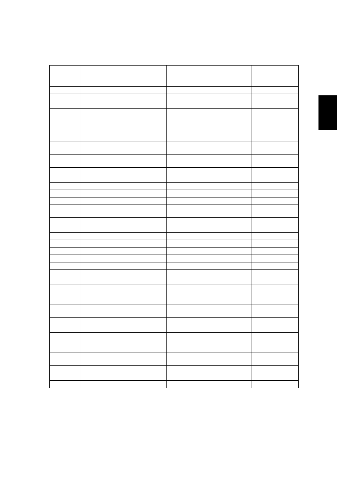
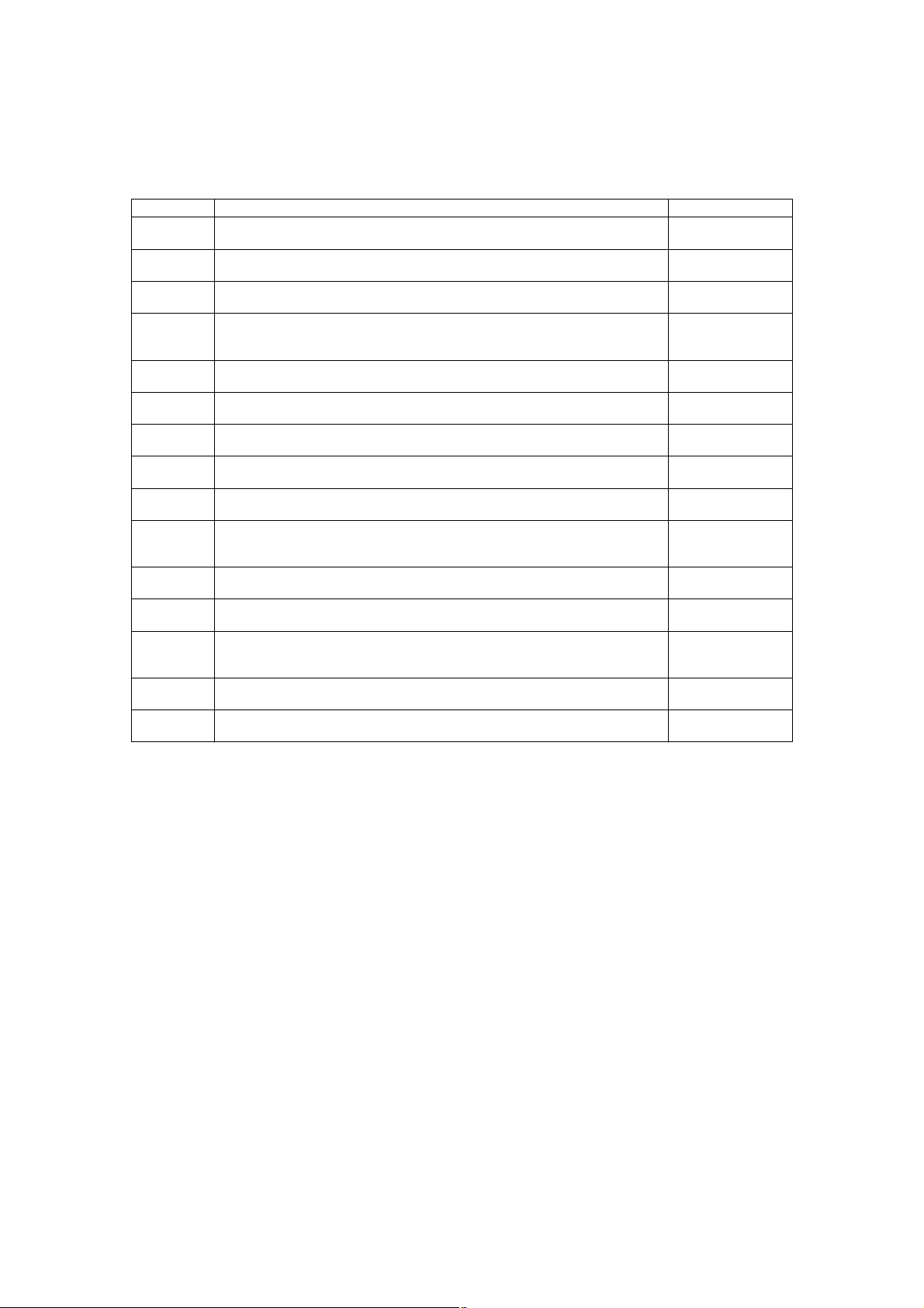
Error codeClassificationContentsTroubleshooting
E110Paper misfeedingADU misfeeding (Paper not reaching the registra-
P. 5-3
tion sensor): The paper which has passed through
ADU does not reach the registration sensor during
duplex printing.
E120Bypass misfeeding (Paper not reaching the regis-
P. 5-4
tration sensor): The paper fed from the bypass tray
does not reach the registration sensor.
E130Upper drawer misfeeding (Paper not reaching the
P. 5-5
upper drawer feed sensor): The paper fed from the
upper drawer does not reach the upper drawer feed
sensor.
E140Lower drawer misfeeding (Paper not reaching the
P. 5-6
lower drawer feed sensor): The paper fed from the
lower drawer does not reach the lower drawer feed
sensor.
E150PFP upper drawer misfeeding (Paper not reaching
P. 5-7
the PFP upper drawer feed sensor): The paper fed
from the PFP upper drawer does not reach the PFP
upper drawer feed sensor.
E160PFP lower drawer misfeeding (Paper not reaching
P. 5-8
the PFP lower drawer feed sensor): The paper fed
from the PFP lower drawer does not reach the PFP
lower drawer feed sensor.
E190LCF misfeeding (Paper not reaching the LCF feed
P. 5-9
sensor): The paper fed from the LCF does not
reach the LCF feed sensor.
E200Paper transport jamUpper drawer transport jam (Paper not reaching the
P. 5-10
registration sensor): The paper does not reach the
registration sensor after it has passed the upper
drawer feed sensor.
e-STUDIO281c/351c/451c ERROR CODE AND SELF-DIAGNOSTIC MODE© June 2005 TOSHIBA TEC
2 - 2
Page 3

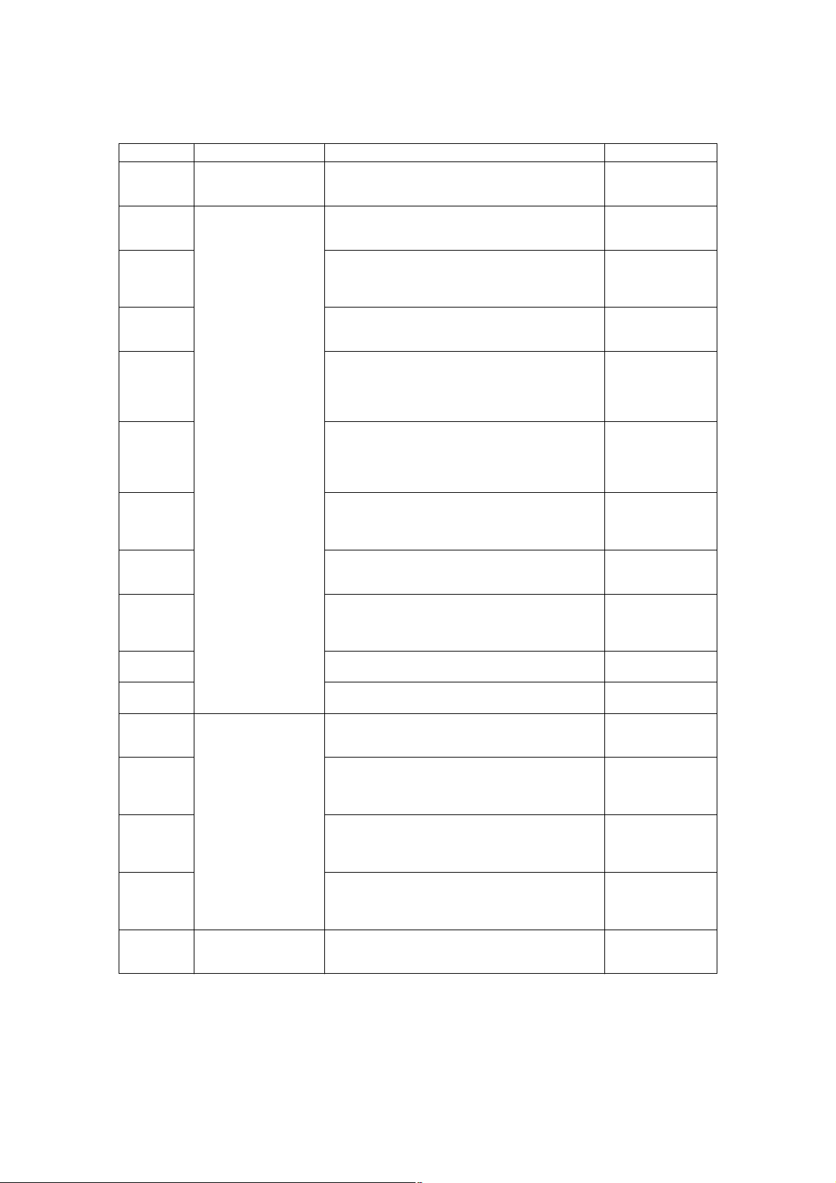
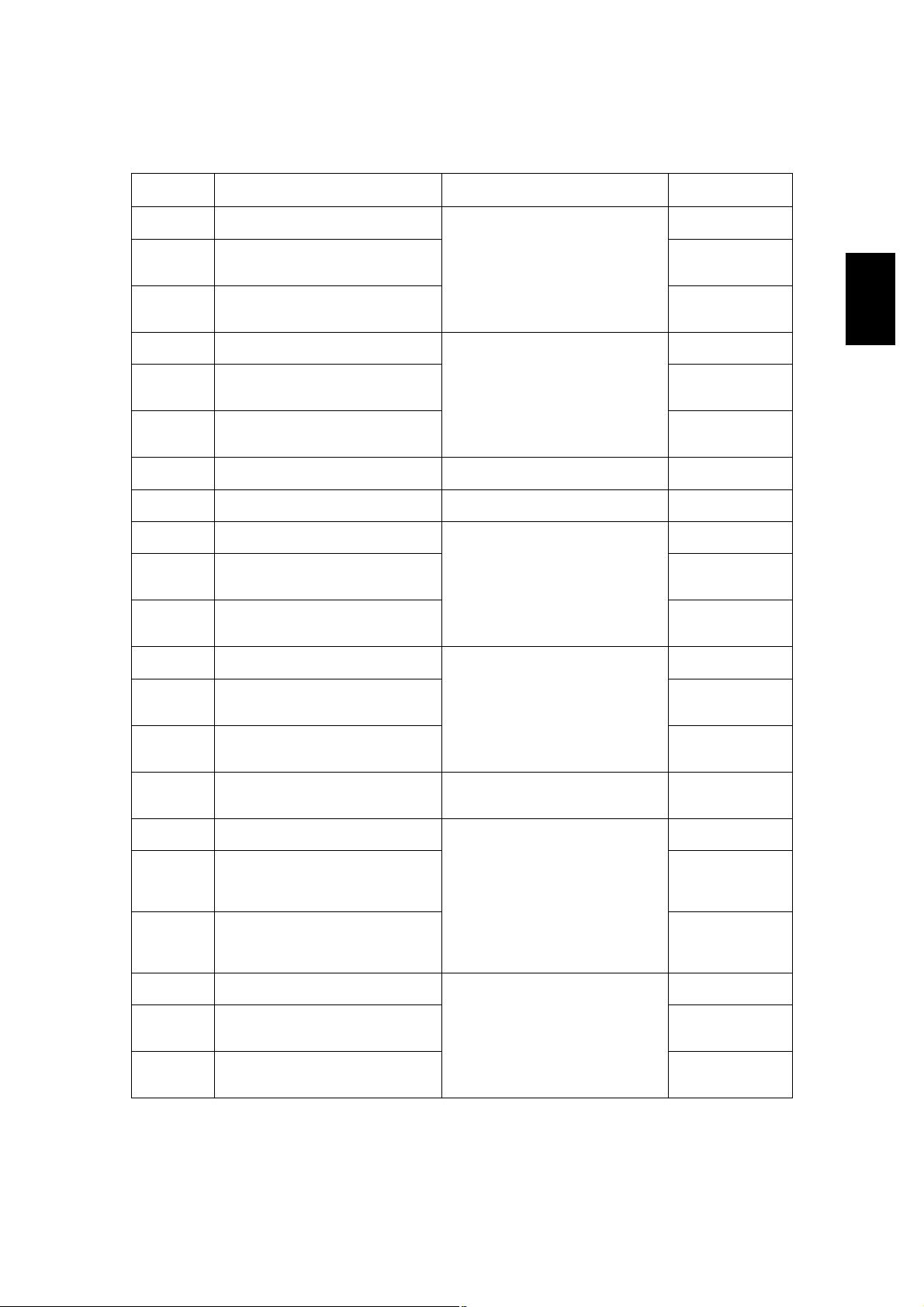
Error codeClassificationContentsTroubleshooting
E210Paper transport jamLower drawer transport jam (Paper not reaching the
E220Lower drawer transport jam (Paper not reaching the
E300PFP upper drawer transport jam (Paper not reach-
E310PFP upper drawer transport jam (Paper not reach-
E320PFP upper drawer transport jam (Paper not reach-
E330PFP lower drawer transport jam (Paper not reach-
E340PFP lower drawer transport jam (Paper not reach-
E350PFP lower drawer transport jam (Paper not reach-
E360PFP lower drawer transport jam (Paper not reach-
E400Cover open jamJam access cover open jam: The jam access cover
E410Front cover open jam: The front cover has opened
E420Cover open jamPFP side cover open jam: The PFP side cover has
E430ADU open jam: The ADU has opened during print-
E440Side cover open jam: The side cover has opened
E450LCF side cover open jam: The LCF side cover has
E480Bridge unit open jam: The bridge unit has opened
E510Paper transport jam
(ADU section)
E520Stop jam in the ADU: The paper does not reach the
registration sensor): The paper does not reach the
registration sensor after it has passed the upper
drawer feed sensor.
upper drawer feed sensor): The paper does not
reach the upper drawer feed sensor after it has
passed the lower drawer feed sensor.
ing the registration sensor): The paper does not
reach the registration sensor after it has passed the
upper drawer feed sensor.
ing the upper drawer feed sensor): The paper does
not reach the upper drawer feed sensor after it has
passed the lower drawer feed sensor.
ing the lower drawer feed sensor): The paper does
not reach the lower drawer feed sensor after it has
passed the PFP upper drawer feed sensor.
ing the PFP upper drawer feed sensor): The paper
does not reach the PFP upper drawer feed sensor
after it has passed the PFP lower drawer feed sensor.
has opened during printing.
during printing.
opened during printing.
ing.
during printing.
opened during printing.
during printing.
Jam not reaching the ADU entrance sensor: The
paper does not reach the ADU entrance sensor
after it is switchbacked in the exit section.
ADU exit sensor after it has passed the ADU
entrance sensor.
P. 5-10
P. 5-11
P. 5-10
P. 5-11
P. 5-12
P. 5-10
P. 5-11
P. 5-12
P. 5-13
P. 5-20
P. 5-20
P. 5-21
P. 5-21
P. 5-22
P. 5-22
P. 5-23
P. 5-14
P. 5-15
2
© June 2005 TOSHIBA TECe-STUDIO281c/351c/451c ERROR CODE AND SELF-DIAGNOSTIC MODE
2 - 3
Page 4
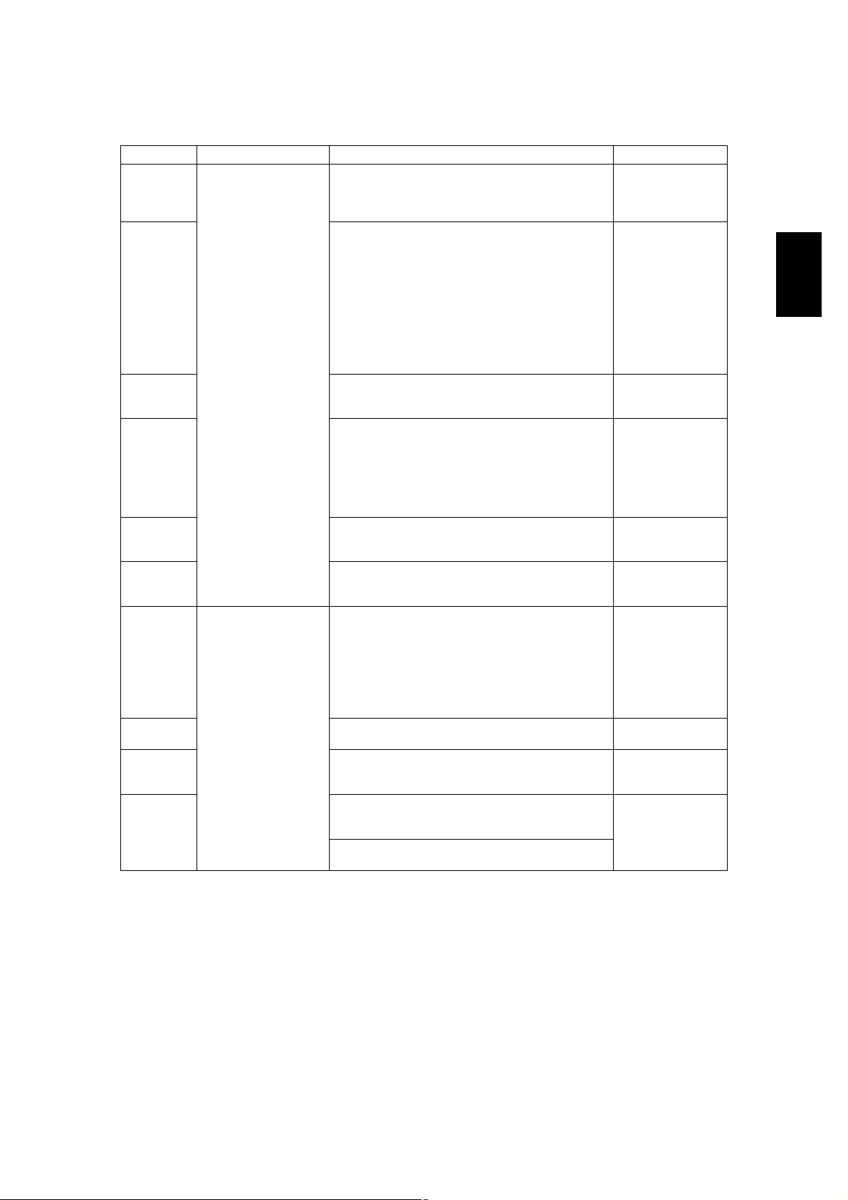
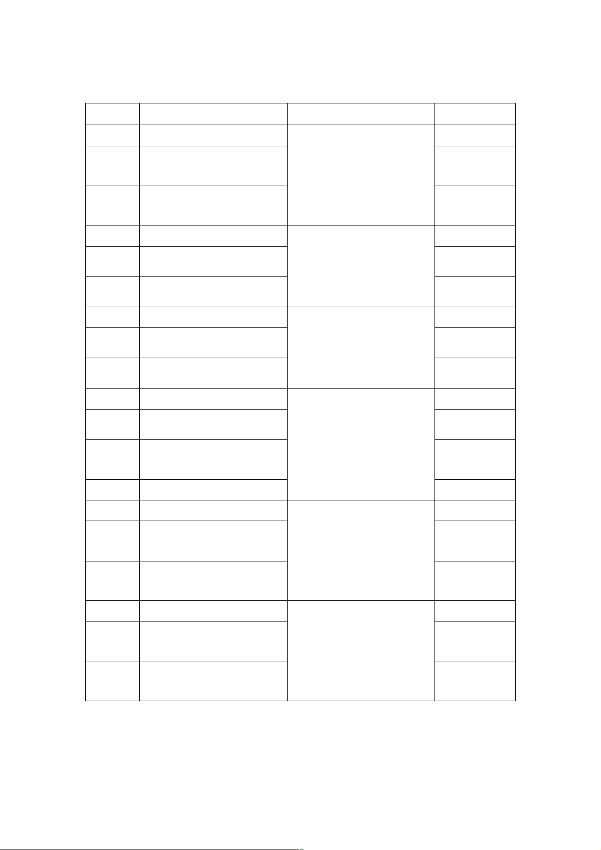
Error codeClassificationContentsTroubleshooting
E550Other paper jamPaper remaining jam on the transport path: The
P. 5-19
paper is remaining on the transport path when printing is finished (caused by a multiple paper feeding).
E712RADF jamJam not reaching the original registration sensor:
P. 5-24
The original fed from the original feeding tray does
not reach the original registration sensor.
E713Cover open jam in the read ready status: Jam
P. 5-24
caused by opening of the RADF jam access cover
or front cover while the RADF is waiting for the
scanning start signal from the equipment.
E714Feed signal reception jam: The feed signal is
P. 5-25
received even no original exists on the original
feeding tray.
E721Jam not reaching the read sensor: The original
P. 5-25
does not reach the read sensor after it has passed
the registration sensor (when scanning obverse
side) or the reverse sensor (when scanning reverse
side).
E722Jam not reaching the original exit/reverse sensor
P. 5-26
(during scanning): The original which passed the
read sensor does not reach the original exit/reverse
sensor when it is transported from the scanning
section to exit section.
E724Stop jam at the original registration sensor: The
P. 5-26
trailing edge of the original does not pass the original registration sensor after its leading edge has
reached this sensor.
E725Stop jam at the read sensor: The trailing edge of the
P. 5-27
original does not pass the read sensor after its leading edge has reached this sensor.
E731Stop jam at the original exit/reverse sensor: The
P. 5-27
trailing edge of the original does not pass the original exit/reverse sensor after its leading edge has
reached this sensor.
E860RADF jam access cover open: The RADF jam
P. 5-27
access cover has opened during RADF operation.
E870RADF open jam: RADF has opened during RADF
P. 5-28
operation.
E910Finisher jam
(Bridge unit)
Jam at the bridge unit transport sensor 1: The
paper does not reach the bridge unit transport sen-
P. 5-29
sor 1 after it has passed the exit sensor.
E920Stop jam at the bridge unit transport sensor 1: The
P. 5-29
trailing edge of the paper does not pass the bridge
unit transport sensor 1 after its leading edge has
reached the sensor.
E930Jam at the bridge unit transport sensor 2: The trail-
P. 5-29
ing edge of the paper does not reach the bridge unit
transport sensor 2 after its leading edge has
reached the bridge unit transport sensor 1.
E940Stop jam at the bridge unit transport sensor 2: The
P. 5-29
trailing edge of the paper does not pass the bridge
unit transport sensor 2 after its leading edge has
reached the bridge unit transport sensor 2.
E9F0Finisher jam
(Punch unit)
Punching jam: Punching is not performed properly.
[MJ-1023/1024 (when MJ-6004 is installed)]
P. 5-46
[MJ-1101 (when MJ-6101 is installed)]
e-STUDIO281c/351c/451c ERROR CODE AND SELF-DIAGNOSTIC MODE© June 2005 TOSHIBA TEC
2 - 4
06/08
Page 5
Error codeClassificationContentsTroubleshooting
EA10Finisher jam
(Finisher section)
Paper transport delay jam: The paper which has
passed the bridge
P. 5-30
unit does not reach the inlet sensor. [MJ-1022/
1023/1024/1101]
EA20 Paper transport stop jam:
P. 5-32
(1) The paper does not pass through the inlet sen-
sor.
[MJ-1022/1023/1024]
(2) The paper has passed through the inlet sensor
but does not reach or pass the feed path sensor
or processing tray sensor.
[MJ-1023/1024]
(3)The paper which has passed through the inlet
sensor does not reach the transport sensor.
[MJ-1101]
EA21Paper size error jam: Paper does not reach the sen-
P. 5-33
sor because the paper is shorter than spec. [MJ1101]
EA30Power-ON jam:
P. 5-34
(1) Paper exists at the inlet sensor when power is
turned ON.
[MJ-1022/1023/1024]
(2) Paper exists at the feed path sensor or pro-
cessing tray sensor when power is turned ON.
[MJ-1023/1024]
EA31Transport path paper remaining jam: The paper
P. 5-35
which has passed through the inlet sensor does not
reach the transport sensor. [MJ-1101]
EA32Exit paper remaining jam: The paper is remaining
P. 5-35
on the finishing tray when the power is turned ON.
[MJ-1101]
EA40Finisher jam
(Finisher section)
Door open jam:
1)The finisher has been released from the equip-
P. 5-36
ment during printing. [MJ-1022]
2)The upper/front cover of the finisher section or
the upper/ front door of the puncher section has
opened during printing. [MJ-1023/1024]
3)The front cover or stationary tray cover is
opened during paper transport. [MJ-1101]
EA50Stapling jam: Stapling is not performed properly.
P. 5-38
[MJ-1022/1023/1024/1101]
EA60Early arrival jam: The inlet sensor detects the paper
P. 5-40
earlier than a specified timing. [MJ-1022/1023/
1024/1101]
EA70Stack delivery jam: It cannot deliver the stack of
P. 5-41
paper on the intermediary process tray to the stack
tray. [MJ-1022]
Stack exit belt home position error: The stack exit
belt is not at the home position. [MJ-1101]
2
© June 2005 TOSHIBA TECe-STUDIO281c/351c/451c ERROR CODE AND SELF-DIAGNOSTIC MODE
2 - 5
06/08
Page 6
Error codeClassificationContentsTroubleshooting
EA80Finisher jam
(Saddle stitcher sec-
EA90Door open jam: The delivery cover or inlet cover
tion)
Stapling jam: Stapling is not performed properly.
[MJ-1024]
P. 5-43
P. 5-43
has opened dur-ing printing [MJ-1024].
EAA0Power-ON jam: Paper exists at No.1 paper sensor,
P. 5-44
No. 2 paper sensor, No.3 paper sensor, vertical
path paper sensor or delivery sensor when power is
turned ON. [MJ-1024]
EAB0Transport stop jam: The paper which passed
P. 5-44
through the inlet sensor does not reach or pass
No.1 paper sensor, No. 2 paper sensor, No.3 paper
sensor or delivery sensor. [MJ-1024]
EAC0Transport delay jam: The paper which has reached
P. 5-45
the inlet sensor does not pass through the inlet sensor. [MJ-1024]
EAD0Other paper jamPrint end command time-out jam: The printing has
P. 5-47
not finished normally because of the communication error between the SYS board and LGC board
at the end of printing.
EAE0Finisher jamReceiving time time-out jam: The printing has been
P. 5-47
interrupted because of the communication error
between the equipment and finisher when the
paper is transported from the equipment to the finisher.
EAF0Finisher jam
(Finisher section)
Stack return jam: It cannot load the paper which
passed through the delivery roller on the intermedi-
P. 5-42
ary process tray. [MJ-1022]
EB30Finisher jamReady time time-out jam: The equipment judges
P. 5-47
that the paper transport to the finisher is disabled
because of the communication error between the
equipment and finisher at the start of printing.
EB50Paper transport jamPaper remaining on the transport path: The multiple
P. 5-16
feeding of preceding paper caused the misfeeding
of upcoming paper.
EB60Paper remaining on the transport path: The multiple
P. 5-17
feeding of preceding paper caused the misfeeding
of upcoming paper (redetection after no jam is
detected at [EB50]).
ED10Finisher jamSideways adjustment motor (M2) home position
P. 5-48
detection error: The Sideways adjustment motor is
not at the home position. [MJ-1101 (when MJ-6101
is installed)]
ED11Skew adjustment motor (M1) home position detec-
P. 5-48
tion abnormality: The Skew adjustment motor is not
at the home position. [MJ-1101 (when MJ-6101 is
installed)]
ED12Shutter home position error: The shutter is not at
P. 5-49
the home position. [MJ-1101]
ED13Front alignment plate home position error: The front
P. 5-49
alignment plate is not at the home position. [MJ1101]
ED14Rear alignment plate home position error: The rear
P. 5-50
alignment plate is not at the home position. [MJ1101]
ED15Paddle home position error: The paddle is not at the
P. 5-50
home position. [MJ-1101]
ED16Buffer tray home position error: The buffer tray is
P. 5-51
not at the home position. [MJ-1101]
e-STUDIO281c/351c/451c ERROR CODE AND SELF-DIAGNOSTIC MODE© June 2005 TOSHIBA TEC
2 - 6
06/08
Page 7

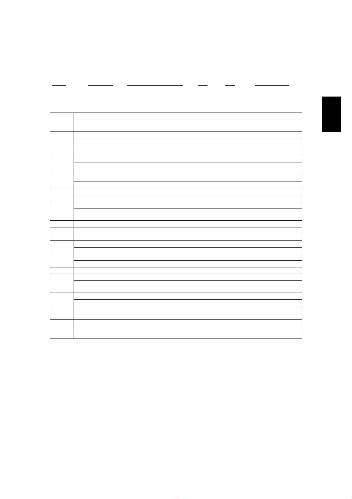
2.1.2Service call
Error codeClassificationContentsTroubleshooting
C010Drive system related
service call
C020Developer motor abnormality: The developer motor
C030Transport motor abnormality: The transport motor is
C040Paper feeding system
related service call
C130Upper drawer tray abnormality: The upper drawer
C140Lower drawer tray abnormality: The lower drawer
C150PFP upper drawer tray abnormality: The PFP upper
C160PFP lower drawer tray abnormality: The PFP lower
C180LCF tray-up motor abnormality: The LCF tray-up
C1A0LCF end fence motor abnormality: The LCF end
C1B0LCF transport motor abnormality: The LCF trans-
C260Scanning system
related service call
C270Carriage home position sensor not turning OFF
C280Carriage home position sensor not turning ON
C360Copy process related
service call
Main motor abnormality: The main motor is not
rotating normally.
is not rotating normally.
not rotating normally.
PFP motor abnormality: The PFP motor is not rotating normally. (the case that paper can be fed from
any drawer except the PFP)
tray-up motor is not rotating or the upper drawer
tray is not moving normally. (the case that paper
can be fed from any drawer except the upper
drawer)
tray-up motor is not rotating or the lower drawer tray
is not moving normally. (the case that paper can be
fed from any drawer except the lower drawer)
drawer tray-up motor is not rotating or the PFP
upper drawer tray is not moving normally. (the case
that paper can be fed from any drawer except the
PFP upper drawer)
drawer tray-up motor is not rotating or the PFP
lower drawer tray is not moving normally. (the case
that paper can be fed from any drawer except the
PFP lower drawer)
motor is not rotating or the LCF tray is not moving
normally. (the case that paper can be fed from any
drawer except the LCF)
fence motor is not rotating or the LCF end fence is
not moving normally. (the case that paper can be
fed from any drawer except the LCF)
port motor is not rotating normally. (the case that
paper can be fed from any drawer except the LCF)
Peak detection error: Lighting of the exposure lamp
(white reference) is not detected when power is
turned ON.
within a specified period of time: The carriage does
not shift from its home position in a specified time.
within a specified period of time: The carriage does
not reach to its home position in a specified period
of time.
Charger cleaner motor abnormality: Charger
cleaner motor is not rotating or wire cleaner is not
moving normally.
P. 5-52
P. 5-52
P. 5-52
P. 5-53
P. 5-54
P. 5-54
P. 5-55
P. 5-55
P. 5-56
P. 5-57
P. 5-58
P. 5-59
P. 5-59
P. 5-59
P. 5-89
2
© June 2005 TOSHIBA TECe-STUDIO281c/351c/451c ERROR CODE AND SELF-DIAGNOSTIC MODE
2 - 7
Page 8
Error codeClassificationContentsTroubleshooting
C411Fuser unit related ser-
vice call
Thermistor or heater abnormality at power-ON:
Abnormality of the thermistor is detected when
P. 5-60
power is turned ON or the temperature of the fuser
roller does not rise in a specified period of time after
power is turned ON.
C412Thermistor/heater abnormality at power-ON: Ther-
P. 5-60
mistor abnormality is detected at power-ON or the
fuser roller temperature does not rise within a specified period of time after power-ON.
C443Heater abnormality after abnormality judgment (not
P. 5-61
reaching to intermediate temperature)
C445Heater abnormality after abnormality judgment
P. 5-61
(pre-running end temperature abnormality)
C446Heater abnormality after abnormality judgment
P. 5-61
(pre-running end temperature abnormality)
C447Heater abnormality after abnormality judgment
P. 5-61
(temperature abnormality at ready status)
C449Heater abnormality after abnormality judgment
P. 5-61
(overheating)
C471IH power voltage abnormality or IH initial abnormal-
P. 5-61
ity
(IH board initial abnormality)
C472IH power voltage abnormality (power supply abnor-
P. 5-61
mality)
C475IH power voltage abnormality (power supply abnor-
P. 5-61
mality when door is opened)
C480Overheating of IGBT: The temperature of the IGBT
P. 5-61
rises abnormally.
C490IH control circuit or IH coil abnormality: Abnormality
P. 5-62
is detected in IH control circuit or IH coil is broken/
shorted.
C4B0Fuser unit counter abnormalityP. 5-62
C550Optional communica-
tion related service call
C570Communication error between Engine-CPU and
RADF I/F error: Communication error has occurred
between the RADF and the scanner.
P. 5-63
P. 5-63
IPC board
C580Communication error between IPC board and fin-
P. 5-63
isher
C900Circuit related service
call
Connection error between SYS board and LGC
board
P. 5-64
C940Engine-CPU abnormalityP. 5-64
C950LGC board memory abnormalityP. 5-64
C960Connection error between LGC board and DRV
P. 5-64
board, ID abnormality
C970Process related ser-
vice call
C9E0Circuit related service
call
CA10Laser optical unit
related service call
CA20H-Sync detection error: H-Sync signal detection PC
High-voltage transformer abnormality: Leakage of
the main charger is detected.
Connection error between SLG board and SYS
board, ID abnormality
Polygonal motor abnormality: The polygonal motor
is not rotating normally.
P. 5-89
P. 5-65
P. 5-66
P. 5-66
board cannot detect laser beams.
e-STUDIO281c/351c/451c ERROR CODE AND SELF-DIAGNOSTIC MODE© June 2005 TOSHIBA TEC
2 - 8
Page 9
Error codeClassificationContentsTroubleshooting
CB10Finisher related
service call
CB11Buffer tray guide motor abnormality: The buffer tray
Entrance motor abnormality: The entrance motor is
not rotating normally. [MJ-1101]
P. 5-67
P. 5-67
guide motor is not rotating or the buffer tray guide is
not moving normally. [MJ-1101]
CB12Buffer roller drive motor abnormality: The buffer
P. 5-67
roller drive motor is not rotating or the buffer roller is
not moving normally. [MJ-1101]
CB20Delivery motor abnormality: Delivery motor or deliv-
P. 5-68
ery roller is not rotating normally. [MJ-1022]
CB30Tray 1/Tray 2 shift motor abnormality: Tray 1/Tray 2
P. 5-68
shift motor is not rotating or delivery tray is not moving normally. [MJ-1023/1024]
Movable tray shift motor abnormality: The movable
P. 5-68
tray shift motor is not rotating or the movable tray is
not moving normally. [MJ-1101]
CB31Movable tray paper-full detection error: The actua-
P. 5-69
tor of the movable tray paper-full detection sensor
does not move smoothly. [MJ-1101]
CB40Rear aligning plate motor abnormality: Rear align-
P. 5-69
ing plate motor is not rotating or aligning plate is not
moving normally. [MJ-1023/1024]
Front alignment motor abnormality: The front align-
P. 5-69
ment motor is not rotating or the front alignment
plate is not moving normally. [MJ-1101]
CB50Staple motor abnormality: Staple motor is not rotat-
P. 5-70
ing or stapler is not moving normally. [MJ-1022/
1023/1024]
Stapler home position error: The stapler home posi-
P. 5-70
tion sensor does not work. [MJ-1101]
CB51Stapler shift home position error: The stapler is not
P. 5-70
at the home position. [MJ-1101]
CB60Stapler shift motor abnormality: Stapler shift motor
P. 5-71
is not rotating or staple unit is not moving normally.
[MJ-1023/1024/1101]
CB80Backup RAM data abnormality:
P. 5-71
1)Abnormality of checksum value on finisher con-
troller PC board is detected when the power is
turned ON. [MJ-1023/1024]
2)Abnormality of checksum value on punch con-
troller PC board is detected when the power is
turned ON. [MJ-1023/1024 (when MJ-6004 is
installed)]
RAM abnormality: Abnormality of checksum value
P. 5-71
on finisher controller PC board is detected when the
power is turned on. [MJ-1101]
CB81Flash ROM abnormality: Abnormality of checksum
P. 5-72
value on finisher controller PC board is detected
when the power is turned on. [MJ-1101]
CB90Paper pushing plate motor abnormality: Paper
P. 5-72
pushing plate motor is not rotating or paper pushing
plate is not moving normally. [MJ-1024]
CBA0Stitch motor (front) abnormality: Stitch motor (front)
P. 5-72
is not rotating or rotary cam is not moving normally.
[MJ-1024]
CBB0Stitch motor (rear) abnormality: Stitch motor (rear)
P. 5-72
is not rotating or rotary cam is not moving normally.
[MJ-1024]
2
© June 2005 TOSHIBA TECe-STUDIO281c/351c/451c ERROR CODE AND SELF-DIAGNOSTIC MODE
2 - 9
06/08
Page 10
Error codeClassificationContentsTroubleshooting
CBC0Finisher related
service call
Alignment motor abnormality: Alignment motor is
not rotating or aligning plate is not moving normally.
P. 5-72
[MJ-1024]
CBD0Guide motor abnormality: Guide motor is not rotat-
P. 5-73
ing or guide is not moving normally. [MJ-1024]
CBE0Paper folding motor abnormality: Paper folding
P. 5-73
motor or paper folding roller is not rotating normally.
[MJ-1024]
CBF0Paper positioning plate motor abnormality: Paper
P. 5-73
positioning plate motor is not rotating or paper positioning plate is not moving normally. [MJ-1024]
CC00Sensor connector abnormality: Connector of guide
P. 5-74
home position sensor, paper pushing plate home
position sensor or paper pushing plate top position
sensor is disconnected. [MJ-1024]
CC10Micro switch abnormality: With all covers closed,
P. 5-74
inlet door switch, delivery door switch or front cover
switch is open. [MJ-1024]
CC20Communication error between finisher and saddle
P. 5-74
stitcher: Communication error between finisher controller PC board and saddle stitcher controller board
[MJ-1023/1024]
CC30Stack processing motor abnormality: The stack pro-
P. 5-75
cessing motor is not rotating or the stack delivery
belt is not moving normally. [MJ-1022]
Stack transport motor abnormality: The stack trans-
P. 5-76
port motor is not rotating or the stack transport belt
is not moving normally. [MJ-1101]
CC31Transport motor abnormality: The transport motor is
P. 5-76
not rotating or the stack transport roller -1 and -2 is
not rotating normally. [MJ-1101]
CC40Swing motor abnormality: Swing motor is not rotat-
P. 5-76
ing or swing unit is not moving normally. [MJ-1023/
1024]
CC41Paper holder cam home position abnormality: The
P. 5-77
paper holder cam is not at the home position. [MJ1101]
CC50Horizontal registration motor abnormality: Horizon-
P. 5-77
tal registration motor is not rotating or puncher is
not shifting normally. [MJ-1023/1024 (when MJ6004 is installed)]
CC51Sideways adjustment motor (M2) abnormality:
P. 5-77
Sideways adjustment motor is not rotating or
puncher is not shifting normally. [MJ-1101 (when
MJ-6101 is installed)
CC52Skew adjustment motor (M1) abnormality: Skew
P. 5-78
adjustment motor is not rotating or puncher is not
shifting normally. [MJ-1101 (when MJ-6101 is
installed)]
CC60Punch motor abnormality: Punch motor is not rotat-
P. 5-78
ing or puncher is not shifting normally. [MJ-1023/
1024 (when MJ-6004 is installed)]
CC61Punch motor (M3) home position detection error:
P. 5-79
Punch motor is not rotating or puncher is not shifting normally. [MJ-1101 (when MJ-6101 is installed)]
e-STUDIO281c/351c/451c ERROR CODE AND SELF-DIAGNOSTIC MODE© June 2005 TOSHIBA TEC
2 - 10
06/08
Page 11
Error codeClassificationContentsTroubleshooting
CC71Finisher related
service call
Punch ROM checksum error: Abnormality of checksum value on Hole punch controller PC board is
P. 5-79
detected when the power is turned on. [MJ-1101
(when MJ-6101 is installed)]
CC72Punch RAM read/write error: Abnormality of check-
P. 5-79
sum value on Hole punch controller PC board is
detected when the power is turned on. [MJ-1101
(when MJ-6101 is installed)]
CC80Front alignment motor abnormality: Front alignment
P. 5-80
motor is not rotating or front aligning plate is not
moving normally. [MJ-1022]
Front aligning plate motor abnormality: Front aligning plate motor is not rotating or aligning plate is not
moving normally. [MJ-1023/1024]
Rear alignment motor abnormality: The rear align-
P. 5-80
ment motor is not rotating or the rear alignment
plate is not moving normally. [MJ-1101]
CC90Upper stack tray lift motor abnormality: The upper
P. 5-81
stack tray lift motor is not rotating or the upper stack
tray is not moving normally. [MJ-1022]
CCA0Lower stack tray lift motor abnormality: The lower
P. 5-82
stack tray lift motor is not rotating or the lower stack
tray is not moving normally. [MJ-1022]
CCB0Rear jogging motor abnormality: The rear jogging
P. 5-82
motor is not rotating or the rear jogging plate is not
moving normally. [MJ-1022]
CCD0Stack ejection motor abnormality: Stack ejection
P. 5-83
motor or stack ejection roller is not rotating normally. [MJ-1023/1024]
CCE0Paper trailing edge assist motor abnormality: Paper
P. 5-83
trailing edge assist motor is not rotating or paper
trailing edge assist is not moving normally. [MJ1023/1024]
CCF0Gear changing motor abnormality: Gear changing
P. 5-83
motor is not rotating normally. [MJ-1023/1024]
CDE0Paddle motor abnormality: The paddle motor is not
P. 5-84
rotating or the paddle is not rotating normally. [MJ1101]
CE00Communication error between finisher and punch
P. 5-84
unit: Communication error between finisher controller PC board and punch controller PC board [MJ1023/1024 (when MJ-6004 is installed)]
[MJ-1101 (when MJ-6101 is installed)]
CE10Image control related
service call
Image quality sensor abnormality (OFF level): The
output value of this sensor is out of a specified
P. 5-85
range when sensor light source is OFF.
CE20Image quality sensor abnormality (no pattern level):
P. 5-86
The output value of this sensor is out of a specified
range when the image quality control test pattern is
not formed.
CE40Image quality control test pattern abnormality: The
P. 5-87
test pattern is not formed normally.
CE50Temperature/humidity sensor abnormality: The out-
P. 5-88
put value of this sensor is out of a specified range.
CE90Drum thermistor abnormality: The output value of
P. 5-88
the drum thermistor is out of a specified range.
2
© June 2005 TOSHIBA TECe-STUDIO281c/351c/451c ERROR CODE AND SELF-DIAGNOSTIC MODE
2 - 11
06/08
Page 12
Error codeClassificationContentsTroubleshooting
CEA0Copy process related
service call
Revolver home position detection abnormality: It
cannot detect that the revolver is at its home posi-
P. 5-89
tion.
CEB0Black developer unit lifting movement abnormality:
P. 5-90
The black developer unit does not move up or down
normally (lifting cam does not operate normally).
CEC0Copy process related
service call
2nd transfer roller position detection abnormality:
The 2nd transfer roller does not contact/release
P. 5-91
normally.
CEE0Transfer belt position detection abnormality (normal
P. 5-92
speed): The home position of the transfer belt cannot be detected.
CEE1Transfer belt position detection abnormality (when
P. 5-92
decelerating): Reference position of the transfer
belt cannot be detected.
CEF0Revolver motor abnormality: Revolver motor is not
P. 5-92
rotating or revolver is not moving normally.
CF20Toner density control
related service call
Toner density detection voltage abnormality: The
output value of the color auto-toner sensor in print-
P. 5-93
ing is out of a specified range.
CF30Reference plate detection voltage abnormality: The
P. 5-94
output value of the color auto-toner sensor against
the reference plate is out of a specified range at the
light amount correction during an auto-toner adjustment or when a print job has finished.
CF40Light amount correction voltage abnormality: The
P. 5-95
light amount correction is not finished normally during an auto-toner adjustment or when a print job
has finished, or the output value of the sensor is out
of a specified range when the light amount correction has finished.
CF50Color auto-toner sensor abnormality: The connec-
P. 5-96
tion of the color auto-toner sensor cannot be
detected at the initialization, or the output value of
color auto-toner sensor when the revolver starts
rotating for initialization is out of a specified range.
F070Communication
related service call
F090Circuit related service
F091NVRAM abnormality on the SYS boardP. 5-65
call
Communication error between System-CPU and
P. 5-63
Engine-CPU
SRAM abnormality on the SYS boardP. 5-65
F092SRAM and NVRAM abnormality on the SYS boardP. 5-65
F100Other service callHDD format error: HDD cannot be initialized nor-
P. 5-97
mally.
F101HDD unmounted: Connection of HDD cannot be
P. 5-97
detected.
F102HDD start error: HDD cannot become "Ready# state.P. 5-97
F103HDD transfer time-out: Reading/writing cannot be
P. 5-97
performed in the specified period of time.
F104HDD data error: Abnormality is detected in the data
P. 5-97
of HDD.
F105HDD other errorP. 5-97
F106Point and Print partition damageP. 5-97
F107/BOX partition damageP. 5-97
F108/SHA partition damageP. 5-97
e-STUDIO281c/351c/451c ERROR CODE AND SELF-DIAGNOSTIC MODE© June 2005 TOSHIBA TEC
2 - 12
Page 13

Error codeClassificationContentsTroubleshooting
F110Communication
related service call
Communication error between System-CPU and
Scanner-CPU
P. 5-63
F111Scanner response abnormalityP. 5-63
F120Other service callDatabase abnormality: Database is not operating
P. 5-97
normally.
F130Invalid MAC addressP. 5-97
F200Data overwrite kit (GP-1060) is taken offP. 5-98
F350Circuit related service
SLG board abnormalityP. 5-65
call
2
© June 2005 TOSHIBA TECe-STUDIO281c/351c/451c ERROR CODE AND SELF-DIAGNOSTIC MODE
2 - 13
05/11
Page 14
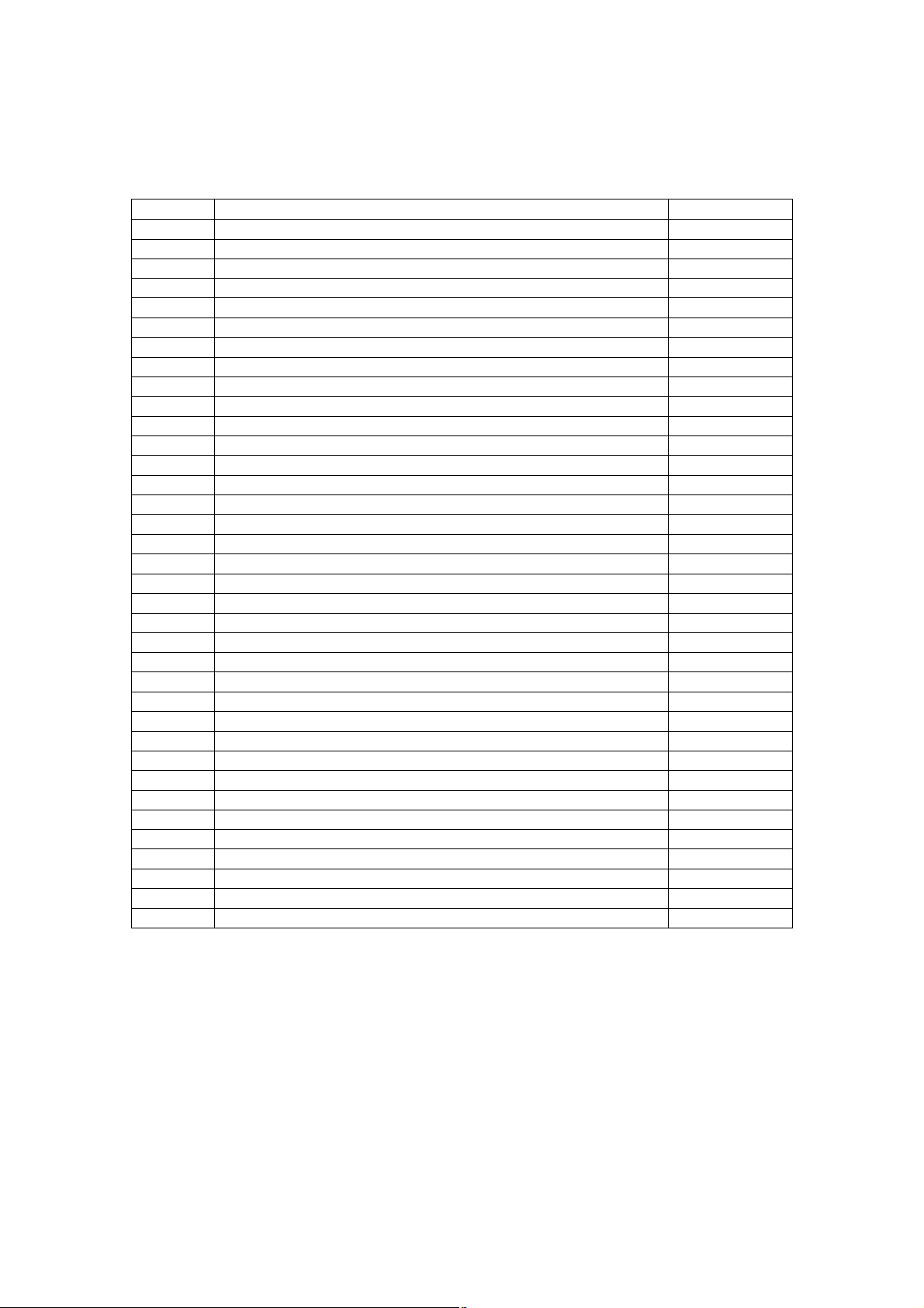
2.1.3Error in Internet FAX / Scanning Function
1)Internet FAX related error
Error codeClassificationTroubleshooting
1C10System access abnormalityP. 5-98
1C11Insufficient memoryP. 5-98
1C12Message reception errorP. 5-98
1C13Message transmission errorP. 5-98
1C14Invalid parameterP. 5-98
1C15Exceeding file capacityP. 5-98
1C20System management module access abnormalityP. 5-98
1C21Job control module access abnormalityP. 5-98
1C22Job control module access abnormalityP. 5-98
1C30Directory creation failureP. 5-99
1C31File creation failureP. 5-99
1C32File deletion failureP. 5-98
1C33File access failureP. 5-99
1C40Image conversion abnormalityP. 5-99
1C60HDD full failure during processingP. 5-99
1C61Address Book reading failureP. 5-99
1C62Memory acquiring failureP. 5-99
1C63Terminal IP address unsetP. 5-99
1C64Terminal mail address unsetP. 5-99
1C65SMTP address unsetP. 5-99
1C66Server time time-out errorP. 5-99
1C67NIC time time-out errorP. 5-99
1C68NIC access errorP. 5-99
1C69SMTP server connection errorP. 5-99
1C6AHOST NAME errorP. 5-99
1C6BTerminal mail address errorP. 5-100
1C6CDestination mail address errorP. 5-100
1C6DSystem errorP. 5-99
1C70SMTP client OFFP. 5-100
1C71SMTP authentication errorP. 5-100
1C72POP before SMTP errorP. 5-100
1C80Internet FAX transmission failure when processing E-mail job receivedP. 5-100
1C81Onramp Gateway transmission failureP. 5-100
1C82Internet FAX transmission failure when processing FAX job receivedP. 5-100
1CC0Job canceling -
1CC1Power failureP. 5-100
e-STUDIO281c/351c/451c ERROR CODE AND SELF-DIAGNOSTIC MODE© June 2005 TOSHIBA TEC
2 - 14
Page 15
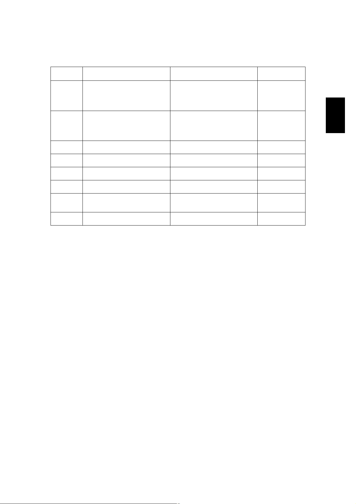
2)RFC related error
Error code
2500Syntax error, command unrecog-
2501Syntax error in parameters or argu-
2503Bad sequence of commandsDestination mail address error
2504Command parameter not imple-
2550Mailbox unavailableDestination mail address error
2551User not localDestination mail address error
2552Insufficient system storageTerminal/Destination mail address
2553Mailbox name not allowedDestination mail address error
Message displayed in
the TopAccess screen
nized
ments
mented
ContentsTroubleshooting
HOST NAME error(RFC: 500)
Destination mail address error
(RFC: 500)
Terminal mail address error
(RFC: 500)
HOST NAME error(RFC: 501)
Destination mail address error
(RFC: 501)
Terminal mail address error
(RFC: 501)
(RFC: 503)
HOST NAME error
(RFC: 504)
(RFC: 550)
(RFC: 551)
error
(RFC: 552)
(RFC: 553)
P. 5-101
P. 5-101
P. 5-101
P. 5-101
P. 5-101
P. 5-101
P. 5-101
P. 5-101
2
© June 2005 TOSHIBA TECe-STUDIO281c/351c/451c ERROR CODE AND SELF-DIAGNOSTIC MODE
2 - 15
Page 16
3)Electronic Filing related error
Error code
2B10There was no applicable job.No applicable job error in job control
2B11Job status failed.JOB status abnormalityP. 5-102
2B20Failed to access file.File library function errorP. 5-102
2B30Insufficient disk space.Insufficient disk space in /BOX parti-
2B31Failed to access Electronic Filing.Status of specified Electronic Filing
2B32Failed to print Electronic Filing docu-
2B50Failed to process image.Image library errorP. 5-102
2B51Failed to process print image.List library errorP. 5-102
2B71Document(s) expire(s) in a few daysDocuments expiring in a few days
2B80Hard Disk space for Electronic Filing
2B90Insufficient Memory.Insufficient memory capacityP. 5-102
2BA0Invalid Box password specified.Invalid Box passwordP. 5-102
2BB0Job canceledJob canceling-
2BB1Power failure occurredPower failureP. 5-102
2BC0System fatal error.Fatal failure occurredP. 5-102
2BC1Failed to acquire resource.System management module
2BD0Power failure occurred during e-Fil-
2BE0Failed to get machine parameter.Machine parameter reading failureP. 5-103
2BF0Maximum number of page range is
2BF1Maximum number of document
2BF2Maximum number of folder range is
Message displayed in
the TopAccess screen
ment.
nearly full.
ing restoring.
reached.
range is reached.
reached.
ContentsTroubleshooting
module
tion
or folder is undefined or being created/deleted
Electronic Filing printing failure:
Specified document can not be
printed because of client#s access
(being edited, etc.).
exist
Hard disk space in /BOX partition is
nearly full (90%).
resource acquiring failure
Power failure occurred during restoring of Electronic Filing
Exceeding maximum number of
pages
Exceeding maximum number of documents
Exceeding maximum number of folders
P. 5-102
P. 5-102
P. 5-102
P. 5-102
-
-
P. 5-102
P. 5-102
P. 5-103
P. 5-103
P. 5-103
e-STUDIO281c/351c/451c ERROR CODE AND SELF-DIAGNOSTIC MODE© June 2005 TOSHIBA TEC
2 - 16
Page 17
4)E-mail related error
Error code
2C10Illegal Job statusSystem access abnormalityP. 5-104
2C11Not enough memoryInsufficient memoryP. 5-104
2C12Illegal Job statusMessage reception errorP. 5-104
2C13Illegal Job statusMessage transmission errorP. 5-104
2C14Invalid parameter specifiedInvalid parameterP. 5-104
2C15Message size exceeded limit or max-
2C20Illegal Job statusSystem management module access
2C21Illegal Job statusJob control module access abnor-
2C22Illegal Job statusJob control module access abnor-
2C30Failed to create directoryDirectory creation failureP. 5-104
2C31Failed to create fileFile creation failureP. 5-104
2C32Failed to delete fileFile deletion failureP. 5-104
2C33Failed to create fileFile access failureP. 5-104
2C40Failed to convert image file formatImage conversion abnormalityP. 5-104
2C60Failed to process your Job. Insuffi-
2C61Failed to read AddressBookAddress Book reading failureP. 5-104
2C62Not enough memoryMemory acquiring failureP. 5-104
2C63Invalid Domain AddressTerminal IP address unsetP. 5-104
2C64Invalid Domain AddressTerminal mail address unsetP. 5-105
2C65Failed to connect to SMTP serverSMTP address unsetP. 5-105
2C66Failed to connect to SMTP serverServer time time-out errorP. 5-105
2C67Failed to send E-Mail messageNIC time time-out errorP. 5-105
2C68Failed to send E-Mail messageNIC access errorP. 5-105
2C69Failed to connect to SMTP serverSMTP server connection errorP. 5-105
2C6AFailed to send E-Mail messageHOST NAME error (No RFC error)P. 5-105
2C6BInvalid address specified in From:
2C6CInvalid address specified in To: fieldDestination mail address error (No
2C6DNIC system errorSystem errorP. 5-105
2C70SMTP service is not availableSMTP client OFFP. 5-105
2C71Failed SMTP AuthenticationSMTP authentication errorP. 5-105
2C72POP Before SMTP Authentication
2C80Failed to process received E-mail jobE-mail transmission failure when pro-
2C81Failed to process received Fax jobProcess failure of FAX job receivedP. 5-105
2CC0Job canceledJob canceling-
2CC1Power failure occurredPower failureP. 5-106
Message displayed in
the TopAccess screen
imum size
cient disk space.
field
Failed
ContentsTroubleshooting
2
Exceeding file capacityP. 5-104
P. 5-104
abnormality
P. 5-104
mality
P. 5-104
mality
HDD full failure during processingP. 5-104
Terminal mail address errorP. 5-105
P. 5-105
RFC error)
POP before SMTP errorP. 5-105
P. 5-105
cessing E-mail job received
© June 2005 TOSHIBA TECe-STUDIO281c/351c/451c ERROR CODE AND SELF-DIAGNOSTIC MODE
2 - 17
Page 18

5)File sharing related error
Error code
2D10Illegal Job statusSystem access abnormalityP. 5-107
2D11Not enough memoryInsufficient memoryP. 5-107
2D12Illegal Job statusMessage reception errorP. 5-107
2D13Illegal Job statusMessage transmission errorP. 5-107
2D14Invalid parameter specifiedInvalid parameterP. 5-107
2D15There are too many documents in the
2D20Illegal Job statusSystem management module access
2D21Illegal Job statusJob control module access abnor-
2D22Illegal Job statusJob control module access abnor-
2D30Failed to create directoryDirectory creation failureP. 5-107
2D31Failed to create fileFile creation failureP. 5-107
2D32Failed to delete fileFile deletion failureP. 5-107
2D33Failed to create fileFile access failureP. 5-107
2D40Failed to convert image file formatImage conversion abnormalityP. 5-107
2D60Failed to copy fileFile library access abnormalityP. 5-107
2D62Failed to connect to network destina-
2D63Specified network path is invalid.
2D64Logon to file server failed. Check
2D65There are too many documents in the
2D66Failed to process your Job. Insuffi-
2D67FTP service is not availableFTP service not availableP. 5-108
2D68File Sharing service is not availableFile sharing service not availableP. 5-108
2DA0Expired scan documents deleted
2DA1Expired Sent Fax documents deleted
2DA2Expired Received Fax documents
2DA3Scanned documents in shared folder
2DA4Sent Fax Documents in shared folder
2DA5Received Fax Documents in shared
2DA6Failed to delete file.File deletion failureP. 5-107
2DA7Failed to acquire resource.Resource acquiring failureP. 5-107
2DC0Job canceledJob canceling2DC1Power failure occurredPower failureP. 5-108
Message displayed in
the TopAccess screen
folder. Failed in creating new document.
tion. Check destination path
Check destination path
username and password
folder. Failed in creating new document.
cient disk space.
from share folder.
from shared folder.
deleted from shared folder.
deleted upon user#s request.
deleted upon user#s request.
folder deleted upon user#s request.
ContentsTroubleshooting
Exceeding document numberP. 5-107
P. 5-107
abnormality
P. 5-107
mality
P. 5-107
mality
File server connection errorP. 5-107
Invalid network pathP. 5-107
Login failureP. 5-108
Exceeding documents in folder:
P. 5-108
Creating new document is failed.
HDD full failure during processingP. 5-108
Periodical deletion of scanned docu-
-
ments completed properly.
Periodical deletion of transmitted
-
FAX documents completed properly.
Periodical deletion of received FAX
-
documents completed properly.
Manual deletion of scanned docu-
-
ments completed properly.
Manual deletion of transmitted FAX
-
documents completed properly.
Manual deletion of received FAX
-
documents completed properly.
e-STUDIO281c/351c/451c ERROR CODE AND SELF-DIAGNOSTIC MODE© June 2005 TOSHIBA TEC
2 - 18
06/08
Page 19
6)E-mail reception related error
Error code
3A10MIME Error has been detected in the
3A11MIME Error has been detected in the
3A12MIME Error has been detected in the
3A20Analyze Error has been detected in
3A21Analyze Error has been detected in
3A22Analyze Error has been detected in
3A30Whole partial mails were not reached
3A40Partial Mail Error has been detected
3A50HDD Full Error has been occurred in
3A51HDD Full Error has been occurred in
3A52HDD Full Error has been occurred in
3A60HDD Full Warning has been occurred
3A61HDD Full Warning has been occurred
3A62HDD Full Warning has been occurred
3A70Receiving partial mail was aborted
3A80Partial mail was received during the
3A81Partial mail was received during the
3A82Partial mail was received during the
3B10Format Error has been detected in
3B11Format Error has been detected in
3B12Format Error has been detected in
Message displayed in
the TopAccess screen
received mail.
received mail. This mail has been
transferred to the administrator.
received mail. This mail could not be
transferred to the administrator.
the received mail.
the received mail. This mail has been
transferred to the administrator.
the received mail. This mail could not
be transferred to the administrator.
by timeout.
in the received mail.
this mail.
this mail. This mail has been transferred to the administrator.
this mail. This mail could not be
transferred to the administrator.
in this mail.
in this mail. This mail could not be
transferred to the administrator.
in this mail. This mail could not be
transferred to the administrator.
since the partial mail setting has
been changed to Disable.
partial mail setting is disabled.
partial mail setting is disabled. This
mail has been transferred to the
administrator.
partial mail setting is disabled. This
mail could not be transferred to the
administrator.
the received mail.
the received mail. This mail has been
transferred to the administrator.
the received mail. This mail could not
be transferred to the administrator.
ContentsTroubleshooting
E-mail MIME errorP. 5-109
P. 5-109
P. 5-109
E-mail analysis errorP. 5-109
P. 5-109
P. 5-109
Partial mail time-out errorP. 5-109
Partial mail related errorP. 5-109
Insufficient HDD capacity errorP. 5-109
P. 5-109
P. 5-109
Warning of insufficient HDD capacityP. 5-109
P. 5-109
P. 5-109
Warning of partial mail interruptionP. 5-109
Partial mail reception setting OFFP. 5-109
P. 5-109
P. 5-109
E-mail format errorP. 5-109
P. 5-109
P. 5-109
2
© June 2005 TOSHIBA TECe-STUDIO281c/351c/451c ERROR CODE AND SELF-DIAGNOSTIC MODE
2 - 19
Page 20
Error code
Message displayed in
the TopAccess screen
3B20Content-Type Error has been
detected in the received mail.
3B21Content-Type Error has been
detected in the received mail. This
mail has been transferred to the
administrator.
3B22Content-Type Error has been
detected in the received mail. This
mail could not be transferred to the
administrator.
3B30Charset Error has been detected in
the received mail.
3B31Charset Error has been detected in
the received mail. This mail has been
transferred to the administrator.
3B32Charset Error has been detected in
the received mail. This mail could not
be transferred to the administrator.
3B40Decode Error has been detected in
the received mail.
3B41Decode Error has been detected in
the received mail. This mail has been
transferred to the administrator.
3B42Decode Error has been detected in
the received mail. This mail could not
be transferred to the administrator.
3C10Tiff Analyze Error has been detected
in the received mail.
3C11Tiff Analyze Error has been detected
in the received mail. This mail has
been transferred to the administrator.
3C12Tiff Analyze Error has been detected
in the received mail. This mail could
not be transferred to the administrator.
3C13Tiff Analyze Error has been detected
in the received mail.
3C20Tiff Compression Error has been
detected in the received mail.
3C21Tiff Compression Error has been
detected in the received mail. This
mail has been transferred to the
administrator.
3C22Tiff Compression Error has been
detected in the received mail. This
mail could not be transferred to the
administrator.
3C30Tiff Resolution Error has been
detected in the received mail.
3C31Tiff Resolution Error has been
detected in the received mail. This
mail has been transferred to the
administrator.
3C32Tiff Resolution Error has been
detected in the received mail. This
mail could not be transferred to the
administrator.
ContentsTroubleshooting
Content-Type errorP. 5-109
P. 5-109
P. 5-109
Charset errorP. 5-109
P. 5-109
P. 5-109
E-mail decode errorP. 5-109
P. 5-109
P. 5-109
TIFF analysis errorP. 5-109
P. 5-109
P. 5-109
P. 5-109
E-mail format errorP. 5-109
P. 5-109
P. 5-109
Content-Type errorP. 5-110
P. 5-110
P. 5-110
e-STUDIO281c/351c/451c ERROR CODE AND SELF-DIAGNOSTIC MODE© June 2005 TOSHIBA TEC
2 - 20
Page 21
Error code
3C40Tiff Paper Size Error has been
3C41Tiff Paper Size Error has been
3C42Tiff Paper Size Error has been
3C50Offramp Destination Error has been
3C51Offramp Destination Error has been
3C52Offramp Destination Error has been
3C60Offramp Security Error has been
3C61Offramp Security Error has been
3C62Offramp Security Error has been
3C70Power Failure has been occurred in
3D10SMTP Destination Error has been
3D20Offramp Destination limitation Error
3D30Fax Board Error has been occurred
3E10POP3 Connection Error has been
3E20POP3 Connection Timeout Error has
3E30POP3 Login Error has been occurred
3E40POP3 Login Error occurred in the
3F00File I/O Error has been occurred in
3F10 P. 5-110
3F20 P. 5-110
3F30 P. 5-110
3F40 P. 5-110
Message displayed in
the TopAccess screen
detected in the received mail.
detected in the received mail. This
mail has been transferred to the
administrator.
detected in the received mail. This
mail could not be transferred to the
administrator.
detected in the received mail.
detected in the received mail. This
mail has been transferred to the
administrator.
detected in the received mail. This
mail could not be transferred to the
administrator.
detected in the received mail.
detected in the received mail. This
mail has been transferred to the
administrator.
detected in the received mail. This
mail could not be transferred to the
administrator.
Email receiving.
detected in the received mail. This
mail was deleted.
has been detected in the received
mail.
in the received mail.
occurred in the received mail.
been occurred in the received mail.
in the received mail.
received mail.
this mail. The mail could not be
received until File I/O is recovered.
ContentsTroubleshooting
Charset errorP. 5-110
E-mail decode errorP. 5-110
TIFF analysis errorP. 5-110
Power failure errorP. 5-110
Destination address errorP. 5-110
Offramp destination limitation errorP. 5-110
FAX board errorP. 5-110
POP3 server connection errorP. 5-110
POP3 server connection time-out
error
POP3 login errorP. 5-110
POP3 login method errorP. 5-110
File I/O errorP. 5-110
P. 5-110
P. 5-110
P. 5-110
P. 5-110
P. 5-110
P. 5-110
P. 5-110
2
© June 2005 TOSHIBA TECe-STUDIO281c/351c/451c ERROR CODE AND SELF-DIAGNOSTIC MODE
2 - 21
Page 22
2.1.4Printer function error
Following codes are displayed at the end of the user name on the print job log screen.
Error codeContentsTroubleshooting
402FPage memory size error - 1200 dpi network print is performed by the equip-
ment with 128 MB (standard) memory.
4031HDD full during print - Large quantity image data by private print or invalid
network print are saved in HDD.
4032Private-print-only error: Jobs other than Private print jobs cannot be per-
formed.
4033Printing data storing limitation error: Printing with its data being stored to the
HDD temporarily (Proof print, Private print, Scheduled print, etc.) cannot be
performed.
4034e-Filing storing limitation error: Printing with its data being stored to the HDD
(print and e-Filing, print to e-Filing, etc.) cannot be performed.
4035Local file storing limitation error: Network FAX or Internet FAX cannot be sent
when "Local" is selected for the destination of the file to save.
4036User authentication error: The user who intended to print a document is not
registered as a user.
A221Print job cancellation - Print job (copy, list print, network print) is deleted from
the print job screen.
A222Print job power failure - The power of the equipment is turned OFF during
print job (copy, list print, network print).
A290Limit over error (Black): The numbers of output pages have exceeded those
specified with both of the department code and the user code at the same
time.
A291Limit over error (Black): The number of output pages has exceeded the one
specified with the user code.
A292Limit over error (Black): The number of output pages has exceeded the one
specified with the department code.
A2A0Limit over error (Color): The numbers of output pages have exceeded those
specified with both of the department code and the user code at the same
time.
A2A1Limit over error (Color): The number of output pages has exceeded the one
specified with the user code.
A2A2Limit over error (Color): The number of output pages has exceeded the one
specified with the department code.
P. 5-111
P. 5-111
P. 5-111
P. 5-111
P. 5-111
P. 5-111
P. 5-111
P. 5-111
P. 5-111
P. 5-111
P. 5-111
P. 5-111
P. 5-111
P. 5-111
P. 5-111
e-STUDIO281c/351c/451c ERROR CODE AND SELF-DIAGNOSTIC MODE© June 2005 TOSHIBA TEC
2 - 22
Page 23
<<Error history>>
In the setting mode (08-253), the latest twenty groups of error data will be displayed.
Display example
EA10 99999999 05 06 14 17 57 32 064 064 23621000000
Error codeTotal counterYY MM DD HH MM SSMMMNNNABCDEFHIJLO
4 digits8 digits12 digits (Year is indicated
3 digits3 digits11 digits
with its last two digits.)
APaper source
0: Not selected 1: Bypass feed 2: LCF 3: Upper drawer 4: Lower drawer 5: PFP upper drawer
6: PFP lower drawer 7: Unused 8: Unused
BPaper size code
0: A5/ST 1: A5-R 2: ST-R 3: LT, 4: A4 5: B5-R 6: LT-R 7: A4-R 8: OTHER/UNIV 9: B5,
A: FOLIO/COMP B: LG C: B4 D: LD E: A3 F: 13"LG G: Unsed H: A6-R I: Post card J: 8.5"SQ
K: A3-wide L: 305×457 mm M: 8K N: 16K-R O: 16K Z: Not selected
CSort mode/staple mode
0: Non-sort/Non-staple 1: Group 2: Sort 7: Front staple
8: Double staple 9: Rear staple A: Saddle stitch
DADF mode
0: Unused 1: AUTO FEED (SADF) 2: STACK FEED
EAPS/AMS mode
0: Not selected 1: APS 2: AMS
FDuplex mode
0: Not selected 1: Book 2: Double-sided/Single-sided 4: Double-sided/Duplex copying
8: Single-sided/Duplex copying
GUnused
HImage shift
0: Unused 1: Book 2: Left 4: Right
IEditing
0: Unused 1: Masking 2: Trimming 3: Mirror image 4: Unused
JEdge erase/Dual-page
0: Unused 1: Edge erase 2: Dual-page 3: Edge erase & Dual-page
KUnused
LFunction
0: Unused 1: Copying 2: FAX/Internet FAX transmission 3: FAX/Internet FAX/E-mail reception printing
4: Unused 5: Printing/List print 6: Scan/E-mail transmission
MMMPrimary scanning reproduction ratio (Display in hexadecimal)
(Mx256)+(Mx16)+M
NNNSecondary scanning reproduction ratio (Display in hexadecimal)
(Nx256)+(Nx16)+N
OColor mode
0: Auto color 1: Full color 2: Black 3: Unused 4: Twin color copy 5: Gray scale
6: Unused 7: Image smoothing
2
© June 2005 TOSHIBA TECe-STUDIO281c/351c/451c ERROR CODE AND SELF-DIAGNOSTIC MODE
2 - 23
Page 24
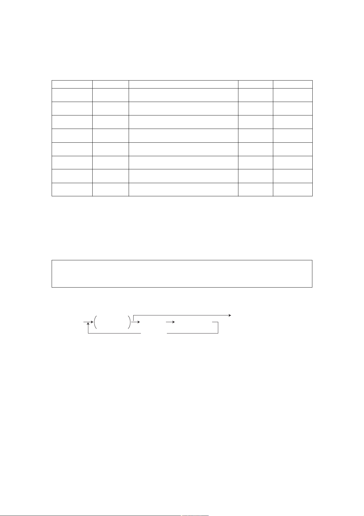
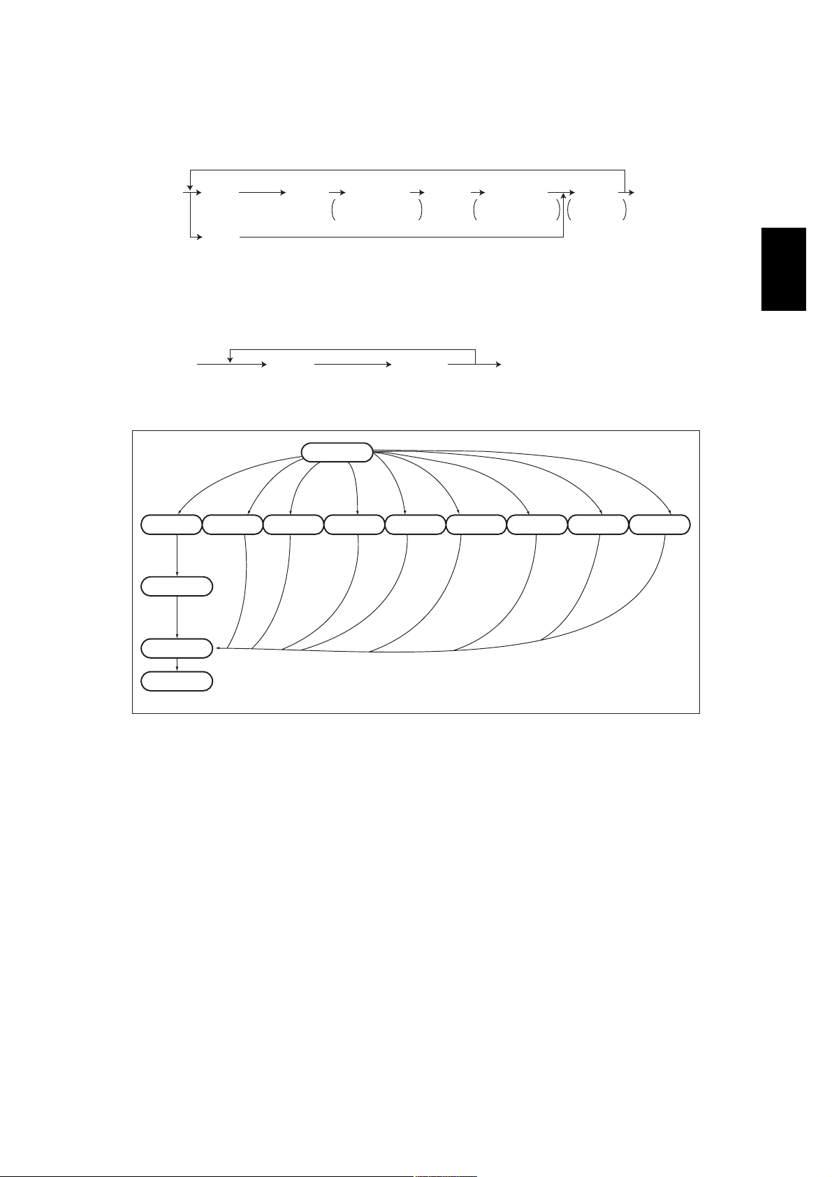
2.2Self-diagnosis Modes
ModeFor startContentsFor exitDisplay
Control panel
check mode
Test mode[0]+[3]+
Test print mode[0]+[4]+
Adjustment
mode
Setting mode[0]+[8]+
List print mode[9]+[START]+
PM support
mode
Firmware
update mode
Notes:
1.To enter the desired mode, turn ON the power while two digital keys designated to each mode
(e.g. [0] and [5]) are pressed simultaneously.
2.When the optional FAX unit is installed, Faxes received automatically during the self-diagnosis mode may not be printed out. Be sure to disconnect the modular code from the line connectors (LINE1, LINE2) of the equipment before starting the self-diagnosis mode. Also, be
sure to finish the self-diagnosis mode by turning the power OFF and back ON before connecting the modular code.
[0]+[1]+
[POWER]
[POWER]
[POWER]
[0]+[5]+
[POWER]
[POWER]
[POWER]
[6]+[START]+
[POWER]
[8]+[9]+
[POWER]
All LEDs on the control panel are lit, and all
the LCD pixels blink.
Checks the status of input/output signals.[POWER]
Outputs the test patterns.[POWER]
Adjusts various items.[POWER]
Sets various items.[POWER]
Prints out the data lists of the codes 05 and
08, PM support mode and pixel counter.
Clears each counter.[POWER]
Performs updating of the system firmware.[POWER]
[POWER]
OFF/ON
OFF/ON
OFF/ON
OFF/ON
OFF/ON
[POWER]
OFF/ON
OFF/ON
OFF/ON
-
100% C A4
TEST MODE
100% P A4
TEST PRINT
100% A A4
TEST MODE
100% D
TEST MODE
100% UA A4
LIST PRINT
100% K
TEST MODE
-
To exit from Adjustment mode and Setting mode:
Shut down the equipment. When the power should be turned OFF, be sure to shut down the equipment by pressing the [ENERGY SAVER] button for a few seconds.
<Operation procedure>
$ Control panel check mode (01):
ЕрГЕпГ
ЕРСЙЫОГ
ÔÛÜ ´·¬ñ
ÔÝÜ ¾´·²µ·²¹
ЕНМЯОМГ
ЕНМЯОМГ
øÞ«¬¬±² ½¸»½µ÷
ЕРСЙЫОГ СЪЪсСТ
øÛ¨·¬÷
Notes:
1.A mode can be canceled by [POWER] OFF/ON when the LED is lit and the LCD is blinking.
2.Button Check
Buttons with LED(Press to turn OFF the LED.)
Buttons without LED(Press to display the message on the control panel.)
Button on touch panel(Press to display the screen on the control panel at power-ON.)
$ Test mode (03): Refer to 2.2.1. Input check (test mode 03)! and 2.2.2. Output check (test mode
03)!.
$ Test print mode (04): Refer to 2.2.3. Test print mode (04)!.
$ Adjustment mode (05): Refer to 2.2.4. Adjustment mode (05)!.
$ Setting mode (08): Refer to 2.2.5. Setting mode (08)!.
e-STUDIO281c/351c/451c ERROR CODE AND SELF-DIAGNOSTIC MODE© June 2005 TOSHIBA TEC
2 - 24
06/08
Page 25
$ List print mode (9S): The procedure varies depending on the code.
ЕзГЕНМЯОМГ
ЕРСЙЫОГ
øݱ¼»÷
ïðïæ ß¼¶«-¬³»²¬ ³±¼» øðë÷
ïðîæ Í»¬¬·²¹ ³±¼» øðè÷
øݱ¼»÷
ïðíæ ÐÓ -«°°±®¬ ³±¼»
ïðìæ ͬ±®»¼ ·²º±®³¿¬·±² ±º °·¨»´ ½±«²¬»® ø¬±²»® ½¿®¬®·¼¹» ®»º»®»²½»÷
ïðëæ ͬ±®»¼ ·²º±®³¿¬·±² ±º °·¨»´ ½±«²¬»® ø-»®ª·½» ¬»½¸²·½·¿² ®»º»®»²½»÷
ïðêæ Û®®±® ¸·-¬±®§ øÓ¿¨·³«³ ïððð ·¬»³-÷
ïðéæ Û®®±® ¸·-¬±®§ øÔ¿¬»-¬ èð ·¬»³-÷
ЕНМЯОМГЕНМЯОМГ
ÅÜ·¹·¬¿´ µ»§-Ã
Õ»§ ·² ¬¸» º·®-¬
½±¼» ¬± ¾» °®·²¬»¼
ÅÜ·¹·¬¿´ µ»§-Ã
Õ»§ ·² ¬¸» ´¿-¬
½±¼» ¬± ¾» °®·²¬»¼
$ PM support mode (6S):
ЕкГЕНМЯОМГ
ЕРСЙЫОГ
îæ ÐÓ Í«°°±®¬ ͽ®»»²
øݱ¼»÷
ЕНМЯОМГ
øÑ°»®¿¬·±² -¬¿®¬»¼÷
ЕРСЙЫОГ СЪЪсСТ
$ Firmware update mode (89): Refer to 6. FIRMWARE UPDATING!.
ЕРСЙЫОГ
ÑÒ
Ì»-¬ °®·²¬
³±¼»
ß¼¶«-¬³»²¬
³±¼»
Í»¬¬·²¹
³±¼»
É¿®³·²¹ «°
λ¿¼§
Ò±®³¿´
ݱ²¬®±´ °¿²»´
½¸»½µ ³±¼»
ЕрГЕпГЕрГЕнГЕрГЕмГЕрГЕлГЕрГЕиГЕзГЕНМЯОМГЕкГЕНМЯОМГЕиГЕзГ
Ì»-¬ ³±¼»
øÛ¨·¬÷
Ô·-¬ °®·²¬
³±¼»
ЕНМЯОМГ
Ô·-¬ -¬¿®¬- ¬±
¾» °®·²¬»¼
ÐÓ -«°°±®¬
³±¼»
ЕРСЙЫОГ
СЪЪсСТ
øÛ¨·¬÷
Ú·®³©¿®»
«°¼¿¬» ³±¼»
2
ЕРСЙЫОГ
ÑÚÚ
öï
̱ «-»®
ͬ¿¬» ¬®¿²-·¬·±² ¼·¿¹®¿³ ±º -»´ºó¼·¿¹²±-·- ³±¼»-
Fig. 2-1
*1Turn OFF the power after using the self-diagnosis mode, and leave the equipment to the user.
© June 2005 TOSHIBA TECe-STUDIO281c/351c/451c ERROR CODE AND SELF-DIAGNOSTIC MODE
2 - 25
Page 26
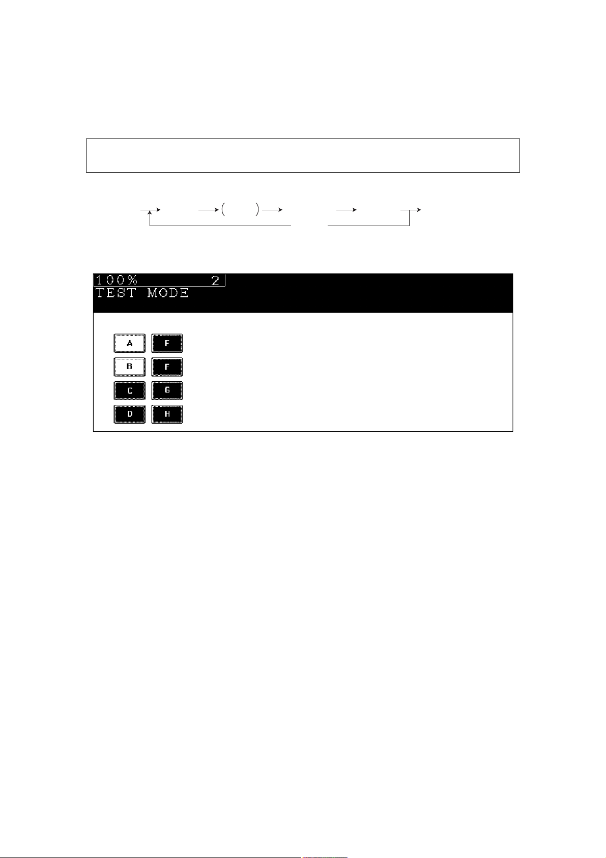
2.2.1Input check (Test mode 03)
The status of each input signal can be checked by pressing the [FAX] button, [COPY] button and
the digital keys in the test mode (03).
<Operation procedure>
ЕрГЕнГ
ЕРСЙЫОГ
ЕНМЯОМГ
ЕЪЯИГ
±®
ЕЭСРЗГ
ÅÜ·¹·¬¿´ µ»§-Ã
ЕЭФЫЯОГ
øÔÝÜ ÑÒ÷
ЕРСЙЫОГ СЪЪсСТ
øÛ¨·¬÷
Note: Note:
Initialization is performed before the equipment enters the test mode.
Fig. 2-2 Example of display during input check
Items to be checked and the condition of the equipment when the buttons [A] to [H] are highlighted are
listed in the following pages.
e-STUDIO281c/351c/451c ERROR CODE AND SELF-DIAGNOSTIC MODE© June 2005 TOSHIBA TEC
2 - 26
Page 27
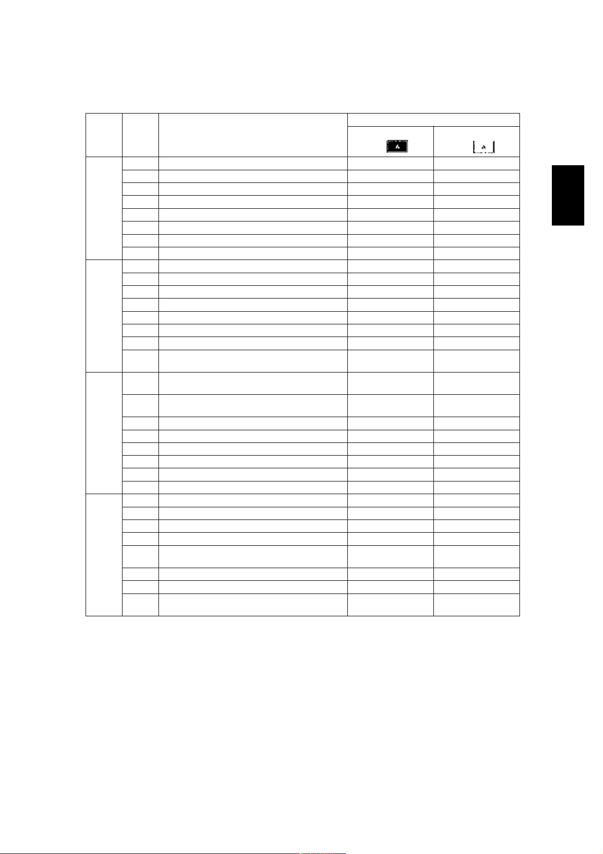
[FAX] button: OFF/[COPY] button: OFF ([FAX] LED: OFF/[COPY] LED: OFF)
Digital
key
[1]
[2]
[3]
[4]
ButtonItems to check
ABypass unit connectionNot connectedConnected
BADU connectionNot connectedConnected
C---
DLCF connectionNot connectedConnected
E---
F---
G---
HLCF drawer detection switchDrawer not installedDrawer present
APFP upper drawer detection switchDrawer not installedDrawer present
B---
CPFP upper drawer paper stock sensorPaper almost emptyPaper present
DPFP upper drawer feed sensorPaper presentNo paper
EPFP connectionNot connectedConnected
FPFP side cover open/close switchCover openedCover closed
GPFP upper drawer empty sensorNo paperPaper present
HPFP upper drawer tray-up sensorTray at upper limit
ALCF tray bottom sensorTray at bottom posi-
BLCF standby side paper misload detection sen-
sor
C---
D---
E---
F---
G---
HPaper stock sensor at LCF feed sidePaper presentNo paper
APFP lower drawer detection switchDrawer not installedDrawer present
B---
CPFP lower drawer paper stock sensorPaper almost emptyPaper present
DPFP lower drawer feed sensorPaper presentNo paper
EPFP motor rotation status (Motor is rotating at
output mode (03))
F---
GPFP lower drawer empty sensorNo paperPaper present
HPFP lower drawer tray-up sensorTray at upper limit
Highlighted display
e.g.
position
tion
Properly loadedPaper misload
Abnormal rotationNormal rotation
position
Contents
Normal display
e.g.
2
Other than upper
limit position
Other than upper
limit position
Other than upper
limit position
© June 2005 TOSHIBA TECe-STUDIO281c/351c/451c ERROR CODE AND SELF-DIAGNOSTIC MODE
2 - 27
Page 28
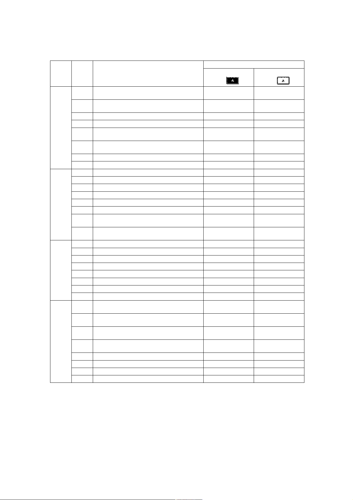
Digital
key
[5]
[6]
[7]
[8]
Contents
ButtonItems to check
Highlighted display
e.g.
ALCF end fence home position sensorFence home posi-
tion
Normal display
e.g.
Other than home
position
BLCF end fence stop position sensorFence stop positionOther than stop
position
CEmpty sensor at LCF standby sideNo paperPaper present
DLCF side cover open/close switchCover closedCover opened
ELCF motor rotation status (Motor is rotating at
Abnormal rotationNormal rotation
output mode (03))
FLCF tray-up sensorTray at upper limit
position
Other than upper
limit position
GLCF feed sensorNo paperPaper present
HEmpty sensor at LCF feed sideNo paperPaper present
ALower drawer detection switchDrawer not installedDrawer present
BUpper drawer detection switchDrawer not installedDrawer present
CLower drawer paper stock sensorPaper almost emptyPaper present
DUpper drawer paper stock sensorPaper almost emptyPaper present
ELower drawer empty sensorNo paperPaper present
FUpper drawer empty sensorNo paperPaper present
GLower drawer tray-up sensorTray at upper limit
position
HUpper drawer tray-up sensorTray at upper limit
position
Other than upper
limit position
Other than upper
limit position
A---
B---
C---
D---
ESide cover open/close switchCover openedCover closed
FFront cover opening/closing switchCover openedCover closed
G---
HExit sensorPaper presentNo paper
ABypass feed paper width sensor 3
Bit 1Bit 0
(Refer to table1)
BBypass feed paper width sensor 2
Bit 1Bit 0
(Refer to table1)
CBypass feed paper width sensor 1
Bit 1Bit 0
(Refer to table1)
DBypass feed paper width sensor 0
Bit 1Bit 0
(Refer to table1)
EBypass sensorNo paperPaper present
FADU opening/closing switchADU openedADU closed
GADU exit sensorPaper presentNo paper
HADU entrance sensorPaper presentNo paper
e-STUDIO281c/351c/451c ERROR CODE AND SELF-DIAGNOSTIC MODE© June 2005 TOSHIBA TEC
2 - 28
Page 29
Contents
Digital
key
[9]
[0]
ButtonItems to check
A---
B---
C---
D---
E---
FKey copy counter connectionNot connectedConnected
G---
H---
A---
B---
C---
D---
E---
F---
G---
H---
Highlighted display
e.g.
Normal display
e.g.
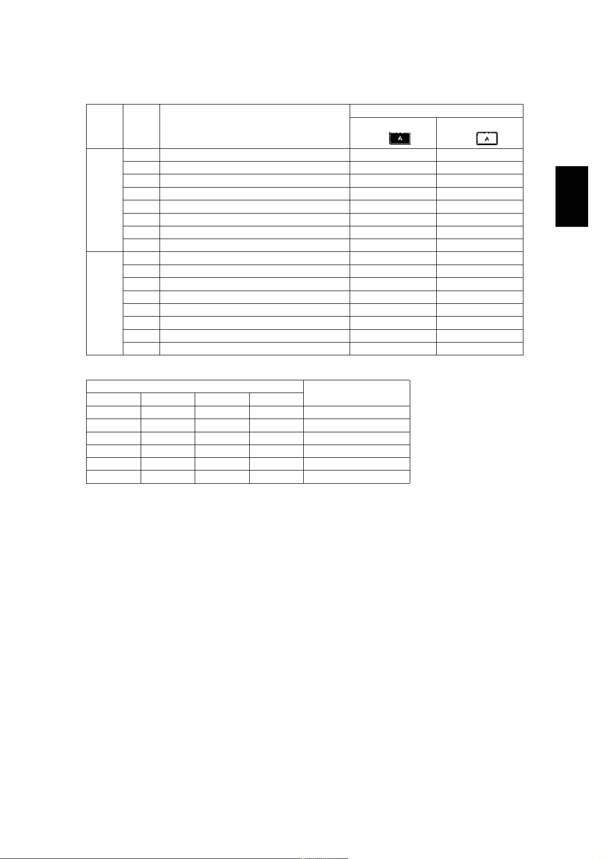
Table 1. Relation between the status of the bypass paper width sensor and paper size (width).
Bypass paper width sensor
3210
0111A3/LD
1011A4-R/LT-R
1101A5-R/ST-R
1110Card size
0011B4-R/LG
1001B5-R
Paper width size
2
© June 2005 TOSHIBA TECe-STUDIO281c/351c/451c ERROR CODE AND SELF-DIAGNOSTIC MODE
2 - 29
Page 30

[FAX] button: ON/[COPY] button: OFF ([FAX] LED: ON/[COPY] LED: OFF)
Digital
key
[1]
[2]
[3]
[4]
ButtonItems to check
A2nd transfer roller position detection sensorReleasedContacted
BBlack developer contact timing detection sensorReleasing move-
CBlack developer contact position detection sen-
sor
DMain motor rotation status
(Motor is rotating at Output Mode (03))
EDeveloper motor rotation status
(Motor is rotating at Output Mode (03))
FTransport motor rotation status
(Motor is rotating at Output Mode (03))
GPolygonal motor rotation status
(Motor is rotating at Output Mode (03))
H24V Power supplyPower OFFPower ON
AIPC board connectionNot connectedConnected
BColor toner cartridge sensorNormallyInstallation fault
CRevolver home position sensorHome positionOther than home
D---
E---
FToner bag full detection sensorToner bag fullNot full
GBlack auto-toner sensor connectionNot connectedConnected
H---
A---
B---
C---
D---
E---
F---
GLower drawer feed sensorNo paperPaper present
HUpper drawer feed sensorPaper presentNo paper
A---
B---
C---
D---
EBridge unit connectionNot connectedConnected
FColor auto-toner sensor connectionNot connectedConnected
G---
H---
Highlighted display
e.g.
ment
Released positionContacted position
Abnormal rotationNormal rotation
Abnormal rotationNormal rotation
Abnormal rotationNormal rotation
Abnormal rotationNormal rotation
Contents
Normal display
e.g.
Contacting movement
position
e-STUDIO281c/351c/451c ERROR CODE AND SELF-DIAGNOSTIC MODE© June 2005 TOSHIBA TEC
2 - 30
Page 31

Digital
key
[5]
[6]
[7]
[8]
[9]
Contents
ButtonItems to check
A---
B---
C---
D---
E---
FRADF connectionRADF connectedNot connected
GPlaten sensorPlaten cove openedPlaten cover closed
HCarriage home position sensorHome positionOther than home
A---
B---
C---
DAPS sensor (APS-R)No originalOriginal present
EAPS sensor (APS-C)No originalOriginal present
FAPS sensor (APS-3)No originalOriginal present
GAPS sensor (APS-2)No originalOriginal present
HAPS sensor (APS-1)No originalOriginal present
ARADF tray sensorOriginal presentNo original
BRADF empty sensorOriginal presentNo original
CRADF jam access cover sensorCover openedCover closed
DRADF open/close sensorRADF openedRADF closed
ERADF exit sensorOriginal presentNo original
FRADF intermediate sensorOriginal presentNo original
GRADF read sensorOriginal presentNo original
HRADF registration sensorOriginal presentNo original
A---
B---
C---
D---
ERADF original length sensorOriginal presentNo original
FRADF original width sensor 1Original presentNo original
GRADF original width sensor 2Original presentNo original
H---
ABlack toner cartridge switchCartridge not
B---
C---
DBypass feed sensorNo paperPaper present
ERegistration sensorPaper presentNo paper
F---
G---
HTransfer belt home position sensorHome positionOther tha home
Highlighted display
e.g.
installed
Normal display
e.g.
position
Cartridge installed
position
2
© June 2005 TOSHIBA TECe-STUDIO281c/351c/451c ERROR CODE AND SELF-DIAGNOSTIC MODE
2 - 31
Page 32

Digital
key
[0]
Contents
ButtonItems to check
Highlighted display
e.g.
Normal display
e.g.
ABridge unit transport sensor 2Paper presentNo paper
BBridge unit cover open/close detection switchCover openedCover closed
CBridge unit transport sensor 1Paper presentNo paper
DBridge unit paper full detection sensorPaper not fullPaper full
E---
FCharger cleaner front position detection switchCleaner home posi-
tion
GCharger cleaner rear position detection switchCleaner rear posi-
tion
Other than home
position
Other than rear position
H---
e-STUDIO281c/351c/451c ERROR CODE AND SELF-DIAGNOSTIC MODE© June 2005 TOSHIBA TEC
2 - 32
Page 33

[FAX] button: OFF/[COPY] button: ON ([FAX] LED: OFF/[COPY] LED: ON)
Digital
key
[1]
[2]
[3]
[4]
[5]
[6]
[7]
[8]
ButtonItems to check
-Temperature/humidity sensor (displays temperature inside of the equipment)
-Temperature/humidity sensor (displays humidity
inside of the equipment)
-Drum thermistor (displays drum surface temperature)
A---
B--C--D--E--F--G--H--A--B--C--D--E--F--G--H--A--B--C--D--E--F--G--H--A--B--C--D--E--F--G--H--A--B--C--D--E--F--G--H---
Highlighted display
e.g.
-Temperature [°C]
-Humidity [%RH]
-Temperature [°C]
Contents
Normal display
e.g.
2
© June 2005 TOSHIBA TECe-STUDIO281c/351c/451c ERROR CODE AND SELF-DIAGNOSTIC MODE
2 - 33
Page 34

Digital
key
[9]
[0]
ButtonItems to check
A--B--C--D--E--F--G--H--A--B--C--DDongles for other equipments / Other USB
devices
EJudgement for acceptable USB storage device
(*1)
F--G--H---
Highlighted display
e.g.
ConnectableNot connectable
AcceptableNot acceptable
Contents
Normal display
e.g.
*1
$ Be sure to install the USB storage device to the equipment and check if the device can be used with
this code.
$ Be sure to turn OFF the write protection (the function to prevent data from erasure by the accidental
recording or deleting) of the USB storage device before performing the check, otherwise this code
cannot be used.
$ It may take some time (2 sec. to 10 sec.) before this check is completed depending on the USB stor-
age device.
e-STUDIO281c/351c/451c ERROR CODE AND SELF-DIAGNOSTIC MODE© June 2005 TOSHIBA TEC
2 - 34
05/11
Page 35

2.2.2Output check (test mode 03)
Status of the output signals can be checked by entering the following codes in the test mode 03.
<Operation procedure>
Procedure 1
ЕрГЕнГ
ЕРСЙЫОГ
øݱ¼»÷
ЕНМЯОМГ
Ñ°»®¿¬·±²
ÑÒ
ͬ±°
½±¼»
ЕНМЯОМГ
Ñ°»®¿¬·±²
ÑÚÚ
ЕРСЙЫОГ СЪЪсСТ
øÛ¨·¬÷
Procedure 2
ЕрГЕнГ
ЕРСЙЫОГ
øݱ¼»÷
ЕНМЯОМГЕЭФЫЯОГ
Ñ°»®¿¬·±²
Ѳ» ¼·®»½¬·±²
Ì»-¬ ³±¼»
-¬¿²¼¾§
ЕРСЙЫОГ СЪЪсСТ
øÛ¨·¬÷
Procedure 3
ЕрГЕнГ
ЕРСЙЫОГ
øݱ¼»÷ ЕНМЯОМГ ЕНМЯОМГ
Ñ°»®¿¬·±²
ÑÒ
Ñ°»®¿¬·±²
ÑÚÚ
ЕЭФЫЯОГ
Ì»-¬ ³±¼»
-¬¿²¼¾§
ЕРСЙЫОГ
СЪЪсСТ
øÛ¨·¬÷
Procedure 4
ЕрГЕнГ
ЕРСЙЫОГ
CodeFunctionCodeFunctionProcedure
101Main motor ON (Operational without
black developer unit)
102Toner motor K (normal rotation) ON152Code No.102 function OFF1
103Polygonal motor (600dpi) ON153Code No.103 function OFF1
108Registration clutch ON158Code No.108 function OFF1
109PFP motor ON159Code No.109 function OFF1
110ADU motor ON160Code No.110 function OFF1
112Developer motor ON (Operational with
black developer unit)
115Drum cleaning brush motor ON165Code No.115 function OFF1
116Transfer belt cleaner auger motor ON166Code No.116 function OFF1
118Laser ON168Code No.118 function OFF1
120Exit motor (normal rotation) ON170Code No.120 function OFF1
121Exit motor (reversal rotation) ON171Code No.121 function OFF1
122LCF motor ON172Code No.122 function OFF1
123Transport motor ON173Code No.123 function OFF1
124Toner motor K (reversal rotation) ON174Code No.124 function OFF1
125Color auto-toner sensor shutter sole-
noid ON (open)
126Color auto-toner sensor LED ON176Code No.126 function OFF1
øݱ¼»÷
ЕНМЯОМГ
ЕРСЙЫОГ СЪЪ
151Code No.101 function OFF1
162Code No.112 function OFF1
175Code No.125 function OFF1
2
© June 2005 TOSHIBA TECe-STUDIO281c/351c/451c ERROR CODE AND SELF-DIAGNOSTIC MODE
2 - 35
Page 36

CodeFunctionProcedure
201Upper drawer feed clutch ON/OFF3
202Lower drawer feed clutch ON/OFF3
203Lower transport clutch (high speed) ON/OFF3
204Bypass feed clutch ON/OFF3
205Lower transport clutch (low speed) ON/OFF3
206LCF pickup solenoid ON/OFF3
207LCF end fence reciprocating movement2
208LCF end fence motor ON/OFF3
209LCF feed clutch ON/OFF3
210LCF transport clutch ON/OFF3
218Key copy counter count up2
225PFP transport clutch ON/OFF3
226PFP upper drawer feed clutch ON/OFF3
228PFP lower drawer feed clutch ON/OFF3
232Bridge unit gate solenoid ON/OFF3
235Discharge LED ON/OFF3
241IH board cooling fan (low speed) ON/OFF3
242Upper drawer tray-up motor ON (tray up)2
243Lower drawer tray-up motor ON (tray up)2
248Developer bias (Black) [+DC] ON/OFF3
249Developer bias (Black) [-DC] ON/OFF3
252Main charger ON/OFF 3
261Scan motor ON (Automatically stops at limit position, speed can be changed by using
2
ZOOM button)
264SLG board cooling fan / Scanner unit cooling fan ON (high/low speed)1
265SLG board cooling fan / Scanner unit cooling fan OFF1
267Scanner exposure lamp ON/OFF3
268Laser unit cooling fan (high speed) ON/OFF3
271LCF tray-up motor UP/DOWN2
278PFP upper drawer tray-up motor ON (tray up)2
280PFP lower drawer tray-up motor ON (tray up)2
281RADF feed motor ON/OFF (normal rotation)3
282RADF feed motor ON/OFF (reverse rotation)3
283RADF read motor ON/OFF3
284RADF exit/reverse motor ON/OFF (normal rotation)3
285RADF exit/reverse motor ON/OFF (reverse rotation)3
294RADF reverse solenoid ON/OFF3
295Power OFF mode (for 200V series)4
297RADF fan motor ON/OFF3
410Power supply cooling fan (low speed) ON/OFF3
411Power supply cooling fan (high speed) ON/OFF3
412Internal cooling fan ON/OFF (low speed)3
e-STUDIO281c/351c/451c ERROR CODE AND SELF-DIAGNOSTIC MODE© June 2005 TOSHIBA TEC
2 - 36
06/08
Page 37

CodeFunctionProcedure
413Internal cooling fan ON/OFF (high speed)3
416IH board cooling fan (high speed) ON/OFF3
417Ozone exhaust fan (low speed) ON/OFF3
418Ozone exhaust fan (high speed) ON/OFF3
419Developer bias (Black) [AC] ON/OFF3
420Developer bias (Color) [+DC] ON/OFF3
421Developer bias (Color) [-DC1] ON/OFF3
422Developer bias (Color) [AC] ON/OFF3
4241st transfer roller bias [+] ON/OFF3
4251st transfer roller bias [-] ON/OFF3
4262nd transfer roller bias [+] ON/OFF3
4272nd transfer roller bias [-] ON/OFF3
428Drum cleaning blade bias ON/OFF3
430Image quality sensor shutter solenoid ON/OFF3
431Color developer drive clutch ON/OFF3
432Black developer drive clutch ON/OFF3
433Black developer lifting clutch ON/OFF3
4352nd transfer roller contact clutch ON/OFF3
437Transfer belt cleaner clutch ON/OFF3
439Upper transport clutch (high speed) ON/OFF3
440Upper transport clutch (low speed) ON/OFF3
442Color developer toner supply clutch ON/OFF3
450Revolver motor ON/OFF (printing operation)3
451Revolver motor operation (at standby position)2
452Revolver motor operation (at toner cartridge Y access position)2
453Revolver motor operation (at toner cartridge M access position)2
454Revolver motor operation (at toner cartridge C access position)2
455Revolver motor operation (at developer unit Y access position)2
456Revolver motor operation (at developer unit M access position)2
457Revolver motor operation (at developer unit C access position)2
458Revolver motor operation (at home position)2
459Revolver motor operation (at developing position)2
460Black developer unit lifting movement ON/OFF (continuous lifting movement)3
461Charger cleaner motor movement (one reciprocating movement)2
2
© June 2005 TOSHIBA TECe-STUDIO281c/351c/451c ERROR CODE AND SELF-DIAGNOSTIC MODE
2 - 37
Page 38

2.2.3Test print mode (test mode 04)
The embedded test pattern can be printed out by keying in the following codes in the test print mode (04).
<Procedure 1>
ЕрГЕмГ
ЕРСЙЫОГ
øݱ¼»÷
ЕНМЯОМГ
ݱ²¬·²«±«-
Ì»-¬ Ю·²¬·²¹
ЕЭФЫЯОГÑ°»®¿¬·±²
ЕРСЙЫОГ СЪЪсСТ
øÛ¨·¬÷
<Procedure 2>
ЕрГЕмГ
ЕРСЙЫОГ
øݱ¼»÷
ЕНМЯОМГ ЕНМЯОМГ
ЕЭФЫЯОГ
ݱ´±®
-»´»½¬·±²
Ñ°»®¿¬·±²
ݱ²¬·²«±«-
Ì»-¬ Ю·²¬·²¹
ЕЭФЫЯОГ
ЕРСЙЫОГ СЪЪсСТ
øÛ¨·¬÷
Notes:
1.When an error occurs, it is indicated on the panel, but the recovery operation is not performed.
Turn OFF the power and then back ON to clear the error.
2.During test printing, the [CLEAR] button is disabled when Wait adding toner! is displayed.
CodeTypes of test patternRemarksRemarks
142Grid pattern (black)Pattern width: 2 dots, Pitch: 10 mm1
204Grid pattern (color)Pattern width: 1 dot, Pitch: 10 mm2
2196% test pattern 2
2208% test pattern 2
231Secondary scanning direction 33 grada-
tion steps
237Halftone 2
250Test pattern for KCMY secondary scan-
ning position adjustment
262Pattern for jitter evaluation
(4 lines ON / 4 lines OFF)
270Image quality control test patternFor checking the image quality control2
3 pixels standard, Width: 10 mm2
For color deviation check1
1 pixel standard, for color deviation correction
2
e-STUDIO281c/351c/451c ERROR CODE AND SELF-DIAGNOSTIC MODE© June 2005 TOSHIBA TEC
2 - 38
06/08
Page 39

2.2.4Adjustment mode (05)
Items in the adjustment mode list in the following pages can be corrected or changed in this adjustment mode
(05). Turn ON the power with pressing the digital keys [0] and [5] simultaneously in order to enter this mode.
When the power should be turned OFF, be sure to shut down the equipment by pressing the [ENERGY SAVER]
button for a few seconds.
Procedure 1
ЕрГЕлГ
ЕРСЙЫОГ
ÅÜ·¹·¬¿´ µ»§Ã
øݱ¼»÷
ЕНМЯОМГ
ЕЭЯТЭЫФГ
ÅÜ·¹·¬¿´ µ»§Ã
ö
ЕЪЛТЭМЧСТ ЭФЫЯОГ
øÕ»§ ·² ¿ ª¿´«»÷
ЕЫТМЫОГ
±®
ЕЧТМЫООЛРМГ
øͬ±®»- ª¿´«» ·² ÎßÓ÷
ЕЪЯИГ
ЕНМЯОМГ
øÌ»-¬ ½±°§÷
ЕРСЙЫОГ
СЪЪсСТ
øÛ¨·¬÷
2
Procedure 2
ЕрГЕлГ
ЕРСЙЫОГ
Procedure 3
ЕрГЕлГ
ЕРСЙЫОГ
Procedure 4
ЕрГЕлГ
ЕРСЙЫОГ
ÅÜ·¹·¬¿´ µ»§Ã
øݱ¼»÷
ÅÜ·¹·¬¿´ µ»§Ã
øݱ¼»÷
ÅÜ·¹·¬¿´ µ»§Ã
øݱ¼»÷
ЕЭФЫЯОГ
øݱ®®»½¬- ª¿´«»÷
ЕНМЯОМГ
ЕНМЯОМГ
ЕЭЯТЭЫФГ
ЕНМЯОМГ ÅÜ·¹·¬¿´ µ»§Ã
Ê¿´«»
ø÷
¼·-°´¿§»¼
ÅËÐÃ
±®
ЕЬСЙТГ
øß¼¶«-¬ ¿ ª¿´«»÷
øݱ®®»½¬- ª¿´«»÷
ЕЭЯТЭЫФГ
ÅÜ·¹·¬¿´ µ»§Ã
øÍ«¾ ½±¼»÷
ЕЭФЫЯОГ
øݱ®®»½¬- ª¿´«»÷
ЕЧТМЫООЛРМГ
øÊ¿´«» «²½¸¿²¹»¿¾´»÷
øͬ±®»- ª¿´«» ·² ÎßÓ÷
ЕЭФЫЯОГ
ЕНМЯОМГ
ЕНМЯОМГ
цЕЪЛТЭМЧСТ ЭФЫЯОГ
øÕ»§ ·² ¿ ª¿´«»÷
цР®»-- ЕЪЛТЭМЧСТ ЭФЫЯОГ ¬± »²¬»® ³·²«- шучт
öЮ»-- Å
ЕЫТМЫОГ
±®
ЕЫТМЫОГ
±®
ЕЧТМЫООЛРМГ
øݱ®®»½¬- ª¿´«»÷
ЪЛТЭМЧСТ ЭФЫЯО
шЕЪЯИГ ЕНМЯОМГч
øÌ»-¬ ½±°§÷
шЕЪЯИГ ЕНМЯОМГч
øÌ»-¬ ½±°§÷
ЕЫТМЫОГ
±®
ЕЧТМЫООЛРМГ
ͬ±®»- ª¿´«»
·² ÎßÓ
ЕЭФЫЯОГ
à ¬± »²¬»® ³·²«- øó÷ò
ЕРСЙЫОГ
СЪЪсСТ
øÛ¨·¬÷
ЕРСЙЫОГ
СЪЪсСТ
øÛ¨·¬÷
шЕЪЯИГ
ЕНМЯОМГч
øÌ»-¬ ½±°§÷
ЕРСЙЫОГ
СЪЪсСТ
øÛ¨·¬÷
Procedure 5
ЕЭЯТЭЫФГ ±® ЕЭФЫЯОГ
ЕрГЕлГ
ЕРСЙЫОГ
© June 2005 TOSHIBA TECe-STUDIO281c/351c/451c ERROR CODE AND SELF-DIAGNOSTIC MODE
ÅÜ·¹·¬¿´ µ»§Ã
øݱ¼»÷
ЕНМЯОМГ
ß«¬±³¿¬·½
¿¼¶«-¬³»²¬
ÅËÐÃ
±®
ЕЬСЙТГ
øß¼¶«-¬ ¿ ª¿´«»÷
2 - 39
ЕЫТМЫОГ
±®
ЕЧТМЫООЛРМГ
ͬ±®»- ª¿´«»
·² ÎßÓ
ЕЪЯИГ
ЕНМЯОМГ
øÌ»-¬ ½±°§÷
ЕРСЙЫОГ
СЪЪсСТ
øÛ¨·¬÷
Page 40

Procedure 6
ЕрГЕлГ
ЕРСЙЫОГ
Procedure 7
ЕрГЕлГ
ЕРСЙЫОГ
Procedure 10
ЕрГЕлГ
ЕРСЙЫОГ
ÅÜ·¹·¬¿´ µ»§Ã
øݱ¼»÷
ÅÜ·¹·¬¿´ µ»§Ã
øݱ¼»÷
ÅÜ·¹·¬¿´ µ»§Ã
øݱ¼»÷
ЕНМЯОМГ
ß«¬±³¿¬·½
¿¼¶«-¬³»²¬
ЕЪЯИГ ЕЭСРЗГч
øÌ»-¬ ½±°§÷
ЕРСЙЫОГСЪЪсСТ
øÛ¨·¬÷
цЕЭЯТЭЫФГ ±® ЕЭФЫЯОГ
*When the automatic adjustment ends abnormally, an error message is
displayed.
*Return to standby screen by pressing the [CANCEL] or [CLEAR]
button.
ЕЭЯТЭЫФГ
ЕНМЯОМГ
цЕЭЯТЭЫФГ ±® ЕЭФЫЯОГ
ß«¬±³¿¬·½
¿¼¶«-¬³»²¬
ЕЫТМЫОГ
ͬ±®»- ª¿´«»
·² ÎßÓ
ЕЪЯИГ
ЕНМЯОМГ
øÌ»-¬ ½±°§÷
ЕРСЙЫОГ
СЪЪсСТ
øÛ¨·¬÷
*When the automatic adjustment ends abnormally, an error message is
displayed.
*Return to standby screen by pressing the [CANCEL] or [CLEAR] button.
ЕНМЯОМГЕНМЯОМГЕНМЯОМГ
ÅÜ·¹·¬¿´ µ»§Ã
øÍ«¾ ½±¼»÷
ЕЫТМЫОГ ±® ЕЧТМЫООЛРМГ
øÊ¿´«» «²½¸¿²¹»¿¾´»÷
Ê¿´«»
¼·-°´¿§»¼
ЕРСЙЫОГ
СЪЪсСТ
øÛ¨·¬÷
Procedure 14
ЕрГЕлГ
ЕРСЙЫОГ
ÅÜ·¹·¬¿´ µ»§Ã
øݱ¼»÷
ЕНМЯОМГ
ÅÜ·¹·¬¿´ µ»§Ã
øÍ«¾ ½±¼»÷
øݱ®®»½¬- ª¿´«»÷
ЕЭФЫЯОГ
ЕНМЯОМГ
ЕЛРГ ±® ЕЬСЙТГ
шЯ¼¶«-¬ ¿ ª¿´«»ч
ЕЭЯТЭЫФГ
øݱ®®»½¬- ª¿´«»÷
ЕЫТМЫОГ
±®
ЕЧТМЫООЛРМГ
ͬ±®»- ª¿´«»
·² ÎßÓ
ЕЪЯИГ
ЕНМЯОМГ
øÌ»-¬ ½±°§÷
ЕРСЙЫОГ
СЪЪсСТ
øÛ¨·¬÷
Note: Note:
The fuser roller temperature control at the adjustment mode is different from that at the normal
state.
Therefore, the problem of fusing efficiency may be occurred in the test copy at the adjustment
mode.
In that case, turn ON the power normally, leave the equipment for approx. 3 minutes after it has
become ready state and then start up the adjustment mode again.
e-STUDIO281c/351c/451c ERROR CODE AND SELF-DIAGNOSTIC MODE© June 2005 TOSHIBA TEC
2 - 40
Page 41

Test print pattern in Adjustment Mode (05)
Operation:
One test print is printed out when the [FAX] button is pressed after the code is keyed in at Standby
Screen.
CodeTypes of test patternRemarks
1Grid pattern (Black)Refer to 3.4.3 Printer related adjustment
3Grid pattern (Black/Duplex printing)Refer to 3.4.3 Printer related adjustment
4For gamma adjustment (Color/Black integrated
pattern)
5For gamma adjustment (Color)Refer to 3.5.1 Automatic gamma adjustment
6For gamma adjustment (Black)For checking the gradation reproduction
7For gamma adjustment (Color)For checking the gradation reproduction
10For gamma adjustment (Black)Refer to 3.5.1 Automatic gamma adjustment
12Secondary scanning direction 33 gradation
steps (Y)
13Secondary scanning direction 33 gradation
steps (M)
14Secondary scanning direction 33 gradation
steps (C)
15Secondary scanning direction 33 gradation
steps (K)
47Gamma adjustment for printer (PS/ 600 x 600
dpi)
48Gamma adjustment for printer (PS/ 1,200 x 600
dpi)
49Gamma adjustment for printer (PCL/ 600 x 600
dpi)
50Gamma adjustment for printer (PCL/ 1,200 x
600 dpi)
51Gamma checking for printer (PS/ 600 x 600 dpi)For checking the gradation reproduction
52Gamma checking for printer (PS/ 1,200 x 600
dpi)
55Grid pattern (Full Color / Thick paper 2)Refer to 3.4.2 Paper alignment at the registration
56Grid pattern (Full Color / Thick paper 3)Refer to 3.4.2 Paper alignment at the registration
57Grid pattern (Full Color / OHP)Refer to 3.4.2 Paper alignment at the registration
58Grid pattern (Black / Thick paper 2)Refer to 3.4.2 Paper alignment at the registration
59Grid pattern (Black / Thick paper 3)Refer to 3.4.2 Paper alignment at the registration
60Grid pattern (Black / OHP)Refer to 3.4.2 Paper alignment at the registration
62For color deviation correction (Full Color)Only for A3/LD size
63For color deviation correction (Full Color)Only for A3/LD size
64For color deviation correction (Full Color)Only for A3/LD size
68For color deviation correction (Full Color)Only for A4/LT size
69For color deviation correction (Full Color)Only for A4/LT size
Refer to 3.5.1 Automatic gamma adjustment
For checking the image of printer section
For checking the image of printer section
For checking the image of printer section
For checking the image of printer section
Refer to 3.6.1 Automatic gamma adjustment
Refer to 3.6.1 Automatic gamma adjustment
Refer to 3.6.1 Automatic gamma adjustment
Refer to 3.6.1 Automatic gamma adjustment
For checking the gradation reproduction
roller
roller
roller
roller
roller
roller
2
© June 2005 TOSHIBA TECe-STUDIO281c/351c/451c ERROR CODE AND SELF-DIAGNOSTIC MODE
2 - 41
Page 42

Notes:
1.The digit after the hyphen in Code! of the following table is a sub code.
2.In RAM!, the NVRAM of the board in which the data of each code is stored is indicated. M!
stands for the LGC board and SYS! stands for the SYS board.
Adjustment mode (05)
Default
Code
200Develop-
201YALL-
202MALL-
203CALL-
204KALL-
206YMCALL-
207Develop-
208Develop-
210Transfer1st transfer roller bias out-
224Transfer2nd transfer roller bias out-
225Transfer2nd transfer roller bias out-
226Transfer2nd transfer roller bias out-
227-0Transfer2nd transfer
227-1Reverse
227-2Single
227-3Reverse
Classifi-
cation
ment
ment
ment
Items
Initialization of
color autotoner sensor
light amount
correction target value
Initialization of color autotoner sensor light amount
correction target value
Enforced correction of
color auto-toner sensor
light amount
put adjustment (When not
transferred)
put adjustment (When
cleaning the roller [+] )
put adjustment (When
cleaning the roller [-] )
put adjustment (Paper
interval/When not transferred)
roller bias output adjustment
(Plain paper)
All
(Y,M,C,K)
Single
side
side at
duplexing
side
side at
duplexing
Func-
(color)
(color)
(black)
(black)
(color)
(color)
<Accept-
tion
ALL-
ALL
ALL
ALL225
ALL147
ALL229
ALL191
ALL
ALL
ALL
ALL
able
value>
<0-255>
<0-255>
<0-255>
<0-255>
<0-255>
<0-255>
-MInitializes the color
-MPerforms the color
<0-225>
<0-187>
<188-
255>
<188-
255>
159
<0-187>
134
<0-187>
147
<0-187>
128
<0-187>
RAMContents
MThe value starts chang-
ing approx. 3 minutes
after this adjustment
M5
started.
The value is automati-
M5
cally set during this
adjustment (approx. 2
M5
minutes).
(As the value increases,
M5
the sensor output
increases correspondingly.) (Chap. 3.2)
M5
auto-toner sensor light
amount correction target value.
auto-toner sensor light
amount correction forcibly.
MWhen the value
decreases, the 1st
transfer roller bias output increases.
The adjustment value
becomes effective
when the Setting Mode
(08- 541, 549 and 551)
is 0 (invalid).
MWhen the value
decreases, the 2nd
transfer roller bias output increases.
MWhen the value
decreases, the 2nd
transfer roller bias output increases.
MWhen the value
decreases, the 2nd
transfer roller bias output increases.
MWhen the value
decreases, the 2nd
transfer roller bias out-
M14
put increases.
The adjustment value
becomes effective
M14
when the Setting Mode
(08- 544, 549 and 551)
M14
is 0 (invalid).
Pro-
cedur
e
5
6
6
3
3
3
3
14
e-STUDIO281c/351c/451c ERROR CODE AND SELF-DIAGNOSTIC MODE© June 2005 TOSHIBA TEC
2 - 42
Page 43

Adjustment mode (05)
Code
229-0Transfer2nd transfer
229-1Reverse
229-2Single
Classifi-
cation
Items
roller bias output adjustment
(Thick paper
1)
Single
side
side at
duplexing
side
229-3Reverse
side at
Func-
tion
ALL
(black)
ALL
(black)
ALL
(color)
ALL
(color)
duplexing
230-0Transfer2nd transfer roller bias out-
put (Thick paper 2)
ALL
(black)
230-1ALL
(color)
231-0Transfer2nd transfer roller bias out-
put (Thick paper 3)
ALL
(black)
231-1ALL
(color)
232-0Transfer2nd transfer roller bias out-
put (OHP film)
ALL
(black)
232-1ALL
(color)
234-0Transfer2nd transfer
roller bias off-
234-1Reverse
setting adjustment
(Plain paper)
234-2Single
234-3Reverse
Single
side
side at
duplexing
side
side at
ALL
(black)5<0-10>
ALL
(black)5<0-10>
ALL
(color)5<0-10>
ALL
(color)5<0-10>
duplexing
236-0Transfer2nd transfer
roller bias off-
236-1Reverse
setting adjustment (Thick
paper 1)
236-2Single
236-3Reverse
Single
side
side at
duplexing
side
side at
ALL
(black)5<0-10>
ALL
(black)5<0-10>
ALL
(color)5<0-10>
ALL
(color)5<0-10>
duplexing
Default
<Accept-
able
value>
144
<0-187>
119
<0-187>
125
<0-187>
112
<0-187>
153
<0-187>
150
<0-187>
131
<0-187>
131
<0-187>
119
<0-187>
119
<0-187>
Pro-
RAMContents
cedur
e
MWhen the value
14
decreases, the 2nd
transfer roller bias out-
M14
put increases.
The adjustment value
becomes effective
M14
when the Setting Mode
(08-544, 549 and 551)
M14
is 0 (invalid).
MWhen the value
14
2
decreases, the 2nd
transfer roller bias out-
M14
put increases.
The adjustment value
becomes effective
when the Setting Mode
(08- 544, 549 and 551)
is 0 (invalid).
MWhen the value
14
decreases, the 2nd
transfer roller bias out-
M14
put increases.
The adjustment value
becomes effective
when the Setting Mode
(08- 544, 549 and 551)
is 0 (invalid).
MWhen the value
14
decreases, the 2nd
transfer roller bias out-
M14
put increases.
The adjustment value
becomes effective
when the Setting Mode
(08- 544, 549 and 551)
is 0 (invalid).
MSets the offset amount
4
of 2nd transfer roller
bias.
M4
0: -500V1: -400V
2: -300V3: -200V
4: -100V5: 0V
M4
6: +100V7: +200V
8: +300V9: +400V
M4
10: +500V
MSets the offset amount
4
of 2nd transfer roller
bias.
M4
0: -500V1: -400V
2: -300V3: -200V
4: -100V5: 0V
M4
6: +100V7: +200V
8: +300V9: +400V
M4
10: +500V
© June 2005 TOSHIBA TECe-STUDIO281c/351c/451c ERROR CODE AND SELF-DIAGNOSTIC MODE
2 - 43
Page 44

Adjustment mode (05)
Default
Code
Classifi-
cation
Items
Func-
tion
<Accept-
value>
237-0Transfer2nd transfer roller bias off-
setting adjustment
237-1ALL
(Thick paper 2)
ALL
(black)5<0-10>
(color)5<0-10>
238-0Transfer2nd transfer roller bias off-
setting adjustment
238-1ALL
(Thick paper 3)
ALL
(black)5<0-10>
(color)5<0-10>
239-0Transfer2nd transfer roller bias off-
setting adjustment
239-1ALL
(OHP film)
ALL
(black)5<0-10>
(color)5<0-10>
241Main
charger
242MALL84
Main charger
grid bias
adjustment
YALL78
<0-255>
<0-255>
243CALL87
<0-255>
244KALL94
<0-255>
245Transfer1st transfer roller bias off-
setting
247TransferTemperature/humidity sen-
sor Humidity display
248TransferDrum thermistor Tempera-
ture displa
250Transfer1st transfer
+LowALL4000
roller bias output voltage
ALL
(black)5<0-10>
ALL50
<0-100>
ALL23
<0-100>
<3600-
4400>
251+HighALL400
<280-
520>
252Transfer2nd transfer
roller bias output voltage
+LowALL6000
<5400-
6600>
253+HighALL500
<350-
650>
able
Pro-
RAMContents
cedur
e
MSets the offsetting
4
amount of 2nd transfer
roller bias.
M4
0: -1,000V1: -800V
2: -600V3: -400 V
M4
4: -200V5: 0 V
6: +200V7: +400V
M4
8: +600V9: +800 V
10: +1,000V
M4
M4
MAs the value increases,
3
the transformer output
increases. The adjust-
M3
ment value becomes
effective only when the
M3
setting mode (08-549,
551, 556, 557) is 0
M3
(invalid).
MSets the offsetting
1
amount of 1st transfer
roller bias.
0: -500 V1: -400 V
2: -300 V3: -200 V
4: -100 V5: 0 V
6: +100 V7: +200 V
8: +300 V9: +400 V
10: +500 V
MThe humidity of the
2
inside of the equipment
is displayed.
[Unit: RH%]
MThe ambient tempera-
2
ture of the drum surface
is displayed.
[Unit: °C]
MTransformer output set-
1
ting of the 1st transfer
roller bias.
When replacing the
high-voltage trans-
M1
former, the values listed
in attached data sheet
are entered.
(Unit: V)
MTransformer output set-
1
ting of the 2nd transfer
roller bias (plus output).
When replacing the
high-voltage trans-
M1
former, the values listed
in attached data sheet
are entered.
(Unit: V)
e-STUDIO281c/351c/451c ERROR CODE AND SELF-DIAGNOSTIC MODE© June 2005 TOSHIBA TEC
2 - 44
Page 45

Adjustment mode (05)
Default
Code
Classifi-
cation
Items
Func-
tion
<Accept-
able
value>
254Transfer2nd transfer
roller bias out-
-LowALL-500
<-9999-
put voltage
255-HighALL-2000
<-9999-
270TransferTemperature/humidity sen-
sor Temperature display
275Transfer2nd transfer
(+)ALL147
roller bias
276(-)ALL229
actual value
(When cleaning the roller)
277-0Transfer2nd transfer
roller bias
277-1Reverse
actual value
display (Plain
paper)
Single
side
side at
duplexing
277-2Single
side
277-3Reverse
side at
ALL23
<0-100>
<0-255>
<0-255>
ALL
(black)
<0-187>
ALL
(black)
<0-187>
ALL
(color)
<0-187>
ALL
(color)
<0-187>
159
134
147
128
duplexing
279-0Transfer2nd transfer
roller bias
279-1Reverse
actual value
display (Thick
paper 1)
279-2Single
279-3Reverse
Single
side
side at
duplexing
side
side at
ALL
(black)
ALL
(black)
ALL
(color)
ALL
(color)
144
<0-187>
119
<0-187>
125
<0-187>
112
<0-187>
duplexing
281Transfer1st transfer roller bias
resistance detection con-
ALL-
<0-255>
trol
284TransferTransfer belt cleaning unit
contact timing adjustment
285TransferTransfer belt cleaning unit
release timing adjustment
290-0Transfer2nd transfer roller bias off-
setting adjustment
290-1ALL
(Thick paper 2)
ALL141
<88-168>
ALL121
<88-168>
ALL
(black)
(color)
<0-187>
<0-187>
153
150
0>
0>
Pro-
RAMContents
cedur
e
MTransformer output set-
1
ting of the 2nd transfer
roller bias (minus output).
When replacing the
M1
high-voltage trans-
2
former, the values listed
in attached data sheet
are entered.
(Unit: V)
MThe temperature of the
2
inside of the equipment
is displayed.
[Unit: °C]
MDisplays the value of
2
2nd transfer roller bias
when printing is oper-
M2
ated.
MDisplays the value of
10
2nd transfer roller bias
when printing is oper-
M10
ated.
M10
M10
MDisplays the value of
10
2nd transfer roller bias
when printing is oper-
M10
ated.
M10
M10
MThe RMS value of the
2
main charger grid bias
is displayed..
MWhen the value
1
increases, the contact
timing of transfer belt
cleaning unit is delayed.
MWhen the value
1
increases, the release
timing of transfer belt
cleaning unit is delayed.
MDisplays the value of
10
2nd transfer roller bias
when printing is oper-
M10
ated.
© June 2005 TOSHIBA TECe-STUDIO281c/351c/451c ERROR CODE AND SELF-DIAGNOSTIC MODE
2 - 45
Page 46

Adjustment mode (05)
Default
Code
Classifi-
cation
Items
Func-
tion
<Accept-
able
value>
291-0Transfer2nd transfer roller bias off-
setting adjustment
291-1ALL
(Thick paper 3)
292-0Transfer2nd transfer roller bias off-
setting adjustment
292-1ALL
293-0Transfer2nd transfer
293-1Thick
293-2Thick
(OHP film)
roller bias correction of
leading/trailing edge of
paper
Plain
paper
paper 1
paper 2
293-3Thick
paper 3
ALL
(black)
(color)
<0-187>
<0-187>
ALL
(black)
(color)
<0-187>
<0-187>
ALL85
<0-255>
ALL75
<0-255>
ALL80
<0-255>
ALL80
<0-255>
131
131
119
119
293-4OHP filmALL80
<0-255>
294-0TransferActual value
display of 2nd
294-1Reverse
transfer roller
bias of leading/trailing
294-2Single
edge of paper
(Plain paper)
294-3Reverse
Single
side
side at
duplexing
side
side at
ALL
(black)
ALL
(black)
ALL
(color)
ALL
(color)
164
<0-255>
142
<0-255>
153
<0-255>
137
<0-255>
duplexing
296-0TransferActual value
display of 2nd
296-1Reverse
transfer roller
bias of leading/trailing
296-2Single
296-3Reverse
edge of paper
(Thick paper
1)
Single
side
side at
duplexing
side
side at
ALL
(black)
ALL
(black)
ALL
(color)
ALL
(color)
155
<0-255>
136
<0-255>
141
<0-255>
131
<0-255>
duplexing
297-0TransferActual value display of 2nd
transfer roller bias of lead-
297-1ALL
ing/trailing edge of paper
(Thick paper 2)
298-0TransferActual value display of 2nd
transfer roller bias of lead-
298-1ALL
ing/trailing edge of paper
(Thick paper 3)
299-0TransferActual value display of 2nd
transfer roller bias of lead-
299-1ALL
ing/trailing edge of paper
(OHP film)
ALL
(black)
(color)
ALL
(black)
(color)
ALL
(black)
(color)
160
<0-255>
158
<0-255>
142
<0-255>
143
<0-255>
133
<0-255>
133
<0-255>
RAMContents
MDisplays the value of
2nd transfer roller bias
when printing is oper-
M10
ated.
MDisplays the value of
2nd transfer roller bias
when printing is oper-
M10
ated.
MCorrects the 2nd trans-
fer roller bias output of
leading/trailing edge of
M14
paper (05-227, 229,
230, 231 and 232).
M14
Correcting factor: %
M14
M14
MDisplays the value of
2nd transfer roller bias
on the leading/trailing
M10
edge of paper when
printing is performed.
(The value corrected in
M10
05-293 is displayed.)
M10
M10
M10
M10
M10
M10
M10
M10
M10
MDisplays the value of
2nd transfer roller bias
on the leading/trailing
M10
edge of paper when
printing is performed.
(The value corrected in
05-293 is displayed.)
Pro-
cedur
e
10
10
14
10
10
e-STUDIO281c/351c/451c ERROR CODE AND SELF-DIAGNOSTIC MODE© June 2005 TOSHIBA TEC
2 - 46
Page 47

Adjustment mode (05)
Default
Code
Classifi-
cation
Items
Func-
tion
<Accept-
able
RAMContents
value>
305ScannerImage location adjustment
of secondary scanning
direction
(scanner section)
ALL124
<92-164>
SYSWhen the value
increases by 1!, the
image shifts by approx.
0.137 mm toward the
trailing edge of the
paper.
306ScannerImage location adjustment
of secondary scanning
direction
(scanner section)
ALL113
<0-255>
SYSWhen the value
increases by 1!, the
image shifts by approx.
0.0423 mm toward the
front side of the paper.
308ScannerDistortion modeALL--Moves carriages to the
adjusting position.
(Chap. 3.4.4)
330-0Image
control
330-1MALL3
330-2CALL3
330-3KALL3
331-0Image
control
331-1MALL2
331-2CALL2
331-3KALL2
332-0Image
control
332-1MALL1
332-2CALL1
332-3KALL1
333-0Image
control
333-1MALL1
333-2CALL1
333-3KALL1
334Image
control
335Image
control
Image quality
YALL3
closed-loop
control contrast voltage
correction/
Mode 2 maximum number
of time corrected
Image quality
YALL2
closed-loop
control laser
power correction/Mode 2
maximum
number of
time corrected
Image quality
YALL1
closed-loop
control contrast voltage
correction/
Mode 1 maximum number
of time corrected
Image quality
YALL1
closed-loop
control laser
power correction/Mode 1
maximum
number of
time corrected
Main charger grid calibration voltage 1 (low)
Main charger grid calibration voltage 2 (high)
<0-255>
<0-255>
<0-255>
<0-255>
<0-255>
<0-255>
<0-255>
<0-255>
<0-255>
<0-255>
<0-255>
<0-255>
<0-255>
<0-255>
<0-255>
<0-255>
ALL300
<210-
390>
ALL1000
<900-
1100>
MSets the maximum cor-
rection number of time
of the contrast voltage
M4
in the closed-loop control mode 2.
M4
M4
MSets the maximum cor-
rection number of time
of the laser power in the
M4
closed-loop control
mode 2.
M4
M4
MSets the maximum cor-
rection number of time
of the contrast voltage
M4
in the closed-loop control mode 1.
M4
M4
MSets the maximum cor-
rection number of time
of the laser power in the
M4
closed-loop control
mode 1.
M4
M4
MTransformer output cali-
bration of the main
charger grid bias. When
replacing the high-volt-
M1
age transformer, the
values listed in attached
data sheet are entered.
(Unit: V)
Pro-
cedur
e
1
2
1
6
4
4
4
4
1
© June 2005 TOSHIBA TECe-STUDIO281c/351c/451c ERROR CODE AND SELF-DIAGNOSTIC MODE
2 - 47
Page 48

Adjustment mode (05)
Default
Code
Classifi-
cation
Items
Func-
tion
<Accept-
able
value>
338Image
control
Color developer bias DC
(-) calibration voltage 1
ALL100
<70-130>
(low)
339Image
control
340ScannerReproduction ratio adjust-
Color developer bias DC
(-) calibration voltage 2
(high)
ment of secondary scan-
ALL900
<810-
990>
ALL127
<0-255>
ning direction (scanner
section)
350ScannerShading posi-
tion adjustment
Original
glass
ALL128
<118-
138>
351RADFALL128
<118-
138>
354RADFAdjustment of
RADF paper
alignment
355for double
for singlesided original
sided orig-
ALL10
<0-20>
ALL10
<0-20>
inal
357RADFFine adjustment of RADF
transport speed
358RADFRADF sideways deviation
adjustment
359ScannerCarriage position adjust-
ment during scanning from
360ALL
RADF
ALL50
<0-100>
ALL128
<0-255>
ALL
(black)
(color)
<0-255>
<0-255>
128
128
Pro-
RAMContents
cedur
e
MTransformer output cali-
1
bration of the color
developer bias. When
replacing the high-volt-
M1
age transformer, the
values listed in attached
data sheet are entered.
(Unit: V)
SYSWhen the value
1
increases by 1!, the
reproduction ratio in the
secondary scanning
direction (vertical to
paper feeding direction) increases by
approx. 0.223%.
SYS0.1369 mm/step1
SYS0.1369 mm/step1
SYSWhen the value
1
increases by 1!, the
aligning amount
increases by approx.
SYS1
0.5 mm.
SYSWhen the value
1
increases by 1!, the
reproduction ratio of the
secondary scanning
direction on original (fed
from the RADF)
increases by approx.
0.1%.
SYSWhen the value
1
increases by 1!, the
image of original fed
from the RADF shifts
toward the rear side of
paper by approx.
0.0423 mm.
SYSWhen the value
1
increases by 1!, the
carriage position shifts
SYS1
by approx. 0.1 mm
toward the exit side
when using the RADF.
e-STUDIO281c/351c/451c ERROR CODE AND SELF-DIAGNOSTIC MODE© June 2005 TOSHIBA TEC
2 - 48
06/08
Page 49

Adjustment mode (05)
Code
Classifi-
cation
Items
361ScannerLog table switching for
RADF copying
Func-
tion
ALL
(color)0<0-4>
362ALL
(black)0<0-4>
363ScannerData transfer of character-
SCN-SYSTransfers the characteristic value of scanner / SYS
board SLG board
364ScannerData transfer of character-
SCN-SYSTransfers the characteristic value of scanner / SLG
board SYS board
365RADFRADF lead-
ing edge position 1
366for double
adjustment
for singlesided original
ALL50
ALL50
sided original
Default
<Accept-
able
value>
<0-100>
<0-100>
Pro-
RAMContents
cedur
e
SYS0: Same log table as
1
the one used at
copying with original
glass
1: Background repro-
2
duction - Light 2
2: Background repro-
duction - Light 1
3: Background repro-
duction - Dark 1
4: Background repro-
duction - Dark 2
SYS0: Same log table as
1
the one used at
copying with original
glass
1: Background repro-
duction - Light 2
2: Background repro-
duction - Light 1
3: Background repro-
duction - Dark 1
4: Background repro-
duction - Dark 2
6
istic values of the scanner (shading correction
factor / RGB color correction / reproduction
ratio color aberration
correction) from the
NVRAM of the SYS
board to the NVRAM of
the SLG board.
6
istic values of the scanner (shading correction
factor / RGB color correction / reproduction
ratio color aberration
correction) from the
NVRAM of the SLG
board to the NVRAM of
the SYS board.
SYSWhen the value
1
increases by 1!, the
copied image of original
fed from the RADF
SYS1
shifts toward the trailing edge of paper by
approx. 0.1 mm.
© June 2005 TOSHIBA TECe-STUDIO281c/351c/451c ERROR CODE AND SELF-DIAGNOSTIC MODE
2 - 49
Page 50

Adjustment mode (05)
Default
Code
Classifi-
cation
Items
Func-
tion
<Accept-
able
value>
367RADFRADF original guide width
ALL--Stores the current width
adjustment
(Minimum)
368RADFRADF original guide width
ALL--Stores the current width
adjustment
(Maximum)
372Image
control
Black developer bias DC
(-) calibration voltage 1
ALL100
<70-130>
(low)
373Image
control
380-0Image
control
380-1MALL330
380-2CALL340
Black developer bias DC
(-) calibration voltage 2
(high)
Image quality
YALL320
open-loop
control/ contrast voltage
initial value
display
ALL900
<810-
990>
<0-999>
<0-999>
<0-999>
380-3KALL375
<0-999>
381-0Image
control
381-1MALL330
Contrast voltage actual
value display
YALL320
<0-999>
<0-999>
381-2CALL340
<0-999>
381-3KALL375
<0-999>
382-0Image
control
382-1MALL408
382-2CALL408
Image quality
open-loop
control/ laser
power initial
value display
YALL408
<0-999>
<0-999>
<0-999>
382-3KALL408
<0-999>
Pro-
RAMContents
cedur
e
6
of RADF original guide
by keying in this code
with the guide set at the
minimum width. Perform this adjustment
when the RADF board
or volume is replaced,
or when the code (05-
356) is performed.
6
of RADF original guide
by keying in this code
with the guide set at the
maximum width. Perform this adjustment
when the RADF board
or volume is replaced,
or when the code (05-
356) is performed.
MTransformer output cali-
1
bration of the black
developer bias. When
replacing the high-volt-
M1
age transformer, the
values listed in attached
data sheet are entered.
(Unit: V)
MDisplays the contrast
10
voltage initial value set
by the open-loop con-
M10
trol. (Unit: V)
M10
M10
MDisplays the contrast
10
voltage when printing is
operated. (Unit: V)
M10
M10
M10
MDisplays the laser
10
power initial value set
by the open-loop con-
M10
trol. (Unit: µW)
M10
M10
e-STUDIO281c/351c/451c ERROR CODE AND SELF-DIAGNOSTIC MODE© June 2005 TOSHIBA TEC
2 - 50
Page 51

Adjustment mode (05)
Default
Code
Classifi-
cation
Items
Func-
tion
<Accept-
able
value>
383-0Image
control
383-1MALL92
Laser power
actual value
display
YALL92
<0-255>
<0-255>
383-2CALL92
<0-255>
383-3KALL92
<0-255>
384-0Image
control
384-1MALL408
Laser power
actual value
display
YALL408
<0-999>
<0-999>
384-2CALL408
<0-999>
384-3KALL408
<0-999>
385-0Image
control
385-1MALL84
Main charger
grid bias
actual value
display
YALL78
<0-255>
<0-255>
385-2CALL87
<0-255>
385-3KALL94
<0-255>
386-0Image
control
386-1MALL137
Developer
bias DC (-)
actual value
display
YALL135
<0-255>
<0-255>
386-2CALL139
<0-255>
386-3KALL146
<0-255>
388Image
control
389Transfer
Output value
display of
image quality
sensor
When the
light
source is
OFF
belt sur-
ALL0
<0-1023>
ALL0
<0-1023>
face
390-0Highden-
sity pat-
ALL0
<0-1023>
tern Y
390-1Highden-
sity pat-
ALL0
<0-1023>
tern M
390-2Highden-
sity pat-
ALL0
<0-1023>
tern C
390-3Highden-
sity pat-
ALL0
<0-1023>
tern K
RAMContents
MDisplays the laser
power when printing is
operated. (bit value)
M10
M10
M10
MDisplays the laser
power when printing is
operated. (Unit: µW)
M10
M10
M10
MDisplays the main
charger grid bias when
printing is operated. (bit
M10
value)
M10
M10
MDisplays the developer
bias when printing is
operated. (bit value)
M10
M10
M10
MDisplays the output
value of image quality
sensor when the sensor
light source is OFF.
MDisplays the output
value of image quality
sensor (when there is
no test pattern) on the
transfer belt.
MDisplays the output
value of image quality
sensor when a highdensity test pattern is
M10
written.
The larger the value is,
the smaller the toner
M10
amount adhered
becomes.
M10
Pro-
cedur
e
10
2
10
10
10
2
2
10
© June 2005 TOSHIBA TECe-STUDIO281c/351c/451c ERROR CODE AND SELF-DIAGNOSTIC MODE
2 - 51
Page 52

Adjustment mode (05)
Default
Code
Classifi-
cation
Items
Func-
tion
<Accept-
able
value>
391-0Image
control
391-1Lowden-
Output value
display of
image quality
sensor
Lowdensity pattern Y
sity pat-
ALL0
<0-1023>
ALL0
<0-1023>
tern M
391-2Lowden-
sity pat-
ALL0
<0-1023>
tern C
391-3Lowden-
sity pat-
ALL0
<0-1023>
tern K
392Image
control
Light amount adjustment
result of image quality sen-
ALL0
<0-255>
sor
393Image
control
Relative humidity display
during latest closed-loop
ALL0
<0-100>
control
394Image
control
Enforced performing of
image quality open-loop
ALL--Performs the image
control
395Image
control
Enforced performing of
image quality closed-loop
ALL-MPerforms the image
control
396Image
control
398-0Image
control
398-1MALL300
Image quality control initialization
Target value
YALL265
of the high
image density control
ALL-MPerforms the image
<220-
360>
<220-
360>
398-2CALL320
<220-
360>
398-3KALL370
<300-
420>
401LaserFine adjustment of polygo-
nal motor rotation speed
405PPC135
(reproduction ratio adjustment)
410LaserAdjustment of primary
scanning laser writing start
411PRT120
position
PRT134
<0-255>
<0-255>
PPC128
<0-255>
<0-255>
Pro-
RAMContents
cedur
e
MDisplays the output
10
value of image quality
sensor when a low-density test pattern is writ-
M10
ten.
The larger the value is,
the smaller the toner
M10
amount adhered
becomes.
M10
MThe LED light amount
2
adjustment value of this
sensor is the reference
value to set the
reflected light from the
belt surface.
MDisplays the relative
2
humidity at the latest
performing of the
closed-loop
control.
6
quality open-loop control.
6
quality closedloop control.
6
quality control, initialize
each control value.
MSets the target value of
4
high image density control at the time of the
image quality control.
M4
M4
M4
MWhen the value
1
increases by 1!, the
reproduction ratio of pri-
M1
mary scanning direction
increases by approx.
0.07%. (approx. 0.1
mm/step)
MWhen the value
1
increases by 1!, the
writing start position
M1
shifts to the front side
by approx. 0.0423 mm.
e-STUDIO281c/351c/451c ERROR CODE AND SELF-DIAGNOSTIC MODE© June 2005 TOSHIBA TEC
2 - 52
Page 53

Adjustment mode (05)
Default
Code
Classifi-
cation
Items
Func-
tion
<Accept-
able
value>
417-0ImageColor devia-
tion correction 1
417-1CALL128
(A3/LD)
KALL128
<118-
138>
<118-
138>
417-2MALL128
<118-
138>
417-3YALL128
<118-
138>
418-0ImageColor devia-
tion correction 2
418-1CALL128
(A3/LD)
KALL128
<118-
138>
<118-
138>
418-2MALL128
<118-
138>
418-3YALL128
<118-
138>
421DriveAdjustment of secondary
scanning direction repro-
422FAX144
duction ratio (fine adjustment of main motor speed)
424DriveFine adjustment of exit
motor speed
PPC/
PRT
PPC/
PRT
127
<0-255>
<0-255>
JPN: 140
Others:
128
<0-255>
425FAX128
<0-255>
426DriveAdjustment of secondary
scanning direction repro-
427FAX128
duction ratio (fine adjustment of transport motor
speed)
PPC/
PRT
153
<0-255>
<0-255>
Pro-
RAMContents
cedur
e
MWhen the value
4
increases by 1!, the
image shifts toward the
trailing edge of the
M4
paper by 0.0423 mm.
2
M4
M4
MWhen the value
4
increases by 1!, the
image shifts toward the
trailing edge of the
M4
paper by 0.0423 mm.
M4
M4
MWhen the value
1
increases by 1!, the
reproduction ratio of
M1
secondary scanning
direction increases by
approx. 0.04%.
MWhen the value
1
increases by 1!, the
rotation becomes faster
by approx.
0.05%.
M1
MWhen the value
1
increases by 1!, the
reproduction ratio of
M1
secondary scanning
direction increases by
approx. 0.04%.
© June 2005 TOSHIBA TECe-STUDIO281c/351c/451c ERROR CODE AND SELF-DIAGNOSTIC MODE
2 - 53
06/10
Page 54

Adjustment mode (05)
Default
Code
Classifi-
cation
Items
Func-
tion
<Accept-
value>
430ImageTop margin adjustment
(blank area at the leading
PPC26
<0-255>
edge of the paper))
431ImageLeft margin adjustment
(blank area at the left of the
PPC0
<0-255>
paper along the paper
feeding direction)
432ImageRight margin adjustment
(blank area at the right of
PPC15
<0-255>
the paper along the paper
feeding direction)
433ImageBottom margin adjustment
(blank area at the trailing
PPC43
<0-255>
edge of the paper)
434-0ImageBottom margin adjustment
(blank area at the trailing
edge of the paper)
/Reverse side at duplexing
PPC/
PRT
EUR: 45
UC: 28
JPN: 28
Others:
<0-255>
434-1ImageRight margin adjustment
(blank area at the right of
PPC/
PRT18<0-255>
the paper along the paper
feeding direction)
/Reverse side at duplexing
435ImageTop margin adjustment
(blank area at the leading
PRT24
<0-255>
edge of the paper)
436ImageLeft margin adjustment
(blank area at the left of the
PRT0
<0-255>
paper along the paper
feeding direction)
437ImageRight margin adjustment
(blank area at the right of
PRT0
<0-255>
the paper along the paper
feeding direction)
438ImageBottom margin adjustment
(blank area at the trailing
PRT0
<0-255>
edge of the paper)
439ImageBottom margin adjustment
(blank area at the trailing
ALL128
<0-255>
edge of the paper along
the paper feeding direction) when paper size is not
specified at bypass feed
440LaserSecondary
scanning
441Lower
laser writing
start position
442Bypass
Upper
drawer
drawer
feeding
ALL21
<0-40>
ALL47
<0-80>
ALL22
<0-40>
443LCFALL20
<0-40>
444PFPALL20
<0-40>
445Duplex
feeding
ALL21
<0-40>
able
45
Pro-
RAMContents
cedur
e
MWhen the value
1
increases by 1!, the
blank area becomes
wider by approx.
M1
0.0423 mm.
M1
M1
M4
M4
M1
MWhen the value
1
increases by 1!, the
blank area becomes
wider by approx.
0.0423 mm.
M1
M1
MWhen the value
1
increases by 1!, the
margin increases by
approx. 0.2 mm.
MWhen the value
1
increases by 1!, the
image shifts toward the
M1
trailing edge of the
paper by approx.
M1
0.2 mm.
M1
M1
M1
e-STUDIO281c/351c/451c ERROR CODE AND SELF-DIAGNOSTIC MODE© June 2005 TOSHIBA TEC
2 - 54
Page 55

Code
448-0Paper
448-1Middle
448-2Short
448-3Short
449-0Paper
449-1Middle
449-2Short
449-3Short
450-0Paper
450-1Middle
450-2Short
450-3Short
Classifi-
cation
feeding
feeding
feeding
Items
Paper aligning
amount
adjustment at
the registration section
(PFP upper
drawer / Plain
paper)
Paper aligning
amount
adjustment at
the registration section
(PFP lower
drawer / Plain
paper)
Paper aligning
amount
adjustment at
the registration section
(Upper drawer
/ Plain paper)
Long
size
size
size 1
size 2
Long
size
size
size 1
size 2
Long
size
size
size 1
size 2
452-0Paper
feeding
452-1Middle
452-2Short
452-3Short
Paper aligning
amount
adjustment at
the registration section
(Lower drawer
/ Plain paper)
Long
size
size
size 1
size 2
Adjustment mode (05)
Default
Func-
tion
<Accept-
able
value>
ALL15
<0-63>
ALL15
<0-63>
ALL15
<0-63>
ALL15
<0-63>
ALL15
<0-63>
ALL15
<0-63>
ALL15
<0-63>
ALL15
<0-63>
ALL18
<0-63>
ALL18
<0-63>
ALL18
<0-63>
ALL18
<0-63>
ALL18
<0-63>
ALL18
<0-63>
ALL15
<0-63>
ALL15
<0-63>
Pro-
RAMContents
cedur
e
MWhen the value
4
increases by 1!, the
aligning amount
M4
increases by approx.
0.8 mm.
M4
<Paper length>
Long size:
M4
330 mm or longer
Middle size:
M4
220 mm to 329 mm
2
Short size 1:
205 mm to 219 mm
M4
Short size 2:
204 mm or shorter
M4
M4
M4
M4
M4
M4
MWhen the value
4
increases by 1!, the
aligning amount
M4
increases by approx.
0.8 mm.
M4
<Paper length>
Long size:
M4
330 mm or longer
Middle size:
220 mm to 329 mm
Short size 1:
205 mm to 219 mm
Short size 2:
204 mm or shorter
© June 2005 TOSHIBA TECe-STUDIO281c/351c/451c ERROR CODE AND SELF-DIAGNOSTIC MODE
2 - 55
Page 56

Code
455-0Paper
455-1Middle
455-2Short
Classifi-
cation
feeding
Items
Paper aligning
amount
adjustment at
the registration section
(Duplex feeding / Plain
Long
size
size
size
paper)
457Paper
feeding
Paper aligning amount
adjustment at the registration section (LCF / Plain
paper)
458-0Paper
feeding
458-1Middle
458-2Short
Paper aligning
amount
adjustment at
the registration section
(Bypass feeding/Plain
Long
size
size
size
paper)
460-0Paper
feeding
460-1Middle
460-2Short
Paper aligning
amount
adjustment at
the registration section
(Bypass feeding/Thick
Long
size
size
size
paper 1)
461-0Paper
feeding
461-1Middle
461-2Short
Paper aligning
amount
adjustment at
the registration section
(Bypass feeding/Thick
Long
size
size
size
paper 2)
462-0Paper
feeding
462-1Middle
462-2Short
462-3Post
463-0Paper
feeding
463-1Middle
463-2Short
Paper aligning
amount
adjustment at
the registration section
(Bypass feeding/Thick
paper 3)
Paper aligning
amount
adjustment at
the registration section
(Bypass feeding/OHP film)
Long
size
size
size
card
Long
size
size
size
Adjustment mode (05)
Default
Func-
tion
<Accept-
able
value>
ALL8
<0-63>
ALL8
<0-63>
ALL12
<0-63>
ALL15
<0-63>
ALL14
<0-63>
ALL14
<0-63>
ALL14
<0-63>
ALL16
<0-63>
ALL16
<0-63>
ALL16
<0-63>
ALL17
<0-63>
ALL17
<0-63>
ALL17
<0-63>
ALL17
<0-63>
ALL17
<0-63>
ALL17
<0-63>
ALL16
<0-63>
ALL16
<0-63>
ALL16
<0-63>
ALL16
<0-63>
Pro-
RAMContents
cedur
e
MWhen the value
4
increases by 1!, the
aligning amount
M4
increases by approx.
0.8 mm.
M4
<Paper length>
Long size:
330 mm or longer
Middle size:
M1
220 mm to 329 mm
Short size:
219 mm or shorter
*Postcard is sup-
M4
M4
ported only for JPN
model.
M4
M4
M4
M4
M4
M4
M4
M4
M4
M4
M4
M4
M4
M4
e-STUDIO281c/351c/451c ERROR CODE AND SELF-DIAGNOSTIC MODE© June 2005 TOSHIBA TEC
2 - 56
Page 57

Adjustment mode (05)
Default
Code
Classifi-
cation
Items
Func-
tion
<Accept-
able
value>
466-0Paper
feeding
466-1Post cardALL170
466-4Thick
466-5Thick
466-6Thick
Adjustment of
paper pushing amount /
Bypass feeding
Plain
paper
paper 1
paper 2
paper 3
ALL143
<0-255>
<0-255>
ALL143
<0-255>
ALL143
<0-255>
ALL143
<0-255>
466-7OHP filmALL143
<0-255>
467Paper
feeding
Adjustment of paper pushing amount/Duplex feed-
ALL128
<0-255>
ing (short size)
468-0FinisherFine adjust-
ment of bind-
468-1B4ALL0
468-2A3/LDALL0
ing position/
folding position
A4-R
/LT-R
ALL0
<-14-14>
<-14-14>
<-14-14>
469-0Paper
feeding
469-1Middle
469-2Short
469-3Short
470-0Paper
feeding
470-1Middle
470-2Short
470-3Short
471-0Paper
feeding
471-1Middle
471-2Short
471-3Short
Paper aligning
amount
adjustment at
the registration section
(Upper drawer
/ Thick paper
1)
Paper aligning
amount
adjustment at
the registration section
(Lower drawer
/ Thick
paper 1)
Paper aligning
amount
adjustment at
the registration section
(PFP upper
drawer / Thick
paper 1)
Long
size
size
size 1
size 2
Long
size
size
size 1
size 2
Long
size
size
size 1
size 2
ALL18
<0-63>
ALL18
<0-63>
ALL18
<0-63>
ALL18
<0-63>
ALL15
<0-63>
ALL15
<0-63>
ALL15
<0-63>
ALL15
<0-63>
ALL15
<0-63>
ALL15
<0-63>
ALL15
<0-63>
ALL15
<0-63>
Pro-
RAMContents
cedur
e
MWhen the value
4
increases by 1!, the
driving speed of bypass
M4
feed roller increases by
approx. 2 ms when the
M4
paper transport is
started from the regis-
M4
tration section.
*Post card is sup-
M4
ported only for JPN
2
model.
M4
MWhen the value
1
increases by 1!, the
driving speed of ADU
transport roller
increases by approx.
2 ms when the paper
transport is started from
the registration section.
MWhen the value
4
increases by 1!, the
binding/folding position
M4
shifts toward the right
page by 0.25 mm.
M4
MWhen the value
4
increases by "1", the
aligning amount
M4
increases by approx.
0.8 mm.
M4
<Paper length>
Long size:
M4
330 mm or longer
Middle size:
M4
220 mm to 329 mm
Short size 1:
205 mm to 219 mm
M4
Short size 2:
204 mm or shorter
M4
M4
M4
M4
M4
M4
© June 2005 TOSHIBA TECe-STUDIO281c/351c/451c ERROR CODE AND SELF-DIAGNOSTIC MODE
2 - 57
Page 58

Adjustment mode (05)
Default
Code
Classifi-
cation
Items
Func-
tion
<Accept-
able
value>
472-0Paper
feeding
472-1Middle
472-2Short
472-3Short
473Paper
feeding
Paper aligning
amount
Long
size
adjustment at
the registration section
(PFP lower
drawer / Thick
paper 1)
size
size 1
size 2
Paper aligning amount
adjustment at the registra-
ALL15
<0-63>
ALL15
<0-63>
ALL15
<0-63>
ALL15
<0-63>
ALL15
<0-63>
tion section (LCF / Thick
paper 1)
474-0Paper
feeding
474-1Middle
474-2Short
475-0Paper
feeding
475-1Thick
475-2Thick
Paper aligning
amount
adjustment at
the registration section
(ADU / Thick
paper 1)
Paper aligning
amount
adjustment at
the registration section
(Bypass feeding)
Long
size
size
size
Thick
paper 2
Long size
paper 2
Middle
size
paper 2
ALL8
<0-63>
ALL8
<0-63>
ALL12
<0-63>
ALL28
<0-63>
ALL28
<0-63>
ALL28
<0-63>
Short size
475-3Thick
paper 3
ALL28
<0-63>
Long size
475-4Thick
paper 3
ALL28
<0-63>
Middle
size
475-5Thick
paper 3
ALL28
<0-63>
Short size
475-6OHP film
Long size
475-7OHP film
Middle
ALL24
<0-63>
ALL24
<0-63>
size
475-8OHP film
Short size
ALL24
<0-63>
475-9Post cardALL28
<0-63>
Pro-
RAMContents
cedur
e
MWhen the value
4
increases by "1", the
aligning amount
M4
increases by approx.
0.8 mm.
M4
<Paper length>
Long size:
M4
330 mm or longer
Middle size:
M1
220 mm to 329 mm
Short size:
219 mm or shorter
Short size 1:
205 mm to 219 mm
M4
Short size 2:
204 mm or shorter
M4
*Post card is sup-
M4
ported only for JPN
model.
M4
M4
M4
M4
M4
M4
M4
M4
M4
M4
e-STUDIO281c/351c/451c ERROR CODE AND SELF-DIAGNOSTIC MODE© June 2005 TOSHIBA TEC
2 - 58
Page 59

Adjustment mode (05)
Default
Code
Classifi-
cation
Items
Func-
tion
<Accept-
able
value>
494LaserSecondary
scanning data
laser writing
495When
start position
When
decelerating to 1/2
decelerat-
ALL135
<0-255>
ALL135
<0-255>
ing to 1/3
496When
decelerat-
ALL140
<0-255>
ing to 1/4
497-0LaserAdjustment of
drawer side-
497-1Lower
ways deviation
497-2PFP upper
497-3PFP lower
Upper
drawer
drawer
drawer
drawer
ALL128
<0-255>
ALL128
<0-255>
ALL128
<0-255>
ALL128
<0-255>
497-4LCFALL128
<0-255>
497-5Bypass
feeding
498-0LaserAdjustment of
Long sizeALL131
duplex feed-
498-1Short size
ing sideways
deviation
(A4/LT or
ALL128
<0-255>
<0-255>
ALL131
<0-255>
smaller)
499Develop-
ment
501ImageDensity
503Text/PhotoPPC
504TextPPC
505ImageDensity
506PhotoPPC
507TextPPC
508ImageDensity
509PhotoPPC
510TextPPC
Black developer unit lift up/
down timing adjustment
PhotoPPC
adjustment
Fine adjustment of manual density!
/Center value
Text/PhotoPPC
adjustment
Fine adjustment of manual density!
/Light step
value
Text/PhotoPPC
adjustment
Fine adjustment of manual density!
/Dark step
value
ALL2
<0-255>
128
(black)
<0-255>
128
(black)
<0-255>
128
(black)
<0-255>
(black)20<0-255>
(black)20<0-255>
(black)20<0-255>
(black)20<0-255>
(black)20<0-255>
(black)20<0-255>
Pro-
RAMContents
cedur
e
MWhen the value
1
increases by 1!, the
image shifts by approx.
0.2 mm toward the
M1
trailing edge of the
2
paper.
M1
MWhen the value
4
increases by 1!, the
image shifts toward the
M4
front side by 0.0423
mm.
M4
M4
M4
M4
MWhen the value
4
increases by 1!, the
image shifts toward the
M4
front side by 0.0423
mm.
MChange the lift up/down
1
timing of the black
developer unit when a
CEB0 error occurs.
(Chap. 3.11.3)
SYSWhen the value
1
increases, the image of
the center step density
SYS1
becomes darker.
SYS1
SYSSets the changing
1
amount by 1 step at the
density adjustment.
SYS1
When the value
increases, the image of
SYS1
the light! steps
becomes lighter.
SYSSets the changing
1
amount by 1 step at the
density adjustment.
SYS1
When the value
increases, the image of
SYS1
the dark! steps
becomes darker.
© June 2005 TOSHIBA TECe-STUDIO281c/351c/451c ERROR CODE AND SELF-DIAGNOSTIC MODE
2 - 59
06/10
Page 60

Adjustment mode (05)
Code
512ImageDensity
Classifi-
cation
Items
PhotoPPC
adjustment
514Text/PhotoPPC
515TextPPC
Fine adjustment of automatic density!
Func-
tion
(black)
(black)
(black)
532ImageRange correc-
tion Back-
533PhotoPPC
ground peak
adjustment
Text/PhotoPPC
(black)40<0-255>
(black)16<0-255>
534TextPPC
(black)40<0-255>
570ImageRange correc-
tion on origi-
Text/PhotoPPC
(black)22<11-14,
nal manually
set on the
original glass
571PhotoPPC
(black)12<11-14,
572TextPPC
(black)22<11-14,
Default
<Accept-
able
value>
128
<0-255>
128
<0-255>
128
<0-255>
21-24,
31-34,
41-44>
21-24,
31-34,
41-44>
21-24,
31-34,
41-44>
Pro-
RAMContents
cedur
e
SYSWhen the value
1
increases, the image
becomes darker.
SYS1
SYS1
SYSWhen the value
1
increases, the background of the image
SYS1
(low density area)
becomes harder to be
SYS1
printed out.
SYSSets whether the values
1
of the background peak
and text peak are fixed
or not. One#s place is
an adjustment for automatic density! and ten#s
SYS1
place is for manual
density!. Once they are
fixed, the range correction is performed with
standard values. The
SYS1
values of the background peak and text
peak affect the reproduction of the background density and text
density respectively.
1: fixed/fixed
2: varied/fixed
3: fixed/varied
4: varied/varied
*Background peak/
Text peak
580ImageAutomatic gamma adjust-
ment
PPC
(black)
--Adjusts the gradation
reproduction automati-
7
cally.
e-STUDIO281c/351c/451c ERROR CODE AND SELF-DIAGNOSTIC MODE© June 2005 TOSHIBA TEC
2 - 60
Page 61

Adjustment mode (05)
Code
590-0ImageAdjustment of
Classifi-
cation
Items
LPPC
gamma bal-
590-1MPPC
ance (Text/
Photo)
Func-
tion
(black)
(black)
590-2HPPC
(black)
591-0ImageAdjustment of
gamma bal-
591-1MPPC
ance (Text)
LPPC
(black)
(black)
591-2HPPC
(black)
592-0ImageAdjustment of
gamma bal-
592-1MPPC
ance (Photo)
LPPC
(black)
(black)
592-2HPPC
(black)
596-0ImageAdjustment of
gamma bal-
596-1MPRT
ance (PS/
Smooth)
LPRT
(black)
(black)
596-2HPRT
(black)
597-0ImageAdjustment of
gamma bal-
597-1MPRT
ance
(PS/Detail)
LPRT
(black)
(black)
597-2HPRT
(black)
598-0ImageAdjustment of
gamma bal-
598-1MPRT
ance
(PCL/Smooth)
LPRT
(black)
(black)
598-2HPRT
(black)
599-0ImageAdjustment of
gamma bal-
599-1MPRT
ance
(PCL/Detail)
LPRT
(black)
(black)
599-2HPRT
(black)
600ImageBackground
adjustment
Text/PhotoPPC
(black)5<1-9>
601TextPPC
(black)5<1-9>
602PhotoPPC
(black)5<1-9>
Default
<Accept-
able
value>
128
<0-255>
128
<0-255>
128
<0-255>
128
<0-255>
128
<0-255>
128
<0-255>
128
<0-255>
128
<0-255>
128
<0-255>
128
<0-255>
128
<0-255>
128
<0-255>
128
<0-255>
128
<0-255>
128
<0-255>
128
<0-255>
128
<0-255>
128
<0-255>
128
<0-255>
128
<0-255>
128
<0-255>
Pro-
RAMContents
cedur
e
SYSWhen the value
4
increases, the density
in the target area
SYS4
becomes higher.
L : Low density area
SYS4
M : Medium density
area
SYS4
H : High density area
2
SYS4
SYS4
SYS4
SYS4
SYS4
SYS4
SYS4
SYS4
SYSWhen the value
4
increases, the density
in the target area
SYS4
becomes higher.
L: Low density area
SYS4
M: Medium density
SYS4
area
H : High density area
SYS4
SYS4
SYS4
SYS4
SYS4
SYSWhen the value
1
decreases, the background becomes
SYS1
darker. When the value
increases, the back-
SYS1
ground becomes
lighter.
© June 2005 TOSHIBA TECe-STUDIO281c/351c/451c ERROR CODE AND SELF-DIAGNOSTIC MODE
2 - 61
Page 62

Adjustment mode (05)
Code
Classifi-
cation
604ImageSharpness
adjustment
Items
Text/PhotoPPC
Func-
(black)0<0-31>
605TextPPC
(black)0<0-31>
606PhotoPPC
(black)0<0-31>
648ImageAdjustment of
smudged/faint
Text/PhotoPPC
(black)30<0-255>
text
654ImageAdjustment of
smudged/faint
655PCLPRT
text
PSPRT
(black)5<0-9>
(black)5<0-9>
663ImageDot size adjustment in
black printing
664ImageUpper limit in
PSPRT
toner saving
665PCLPRT
mode
PRT
(black)
(black)
(black)
667-0ImageSetting beam
level conver-
667-1Beam
sion
667-2Beam
667-3Beam
667-4Beam
Beam
level 0/4
level 1/4
level 2/4
level 3/4
level 4/4
PPC
(black)0<0-255>
PPC
(black)63<0-255>
PPC
(black)
PPC
(black)
PPC
(black)
tion
Default
<Accept-
able
value>
255
<0-255>
176
<0-255>
176
<0-255>
127
<0-255>
191
<0-255>
255
<0-255>
Pro-
RAMContents
cedur
e
SYSWhen the value
1
increases, the image
becomes sharper.
When the value
decreases, the image
SYS1
becomes softer.
The smaller the value
is, the less the moire
becomes.
SYS1
*The default value 0
is equivalent to 16
(center value).
SYSAdjustment of the
1
smudged/faint text.
With increasing the
value, the faint text is
suppressed, and with
decreasing it, the
smudged text is suppressed.
SYSWhen the value
1
decreases, the width of
text becomes wider.
SYS1
SYSAdjusts the dot size of
1
primary scanning direction in black printing.
The smaller the value
is, the dot becomes
smaller.
SYSWhen the value
1
decreases, the printing
density becomes
SYS1
lighter.
MSets the beam level for
4
4 divided smoothing.
The primary scanning
M4
direction is divided into
4 and the dot width is
M4
set at the 5 levels (incl.
level 0! ). The smaller
M4
the value is, the smaller
the primary scanning
M4
direction of the dot
becomes.
e-STUDIO281c/351c/451c ERROR CODE AND SELF-DIAGNOSTIC MODE© June 2005 TOSHIBA TEC
2 - 62
Page 63

Adjustment mode (05)
Code
Classifi-
cation
Items
693ImageRange correc-
tion on origi-
Text/PhotoPPC
Func-
tion
(black)22<11-14,
nal set on the
RADF
694PhotoPPC
(black)12<11-14,
695TextPPC
(black)22<11-14,
700ImageAdjustment of
binarized
Center
value
FAX
(black)
threshold
(Text)
701Light step
value
702Dark step
value
710ImageDensity
PhotoFAX
adjustment
FAX
(black)20<0-255>
FAX
(black)20<0-255>
(black)
manual den-
714Text/PhotoFAX
715ImageDensity
sity! fine
adjustment/
Center value
adjustment
(black)
PhotoFAX
(black)20<0-255>
manual den-
719Text/PhotoFAX
sity! fine
adjustment/
Light step
(black)20<0-255>
value
720ImageDensity
adjustment
724Text/PhotoFAX
manual density! fine
adjustment/
PhotoFAX
(black)20<0-255>
(black)20<0-255>
Dark step
value
Default
<Accept-
able
value>
21-24,
31-34,
41-44>
21-24,
31-34,
41-44>
21-24,
31-34,
41-44>
125
<0-255>
128
<0-255>
128
<0-255>
Pro-
RAMContents
cedur
e
SYSSets whether the values
1
of the background peak
and text peak are fixed
or not. One#s place is
an adjustment for auto-
2
matic density! and ten#s
place is for manual
density!. Once they are
fixed, the range correc-
SYS1
tion is performed with
standard values.
The values of the background peak and text
peak affect the reproduction of the background density and text
SYS1
density respectively.
1: fixed/fixed
2: varied/fixed
3: fixed/varied
4: varied/varied
*Background peak/
Text peak
SYSWhen the value
1
increases, the image of
center value density
becomes darker.
SYSSets the changing
1
amount by 1 step at the
density adjustment.
When the value
increases, the image of
light! side becomes
lighter.
SYSSets the changing
1
amount by 1 step at the
density adjustment.
SYSWhen the value
1
increases, the image of
the center step density
becomes darker.
SYS1
SYSSets the changing
1
amount by 1 step at the
density adjustment.
When the value
SYS1
increases, the image of
the light! steps
becomes lighter.
SYSSets the changing
1
amount by 1 step at the
density adjustment.
SYS1
When the value
increases, the image of
the dark! steps
becomes darker.
© June 2005 TOSHIBA TECe-STUDIO281c/351c/451c ERROR CODE AND SELF-DIAGNOSTIC MODE
2 - 63
Page 64

Adjustment mode (05)
Code
725ImageDensity
Classifi-
cation
Items
PhotoFAX
adjustment
729Text/PhotoFAX
automatic
density! fine
adjustment
825ImageRange correc-
Text/PhotoSCN
tion on origi-
Func-
tion
(black)
(black)
(black)12<11-14,
nal manually
set on the
original glass
826TextSCN
(black)12<11-14,
827PhotoSCN
(black)12<11-14,
828Gray scaleSCN
(black)12<11-14,
830ImageRange correc-
tion on origi-
Text/PhotoSCN
(black)12<11-14,
nal set on the
RADF
831TextSCN
(black)12<11-14,
832PhotoSCN
(black)12<11-14,
833Gray scaleSCN
(black)12<11-14,
835ImageRange correc-
tion Back-
836TextSCN
ground peak
adjustment
Text/PhotoSCN
(black)56<0-255>
(black)48<0-255>
837PhotoSCN
(black)16<0-255>
838Gray scaleSCN
(black)32<0-255>
Default
<Accept-
able
value>
128
<0-255>
128
<0-255>
21-24,
31-34,
41-44>
21-24,
31-34,
41-44>
21-24,
31-34,
41-44>
21-24,
31-34,
41-44>
21-24,
31-34,
41-44>
21-24,
31-34,
41-44>
21-24,
31-34,
41-44>
21-24,
31-34,
41-44>
Pro-
RAMContents
cedur
e
SYSWhen the value
1
increases, the image
becomes darker.
SYS1
SYSSets whether the values
1
of the background peak
and text peak are fixed
or not. One#s place is
an adjustment for automatic density! and ten#s
SYS1
place is for manual
density!. Once they are
fixed, the range correction is performed with
standard values. The
SYS1
values of the background peak and text
peak affect the reproduction of the background density and text
SYS1
density respectively.
1: fixed/fixed
2: varied/fixed
3: fixed/varied
4: varied/varied
*Background peak/
Text peak
SYSSets whether the values
1
of the background peak
and text peak are fixed
or not. One#s place is
an adjustment for automatic density! and ten#s
SYS1
place is for manual
density!. Once they are
fixed, the range correction is performed with
standard values.
SYS1
The values of the background peak and text
peak affect the reproduction of the background density and text
SYS1
density respectively.
1: fixed/fixed
2: varied/fixed
3: fixed/varied
4: varied/varied
*Background peak/
Text peak
SYSWhen the value
1
increases, the background of the image
SYS1
(low density area)
becomes harder to be
SYS1
printed out.
SYS1
e-STUDIO281c/351c/451c ERROR CODE AND SELF-DIAGNOSTIC MODE© June 2005 TOSHIBA TEC
2 - 64
Page 65

Adjustment mode (05)
Code
Classifi-
cation
840ImageSharpness
adjustment
Items
Text/PhotoSCN
Func-
tion
(black)0<0-31>
841TextSCN
(black)0<0-31>
842PhotoSCN
(black)0<0-31>
843Gray scaleSCN
(black)0<0-31>
Default
<Accept-
able
value>
Pro-
RAMContents
cedur
e
SYSWhen the value
1
increases, the image
becomes sharper.
When the value
SYS1
decreases, the image
2
becomes softer.
The smaller the value
SYS1
is, the less the moire
becomes.
*The default value 0
SYS1
is equivalent to 16
(center value).
845ImageDensity
adjustment
846TextSCN
847PhotoSCN
manual density! fine
adjustment/
Center value
848ImageFine adjustment of back-
ground / Center value
850ImageDensity
adjustment
851TextSCN
852PhotoSCN
manual density! fine
adjustment/
Light step
value
853ImageFine adjustment of back-
ground / Light step value
Text/PhotoSCN
(black)
(black)
(black)
SCN
(black)
Text/PhotoSCN
(black)20<0-255>
(black)20<0-255>
(black)20<0-255>
SCN
(black)50<0-255>
(Image smoothing)
855ImageDensity
adjustment
856TextSCN
857PhotoSCN
manual density! fine
adjustment/
Dark step
value
858ImageFine adjustment of back-
ground / Dark step value
Text/PhotoSCN
(black)20<0-255>
(black)20<0-255>
(black)20<0-255>
SCN
(black)50<0-255>
(Image smoothing)
860ImageDensity
adjustment
861TextSCN
862PhotoSCN
automatic
density! fine
adjustment
Text/PhotoSCN
(black)
(black)
(black)
128
<0-255>
128
<0-255>
128
<0-255>
128
<0-255>
128
<0-255>
128
<0-255>
128
<0-255>
SYSWhen the value
1
increases, the image
becomes darker.
SYS1
SYS1
SYSWhen the value
1
increases, the background becomes
darker.
SYSWhen the value
1
increases, the image of
the light! steps
SYS1
becomes lighter.
SYS1
SYSSets the changing
1
amount by 1 step at
background adjustment. When the value
increases, the background of the light!
steps becomes lighter.
SYSWhen the value
1
increases, the image of
the dark! steps
SYS1
becomes darker.
SYS1
SYSSets the changing
1
amount by 1 step at
background adjustment. When the value
increases, the background of the dark!
steps becomes darker.
SYSWhen the value
1
increases, the image
becomes darker.
SYS1
SYS1
© June 2005 TOSHIBA TECe-STUDIO281c/351c/451c ERROR CODE AND SELF-DIAGNOSTIC MODE
2 - 65
Page 66

Adjustment mode (05)
Default
Code
Classifi-
cation
Items
Func-
tion
<Accept-
able
value>
880-0ImageAdjustment of
gamma bal-
880-1MSCN
ance (Text/
Photo)
880-2HSCN
881-0ImageAdjustment of
gamma bal-
881-1MSCN
ance (Text)
881-2HSCN
882-0ImageAdjustment of
gamma bal-
882-1MSCN
ance (Photo)
882-2HSCN
883-0ImageAdjustment of
gamma bal-
883-1MSCN
ance (Gray
scale)
883-2HSCN
884ImageReproduction ratio fine
adjustment of primary
LSCN
(black)
(black)
(black)
LSCN
(black)
(black)
(black)
LSCN
(black)
(black)
(black)
LSCN
(black)
(black)
(black)
SCN
(black)
128
<0-255>
128
<0-255>
128
<0-255>
128
<0-255>
128
<0-255>
128
<0-255>
128
<0-255>
128
<0-255>
128
<0-255>
128
<0-255>
128
<0-255>
128
<0-255>
128
<0-255>
scanning direction
953-0ImageColor devia-
tion correction 3
953-1CALL128
(A4/LT)
KALL128
<118-
138>
<118-
138>
953-2MALL128
<118-
138>
953-3YALL128
<118-
138>
Pro-
RAMContents
cedur
e
SYSWhen the value
4
increases, the density
in the target area
SYS4
becomes higher.
L: Low density area
SYS4
M: Medium density area
H: High density area
SYS4
SYS4
SYS4
SYS4
SYS4
SYS4
SYS4
SYS4
SYS4
SYSWhen the value
1
increases by 1!, the
reproduction ratio of primary scanning direction
increases by approx.
0.1%.
Effective with the resolution other than 600
dpi.
MWhen the value
4
increases by "1", the
image shifts toward the
trailing edge of the
M4
paper by 0.0423 mm.
M4
M4
e-STUDIO281c/351c/451c ERROR CODE AND SELF-DIAGNOSTIC MODE© June 2005 TOSHIBA TEC
2 - 66
Page 67

Adjustment mode (05)
Default
Code
Classifi-
cation
Items
Func-
tion
<Accept-
able
value>
954-0ImageColor devia-
tion correction 4
954-1CALL128
(A4/LT)
KALL128
<118-
138>
<118-
138>
954-2MALL128
<118-
138>
954-3YALL128
<118-
138>
955-0ImageColor devia-
tion correction 5
955-1CALL128
(A4/LT)
KALL128
<118-
138>
<118-
138>
955-2MALL128
<118-
138>
955-3YALL128
<118-
138>
956-0ImageColor devia-
tion correction 6
956-1CALL128
(A4/LT)
KALL128
<118-
138>
<118-
138>
956-2MALL128
<118-
138>
956-3YALL128
<118-
138>
976Mainte-
nance
1000ImageAutomatic
1001PS/
Equipment number (serial
number) display
PS/
gamma
adjustment
600x600
dpi
1200x600
ALL-SYSWhen this adjustment is
PRT
(color)
PRT
(color)
dpi
1002PCL/
600x600
PRT
(color)
dpi
1003PCL/
1200x600
PRT
(color)
dpi
Pro-
RAMContents
cedur
e
MWhen the value
4
increases by "1", the
image shifts toward the
trailing edge of the
M4
paper by 0.0423 mm.
2
M4
M4
MWhen the value
4
increases by "1", the
image shifts toward the
trailing edge of the
M4
paper by 0.0423 mm.
M4
M4
MWhen the value
4
increases by "1", the
image shifts toward the
trailing edge of the
M4
paper by 0.0423 mm.
M4
M4
1
performed with this
code, the setting code
(08-995) is also performed automatically.
(10 digits)
-SYSAdjusts the gradation
7
reproduction for each
color, Y, M, C and K.
-SYS7
-SYS7
-SYS7
© June 2005 TOSHIBA TECe-STUDIO281c/351c/451c ERROR CODE AND SELF-DIAGNOSTIC MODE
2 - 67
Page 68

Adjustment mode (05)
Code
1010-0ImageColor bal-
Classifi-
cation
Items
LPRT
ance adjust-
1010-1MPRT
1010-2HPRT
1011-0ImageColor bal-
ment for Y!
(PS/
600x600dpi/
Smooth)
LPRT
ance adjust-
1011-1MPRT
1011-2HPRT
1012-0ImageColor bal-
ment for M!
(PS/
600x600dpi/
Smooth)
LPRT
ance adjust-
1012-1MPRT
1012-2HPRT
1013-0ImageColor bal-
ment for C!
(PS/
600x600dpi/
Smooth)
LPRT
ance adjust-
1013-1MPRT
1013-2HPRT
1014-0ImageColor bal-
ment for K!
(PS/
600x600dpi/
Smooth)
LPRT
ance adjust-
1014-1MPRT
1014-2HPRT
1015-0ImageColor bal-
ment for Y!
(PS/
600x600dpi/
Detail)
LPRT
ance adjust-
1015-1MPRT
1015-2HPRT
1016-0ImageColor bal-
ment for M!
(PS/
600x600dpi/
Detail)
LPRT
ance adjust-
1016-1MPRT
1016-2HPRT
1017-0ImageColor bal-
ment for C!
(PS/
600x600dpi/
Detail)
LPRT
ance adjust-
1017-1MPRT
1017-2HPRT
1018-0ImageColor bal-
ment for K!
(PS/
600x600dpi/
Detail)
LPRT
ance adjust-
1018-1MPRT
1018-2HPRT
ment for Y!
(PS/
1200x600dpi/
Smooth)
Func-
tion
(color)
(color)
(color)
(color)
(color)
(color)
(color)
(color)
(color)
(color)
(color)
(color)
(color)
(color)
(color)
(color)
(color)
(color)
(color)
(color)
(color)
(color)
(color)
(color)
(color)
(color)
(color)
Default
<Accept-
able
value>
128
<0-255>
128
<0-255>
128
<0-255>
128
<0-255>
128
<0-255>
128
<0-255>
128
<0-255>
128
<0-255>
128
<0-255>
128
<0-255>
128
<0-255>
128
<0-255>
128
<0-255>
128
<0-255>
128
<0-255>
128
<0-255>
128
<0-255>
128
<0-255>
128
<0-255>
128
<0-255>
128
<0-255>
128
<0-255>
128
<0-255>
128
<0-255>
128
<0-255>
128
<0-255>
128
<0-255>
Pro-
RAMContents
cedur
e
SYSThe target color, mode
4
and density area
become darker as the
SYS4
value increases.
L: Low density area
SYS4
M: Medium density
SYS4
area
H: High density area
SYS4
SYS4
SYS4
SYS4
SYS4
SYS4
SYS4
SYS4
SYS4
SYS4
SYS4
SYS4
SYS4
SYS4
SYS4
SYS4
SYS4
SYS4
SYS4
SYS4
SYS4
SYS4
SYS4
e-STUDIO281c/351c/451c ERROR CODE AND SELF-DIAGNOSTIC MODE© June 2005 TOSHIBA TEC
2 - 68
Page 69

Adjustment mode (05)
Code
1019-0ImageColor bal-
Classifi-
cation
Items
LPRT
ance adjust-
1019-1MPRT
1019-2HPRT
1020-0ImageColor bal-
ment for M!
(PS/
1200x600dpi/
Smooth)
LPRT
ance adjust-
1020-1MPRT
1020-2HPRT
1021-0ImageColor bal-
ment for C!
(PS/
1200x600dpi/
Smooth)
LPRT
ance adjust-
1021-1MPRT
1021-2HPRT
1022-0ImageColor bal-
ment for K!
(PS/
1200x600dpi/
Smooth)
LPRT
ance adjust-
1022-1MPRT
1022-2HPRT
1023-0ImageColor bal-
ment for Y!
(PS/
1200x600dpi/
Detail)
LPRT
ance adjust-
1023-1MPRT
1023-2HPRT
1024-0ImageColor bal-
ment for M!
(PS/
1200x600dpi/
Detail)
LPRT
ance adjust-
1024-1MPRT
1024-2HPRT
1025-0ImageColor bal-
ment for C!
(PS/
1200x600dpi/
Detail)
LPRT
ance adjust-
1025-1MPRT
1025-2HPRT
1026-0ImageColor bal-
ment for K!
(PS/
1200x600dpi/
Detail)
LPRT
ance adjust-
1026-1MPRT
1026-2HPRT
1027-0ImageColor bal-
ment for Y!
(PCL/
600x600dpi/
Smooth)
LPRT
ance adjust-
1027-1MPRT
1027-2HPRT
ment for M!
(PCL/
600x600dpi/
Smooth)
Func-
tion
(color)
(color)
(color)
(color)
(color)
(color)
(color)
(color)
(color)
(color)
(color)
(color)
(color)
(color)
(color)
(color)
(color)
(color)
(color)
(color)
(color)
(color)
(color)
(color)
(color)
(color)
(color)
Default
<Accept-
able
value>
128
<0-255>
128
<0-255>
128
<0-255>
128
<0-255>
128
<0-255>
128
<0-255>
128
<0-255>
128
<0-255>
128
<0-255>
128
<0-255>
128
<0-255>
128
<0-255>
128
<0-255>
128
<0-255>
128
<0-255>
128
<0-255>
128
<0-255>
128
<0-255>
128
<0-255>
128
<0-255>
128
<0-255>
128
<0-255>
128
<0-255>
128
<0-255>
128
<0-255>
128
<0-255>
128
<0-255>
Pro-
RAMContents
cedur
e
SYSThe target color, mode
4
and density area
become darker as the
SYS4
value increases.
L: Low density area
SYS4
M: Medium density
SYS4
area
H: High density area
2
SYS4
SYS4
SYS4
SYS4
SYS4
SYS4
SYS4
SYS4
SYS4
SYS4
SYS4
SYS4
SYS4
SYS4
SYS4
SYS4
SYS4
SYS4
SYS4
SYS4
SYS4
SYS4
SYS4
© June 2005 TOSHIBA TECe-STUDIO281c/351c/451c ERROR CODE AND SELF-DIAGNOSTIC MODE
2 - 69
Page 70

Adjustment mode (05)
Code
1028-0ImageColor bal-
Classifi-
cation
Items
LPRT
ance adjust-
1028-1MPRT
1028-2HPRT
1029-0ImageColor bal-
ment for C!
(PCL/
600x600dpi/
Smooth)
LPRT
ance adjust-
1029-1MPRT
1029-2HPRT
1030-0ImageColor bal-
ment for K!
(PCL/
600x600dpi/
Smooth)
LPRT
ance adjust-
1030-1MPRT
1030-2HPRT
1031-0ImageColor bal-
ment for Y!
(PCL/
600x600dpi/
Detail)
LPRT
ance adjust-
1031-1MPRT
1031-2HPRT
1032-0ImageColor bal-
ment for M!
(PCL/
600x600dpi/
Detail)
LPRT
ance adjust-
1032-1MPRT
1032-2HPRT
1033-0ImageColor bal-
ment for C!
(PCL/
600x600dpi/
Detail)
LPRT
ance adjust-
1033-1MPRT
1033-2HPRT
1034-0ImageColor bal-
ment for K!
(PCL/
600x600dpi/
Detail)
LPRT
ance adjust-
1034-1MPRT
1034-2HPRT
1035-0ImageColor bal-
ment for Y!
(PCL/
1200x600dpi/
Smooth)
LPRT
ance adjust-
1035-1MPRT
1035-2HPRT
1036-0ImageColor bal-
ment for M!
(PCL/
1200x600dpi/
Smooth)
LPRT
ance adjust-
1036-1MPRT
1036-2HPRT
ment for C!
(PCL/
1200x600dpi/
Smooth)
Func-
tion
(color)
(color)
(color)
(color)
(color)
(color)
(color)
(color)
(color)
(color)
(color)
(color)
(color)
(color)
(color)
(color)
(color)
(color)
(color)
(color)
(color)
(color)
(color)
(color)
(color)
(color)
(color)
Default
<Accept-
able
value>
128
<0-255>
128
<0-255>
128
<0-255>
128
<0-255>
128
<0-255>
128
<0-255>
128
<0-255>
128
<0-255>
128
<0-255>
128
<0-255>
128
<0-255>
128
<0-255>
128
<0-255>
128
<0-255>
128
<0-255>
128
<0-255>
128
<0-255>
128
<0-255>
128
<0-255>
128
<0-255>
128
<0-255>
128
<0-255>
128
<0-255>
128
<0-255>
128
<0-255>
128
<0-255>
128
<0-255>
Pro-
RAMContents
cedur
e
SYSThe target color, mode
4
and density area
become darker as the
SYS4
value increases.
L: Low density area
SYS4
M: Medium density
SYS4
area
H: High density area
SYS4
SYS4
SYS4
SYS4
SYS4
SYS4
SYS4
SYS4
SYS4
SYS4
SYS4
SYS4
SYS4
SYS4
SYS4
SYS4
SYS4
SYS4
SYS4
SYS4
SYS4
SYS4
SYS4
e-STUDIO281c/351c/451c ERROR CODE AND SELF-DIAGNOSTIC MODE© June 2005 TOSHIBA TEC
2 - 70
Page 71

Adjustment mode (05)
Code
1037-0ImageColor bal-
1037-1MPRT
1037-2HPRT
1038-0ImageColor bal-
1038-1MPRT
1038-2HPRT
1039-0ImageColor bal-
1039-1MPRT
1039-2HPRT
1040-0ImageColor bal-
1040-1MPRT
1040-2HPRT
1041-0ImageColor bal-
1041-1MPRT
1041-2HPRT
1046-0ImageAdjustment of
1046-1PCLPRT
1047-0ImageAdjustment of
1047-1PCLPRT
1048-0ImageAdjustment of
1048-1PCLPRT
1049-0ImageAdjustment of
1049-1PCLPRT
1050-0ImageAdjustment of
1050-1PCLPRT
Classifi-
cation
Items
LPRT
ance adjustment for K!
(PCL/
1200x600dpi/
Smooth)
LPRT
ance adjustment for Y!
(PCL/
1200x600dpi/
Detail)
LPRT
ance adjustment for M!
(PCL/
1200x600dpi/
Detail)
LPRT
ance adjustment for C!
(PCL/
1200x600dpi/
Detail)
LPRT
ance adjustment for K!
(PCL/
1200x600dpi/
Detail)
PSPRT
maximum
toner amount
(Plain paper)
PSPRT
maximum
toner amount
(Thick paper
1)
PSPRT
maximum
toner amount
(Thick paper
2)
PSPRT
maximum
toner amount
(Thick paper
3)
PSPRT
maximum
toner amount
(OHP film)
Func-
tion
(color)
(color)
(color)
(color)
(color)
(color)
(color)
(color)
(color)
(color)
(color)
(color)
(color)
(color)
(color)
(color)
(color)
(color)
(color)
(color)
(color)
(color)
(color)
(color)
(color)
Default
<Accept-
able
value>
128
<0-255>
128
<0-255>
128
<0-255>
128
<0-255>
128
<0-255>
128
<0-255>
128
<0-255>
128
<0-255>
128
<0-255>
128
<0-255>
128
<0-255>
128
<0-255>
128
<0-255>
128
<0-255>
128
<0-255>
255
<0-255>
255
<0-255>
255
<0-255>
255
<0-255>
255
<0-255>
255
<0-255>
255
<0-255>
255
<0-255>
200
<0-255>
200
<0-255>
Pro-
RAMContents
SYSThe target color, mode
and density area
become darker as the
SYS4
value increases.
L: Low density area
SYS4
M: Medium density
SYS4
SYS4
SYS4
SYS4
SYS4
SYS4
SYS4
SYS4
SYS4
SYS4
SYS4
SYS4
SYSWhen the value
SYS4
SYS4
SYS4
SYS4
SYS4
SYS4
SYS4
SYS4
SYS4
area
H: High density area
decreases, the image
becomes lighter.
Note:
Note:
When the value
increases, the
image offsetting
may occur.
cedur
e
4
2
4
© June 2005 TOSHIBA TECe-STUDIO281c/351c/451c ERROR CODE AND SELF-DIAGNOSTIC MODE
2 - 71
Page 72

Adjustment mode (05)
Code
Classifi-
cation
Items
1055ImageUpper limit in toner saving
mode
Func-
tion
PRT
(color)
1056PRT
(color)
1057PRT
(color)
1058PRT
(color)
1060ImageReproduction ratio fine
adjustment of primary
SCN
(color)
scanning direction
1065ImageJudgment threshold for
ACS
1066ImageJudgment threshold for
ACS on original set on the
SCN
(color)70<0-255>
SCN
(color)70<0-255>
RADF
1070ImageFine adjust-
ment of back-
1071Printed
ground
TextSCN
(color)0<0-50>
SCN
image
(color)0<0-50>
1072PhotoSCN
(color)0<0-50>
1075ImageFine adjust-
ment of black
1076Printed
density
TextSCN
(color)0<0-4>
SCN
image
(color)0<0-4>
1077PhotoSCN
(color)0<0-4>
1080ImageRGB conver-
sion method
1081Printed
selection
TextSCN
(color)0<0-3>
SCN
image
(color)0<0-3>
1082PhotoSCN
(color)0<0-3>
1086ImageSharpness
adjustment
1087Printed
TextSCN
(color)0<0-31>
SCN
image
(color)0<0-31>
1088PhotoSCN
(color)0<0-31>
Default
<Accept-
able
value>
176
<0-255>
176
<0-255>
176
<0-255>
176
<0-255>
128
<0-255>
Pro-
RAMContents
cedur
e
SYSWhen the value
1
decreases, the printing
density becomes
SYS1
lighter.
SYS1
SYS1
SYSWhen the value
1
increases by 1!, the
reproduction ratio of primary scanning direction
increases by approx.
0.1%.
Effective with the resolution other than 600
dpi.
SYSWhen the value
1
increases, originals
tend to be judged as
SYS1
monochrome, and
when the value
decreases, they tend to
be judged as color in
autocolor mode.
SYSAdjusts the level of
1
background. When the
value increases, the
SYS1
background becomes
more brightened.
SYS1
SYSAdjusts the black den-
1
sity of the scanned
image. When the value
SYS1
increases, the black
density becomes
SYS1
darker.
SYSSets the color space
1
format of the output
image.
SYS1
0:sRGB
1: AppleRGB
SYS1
2:ROMMRGB
3: AdobeRGB
SYSWhen the value
1
increases, the image
becomes sharper.
SYS1
When the value
decreases, the image
SYS1
becomes softer.
The smaller the value
is, the less the moire
becomes.
*The default value 0
is equivalent to 16
(center value).
e-STUDIO281c/351c/451c ERROR CODE AND SELF-DIAGNOSTIC MODE© June 2005 TOSHIBA TEC
2 - 72
Page 73

Adjustment mode (05)
Code
1550ImageDensity
1551TextPPC
1552Printed
1553PhotoPPC
1554MapPPC
1560ImageDensity
1561TextPPC
1562Printed
1563PhotoPPC
1564MapPPC
1570ImageDensity
1571TextPPC
1572Printed
1573PhotoPPC
1574MapPPC
1580ImageDensity
1581TextPPC
1582Printed
1583PhotoPPC
1584MapPPC
1612ImageAdjustment of
1613Thick
1614Thick
1615Thick
1616OHP filmPPC
Classifi-
cation
Items
adjustment
manual density! fine
adjustment/
Center value
adjustment
manual density! fine
adjustment/
Dark step
value
adjustment
manual density! fine
adjustment/
Light step
value
adjustment
automatic
density! fine
adjustment
maximum
toner amount
Text/PhotoPPC
image
Text/PhotoPPC
image
Text/PhotoPPC
image
Text/PhotoPPC
image
Plain
paper
paper 1
paper 2
paper 3
Func-
tion
(color)
(color)
PPC
(color)
(color)
(color)
(color)20<0-255>
(color)20<0-255>
PPC
(color)20<0-255>
(color)20<0-255>
(color)20<0-255>
(color)20<0-255>
(color)20<0-255>
PPC
(color)20<0-255>
(color)20<0-255>
(color)20<0-255>
(color)
(color)
PPC
(color)
(color)
(color)
PPC
(color)
PPC
(color)
PPC
(color)
PPC
(color)
(color)
Default
<Accept-
able
value>
128
<0-255>
128
<0-255>
128
<0-255>
128
<0-255>
128
<0-255>
128
<0-255>
128
<0-255>
128
<0-255>
128
<0-255>
128
<0-255>
255
<0-255>
249
<0-255>
237
<0-255>
237
<0-255>
249
<0-255>
Pro-
RAMContents
SYSWhen the value
increases, the image
becomes darker.
SYS1
cedur
e
1
2
SYS1
SYS1
SYS1
SYSSets the changing
amount by 1 step at the
density adjustment.
SYS1
When the value
increases, the image of
SYS1
the dark! steps
becomes darker.
SYS1
SYS1
SYSSets the changing
amount by 1 step at the
density adjustment.
SYS1
When the value
increases, the image of
SYS1
the light! steps
becomes lighter.
SYS1
SYS1
SYSWhen the value
increases, the image
becomes darker.
SYS1
SYS1
SYS1
SYS1
SYSWhen the value
decreases, the image
becomes lighter.
SYS1
Note:
Note:
SYS1
SYS1
SYS1
When the value
increases,
image offsetting
may occur.
1
1
1
1
© June 2005 TOSHIBA TECe-STUDIO281c/351c/451c ERROR CODE AND SELF-DIAGNOSTIC MODE
2 - 73
Page 74

Adjustment mode (05)
Default
Code
Classifi-
cation
Items
Func-
tion
<Accept-
able
RAMContents
value>
1630ImageMaximum text
density
1631MPPC
adjustment
1632CPPC
YPPC
(color)5<0-10>
(color)5<0-10>
SYSWhen the value
increases by 1!, the
maximum text density
SYS1
of each color becomes
darker.
SYS1
(color)5<0-10>
1633KPPC
SYS1
(color)5<0-10>
1642ImageAutomatic
gamma
adjustment
Color/
Black
PPC-SYSAutomatic adjustment
of gradation reproduction in the Full Color
Mode (each color of Y,
M, C and K) and Black
Mode.
1643ColorPPC-SYSAutomatic adjustment
of gradation reproduction in the Full Color
Mode (each color of Y,
M, C and K).
1675ImageJudgment threshold for
ACS
PPC
(color)70<0-255>
SYSWhen the value
increases, originals
tend to be judged as
black, and when the
1676ImageJudgment threshold for
ACS on original set on the
PPC
(color)70<0-255>
RADF
1688ImageAutomatic off-
setting adjust-
1689TextPPC
1690Printed
1691PhotoPPC
ment for
background
processing
(background
density)
Text/PhotoPPC
(color)
(color)
PPC
image
(color)
(color)
1692MapPPC
(color)
1693ImageAutomatic off-
setting adjust-
1694TextPPC
1695Printed
ment for
background
processing
(text density)
Text/PhotoPPC
(color)
(color)
PPC
image
(color)
1696PhotoPPC
(color)
1697MapPPC
(color)
128
<0-255>
128
<0-255>
128
<0-255>
128
<0-255>
128
<0-255>
128
<0-255>
128
<0-255>
128
<0-255>
128
<0-255>
128
<0-255>
value decreases, they
SYS1
tend to be judged as
color in auto-color
mode.
SYSWhen the value
increases, the background becomes
SYS1
darker.
SYS1
SYS1
SYS1
SYSWhen the value
increases, the text
becomes darker.
SYS1
SYS1
SYS1
SYS1
Pro-
cedur
e
1
7
7
1
1
1
e-STUDIO281c/351c/451c ERROR CODE AND SELF-DIAGNOSTIC MODE© June 2005 TOSHIBA TEC
2 - 74
Page 75

Adjustment mode (05)
Code
1698ImageManual offset-
Classifi-
cation
Items
Text/PhotoPPC
ting adjust-
1699TextPPC
1700Printed
1701PhotoPPC
ment for
background
processing
(background
density)
image
Func-
tion
(color)
(color)
PPC
(color)
(color)
1702MapPPC
(color)
1708ImageManual offset-
ting adjust-
1709TextPPC
1710Printed
ment for
background
processing
(text density)
Text/PhotoPPC
(color)
(color)
PPC
image
(color)
1711PhotoPPC
(color)
1712MapPPC
(color)
1725ImageText/Photo reproduction
level adjustment
1737ImageSharpness
Text/PhotoPPC
adjustment /
1738TextPPC
Full Color
Mode
1739Printed
image
PPC
(color)0<0-5>
(color)0<0-31>
(color)0<0-31>
PPC
(color)0<0-31>
1740PhotoPPC
(color)0<0-31>
1741MapPPC
(color)0<0-31>
Default
<Accept-
able
value>
128
<0-255>
128
<0-255>
128
<0-255>
128
<0-255>
128
<0-255>
128
<0-255>
128
<0-255>
128
<0-255>
128
<0-255>
128
<0-255>
Pro-
RAMContents
cedur
e
SYSWhen the value
1
increases, the background becomes
SYS1
darker.
2
SYS1
SYS1
SYS1
SYSWhen the value
1
increases, the text
becomes darker.
SYS1
SYS1
SYS1
SYS1
SYS0:Default
1
1: Photo oriented 2
(The printed image
reproduction level
higher than that of
the Photo oriented
1)
2: Photo oriented 1
(The printed image
reproduction level
higher than that of
the Default)
3: Equivalent to the
Default
4: Text oriented 1 (The
text reproduction
level higher than
that of the Default)
5: Text oriented 2 (The
text reproduction
level higher than
that of the Text oriented 1)
SYSWhen the value
1
increases, the image
becomes sharper.
SYS1
When the value
decreases, the image
SYS1
becomes softer.
The smaller the value
SYS1
is, the less the moire
becomes.
SYS1
*The default value 0
is equivalent to 16
(center value).
© June 2005 TOSHIBA TECe-STUDIO281c/351c/451c ERROR CODE AND SELF-DIAGNOSTIC MODE
2 - 75
Page 76

Adjustment mode (05)
Code
Classifi-
cation
Items
1757ImageSharpness adjustment /
Auto Color Mode (Text/
Func-
tion
PPC
(color)
Photo)
1761ImageBlack reproduction switch-
ing
1769ImageSetting for
VividPPC
highlighter
PPC
(color)0<0-1>
(color)0<0-2>
1770ClearPPC
(color)0<0-2>
1771WarmPPC
(color)0<0-2>
1772CoolPPC
(color)0<0-2>
1779-0ImageColor bal-
ance adjust-
1779-1MPPC
ment for Y!
(Text/Photo)
LPPC
(color)
(color)
1779-2HPPC
(color)
1780-0ImageColor bal-
ance adjust-
1780-1MPPC
ment for Y!
(Text)
LPPC
(color)
(color)
1780-2HPPC
(color)
1781-0ImageColor bal-
ance adjust-
1781-1MPPC
1781-2HPPC
ment for Y!
(Printed
image)
LPPC
(color)
(color)
(color)
1782-0ImageColor bal-
ance adjust-
1782-1MPPC
ment for Y!
(Photo)
LPPC
(color)
(color)
1782-2HPPC
(color)
1783-0ImageColor bal-
ance adjust-
1783-1MPPC
ment for Y!
(Map)
LPPC
(color)
(color)
1783-2HPPC
(color)
Default
<Accept-
able
value>
EUR: 0
UC: 0
JAPN: 22
<0-31>
128
<0-255>
128
<0-255>
128
<0-255>
128
<0-255>
128
<0-255>
128
<0-255>
128
<0-255>
128
<0-255>
128
<0-255>
128
<0-255>
128
<0-255>
128
<0-255>
128
<0-255>
128
<0-255>
128
<0-255>
Pro-
RAMContents
cedur
e
SYSWhen the value
1
increases, the image
becomes sharper.
When the value
decreases, the image
becomes softer. The
smaller the value is, the
less the moire
becomes.
*The default value 0
is equivalent to
16(center value).
SYS0:Default
1
1:Black reproduction
oriented
SYSSets the reproduction
1
mode for highlighter for
four types of one touch
SYS1
adjustment.
0:Default
SYS1
1:Highlighter 1
2:Highlighter 2
SYS1
SYSThe target color, mode
4
and density area
become darker as the
SYS4
value increases.
L: Low density area
SYS4
M: Medium density
SYS4
area
H: High density area
SYS4
SYS4
SYS4
SYS4
SYS4
SYS4
SYS4
SYS4
SYS4
SYS4
SYS4
e-STUDIO281c/351c/451c ERROR CODE AND SELF-DIAGNOSTIC MODE© June 2005 TOSHIBA TEC
2 - 76
Page 77

Adjustment mode (05)
Code
1784-0ImageColor bal-
Classifi-
cation
Items
LPPC
ance adjust-
1784-1MPPC
ment for M!
(Text/Photo)
Func-
tion
(color)
(color)
1784-2HPPC
(color)
1785-0ImageColor bal-
ance adjust-
1785-1MPPC
ment for M!
(Text)
LPPC
(color)
(color)
1785-2HPPC
(color)
1786-0ImageColor bal-
ance adjust-
1786-1MPPC
1786-2HPPC
ment for M!
(Printed
image)
LPPC
(color)
(color)
(color)
1787-0ImageColor bal-
ance adjust-
1787-1MPPC
ment for M!
(Photo)
LPPC
(color)
(color)
1787-2HPPC
(color)
1788-0ImageColor bal-
ance adjust-
1788-1MPPC
ment for M!
(Map)
LPPC
(color)
(color)
1788-2HPPC
(color)
1789-0ImageColor bal-
ance adjust-
1789-1MPPC
ment for C!
(Text/Photo)
LPPC
(color)
(color)
1789-2HPPC
(color)
1790-0ImageColor bal-
ance adjust-
1790-1MPPC
ment for C!
(Text)
LPPC
(color)
(color)
1790-2HPPC
(color)
1791-0ImageColor bal-
ance adjust-
1791-1MPPC
1791-2HPPC
ment for C!
(Printed
image)
LPPC
(color)
(color)
(color)
1792-0ImageColor bal-
ance adjust-
1792-1MPPC
ment for C!
(Photo)
LPPC
(color)
(color)
1792-2HPPC
(color)
Default
<Accept-
able
value>
128
<0-255>
128
<0-255>
128
<0-255>
128
<0-255>
128
<0-255>
128
<0-255>
128
<0-255>
128
<0-255>
128
<0-255>
128
<0-255>
128
<0-255>
128
<0-255>
128
<0-255>
128
<0-255>
128
<0-255>
128
<0-255>
128
<0-255>
128
<0-255>
128
<0-255>
128
<0-255>
128
<0-255>
128
<0-255>
128
<0-255>
128
<0-255>
128
<0-255>
128
<0-255>
128
<0-255>
Pro-
RAMContents
cedur
e
SYSThe target color, mode
4
and density area
become darker as the
SYS4
value increases.
L:Low density area
SYS4
M:Medium density
SYS4
area
H:High density area
2
SYS4
SYS4
SYS4
SYS4
SYS4
SYS4
SYS4
SYS4
SYS4
SYS4
SYS4
SYS4
SYS4
SYS4
SYS4
SYS4
SYS4
SYS4
SYS4
SYS4
SYS4
SYS4
SYS4
© June 2005 TOSHIBA TECe-STUDIO281c/351c/451c ERROR CODE AND SELF-DIAGNOSTIC MODE
2 - 77
Page 78

Adjustment mode (05)
Default
Code
Classifi-
cation
Items
Func-
tion
<Accept-
able
value>
1793-0ImageColor bal-
ance adjust-
1793-1MPPC
ment for C!
(Map)
1793-2HPPC
1794-0ImageColor bal-
ance adjust-
1794-1MPPC
ment for K!
(Text/Photo)
1794-2HPPC
1795-0ImageColor bal-
ance adjust-
1795-1MPPC
ment for K!
(Text)
1795-2HPPC
1796-0ImageColor bal-
ance adjust-
1796-1MPPC
1796-2HPPC
ment for K!
(Printed
image)
1797-0ImageColor bal-
ance adjust-
1797-1MPPC
ment for K!
(Photo)
1797-2HPPC
1798-0ImageColor bal-
ance adjust-
1798-1MPPC
ment for K!
(Map)
1798-2HPPC
1800-0Image
control
1800-1MALL650
Upper limit
value of contrast voltage
LPPC
(color)
128
<0-255>
128
(color)
<0-255>
128
(color)
LPPC
(color)
<0-255>
128
<0-255>
128
(color)
<0-255>
128
(color)
LPPC
(color)
<0-255>
128
<0-255>
128
(color)
<0-255>
128
(color)
LPPC
(color)
<0-255>
128
<0-255>
128
(color)
<0-255>
128
(color)
LPPC
(color)
<0-255>
128
<0-255>
128
(color)
<0-255>
128
(color)
LPPC
(color)
<0-255>
128
<0-255>
128
(color)
<0-255>
128
(color)
<0-255>
YALL650
<0-999>
<0-999>
1800-2CALL650
<0-999>
1800-3KALL600
<0-999>
1801-0Image
control
1801-1MALL120
Lower limit
value of contrast voltage
YALL120
<0-999>
<0-999>
1801-2CALL120
<0-999>
1801-3KALL120
<0-999>
Pro-
RAMContents
cedur
e
SYSThe target color, mode
4
and density area
become darker as the
SYS4
value increases.
L:Low density area
SYS4
M:Medium density
SYS4
area
H:High density area
SYS4
SYS4
SYS4
SYS4
SYS4
SYS4
SYS4
SYS4
SYS4
SYS4
SYS4
SYS4
SYS4
SYS4
MSets the upper limit
4
value of the contrast
voltage at the image
M4
quality control. (Unit: V)
M4
M4
MSets the lower limit
4
value of the contrast
voltage at the image
M4
quality control. (Unit: V)
M4
M4
e-STUDIO281c/351c/451c ERROR CODE AND SELF-DIAGNOSTIC MODE© June 2005 TOSHIBA TEC
2 - 78
Page 79

Adjustment mode (05)
Default
Code
Classifi-
cation
Items
Func-
tion
<Accept-
able
value>
1802-0Image
control
1802-1MALL800
Upper limit
value of laser
power
YALL800
<0-999>
<0-999>
1802-2CALL800
<0-999>
1802-3KALL800
<0-999>
1803-0Image
control
1803-1MALL350
Lower limit
value of laser
power
YALL350
<0-999>
<0-999>
1803-2CALL350
<0-999>
1803-3KALL350
<0-999>
1804-0Image
control
1804-1MALL125
Background
voltage actual
value display
YALL125
<0-999>
<0-999>
1804-2CALL125
<0-999>
1804-3KALL125
<0-999>
1805-0Image
control
1805-1MALL979
1805-2CALL979
Drum surface
potential characteristic/
slope factor
display
YALL979
<0-999>
<0-999>
<0-999>
1805-3KALL990
<0-999>
1806-0Image
control
1806-1MALL-6
Drum surface
potential characteristic/offset factor
display
YALL-6
<-999-
999>
<-999-
999>
1806-2CALL-6
<-999-
999>
1806-3KALL-4
<-999-
999>
1807-0Image
control
1807-1MALL58
1807-2CALL58
1807-3KALL60
Drum exposure voltage
characteristic/
slope factor
display (main
charger grid
low voltage
area)
YALL58
<0-999>
<0-999>
<0-999>
<0-999>
Pro-
RAMContents
cedur
e
MSets the upper limit
4
value of the laser power
at the image quality
M4
control.(Unit: µW)
2
M4
M4
MSets the lower limit
4
value of the laser power
at the image quality
M4
control.(Unit: µW)
M4
M4
MDisplays the back-
10
ground voltage when
printing is operated.
M10
(Unit: V)
M10
M10
MDisplays the slope fac-
10
tor of the approximate
expression of the drum
M10
surface potential to the
main charger grid volt-
M10
age at the open-loop
control.
M10
MDisplays the offset fac-
10
tor of the approximate
expression of the drum
surface potential to the
M10
main charger grid voltage at the open-loop
control.
M10
M10
MDisplays the slope fac-
10
tor of the approximate
expression of the drum
M10
exposure voltage to the
main charger grid volt-
M10
age at the open-loop
control.
M10
© June 2005 TOSHIBA TECe-STUDIO281c/351c/451c ERROR CODE AND SELF-DIAGNOSTIC MODE
2 - 79
Page 80

Adjustment mode (05)
Default
Code
Classifi-
cation
Items
Func-
tion
<Accept-
able
value>
1808-0Image
control
1808-1MALL35
1808-2CALL35
Drum exposure voltage
characteristic/
offset factor
display (main
charger grid
low voltage
area)
YALL35
<-999-
999>
<-999-
999>
<-999-
999>
1808-3KALL42
<-999-
999>
1809-0Image
control
1809-1MALL49
1809-2CALL49
1809-3KALL53
1810-0Image
control
1810-1MALL41
1810-2CALL41
Drum exposure voltage
characteristic/
slope factor
display (main
charger grid
high voltage
area)
Drum exposure voltage
characteristic/
offset factor
display (main
charger grid
high voltage
area)
YALL49
<0-999>
<0-999>
<0-999>
<0-999>
YALL41
<-999-
999>
<-999-
999>
<-999-
999>
1810-3KALL47
<-999-
999>
1811-0Image
control
1811-1MALL500
Contrast voltage/upper
limit actual
value display
YALL500
<0-999>
<0-999>
1811-2CALL500
<0-999>
1811-3KALL600
<0-999>
1812-0Image
control
1812-1MALL120
Contrast voltage/lower limit
actual value
display
YALL120
<0-999>
<0-999>
1812-2CALL120
<0-999>
1812-3KALL120
<0-999>
RAMContents
MDisplays the offset fac-
tor of the approximate
expression of the drum
exposure voltage to the
M10
main charger grid voltage at the open-loop
control.
M10
M10
MDisplays the slope fac-
tor of the approximate
expression of the drum
M10
exposure voltage to the
main charger grid volt-
M10
age at the open-loop
control.
M10
MDisplays the offset fac-
tor of the approximate
expression of the drum
exposure voltage to the
M10
main charger grid voltage at the open-loop
control.
M10
M10
MDisplays the upper limit
value of the contrast
voltage when printing is
M10
operated. (Unit: V)
M10
M10
MDisplays the lower limit
value of the contrast
voltage when printing is
M10
operated. (Unit: V)
M10
M10
Pro-
cedur
e
10
10
10
10
10
e-STUDIO281c/351c/451c ERROR CODE AND SELF-DIAGNOSTIC MODE© June 2005 TOSHIBA TEC
2 - 80
Page 81

Adjustment mode (05)
Default
Code
Classifi-
cation
Items
Func-
tion
<Accept-
able
value>
1813-0Image
control
1813-1MALL170
1813-2CALL170
Display of
background
voltage/upper
limit actual
value
YALL170
<0-999>
<0-999>
<0-999>
1813-3KALL170
<0-999>
1814-0Image
control
1814-1MALL80
Background
voltage/lower
limit actual
value display
YALL80
<0-999>
<0-999>
1814-2CALL80
<0-999>
1814-3KALL80
<0-999>
1815-0Image
control
1815-1MALL0
Contrast voltage/correction number of
time display
YALL0
<0-255>
<0-255>
1815-2CALL0
<0-255>
1815-3KALL0
<0-255>
1816-0Image
control
1816-1MALL0
Laser power
correction/
number of
time display
YALL0
<0-255>
<0-255>
1816-2CALL0
<0-255>
1816-3KALL0
<0-255>
1817Image
control
1819Image
control
Laser power actual value
display
Laser power correcting factor
PPC
(black)92<0-255>
PPC
(black)
100
<100-
255>
1820Image
control
1821Image
control
Laser power actual value
display
Laser power correcting factor
PRT
(black)92<0-255>
PRT
(black)
100
<100-
255>
RAMContents
MDisplays the upper limit
value of the background
voltage when printing is
M10
operated. (Unit: V)
M10
M10
MDisplays the lower limit
value of the background
voltage when printing is
M10
operated. (Unit: V)
M10
M10
MDisplays the actual
number of time the contrast voltage has been
M10
corrected at the closedloop control.
M10
M10
MDisplays the actual
number of time the
laser power has been
M10
corrected at the closedloop control.
M10
M10
MDisplays the laser
power value when
copying in the Black
Mode. (Bit value)
MPerform the correction
of the setting 05-1817.
(Unit: %)
MDisplays the laser
power value when printing in the Black Mode.
(Bit value)
MPerform the correction
of the setting 05-1820.
(Unit: %)
Pro-
cedur
e
10
2
10
10
10
2
1
2
1
© June 2005 TOSHIBA TECe-STUDIO281c/351c/451c ERROR CODE AND SELF-DIAGNOSTIC MODE
2 - 81
Page 82

Adjustment mode (05)
Default
Code
Classifi-
cation
Items
Func-
tion
<Accept-
able
value>
1822-0Transfer2nd transfer
roller bias cor-
1822-1Thick
1822-2Thick
rection of trailing edge of
paper
1822-3Thick
Plain
paper
paper 1
paper 2
paper 3
ALL92
<0-255>
ALL88
<0-255>
ALL90
<0-255>
ALL90
<0-255>
1822-4OHP filmALL90
<0-255>
1823-0TransferDisplay of
intermediate
1823-1Reverse
level of 2nd
transfer roller
bias actual
1823-2Single
1823-3Reverse
value of trailing edge of
paper
(Plain paper)
Single
side
side at
duplexing
side
side at
ALL
(black)
ALL
(black)
ALL
(color)
ALL
(color)
162
<0-255>
139
<0-255>
150
<0-255>
133
<0-255>
duplexing
1825-0TransferDisplay of
intermediate
1825-1Reverse
level of 2nd
transfe rroller
bias actual
1825-2Single
1825-3Reverse
value of trailing edge of
paper
(Thick paper
1)
1826-0TransferDisplay of intermediate
level of 2nd transfer roller
1826-1ALL
bias actual value of trailing
edge of paper
(Thick paper 2)
1827-0TransferDisplay of intermediate
level of 2nd transfer roller
1827-1ALL
bias actual value of trailing
edge of paper
(Thick paper 3)
1828-0TransferDisplay of intermediate
level of 2nd transfer roller
1828-1ALL
bias actual value of trailing
edge of paper (OHP film)
1829-0Transfer1st transfer
roller bias cor-
1829-1Thick
rection at
deceleration
Single
side
side at
duplexing
side
side at
duplexing
Thick
paper 2
paper 3
ALL
(black)
<0-255>
ALL
(black)
<0-255>
ALL
(color)
<0-255>
ALL
(color)
<0-255>
ALL
(black)
(color)
<0-255>
<0-255>
ALL
(black)
(color)
<0-255>
<0-255>
ALL
(black)
(color)
<0-255>
<0-255>
ALL80
<0-100>
ALL80
<0-100>
149
127
133
121
157
154
137
137
126
126
1829-2OHP filmALL80
<0-100>
RAMContents
MCorrects the 2nd trans-
fer roller bias output of
the trailing edge of
M14
paper (05-227, 229,
230, 231 and 232).
M14
Correction factor: %
M14
M14
MDisplays the value of
2nd transfer roller bias
when the actual printing
M10
is operated.
(The value corrected in
05-1822 is displayed.)
M10
M10
M10
M10
M10
M10
M10
M10
M10
M10
M10
M10
MCorrects the 1st trans-
fer roller bias output.
Correction factor: %
M14
M14
Pro-
cedur
e
14
10
14
e-STUDIO281c/351c/451c ERROR CODE AND SELF-DIAGNOSTIC MODE© June 2005 TOSHIBA TEC
2 - 82
Page 83

Adjustment mode (05)
Code
Classifi-
cation
Items
1831Transfer1st transfer roller bias
actual value display at
Func-
tion
ALL
(black)
deceleration
(Thick paper 2)
1832Transfer1st transfer roller bias
actual value display at
ALL
(black)
deceleration
(Thick paper 3)
1833Transfer1st transfer roller bias
actual value display at
ALL
(black)
deceleration
(OHP film)
1836Transfer1st transfer roller bias
actual value display in low-
ALL
(color)
speed color printing
(Plain paper / Thick paper
1)
1839-0Transfer2nd transfer
roller bias correction of
leading/trailing edge of
1839-1Bias of
paper
(Tab paper)
Intermedi-
ate level
bias of
trailing
edge
leading/
ALL100
ALL90
trailing
edge
1840-0Transfer2nd transfer roller bias
output adjustment
ALL
(black)
(Tab paper)
1840-1ALL
(color)
1841-0Transfer2nd transfer roller bias
offsetting adjustment
ALL
(black)5<0-10>
(Tab paper)
1841-1ALL
(color)5<0-10>
Default
<Accept-
able
value>
187
<0-255>
187
<0-255>
187
<0-255>
178
<0-255>
<0-100>
<0-100>
153
<0-187>
150
<0-187>
Pro-
RAMContents
cedur
e
MDisplays the value of
2
1st transfer roller bias
at deceleration when
the actual printing is
operated.
M2
(The value corrected in
2
05-1829 is displayed.)
M2
MDisplays the actual
2
value of the 1st transfer
roller bias when the
transfers of all colors (Y,
M, C and K) have finished.
This adjustment is valid
only when the value of
the code 08-497 is 1!
(6 pages/minute).
MCorrects the 2nd trans-
14
fer roller bias output of
leading/trailing edge of
paper (05-1840).
(Correcting factor: %)
M14
MAs the value decreases,
14
the 2nd transfer roller
bias output increases
correspondingly.
The adjustment value
M14
becomes effective
when the Setting Mode
(08-544, 549 and 551)
is 0 (invalid).
MSets the offset amount
4
of 2nd transfer roller
bias.
0: -500V 1: -400V
2: -300V3: -200V
M4
4: -100V5: 0V
6: +100V 7: +200V
8: +300V9: +400V
10: +500V
© June 2005 TOSHIBA TECe-STUDIO281c/351c/451c ERROR CODE AND SELF-DIAGNOSTIC MODE
2 - 83
Page 84

Adjustment mode (05)
Code
1842-0TransferActual value
1842-1Bias of
Classifi-
cation
Items
display of 2nd
transfer roller
bias
of leading/
trailing
edge of paper
(Tab paper)
Intermedi-
ate level
bias of
trailing
edge
leading/
trailing
Func-
tion
ALL
(black)
ALL
(black)
edge
1842-2Intermedi-
ate level
ALL
(color)
bias of
trailing
edge
1842-3Bias of
leading/
ALL
(color)
trailing
edge
1845-0Transfer2nd transfer roller bias
actual value display
1845-1ALL
(Tab paper)
ALL
(black)
(color)
1847Transfer1st transfer roller bias
ALL400
actual value display
(Tab paper)
1848Transfer1st transfer bias resis-
ALLtance detection control
Result value display
1849Transfer1st transfer roller bias out-
put adjustment
1850-0Transfer1st transfer
YALL
roller bias out-
1850-1MALL
put adjustment
ALL
(black)
(color)
(color)
1850-2CALL
(color)
1850-3KALL
(color)
1861Transfer1st transfer roller bias RMS
value display
ALL
(black)
Default
<Accept-
able
value>
153
<0-225>
157
<0-225>
150
<0-225>
154
<0-225>
153
<0-187>
150
<0-187>
<300-
800>
<0-9999>
154
<0-225>
138
<0-225>
143
<0-225>
154
<0-225>
154
<0-225>
154
<0-225>
Pro-
RAMContents
cedur
e
MDisplays the value of
10
2nd transfer roller bias
on the leading/trailing
edge of paper when
printing is performed.
(The value corrected in
M10
05-1839 is displayed.)
M10
M10
MDisplays the value of
10
2nd transfer roller bias
when printing is oper-
M10
ated.
MThe drum surface
1
potential at the 1st
transfer bias resistance
detection control is
adjusted.
[Unit: V]
MThe result value of the
2
1st transfer bias resistance detection control
is displayed.
[Unit: V]
MWhen the value
1
decreases, the 1st
transfer roller bias output increases.
This setting is enabled
when "0" (disabled) is
set at the codes 08541, -549 and -551.
MWhen the value
4
decreases, the 1st
transfer roller bias out-
M4
put increases.
This setting is enabled
M4
when "0" (disabled) is
set at the codes 08-
M4
541, -549 and -551.
MThe RMS value of the
2
1st transfer roller bias
at the time of printing is
displayed.
e-STUDIO281c/351c/451c ERROR CODE AND SELF-DIAGNOSTIC MODE© June 2005 TOSHIBA TEC
2 - 84
Page 85

Adjustment mode (05)
Code
1862-0Transfer1st transfer
1862-1MALL
1862-2CALL
1862-3KALL
1863Transfer1st transfer roller bias
1864Transfer1st transfer roller bias cor-
Classifi-
cation
Items
YALL
roller bias
RMS value
display
resistance detection Current offset adjustment
rection at low-speed color
printing
Func-
tion
(color)
(color)
(color)
(color)
ALL5
ALL
(color)
Default
<Accept-
able
value>
138
<0-225>
143
<0-225>
154
<0-225>
154
<0-225>
<0-10>
100
<0-100>
RAMContents
MThe RMS value of the
1st transfer roller bias
at the time of printing is
M10
displayed.
M10
M10
MThe current offset
amount of the 1st transfer roller bias resistance
detection is adjusted.
0: -10 1: -8 2: -6
3: -4 4: -2 5: 0
6: +2 7: +4 8: +6
9: +8 10: +10
[Unit: A]
MThe 1st transfer roller
bias output after the
completion of transfer
of all colors (Y, M, C
and K) is corrected.
This setting is enabled
when "1" (6 sheets/
minute) is set at the
code 08-497.
Pro-
cedur
e
10
2
1
1
© June 2005 TOSHIBA TECe-STUDIO281c/351c/451c ERROR CODE AND SELF-DIAGNOSTIC MODE
2 - 85
Page 86

2.2.5Setting mode (08)
The items in the setting code list can be set or changed in this setting mode (08).
When the power should be turned OFF, be sure to shut down the equipment by pressing the
[ENERGY SAVER] button for a few seconds.
Procedure 1
ЕрГЕиГ
ЕРСЙЫОГ
Procedure 2
ЕрГЕиГ
ЕРСЙЫОГ
Procedure 3
ЕрГЕиГ
ЕРСЙЫОГ
ЕЭЯТЭЫФГ
ÅÜ·¹·¬¿´µ»§Ã
øݱ¼»÷
ЕНМЯОМГ
ÅÜ·¹·¬¿´µ»§Ã
ö
ЕЪЛТЭМЧСТ ЭФЫЯОГ
Í»¬- ±®
½¸¿²¹»- ª¿´«»
øݱ®®»½¬- ª¿´«»÷
ЕЭФЫЯОГ
*Press [FUNCTION CLEAR] to enter minus (-).
ÅÜ·¹·¬¿´µ»§Ã
øݱ¼»÷
ÅÜ·¹·¬¿´µ»§Ã
øݱ¼»÷
ЕЭЯТЭЫФГ ±® ЕЭФЫЯОГ
ЕНМЯОМГ
ЕНМЯОМГ
ЕЫТМЫОГ
±®
ЕЧТМЫООЛРМГ
ß¼¶«-¬³»²¬ ª¿´«»
½¿²²±¬ ¾» ½¸¿²¹»¼
ЕЫТМЫОГ
±®
ЕЧТМЫООЛРМГ
шН¬±®»- ª¿´«» ·² ОЯУч
ЕЫТМЫОГ
±®
ЕЧТМЫООЛРМГ
øͬ±®»- ª¿´«» ·² ÎßÓ÷
ЕРСЙЫОГСЪЪсСТ
øÛ¨·¬÷
øß«¬±³¿¬·½ -»¬¬·²¹÷
ЕРСЙЫОГ СЪЪсСТ
øÛ¨·¬÷
ЕРСЙЫОГ СЪЪсСТ
øÛ¨·¬÷
Procedure 4
ЕЭЯТЭЫФГ
ЕрГЕиГ
ЕРСЙЫОГ
ÅÜ·¹·¬¿´µ»§Ã
øݱ¼»÷
ЕНМЯОМГ
ЕНМЯОМГЕНМЯОМГ
ÅÜ·¹·¬¿´µ»§Ã
øÍ«¾ó½±¼»÷
ЕЭФЫЯОГ
øݱ®®»½¬- ª¿´«»÷
ÅÜ·¹·¬¿´µ»§Ã
ö
ЕЪЛТЭМЧСТ ЭФЫЯОГ
Í»¬- ±®
½¸¿²¹»- ª¿´«»
ЕЭФЫЯОГ
øݱ®®»½¬- ª¿´«»÷
ЕЫТМЫОГ
±®
ЕЧТМЫООЛРМГ
øͬ±®»- ª¿´«»
·² ÎßÓ÷
ЕРСЙЫОГ
СЪЪсСТ
øÛ¨·¬÷
*Press [FUNCTION CLEAR] to enter minus (-).
e-STUDIO281c/351c/451c ERROR CODE AND SELF-DIAGNOSTIC MODE© June 2005 TOSHIBA TEC
2 - 86
Page 87

Procedure 5
ЕрГЕиГ
ЕРСЙЫОГ
Procedure 7
ЕрГЕиГ
ЕРСЙЫОГ
Procedure 9
ЕрГЕиГ
ЕРСЙЫОГ
ÅÜ·¹·¬¿´µ»§Ã
øݱ¼»÷
*Press [HELP] to enter "-".
ÅÜ·¹·¬¿´µ»§Ã
øݱ¼»÷
ÅÜ·¹·¬¿´µ»§Ã
øݱ¼»÷
ЕЭЯТЭЫФГ
ЕНМЯОМГ
ЕЭЯТЭЫФГ
ЕНМЯОМГ øØÜÜ º±®³¿¬¬·²¹÷
ÅÜ·¹·¬¿´µ»§Ã
ЕЭЯТЭЫФГ
ЕНМЯОМГ
ÅÜ·¹·¬¿´ µ»§Ã
цЕШЫФРГ
Í»¬- ±®
½¸¿²¹»- ª¿´«»
øÍ»¬¬·²¹÷
ЕЭФЫЯОГ
øݱ®®»½¬- ª¿´«»÷
ÅÍ»´»½¬ ¾«¬¬±²Ã
ЕЫТМЫОГ
±®
ЕЧТМЫООЛРМГ
шН¬±®»- ª¿´«» ·² ОЯУч
ЕЭФЫЯОГ
øݱ®®»½¬- ª¿´«»÷
ЕЫТМЫОГ
±®
ЕЧТМЫООЛРМГ
шН¬±®»- ª¿´«» ·² ОЯУч
ЕЫТМЫОГ
±®
ЕЧТМЫООЛРМГ
шН¬±®»- ª¿´«» ·² ОЯУч
ЕРСЙЫОГ СЪЪсСТ
øÛ¨·¬÷
2
ЕРСЙЫОГ СЪЪсСТ
øÛ¨·¬÷
ЕРСЙЫОГ СЪЪсСТ
øÛ¨·¬÷
Procedure 10
ЕЭЯТЭЫФГ
ЕрГЕиГ
ЕРСЙЫОГ
© June 2005 TOSHIBA TECe-STUDIO281c/351c/451c ERROR CODE AND SELF-DIAGNOSTIC MODE
ÅÜ·¹·¬¿´µ»§Ã
øݱ¼»÷
ЕНМЯОМГЕНМЯОМГ
ÅÜ·¹·¬¿´µ»§Ã
øï-¬ -»¬¬·²¹÷
ЕЭФЫЯОГ
øݱ®®»½¬- ª¿´«»÷
2 - 87
ÅÜ·¹·¬¿´µ»§Ã
øî²¼ -»¬¬·²¹÷
ЕЭФЫЯОГ
øݱ®®»½¬- ª¿´«»÷
ЕЫТМЫОГ
±®
ЕЧТМЫООЛРМГ
øͬ±®»- ª¿´«» ·² ÎßÓ÷
ЕРСЙЫОГ
СЪЪсСТ
øÛ¨·¬÷
Page 88

Procedure 11 and 12
ЕрГЕиГ
ЕРСЙЫОГ
Procedure 14
ЕрГЕиГ
ЕРСЙЫОГ
ÅÜ·¹·¬¿´ µ»§Ã
øݱ¼»÷
ÅÜ·¹·¬¿´µ»§Ã
øݱ¼»÷
ЕЭЯТЭЫФГ
ЕНМЯОМГ
ÅÜ·¹·¬¿´µ»§Ã
±®
Åͱº¬©¿®» µ»§¾±¿®¼Ã
öï
ЕУСТЧМСОсРЯЛНЫГ
Í»¬- ±®
½¸¿²¹»- ª¿´«»
ЕЫТМЫОГ
öî
øͬ±®»- ª¿´«» ·² ÎßÓ÷
ЕЭФЫЯОГ
шЭ±®®»½¬- ª¿´«»ч
ЕРСЙЫОГ СЪЪсСТ
øÛ¨·¬÷
*1Press [MONITOR/PAUSE] to enter "-", when entering telephone number.
*2The data are stored in SYS-RAM in procedure 11 and stored in NIC-RAM
in procedure 12.
ЕЭЯТЭЫФГ
ЕНМЯОМГЕНМЯОМГ
ÅÜ·¹·¬¿´µ»§Ã
øÍ«¾ó½±¼»÷
ЕЭФЫЯОГ
øݱ®®»½¬- ª¿´«»÷
ЕЫТМЫОГ
±®
ЕЧТМЫООЛРМГ
ß¼¶«-¬³»²¬ ª¿´«»
½¿²²±¬ ¾» ½¸¿²¹»¼
ЕРСЙЫОГ
СЪЪсСТ
øÛ¨·¬÷
e-STUDIO281c/351c/451c ERROR CODE AND SELF-DIAGNOSTIC MODE© June 2005 TOSHIBA TEC
2 - 88
Page 89

Notes:
1.The digit after the hyphen in Code! of the following table is a sub code.
2.In RAM!, the NVRAM of the board in which the data of each code is stored is indicated. M!
stands for the LGC board, SYS!, NIC! and UTY! stands for the SYS board.
Setting mode (08)
Default
Code
200GeneralDate and time settingALL-
201GeneralDestination selectionALLEUR: 0
202User
203GeneralLine adjustment modeALL0
204User
205User
Classifi-
cation
interface
interface
interface
Items
Counter installed externallyALL0
Auto-clear timer settingALL3
Auto power save mode
timer setting
Func-
<Accept-
tion
value>
<13 dig-
JPN: 2
<0-10>
ALL11
<0, 6-15>
able
its>
UC: 1
<0-3>
<0-4>
<0-1>
RAMContents
-Year/month/date/day/
hour/minute/second
Example:
03 07 0 13 13 27 48
Day! - 0! is for Sunday!. Proceeds Monday
through Saturday from
1! to 6!.
M0: EUR
1: UC
2: JPN
3: Other
M0: No external counter
1: Coin controller
2: Copy key card
3: Key copy counter
4: Key card for OEM1
M0: For factory ship-
ment
1: For line
*Field: 0! must be
selected
SYSTimer to return the
equipment to the
default settings when
the [START] button is
not pressed after the
function and the mode
are set
0: Not cleared
1 to 10:
Set number x 15
sec.
SYSTimer to automatically
switch to the energy
saving mode when the
equipment has not
been used
0: Invalid 6: 3min.
7: 4min. 8: 5min.
9: 7min.
10:10min.
11: 15min.
12: 20min.
13: 30min.
14: 45min.
15: 60min.
Pro-
cedur
e
5
1
1
1
1
1
2
© June 2005 TOSHIBA TECe-STUDIO281c/351c/451c ERROR CODE AND SELF-DIAGNOSTIC MODE
2 - 89
Page 90

Code
Classifi-
cation
206User
interface
207User
interface
209User
interface
210Paper
feeding
218User
interface
219User
interface
220User
interface
221User
interface
Items
Auto Shut Off Mode timer
setting (Sleep Mode)
Highlighting display on
LCD
Default setting of filing format when E-mailing (common in all color modes)
Paper size (A6-R)
feeding/widthwise direction
Default setting of filing format when storing files
(at color/ACS modes)
Default setting of filing format when storing files
(at black mode)
Language displayed at
power-ON
Language selection in UI
data at Web power ON
Setting mode (08)
Default
Func-
tion
<Accept-
able
value>
ALLRefer to
content
<0-20>
ALL0
<0-1>
ALL
(color)1<0-4>
PRT148/105
<148-
432/105-
297>
SCN
(color)1<0-4>
ALL
(black)0<0-4>
ALLEUR: 0
UC: 0
JPN: 5
<0-6>
ALLEUR: 0
UC: 0
JPN: 5
<0-6>
RAMContents
SYSTimer to enter the Sleep
Mode automatically
when the equipment
has not been used
0: 3min. 1: 5min.
2: 10min. 3: 15min.
4: 20min. 5: 25min.
6: 30min. 7: 40min.
8: 50min. 9: 60min.
10: 70min.
11: 80min.
12: 90min.
13: 100min.
14: 110min.
15: 120min.
16: 150min.
17:180min.
18: 210min.
19:240min.
20: Not used
<Default value>
e-STUDIO281c: 9
e-STUDIO351c: 9
e-STUDIO451c: 12
SYS0:Black letter on white
background
1:White letter on black
background
SYS0:TIFF (Multi)
1:PDF (Multi)
2:Not used
3:TIFF (Single)
4:PDF (Single)
-10
SYS0: TIFF (Multi)
1: PDF (Multi) 2: JPG
3: TIFF (Single)
4:PDF (Single)
SYS0: TIFF (Multi)
1:PDF (Multi) 2: JPG
3: TIFF (Single)
4:PDF (Single)
SYS0: Language 1
1: Language 2
2: Language 3
3: Language 4
4: Language 5
5: Language 6
6: Language 7
SYS0:Language 1
1: Language 2
2: Language 3
3: Language 4
4: Language 5
5: Language 6
6: Language 7
Pro-
cedur
e
1
1
1
1
1
1
1
e-STUDIO281c/351c/451c ERROR CODE AND SELF-DIAGNOSTIC MODE© June 2005 TOSHIBA TEC
2 - 90
05/11
Page 91

Code
Classifi-
cation
223Mainte-
nance
224Paper
feeding
225Paper
feeding
226Paper
feeding
227Paper
feeding
228Paper
feeding
229Paper
feeding
230Paper
feeding
231Paper
feeding
232Paper
feeding
233Paper
feeding
234Paper
feeding
235Paper
feeding
Setting mode (08)
Default
Items
Func-
tion
<Accept-
able
RAMContents
value>
Switching of output pages/
driving counts at PM
ALL0
<0-1>
MSelects the reference to
notify the PM timing.
(The message is displayed on the LCD
screen.)
0: PM counter (The
number of output
pages is set at 08-
251.)
1: PM time counter
(The timing is set at
08-375.)
Paper size for bypass feedPPCUNDEFSYSPress the button on the
LCD to select the size.
Paper size for upper
drawer
ALLEUR: A4
UC: LT
MPress the button on the
LCD to select the size.
JPN: A4
Paper size for lower
drawer
ALLEUR: A3
UC: LD
MPress the button on the
LCD to select the size.
JPN: A3
Paper size for PFP upper
drawer
ALLEUR:
A4-R
MPress the button on the
LCD to select the size.
UC:
LT-R
JPN:
A4-R
Paper size for PFP lower
drawer
ALLEUR: A4
UC: LG
MPress the button on the
LCD to select the size.
JPN: B4
Paper size (A3)
feeding/widthwise direction
ALL420/297
<182-
M10
432/140-
297>
Paper size (A4-R)
feeding/widthwise direction
ALL297/210
<182-
M10
432/140-
297>
Paper size (A5-R)
feeding/widthwise direction
ALL210/148
<182-
M10
432/140-
297>
Paper size (B4)
feeding/widthwise direction
ALL364/257
<182-
M10
432/140-
297>
Paper size (B5-R)
feeding/widthwise direction
ALL257/182
<182-
M10
432/140-
297>
Paper size (LT-R)
feeding/widthwise direction
ALL279/216
<182-
M10
432/140-
297>
Paper size (LD)
feeding/widthwise direction
ALL432/279
<182-
M10
432/140-
297>
Pro-
cedur
e
1
2
9
9
9
9
9
© June 2005 TOSHIBA TECe-STUDIO281c/351c/451c ERROR CODE AND SELF-DIAGNOSTIC MODE
2 - 91
Page 92

Code
Classifi-
cation
236Paper
feeding
237Paper
feeding
238Paper
feeding
239Paper
feeding
240Paper
feeding
241Paper
feeding
242Paper
feeding
243Paper
feeding
244Paper
feeding
245Paper
feeding
246Paper
feeding
247Paper
feeding
248Paper
feeding
249Paper
feeding
Items
Paper size (LG)
feeding/widthwise direction
Paper size (ST-R)
feeding/widthwise direction
Paper size (COMPUTER)
feeding/widthwise direction
Paper size (FOLIO)
feeding/widthwise direction
Paper size (13!LG)
feeding/widthwise direction
Paper size (8.5!X8.5!)
feeding/widthwise direction
Paper size (Non-standard)
feeding/widthwise direction
Memory 1
Paper size (bypass feeding/non-standard type)
feeding/widthwise direction
Paper size (8K)
feeding/widthwise direction
Paper size (16K-R)
feeding/widthwise direction
Paper size (A3-wide)
feeding/widthwise direction
Memory 2
Paper size (bypass feeding/non-standard type)
feeding/widthwise direction
Memory 3
Paper size (bypass feeding/non-standard type)
feeding/widthwise direction
Memory 4
Paper size (bypass feeding/non-standard type)
feeding/widthwise direction
Setting mode (08)
Default
Func-
tion
<Accept-
able
value>
ALL356/216
<182-
432/140-
297>
ALL216/140
<182-
432/140-
297>
ALL356/257
<182-
432/140-
297>
ALL330/210
<182-
432/140-
297>
ALL330/216
<182-
432/140-
297>
ALL216/216
<182-
432/140-
297>
ALL432/279
<148-
432/105-
297>
ALL148/100
<148-
432/100-
297>
ALL390/270
<182-
432/140-
297>
ALL270/195
<182-
432/140-
297>
ALL457/305
<182-
457/140-
305>
ALL148/100
<148-
432/100-
297>
ALL148/100
<148-
432/100-
297>
ALL148/100
<148-
432/100-
297>
Pro-
RAMContents
cedur
M10
M10
M10
M10
M10
M10
SYS10
SYSRegisters the paper
size of bypass feed
(non-standard type) into
[MEMORY 1].
M10
M10
M10
SYSRegisters the paper
size of bypass feed
(non-standard type) into
[MEMORY 2].
SYSRegisters the paper
size of bypass feed
(non-standard type) into
[MEMORY 3].
SYSRegisters the paper
size of bypass feed
(non-standard type) into
[MEMORY 4].
e
10
10
10
10
e-STUDIO281c/351c/451c ERROR CODE AND SELF-DIAGNOSTIC MODE© June 2005 TOSHIBA TEC
2 - 92
Page 93

Setting mode (08)
Default
Code
Classifi-
cation
Items
Func-
tion
<Accept-
able
value>
250Mainte-
nance
Service technician telephone number
ALL0
<32 dig-
its>
251Mainte-
nance
Setting value of PM
counter
ALLRefer to
content
<8 digits>
252Mainte-
nance
253Mainte-
Current value of PM
counter Display/0 clearing
ALL0
<8 digits>
Error history displayALL-SYSDisplays the latest 20
nance
254Paper
feeding
255Paper
feeding
256Paper
feeding
LT A4/LD A3PRT0
<0-1>
PFP/LCF installationALL0
<0-4>
Paper size setting /LCFALLEUR: A4
UC: LT
JPN: A4
257CounterCounter copyALL-
<1-2>
RAMContents
SYSA telephone number
can be entered up to 32
digits. Use the [MONITOR/PAUSE] button to
enter a hyphen(-).
M<Default>
e-STUDIO281c
UC, EUR:
100,000 JPN: 0
e-STUDIO351c
UC, EUR:
120,000 JPN: 0
e-STUDIO451c
UC, EUR:
150,000 JPN: 0
MCounts up when the
registration sensor is
ON.
errors data
SYSSets whether the data is
printed on the different
but similar size paper or
not when the paper of
corresponding size is
not available.
0: Valid (The data is
printed on A4/A3
when LT/LD is
selected or vice
versa.)
1: Invalid (The mes-
sage to use the
selected paper size
is displayed.)
M0: Automatic
1: PFP single-drawer
type installed
2: PFP dual-drawer
type installed
3: LCF installed
4: Not installed
MPress the icon on the
LCD to select the size.
-1: Electrical counter Æ
Backup counter
(NVRAM SRAM)
2: Backup counter Æ
Electrical counter
(SRAM NVRAM)
(P. 2-207)
Pro-
cedur
e
11
2
1
1
2
1
1
9
-
© June 2005 TOSHIBA TECe-STUDIO281c/351c/451c ERROR CODE AND SELF-DIAGNOSTIC MODE
2 - 93
06/08
Page 94

Setting mode (08)
Default
Code
Classifi-
cation
Items
Func-
tion
<Accept-
value>
258Mainte-
nance
259NetworkStorage period at trail and
FSMS acceptanceALL1
<0-2>
PRT14
private
<0-35>
260NetworkWeb data retention periodALL10
<3 digits>
263User
interface
Administrator's password
(Maximum 10 digits)
ALL123456
<10 dig-
264NetworkFile retention periodALL30
<0-999>
265NetworkMaximum data capacity at
E-mailing
266NetworkMaximum data capacity at
Internet FAX
267Elec-
tronic
filing
Full guarantee of documents in Electronic Filing
when HDD is full
ALL30
<2-30>
ALL30
<2-30>
ALL1
<0-1>
able
its>
Pro-
RAMContents
cedur
e
SYSSets whether the FSMS
1
connection is accepted
or not.
0: Prohibited
1: Accepted (serial
connection only)
2: Accepted (both
serial and USB connections)
SYS0:No limits
1
1 to 30: 1 to 30 days
31:1 hour
32:2 hours
33:4 hours
34:8 hours
35:12 hours
SYSWhen a certain period
1
of time has passed
without operation after
accessing TopAccess,
the data being registered is automatically
reset. This period is set
at this code.
(Unit: Minute)
-The password can be
11
entered in alphabets
and figures (A-Z, a-z
and 0-9) within 10 digits.
SYS0: No limits
1
1 to 999: 1 to 999 days
SYS2 to 30 M bytes1
SYS2 to 30 M bytes1
SYSSets the file retention
1
level when editing the
files in the Electronic
Filing (at CutDoc/SaveDoc command execution).
0: Not full retained
1: Fully retained
$ Retains the source
file until CutDoc/
SaveDoc command
is completed.
*The file is not
deleted even if the
HDD has become
full during the execution of command
when 1! is set.
e-STUDIO281c/351c/451c ERROR CODE AND SELF-DIAGNOSTIC MODE© June 2005 TOSHIBA TEC
2 - 94
06/08
Page 95

Code
268User
Classifi-
cation
interface
Items
Binarizing level selection
(When judging as black in
the ACS Mode)
270Elec-
tronic
Default setting of user box
retention period
filing
271GeneralWarning notification of the
File Share and e-Filling
partitions are filled
272ScanningNotification setting of E-
mail saving time limit
273ScanningDefault setting of partial
size when transmitting Email
274FAXDefault setting of page by
page when transmitting
Internet FAX
Setting mode (08)
Default
Func-
tion
<Accept-
able
value>
ALL3
<1-5>
ALL0
<0-999>
ALL90
<0-100>
ALL3
<0-99>
ALL0
<0-6>
ALL0
<0-4>
RAMContents
SYS0: Step -2
1: Step -1
2: Step 0 (center)
3: Step 1
4: Step 2
*The binarizing level
of each step is set
at 08-609.
SYSSets the data retention
period when creating a
user box.
0: Not deleted
1 to 999:
Retention period
(Unit: Day)
SYSSets the percentage of
HDD partition filled
when warning notification is sent.
0 to 100: 0 to 100%
*Related code
08-288
SYSSets the days left the
notification of E-mail
saving time limit
appears
0 to 99: 0 to 99 days
SYSSets the default value
for the partial size of Email to be transmitted
when creating a template.
0: Not divided
1: 64 2:128
3: 2564:512
5: 1024
6: 2048 (Unit: KB)
SYSSets the default value
for the page by page of
Internet FAX to be
transmitted when creating a template.
0: Not divided
1: 256
2: 512
3: 1024
4: 2048 (Unit: KB)
Pro-
cedur
e
1
2
1
1
1
1
1
© June 2005 TOSHIBA TECe-STUDIO281c/351c/451c ERROR CODE AND SELF-DIAGNOSTIC MODE
2 - 95
05/11
Page 96

Code
Classifi-
cation
276User
interface
277User
interface
278User
interface
279User
interface
280User
interface
281User
interface
282User
interface
283User
interface
284User
interface
285User
interface
Setting mode (08)
Items
Default setting of density
adjustment (Black)
Default setting of background adjustment
(Full Color)
Default setting of color
mode
Default setting of resolution
(Full Color)
Default setting of resolution
(Gray Scale)
Default setting of resolution
(Black)
Default setting of original
mode (Full Color)
Default setting of original
mode (Black)
Default setting of scanning
mode
Default setting of rotation
mode
Default
Func-
tion
<Accept-
able
value>
SCN
(black)0<0-11>
SCN
(color)3<1-5>
SCN0
<0-4>
SCN
(color)2<0-3>
SCN
(black)2<0-4>
SCN
(black)1<0-4>
SCN
(color)0<0-2>
SCN
(black)0<0-2>
SCN0
<0-2>
SCN0
<0-3>
RAMContents
SYS0: Automatic density
1: Step -5
2: Step -4
3: Step -3
4: Step -2
5: Step -1
6: Step 0 (center)
7: Step +1
8: Step +2
9: Step +3
10: Step +4
11: Step +5
(1 to 11: Manual density)
SYS1: Step -2
2: Step -1
3: Step 0 (center)
4: Step +1
5: Step +2
SYS0: Black
1: Gray Scale
2: Unused
3: Full Color
4: Auto Color
SYS0: 100 dpi
1: 150 dpi
2: 200 dpi
3: 300dpi
SYS0: 100 dpi
1: 150 dpi
2: 200 dpi
3: 300dpi
4: 400 dpi
SYS0: 150 dpi
1: 200 dpi
2: 300 dpi
3: 400dpi
4: 600 dpi
SYS0: Text
1: Photo
2: Printed Image
SYS0: Text
1: Text/Photo
2: Photo
SYS0: Single
1: Book
2: Tablet
SYS0: 0 degree
1: 90 degrees
2: 180 degrees
3: 270 degrees
Pro-
cedur
e
1
1
1
1
1
1
1
1
1
1
e-STUDIO281c/351c/451c ERROR CODE AND SELF-DIAGNOSTIC MODE© June 2005 TOSHIBA TEC
2 - 96
Page 97

Setting mode (08)
Default
Code
Classifi-
cation
Items
Func-
tion
<Accept-
able
value>
286User
interface
288GeneralSearching interval of delet-
Default setting of original
paper size
ing expired files and check-
ALL0
<0-22>
ALL12
<1-24>
ing capacity of HDD
partitions
289User
interface
Default setting of background adjustment
ALL3
<1-5>
(Gray Scale)
290NetworkRaw printing job (Duplex)PRT1
<0-1>
291NetworkRaw printing job
(Paper size)
PRTEUR: 6
UC: 2
JPN: 6
<0 -13>
292NetworkRaw printing job
(Paper type)
293NetworkRaw printing job
(Paper direction)
PRT0
<0-5>
PRT0
<0-1>
294NetworkRaw printing job (Staple)PRT1
<0-1>
295NetworkRaw printing job (Exit tray)PRT0
<0-6>
RAMContents
SYS0: Automatic
1: A3 2: A4
3: LD 4: LT
5: A4-R6: A5-R
7: LT-R 8: LG
9: B4 10: B5
11: ST-R12: COMP
13: B5-R 14: FOLIO
15: 13"LG 16: 8.5"x 8.5"
18: A6-R
19: Size mixed
20: 8K 21: 16K
22: 16K-R
SYSSets the search inter-
val of deleting expired
files and checking
capacity of HDD partitions.
(Unit: Hour)
*Related code
08-271
SYS1: Step -2
2: Step -1
3: Step 0 (center)
4: Step +1
5: Step +2
SYS0:Valid
1: Invalid
SYS0: LD 1: LG
2: LT3: COMP
4: ST 5: A3
6: A4 7: A5
8: A6 9: B4
10: B5 11: FOLIO
12: 13 "LG
13: 8.5" x 8.5"
SYS0: Plain paper
1: Thick paper 1
2: Thick paper 2
3: Thick paper 3
4: OHP film
5:Tab paper
SYS0: Portrait
1: Landscape
SYS0: Valid
1: Invalid
SYS0:Inner tray
1: Finisher tray 1
2: Finisher tray 2
3:Unused
4: Unused
5: Unused
6: Unused
Pro-
cedur
e
1
2
1
1
1
1
1
1
1
1
© June 2005 TOSHIBA TECe-STUDIO281c/351c/451c ERROR CODE AND SELF-DIAGNOSTIC MODE
2 - 97
05/11
Page 98

Code
Classifi-
cation
Items
296NetworkRaw printing job
(Number of form lines)
297NetworkRaw printing job
(PCL font pitch)
298NetworkRaw printing job
(PCL font size)
299NetworkRaw printing job
(PCL font number)
300User
interface
301-0CounterNumber of
301-1A4
301-2A5
301-3A6
301-4B4
Maximum number of copy
volume (MAX9)
A3PPC
output pages
at Full Color
Mode in
Copier Function
301-5B5
301-6FOLIO
301-7LD
301-8LG
301-9LT
301-10ST
301-11COMP
301-1213!LG
301-138.5! x 8.5!
301-1416K
301-158K
301-16Others
302User
Original counter displayPPCEUR: 2
interface
Setting mode (08)
Default
Func-
tion
<Accept-
able
value>
PRT1200
<500-
12800>
PRT1000
<44-
9999>
PRT1200
<400-
99975>
PRT0
<0-79>
PPC0
<0-2>
(color)0<8 digits>
UC: 0
JPN: 0
<0, 2, 4>
Pro-
RAMContents
cedur
e
SYSSets the number of
1
form lines from 5 to
128. (A hundredfold of
the number of form
lines is defined as the
setting value.)
SYSSets the font pitch from
1
0.44 to 99.99. (A hundredfold of the font
pitch is defined as the
setting value.)
SYSSets the font size from
1
4 to 999.75.
(A hundredfold of the
font size is defined as
the setting value.)
SYSSets the PCL font num-
1
ber.
SYS0: 999 1: 99 2: 91
SYSCounts the output
4
pages at the Full Color
Mode in the Copier
Function for each paper
size according to the
setting for the count
setting of largesized
paper (08-352) and the
definition setting of
large-sized paper (08-
353).
SYSSets whether the origi-
1
nal counter is displayed or not.
0: Not displayed
2: Displayed
4:Displayed (Double-
sized original is
counted as 2.)
e-STUDIO281c/351c/451c ERROR CODE AND SELF-DIAGNOSTIC MODE© June 2005 TOSHIBA TEC
2 - 98
Page 99

Code
303-0CounterNumber of
303-1A4
303-2A5
303-3A6
303-4B4
303-5B5
303-6FOLIO
303-7LD
303-8LG
303-9LT
303-10ST
303-11COMP
303-1213!LG
303-138.5! x 8.5!
303-1416K
303-158K
303-16Others
304-0CounterNumber of
304-1A4
304-2A5
304-3A6
304-4B4
304-5B5
304-6FOLIO
304-7LD
304-8LG
304-9LT
304-10ST
304-11COMP
304-1213!LG
304-138.5! x 8.5!
304-1416K
304-158K
304-16Others
Classifi-
cation
Items
A3PRT
output pages
at Full Color
Mode in
Printer Function
A3PPC
output pages
at Twin Color
Mode in
Copier Function
Setting mode (08)
Default
Func-
(color)0<8 digits>
(color)0<8 digits>
tion
<Accept-
able
value>
RAMContents
SYSCounts the output
pages at the Full Color
Mode in the Printer
Function for each paper
size according to the
setting for the count
setting of largesized
paper (08-352) and the
definition setting of
large-sized paper (08-
353).
SYSCounts the output
pages at the Twin Color
Mode in the Copier
Function for each paper
size according to the
setting for the count
setting of largesized
paper (08-352) and the
definition setting of
large-sized paper (08-
353).
Pro-
cedur
e
4
2
4
© June 2005 TOSHIBA TECe-STUDIO281c/351c/451c ERROR CODE AND SELF-DIAGNOSTIC MODE
2 - 99
Page 100

Code
305-0CounterNumber of
305-1A4
305-2A5
305-3A6
305-4B4
Classifi-
cation
Items
A3PPC
output pages
at Black Mode
in Copier
Function
305-5B5
305-6FOLIO
305-7LD
305-8LG
305-9LT
305-10ST
305-11COMP
305-1213!LG
305-138.5! x 8.5!
305-1416K
305-158K
305-16Others
306-0CounterNumber of
306-1A4
306-2A5
306-3A6
306-4B4
output pages
at Black Mode
in Printer
Function
A3PRT
306-5B5
306-6FOLIO
306-7LD
306-8LG
306-9LT
306-10ST
306-11COMP
306-1213!LG
306-138.5! x 8.5!
306-1416K
306-158K
306-16Others
Setting mode (08)
Default
Func-
tion
<Accept-
able
value>
(black)0<8 digits>
(black)0<8 digits>
RAMContents
SYSCounts the output
pages at the Black
Mode in the Copier
Function for each paper
size according to the
setting for the count
setting of large-sized
paper (08-352) and the
definition setting of
large-sized paper (08-
353).
SYSCounts the output
pages at the Black
Mode in the Printer
Function for each paper
size according to the
setting for the count
setting of large-sized
paper (08-352) and the
definition setting of
large-sized paper (08-
353).
Pro-
cedur
e
4
4
e-STUDIO281c/351c/451c ERROR CODE AND SELF-DIAGNOSTIC MODE© June 2005 TOSHIBA TEC
2 - 100
 Loading...