

Page 1

ToshibaGlobalCommerceSolutions
SureMark 4610 Printers
Hardw are Service Guide f o r
Models 1NR, 1NA, and 1ND
G362-0565-05
Page 2

Page 3

ToshibaGlobalCommerceSolutions
SureMark 4610 Printers
Hardw are Service Guide for
Models 1NR, 1NA, and 1ND
G362-0565-05
Page 4

Note
Before using this information and the product it supports, be sure to read Safety Information- Read This First, Warranty
|
Information, Uninterruptible Power Supply Information, and the information under Appendix B, “Notices,” on page 75.
|
November 2013
This edition applies to Toshiba SureMark Printer Models 1NR, 1NA, and 1ND.
|
If you send information to Toshiba Global Commerce Solutions (Toshiba), you grant Toshiba a nonexclusive right to
|
use or distribute whatever information you supply in any way it believes appropriate without incurring any obligation
|
to you.
|
© Copyright Toshiba Global Commerce Solutions, Inc. 2013
© Copyright IBM Corporation 2009, 2011
Page 5

Contents
||
||
||
||
||
||
||
||
||
||
||
||
||
||
||
||
||
Figures ...........................vii
Tables ............................ix
Safety ............................xi
About this guide .......................xiii
Who should read this guide ....................xiii
Where to find more information ...................xiii
Notice statements ........................xiii
Summary of changes ......................xv
November 2013.........................xv
September 2013 ........................xv
May 2013 ...........................xv
October 2011 .........................xv
June 2010...........................xv
January 2010 .........................xv
Chapter 1. Introducing the 4610 Models 1NR, 1NA, and 1ND .......1
Features and specifications.....................1
Communication and power .....................3
Ethernet Configuration .....................6
Addressing ..........................7
DHCP ...........................7
Auto IP ...........................7
Systems management support with Ethernet - SNMP ..........8
HTTP Server ........................10
Login and Overview ......................11
Web Pages .........................11
Web API for printer configuration management ............12
Retrieving Printer’s configuration using HTTP Server Get ........12
HTTP Server POST ......................15
Configuration file format ....................17
Printer sharing ........................21
Locating the power button ....................21
Operating system requirements ...................22
RS-232 Printer ........................22
RS-485 Printer ........................23
USB Printer .........................25
Ethernet Printer........................25
Hardware requirements ......................26
Calling for service ........................26
Printer information label ....................26
Chapter 2. Product specifications .................29
Physical dimensions .......................29
Temperature and humidity limits ..................29
Connector pin assignments ....................30
Power supply ........................30
USB............................30
Powered USB ........................30
RS-232...........................30
iii
Page 6

RS-485...........................31
Cash drawer .........................32
Printing width, speed, and acoustics .................32
Bar codes ...........................33
Resident code pages ......................33
Chapter 3. Adjusting and maintaining the 4610 ............35
Using and maintaining the 4610 ..................35
Replenishing consumable supplies ................35
Cleaning recommendations ...................37
Chapter 4. Running tests and diagnostics ..............39
||
||
||
||
||
Toshiba Diagnostics for POS Systems and Peripherals ..........39
Toshiba Diagnostics for the Ethernet Printer ..............39
Situations of Importance for the Ethernet Printer ...........40
Toshiba Diagnostics for the RS-232 Printer ..............42
Toshiba Diagnostics for the USB or RS-485 Printer ...........42
Testing the 4610 ........................43
Low paper sensing and calibration.................43
Firmware offline tests .....................45
Troubleshooting ........................49
Chapter 5. Removing and replacing FRUs ..............51
Handling static-sensitive devices ..................51
Removing the interface card ....................52
Removing the covers ......................53
Removing the top cover ....................53
Removing the main cover ....................55
Removing the paper-out sensor...................56
Removing the thermal printhead ..................58
Removing the logic card .....................60
Removing the thermal printhead flat cable ...............61
Removing the cutter motor and paper door assembly ...........62
Removing the rollers .......................64
Removing the low-paper sensor ..................66
Removing the paper transport frame from the main frame .........68
Appendix A. Parts listing ....................71
How to use the FRU catalog ....................71
Assembly 1: Models 1NR, 1NA, and 1ND ...............72
Appendix B. Notices ......................75
Telecommunication regulatory statement ...............77
Electronic Emission Notices ....................77
Federal Communications Commission (FCC) Statement .........77
Industry Canada Class A Emission Compliance statement ........77
Avis de conformité à la réglementation d'Industrie Canada ........77
Australia and New Zealand Class A Statement ............77
European Union Electromagnetic Compatibility (EMC) Directive Conformance
Germany Class A Statement ...................78
Japan Voluntary Control Council for Interference Class A statement ....79
Japan Electronics and Information Technology Industries Association (JEITA)
Korean communications statement ................80
Russian Electromagnetic Interference (EMI) Class A statement ......80
iv SureMark Hardware Service
Statement .........................77
statement .........................79
Page 7

People's Republic of China Class A electronic emission Statement .....80
Taiwan Class A compliance statement ...............80
European Community (EC) Mark of Conformity Statement ........81
Electrostatic Discharge (ESD) ..................81
Japanese Electrical Appliance and Material Safety Law statement .....81
Japanese power line harmonics compliance statement .........81
Cable ferrite requirement .....................82
Product recycling and disposal ...................82
Battery return program ......................83
For Taiwan: .........................83
For the European Union: ....................83
For California: ........................84
Flat panel displays .......................84
Monitors and workstations.....................85
Trademarks ..........................86
Index ............................87
Contents v
Page 8

vi SureMark Hardware Service
Page 9

Figures
1. SureMark 4610 printer .............................1
2. USB interface card ..............................3
3. RS-232 interface card .............................3
4. RS-485 interface card .............................4
||
5. Ethernet interface card .............................4
||
6. Get Configuration header example ........................13
||
7. The configuration file open in a hex editor .....................20
||
8. The configuration file open in a hex editor .....................21
9. Power button ................................22
10. Location of label with machine type, model number and serial number ...........27
11. SureMark 4610 Models 1NR, 1NA, and 1ND dimensions ................29
12. Offline tests activation .............................45
13. Example of the offline selection main menu .....................46
14. Removing the interface card ..........................52
15. Opening the top cover .............................53
16. Removing the top cover ............................54
17. Main cover tab ...............................55
18. Paper-out sensor...............................56
19. Paper door release lever ............................58
20. Paper door release lever ............................59
21. Removing the logic card ............................60
22. Grounding the logic card ............................61
23. Cutter motor screws..............................63
24. Clearing the door brake ............................63
25. Removing the topmost roller ..........................65
26. Place Holder for Future Artwork .........................66
27. Low-paper sensor removal ...........................67
28. Removing the grounding strap from the main frame ..................68
vii
Page 10

viii SureMark Hardware Service
Page 11

Tables
1. Printer specifications ..............................2
2. Communication interface, rate, and power source ...................4
||
3. Provided ports ................................7
||
4. Supported DHCP options ............................7
||
5. Printer state changes..............................8
||
6. 4610 Private Enterprise MIB ...........................9
7. Native Mode Support - RS-232 Printer .......................22
8. Native Mode Support - RS-485 Printer .......................24
9. Native Mode Support - USB Printer ........................25
||
10. Native Mode Support - Ethernet Printer ......................25
11. Summary of dimensions ............................29
12. Power supply pin designations ..........................30
13. USB pin designations .............................30
14. Powered USB pin designations .........................30
15. RS-232 pin designations ............................30
16. RS-485 pin designations ............................31
17. Cash drawer connector pin designations ......................32
18. Station characteristics .............................32
19. Sound characteristics .............................32
20. MCT load command settings for low-paper and critically low-paper amounts .........44
||
21. Summary of the offline test menu items ......................46
22. Troubleshooting ...............................49
ix
Page 12

x SureMark Hardware Service
Page 13
Safety
Before installing this product, read the Safety Information- Read This First.
Antes de instalar este produto, leia as Informações de Segurança.
Pred instalací tohoto produktu si prectete prírucku bezpecnostních instrukcí.
Læs sikkerhedsforskrifterne, før du installerer dette produkt.
Lees voordat u dit product installeert eerst de veiligheidsvoorschriften.
Ennen kuin asennat tämän tuotteen, lue turvaohjeet kohdasta Safety Information.
Avant d'installer ce produit, lisez les consignes de sécurité.
Vor der Installation dieses Produkts die Sicherheitshinweise lesen.
Prima di installare questo prodotto, leggere le Informazioni sulla Sicurezza.
Les sikkerhetsinformasjonen (Safety Information) før du installerer dette produktet.
Antes de instalar este produto, leia as Informações sobre Segurança.
xi
Page 14

Antes de instalar este producto, lea la informacion de seguridad.
Läs säkerhetsinformationen innan du installerar den här produkten.
xii SureMark Hardware Service
Page 15

About this guide
This guide contains information about installing, using, and maintaining the Toshiba
SureMark™Models 1NR, 1NA, and 1ND printers.
Who should read this guide
This manual is intended for use by trained service representatives.
Where to find more information
|
|
|
|
|
Current versions of Toshiba publications are available on the Toshiba Global
Commerce Solutions support website: www.toshibagcs.com/support.
1. On the right side of the web page under Popular Links, select Publications.
2. Click on the publication related to your product.
Notice statements
Notices in this guide are defined as follows:
Notes These notices provide important tips, guidance, or advice.
Important These notices provide information or advice that might help you
avoid inconvenient or problem situations.
Attention These notices indicate potential damage to programs, devices, or
data. An attention notice is placed just before the instruction or
situation in which damage could occur.
®
CAUTION These statements indicate situations that can be potentially
hazardous to you. A caution statement is placed just before the
description of a potentially hazardous procedure step or situation.
DANGER These statements indicate situations that can be potentially lethal or
extremely hazardous to you. A danger statement is placed just
before the description of a potentially lethal or extremely hazardous
procedure step or situation.
xiii
Page 16

xiv SureMark Hardware Service
Page 17

Summary of changes
This section documents the updates made to each revision of this guide.
November 2013
|
|
|
|
September 2013
|
|
|
|
May 2013
|
|
|
|
October 2011
June 2010
This edition of the SureMark 4610 Models 1NR, 1NA, and 1ND Service Guide
includes the following updates:
v Minor content updates and the addition of a third-party software notice.
This edition of the SureMark 4610 Models 1NR, 1NA, and 1ND Service Guide
includes the following updates:
v Ethernet support and related information added.
This edition of the SureMark 4610 Models 1NR, 1NA, and 1ND Service Guide
includes the following updates:
v Transition to Toshiba branding updates.
This edition of the SureMark 4610 Models 1NR, 1NA, and 1ND Service Guide
(G362-0565-04) highlights table changes for operating system requirements.
This edition of the SureMark 4610 Models 1NR, 1NA, and 1ND Service Guide
(G362-0565-02) includes the following updates:
v Additional details on how to calibrate the low paper sensor.
v Enhanced offline test menu descriptions.
v Additional troubleshooting scenarios.
v Revised or new part numbers.
v Enhanced the index.
January 2010
This edition of the SureMark 4610 Models 1NR, 1NA, and 1ND User's Guide
(G362-0565-01) includes the following updates:
v Miscellaneous updates and corrections on the Model 1NR, 1NA, and 1ND
specifications.
v Corrections to the illustrations and procedures to service the Models 1NR, 1NA,
and 1ND prnters.
xv
Page 18

xvi SureMark Hardware Service
Page 19
Chapter 1. Introducing the 4610 Models 1NR, 1NA, and 1ND
|
|
|
|
|
This manual provides problem determination and testing information, and includes a
parts listing of field-replaceable units (FRUs) for the SureMark printers.
The SureMark 4610 Models 1NR, 1NA, and 1ND are single-station printers with a
high-speed thermal station and an improved cutter. The Models 1NR, 1NA, and
1ND printers are designed for ease of service.
Figure 1. SureMark 4610 printer
In addition to increased printing speed and an improved cutter, enhanced system
management sensors and serviceability features have been added. The 1NR, 1NA,
and 1ND printers also include a paper-out sensor, low-paper sensor, and print head
"health" sensor. For easy paper loading, there is a cover open button to enable
one-handed paper loading.
Features and specifications
The SureMark 4610 Models 1NR, 1NA, and 1ND provides:
v Easy paper loading
v Fast, quiet receipt printing
v High-speed thermal station printing
v Enhanced system management sensors
– Paper present
– Low-paper sensing
1
Page 20

– Printhead status
– Characters printed
v Beeper
v Quieter paper cutter
|
v USB, RS-232, RS-485, and Ethernet interfaces
v 3 MB flash memory for storing messages, logos, code pages, and electronic
journal data
v DBCS thermal font - 24 x 24 matrix
v Bar code generation
v Downloadable fonts and code pages
v Downloadable microcode
v Small footprint
v Wall mount
Table 1. Printer specifications
Printer:
v Print speed - up to 80 lps (thermal
single color printing)
v Dots per inch (dpi)- 203
v Print method - Thermal
v Tear bar - Standard (Need additional
information)
v Rotate printing supported (line by
line)
v Beeper
v Paper:
|
|
|
|
|
|
|
|
– Size:
- 58 mm or 80 mm single- or
two-color
- 102 mm (4 in) maximum outer
diameter internal roll
– Loading - Drop and load
– Cutter - standard
v Color
– Iron gray
– Pearl white
v Mounting
– Integrated (tray or filler panel)
– Distributive (free standing)
Communication:
v Ports and connectors:
– RS-232 (9-pin D-shell) for POS
Terminal Communications
– Powered USB port
– Power input connector
– Cash Drawer (RJ-11)
– RS-485 for POS Terminal
Communications
– Standard USB port
– Ethernet port
v Drivers:
– Windows
– UPOS (OPOS and JavaPOS
– 4690 OS
™
Physical dimensions:
v Size
– Height:
- Cover closed - 159 mm (6.26 in)
- Cover open - 260 mm (10.24 in)
– Depth -177 mm (6.97 in)
– Width - 145 mm (5.71 in)
– Weight:
- Without interface card - 1.4 kg (3.09 lb)
- With interface card - 2.5 kg (5.51 lb)
Power supply:
v Standard 4610 power supply (P/N 40N5050, or
later):
– 110/220 VAC Input
– +24 VDC Output
–75W
v Terminal supplied power option (Powered
USB):
– 24 V powered USB connection using the
Toshiba supplied cable (P/N 40N4790 =
0.75 m, 40N4789=2m,42J2477 = 1.55 m)
Controls and indicators:
v Cover Open
v Paper feed
v Beeper
v Status LED
v Paper status LED
v Power switch
)
2 SureMark Hardware Service
Page 21
Communication and power
|
|
|
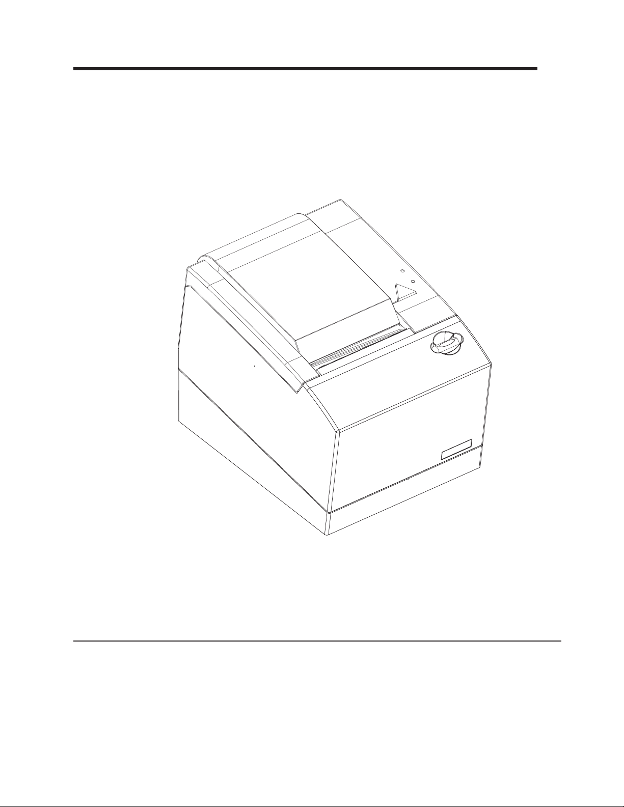
An interface card provides communication with the SureMark Models 1NR, 1NA,
and 1ND to the system unit. Select the card for your type of communication: the
RS-485, RS-232, USB, or Ethernet.
BA C D
Figure 2. USB interface card
A Cash drawer
B Powered USB
C Standard USB
D Power supply
E F G
Figure 3. RS-232 interface card
E Cash drawer
F RS-232
G Power supply
Chapter 1. Introducing the 4610 Models 1NR, 1NA, and 1ND 3
Page 22
H
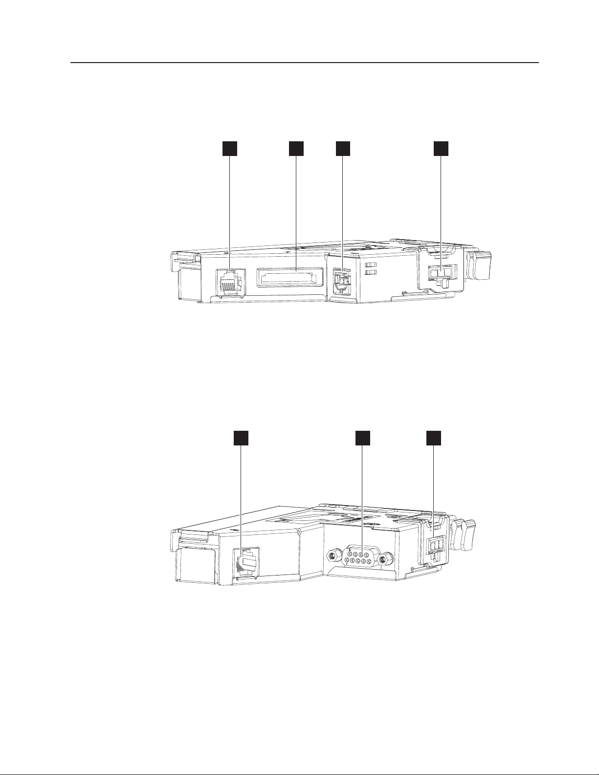
Figure 4. RS-485 interface card
I
H Cash drawer
I RS-485
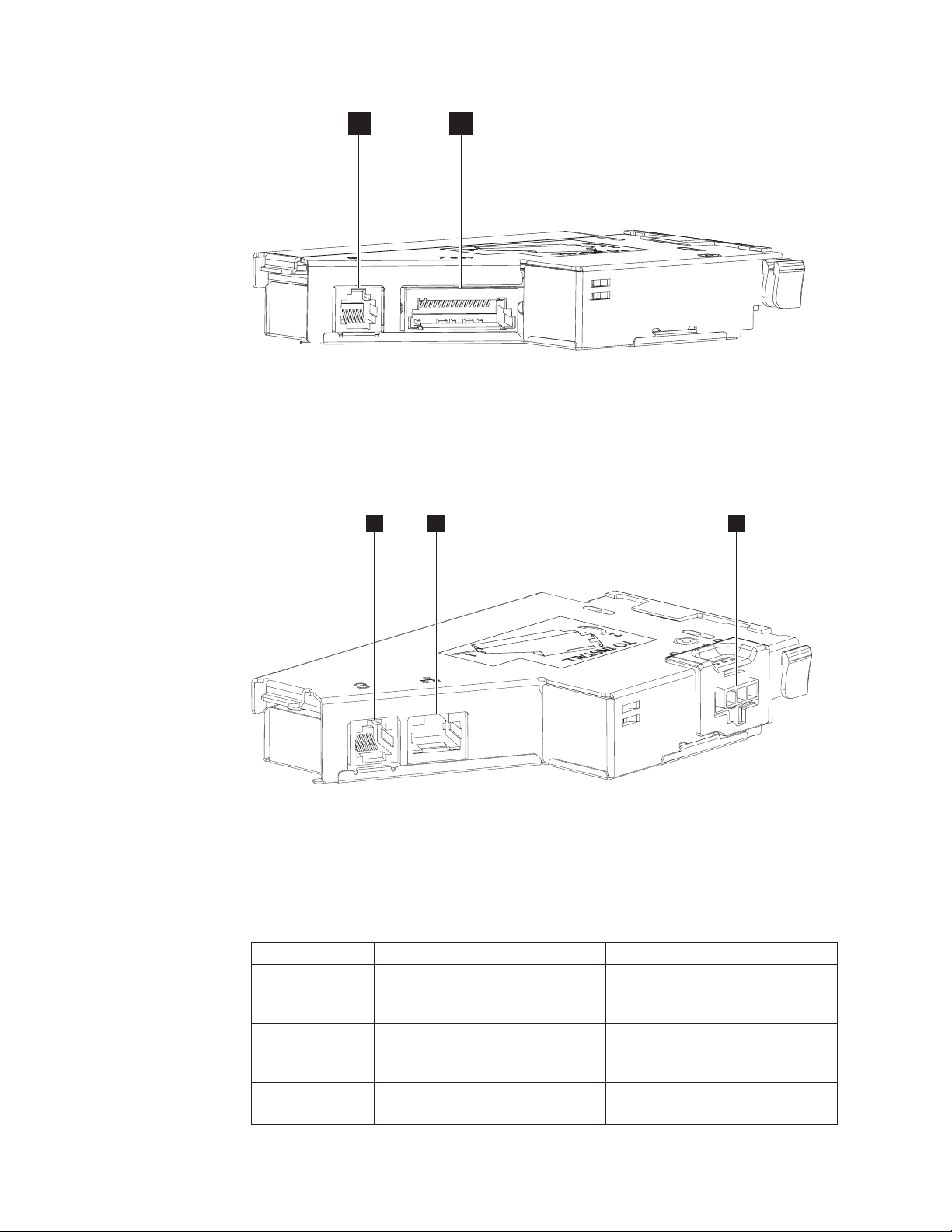
Figure 5 illustrates the communications connections on the Ethernet interface card.
|
J
|
|
Figure 5. Ethernet interface card
K
L
|
||
||
||
|
|
J Ethernet
K Power supply
L Cash drawer
Table 2. Communication interface, rate, and power source
Device Description Power
Ethernet 10/100 Ethernet port for connection
to an industry standard Ethernet
LAN
RS-232 9.6K-115.2 K (selectable using
offline or online configuration) baud
rate
RS-485 Toshiba proprietary System unit input voltage +38 V or
Requires separate power supply
Requires separate power supply
+24 V (Japan only)
4 SureMark Hardware Service
Page 23

Table 2. Communication interface, rate, and power source (continued)
Device Description Power
USB USB is 2.0-Compliant Full-Speed
HID; bulk transfers at 12 Mbps
(megabits per second)
System unit input voltage (+24 V);
power supply if standard USB
cable is used
Chapter 1. Introducing the 4610 Models 1NR, 1NA, and 1ND 5
Page 24

Ethernet Configuration
|
|
|
|
Ethernet communications are supported on printers manufactured after June 10,
2013, with firmware EC level 14.00 and above. The date of manufacture can be
found on the bottom of the printer.
|
|
|
|
|
|
|
|
|
|
|
|
|
|
|
|
|
|
|
|
|
Older levels of the main logic cards (MLC) for these printers manufactured prior to
June 10, 2013 will not support Ethernet. MLCs that have the circuitry to support
Ethernet will be identified internal to the card.
If an Ethernet Interface adapter is installed and the MLC indicates that Ethernet is
not supported, an error message is printed. On the 1xR printers, the ready light will
blink amber.
A media access control (MAC) address is necessary for Ethernet function and will
be stored in the Ethernet interface adapter at the factory. The printer will print out
an error message if the MAC address is invalid or is not stored in the Interface
card. There is no capability of changing or cloning a MAC address in the field.
Every interface card (IFC) has a unique MAC address. See “Toshiba Diagnostics for
the Ethernet Printer” on page 39 for more information.
If an Ethernet adapter is detected, the firmware will not back-level to a pre-Ethernet
supported level.
Ethernet addressing options can be changed via:
1. Offline menus: See “Firmware offline tests” on page 45 for more information.
Reset Network Configuration will reset the user-modifiable network configuration
items to factory default. MAC is not affected.
2. Web interface.
3. Configuration utility.
4. Web API configuration download.
|
|
|
|
|
|
|
|
|
|
|
|
|
|
|
|
|
|
|
When these options are changed, they are stored in the MLC (main logic card) and
backed up in the IFC (interface card). If the printer's IFC is replaced, the values will
be updated with the following logic:
v When an IFC does not have a valid serial number (a card from FRU stock), all
Ethernet options will be copied automatically from the MLC to the IFC.
v If an IFC has a valid serial number, but it is different from the printer's serial
number, a menu will print with the options of updating MLC or updating IFC.
Remarks:
v The MAC address in the IFC will never change.
v On the 1NR printer, the serial number of the printer will not be overwritten by the
serial number in the IFC.
v On the 2xR printer, the menu will ask which serial number is correct. The
Ethernet options will be updated along with the serial number and other stored
data.
Note: The exception to the logic above occurs when the IFC is setup as a slave
card. When the IFC is a slave card, the Ethernet options used will be those
pulled from the IFC.
Slave cards may be used by a depot or integrators to setup configurations or flash
the printer's firmware without changing any settings on the MLC before it is shipped.
6 SureMark Hardware Service
Page 25

|
|
Addressing
|
|
|
|
|
|
|
|
|
To make an IFC slave card:
v Store a serial number of 55-55555.
The printer supports standard Internet Protocol version 4 (IPv4) addressing. The IP
address and other IP network parameters are assigned using the following list of
priorities:
1. Fixed, if enabled and defined for the fixed IP selected.
2. Dynamic Host Configuration Protocol (DHCP), if the previous assignment
method does not apply and a DHCP server is available.
3. Auto IP, if neither of the previous assignment methods apply and Auto IP is
enabled.
|
|
|
|
||||
||||
||||
||||
||||
|||||
|
DHCP
|
|
|
|
|
|
|
|
|
||
||
||
||
||
|
When Fixed IP and Auto IP are disabled, the printer will wait for a valid DHCP
server.
Table 3. Provided ports
Port Protocol Service Comments
80 TCP HTTP
161 UDP SNMP Version 1 and 2 are supported.
162 TCP/UDP SNMP Trap
9100 UDP Printer Control Used for reservation and other control function.
TCP PDL Data
Stream
Used to send RAW printer data to a printer.
Dynamic Host Configuration Protocol (DHCP) is the default IP configuration method
(see “Addressing” on page 7 for more information). DHCP will be implemented
according to Request for Comments (RFC) 2131, Dynamic Host Configuration
Protocol, RFC 2132, DHCP Options and BOOTP Vendor Extensions, and applicable
updates. These specifications and applicable updates may be found at
http://datatracker.ietf.org/.
Table 4. Supported DHCP options
Tag Name
1 Subnet Mask
3 Router
6 Domain Name Server
12 Hostname
Auto IP
|
|
|
|
|
|
|
Auto IP is a method for a host to assign itself a Local Link IP address, described in
RFC 3927. The printer will randomly select an address from the range 169.254.1.0
to 169.254.254.255 and verify that it is not in use.
Auto IP can be disabled when the user determines that the printer should always
have a valid server. This will keep the printer from setting up an auto IP when the
server is temporarily unavailable.
Chapter 1. Introducing the 4610 Models 1NR, 1NA, and 1ND 7
Page 26

|
|
|
Systems management support with Ethernet - SNMP
|
Note: A printer may take two minutes or more to obtain an IP address via Auto IP
due to the DHCP server time-out and other required delays. Auto IP is
intended for initial printer setup when a DHCP server is not available.
Ethernet printers support Read Only Simple Network Management Protocol (SNMP)
for systems management. The printers support management information base II
(MIB II) for management of the Ethernet configuration (RFC 1213) and a private,
enterprise MIB for the 4610 printers. Any client can retrieve the MIB data from the
printer. The printer will also support up to two SNMP managers to receive SNMP
Traps on state changes in the printer and attached cash drawers.
SNMP is used to manage the printer, not the printing process. SNMP gathers
information about the state of the printer:
v Status: Information regarding the current operating state of the printer (offline / on
line / error conditions).
v Alert: The representation of a reportable event in the printer. An event is a
change in the state of the printer; sent as an SNMP trap.
SNMP contains support for retrieving data (Get and GetNext requests) and
receiving notification of change of state and error conditions via Alerts (or Traps) as
unsolicited messages to listening managers. Setting or changing a condition in the
printer (Set requests) is not supported via SNMP.
|
|
|
|
|||
||||
||||
||||
||||
|||
|||
|||
|||
|||
|||
Alerts
Clients can register to receive Traps on the following state changes in the printer:
Table 5. Printer state changes
Function Name Object Identifier (OID)
Cash Draw Open /
Closed
Magnetic
Interference MICR
CR cover Open /
Closed
DI Cover Open /
Closed
Paper Out receiptEmpty 1.3.6.1.4.1.1129.2.500.1.1.2.2
Paper Low NA 1.3.6.1.4.1.1129.2.500.1.3.2.2
Home Error NA 1.3.6.1.4.1.1129.2.500.1.3.2.3
Offline / Online NA 1.3.6.1.4.1.1129.2.500.1.3.2.6
Paper Jam NA 1.3.6.1.4.1.1129.2.500.1.3.2.5
Cutter Jam NA 1.3.6.1.4.1.1129.2.500.1.3.2.1
DrawerOpened 1.3.6.1.4.1.1129.2.500.1.1.3.1
MICR_CurrentMICRNoiseValue 1.3.6.1.4.1.1129.2.500.1.1.3.6
receiptCoverOpen 1.3.6.1.4.1.1129.2.500.1.1.2.1
NA 1.3.6.1.4.1.1129.2.500.1.3.2.4
|
|
|
Up to two SNMP managers can be enabled to receive these alerts. See Statistics
table entries for details on enabling these traps.
|
|
|
|
8 SureMark Hardware Service
4610 Private Enterprise MIB
The 4610 Private Enterprise management information base (MIB) is shown in
Table 6 on page 9. Get request to the printer will retrieve this data.
Note: The access type for all entries is Read Only.
Page 27

|
|
|||
|||
|||
|||
|||
|||
|||
Table 6. 4610 Private Enterprise MIB
Name Object Identifier (OID) Type
receiptStationPresent 1.3.6.1.4.1.1129.2.500.1.1.1.1 Integer
paperCutter 1.3.6.1.4.1.1129.2.500.1.1.1.2 Integer
coverSensor 1.3.6.1.4.1.1129.2.500.1.1.1.3 Integer
receiptEmptySensor 1.3.6.1.4.1.1129.2.500.1.1.1.4 Integer
nearEndSensor 1.3.6.1.4.1.1129.2.500.1.1.1.5 Integer
receiptPageMode 1.3.6.1.4.1.1129.2.500.1.1.1.6 Integer
|
|||
|||
|||
|||
|||
|||
|||
|||
|||
|||
|||
|||
|||
|||
|||
|||
|||
receiptCoverOpen 1.3.6.1.4.1.1129.2.500.1.1.2.1 Integer
receiptEmpty 1.3.6.1.4.1.1129.2.500.1.1.2.2 Integer
ThermalPrintHeadElementFailure 1.3.6.1.4.1.1129.2.500.1.1.2.3 Integer
receiptNearEnd 1.3.6.1.4.1.1129.2.500.1.1.2.4 Integer
receiptPaperRemaining 1.3.6.1.4.1.1129.2.500.1.1.2.5 Integer
receiptPaperJamCount 1.3.6.1.4.1.1129.2.500.1.1.2.6 Integer
receiptUnexpectedCoverOpenCount 1.3.6.1.4.1.1129.2.500.1.1.2.7 Integer
receiptPaperCutCount 1.3.6.1.4.1.1129.2.500.1.1.2.8 Integer
receiptCharactersPrintedCount 1.3.6.1.4.1.1129.2.500.1.1.2.9 Integer
receiptCoverOpenCount 1.3.6.1.4.1.1129.2.500.1.1.2.10 Integer
receiptLineFeedCount 1.3.6.1.4.1.1129.2.500.1.1.2.11 Integer
receiptFailedPaperCutCount 1.3.6.1.4.1.1129.2.500.1.1.2.12 Integer
writeCountNVRAM 1.3.6.1.4.1.1129.2.500.1.1.2.13 Integer
maximumTemperatureReachedCount 1.3.6.1.4.1.1129.2.500.1.1.2.14 Integer
receiptPrintHeadFailureCount 1.3.6.1.4.1.1129.2.500.1.1.2.15 Integer
flashWriteFailedCount 1.3.6.1.4.1.1129.2.500.1.1.2.16 Integer
barcodePrintedCount 1.3.6.1.4.1.1129.2.500.1.1.2.17 Integer
|
|||
|||
|||
|||
|||
|||
DrawerOpened 1.3.6.1.4.1.1129.2.500.1.1.3.1 Integer
DrawerGoodOpenCount 1.3.6.1.4.1.1129.2.500.1.1.3.2 Integer
DrawerFailedOpenCount 1.3.6.1.4.1.1129.2.500.1.1.3.3 Integer
MICR_GoodReadCount 1.3.6.1.4.1.1129.2.500.1.1.3.4 Integer
MICR_FailedReadCount 1.3.6.1.4.1.1129.2.500.1.1.3.5 Integer
MICR_CurrentMICRNoiseValue 1.3.6.1.4.1.1129.2.500.1.1.3.6 Integer
|
|||
|||
|||
slipStationPresent 1.3.6.1.4.1.1129.2.500.1.2.1.1 Integer
fullSlip 1.3.6.1.4.1.1129.2.500.1.2.1.2 Integer
bothSidesPrint 1.3.6.1.4.1.1129.2.500.1.2.1.3 Integer
|
|||
|||
|||
|||
ImpactHeadFailedCount 1.3.6.1.4.1.1129.2.500.1.2.2.1 Integer
PrintSideChangeCount 1.3.6.1.4.1.1129.2.500.1.2.2.2 Integer
FailedPrintSideChangeCount 1.3.6.1.4.1.1129.2.500.1.2.2.3 Integer
slipCharactersPrintedCount 1.3.6.1.4.1.1129.2.500.1.2.2.4 Integer
Chapter 1. Introducing the 4610 Models 1NR, 1NA, and 1ND 9
Page 28

|
|||
|||
|||
|||
|||
|||
|||
Table 6. 4610 Private Enterprise MIB (continued)
Name Object Identifier (OID) Type
slipCoverOpenCount 1.3.6.1.4.1.1129.2.500.1.2.2.5 Integer
slipLineFeedCount 1.3.6.1.4.1.1129.2.500.1.2.2.6 Integer
slipUnexpectedCoverOpenCount 1.3.6.1.4.1.1129.2.500.1.2.2.7 Integer
slipFeedErrorCount 1.3.6.1.4.1.1129.2.500.1.2.2.8 Integer
HomeErrorCount 1.3.6.1.4.1.1129.2.500.1.2.2.9 Integer
FormInsertionCount 1.3.6.1.4.1.1129.2.500.1.2.2.10 Integer
|
|||
|||
|||
|||
|||
|||
|||
|||
|||
|||
DeviceID 1.3.6.1.4.1.1129.2.500.1.3.1.1 String
PhysicalDeviceDescription 1.3.6.1.4.1.1129.2.500.1.3.1.2 String
PhysicalDeviceName 1.3.6.1.4.1.1129.2.500.1.3.1.3 String
Bus 1.3.6.1.4.1.1129.2.500.1.3.1.4 String
DeviceCategory 1.3.6.1.4.1.1129.2.500.1.3.1.5 String
FirmwareRevision 1.3.6.1.4.1.1129.2.500.1.3.1.6 String
ManufactureDate 1.3.6.1.4.1.1129.2.500.1.3.1.7 String
ManufacturerName 1.3.6.1.4.1.1129.2.500.1.3.1.8 String
ModelName 1.3.6.1.4.1.1129.2.500.1.3.1.9 String
SerialNumber 1.3.6.1.4.1.1129.2.500.1.3.1.10 String
|
|
|
|
|
|
|
|
|
|
|
|
|
|
|
|
|
|
|
HTTP Server
|
|
|
MIB II
Management information base II (MIB II) is used to convey information about the
TCP/IP configuration. The majority of the data that is recorded as part of MIB II will
not be useful in supporting the printer. For details, see the following information on
RFC 1213:
v Tree view of the RFC: http://www.snmplink.org/OnLineMIB/Standards/
v Full text: http://tools.ietf.org/html/rfc1213
The objects in MIB II are arranged in the following groups:
v System
v Interfaces
v Address Translation (deprecated)
v IP
v ICMP
v TCP
v UDP
v EGP
v Transmission
v SNMP
The printer provides an HTTP server for configuration, management, and diagnostic
functions.
10 SureMark Hardware Service
Page 29

Login and Overview
|
|
|
|
|
When a new HTTP connection is made, the printer prompts for a User Name and
Password. Completion of login establishes an active session which enables the
functionality as defined in the following sections. The logon screen varies depending
on the browser.
|
|
|
|
|
|
|
|
|
|
|
|
|
|
|
|
Web Pages
|
|
|
The default Username and Password are “Admin” and “Admin” respectively. These
may be redefined with the Web Interface in the HTTP Server, the Configuration
Utility, or the Web API configuration (see “Web API for printer configuration
management” on page 12).
The User Name and Password are limited to eight alphanumeric characters and are
case sensitive.
Data Display/Entry Fields
User Name:
Admin
v If an alternate login name is defined, the data entry field is blank;
otherwise, the default login name is displayed.
Password:
Admin
v The password is not displayed. A dummy character “*” is displayed for
each character entered.
The HTTP session remains active until the user logs off.
Once logged on, there are several pages in the printer that can be used for printer
management.
|
|
|
|
|
|
|
|
|
|
|
|
|
|
|
|
|
|
|
|
Overview:
Reports the printer’s serial number, model, firmware level, and the current
Ethernet setting.
Diagnostic:
Supports printing of an offline receipt, reports the user statistics of the
printer, and shows the current status of the printer.
Network:
Allows the user to change the current Network configuration.
SNMP:
Allows the user to set up the SNMP managers.
Admin Access:
Allows the user to change the Login and Password used for the HTTP
server.
System Update:
Allows the user to configure the printer and to download firmware, font, and
configuration files.
Reset:
Allows the user to reset the printer.
Logout:
Allows the user to log out of the printer.
Chapter 1. Introducing the 4610 Models 1NR, 1NA, and 1ND 11
Page 30

Web API for printer configuration management
|
|
|
|
|
|
|
|
|
|
|
The Managing Client can retrieve the printer’s configuration via an HTTP “Get”. The
printer will respond with a configuration file (see “Retrieving Printer’s configuration
using HTTP Server Get” on page 12). This file will include all necessary information
to determine the current printer configuration or setup:
v Firmware version
v Checksums of the various flash memory sectors:
– Fonts
– Character sets
– Messages
v Network settings
|
|
|
|
|
|
|
|
|
|
|
|
|
|
|
|
|
|
|
|
|
|
Knowledge of the printer specification and the locations of the given parameters are
required to interpret the output.
Once the manager determines that a printer requires updating, there are three file
types the printer will accept. These will come to the printer via HTTP POST:
1. Firmware file: The same firmware file that is supported by the drivers. *.hex
file.
The printer will verify the file format, validity (correct CRC), and version before
beginning the update process. Once verification is complete, it will program the
new firmware and reset. Following the reset, the printer will run at the new
firmware level.
2. Configuration file: Contains all the data the printer would need for
configuration in a given environment. This includes the network configuration.
3. Font file: The *.fon file that is supported by the UPOS drivers. See the UPOS
font support for creating this file with a configuration tool 4610cvnt.exe.
This file contains all the required data for setting up the font file in the printer. If
necessary, the printer will erase and then store all the font files and MCT values
associated with the font file. Example: If one of the DBCS font files is
downloaded, the printer will store the DBCS Impact, DBCS Thermal, SBCS
Impact User defined set 1, and SBCS Thermal User defined set 1, as well as
the MCTs needed to use these files by the printer and the UPOS drivers. If
required when downloading DBCS character sets, the printer will reset when the
font is done storing.
|
|
Retrieving Printer’s configuration using HTTP Server Get
|
|
|
|
|
Upon completion of setup, the printer will respond by sending a response to the
HTTP file.
The HTTP server Get is used for retrieving the configuration of the printer.
The HTTP header starts with get_Config:
GET /get_Config HTTP
12 SureMark Hardware Service
Page 31

|
|
Figure 6. Get Configuration header example
|
|
|
|
The format of the file sent back is the following:
<Configuration>
|
|
|
|
|
|
|
|
|
|
|
|
|
|
|
|
|
|
|
<serial_number>SSSSSSSS</serial_number>
<mac_address>MMMMMMMMMMMM</mac_address>
<ip4>xx.xx.xx.xx</ip4>
<firmware>xx.xx</firmware>
<devinfo>Printer ID</devinfo>
<mct><length><512></length><data>data</data></mct>
<stat>><length><512></length><data>data</data></stat>
<snmptrap1>databytes</snmpttrap1>
<snmptrap2>databytes</snmpttrap2>
<snmpmanager1>xx.xx.xx</snmpmanager1>
<snmpmanager2>xx.xx.xx</snmpmanager2>
<hostname>name</snmpmanager2>
<autoipenable>xxx</autoipenable>
<fixedipenable>xxx</fixedipenable>
<fixedipselected>fixedipselected</fixedipselected>
<ipv4fixedip>xx.xx.xx</ipv4fixedip>
<subnet>xx.xx.xx</subnet>
<gateway>xx.xx.xx</gateway>
|
|
</Configuration>
|
|
|
|
|
||
|
|
|
|
||
||
Where:
SSSSSSSS
Printer Serial Number; ASCII alphanumeric string.
MMMMMMMMMMMM
Printer’s MAC address; ASCII encoded HEX.
name ASCII String; max 12 characters.
xx.xx.xx Valid IP address
v snmpmanager1: IP address of the 1st client receiving SNMP alerts
v snmpmanager2: IP address of the 2nd client receiving SNMP alerts
v ipv4fixedip: User Defined Fixed IP
xx.xx ASCII encoded Hex number representing the EC level of the firmware.
xxx YES or NO.
Chapter 1. Introducing the 4610 Models 1NR, 1NA, and 1ND 13
Page 32

||
|
n Hex number for the slot number, MCT number or statistic number being
changed.
||
|
|
|
|
|
|
|
||
||
||
||
||
||
||
||
||
||
|
|
data Hex bytes.
v MCT: Two bytes for each location in the MCT table. The table is 256
locations of two bytes each. MCTs that are not defined are set as 0xffff.
v Stat: Two bytes for each location in the statistics table. The table is 256
locations of two bytes each. Statistics that are not defined are set as
0xffff.
databytes
Two hex bytes associated with the traps being set:
Bit 15 Cash Drawer Open / Closed
Bit 14 Magnetic Noise present (MICR read)
Bit 13 Paper Out
Bit 12 Paper Low
Bit 11 Home Error
Bit 10 Paper Jam
Bit 9 Cutter Jam
Bit 8 CR Cover Open / Closed
Bit 7 DI Cover Open / Closed
Bit 6 Hard Error at the printer (printer offline). MLC error / IFC error /
Firmware can not initialized motion sensor and/or thermal print
head.
|
|
|
|
||
||
||
|
|
||
||
||
||
||
||
||
||
Details:
snmptrap1:
Bits2-5
Reserved - should remain high
Bit 0, 1
Version option for returning Trap messages – SNMP manager 1:
11 Version 1
10 Version 2
01 Version 3 (Currently not supported)
Bit 15 Cash Drawer Open / Closed
Bit 14 Magnetic Noise present (MICR read)
Bit 13 Paper Out
Bit 12 Paper Low
Bit 11 Home Error
Bit 10 Paper Jam
Bit 9 Cutter Jam
Bit 8 CR Cover Open / Closed
||
14 SureMark Hardware Service
Bit 7 DI Cover Open / Closed
Page 33

||
|
|
Bit 6 Hard Error at the printer (printer offline). MLC error / IFC error /
Firmware can not initialized motion sensor and/or thermal print
head.
|
|
|
|
||
||
|
|
|
|
|
|
||
||
|
|
||
|
|
|
|
|
snmptrap2:
fip: fip: Hex byte
Bits2-5
Reserved - should remain high
Bit 0, 1
Version option for returning Trap messages – SNMP manager 1:
11 Version 1
10 Version 2
Default: 0xFF
Bits2-15
Reserved - should remain high
Bit 0, 1
Version option for returning Trap messages – SNMP manager 2:
11 Version 1
10 Version 2
Default:
0xFF
0x03 = User Configured Fixed IP Enabled (default) when there is a
fixed IP defined.
0x02 = Fixed IP Config 1 Enabled
0x01 = Fixed IP Config 2 Enabled
0x00 = Fixed IP Config 3 Enabled
|
|
|
|
|
HTTP Server POST
|
|
|
|
|
|
|
|
|
|
|
|
|
Default:
0xFF
ipv4fixedip
Valid IP address encoded as ASCII encoded Decimal that will return only
when User Configured Fixed IP is enabled and defined.
The HTTP server power-on self-test (POST) is used for updating firmware, sending
the font file, and sending the configuration file.
Firmware Upload:
v The HTTP header starts with upload after POST: POST /upload HTTP/.
v Content type is "multipart/form-data".
v Content-type: String needs to be at the end of header, beginning of data section.
v Response:
– On successful storing: Firmware file download complete.
– On any error with receiving or storing file: Invalid Firmware File.
Configuration Upload:
v The HTTP header starts /upload_Config after POST: POST /upload_Config
HTTP/.
Chapter 1. Introducing the 4610 Models 1NR, 1NA, and 1ND 15
Page 34

|
|
|
|
v Content type is "multipart/form-data".
v Response:
– On successful storing: Configuration Update completed.
– On any error with receiving or storing file: Invalid Configuration File.
|
|
|
|
|
|
|
|
Font Upload:
v The HTTP header starts /upload_Font after POST: POST /upload_Font HTTP/.
v Content type is "multipart/form-data".
v Response:
– On successful storing: Fonts download completed.
– On any error with receiving or storing file: Invalid Font File.
Example of Java Program for posting a file:
16 SureMark Hardware Service
Page 35

public static void main(String[] args) throws IOException {
|
|
|
|
|
|
|
|
|
|
|
|
|
|
|
|
|
|
|
|
|
|
|
|
|
|
|
|
|
|
|
uploadFile.getName() + "\";filename=\"" + "textFile" + "\"" + crlf).getBytes("UTF8"));
|
|
getBytes("UTF8"));
|
|
|
|
|
|
|
|
|
|
|
|
}
|
|
// takes file path from first program’s argument
String filePath = "C:\\ec12_0a.hex";
File uploadFile = new File(filePath);
System.out.println("File to upload: " + filePath);
// creates a HTTP connection
URL url = new URL(UPLOAD_URL);
HttpURLConnection httpConn = (HttpURLConnection) url.openConnection();
httpConn.setUseCaches(false);
httpConn.setDoOutput(true);
httpConn.setRequestMethod("POST");
httpConn.setRequestProperty("Content-type","multipart/form-data; boundary=" + boundary);
// sets file name as a HTTP header
httpConn.setRequestProperty("fileName", uploadFile.getName());
httpConn.connect(); // new.
// opens output stream of the HTTP connection for writing data
OutputStream outputStream = httpConn.getOutputStream();
// Opens input stream of the file for reading data
FileInputStream inputStream = new FileInputStream(uploadFile);
byte[] buffer = new byte[BUFFER_SIZE];
int bytesRead = -1;
System.out.println("Start writing data...");
outputStream.write((twoHyphens + boundary + crlf).getBytes("UTF8"));
outputStream.write(new String("Content-Disposition: form-data; name=\"" +
outputStream.write(new String("Content-Type: application/octet-stream\r\n\r\n").
while ((bytesRead = inputStream.read(buffer)) != -1) {
outputStream.write(buffer, 0, bytesRead);
}
outputStream.write(crlf.getBytes());
outputStream.write((twoHyphens + boundary + twoHyphens).getBytes());
System.out.println("Data was written.");
outputStream.close();
inputStream.close();
Configuration file format
|
|
|
|
|
|
<configuration>
<logo>
<erase>xxx</erase>
<slot><number>n</number><width>WW</width><height>HH</height><data>
databytes</data></slot>
Chapter 1. Introducing the 4610 Models 1NR, 1NA, and 1ND 17
Page 36

|
|
|
|
|
|
|
|
|
|
|
|
|
|
|
|
|
|
|
|
|
|
|
|
|
|
|
|
|
|
|
|
|
|
|
|
|
|
<slot><number>n</number><width>WW</width><height>HH</height><data>
databytes</data></slot>
.......
</logo>
<message>
<erase>xxx</erase>
<slot><number>n</number><length>LLLL</length>
<data>databytes</data></slot>
<slot><number>n</number><length>LLLL</length>
<data>databytes</data></slot>
.......
</message>
<mct>
<slot><number>n</number><data>databytes</data></slot>
<slot><number>n</number><data>databytes</data></slot>
.......
</mct>
<statistics>
<slot><number>n</number><data>databytes</data></slot>
<slot><number>n</number><data>databytes</data></slot>
.......
</statistics>
<network>
<snmptrap1>databytes</snmpttrap1>
<snmptrap2>databytes</snmpttrap2>
<snmpmanager1>xx.xx.xx</snmpmanager1>
<snmpmanager2>xx.xx.xx</snmpmanager2>
<httpuserid>name</httpuserid>
<httppw>password</httppw>
<hostname>name</hostname>
<autoipenable>xxx</autoipenable>
<fixedipenable>xxx</fixedipenable>
<fixedipselected>fip</fixedipselected>
<ipv4fixedip>xx.xx.xx</ipv4fixedip>
<subnet>xx.xx.xx</subnet>
<gateway>xx.xx.xx</gateway>
</network>
</configuration>
|
||
||
|
||
||
||
|
|
||
|
|
18 SureMark Hardware Service
Where:
xxx YES or NO
n Hex number for the slot number, MCT number, or Statistic number being
changed.
LLLL Length of the message data (ASCII representation of hex value).
WW Width of the logo (ASCII representation of hex value).
HH Height of the logo (ASCII representation of hex value).
xx.xx.xx
Valid IP address encoded as ASCII encoded Decimal.
name ASCII String, Max 12 characters.
databytes
Hex number for data associated with this change.
Page 37

|
|
|
|
|
||
|
|
|
||
||
||
||
||
||
||
||
||
||
|
|
Details:
MCTs and Statistics:
2 bytes for each MCT number or Statistics number. There are 256 values
for each: MCT and Statistic. Values not defined are set as 0xffff.
Logo: Logo data in hex, of length WW x HH x 8.
Message:
Hex data of message length is defined by LLLL.
snmptrap1:
Bit 15 Cash Drawer Open / Closed
Bit 14 Magnetic Noise present (MICR read)
Bit 13 Paper Out
Bit 12 Paper Low
Bit 11 Home Error
Bit 10 Paper Jam
Bit 9 Cutter Jam
Bit 8 CR Cover Open / Closed
Bit 7 DI Cover Open / Closed
Bit 6 Hard Error at the printer (printer offline). MLC error / IFC error /
Firmware can not initialized motion sensor and/or thermal print
head.
|
|
|
|
||
||
|
|
snmptrap2:
|
|
|
|
||
||
|
|
|
fixedipselected:
|
|
|
Bits2-5
Reserved - should remain high
Bit 0, 1
Version option for returning Trap messages – SNMP manager 1:
11 Version 1
10 Version 2
Default: 0xFF
Bits2-15
Reserved - should remain high
Bit 0, 1
Version option for returning Trap messages – SNMP manager 2:
11 Version 1
10 Version 2
Default:
0xFF
fip: Hex byte
0x03 = User Configured Fixed IP Enabled (default) when there is a
fixed IP defined. See on page 20.
Chapter 1. Introducing the 4610 Models 1NR, 1NA, and 1ND 19
Page 38

|
|
|
0x02 = Fixed IP Config 1 Enabled
0x01 = Fixed IP Config 2 Enabled
0x00 = Fixed IP Config 3 Enabled
|
|
|
|
|
|
|
|
|
|
|
|
|
|
|
|
|
|
|
ipv4fixedip
Configuration file examples
Example 1:
Default:
0xFF
Valid IP address encoded as ASCII encoded Decimal that will return only
when User Configured Fixed IP is enabled and defined.
fip: Hex byte
0x03 = User Configured Fixed IP Enabled (default) when there is a
fixed IP defined.
0x02 = Fixed IP Config 1 Enabled
0x01 = Fixed IP Config 2 Enabled
0x00 = Fixed IP Config 3 Enabled
To download these Predefined Messages:
v To Slot 16: abcdefghijklmnopqrstuvwxyz<linefeed>
v To Slot 02: <X'1B;2D;01'>
abcdefghijklmnopqrstuvwxyz<linefeed><X'1B;2d;00'>
|
Figure 7. The configuration file open in a hex editor
|
|
|
|
|
Example 2:
To downloada2x4logo to Slot 1:
20 SureMark Hardware Service
Page 39

|
|
Figure 8. The configuration file open in a hex editor
|
|
Printer sharing
|
|
|
|
|
The printer sharing protocol provides a means for multiple clients to share a printer,
with each being granted exclusive access during the time of usage. The protocol is
established with Toshiba supported drivers, which can be found on the Toshiba
Global Commerce Solutions support website at www.toshibagcs.com/support.
Locating the power button
The power button for the 4610 Models 1NR, 1NA, and 1ND is located under the
paper door (as shown in Figure 9 on page 22).
Chapter 1. Introducing the 4610 Models 1NR, 1NA, and 1ND 21
Page 40

A
Figure 9. Power button
Operating system requirements
|
|
|
This section describes the operating system requirements for your 4610 Model
1NR, 1NA or 1ND printer. You can download drivers from the Toshiba Global
Commerce Solutions support website at www.toshibagcs.com/support.
A compatibility mode is provided in the printers to enable use of existing drivers and
applications with only minor modifications. For native mode support, see the
following tables:
RS-232 Printer
Table 7 includes a description of native mode support for the RS-232 Printer.
Table 7. Native Mode Support - RS-232 Printer
JavaPOS
Operating
System
4690 Yes V5R2 and
|
Microsoft
Windows®XP
®
Drivers 1.9.6
or later
Yes Yes Yes
OPOS Drivers
1.9.6 or later
POS
Subsystem
1.9.6 or later
Windows
Native Drivers
(NWD) Direct IO Comments
V6R2*
22 SureMark Hardware Service
Page 41

Table 7. Native Mode Support - RS-232 Printer (continued)
JavaPOS
Operating
System
Microsoft
Windows
Embedded for
Point of
Service
(WEPOS) 1.11
Microsoft
Windows
Embedded
POSReady
2009
|
Microsoft
|
Windows
|
Embedded
|
POSReady 7
Microsoft
Windows 7
(Professional/
Ultimate)
SUSE Linux
Enterprise
Desktop
(SLED) 11
SUSE Linux
Enterprise
Server (SLES)
11
SUSE Linux
Enterprise
Point of
Service
(SLEPOS) 11
PC DOS 2000 Yes
Drivers 1.9.6
or later
Yes Yes Yes Yes
Yes Yes Yes Yes
Yes Yes Yes Yes
Yes Yes Yes Yes
®
Yes Yes
Yes Yes
Yes Yes
OPOS Drivers
1.9.6 or later
POS
Subsystem
1.9.6 or later
Windows
Native Drivers
(NWD) Direct IO Comments
RS-485 Printer
Note: *The 2NR/2CR printers are supported in compatibility mode in V5R2 but
4690 OS can only update the firmware starting with the 0820 maintenance
package. The 1NR is supported in compatibility mode in V5R2 but requires
package 0900 for firmware update. All of these models are supported in
compatibility or native mode in V6R2.
Table 8 on page 24 includes a description of native mode support for the RS-485
Printer.
Chapter 1. Introducing the 4610 Models 1NR, 1NA, and 1ND 23
Page 42

Table 8. Native Mode Support - RS-485 Printer
Windows
JavaPOS
Drivers 1.9.6
Operating System
|
4690 V5R2 and
Microsoft Windows XP Yes Yes
Microsoft Windows
Embedded for Point of
Service (WEPOS) 1.11
Microsoft Windows
Embedded POSReady
2009
|
Microsoft Windows
|
Embedded POSReady
|
7
Microsoft Windows 7
(Professional/Ultimate)
SUSE Linux Enterprise
Desktop (SLED) 11
SUSE Linux Enterprise
Server (SLES) 11
SUSE Linux Enterprise
Point of Service
(SLEPOS) 11
PC DOS 2000 Not
or later
Yes Yes
Yes Yes
Yes Yes
Yes Yes
Yes Yes
Yes Yes
Yes Yes
OPOS
Drivers 1.9.6
or later
POS
Subsystem
1.9.6 or later
Native
Drivers
(NWD) Direct IO Comments
V6R2*
supported
Note: *The 2NR/2CR printers are supported in compatibility mode in V5R2 but
4690 OS can only update the firmware starting with the 0820 maintenance
package. The 1NR is supported in compatibility mode in V5R2 but requires
package 0900 for firmware update. All of these models are supported in
compatibility or native mode in V6R2.
24 SureMark Hardware Service
Page 43

USB Printer
Table 9 includes a description of native mode support for the USB Printer.
Table 9. Native Mode Support - USB Printer
Windows
JavaPOS
Drivers 1.9.6
Operating System
|
4690 V5R2 and
Microsoft Windows XP Yes Yes Yes
Microsoft Windows
Embedded for Point of
Service (WEPOS) 1.11
Microsoft Windows
Embedded POSReady
2009
|
Microsoft Windows
|
Embedded POSReady
|
7
Microsoft Windows 7
(Professional/Ultimate)
SUSE Linux Enterprise
Desktop (SLED) 11
SUSE Linux Enterprise
Server (SLES) 11
SUSE Linux Enterprise
Point of Service
(SLEPOS) 11
PC DOS 2000 Not
or later
Yes Yes Yes
Yes Yes Yes
Yes Yes Yes
Yes Yes Yes
Yes Yes
Yes Yes
Yes Yes
OPOS
Drivers 1.9.6
or later
POS
Subsystem
1.9.6 or later
Native
Drivers
(NWD) Direct IO Comments
V6R2*
supported
Ethernet Printer
|
|
|
Table 10. Native Mode Support - Ethernet Printer
|
|
|
Operating System
|||||
||
4690 Not supported
|||||
Microsoft Windows XP Yes Yes
|||||
Microsoft Windows Embedded for
||||||
Point of Service (WEPOS) 1.11
Microsoft Windows Embedded
||||||
POSReady 2009
||||||
Microsoft Windows Embedded
POSReady 7
||||||
Microsoft Windows 7
(Professional/Ultimate)
Table 10 includes a description of native mode support for the Ethernet Printer.
Windows Native
JavaPOS Drivers
1.13.5 or later
Yes Ye s Yes
Yes Ye s Yes
Yes Ye s Yes
Yes Ye s Yes
OPOS Drivers
1.13.5 or later
Chapter 1. Introducing the 4610 Models 1NR, 1NA, and 1ND 25
Drivers (NWD)
3.1.0 or later Comments
Page 44

Table 10. Native Mode Support - Ethernet Printer (continued)
|
|
|
|||||
||
Operating System
||||||
SUSE Linux Enterprise Desktop
(SLED) 11 Service Pack 3
||||||
SUSE Linux Enterprise Server
(SLES) 11 Service Pack 3
|
||||
SUSE Linux Enterprise Point of
|
Service (SLEPOS) 11 Service
|
Pack 3
|||||
PC DOS 2000 Not supported
JavaPOS Drivers
1.13.5 or later
Yes
Yes
Yes
OPOS Drivers
1.13.5 or later
Windows Native
Drivers (NWD)
3.1.0 or later Comments
|
|
Hardware requirements
SureMark printers work with the following systems:
|
|
|
|
|
|
v 4694 systems
v 4695 systems (RS-232 connection only and with power supply)
v PC or other store controller with an RS-232, USB, or Ethernet port
v SurePOS
™
100 Series systems
v SurePOS 300 Series systems
v SurePOS 500 Series systems
v SurePOS 700 Series systems
v Self Checkout solution
v AnyPlace
v TCx
™
™
Wave
Kiosk
Calling for service
Before calling for service, you will need the machine type, model number, and serial
number of the printer This information can be found on the two printer information
labels. See “Printer information label” for the location of the two printer information
labels.
Printer information label
The printer information labels are located beside the power button on the inside of
the printer and on the front right edge of the main cover (see Figure 10 on page
27).
26 SureMark Hardware Service
Page 45

Printer
Information
Label
Figure 10. Location of label with machine type, model number and serial number
Chapter 1. Introducing the 4610 Models 1NR, 1NA, and 1ND 27
Page 46

28 SureMark Hardware Service
Page 47

Chapter 2. Product specifications
This section describes the physical specifications for models 1NR, 1NA, and 1ND.
Physical dimensions
Figure 11 describes the physical dimensions.
159 mm
(6.26 in)
177 mm
(6.97 in)
Figure 11. SureMark 4610 Models 1NR, 1NA, and 1ND dimensions
Table 11. Summary of dimensions
Width: 145 mm (5.71 in.) footprint
Height: Cover closed: 159 mm (6.26 in.)
Cover open: 260 mm (10.24 in.)
Depth: 177 mm (6.97 in.)
Weight: 1.4 kg (3.09 lb)
Temperature and humidity limits
Shipping -40° to 60° C (-40° to 140° F) with 5% to 100% relative humidity
including condensation, but excluding rain
Storage 0° to 60° C (32° to 140° F) with 5% to 80% relative humidity
145 mm
(5.71 in)
Operating 5° to 40° C (42.8° to 104° F) with 8% to 80% relative humidity
29
Page 48

Connector pin assignments
The following sections describe the connector pin assignments for the external
connectors
Power supply
Table 12. Power supply pin designations
Pin Signal
1 +24Vdc
2 Not connected
3 Ground
USB
Table 13. USB pin designations
Pin Signal
1 Vbus (+5 V dc)
2 Minus data
3 Plus data
4 Ground
Powered USB
RS-232
Table 14. Powered USB pin designations
Pin Signal
1 Ground (+24 V dc)
2 (+24 V dc)
3 Ground (Vbus)
4 Plus data
5 Minus data
6 Vbus +5 V dc
7 +24Vdc
8 Ground (+24 V dc)
Table 15. RS-232 pin designations
Pin Signal
1 Not connected
2 Transmit
3 Receive
4 DTR
5 Signal ground
6 DSR
30 SureMark Hardware Service
Page 49

RS-485
Table 15. RS-232 pin designations (continued)
Pin Signal
7 Not connected
8RTS
9 Not connected
Table 16. RS-485 pin designations. Note: The 24 V version is available in Japan; all 38 V
DC's change to 24 V DC for that card.
Pin Signal
1 +5Vdc
2 Ground (5 V dc)
3 +5Vdc
4 Ground (5 V dc)
5 +5Vdc
6 Ground (5 V dc)
7 Data "B"
8 Data "A"
9 Ground (38 V dc)
10 +38 V dc
11 Ground (38 V dc)
12 +38 V dc
13 Ground (38 V dc)
14 +38 V dc
15 Ground (38 V dc)
16 +38 V dc
Chapter 2. Product specifications 31
Page 50

Cash drawer
A single connector can drive either a single cash drawer or two cash drawers using
a special cable. The connector provides a status line if one of the cash drawers is
open. The cash drawer cannot be activated while the printer is operating.
Table 17. Cash drawer connector pin designations
Pin Signal
1 Not connected
2 Solenoid 1 drawer
3 Cash drawer status
4 +24Vdc
5 Solenoid 2 drawer
6 Ground
Printing width, speed, and acoustics
Table 18. Station characteristics
Characteristic Customer receipt station
Speed (see note
following table)
Paper Width 58 mm or 80 mm
Print Width 34 characters at 12 cpi
Pitch 12, 15, 17, 20 cpi
Up to 80 lps thermal (one-color)
44 characters at 15 cpi
48 characters at 17 cpi
57 characters at 20 cpi
Note: To ensure reliable operation, the printer reduces throughput when printing
higher densities or continuous (no pause) paper feeding. This might affect
overall throughput. Optimize print density to maximum throughput.
The reduced print speed is based on the number of print dots that are turned
on for a given print line, which is defined as dot utilization. Dot utilization
typically is low for normal character printing and up to 100% for full black line
printing. The SureMark printer operates at 80 lps at low dot utilization, and at
slower speeds as the dot utilization increases. It is also controlled by receipt
motor use.
Table 19. Sound characteristics
Type Description LwAd LpAm <LpA>m
Operating
(bels)
SureMark Printer 5.7 N/A 61.5 N/A 47 N/A
Idling (bels) Operating
(dB)
Idling (dB) Operating
(dB)
Idling (dB)
Notes:
LwAd The declared upper limit of the sound power level for a random
sample of machines.
32 SureMark Hardware Service
Page 51

Bar codes
LpAm The mean value of the A-weighted sound pressure levels at the
operator position (if any) for a random sample of machines.
<LpA>m
The mean value of the A-weighted sound pressure levels at the
one-meter (bystander) positions for a random sample of machines.
N/A Indicates not applicable.
All measurements were made in accordance with ISO 7779 and reported in
conformance with ISO 9296.
SureMark printers can generate these bar codes:
v QR
v UPC A/E
v JAN 8 (EAN)
v Code 39
v ITF
v Code 93
v Code 128 A, B, C
v Codabar
v PDF417
Resident code pages
These code pages are resident in the printer:
v 437-US
v 858 - International
v 860 - Portuguese
v 863 - Canadian French
v 865 - Norwegian
v 869 - Greek
v 857 - Turkish
v 864 - Arabic
v 867 - Hebrew (Israel)
v 852 - Hungarian, Polish, Czech, Romanian, Slovak, Slovenian, Croatian
v 848 - Ukranian
v 866 - Russian (Cyrillic)
v 872 - Bulgarian, Serbian
v 775 - Lithuanian, Latvian, Estonia
v 861 - Icelandic
v 1250 - Windows Latin 2
v 1251 - Windows Cyrillic
v 1252 - Windows Latin 1
v 1253 - Windows Greek
v 1254 - Windows Turkish
v 1255 - Windows Hebrew
v 1256 - Windows Arabic
v 1257 - Windows Baltic Rim
These code pages may be downloaded to the printer:
v 932 - Japan
v 949 - Korea
v 950 - Traditional Chinese
v 1381 - Simplified Chinese
Chapter 2. Product specifications 33
Page 52

The firmware supports the following in the thermal station:
v Proportional fonts
v Scalable fonts
v Color printing: black plus one accent on two-color thermal paper (thermal station
only)
v Upside-down printing
v Watermark printing
34 SureMark Hardware Service
Page 53

Chapter 3. Adjusting and maintaining the 4610
To keep your 4610 Models 1NR, 1NA, and 1ND printers working properly, you
should periodically make printer adjustments and follow recommended maintenance
procedures. This section provides instructions on using, adjusting, and maintaining
your printer, and includes the following topics:
v Replenishing printer supplies
v Cleaning recommendations
For detailed technical information on the 4610 Models 1NR, 1NA, and 1ND printers,
see Chapter 2, “Product specifications,” on page 29.
|
|
Attention: All covers must be installed on the SureMark 4610 Models 1NR, 1NA,
and 1ND printer before and during operation.
Using and maintaining the 4610
Replenishing consumable supplies
You are responsible for replenishing the supply roll paper.
Loading and replacing the paper roll
Ensure that you have the correct paper for the 4610. See “Supported thermal
paper” on page 36.
1. Press and release the blue release button to release the paper door. In a
wall-mount configuration, you must also pull the door fully open, because of the
brake feature that decelerates it from the full force of gravity.
2. If necessary, remove any unused paper or the empty paper roll core before
inserting a new paper roll.
Note: Refer to the label inside the printer for a diagram of how to load paper.
3. Place the paper roll into the paper roll bucket as shown on the diagram. The
leading edge of the paper should come from the bottom of the roll as shown in
the diagram.
Note: The thermal printhead will not print on paper with glue on it. If the new
paper roll was sealed by glue, tear off the 6 to 8 inches of paper with
glue on it before loading it.
4. Close the paper cover.
5. Press the customer receipt feed button to advance the paper, to verify that the
paper is feeding correctly. Feed 30 cm (about 1 ft) of paper through to test for
correct alignment.
Attention: Do not pull the receipt paper out of the printer with the paper access
cover closed. This disengages the paper feed. The paper feed motor must then
catch up before the printer can feed the paper, which causes missing lines or partial
lines of print. Use the customer receipt feed button to advance the receipt and all
lines will print.
35
Page 54

Supported thermal paper
Attention: Using an inferior grade of paper can affect print quality as well as the
life of printheads and the printer mechanism.
Note: When selecting a paper, ensure that the paper's archive life meets the
requirements of the tax authorities of your country for archiving tax-related
data.
The paper used in the thermal receipt station must meet the following requirements:
Width 79.5 ± 0.5 mm (3.13 ± 0.02 in.) or 57.5 ± 0.5 mm (2.26 ± 0.02 in.)
Outside Diameter
102 mm (4.0 in.) maximum
Thickness
60 µm (0.00225 in.) optimal. Range: 41 µm minimum to 99 µm maximum.
Important
Paper has a significant manufacturing tolerance, and nominal paper
designations do not reflect actual measurements. The manufacturing
tolerance must fall within the published operating thickness range.
Customers should test paper in their specific configuration before use.
The intent of this specification is that if any spot measurement of the
paper is outside the specified range, the paper is deemed not to meet
the specification and the customer is responsible for any problems
caused by paper jams.
The paper must be wound with the printing side facing out. The paper should not
be attached to the core in any manner.
Important
Printer reliability and performance are directly related to the quality of the
supplies used by the customer. The published parameters for printer
performance are established using supplies that meet the specifications listed
above.
|
|
|
|
|
|
|
|
|
Thermal paper with watermarks, coupons, or advertisements printed on the
front or back of the paper is not covered by Toshiba specifications. Some
inks and printing processes work acceptably, but others do not. Printer
problems that are caused by supplies that do not meet Toshiba specifications
might result in a billable service call, regardless of the existence of a service
contract.
For supported papers, refer to the OEM Thermal Paper Testing table found under
SureMark Printers on the Toshiba Global Commerce Solutions support website:
www.toshibagcs.com/support.
Installing large paper rolls
|
|
|
The 4610 can accommodate extra-large rolls (up to 15 in.) of paper below the
printer. Mounting hardware is necessary to avoid placing undue strain on the paper
feed motor. See your Toshiba representative for additional information.
36 SureMark Hardware Service
Page 55

Cleaning recommendations
You should inspect your 4610 unit periodically and clean the cover as required. Use
a soft, clean cloth with warm, soapy water to clean the plastic parts. Do not use
abrasives or any alkaline, ammonia, or chloride-based cleaner.
Note: Do not apply cleaning solution directly to the cover. Always apply the cleaner
to a clean cloth and then wipe the cover with the damp cloth. Be certain that
the cloth is only damp and not dripping wet.
Cleaning the thermal printhead
|
|
|
|
|
The thermal printhead should be cleaned at regular intervals or when the print
quality has noticeably deteriorated. There are many factors that affect cleaning
frequency. Poor paper quality, high printer usage, or a dirty environment are all
reasons to clean the thermal printhead more often. Complete the following steps to
clean the thermal printhead:
1. Open the paper cover.
2. Using a cotton swab soaked in isopropyl alcohol, gently wipe the printhead
several times on its print line and on the surrounding area.
3. Wipe off any residual alcohol with a dry swab.
If print quality does not improve after cleaning the thermal printhead, run the
Thermal Printhead Health Test. If print quality still does not improve, call for service.
Chapter 3. Adjusting and maintaining the 4610 37
Page 56

38 SureMark Hardware Service
Page 57

Chapter 4. Running tests and diagnostics
|
|
|
|
Toshiba Diagnostics for POS Systems and Peripherals
|
|
|
|
|
|
|
|
|
|
Toshiba Diagnostics for the Ethernet Printer
|
|
|
|
|
|
|
|
|
|
|
|
|
|
|
|
|
|
|
|
|
|
|
|
|
|
|
|
This chapter describes the diagnostics tools, offline tests, and troubleshooting
procedures for the SureMark 4610 Models 1NR, 1NA, and 1ND printers.
Attention: For firmware and driver updates, refer to SureMark 4610 Printers:
Programming Guide for Models 1xR and 2xR, GA27-5005.
The Toshiba Diagnostics for POS Systems and Peripherals package, available from
the Toshiba Global Commerce Solutions support website, can be used for
diagnosing problems with the printer and for configuring and maintaining the printer
using included utilities. The website contains information on downloading and
installing the package.
The diagnostic package provides tests for the various components and functions of
the printer. It also provides utilities to load printer firmware, logos, messages, and
fonts as well as utilities for configuring the printer. These are found by clicking the
POS I/O Devices and Utilities buttons on the main selection panel.
The Toshiba Diagnostics package can be used with an Ethernet printer by following
these instructions:
1. Disconnect the printer from the store LAN.
2. Connect the printer to a laptop containing the diagnostics package. It may be
necessary to have your own LAN cable to connect the printer to the laptop.
3. Insert the Toshiba Diagnostics memory key into a USB port on the laptop.
v The printer should already have power from a power brick when the
Ethernet card is in the printer.
4. Prepare the printer for a diagnostics session by performing these steps:
a. Open the paper cover on the printer.
b. Press the power button to power the printer off and on again.
c. Close the paper cover.
d. Press and hold the paper feed button while the printer is powering up.
e. The Offline Selection Menu is printed.
f. Select Choose Emulation Mode....2 by pressing the paper feed button
twice and holding down the same button on the third time.
g. The Emulation Mode menu is printed. The printer should be in native mode
at this point.
h. Select Diagnostics Mode....1 by pressing paper feed button once and
holding down the same button on the second time. This mode will only be
seen if the printer has the Ethernet card in the printer.
i. When finished, exit the Offline Menu by pressing the paper feed button
once.
5. Boot the laptop with the Diagnostics key inserted.
6. In Toshiba Diagnostics, select either POS I/O Devices or Utilities.
7. Click the ADD DEVICE button at the bottom of the screen.
8. Select ADD A NETWORK PRINTER and follow the instructions.
39
Page 58

|
|
|
|
9. Toshiba Diagnostics will restart the Diagnostics application and display the
main Diagnostics screen again.
10. Perform the necessary Diagnostics activities. When complete, click the
SHUTDOWN button at the top right of the screen.
|
|
|
|
|
|
|
|
|
|
|
|
|
|
|
|
Situations of Importance for the Ethernet Printer
|
|
|
|
|
Note: You must shutdown the Diagnostics for the printer to be returned to the
retailer’s LAN configuration. This process will take 30 seconds or longer.
11. If you do not shutdown the Diagnostics, you must perform these steps:
a. Power off the printer.
b. Power the printer on and hold down the paper feed button to display the
Offline Menu on the cash receipt station.
c. Select Choose Emulation Mode....2 by pressing the paper feed button
twice and holding down the same button on the third time.
d. The Emulation Mode menu is printed. If the printed menu shows the printer
is in Diagnostics Mode, select the Diagnostics Mode....1 by pressing the
paper feed button once and holding down the same button on the second
time.
e. When finished, exit the Offline Menu by pressing the paper feed button
once.
12. Disconnect the printer from the laptop.
13. Connect the printer to the retailer's network.
Situation 1:
Printer issues when the retailer attempted a printer firmware update that
failed due to power outage or LAN outage; the retailer called Toshiba Global
Commerce Solutions for service.
|
|
|
|
|
|
|
|
|
|
|
|
|
|
|
|
|
|
|
|
|
Situation 2
This situation may imply that the printer is operating out of its backup boot
sector, which is an emergency environment to perform only firmware
update. Determine if this is the case by attempting to use the Offline Menu
on the printer. If the printer is operating out of its backup boot sector, there
will not be an Offline Menu printed on the cash receipt station.
The first suggestion to make to the retailer is for the retailer to run the
printer firmware update again that they previously attempted. This should
work the majority of the time.
If retrying the printer firmware update a second time does not resolve the
problem, replace the logic card in the printer.
Printer issues when attempting to update printer firmware using Toshiba
Diagnostics that failed due to power outage or LAN outage.
This situation implies that the printer is operating out of its backup boot
sector, which is an emergency environment to perform only firmware
update. Determine if this is the case by attempting to use the Offline Menu
on the printer. If the printer was booted from its backup boot sector, there
will not be an Offline Menu printed on the cash receipt station.
If this occurs, boot Toshiba Diagnostics with the Ethernet-attached printer
connected to the laptop again. Go through the Add Device process to add a
device, and then perform the printer firmware update again.
40 SureMark Hardware Service
Page 59

|
|
|
|
|
This action is possible because the printer retains the last known printer
configuration prior to the power or LAN outage and uses that configuration
when the printer is booted again. In this case, the printer was already in
Diagnostics Mode prior to the outage, so it will still be in Diagnostics Mode
when booted again.
|
|
|
|
Situation 3
|
|
|
|
|
Note: Be sure to follow the instructions for ending the printer diagnostics
session when you are finished using the Toshiba Diagnostics for that
printer.
The Ethernet POS printer prints a message on the cash receipt station
stating that the printer does not have a MAC address. You might receive
one of these messages:
Message 1:
Need a valid MAC address for Ethernet communications.
|
|
|
|
|
|
|
|
|
|
|
|
|
|
|
Message 2:
Card does not have a valid MAC address.
Printer will run in Diagnostic mode.
Fixed IP 1: 169.254.0.95
mask: 255.255.0.0
The Toshiba Diagnostics for POS Systems and Peripherals Version 6.2.1 or
later contains a utility that can correct this situation.
Before you begin:
v Write down the MAC address, which is located on the Ethernet card
attached to the underside of the printer. The printing on the Ethernet card
should appear in this way: MAC: 6CAE8B46xxxx.
v The Ethernet printer must have printer firmware level 15.03 or higher
installed. If the correct printer firmware level is not installed, it must be
updated.
|
|
|
|
|
|
|
|
|
|
|
|
|
|
|
|
|
|
Note: If Message 1 is received, firmware level 15.03 or higher is not yet
installed.
v To update the printer firmware when the printer is in this state, another
interface (USB, RS485, or RS-232) must be used in the printer. The
Toshiba Diagnostics package can be used to update the printer firmware.
Once the firmware is updated to level 15.03, put the Ethernet card back
in the printer and proceed with the rest of the instructions.
Follow these steps to put a MAC address into an Ethernet attached printer:
1. Connect the printer directly to your laptop or to the POS system unit
with an Ethernet cable. It may be necessary to have your own LAN
cable to connect the printer to the laptop.
2. Insert the TGCS Diagnostics Ver 6.2.1 or later memory key into one of
your system's USB ports. The printer should already have power from
a power brick when the Ethernet card is in the printer.
3. Boot the system to which the printer is attached.
4. When the printer powers on, a message is shown about not having a
MAC address. The printer is already in Diagnostics Mode at this point.
5. Navigate to the UTILITIES screen.
Chapter 4. Running tests and diagnostics 41
Page 60

|
|
|
|
|
|
|
|
|
|
|
|
6. Select the option to ADD DEVICE and then choose ADD A
NETWORK PRINTER. Follow the instructions. TGCS Diagnostics will
restart the Diagnostics application and the main Diagnostics screen will
appear again.
7. Navigate to the UTILITIES screen.
8. Printer utilities are visible on this screen as a PRINTER UPDATES
button. Choose PRINTER UPDATES and then select PRINTER
CONFIG.
9. Select MAC ADDRESS CONFIGURATION.
10. Enter the MAC address that you wrote down from the printer's
Ethernet card twice (two different fields). You will be prompted to verify
the MAC address before it is applied to the printer.
|
|
|
|
|
|
|
|
|
Toshiba Diagnostics for the RS-232 Printer
|
|
|
|
|
|
|
|
|
|
|
|
|
The Toshiba Diagnostics package can be used with an RS-232 printer by following
these instructions:
1. Insert the Toshiba Diagnostics memory key into a USB port on the system unit
to which the printer is connected.
2. Boot the laptop with the Diagnostics key inserted.
3. In Toshiba Diagnostics, select either POS I/O Devices or Utilities.
4. Click the ADD DEVICE button at the bottom of the screen.
5. Select ADD A RS-232 PRINTER and follow the instructions.
6. Toshiba Diagnostics will restart the Diagnostics application and display the main
Diagnostics screen again.
7. Perform the necessary Diagnostics activities. When complete, click the
SHUTDOWN button at the top right of the screen.
Note: The MAC address can only be set one time, so it must be the
correct address for the printer.
11. If there are any other printer activities that must be performed (running
tests, loading firmware, configuring the printer), do them at this time.
12. Shut down TGCS Diagnostics by clicking the SHUTDOWN button on
the top right side of the panel. It is important to shut down, because
this action takes the printer out of Diagnostics Mode when it next
powers on.
Toshiba Diagnostics for the USB or RS-485 Printer
|
|
|
|
|
|
|
|
|
The Toshiba Diagnostics package can be used with an RS-232 printer by following
these instructions:
1. Insert the Toshiba Diagnostics memory key into a USB port on the system unit
to which the printer is connected.
2. Boot the laptop with the Diagnostics key inserted.
3. In Toshiba Diagnostics, select either POS I/O Devices or Utilities.
4. Perform the necessary Diagnostics activities. When complete, click the
SHUTDOWN button at the top right of the screen.
42 SureMark Hardware Service
Page 61

Testing the 4610
When you switch on the SureMark printer, it runs a power-on self-test (POST). If
the POST finds no errors, the printer is ready for operation. Follow these steps if
you receive an error:
1. If the printer is turned on, turn off the printer and turn it on again.
v If the printer is attached to the system with the RS-232 cable or the standard
USB cable with a power brick, disconnect the power cord and then reconnect
the power cord to a properly wired and grounded power source.
v If the printer is attached to the system with the RS-485 cable, turn off the
POS system then switch on the system, which also powers on the printer.
v If the printer is attached to the system with a powered USB cable, the USB
attached printer can be hot-plugged.
2. Check the status of the printer-ready indicator:
v Printer-ready indicator ON: The POST completed successfully.
v Printer-ready indicator OFF or blinking: The POST failed.
3. If the POST fails or if you suspect problems with your system, see
“Troubleshooting” on page 49.
4. See “Firmware offline tests” on page 45 and run the offline tests. If the offline
tests fail or you suspect problems with your system, see “Troubleshooting” on
page 49.
Low paper sensing and calibration
Low-paper sensing in the Models 1NR, 1NA, and 1ND is based upon the paper
thickness and the core size. You can modify the low-paper and critically low sensing
settings. These settings determine the amount of paper that remains on the roll and
at which time the low-paper and the critically low-paper status is sent. The default
setting for low-paper status is 5 meters (or 5000 mm) remaining on the roll, and
critically low status is 1 meter (or 1000 mm) remaining on the roll.
Note: Prior to turning off the printer, send a reset command to the printer. If you
turn off the printer without a reset command, when you turn the printer back
on, it will start counting motor steps from the number stored in the printer's
memory. This will not be an accurate number if the printer was not able to
store the number with a reset command.
The low-paper sensor is customer-selectable for table or wall mount, depending on
application. The printer comes from the factory already in table mount mode. For
wall mount applications, you must move the low-paper selector switch on the
bottom of the printer to the WALL position.
You must calibrate the printer to accurately recognize the thickness of the paper
supply, which you can do with an offline test or by a command. You only need to
calibrate one printer for a specific paper supply. You can then broadcast that
calibration constant to all printers that will use the same paper.
To set the low-paper supply sensors of all printers within your system:
1. Run the calibration on one printer.
2. Read out MCT#0X'28' from the calibrated printer.
Note: The calibration constant is stored in MCT#0X'28'. System management
can interrogate all printers to determine whether one has been recently
calibrated.
Chapter 4. Running tests and diagnostics 43
Page 62

3. Clear the high-order bit and send the value to all printers in the enterprise.
Table 20. MCT load command settings for low-paper and critically low-paper amounts
Constant Decimal Hexadecimal Description
Low-paper amount 38 X'26' The amount of paper left in the
printer when it sends the
low-paper status. Default is 5
meters (5000 or 0X'1388';
number is stored as mm).
Critically low-paper amount 39 X'27' The amount of paper remaining
in the printer when it sends the
critically low-paper status.
Default is 1 meter (1000 or
0X'03E8'; number is stored as
mm).
LowPaperCalibrationConstant 40 X'28' The high order bit to this variable
is set after this printer has
calibrated the low-paper amount.
The lower order bits are the
number of mm that the printer
feeds after it detects the sensor
change, until the paper is out.
44 SureMark Hardware Service
Page 63

Firmware offline tests
To enter the firmware offline test and setup procedures, complete the following
steps:
1. Open the top cover.
2. Press the white power reset switch (A in Figure 12) to turn the printer off and
then on again.
A
Figure 12. Offline tests activation
3. Close the top cover.
4. While the printer is powering up, press and hold the paper feed button until the
front LED indicator blinks. The offline test is printed (see Figure 13 on page 46).
Chapter 4. Running tests and diagnostics 45
Page 64

Off-line Selection started
To select a sub-menu or test:
FIRST, press the paper feed button the indicated number of times.
THEN, press again and hold button down at least 1
second to confirm selection.
Sub-menus and tests Press
Thermal Receipt test 1
Choose Emulation Mode 2
Select receipt width 3
EIA-232/RS-232 Flow Control 4
More Selections 5
To exit Off-line setup, open printer cover.
Figure 13. Example of the offline selection main menu
5. Follow the instructions that are printed for each required test.
Summary of offline test menus
|
|
Toshiba recommends that you use the firmware offline test menus to perform the
offline tests.
|
|
|||||
|||
Table 21. Summary of the offline test menu items
Menu Item Definition
Thermal receipt Prints a receipt
Sub-menu (if
applicable) Definition
46 SureMark Hardware Service
Page 65

|
|||||
|||
|||
|
|
|
|
|
|
|
|
|
|
|
|
||
|
|
|
|
|
|
|
|
||
|
||
|
|
|
|
|
|
|
|
|||
|||
|
|
|
|
|
|
|
|
|
|
||
||
|
|
Table 21. Summary of the offline test menu items (continued)
Sub-menu (if
Menu Item Definition
Choose emulation
mode
EIS-232/RS-232 flow
control
Ethernet
Configuration
MCT listing Provides information for service personnel.
Low-paper calibration You are instructed to insert a small roll of paper in the printer. During
Displays the
submenus (see next
column)
Provides a list of available baud rates and flow controls.
Provides a list of Ethernet configuration options:
1. Restore Network Defaults Warning: This will erase all user
defined settings that may have been stored in the printer,
including HostName, SNMP Manager and options, User Defined
Fixed IP, and HTTP User ID and Password.
2. Disable/Enable Auto IP
3. Default Discovery
4. Fixed IP1
5. Fixed IP2
6. Fixed IP3
7. User Defined Fixed IP
the test, the printer ejects all of the paper from this roll to calibrate
the low-paper sensor.
applicable) Definition
Compatibility with
Legacy 4610
Native mode Changes the
EPSON Emulation Emulates an EPSON
Diagnostics mode Gives printer Fixed
Changes the
command set and
statuses to support
the previous drivers
and applications
(such as plug and
play for existing 4610
printers).
Note: Not applicable
to Ethernet interface
printers.
command set and
statuses to support
the low-paper
detection, paper jam
detection, and other
4610 Model 1NR,
1NA, and 1ND
sensors.
printer.
IP address required
by Toshiba
Diagnostics for POS
Systems and
Peripherals.
Note: Applicable to
printers with Ethernet
interface only.
Chapter 4. Running tests and diagnostics 47
Page 66

|
|||||
||
|
|
|
|||
||
|||
||
||
|
||
Table 21. Summary of the offline test menu items (continued)
Sub-menu (if
Menu Item Definition
Hex dump mode A debug mode that is used when attached via an RS-232 that prints
the commands and data that the printer receives. This allows the
application writer to see what data is actually being received at the
printer.
Execute printhead
test
Reset TPH user data Select after you install a new thermal printhead.
Paper Out Sensor
Test
Code Page Menu Prints out all Code Pages resident in the printer.
Paper Reduction Provides Line Spacing, Blank Space, Barcode Height, and Font Size
Main menu Returns to main menu.
Starts printhead tests.
Starts the test up.
options.
applicable) Definition
|
Storing a new serial number in the firmware after a logic or interface card change
During the servicing process, you might change an interface card or logic card in
the printer.
For proper printer operation, the firmware must correlate the serial number of the
printer with the serial number of the logic card. When you replace the logic card,
you must store the correct serial number in the firmware.
For more information, see the Toshiba Global Commerce Solutions support website:
www.toshibagcs.com/support.
Customer receipt test
|
Toshiba recommends that you use the offline menus to initiate this test.
48 SureMark Hardware Service
Page 67

Troubleshooting
|
|
|
|
Table 22 contains common steps to identify and resolve problems. For the latest
troubleshooting guidance and symptom-fix tip information, go to the Knowledgebase
located on the Toshiba Global Commerce Solutions support website at
www.toshibagcs.com/support.
This site contains additional information that is gathered from field experience, and
might not have been available at the publishing date of this document.
Table 22. Troubleshooting
If the problem is... Then do this...
Printer-ready indicator is off.
|
|
|
Printer-ready indicator is blinking.
|
|
|
|
Customer receipt station is feeding
paper, but is not printing.
Firmware will not update to an
|
earlier version
v Paper Out Sensor Type 1 will
only work with 9.x firmware or
later
|
v Ethernet Communications will
|
only work with 14.00 firmware or
|
later
Paper out sensor is not working
|
Ethernet printer not printing
|
|
|
|
Ethernet printer not printing logos
|
|
|
v Check the power to the printer.
v If connected to a system using the RS-485 communication port, check that
the system is turned on and that cable 7 is connected.
v If using the RS-232 communication port, Ethernet communication, or a USB
port with a power brick, check that the brick power supply is connected to the
printer and plugged into an AC power source.
v If using USB communication with a powered USB cable, check that the
system is turned on.
v Check that the customer receipt station has paper loaded correctly. Close the
cover and push the Customer Receipt Feed button to feed a small amount of
paper.
v Check that the paper door is closed.
v Verify that the cutter does not have an error.
v If connected using Ethernet, verify that the main logic card supports Ethernet.
If Ethernet is not supported, a message is printed out (only applicable to
firmware 14.00; no message is printed for earlier versions). You must change
to another interface or replace the main logic card.
v Ensure that the paper roll is not upside down. Go to “Loading and replacing
the paper roll” on page 35.
v Clean the printhead. See “Cleaning the thermal printhead” on page 37.
v On an Ethernet printer, verify the firmware file is greater than 14.00.
v Paper out sensor Type 1 will only work with 9.x firmware or later.
v Perform an online test to determine which sensor type you have.
v Check printer firmware level by performing an offline test.
v If firmware is an earlier version than 9.x and the paper ready light stays green
when the paper is out, update the firmware to 9.x or later.
v Perform the paper out sensor test in the offline menu.
v Check that the Ethernet cable is plugged into the printer and the LEDs are lit.
v Check that the printer has an IP address by running an offline test.
v Check the network that the printer is connected to.
v Make sure the logo has been downloaded via the configurations utility or that
the application downloads the logo via UPOS.
v See “Ethernet Configuration” on page 6 for more information.
Chapter 4. Running tests and diagnostics 49
Page 68

Notes:
1. Record all symptoms before calling for service.
2. If you receive software error messages, refer to the software manual of the
application.
3. Call your service representative.
50 SureMark Hardware Service
Page 69

Chapter 5. Removing and replacing FRUs
This section provides instructions on how to remove and replace the field
replacement units (FRU) for the SureMark 4610 Models 1NR, 1NA, and 1ND. See
Appendix A, “Parts listing,” on page 71 for a description of the FRU catalog and a
list of the FRU part numbers.
Notes:
1. Before you perform any removal and replacement procedures, see “Handling
static-sensitive devices.”
2. Locate the machine serial number. See “Printer information label” on page 26.
3. Switch OFF the power to the SureMark 4610. Unplug the power cord from the
external power source.
Handling static-sensitive devices
Attention: Static electricity can damage electronic devices and your system. To
avoid damage, keep static-sensitive devices in their static protective bags until you
are ready to install them.
To reduce the possibility of electrostatic discharge, observe the following
precautions:
v Limit your movement. Movement can cause static electricity to build up around
you.
v Handle the device carefully, holding it by its edges or its frame.
v Do not touch solder joints, pins, or exposed printed circuitry.
v Do not leave the device where others can handle and possibly damage the
device.
v While the device is contained in its anti-static bag, touch it and your finger to an
unpainted metal part of the system unit for at least 2 seconds. (This action
removes static electricity from the package and from your body.)
v Remove the device from its package and install it directly into your system,
without putting it down. If it is necessary to put the device down, place it onto its
static-protective bag. (If your device is an adapter, place it component side up.)
Do not place the device onto the cover of the system or onto a metal table.
v Take additional care when handling devices during cold weather because heating
reduces indoor humidity and increases static electricity.
51
Page 70

Removing and replacing FRUs
Removing the interface card
Follow these steps to remove the interface card:
1. Disconnect all power from the 4610.
2. Place the printer unit on one side.
3. Press to release the latch and pivot the interface card to remove it.
52
SureMark Hardware Service
A
Figure 14. Removing the interface card
4. If necessary for the intended procedure, remove the paper from the printer.
To replace the interface card, refer to "Installing the interface card" in the SureMark
Printers: User's Guide for Models 1NR, 1NA, and 1ND, G362-0564.
After replacing the interface card, see “Storing a new serial number in the firmware
after a logic or interface card change” on page 48).
Page 71

Removing the covers
There are two covers on the Models 1NR, 1NA, and 1ND printers, which you can
remove if needed. This section describes how to remove the two covers.
Removing the top cover
Follow these steps to remove the top cover:
1. Press and release the blue paper door release button to open the paper door.
Removing and replacing FRUs
Figure 15. Opening the top cover
A
Chapter 5. Removing and replacing FRUs 53
Page 72

Removing and replacing FRUs
2. Grasp both sides of the top cover and use your thumbs to press outward on the
top cover tabs.
A
Figure 16. Removing the top cover
3. While grasping the top cover and holding the top cover tabs outward, pull the
top cover toward yourself until it stops; then lift the top cover off of the paper
door.
To replace the top cover:
1. Open the paper door
2. Align the tabs with the slots in the paper cover on the right and left side.
3. Slide the top cover backward until it snaps into position.
54
SureMark Hardware Service
Page 73

Removing the main cover
Removing and replacing FRUs
Main cover tab
Figure 17. Main cover tab
Follow these steps to remove the main cover:
1. Remove the top cover (see “Removing the top cover” on page 53).
2. Press the paper door assembly down until it closes and latches. You will hear a
click when the paper door is closed.
3. Turn the printer over with the bottom of the printer facing up and locate the main
cover release tab.
4. Turn the printer over with the paper door assembly facing up.
5. From the rear of the printer place a fingertip against the inside wall of the cover.
6. Slide your fingertip up the inside of the cover until you come in contact with the
release tab. The release tab will be touching your fingernail.
Note: You might hear a click when you place your fingertip between the cover
and the release tab.
7. Grasp the front of the printer with your opposite hand.
8. Place the thumb of your hand at the rear of the printer against the raised part of
the printer cover.
9. Press the release tab toward the front of the printer, while pushing the rear of
the cover up with your thumb and lifting slightly on the front. As the cover is
released and begins to move upward, remove your hand from under the printer
and lift the cover up and off.
Note: You might have to rock the main cover back and forth slightly to get it
free of the printer unit.
To replace the main cover:
Chapter 5. Removing and replacing FRUs 55
Page 74

Removing and replacing FRUs
1. Ensure that the paper door is in the closed position, with its top cover removed.
2. Slide the main cover down over the unit until the main cover release tab snaps
into place.
Note: You might have to rock the main cover back and forth slightly to get it
onto the unit.
Removing the paper-out sensor
Attention: Printer should be powered off. The following ESD handling procedure
is recommended: You should touch the metal on the printer frame with the back of
your hand before allowing the printhead to make contact with the printer. Also, see
“Handling static-sensitive devices” on page 51.
Follow these steps to remove the paper-out sensor:
1. Turn off the printer and disconnect the power and signal cables from the rear of
the printer.
2. Press the paper door release button to open the paper door (see Figure 15 on
page 53 for the location of the paper door release button).
3. Pull gently on the top of the paper-out sensor to pivot it open.
Figure 18. Paper-out sensor
A B
56
SureMark Hardware Service
4. Disconnect the cable that connects the paper-out sensor to the logic card.
5. Pull the paper-out sensor tab until the pivot point is removed from its hole; then,
rotate the paper-out sensor up and out of the printer.
Attention: When you handle static-sensitive devices, take precautions to avoid
damage from static electricity. For details about handling these devices, see
“Handling static-sensitive devices” on page 51.
Page 75

Removing and replacing FRUs
To install the paper-out sensor, complete the following steps:
1. Orient the paper-out sensor so the sensor is visible.
2. Position one of the pivot points as close as possible to a mounting hole.
3. Rotate the opposite end of the paper-out sensor into place. When the pivot
points are in line with the mounting holes, you will hear it click into place.
4. Rotate the paper-out sensor to the closed position.
Chapter 5. Removing and replacing FRUs 57
Page 76

Removing and replacing FRUs
Removing the thermal printhead
Attention: The printer should be powered off. The following ESD handling
procedure is recommended: You should touch the metal on the printer frame with
the back of your hand before allowing the printhead to make contact with the
printer. Also, see “Handling static-sensitive devices” on page 51.
Follow these steps to remove the thermal printhead assembly:
1. Remove the interface card (see “Removing the interface card” on page 52 for
information on how to remove the interface card).
2. Remove both the top and main covers (see “Removing the covers” on page 53
for information on how to remove the top covers).
A
Figure 19. Paper door release lever
3. Set the unit on its back.
58
SureMark Hardware Service
Page 77

Removing and replacing FRUs
4. While supporting the printhead with one hand, use a screwdriver with a
magnetic head to remove the mounting screws; then lift the printhead partially
out of the printer.
Screws
Figure 20. Paper door release lever
5. Disconnect the thermal printhead flat cable from the bottom of the printhead.
6. Disconnect the ribbon cable that connects the thermal printhead to the logic
card.
To replace thermal printhead, complete the following steps:
Note: When you replace the thermal printhead, run the offline test to reset the
statistics. See “Firmware offline tests” on page 45.
1. Orient the printer so the front of the unit is facing you.
2. Hold the printhead with the two black bars or print surface facing away from
you; then connect the flat cable to the printhead
Note: Ensure the contacts on the flat cable are facing toward you. If they are
3. Place the unit on its back.
4. Align the threaded holes in the printhead with the mounting holes in the frame;
then use screws to secure the printhead in place.
5. Install the main cover, top covers, and reconnect the signal and power cables
(see “Removing the main cover” on page 55 and“Removing the main cover” on
page 55 for information).
not, then remove and install the cable (see “Removing the thermal
printhead flat cable” on page 61 for information).
Chapter 5. Removing and replacing FRUs 59
Page 78

Removing and replacing FRUs
Removing the logic card
Attention: The printer should be powered off. The following ESD handling
procedure is recommended: You should touch the metal on the printer frame with
the back of your hand before making contact with the printer. Also, see “Handling
static-sensitive devices” on page 51.
Follow these steps to remove the logic card:
1. Remove the interface card (see “Removing the interface card” on page 52 for
information on how to remove the interface card).
2. Remove the top and main covers (see “Removing the covers” on page 53 for
information on how to remove both the top cover and the main cover).
3. Press the paper door release lever to put the paper door in the open position.
4. Press upward on the logic card release tab and rotate the top of the logic card
away from the printer unit.
A
Figure 21. Removing the logic card
5. Lift the logic card up slightly to disconnect the bottom connector of the logic
card from the printer unit.
6. Note the position of the cables connected to the logic card; then disconnect
them.
7. The logic card can now be set aside in a static-protective package.
B
60
SureMark Hardware Service
Note: If the logic card is to be reinstalled, take precautions to avoid damage
from static electricity. For details about handling this device, see
“Handling static-sensitive devices” on page 51, and then set the logic
card aside for future use. Otherwise, discard the logic card and see the
following steps for information on how to install the new logic card.
Page 79

Removing and replacing FRUs
To install the logic card, complete the following steps:
1. Touch the static-protective package that contains the logic card to any unpainted
metal surface; then remove the logic card from the package. Do not set the card
down.
2. Orient the logic card so the printed circuit board is facing the unit.
3. Connect the cables to the logic card. When you connect the thermal printhead
flat cable, ensure the blue area is facing to the right.
4. Insert the header pins on the edge of the logic card into the flex cable connector
on the frame.
5. Rotate the top of the logic card into place until it you hear a click.
Note: Ensure that the ground strap makes contact with the tab on the logic
card.
A
Figure 22. Grounding the logic card
6. Replace the covers (see “Removing the covers” on page 53 for information on
replacing the covers that you removed).
7. Connect the signal and power cables to the printer and turn the printer on.
After replacing the logic card, the serial number must be restored to the card (see
“Storing a new serial number in the firmware after a logic or interface card change”
on page 48).
Removing the thermal printhead flat cable
To remove the thermal printhead flat cable, complete the following steps:
1. Remove the top and main covers from the printer unit (see “Removing the top
cover” on page 53 for information on how to remove the covers).
2. Remove the logic card (See “Removing the logic card” on page 60 for
information on how to remove the logic card).
B
Note: Do not disconnect any cables other than the thermal printhead flat cable
from the logic card.
3. Remove the thermal printhead (see “Removing the thermal printhead” on page
58).
4. Remove the cable from the printer unit.
Chapter 5. Removing and replacing FRUs 61
Page 80

Removing and replacing FRUs
Note: Be sure to note the orientation of the flat cable, paying close attention to
the blue stripe on each end of the cable and the length of each leg of the
cable.
Notes:
1. Notice that one end of the cable is longer than the other. The longer end should
be installed into the printhead.
2. Do not reverse flip the cable during installation.
3. An improperly installed cable will result in no communication between the logic
card and the thermal print head.
To replace the thermal printhead flat cable, complete the following step:
1. Orient the cable so the longest end is facing up and the blue stripe facing away
from you.
2. Slide the long end of the cable into the printer unit just under the printhead
mount.
3. Route the rest of the cable through the printer unit frame toward the logic card.
4. Connect the cable to the printhead; then install the printhead (see “Removing
the thermal printhead” on page 58 for information on how to replace the
printhead).
5. Connect the opposite end of the cable to the logic card; then replace the logic
card (see “Removing the logic card” on page 60 for information on how to
replace the logic card).
Removing the cutter motor and paper door assembly
Follow these steps to remove the cutter motor and paper door assembly:
1. Follow the steps in “Removing the logic card” on page 60 to access the cutter
motor and paper door assembly cable connector.
Note: Do not disconnect any cables other than the cutter motor and paper door
assembly cable from the logic card.
2. Remove the two screw that hold the cutter motor to the unit and remove the
cutter motor.
62
SureMark Hardware Service
Page 81

Removing and replacing FRUs
Figure 23. Cutter motor screws
3. Remove the paper door assembly:
a. Open the paper door assembly fully.
b. Unhook the lift springs on both sides of the unit and remove them from their
posts.
A
B
A
Figure 24. Clearing the door brake
c. Lift the tip of the door brake while opening the paper door assembly further
so that the tab at the end of the door brake clears its detent.
Chapter 5. Removing and replacing FRUs 63
Page 82

Removing and replacing FRUs
d. Lift the paper door assembly off its posts at the rear of the unit.
To replace the cutter motor and paper door assembly, complete the following steps:
1. Position the door assembly over the posts; then align the hinges on the door
assembly with the posts on the unit.
2. Set the door assembly on to the posts and hold it in the fully open position.
3. Align the drag strip with the retention bracket on the side of the unit.
4. Close the door assembly slightly while inserting the drag strip into the retention
bracket. You will hear the drag strip click as it passes the detent.
Note: Do not close the door completely.
5. Install the lift spring:
a. Orient the printer unit with one side facing you.
b. Orient the spring with the short leg facing up and toward the printer unit
frame.
c. Place the spring onto the post and rotate the short leg of the spring enough
to avoid contact with the paper door assembly.
d. Align the end of the spring leg with the slot and hole in the paper door
assembly; then rotate the bottom of the spring toward the front of the printer
unit and insert the hooked end into the mounting slot.
e. Repeat steps 5a through 5d to install the remaining spring; then, continue to
the next step.
6. Install the cutter motor:
a. Align the mounting holes in the motor with the holes in mounting bracket.
b. Install the mounting screws and secure the cutter motor.
7. Route the wires from the cutter motor and paper door assembly around the right
side of the printer unit frame.
8. Connect the cable to the logic card; then install the logic card (see “Removing
the logic card” on page 60 for information on how to install the logic card).
9. Install the main and top covers (see “Removing the main cover” on page 55 and
“Removing the top cover” on page 53).
Removing the rollers
To remove the rollers, complete the following steps:
Note: Only use this procedure if you are replacing all rollers and the lift springs. If
1. Remove the paper door assembly and lift springs (see “Removing the cutter
motor and paper door assembly” on page 62 to remove the lift springs and
paper door assembly).
Note: You do not need to remove the cutter motor or disconnect its cable from
2. Remove the topmost roller by pushing apart the paper door assembly posts and
pulling it out of its holes.
64
SureMark Hardware Service
you are only replacing the rollers (excluding the top roller), you only need to
open the top cover and proceed to Step 3 on page 65.
the logic card.
Page 83

Paper door
assembly posts
Removing and replacing FRUs
Figure 25. Removing the topmost roller
3. All other rollers are removed by pulling on the thinner portion of the roller to get
its posts clear of their holes. You might find a small screwdriver useful for
reaching the thinner portion of the roller.
To replace the rollers, complete the following steps:
1. Orient the printer unit with the paper cutter closest to you.
Chapter 5. Removing and replacing FRUs 65
Page 84

Removing and replacing FRUs
A
B
Figure 26. Place Holder for Future Artwork
2. Install the four lower rollers:
a. Orient the roller with the large gap to the left.
b. Insert the opposite end of the roller into the mounting hole on the right side
of the printer unit frame.
c. Bend the left side of the roller slightly and insert it into the mounting hole.
d. Repeat steps 2a through 2c for each of the remaining rollers.
3. Install the upper roller:
a. Align one end of the roller with a mounting hole.
b. Press the two sides of the frame apart and insert the opposite end of the
roller into the mounting hole.
4. If necessary, replace the paper door assembly and lift springs (see “Removing
the cutter motor and paper door assembly” on page 62 for information).
Removing the low-paper sensor
Follow these steps to remove the low-paper sensor:
1. Follow the steps in “Removing the logic card” on page 60 to access the
low-paper sensor cable connector.
Note: Do not disconnect any cables other than the low-paper sensor cable
(three-wire connector) from the logic card.
2. Remove the low-paper sensor cable from its cable guides on the left side of the
unit and slide it out from under the paper basket.
66
SureMark Hardware Service
Page 85

A
Removing and replacing FRUs
3. Release (but do not remove) the left lift spring to allow the low-paper sensor to
move to the full counterclockwise position (as shown by C).
Note: You must pull the sensor slightly toward you to get it to lift over the
wall-mount detente and move to the full counterclockwise position.
C
B
Figure 27. Low-paper sensor removal
4. Tilt the low-paper sensor off its center post and lift it out of its slot.
To replace the low-paper sensor, complete the following steps:
1. Insert the bottom of the sensor into the slot on the printer unit and align the hole
in the sensor with the pivot point.
2. Rotate the top of the sensor toward the unit until it clicks into place.
3. Route the cable through the four cable guides along the left side of the unit and
pass the cable under the paper basket and to the right side of the printer unit.
Note: It might be easier to route the cable through the guides if you press one
4. Connect the cable to the logic card; then install the logic card (see “Removing
the logic card” on page 60 for information on installing the logic card).
5. Rotate the sensor clockwise until it stops to the table mount position.
6. Push the leg of the left lift spring back into place. Ensure that the hook on the
end of the spring is inserted into the slot completely.
7. Replace the main cover and top covers (see “Removing the main cover” on
page 55 and “Removing the main cover” on page 55 for more information).
8. Ensure the low-paper sensor is in the correct mounting position.
wire at time of the low-paper sensor cable into the cable guides.
Chapter 5. Removing and replacing FRUs 67
Page 86

Removing and replacing FRUs
Note: If the printer is being mounted on a wall, then the low-paper sensor
should be in the wall position. If it is being mounted on a 45 degree
angle or flat on a table top, then the low-paper sensor should be in the
horizontal position.
Removing the paper transport frame from the main frame
To remove the paper transport frame from the main frame, complete the following
steps:
1. Remove the logic card (see “Removing the logic card” on page 60 for more
information) to gain access to the paper transport frame.
2. Remove the screw that holds the grounding strap to the main frame.
B
A
C
Figure 28. Removing the grounding strap from the main frame
3. Press down on the paper transport frame release tab and slide the frame to the
left to remove it from the main frame.
Note: You might have to pivot the metal brake adjuster on the left side of the
paper transport frame to clear its guide slot on the main frame.
4. Remove the grounding strap from the frame.
To install the paper transport frame on the main frame, complete the following
steps:
1. Position the transport frame over the main frame.
68
SureMark Hardware Service
Page 87

Removing and replacing FRUs
2. Align the rear of transport frame with the pivot points on the main frame; then
press the front of the transport frame down onto the main frame until it clicks
into place.
3. Use a screw to secure the ground strap and the two frames.
Chapter 5. Removing and replacing FRUs 69
Page 88

70 SureMark Hardware Service
Page 89

Appendix A. Parts listing
This section describes how to order field replaceable parts for the Models 1NR,
1NA, and 1ND printers, including information on how to use the:
v FRU catalog
v Assembly diagram
v Parts assembly index
How to use the FRU catalog
“Assembly 1: Models 1NR, 1NA, and 1ND” on page 72 includes drawings of the
printer parts, and a corresponding index for all field replaceable parts on page 72.
The corresponding index provides the part number, the quantity required (units),
and a description of the part.
Listed below is additional information about the parts assembly index.
SIMILAR ASSEMBLIES
If two assemblies contain a majority of identical parts, they are broken down
on the same list. Common parts are shown by one index number. Parts
specific to one or the other of the assemblies are listed separately and
identified by description.
AR (As Required) in the Units column indicates that the quantity is not the
same for all machines.
NP (Non-Procurable) in the Units column indicates that the part is
non-procurable and that the individual parts or the next higher assembly
should be ordered.
NR (Not Recommended) in the Units column indicates that the part is
procurable, but not recommended for field replacement, and that the next
higher assembly should be ordered.
R (Restricted) in the Units column indicates the part has a restricted
availability.
INDENTURE
The indenture is marked by a series of dots located before the parts
description. The indenture indicates the relationship of a part to the next
higher assembly.
No Dot Main assembly
One Dot Detail parts of a main assembly
One Dot Subassembly of the main assembly
Two dots Detail part of a one-dot subassembly
Two dots Subassembly of a one-dot subassembly
Three dots Detail part of a two-dot subassembly
71
Page 90

Assembly 1: Models 1NR, 1NA, and 1ND
3
4
7
6
2
5
1
72 SureMark Hardware Service
Page 91

Assembly 1: (continued)
Asm–
Index
1– 80Y1252 1 Model 1NR, 58 mm, pearl white covers, no interface card
– 99X9999 1 Model 1NA, 58 mm, pearl white covers, no interface card
– 99X9999 1 Model 1ND, 58 mm, pearl white covers, no interface card
– 80Y1253 1 Model 1NR, 58 mm, iron gray covers, no interface card
– 99X9999 1 Model 1NA, 58 mm, iron gray covers, no interface card
– 99X9999 1 Model 1ND, 58 mm, iron gray covers, no interface card
– 80Y1250 1 Model 1NR, 80 mm, pearl white covers, no interface card
– 99X9999 1 Model 1NA, 80 mm, pearl white covers, no interface card
– 99X9999 1 Model 1ND, 80 mm, pearl white covers, no interface card
– 80Y1251 1 Model 1NR, 80 mm, iron gray covers, no interface card
– 99X9999 1 Model 1NA, 80 mm, iron gray covers, no interface card
– 99X9999 1 Model 1ND, 80 mm, iron gray covers, no interface card
– 50Y0026 1 Wall mount bracket
–
–1 50Y0014 1 Interface card, RS-485, 24V
–1 50Y0017 1 Interface card, RS-485, 38V
–1 50Y0020 1 Interface card, RS-232, 24V
–1 50Y0023 1 Interface card, USB, 24V
–1 00L8101 Interface card, Ethernet, 24V
–
–2 80Y1263 1 Logic card, base
–2 80Y1260 1 Logic card, Hangual
–2 80Y1261 1 Logic card, Japanese
–2 80Y1258 1 Logic card, Simplified Chinese
–2 80Y1259 1 Logic card, Traditional Chinese
–
–3 50Y0074 1 Top cover, pearl white
–3 50Y0076 1 Top cover, iron gray
–4 50Y0078 1 Main cover, pearl white
–4 50Y0080 1 Main cover, iron gray
–
–5 50Y0090 1 Low paper sensor assembly
– 50Y0086 1 v Low paper sensor
– 50Y0088 1 v Low paper sensor cable
–6 50Y0092 1 Paper transport frame
– 50Y0096 1 v Printhead with screws
– 50Y0094 1 v Thermal printhead flat cable
– 80Y1281 Paper-out sensor assembly
–7 60Y3083 1 Paper door assembly, 80 mm
–7 60Y3084 1 Paper door assembly, 58 mm
– 60Y3085 1 Paper guide, 58 mm
– 50Y0082 1 Paper bucket roller kit (6 rollers, not shown)
– 50Y0084 1 Miscellaneous parts kit (not shown)
– 93F0415 1 Grease packet
Part
Number Units Description
Includes frame, paper advance motor, printhead, tearbar, stationary cutter, gears,
wall mount drag strip, and mounting screw
Includes inner cover, platen, cutter motor, top cutter blade, cutter sensor, drag
strip, and cover open springs.
Includes inner cover, platen, cutter motor, top cutter blade, cutter sensor, drag
strip, and cover open springs.
Includes screws, clips, springs, ground straps, and drag strip.
Appendix A. Parts listing 73
Page 92

Assembly 1: (continued)
74
SureMark Hardware Service
Page 93

Appendix B. Notices
This information was developed for products and services offered in the U.S.A.
Toshiba Global Commerce Solutions may not offer the products, services, or
features discussed in this document in other countries. Consult your local Toshiba
Global Commerce Solutions representative for information on the products and
services currently available in your area. Any reference to a Toshiba Global
Commerce Solutions product, program, or service is not intended to state or imply
that only that Toshiba Global Commerce Solutions product, program, or service may
be used. Any functionally equivalent product, program, or service that does not
infringe any Toshiba Global Commerce Solutions intellectual property right may be
used instead. However, it is the user's responsibility to evaluate and verify the
operation of any non-Toshiba Global Commerce Solutions product, program, or
service.
Toshiba Global Commerce Solutions may have patents or pending patent
applications covering the subject matter in this document. The furnishing of this
document does not give you any license to these patents. You can send license
inquiries, in writing, to:
Toshiba Global Commerce Solutions
Attn: General Counsel
3039 E. Cornwallis Rd
RTP, NC 27709
The following paragraph does not apply to the United Kingdom or any other country
where such provisions are inconsistent with local law: TOSHIBA GLOBAL
COMMERCE SOLUTIONS PROVIDES THIS PUBLICATION "AS IS" WITHOUT
WARRANTY OF ANY KIND, EITHER EXPRESS OR IMPLIED, INCLUDING, BUT
NOT LIMITED TO, THE IMPLIED WARRANTIES OF NON-INFRINGEMENT,
MERCHANTABILITY, OR FITNESS FOR A PARTICULAR PURPOSE. Some states
do not allow disclaimer of express or implied warranties in certain transactions,
therefore, this statement may not apply to you.
This information could include technical inaccuracies or typographical errors.
Changes are periodically made to the information herein; these changes will be
incorporated in new editions of the publication. Toshiba Global Commerce Solutions
may make improvements and/or changes in the product(s) and/or program(s)
described in this publication at any time without notice.
Toshiba Global Commerce Solutions may use or distribute any of the information
you supply in any way it believes appropriate without incurring any obligation to
you.
Any references in this information to non-Toshiba Global Commerce Solutions Web
sites are provided for convenience only and do not in any manner serve as an
endorsement of those Web sites. The materials at those Web sites are not part of
the materials for this Toshiba Global Commerce Solutions product and use of those
Web sites is at your own risk.
Information concerning non-Toshiba Global Commerce Solutions products was
obtained from the suppliers of those products, their published announcements or
other publicly available sources. Toshiba Global Commerce Solutions has not tested
those products and cannot confirm the accuracy of performance, compatibility or
75
Page 94

any other claims related to non-Toshiba Global Commerce Solutions products.
Questions on the capabilities of non-Toshiba Global Commerce Solutions products
should be addressed to the suppliers of those products.
This information is for planning purposes only. The information herein is subject to
change before the products described become available.
|
|
|
|
|
Open source and third-party software may be included in this firmware. Please see
the Third Party Notices within the release notes for this printer. The release notes
(file aip46v4.txt) are found in the 4610 SureMark Printer, Microcode files for
Firmware Update package available from the Toshiba Global Commerce Solutions
support website.
76 SureMark Hardware Service
Page 95

Telecommunication regulatory statement
This product is not intended to be connected directly or indirectly by any means
whatsoever to interfaces of public telecommunications networks, nor is it intended
to be used in a public services network.
Electronic Emission Notices
When you attach a monitor to the equipment, you must use the designated monitor
cable and any interference suppression devices that are supplied with the monitor.
Federal Communications Commission (FCC) Statement
This equipment has been tested and found to comply with the limits for a Class A
digital device, pursuant to Part 15 of the FCC Rules. These limits are designed to
provide reasonable protection against harmful interference when the equipment is
operated in a commercial environment. This equipment generates, uses, and can
radiate radio frequency energy and, if not installed and used in accordance with the
instruction manual, may cause harmful interference to radio communications.
Operation of this equipment in a residential area is likely to cause harmful
interference, in which case the user will be required to correct the interference at
his own expense.
Properly shielded and grounded cables and connectors must be used in order to
meet FCC emission limits. Toshiba Global Commerce Solutions is not responsible
for any radio or television interference caused by using other than recommended
cables and connectors or by unauthorized changes or modifications to this
equipment. Unauthorized changes or modifications could void the user's authority to
operate the equipment.
This device complies with part 15 of the FCC Rules. Operation is subject to the
following two conditions:
1. This device may not cause harmful interference, and
2. This device must accept any interference received, including interference that
may cause undesired operation.
Industry Canada Class A Emission Compliance statement
This Class A digital apparatus complies with Canadian ICES-003.
Avis de conformité à la réglementation d'Industrie Canada
Cet appareil numérique de la classe A est conforme à la norme NMB-003 du
Canada.
Australia and New Zealand Class A Statement
Attention: This is a Class A product. In a domestic environment this product may
cause radio interference, in which case the user may be required to take adequate
measures.
European Union Electromagnetic Compatibility (EMC) Directive Conformance Statement
This product is in conformity with the protection requirements of EU Council
Directive 2004/108/EC on the approximation of the laws of the Member States
relating to electromagnetic compatibility. Toshiba Global Commerce Solutions
Appendix B. Notices 77
Page 96

cannot accept responsibility for any failure to satisfy the protection requirements
resulting from a non-recommended modification of the product, including the fitting
of non-Toshiba Global Commerce Solutions option cards.
This product has been tested and found to comply with the limits for Class A
Information Technology Equipment according to CISPR 22/European Standard EN
55022. The limits for Class A equipment were derived for commercial and industrial
environments to provide reasonable protection against interference with licensed
communication equipment.
Attention: This is a Class A product. In a domestic environment this product may
cause radio interference in which case the user may be required to take adequate
measures.
Responsible manufacturer:
Toshiba Global Commerce Solutions
3039 Cornwallis Road
Building 307
Research Triangle Park, North Carolina 27709
United States of America
European Community contact:
Toshiba Global Commerce Solutions
Brand Manager - Europe, Middle East & Africa
3 NEW SQUARE, FELTHAM, TW14 8HB Great Britain
Building: | Floor: NA | Office: MOBILE
Tel: 44-7967-275819
e-mail: robin_lyon@uk.ibm.com
Germany Class A Statement
Deutschsprachiger EU Hinweis: Hinweis für Geräte der Klasse A EU-Richtlinie
zur Elektromagnetischen Verträglichkeit
Dieses Produkt entspricht den Schutzanforderungen der EU-Richtlinie 2004/108/EG
zur Angleichung der Rechtsvorschriften über die elektromagnetische Verträglichkeit
in den EU-Mitgliedsstaaten und hält die Grenzwerte der EN 55022 Klasse A ein.
Um dieses sicherzustellen, sind die Geräte wie in den Handbüchern beschrieben zu
installieren und zu betreiben. Des Weiteren dürfen auch nur von der Toshiba Global
Commerce Solutions empfohlene Kabel angeschlossen werden. Toshiba Global
Commerce Solutions übernimmt keine Verantwortung für die Einhaltung der
Schutzanforderungen, wenn das Produkt ohne Zustimmung der Toshiba Global
Commerce Solutions verändert bzw. wenn Erweiterungskomponenten von
Fremdherstellern ohne Empfehlung der Toshiba Global Commerce Solutions
gesteckt/eingebaut werden.
EN 55022 Klasse A Geräte müssen mit folgendem Warnhinweis versehen werden:
“Warnung: Dieses ist eine Einrichtung der Klasse A. Diese Einrichtung kann im
Wohnbereich Funk-Störungen verursachen; in diesem Fall kann vom Betreiber
verlangt werden, angemessene Maβnahmen zu ergreifen und dafür aufzukommen.”
Deutschland: Einhaltung des Gesetzes über die elektromagnetische
Verträglichkeit von Geräten
78 SureMark Hardware Service
Page 97

Dieses Produkt entspricht dem “Gesetz über die elektromagnetische Verträglichkeit
von Geräten (EMVG)”. Dies ist die Umsetzung der EU-Richtlinie 2004/108/EG in
der Bundesrepublik Deutschland.
Zulassungsbescheinigung laut dem Deutschen Gesetz über die
elektromagnetische Verträglichkeit von Geräten (EMVG) (bzw. der EMC EG
Richtlinie 2004/108/EG) für Geräte der Klasse A
Dieses Gerät ist berechtigt, in Übereinstimmung mit dem Deutschen EMVG das
EG-Konformitätszeichen - CE - zu führen.
Verantwortlich für die Einhaltung der EMV Vorschriften ist der Hersteller:
Toshiba Global Commerce Solutions
3039 Cornwallis Road
Building 307
Research Triangle Park, North Carolina 27709
United States of America
Der verantwortliche Ansprechpartner des Herstellers in der EU ist:
Toshiba Global Commerce Solutions
Brand Manager - Europe, Middle East & Africa
3 NEW SQUARE, FELTHAM, TW14 8HB Great Britain
Building: | Floor: NA | Office: MOBILE
Tel: 44-7967-275819
e-mail: robin_lyon@uk.ibm.com
Generelle Informationen:
Das Gerät erfüllt die Schutzanforderungen nach EN 55024 und EN 55022
Klasse A.
Japan Voluntary Control Council for Interference Class A statement
Attention: This is a Class A product based on the standard of the Voluntary
Control Council for Interference (VCCI). If this equipment is used in a domestic
environment, radio interference may occur, in which case, the user may be required
to take corrective actions.
Japan Electronics and Information Technology Industries Association (JEITA) statement
Japan Electronics and Information Technology Industries Association (JEITA)
Confirmed Harmonics Guidelines with Modifications (products greater than 20 A per
phase)
Appendix B. Notices 79
Page 98

Korean communications statement
Please note that this device has been approved for business purposes with regard
to electromagnetic interference (Type A). If you find this is not suitable for your use,
you may exchange it for a non-business purpose one.
Russian Electromagnetic Interference (EMI) Class A statement
People's Republic of China Class A electronic emission Statement
Attention: This is a Class A product. In a domestic environment this product may
cause radio interference, in which case the user may be required to take adequate
measures.
Taiwan Class A compliance statement
80 SureMark Hardware Service
Page 99

European Community (EC) Mark of Conformity Statement
This product is in conformity with the protection requirements of EC Council
Directive 89/336/EEC on the approximation of the laws of the Member States
relating to electromagnetic compatibility. Toshiba Global Commerce Solutions
cannot accept responsibility for any failure to satisfy the protection requirements
resulting from a non-recommended modification of the product, including the fitting
of non-Toshiba Global Commerce Solutions option cards.
This product has been tested and found to comply with the limits for Class A
Information Technology Equipment according to CISPR 22 / European Standard EN
55022. The limits for Class A equipment were derived for commercial and industrial
environments to provide reasonable protection against interference with licensed
communication equipment.
Warning: This is a Class A product. In a domestic environment this product may
cause radio interference, in which case the user may be required to take adequate
measures.
Electrostatic Discharge (ESD)
Attention: Electrostatic discharge (ESD) damage can occur when there is a
difference in charge between the part, the product, and the service person. No
damage will occur if the service person and the part being installed are at the same
charge level.
ESD damage prevention
Anytime a service action involves physical contact with logic cards, modules,
back-panel pins, or other ESD sensitive (ESDS) parts, the service person must be
connected to an ESD common ground point on the product through the ESD wrist
strap and cord.
The ESD ground clip can be attached to any frame ground, ground braid, green
wire ground, or the round ground prong on the AC power plug. Coax or connector
outside shells can also be used.
Handling removed cards
Logic cards removed from a product should be placed in ESD protective containers.
No other object should be allowed inside the ESD container with the logic card.
Attach tags or reports that must accompany the card to the outside of the container.
Japanese Electrical Appliance and Material Safety Law statement
Japanese power line harmonics compliance statement
Appendix B. Notices 81
Page 100

Cable ferrite requirement
All cable ferrites are required to suppress radiated EMI emissions and must not be
removed.
Product recycling and disposal
This unit must be recycled or discarded according to applicable local and national
regulations. Toshiba Global Commerce Solutions encourages owners of information
technology (IT) equipment to responsibly recycle their equipment when it is no
longer needed. Toshiba Global Commerce Solutions offers a variety of product
return programs and services in several countries to assist equipment owners in
recycling their IT products. Information on Toshiba Global Commerce Solutions
product recycling offerings can be found on the Toshiba Global Commerce Solutions
product recycling web site.
Español:
Esta unidad debe reciclarse o desecharse de acuerdo con lo establecido en la
normativa nacional o local aplicable. Toshiba Global Commerce Solutions
recomienda a los propietarios de equipos de tecnología de la información (TI) que
reciclen responsablemente sus equipos cuando éstos ya no les sean útiles. Toshiba
Global Commerce Solutions dispone de una serie de programas y servicios de
devolución de productos en varios países, a fín de ayudar a los propietarios de
equipos a reciclar sus productos de TI. Se puede encontrar información sobre las
ofertas de reciclado de productos de Toshiba Global Commerce Solutions en el sitio
web Toshiba Global Commerce Solutions product recycling.
Notice: This mark applies only to countries within the European Union (EU) and
Norway.
Appliances are labeled in accordance with European Directive 2002/96/EC
concerning waste electrical and electronic equipment (WEEE). The Directive
determines the framework for the return and recycling of used appliances as
applicable throughout the European Union. This label is applied to various products
to indicate that the product is not to be thrown away, but rather reclaimed upon end
of life per this Directive.
Remarque : Cette marque s’applique uniquement aux pays de l’Union Européenne
et à la Norvège. L’etiquette du système respecte la Directive européenne
2002/96/EC en matière de Déchets des Equipements Electriques et Electroniques
(DEEE), qui détermine les dispositions de retour et de recyclage applicables aux
systèmes utilisés à travers l’Union européenne. Conformément à la directive, ladite
étiquette précise que le produit sur lequel elle est apposée ne doit pas être jeté
mais être récupéré en fin de vie.
82 SureMark Hardware Service
 Loading...