


FormNo.3447-643RevB
ZMaster
®
4000SeriesRiding
Mower
With48in,52in,60in,or72inTURBO
FORCE®Mower
ModelNo.74000—SerialNo.400000000andUp
ModelNo.74000TA—SerialNo.400000000andUp
ModelNo.74002—SerialNo.400000000andUp
ModelNo.74004—SerialNo.400000000andUp
ModelNo.74010—SerialNo.400000000andUp
ModelNo.74015—SerialNo.400000000andUp
ModelNo.74020—SerialNo.400000000andUp
ModelNo.74022—SerialNo.400000000andUp
ModelNo.74035—SerialNo.400000000andUp
ModelNo.74050—SerialNo.400000000andUp
ModelNo.74050TA—SerialNo.400000000andUp
ModelNo.74052—SerialNo.400000000andUp
Registeratwww.T oro.com.
OriginalInstructions(EN)
ModelNo.74054—SerialNo.400000000andUp
ModelNo.74054TA—SerialNo.400000000andUp
ModelNo.74055—SerialNo.400000000andUp
ModelNo.74055TA—SerialNo.400000000andUp
*3447-643*

ItisaviolationofCaliforniaPublicResourceCode
Section4442or4443touseoroperatetheengineon
anyforest-covered,brush-covered,orgrass-covered
landunlesstheengineisequippedwithaspark
arrester,asdenedinSection4442,maintainedin
effectiveworkingorderortheengineisconstructed,
equipped,andmaintainedforthepreventionofre.
Theenclosedengineowner'smanualissupplied
forinformationregardingtheUSEnvironmental
ProtectionAgency(EPA)andtheCaliforniaEmission
ControlRegulationofemissionsystems,maintenance,
andwarranty.Replacementsmaybeorderedthrough
theenginemanufacturer.
Pleaserefertotheenginemanufacturer’sinformation
includedwiththemachine.
GrossorNetTorque:Thegrossornettorque
ofthisenginewaslaboratoryratedbytheengine
manufacturerinaccordancewiththeSocietyof
AutomotiveEngineers(SAE)J1940orJ2723.As
conguredtomeetsafety,emission,andoperating
requirements,theactualenginetorqueonthisclass
ofmowerwillbesignicantlylower.Pleasereferto
theenginemanufacturer’sinformationincludedwith
themachine.
WARNING
CALIFORNIA
Proposition65Warning
Theengineexhaustfromthisproduct
containschemicalsknowntotheStateof
Californiatocausecancer,birthdefects,
orotherreproductiveharm.
Batteryposts,terminals,andrelated
accessoriescontainleadandlead
compounds,chemicalsknownto
theStateofCaliforniatocause
cancerandreproductiveharm.Wash
handsafterhandling.
Useofthisproductmaycauseexposure
tochemicalsknowntotheStateof
Californiatocausecancer,birthdefects,
orotherreproductiveharm.
Introduction
Thisrotary-blade,ridinglawnmowerisintendedtobe
usedbyprofessional,hiredoperators.Itisdesigned
primarilyforcuttinggrassonwell-maintainedlawns
onresidentialorcommercialproperties.Usingthis
productforpurposesotherthanitsintendedusecould
provedangeroustoyouandbystanders.
Readthisinformationcarefullytolearnhowtooperate
andmaintainyourproductproperlyandtoavoid
injuryandproductdamage.Youareresponsiblefor
operatingtheproductproperlyandsafely .
Visitwww.T oro.comforproductsafetyandoperation
trainingmaterials,accessoryinformation,helpnding
adealer,ortoregisteryourproduct.
Wheneveryouneedservice,genuineToroparts,or
additionalinformation,contactanAuthorizedService
DealerorToroCustomerServiceandhavethemodel
andserialnumbersofyourproductready.Figure1
identiesthelocationofthemodelandserialnumbers
ontheproduct.Writethenumbersinthespace
provided.
Important:Withyourmobiledevice,youcan
scantheQRcodeontheserialnumberdecal(if
equipped)toaccesswarranty,parts,andother
productinformation.
g332470
Figure1
©2022—TheToro®Company
8111LyndaleAvenueSouth
Bloomington,MN55420
1.Modelandserialnumberlocation
ModelNo.
SerialNo.
Thismanualuses2wordstohighlightinformation.
Importantcallsattentiontospecialmechanical
2
Contactusatwww.Toro.com.
PrintedintheUSA
AllRightsReserved

informationandNoteemphasizesgeneralinformation
worthyofspecialattention.
Thesafety-alertsymbol(Figure2)appearsbothin
thismanualandonthemachinetoidentifyimportant
safetymessagesthatyoumustfollowtoavoid
accidents.Thissymbolwillappearwiththeword
Danger,Warning,orCaution.
•Dangerindicatesanimminentlyhazardous
situationwhich,ifnotavoided,willresultindeath
orseriousinjury.
•Warningindicatesapotentiallyhazardous
situationwhich,ifnotavoided,couldresultin
deathorseriousinjury.
•Cautionindicatesapotentiallyhazardoussituation
which,ifnotavoided,mayresultinminoror
moderateinjury.
Figure2
Safety-alertsymbol
Contents
Safety.......................................................................4
GeneralSafety...................................................4
SlopeIndicator...................................................5
SafetyandInstructionalDecals..........................6
ProductOverview...................................................12
Controls...........................................................12
Specications..................................................14
Attachments/Accessories.................................14
BeforeOperation.................................................15
BeforeOperationSafety...................................15
AddingFuel......................................................16
PerformingDailyMaintenance..........................16
BreakinginaNewMachine..............................17
UsingtheRollover-ProtectionSystem
(ROPS).........................................................17
UsingtheSafety-InterlockSystem....................18
PositioningtheSeat..........................................19
ChangingtheSeatSuspension.........................19
AdjustingtheRear-ShockAssemblies..............19
DuringOperation.................................................20
DuringOperationSafety...................................20
EnteringtheOperator’sPosition.......................23
OperatingtheParkingBrake.............................23
OperatingtheMowerBlade-ControlSwitch
(PTO)............................................................24
OperatingtheThrottle.......................................24
OperatingtheChoke........................................24
StartingtheEngine...........................................25
ShuttingOfftheEngine.....................................25
UsingtheMotion-ControlLevers.......................26
DrivingtheMachine..........................................26
UsingtheSideDischarge.................................27
AdjustingtheHeightofCut...............................28
AdjustingtheHeightofCut...............................29
AdjustingtheAnti-ScalpRollers........................29
OperatingTips.................................................30
AfterOperation....................................................31
AfterOperationSafety......................................31
UsingtheFuel-ShutoffValve.............................31
UsingtheDrive-WheelReleaseValves.............31
TransportingtheMachine.................................33
Maintenance...........................................................35
MaintenanceSafety..........................................35
RecommendedMaintenanceSchedule(s)...........35
Lubrication..........................................................37
GreasingtheMachine.......................................37
LubricatingtheMowerDeck-LiftPivots.............37
GreasingtheCasterPivots...............................37
GreasingtheCaster-WheelHubs.....................37
sa-black
EngineMaintenance...........................................39
EngineSafety...................................................39
IdentifyingtheEngine.......................................39
ServicingaKawasaki
ServicingaKohler
CleaningtheEngineScreen.............................50
CheckingtheSparkArrester.............................50
FuelSystemMaintenance...................................50
ReplacingtheFuelFilter...................................50
ServicingtheFuelT ank.....................................51
ElectricalSystemMaintenance...........................51
ElectricalSystemSafety...................................51
ServicingtheBattery.........................................51
ServicingtheFuses..........................................53
DriveSystemMaintenance..................................54
CheckingtheSeatBelt.....................................54
AdjustingtheTracking......................................54
CheckingtheTirePressure...............................55
CheckingtheWheelLugNuts...........................55
BrakeMaintenance.............................................55
AdjustingtheParkingBrake..............................55
BeltMaintenance................................................56
InspectingtheBelts..........................................56
ReplacingtheMowerBelt.................................56
ReplacingtheHydraulicPump-Drive
Belt................................................................57
ControlsSystemMaintenance.............................58
AdjustingtheControl-HandlePosition..............58
AdjustingtheMotion-ControlLinkage...............59
HydraulicSystemMaintenance...........................60
HydraulicSystemSafety...................................60
Hydraulic-FluidSpecications..........................60
CheckingtheHydraulic-FluidLevel...................61
ChangingtheHydraulicFluidand
Filters............................................................61
BleedingtheHydraulicSystem.........................63
MowerDeckMaintenance....................................64
BladeSafety.....................................................64
®
Engine..........................40
®
Engine...............................45
3

ServicingtheCuttingBlades.............................64
AdjustingtheSide-to-SideLevelingandthe
BladeSlope..................................................67
RemovingtheMowerDeck...............................69
ReplacingtheGrassDeector..........................70
Cleaning..............................................................70
CleaningundertheMowerDeck.......................70
CleaningtheSuspensionSystem.....................70
DisposingofWaste...........................................70
Storage...................................................................71
StorageSafety..................................................71
CleaningandStorage.......................................71
Troubleshooting......................................................72
Schematics.............................................................75
Safety
Thismachinehasbeendesignedinaccordancewith
ANSIstandardB71.4-2017.
GeneralSafety
Thisproductiscapableofamputatinghandsand
feetandofthrowingobjects.Alwaysfollowallsafety
instructionstoavoidseriouspersonalinjuryordeath.
•Readandunderstandthecontentsofthis
Operator’sManualbeforestartingtheengine.
•Keepbystandersandchildrenaway.
•Donotallowchildrenoruntrainedpeopleto
operateorservicethemachine.Allowonlypeople
whoareresponsible,trained,familiarwiththe
instructions,andphysicallycapabletooperateor
servicethemachine.
•Alwayskeeptherollbarinthefullyraisedand
lockedpositionandusetheseatbelt.
•Donotoperatethemachineneardrop-offs,
ditches,embankments,water,orotherhazards,or
onslopesgreaterthan15°.
•Donotputyourhandsorfeetnearmoving
componentsofthemachine.
•Donotoperatethemachinewithoutallguards,
safetyswitches,andothersafetyprotective
devicesinplaceandfunctioningproperly.
•Shutofftheengine,removethekey,andwait
forallmovingpartstostopbeforeleavingthe
operator’sposition.Allowthemachinetocool
beforeservicing,adjusting,fueling,cleaning,or
storingit.
4

SlopeIndicator
Figure3
Youmaycopythispageforpersonaluse.
1.Themaximumslopeyoucanoperatethemachineonis15degrees.Usetheslopecharttodeterminethedegreeofslopeof
hillsbeforeoperating.Donotoperatethismachineonaslopegreaterthan15degrees.Foldalongtheappropriateline
tomatchtherecommendedslope.
2.Alignthisedgewithaverticalsurface,atree,building,fencepole,etc.
3.Exampleofhowtocompareslopewithfoldededge
5
g011841

SafetyandInstructionalDecals
Safetydecalsandinstructionsareeasilyvisibletotheoperatorandarelocatednearanyarea
ofpotentialdanger.Replaceanydecalthatisdamagedormissing.
Manufacturer'sMark
1.Thismarkindicatesthatthebladeisidentiedasapart
fromtheoriginalmachinemanufacturer.
BatterySymbols
Someorallofthesesymbolsareonyourbattery .
decaloemmarkt
decal99-8936
99-8936
1.Machinespeed4.Neutral
decalbatterysymbols
2.Fast5.Reverse
3.Slow
1.Explosionhazard6.Keepbystandersaway
2.Nore,opename,or
smoking
3.Causticliquid/chemical
burnhazard
4.Weareyeprotection.9.Flusheyesimmediately
5.ReadtheOperator's
Manual.
fromthebattery .
7.Weareyeprotection;
explosivegasescan
causeblindnessandother
injuries.
8.Batteryacidcancause
blindnessorsevereburns.
withwaterandgetmedical
helpfast.
10.Containslead;donot
discard
decal106-5517
106-5517
1.Warning—donottouchthehotsurface.
6

decal115-9625
115-9625
decal107-3069
107-3069
1.Warning–thereisnorolloverprotectionwhentherollbaris
down.
2.Toavoidinjuryordeathfromarolloveraccident,keepthe
rollbarintheraisedandlockedpositionandweartheseat
belt.Lowertherollbaronlywhenabsolutelynecessary;do
notweartheseatbeltwhentherollbarisdown.
3.ReadtheOperator'sManual;driveslowlyandcarefully .
1.Parking
2.Parkingbrake—engaged
brake—disengaged
116-5610
1.Hourmeter4.Neutral
2.Powertake-off(PTO)5.Operatorpresenceswitch
3.Parkingbrake6.Battery
decal116-5610
decal116-8283
116-8283
decal109-6035
1.Warning—readtheOperator'sManualforinstructionson
torquingthebladebolt/nutto75to81N∙m(55to60ft-lb).
109-6035
7

117-3848
1.Thrownobjecthazard—keepbystandersaway .
2.Thrownobjecthazard,raiseddeector—donotoperate
withoutthedeector ,dischargecover ,orgrasscollection
systeminplace.
3.Cutting/dismembermenthazardofhandorfoot,mower
blade—stayawayfrommovingparts;keepallguardsand
shieldsinplace.
126-4363
1.Cutting/dismembermenthazard,fanandentanglement
hazard,belt.Shutofftheengineandremovethekeybefore
adjusting,servicingorcleaningthemachine.
decal117-3848
decal127-0326
127-0326
1.ReadtheOperator's
Manual.
2.Heightofcut
3.Removethekeyand
readtheOperator's
Manualbeforeperforming
maintenance.
decal133-8062
133-8062
decal126-4363
1.ReadtheOperator’s
Manual
decal126-9939
126-9939
2.Filltobottomofllerneck;
warning–donotoverllthe
tank
decal139-6699
139-6699
1.Heightofcut
8

Decal144-0405isformachinesnotequippedwithan
optionalheadlight.
144-0405
1.Headlights3.Enginespeed—slow
2.Enginespeed—fast
Decal144-6569isformachinesequippedwitha
headlight.
decal144-0405
decal144-6569
144-6569
1.Headlights3.Enginespeed—slow
2.Enginespeed—fast
144-2669
1.Checktheengine-oillevel.4.Greasethecasterwheel.
2.Checkthehydraulic-uid
level.
5.ReadtheOperator’s
Manualbeforeperforming
maintenance.
3.Checkthetirepressure.
144-2687
1.Tractionbeltrouting
decal144-2669
decal144-2687
9

Decal126-8383isformachineswithoutMyRideonly.
126-8383
Note:Thismachinecomplieswiththeindustrystandardstabilitytestinthestaticlateralandlongitudinaltestswiththemaximum
recommendedslopeindicatedonthedecal.ReviewtheinstructionsforoperatingthemachineonslopesintheOperator’sManualas
wellastheconditionsinwhichyouwouldoperatethemachinetodeterminewhetheryoucanoperatethemachineintheconditionson
thatdayandatthatsite.Changesintheterraincanresultinachangeinslopeoperationforthemachine.
decal126-8383
1.Warning—readtheOperator’sManual;donotoperatethis
machineunlessyouaretrained;wearhearingprotection.
2.Cutting/dismembermenthazardofthehand,mowerblade;
entanglementhazardofthehand,belt—stayawayfrom
movingparts;keepallguardsandshieldsinplace.
3.Ramphazard—donotusedualrampswhenloadingontoa
trailer;use1rampwideenoughforthemachine;usearamp
withaslopelessthan15°;backuptherampwhenloadingthe
machineanddriveforwardofftherampwhenunloading.
4.Runover/backoverhazard—donotcarrypassengers;look
behindyouwhenmowinginreverse.
5.Thrownobjecthazard—keepbystandersaway .
6.Tippinghazard—donotusethemachineneardrop-offsor
onslopesgreaterthan15°;onlyoperateacrossslopesless
than15°.
10

Decal132-0871isformachineswithMyRideonly.
132-0871
Note:Thismachinecomplieswiththeindustrystandardstabilitytestinthestaticlateralandlongitudinaltestswiththemaximum
recommendedslopeindicatedonthedecal.ReviewtheinstructionsforoperatingthemachineonslopesintheOperator’sManualas
wellastheconditionsinwhichyouwouldoperatethemachinetodeterminewhetheryoucanoperatethemachineintheconditionson
thatdayandatthatsite.Changesintheterraincanresultinachangeinslopeoperationforthemachine.
decal132-0871
1.Warning—readtheOperator’sManual;alloperatorsshould
betrainedbeforeoperatingthemachine;wearhearing
protection.
2.Cutting/dismembermenthazardofhand—stayawayfrom
movingparts;keepallguardsandshieldsinplace.
3.Thrownobjecthazard—keepbystandersaway .
Decal132-5067isformachineswithMyRideonly.
4.Tippinghazard—donotusedualrampswhenloadingontoa
trailer;use1rampwideenoughforthemachine;usearamp
withaslopelessthan15°;backuptheramp(inreverse)and
driveforwardofftheramp.
5.Runoverhazard—donotcarrypassengers;lookbehindyou
whenmovinginreverse.
6.Tippinghazard—donotusethemachineneardrop-offsor
onslopesgreaterthan15°;onlyoperateacrossslopesless
than15°.
decal132-5067
132-5067
11

ProductOverview
Controls
Becomefamiliarwithallthecontrolsbeforeyoustart
theengineandoperatethemachine.
ControlPanel
g332505
Figure4
1.Height-of-cutpositions
2.Controls
3.Motion-controllevers9.Mowerdeck
4.Electricdecklift(certain
modelsonly)
5.Rollbar11.Anti-scalproller
6.Shockassembly
(machineswithMyRide
only)
7.Fuelcap
8.Parking-brakelever
10.Casterwheel
Figure5
1.Keyswitch
2.Blade-controlswitch
(powertakeoff)
3.Throttlecontrol
4.Lightswitch(formodels
withlightsonly)—optional
kitforothermodels
5.Hourmeter
6.Chokecontrol(for
carburetedmodelsonly)
KeySwitch
Thekeyswitch,usedtostartandshutofftheengine,
has3positions:OFF,RUN,andST ART.Referto
StartingtheEngine(page25).
LightSwitch
ForModelswithLightsOnly
UsethelightswitchtoturnthelightstotheONposition
orOFFposition(Figure5).
g332503
ChokeControl
Usethechokecontroltostartacoldengine.
12

ThrottleControl
Electronic-ControlUnit
Thethrottlecontrolstheenginespeed,andithasa
continuous-variablesettingfromtheSLOWtoFAST
position(Figure5).
Blade-ControlSwitch(Power
Takeoff)
Theblade-controlswitch,representedbya
power-takeoff(PTO)symbol,engagesand
disengagespowertothemowerblades(Figure5).
HourMeter
Thehourmeterrecordsthenumberofhoursthe
enginehasoperated.Itoperateswhentheengine
isrunning.Usethesetimesforschedulingregular
maintenance(Figure6).
Malfunction-IndicatorLight
ForModelswithanEFIEngineOnly
Theelectronic-controlunit(ECU)continuously
monitorstheoperationoftheEFIsystem.
Ifaproblemorfaultwithinthesystemisdetected,the
malfunction-indicatorlight(MIL)illuminates.
TheMIListheredlightlocatedintherightconsole
panel.
OncetheMILilluminates,makeinitialtroubleshooting
checks;refertotheMILsectionunderTroubleshooting
(page72).
Ifthesechecksdonotcorrecttheproblem,further
diagnosisandservicingbyanAuthorizedService
Dealerisnecessary.
Motion-ControlLevers
Usethemotion-controlleverstodrivethemachine
forward,reverse,andturneitherdirection(Figure4).
Figure6
1.Safety-interlocksymbols
2.Hourmeter
3.Batterylight
Safety-InterlockIndicators
Therearesymbolsonthehourmeterthatindicate
withablacktrianglethattheinterlockcomponentis
positionedcorrectly(Figure6).
Battery-IndicatorLight
IfyouturnthekeyswitchtotheONpositionfora
fewseconds,thebatteryvoltagedisplaysinthearea
wherethehoursarenormallydisplayed.
Neutral-LockPosition
Movethemotion-controlleversoutwardfromthe
centertotheNEUTRAL-LOCKpositionwhenexiting
themachine(Figure26).Alwayspositionthe
motion-controlleversintotheNEUTRAL-LOCKposition
g187133
whenyoustopthemachineorleaveitunattended.
Parking-BrakeLever
Wheneveryoushutofftheengine,engagetheparking
braketopreventaccidentalmovementofthemachine.
Fuel-ShutoffValve
Closethefuel-shutoffvalvewhentransportingor
storingthemachine;refertoUsingtheFuel-Shutoff
Valve(page31).
Thebatterylightturnsonwhenthekeyswitchis
turnedonandwhenthechargeisbelowthecorrect
operatinglevel(Figure6).
13

Specications
Note:Specicationsanddesignaresubjecttochangewithoutnotice.
Width
48-inchDeck52-inchDeck60-inchDeck72-inchDeck
Withoutmowerdeck
Deectorup141cm(55-7/16inches)150cm(58-15/16inches)166cm(65-1/2inches)192cm(75-5/8inches)
Deectordown160cm(63-1/8inches)171cm(67-3/16inches)191cm(75-1/4inches)223cm(87-5/8inches)
Deectorremoved132cm(52-1/8inches)141cm(55-5/8inches)156cm(61-5/8inches)187cm(73-11/16
Length
48-inch,52-inch,and60-inchMachines72-inchMachines
24-inchTires26-inchTires26-inchTires
219cm(86-5/16inches)220cm(86-1/2inches)227cm(89-5/16inches)
Height
RollBar—Up
RollBar—Down(MyRide)126cm(49-1/2inches)129cm(50-13/16inches)
RollBar—Down(Non-MyRide)118cm(46-3/8inches)129cm(50-13/16inches)
129cm(50-15/16
inches)
Machineswith24-inchtiresMachineswith26-inchtires
182cm(71-5/8inches)185cm(73inches)
137cm(53-7/8inches)140cm(55inches)150cm(58-15/16
inches)
inches)
Weight
48-inchmachines52-inchmachines60-inchmachines72-inchmachines
512kg(1,130lb)531to540kg(1,170to1,190lb)535to590kg(1,180to1,300
lb)
617kg(1,360lb)
Attachments/Accessories
AselectionofToroapprovedattachmentsandaccessoriesisavailableforusewiththemachinetoenhance
andexpanditscapabilities.ContactyourAuthorizedServiceDealerorauthorizedT orodistributororgoto
www.T oro.comforalistofallapprovedattachmentsandaccessories.
Toensureoptimumperformanceandcontinuedsafetycerticationofthemachine,useonlygenuineT oro
replacementpartsandaccessories.Replacementpartsandaccessoriesmadebyothermanufacturerscouldbe
dangerous,andsuchusecouldvoidtheproductwarranty .
14

Operation
Note:Determinetheleftandrightsidesofthe
machinefromthenormaloperatingposition.
BeforeOperation
BeforeOperationSafety
GeneralSafety
•Donotallowchildrenoruntrainedpeopleto
operateorservicethemachine.Localregulations
mayrestricttheageoftheoperator.Theowner
isresponsiblefortrainingalloperatorsand
mechanics.
•Inspecttheareawhereyouwillusethemachine,
andremoveallobjectsthatcouldinterferewith
theoperationofthemachineorthatthemachine
couldthrow.
•Becomefamiliarwiththesafeoperationofthe
equipment,operatorcontrols,andsafetysigns.
•Checkthatoperator-presencecontrols,safety
switches,andguardsareattachedandworking
properly.Donotoperatethemachineunlessthey
arefunctioningproperly.
•Shutofftheengine,removethekey,andwait
forallmovingpartstostopbeforeleavingthe
operator’sposition.Allowthemachinetocool
beforeservicing,adjusting,fueling,cleaning,or
storingit.
•Beforemowing,inspectthemachinetoensure
thatthecuttingassembliesareworkingproperly .
•Evaluatetheterraintodeterminetheappropriate
equipmentandanyattachmentsoraccessories
requiredtooperatethemachineproperlyand
safely.
•Wearappropriateclothing,includingeye
protection;longpants;substantial,slip-resistant
footwear;andhearingprotection.Tiebacklong
hairanddonotwearlooseclothingorloose
jewelry.
•Donotcarrypassengersonthemachine.
•Keepbystandersandpetsawayfromthemachine
duringoperation.Shutoffthemachineand
attachment(s)ifanyoneentersthearea.
•Donotoperatethemachineunlessallguardsand
safetydevices,suchasthedeectorsandthe
entiregrasscatcher,areinplaceandfunctioning
properly.Replacewornordeterioratedpartswhen
necessary.
FuelSafety
•Fuelisextremelyammableandhighlyexplosive.
Areorexplosionfromfuelcanburnyouand
othersandcandamageproperty.
–Topreventastaticchargefromignitingthefuel,
placethecontainerand/ormachinedirectlyon
thegroundbeforelling,notinavehicleoron
anobject.
–Fillthefueltankoutdoorsonlevelground,in
anopenarea,andwhentheengineiscold.
Wipeupanyfuelthatspills.
–Donothandlefuelwhensmokingoraroundan
openameorsparks.
–Donotremovethefuelcaporaddfueltothe
tankwhiletheengineisrunningorhot.
–Ifyouspillfuel,donotattempttostartthe
engine.Avoidcreatingasourceofignitionuntil
thefuelvaporshavedissipated.
–Storefuelinanapprovedcontainerandkeep
itoutofthereachofchildren.
•Fuelisharmfulorfatalifswallowed.Long-term
exposuretovaporscancauseseriousinjuryand
illness.
–Avoidprolongedbreathingofvapors.
–Keepyourhandsandfaceawayfromthe
nozzleandthefuel-tankopening.
–Keepfuelawayfromyoureyesandskin.
•Donotstorethemachineorfuelcontainerwhere
thereisanopename,spark,orpilotlight,such
asonawaterheateroronotherappliances.
•Donotllcontainersinsideavehicleoronatruck
ortrailerbedwithaplasticliner.Alwaysplace
containersonthegroundandawayfromyour
vehiclebeforelling.
•Removetheequipmentfromthetruckortrailer
andrefuelitwhileitisontheground.Ifthisisnot
possible,thenrefuelfromaportablecontainer
ratherthanfromafuel-dispensernozzle.
•Donotoperatethemachinewithouttheentire
exhaustsysteminplaceandinproperworking
condition.
•Keepthefuel-dispensernozzleincontactwith
therimofthefueltankorcontaineropeningat
alltimesuntilfuelingiscomplete.Donotusea
nozzlelock-opendevice.
•Ifyouspillfuelonyourclothing,changeyour
clothingimmediately.
•Donotoverllthefueltank.Replacethefuelcap
andtightenitsecurely.
•Cleangrassanddebrisfromthecuttingunit,
mufer,drives,grasscatcher,andengine
compartmenttohelppreventres.Cleanupoilor
fuelspills.
15

AddingFuel
RecommendedFuel
•Forbestresults,useonlyclean,fresh(lessthan
30daysold),unleadedgasolinewithanoctane
ratingof87orhigher((R+M)/2ratingmethod).
•Ethanol:Gasolinewithupto10%ethanol
(gasohol)or15%MTBE(methyltertiarybutyl
ether)byvolumeisacceptable.Ethanoland
MTBEarenotthesame.Gasolinewith15%
ethanol(E15)byvolumeisnotapprovedforuse.
Neverusegasolinethatcontainsmorethan
10%ethanolbyvolume,suchasE15(contains
15%ethanol),E20(contains20%ethanol),orE85
(containsupto85%ethanol).Usingunapproved
gasolinemaycauseperformanceproblemsand/or
enginedamagewhichmaynotbecoveredunder
warranty.
•Donotusegasolinecontainingmethanol.
•Donotstorefueleitherinthefueltankorfuel
containersoverthewinterunlessyouuseafuel
stabilizer.
Note:Donotllthefueltankcompletelyfull.
Theemptyspaceinthetankallowsthefuelto
expand.
•Donotaddoiltogasoline.
UsingStabilizer/Conditioner
Useafuelstabilizer/conditionerinthemachineto
providethefollowingbenets:
•Keepsfuelfreshlongerwhenusedasdirectedby
thefuel-stabilizermanufacturer
•Cleanstheenginewhileitruns
•Eliminatesgum-likevarnishbuildupinthefuel
system,whichcauseshardstarting
Important:Donotusefueladditives
containingmethanolorethanol.
Addthecorrectamountoffuelstabilizer/conditioner
tothefuel.
Note:Afuelstabilizer/conditionerismost
effectivewhenmixedwithfreshfuel.T ominimize
thechanceofvarnishdepositsinthefuelsystem,
usefuelstabilizeratalltimes.
g036751
Figure7
PerformingDaily
Maintenance
Beforestartingthemachineeachday ,performthe
EachUse/DailyprocedureslistedinMaintenance
(page35).
FillingtheFuelTank
1.Parkthemachineonalevelsurface.
2.Engagetheparkingbrake.
3.Shutofftheengineandremovethekey.
4.Cleanaroundthefuel-tankcap.
5.Fillthefueltanktothebottomofthellerneck
(Figure7).
16

BreakinginaNewMachine
Newenginestaketimetodevelopfullpower.Mower
decksanddrivesystemshavehigherfrictionwhen
new,placingadditionalloadontheengine.Allow
40to50hoursofbreak-intimefornewmachinesto
developfullpowerandbestperformance.
Usingthe
Rollover-ProtectionSystem
(ROPS)
WARNING
Toavoidinjuryordeathfromrollover,keep
therollbarinthefullyraised,lockedposition
andusetheseatbelt.
Ensurethattheseatissecuredtothe
machine.
WARNING
Thereisnorolloverprotectionwhentheroll
barisinthedownposition.
•Lowertherollbaronlywhenabsolutely
necessary.
•Donotweartheseatbeltwhentherollbar
isinthedownposition.
•Driveslowlyandcarefully.
•Raisetherollbarassoonasclearance
permits.
g004954
Figure8
1.Full-downposition2.Downpositionwiththe
baggerinstalled
RaisingtheRollBar
Important:Alwaysusetheseatbeltwiththeroll
barintheraisedposition.
1.Removethehairpincottersandremovethe2
pins(Figure9).
2.Raisetherollbartotheuprightposition,install
the2pins,andsecurethemwiththehairpin
cotters(Figure9).
•Checkcarefullyforoverheadclearances
(i.e.,branches,doorways,electricalwires)
beforedrivingunderanyobjectsanddo
notcontactthem.
LoweringtheRollBar
Important:Lowertherollbaronlywhen
absolutelynecessary.
1.Removethehairpincottersandremovethe2
pins(Figure9).
2.Lowertherollbartothedownposition(Figure
8).
Note:Thereare2downpositions;referto
Figure8.
3.Installthe2pinsandsecurethemwiththe
hairpincotters(Figure9).
g004955
Figure9
1.Rollbar3.Pin
2.Raisedposition4.Hairpincotter
17

UsingtheSafety-Interlock
System
TestingtheSafety-Interlock
System
ServiceInterval:Beforeeachuseordaily
WARNING
Ifthesafety-interlockswitchesare
disconnectedordamaged,themachinecould
operateunexpectedly,causingpersonal
injury.
•Donottamperwiththeinterlockswitches.
•Checktheoperationoftheinterlock
switchesdailyandreplaceanydamaged
switchesbeforeoperatingthemachine.
Understandingthe
Safety-InterlockSystem
Thesafety-interlocksystemisdesignedtopreventthe
enginefromstartingunlessthefollowingoccurs:
•Theparkingbrakeisengaged.
•Theblade-controlswitch(PTO)isdisengaged.
•Themotion-controlleversareintheNEUTRAL-LOCK
position.
Thesafety-interlocksystemalsoisdesignedtoshut
offtheenginewhenthemotion-controlleversare
movedfromtheNEUTRAL-LOCKpositionwiththe
parkingbrakeengagedorifyourisefromtheseat
whenthePTOisengaged.
Thehourmeterhasindicatorstonotifytheuserwhen
theinterlockcomponentisinthecorrectposition.
Whenthecomponentisinthecorrectposition,an
indicatordisplaysonthescreen.
Testthesafety-interlocksystembeforeyouusethe
machineeachtime.Ifthesafetysystemdoesnot
operateasdescribedbelow,haveanAuthorized
ServiceDealerrepairthesafetysystemimmediately .
1.Sitontheseat,engagetheparkingbrake,and
movetheblade-controlswitch(PTO)totheON
position.Trystartingtheengine;theengine
shouldnotstart.
2.Sitontheseat,engagetheparkingbrake,and
movetheblade-controlswitch(PTO)totheOFF
position.Moveeithermotion-controlleverout
oftheNEUTRAL-LOCKposition.Trystartingthe
engine;theengineshouldnotstart.Repeatfor
theothercontrollever.
3.Sitontheseat,engagetheparkingbrake,
movetheblade-controlswitch(PTO)totheOFF
position,andmovethemotion-controllevers
totheNEUTRAL-LOCKposition.Nowstartthe
engine.Whiletheengineisrunning,disengage
theparkingbrake,engagetheblade-control
switch(PTO),andriseslightlyfromtheseat;the
engineshouldshutoff.
4.Sitontheseat,engagetheparkingbrake,
movetheblade-controlswitch(PTO)totheOFF
position,andmovethemotion-controllevers
totheNEUTRAL-LOCKposition.Nowstartthe
engine.Whiletheengineisrunning,center
eithermotioncontrolandmove(forwardor
reverse);theengineshouldshutoff.Repeatfor
othermotioncontrol.
5.Sitontheseat,disengagetheparkingbrake,
movetheblade-controlswitch(PTO)totheOFF
position,andmovethemotion-controllevers
totheNEUTRAL-LOCKposition.Trystartingthe
engine;theengineshouldnotstart.
Figure10
1.Indicatorsdisplaywhentheinterlockcomponentsareinthe
correctposition
g187670
18
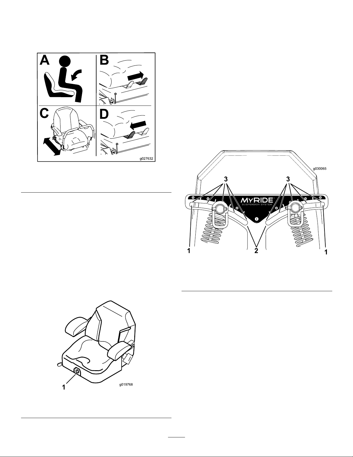
PositioningtheSeat
AdjustingtheRear-Shock
Theseatcanmoveforwardandbackward(Figure11).
Positiontheseatwhereyouhavethebestcontrolof
themachineandaremostcomfortable.
Figure11
SeatformachineswithMyRideshown.
Assemblies
MachineswithMyRide™
SuspensionSystemOnly
TheMyRide™suspensionsystemadjuststoprovide
asmoothandcomfortableride.Youcanadjustthe
rear2-shockassembliestoquicklyandeasilychange
thesuspensionsystem.Positionthesuspension
systemwhereyouaremostcomfortable.
Theslotsfortherear-shockassemblieshave
detentpositionsforreference.Youcanpositionthe
rear-shockassembliesanywhereintheslot,notjustin
thedetentpositions.Thefollowinggraphicshowsthe
positionforasoftorrmrideandthedifferentdetent
positions(Figure13).
g027632
ChangingtheSeat
Suspension
MachineswithoutMyRide™
SuspensionSystemOnly
Theseatisadjustabletoprovideasmoothand
comfortableride.Positiontheseatwhereyouare
mostcomfortable.
Toadjustit,turntheknobinfronteitherdirectionto
providethebestcomfort(Figure12).
g030065
Figure13
1.Firmestposition3.Detentsintheslots
2.Softestposition
Note:Ensurethattheleftandrightrear-shock
assembliesarealwaysadjustedtothesamepositions.
Adjusttherear-shockassemblies(Figure14).
1.Seat-suspensionknob
g019768
Figure12
19

Figure14
DuringOperation
DuringOperationSafety
GeneralSafety
g030024
g030019
•Theowner/operatorcanpreventandisresponsible
foraccidentsthatmaycausepersonalinjuryor
propertydamage.
•Useyourfullattentionwhileoperatingthe
machine.Donotengageinanyactivitythat
causesdistractions;otherwise,injuryorproperty
damagemayoccur.
•Donotoperatethemachinewhileill,tired,or
undertheinuenceofalcoholordrugs.
•Contactingthebladecanresultinseriouspersonal
injury.Shutofftheengine,removethekey,and
waitforallmovingpartstostopbeforeleavingthe
operatingposition.Whenyouturnthekeytothe
OFFposition,theengineshouldshutoffandthe
bladeshouldstop.Ifnot,stopusingyourmachine
immediatelyandcontactanAuthorizedService
Dealer.
•Operatethemachineonlyingoodvisibilityand
appropriateweatherconditions.Donotoperate
themachinewhenthereistheriskoflightning.
•Keepyourhandsandfeetawayfromthecutting
units.Keepclearofthedischargeopening.
•Donotmowwiththedischargedeector
raised,removed,oralteredunlessthereisa
grass-collectionsystemormulchkitinplaceand
workingproperly.
•Donotmowinreverseunlessitisabsolutely
necessary.Alwayslookdownandbehindyou
beforemovingthemachineinreverse.
•Useextremecarewhenapproachingblind
corners,shrubs,trees,orotherobjectsthatmay
blockyourview.
•Stopthebladeswheneveryouarenotmowing.
•Ifthemachinestrikesanobjectorstartstovibrate,
immediatelyshutofftheengine,removethekey
(ifequipped),andwaitforallmovingpartstostop
beforeexaminingthemachinefordamage.Make
allnecessaryrepairsbeforeresumingoperation.
•Slowdownandusecautionwhenmakingturns
andcrossingroadsandsidewalkswiththe
machine.Alwaysyieldtheright-of-way.
•Beforeyouleavetheoperatingposition,dothe
following:
–Parkthemachineonalevelsurface.
–Disengagethepowertakeoffandlowerthe
attachments.
–Engagetheparkingbrake.
20

–Shutofftheengineandremovethekey .
–Waitforallmovingpartstostop.
•Operatetheengineonlyinwell-ventilatedareas.
Exhaustgasescontaincarbonmonoxide,which
islethalifinhaled.
•Neverleavearunningmachineunattended.
•Attachtowedequipmenttothemachineonlyat
thehitchpoint.
•Donotoperatethemachineunlessallguardsand
safetydevices,suchasthedeectorsandthe
entiregrasscatcher,areinplaceandfunctioning
properly.Replacewornordeterioratedpartswhen
necessary.
•Useonlyaccessoriesandattachmentsapproved
byToro.
•Thismachineproducessoundlevelsinexcess
of85dBAattheoperator’searandcancause
hearinglossthroughextendedperiodsof
exposure.
•Beforebackinguporturningthemachine,look
downandallaroundforsmallchildren.
•Donotcarrychildrenonthemachine,evenwhen
thebladesarenotmoving.Childrencouldfall
offandbeseriouslyinjuredorpreventyoufrom
safelyoperatingthemachine.Childrenwhohave
beengivenridesinthepastcouldappearinthe
operatingareawithoutwarningandberunoveror
backedoverbythemachine.
RolloverProtectionSystem
(ROPS)Safety
•TheROPSisanintegralsafetydevice.Donot
removeanyoftheROPScomponentsfromthe
machine.
•Ensurethattheseatbeltisattachedandthatyou
canreleaseitquicklyinanemergency.
•Keeptherollbarinthefullyraisedandlocked
positionandalwayswearyourseatbeltwhenever
therollbarisup.
•Checkcarefullyforoverheadobjectsbeforeyou
driveunderthem,anddonotcontactthem.
Figure15
1.Wearhearingprotection.
•Cleangrassanddebrisfromthecuttingunit,
drives,mufer,andenginetohelppreventres.
•Starttheenginewithyourfeetwellawayfromthe
blades.
•Beawareofthemowerdischargepathanddirect
thedischargeawayfromothers.Avoiddischarging
materialagainstawallorobstructionbecausethe
materialmayricochetbacktowardyou.
•Stoptheblades,slowdownthemachine,anduse
cautionwhencrossingsurfacesotherthangrass
orwhentransportingthemachinetoandfromthe
operatingarea.
•Donotchangetheenginegovernorspeedor
overspeedtheengine.
•Childrenareoftenattractedtothemachineand
themowingactivity.Neverassumethatchildren
willremainwhereyoulastsawthem.
•Keepchildrenoutoftheoperatingareaandunder
thewatchfulcareofaresponsibleadultotherthan
theoperator.
•Bealertandshutoffthemachineifchildrenenter
theoperatingarea.
•ReplacedamagedROPScomponents.Donot
repairoralterthem.
g229846
•Thereisnorolloverprotectionwhentherollbar
isdown.
•Wheelsdroppingoveredges,oversteepbanks,or
intowatercancausearollover,whichmayresult
inseriousinjuryordeath.
•Donotweartheseatbeltwhentherollbarisdown.
•Lowertherollbaronlywhenabsolutelynecessary;
raiseitassoonasclearancepermits.
•Intheeventofarollover,takethemachinetoan
AuthorizedServiceDealertoinspecttheROPS.
•UseonlyToroapprovedaccessoriesand
attachmentsfortheROPS.
SlopeSafety
•Slopesareamajorfactorrelatedtolossofcontrol
androlloveraccidents,whichcanresultinsevere
injuryordeath.Theoperatorisresponsiblefor
safeslopeoperation.Operatingthemachineon
anysloperequiresextracaution.Beforeusingthe
machineonaslope,dothefollowing:
–Reviewandunderstandtheslopeinstructions
inthemanualandonthemachine.
–Useanangleindicatortodeterminethe
approximateslopeangleofthearea.
–Neveroperateonslopesgreaterthan15°.
21
–Evaluatethesiteconditionsofthedayto
determineiftheslopeissafeformachine
operation.Usecommonsenseandgood
judgmentwhenperformingthisevaluation.
Changesintheterrain,suchasmoisture,can
quicklyaffecttheoperationofthemachineon
aslope.
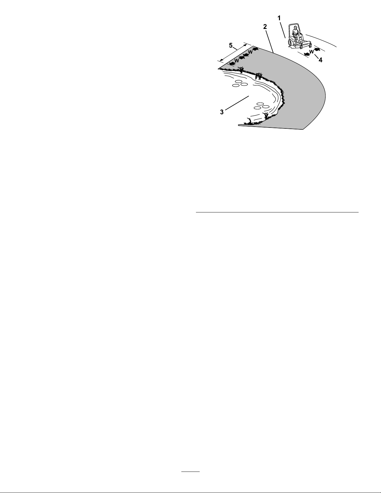
•Identifyhazardsatthebaseoftheslope.Do
notoperatethemachineneardrop-offs,ditches,
embankments,water,orotherhazards.The
machinecouldsuddenlyrolloverifawheelgoes
overtheedgeortheedgecollapses.Keepasafe
distance(twicethewidthofthemachine)between
themachineandanyhazard.Useawalk-behind
machineorahandtrimmertomowthegrassin
theseareas.
•Avoidstarting,stopping,orturningthemachineon
slopes.Avoidmakingsuddenchangesinspeedor
direction;turnslowlyandgradually.
•Donotoperateamachineunderanyconditions
wheretraction,steering,orstabilityisinquestion.
Beawarethatoperatingthemachineonwet
grass,acrossslopes,ordownhillmaycausethe
machinetolosetraction.Lossoftractiontothe
drivewheelsmayresultinslidingandalossof
brakingandsteering.Themachinecanslideeven
ifthedrivewheelsarestopped.
1.SafeZone—usethe
machinehereonslopes
lessthan15°oratareas.
2.DangerZone—usea
walk-behindmowerand/or
ahandtrimmeronslopes
greaterthan15°andnear
drop-offsorwater.
3.Water
g221745
Figure16
4.W=Widthofthemachine
5.Keepasafedistance
(twicethewidthofthe
machine)betweenthe
machineandanyhazard.
•Removeormarkobstaclessuchasditches,holes,
ruts,bumps,rocks,orotherhiddenhazards.T all
grasscanhideobstacles.Uneventerraincould
overturnthemachine.
•Useextracarewhileoperatingwithaccessoriesor
attachments,suchasgrass-collectionsystems.
Thesecanchangethestabilityofthemachine
andcausealossofcontrol.Followdirectionsfor
counterweights.
•Ifpossible,keepthedeckloweredtotheground
whileoperatingonslopes.Raisingthedeckwhile
operatingonslopescancausethemachineto
becomeunstable.
22

EnteringtheOperator’s
Position
Usethemowerdeckasasteptogetintothe
operator’sposition(Figure17).
Figure17
1.Stephere.
DisengagingtheParkingBrake
g283914
Figure19
g029797
OperatingtheParking
Brake
Alwaysengagetheparkingbrakewhenyoustopthe
machineorleaveitunattended.
EngagingtheParkingBrake
Parkthemachineonalevelsurface.
Figure18
g283915
23
OperatingtheMower
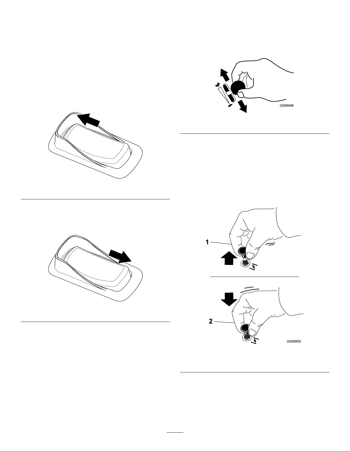
OperatingtheThrottle
Blade-ControlSwitch(PTO)
Theblade-controlswitch(PTO)startsandstopsthe
mowerbladesandanypoweredattachments.
EngagingtheBlade-Control
Switch(PTO)
Note:Engagingtheblade-controlswitch(PTO)with
thethrottlepositionathalforlesscausesexcessive
weartothedrivebelts.
Figure20
YoucanmovethethrottlecontrolbetweenFASTand
SLOWpositions(Figure22).
AlwaysusetheFASTpositionwhenengagingthePTO.
g008946
Figure22
OperatingtheChoke
Usethechoketostartacoldengine.
g332523
1.Pullupthechokeknobtoengagethechoke
beforeusingthekeyswitch(Figure23).
2.Pushdownthechokeknobtodisengagethe
chokeaftertheenginehasstarted(Figure23).
DisengagingtheBlade-Control
Switch(PTO)
g332522
Figure21
g008959
Figure23
1.ONposition2.OFFposition
24
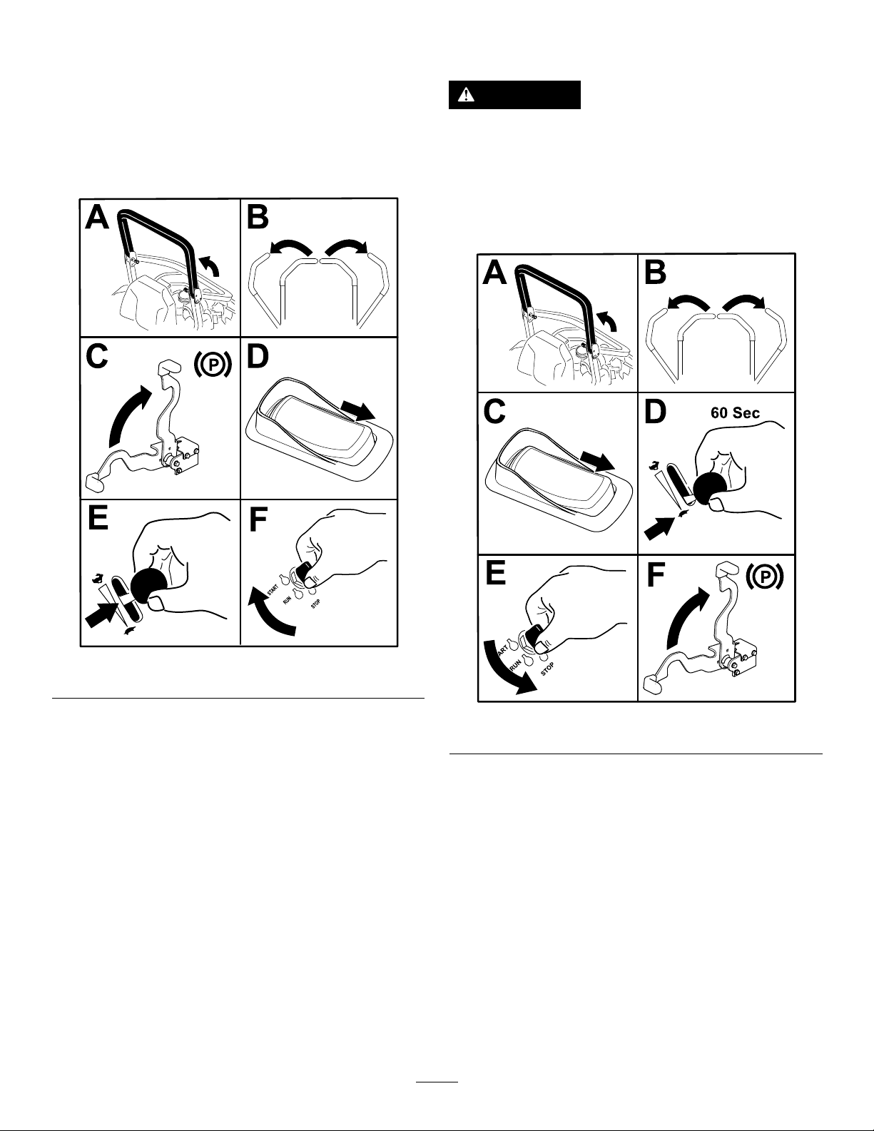
StartingtheEngine
Note:Awarmorhotenginemaynotrequirechoking.
Important:Donotengagethestarterformore
than5secondsatatime.Engagingthestarter
motorformorethan5secondscandamagethe
startermotor.Iftheenginefailstostart,wait10
secondsbeforeoperatingtheenginestarteragain.
ShuttingOfftheEngine
CAUTION
Childrenorbystandersmaybeinjuredifthey
moveorattempttooperatethemachinewhile
itisunattended.
Alwaysremovethekeyandengagethe
parkingbrakewhenleavingthemachine
unattended.
Figure24
g332530
g332529
Figure25
25

UsingtheMotion-Control
DrivingtheMachine
Levers
Thedrivewheelsturnindependently,poweredby
hydraulicmotorsoneachaxle.Youcanturn1side
inreversewhileyouturntheotherforward,causing
themachinetospinratherthanturn.Thisgreatly
improvesthemachinemaneuverabilitybutmay
requiresometimeforyoutoadapttohowitmoves.
Thethrottlecontrolregulatestheenginespeedas
measuredinrpm(revolutionsperminute).Place
thethrottlecontrolintheFASTpositionforbest
performance.Alwaysoperateinthefullthrottle
positionwhenmowing.
WARNING
Themachinecanspinveryrapidly.You
maylosecontrolofthemachineandcause
personalinjuryordamagetothemachine.
•Usecautionwhenmakingturns.
•Slowthemachinedownbeforemaking
sharpturns.
DrivingForward
Figure26
1.Motion-control
levers—NEUTRAL-LOCK
position
2.Center,unlockedposition5.Frontofthemachine
3.Forward
4.Reverse
Note:Theengineshutsoffwhenyoumovethe
g004532
traction-controlwiththeparkingbrakeengaged.
Tostopthemachine,pullthemotion-controllevers
totheNEUTRALposition.
1.Disengagetheparkingbrake.
2.Movethemotion-controlleverstothecenter,
unlockedposition.
3.T ogoforward,slowlypushthemotion-control
leversforward(Figure27).
26

Figure27
DrivinginReverse
1.Movethemotion-controlleverstothecenter,
unlockedposition.
2.T ogoinreverse,slowlypullthemotion-control
leversrearward(Figure28).
UsingtheSideDischarge
Themowerhasahingedgrassdeectorthat
dispersesclippingstothesideanddowntowardthe
turf.
DANGER
Withoutagrassdeector,dischargecover,or
acompletegrass-catcherassemblymounted
inplace,youandothersareexposedtoblade
contactandthrowndebris.Contactwith
rotatingmowerblade(s)andthrowndebris
willcauseinjuryordeath.
•Neverremovethegrassdeectorfromthe
mowerdeckbecausethegrassdeector
routesmaterialdowntowardtheturf.Ifthe
grassdeectoriseverdamaged,replaceit
immediately.
•Neverputyourhandsorfeetunderthe
g008952
mowerdeck.
•Nevertrytoclearthedischargearea
ormowerbladesunlessyoumovethe
blade-controlswitch(PTO)totheOFF
position,rotatethekeyswitchtotheOFF
position,andremovethekeyfromthekey
switch.
•Makesurethatthegrassdeectorisinthe
downposition.
Figure28
g008953
27

AdjustingtheHeightofCut
AdjustingtheHeight-of-CutPin
ForMachineswithaDeck-Lift
Pedal
UsingtheTransportLock
1.Pushthedeck-liftpedalfullyforwardtolockthe
mowerdeckintheTRANSPORTposition(Figure
29).
2.Pushthedeck-liftpedalforwardandpushthe
transportlockforwardtotheUNLOCKposition,
thenslowlylowerthemowerdeck.(Figure29).
Youcanadjusttheheightofcutfrom38to140mm
(1-1/2to5-1/2inches)in6mm(1/4inch)increments
byrelocatingtheclevispinintodifferentholelocations.
1.Pushthedeck-liftpedalfullyforwardtolockthe
mowerdeckintheTRANSPORTposition(alsothe
140mm/5-1/2inchescuttingheightposition)as
showninFigure30.
2.T oadjust,removethepinfromtheheight-of-cut
bracket(Figure30).
3.Selectaholeintheheight-of-cutbracket
correspondingtotheheightofcutdesired,and
insertthepin(Figure30).
4.Pushthedeck-liftpedalforward,pushthe
transportlockforward,andslowlylowerthe
mowerdeck.
1.LOCKposition—the
mowerdecklocksinto
thetransportposition.
2.UNLOCKposition—the
mowerdeckdoesnotlock
intothetransportposition.
Figure29
3.Pushonthedeck-liftpedal
usingyourfoottoraisethe
mowerdeck.
g332768
Figure30
1.Deck-liftpedal3.Height-of-cutpin
2.Height-of-cutbracket
4.Transport-locklever
g332767
28

AdjustingtheHeightofCut
AdjustingtheAnti-Scalp
ForMachineswithanElectric
DeckLift
1.Pushuponthedeck-liftswitch(Figure31).
Figure31
1.Pushuptoraisethedeck.2.Pushdowntolowerthe
deck.
2.Selectaholeintheheight-of-cutbracket
correspondingtotheheightofcutdesired,and
insertthepin(Figure32).
Rollers
Wheneveryouchangetheheight-of-cut,adjustthe
heightoftheanti-scalprollers.
1.Parkthemachineonalevelsurface,disengage
theblade-controlswitch,andengagetheparking
brake.
2.Shutofftheengine,removethekey ,andwait
forallmovingpartstostopbeforeleavingthe
operatingposition.
3.Adjusttheanti-scalprollersasshowninFigure
33,Figure34,andFigure35.
g332765
g029955
Figure33
1.Anti-scalproller4.Flangenut
2.Spacer
3.Bushing
5.Bolt
3.Pushdownonthedeck-liftswitchuntilthe
height-of-cutlinkageslightlycontactsthe
height-of-cutpin(Figure32).
Note:T oomuchcontactbetweenthe
height-of-cutlinkageandheight-of-cutpincan
negativelyaffectthemowerdeckheightofcut
andleveling.
Figure32
1.Height-of-cutpin3.Height-of-cutbracket
2.Height-of-cutlinkage
g029956
Figure34
1.Anti-scalproller3.Flangenut
2.Bushing4.Bolt
g361935
29

Figure35
OperatingTips
UsingtheFastThrottleSetting
Forbestmowingandmaximumaircirculation,operate
theengineattheFASTposition.Airisrequiredto
thoroughlycutgrassclippings,sodonotsetthe
height-of-cutsolowastototallysurroundthemower
deckinuncutgrass.Alwaystrytohave1sideofthe
mowerdeckfreefromuncutgrass,whichallowsair
tobedrawnintothemowerdeck.
g029957
CuttingaLawnfortheFirstTime
1.Anti-scalproller4.Flangenut
2.Spacer
3.Bushing
5.Bolt
Cutgrassslightlylongerthannormaltoensurethat
thecuttingheightofthemowerdeckdoesnotscalp
anyunevenground.However,thecuttingheight
usedinthepastisgenerallythebestonetouse.
Whencuttinggrasslongerthan15cm(6inches)tall,
youmaywanttocutthelawntwicetoensurean
acceptablequalityofcut.
CuttingaThirdoftheGrassBlade
Itisbesttocutonlyaboutathirdofthegrassblade.
Cuttingmorethanthatisnotrecommendedunless
grassissparse,oritislatefallwhengrassgrows
moreslowly.
AlternatingtheMowingDirection
Alternatethemowingdirectiontokeepthegrass
standingstraight.Thisalsohelpsdisperseclippings,
whichenhancesdecompositionandfertilization.
MowingatCorrectIntervals
Grassgrowsatdifferentratesatdifferenttimesof
theyear.Tomaintainthesamecuttingheight,mow
moreofteninearlyspring.Asthegrassgrowthrate
slowsinmidsummer,mowlessfrequently .Ifyou
cannotmowforanextendedperiod,rstmowata
highcuttingheight,thenmowagain2dayslaterata
lowerheightsetting.
UsingaSlowerCuttingSpeed
Toimprovecutquality ,useaslowergroundspeed
incertainconditions.
AvoidingCuttingTooLow
Whenmowinguneventurf,raisethecuttingheight
toavoidscalpingtheturf.
StoppingtheMachine
Ifyoumuststoptheforwardmotionofthemachine
whilemowing,aclumpofgrassclippingsmay
30

dropontoyourlawn.Toavoidthis,moveontoa
previouslycutareawiththebladesengagedoryou
candisengagethemowerdeckwhilemovingforward.
KeepingtheUndersideofthe
MowerDeckClean
Cleanclippingsanddirtfromtheundersideofthe
mowerdeckaftereachuse.Ifgrassanddirtbuildup
insidethemowerdeck,cuttingqualitywilleventually
becomeunsatisfactory.
MaintainingtheBlade(s)
UsingtheFuel-Shutoff
Valve
Closethefuel-shutoffvalvefortransport,maintenance,
andstorage(Figure36).
Ensurethatthefuel-shutoffvalveisopenwhen
startingtheengine.
Maintainasharpbladethroughoutthecuttingseason
becauseasharpbladecutscleanlywithouttearingor
shreddingthegrassblades.Tearingandshredding
turnsgrassbrownattheedges,whichslowsgrowth
andincreasesthechanceofdisease.Checkthe
mowerbladesaftereachuseforsharpness,and
foranywearordamage.Filedownanynicksand
sharpenthebladesasnecessary .Ifabladeis
damagedorworn,replaceitimmediatelywitha
genuineT ororeplacementblade.
AfterOperation
AfterOperationSafety
GeneralSafety
•Shutofftheengine,removethekey,andwait
forallmovingpartstostopbeforeleavingthe
operator’sposition.Allowthemachinetocool
beforeservicing,adjusting,fueling,cleaning,or
storingit.
g036849
g008948
Figure36
1.ONposition2.OFFposition
UsingtheDrive-Wheel
•Cleangrassanddebrisfromthecuttingunit,
mufer,drives,grasscatcher,andengine
compartmenttohelppreventres.Cleanupoilor
fuelspills.
•Shutoffthefuelandremovethekeybeforestoring
ortransportingthemachine.
ReleaseValves
WARNING
Handsmaybecomeentangledintherotating
drivecomponentsbelowtheenginedeck,
whichcouldresultinseriousinjury.
Shutofftheengine,removethekey,andallow
allmovingpartstostopbeforeaccessingthe
drive-wheelreleasevalves.
31

WARNING
Theengineandhydraulic-driveunitscan
becomeveryhot.Touchingahotengineor
hydraulic-driveunitscancausesevereburns.
Allowtheengineandhydraulic-driveunits
tocoolcompletelybeforeaccessingthe
drive-wheelreleasevalves.
ForMachineswithZT4400Hydros
Thedrive-wheelreleasevalvesarelocatedontheleft
andrightsidesunderneaththeenginedeck.
1.Parkthemachineonalevelsurface,disengage
theblade-controlswitch,andengagetheparking
brake.
2.Shutofftheengine,removethekey ,andwait
forallmovingpartstostopbeforeleavingthe
operatingposition.
3.T opushthemachine,movebothbypasslevers
forwardandlockthemintoplace(Figure37).
ForMachineswithZT5400Hydros
Thedrive-wheelreleasevalvesarelocatedontheleft
andrightsidesunderneaththeenginedeck.
1.Parkthemachineonalevelsurface,disengage
theblade-controlswitch,andengagetheparking
brake.
2.Shutofftheengine,removethekey ,andwait
forallmovingpartstostopbeforeleavingthe
operatingposition.
3.Usingaat-headscrewdriver,rotatebothcams
totheBYP ASSposition(Figure38).
4.Disengagetheparkingbrakebeforepushing
themachine.
5.T orunthemachine,rotatebothcamstotheRUN
position(Figure38).
4.Disengagetheparkingbrakebeforepushing
themachine.
5.T orunthemachine,movethebypasslevers
rearwardandlockthemintoplace(Figure37).
Figure37
g332789
Figure38
1.Rotatethecamtothe
BYPASSposition.
g332790
2.RotatethecamtotheRUN
position.
1.Bypasslever
32

TransportingtheMachine
Useaheavy-dutytrailerortrucktotransportthe
machine.Useafull-widthramp.Ensurethatthetrailer
ortruckhasallthenecessarybrakes,lighting,and
markingasrequiredbylaw.Pleasecarefullyreadall
thesafetyinstructions.Knowingthisinformationcould
helpyouorbystandersavoidinjury.Refertoyour
localordinancesfortrailerandtie-downrequirements.
WARNING
Drivingonthestreetorroadwaywithout
turnsignals,lights,reectivemarkings,ora
slow-moving-vehicleemblemisdangerous
andcanleadtoaccidents,causingpersonal
injury.
Donotdrivethemachineonapublicstreet
orroadway.
SelectingaTrailer
WARNING
Loadingamachineontoatrailerortruck
increasesthepossibilityoftip-overandcould
causeseriousinjuryordeath(Figure39).
•Useonlyafull-widthramp;donotuse
individualrampsforeachsideofthe
machine.
•Donotexceeda15-degreeanglebetween
therampandthegroundorbetweenthe
rampandthetrailerortruck.
•Ensurethatthelengthoftherampisat
least4timesaslongastheheightofthe
trailerortruckbedtotheground.This
ensuresthattherampangledoesnot
exceed15degreesonatground.
Figure39
1.Full-widthrampinstowed
position
2.Sideviewoffull-width
rampinloadingposition
3.Notgreaterthan
15degrees
4.Rampisatleast4times
aslongastheheightof
thetrailerortruckbedto
theground
5.H=heightofthetraileror
truckbedtotheground
6.Trailer
LoadingtheMachine
WARNING
Loadingamachineontoatrailerortruck
increasesthepossibilityoftip-overandcould
causeseriousinjuryordeath.
•Useextremecautionwhenoperatinga
machineonaramp.
g027996
•Backthemachineuptherampanddriveit
forwarddowntheramp.
•Avoidsuddenaccelerationordeceleration
whiledrivingthemachineonarampas
thiscouldcausealossofcontrolora
tip-oversituation.
33

1.Ifusingatrailer,connectittothetowingvehicle
andconnectthesafetychains.
2.Ifapplicable,connectthetrailerbrakesand
lights.
3.Lowertheramp,ensuringthattheangle
betweentherampandthegrounddoesnot
exceed15degrees(Figure39).
4.Backthemachineuptheramp(Figure40).
Figure40
UnloadingtheMachine
1.Lowertheramp,ensuringthattheangle
betweentherampandthegrounddoesnot
exceed15degrees(Figure39).
2.Drivethemachineforwarddowntheramp
(Figure40).
g028043
1.Backthemachineupthe
ramp.
2.Drivethemachineforward
downtheramp.
5.Shutofftheengine,removethekey,andengage
theparkingbrake.
6.Tiedownthemachinenearthefrontcaster
wheelsandtherearframewithstraps,chains,
cable,orropes(Figure41).Refertolocal
regulationsfortie-downrequirements.
1.Tie-downpoints
g332791
Figure41
34

Maintenance
MaintenanceSafety
•Ifyouleavethekeyintheswitch,someonecould
accidentlystarttheengineandseriouslyinjureyou
orotherbystanders.Removethekeyfromthe
switchbeforeyouperformanymaintenance.
•Beforeyouleavetheoperator’sposition,dothe
following:
–Parkthemachineonalevelsurface.
–Disengagethedrives.
–Engagetheparkingbrake.
–Shutofftheengineandremovethekey .
–Allowmachinecomponentstocoolbefore
performingmaintenance.
•Donotallowuntrainedpersonneltoservicethe
machine.
•Keepyourhandsandfeetawayfrommoving
partsorhotsurfaces.Ifpossible,donotmake
adjustmentswiththeenginerunning.
•Carefullyreleasepressurefromcomponentswith
storedenergy.
•Checktheparkingbrakeoperationfrequently.
Adjustandserviceitasrequired.
•Nevertamperwithsafetydevices.Checktheir
properoperationregularly.
•Cleangrassanddebrisfromthecuttingunit,
mufer,drives,grasscatcher,andengine
compartmenttopreventres.
•Cleanupoilorfuelspillsandremovefuel-soaked
debris.
•Donotrelyonhydraulicormechanicaljacksto
supportthemachine;supportthemachinewith
jackstandswheneveryouraisethemachine.
•Keepallpartsingoodworkingcondition
andallhardwaretightened,especiallythe
blade-attachmenthardware.Replaceallwornor
damageddecals.
•Disconnectthecablefromthenegativeterminalof
thebatterybeforerepairingthemachine.
•Toensureoptimumperformance,useonly
genuineT ororeplacementpartsandaccessories.
Replacementpartsandaccessoriesmadeby
othermanufacturerscouldbedangerous,and
suchusecouldvoidtheproductwarranty.
RecommendedMaintenanceSchedule(s)
MaintenanceService
Interval
Aftertherst100hours
Beforeeachuseordaily
Aftereachuse
Every50hours
Every100hours
MaintenanceProcedure
•Changethehydraulic-systemltersanduid.
•Checkthesafety-interlocksystem.
•ForKawasakiengines—checktheengine-oillevel.
•ForKohlerEngines—checktheengine-oillevel.
•Cleantheenginescreen,engine-oilcooler,andtheareaaroundtheengine.
•Cleanaroundtheengine-exhaustsystem.
•Checktheseatbelt.
•Checkthehydraulic-uidlevelintheexpansiontank.
•Inspecttheblades.
•Cleanthesuspensionsystem.
•Cleanthemowerdeck.
•Checkthesparkarrester(ifequipped).
•Checkthetirepressure.Formachineswithpneumatictiresonly.
•Inspectthebeltsforcracksandwear.
•Lubricatethemowerdeck-liftpivots.
•ForKawasakiengines—changetheengineoil(moreoftenindirtyordusty
•ForKawasakiengines—replaceorcleanandgapthesparkplug.
•ForKohlerEngines—changetheengineoil(moreoftenindirtyordustyconditions).
conditions).
Every150hours
•ForKohlerengines—inspecttheprimarylter(moreoftenindirtyordusty
conditions).
35

MaintenanceService
Every200hours
Every250hours
Every300hours
Interval
MaintenanceProcedure
•ForKawasakiengines—changetheengine-oillter(moreoftenindirtyordusty
conditions).
•ForKohlerEngines—changetheengine-oillter(moreoftenindirtyordusty
conditions).
•ForKohlerEngines—checkthesparkplug(s).
•ForKawasakiengines—replacetheprimaryairlter(moreoftenindirtyordusty
conditions).
•ForKawasakiengines—checkthesafetyairlter(moreoftenindirtyordusty
conditions).
•ForKawasakiengines—Checkandadjustthevalveclearance.SeeanAuthorized
ServiceDealer.
•ForKohlerengines—replacetheprimaryairlter(moreoftenindirtyordusty
conditions).
•ForKohlerengines—checktheinnerairlter(moreoftenindirtyordustyconditions).
Every400hours
Every400hoursoryearly,
whichevercomesrst
Every500hours
Every600hours
Monthly
Yearly
Yearlyorbeforestorage
•Greasethecasterpivots(moreoftenindirtyordustyconditions).
•Aftertheinitialchange—changethehydraulic-systemltersanduidwhenusing
Toro®HYPR-OIL™500uid(changeitmoreoftenunderdirtyordustyconditions).
•ForKawasakiengines—replacethesafetyairlter(moreoftenindirtyordusty
conditions).
•ForKohlerEngines—replacethesparkplug(s).
•Replacethefuellter(moreoftenindusty,dirtyconditions).
•ForKohlerengines—replacetheinnerairlter.
•Checkthebatterycharge.
•Repackthecaster-wheelbearings(moreoftenindirtyordustyconditions).
•Greasingthecaster-wheelhubs.
•Paintchippedsurfaces.
•CompletealltheproceduresintheStoragechapter.
Important:Refertoyourengineowner'smanualforadditionalmaintenanceprocedures.
CAUTION
Ifyouleavethekeyintheswitch,someonecouldaccidentlystarttheengineandseriously
injureyouorotherbystanders.
Shutofftheengineandremovethekeyfromtheswitchbeforeyouperformanymaintenance.
36
Lubrication
GreasingtheMachine
Greasethemachinemoreoftenindirtyordusty
conditions.
GreasingtheCasterPivots
ServiceInterval:Every400hours/Yearly(whichever
comesrst)(moreoftenindirtyor
dustyconditions).
Yearly—Repackthecaster-wheelbearings
(moreoftenindirtyordustyconditions).
GreaseType:No.2lithiumormolybdenumgrease
1.Parkthemachineonalevelsurface,disengage
theblade-controlswitch,andengagetheparking
brake.
2.Shutofftheengine,removethekey ,andwait
forallmovingpartstostopbeforeleavingthe
operatingposition.
3.Cleanthegreasettingswitharag.
Note:Scrapeanypaintoffthefrontofthe
tting(s).
4.Connectagreaseguntothetting.
5.Pumpgreaseintothettingsuntilgreasebegins
tooozeoutofthebearings.
6.Wipeupanyexcessgrease.
LubricatingtheMower
Deck-LiftPivots
ServiceInterval:Every100hours
Uselightoilorspraylubricanttolubricatethedeck-lift
pivots.
1.Parkthemachineonalevelsurface,disengage
theblade-controlswitch,andengagetheparking
brake.
2.Shutofftheengine,removethekey ,andwait
forallmovingpartstostopbeforeleavingthe
operatingposition.
3.Removethedustcapandadjustthecaster
pivotsandkeepthedustcapoffuntilgreasingis
done;refertoGreasingtheMachine(page37).
4.Removethehexplug.
5.Threadagreasettingintothehole.
6.Pumpgreaseintothettinguntilitoozesout
aroundthetopbearing.
7.Removethegreasettingfromthehole.Install
thehexplugandcap.
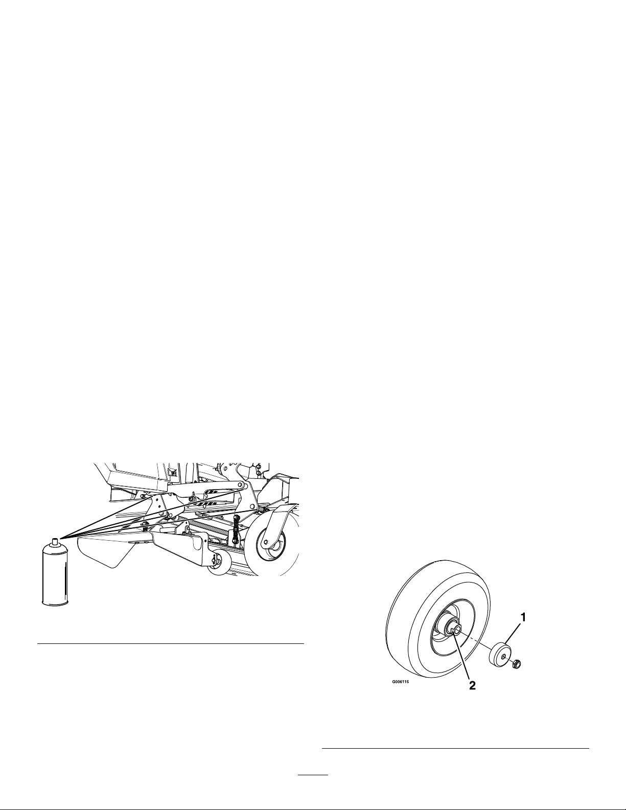
GreasingtheCaster-Wheel
Hubs
ServiceInterval:Yearly
1.Parkthemachineonalevelsurface,disengage
theblade-controlswitch,andengagetheparking
brake.
Figure42
2.Shutofftheengine,removethekey ,andwait
forallmovingpartstostopbeforeleavingthe
operatingposition.
3.Raisethemowerforaccess.
4.Removethecasterwheelfromthecasterforks.
5.Removethesealguardsfromthewheelhub.
g336930
g006115
Figure43
1.Sealguard2.Spacernutwithwrench
ats
37

6.Removeaspacernutfromtheaxleassemblyin
thecasterwheel.
Note:Thread-lockingcompoundhasbeen
appliedtolockthespacernutstotheaxle.
7.Removetheaxle(withtheotherspacernutstill
assembledtoit)fromthewheelassembly.
8.Pryoutsealsandinspectbearingsforwearor
damageandreplaceifnecessary.
9.Packthebearingswithageneral-purpose
grease.
10.Insert1bearingand1newsealintothewheel.
11.Iftheaxleassemblyismissingbothspacernuts,
applyathread-lockingcompoundto1spacer
nutandthreaditontotheaxlewiththewrench
atsfacingoutward.
Note:Donotthreadthespacernutallof
thewayontotheendoftheaxle.Leave
approximately3mm(1/8inch)fromtheouter
surfaceofthespacernuttotheendoftheaxle
insidethenut.
12.Inserttheassemblednutandaxleintothewheel
onthesidewiththenewsealandbearing.
13.Withtheopenendofthewheelfacingup,ll
theareainsidethewheelaroundtheaxlefullof
general-purposegrease.
14.Insertthesecondbearingandnewsealintothe
wheel.
15.Applyathread-lockingcompoundtothesecond
spacernut,andthreaditontotheaxlewiththe
wrenchatsfacingoutward.
16.T orquethenutto8to9N∙m(75to80in-lb),
loosenthenut,thentorqueitto2to3N∙m(20
to25in-lb).
Note:Makesurethattheaxledoesnotextend
beyondeithernut.
17.Installthesealguardsoverthewheelhub,and
insertthewheelintothecasterfork.
18.Installthecasterboltandtightenthenutfully.
Important:Topreventsealandbearingdamage,
checkthebearingadjustmentoften.Spinthe
castertire.Thetireshouldnotspinfreely(more
than1or2revolutions)orhaveanysideplay.If
thewheelspinsfreely,adjustthetorqueonthe
spacernutuntilthereisaslightamountofdrag.
Applyanotherlayerofthread-lockingcompound.
38

EngineMaintenance
surfaces.Allowenginecomponentstocoolbefore
performingmaintenance.
•Donotchangetheenginegovernorspeedor
EngineSafety
overspeedtheengine.
•Keepyourhands,feet,face,otherbodyparts,
andclothingawayfromthemuferandotherhot
IdentifyingtheEngine
Usethefollowinggraphictoidentifytheengineyouhaveandproceedtothesectionlistedbelowforservice
(Figure44).
Figure44
1.Kawasakiengine2.Kohlerengine
•ForKawasakienginemaintenance,refertoServicingaKawasaki
•ForKohlerenginemaintenance,refertoServicingaKohler
®
Engine(page40).
®
Engine(page45).
g230252
39
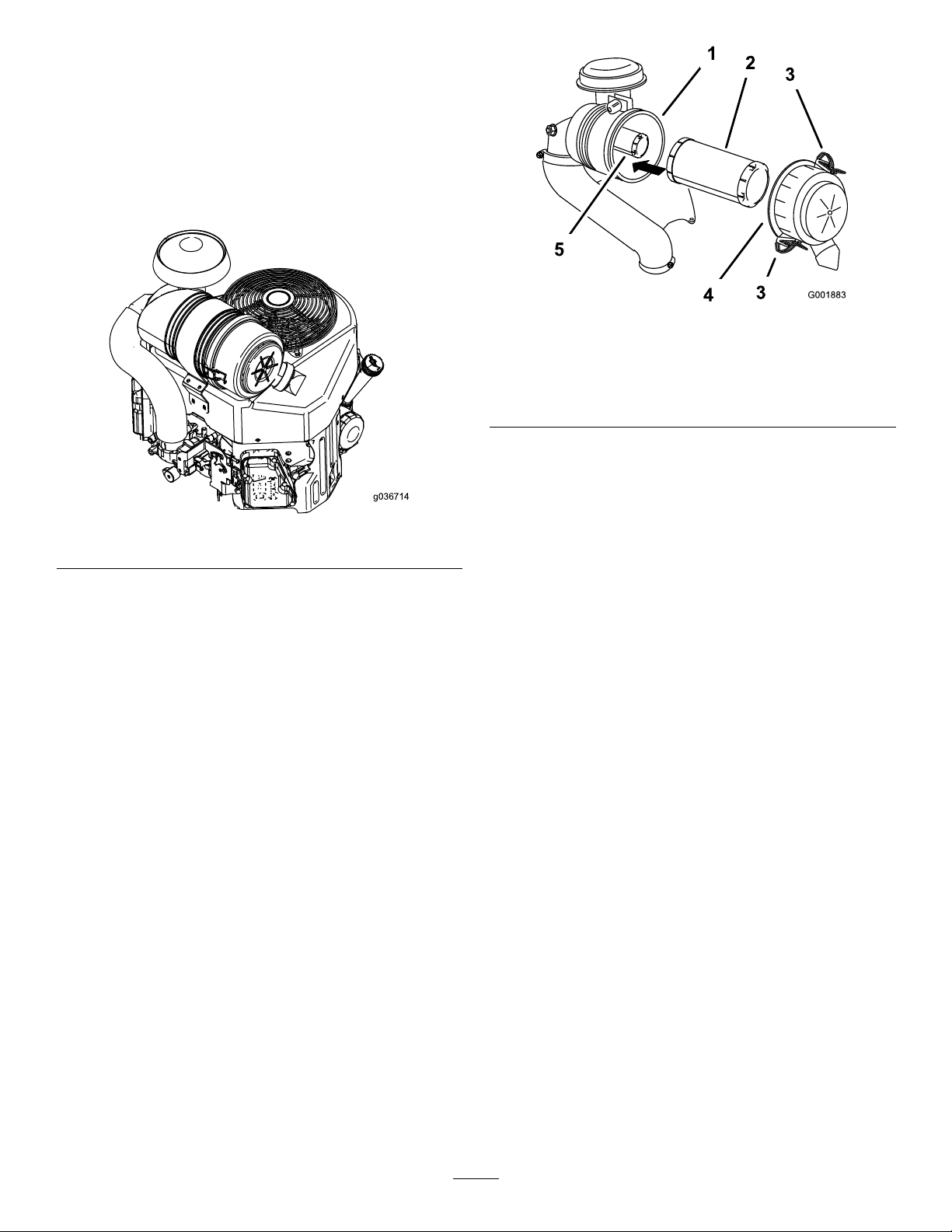
ServicingaKawasaki
®
Engine
ThissectionisonlyformachineswithKawasaki
engines.Ifyourenginelooksliketheoneshownin
Figure45,youhaveaKawasakiengine.
Important:Refertoyourengineowner’smanual
foradditionalmaintenanceprocedures.
Figure45
g001883
Figure46
1.Air-cleanerbody4.Air-cleanercover
2.Primarylter5.Safetylter
3.Latch
4.Cleantheinsideoftheair-cleanercoverwith
compressedair.
5.Gentlyslidetheprimarylteroutofthe
g036714
air-cleanerbody(Figure46).
Note:Avoidknockingthelterintothesideof
thebody.
ServicingtheAirCleaner
ServiceInterval:Every250hours—ForKawasaki
engines—replacetheprimaryair
lter(moreoftenindirtyordusty
conditions).
Every250hours—ForKawasaki
engines—checkthesafetyairlter(moreoften
indirtyordustyconditions).
Every500hours—ForKawasaki
engines—replacethesafetyairlter
(moreoftenindirtyordustyconditions).
Note:Servicetheaircleanermorefrequentlyif
operatingconditionsareextremelydustyorsandy .
RemovingtheFilters
1.Parkthemachineonalevelsurface,disengage
theblade-controlswitch(PTO),andengagethe
parkingbrake.
2.Shutofftheengine,removethekey ,andwait
forallmovingpartstostopbeforeleavingthe
operatingposition.
3.Releasethelatchesontheaircleanerandpull
theair-cleanercoverofftheair-cleanerbody
(Figure46).
6.Removethesafetylteronlytoreplaceit.
InspectingtheFilters
1.Inspectthesafetylter.Ifitisdirty ,replaceboth
thesafetyandprimarylters.
Important:Donotattempttocleanthe
safetylter.Ifthesafetylterisdirty ,then
theprimarylterisdamaged.
2.Inspecttheprimarylterfordamagebylooking
intothelterwhileshiningabrightlightonthe
outsideofthelter.Iftheprimarylterisdirty,
bent,ordamaged,replaceit.
Note:Holesinthelterappearasbrightspots.
Donotcleantheprimarylter.
InstallingtheFilters
Important:Topreventenginedamage,always
operatetheenginewithbothairltersandthe
coverinstalled.
1.Ifyouareinstallingnewlters,checkeachlter
forshippingdamage.
Note:Donotuseadamagedlter.
2.Ifyouarereplacingtheinnerlter,carefullyslide
itintothelterbody(Figure46).
40

3.Carefullyslidetheprimarylteroverthesafety
lter(Figure46).
Note:Ensurethattheprimarylterisfully
seatedbypushingontheouterrimwhile
installingit.
viscositytoaccommodateatmosphericconditions.
Using20W-50engineoilinhigherambient
temperaturescanreduceoilconsumption.
CheckingtheEngine-OilLevel
Important:Donotpressonthesoft,inside
areaofthelter.
4.Installtheair-cleanercoverandsecurethe
latches(Figure46).
ServicingtheEngineOil
ServiceInterval:Beforeeachuseordaily—For
Kawasakiengines—checkthe
engine-oillevel.
Every100hours—ForKawasaki
engines—changetheengineoil(more
oftenindirtyordustyconditions).
Every200hours—ForKawasaki
engines—changetheengine-oillter
(moreoftenindirtyordustyconditions).
Engine-OilSpecications
OilType:Detergentoil(APIserviceSF ,SG,SH,SJ,
orSL)
CrankcaseCapacity:
•KawasakiFX751andFX801engines—2.3L(78
oz)withalterchange;2.1L(71oz)without
alterchange
•KawasakiFX921andFX1000engines—1.9
L(64oz)withalterchange;1.7L(57oz)
withoutalterchange
Note:Checktheoilwhentheengineiscold.
Important:Ifyouoverllorunderlltheengine
crankcasewithoilandruntheengine,youmay
damagetheengine.
1.Parkthemachineonalevelsurface,disengage
theblade-controlswitch(PTO),andengagethe
parkingbrake.
2.Shutofftheengine,removethekey ,andwait
forallmovingpartstostopbeforeleavingthe
operatingposition.
Note:Ensurethattheengineiscoolsothatthe
oilhashadtimetodrainintothesump.
3.T okeepdirt,grassclippings,etc.,outofthe
engine,cleantheareaaroundtheoil-llcapand
dipstickbeforeremovingit(Figure48).
Viscosity:Seethetablebelow.
Figure47
Note:Although10W-40engineoilisrecommended
formostconditions,youmayneedtochangeoil
g037096
41

4.Shutofftheengine,removethekey ,andwait
forallmovingpartstostopbeforeleavingthe
operatingposition.
5.Draintheoilfromtheengine(Figure49).
g008804
g008804
Figure48
ChangingtheEngineOil
Note:Disposeoftheusedoilatarecyclingcenter.
1.Starttheengineandletitrunfor5minutes.
Note:Thiswarmstheoilsothatitdrainsbetter.
2.Parkthemachinesothatthedrainsideisslightly
lowerthantheoppositesidetoensurethatthe
oildrainscompletely.
3.Disengagetheblade-controlswitch(PTO)and
engagetheparkingbrake.
g311705
g027734
Figure49
42

6.Slowlypourapproximately80%ofthespecied
oilintothellertubeandslowlyaddthe
additionaloiltobringittotheFullmark(Figure
50).
g008804
Figure50
7.Starttheengineanddrivetoaatarea.
8.Checktheoillevelagain.
ChangingtheEngine-OilFilter
1.Draintheoilfromtheengine;refertoChanging
theEngineOil(page42).
2.Changetheengine-oillter(Figure51).
g194610
g027477
Figure51
Note:Ensurethattheoil-ltergaskettouches
theengine,andthenturntheoillteranextra
3/4turn.
3.Fillthecrankcasewiththepropertypeofnew
oil;refertoEngine-OilSpecications(page41).
43

ServicingtheSparkPlug(s)
CheckingtheSparkPlug(s)
ServiceInterval:Every100hours
Ensurethattheairgapbetweenthecenterandside
electrodesiscorrectbeforeinstallingthesparkplug.
Useasparkplugwrenchforremovingandinstalling
thesparkplugandagappingtoolorfeelergaugeto
checkandadjusttheairgap.Installanewsparkplug
ifnecessary.
TypeofSparkPlug:
•KawasakiFX751andFX801engines—NGK
BPR4ESorequivalent
•KawasakiFX921andFX1000engines—NGK
BPR5ESorequivalent
AirGap:0.75mm(0.030inch)
RemovingtheSparkPlug(s)
1.Parkthemachineonalevelsurface,disengage
theblade-controlswitch(PTO),andengagethe
parkingbrake.
2.Shutofftheengine,removethekey ,andwait
forallmovingpartstostopbeforeleavingthe
operatingposition.
Important:Donotcleanthesparkplug(s).
Alwaysreplacethesparkplug(s)whenithasa
blackcoating,wornelectrodes,anoilylm,or
cracks.
Ifyouseelightbrownorgrayontheinsulator,the
engineisoperatingproperly.Ablackcoatingonthe
insulatorusuallymeanstheaircleanerisdirty .
Setthegapto0.75mm(0.03inch).
®
®
g206628
Figure53
InstallingtheSparkPlug(s)
3.Cleantheareaaroundthebaseoftheplugto
keepdirtanddebrisoutoftheengine.
4.Locateandremovethesparkplug(s)asshown
inFigure52.
Figure52
g009922
g027661
Figure54
g027478
44

ServicingaKohler
ThissectionisonlyformachineswithKohlerengines.
IfyourenginelooksliketheoneshowninFigure55,
youhaveaKohlerengine.
®
Engine
Important:Refertoyourengineowner’smanual
foradditionalmaintenanceprocedures.
Figure55
g012996
Figure56
1.Air-inletcover3.Air-cleanerbody
2.Air-inletscreen4.Latch
6.Releasethelatchesontheaircleanerandpull
theair-cleanercoverofftheair-cleanerbody
g230254
(Figure57).
7.Cleantheinsideoftheair-cleanercoverwith
compressedair.
ServicingtheAirCleaner
ServiceInterval:Every150hours—ForKohler
engines—inspecttheprimary
lter(moreoftenindirtyordusty
conditions).
Every300hours/Y early(whichevercomes
rst)—ForKohlerengines—replacetheprimary
airlter(moreoftenindirtyordustyconditions).
Every300hours—ForKohlerengines—check
theinnerairlter(moreoftenindirtyordusty
conditions).
Every600hours—ForKohlerengines—replace
theinnerairlter.
RemovingtheFilters
1.Parkthemachineonalevelsurface,disengage
theblade-controlswitch(PTO),andengagethe
parkingbrake.
2.Shutofftheengine,removethekey ,andwait
forallmovingpartstostopbeforeleavingthe
operatingposition.
8.Gentlyslidetheprimarylteroutofthe
air-cleanerbody(Figure57).
Note:Avoidknockingthelterintothesideof
thebody.
9.Removetheinnerlteronlyifyouintendto
replaceit.
Important:Neverattempttocleantheinner
lter.Ifthesafetylterisdirty,thenthe
primarylterisdamaged.Replaceboth
lters.
3.Releasethelatchesontheaircleanerand
pulltheair-inletcoverofftheair-cleanerbody
(Figure56).
4.Cleantheair-inletscreenandcover.
5.Installtheair-inletcoverandsecureitwiththe
latches(Figure56).
45

1.Innerlter
2.Primarylter
3.Air-cleanercover
Figure57
4.Latch
5.Air-cleanerbody
Note:Ensurethattheprimarylterisfully
seatedbypushingontheouterrimwhile
installingit.
Important:Donotpressonthesoft,inside
areaofthelter.
4.Installtheair-cleanercoverandsecurethe
latches(Figure57).
ServicingtheEngineOil
ServiceInterval:Beforeeachuseordaily—For
KohlerEngines—checkthe
engine-oillevel.
Every100hours—ForKohlerEngines—change
theengineoil(moreoftenindirtyordusty
g012997
conditions).
Every200hours—ForKohlerEngines—change
theengine-oillter(moreoftenindirtyordusty
conditions).
Engine-OilSpecications
10.Inspecttheprimarylterfordamagebylooking
intothelter,whileshiningabrightlightonthe
outsideofthelter.
Note:Holesinthelterwillappearasbright
spots.Ifthelterisdamaged,discardit.
InspectingtheFilters
1.Inspecttheinnerlter.Ifitisdirty,replaceboth
theinnerandprimarylters.
Important:Donotattempttocleanthe
innerlter.Iftheinnerlterisdirty,thenthe
primarylterisdamaged.
2.Inspecttheprimarylterfordamagebylooking
intothelterwhileshiningabrightlightonthe
outsideofthelter.Iftheprimarylterisdirty,
bent,ordamaged,replaceit.
Note:Holesinthelterappearasbrightspots.
Donotcleantheprimarylter.
InstallingtheFilters
Important:Topreventenginedamage,always
operatetheenginewithbothairltersandthe
coverinstalled.
1.Ifyouareinstallingnewlters,checkeachlter
forshippingdamage.
Note:Donotuseadamagedlter.
2.Ifyouarereplacingthesafetylter,carefully
slideitintothelterbody(Figure57).
3.Carefullyslidetheprimarylteroverthesafety
lter(Figure57).
OilType::Detergentoil(APIserviceSJorhigher)
OilCapacity:1.9L(64oz)withalterchange;
1.6L(54oz)withoutalterchange
Viscosity:Seethetablebelow.
g017552
Figure58
CheckingtheEngine-OilLevel
Note:Checktheoilwhentheengineiscold.
Important:Ifyouoverllorunderlltheengine
crankcasewithoilandruntheengine,youmay
damagetheengine.
1.Parkthemachineonalevelsurface,disengage
theblade-controlswitch(PTO),andengagethe
parkingbrake.
2.Shutofftheengine,removethekey ,andwait
forallmovingpartstostopbeforeleavingthe
operatingposition.
46

Note:Ensurethattheengineiscoolsothatthe
oilhashadtimetodrainintothesump.
3.T okeepdirt,grassclippings,etc.,outofthe
engine,cleantheareaaroundtheoil-llcapand
dipstickbeforeremovingit(Figure59).
Note:Thiswarmstheoilsothatitdrainsbetter.
2.Parkthemachinesothatthedrainsideisslightly
lowerthantheoppositesidetoensurethatthe
oildrainscompletely.
3.Disengagetheblade-controlswitch(PTO)and
engagetheparkingbrake.
4.Shutofftheengine,removethekey ,andwait
forallmovingpartstostopbeforeleavingthe
operatingposition.
5.Draintheoilfromtheengine(Figure60).
g008804
g008804
Figure59
ChangingtheEngineOil
Note:Disposeoftheusedoilatarecyclingcenter.
1.Starttheengineandletitrunfor5minutes.
g311705
g027734
Figure60
47

6.Slowlypourapproximately80%ofthespecied
oilintothellertubeandslowlyaddthe
additionaloiltobringittotheFullmark(Figure
61).
g008804
Figure61
7.Starttheengineanddrivetoaatarea.
8.Checktheoillevelagain.
ChangingtheEngine-OilFilter
1.Draintheoilfromtheengine;refertoChanging
theEngineOil(page47).
2.Changetheengine-oillter(Figure62).
g194610
g027477
Figure62
Note:Ensurethattheoil-ltergaskettouches
theengine,andthenturntheoillteranextra
3/4turn.
3.Fillthecrankcasewiththepropertypeofnew
oil;refertoEngine-OilSpecications(page46).
ServicingtheSparkPlug(s)
ServiceInterval:Every200hours—ForKohler
Engines—checkthesparkplug(s).
Every500hours—ForKohlerEngines—replace
thesparkplug(s).
Type:ChampionXC12YC
AirGap:0.76mm(0.030inch)
48
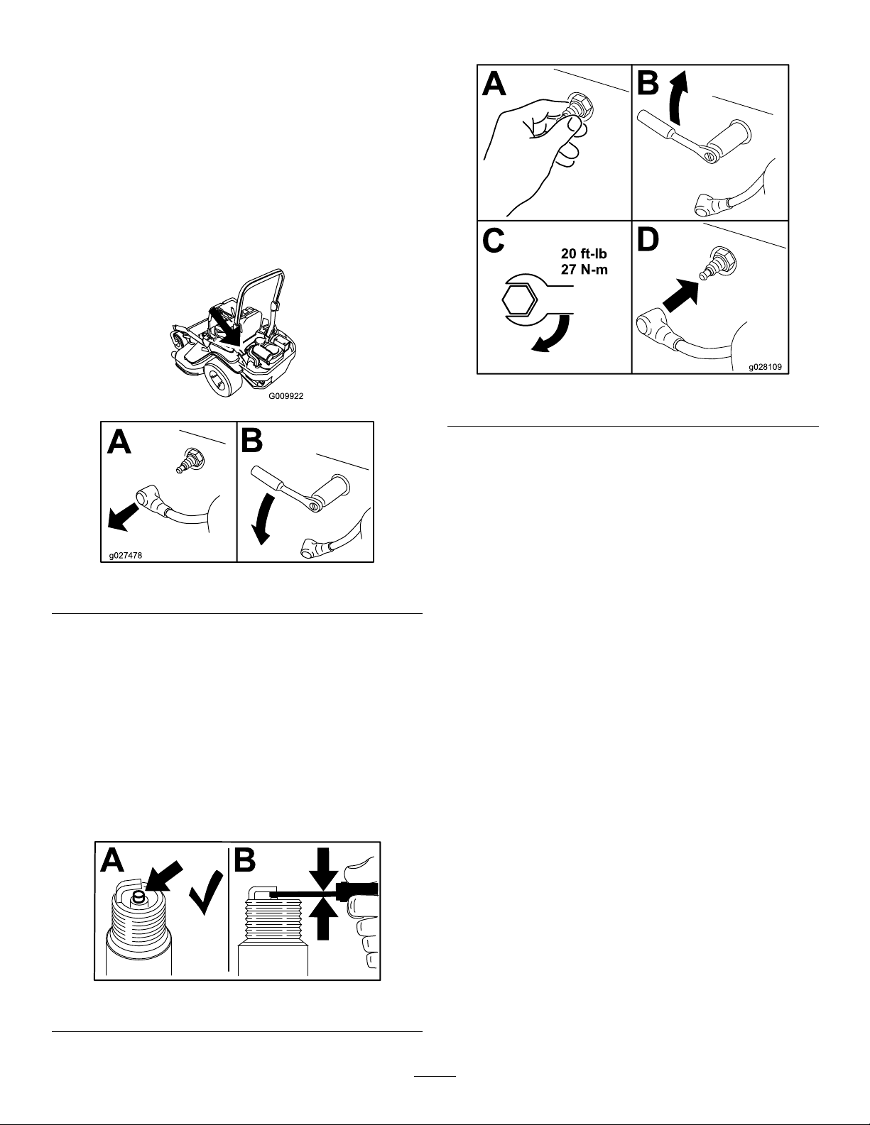
RemovingtheSparkPlug
1.Parkthemachineonalevelsurface,disengage
theblade-controlswitch(PTO),andengagethe
parkingbrake.
2.Shutofftheengine,removethekey ,andwait
forallmovingpartstostopbeforeleavingthe
operatingposition.
3.Cleantheareaaroundthebaseoftheplug(s)to
keepdirtanddebrisoutoftheengine.
4.Locateandremovethesparkplug(s)asshown
inFigure63.
InstallingtheSparkPlug
g028109
g009922
Figure65
Figure63
CheckingtheSparkPlug(s)
Important:Donotcleanthesparkplug(s).
Alwaysreplacethesparkplug(s)whenithasa
blackcoating,wornelectrodes,anoilylm,or
cracks.
Ifyouseelightbrownorgrayontheinsulator,the
engineisoperatingproperly.Ablackcoatingonthe
insulatorusuallymeanstheaircleanerisdirty .
Setthegapto0.76mm(0.030inch).
g027478
Figure64
g206628
49

CleaningtheEngineScreen
FuelSystem
ServiceInterval:Beforeeachuseordaily—Clean
theenginescreen,engine-oilcooler,
andtheareaaroundtheengine.
Beforeeachuseordaily—Cleanaroundthe
engine-exhaustsystem.
Beforeeachuseremoveanybuildupofgrass,dirt,
orotherdebrisfromtheenginescreen,engine
exhaust,engine-oilcooler,andtheareaaroundthe
engine.Thishelpsensureadequatecoolingand
correctenginespeedandreducesthepossibilityof
overheatingandmechanicaldamagetotheengine.
CheckingtheSpark
Arrester
ForMachineswithaSpark
Arrester
ServiceInterval:Every50hours
WARNING
Hotexhaust-systemcomponentsmayignite
fuelvaporsevenafteryoushutofftheengine.
Hotparticlesexhaustedduringengine
operationmayigniteammablematerials,
resultinginpersonalinjuryorproperty
damage.
Maintenance
DANGER
Incertainconditions,fuelisextremely
ammableandhighlyexplosive.Areor
explosionfromfuelcanburnyouandothers
andcandamageproperty.
RefertoFuelSafety(page15)foracomplete
listoffuelrelatedprecautions.
ReplacingtheFuelFilter
ServiceInterval:Every500hours/Yearly(whichever
comesrst)(moreoftenindusty,
dirtyconditions).
Important:Installthefuellinehosesandsecure
withplastictiesthesameastheywereoriginally
installedatthefactorytokeepthefuellineaway
fromcomponentsthatcancausefuellinedamage.
Neverinstalladirtylterafterremovingitfromthe
fuelline.
Thefuellterislocatedneartheengineontheleft
frontoftheengine.
1.Parkthemachineonalevelsurface,disengage
theblade-controlswitch(PTO),andengagethe
parkingbrake.
Donotrefuelorruntheengineunlessthe
sparkarresterisinstalled.
1.Parkthemachineonalevelsurface,disengage
thePTO,andengagetheparkingbrake.
2.Shutofftheengine,removethekey ,andwait
forallmovingpartstostopbeforeleavingthe
operatingposition.
3.Waitforthemufertocool.
4.Ifyouseeanybreaksinthescreenorwelds,
replacethearrester.
5.Ifthescreenisplugged,removethearrester,
shakelooseparticlesoutofthearrester,and
cleanthescreenwithawirebrush(soakthe
screeninsolventifnecessary).
6.Installthearresterontheexhaustoutlet.
2.Shutofftheengine,removethekey ,andwait
forallmovingpartstostopbeforeleavingthe
operatingposition.
3.Allowthemachinetocooldown.
4.Replacethefuellter(Figure66).
Note:Ensurethattheow-directionarrowon
thereplacementlterpointstowardtheengine.
50
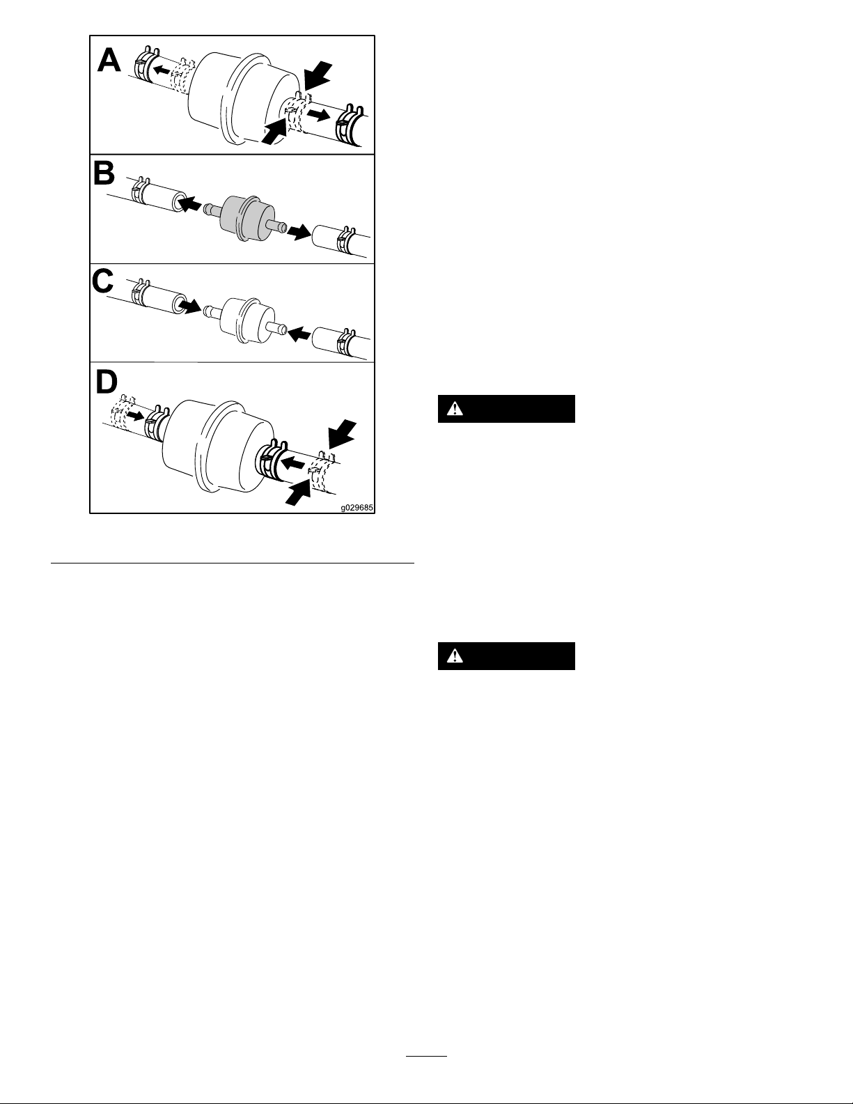
Figure66
ServicingtheFuelTank
ElectricalSystem
Maintenance
ElectricalSystemSafety
•Disconnectthecablefromthenegativeterminalof
thebatterybeforerepairingthemachine.
•Chargethebatteryinanopen,well-ventilated
area,awayfromsparksandames.Unplugthe
chargerbeforeconnectingordisconnectingthe
battery.Wearprotectiveclothinganduseinsulated
tools.
ServicingtheBattery
ServiceInterval:Monthly
RemovingtheBattery
WARNING
Batteryterminalsormetaltoolscouldshort
againstmetalmachinecomponentscausing
sparks.Sparkscancausethebatterygasses
toexplode,resultinginpersonalinjury.
g029685
•Whenremovingorinstallingthebattery,
donotallowthebatteryterminalstotouch
anymetalpartsofthemachine.
•Donotallowmetaltoolstoshortbetween
thebatteryterminalsandmetalpartsofthe
machine.
Donotattempttodrainthefueltank.Ensurethatan
AuthorizedServiceDealerdrainsthefueltankand
servicesanycomponentsofthefuelsystem.
WARNING
Incorrectlyremovingthecablesfrombattery
coulddamagethemachineandcables,
causingsparks.Sparkscancausethebattery
gassestoexplode,resultinginpersonal
injury.
•Alwaysdisconnectthenegative(black)
batterycablebeforedisconnectingthe
positive(red)cable.
•Alwaysconnectthepositive(red)battery
cablebeforeconnectingthenegative
(black)cable.
1.Parkthemachineonalevelsurface,disengage
theblade-controlswitch(PTO),andengagethe
parkingbrake.
2.Shutofftheengine,removethekey ,andwait
forallmovingpartstostopbeforeleavingthe
operatingposition.
3.RemovethebatteryasshowninFigure67.
51

ChargingtheBattery
g036853
g000960
Figure68
1.Positive(+)batterypost3.Red(+)chargerlead
2.Negative(–)batterypost4.Black(–)chargerlead
g036855
Figure67
WARNING
Chargingthebatteryproducesgassesthat
canexplode.
Neversmokenearthebatteryandkeepsparks
andamesawayfromthebattery.
Important:Alwayskeepthebatteryfullycharged
(1.265specicgravity).Thisisespecially
importanttopreventbatterydamagewhenthe
temperatureisbelow0°C(32°F).
1.Removethebatteryfromthechassis;referto
RemovingtheBattery(page51).
2.Chargethebatteryfor10to15minutesat25to
30Aorfor30minutesat10A.
Note:Donotoverchargethebattery .
3.Whenthebatteryisfullycharged,unplug
thechargerfromtheelectricaloutlet,then
disconnectthechargerleadsfromthebattery
posts(Figure68).
4.Installthebatteryinthemachineandconnect
thebatterycables;refertoInstallingtheBattery
(page53).
Note:Donotrunthemachinewiththebattery
disconnected;electricaldamagemayoccur.
52
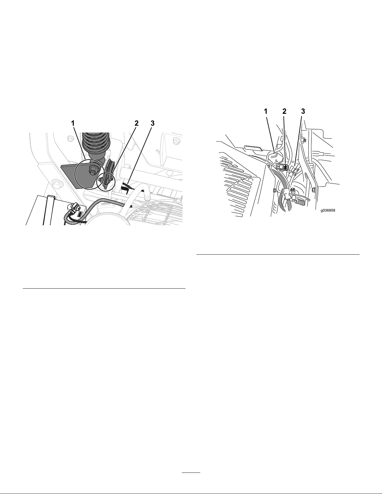
InstallingtheBattery
1.Positionthebatteryinthetraywiththeterminal
postsoppositefromthehydraulictank(Figure
67).
2.Installthepositive(red)batterycabletothe
positive(+)batteryterminal.
3.Installthenegative(black)batterycableand
groundwiretothenegative(-)batteryterminal.
Note:ForMyRidemachines,ensurethatthe
groundcabledoesnotrubagainstthetrailing
armorlowershockmount(Figure70).
ServicingtheFuses
Theelectricalsystemisprotectedbyfuses.Itrequires
nomaintenance;however,ifafuseblowscheckthe
componentandcircuitforamalfunctionorshort.
Thefusesarelocatedontherightconsolenexttothe
seat(Figure70).
1.T oreplacethefuses,pulloutthefusetoremove
it.
2.Installanewfuse(Figure70).
Figure69
1.Ensurethattheground
cabledoesnotrubagainst
thelowershockmount.
2.Ensurethattheground
cabledoesnotrubagainst
thetrailingarm.
3.Groundcable
4.Securethecableswith2bolts,2washers,and
2locknuts(Figure67).
5.Slidetheredterminalbootontothepositive(+)
batteryterminal.
6.Securethebatterywiththerubberstrap(Figure
67).
g036858
g334253
1.Fusecover
2.Fuseholder
Figure70
3.Fuel-shutoffvalve
53
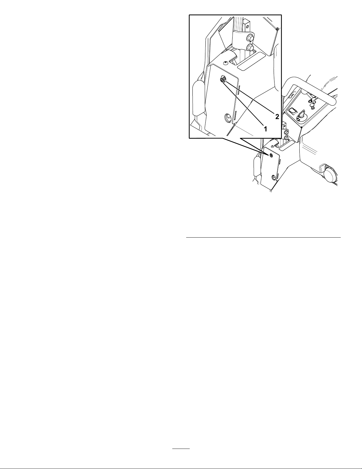
DriveSystem
Maintenance
CheckingtheSeatBelt
ServiceInterval:Beforeeachuseordaily
Inspecttheseatbeltforwear,cuts,andproper
operationoftheretractorandbuckle.Replacethe
seatbeltifitisdamaged.
AdjustingtheTracking
1.Disengagetheblade-controlswitch(PTO).
2.Drivetoanopen,atareaandmovethe
motion-controlleverstotheNEUTRAL-LOCK
position.
3.MovethethrottlemidwaybetweentheFASTand
SLOWpositions.
4.Movebothmotion-controlleversforwarduntil
theybothhitthestopsintheT-slot.
5.Checkwhichwaythemachinetracks.
6.Ifthemachinetrackstotheright,inserta3/16
inchhexwrenchthroughtheaccessholeinthe
left,frontcoverpanelandrotatethetracking
screwclockwiseorcounterclockwisetoadjust
thetravelofthelever(Figure71).
1.Trackingscrew
g334735
Figure71
Rightcontrollevershown
2.Accessholeonthefront
coverpanel
7.Ifthemachinetrackstotheleft,inserta3/16
inchhexwrenchthroughtheaccessholeinthe
right,frontcoverpanelandrotatethetracking
screwclockwiseorcounterclockwisetoadjust
thetravelofthelever(Figure71).
8.Drivethemachineandcheckthefullforward
tracking.
9.Repeattheadjustmentuntilthedesiredtracking
isobtained.
54

CheckingtheTirePressure
ForMachineswithPneumatic
TiresOnly
BrakeMaintenance
AdjustingtheParking
ServiceInterval:Every50hours/Monthly(whichever
comesrst)Formachineswith
pneumatictiresonly.
Maintaintheairpressureinthecastertiresandrear
tiresat90kPa(13psi).Uneventirepressurecan
causeunevencut.Checkthetireswhentheyarecold
togetthemostaccuratepressurereading.
Figure72
Brake
Ifyouneedtoadjusttheparkingbrake,contactan
AuthorizedServiceDealer.
g001055
CheckingtheWheelLug
Nuts
Checkandtorquethewheellugnutsto122to136
N∙m(90to100ft-lb).
55
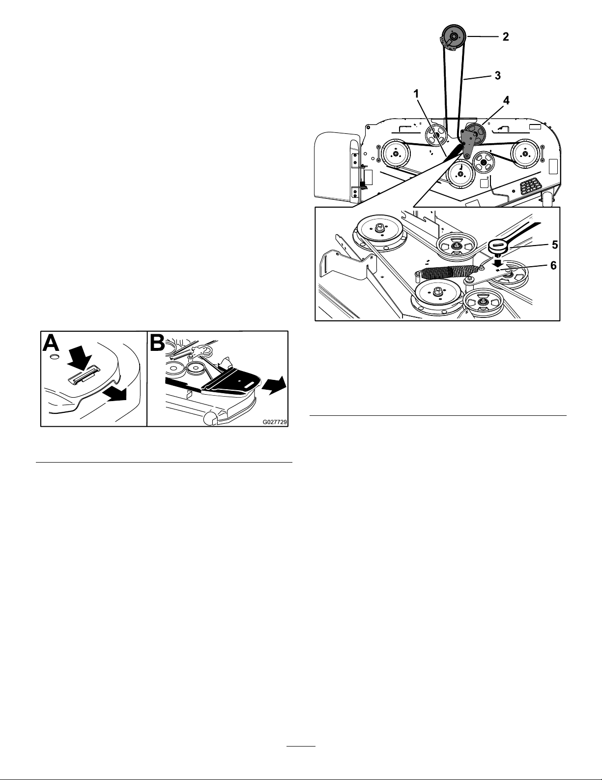
BeltMaintenance
InspectingtheBelts
ServiceInterval:Every50hours
Replacethebeltifitisworn.Thesignsofawornbelt
includesquealingwhilethebeltisrotating;theblades
slippingwhilecuttinggrass;andfrayededges,burn
marks,andcracksonthebelt.
ReplacingtheMowerBelt
1.Parkthemachineonalevelsurface,disengage
theblade-controlswitch(PTO),andengagethe
parkingbrake.
2.Shutofftheengine,removethekey ,andwait
forallmovingpartstostopbeforeleavingthe
operatingposition.
3.Lowerthemowertothe76mm(3inches)height
ofcut.
4.Removethebeltcovers(Figure73).
Figure73
5.Usea3/8-inchratchetinthesquareholeinthe
idlerarmtoremovetensionontheidlerspring
(Figure74).
6.Removethebeltfromthemower-deckpulleys
andtheclutchpulley.
7.Removethebeltguideonthespring-loaded
idlerarm(Figure74).
8.Removetheexistingbelt.
9.Installthenewbeltaroundthemowerpulleys
andtheclutchpulleyundertheengine(Figure
74).
g334846
Figure74
1.Spring4.Spring-loadedidler
2.Clutchpulley
3.Mowerbelt
g027729
10.Installthebeltguideontheidlerarm(Figure74).
11.Usingthe3/8-inchratchetinthesquarehole,
installtheidlerspring(Figure74).
assembly
5.Ratchet
6.Squareholeintheidler
armfortheratchet
Note:Ensurethatthespringendsareseated
intheanchorgrooves.
12.Installthebeltcovers(Figure75).
56
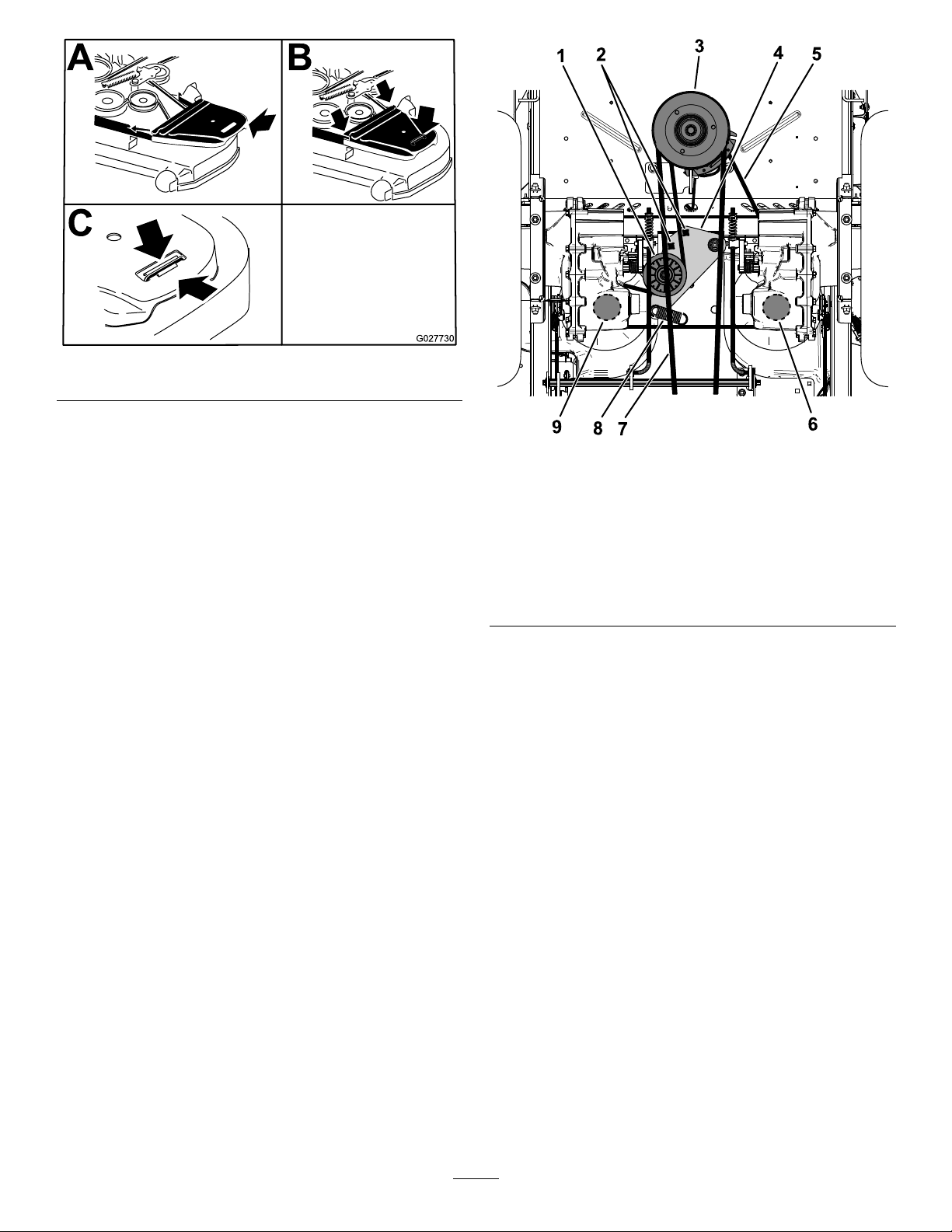
ReplacingtheHydraulic
g027730
Figure75
g334847
Figure76
Pump-DriveBelt
1.Parkthemachineonalevelsurface,disengage
theblade-controlswitch(PTO),andengagethe
parkingbrake.
2.Shutofftheengine,removethekey ,andwait
forallmovingpartstostopbeforeleavingthe
operatingposition.
3.Removethemowerbelt;refertoReplacingthe
MowerBelt(page56).
4.Raisethemachineandsupportitwithjack
stands.
5.Usea1/2-inchratchetorbreakerbarinone
ofthesquareholesintheidlerarmtoremove
tensionontheidlerspring(Figure76).
6.Removetheexistingbeltfromtheidlerpulley,2
hydraulic-pump-drivepulleys,andenginepulley
(Figure76).
7.Installthenewbeltaroundtheidlerpulley,
enginepulley,and2hydraulic-pumppulleys
(Figure76).
1.Idlerpulley6.Righthydraulic-pump
2.Squareholeintheidler
armfortheratchet
3.Enginepulley8.Idler-springpost
4.Idlerarm
5.Hydraulicpump-drivebelt
pulley
7.Mowerbelt
9.Lefthydraulic-pumppulley
8.Usingthe1/2-inchratchetorbreakerbarinone
ofthesquareholes,installtheidlerspring.
Note:Ensurethatthespringendsareseated
intheanchorgrooves.
9.Installthemowerbelt;refertoReplacingthe
MowerBelt(page56).
57

ControlsSystem
Maintenance
AdjustingtheTilt
1.Parkthemachineonalevelsurface,disengage
theblade-controlswitch(PTO),andengagethe
parkingbrake.
Adjustingthe
Control-HandlePosition
Iftheendsofthelevershitagainsteachother,referto
AdjustingtheMotion-ControlLinkage(page59).
AdjustingtheHeight
Youcanadjustthemotioncontrollevershigheror
lowerformaximumcomfort.
1.Parkthemachineonalevelsurface,disengage
theblade-controlswitch(PTO),andengagethe
parkingbrake.
2.Shutofftheengine,removethekey ,andwait
forallmovingpartstostopbeforeleavingthe
operatingposition.
3.Removethehardwareholdingthecontrollever
tothecontrol-armshaft.
2.Shutofftheengine,removethekey ,andwait
forallmovingpartstostopbeforeleavingthe
operatingposition.
3.Loosentheupperboltholdingthecontrollever
tothecontrolarmshaft.
4.Loosenthelowerboltjustenoughtopivotthe
controlleverforeoraft.Tightenbothboltsto
securethecontrolinthenewposition.
5.Repeattheadjustmentfortheoppositecontrol
lever.
Figure77
1.Bolts
2.Slottedhole4.Control-armshaft
4.Movethecontrollevertothenextsetofholes.
Securetheleverwiththehardware.
5.Repeattheadjustmentfortheoppositecontrol
lever.
3.Controllever
g009195
Figure78
g035858
58

Adjustingthe
Motion-ControlLinkage
Locatedoneithersideofthemachine,belowtheseat,
arethepump-controllinkages.Rotatingtheendnut
witha1/2-inchdeepsocketwrenchallowsnetuning
adjustmentssothatthemachinedoesnotmovein
neutral.Anyadjustmentsshouldbemadeforneutral
positioningonly.
WARNING
Theenginemustberunningandthedrive
wheelsturningsothatyoucanperformthe
adjustments.Contactwithmovingpartsor
hotsurfacesmaycausepersonalinjury .
Keepyourngers,hands,andclothingclear
ofrotatingcomponentsandhotsurfaces.
1.Parkthemachineonalevelsurface,disengage
theblade-controlswitch(PTO),andengagethe
parkingbrake.
2.Shutofftheengine,removethekey ,andwait
forallmovingpartstostopbeforeleavingthe
operatingposition.
3.Pushthedeck-liftpedal,removetheheight-of-cut
pin,andlowerthemowerdecktotheground
4.Raisetherearofthemachineupandsupportit
withjackstands(orequivalentsupport)justhigh
enoughtoallowthedrivewheelstoturnfreely.
5.Removetheelectricalconnectionfromtheseat
safetyswitch,locatedunderthebottomcushion
oftheseat.
11.Adjustthepump-control-rodlengthsbyrotating
thenutintheappropriatedirectionuntilthe
wheelsslightlycreepinreverse(Figure79and
Figure80).
g334848
Figure79
1.Accessholefor1/2-inchsocket
Note:Theswitchisapartoftheseatassembly .
6.T emporarilyinstallajumperwireacrossthe
terminalsintheconnectorofthemainwire
harness.
7.Starttheengine,runitatfullthrottle,and
disengagetheparkingbrake.
Note:Beforestartingtheengine,ensurethat
theparkingbrakeisengagedandthatthe
motion-controlleversareout.Youdonothave
tobeintheseat.
8.Runthemachineatleast5minuteswiththe
driveleversatfullforwardspeedtobringthe
hydraulicuiduptotheoperatingtemperature.
Note:Themotion-controlleversmustbein
neutralwhileyouaremakinganyadjustments.
9.Bringthemotion-controlleversintotheNEUTRAL
position.
10.Checkandensurethatthecontrol-platetabs
touchthereturn-to-neutralplatesonthe
hydraulicunits.
Figure80
1.Nut4.Return-to-neutralplate
2.Stationaryplate
3.Controlplate
12.Movethemotion-controlleverstotheREVERSE
positionandwhileapplyingslightpressureto
thelever,allowthereverse-indicatorspringsto
bringtheleversbacktoneutral.
5.Tabstouchingreturnto
neutralplate
g036753
59

Note:Thewheelsshouldstopturningorslightly
creepinreverse.
HydraulicSystem
Note:Youmayneedtoremovethe
motion-controlcovertogainaccess.
13.Shutoffthemachine.
14.Removethejumperwirefromthewireharness
andplugtheconnectorintotheseatswitch.
15.Removethejackstands.
16.Raisethemowerdeckandinstallthe
height-of-cutpin.
17.Checkandensurethatthemachinedoes
notcreepinneutralwiththeparkingbrake
disengaged.
Maintenance
HydraulicSystemSafety
•Seekimmediatemedicalattentionifuidisinjected
intoskin.Injecteduidmustbesurgicallyremoved
withinafewhoursbyadoctor.
•Ensurethatallhydraulic-uidhosesandlinesare
ingoodconditionandallhydraulicconnections
andttingsaretightbeforeapplyingpressureto
thehydraulicsystem.
•Keepyourbodyandhandsawayfrompinhole
leaksornozzlesthatejecthigh-pressurehydraulic
uid.
•Usecardboardorpapertondhydraulicleaks.
•Safelyrelieveallpressureinthehydraulicsystem
beforeperforminganyworkonthehydraulic
system.
Hydraulic-Fluid
Specications
HydraulicFluidType:Toro
hydraulicuid
Important:Usethespecieduid.Otheruids
coulddamagethehydraulicsystem.
ZT4400HydrosHydraulicSystemCapacity(with
ltersremoved):7.57L(8USqt)
ZT5400HydrosHydraulicSystemCapacity(with
ltersremoved):9.46L(10USqt)
®
HYPR-OIL
™
500
60

Checkingthe
ChangingtheHydraulic
Hydraulic-FluidLevel
ServiceInterval:Beforeeachuseordaily
1.Allowthehydraulicuidtocooldown.Checkthe
oillevelwhentheuidiscold.
2.Checkexpansionreservoirandifnecessary
addT oro
FULLCOLDline(Figure81).
®
HYPR-OIL
™
500hydraulicuidtothe
FluidandFilters
ServiceInterval:Aftertherst100hours—Change
thehydraulic-systemltersand
uid.
Every400hoursoryearly,whichevercomes
rst—Aftertheinitialchange—changethe
hydraulic-systemltersanduidwhenusing
®
Toro
oftenunderdirtyordustyconditions).
Toreplacethehydraulicuid,theltersneedtobe
removed.Replacebothatthesametime;referto
Hydraulic-FluidSpecications(page60)foruid
specications.
Purgeanyairinthesystemafteryouinstallthenew
ltersandadduid.RefertoBleedingtheHydraulic
System(page63).Repeatthebleedingprocessuntil
theuidremainsattheFULLCOLDlineinthereservoir
afterpurging.
HYPR-OIL
Important:Failuretoproperlyperformthis
procedurecanresultinirreparabledamagetothe
transaxledrivesystem.
™
500uid(changeitmore
Figure81
1.Expansiontank2.Engine
RemovingHydraulicFluidand
g334849
Filters
Thisprocedurevariesdependingonthedrivesystem
ofthemodel.Ifitisunclearwhichdrivesystemison
themodel,contactyourAuthorizedServiceDealer.
1.Parkthemachineonalevelsurface,disengage
theblade-controlswitch(PTO),andengagethe
parkingbrake.
2.Shutofftheengine,removethekey ,andwait
forallmovingpartstostopbeforeleavingthe
operatingposition.
3.Allowtheenginetocool.
4.Locateandremovetheventplugasfollows:
Note:Ensurethatyoukeeptrackofthevent
plugafterremoval,asitcanbeeasytomisplace.
•ForZT4400Hydros,useanextensionand
7/16-inchsocket,accesstheventplugfrom
thetopofthemachinethroughtheholes
neartheroll-barmounts(Figure82).
61

Figure82
1.Accessholesfortheventplugs
•ForZT5400Hydros,usea7/16-inchwrench
toaccesstheventplugfromunderneaththe
machine(Figure83).
6.Placeadrainpanbelowtheltertocatchthe
uidthatdrainswhenthelterandventplugs
areremoved.
7.Removethehydraulic-uidltercoverfromthe
transaxletodraintheuid(Figure84).
g336998
g334915
Figure84
1.Hydraulic-lterhousing2.Cover
1.Ventplug
Figure83
8.RemovetheO-ringfromtheltercoverand
discardtheO-ring.
9.Afterthehydraulicuiddrainsfromthetransaxle,
removethelterfromthetransaxlehousing.
10.Repeatthisprocedureontheothersideofthe
machine.
InstallingtheHydraulicFluidand
Filters
1.Installanewlterinthetransaxleandanew
O-ringontotheltercover.
2.Installtheltercover.
3.T orquetheltercoverasfollows:
•ZT4400Hydros:22.6to33.8N∙m(200to
300in-lb)
•ZT5400Hydros:54.3to65.5N∙m(480to
g336999
4.Removethecapfromtheexpansiontankandll
580in-lb)
thetransaxleswiththespecieduiduntilthe
properuidcapacitiesaremet.
5.Carefullycleantheareaaroundthelter.
Important:Donotallowdirttoenterthe
hydraulicsystem;otherwise,contamination
mayoccur.
Note:Fillingthetransaxlesmaytakemoretime
thanexpected.
5.Installthepreviouslyremovedventplugsand
torquetheplugsto395to904N∙cm(35to80
in-lb).
6.ProceedtoBleedingtheHydraulicSystem
(page63).
62

Important:FailuretoperformtheBleeding
theHydraulicSystemprocedureafter
changinghydraulicltersanduidcan
resultinirreparabledamagetothetransaxle
drivesystem.
BleedingtheHydraulic
System
1.Raisetherearofmachineandsupportitwith
jackstands(orequivalentsupport)justhigh
enoughtoallowthedrivewheelstoturnfreely.
4.Checktheuidlevelintheexpansionreservoir
analtime.Addthespecieduidasuntilit
reachestheFULLCOLDlineontheexpansion
reservoir.
Figure85
1.Jackingpoints
2.Starttheengine,movethethrottlecontrolahead
tothe1/2throttleposition,anddisengagethe
parkingbrake.
A.Movethebypassleversintothepushingthe
machineposition.Withthebypassvalves
openandtheenginerunning,slowlymove
themotion-controlleversinbothforward
andreverse5or6times.
B.Movethebypassleversintotheoperating
themachineposition.
C.Withthebypassvalveclosedandthe
enginerunning,slowlymovethecontrol
leverinbothforwardandreversedirections
5to6times.
D.Shutofftheengineandchecktheuid
levelintheexpansionreservoir.Addthe
specieduiduntilitreachestheFULLCOLD
lineontheexpansionreservoir.
g017625
3.Repeatstep2untilalltheairiscompletely
purgedfromthesystem.
Note:Whenthetransaxleoperatesatnormal
noiselevels,movessmoothlyforward,and
reversesatnormalspeeds,itispurged.
63

MowerDeck
Maintenance
BladeSafety
•Inspectthebladesperiodicallyforwearordamage.
•Usecarewhencheckingtheblades.Wrapthe
bladesorweargloves,andusecautionwhen
servicingtheblades.Onlyreplaceorsharpenthe
blades;neverstraightenorweldthem.
•Onmulti-bladedmachines,takecareasrotating
onebladecancauseotherbladestorotate.
•Replacewornordamagedbladesandboltsinsets
topreservebalance.
ServicingtheCutting
Blades
Toensureasuperiorqualityofcut,keeptheblades
sharp.Forconvenientsharpeningandreplacement,
youmaywanttokeepextrabladesonhand.
BeforeInspectingorServicingthe
Blades
1.Parkthemachineonalevelsurface,disengage
theblade-controlswitch(PTO),andengagethe
parkingbrake.
g006530
Figure86
1.Cuttingedge3.Wear/slotforming
2.Curvedarea4.Crack
2.Shutofftheengine,removethekey,and
disconnectthespark-plugwiresfromthespark
plugs.
InspectingtheBlades
ServiceInterval:Beforeeachuseordaily
1.Inspectthecuttingedges(Figure86).
2.Iftheedgesarenotsharporhavenicks,remove
andsharpentheblade;refertoSharpeningthe
Blades(page66).
3.Inspecttheblades,especiallyinthecurvedarea.
4.Ifyounoticeanycracks,wear,oraslotforming
inthisarea,immediatelyinstallanewblade
(Figure86).
64
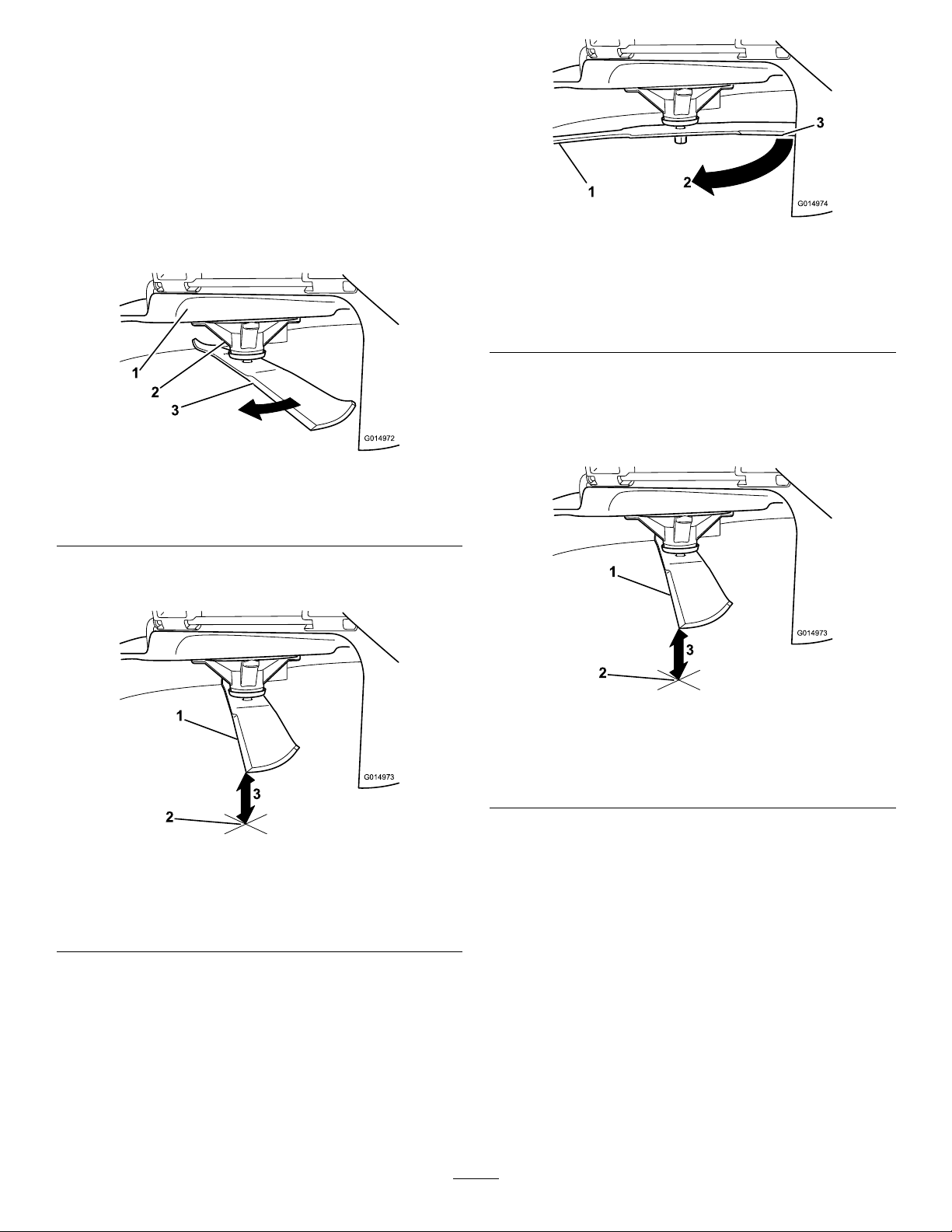
CheckingforBentBlades
Note:Themachinemustbeonalevelsurfacefor
thefollowingprocedure.
1.Raisethemowerdecktothehighest
height-of-cutposition.
2.Whilewearingthicklypaddedgloves,orother
adequatehandprotection,slowlyrotatethe
bladeintoapositionthatallowsyoutomeasure
thedistancebetweenthecuttingedgeandthe
levelsurfacethemachineison(Figure87).
Figure87
1.Deck3.Blade
2.Spindlehousing
g014974
Figure89
1.Blade(sidepreviouslymeasured)
2.Measurement(positionusedpreviously)
3.Opposingsideofbladebeingmovedintomeasurement
position
5.Measurefromthetipofthebladetotheat
surface(Figure90).
Note:Thevarianceshouldbenomorethan
g014972
3mm(1/8inch).
3.Measurefromthetipofthebladetotheat
surface(Figure88).
Figure88
1.Blade(inpositionformeasuring)
2.Levelsurface
3.Measureddistancebetweenbladeandthesurface(A)
4.Rotatethesameblade180degreessothat
theopposingcuttingedgeisnowinthesame
position(Figure89).
g014973
Figure90
1.Oppositebladeedge(inpositionformeasuring)
2.Levelsurface
3.Secondmeasureddistancebetweenbladeandsurface(B)
g014973
A.IfthedifferencebetweenAandBisgreater
than3mm(1/8inch),replacethebladewith
anewblade;refertoRemovingtheBlades
(page66)andInstallingtheBlades(page
66).
Note:Ifabentbladeisreplacedwitha
newblade,andthedimensionobtained
continuestoexceed3mm(1/8inch),the
bladespindlecouldbebent.Contactan
AuthorizedServiceDealerforservice.
B.Ifthevarianceiswithinconstraints,moveto
thenextblade.
6.Repeatthisprocedureoneachblade.
65

RemovingtheBlades
Replacethebladesiftheyhitasolidobject,orifthe
bladeisoutofbalanceorbent.
1.Placeawrenchontheatofthespindleshaftor
holdthebladeendusingaragorthicklypadded
glove.
2.Removethebladebolt,bushing,andbladefrom
thespindleshaft(Figure91).
Note:Ifthebladestaysinahorizontalposition,
thebladeisbalancedandcanbeused.
Note:Ifthebladeisnotbalanced,lesome
metalofftheendofthesailareaonly(Figure92).
g000553
Figure93
1.Blade2.Balancer
3.Repeatthisprocedureuntilthebladeis
balanced.
InstallingtheBlades
1.Installthebushingthroughthebladewiththe
bushingangeonthebottom(grass)sideofthe
blade(Figure94).
Figure91
1.Sailareaoftheblade
2.Blade5.Bladebolt
3.Flatofthespindleshaft
4.Bushing
SharpeningtheBlades
1.Usealetosharpenthecuttingedgeatboth
endsoftheblade(Figure92).
Note:Maintaintheoriginalangle.
Note:Thebladeretainsitsbalanceifthesame
amountofmaterialisremovedfrombothcutting
edges.
Figure92
g295816
g255205
Figure94
1.Bushing
2.Installthebushing/bladeassemblyintothe
spindleshaft(Figure95).
g000552
1.Sharpenatoriginalangle.
2.Checkthebalanceofthebladebyputtingitona
bladebalancer(Figure93).
66

Figure95
1.Topspindlenut3.Bladebolt
2.Flatofthespindleshaft
3.Applycopper-basedlubricantorgreasetothe
threadsofthebladeboltasneededtoprevent
seizing.Installthebladeboltnger-tight.
4.Placeawrenchontheatofthespindleshaft
andtorquethebladeboltto75to81N∙m(55
to60ft-lb).
AdjustingtheSide-to-Side
LevelingandtheBlade
Slope
Checktoensurethatthemowerdeckislevelanytime
youinstallthemowerorwhenyouseeanunevencut
onyourlawn.
Checkthemowerdeckforbentbladespriorto
leveling,andremoveandreplaceanybentblades;
refertoServicingtheCuttingBlades(page64)before
continuing.
Levelthemowerdeckside-to-siderst;thenyoucan
adjustthefront-to-rearslope.
Requirements:
g298850
•Themachinemustbeonalevelsurface.
•Alltiresmustbeproperlyinated;refertoChecking
theTirePressure(page55).
1.Parkthemachineonalevelsurface,disengage
theblade-controlswitch(PTO),andengagethe
parkingbrake.
2.Shutofftheengine,removethekey ,andwait
forallmovingpartstostopbeforeleavingthe
operatingposition.
3.Checkthetirepressureinthedrivetires;referto
CheckingtheTirePressure(page55).
4.Positionthemowerdeckinthetransport-lock
positionorthehighestheight-of-cutsetting.
5.Carefullyrotatethebladesfromsidetoside.
6.Measurebetweenthebladetipandtheat
surface(Figure96).Ifbothmeasurementsare
notwithin5mm(3/16inch),adjusttheleveling;
continuewiththisprocedure.
Figure96
1.Bladessidetoside
2.Bladetip
3.Measurefromthetipofthe
bladetotheatsurface
here.
g037879
67
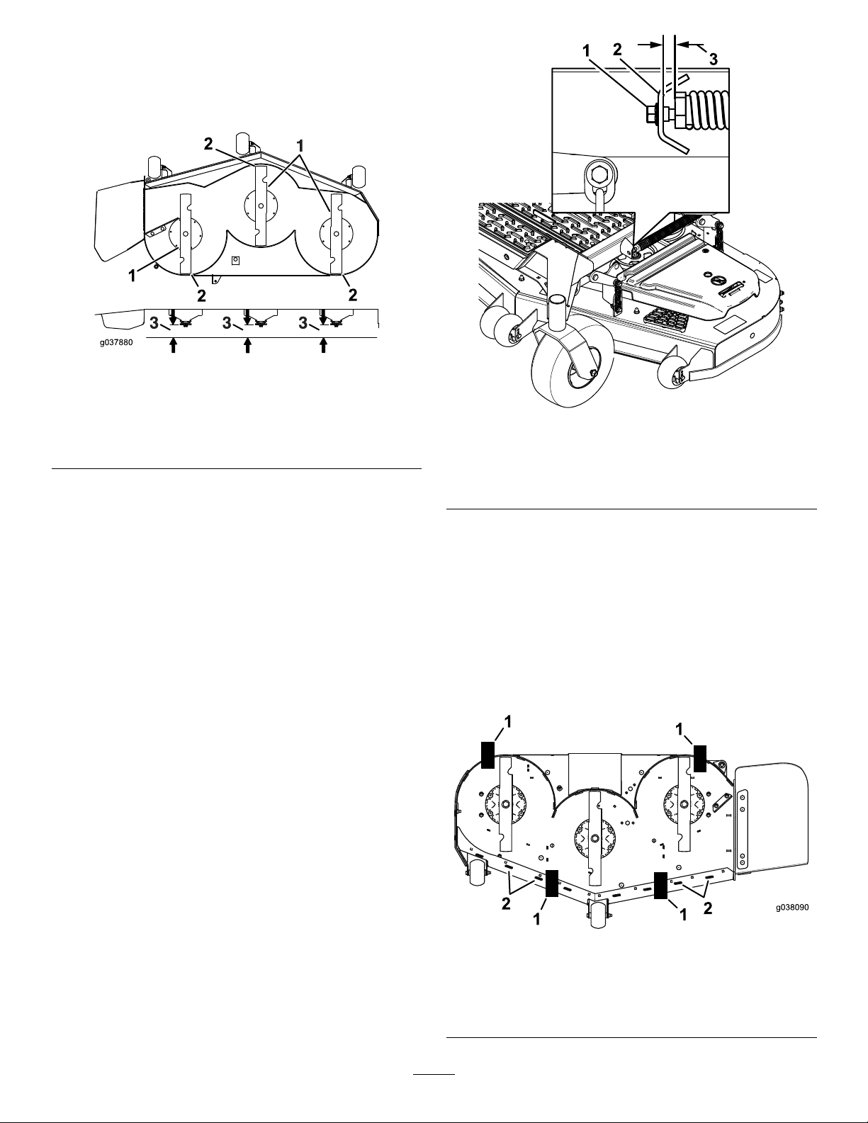
7.Checkthefront-to-rearbladelevel(Figure97).
Ensurethefrontbladetipislowerthantherear
bladetipasshownintheblockheightandrake
table.Ifadjustmentisneeded,continuewiththis
procedure.
Figure97
g037880
1.Bladesfronttorear3.Measurefromthetipofthe
bladetotheatsurface
here.
2.Bladetip
8.Settheanti-scalprollerstotopholesorremove
themcompletelyforthisadjustment.
9.Raisethedecktothetransportposition(140mm
or5-1/2inches).
10.Slowlyloosentheadjustingscrewonthe
lift-assistspringuntilyoucanremovethescrew
(Figure98).
Note:Savethescrewforinstallation.
Figure98
1.Adjustingscrew
2.Bracket
3.Setthegapto22to29
mm(7/8to1-1/8inches).
11.Place2blocks(seeBlockHeightandRake
Table)undertherearedgeofthecuttingdeck
skirt;1oneachsideofthecuttingdeck(Figure
99).
12.Settheheight-of-cutlevertothe76mm(3
inches)position;refertoAdjustingtheHeight
ofCut(page28).
13.Place2blocksundereachsideofthefrontedge
ofthedeck,butnotundertheanti-scalproller
bracketsorwelds.
g334850
1.Block—73mm(2-7/8
68
g038090
Figure99
Bottomview
2.Welds
inches)
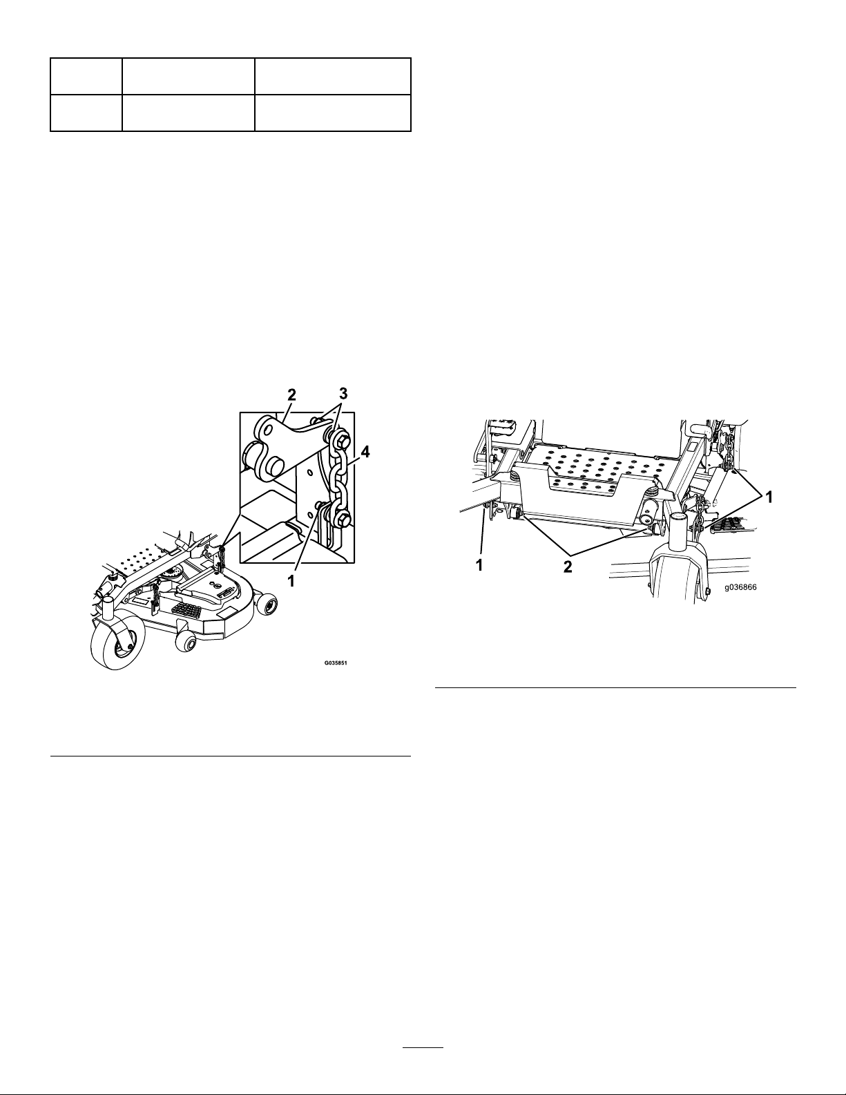
BlockHeightandRakeTable
Deck
Size
Allmower
decks
14.Carefullyrotatethebladessidetoside(Figure
96).
15.Lowerthemowerdecktothe76mm(3inches)
position;refertoAdjustingtheHeightofCut
(page28).
16.Loosenthelocknuts(Figure100)onall4
cornersandensurethatthemowerdeckis
sittingsecurelyonall4blocks.
17.Removeanyslackfromthedeckhangersand
makesurethedeck-liftfootleverispushedback
againstthestop.
18.Tightenthe4locknuts.
FrontBlockHeightRake
73mm(2-7/8inches)4.8to6.4mm(3/16to1/4
inch)
RemovingtheMowerDeck
Beforeservicingorremovingthemowerdeck,lock
outthespring-loadeddeckarms.
1.Parkthemachineonalevelsurface,disengage
theblade-controlswitch(PTO),andengagethe
parkingbrake.
2.Shutofftheengine,removethekey ,andwait
forallmovingpartstostopbeforeleavingthe
operatingposition.
3.Placetheheight-adjustmentpininthe7.6cm(3
inch)cutting-heightlocation.
4.Removethebeltcovers.
5.Loosenthemowerdeckidlerandremovethe
mowerbelt;refertoBeltMaintenance(page56).
6.Removetheboltsandnutsfromthefrontofthe
plateunderthefootrest.
7.Removeandretaintheboltsandnutsonboth
sidesofthemachine(Figure101).
Figure100
1.Locknuts3.Deckhanger
2.Deckliftarm4.Chain
19.Ensurethattheblockstsnuglyunderthedeck
skirtandthatallattachmentboltsaretight
20.Continuelevelingthedeckbycheckingthe
front-to-rearbladeslope.
21.Checkthebladesforlevelnessandrepeatdeck
levelingprocedureifnecessary.
22.Raisethedecktothetransportposition(140mm
or5-1/2inches).
23.Installthelift-assistspringadjustingscrew
previouslyremovedinstep10.
24.Setthegapbetweenthespringandthebracket
to22to29mm(7/8to1-1/8inches).
g036866
Figure101
1.Removethenutsandboltshere.
g035851
2.Removethenutsandboltshere.
8.Slidethedeckouttotherightsideofthe
machine.
69

ReplacingtheGrass
Deector
Cleaning
WARNING
Anuncovereddischargeopeningcouldallow
themachinetothrowobjectstowardyouor
bystanders,resultinginseriousinjury.Also,
contactwiththebladecouldoccur.
Neveroperatethemachineunlessyouinstall
amulchplate,dischargedeector,orgrass
collectionsystem.
1.Removethelocknut,bolt,spring,andspacer
holdingthedeectortothepivotbrackets
(Figure102).
2.Removethedamagedorworngrassdeector
(Figure102).
CleaningundertheMower
Deck
ServiceInterval:Aftereachuse
1.Parkthemachineonalevelsurface,disengage
theblade-controlswitch(PTO),andengagethe
parkingbrake.
2.Shutofftheengine,removethekey ,andwait
forallmovingpartstostopbeforeleavingthe
operatingposition.
3.RaisethemowerdecktotheTRANSPORT
position.
CleaningtheSuspension
System
MachineswithMyRide™
SuspensionSystemOnly
ServiceInterval:Beforeeachuseordaily
Figure102
1.Bolt
2.Spacer6.Grassdeector
3.Locknut
4.Spring
3.Placethespacerandthespringontograss
deector.
4.Place1J-hookendofthespringbehindthe
deckedge.
Note:Makesurethat1J-hookendofthe
springisinstalledbehindthedeckedgebefore
installingtheboltasshowninFigure102.
5.Installtheboltandthenut.
6.Place1J-hookendofthespringaroundthe
grassdeector(Figure102).
5.Springinstalled
7.J-hookendofspring
Usecompressedairtocleanthesuspensionsystem.
Note:Donotcleantheshockassemblieswith
pressurizedwater(Figure103).
g015594
g030538
Figure103
DisposingofWaste
Engineoil,batteries,hydraulicuid,andengine
coolantarepollutantstotheenvironment.Disposeof
theseaccordingtoyourstateandlocalregulations.
Important:Thegrassdeectormustbeable
torotate.Liftthedeectoruptothefullopen
positionandensurethatitrotatesintothe
fulldownposition.
70

Storage
StorageSafety
•Shutofftheengine,removethekey,andwait
forallmovingpartstostopbeforeyouleavethe
operator’sposition.Allowthemachinetocool
beforeadjusting,servicing,cleaning,orstoringit.
•Donotstorethemachineorfuelnearamesor
drainthefuelindoorsorinsideanenclosedtrailer.
•Donotstorethemachineorfuelcontainerwhere
thereisanopename,spark,orpilotlight,such
asonawaterheateroronotherappliances.
12.Checktheconditionoftheblades;referto
ServicingtheCuttingBlades(page64).
13.Preparethemachineforstoragewhennon-use
occursover30days.Preparethemachinefor
storageasfollows:
A.Addapetroleum-based
stabilizer/conditionertofuelinthe
tank.Followmixinginstructionsfrom
thestabilizermanufacturer.Donotuse
analcohol-basedstabilizer(ethanolor
methanol).
Note:Afuelstabilizer/conditionerismost
effectivewhenmixedwithfreshfueland
usedatalltimes.
CleaningandStorage
1.Disengagetheblade-controlswitch(PTO),and
engagetheparkingbrake.
2.Shutofftheengine,removethekey ,andwait
forallmovingpartstostopbeforeleavingthe
operatingposition.
3.Removegrassclippings,dirt,andgrimefromthe
externalpartsoftheentiremachine,especially
theengineandhydraulicsystem.Cleandirtand
chafffromtheoutsideoftheenginecylinder
headnsandblowerhousing.
Important:Youcanwashthemachinewith
milddetergentandwater.Donotpressure
washthemachine.Avoidexcessiveuse
ofwater,especiallynearthecontrolpanel,
engine,hydraulicpumps,andmotors.
4.Checktheparkingbrakeoperation;referto
AdjustingtheParkingBrake(page55).
5.Servicetheaircleaner;refertoServicingtheAir
Cleaner(page40).
6.Greasethemachine;refertoLubrication(page
37).
7.Changethecrankcaseoil;refertoEngine
Maintenance(page39).
8.Checkthetirepressure;refertoCheckingthe
TirePressure(page55).
9.Changethehydrauliclters;refertoChanging
theHydraulicFluidandFilters(page61).
B.Runtheenginetodistributeconditionedfuel
throughthefuelsystemfor5minutes.
C.Shutofftheengine,allowittocool,and
drainthefueltank.
D.Starttheengineandrunituntilitstops.
E.Disposeoffuelproperly.Recyclethefuel
accordingtolocalcodes.
Important:Donotstorefuelcontaining
stabilizer/conditionerlongerthan
thedurationrecommendedbythe
fuel-stabilizermanufacturer.
14.Removeandchecktheconditionofthespark
plug(s);refertoEngineMaintenance(page39).
Withthesparkplug(s)removedfromtheengine,
pour30ml(2tablespoons)ofengineoilintothe
sparkplughole.Usethestartertocrankthe
engineanddistributetheoilinsidethecylinder.
Installthesparkplug(s).Donotinstallthewire
onthesparkplug(s).
15.Checkandtightenallbolts,nuts,andscrews.
Repairorreplaceanypartthatisdamaged.
16.Paintallscratchedorbaremetalsurfaces.Paint
isavailablefromyourAuthorizedServiceDealer.
17.Storethemachineinaclean,drygarageor
storagearea.Removethekeyfromtheswitch
andkeepitoutofreachofchildrenorother
unauthorizedusers.Coverthemachineto
protectitandkeepitclean.
10.Chargethebattery;refertoChargingtheBattery
(page52).
11.Scrapeanyheavybuildupofgrassanddirt
fromtheundersideofthemower,thenwashthe
mowerwithagardenhose.
Note:Runthemachinewiththeblade-control
switch(PTO)engagedandtheengineathigh
idlefor2to5minutesafterwashing.
71

Troubleshooting
Problem
Theengineoverheats.
Themalfunction-indicatorlight(MIL)
comeson.
PossibleCauseCorrectiveAction
1.Theengineloadisexcessive.1.Reducethegroundspeed.
2.Theoillevelinthecrankcaseislow.2.Addoiltothecrankcase.
3.Thecoolingnsandairpassages
undertheengine-blowerhousingare
plugged.
4.Theaircleanerisdirty.
5.Dirt,water,orstalefuelisinthefuel
system.
1.Theengineistoohot.
2.Thereisoldfuelinthefueltank.2.Usenewfuel.
3.Thefuel-shutoffvalveisnotopen
completely.
4.Theaircleanerisdirty.4.Makesurethattheaircleanerand
5.Thebatteryisnotcharged.
6.Incorrectfuelltersarebeingusedor
thefuelltersaredirty.
7.Theconnectionstothesensors
electronic-controlunit(ECU)andfuel
injectorsarenotsecuredproperly .
8.Thereislowvoltagefromthebattery.
9.Afuseisblown.9.Checkandreplaceanyblownfuses.
3.Removetheobstructionfromthe
coolingnsandairpassages.
4.Cleanorreplacetheair-cleaner
element.
5.ContactanAuthorizedServiceDealer
1.Shutofftheengineandletitcool.
3.Openthefuel-shutoffvalve.
precleanerareclean.Replaceif
necessary.
5.Chargeorreplacethebattery.
6.ContactanAuthorizedServiceDealer.
7.ContactanAuthorizedServiceDealer.
8.Ensurethatyouareusingagood12V
batteryandthatitisfullycharged.
Thestarterdoesnotcrank.
1.Theblade-controlswitchisengaged.1.Disengagetheblade-controlswitch.
2.Theparkingbrakeisdisengaged.2.Engagetheparkingbrake.
3.Themotion-controlleversarenotin
theNEUTRAL-LOCKposition.
4.Y ouarenotsittingintheoperator’s
seat.
5.Thebatteryisdead.
6.Theelectricalconnectionsare
corrodedorloose.
7.Afuseisblown.7.Replacethefuse.
8.Arelayorswitchisdamaged.
3.Movethemotion-controllevers
outwardtotheNEUTRAL-LOCKposition.
4.Sitontheoperator’sseat.
5.Chargethebattery.
6.Checktheelectricalconnectionsfor
goodcontact.
8.ContactanAuthorizedServiceDealer.
72

Problem
PossibleCauseCorrectiveAction
Theenginedoesnotstart,startshard,or
failstokeeprunning.
Theenginelosespower.
1.Thefueltankisempty.1.Fillthefueltank.
2.Thefuel-shutoffvalveisclosed.2.Openthefuel-shutoffvalve.
3.Theoillevelinthecrankcaseislow.3.Addoiltothecrankcase.
4.Thethrottleisnotinthecorrect
position.
5.Thereisdirtinthefuellter.5.Replacethefuellter.
6.Thereisdirt,water,orstalefuelisin
thefuelsystem.
7.Theaircleanerisdirty.
8.Theseatswitchisnotfunctioning
properly.
9.Theelectricalconnectionsare
corroded,loose,ordamaged.
10.Therelayorswitchiswornor
damaged.
11.Thesparkplugisfouledorimproperly
gapped.
12.Thespark-plugwireisnotconnected.
1.Theengineloadisexcessive.1.Reducethegroundspeed.
2.Theaircleanerisdirty.
3.Theoillevelinthecrankcaseislow.3.Addoiltothecrankcase.
4.Thecoolingnsandtheairpassages
abovetheengineareplugged.
5.Theventholeinthefuelcapisplugged.5.Cleanorreplacethefuelcap.
6.Thereisdirtinthefuellter.6.Replacethefuellter.
7.Thereisdirt,water,orstalefuelinthe
fuelsystem.
4.Besurethatthethrottlecontrolis
midwaybetweentheSLOWandFAST
positions.
6.ContactanAuthorizedServiceDealer.
7.Cleanorreplacetheair-cleaner
element.
8.Checktheseat-switchindicator .
Replacetheseatifnecessary .
9.Checktheelectricalconnections
forgoodcontact.Cleanthe
connectorterminalsthoroughlywith
electrical-contactcleaner,apply
dielectricgrease,andmakethe
appropriateconnections.
10.ContactanAuthorizedServiceDealer.
11.Adjustorreplacethesparkplug.
12.Checkthespark-plugwireconnection.
2.Cleantheair-cleanerelement.
4.Removetheobstructionfromthe
coolingnsandtheairpassages.
7.ContactanAuthorizedServiceDealer.
Themachinepullstotheleftorright(with
themotion-controlleversfullyforward).
Themachinedoesnotdrive.
Themachinevibratesabnormally .
1.Thetrackingneedsadjustment1.Adjustthetracking.
2.Thetirepressureinthedrivetiresis
notcorrect.
1.Thebypassvalvesarenotclosedtight.1.Tightenthebypassvalves.
2.Thepumpbeltisworn,loose,or
broken.
3.Thepumpbeltisoffapulley .3.Changethebelt.
4.Theidlerspringisbrokenormissing.4.Replacethespring.
5.Thehydraulicuidlevelislowortoo
hot.
1.Thecuttingblade(s)is/arebentor
unbalanced.
2.Theblademountingboltisloose.2.Tightentheblademountingbolt.
3.Theenginemountingboltsareloose.3.Tightentheenginemountingbolts.
4.Theenginepulley ,idlerpulley,orblade
pulleyisloose.
5.Theenginepulleyisdamaged.
6.Thebladespindleisbent.
7.Themotormountislooseorworn.
2.Adjustthetirepressureinthedrive
tires.
2.Changethebelt.
5.Addhydraulicuidtothereservoirsor
letitcooldown.
1.Installnewcuttingblade(s).
4.Tightentheappropriatepulley.
5.
ContactanAuthorizedServiceDealer.
6.ContactanAuthorizedServiceDealer.
7.ContactanAuthorizedServiceDealer.
73

Problem
PossibleCauseCorrectiveAction
Thecuttingheightisuneven.
Thebladesdonotrotate.
Theclutchdoesnotengage.
1.Theblade(s)isnotsharp.1.Sharpentheblade(s).
2.Acuttingblade(s)is/arebent.2.Installanewcuttingblade(s).
3.Themowerisnotlevel.
4.Ananti-scalproller(ifapplicable)isnot
setcorrectly .
5.Theundersideofthemowerdeckis
dirty.
6.Thetirepressureisincorrect.6.Adjustthetirepressure.
7.Abladespindleisbent.
1.Thedrivebeltisworn,looseorbroken.1.Installanewdrivebelt.
2.Thedrivebeltisoffofthepulley .
3.Thepower-takeoff(PTO)switchor
PTOclutchisfaulty.
4.Themowerbeltisworn,loose,or
broken.
1.Thefuseisblown.1.Replacethefuse.Checkthecoil
2.Thereislowvoltagesupplyatthe
clutch.
3.Thecoilisdamaged.3.Replacetheclutch.
4.Thereisinadequatecurrentsupply.4.Repairorreplacetheclutchlead
5.Therotor/armatureairgapistoolarge.
3.Levelthemowerfromside-to-sideand
front-to-rear.
4.Adjusttheanti-scalpwheelheight.
5.Cleantheundersideofthemower
deck.
7.ContactanAuthorizedServiceDealer.
2.Installthedrivebeltandcheckthe
adjustingshaftsandbeltguidesforthe
correctposition.
3.ContactanAuthorizedServiceDealer.
4.Installanewmowerbelt.
resistance,batterycharge,charging
system,andwiringconnections,and
replacecomponentsifnecessary.
2.Checkthecoilresistance,battery
charge,chargingsystem,andwiring
connectionsandreplacepartsif
necessary.
wireorelectricalsystem.Cleanthe
connectorcontacts.
5.Removetheshimorreplacetheclutch.
74

Schematics
KawasakiEnginesElectricalSchematic—Page1(Rev.A)
75
g338323

KawasakiEnginesElectricalSchematic—Page2(Rev.A)
76
g338324

KohlerEnginesElectricalSchematic(Rev .A)
77
g341124

Notes:

Notes:

CaliforniaProposition65WarningInformation
Whatisthiswarning?
Youmayseeaproductforsalethathasawarninglabellikethefollowing:
WARNING:CancerandReproductiveHarm—www.p65Warnings.ca.gov.
WhatisProp65?
Prop65appliestoanycompanyoperatinginCalifornia,sellingproductsinCalifornia,ormanufacturingproductsthatmaybesoldinorbroughtinto
California.ItmandatesthattheGovernorofCaliforniamaintainandpublishalistofchemicalsknowntocausecancer,birthdefects,and/orother
reproductiveharm.Thelist,whichisupdatedannually,includeshundredsofchemicalsfoundinmanyeverydayitems.ThepurposeofProp65isto
informthepublicaboutexposuretothesechemicals.
Prop65doesnotbanthesaleofproductscontainingthesechemicalsbutinsteadrequireswarningsonanyproduct,productpackaging,orliteraturewith
theproduct.Moreover,aProp65warningdoesnotmeanthataproductisinviolationofanyproductsafetystandardsorrequirements.Infact,the
CaliforniagovernmenthasclariedthataProp65warning“isnotthesameasaregulatorydecisionthataproductis‘safe’or‘unsafe.’”Manyofthese
chemicalshavebeenusedineverydayproductsforyearswithoutdocumentedharm.Formoreinformation,gotohttps://oag.ca.gov/prop65/faqs-view-all
AProp65warningmeansthatacompanyhaseither(1)evaluatedtheexposureandhasconcludedthatitexceedsthe“nosignicantrisklevel”;or(2)
haschosentoprovideawarningbasedonitsunderstandingaboutthepresenceofalistedchemicalwithoutattemptingtoevaluatetheexposure.
Doesthislawapplyeverywhere?
Prop65warningsarerequiredunderCalifornialawonly.ThesewarningsareseenthroughoutCaliforniainawiderangeofsettings,includingbutnot
limitedtorestaurants,grocerystores,hotels,schools,andhospitals,andonawidevarietyofproducts.Additionally,someonlineandmailorder
retailersprovideProp65warningsontheirwebsitesorincatalogs.
.
HowdotheCaliforniawarningscomparetofederallimits?
Prop65standardsareoftenmorestringentthanfederalandinternationalstandards.TherearevarioussubstancesthatrequireaProp65warning
atlevelsthatarefarlowerthanfederalactionlimits.Forexample,theProp65standardforwarningsforleadis0.5μg/day,whichiswellbelow
thefederalandinternationalstandards.
Whydon’tallsimilarproductscarrythewarning?
•ProductssoldinCaliforniarequireProp65labellingwhilesimilarproductssoldelsewheredonot.
•AcompanyinvolvedinaProp65lawsuitreachingasettlementmayberequiredtouseProp65warningsforitsproducts,butothercompanies
makingsimilarproductsmayhavenosuchrequirement.
•TheenforcementofProp65isinconsistent.
•CompaniesmayelectnottoprovidewarningsbecausetheyconcludethattheyarenotrequiredtodosounderProp65;alackofwarningsfora
productdoesnotmeanthattheproductisfreeoflistedchemicalsatsimilarlevels.
WhydoesToroincludethiswarning?
Torohaschosentoprovideconsumerswithasmuchinformationaspossiblesothattheycanmakeinformeddecisionsabouttheproductstheybuyand
use.T oroprovideswarningsincertaincasesbasedonitsknowledgeofthepresenceofoneormorelistedchemicalswithoutevaluatingthelevelof
exposure,asnotallthelistedchemicalsprovideexposurelimitrequirements.WhiletheexposurefromT oroproductsmaybenegligibleorwellwithinthe
“nosignicantrisk”range,outofanabundanceofcaution,T orohaselectedtoprovidetheProp65warnings.Moreover,ifT orodoesnotprovidethese
warnings,itcouldbesuedbytheStateofCaliforniaorbyprivatepartiesseekingtoenforceProp65andsubjecttosubstantialpenalties.
RevA
 Loading...